Embed Size (px)
Citation preview

7/27/2019 SEZIONE 1 PAG. 11-24.pdf
http://slidepdf.com/reader/full/sezione-1-pag-11-24pdf 1/14
ENGINE 1-11
Compare the measured values to deter-mine the amount of clearance.
If the clearance is beyond the standard
value for assembly. replace either of the
pistons or the cylinder liners with higher
rate of wear.
FIG. 1-31
(2) Inspection of pistons
1) Check the pistons visually for wear. cracking
or scuffing. paying particular attention to the
ring grooves. Replace the pistons if found to
be cracked or heavily scuffed.2) Measurement of piston clearance.
1. With an outside micrometer, measure the
diameter of the piston at a point 52 mm
below the piston head in direction at a
right angle to the piston pin hole (piston
grading position).~ L ~~[;;~;:."..",':;-i.-:~": .-
FIG.1-33
.If~[~
Measurement of clearance between piston
and liner with feeler gauge.
Insert a 0.10 0.12 mm feeler gauge into the
clearance between the cylinder wall and
thrust face of piston. Force the piston
against the cylinder wall in direction oppo-
site to the feeler gauge and pull the gauge
vertically with a pull scale.
The clearance is correct if the pull required
to move the feeler gauge is within 0.5 -1.0
kg.
~ -,..cc;;.,".~;
c".c
~",c
FIG. 1-32
2. With a cylinder bare indicatar measure
the cylinder liner bare. diameter at the
lawer partian or upper partian where the
liner w ali is kept intact af the pistan rings.FIG. 1-34

7/27/2019 SEZIONE 1 PAG. 11-24.pdf
http://slidepdf.com/reader/full/sezione-1-pag-11-24pdf 2/14
1-12 ENGINE
Inspection of piston rings
Piston rings ShoUld be replaced with new oneS
whenever the engine is overhauled. When in-
stalling new piston rings. the f0110wing points
ShoUld be checked.
1) Inspection of piston ring gaps.
Insert the piston ring into the cylinder liner
bore. Pu.sh the piston ali the way into the por-
tion where the amount of wear is generally
smallest 9vith the piSton head, So that it is
held at a right angle to the cylinder liner wall.
Measur.e the ring gap with a feeler gauge and
replace the piston ring with a new one if the
measured value is beyond the limit. FIG. 1-35
OIL CONTROL RINGST, 2ND, 3RD COMPRESSION RING
IN CYLlNDERN CYLlNDERFREE
(REFERENCE)
about 12.00.2 -0.4
1.5
FREE
(REFERENCE)
about 12.5 Q.1 Q.3
1.5
Standard value for assembly (mm)
Limit far use (mm)
2) Inspection of clearance between piston ring
and groove.
An excessive piston ring clearance can
cause loss of compression and oil burning
whiJe an insufficient clearance may invite
sticking. Measure the clearance between the
ring and ring groove in the piston with afeeJer gauge. Take measurement at se\/eral
portions around the circumference of the
piston.
FIG. 1~36
Inspection of piston pins
1) Inspection of piston pjns for wear.
Measure the outside diameter of the piston
pins with an outside micrometer. Replace the
piston pin if the measured value is beyond
the limit.
FIG. 1-37

7/27/2019 SEZIONE 1 PAG. 11-24.pdf
http://slidepdf.com/reader/full/sezione-1-pag-11-24pdf 3/14
ENGINE 1-1::
1. When the ccnnecting-rcd is assembled t c
the crankshatt, check the clearance be-
tween the ccnnecting-rcd big-end and
side tace ct the crankpin using a teeler
gauge.
2) Fitting interference between piston pin and
piston.The pjston pin fjtting jnterference is normaf
when piston pin can be press-fitted into the
pjston with a good fìnger pressure after heat-
ing the piston to 60°C or so wi.th a piston
.heater.
Fittin9 interference between piston
pin a~1dpiston (mm)
-..0.004- 0.011
(5) "Inspectio~ of connecting-rods -
1) Inspection of connecting-rods for distortjon.
Check the connecting-rod for distortion or
misalignment between the small-end and
big-end using a connecting-rod aligner.
Correct or replace the connecting-rod with a
new one if the amount of distortion or mis-
alignment is beyond the value indicating
need for servicing.
FIG. 1-39
3) Inspection of clearance between piston pin
and connecting-rod small-end bushing.
The clearance between the piston pin and
connecting-rod small-end bushing is normalwhen the connecting-rod turns about the pis-
ton pin smoothly as tested by holding the pis-
ton pin with hand.
NOTE: When checking the connecting-rod for dis-tortion or misarignment with connecting-rod
aligners. check to be certain the small-end
bushing and big-end bearing are free from
wear. or false indication of aligners will
result.
I Il
\
\~
~
FIG. 1-38
2) Inspection cf connecting-rad big-end and
small-end far wear. FIG. 1-40

7/27/2019 SEZIONE 1 PAG. 11-24.pdf
http://slidepdf.com/reader/full/sezione-1-pag-11-24pdf 4/14
4) Replacement ct ccnnecting-rod small-end
bushing.When a new bushing is installed. tinish the
inner tace with a reamer.
Inside-diameter of bushing after
reaming (atter installation on
connecting-rod) (mm)
27.008- 27.015
FIG -42Reassembly..of pistons and connecting-rods1 ' Heat the piston to about 60°C using a piston
heater and install the piston pjn by aligningthe connectjng-rod small-end bushing wjth
the piston pin hole.NOTE: Install the connectjng-rod, so that its
side with the cyljnder number mark
is turned toward the combustion
chamber .
L.:'"; FIG. 1-43
4) When the piston rings are installed apply en-
gine oil to the entire piston rings, then checkthat the piston rings turn smoothly within the
grooves without binding.5) Measure the weight of each piston and
connecting-rod assembly and compare themeasured values to make certain variance in
weight of piston and connecting-rod assem-
bly is within the specified range.
Crankshaft, bearing and flywheel-3
FIG. 1-4
~
~ ;..s~ frtJ
'Z'7' 32
\,{i'\I 7 S 910 ~ CP \ G' CP CP Il 11
.~ .
.,!o .
;I?.. (~~. ; ...~
~~~.
~--~__~_~_3
(""'l
-l).\.'::
~.1
::o:~
2) Install the snap ring on each end of the pis-
ton p.in.3) Assemble the piston rings to thè piston.
NOTE: 1. Assemble the compression ringsand oil control ring to the piston
with the NPR mark sides up.2. To assemble the oil control ring.
proceed as follows:Assemble the coil spring expan-der into the ring groove and posi-tion the oil control ring over thecoil spring expander. so that the
coil spring expander gap and oil
control ring gap are positioned
180degrees apart.
FIG. 1-44
1. CRANKSHAFT BeARING KIT 9. CRANKSHAFT GEAR2. THRUST BEARING 10. FEATHER Key
3. CRANKSHAFT 11. PIN4. BOL T 12. CRANKSHAFT PILOT BEAR ING
5. WASHER 13. RING GEAR6. CRANKSHAFT PULLEY 14. FL YWHEEL7. THROWeR; OUST SEAL 15. BOL T
8. OIL THROWeR 16. WASHeR

7/27/2019 SEZIONE 1 PAG. 11-24.pdf
http://slidepdf.com/reader/full/sezione-1-pag-11-24pdf 5/14
ENGINE 1-15
Service t 0015: Micrameter, cylinder bare indicatar
ar plastigauge, crankshaft aligner
ar V-black.s, dial indicatar, feeler
gauge, d~e penetrant flaw detectar.
NOTE: Measure the outside diameter of
the crankshaft journals and
crankpins at the positions I and Il
in directions A and e.
Special tools: Crankshaft pilot bearing remover
19-8523-1812-0)..
FIG
FIG.
(1) Inspection of crankshaft1) Inspection of crankshaft for cracking and
damage.1. Check the entire crankshaft visually for
damage paying particular attention to the
portions supported by the bearings. If
heavy scores are noticeable. have the
crankshaft ground and install undersize
bearings. (Refer to paragraph 4) crank-
shaft grinding on page 1-17).
2. Check the crankshaft for cracking using
dye penetrant flaw detector or a magnetic
flaw detector as needed. Replace the
crankshaft with a new one if any crackingis noticeable.
2) Inspection of crankshaft for wear.
With an outside micrometer, measure the
outsjde diameter of the crankshaft journals
and crankpins to estimate the condition of
wear.
1. If the amount of unèven wear in the
crankshaft journals or crankpins is
beyond the value indicating need for ser-
vicing. have the crankshaft ground and
install undersize bearings.
Replace the crankshaft with a new one if
the amount of uneven wear is such thatcrankshaft journals and crankpin diame-
ters can not be held within the limit for
use after grinding finish.
3) In5pection of crank5haft for run-out.
Support the Crank5haft on Crank5haft afign-
er5 or on V-block5 at it5 end5 and hofd the
probe of a dial indicator in contact with the
Crank5haft No.3 journaf. Carefully turn the
Crank5haft 1 full turn and take the reading of
the diaf indicator.
If the amount of the Crank5haft run-out j5
beyond the value indicating need for 5ervic-
ing. replace or correct the crank5haft u5ing a
bench pre55 without appfying heat.
7/27/2019 SEZIONE 1 PAG. 11-24.pdf
http://slidepdf.com/reader/full/sezione-1-pag-11-24pdf 6/14
a. Install the crankshaft main bearing on
the cylinder body.Install the bearing cap and tighten the
cap bolts to specjfication and measure
the inside diameter of the bearing witha cylinder bore indicator.
FIG. 1-47
FIG. 1-48
b. Install the bearing on the connecting-rod big-end. Install the bearing cap and
tighten the cap bolts to specificationand measure the inside diameter of the
bearing with a cylinder bore indicator.
c. Compare the values obtained by
measuring the inside diameter of thebearing and crankshaft diameter to de-
termine the amount of oil clearance.
of crankshaft main bearings and
connecting-rod bearings
1) Visual inspection.
Check the crankshaft main bearings and
connecting-rod bearings visuaffy for poor
contact. separation and damage. Replace
the bearing if any abnormal condition is
noticeable.
2). fnspection of bearing tension and bearing
crush.
If ten5ion of the bearing is insufficient or if
bearing cru5h is exce5sive, it will prevent un-
iform contact between the bearing and cap
or between the bearing and cylinder body
and cau5e5 scuffing or bearing seizure.
1. 8earing tension.
Check to 5ee if the bearing has enough
tension, 50 that a good finger pressure is
needed to fit the bearing into position.2. Main bearing and connecting-rod bearing
tensjon.
As5emble the bearing to the cylinder
body, connecting-rod and bearing cap.
Pre5S the bearing against the bearing cap
{or cylinder body) and check that the bear-
ing has a tension.
If the bearing tension is insufficient. re-
pface the bearing with a new one.
3) Inspection of oil clearance between crank-
5haft and bearings.
One of the foflowing methods may be used to
measure the bearing oil clearance.1. Measurement of oil clearance with cylin-
der bore indicator.

7/27/2019 SEZIONE 1 PAG. 11-24.pdf
http://slidepdf.com/reader/full/sezione-1-pag-11-24pdf 7/14
ENGINE 1-17
2 When having the crankshaft ground
.and installing undersize bearings.
measure the inside diameter of the
bearings to determine the diameter of
the crankshaft to be obtained after
grinding.
..
l.4
Measurement of oil clearance of oil
plastigauge.a. Wipe the crankshaft journafs and inner
face of the bearing clean to remove afl
traces of oil. :
b. Piace a plastigauge over the crankshaft
or bearing at the position away from theoil port in direction in line with the axis
of the crankshaft.
c. Instafl the crankshaft bearing cap or
.connecting-rod bearing cap and
tighten the bearing cap bolts to
-specification.NOTE: Do not turn the crankshaft of
connecting-rod with plasti-
gauge set in positi.on.
~,,~
d. Remove the bearing cap and flattened
plastigauge from the crankshaft or the
bearing. Check the width of flattened
plastigauge against the scale printed
on the container. If the oil cfearance is
beyond the value indicating need for
servicing, replace the bearings with
new ones.
i;~I~~,~ ""~..~c.;'j..;:;l;". -
FIG. 1-50
e. Follow the same steps to measure the
oil clearance between the crankpin and
bearing.
crankshaft
dimensionsground the followingo) Crankshaft grinding.
When using the under-size bearing. have the
NOTE: 1. Have the crankshaft ground. so that the curvature at
the fillets of the journals and pins is maintained at the
radius 3.3-3.7 mm.
2. Surface coarseness of both the journals and pins
should be held within 0.001 mm.
3. Run-out of journals and pins should be held within
0.007 mm.
5) Removal and inspection of pilot bearing.Remove the pilot bearing using special tool ;
remover (9-8523-1812-0) and then check thepilot bearing for abnormal noise or un-smooth rotation by rotating it with hand. Re-
piace the bearing if found to be defective.
7/27/2019 SEZIONE 1 PAG. 11-24.pdf
http://slidepdf.com/reader/full/sezione-1-pag-11-24pdf 8/14
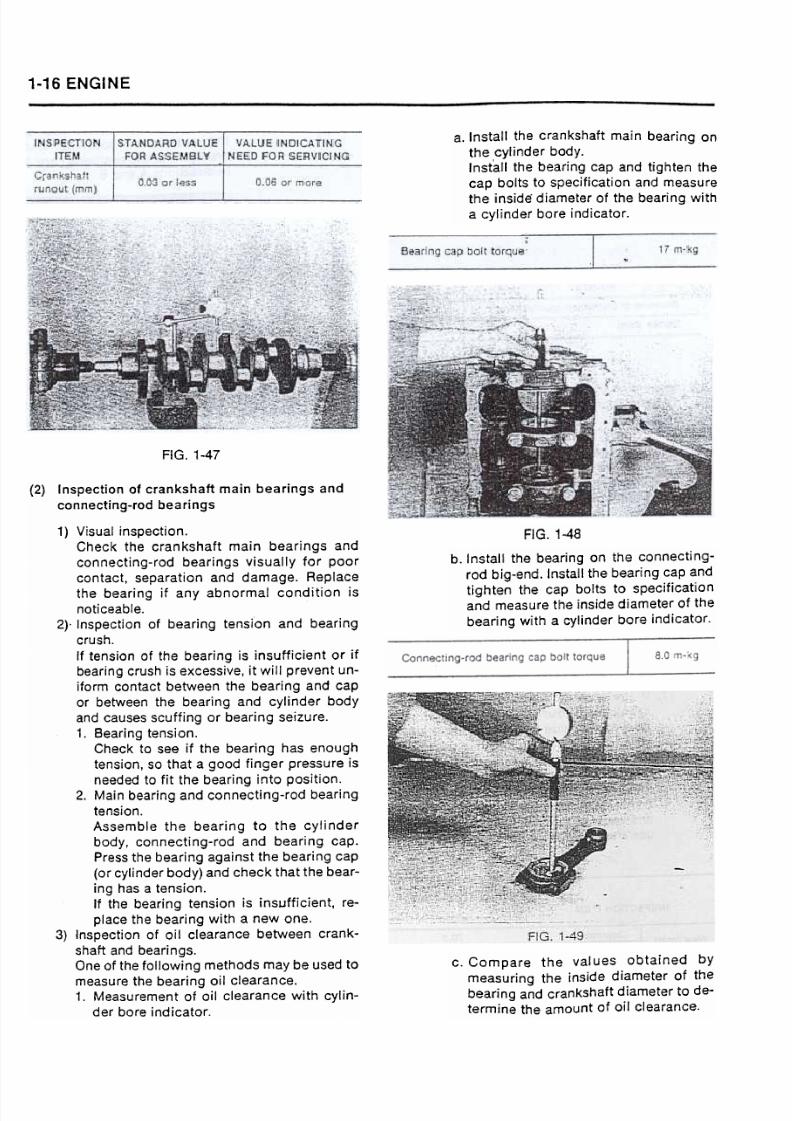
Cylinder head assembly3) Inspection of flywheel
1) Inspection of flywheel for wear.
Measure the depth (t) from the clutch cover
fitting face to the friction face. If the meas-
ured value is beyond the limit. rep(ace the
flywheel. )
3-4
INSPECTION
ITEMENGINE
MOOEL
LlMIT FOR USE
624Q Depth (t)
STANDARD
V ALUE FOR
ASSEMBLY
17.9-18.1 19.0 or more
'23
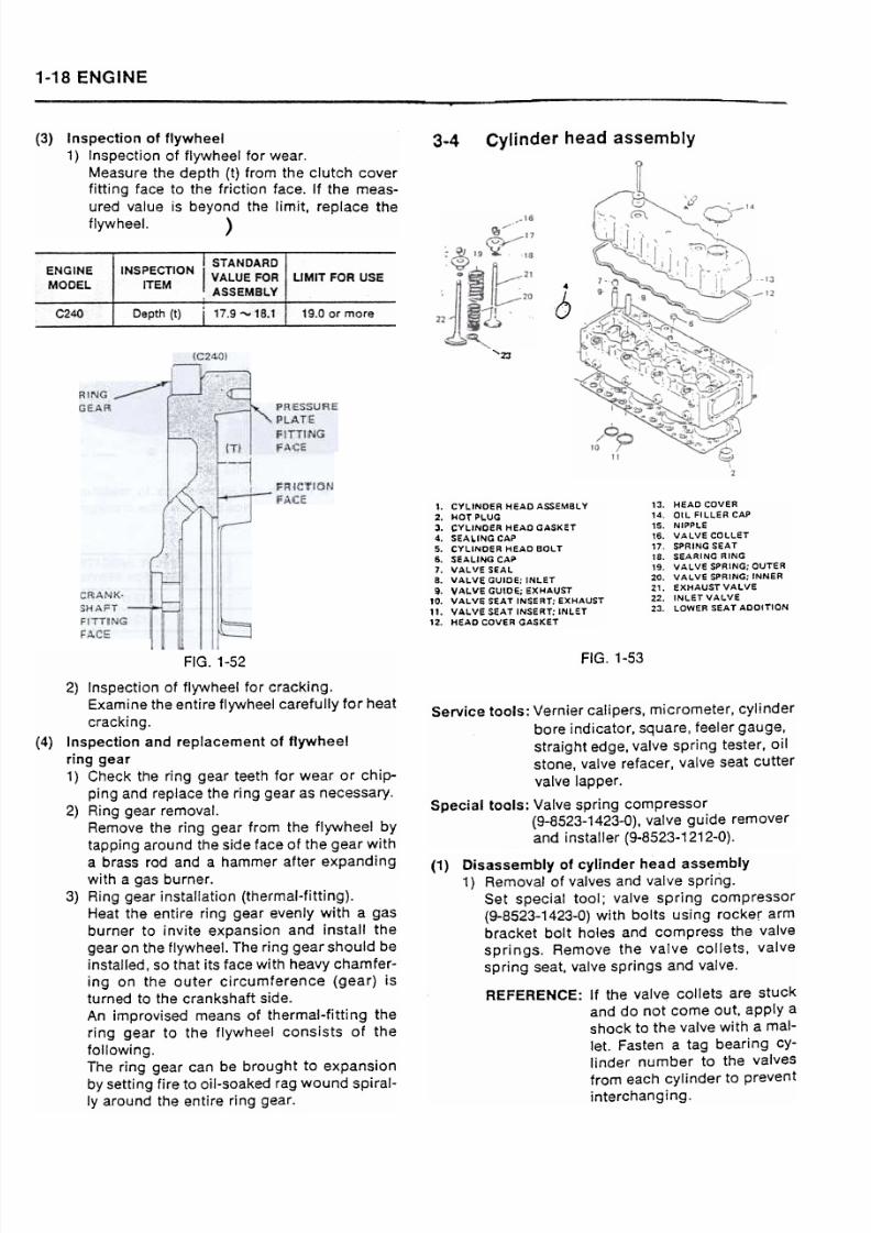
13. HEAO COVER14. OIL FILLER CAP
15. NIPPLE16. VALVE COLLET17. SPRING SEAT1S. SEARING RING19. VALVE SPRING; OUTER20. VALVE SPRING; INNER
21. EXHAUSTVALVE22. INLET VALVE23. LOWER SeAT AOOITION
1. CYLINDER HEAD ASSEMBL Y
2. HOT PLUG3. CYLINOER HEAD GASKET
4. SEALING CAP5. CYLINDE R HEAD BOL T
6. SEALING CAP
7. VALVE SEALB. VAL\lE GUIDE; INLeT
i. VALVE GUIDE; EXHAUST10. VAL\lE SEAT INSERT; EXHAUST
1'. vALve seAT INSERT; lNLeT
12. HeAD COVER aAsKET
FIG. 1-53
Service tools: Vernier caliper5, micrometer, cylinder
bore indicator, 5quare, feeler gauge,
strajght edge, valve spring tester, oil
stone, valve refacer, valve 5eat cutter
valve lapper .
Special tools: Valve 5pring COmpre550r(9-8523-1423-0), valve gujde remover
and jnstaller (9-8523-1212-0).
(1) Disassembly of cylinder head assembly1) Removal of valves and valve spririg.
Set special tool; valve spring compressor(9-8523-1423-0) with bolts using rocker arm
bracket bolt holes and compress the valve
springs. Remove the va(ve collets. valve
spring seat. valve springs and valve.
REFERENCE: If the valv~ collets are stuck
and do not come out. apply a
shock to the valve with a mal-
let. Fasten a tag bearing cY-linder number to the valves
from each cylinder to preventinterchanging.
FIG. 1-52
2) Inspection of flywheel for cracking.
Examine the entire flywheel carefully for heat
cracking.
and replacement of flywheel
ring gear1) Check the ring gear teeth for wear or chip-
ping and replace the ring gear as necessary.
2) Ring gear removal.
Remove the ring gear from the flywheel by
tapping around the side face of the gear with
a brass rod and a hammer after expandingwith a gas burner.
3) Ring gear installation (thermal-fitting).
Heat the entire ring gear evenly with a gas
burner to invite expansion and install the
gear on the flywheel. The ring gear should be
installed, so that its face with heavy chamfer-
ing on the outer cjrcumference (gear) is
turned to the crankshaft side.
An improvised means of thermal-fitting the
ring gear to the flywheel consists of the
following.The ring gear can be brought to expansion
by setting fire to oil-soaked rag wound spiral-
Iy around the entire ring gear.

7/27/2019 SEZIONE 1 PAG. 11-24.pdf
http://slidepdf.com/reader/full/sezione-1-pag-11-24pdf 9/14
ENGINE 1-19
~
If the amount of distortion is in excess of 0.2
mm, Correct with a surface grinder. Replace
the cylinder head assembly if the amount of
distortion is_beyond 0.4 mm.
NOTE: If the cylinder head has been ground.Correct the valve seat inserts. So that
the amount of valve seat depression
is adjusted to 0.7 mm. :
; (Refer to paragraph {5) "Inspection
of valve sea,t inserts'.).
FIG. 1-54
3) In5pection of manifold fitting face of cylinder
head for di5tortion.
Check the intake and eXhau5t manifold fit-
ting face of the cylinder head for di5tortion
u5ing a 5traight edge and a feeler gauge and
correct with a 5urface grinder a5 nece5sary.
(2) In5pection 01 correction 01 cylinder head5
1) Inspectjon of cylinder heads for cracking and
damage.Remove any carbon from the lower face of
the cylinder heads carefully to prevent
scratching of the valve seat faces. Examine
the entire cylinder heads for cracking and
damage using a dye penetrant flaw detector
as needed.
2) Inspection of cylinder head lower face for
distortion.
Hold a straight edge against the lower face of
the cylinder head and check the clearance
between the straight edge and cylinder head
lower face with a feeler gauge.
NOTE: 1. Take measurement in 6
directions.
2. Use a straight edge which is long
enough to cover the entire length
of the cylinder heads in ali direc-
tion of measurement.
4) Hydraulic test.
Cfean the water passages and water jets with
compressed air and check them for restric~
tions. Perform a hydraulic test on the cyljn~
der head for 5 minutes using pressurized
water of 3 kg/cm2.
(3) Inspection and correction of combustion
chambers
1) Inspectjon of hot plugs for depression.
1. Clean the lower face of the cylinder head
with care not to scratch the hot plugs.
2. Position a straight edge across the hot
plugs and check the amount of depres-
sion of the hot plugs using a feeler gauge.
If the measured value js beyond the
specified range, replace the hot plug.
FIG. 1-55

7/27/2019 SEZIONE 1 PAG. 11-24.pdf
http://slidepdf.com/reader/full/sezione-1-pag-11-24pdf 10/14
1-20 ENGINE
4) Installation of hot pJugs.
Install the hot plugs in position by aligning
the ball with the locating groove in the cylin-
der head usjng a mallet or a copper hammer.
NOTE: Hot plugs have been machined after
installatjon on the cylinder head.Make certain the hot plugs are in-
stall~d on their originaJ positions..,
FIG. 1-57
2) Removal of hot plugs and heat shields.1. Insert a bar (3-5 mm in diameter) into the
.injection nozzle hole in the cyHnder head
and tap out the hot plug downward using
a hammer.NOTE: Apply cyl~nder number mark to
the hot plugs with a marking pen
to prevent interchanging.
5) Replacement of hot plugs.1. Wt'en installing a new hot plug. proceed
as f0110WS: nstall the hot plug by aligningthe ball with the 10cating groove on thecylinder head. then drive it in with a mallet
just enough, So that it is settled in position
of jnstallation..6
Fitting interference between hot plug
and cylinder head (mm)0.001 -0.051
14.4 2. Position a piece of protective metal with a
smooth surface over the hot plug and
press it further in by applying a load of
4500-5500 kg with a bench press.
NOTE: Avoid using excess load.IG. 1-58
2. When the hot plug is removed, remove the
heat shield upward by tapping on the
lower face of the heat shield..3) Inspection of combustion chambers.
Remove carbon from the combustion cham-
bers using care not to scratch the hot plug
fitting face of the cylinder head, then check
the inner face of the combustion chambers.
glow plug holes. hot plug fitting face and hot
plugs for damage. Replace the cylinder head
if found to be cracked or damaged. When
checking the combustion chambers, pay par-
ticular attention to the hot plug fitting face as
burrs or high spots on this face will prevent a
positive contact between the hot plug and
cylinder head causing depression or jumpingof hot plug. FIG. 1-60

7/27/2019 SEZIONE 1 PAG. 11-24.pdf
http://slidepdf.com/reader/full/sezione-1-pag-11-24pdf 11/14
ENGINE 1-21
Inlet valve
diameter
'side8.00 7.88
Exhaust valve outside
diameter
8.00 7.85
3. When the hot plug is installed, finish the
face of the hot plug with a surface grinder
to gain matching with a cylinder head.
4. Test for depression or projection by tap-
ping lightly with .a mallet.
6) Installation of heai shield.
Install the heat shield with the flanged side
up on the cylinder head by tapping on the
flange lightly with a brass bar.
NOTE: Discard used heat shield and insta(1 a
new one at reassembly.
2. Inspec~ion of valve head and thickness.
Check ~he seating face of the valve head
for scoring or step we.ar-and correct with a
ya:Jve refacer as necessary.
Measure the thickness of the valve head.
Replace the valve if mèasured valve is less
than 1.0 mm.
FIG -63
2 Inspection and replacement of valve guides.
1. Inspection of valve guide inner wall for
wear.
Insert the valve stem into the valve guide
and check for looseness to estimate the
amount of wear in the valve guide inner
wall.
If the amount of clearance between the
valve stem and valve guide is beyond thevalue indicating need for servicing. re-
pIace the valve guide together with the
valve.
(4) Inspection and correction of valves and valve
guides1) Inspection of valves.
1. Inspection of valve stem for wear .
With an outside micrometer measure the
diameter of the valve stem at the upper,
center and lower portions. If the mea-
sured values are beyond the limit. replace
the vafve together with the valve guide.
Slight steps on the valve stem end may be
removed with an oil stone orvalve refacer.

7/27/2019 SEZIONE 1 PAG. 11-24.pdf
http://slidepdf.com/reader/full/sezione-1-pag-11-24pdf 12/14
1-22 ENGINE
3) Removal of vaJve guides.
To remove the intake or exhaust valve guide.
proceed as follows: Position the cylinder
head with the lower f~ce up and drive out the
valve guide using speciaf tool; remover and
installer (9-8523-1212-0) and a hammer.
\
\
\
.//
,-
FIG. 1-67
5) Jnstallaticn cf valve guide cil seals"
Drive the cil seal intc the intake valve guide;'c",:;"; .:@,fiti:" ..::-.::'i:.."-;:'~\~~:;V~11!~IG. 1-65
~,~!?
.'..G~i
';~~~~1;
'.\.;'.~y~
:~~:~;,~'i'~~f
~~~~
4) Installation of vafve guides.
To install the valve guide, proceed as fol-
I 19W5: Position the cylinder head with the
lower face down on a suitable support and
set the adapter to the special tool; remover
and installer (9-8523-1212-0), then install the
valve guide using a hammer.
NOTE: Apply engine oil to the outer circum-
ference of the valve guide before
installation.
FIG. 1-68
(5) Inspectjon and rep'acement of va've seat
insertsExcessive wear in the valve seat insert will pre-
vent normal contact between the valve and seat
resulting poor engine performance. Check the
width of contact and amount of depression of
the valve seat inserts. If the measured values are
beyond the value indicating need for servicing.
replace the valve seat inserts with new ones.1) 'nspectjon of valve seat i.nserts for wear .
Since it is impracticable to check the amount
of wear in the valve seat inserts as fitted in
position of installation. install a new valve
into the valve seat insert and check the
amount of depression of the valve head from
the cylinder head lower face to estimate the
amount of wear in the valve seat insert.
Replace the valve seat insert if the measured
value js beyond the value indicating need for
servicing.IG. 1-66

7/27/2019 SEZIONE 1 PAG. 11-24.pdf
http://slidepdf.com/reader/full/sezione-1-pag-11-24pdf 13/14
ENGINE 1-23
FIG. 1-69
2) Inspectian af valve seat cantact width.
If the valve seat cantact width is beyand thevalue indicating need far servicing. carrect
with a valve seat cutter.
VALUE INDICATING
NE ED FOR
SERVICING
INSPECTION
ITEM
STANDARD VALVE
FOR ASSEMBL y
3) Replacement of valve seat inserts.
1. Removal.
With an electric welder, give welding
beads to opposed two (2) portions of the
inner face of the vaJve seat insert. Then
alJow the cylinder head to cool off from 3
to 5 minutes, so that contraction of the
valve seat insert takes pIace, permitting
removal with a screwdriver.
.2. Inspection of fitting interference between
valve seat insert and cylinder head.
..Clean the valve seat insert bore to remove
.-carbon and oxidized deposits. Measure
the inside diameter of the valve seat insert
bore and outside diameter of a new valve
seat insert to be installed and compare
the measured values to determine the
amount of fitting interference. If the
amount of fitting interference is less than
0.06 mm, correct the valve seat insert bore
by means of welding excess metal and
machining.3. Installation.
Press a new valve seat insert into the bore
using a bench press. When the valve seat
insert is installed, check the amount of
depression of the valve from the lower
face of the cylinder head. If the amount of
depression of the valve is less than 0.7
mm, correct with a valve seat cutter.
4. Inspection and correction of valve seats.
Apply thin coat of Special compound (red
lead and oil mixture) to the seating face of
the valve evenly and bring the valve into
light contact with the seat to get an im-
pression of valve seat contact. Check and
see if the contact width is within the stan-
dard value for assembly given under
paragraph 2) "Inspection of valve seat
contact width" and is wef( centered on the
valve seat.
FIG. 1-70
/
1500
-~--.;~~-=~=:: ~
:r::=:::t---
~~
'l-'
FIG -72IG. 1-71

7/27/2019 SEZIONE 1 PAG. 11-24.pdf
http://slidepdf.com/reader/full/sezione-1-pag-11-24pdf 14/14
1-24 ENGINE
If the impression of contact or contact
width is abnormal. correct with a valve
seat cutter and Ia.p the valve seat using
fine lapping compound and valve lapper.
(6) Inspection of valve springs
1) Check the valve springs visually fo_r damage.
!,.~~~~~;~~~
,,~~;;:;#~,,~
1_ut
't\o..',',,'
;:;"'~"
if~i~~~
~~
~~.
._~""..,!i-irl~
~:;ii::1j;;~'fi~~.,.-' "",::;;;,:~~~1i
il~ii
I~~
.!:::~:~
FIG -73
2) Check spring tension and free length of the
valve springs with a valve spring tester and
replace if measured value is beyond the limit.
3) Inspection of valve springs for inclination.
Hold the valve spring on a surface plate in
upright position and measure the amount of
inclination of the valve spring. If the amountof incfination is beyond the fimit, replace the
valve spring.FIG
STANDARD VALUE
FaR ASSEMBL y
NOMINAL
DtMENSIONLlMIT FOR USEINSPECTION ITEM
When compressed
to fitting length of
39mm
Outer
spring
15.718.5 17.5 19.5
Spring
tension (kg) When compressed
to fitting length of
37mm
Inner
spring7.05.8 8.8.3
Outer
spring
44.56.0
Free length (mm)
Inner
spring
41.542.9
Outer and
inner spring1.0
Incfination from vertical (mm)
3) In~tall the valve springs and valve spring seat
and set special tool: valve spring compressor(9-8523-1423-0) to the rocker arm bracket
bolt holes. then compress the valve spring
and install the valve collets.
(7) Reassembly of cylinder head assembly
1) Apply clean engine ojl to the valve stem be-
fore jnstalling the valve into the valve guide.
2) Position a suitable support under the cylin-
der head to prevent lowering of the valves.