Embed Size (px)
Citation preview
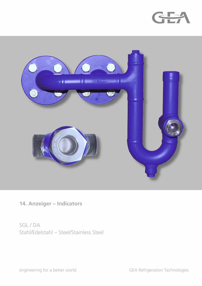
14. Anzeiger – Indicators
SGL / DA
Stahl/Edelstahl – Steel/Stainless Steel
engineering for a better world GEA Refrigeration Technologies
GEA Refrigeration Technologies
GEA AWP GmbH 14.1
Armaturenstraße 2, 17291 Prenzlau, Germany Tel: +49 39848559-0 Fax: +49 39848559-18 [email protected], www.awpvalves.com 2013-1
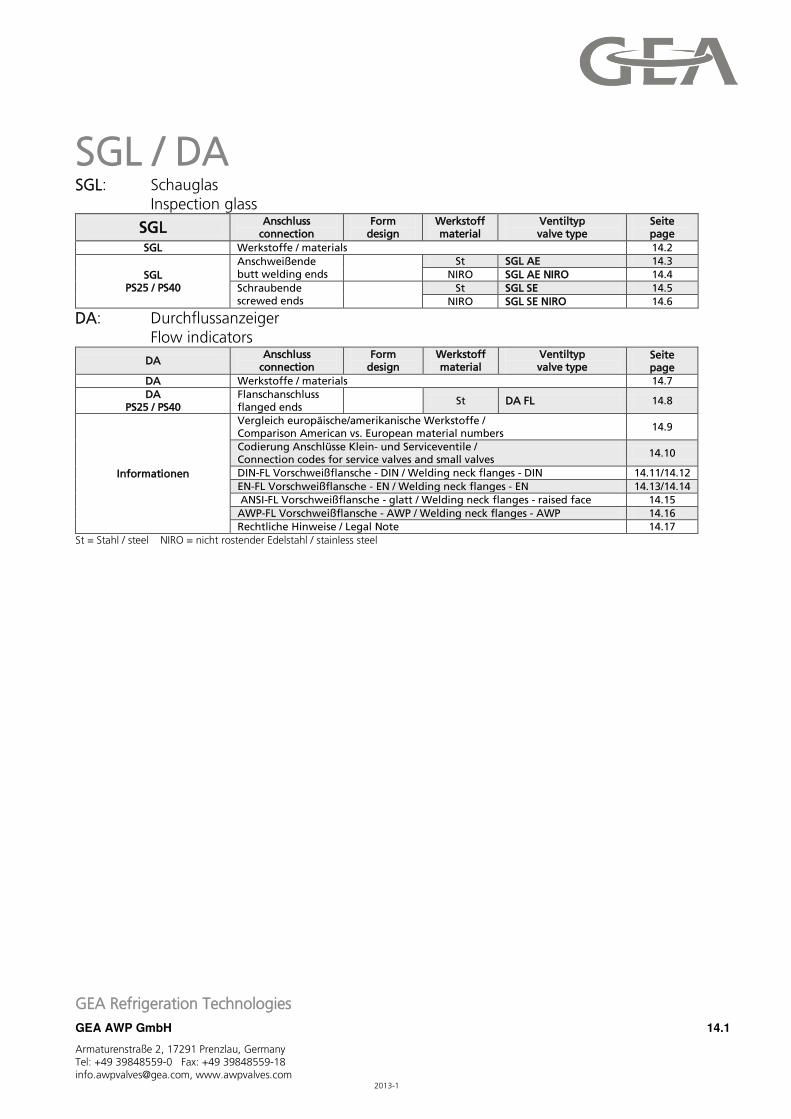
SGL / DA SGL: Schauglas Inspection glass
SGL Anschluss
connection Form
design Werkstoff material
Ventiltyp valve type
Seite page
SGL Werkstoffe / materials 14.2
SGL PS25 / PS40
Anschweißende butt welding ends
St SGL AE 14.3
NIRO SGL AE NIRO 14.4
Schraubende screwed ends
St SGL SE 14.5
NIRO SGL SE NIRO 14.6
DA: Durchflussanzeiger Flow indicators
DA Anschluss
connection Form
design Werkstoff material
Ventiltyp valve type
Seite page
DA Werkstoffe / materials 14.7
DA PS25 / PS40
Flanschanschluss flanged ends
St DA FL 14.8
Informationen
Vergleich europäische/amerikanische Werkstoffe / Comparison American vs. European material numbers
14.9
Codierung Anschlüsse Klein- und Serviceventile / Connection codes for service valves and small valves
14.10
DIN-FL Vorschweißflansche - DIN / Welding neck flanges - DIN 14.11/14.12
EN-FL Vorschweißflansche - EN / Welding neck flanges - EN 14.13/14.14
ANSI-FL Vorschweißflansche - glatt / Welding neck flanges - raised face 14.15
AWP-FL Vorschweißflansche - AWP / Welding neck flanges - AWP 14.16
Rechtliche Hinweise / Legal Note 14.17
St = Stahl / steel NIRO = nicht rostender Edelstahl / stainless steel
GEA Refrigeration Technologies
GEA AWP GmbH 14.2
Armaturenstraße 2, 17291 Prenzlau, Germany Tel: +49 39848559-0 Fax: +49 39848559-18 [email protected], www.awpvalves.com 2013-1
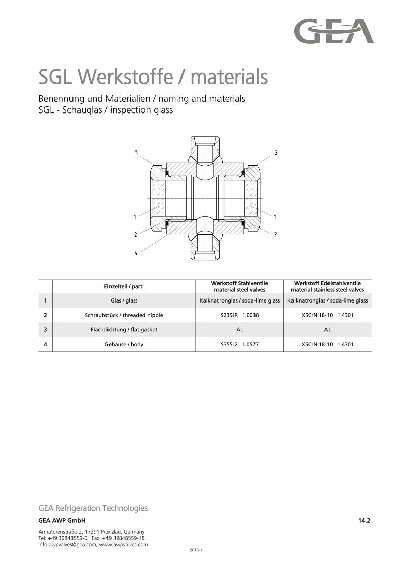
SGL Werkstoffe / materials Benennung und Materialien / naming and materials SGL - Schauglas / inspection glass
Einzelteil / part: Werkstoff Stahlventile material steel valves
Werkstoff Edelstahlventile material stainless steel valves
1 Glas / glass Kalknatronglas / soda-lime glass Kalknatronglas / soda-lime glass
2 Schraubstück / threaded nipple S235JR 1.0038 X5CrNi18-10 1.4301
3 Flachdichtung / flat gasket AL AL
4 Gehäuse / body S355J2 1.0577 X5CrNi18-10 1.4301
GEA Refrigeration Technologies
GEA AWP GmbH 14.3
Armaturenstraße 2, 17291 Prenzlau, Germany Tel: +49 39848559-0 Fax: +49 39848559-18 [email protected], www.awpvalves.com 2013-1
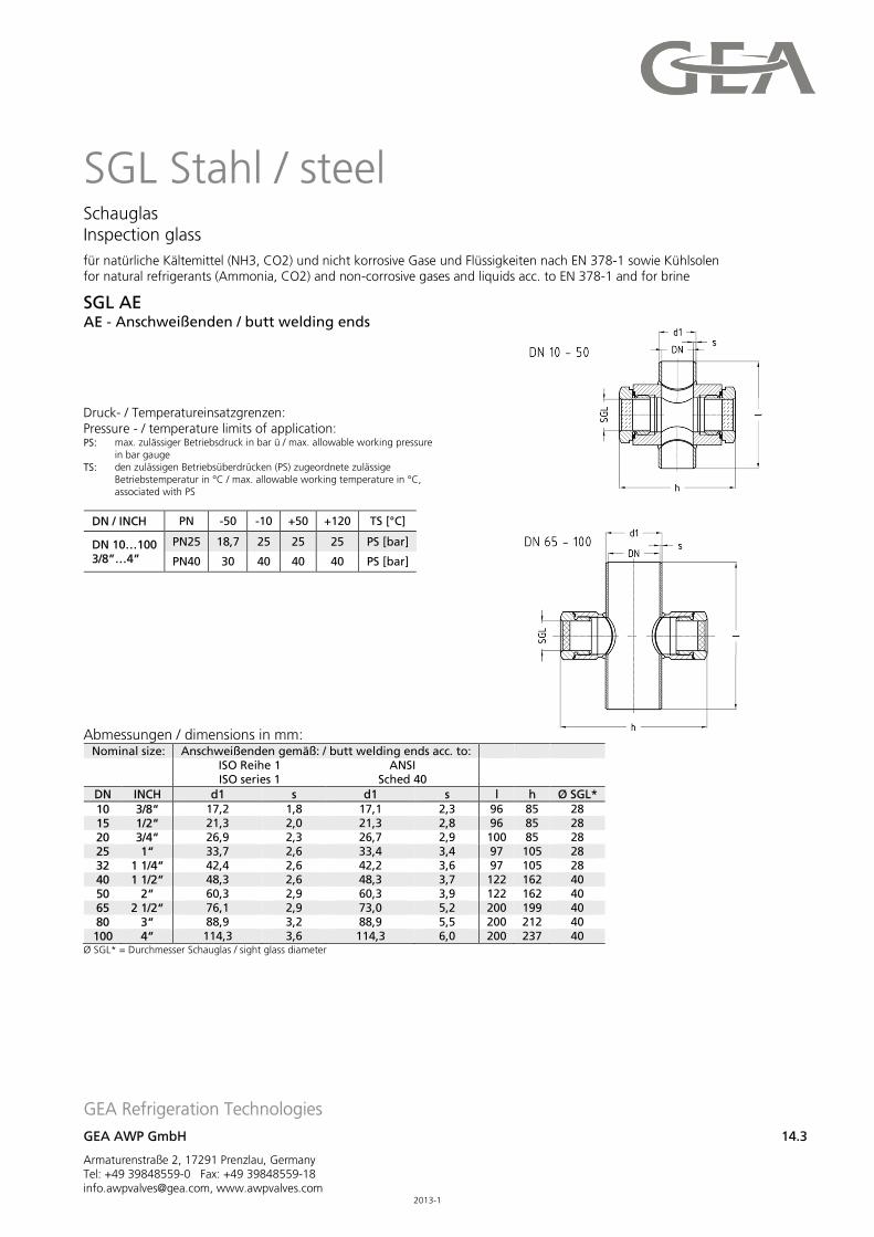
SGL Stahl / steel Schauglas Inspection glass
für natürliche Kältemittel (NH3, CO2) und nicht korrosive Gase und Flüssigkeiten nach EN 378-1 sowie Kühlsolen for natural refrigerants (Ammonia, CO2) and non-corrosive gases and liquids acc. to EN 378-1 and for brine
SGL AE AE - Anschweißenden / butt welding ends
Druck- / Temperatureinsatzgrenzen: Pressure - / temperature limits of application: PS: max. zulässiger Betriebsdruck in bar ü / max. allowable working pressure
in bar gauge
TS: den zulässigen Betriebsüberdrücken (PS) zugeordnete zulässige Betriebstemperatur in °C / max. allowable working temperature in °C, associated with PS
DN / INCH PN -50 -10 +50 +120 TS [°C]
DN 10…100 3/8”…4”
PN25 18,7 25 25 25 PS [bar]
PN40 30 40 40 40 PS [bar]
Abmessungen / dimensions in mm:
Nominal size: Anschweißenden gemäß: / butt welding ends acc. to:
ISO Reihe 1 ISO series 1
ANSI Sched 40
DN INCH d1 s d1 s l h Ø SGL*
10 3/8“ 17,2 1,8 17,1 2,3 96 85 28 15 1/2“ 21,3 2,0 21,3 2,8 96 85 28 20 3/4“ 26,9 2,3 26,7 2,9 100 85 28 25 1“ 33,7 2,6 33,4 3,4 97 105 28 32 1 1/4“ 42,4 2,6 42,2 3,6 97 105 28 40 1 1/2“ 48,3 2,6 48,3 3,7 122 162 40 50 2“ 60,3 2,9 60,3 3,9 122 162 40 65 2 1/2“ 76,1 2,9 73,0 5,2 200 199 40 80 3“ 88,9 3,2 88,9 5,5 200 212 40 100 4“ 114,3 3,6 114,3 6,0 200 237 40
Ø SGL* = Durchmesser Schauglas / sight glass diameter

GEA Refrigeration Technologies
GEA AWP GmbH 14.4
Armaturenstraße 2, 17291 Prenzlau, Germany Tel: +49 39848559-0 Fax: +49 39848559-18 [email protected], www.awpvalves.com 2013-1
SGL Edelstahl / stainless steel Schauglas Inspection glass
für natürliche Kältemittel (NH3, CO2) und nicht korrosive Gase und Flüssigkeiten nach EN 378-1 sowie Kühlsolen for natural refrigerants (Ammonia, CO2) and non-corrosive gases and liquids acc. to EN 378-1 and for brine
SGL AE NIRO AE - Anschweißenden / butt welding ends
Druck- / Temperatureinsatzgrenzen: Pressure - / temperature limits of application: PS: max. zulässiger Betriebsdruck in bar ü / max. allowable working pressure
in bar gauge
TS: den zulässigen Betriebsüberdrücken (PS) zugeordnete zulässige Betriebstemperatur in °C / max. allowable working temperature in °C, associated with PS
DN / INCH PN -50 -10 +50 +120 TS [°C]
DN 10…100 3/8”…4”
PN25 25 25 25 25 PS [bar]
PN40 40 40 40 40 PS [bar]
Abmessungen / dimensions in mm:
Nominal size: Anschweißenden gemäß: / butt welding ends acc. to:
ISO Reihe 1 ISO series 1
ANSI Sched 40
DN INCH d1 s d1 s l h Ø SGL*
10 3/8“ 17,2 1,8 17,1 2,3 96 85 28 15 1/2“ 21,3 2,0 21,3 2,8 96 85 28 20 3/4“ 26,9 2,3 26,7 2,9 100 85 28 25 1“ 33,7 2,6 33,4 3,4 97 105 28 32 1 1/4“ 42,4 2,6 42,2 3,6 97 105 28 40 1 1/2“ 48,3 2,6 48,3 3,7 122 162 40 50 2“ 60,3 2,9 60,3 3,9 122 162 40 65 2 1/2“ 76,1 2,9 73,0 5,2 200 199 40 80 3“ 88,9 3,2 88,9 5,5 200 212 40 100 4“ 114,3 3,6 114,3 6,0 200 237 40
Ø SGL* = Durchmesser Schauglas / sight glass diameter
GEA Refrigeration Technologies
GEA AWP GmbH 14.5
Armaturenstraße 2, 17291 Prenzlau, Germany Tel: +49 39848559-0 Fax: +49 39848559-18 [email protected], www.awpvalves.com 2013-1
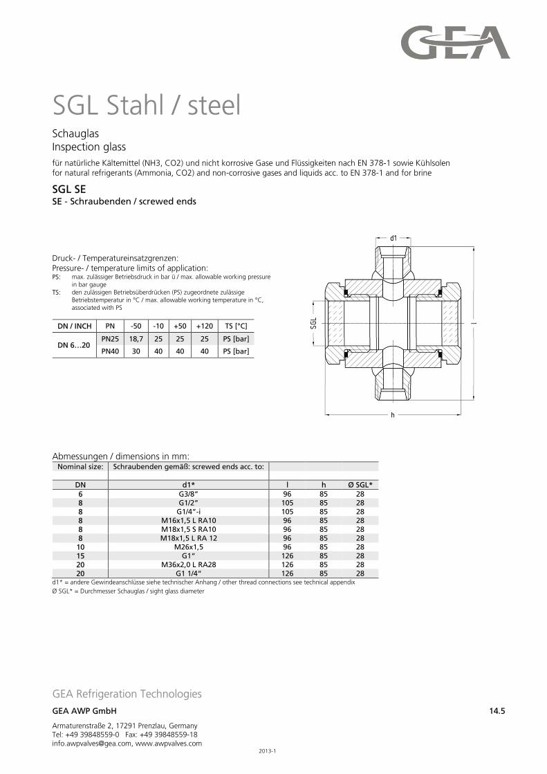
SGL Stahl / steel Schauglas Inspection glass
für natürliche Kältemittel (NH3, CO2) und nicht korrosive Gase und Flüssigkeiten nach EN 378-1 sowie Kühlsolen for natural refrigerants (Ammonia, CO2) and non-corrosive gases and liquids acc. to EN 378-1 and for brine
SGL SE SE - Schraubenden / screwed ends
Druck- / Temperatureinsatzgrenzen: Pressure- / temperature limits of application: PS: max. zulässiger Betriebsdruck in bar ü / max. allowable working pressure
in bar gauge
TS: den zulässigen Betriebsüberdrücken (PS) zugeordnete zulässige Betriebstemperatur in °C / max. allowable working temperature in °C, associated with PS
DN / INCH PN -50 -10 +50 +120 TS [°C]
DN 6…20 PN25 18,7 25 25 25 PS [bar]
PN40 30 40 40 40 PS [bar]
Abmessungen / dimensions in mm:
Nominal size: Schraubenden gemäß: screwed ends acc. to:
DN d1* l h Ø SGL*
6 G3/8” 96 85 28 8 G1/2” 105 85 28 8 G1/4”-i 105 85 28 8 M16x1,5 L RA10 96 85 28 8 M18x1,5 S RA10 96 85 28 8 M18x1,5 L RA 12 96 85 28
10 M26x1,5 96 85 28 15 G1“ 126 85 28 20 M36x2,0 L RA28 126 85 28 20 G1 1/4“ 126 85 28
d1* = andere Gewindeanschlüsse siehe technischer Anhang / other thread connections see technical appendix
Ø SGL* = Durchmesser Schauglas / sight glass diameter
GEA Refrigeration Technologies
GEA AWP GmbH 14.6
Armaturenstraße 2, 17291 Prenzlau, Germany Tel: +49 39848559-0 Fax: +49 39848559-18 [email protected], www.awpvalves.com 2013-1
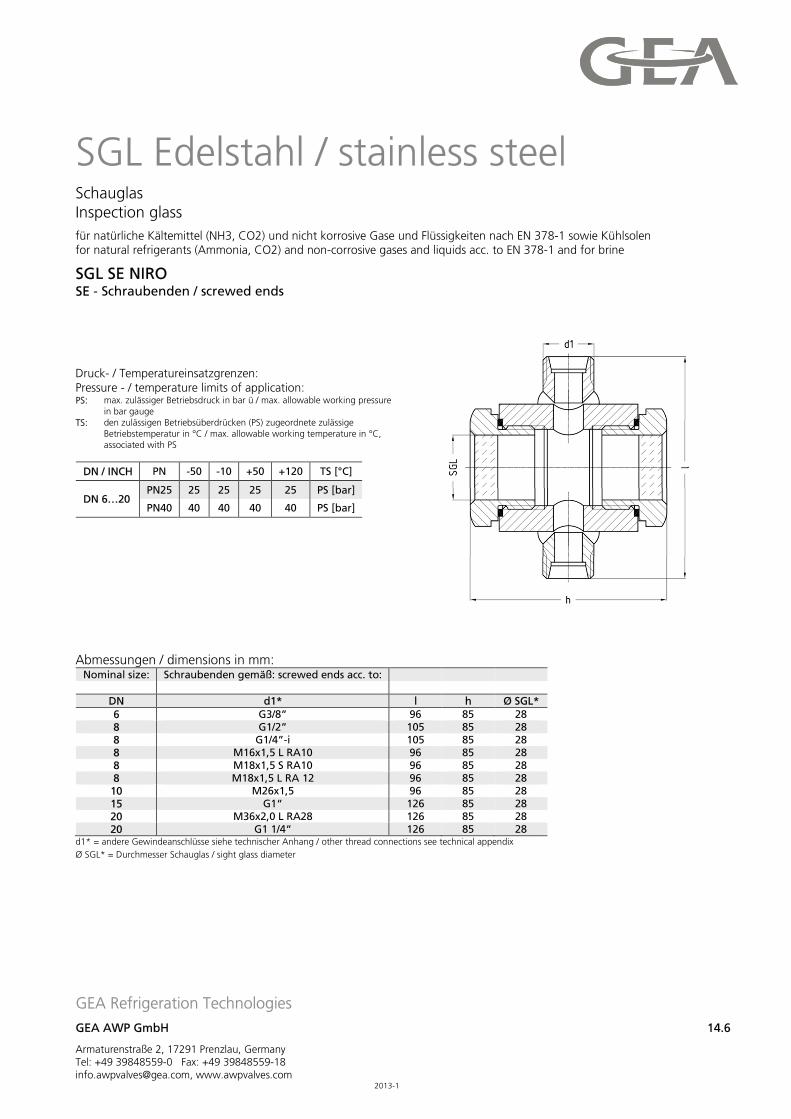
SGL Edelstahl / stainless steel Schauglas Inspection glass
für natürliche Kältemittel (NH3, CO2) und nicht korrosive Gase und Flüssigkeiten nach EN 378-1 sowie Kühlsolen for natural refrigerants (Ammonia, CO2) and non-corrosive gases and liquids acc. to EN 378-1 and for brine
SGL SE NIRO SE - Schraubenden / screwed ends
Druck- / Temperatureinsatzgrenzen: Pressure - / temperature limits of application: PS: max. zulässiger Betriebsdruck in bar ü / max. allowable working pressure
in bar gauge
TS: den zulässigen Betriebsüberdrücken (PS) zugeordnete zulässige Betriebstemperatur in °C / max. allowable working temperature in °C, associated with PS
DN / INCH PN -50 -10 +50 +120 TS [°C]
DN 6…20 PN25 25 25 25 25 PS [bar]
PN40 40 40 40 40 PS [bar]
Abmessungen / dimensions in mm:
Nominal size: Schraubenden gemäß: screwed ends acc. to:
DN d1* l h Ø SGL*
6 G3/8” 96 85 28 8 G1/2” 105 85 28 8 G1/4”-i 105 85 28 8 M16x1,5 L RA10 96 85 28 8 M18x1,5 S RA10 96 85 28 8 M18x1,5 L RA 12 96 85 28
10 M26x1,5 96 85 28 15 G1“ 126 85 28 20 M36x2,0 L RA28 126 85 28 20 G1 1/4“ 126 85 28
d1* = andere Gewindeanschlüsse siehe technischer Anhang / other thread connections see technical appendix
Ø SGL* = Durchmesser Schauglas / sight glass diameter
GEA Refrigeration Technologies
GEA AWP GmbH 14.7
Armaturenstraße 2, 17291 Prenzlau, Germany Tel: +49 39848559-0 Fax: +49 39848559-18 [email protected], www.awpvalves.com 2013-1
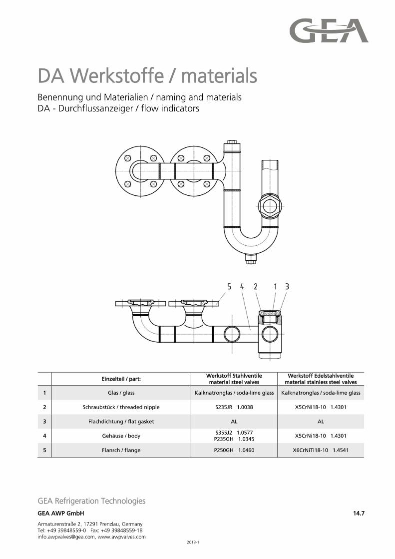
DA Werkstoffe / materials Benennung und Materialien / naming and materials DA - Durchflussanzeiger / flow indicators
Einzelteil / part: Werkstoff Stahlventile material steel valves
Werkstoff Edelstahlventile material stainless steel valves
1 Glas / glass Kalknatronglas / soda-lime glass Kalknatronglas / soda-lime glass
2 Schraubstück / threaded nipple S235JR 1.0038 X5CrNi18-10 1.4301
3 Flachdichtung / flat gasket AL AL
4 Gehäuse / body S355J2 1.0577
P235GH 1.0345 X5CrNi18-10 1.4301
5 Flansch / flange P250GH 1.0460 X6CrNiTi18-10 1.4541
GEA Refrigeration Technologies
GEA AWP GmbH 14.8
Armaturenstraße 2, 17291 Prenzlau, Germany Tel: +49 39848559-0 Fax: +49 39848559-18 [email protected], www.awpvalves.com 2015-3
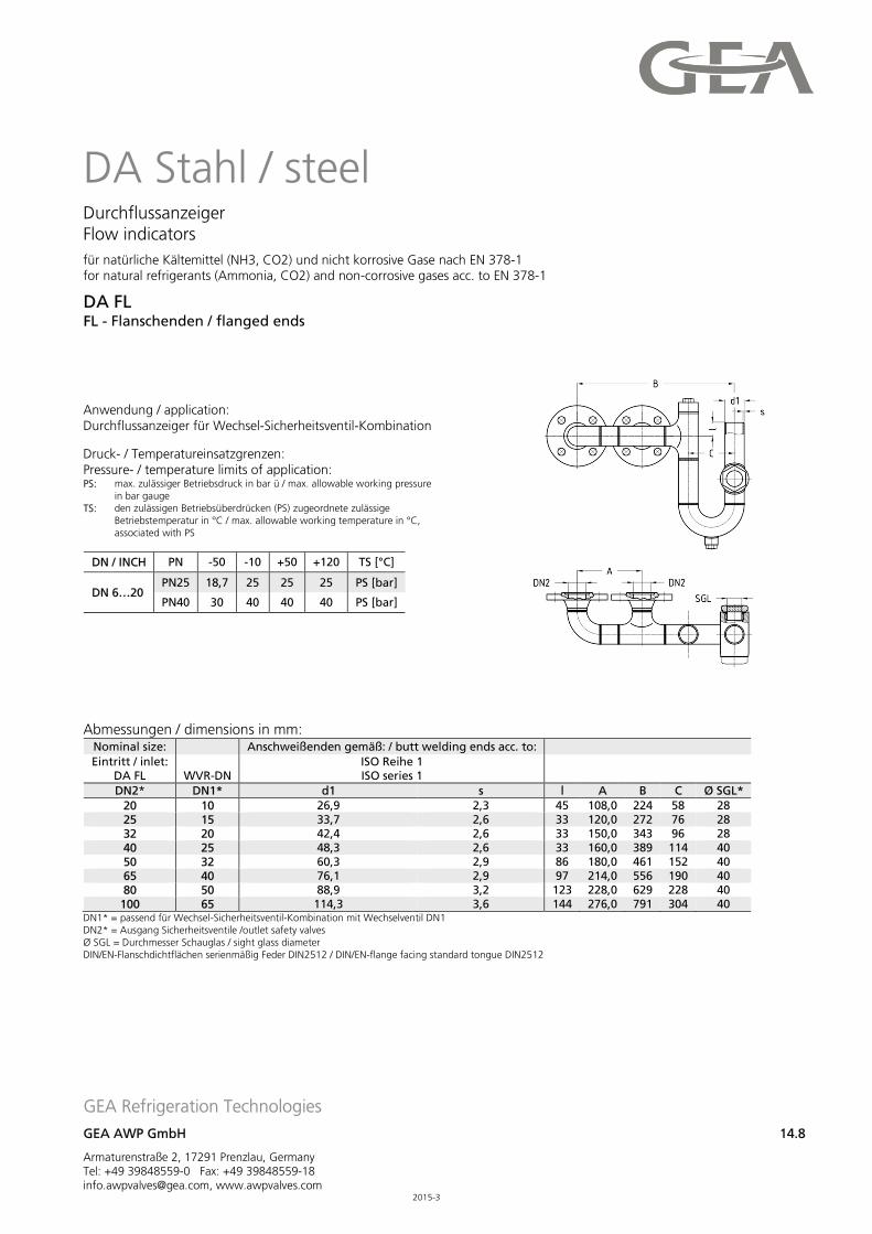
DA Stahl / steel Durchflussanzeiger Flow indicators
für natürliche Kältemittel (NH3, CO2) und nicht korrosive Gase nach EN 378-1 for natural refrigerants (Ammonia, CO2) and non-corrosive gases acc. to EN 378-1
DA FL FL - Flanschenden / flanged ends
Anwendung / application: Durchflussanzeiger für Wechsel-Sicherheitsventil-Kombination
Druck- / Temperatureinsatzgrenzen: Pressure- / temperature limits of application: PS: max. zulässiger Betriebsdruck in bar ü / max. allowable working pressure
in bar gauge
TS: den zulässigen Betriebsüberdrücken (PS) zugeordnete zulässige Betriebstemperatur in °C / max. allowable working temperature in °C, associated with PS
DN / INCH PN -50 -10 +50 +120 TS [°C]
DN 6…20 PN25 18,7 25 25 25 PS [bar]
PN40 30 40 40 40 PS [bar]
Abmessungen / dimensions in mm:
Nominal size: Anschweißenden gemäß: / butt welding ends acc. to:
Eintritt / inlet: DA FL WVR-DN
ISO Reihe 1 ISO series 1
DN2* DN1* d1 s l A B C Ø SGL*
20 10 26,9 2,3 45 108,0 224 58 28 25 15 33,7 2,6 33 120,0 272 76 28 32 20 42,4 2,6 33 150,0 343 96 28 40 25 48,3 2,6 33 160,0 389 114 40 50 32 60,3 2,9 86 180,0 461 152 40 65 40 76,1 2,9 97 214,0 556 190 40 80 50 88,9 3,2 123 228,0 629 228 40
100 65 114,3 3,6 144 276,0 791 304 40 DN1* = passend für Wechsel-Sicherheitsventil-Kombination mit Wechselventil DN1 DN2* = Ausgang Sicherheitsventile /outlet safety valves Ø SGL = Durchmesser Schauglas / sight glass diameter DIN/EN-Flanschdichtflächen serienmäßig Feder DIN2512 / DIN/EN-flange facing standard tongue DIN2512
GEA Refrigeration Technologies
GEA AWP GmbH 14.09
Armaturenstraße 2, 17291 Prenzlau, Germany Tel: +49 39848559-0 Fax: +49 39848559-18 [email protected], www.awpvalves.com 2013-1
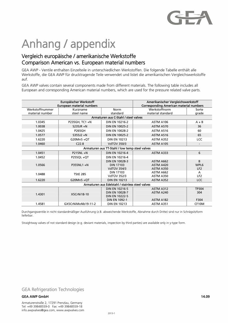
Anhang / appendix Vergleich europäische / amerikanische Werkstoffe Comparison American vs. European material numbers GEA AWP - Ventile enthalten Einzelteile in unterschiedlichen Werkstoffen. Die folgende Tabelle enthält alle Werkstoffe, die GEA AWP für drucktragende Teile verwendet und listet die amerikanischen Vergleichswerkstoffe auf.
GEA AWP valves contain several components made from different materials. The following table includes all European and corresponding American material numbers, which are used for the pressure related valve parts.
Europäischer Werkstoff European material numbers
Amerikanischer Vergleichswerkstoff Corresponding American material numbers
Werkstoffnummer material number
Kurzname steel name
Norm standard
Werkstoffnorm material standard
Sorte grade
Armaturen aus C-Stahl / steel valves
1.0345 P235GH, TC1 +N DIN EN 10216-2 ASTM A106 A + B
1.0038 S235JR +N DIN EN 10025-2 ASTM A570 36
1.0425 P265GH DIN EN 10028-2 ASTM A516 60
1.0577 S355J2 +N DIN EN 10025-2 ASTM A516 65
1.6220 G20Mn5 +QT DIN EN 10213 ASTM A352 LCC
1.0460 C22.8 VdTÜV 350/3 ASTM A105 -
Armaturen aus TT-Stahl / low temp steel valves
1.0451 P215NL +N DIN EN 10216-4 ASTM A333 6
1.0452 P255QL +QT DIN EN 10216-4
1.0566 P355NL1 +N DIN EN 10028-3
DIN 17103 VdTÜV 354/3
ASTM A662 ASTM A420 ASTM A350
B WPL6 LF2
1.0488 TStE 285 DIN 17103
VdTÜV 352/3 ASTM A662 ASTM A350
A LF2
1.6220 G20Mn5 +QT DIN EN 10213 ASTM A352 LCC
Armaturen aus Edelstahl / stainless steel valves
1.4301 X5CrNi18-10
DIN EN 10216-5 DIN EN 10028-7 DIN EN 10222-5 DIN EN 1092-1
ASTM A312 ASTM A240
ASTM A182
TP304 304
F304
1.4581 GX5CrNiMoNb19-11-2 DIN EN 10213 ASTM A351 CF10M
Durchgangsventile in nicht standardmäßiger Ausführung (z.B. abweichende Werkstoffe, Abnahme durch Dritte) sind nur in Schrägsitzform lieferbar. Straightway valves of not standard design (e.g. deviant materials, inspection by third parties) are available only in y-type form.
GEA Refrigeration Technologies
GEA AWP GmbH 14.10
Armaturenstraße 2, 17291 Prenzlau, Germany Tel: +49 39848559-0 Fax: +49 39848559-18 [email protected], www.awpvalves.com 2013-1
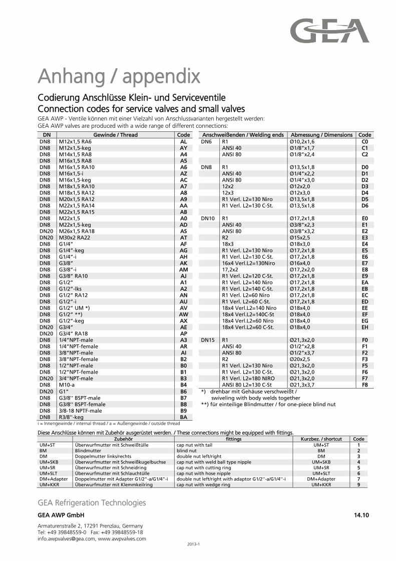
Anhang / appendix Codierung Anschlüsse Klein- und Serviceventile Connection codes for service valves and small valves GEA AWP - Ventile können mit einer Vielzahl von Anschlussvarianten hergestellt werden: GEA AWP valves are produced with a wide range of different connections:
DN Gewinde / Thread Code
Anschweißenden / Welding ends Abmessung / Dimensions Code DN8 M12x1,5 RA6 AL DN6 R1 Ø10,2x1,6 C0 DN8 M12x1,5-keg AY ANSI 40 Ø1/8”x1,7 C1 DN8 M14x1,5 RA8 A4 ANSI 80 Ø1/8”x2,4 C2 DN8 M16x1,5 RA8 A5 DN8 M16x1,5 RA10 A6 DN8 R1 Ø13,5x1,8 D0 DN8 M16x1,5-i AZ ANSI 40 Ø1/4”x2,2 D1 DN8 M16x1,5-keg AC ANSI 80 Ø1/4”x3,0 D2 DN8 M18x1,5 RA10 A7 12x2 Ø12x2,0 D3 DN8 M18x1,5 RA12 A8 12x3 Ø12x3,0 D4 DN8 M20x1,5 RA12 A9 R1 Verl. L2=130 Niro Ø13,5x1,8 D5 DN8 M22x1,5 RA14 AA R1 Verl. L2=130 C-St. Ø13,5x1,8 D6 DN8 M22x1,5 RA15 AB DN8 M22x1,5 A0 DN10 R1 Ø17,2x1,8 E0 DN8 M22x1,5-keg AD ANSI 40 Ø3/8”x2,3 E1 DN20 M26x1,5 RA18 AS ANSI 80 Ø3/8”x3,2 E2 DN20 M30x2 RA22 AT R2 Ø15x2,5 E3 DN8 G1/4” AF 18x3 Ø18x3,0 E4 DN8 G1/4”-keg AG R1 Verl. L2=130 Niro Ø17,2x1,8 E5 DN8 G1/4”-i AH R1 Verl. L2=130 C-St. Ø17,2x1,8 E6 DN8 G3/8” AK 16x4 Verl.L2=130Niro Ø16x4,0 E7 DN8 G3/8”-i AM 17,2x2 Ø17,2x2,0 E8 DN8 G3/8” RA10 AJ R1 Verl. L2=120 C-St. Ø17,2x1,8 E9 DN8 G1/2” A1 R1 Verl. L2=140 Niro Ø17,2x1,8 EA DN8 G1/2”-lks A2 R1 Verl. L2=140 C-St. Ø17,2x1,8 EB DN8 G1/2” RA12 AN R1 Verl. L2=60 Niro Ø17,2x1,8 EC DN8 G1/2”-i AU R1 Verl. L2=60 C-St. Ø17,2x1,8 ED DN8 G1/2” UM *) AV 18x4 Verl.L2=140 Niro Ø18x4,0 EE DN8 G1/2” **) AW 18x4 Verl.L2=140C-St Ø18x4,0 EF DN8 G1/2”-keg AX 18x4 Verl.L2=60 Niro Ø18x4,0 EG DN20 G3/4” AE 18x4 Verl.L2=60 C-St. Ø18x4,0 EH DN20 G3/4” RA18 AP DN8 1/4”NPT-male A3 DN15 R1 Ø21,3x2,0 F0 DN8 1/4”NPT-female AR ANSI 40 Ø1/2”x2,8 F1 DN8 3/8”NPT-male AI ANSI 80 Ø1/2”x3,7 F2 DN8 3/8”NPT-female B2 R2 Ø20x2,5 F3 DN8 1/2”NPT-male B0 R1 Verl. L2=130 Niro Ø21,3x2,0 F5 DN8 1/2”NPT-female B1 R1 Verl. L2=130 C-St. Ø21,3x2,0 F6 DN20 3/4''NPT-male B3 R1 Verl. L2=180 NIRO Ø21,3x2,0 F7 DN8 M10-a B4 ANSI 80 L2=130 C-St Ø21,3x3,7 F8 DN20 G1“ B6
*) drehbar mit Gehäuse verschweißt /
DN8 G3/8'' BSPT-male B7
swiveling with body welds together DN8 G3/8'' BSPT-female B8
**) für einteilige Blindmutter / for one-piece blind nut
DN8 3/8-18 NPTF-male B9
DN8 R3/8''-keg BA
i = Innengewinde / internal thread / a = Außengewinde / outside thread
Diese Anschlüsse können mit Zubehör ausgerüstet werden. / These connections might be equipped with fittings. Zubehör fittings Kurzbez. / shortcut Code UM+ST Überwurfmutter mit Schweißtülle cap nut with tail UM+ST 1 BM Blindmutter blind nut BM 2 DM Doppelmutter links/rechts double nut left/right DM 3 UM+SKB Überwurfmutter mit Schweißkugelbuchse cap nut with weld ball type nipple UM+SKB 4 UM+SR Überwurfmutter mit Schneidring cap nut with cutting ring UM+SR 5 UM+SLT Überwurfmutter mit Schlauchtülle cap nut with hose nipple UM+SLT 6 DM+Adapter Doppelmutter mit Adapter G1/2"-a/G1/4"-i double nut left/right with adaptor G1/2''-a/G1/4''-i DM+Adapter 7 UM+KKR Überwurfmutter mit Klemmkeilring cap nut with wedge ring UM+KKR 9
GEA Refrigeration Technologies
GEA AWP GmbH 14.11
Armaturenstraße 2, 17291 Prenzlau, Germany Tel: +49 39848559-0 Fax: +49 39848559-18 [email protected], www.awpvalves.com 2013-1
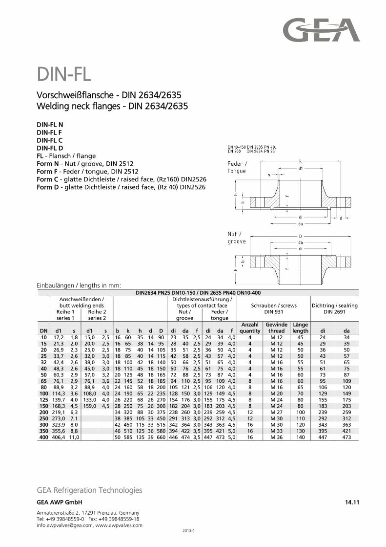
DIN-FL Vorschweißflansche - DIN 2634/2635 Welding neck flanges - DIN 2634/2635 DIN-FL N DIN-FL F DIN-FL C DIN-FL D FL - Flansch / flange Form N - Nut / groove, DIN 2512 Form F - Feder / tongue, DIN 2512 Form C - glatte Dichtleiste / raised face, (Rz160) DIN2526 Form D - glatte Dichtleiste / raised face, (Rz 40) DIN2526
Einbaulängen / lengths in mm:
DIN2634 PN25 DN10-150 / DIN 2635 PN40 DN10-400
Anschweißenden / butt welding ends
Dichtleistenausführung / types of contact face Schrauben / screws
DIN 931 Dichtring / sealring
DIN 2691
Reihe 1 series 1
Reihe 2 series 2
Nut / groove
Feder / tongue
DN d1 s d1 s b k h d D di da f di da f Anzahl
quantity Gewinde thread
Länge length di da
10 17,2 1,8 15,0 2,5 16 60 35 14 90 23 35 2,5 24 34 4,0 4 M 12 45 24 34 15 21,3 2,0 20,0 2,5 16 65 38 14 95 28 40 2,5 29 39 4,0 4 M 12 45 29 39 20 26,9 2,3 25,0 2,5 18 75 40 14 105 35 51 2,5 36 50 4,0 4 M 12 50 36 50 25 33,7 2,6 32,0 3,0 18 85 40 14 115 42 58 2,5 43 57 4,0 4 M 12 50 43 57 32 42,4 2,6 38,0 3,0 18 100 42 18 140 50 66 2,5 51 65 4,0 4 M 16 55 51 65 40 48,3 2,6 45,0 3,0 18 110 45 18 150 60 76 2,5 61 75 4,0 4 M 16 55 61 75 50 60,3 2,9 57,0 3,2 20 125 48 18 165 72 88 2,5 73 87 4,0 4 M 16 60 73 87 65 76,1 2,9 76,1 3,6 22 145 52 18 185 94 110 2,5 95 109 4,0 8 M 16 60 95 109 80 88,9 3,2 88,9 4,0 24 160 58 18 200 105 121 2,5 106 120 4,0 8 M 16 65 106 120 100 114,3 3,6 108,0 4,0 24 190 65 22 235 128 150 3,0 129 149 4,5 8 M 20 70 129 149 125 139,7 4,0 133,0 4,0 26 220 68 26 270 154 176 3,0 155 175 4,5 8 M 24 80 155 175 150 168,3 4,5 159,0 4,5 28 250 75 26 300 182 204 3,0 183 203 4,5 8 M 24 80 183 203 200 219,1 6,3 34 320 88 30 375 238 260 3,0 239 259 4,5 12 M 27 100 239 259 250 273,0 7,1 38 385 105 33 450 291 313 3,0 292 312 4,5 12 M 30 110 292 312 300 323,9 8,0 42 450 115 33 515 342 364 3,0 343 363 4,5 16 M 30 120 343 363 350 355,6 8,8 46 510 125 36 580 394 422 3,5 395 421 5,0 16 M 33 130 395 421 400 406,4 11,0 50 585 135 39 660 446 474 3,5 447 473 5,0 16 M 36 140 447 473
GEA Refrigeration Technologies
GEA AWP GmbH 14.12
Armaturenstraße 2, 17291 Prenzlau, Germany Tel: +49 39848559-0 Fax: +49 39848559-18 [email protected], www.awpvalves.com 2013-1
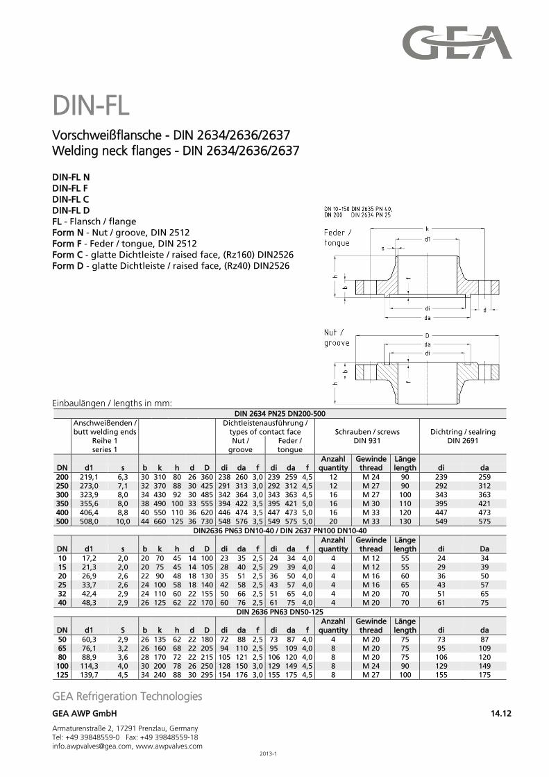
DIN-FL Vorschweißflansche - DIN 2634/2636/2637 Welding neck flanges - DIN 2634/2636/2637 DIN-FL N DIN-FL F DIN-FL C DIN-FL D FL - Flansch / flange Form N - Nut / groove, DIN 2512 Form F - Feder / tongue, DIN 2512 Form C - glatte Dichtleiste / raised face, (Rz160) DIN2526 Form D - glatte Dichtleiste / raised face, (Rz40) DIN2526
Einbaulängen / lengths in mm: DIN 2634 PN25 DN200-500
Anschweißenden / butt welding ends
Dichtleistenausführung / types of contact face Schrauben / screws
DIN 931 Dichtring / sealring
DIN 2691 Reihe 1 series 1
Nut / groove
Feder / tongue
DN d1 s b k h d D di da f di da f Anzahl
quantity Gewinde thread
Länge length di da
200 219,1 6,3 30 310 80 26 360 238 260 3,0 239 259 4,5 12 M 24 90 239 259 250 273,0 7,1 32 370 88 30 425 291 313 3,0 292 312 4,5 12 M 27 90 292 312 300 323,9 8,0 34 430 92 30 485 342 364 3,0 343 363 4,5 16 M 27 100 343 363 350 355,6 8,0 38 490 100 33 555 394 422 3,5 395 421 5,0 16 M 30 110 395 421 400 406,4 8,8 40 550 110 36 620 446 474 3,5 447 473 5,0 16 M 33 120 447 473 500 508,0 10,0 44 660 125 36 730 548 576 3,5 549 575 5,0 20 M 33 130 549 575
DIN2636 PN63 DN10-40 / DIN 2637 PN100 DN10-40
DN d1 s b k h d D di da f di da f Anzahl
quantity Gewinde thread
Länge length di Da
10 17,2 2,0 20 70 45 14 100 23 35 2,5 24 34 4,0 4 M 12 55 24 34 15 21,3 2,0 20 75 45 14 105 28 40 2,5 29 39 4,0 4 M 12 55 29 39 20 26,9 2,6 22 90 48 18 130 35 51 2,5 36 50 4,0 4 M 16 60 36 50 25 33,7 2,6 24 100 58 18 140 42 58 2,5 43 57 4,0 4 M 16 65 43 57 32 42,4 2,9 24 110 60 22 155 50 66 2,5 51 65 4,0 4 M 20 70 51 65 40 48,3 2,9 26 125 62 22 170 60 76 2,5 61 75 4,0 4 M 20 70 61 75
DIN 2636 PN63 DN50-125
DN d1 S b k h d D di da f di da f Anzahl
quantity Gewinde thread
Länge length di da
50 60,3 2,9 26 135 62 22 180 72 88 2,5 73 87 4,0 4 M 20 75 73 87 65 76,1 3,2 26 160 68 22 205 94 110 2,5 95 109 4,0 8 M 20 75 95 109 80 88,9 3,6 28 170 72 22 215 105 121 2,5 106 120 4,0 8 M 20 75 106 120 100 114,3 4,0 30 200 78 26 250 128 150 3,0 129 149 4,5 8 M 24 90 129 149 125 139,7 4,5 34 240 88 30 295 154 176 3,0 155 175 4,5 8 M 27 100 155 175
GEA Refrigeration Technologies
GEA AWP GmbH 14.13
Armaturenstraße 2, 17291 Prenzlau, Germany Tel: +49 39848559-0 Fax: +49 39848559-18 [email protected], www.awpvalves.com 2013-1
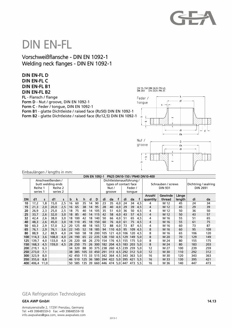
DIN EN-FL Vorschweißflansche - DIN EN 1092-1 Welding neck flanges - DIN EN 1092-1 DIN EN-FL D DIN EN-FL C DIN EN-FL B1 DIN EN-FL B2 FL - Flansch / flange Form D - Nut / groove, DIN EN 1092-1 Form C - Feder / tongue, DIN EN 1092-1 Form B1 - glatte Dichtleiste / raised face (Rz50) DIN EN 1092-1 Form B2 - glatte Dichtleiste / raised face (Rz12,5) DIN EN 1092-1 Einbaulängen / lengths in mm:
DIN EN 1092-1 PN25 DN10-150 / PN40 DN10-400
Anschweißenden / butt welding ends
Dichtleistenausführung / types of contact face Schrauben / screws
DIN 931 Dichtring / sealring
DIN 2691
Reihe 1 series 1
Reihe 2 series 2
Nut / groove
Feder / tongue
DN d1 s d1 s b k h d D di da f di da f Anzahl
quantity Gewinde thread
Länge length di da
10 17,2 1,8 15,0 2,5 16 60 35 14 90 23 35 4,0 24 34 4,5 4 M 12 45 24 34 15 21,3 2,0 20,0 2,5 16 65 38 14 95 28 40 4,0 29 39 4,5 4 M 12 45 29 39 20 26,9 2,3 25,0 2,5 18 75 40 14 105 35 51 4,0 36 50 4,5 4 M 12 50 36 50 25 33,7 2,6 32,0 3,0 18 85 40 14 115 42 58 4,0 43 57 4,5 4 M 12 50 43 57 32 42,4 2,6 38,0 3,0 18 100 42 18 140 50 66 4,0 51 65 4,5 4 M 16 55 51 65 40 48,3 2,6 45,0 3,0 18 110 45 18 150 60 76 4,0 61 75 4,5 4 M 16 55 61 75 50 60,3 2,9 57,0 3,2 20 125 48 18 165 72 88 4,0 73 87 4,5 4 M 16 60 73 87 65 76,1 2,9 76,1 3,6 22 145 52 18 185 94 110 4,0 95 109 4,5 8 M 16 60 95 109 80 88,9 3,2 88,9 4,0 24 160 58 18 200 105 121 4,0 106 120 4,5 8 M 16 65 106 120 100 114,3 3,6 108,0 4,0 24 190 65 22 235 128 150 4,5 129 149 5,0 8 M 20 70 129 149 125 139,7 4,0 133,0 4,0 26 220 68 26 270 154 176 4,5 155 175 5,0 8 M 24 80 155 175 150 168,3 4,5 159,0 4,5 28 250 75 26 300 182 204 4,5 183 203 5,0 8 M 24 80 183 203 200 219,1 6,3 34 320 88 30 375 238 260 4,5 239 259 5,0 12 M 27 100 239 259 250 273,0 7,1 38 385 105 33 450 291 313 4,5 292 312 5,0 12 M 30 110 292 312 300 323,9 8,0 42 450 115 33 515 342 364 4,5 343 363 5,0 16 M 30 120 343 363 350 355,6 8,8 46 510 125 36 580 394 422 5,0 395 421 5,5 16 M 33 130 395 421 400 406,4 11,0 50 585 135 39 660 446 474 5,0 447 473 5,5 16 M 36 140 447 473
GEA Refrigeration Technologies
GEA AWP GmbH 14.14
Armaturenstraße 2, 17291 Prenzlau, Germany Tel: +49 39848559-0 Fax: +49 39848559-18 [email protected], www.awpvalves.com 2013-1
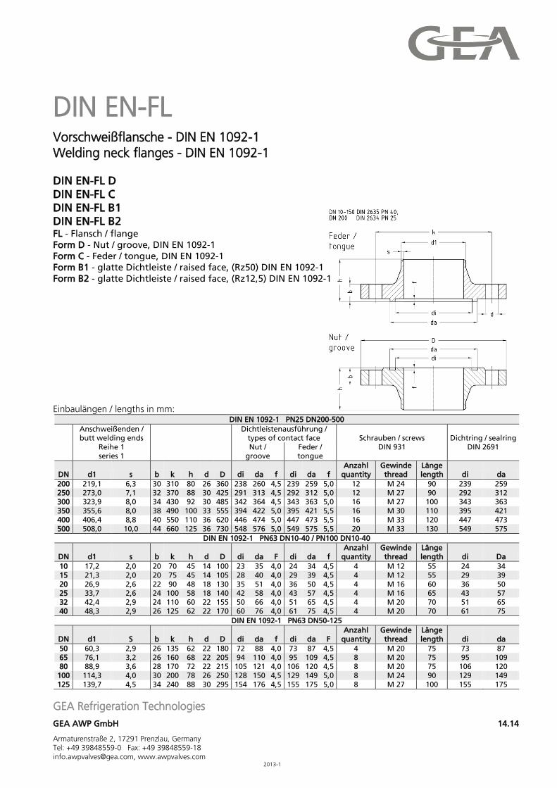
DIN EN-FL Vorschweißflansche - DIN EN 1092-1 Welding neck flanges - DIN EN 1092-1 DIN EN-FL D DIN EN-FL C DIN EN-FL B1 DIN EN-FL B2 FL - Flansch / flange Form D - Nut / groove, DIN EN 1092-1 Form C - Feder / tongue, DIN EN 1092-1 Form B1 - glatte Dichtleiste / raised face, (Rz50) DIN EN 1092-1 Form B2 - glatte Dichtleiste / raised face, (Rz12,5) DIN EN 1092-1
Einbaulängen / lengths in mm:
DIN EN 1092-1 PN25 DN200-500
Anschweißenden / butt welding ends
Dichtleistenausführung / types of contact face Schrauben / screws
DIN 931 Dichtring / sealring
DIN 2691
Reihe 1 series 1
Nut / groove
Feder / tongue
DN d1 s b k h d D di da f di da f Anzahl
quantity Gewinde thread
Länge length di da
200 219,1 6,3 30 310 80 26 360 238 260 4,5 239 259 5,0 12 M 24 90 239 259 250 273,0 7,1 32 370 88 30 425 291 313 4,5 292 312 5,0 12 M 27 90 292 312 300 323,9 8,0 34 430 92 30 485 342 364 4,5 343 363 5,0 16 M 27 100 343 363 350 355,6 8,0 38 490 100 33 555 394 422 5,0 395 421 5,5 16 M 30 110 395 421 400 406,4 8,8 40 550 110 36 620 446 474 5,0 447 473 5,5 16 M 33 120 447 473 500 508,0 10,0 44 660 125 36 730 548 576 5,0 549 575 5,5 20 M 33 130 549 575
DIN EN 1092-1 PN63 DN10-40 / PN100 DN10-40
DN d1 s b k h d D di da F di da f Anzahl
quantity Gewinde thread
Länge length di Da
10 17,2 2,0 20 70 45 14 100 23 35 4,0 24 34 4,5 4 M 12 55 24 34 15 21,3 2,0 20 75 45 14 105 28 40 4,0 29 39 4,5 4 M 12 55 29 39 20 26,9 2,6 22 90 48 18 130 35 51 4,0 36 50 4,5 4 M 16 60 36 50 25 33,7 2,6 24 100 58 18 140 42 58 4,0 43 57 4,5 4 M 16 65 43 57 32 42,4 2,9 24 110 60 22 155 50 66 4,0 51 65 4,5 4 M 20 70 51 65 40 48,3 2,9 26 125 62 22 170 60 76 4,0 61 75 4,5 4 M 20 70 61 75
DIN EN 1092-1 PN63 DN50-125
DN d1 S b k h d D di da f di da F Anzahl
quantity Gewinde thread
Länge length di da
50 60,3 2,9 26 135 62 22 180 72 88 4,0 73 87 4,5 4 M 20 75 73 87 65 76,1 3,2 26 160 68 22 205 94 110 4,0 95 109 4,5 8 M 20 75 95 109 80 88,9 3,6 28 170 72 22 215 105 121 4,0 106 120 4,5 8 M 20 75 106 120
100 114,3 4,0 30 200 78 26 250 128 150 4,5 129 149 5,0 8 M 24 90 129 149 125 139,7 4,5 34 240 88 30 295 154 176 4,5 155 175 5,0 8 M 27 100 155 175
GEA Refrigeration Technologies
GEA AWP GmbH 14.15
Armaturenstraße 2, 17291 Prenzlau, Germany Tel: +49 39848559-0 Fax: +49 39848559-18 [email protected], www.awpvalves.com 2013-1
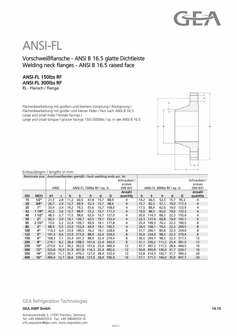
ANSI-FL Vorschweißflansche - ANSI B 16.5 glatte Dichtleiste Welding neck flanges - ANSI B 16.5 raised face ANSI-FL 150lbs RF ANSI-FL 300lbs RF FL - Flansch / flange Flächenbearbeitung mit großem und kleinem Vorsprung / Rücksprung / Flächenbearbeitung mit großer und kleiner Feder / Nut nach ANSI B 16.5 Large and small male / female facings / Large and small tongue / groove facings 150-2500lbs / sq. in see ANSI B 16.5 Einbaulängen / lengths in mm : Nominale size Anschweißenden gemäß: / butt welding ends acc. to:
ANSI ANSI-FL 150lbs RF / sq. in
Schrauben / screws
DIN 931 ANSI-FL 300lbs RF / sq. in
Schrauben / screws
DIN 931
DN INCH d1 s b k h d D Anzahl
quantity b k h d D Anzahl
quantity 15 1/2“ 21,3 2,8 11,2 60,5 47,8 15,7 88,9 4 14,2 66,5 52,3 15,7 95,2 4 20 3/4“ 26,7 2,9 12,7 69,9 52,3 15,7 98,6 4 15,7 82,5 57,1 19,0 117,3 4 25 1“ 33,4 3,4 14,2 79,2 55,6 15,7 108,0 4 17,5 88,9 62,0 19,0 123,9 4 32 1 1/4“ 42,2 3,6 15,7 88,9 57,2 15,7 117,3 4 19,0 98,5 65,0 19,0 133,3 4 40 1 1/2“ 48,3 3,7 17,5 98,6 62,0 15,7 127,0 4 20,6 114,3 68,3 22,3 155,4 4 50 2“ 60,3 3,9 19,1 120,7 63,5 19,1 152,4 4 22,3 127,0 69,8 19,0 165,1 6 65 2 1/2“ 73,0 5,2 22,4 139,7 69,9 19,1 177,8 4 25,4 149,3 76,2 22,3 190,5 8 80 3“ 88,9 5,5 23,9 152,4 69,9 19,1 190,5 4 28,4 168,1 79,2 22,3 209,5 8
100 4“ 114,3 6,0 23,9 190,5 76,2 19,1 228,6 8 31,7 200,1 85,8 22,3 254,0 8 125 5“ 141,3 6,6 23,9 215,9 88,9 22,4 254,0 8 35,0 234,9 98,5 22,3 279,4 8 150 6“ 168,3 7,1 25,4 241,3 88,9 22,4 279,4 8 36,5 269,7 98,5 22,3 317,5 12 200 8“ 219,1 8,2 28,4 298,5 101,6 22,4 342,9 8 41,1 330,2 111,2 25,4 381,0 12 250 10“ 273,0 9,3 30,2 362,0 101,6 25,4 406,4 12 47,7 387,3 117,3 28,4 444,5 16 300 12“ 323,8 10,3 31,8 431,8 114,3 25,4 482,6 12 50,8 450,8 130,0 31,7 520,7 16 350 14“ 355,6 11,1 35,1 476,3 127,0 28,4 533,4 12 53,8 514,3 142,7 31,7 584,2 20 400 16“ 406,4 12,7 36,6 539,8 127,0 28,4 596,9 16 57,1 571,5 146,0 35,0 647,7 20
GEA Refrigeration Technologies
GEA AWP GmbH 14.16
Armaturenstraße 2, 17291 Prenzlau, Germany Tel: +49 39848559-0 Fax: +49 39848559-18 [email protected], www.awpvalves.com 2013-1
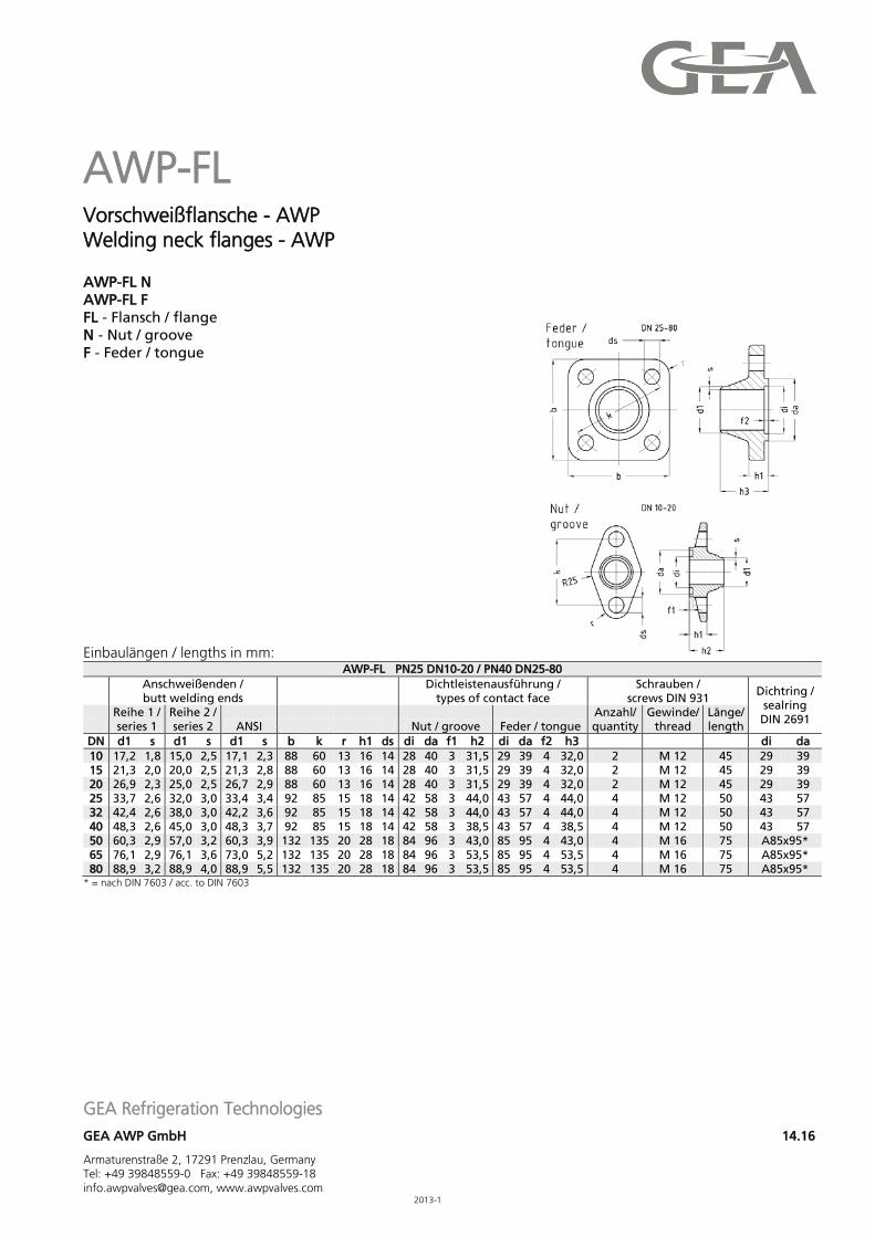
AWP-FL Vorschweißflansche - AWP Welding neck flanges - AWP AWP-FL N AWP-FL F FL - Flansch / flange N - Nut / groove F - Feder / tongue Einbaulängen / lengths in mm:
AWP-FL PN25 DN10-20 / PN40 DN25-80
Anschweißenden / butt welding ends
Dichtleistenausführung / types of contact face
Schrauben / screws DIN 931
Dichtring / sealring DIN 2691
Reihe 1 / series 1
Reihe 2 / series 2 ANSI Nut / groove Feder / tongue
Anzahl/ quantity
Gewinde/ thread
Länge/ length
DN d1 s d1 s d1 s b k r h1 ds di da f1 h2 di da f2 h3 di da 10 17,2 1,8 15,0 2,5 17,1 2,3 88 60 13 16 14 28 40 3 31,5 29 39 4 32,0 2 M 12 45 29 39 15 21,3 2,0 20,0 2,5 21,3 2,8 88 60 13 16 14 28 40 3 31,5 29 39 4 32,0 2 M 12 45 29 39 20 26,9 2,3 25,0 2,5 26,7 2,9 88 60 13 16 14 28 40 3 31,5 29 39 4 32,0 2 M 12 45 29 39 25 33,7 2,6 32,0 3,0 33,4 3,4 92 85 15 18 14 42 58 3 44,0 43 57 4 44,0 4 M 12 50 43 57 32 42,4 2,6 38,0 3,0 42,2 3,6 92 85 15 18 14 42 58 3 44,0 43 57 4 44,0 4 M 12 50 43 57 40 48,3 2,6 45,0 3,0 48,3 3,7 92 85 15 18 14 42 58 3 38,5 43 57 4 38,5 4 M 12 50 43 57 50 60,3 2,9 57,0 3,2 60,3 3,9 132 135 20 28 18 84 96 3 43,0 85 95 4 43,0 4 M 16 75 A85x95* 65 76,1 2,9 76,1 3,6 73,0 5,2 132 135 20 28 18 84 96 3 53,5 85 95 4 53,5 4 M 16 75 A85x95* 80 88,9 3,2 88,9 4,0 88,9 5,5 132 135 20 28 18 84 96 3 53,5 85 95 4 53,5 4 M 16 75 A85x95*
* = nach DIN 7603 / acc. to DIN 7603
GEA Refrigeration Technologies
GEA AWP GmbH 14.17
Armaturenstraße 2, 17291 Prenzlau, Germany Tel: +49 39848559-0 Fax: +49 39848559-18 [email protected], www.awpvalves.com 2013-1
Anhang / appendix Rechtlicher Hinweis Legal Note Rechtlicher Hinweis GEA AWP Armaturen sind gemäß den GEA AWP Betriebsvorschriften zu handhaben. Die in den Betriebsvorschriften genannten Sicherheitshinweise sind zu beachten. Es liegt eine Gefahrenanalyse für GEA AWP Armaturen vor. Die Handhabung der GEA AWP Armaturen hat ausschließlich durch autorisierte Personen zu erfolgen. Dabei sind die Hinweise zum Gebrauch persönlicher Schutzausrüstung (PSA) zu beachten. Die GEA AWP Armaturen sind bestimmungsgemäß einzusetzen. Dieser Katalog wurde sorgfältig erstellt und geprüft, kann aber dennoch Fehler enthalten. Die im Katalog gemachten technischen Angaben sind keine vertraglich zugesicherten Eigenschaften. Die technischen Angaben sind nur dann verbindlich, wenn Sie von uns schriftlich bestätigt wurden. Wir behalten uns technische Änderungen vor. Weitere Informationen zu unseren Konformitätserklärungen, Betriebsvorschriften, Berechnungsprogramm und den allgemeinen Geschäftsbedingungen finden Sie auf unserer Internetseite www.awpvalves.com im Register Tools/Downloads. Es gelten unsere allgemeinen Geschäftsbedingungen. Legal Note GEA AWP valves should be handled in accordance with the GEA AWP operating instructions. The safety notes mentioned inside the operating instructions have to be considered. A risk analysis for GEA AWP valves is available. To handle GEA AWP valves is permitted for authorized personnel only. The advice to use personnel protective equipment (PPE) has to be considered. GEA AWP valves have to be used as intended. This catalogue had been established carefully and had been reviewed in detail, nevertheless it might contain mistakes. The catalogue data is not contractually-guaranteed. The catalogue data is mandatory after confirmed in a written form by us. Technical data are subject to change. Other information to our declaration of conformity, operating instructions, calculation program and the standard business terms finds them on our Internet page www.awpvalves.com in the register Tools/Downloads. Our standard business terms are valid.
We live our values.
Excellence ● Passion ● Integrity ● Responsibility ● GEA-versity GEA Group is a global engineering company with multi-billion euro sales and operations in more than 50 countries. Founded in 1881, the company is one of the largest providers of innovative equipment and
process technology. GEA Group is listed in the STOXX® Europe 600 index.
GEA Refrigeration Technologies
GEA AWP GmbH
Armaturenstraße 2, 17291 Prenzlau, Germany Tel: +49 39848559-0 Fax: +49 39848559-18 [email protected], www.awpvalves.com
© G
EA. A
ll ri
ghts
res
erve
d. 0
1/2
012
-RT-
00
2-0
90
0-D
E/U
S-EU
- Su
bje
ct t
o m
odific
atio
n