Embed Size (px)
Citation preview
SHARK-DRILL2
2
SHARK-Drill² SHARK-Drill2 SHARK-Drill2• Systemvorstellung • System introduction • Caratteristiche del sistema 122 – 123• Bezeichnungssystem • Designation system • Systema di numerazione 124• Werkzeugauswahl • Tool shank options • Tipologie di attacco utensile 125• Trägerwerkzeuge • Drill holder • Corpo punta 126 – 129• Schneideinsätze • Inserts • Inserti 130 – 137
– Geometriebeschreibung – Geometry description – Descrizione delle Geometrie 130– Sortenbeschreibung – Grade description – Descrizione delle Qualità 131
• Ersatzteile • Spare parts • Ricambi 138• Schnittwerte • Cutting data • Parametri di taglio 139 – 141• Anwendungshinweise • Application reference • Suggerimenti tecnici 142 – 145
2
2
122 ARNO®-Werkzeuge | Bohren | Drilling | Foratura
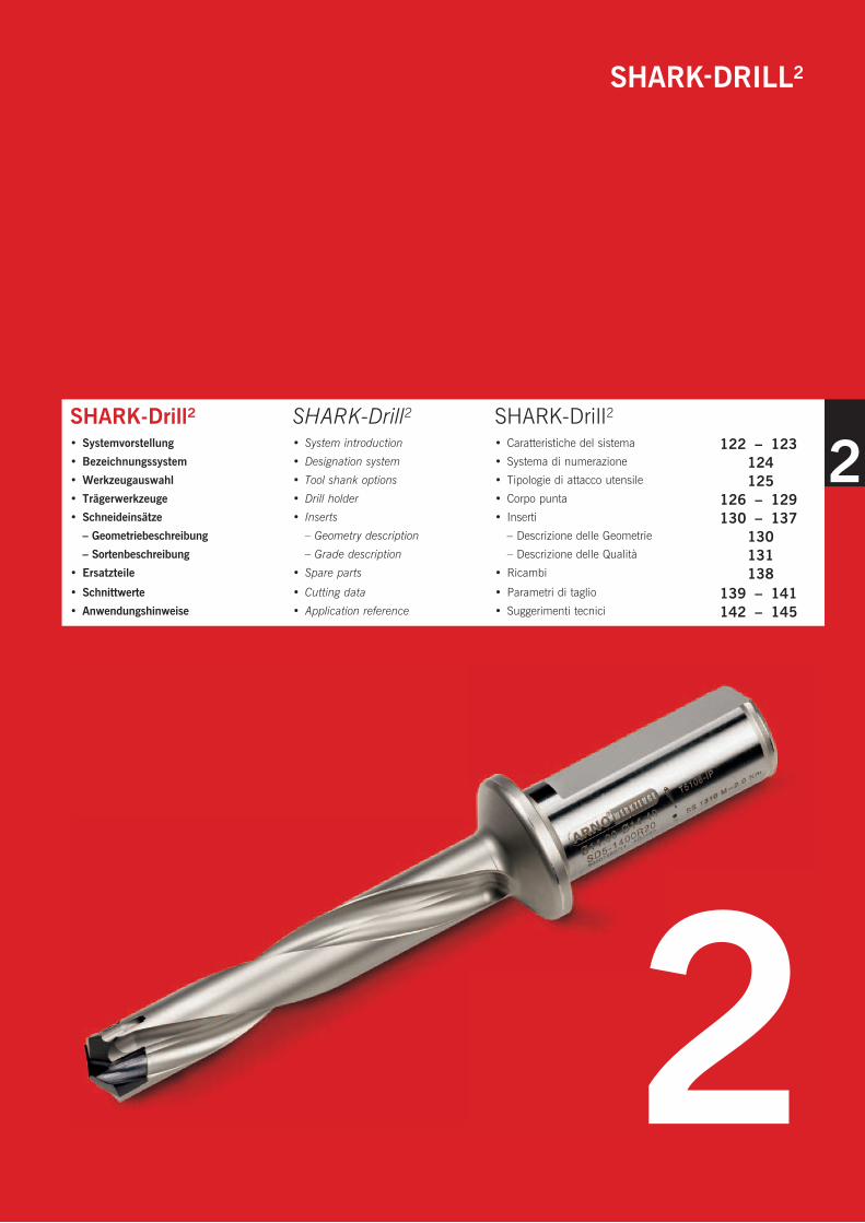
ARNO Schneidplattenbohrer SHARK-Drill2ARNO Flanged holders SHARK-Drill2ARNO Corpo punta SHARK-Drill2
HM-Schneideinsatz in beschichteter und unbeschichteter Ausführung. Ø 14 mm bis Ø 32 mm Carbide inserts either coated or uncoated. Ø 14 mm to Ø 32 mm drill diameter capability
Inserti in Metallo Duro micrograna, nudi e rivestiti da Ø 14 mm a Ø 32 mm
Optimierter KühlmittelaustrittOptimized coolant outlet
Canali di adduzione refrigerante
Verbreiterte Spankammern zur Aufnahme eines höheren SpänevolumensEnhanced swarf chambers for more swarf volume
Innovativa forma delle eliche per un maggiore volume truciolo
TORX-Plus® Schraube mit Niederzugseffekt der BohrplatteTORX-Plus® screw with more locking strength
TORX-Plus® vite con una incrementata forza di serraggio
Einfache Identifi kation durch umfangreiche Werkzeugbeschriftung:• Bezeichnung• Ø-Bereich• Schraubenanzugsmoment• Ersatzteile und ZubehörEasy identifi cation information:
• Description• Diameter range• Torque setting• Spare part
Dati per un facile riconoscimento:
• Descrizione• Gammadiametridilavoro• Forzadiserraggiorichiesta• Codiciricambi
Optimierter Auslauf der Spankammer im Bund Swarf chamber run out into shoulder
Dimensione e forma ottimizzata delle eliche di scarico truciolo per una ridotta lunghezza totale
Beschichteter Halter für optimale Spanabfuhr und lange LebensdauerCoated holder for improved swarf evacuation and longer tool life
Speciale rivestimento del corpo punta per migliore scorrimento del truciolo e prolungata vita utensile
Großer Bund-Ø: Geschliffen, für optimale Plananlage im HalterLarge location shoulder,ground for optimum holder location
Flangia di diametro maggiorato,rettifi cata per un migliore posizionamento e stabilità
Schaft nach DIN ISO 9766 mit durchgehender Spannfl ächeShank to DIN ISO 9766 with fl at
Codolo DIN ISO 9766 con superfi cie di bloccaggio continua
SystemvorstellungIntroductionCaratteristiche del sistema
2
123 ARNO®-Werkzeuge | Bohren | Drilling | Foratura
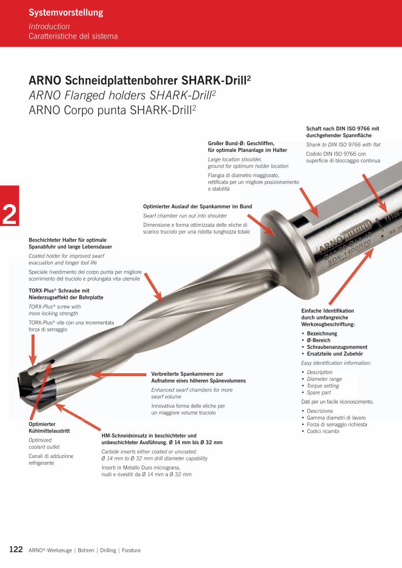
Höchste Bohrperformance durch neuartige Geometrie mit hervorragender SpankontrolleMaximum drilling performance due to new geometry with excellent swarf control
Utensile sviluppato appositamente per elevate prestazioni di taglio • Flexibles System – ein Halter für mehrere Bohrdurchmesser • Stabile und sichere Klemmung der Bohrplatte durch TORX-Plus® Schraube • Schaft nach DIN ISO 9766 mit durchgehender Spannfläche • Durchmesserbereich 14 mm bis 32 mm • In 2 x D, 3 x D, 5 x D und 8 x D ab Lager verfügbar • Stabiler Bund zur Aufnahme hoher Axialkräfte • Ein optimierter Auslauf der Spankammer spart Auskraglänge • Bewährter Spitzenanschliff für sehr gute Zentriereigenschaften und Bohrungsqualitäten • HM-Schneideinsätze in beschichteter (PVD–TiAlN) und unbeschichteter Ausführung
zur Bearbeitung von Stahl, rostfreien Stählen, NE-Metallen und Gusswerkstoffen• Plattenwechsel unkompliziert und schnell, selbst im eingebauten Zustand möglich
• Flexible system – one holder for different drill diameters
• Robust and secure insert clamping with TORX-Plus® screws
• Shank to DIN ISO 9766 with full length flat
• Drill diameter range 14 mm – 32 mm
• Available for 2 x D, 3 x D, 5 x D and 8 x D drill depth
• Strong shank design for absorbing high axial forces
• The optimised run out of the swarf chambers reduces drill overhang length
• Improved drill point design for excellent centring and hole quality
• Coated (PVD-TiAlN) and un-coated carbide drilling inserts for machining steel, stainless steel, non-ferrous materials and cast materials
• Insert replacement uncomplicated and quick, can be changed whilst still in the machine
•Sistemaflessibile–unosteloperpiùdiametridilavoro
•AccoppiamentoinsertoprecisoerobustoconviteTORX-Plus®
•StelocilindricosecondonormaDINISO9766conpianodibloccaggio
•Gammadiametri14mm–32mm
•Disponibileinversione2xD,3xD,5xDe8xD
•Steloinacciaiodautensilidaaltissimaqualitàeflangiastudiatapercontrollare al meglio le forze di taglio
•Laspecialeformadelleelicheèstudiataancheperridurrela lunghezza totale ed aumentare la rigidità della punta in lavoro
•Migliorataformadelnocciolodicentraggioperuna eccellente foratura e finitura foro
•RivestimentiPVD-TiAlNperlaforaturadiacciai,stampati,acciai inossidabili, inserti in metallo duro micrograna per forare materiali non ferrosi o ghise
•Formadeipianidiappoggioinsertoampipercontrastarele elevate forze assiali e la durata della sede nel tempo
Innere Kühlmittelzufuhr Through tool coolant
Adduzione interna
SHARK-DRILL2
2
124 ARNO®-Werkzeuge | Bohren | Drilling | Foratura
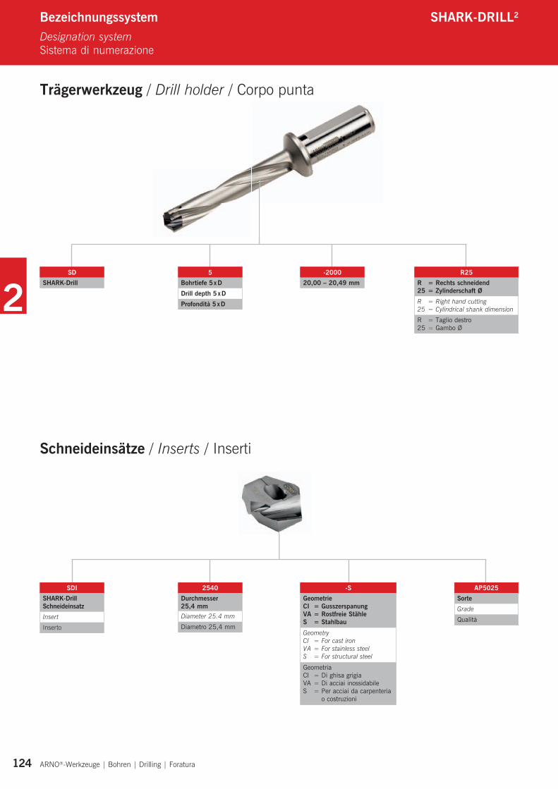
Bezeichnungssystem SHARK-DRILL2
Designation systemSistema di numerazione
Trägerwerkzeug / Drill holder / Corpo punta
Schneideinsätze / Inserts / Inserti
SDSHARK-Drill
SDISHARK-Drill SchneideinsatzInsert
Inserto
5Bohrtiefe 5 x DDrill depth 5 x DProfondità 5 x D
2540Durchmesser25,4 mmDiameter 25.4 mm
Diametro 25,4 mm
-200020,00 – 20,49 mm
AP5025SorteGrade
Qualità
-SGeometrieCI = GusszerspanungVA = Rostfreie StähleS = StahlbauGeometryCI = For cast ironVA = For stainless steelS = For structural steel
GeometriaCI = Di ghisa grigiaVA = Di acciai inossidabileS = Per acciai da carpenteria
o costruzioni
R25R = Rechts schneidend25 = Zylinderschaft ØR = Right hand cutting25 = Cylindrical shank dimension
R = Taglio destro25 = Gambo Ø
2
125 ARNO®-Werkzeuge | Bohren | Drilling | Foratura
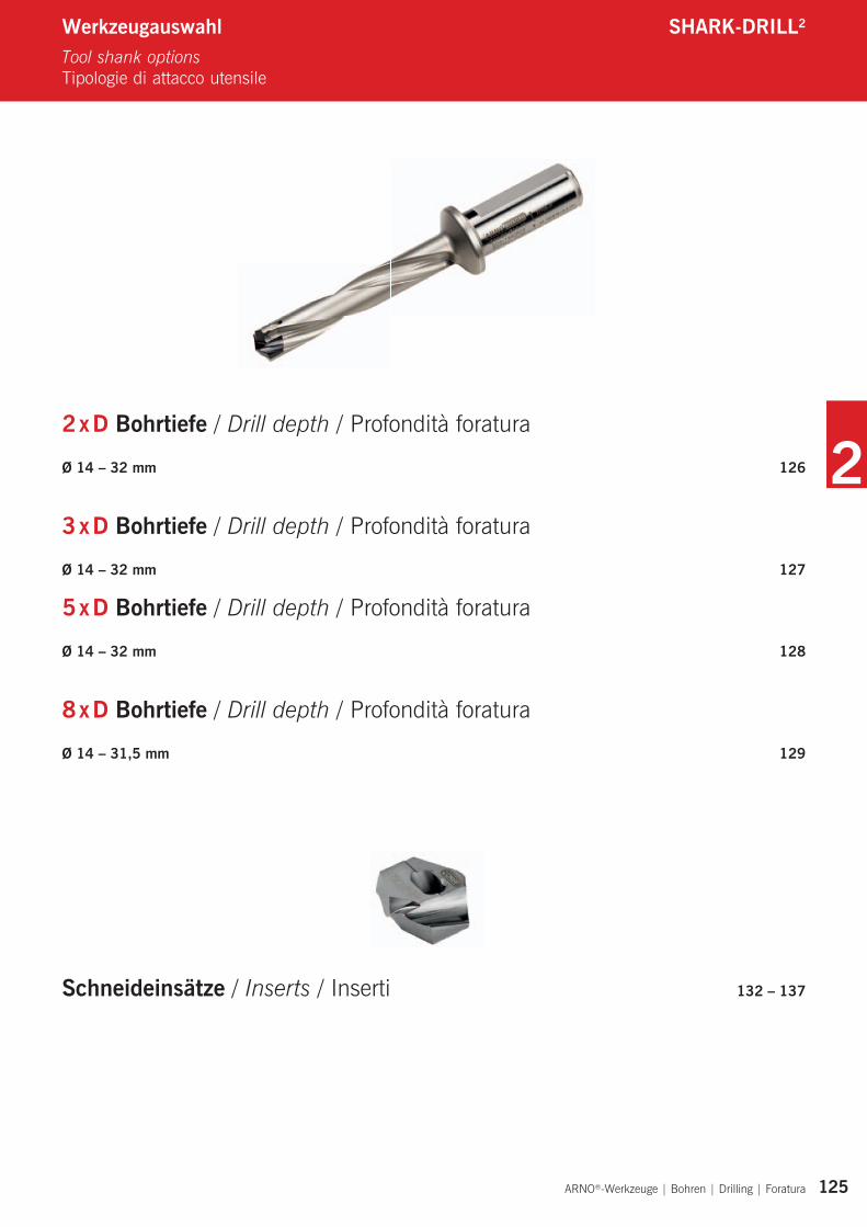
Werkzeugauswahl SHARK-DRILL2
Tool shank optionsTipologie di attacco utensile
2 x D Bohrtiefe / Drill depth / Profondità foratura
Ø 14 – 32 mm 126
3 x D Bohrtiefe / Drill depth / Profondità foratura
Ø 14 – 32 mm 127
5 x D Bohrtiefe / Drill depth / Profondità foratura
Ø 14 – 32 mm 128
8 x D Bohrtiefe / Drill depth / Profondità foratura
Ø 14 – 31,5 mm 129
Schneideinsätze / Inserts / Inserti 132 – 137
2
ARNO®-Werkzeuge | Bohren | Drilling | Foratura Alle Angaben in mm / Dimensions in mm / Tutte le dimensioni in mm 126
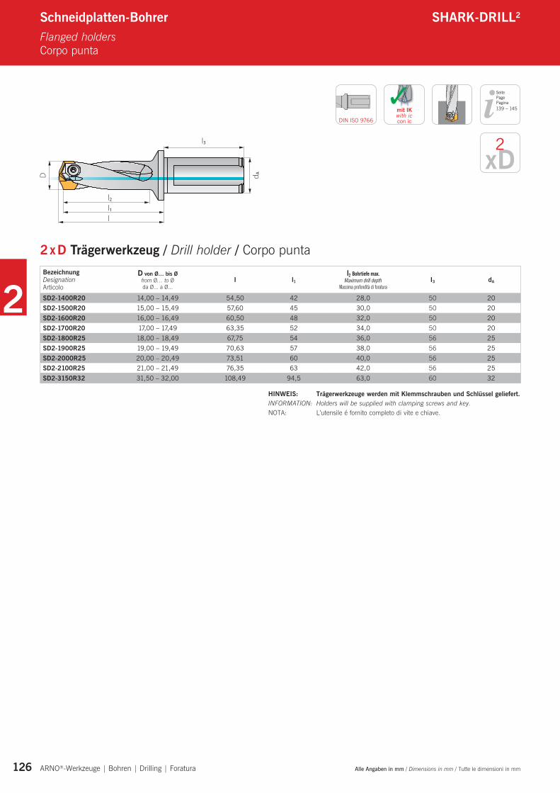
Schneidplatten-Bohrer SHARK-DRILL2
Flanged holders Corpo punta
Seite PagePagina
DIN ISO 9766
xD2
2 x D Trägerwerkzeug / Drill holder / Corpo puntaBezeichnung Designation Articolo
D von Ø… bis Ø from Ø… to Ø da Ø... a Ø...
I l1I2 Bohrtiefe max.
Maximum drill depth Massima profondità di foratura
I3 dA
SD2-1400R20 14,00 – 14,49 54,50 42 28,0 50 20SD2-1500R20 15,00 – 15,49 57,60 45 30,0 50 20SD2-1600R20 16,00 – 16,49 60,50 48 32,0 50 20SD2-1700R20 17,00 – 17,49 63,35 52 34,0 50 20SD2-1800R25 18,00 – 18,49 67,75 54 36,0 56 25SD2-1900R25 19,00 – 19,49 70,63 57 38,0 56 25SD2-2000R25 20,00 – 20,49 73,51 60 40,0 56 25SD2-2100R25 21,00 – 21,49 76,35 63 42,0 56 25SD2-3150R32 31,50 – 32,00 108,49 94,5 63,0 60 32
✓mit IKwith iccon ic
HINWEIS: Trägerwerkzeuge werden mit Klemmschrauben und Schlüssel geliefert.INFORMATION: Holders will be supplied with clamping screws and key.NOTA: L’utensile é fornito completo di vite e chiave.
139 – 145
2
Alle Angaben in mm / Dimensions in mm / Tutte le dimensioni in mm ARNO®-Werkzeuge | Bohren | Drilling | Foratura 127
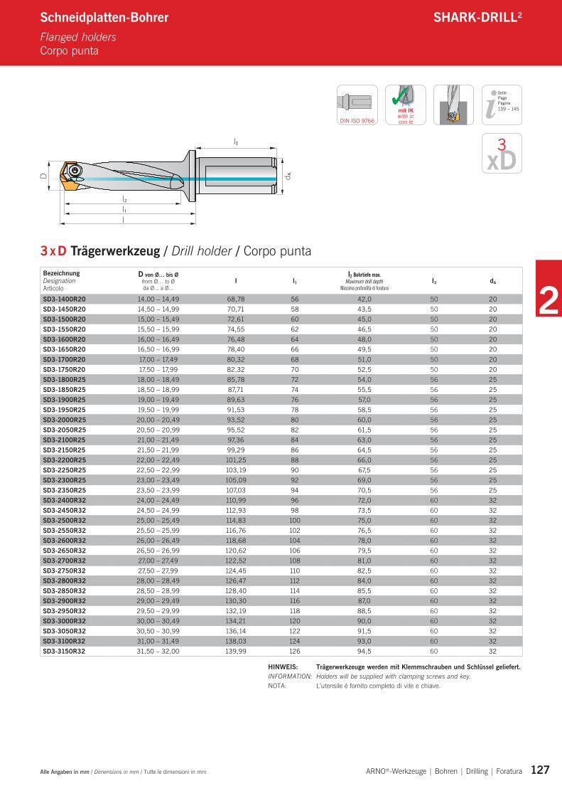
Schneidplatten-Bohrer SHARK-DRILL2
Flanged holders Corpo punta
Seite PagePagina
DIN ISO 9766
xD3
3 x D Trägerwerkzeug / Drill holder / Corpo puntaBezeichnung Designation Articolo
D von Ø… bis Ø from Ø… to Ø da Ø... a Ø...
I l1I2 Bohrtiefe max.
Maximum drill depth Massima profondità di foratura
I3 dA
SD3-1400R20 14,00 – 14,49 68,78 56 42,0 50 20SD3-1450R20 14,50 – 14,99 70,71 58 43,5 50 20SD3-1500R20 15,00 – 15,49 72,61 60 45,0 50 20SD3-1550R20 15,50 – 15,99 74,55 62 46,5 50 20SD3-1600R20 16,00 – 16,49 76,48 64 48,0 50 20SD3-1650R20 16,50 – 16,99 78,40 66 49,5 50 20SD3-1700R20 17,00 – 17,49 80,32 68 51,0 50 20SD3-1750R20 17,50 – 17,99 82,32 70 52,5 50 20SD3-1800R25 18,00 – 18,49 85,78 72 54,0 56 25SD3-1850R25 18,50 – 18,99 87,71 74 55,5 56 25SD3-1900R25 19,00 – 19,49 89,63 76 57,0 56 25SD3-1950R25 19,50 – 19,99 91,53 78 58,5 56 25SD3-2000R25 20,00 – 20,49 93,52 80 60,0 56 25SD3-2050R25 20,50 – 20,99 95,52 82 61,5 56 25SD3-2100R25 21,00 – 21,49 97,36 84 63,0 56 25SD3-2150R25 21,50 – 21,99 99,29 86 64,5 56 25SD3-2200R25 22,00 – 22,49 101,25 88 66,0 56 25SD3-2250R25 22,50 – 22,99 103,19 90 67,5 56 25SD3-2300R25 23,00 – 23,49 105,09 92 69,0 56 25SD3-2350R25 23,50 – 23,99 107,03 94 70,5 56 25SD3-2400R32 24,00 – 24,49 110,99 96 72,0 60 32SD3-2450R32 24,50 – 24,99 112,93 98 73,5 60 32SD3-2500R32 25,00 – 25,49 114,83 100 75,0 60 32SD3-2550R32 25,50 – 25,99 116,76 102 76,5 60 32SD3-2600R32 26,00 – 26,49 118,68 104 78,0 60 32SD3-2650R32 26,50 – 26,99 120,62 106 79,5 60 32SD3-2700R32 27,00 – 27,49 122,52 108 81,0 60 32SD3-2750R32 27,50 – 27,99 124,45 110 82,5 60 32SD3-2800R32 28,00 – 28,49 126,47 112 84,0 60 32SD3-2850R32 28,50 – 28,99 128,40 114 85,5 60 32SD3-2900R32 29,00 – 29,49 130,30 116 87,0 60 32SD3-2950R32 29,50 – 29,99 132,19 118 88,5 60 32SD3-3000R32 30,00 – 30,49 134,21 120 90,0 60 32SD3-3050R32 30,50 – 30,99 136,14 122 91,5 60 32SD3-3100R32 31,00 – 31,49 138,03 124 93,0 60 32SD3-3150R32 31,50 – 32,00 139,99 126 94,5 60 32
✓mit IKwith iccon ic
HINWEIS: Trägerwerkzeuge werden mit Klemmschrauben und Schlüssel geliefert.INFORMATION: Holders will be supplied with clamping screws and key.NOTA: L’utensile é fornito completo di vite e chiave.
139 – 145
2
ARNO®-Werkzeuge | Bohren | Drilling | Foratura Alle Angaben in mm / Dimensions in mm / Tutte le dimensioni in mm 128
Schneidplatten-Bohrer SHARK-DRILL2
Flanged holders Corpo punta
Seite PagePagina
DIN ISO 9766
xD5
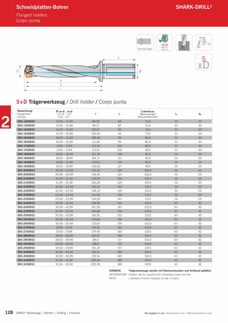
5 x D Trägerwerkzeug / Drill holder / Corpo punta
✓mit IKwith iccon ic
Bezeichnung Designation Articolo
D von Ø… bis Ø from Ø… to Ø da Ø... a Ø...
I l1I2 Bohrtiefe max.
Maximum drill depth Massima profondità di foratura
I3 dA
SD5-1400R20 14,00 – 14,49 96,78 84 70,0 50 20SD5-1450R20 14,50 – 14,99 99,71 87 72,5 50 20SD5-1500R20 15,00 – 15,49 102,61 90 75,0 50 20SD5-1550R20 15,50 – 15,99 105,55 93 77,5 50 20SD5-1600R20 16,00 – 16,49 108,48 96 80,0 50 20SD5-1650R20 16,50 – 16,99 111,40 99 82,5 50 20SD5-1700R20 17,00 – 17,49 114,32 102 85,0 50 20SD5-1750R20 17,50 – 17,99 117,32 105 87,5 50 20SD5-1800R25 18,00 – 18,49 121,78 108 90,0 56 25SD5-1850R25 18,50 – 18,99 124,71 111 92,5 56 25SD5-1900R25 19,00 – 19,49 127,63 114 95,0 56 25SD5-1950R25 19,50 – 19,99 130,53 117 97,5 56 25SD5-2000R25 20,00 – 20,49 133,52 120 100,0 56 25SD5-2050R25 20,50 – 20,99 136,45 123 102,5 56 25SD5-2100R25 21,00 – 21,49 139,36 126 105,0 56 25SD5-2150R25 21,50 – 21,99 142,29 129 107,5 56 25SD5-2200R25 22,00 – 22,49 145,25 132 110,0 56 25SD5-2250R25 22,50 – 22,99 148,19 135 112,5 56 25SD5-2300R25 23,00 – 23,49 151,09 138 115,0 56 25SD5-2350R25 23,50 – 23,99 154,03 141 117,5 56 25SD5-2400R32 24,00 – 24,49 158,99 144 120,0 60 32SD5-2450R32 24,50 – 24,99 161,93 147 122,5 60 32SD5-2500R32 25,00 – 25,49 164,83 150 125,0 60 32SD5-2550R32 25,50 – 25,99 167,76 153 127,5 60 32SD5-2600R32 26,00 – 26,49 170,68 156 130,0 60 32SD5-2650R32 26,50 – 26,99 173,62 159 132,5 60 32SD5-2700R32 27,00 – 27,49 176,52 162 135,0 60 32SD5-2750R32 27,50 – 27,99 179,45 165 137,5 60 32SD5-2800R32 28,00 – 28,49 182,47 168 140,0 60 32SD5-2850R32 28,50 – 28,99 185,4 171 142,5 60 32SD5-2900R32 29,00 – 29,49 188,3 174 145,0 60 32SD5-2950R32 29,50 – 29,99 191,19 177 147,5 60 32SD5-3000R32 30,00 – 30,49 194,21 180 150,0 60 32SD5-3050R32 30,50 – 30,99 197,14 183 152,5 60 32SD5-3100R32 31,00 – 31,49 200,03 186 155,0 60 32SD5-3150R32 31,50 – 32,00 202,99 189 157,5 60 32
HINWEIS: Trägerwerkzeuge werden mit Klemmschrauben und Schlüssel geliefert.INFORMATION: Holders will be supplied with clamping screws and key.NOTA: L’utensile é fornito completo di vite e chiave.
139 – 145
2
Alle Angaben in mm / Dimensions in mm / Tutte le dimensioni in mm ARNO®-Werkzeuge | Bohren | Drilling | Foratura 129
Schneidplatten-Bohrer SHARK-DRILL2
Flanged holders Corpo punta
Seite PagePagina
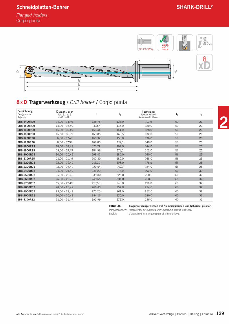
8 x D Trägerwerkzeug / Drill holder / Corpo punta
DIN ISO 9766
xD8
✓mit IKwith iccon ic
Bezeichnung Designation Articolo
D von Ø… bis Ø from Ø… to Ø da Ø... a Ø...
I l1I2 Bohrtiefe max.
Maximum drill depth Massima profondità di foratura
I3 dA
SD8-1400R20 14,00 – 14,49 138,75 126,0 112,0 50 20SD8-1500R20 15,00 – 15,49 147,57 135,0 120,0 50 20SD8-1600R20 16,00 – 16,49 156,44 144,0 128,0 50 20SD8-1650R20 16,50 – 16,99 160,86 148,5 132,0 50 20SD8-1700R20 17,00 – 17,49 165,32 153,0 136,0 50 20SD8-1750R20 17,50 – 17,99 169,80 157,5 140,0 50 20SD8-1800R25 18,00 – 18,49 175,71 162,0 144,0 56 25SD8-1900R25 19,00 – 19,49 184,58 171,0 152,0 56 25SD8-2000R25 20,00 – 20,49 193,47 180,0 160,0 56 25SD8-2100R25 21,00 – 21,49 202,30 189,0 168,0 56 25SD8-2200R25 22,00 – 22,49 211,20 198,0 176,0 56 25SD8-2300R25 23,00 – 23,49 220,04 207,0 184,0 56 25SD8-2400R32 24,00 – 24,49 231,20 216,0 192,0 60 32SD8-2500R32 25,00 – 25,49 239,80 225,0 200,0 60 32SD8-2600R32 26,00 – 26,49 248,65 234,0 208,0 60 32SD8-2700R32 27,00 – 27,49 257,50 243,0 216,0 60 32SD8-2800R32 28,00 – 28,49 266,43 252,0 224,0 60 32SD8-2900R32 29,00 – 29,49 275,25 261,0 232,0 60 32SD8-3000R32 30,00 – 30,49 284,16 270,0 240,0 60 32SD8-3100R32 31,00 – 31,49 292,99 279,0 248,0 60 32
HINWEIS: Trägerwerkzeuge werden mit Klemmschrauben und Schlüssel geliefert.INFORMATION: Holders will be supplied with clamping screws and key.NOTA: L’utensile é fornito completo di vite e chiave.
139 – 145
2
130 ARNO®-Werkzeuge | Bohren | Drilling | Foratura
Anwendungshinweise ARNO® AKBApplication reference Applicazioni
Geometriebeschreibung SHARK-DRILL2
Geometry description Descrizione delle Geometrie
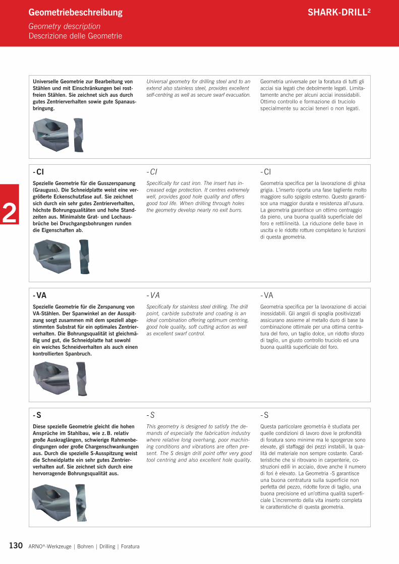
- S Diese spezielle Geometrie gleicht die hohen Ansprüche im Stahlbau, wie z. B. relativ große Auskraglängen, schwierige Rahmenbe-dingungen oder große Chargenschwankungen aus. Durch die spezielle S-Ausspitzung weist die Schneidplatte ein sehr gutes Zentrier-verhalten auf. Sie zeichnet sich durch eine hervorragende Bohrungsqualität aus.
- S This geometry is designed to satisfy the de-mands of especially the fabrication industry where relative long overhang, poor machin-ing conditions and vibrations are often pre-sent. The S design drill point offer very good tool centring and also excellent hole quality.
- S Questa particolare geometria è studiata per quelle condizioni di lavoro dove le profondità di foratura sono minime ma le sporgenze sono elevate, gli staffaggi dei pezzi instabili, la qua-lità del materiale non sempre costante. Carat-teristiche che si ritrovano in carpenterie, co-struzioni edili in acciaio, dove anche il numero di fori è elevato. La Geometria -S garantisce una buona centratura sulla superficie non perfetta del pezzo, ridotte forze di taglio, una buona precisione ed un’ottima qualità superfi-ciale L’incremento della vita inserto completa le caratteristiche di questa geometria.
- VA Spezielle Geometrie für die Zer spanung von VA-Stählen. Der Spanwinkel an der Ausspit-zung sorgt zusammen mit dem speziell abge-stimmten Substrat für ein optimales Zentrier-verhalten. Die Bohrungsqualität ist gleichmä-ßig und gut, die Schneidplatte hat sowohl ein weiches Schneidverhalten als auch einen kontrollierten Spanbruch.
- VASpecifically for stainless steel drilling. The drill point, carbide substrate and coating is an ideal combination offering optimum centring, good hole quality, soft cutting action as well as excellent swarf control.
- VA Geometria specifica per la lavorazione di acciai inossidabili. Gli angoli di spoglia positivizzati assicurano assieme al metallo duro di base la combinazione ottimale per una ottima centra-tura del foro, un taglio dolce, un ridotto sforzo di taglio, un giusto controllo truciolo ed una buona qualità superficiale del foro.
Universelle Geometrie zur Be arbeitung von Stählen und mit Einschränkungen bei rost-freien Stählen. Sie zeichnet sich aus durch gutes Zentrierverhalten sowie gute Spanaus-bringung.
Universal geometry for drilling steel and to an extend also stainless steel, provides excellent self-centring as well as secure swarf evacuation.
Geometria universale per la foratura di tutti gli acciai sia legati che debolmente legati. Limita-tamente anche per alcuni acciai inossidabili. Ottimo controllo e formazione di truciolo specialmente su acciai teneri o non legati.
- CI Spezielle Geometrie für die Gusszerspanung (Grauguss). Die Schneidplatte weist eine ver-größerte Eckenschutzfase auf. Sie zeichnet sich durch ein sehr gutes Zentrierverhalten, höchste Bohrungqualitäten und hohe Stand-zeiten aus. Minimalste Grat- und Lochaus-brüche bei Druchgangsbohrungen runden die Eigenschaften ab.
- CI Specifically for cast iron. The insert has in-creased edge protection. It centres extremely well, provides good hole quality and offers good tool life. When drilling through holes the geometry develop nearly no exit burrs.
- CI Geometria specifica per la lavorazione di ghisa grigia. L’inserto riporta una fase tagliente molto maggiore sullo spigolo esterno. Questo garanti-sce una maggior durata e resistenza all’usura. La geometria garantisce un ottimo centraggio da pieno, una buona qualità superficiale del foro e rettilineità. La riduzione delle bave in uscita e le ridotte rotture completano le funzioni di questa geometria.
2
131 ARNO®-Werkzeuge | Bohren | Drilling | Foratura
Hartmetall beschichtet / Carbide grade coated / Metallo duro rivestito
Hartmetall unbeschichtet / Carbide grade uncoated / Metallo duro non rivestito
PVD-Mehrlagenbeschichtung, HM-Feinkorn. Das Hauptanwendungsgebiet dieser Sorte ist die Bearbeitung von Stahl. In der Nebenan-wendung ist sie auch geeignet für die Bearbei-tung von rostfreien Stählen und Gusswerk-stoffen. Eine sehr universell einsetzbare Sorte mit hoher Hitze- und Oxidationsbeständigkeit.
PVD-Multilayer coating, fine grain carbide. The main application area for this grade is the machining of steel. Also suitable for machining stainless steel and cast iron. A very universal grade with high temperature and oxygenation resistance.
Metallo duro micrograna, rivestimento multistrato PVD TiAlN. Grado studiato per lavorare materiali acciai. Idoneo anche alla lavorazione di acciai inossidabili. Un grado universale molto resistente alle elevate temperature ed alla ossidazione.
Durch das harte Substrat eignet sich diese Sorte besonders zur Be arbeitung von Eisen-guss, auch bei harten Gusskrusten und unregel mäßigen Spantiefen. Sie besitzt eine exzellente Verschleißfestigkeit und eine gerin-ge Neigung zur Aufbauschneidenbildung.
The hard substrate is especially suitable for cast materials also hard cast and unusual drill depths. The grade is very wear resistant as well as resistant to build up edge.
Qualità caratterizzata dalla elavata durezza e resistenza all’usura. Rivestimento specifico per una ottima resistenza alle alte temperature e per la lavorazione di Ghise grigie anche con croste.
Sorte für die Bearbeitung von rostfreien und warmfesten Stählen. Sie zeichnet sich durch ein weiches Schneidverhalten und kontrollier-ten Spanbruch aus. Durch die hohe Zähigkeit ergibt sich ein geringer Verschleiß. Variierende Schnitttiefen oder unterbrochene Schnitte können gut bearbeitet werden.
The grade for drilling stainless steel, soft cutting and with good swarf control. The high tough-ness ensures low wear. Machines well at varied cutting depths and interrupted cutting.
Grado specifico per la lavorazione di acciai inos-sidabili e leghe resistenti al calore. Caratterizzata da una ottima resistenza alle alte temperature, una base tenace di metallo duro garantisce una elevata durata mantenendo un tagliente sempre vivo anche su tagli interrotti.
AP5025
AK5015
AM5040
HM-Feinkorn, unbeschichtet. Zur Bearbeitung von Aluminium und Nicht eisenmetallen. Hervorragend geeignet als Basis-Substrat für kundenspezifische Beschichtungslösungen.
Fine grain carbide, uncoated. For machining aluminium and non-ferrous materials. Excellent also as base grade for customer specific coating solutions.
Metallo duro micrograna, non rivestito. Per la foratura di alluminio e materiali non ferrosi. Eccellente anche come grado base per specifici rivestimenti ad hoc.
AK1025
Sortenbeschreibung SHARK-DRILL2
Grade descriptionDescrizione delle Qualità
2
132 ARNO®-Werkzeuge | Bohren | Drilling | Foratura
Schneideinsätze SHARK-DRILL2
Inserts Inserti
140°
Ø
Schneideinsätze / Inserts / Inserti
beschichtet coated rivestito
unbeschichtetuncoated
non rivestito
BezeichnungDesignationArticolo
Durchmesser
[mm] [decimal] [inch] AP50
25
AK10
25
SDI1400 14,0 0,5512˝ l l
SDI1410 14,1 0,5551˝ l l
SDI1420 14,2 0,5591˝ l l
SDI1429 14,29 0,5626˝ 9/16 l l
SDI1450 14,5 0,5709˝ l l
SDI1468 14,68 0,5780˝ 37/64 l l
SDI1480 14,8 0,5827˝ l l
SDI1500 15,0 0,5906˝ l l
SDI1508 15,08 0,5937˝ 19/32 l l
SDI1530 15,3 0,6024˝ l l
SDI1550 15,5 0,6102˝ l l
SDI1580 15,8 0,6220˝ l l
SDI1587 15,87 0,6248˝ 5/8 l l
SDI1600 16,0 0,6299˝ l l
SDI1609 16,09 0,6335˝ l l
SDI1627 16,27 0,6406˝ 41/64 l l
SDI1650 16,5 0,6496˝ l l
SDI1667 16,67 0,6563˝ 21/32 l l
SDI1680 16,8 0,6614˝ l l
SDI1700 17,0 0,6693˝ l l
SDI1707 17,07 0,6720˝ 43/64 l l
SDI1746 17,46 0,6874˝ 11/16 l l
SDI1750 17,5 0,6890˝ l l
SDI1780 17,8 0,7008˝ l l
SDI1786 17,86 0,7031˝ 21/64 l l
SDI1800 18,0 0,7087˝ l l
SDI1810 18,1 0,7126˝ l l
SDI1826 18,26 0,7189˝ 24/32 l l
SDI1850 18,5 0,7283˝ l l
SDI1865 18,65 0,7343˝ 47/64 l l
SDI1880 18,8 0,7402˝ l l
SDI1900 19,0 0,7480˝ l l
SDI1905 19,05 0,7500˝ 3/4 l l
SDI1927 19,27 0,7587˝ l l
SDI1945 19,45 0,7657˝ 49/64 l l
SDI1950 19,5 0,7677˝ l l
SDI1980 19,8 0,7795˝ l l
SDI1984 19,84 0,7811˝ 25/32 l l
SDI2000 20,0 0,7874˝ l l
SDI2024 20,24 0,7969˝ 51/64 l l
2
133 ARNO®-Werkzeuge | Bohren | Drilling | Foratura
Schneideinsätze SHARK-DRILL2
Inserts Inserti
Schneideinsätze / Inserts / Inserti
beschichtet coated rivestito
unbeschichtetuncoated
non rivestito
BezeichnungDesignationArticolo
Durchmesser
[mm] [decimal] [inch] AP50
25
AK10
25
SDI2050 20,5 0,8071˝ l l
SDI2064 20,64 0,8126˝ 13/16 l l
SDI2070 20,7 0,8150˝ l l
SDI2100 21,0 0,8268˝ l l
SDI2143 21,43 0,8437˝ 27/32 l l
SDI2150 21,5 0,8465˝ l l
SDI2170 21,7 0,8543˝ l l
SDI2183 21,83 0,8594˝ 55/64 l l
SDI2200 22,0 0,8661˝ l l
SDI2223 22,23 0,8750˝ 7/8 l l
SDI2250 22,5 0,8858˝ l l
SDI2262 22,62 0,8906˝ 56/64 l l
SDI2270 22,7 0,8937˝ l l
SDI2300 23,0 0,9055˝ l l
SDI2342 23,42 0,9220˝ 59/64 l l
SDI2350 23,5 0,9252˝ l l
SDI2370 23,7 0,9331˝ l l
SDI2381 23,81 0,9374˝ 15/16 l l
SDI2400 24,0 0,9449˝ l l
SDI2421 24,21 0,9531˝ l l
SDI2440 24,4 0,9606˝ l l
SDI2450 24,5 0,9646˝ l l
SDI2461 24,61 0,9688˝ 31/32 l l
SDI2470 24,7 0,9724˝ l l
SDI2500 25,0 0,9843˝ 63/64 l l
SDI2540 25,4 1,0000˝ 1 l l
SDI2567 25,67 1,0106˝ l l
SDI2580 25,8 1,0157˝ 1 1/64 l l
SDI2600 26,0 1,0236˝ l l
SDI2619 26,19 1,0311˝ 1 1/32 l l
SDI2650 26,5 1,0433˝ l l
SDI2659 26,59 1,0469˝ 1 3/64 l l
SDI2700 27,0 1,0630˝ 1 1/16 l l
SDI2720 27,2 1,0709˝ l l
SDI2750 27,5 1,0827˝ l l
SDI2778 27,78 1,0938˝ 1 3/32 l l
SDI2800 28,0 1,1024˝ l l
SDI2818 28,18 1,1094˝ 1 7/64 l l
SDI2850 28,5 1,1220˝ l l
SDI2858 28,58 1,1252˝ 1 1/8 l l
SDI2900 29,0 1,1417˝ l l
SDI2937 29,37 1,1563˝ 1 5/32 l l
SDI2950 29,5 1,1614˝ l l
SDI2977 29,77 1,1720˝ 1 11/64 l l
SDI3000 30,0 1,1811˝ l l
SDI3016 30,16 1,1874˝ 1 3/16 l l
SDI3050 30,5 1,2008˝ l l
SDI3056 30,56 1,2031˝ 1 13/64 l l
SDI3096 30,96 1,2189˝ 1 7/32 l l
SDI3100 31,0 1,2205˝ l l
SDI3150 31,5 1,2402˝ l l
SDI3175 31,75 1,2500˝ 1 1/4 l l
SDI3200 32,0 1,2598˝ l l
2
134 ARNO®-Werkzeuge | Bohren | Drilling | Foratura
Schneideinsätze SHARK-DRILL2
Inserts Inserti
140°
Ø
CI Schneideinsätze / Inserts / Inserti
beschichtet coated rivestito
BezeichnungDesignationArticolo
Durchmesser
[mm] [decimal] [inch] AK50
15
SDI1400-CI 14,0 0,5512˝ l
SDI1429-CI 14,29 0,5630˝ 9/16 l
SDI1450-CI 14,5 0,5709˝ l
SDI1468-CI 14,68 0,5780˝ 37/64 l
SDI1500-CI 15,0 0,5906˝ l
SDI1550-CI 15,5 0,6102˝ l
SDI1587-CI 15,87 0,6248˝ 5/8 l
SDI1600-CI 16,0 0,6299˝ l
SDI1627-CI 16,27 0,6406˝ 41/64 l
SDI1650-CI 16,5 0,6496˝ l
SDI1667-CI 16,67 0,6563˝ 21/32 l
SDI1700-CI 17,0 0,6693˝ l
SDI1746-CI 17,46 0,6874˝ 11/16 l
SDI1750-CI 17,5 0,6890˝ l
SDI1786-CI 17,86 0,7030˝ 45/64 l
SDI1800-CI 18,0 0,7087˝ l
SDI1826-CI 18,26 0,7189˝ 23/32 l
SDI1850-CI 18,5 0,7283˝ l
SDI1865-CI 18,65 0,7343˝ 47/64 l
SDI1900-CI 19,0 0,7480˝ l
SDI1905-CI 19,05 0,7500˝ 3/4 l
SDI1950-CI 19,5 0,7677˝ l
SDI2000-CI 20,0 0,7874˝ l
SDI2050-CI 20,5 0,8071˝ l
SDI2064-CI 20,64 0,8126˝ 13/16 l
SDI2100-CI 21,0 0,8268˝ l
SDI2143-CI 21,43 0,8437˝ 27/32 l
SDI2150-CI 21,5 0,8465˝ l
SDI2200-CI 22,0 0,8661˝ l
SDI2223-CI 22,23 0,8752˝ 7/8 l
SDI2250-CI 22,5 0,8858˝ l
SDI2300-CI 23,0 0,9055˝ l
SDI2342-CI 23,42 0,9220˝ 59/64 l
SDI2350-CI 23,5 0,9252˝ l
SDI2381-CI 23,81 0,9374˝ 15/16 l
SDI2400-CI 24,0 0,9449˝ l
SDI2450-CI 24,5 0,9646˝ l
SDI2461-CI 24,61 0,9689˝ 31/32 l
SDI2500-CI 25,0 0,9843˝ 63/64 l
SDI2540-CI 25,4 1,0000˝ 1 l
2
135 ARNO®-Werkzeuge | Bohren | Drilling | Foratura
Schneideinsätze SHARK-DRILL2
Inserts Inserti
140°
Ø
CI Schneideinsätze / Inserts / Inserti
beschichtet coated rivestito
BezeichnungDesignationArticolo
Durchmesser
[mm] [decimal] [inch] AK50
15
SDI2550-CI 25,5 1,0039˝ l
SDI2580-CI 25,8 1,0157˝ 1 1/64 l
SDI2600-CI 26,0 1,0236˝ l
SDI2619-CI 26,19 1,0311˝ 1 1/32 l
SDI2650-CI 26,5 1,0433˝ l
SDI2700-CI 27,0 1,0630˝ 1 1/16 l
SDI2750-CI 27,5 1,0827˝ l
SDI2800-CI 28,0 1,1024˝ l
SDI2850-CI 28,5 1,1220˝ l
SDI2858-CI 28,58 1,1252˝ 1 1/8 l
SDI2900-CI 29,0 1,1417˝ l
SDI2937-CI 29,37 1,1563˝ 1 5/32 l
SDI2950-CI 29,5 1,1614˝ l
SDI3000-CI 30,0 1,1811˝ l
SDI3016-CI 30,16 1,1874˝ 1 3/16 l
SDI3050-CI 30,5 1,2008˝ l
SDI3100-CI 31,0 1,2205˝ l
SDI3150-CI 31,5 1,2402˝ l
SDI3175-CI 31,75 1,2500˝ 1 1/4 l
SDI3200-CI 32,0 1,2598˝ l
S Schneideinsätze / Inserts / Inserti
beschichtet coated rivestito
BezeichnungDesignationArticolo
Durchmesser
[mm] [decimal] [inch] AP50
25
SDI1400-S 14,0 0,5512˝ l
SDI1800-S 18,0 0,7087˝ l
SDI2200-S 22,0 0,8661˝ l
SDI2400-S 24,0 0,9449˝ l
SDI2500-S 25,0 0,9843˝ 63/64 l
SDI2600-S 26,0 1,0236˝ l
SDI2700-S 27,0 1,0630˝ 1 1/16 l
SDI2900-S 29,0 1,1417˝ l
SDI3200-S 32,0 1,2598˝ l

2
136 ARNO®-Werkzeuge | Bohren | Drilling | Foratura
Schneideinsätze SHARK-DRILL2
Inserts Inserti
140°
Ø
VA Schneideinsätze / Inserts / Inserti
beschichtet coated rivestito
BezeichnungDesignationArticolo
Durchmesser
[mm] [decimal] [inch] AM50
40
SDI1400-VA 14,0 0,5512˝ l
SDI1429-VA 14,29 0,5626˝ 9/16 l
SDI1450-VA 14,5 0,5709˝ l
SDI1468-VA 14,68 0,5780˝ 37/64 l
SDI1500-VA 15,0 0,5906˝ l
SDI1550-VA 15,5 0,6102˝ l
SDI1587-VA 15,87 0,6248˝ 5/8 l
SDI1600-VA 16,0 0,6299˝ l
SDI1627-VA 16,27 0,6406˝ 41/64 l
SDI1650-VA 16,5 0,6496˝ l
SDI1667-VA 16,67 0,6563˝ 21/32 l
SDI1700-VA 17,0 0,6693˝ l
SDI1746-VA 17,46 0,6874˝ 11/16 l
SDI1750-VA 17,5 0,6890˝ l
SDI1786-VA 17,86 0,7031˝ 45/64 l
SDI1800-VA 18,0 0,7087˝ l
SDI1826-VA 18,26 0,7189˝ 23/32 l
SDI1850-VA 18,5 0,7283˝ l
SDI1865-VA 18,65 0,7343˝ 47/64 l
SDI1900-VA 19,0 0,7480˝ l
SDI1905-VA 19,05 0,7500˝ 3/4 l
SDI1920-VA 19,2 0,7559˝ l
SDI1950-VA 19,5 0,7677˝ l
SDI2000-VA 20,0 0,7874˝ l
SDI2050-VA 20,5 0,8071˝ l
SDI2064-VA 20,64 0,8126˝ 13/16 l
SDI2100-VA 21,0 0,8268˝ l
SDI2143-VA 21,43 0,8437˝ 27/32 l
SDI2150-VA 21,5 0,8465˝ l
SDI2200-VA 22,0 0,8661˝ l
SDI2223-VA 22,23 0,8752˝ 7/8 l
SDI2250-VA 22,5 0,8858˝ l
SDI2300-VA 23,0 0,9055˝ l
SDI2342-VA 23,42 0,9220˝ 59/64 l
SDI2350-VA 23,5 0,9252˝ l
SDI2381-VA 23,81 0,9374˝ 15/16 l
SDI2400-VA 24,0 0,9449˝ l
SDI2450-VA 24,5 0,9646˝ l
2
137 ARNO®-Werkzeuge | Bohren | Drilling | Foratura
Schneideinsätze SHARK-DRILL2
Inserts Inserti
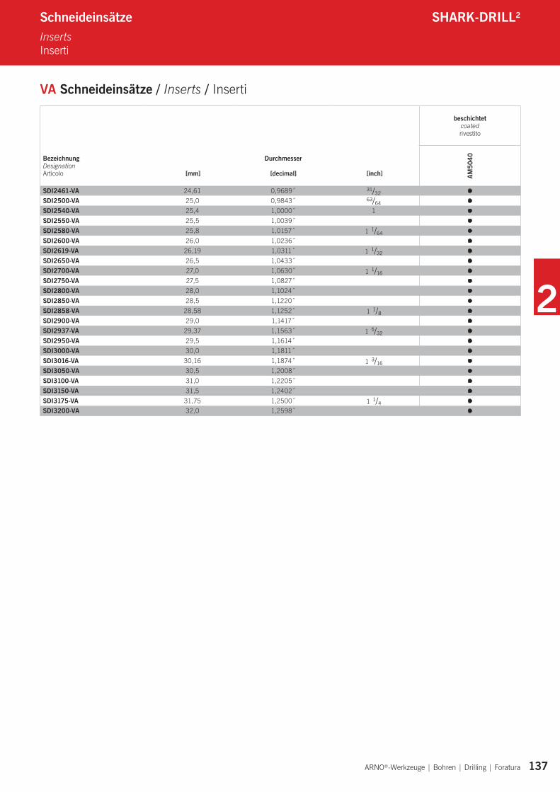
VA Schneideinsätze / Inserts / Inserti
beschichtet coated rivestito
BezeichnungDesignationArticolo
Durchmesser
[mm] [decimal] [inch] AM50
40
SDI2461-VA 24,61 0,9689˝ 31/32 l
SDI2500-VA 25,0 0,9843˝ 63/64 l
SDI2540-VA 25,4 1,0000˝ 1 l
SDI2550-VA 25,5 1,0039˝ l
SDI2580-VA 25,8 1,0157˝ 1 1/64 l
SDI2600-VA 26,0 1,0236˝ l
SDI2619-VA 26,19 1,0311˝ 1 1/32 l
SDI2650-VA 26,5 1,0433˝ l
SDI2700-VA 27,0 1,0630˝ 1 1/16 l
SDI2750-VA 27,5 1,0827˝ l
SDI2800-VA 28,0 1,1024˝ l
SDI2850-VA 28,5 1,1220˝ l
SDI2858-VA 28,58 1,1252˝ 1 1/8 l
SDI2900-VA 29,0 1,1417˝ l
SDI2937-VA 29,37 1,1563˝ 1 5/32 l
SDI2950-VA 29,5 1,1614˝ l
SDI3000-VA 30,0 1,1811˝ l
SDI3016-VA 30,16 1,1874˝ 1 3/16 l
SDI3050-VA 30,5 1,2008˝ l
SDI3100-VA 31,0 1,2205˝ l
SDI3150-VA 31,5 1,2402˝ l
SDI3175-VA 31,75 1,2500˝ 1 1/4 l
SDI3200-VA 32,0 1,2598˝ l
2
138 ARNO®-Werkzeuge | Bohren | Drilling | Foratura
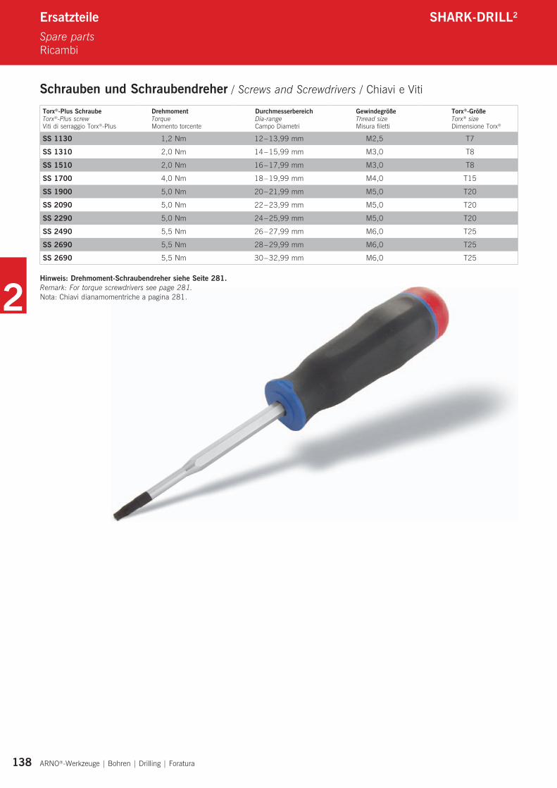
Torx®-Plus SchraubeTorx®-Plus screwViti di serraggio Torx®-Plus
DrehmomentTorqueMomento torcente
DurchmesserbereichDia-rangeCampo Diametri
GewindegrößeThread sizeMisura filetti
Torx®-GrößeTorx® sizeDimensione Torx®
SS 1130 1,2 Nm 12 – 13,99 mm M2,5 T7
SS 1310 2,0 Nm 14 – 15,99 mm M3,0 T8
SS 1510 2,0 Nm 16 – 17,99 mm M3,0 T8
SS 1700 4,0 Nm 18 – 19,99 mm M4,0 T15
SS 1900 5,0 Nm 20 – 21,99 mm M5,0 T20
SS 2090 5,0 Nm 22 – 23,99 mm M5,0 T20
SS 2290 5,0 Nm 24 – 25,99 mm M5,0 T20
SS 2490 5,5 Nm 26 – 27,99 mm M6,0 T25
SS 2690 5,5 Nm 28 – 29,99 mm M6,0 T25
SS 2690 5,5 Nm 30 – 32,99 mm M6,0 T25
Hinweis: Drehmoment-Schraubendreher siehe Seite 281.Remark: For torque screwdrivers see page 281.Nota: Chiavi dianamomentriche a pagina 281.
Ersatzteile SHARK-DRILL2
Spare partsRicambi
Schrauben und Schraubendreher / Screws and Screwdrivers / Chiavi e Viti
2
Alle Angaben in mm / Dimensions in mm / Tutte le dimensioni in mm ARNO®-Werkzeuge | Bohren | Drilling | Foratura 139
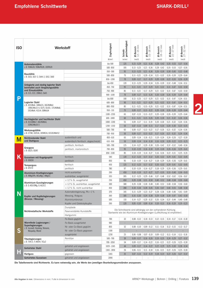
Die Tabellenwerte sind Richtwerte. Es kann notwendig sein, die Werte den jeweiligen Bearbeitungsumständen anzupassen.
ISO Werkstoff
Zugf
estig
keit
Schn
itt-
gesc
hwin
digk
eit
Ø-B
erei
ch
12 –
15 m
m
Ø-B
erei
ch
15 –
18 m
m
Ø-B
erei
ch
18 –
22 m
m
Ø-B
erei
ch
22 –
27 m
m
Ø-B
erei
ch
27 –
32 m
m
[N/mm2] [m/min] [mm/U] [mm/U] [mm/U] [mm/U] [mm/U]
P
Automatenstähle z. B. 9SMn28; 9SMnPb28; 10SPb20
bis 500 125 0,15 - 0,29 0,21 - 0,36 0,28 - 0,42 0,35 - 0,53 0,37 - 0,56
500 - 850 105 0,13 - 0,25 0,21 - 0,36 0,28 - 0,42 0,35 - 0,53 0,37 - 0,56
Baustähle z. B. St33; St37-2; St44-2; St52; St60
350 - 500 95 0,13 - 0,25 0,21 - 0,36 0,26 - 0,39 0,30 - 0,45 0,32 - 0,48
500 - 850 75 0,11 - 0,21 0,20 - 0,34 0,21 - 0,32 0,26 - 0,39 0,29 - 0,44
850 - 1200 70 0,09 - 0,17 0,17 - 0,29 0,20 - 0,30 0,22 - 0,33 0,26 - 0,39
Unlegierte und niedrig legierter Stahl beinhaltet auch Vergütungsstähle und Einsatzstählez. B. C15; C22; 20Mn5; Ck45
bis 450 120 0,13 - 0,25 0,20 - 0,34 0,26 - 0,39 0,32 - 0,48 0,34 - 0,51
450 - 750 95 0,11 - 0,21 0,17 - 0,29 0,21 - 0,32 0,31 - 0,47 0,33 - 0,50
750 - 900 85 0,11 - 0,21 0,17 - 0,29 0,21 - 0,32 0,31 - 0,47 0,33 - 0,50
900 - 1100 70 0,09 - 0,17 0,15 - 0,26 0,20 - 0,30 0,26 - 0,39 0,29 - 0,44
Legierter Stahlz. B. 42CrMo4; 16MnCr5; 36CrNiMo4
14NiCrMo13-4; Ck75; Ck101; 17CrNiMo8, 35CrMo4; 41Cr4; 50MnSi4
bis 600 100 0,13 - 0,25 0,17 - 0,29 0,21 - 0,32 0,31 - 0,47 0,34 - 0,51
600 - 800 90 0,11 - 0,21 0,17 - 0,29 0,21 - 0,32 0,31 - 0,47 0,34 - 0,51
800 - 950 85 0,11 - 0,21 0,15 - 0,26 0,21 - 0,32 0,31 - 0,47 0,34 - 0,51
950 - 110 75 0,09 - 0,17 0,13 - 0,22 0,20 - 0,30 0,26 - 0,39 0,29 - 0,44
1100 - 1250 65 0,07 - 0,13 0,13 - 0,22 0,20 - 0,30 0,26 - 0,39 0,29 - 0,44
Hochlegierter und hochfester Stahlz. B. 41CrAlMo7; 36CrNiMo4;
32NiCrMo14-5
600 - 1000 60 0,11 - 0,21 0,15 - 0,26 0,20 - 0,30 0,21 - 0,32 0,24 - 0,36
1000 - 1200 55 0,09 - 0,17 0,11 - 0,19 0,20 - 0,30 0,21 - 0,32 0,24 - 0,36
1200 - 1350 50 0,07 - 0,13 0,09 - 0,15 0,17 - 0,26 0,20 - 0,30 0,23 - 0,35
Werkzeugstählez. B. C75W; 102Cr6; 105WCr6; X153CrMoV12
500 - 700 65 0,09 - 0,17 0,13 - 0,22 0,17 - 0,26 0,21 - 0,32 0,24 - 0,36
700 - 950 50 0,09 - 0,17 0,13 - 0,22 0,17 - 0,26 0,21 - 0,32 0,24 - 0,36
M Nichtrostender Stahlund Stahlguss
austenitisch und 450 - 610 65 0,09 - 0,14 0,16 - 0,21 0,19 - 0,24 0,24 - 0,26 0,27 - 0,30
austenitisch / ferritisch, abgeschreckt 610 - 930 50 0,09 - 0,14 0,14 - 0,18 0,16 - 0,20 0,20 - 0,22 0,23 - 0,25
KGrauguss z. B. GG25; GG40
perlitisch, ferritisch 500 - 700 125 0,14 - 0,27 0,20 - 0,38 0,26 - 0,42 0,37 - 0,52 0,40 - 0,56
perlitisch, martensitisch 700 - 850 95 0,10 - 0,19 0,16 - 0,30 0,19 - 0,30 0,26 - 0,36 0,29 - 0,41
850 - 1100 85 0,10 - 0,19 0,14 - 0,27 0,16 - 0,26 0,22 - 0,31 0,25 - 0,35
Gusseisen mit Kugelgraphit z. B. GGG50
ferritisch 540 120 0,12 - 0,23 0,17 - 0,32 0,20 - 0,32 0,29 - 0,41 0,32 - 0,45
perlitisch 850 95 0,10 - 0,19 0,14 - 0,27 0,18 - 0,29 0,26 - 0,36 0,29 - 0,41
Temperguss z. B. GTS70
ferritisch 450 125 0,12 - 0,23 0,17 - 0,32 0,20 - 0,32 0,29 - 0,41 0,32 - 0,45
perlitisch 780 97 0,10 - 0,19 0,14 - 0,27 0,18 - 0,29 0,26 - 0,36 0,29 - 0,41
N
Aluminium-Knetlegierungen z. B. AlMgSiPb; AlCuMg1; AMgSi1
nicht aushärtbar 200 450 0,10 - 0,19 0,17 - 0,27 0,27 - 0,35 0,33 - 0,40 0,36 - 0,43
aushärtbar, ausgehärtet 335 305 0,12 - 0,23 0,29 - 0,46 0,37 - 0,48 0,52 - 0,62 0,56 - 0,67
Aluminium-Gusslegierungen z. B. G-AlSi10Mg; G-ALSi12
≤ 12 % Si, ausgehärtet 250 450 0,20 - 0,38 0,31 - 0,50 0,40 - 0,52 0,48 - 0,58 0,50 - 0,60
≤ 12 % Si, aushärtbar, ausgehärtet 300 380 0,20 - 0,38 0,30 - 0,48 0,40 - 0,52 0,48 - 0,58 0,50 - 0,60
≤ 12 % Si, nicht aushärtbar 450 280 0,18 - 0,34 0,28 - 0,45 0,36 - 0,47 0,46 - 0,55 0,48 - 0,58
Kupfer und Kupferlegierungen(Bronze / Messing)
Automatenlegierung, Pb >1 % 370 145 0,15 - 0,29 0,23 - 0,37 0,28 - 0,36 0,38 - 0,46 0,41 - 0,49
Messing, Rotguss 300 185 0,16 - 0,30 0,24 - 0,38 0,29 - 0,38 0,39 - 0,47 0,42 - 0,50
Aluminiumbronze 500 110 0,14 - 0,27 0,20 - 0,32 0,26 - 0,34 0,37 - 0,44 0,40 - 0,48
Kupfer und Elektrolytkupfer 200 120 0,05 - 0,10 0,09 - 0,14 0,10 - 0,13 0,16 - 0,19 0,19 - 0,23
Nichtmetallische WerkstoffeDuroplaste
Die Schnittwerte sind abhängig von der vorhandenen Kühlung. Startwerte wie bei Aluminium-Knetlegierungen (Luftkühlung ist empfohlen).Faserverstärkte Kunststoffe
Hartgummi
SWarmfeste Legierungen / Superlegierungen z. B. Inconell, Hasteloy, Nimonic,
Waspaloy, Monel
Fe-Basis geglüht 700 32 0,08 - 0,12 0,10 - 0,13 0,12 - 0,15 0,14 - 0,17 0,14 - 0,18
Fe-Basis ausgehärtet 980 – – – – – –
Ni- oder Co-Basis geglüht 850 32 0,08 - 0,10 0,09 - 0,12 0,11 - 0,14 0,12 - 0,15 0,12 - 0,17
Ni- oder Co-Basis gegossen 1100 – – – – – –
ausgehärtet 1230 25 0,06 - 0,08 0,07 - 0,10 0,09 - 0,12 0,11 - 0,14 0,11 - 0,16
Titanlegierungen z. B. Ti99,5; Ti Al6V4; TiCu2
Reintitan 500 - 700 39 0,09 - 0,17 0,16 - 0,26 0,19 - 0,25 0,24 - 0,29 0,27 - 0,32
700 - 1050 34 0,09 - 0,17 0,14 - 0,22 0,16 - 0,21 0,22 - 0,26 0,25 - 0,30
HGehärteter Stahl
gehärtet und angelassen 1020 - 1365 44 0,09 - 0,17 0,14 - 0,22 0,22 - 0,29 0,25 - 0,30 0,28 - 0,34
gehärtet und angelassen 1365 - 1850 26 0,06 - 0,11 0,11 - 0,18 0,16 - 0,21 0,22 - 0,26 0,25 - 0,30
Hartguss gegossen 1365 35 0,07 - 0,13 0,12 - 0,19 0,18 - 0,23 0,22 - 0,26 0,27 - 0,32
Gehärtetes Gusseisen gehärtet und angelassen 2090 – – – – – –
Empfohlene Schnittwerte SHARK-DRILL2
2
140 ARNO®-Werkzeuge | Bohren | Drilling | Foratura Alle Angaben in mm / Dimensions in mm / Tutte le dimensioni in mm
Schnittwerte SHARK-DRILL®
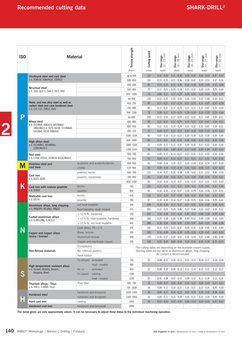
The datas given are only approximate values. It can be necessary to adjust these datas to the individual machining operation.
ISO Material
Tens
ile s
tren
gth
Cutti
ng s
peed
Dia
-ran
ge
12 –
15 m
m
Dia
-ran
ge
15 –
18 m
m
Dia
-ran
ge
18 –
22 m
m
Dia
-ran
ge
22 –
27 m
m
Dia
-ran
ge
27 –
32 m
m
[N/mm2] [m/min] [mm/U] [mm/U] [mm/U] [mm/U] [mm/U]
P
Unalloyed steel and cast steel e. G. 9SMn28; 9SMnPb28; 10SPb20
up to 500 125 0,15 - 0,29 0,21 - 0,36 0,28 - 0,42 0,35 - 0,53 0,37 - 0,56
500 - 850 105 0,13 - 0,25 0,21 - 0,36 0,28 - 0,42 0,35 - 0,53 0,37 - 0,56
Structual steel e. G. St33; St37-2; St44-2; St52; St60
350 - 500 95 0,13 - 0,25 0,21 - 0,36 0,26 - 0,39 0,30 - 0,45 0,32 - 0,48
500 - 850 75 0,11 - 0,21 0,20 - 0,34 0,21 - 0,32 0,26 - 0,39 0,29 - 0,44
850 - 1200 70 0,09 - 0,17 0,17 - 0,29 0,20 - 0,30 0,22 - 0,33 0,26 - 0,39
None- and low alloy steel as well as carbon steel and case hardened steel e. G. C15; C22; 20Mn5; Ck45
bis 450 120 0,13 - 0,25 0,20 - 0,34 0,26 - 0,39 0,32 - 0,48 0,34 - 0,51
450 - 750 95 0,11 - 0,21 0,17 - 0,29 0,21 - 0,32 0,31 - 0,47 0,33 - 0,50
750 - 900 85 0,11 - 0,21 0,17 - 0,29 0,21 - 0,32 0,31 - 0,47 0,33 - 0,50
900 - 1100 70 0,09 - 0,17 0,15 - 0,26 0,20 - 0,30 0,26 - 0,39 0,29 - 0,44
Alloys steele. G. 42CrMo4; 16MnCr5; 36CrNiMo4
14NiCrMo13-4; Ck75; Ck101; 17CrNiMo8, 35CrMo4; 41Cr4; 50MnSi4
bis 600 100 0,13 - 0,25 0,17 - 0,29 0,21 - 0,32 0,31 - 0,47 0,34 - 0,51
600 - 800 90 0,11 - 0,21 0,17 - 0,29 0,21 - 0,32 0,31 - 0,47 0,34 - 0,51
800 - 950 85 0,11 - 0,21 0,15 - 0,26 0,21 - 0,32 0,31 - 0,47 0,34 - 0,51
950 - 110 75 0,09 - 0,17 0,13 - 0,22 0,20 - 0,30 0,26 - 0,39 0,29 - 0,44
1100 - 1250 65 0,07 - 0,13 0,13 - 0,22 0,20 - 0,30 0,26 - 0,39 0,29 - 0,44
High alloys steele. G. 41CrAlMo7; 36CrNiMo4;
32NiCrMo14-5
600 - 1000 60 0,11 - 0,21 0,15 - 0,26 0,20 - 0,30 0,21 - 0,32 0,24 - 0,36
1000 - 1200 55 0,09 - 0,17 0,11 - 0,19 0,20 - 0,30 0,21 - 0,32 0,24 - 0,36
1200 - 1350 50 0,07 - 0,13 0,09 - 0,15 0,17 - 0,26 0,20 - 0,30 0,23 - 0,35
Tool steele. G. C75W; 102Cr6; 105WCr6; X153CrMoV12
500 - 700 65 0,09 - 0,17 0,13 - 0,22 0,17 - 0,26 0,21 - 0,32 0,24 - 0,36
700 - 950 50 0,09 - 0,17 0,13 - 0,22 0,17 - 0,26 0,21 - 0,32 0,24 - 0,36
M Stainless steel andcast steel
austenitic and austenitic/ferritic 450 - 610 65 0,09 - 0,14 0,16 - 0,21 0,19 - 0,24 0,24 - 0,26 0,27 - 0,30
chilled 610 - 930 50 0,09 - 0,14 0,14 - 0,18 0,16 - 0,20 0,20 - 0,22 0,23 - 0,25
KCast iron e. G. GG25; GG40
pearlitic, ferritic 500 - 700 125 0,14 - 0,27 0,20 - 0,38 0,26 - 0,42 0,37 - 0,52 0,40 - 0,56
pearlitic, martensitic 700 - 850 95 0,10 - 0,19 0,16 - 0,30 0,19 - 0,30 0,26 - 0,36 0,29 - 0,41
850 - 1100 85 0,10 - 0,19 0,14 - 0,27 0,16 - 0,26 0,22 - 0,31 0,25 - 0,35
Cast iron with nodular graphite e. G. GGG50
ferritic 540 120 0,12 - 0,23 0,17 - 0,32 0,20 - 0,32 0,29 - 0,41 0,32 - 0,45
pearlitic 850 95 0,10 - 0,19 0,14 - 0,27 0,18 - 0,29 0,26 - 0,36 0,29 - 0,41
Malleable cast iron e. G. GTS70
ferritic 450 125 0,12 - 0,23 0,17 - 0,32 0,20 - 0,32 0,29 - 0,41 0,32 - 0,45
pearlitic 780 97 0,10 - 0,19 0,14 - 0,27 0,18 - 0,29 0,26 - 0,36 0,29 - 0,41
N
Aluminium alloys, long chipping e. G. AlMgSiPb; AlCuMg1; AMgSi1
not heat treatable 200 450 0,10 - 0,19 0,17 - 0,27 0,27 - 0,35 0,33 - 0,40 0,36 - 0,43
heat treatable, heat - treated 335 305 0,12 - 0,23 0,29 - 0,46 0,37 - 0,48 0,52 - 0,62 0,56 - 0,67
Casted aluminium alloys e. G. G-AlSi10Mg; G-ALSi12
≤ 12 % Si, hardened 250 450 0,20 - 0,38 0,31 - 0,50 0,40 - 0,52 0,48 - 0,58 0,50 - 0,60
≤ 12 % Si, heat treatable, hardened 300 380 0,20 - 0,38 0,30 - 0,48 0,40 - 0,52 0,48 - 0,58 0,50 - 0,60
≤ 12 % Si, not heat treatable 450 280 0,18 - 0,34 0,28 - 0,45 0,36 - 0,47 0,46 - 0,55 0,48 - 0,58
Copper and copper alloys(brass / bronze)
Lead alloys, Pb >1 % 370 145 0,15 - 0,29 0,23 - 0,37 0,28 - 0,36 0,38 - 0,46 0,41 - 0,49
Brass, bronze 300 185 0,16 - 0,30 0,24 - 0,38 0,29 - 0,38 0,39 - 0,47 0,42 - 0,50
Aluminium bronze 500 110 0,14 - 0,27 0,20 - 0,32 0,26 - 0,34 0,37 - 0,44 0,40 - 0,48
Copper and electrolyte copper 200 120 0,05 - 0,10 0,09 - 0,14 0,10 - 0,13 0,16 - 0,19 0,19 - 0,23
Non-ferrous materialsDuroplastics The cutting datas are depending on the available coolant supply.
Starting datas are the same as aluminium alloys, long chipping. Air coolant is recommended.
Re- inforced plastics
Hard rubber
SHigh temperature resistant alloys e. G. Inconell, Hasteloy, Nimonic,
Waspaloy, Monel
Fe-alloyed annealed 700 32 0,08 - 0,12 0,10 - 0,13 0,12 - 0,15 0,14 - 0,17 0,14 - 0,18
heat - treated 980 – – – – – –
Ni- or annealed 850 32 0,08 - 0,10 0,09 - 0,12 0,11 - 0,14 0,12 - 0,15 0,12 - 0,17
Co based casting 1100 – – – – – –
heat - treated 1230 25 0,06 - 0,08 0,07 - 0,10 0,09 - 0,12 0,11 - 0,14 0,11 - 0,16
Titanium alloys / Titan e. G. Ti99,5; Ti Al6V4; TiCu2
Pure titan 500 - 700 39 0,09 - 0,17 0,16 - 0,26 0,19 - 0,25 0,24 - 0,29 0,27 - 0,32
700 - 1050 34 0,09 - 0,17 0,14 - 0,22 0,16 - 0,21 0,22 - 0,26 0,25 - 0,30
HHardened steel
hardened and tempered 1020 - 1365 44 0,09 - 0,17 0,14 - 0,22 0,22 - 0,29 0,25 - 0,30 0,28 - 0,34
hardened and tempered 1365 - 1850 26 0,06 - 0,11 0,11 - 0,18 0,16 - 0,21 0,22 - 0,26 0,25 - 0,30
Hard cast iron casting 1365 35 0,07 - 0,13 0,12 - 0,19 0,18 - 0,23 0,22 - 0,26 0,27 - 0,32
Hardened cast iron hardened and tempered 2090 – – – – – –
Recommended cutting data SHARK-DRILL2
2
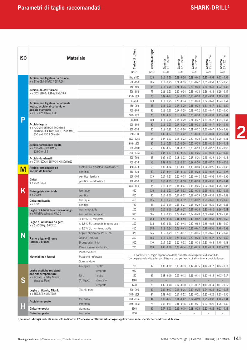
Alle Angaben in mm / Dimensions in mm / Tutte le dimensioni in mm ARNO®-Werkzeuge | Bohren | Drilling | Foratura 141
Schnittwerte SHARK-DRILL®
I parametri di tagli indicati sono solo indicativi. E’necessario ottimizzarli ad ogni applicazione sulle specifiche condizioni di lavoro.
ISO Materiale
Caric
o di
rottu
ra
Velo
cità
di t
aglio
Gam
ma
12 –
15 m
m
Gam
ma
15 –
18 m
m
Gam
ma
18 –
22 m
m
Gam
ma
22 –
27 m
m
Gam
ma
27 –
32 m
m
[N/mm2] [m/min] [mm/U] [mm/U] [mm/U] [mm/U] [mm/U]
P
Acciaio non legato o da fusione p. e. 9SMn28; 9SMnPb28; 10SPb20
fino a 500 125 0,15 - 0,29 0,21 - 0,36 0,28 - 0,42 0,35 - 0,53 0,37 - 0,56
500 - 850 105 0,13 - 0,25 0,21 - 0,36 0,28 - 0,42 0,35 - 0,53 0,37 - 0,56
Acciaio da costruzione p. e. St33; St37-2; St44-2; St52; St60
350 - 500 95 0,13 - 0,25 0,21 - 0,36 0,26 - 0,39 0,30 - 0,45 0,32 - 0,48
500 - 850 75 0,11 - 0,21 0,20 - 0,34 0,21 - 0,32 0,26 - 0,39 0,29 - 0,44
850 - 1200 70 0,09 - 0,17 0,17 - 0,29 0,20 - 0,30 0,22 - 0,33 0,26 - 0,39
Acciaio non legato o debolmente legato, acciaio al carbonio o acciaio stampatop. e. C15; C22; 20Mn5; Ck45
bis 450 120 0,13 - 0,25 0,20 - 0,34 0,26 - 0,39 0,32 - 0,48 0,34 - 0,51
450 - 750 95 0,11 - 0,21 0,17 - 0,29 0,21 - 0,32 0,31 - 0,47 0,33 - 0,50
750 - 900 85 0,11 - 0,21 0,17 - 0,29 0,21 - 0,32 0,31 - 0,47 0,33 - 0,50
900 - 1100 70 0,09 - 0,17 0,15 - 0,26 0,20 - 0,30 0,26 - 0,39 0,29 - 0,44
Acciaio legatop. e. 42CrMo4; 16MnCr5; 36CrNiMo4
14NiCrMo13-4; Ck75; Ck101; 17CrNiMo8, 35CrMo4; 41Cr4; 50MnSi4
bis 600 100 0,13 - 0,25 0,17 - 0,29 0,21 - 0,32 0,31 - 0,47 0,34 - 0,51
600 - 800 90 0,11 - 0,21 0,17 - 0,29 0,21 - 0,32 0,31 - 0,47 0,34 - 0,51
800 - 950 85 0,11 - 0,21 0,15 - 0,26 0,21 - 0,32 0,31 - 0,47 0,34 - 0,51
950 - 110 75 0,09 - 0,17 0,13 - 0,22 0,20 - 0,30 0,26 - 0,39 0,29 - 0,44
1100 - 1250 65 0,07 - 0,13 0,13 - 0,22 0,20 - 0,30 0,26 - 0,39 0,29 - 0,44
Acciaio fortemente legato p. e. 41CrAlMo7; 36CrNiMo4;
32NiCrMo14-5
600 - 1000 60 0,11 - 0,21 0,15 - 0,26 0,20 - 0,30 0,21 - 0,32 0,24 - 0,36
1000 - 1200 55 0,09 - 0,17 0,11 - 0,19 0,20 - 0,30 0,21 - 0,32 0,24 - 0,36
1200 - 1350 50 0,07 - 0,13 0,09 - 0,15 0,17 - 0,26 0,20 - 0,30 0,23 - 0,35
Acciaio da utensilip. e. C75W; 102Cr6; 105WCr6; X153CrMoV12
500 - 700 65 0,09 - 0,17 0,13 - 0,22 0,17 - 0,26 0,21 - 0,32 0,24 - 0,36
700 - 950 50 0,09 - 0,17 0,13 - 0,22 0,17 - 0,26 0,21 - 0,32 0,24 - 0,36
M Acciaio inossidabile ed acciaio da fusione
austenitico e austenitico / ferritico 450 - 610 65 0,09 - 0,14 0,16 - 0,21 0,19 - 0,24 0,24 - 0,26 0,27 - 0,30
temprato 610 - 930 50 0,09 - 0,14 0,14 - 0,18 0,16 - 0,20 0,20 - 0,22 0,23 - 0,25
KGhisa p. e. GG25; GG40
perlitica, ferritica 500 - 700 125 0,14 - 0,27 0,20 - 0,38 0,26 - 0,42 0,37 - 0,52 0,40 - 0,56
perlitica, martensitica 700 - 850 95 0,10 - 0,19 0,16 - 0,30 0,19 - 0,30 0,26 - 0,36 0,29 - 0,41
850 - 1100 85 0,10 - 0,19 0,14 - 0,27 0,16 - 0,26 0,22 - 0,31 0,25 - 0,35
Ghisa grigia sferoidale p. e. GGG50
ferritique 540 120 0,12 - 0,23 0,17 - 0,32 0,20 - 0,32 0,29 - 0,41 0,32 - 0,45
perlitica 850 95 0,10 - 0,19 0,14 - 0,27 0,18 - 0,29 0,26 - 0,36 0,29 - 0,41
Ghisa malleabile p. e. GTS70
ferritique 450 125 0,12 - 0,23 0,17 - 0,32 0,20 - 0,32 0,29 - 0,41 0,32 - 0,45
perlitica 780 97 0,10 - 0,19 0,14 - 0,27 0,18 - 0,29 0,26 - 0,36 0,29 - 0,41
N
Leghe di Alluminio a truciolo lungo p. e. AlMgSiPb; AlCuMg1; AMgSi1
non temprabile 200 450 0,10 - 0,19 0,17 - 0,27 0,27 - 0,35 0,33 - 0,40 0,36 - 0,43
temprabile, temprato 335 305 0,12 - 0,23 0,29 - 0,46 0,37 - 0,48 0,52 - 0,62 0,56 - 0,67
Leghe di Alluminio da getti p. e. G-AlSi10Mg; G-ALSi12
≤ 12 % Si, temprato 250 450 0,20 - 0,38 0,31 - 0,50 0,40 - 0,52 0,48 - 0,58 0,50 - 0,60
≤ 12 % Si, temprabile, temprato 300 380 0,20 - 0,38 0,30 - 0,48 0,40 - 0,52 0,48 - 0,58 0,50 - 0,60
≤ 12 % Si, non temprabile 450 280 0,18 - 0,34 0,28 - 0,45 0,36 - 0,47 0,46 - 0,55 0,48 - 0,58
Rame e leghe di rame (ottone / bronzo)
Legate al piombo, Pb >1 % 370 145 0,15 - 0,29 0,23 - 0,37 0,28 - 0,36 0,38 - 0,46 0,41 - 0,49
Ottone / Bronzo 300 185 0,16 - 0,30 0,24 - 0,38 0,29 - 0,38 0,39 - 0,47 0,42 - 0,50
Bronzo alluminio 500 110 0,14 - 0,27 0,20 - 0,32 0,26 - 0,34 0,37 - 0,44 0,40 - 0,48
Rame e rame elettrolitico 200 120 0,05 - 0,10 0,09 - 0,14 0,10 - 0,13 0,16 - 0,19 0,19 - 0,23
Materiali non ferrosiPlastiche dure
I parametri di taglio dipendono dalla quantità di refrigerante disponibile. Come parametri di partenza utilizzare dati per leghe di alluminio a truciolo lungo.Plastiche rinforzate
Gomme dure
SLeghe esotiche resistenti alle alte temperaturre p. e. Inconell, Hasteloy, Nimonic,
Waspaloy, Monel
Fe-legate ricotto 700 32 0,08 - 0,12 0,10 - 0,13 0,12 - 0,15 0,14 - 0,17 0,14 - 0,18
temprato 980 – – – – – –
Ni o ricotto 850 32 0,08 - 0,10 0,09 - 0,12 0,11 - 0,14 0,12 - 0,15 0,12 - 0,17
Co legato stampato 1100 – – – – – –
temprato 1230 25 0,06 - 0,08 0,07 - 0,10 0,09 - 0,12 0,11 - 0,14 0,11 - 0,16
Leghe di titanio, Titanio p. e. Ti99,5; Ti Al6V4; TiCu2
Titanio puro 500 - 700 39 0,09 - 0,17 0,16 - 0,26 0,19 - 0,25 0,24 - 0,29 0,27 - 0,32
700 - 1050 34 0,09 - 0,17 0,14 - 0,22 0,16 - 0,21 0,22 - 0,26 0,25 - 0,30
HAcciaio temprato
temprato 1020 - 1365 44 0,09 - 0,17 0,14 - 0,22 0,22 - 0,29 0,25 - 0,30 0,28 - 0,34
temprato 1365 - 1850 26 0,06 - 0,11 0,11 - 0,18 0,16 - 0,21 0,22 - 0,26 0,25 - 0,30
Ghisa temprata stampato 1365 35 0,07 - 0,13 0,12 - 0,19 0,18 - 0,23 0,22 - 0,26 0,27 - 0,32
Ghisa temprata temprato 2090 – – – – – –
Parametri di taglio raccomandati SHARK-DRILL2
2
142 ARNO®-Werkzeuge | Bohren | Drilling | Foratura
Neue Anwendung? Noch nie eingesetzt?• Wählen Sie den kürzest möglichen Halter
für die jeweilige Anwendung.• Auf Seite 139 in diesem Katalog erhalten
Sie detaillierte Empfehlungen zu Schnitt-werten. Dies sind Standardwerte für den allgemeinen Anwendungsfall. Die Maschi-nen- und Werkstückstabilität wurden hier-bei nicht berücksichtigt.
• Stellen Sie sicher, dass der Halter gut gespannt ist und einen maximalen Rund-lauffehler von 0,02 mm – 0,04 mm zum Zentrum hat.
Hierbei bitte auch auf die Montage der Platte achten (siehe Montage der Bohr-einsätze auf Seite 144).
• Prüfen Sie, ob der Kühlmitteldruck den Empfehlungen entspricht. Hohe Schnitt-werte erfordern einen angepassten Kühl-mitteldruck (siehe Seite 143)!
• Beim Anbohren auf einer ebenen Fläche kann mit vollem Vorschub angebohrt wer-den. Ein verbessertes Zentrierverhalten erreichen Sie, wenn der Vorschub beim Anbohren um 30 – 50 % reduziert wird.
• Bohren Sie nun ca. 1 bis 2 x D tief. Die Späne, die nach dem Anschnitt produziert werden, sollten kurz sein (nicht angelaufen oder blau).
• Stoppen Sie und messen Sie die Bohrung auf Toleranzhaltigkeit. Prüfen Sie auch das Zentrierverhalten und die Oberflächengüte.
• Wenn alles korrekt ist, führen Sie den Bohrvorgang weiter durch. Stellen Sie dabei sicher, dass der Bohrprozess stets ruhig und weichschneidend klingt.
New application? Never applied tool?• Select the shortest possible drill for the
application.• On page 140 of this catalogue leaflet you
can get cutting data recommendations. These are standard recommendations in general. Stability of machine and compo-nent is not taken into account.
• Please ensure that the holder is securely fastened and its run out is maximum 0.02 – 0.04 mm to centre.
Please also check insert assembly (see guidelines page 144).
• Please check that coolant pressure is as recommended. High cutting data needs suitable coolant pressure (see page 143).
• If drilling into a flat surface you can pre-drill using full feed rate. An improved centring is obtained, when pre-drilling, by reducing feed rate by 30 – 50 %.
• Drill 1 – 2 x D deep. The swarf should be short (not stringy or blue).
• Stop and measure the hole tolerance, check the straightness and surface finish.
• If all is correct, continue drilling. Ensuring that the drilling operation runs smooth and soft cutting.
Primo approccio alla punta? Prima prova?• Scegliereilcorpopuntapiùcortopossibile.• Apagina141diquestocatalogosono
indicati i parametri di taglio suggeriti per applicazioni generiche ed in ottimali condi-zioni di lavoro.
• Assicurarsichel’insertosiamontatosalda-mente (vedi pag 144) e correttamente con un run-out massimo di 0,02 – 0,04 mm e che lo stesso valore si ripresenti anche con il corpo punta montato sul mandrino.
• Assicurarsichelapressionedelrefrigerantesia sufficiente (vedi pag 143).
• Nelcasodiforatureinpianol’avanzamentopuò essere mantenuto costante ed al massimo die valori. In caso di necessità ridurre gli avanzamenti del 30 – 50 % per migliorare il centraggio.
• Comeprimafaseeseguireforidiprovapro-fondi 1 – 2 x D max e verificare la formazione del truciolo. Esso deve essere il più possibile corto e di colore chiaro.
Trucioli lunghi sono difficili da evacuare e trucioli blu indicano eccessivo calore.
• Verificareletolleranzediesecuzioneforoquali diametro, rotondità, linearità e rugosità superficiale.
• In caso di esito positivo proseguire la foratura prestando attenzione che i cicli mantengano un taglio dolce e continuo.
Anwendungshinweise SHARK-DRILL2
Application reference Applicazioni
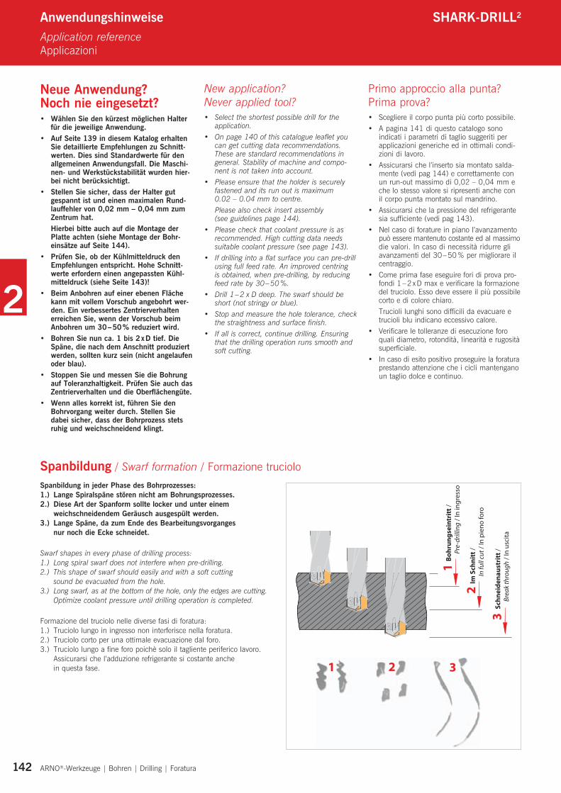
Spanbildung / Swarf formation / Formazione trucioloSpanbildung in jeder Phase des Bohrprozesses:1.) Lange Spiralspäne stören nicht am Bohrungsprozesses.2.) Diese Art der Spanform sollte locker und unter einem
weichschneidendem Geräusch ausgespült werden.3.) Lange Späne, da zum Ende des Bearbeitungsvorganges
nur noch die Ecke schneidet.
Swarf shapes in every phase of drilling process:1.) Long spiral swarf does not interfere when pre-drilling.2.) This shape of swarf should easily and with a soft cutting
sound be evacuated from the hole.3.) Long swarf, as at the bottom of the hole, only the edges are cutting.
Optimize coolant pressure until drilling operation is completed.
Formazione del truciolo nelle diverse fasi di foratura:1.) Truciolo lungo in ingresso non interferisce nella foratura.2.) Truciolo corto per una ottimale evacuazione dal foro.3.) Truciolo lungo a fine foro poichè solo il tagliente periferico lavoro.
Assicurarsi che l’adduzione refrigerante si costante anche in questa fase.
1
2
3
1 2 3
Bo
hru
ng
sein
trit
t /
Pre
-dril
ling
/ In
ingr
esso
Im S
chn
itt /
I
n fu
ll cu
t / In
pie
no fo
ro
Sch
nei
den
aust
ritt
/
Bre
ak th
roug
h / I
n us
cita
2
143 ARNO®-Werkzeuge | Bohren | Drilling | Foratura
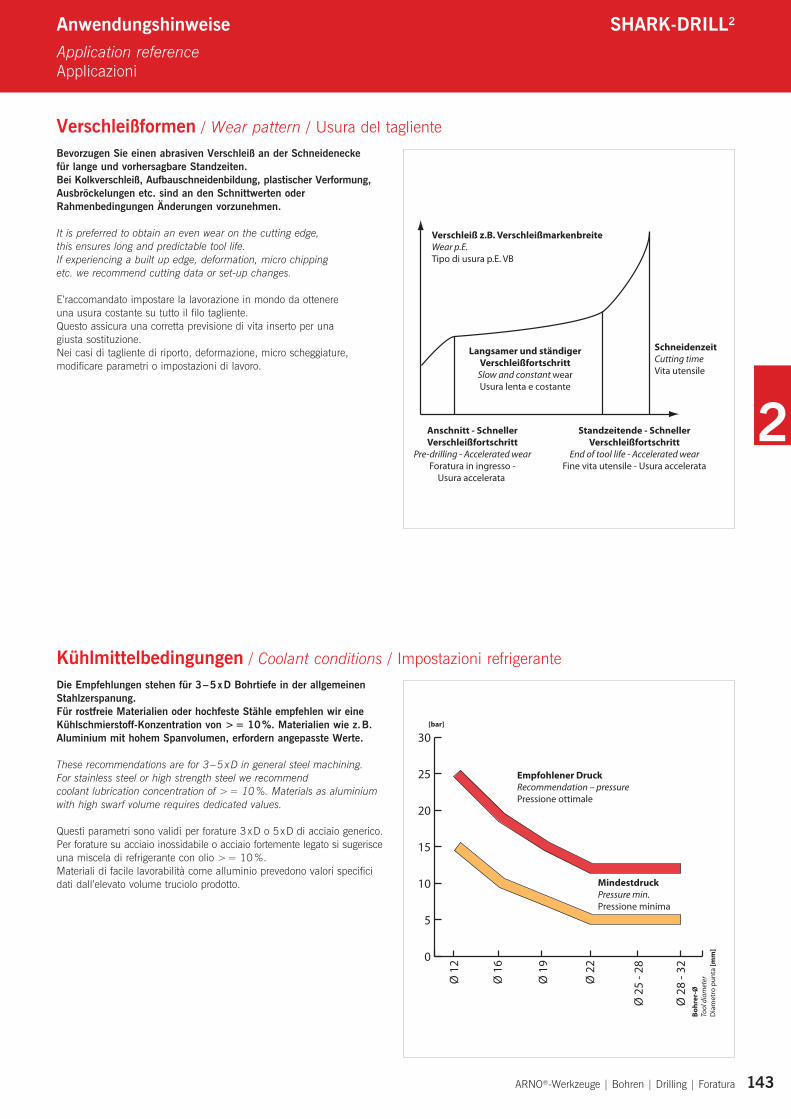
Bevorzugen Sie einen abrasiven Verschleiß an der Schneidenecke für lange und vorhersagbare Standzeiten.Bei Kolkverschleiß, Aufbauschneidenbildung, plastischer Verformung, Ausbröckelungen etc. sind an den Schnittwerten oderRahmenbedingungen Änderungen vorzunehmen.
It is preferred to obtain an even wear on the cutting edge, this ensures long and predictable tool life.If experiencing a built up edge, deformation, micro chipping etc. we recommend cutting data or set-up changes.
E’raccomandato impostare la lavorazione in mondo da ottenere una usura costante su tutto il filo tagliente.Questo assicura una corretta previsione di vita inserto per una giusta sostituzione.Nei casi di tagliente di riporto, deformazione, micro scheggiature, modificare parametri o impostazioni di lavoro.
Anwendungshinweise SHARK-DRILL2
Application reference Applicazioni
Verschleißformen / Wear pattern / Usura del tagliente
Kühlmittelbedingungen / Coolant conditions / Impostazioni refrigerante
Verschleiß z.B. VerschleißmarkenbreiteWear p.E.Tipo di usura p.E. VB
Anschnitt - SchnellerVerschleißfortschritt
Pre-drilling - Accelerated wearForatura in ingresso -
Usura accelerata
Standzeitende - SchnellerVerschleißfortschritt
End of tool life - Accelerated wearFine vita utensile - Usura accelerata
Langsamer und ständigerVerschleißfortschritt
Slow and constant wearUsura lenta e costante
SchneidenzeitCutting timeVita utensile
Die Empfehlungen stehen für 3 – 5 x D Bohrtiefe in der allgemeinen Stahlzerspanung.Für rostfreie Materialien oder hochfeste Stähle empfehlen wir eine Kühlschmierstoff-Konzentration von > = 10 %. Materialien wie z. B. Aluminium mit hohem Spanvolumen, erfordern angepasste Werte.
These recommendations are for 3 – 5 x D in general steel machining. For stainless steel or high strength steel we recommendcoolant lubrication concentration of > = 10 %. Materials as aluminium with high swarf volume requires dedicated values.
Questi parametri sono validi per forature 3 x D o 5 x D di acciaio generico.Per forature su acciaio inossidabile o acciaio fortemente legato si sugerisce una miscela di refrigerante con olio > = 10 %.Materiali di facile lavorabilità come alluminio prevedono valori specifici dati dall’elevato volume truciolo prodotto.
0
5
10
15
20
25
30
Empfohlener DruckRecommendation – pressurePressione ottimale
[bar]
Bo
hre
r-Ø
Tool
dia
met
erD
iam
etro
pun
ta [m
m]
Ø 1
2
Ø 1
6
Ø 1
9
Ø 2
2
Ø 2
5 - 2
8
Ø 2
8 - 3
2
MindestdruckPressure min.Pressione minima
2
144 ARNO®-Werkzeuge | Bohren | Drilling | Foratura Alle Angaben in mm / Dimensions in mm / Tutte le dimensioni in mm
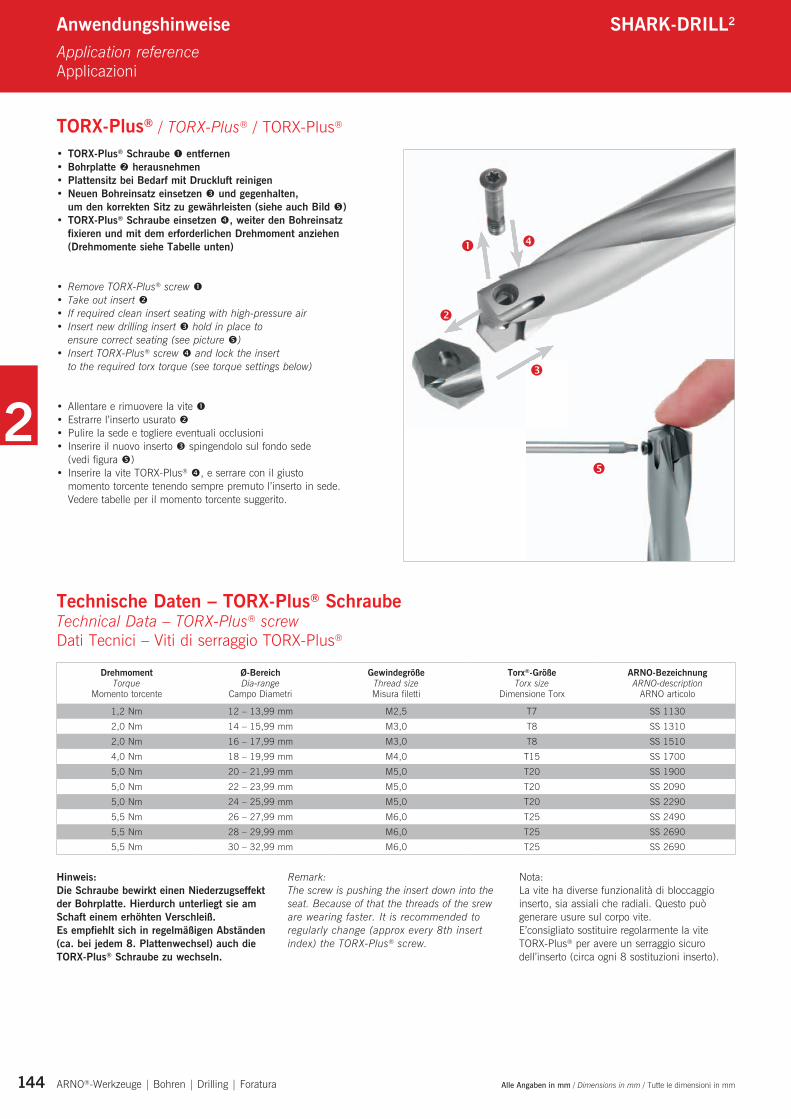
• TORX-Plus® Schraube entfernen• Bohrplatte herausnehmen• Plattensitz bei Bedarf mit Druckluft reinigen• Neuen Bohreinsatz einsetzen und gegenhalten,
um den korrekten Sitz zu gewährleisten (siehe auch Bild )• TORX-Plus® Schraube einsetzen , weiter den Bohreinsatz
fixieren und mit dem erforderlichen Drehmoment anziehen (Drehmomente siehe Tabelle unten)
• Remove TORX-Plus® screw • Take out insert • If required clean insert seating with high-pressure air • Insert new drilling insert hold in place to
ensure correct seating (see picture )• Insert TORX-Plus® screw and lock the insert
to the required torx torque (see torque settings below)
• Allentareerimuoverelavite• Estrarrel’insertousurato• Pulirelasedeetogliereeventualiocclusioni• Inserireilnuovoinserto spingendolo sul fondo sede
(vedi figura )• InserirelaviteTORX-Plus® , e serrare con il giusto
momento torcente tenendo sempre premuto l’inserto in sede. Vedere tabelle per il momento torcente suggerito.
Anwendungshinweise SHARK-DRILL2
Application reference Applicazioni
TORX-Plus® / TORX-Plus® / TORX-Plus®
Technische Daten – TORX-Plus® Schraube Technical Data – TORX-Plus® screw Dati Tecnici – Viti di serraggio TORX-Plus®
DrehmomentTorque
Momento torcente
Ø-BereichDia-range
Campo Diametri
Gewindegröße Thread sizeMisura filetti
Torx®-GrößeTorx size
Dimensione Torx
ARNO-BezeichnungARNO-description
ARNO articolo
1,2 Nm 12 – 13,99 mm M2,5 T7 SS 1130
2,0 Nm 14 – 15,99 mm M3,0 T8 SS 1310
2,0 Nm 16 – 17,99 mm M3,0 T8 SS 1510
4,0 Nm 18 – 19,99 mm M4,0 T15 SS 1700
5,0 Nm 20 – 21,99 mm M5,0 T20 SS 1900
5,0 Nm 22 – 23,99 mm M5,0 T20 SS 2090
5,0 Nm 24 – 25,99 mm M5,0 T20 SS 2290
5,5 Nm 26 – 27,99 mm M6,0 T25 SS 2490
5,5 Nm 28 – 29,99 mm M6,0 T25 SS 26905,5 Nm 30 – 32,99 mm M6,0 T25 SS 2690
Hinweis:Die Schraube bewirkt einen Niederzugseffekt der Bohrplatte. Hierdurch unterliegt sie am Schaft einem erhöhten Verschleiß.Es empfiehlt sich in regelmäßigen Abständen (ca. bei jedem 8. Plattenwechsel) auch die TORX-Plus® Schraube zu wechseln.
Remark:The screw is pushing the insert down into the seat. Because of that the threads of the srew are wearing faster. It is recommended to regularly change (approx every 8th insert index) the TORX-Plus® screw.
Nota:La vite ha diverse funzionalità di bloccaggio inserto, sia assiali che radiali. Questo può generare usure sul corpo vite.E’consigliato sostituire regolarmente la vite TORX-Plus® per avere un serraggio sicuro dell’inserto (circa ogni 8 sostituzioni inserto).
2
145 ARNO®-Werkzeuge | Bohren | Drilling | Foratura
Anwendungshinweise SHARK-DRILL2
Application reference Applicazioni
Formeln / Formulas / Formule
MC Drehmoment [Nm] Torque Coppia (Momento torcente)
KC Spezifische Schnittkraft [N/mm²] Chip thickness Coefficiente di taglio
f Vorschub [mm/U] Feed rate Avanzamento
d² Durchmesser 2 [mm] Diameter 2 Diametro
PC Schnittleistung [kW] Cutting rate Assorbimento potenza
d Durchmesser [mm] Diameter Diametro di foratura
VC Schnittgeschwindigkeit [m/min] Cutting speed Velocità di taglio
n Drehzahl [U/min] Revolution per minute Velocità di rotazione
Vf Vorschubgeschwindigkeit [mm/min] Feed rate Velocità di avanzamento
FA Axiale Vorschubkraft [N] Axial feed rate power Assorbimento potenza in spinta
K Faktor für spezifische Schnittkraft beim Bohren
Value for specific cutting force Coefficiente di taglio specifico
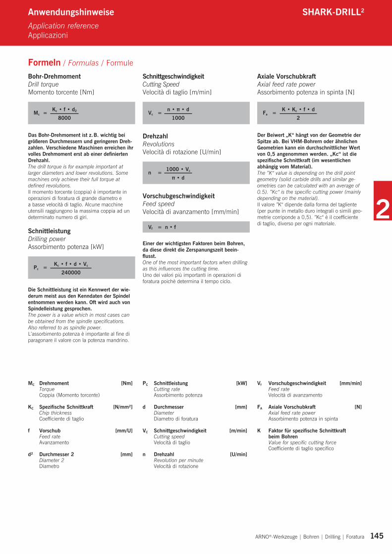
Bohr-Drehmoment Drill torque Momento torcente [Nm]
Mc = Kc • f • d2
8000
Das Bohr-Drehmoment ist z. B. wichtig bei größeren Durchmessern und geringeren Dreh-zahlen. Verschiedene Maschinen erreichen ihr volles Drehmoment erst ab einer defi nierten Drehzahl. The drill torque is for example important at larger diameters and lower revolutions. Some machines only achieve their full torque at defi ned revolutions.Il momento torcente (coppia) è importante in operazioni di foratura di grande diametro e a basse velocità di taglio. Alcune macchine utensili raggiungono la massima coppia ad un determinato numero di giri.
Schnittleistung Drilling power Assorbimento potenza [kW]
Pc = Kc • f • d • Vc
240000
Die Schnittleistung ist ein Kennwert der wie-derum meist aus den Kenndaten der Spindel entnommen werden kann. Oft wird auch von Spindelleistung gesprochen.The power is a value which in most cases can be obtained from the spindle specifi cations. Also referred to as spindle power.L’assorbimento potenza è importante al fi ne di paragonare il valore con la potenza mandrino.
SchnittgeschwindigkeitCutting Speed Velocità di taglio [m/min]
Vc = n • π • d1000
Drehzahl Revolutions Velocità di rotazione [U/min]
n = 1000 • Vc
π • d
Vorschubgeschwindigkeit Feed speed Velocità di avanzamento [mm/min]
Vf = n • f
Einer der wichtigsten Faktoren beim Bohren, da diese direkt die Zerspanungszeit beein-fl usst.One of the most important factors when drilling as this infl uences the cutting time.Uno dei valori più importanti in operazioni di foratura poichè determina il tempo ciclo.
Axiale VorschubkraftAxial feed rate powerAssorbimento potenza in spinta [N]
Fa = K • Kc • f • d2
Der Beiwert „K“ hängt von der Geometrie der Spitze ab. Bei VHM-Bohrern oder ähnlichen Geometrien kann ein durchschnittlicher Wert von 0,5 angenommen werden. „Kc“ ist die spezifi sche Schnittkraft (im wesentlichen abhängig vom Material).The ”K“ value is depending on the drill point geometry (solid carbide drills and similar ge-ometries can be calculated with an average of 0.5). ”Kc“ is the specifi c cutting power (mainly depending on the material).Il valore ”K“ dipende dalla forma del tagliente (per punte in metallo duro integrali o simili geo-metrie corriponde a 0,5). ”Kc“ è il coeffi ciente di taglio, diverso per ogni materiale.
• Wir bieten Ihnen Sonderlösungen für Ihre
individuellen Bedürfnisse.
• Bestellen Sie bis 18 Uhr unsere Produkte,
erhalten Sie Ihre Lieferung bereits am
nächsten Tag.
• Da wir Konstruktion, Produktion und Vertrieb
unter einem Dach vereinen, können wir eine
hohe Qualität unserer Produkte garantieren.
• Die Mitarbeiter unseres Außendienstes
besuchen Sie regelmäßig und unterstützen
Sie mit ihrem Produktwissen.
• Unsere Anwendungstechniker beraten
Sie direkt vor Ort in Ihrem Werk.
• Die kompetenten ARNO-Ansprechpartner
stehen Ihnen bei Fragen und Anliegen gerne
zur Verfügung – weltweit.
• We offer special solutions for your individual
requirement.
• Order your products by 15.30 CET for same
day dispatch.
• As we design, manufacture, and service our
own products, we offer you only top quality
products.
• Our external sales engineers will be visiting
regularly.
• Our trained engineers are experienced and will
be able to help you with most applications.
• Our competent global ARNO-partners are
always available to answer any questions you
may have.
•Offriamo soluzioni speciali per le vostre
esigenze.
•Ordinate i nostri prodotti entro le 15,30 e li
avrete il giorno dopo.
•Possiamo offrivi la massima qualità avendo
priduzione, progettazione e vendita in un unico
posto.
•Verete visitati regolarmente dai nostri
collaboratori.
•I nostri tecnici sapranno consigliarvi per il
meglio.
•Tutto il team ARNO è a vostra completa
disposizione.
Schnell, fl exibel und individuell.Quick, fl exible and individual.Veloce, fl essibile e individuale.
ARNO-SERVICE
Weitere Informationen fi nden Sie unter For more information see
Altre informazioni sotto
Uhr. GEBÜHRENFREI. www.arno.de


![Shark FX/LT 8.0 : Produkt-Information - POSH GmbHposh.de/download/sfx/Shark FX-LT 8.0-DE.pdfShark Funktionen Shark FX / Shark LT [Auszug] Benutzerfreundlich Legen klassische Maschinenbau-CAD-Systeme](https://img.pdfslide.tips/doc/110x75/5e5a4a8f3a94ee365b10ba72/shark-fxlt-80-produkt-information-posh-fx-lt-80-depdf-shark-funktionen-shark.jpg)