Embed Size (px)
Citation preview
8/10/2019 Shimizu Aerial Shell Ballistic Predictions
http://slidepdf.com/reader/full/shimizu-aerial-shell-ballistic-predictions 1/12
Page 138 Selected Pyrotechnic Publications of K.L. and B.J. Kosanke
Originally appeared in Pyrotechnics Guild International Bulletin , Nos. 72 and 73 (1990).
Shimizu Aerial Shell Ballistic Predictions (Part 1)
by K.L. and B.J. Kosanke
Introduction
The effect of varying aerial shell and mortar parameters is a frequent topic of discussion in thedisplay fireworks industry. Dr. Takeo Shimizu has
published equations describing both internal(within the mortar) and external (after leaving themortar) aerial shell ballistics 1. These equationscan be used to make general predictions of theeffects of aerial shell and mortar characteristics onshell and mortar performance. Shimizu's work
only addressed spherical shells; however, hisequations can be used for cylindrical shells
providing an appropriate drag coefficient is used.(For the purposes of this article, the drag coeffi-cient of air resistance for cylindrical shells wasassumed to be twice the value used by Shimizufor spherical shells.)
In this article, the authors have used the Shimi-zu equations in order to determine the relativeeffects of varying aerial shell and mortar charac-teristics. In the belief that the results generallyspeak for themselves, the reader is usually left todraw their own conclusions and supply their ownrationales. Occasionally, however, this article pre-sents some conclusions or discusses the reasonsfor the results.
Before presenting the results of this study, twosubjects must be presented. The first is a generaldiscussion of the reliability of predictions basedon mathematical models (equations). The secondis an enumeration of nominal aerial shell and mor-tar input values used in this study.
Reliability of Predictions Using Math-ematical Models
The reliability of predictions made usingmathematical models (equations) is almost always
limited because simplifications and assumptionsusually have been made in their derivation. Insome cases, simplifications are made in order tomake it possible to perform the calculations; inother cases the simplifications just make it easieror faster to perform the calculations.
As an example of one type of simplificationthat is required in the case of aerial shell ballistics,consider the following. The microscopic airflowaround an aerial shell first being propelled withina mortar and then moving through the air, is sovery complex that even the best aerodynamic en-gineers, using the most sophisticated computers,cannot perform the necessary calculations. In thiscase, there is no choice except to simplify the cal-culations by only considering average (macro-scopic) effects of airflow. When this is done, it isappropriate to ask whether this limits the accuracyof the calculated results. Of course, the answer isyes; but the errors are not great, and remember,the choice was to simplify the problem or to not
perform the calculations at all.
Simplifying assumptions always introducesome error, at least under some circumstances.Thus it is important to consider when such simpli-fications are appropriate. One such case is whenthere are uncertainties in input parameters, such asthe exact weight, diameter, or amount of lift for atypical shell. Those uncertainties in input parame-ters cause uncertainties in the results. When thoseuncertainties in the results are significantly greaterthan the errors introduced by the simplifying as-sumptions, the simplifications are appropriate.Another case, when simplifications are appropri-
ate, is when it is only desired to draw general con-clusions from the results, and the accuracy of eachindividual calculated result is of lesser im-
portance. In the present study of aerial shell ballis-tics, both cases are applicable, and Shimizu's sim-
plifying assumptions are appropriate.
8/10/2019 Shimizu Aerial Shell Ballistic Predictions
http://slidepdf.com/reader/full/shimizu-aerial-shell-ballistic-predictions 2/12
Selected Pyrotechnic Publications of K.L. and B.J. Kosanke Page 139
When considering errors introduced by simpli-fications, there is one more thing that must be ad-dressed. The magnitude of those errors generally
depends on how greatly conditions differ betweenthose being calculated and those assumed by thesimplification. In effect this introduces limits onwhen these errors can be safely ignored. As anexample of this consider the following. One result
predicted by the Shimizu equations is the locationof an aerial shell inside a mortar when it will besubjected to the greatest lift pressure. Generally anaerial shell will be 7 to 11 inches above the bot-tom of the mortar when maximum pressure isreached. As an example of the limits that are im-
posed by simplifying assumptions, consider the
very extreme case of a mortar that is only five-inches tall. In this case, the Shimizu equations still predict that the maximum pressure will occurwhen the shell has risen 7 to 11 inches in the mor-tar. Obviously this is impossible! The lesson hereis that, while the Shimizu equations may workquite well when using values only a little differentfrom normal, as more and more extreme valuesare used, one must be more and more cautions inaccepting the results.
Within the purpose of this paper, which is onlyto draw some very general conclusions about in-ternal and external aerial shell ballistics, the au-
thors feel that the errors introduced because ofsimplifying assumptions are within acceptablelimits. However, the reader must be cautioned thatno experimental data was collected by the authorsfor the purpose of verifying the results using theShimizu equations. Thus, it is not possible toquantify the magnitude of the errors in the resultsreported here.
Nominal Shell and Mortar Input Values
Table 1 lists the nominal values for input pa-
rameters used in this paper. For spherical shells,many of the values were taken from Shimizu 1 byinterpolation to US shell sizes. Other values werederived using a combination of measurements ofactual shells and mortars, and recommendationsof various fireworks experts. Unless otherwisespecified, the results reported in this paper usethose nominal values as input parameters for thecalculations.
Table 1. Nominal Shell and Mortar Parameters.
Shell Lift Dead MortarShell Shell Diameter Weight Powder Weight Volume LengthType Size (inches)
(a) (pounds)
(a) Type
(c) (ounces)
(a) (cubic in.) (inches)
S p
h e r i c
a l 3 2.75 0.3 2-3Fg 0.5 12 24
4 3.70 0.8 2-3Fg 1.0 24 24
5 4.60 1.5 2-3Fg 1.7 46 306 5.55 2.5 2-3Fg 2.7 72 368 7.50
(b) 5.5 2-3Fg 5.5 150 42
10 9.50 11. 2-3Fg 10 290 4812 11.50
(b) 18. 2-3Fg 17 520 48
C y
l i n d r i c a
l 3 2.75 0.4 2FA 1.0 9 244 3.7 1.0 2FA 1.9 20 245 4.7 2.0 2FA 3.0 35 306 5.7 4.0 2FA 4.5 57 368 7.6 10. 2FA 9.0 121 42
10 9.5 20. 2FA 16 234 4812 11.5 36. 2FA 26 394 48
Notes:
a) Values for spherical shells were derived by interpolating values reported by Shimizu1 p.183.
b) Values derived from Shimizu were 0.05 to 0.1 inches smaller, but it was decided to follow the NFPA guide-line that the gap between shell and mortar not exceed 0.5 inches.
c) See Table 3, this suggests that 2Fg powder is the US grade most nearly like the Type 0 lift powder used byShimizu.
8/10/2019 Shimizu Aerial Shell Ballistic Predictions
http://slidepdf.com/reader/full/shimizu-aerial-shell-ballistic-predictions 3/12
Page 140 Selected Pyrotechnic Publications of K.L. and B.J. Kosanke
The Black Powder granulations used in Japandiffer from those used in the United States. Table2 compares Japanese and US granulations. Shimi-zu reports "characteristic values" for JapaneseBlack Powder granulations, and these are used asinput parameters in his equations. In order tomake this paper of greater value to users of USBlack Powder granulations, it was necessary todesignate which US granulations correspond toShimizu's characteristic values. These assign-
ments are shown in Table 3.
Table 3. Characteristic Values for Lift Powders
Corresponding Characteristic Valuesa
Japanese American Af AG f/G
Powder type Powder type (dm /kg · sec) (dm /kg · sec) (dm)
0 2-3Fg 17200 0.256 671001 4Fg 17500 0.356 491002 2Fg 16000 0.213 751003 Fg or 3-4FA 13200 0.182 725004 2FA 10900 0.128 85200
Notes:
a) Characteristic values were taken from Shimizu (1), Table 33, p. 170, where A is Charbonnier's "vivacity" ofthe lift powder in dm 2/kg · sec, f is the explosive force of the lift powder in kg · dm/kg, and G is the grain shapefunctions of the lift powder which is dimensionless. (Note dm is decimeter = 10 cm, and kg is kilogram = 1000grams.)
b) From Table 2, these are the American powder types with mesh range most nearly duplicating thosereported by Shimizu.
Table 2. Comparison between Japanese and American Black Powder Mesh Sizes.
Japanese Mesh American MeshPowder type
a Range (inches) Powder type Range (inches)
c
0 0.016–0.047 4Fg 0.006–0.0161 0.008–0.016 3Fg 0.012–0.0332 0.016–0.047 2Fg 0.023–0.047
3 0.047–0.067 4FA 0.033–0.0664 0.094–0.134 Fg 0.047–0.066
3FA 0.047–0.0792FA 0.066–0.187
Notes:
a) As defined by Shimizu 1, Table 33, p. 170.
b) Values were converted to sieve openings in inches. See Shimizu 1, Table 33, p. 170 for percent pass-ing and retained on sieves.
c) Values derived from information contained in Engineering Design Handbook (AMCP 106-175) -Explosives Series - Solid Propellants Part One - The percent passing fine mesh sieve is 3%, and theretained on coarse mesh sieve is 12%.
8/10/2019 Shimizu Aerial Shell Ballistic Predictions
http://slidepdf.com/reader/full/shimizu-aerial-shell-ballistic-predictions 4/12
8/10/2019 Shimizu Aerial Shell Ballistic Predictions
http://slidepdf.com/reader/full/shimizu-aerial-shell-ballistic-predictions 5/12
Page 142 Selected Pyrotechnic Publications of K.L. and B.J. Kosanke
• Maximum mortar pressures are reached be-fore the shells rise very far above the bottomof the mortar.
• Rise times for shells are shorter than fall
times.Readers are again cautioned to consider these
shell performance values only within the contextof this paper. These values are calculated results
based on numerous assumptions and only for thenominal input values assumed. These performancevalues are not the results of actual measurementsand they may be only approximately correct.
Effects of Mortar Length
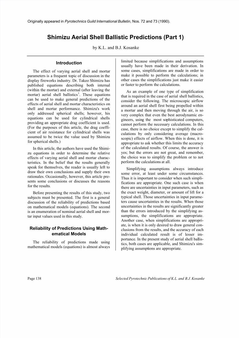
Over the years, there has probably been morespeculation regarding the effect of mortar lengthon the flight of aerial shells than any other singlefactor. The results of calculations of maximumshell height for 3, 6, and 12-inch shells as a func-tion of mortar length are listed in Table 5. Maxi-mum shell heights are listed both in absoluteterms and as a percent of the heights achievedwhen using mortar lengths 20 times the diameter.These same data are presented in Figure 4. Forconvenience in plotting, mortar lengths are ex-
pressed as multiples of mortar internal diameters.
It may be of interest to examine the data in or-
der to evaluate the appropriateness of the rule-of-thumb recommending use of mortars 5-times theirID for shells less than 8-inches and 4-times theirID for shells 8-inches or more. For small shells, itseems there might be an advantage in using mor-tars that were somewhat longer. However, giventhe burst radii of hard breaking shells 3, it does notseem that the 5-times diameter rule represents asafety concern.
It might also be of interest to comment on therelationship between a shell's muzzle velocity andthe maximum height it attains. In order to do this,consider the muzzle velocity and maximum height
data for three-inch spherical shells, listed in Table6 and shown in Figure 5. With increasing mortarlength, muzzle velocity and maximum height bothincrease; however, the increase in maximumheight is not as great as the increase in muzzlevelocity. The reason for this difference is that aer-odynamic drag is a function of a shell's velocity 1,4.The faster a shell is moving, the greater are thelosses due to drag forces. Thus increases in muz-zle velocity cause greater drag forces, which inturn allow less than proportional increases in shellheight.
0
20
40
60
80
100
% IncreasedValue
0 10 20 30 40 50 60 70Mortar Length (inches)
Muzzle VelocityMaximum Height
Figure 5. Comparison of increases in maximum shell height and muzzle velocity as a function ofmortar length for three-inch spherical shells.
End of Part 1 : (The remainder of this articlewill continue to address the effects of altering in-
put values; for example varying mortar to shellclearance, shell weights, and loading spaces.)
3.54.0
4.5
5.0
5.5
6.0
6.5
7.0
Timeto Max.Altitude(seconds)
0 2 4 6 8 10 12Nominal Shell Size (inches)
CylindricalSpherical
Figure 3. Time taken to reach maximum shellheight as a function of shell size for nominalinput parameters.
300
400
500
600
700
800
900
1000
ShellHeight(feet)
0 4 8 12 16 20 24Mortar Length / Diameter (inches)
12" Cylindrical
12" Spherical
6" Spherical6" Cylindrical
3" Spherical
3" Cylindrical
Figure 4. Maximum shell height as a function ofmortar length.
8/10/2019 Shimizu Aerial Shell Ballistic Predictions
http://slidepdf.com/reader/full/shimizu-aerial-shell-ballistic-predictions 6/12
Selected Pyrotechnic Publications of K.L. and B.J. Kosanke Page 143
References for Part 1
1) Shimizu, T., 1985. Fireworks from a PhysicalStandpoint Part III , Pyrotechnica Publica-tions, Austin, TX.
2) Kosanke, K.L., Schwertly, L.A., and Kosan-ke, B.J., "Report of Aerial Shell Burst HeightMeasurements", PGI Bulletin , No. 68 (1990).
3) Kosanke, K.L. and B.J., "Japanese ShellBreak Radii", PGI Bulletin , No. 59 (1988).
4) Kosanke, K.L. and B.J., "Computer Modelingof Aerial Shell Ballistics,” Pyrotechnica XIV (1992).
Table 5. Effect of Mortar Length on Maximum Shell Height.
Mortar Length 3" Shell 6" Shell 12" ShellDivided by Height Percent Height Percent Height PercentDiameter (feet) (a) (feet) (a) (feet) (a)
S p
h e r i c a
l3 336 62 645 72 860 874 384 70 701 78 898 91
5 415 76 733 82 920 936 438 80 765 86 934 958 470 86 804 90 951 97
12 507 93 848 95 969 9816 528 97 874 98 979 9920 545 100 893 100 984 100
C
y l i n d r i c a
l 3 369 74 660 78 900 904 398 80 702 83 929 935 418 84 731 87 946 956 432 86 751 89 957 968 452 90 779 92 971 97
12 476 95 812 96 986 99
16 489 98 831 98 993 9920 500 100 845 100 998 100
(a) Height expressed as the percent of the height reached when mortar length is 20 times the mortar di-ameter.
Table 6. Effect of Mortar Length on Maximum Shell Height and Muzzle Velocity for Three-InchSpherical Shells.
Mortar Length(inches)
Muzzle Velocity(ft/sec)
Percent In-creased
Velocity (a)
Maximum Height(feet)
Percent In-creased
Shell Height (a)
9 242 0 336 012 279 15 383 1415 307 27 415 2418 327 35 438 3024 358 48 470 4036 398 64 507 5148 425 76 529 5760 444 83 545 62
(a) Muzzle velocity and height as the percent increase to that for a nine-inch long mortar.
8/10/2019 Shimizu Aerial Shell Ballistic Predictions
http://slidepdf.com/reader/full/shimizu-aerial-shell-ballistic-predictions 7/12
Page 144 Selected Pyrotechnic Publications of K.L. and B.J. Kosanke
Originally appeared in Pyrotechnics Guild International Bulletin , No. 73 (1990).
Shimizu Aerial Shell Ballistic Predictions (Part 2)
by K.L. and B.J. Kosanke(Continuation of Part 1, which appeared in Pyrotechnics Guild International Bulletin No. 72 (1990).
Effects of Shell Clearance in Mortar
Another area of frequent speculation is the ef-fect of various shell clearances within mortars.However, Shimizu warns that his Black Powdercharacteristic values are only correct for shellswith diameters about 11 percent smaller than themortar. (In effect, this is one of the simplifyingassumptions he has made.) It is not possible to runcalculations of the effect of varying shell clear-ance, without having the appropriate Black Pow-der characteristic values. Unfortunately, the deri-vation of the needed values is beyond the presentlimits of the authors' expertise, and thus the de-sired clearance calculations cannot be performedand reported here.
Effects of Shell Lift Weight
The results of calculations of maximum shellheight and maximum mortar pressure as functionsof the amount of lift charge are listed in Table 7
and shown in Figures 6 and 7. For these calcula-tions, the range of values used for lift chargeweights was limited to 80 percent through 140
percent of the nominal amounts listed in Table 1(Part 1). Even though results for more extremevalues would certainly be of interest, these are notreported here. This is because there was evidencethat the characteristic values for Black Powderwere not appropriate for use in more extreme cas-es. Rather than include highly suspicious results,the authors chose the conservative approach oflimiting the range of reported results.
As can be seen when comparing Figures 6 and7, the effect of lift charge amount on maximumshell height, is predicted to be much less than itseffect on maximum mortar pressure. For example,varying lift charge weight for 6-inch sphericalshells produced an increase in maximum shellheight of 34 percent; it simultaneously producedan increase in maximum mortar pressure of 164
percent!
Table 7. Effect of Shell Lift Weight on Maximum Shell Height and Maximum Mortar Pressure.
3" Spherical 3" Cylindrical 6" SphericalLift Max. Max. Lift Max. Max. Lift Max. Max.
Weight Height Pressure Weight Height Pres-sure
Weight Height Pres-sure
(ounces) (feet) (psi) (ounces) (feet) (psi) (ounces) (feet) (psi)0.4 401 44 0.8 401 137 2.2 672 1070.5 470 70 1.0 452 222 2.7 765 1580.6 524 102 1.2 492 330 3.2 841 2170.7 571 140 1.4 525 463 3.7 901 283
6" Cylindrical 12" Spherical 12" CylindricalLift Max. Max. Lift Max. Max. Lift Max. Max.
Weight Height Pressure Weight Height Pres-sure
Weight Height Pres-sure
(ounces) (feet) (psi) (ounces) (feet) (psi) (ounces) (feet) (psi)3.6 661 246 14 827 204 21 853 5064.5 751 382 17 898 278 26 929 7265.4 817 545 20 944 358 31 975 9566.3 869 735 23 975 443 36 1006 1209
8/10/2019 Shimizu Aerial Shell Ballistic Predictions
http://slidepdf.com/reader/full/shimizu-aerial-shell-ballistic-predictions 8/12
Selected Pyrotechnic Publications of K.L. and B.J. Kosanke Page 145
Effects of Lift Charge Type
The results of calculations of maximum shellheight, maximum mortar pressure, and distance tomaximum pressure as functions of lift charge typeare listed in Table 8. The authors have some con-cern as to whether the results are totally believable(e.g. maximum mortar pressures for 4Fg lift pow-der are consistently less than expected when com-
pared to reported values for other granulations). In part, this may be a result of the authors' assigningUS Black Powder granulations to characteristicvalues for Japanese lift powder. Nonetheless, sev-eral things seem clear:
• For small and medium spherical shells, theuse of finer grained powders is predicted to
be useful in propelling the shells to their proper heights.
• For large spherical shells and all cylindricalshells, the use of coarser grained powders is
preferred because the use of finer grained powders produces little if any gain in maxi-mum shell height, while at the same time
producing much higher mortar pressures.• The use of progressively finer lift powders
has the expected effect of decreasing the dis-tance travelled by the shell in the mortar be-fore maximum mortar pressure is reached.
The results of calculations of maximum shellheight and maximum mortar pressure as functionsof shell weight are listed in Table 9 and shown inFigures 8 and 9. The results for maximum shellheight, at first seem somewhat surprising. Thecalculations suggest that small spherical shellswill travel to greater heights when they are madeheavier. The reason is that for each shell size and
200
400
600
800
1000
1200
Maximum ShellHeight(feet)
10 -1 10 0 10 1 10 2
Shell Lift Weight (ounces)
Arrow IndicatesNominal Lift Weights
6" Sph.6" Cyl.
12" Sph.
3" Cyl.3" Sph.
12" Cyl.
Figure 6. Maximum shell height as a functionof lift weight.
0
200
400
600
800
1000
1200
1400
Maximum MortarPressure(psi)
10 -1 10 0 10 1 10 2
Shell Lift Weight (ounces)
Arrow IndicatesNominal Lift Weights
6" Sph.
6" Cyl.
12" Sph.
3" Cyl.
3" Sph.
12" Cyl.
Figure 7. Maximum mortar pressure as a function of shell lift weight.
0
200
400
600
800
1000
Maximum MortarPressure(psi)
10 -1 10 0 10 1 10 2
Shell Weight (pounds)
Arrow IndicatesNominal ShellWeights
3" Cyl.
3" Sph. 6" Sph.
6" Cyl.12" Cyl.
12"Sph.
Figure 9. Maximum mortar pressure as aunction of shell weight.
400
500
600
700
800
900
1000
Maximum Shell Height(feet)
10 -1 10 0 10 1 10 2
Shell Weight (pounds)
Arrow Indicates NominalShell Weights
3" Cyl.3" Sph.
6" Sph.
12" Cyl.
12" Sph.6" Cyl.
Figure 8. Maximum shell height as a function of shell weight.
8/10/2019 Shimizu Aerial Shell Ballistic Predictions
http://slidepdf.com/reader/full/shimizu-aerial-shell-ballistic-predictions 9/12
8/10/2019 Shimizu Aerial Shell Ballistic Predictions
http://slidepdf.com/reader/full/shimizu-aerial-shell-ballistic-predictions 10/12
Selected Pyrotechnic Publications of K.L. and B.J. Kosanke Page 147
Effects of Dead Volume
Dead volume (also called loading space) is de-fined as the unoccupied volume below a shell in a
mortar. Results of calculations of maximum shellheights and maximum mortar pressures as func-tions of dead volume are listed in Table 10 andshown in Figures 10 and 11. It should be noted
300
400
500
600
700
800
900
1000
Maximum ShellHeight(ft)
10 0 10 1 10 2 10 3
Dead Volume (cu. in.)
Arrow IndicatesNominal Shell Value
6" Cyl. 6" Sph.
3" Cyl.
12" Cyl.
12" Sph.
3" Sph.
Figure 10. Maximum shell height as a func-tion of shell dead volume.
0
200
400
600
800
1000
1200
1400
Maximum MortarPressure(psi)
10 0 10 1 10 2 10 3
Dead Volume (cu. in.)
Arrow IndicatesNominal Shell Value
6" Sph.
12" Cyl.
12" Sph.
6" Cyl.
3" Cyl.
3"Sph.
Figure 11. Maximum mortar pressure as a func-tion of dead volume.
Table 9. Effect of Shell Weight on Maximum Shell Height and Maximum Mortar Pressure.
3" Cylindrical 3" Spherical 6" CylindricalShell Max. Max. Shell Max. Max. Shell Max. Max.
Weight Height Pres-sure
Weight Height Pres-sure
Weight Height Pres-sure
(lbs.) (feet) (psi) (lbs.) (feet) (psi) (lbs.) (feet) (psi)0.3 470 70 0.4 452 222 2.5 765 158
0.4 541 91 0.6 579 320 3.0 796 1820.5 590 111 1.0 744 500 3.2 801 1910.6 623 131 1.4 818 660 3.4 807 1990.8 658 167 1.6 832 732 3.6 808 2080.9 662 183 1.7 838 766 3.8 807 2161.0 659 199 1.8 839 800 4.0 802 2241.2 637 228 2.0 830 863 4.5 788 2421.4 603 254 2.2 819 923 5.0 764 259
6" Cylindrical 12" Spherical 12" CylindricalShell Max. Max. Shell Max. Max. Shell Max. Max.
Weight Height Pres-sure
Weight Height Pres-sure
Weight Height Pres-sure
(lbs.) (feet) (psi) (lbs.) (feet) (psi) (lbs.) (feet) (psi)4.0 751 382 10. 874 196 20. 911 5034.5 785 420 12. 909 221 24. 947 5685.0 810 457 14. 920 242 26. 954 5976.0 841 526 14.5 921 247 27. 955 6117.0 852 588 15. 920 252 28. 957 6257.5 855 617 16. 916 261 30. 955 6518.0 851 645 17. 909 270 32. 948 6769.0 833 698 18. 898 278 36. 929 721
10.0 807 746 20. 868 293 40. 895 761
8/10/2019 Shimizu Aerial Shell Ballistic Predictions
http://slidepdf.com/reader/full/shimizu-aerial-shell-ballistic-predictions 11/12
Page 148 Selected Pyrotechnic Publications of K.L. and B.J. Kosanke
that while dead volume is predicted to have aneffect on maximum shell height, the effect is not
particularly great. For example, a 60% increase indead volume for a 6-inch cylindrical shell resultsin only a 7% decrease in maximum shell height.(Note that a 60% increase in dead volume isequivalent to raising the shell an extra 1¼-inch offthe bottom of the mortar.) One could concludefrom this observation that small amounts of de-
bris, remaining in mortars between firings, andthereby increasing dead volume, will not result inan unsafe decrease in maximum shell height. Thisis one reason (combined with personnel safetyconsiderations) why it is no longer recommendedthat mortars be cleaned after each use during amanually fired display. The effect of dead volumeon maximum mortar pressure, shown in Figure
11, is of much greater consequence. For examplea 40% decrease in dead volume for a 6-inch cy-lindrical shell results in a 71% increase in maxi-mum mortar pressure (Note that a 40% reductionin dead volume is equivalent to pushing the shell¾-inch further into the mortar.). Thus, when at-tempting to fire a massive shell and have both theshell and mortar survive the process, one shouldemploy ample dead volume. In many cases, themodest loss in shell height that results can be
eliminated by using a slightly longer mortar. Asan alternative, even if slightly more lift is used tofully restore the shell's height, maximum mortar
pressures will still be lower than was the casewhen there was less dead volume.
Dead volume is also one reason why sphericalshells, even heavy ones, can be lifted using ratherfine-grained powders. The shape of sphericalshells automatically provides ample dead volume,which tends to reduce the maximum mortar pres-sures below that which would normally resultfrom the use of fine grained (faster burning) lift
powder.
Conclusion
The information presented in this article is on-ly intended to illustrate the general effects of vary-ing shell and mortar parameters. It is not intendedto imply that any of the results can be taken as
precisely accurate. In spite of the limitations im- plicit in these data, they should prove to be of in-terest to both manufacturers and display compa-nies.
Table 10. Effect of Dead Volume on Maximum Shell Height and Maximum Mortar Pressure.
3" Spherical 3" Spherical 6" SphericalDead Max. Max. Dead Max. Max. Dead Max. Max.
Volume Height Pres-sure
Volume Height Pres-sure
Volume Height Pres-sure
(cu. in.) (feet) (psi) (cu. in.) (feet) (psi) (cu. in.) (feet) (psi)8 508 108 5 488 441 44 830 26410 487 85 7 469 295 58 796 19712 470 70 9 452 221 72 765 15814 454 60 11 437 178 86 738 13116 438 52 13 424 148 100 713 11218 424 46 15 412 127 114 689 98
6" Spherical 12" Spherical 12" SphericalDead Max. Max. Dead Max. Max. Dead Max. Max.
Volume Height Pres-sure
Volume Height Pres-sure
Volume Height Pres-sure
(cu. in.) (feet) (psi) (cu. in.) (feet) (psi) (cu. in.) (feet) (psi)
35 806 655 312 942 474 240 964 123646 774 482 416 920 351 317 946 91157 751 382 520 898 278 394 929 72168 730 316 624 875 231 451 916 62479 711 269 728 852 197 528 898 52990 692 235 832 829 172 650 879 459
8/10/2019 Shimizu Aerial Shell Ballistic Predictions
http://slidepdf.com/reader/full/shimizu-aerial-shell-ballistic-predictions 12/12
Selected Pyrotechnic Publications of K.L. and B.J. Kosanke Page 149
Acknowledgments
The authors wish to gratefully acknowledge T.Shimizu for his original efforts in developing theformulas used in these calculations and for re-viewing an earlier draft of this article. The authors
wish to acknowledge D. Rowe for assistance withdefining nominal input parameters for large cylin-drical shells. Finally, the authors wish toacknowledge R. Winokur and J. Bergman for theirassistance in editing this article.