Embed Size (px)
Citation preview
Short StrokeElectric Actuator
Direct Acting Guide/Ball Bushing
Series
LXF
LXP
LXS
PageModel
LXFH5
LXPB2
LXPB5
LXSH2
LXSH5
5 phase stepper
2 phase stepper
5 phase stepper
2 phase stepper
5 phase stepper
P.870
P.878
P.886
P.894
P.902
P.910
P.918
P.926
P.934
Guide type
High rigiditydirect acting guide
Ball bushing
Direct acting guide
Brake
Without brake
Without brake
With brake
Without brake
With brake
Without brake
With brake
Without brake
With brake
Motor typeBall screw Slide screw
Lead screw lead mm
2 5 6 12
2 5 6 12
2 5 6 12
2 5 6 12
2 5 6 12
2 5 6 12
2 5 6 12
2 5 6 12
2 5 6 12
� CE Marking ––––––––––––––––––––––––– P.942
� Construction ––––––––––––––––––––––––– P.954
� Mounting ––––––––––––––––––––––––– P.957
� Acceleration Time Guide ––––––––––––––––––––––––– P.960
� Table Deflection ––––––––––––––––––––––––– P.962
Part Number Designations
The tables above show the definition for each symbol only and cannot be used for actual model selection.
Lead screw typeB
S
Ball screwSlide screw
Motor type25
2 phase stepper motor5 phase stepper motor
Guide typeH
B
Direct acting guideBall bushing
Lead screw leadA
B
C
D
6 mm12 mm2 mm5 mm
Actuator configurationF
P
S
Flat table typeGuide rod typeSlide table type
Stroke (mm)
LX S H 5 B C 100 S B M9N 1
Home position switchNil
S
NoneWith solid state switch (cable length 0.3 m)
BrakeNil
BNone
With brake
Auto switch/Proximity switch typeNil
M9NM9PF9GF9H
F9GLF9HLM9B
M9NLM9PLM9BL
Without auto switch/proximity switchD-M9N (lead wire length 0.5 m)D-M9P (lead wire length 0.5 m)D-F9G (lead wire length 0.5 m)D-F9H (lead wire length 0.5 m)D-F9GL (lead wire length 3 m)D-F9HL (lead wire length 3 m)D-M9B (lead wire length 0.5 m)D-M9NL (lead wire length 3 m)D-M9PL (lead wire length 3 m)D-M9BL (lead wire length 3 m)
Number of auto switches/proximity switches1
2
6
1 pc.2 pcs.
6 pcs.
GNG
GDGB
GDBGU
GUB
With sensor plate, without proximity switchGX-F8A (lead wire length 1 m)GX-F8AI (lead wire length 1 m)GX-F8B (lead wire length 1 m)GX-F8BI (lead wire length 1 m)GXL-8FU (lead wire length 1 m)
GXL-8FUB (lead wire length 1 m)
Series LXF
Series LXP
Series LXS
Series LXSeries LX
……
Au
to s
wit
ches
Prox
imity
sw
itche
s
869
LJ1
LG1
LTF
LC1
LC7
LXF
LXP
LXS
LC6�
LZ�
LC3F2
X�
D-�
E-MY
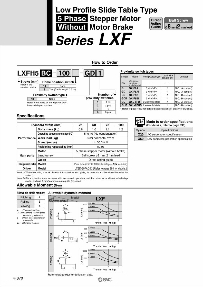
NoneYes (Cable length 0.3 m)
NilS
Home position switch
NoneNil
Proximity switch type
LXFH5 1BC GD
Body mass (kg)
Operating temperature range (°C)
Work load (kg)
Speed (mm/s)
Positioning repeatability (mm)
Motor
Lead screw
Guide
Model
Model
250.8
501.0
751.1
1001.2
5 to 40 (No condensation)
3 (2) horizontal Note 1)
to 30 Note 2)
±0.03
5 phase stepper motor (without brake)
Ball screw ø8 mm, 2 mm lead
Direct acting guide
Photo micro sensor EE-SX672 (Refer to page 1084 for details.)
LC6D-507AD-� (Refer to page 964 for details.)
Performance
Main parts
Home position switch
Driver
Standard stroke (mm)
Proximity switch types
1 pc.2 pcs.
6 pcs.
12
6
Number ofproximity switches
Specifications
Allowable Moment (N·m)
Allowable static momentPitching
Rolling
Yawing
4
3
4m : Transfer load (kg)L1, L2 : Overhang to work piece
center of gravity (mm)a : Work piece acceleration
(mm/sec2)Me : Dynamic moment
Allowable dynamic moment
LXFModelLoadmovement direction
Refer to page 962 for deflection data.
2000
1000
30
30
30
2000
200
1000
100
1 2
1 2
21
300
a = 1000
a = 2000
a = 3000
a = 1000
a = 2000
a = 3000
a = 1000
a = 2000
a = 3000
a
Mep
L1
m
L2
Mer
m
L2
Mey
m
a
Transfer load m (kg)
L1
(mm
)
Transfer load m (kg)
L2
(mm
)
Transfer load m (kg)
L2
(mm
)
Symbol
GGDGBGDBGUGUB
GNWith sensor rail withoutproximity switch
GX-F8AGX-F8AIGX-F8BGX-F8BIGXL-8FUGXL-8FUB
Model Wiring/Output type
3 wire/NPN3 wire/NPN3 wire/NPN3 wire/NPN
2 wire/solid state2 wire/solid state
Lead wirelength (m)
111111
Contact
N.O. (A contact)N.O. (A contact)N.C. (B contact)N.C. (B contact)N.O. (A contact)N.C. (B contact)
∗ Refer to page 1082 for detailed specifications of proximity switches.
Note 1) When mounting a work piece to the actuator's end plate, its mass should be within the value in-side ( ).
Note 2) Since vibration may increase with low speed operation, set the driver to be driven in half-step mode, and use 2 mm/s or more as a guide for speed.
100
… …
Pitc
hing
Rol
ling
Yaw
ing
Stroke (mm)Refer to thestandard stroke.
Refer to the table on the right for prox-imity switch part numbers.
Made to order specifications(For details, refer to page 999)
Symbol Specifications
AC servomotor specification
Low particulate generation specification
X20X60
Made toOrder
Low Profile Slide Table Type 5 Phase Stepper Motor Without Motor Brake
Series LXF
870
How to Order
Ball Screw
ø8 mm/2 mm lead
DirectActingGuide

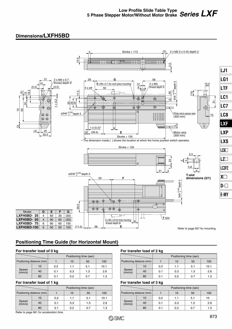
For transfer load of 0 kg
Positioning Time Guide (for Horizontal Mount)
Positioning time (sec)
Positioning distance (mm)
Speed(mm/s)
10
20
30
1
0.2
0.1
0.1
10
1.1
0.6
0.4
50
5.1
2.6
1.7
100
10.1
5.1
3.4
For transfer load of 2 kgPositioning time (sec)
Positioning distance (mm)
Speed(mm/s)
10
20
30
1
0.2
0.1
0.1
10
1.1
0.6
0.4
50
5.1
2.6
1.7
100
10.1
5.1
3.4
For transfer load of 1 kgPositioning time (sec)
Positioning distance (mm)
Speed(mm/s)
10
20
30
1
0.2
0.1
0.1
10
1.1
0.6
0.4
50
5.1
2.6
1.7
100
10.1
5.1
3.4
For transfer load of 3 kgPositioning time (sec)
Positioning distance (mm)
Speed(mm/s)
10
20
30
1
0.2
0.1
0.1
10
1.1
0.6
0.4
50
5.1
2.6
1.7
100
10.1
5.1
3.4
D x M4 x 0.7 (for work piece mounting)
ø5H9+0.030 0 depth 5
2 x M3thread depth 5
321
241
Stroke + 126
10 (39.5) E
17.5
22253528
50
G
6
58
(6)
8
Stroke + 135
10.5
Stroke + 113
2.5
18.5
1020
(5)
627212
(5.5)10
31
(3.5)
1 ±
0.2
25(4)30.5
136
Motor wire(300 mm)
Photo micro sensor wire(300 mm)
4 x ø8
6T-slot
59 F
29.5
4 x M5 x 0.8 (for body mounting)thread depth 8
Refer to page 957 for mounting.(11.5) 38 E
∗ The dimension inside [ ] shows the location at which the home position switch operates.
1.5 [5.5]∗
12
10
31
(15)
10.5
5.88
5 3
T-slotdimensions (2/1)
3.3
(5) 2 x M2.5 x 0.45 depth 2
Refer to page 961 for acceleration time.
ModelLXFH5BC- 25LXFH5BC- 50LXFH5BC- 75LXFH5BC-100
D4466
E60909090
F30606060
G(50)(50)100100
2 x M4 x 0.7 thread depth 9
5H9
+0.
030
0de
pth
5
5H9
+0.
030
0de
pth
5
ø5H9 +0.030 0 depth 5
871
Series LXF
Dimensions/LXFH5BC
Low Profile Slide Table Type5 Phase Stepper Motor/Without Motor Brake
LJ1
LG1
LTF
LC1
LC7
LC8
LXF
LXP
LXS
LC6�
LZ�
LC3F2
X�
D-�
E-MY
P0869-P0877-E.qxd 10.12.15 11:50 AM Page 871

Ball Screw
ø8 mm/5 mm lead
DirectActingGuide
NoneYes (Cable length 0.3 m)
NilS
Home position switch
100
NoneNil
Proximity switch type
LXFH5 1BD GD
1 pc.2 pcs.
6 pcs.
12
6
Number ofproximity switches
Specifications
Allowable Moment (N·m)
Allowable static momentPitching
Rolling
Yawing
4
3
4m : Transfer load (kg)L1, L2 : Overhang to work piece
center of gravity (mm)a : Work piece acceleration
(mm/sec2)Me : Dynamic moment
Allowable dynamic moment
LXFModelLoadmovement direction
Refer to page 962 for deflection data.
2000
1000
30
30
30
2000
200
1000
100
1 2
1 2
21
300
a = 1000
a = 2000
a = 3000
a = 1000
a = 2000
a = 3000
a = 1000
a = 2000
a = 3000
a
Mep
L1
m
L2
Mer
m
L2
Mey
m
a
Transfer load m (kg)
L1
(mm
)
Transfer load m (kg)
L2
(mm
)
Transfer load m (kg)
L2
(mm
)
……
Proximity switch types
Symbol
GGDGBGDBGUGUB
GNWith sensorrail withoutproximity switch
GX-F8AGX-F8AIGX-F8BGX-F8BIGXL-8FUGXL-8FUB
Model Wiring/Output type
3 wire/NPN3 wire/NPN3 wire/NPN3 wire/NPN
2 wire/solid state2 wire/solid state
Lead wirelength (m)
111111
Contact
N.O. (A contact)N.O. (A contact)N.C. (B contact)N.C. (B contact)N.O. (A contact)N.C. (B contact)
∗ Refer to page 1082 for detailed specifications of proximity switches.
Body mass (kg)
Operating temperature range (°C)
Work load (kg)
Speed (mm/s)
Positioning repeatability (mm)
Motor
Lead screw
Guide
Model
Model
250.8
501.0
751.1
1001.2
5 to 40 (No condensation)
3 (2) horizontal Note 1)
to 80 Note 2)
±0.03
5 phase stepper motor (without brake)
Ball screw ø8 mm, 5 mm lead
Direct acting guide
Photo micro sensor EE-SX672 (Refer to page 1084 for details.)
LC6D-507AD-� (Refer to page 964 for details.)
Performance
Main parts
Home position switch
Driver
Standard stroke (mm)
Pitc
hing
Rol
ling
Yaw
ing
Stroke (mm)Refer to thestandard stroke.
Refer to the table on the right for prox-imity switch part numbers.
Made to order specifications(For details, refer to page 999)
Symbol Specifications
AC servomotor specification
Low particulate generation specification
X20X60
Made toOrder
Note 1) When mounting a work piece to the actuator's end plate, its mass should be within the value in-side ( ).
Note 2) Since vibration may increase with low speed operation, set the driver to be driven in half-step mode, and use 5 mm/s or more as a guide for speed.
872
How to Order
Series LXF
Low Profile Slide Table Type 5 Phase Stepper Motor Without Motor Brake
For transfer load of 0 kgPositioning time (sec)
Positioning distance (mm)
Speed(mm/s)
10
40
80
1
0.2
0.1
0.1
10
1.1
0.3
0.2
50
5.1
1.3
0.7
100
10.1
2.6
1.3
For transfer load of 2 kgPositioning time (sec)
Positioning distance (mm)
Speed(mm/s)
10
40
80
1
0.2
0.1
0.1
10
1.1
0.3
0.2
50
5.1
1.3
0.7
100
10.1
2.6
1.3
For transfer load of 1 kgPositioning time (sec)
Positioning distance (mm)
Speed(mm/s)
10
40
80
1
0.2
0.1
0.1
10
1.1
0.3
0.2
50
5.1
1.3
0.7
100
10.1
2.6
1.3
For transfer load of 3 kgPositioning time (sec)
Positioning distance (mm)
Speed(mm/s)
10
40
80
1
0.2
0.1
0.1
10
1.1
0.3
0.2
50
5.1
1.3
0.7
100
10
2.6
1.3
D x M4 x 0.7 (for work piece mounting)
2 x M4 x 0.7thread depth 9 2 x M3
thread depth 5
32124
1
Stroke + 126
10 (39.5) E
17.5
222535
28
50
G
6
58
(6)
8
Stroke + 135
10.5
5
113
2.5
18.5
1020
(5)
627212
(5.5)10
31
(3.5)
1 ±
0.2
25(4)30.5
136
Motor wire(300 mm)
Photo micro sensor wire(300 mm)
4 x ø8
6
59 F
29.5
4 x M5 x 0.8 (for body mounting)thread depth 8
Refer to page 957 for mounting.(11.5) 38 E
∗ The dimension inside [ ] shows the location at which the home position switch operates.
1.5 [5.5]∗
12
10
31
(15)
10.5
5.88
5 3
T-slotdimensions (2/1)
3.3
(5) 2 x M2.5 x 0.45 depth 2
ModelLXFH5BD- 25LXFH5BD- 50LXFH5BD- 75LXFH5BD-100
D4466
E60909090
F30606060
G(50)(50)100100
Refer to page 961 for acceleration time.
T-slot
Positioning Time Guide (for Horizontal Mount)
Stroke + 113
ø5H9 +0.030 0 depth 5
5H9
+0.0
30 0
dept
h 5
5H9
+0.0
30 0
dept
h 5
873
Series LXF
Dimensions/LXFH5BD
ø5H9 +0.030 0 depth 5
Low Profile Slide Table Type5 Phase Stepper Motor/Without Motor Brake
LJ1
LG1
LTF
LC1
LC7
LC8
LXF
LXP
LXS
LC6�
LZ�
LC3F2
X�
D-�
E-MY
P0869-P0877-E.qxd 10.12.15 11:50 AM Page 873

Body mass (kg)
Operating temperature range (°C)
Work load (kg)
Speed (mm/s)
Positioning repeatability (mm)
Motor
Lead screw
Guide
Model
Model
250.8
501.0
751.1
1001.2
5 to 40 (No condensation)
3 (2) horizontal Note 1)
to 100 Note 2)
±0.05
5 phase stepper motor (without brake)
Slide screw ø8 mm, 6 mm lead
Direct acting guide
Photo micro sensor EE-SX672 (Refer to page 1084 for details.)
LC6D-507AD-� (Refer to page 964 for details.)
Performance
Main parts
Home position switch
Driver
Standard stroke (mm)
NoneYes (Cable length 0.3 m)
NilS
Home position switch
NoneNil
Auto/Proximity switch type
LXFH5 1SA
Specifications
Auto switch types
NilM9NM9PM9BF9GF9HF9GLF9HLM9NLM9PLM9BL
D-M9ND-M9PD-M9BD-F9GD-F9HD-F9GLD-F9HLD-M9NLD-M9PLD-M9BL
Model
3 wire/NPN3 wire/PNP
2 wire3 wire/NPN3 wire/NPN3 wire/PNP3 wire/NPN3 wire/PNP3 wire/PNP
2 wire
0.50.50.50.50.53 3 3 3 3
N.O. (A contact)N.O. (A contact)N.O. (A contact)N.C. (B contact)N.C. (B contact)N.C. (B contact)N.C. (B contact)N.O. (A contact)N.O. (A contact)N.O. (A contact)
Proximity switch types
Symbol
GGDGBGDBGUGUB
GNWith sensorrail withoutproximity switch
GX-F8AGX-F8AIGX-F8BGX-F8BIGXL-8FUGXL-8FUB
Model Wiring/Output type
3 wire/NPN3 wire/NPN3 wire/NPN3 wire/NPN
2 wire/solid state2 wire/solid state
Lead wirelength (m)
111111
Contact
N.O. (A contact)N.O. (A contact)N.C. (B contact)N.C. (B contact)N.O. (A contact)N.C. (B contact)
∗ Refer to page 1082 for detailed specifications of proximity switches.
Without auto switch
M9N
Allowable Moment (N·m)
Allowable static momentPitching
Rolling
Yawing
4
3
4m : Transfer load (kg)L1, L2 : Overhang to work piece
center of gravity (mm)a : Work piece acceleration
(mm/sec2)Me : Dynamic moment
Allowable dynamic moment
LXFModelLoadmovement direction
Refer to page 962 for deflection data.
2000
1000
30
30
30
2000
200
1000
100
1 2
1 2
21
300
a = 1000
a = 2000
a = 3000
a = 1000
a = 2000
a = 3000
a = 1000
a = 2000
a = 3000
a
Mep
L1
m
L2
Mer
m
L2
Mey
m
a
Transfer load m (kg)
L1
(mm
)
Transfer load m (kg)
L2
(mm
)
Transfer load m (kg)
L2
(mm
)Number of auto/proximity switches
1 pc.2 pcs.
6 pcs.
12
6
Note 1) When mounting a work piece to the actuator's end plate, its mass should be within the value inside ( ).Note 2) Since vibration may increase with low speed operation, set the driver to be driven in half-step mode, and
use 6 mm/s or more as a guide for speed.
100
Refer to the table on the right for auto/proximity switch part numbers.
… …
When using both auto and proximity switches, list the proximity switch part number after the auto switch part number.Example) M9N1G2
Lead wirelength (m)Symbol Wiring/Output type Contact
Pitc
hing
Rol
ling
Yaw
ing
Stroke (mm)Refer to thestandard stroke.
874
Series LXFHow to Order
Ball Screw
ø8 mm/6 mm lead
DirectActingGuide
Low Profile Slide Table Type 5 Phase Stepper Motor Without Motor Brake

For transfer load of 0 kgPositioning time (sec)
Positioning distance (mm)
Speed(mm/s)
10
50
100
1
0.2
0.1
0.1
10
1.1
0.3
0.2
50
5.1
1.1
0.6
100
10.1
2.1
1.1
For transfer load of 2 kgPositioning time (sec)
Positioning distance (mm)
Speed(mm/s)
10
50
100
1
0.2
0.1
0.1
10
1.1
0.3
0.3
50
5.1
1.1
0.7
100
10.1
2.1
1.2
For transfer load of 1 kgPositioning time (sec)
Positioning distance (mm)
Speed(mm/s)
10
50
100
1
0.2
0.1
0.1
10
1.1
0.3
0.2
50
5.1
1.1
0.6
100
10.1
2.1
1.1
For transfer load of 3 kgPositioning time (sec)
Positioning distance (mm)
Speed(mm/s)
10
50
100
1
0.2
0.1
0.1
10
1.1
0.3
0.3
50
5.1
1.1
0.7
100
10.1
2.1
1.2
D x M4 x 0.7 (for work piece mounting)
2 x M4 x 0.7thread depth 9 2 x M3
thread depth 5
32124
1
Stroke + 126
10 (39.5) E
17.5
222535
28
50
G
6
58
(6)
8
Stroke + 135
10.5
5 Stroke + 113
2.5
18.5
1020
(5)
627212
(5.5)10
31
(3.5)
1 ±
0.2
25(4)30.5
136
Motor wire(300 mm)
Photo micro sensor wire(300 mm)
4 x ø8
6
59 F
29.5
4 x M5 x 0.8 (for body mounting)Thread depth 8
Refer to page 957 for mounting.(11.5) 38 E
∗ The dimension inside [ ] shows the location at which the home position switch operates.
1.5 [5.5]∗
12
10
31
(15)
10.5
5.88
5 3
T-slotdimensions (2/1)
3.3
(5) 2 x M2.5 x 0.45 depth 2
ModelLXFH5SA- 25LXFH5SA- 50LXFH5SA- 75LXFH5SA-100
D4466
E60909090
F30606060
G(50)(50)100100
Refer to page 960 for acceleration time.
T-slot
ø5H9+0.030 0 depth 5
5H9
+0.0
30 0
dept
h 5
5H9
+0.0
30 0
dept
h 5
ø5H9 +0.030 0 depth 5
875
Dimensions/LXFH5SA
Positioning Time Guide (for Horizontal Mount)
Series LXFLow Profile Slide Table Type5 Phase Stepper Motor/Without Motor Brake
LJ1
LG1
LTF
LC1
LC7
LC8
LXF
LXP
LXS
LC6�
LZ�
LC3F2
X�
D-�
E-MY
P0869-P0877-E.qxd 10.12.15 11:50 AM Page 875

Slide Screw
ø8 mm/12 mm lead
DirectActingGuide
250.8
501.0
751.1
1001.2
Performance
Main parts
Home position switch
Driver
Standard stroke (mm)
NoneYes (Cable length 0.3 m)
NilS
Home position switch
NoneNil
Auto/Proximity switch type
LXFH5 1SB
Specifications
M9N
When using both auto and proximity switches, list the proximity switch part number after the auto switch part number.Example) M9N1G2
Allowable static moment Allowable dynamic moment
LXF
Refer to page 962 for deflection data.
2000
1000
30
30
30
2000
200
1000
100
1 2
1 2
21
300
a = 1000
a = 2000
a = 3000
a = 1000
a = 2000
a = 3000
a = 1000
a = 2000
a = 3000
L1
(mm
)L
2 (m
m)
L2
(mm
)Number of auto/proximity switches
12
6
100
Refer to the table on the right for auto/proximity switch part numbers.
1 pc.2 pcs.
6 pcs.
5 to 40 (No condensation)
2 (2) horizontal Note 1)
to 200 Note 2)
±0.05
5 phase stepper motor (without brake)
Slide screw ø8 mm, 12 mm lead
Direct acting guide
Photo micro sensor EE-SX672 (Refer to page 1084 for details.)
LC6D-507AD-� (Refer to page 964 for details.)
Allowable Moment (N·m)
Pitching
Rolling
Yawing
4
3
4
m : Transfer load (kg)L1, L2 : Overhang to work piece
center of gravity (mm)a : Work piece acceleration
(mm/sec2)Me : Dynamic moment
a
Mep
L1
m
L2
Mer
m
L2
Mey
m
a
……
Body mass (kg)
Operating temperature range (°C)
Work load (kg)
Speed (mm/s)
Positioning repeatability (mm)
Motor
Lead screw
Guide
Model
Model
Pitc
hing
Rol
ling
Yaw
ing
ModelLoadmovement direction
Transfer load m (kg)
Transfer load m (kg)
Transfer load m (kg)
Auto switch types
NilM9NM9PM9BF9GF9HF9GLF9HLM9NLM9PLM9BL
D-M9ND-M9PD-M9BD-F9GD-F9HD-F9GLD-F9HLD-M9NLD-M9PLD-M9BL
Model
3 wire/NPN3 wire/PNP
2 wire3 wire/NPN3 wire/PNP3 wire/NPN3 wire/PNP3 wire/NPN3 wire/PNP
2 wire
0.50.50.50.50.53 3 3 3 3
N.O. (A contact)N.O. (A contact)N.O. (A contact)N.C. (B contact)N.C. (B contact)N.C. (B contact)N.C. (B contact)N.O. (A contact)N.O. (A contact)N.O. (A contact)
Proximity switch types
Symbol
GGDGBGDBGUGUB
GNWith sensor rail withoutproximity switch
GX-F8AGX-F8AIGX-F8BGX-F8BIGXL-8FUGXL-8FUB
Model Wiring/Output type
3 wire/NPN3 wire/NPN3 wire/NPN3 wire/NPN
2 wire/solid state2 wire/solid state
Lead wirelength (m)
111111
Contact
N.O. (A contact)N.O. (A contact)N.C. (B contact)N.C. (B contact)N.O. (A contact)N.C. (B contact)
∗ Refer to page 1082 for detailed specifications of proximity switches.
Without auto switch
Lead wirelength (m)Symbol Wiring/Output type Contact
Stroke (mm)Refer to thestandard stroke.
Note 1) When mounting a work piece to the actuator's end plate, its mass should be within the value inside ( ).Note 2) Since vibration may increase with low speed operation, set the driver to be driven in half-step mode, and
use 12 mm/s or more as a guide for speed.
876
How to Order
Series LXF
Low Profile Slide Table Type 5 Phase Stepper Motor Without Motor Brake
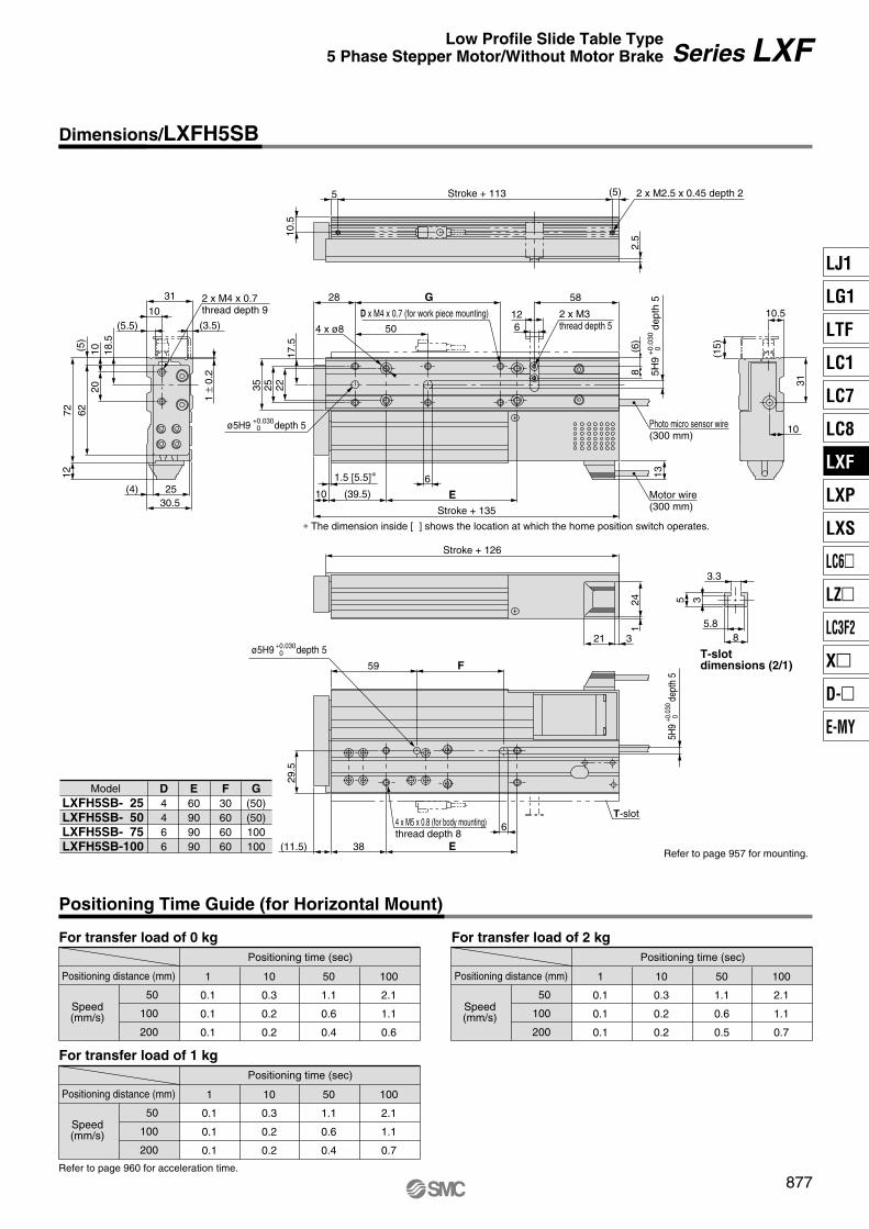
For transfer load of 0 kgPositioning time (sec)
Positioning distance (mm)
Speed(mm/s)
50
100
200
1
0.1
0.1
0.1
10
0.3
0.2
0.2
50
1.1
0.6
0.4
100
2.1
1.1
0.6
For transfer load of 2 kgPositioning time (sec)
Positioning distance (mm)
Speed(mm/s)
50
100
200
1
0.1
0.1
0.1
10
0.3
0.2
0.2
50
1.1
0.6
0.5
100
2.1
1.1
0.7
For transfer load of 1 kgPositioning time (sec)
Positioning distance (mm)
Speed(mm/s)
50
100
200
1
0.1
0.1
0.1
10
0.3
0.2
0.2
50
1.1
0.6
0.4
100
2.1
1.1
0.7
D x M4 x 0.7 (for work piece mounting)
2 x M4 x 0.7thread depth 9 2 x M3
thread depth 5
32124
1
Stroke + 126
10 (39.5) E
17.5
222535
28
50
G
6
58
(6)
8
Stroke + 135
10.5
5 Stroke + 113
2.5
18.5
1020
(5)
627212
(5.5)10
31
(3.5)
1 ±
0.2
25(4)30.5
136
Motor wire(300 mm)
Photo micro sensor wire(300 mm)
4 x ø8
6
59 F
29.5
4 x M5 x 0.8 (for body mounting)thread depth 8
Refer to page 957 for mounting.(11.5) 38 E
∗ The dimension inside [ ] shows the location at which the home position switch operates.
1.5 [5.5]∗
12
10
31
(15)
10.5
5.88
5 3
T-slotdimensions (2/1)
3.3
(5) 2 x M2.5 x 0.45 depth 2
Refer to page 960 for acceleration time.
ModelLXFH5SB- 25LXFH5SB- 50LXFH5SB- 75LXFH5SB-100
D4466
E60909090
F30606060
G(50)(50)100100
T-slot
ø5H9 +0.030 0 depth 5
5H9
+0.
030
0de
pth
5
5H9
+0.0
30 0
dept
h 5
ø5H9 +0.030 0 depth 5
877
Series LXF
Positioning Time Guide (for Horizontal Mount)
Dimensions/LXFH5SB
Low Profile Slide Table Type5 Phase Stepper Motor/Without Motor Brake
LJ1
LG1
LTF
LC1
LC7
LC8
LXF
LXP
LXS
LC6�
LZ�
LC3F2
X�
D-�
E-MY
P0869-P0877-E.qxd 10.12.15 11:50 AM Page 877
NoneYes (Cable length 0.3 m)
NilS
Home position switch
Auto switch type
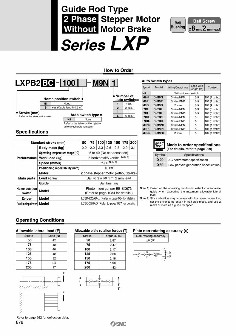
LXPB2 1BC
Specifications
M9N
Body mass (kg)
Operating temperature range (°C)
Work load (kg)
Speed (mm/s)
Positioning repeatability (mm)
Motor
Lead screw
Guide
Model
Model
Model
502.0
752.2
1002.3
1252.6
1502.8
1752.9
2003.1
Performance
Main parts
Home positionswitch
Driver
Positioning driver
Standard stroke (mm)
5 to 40 (No condensation)
6 horizontal/5 vertical Note 1)
to 30 Note 2)
±0.03
2 phase stepper motor (without brake)
Ball screw ø8 mm, 2 mm lead
Ball bushing
Photo micro sensor EE-SX673(Refer to page 1084 for details.)
LC6D-220AD-� (Refer to page 964 for details.)
LC6C-220AD (Refer to page 967 for details.)
Operating Conditions
Stroke
50 75100125150175200
Load (N)
42
42
40
42
32
24
17
Allowable lateral load (F)Stroke
50 75100125150175200
Torque (N⋅m)
2.87
2.47
2.17
2.38
2.16
1.98
1.82
Allowable plate rotation torque (T)Non-rotating accuracy
±0.09°
Plate non-rotating accuracy (θ)
F
TF
+θ–θ
Refer to page 962 for deflection data.
NoneNil
1 pc.2 pcs.
6 pcs.
12
6
Number ofauto switches
Note 1) Based on the operating conditions, establish a separate guide when exceeding the maximum allowable lateral load.
Note 2) Since vibration may increase with low speed operation, set the driver to be driven in half-step mode, and use 2 mm/s or more as a guide for speed.
100 Auto switch types
NilM9NM9PM9BF9GF9HF9GLF9HLM9NLM9PLM9BL
D-M9ND-M9PD-M9BD-F9GD-F9HD-F9GLD-F9HLD-M9NLD-M9PLD-M9BL
Model Wiring/Output type
3 wire/NPN3 wire/PNP
2 wire3 wire/NPN3 wire/PNP3 wire/NPN3 wire/PNP3 wire/NPN3 wire/PNP
2 wire
0.50.50.50.50.53 3 3 3 3
Contact
N.O. (A contact)N.O. (A contact)N.O. (A contact)N.C. (B contact)N.C. (B contact)N.C. (B contact)N.C. (B contact)N.O. (A contact)N.O. (A contact)N.O. (A contact)
Without auto switch
Symbol
Made to order specifications(For details, refer to page 999)
Symbol Specifications
AC servomotor specification
Low particle generation specification
X20X60
Made toOrder
… …
Lead wirelength (m)
878
How to Order
BallBushing
Ball Screw
ø8 mm/2 mm lead
Guide Rod Type 2 Phase Stepper Motor Without Motor Brake
Series LXP
Stroke (mm)Refer to the standard stroke.
Refer to the table on the right for auto switch part numbers.
P0878-P0909-E.qxd 10.12.15 11:50 AM Page 878

For transfer load of 0 kgPositioning time (sec)
Positioning distance (mm)
Speed(mm/s)
10
20
30
1
0.2
0.1
0.1
10
1.1
0.6
0.4
50
5.1
2.6
1.7
100
10.1
5.1
3.4
200
20.1
10.1
6.7
For transfer load of 3 kgPositioning time (sec)
Positioning distance (mm)
Speed(mm/s)
10
20
30
1
0.2
0.7
0.1
10
1.1
0.6
0.4
50
5.1
2.6
1.7
100
10.1
5.1
3.4
200
20.1
10.1
6.7
4 x M6 x 1
Cross section BB
Section C detail(Scale: 2/1)
Section F detail(Scale: 2/1)
B
B
18
30.5
3464
10
10
3
6
4.5 ø4H
9+
0.03
0 0
4H9 +0.030 0
38
4.5
9
50
1
7.5
12
43
5.5
5.4
8.4
4 x
ø9.
54
x ø
5.6
+0.
1 0
49
4 x M6 x 130 D
34
E
D
Photo micro sensor wire (300 mm)Motor wire (300 mm)
Section C
2663
73
3478919447
.5
21.5
∗ The dimension inside [ ] shows the location at which the home position switch operates.
ModelLXPB2BC- 50LXPB2BC- 75LXPB2BC-100LXPB2BC-125LXPB2BC-150LXPB2BC-175LXPB2BC-200
D
44
120
E
52
90
Refer to page 958 for mounting.
For transfer load of 6 kgPositioning time (sec)
Positioning distance (mm)
Speed(mm/s)
10
20
30
1
0.2
0.1
0.1
10
1.1
0.6
0.4
50
5.1
2.6
1.7
200
20.1
10.1
6.7
100
10.1
5.1
3.4
Refer to page 961 for acceleration time.
523.56
1
14.5
Section F
30
Section C
+0.030
0
depth 6
ø4H9
ø4H9+0.
030
0
dept
h 6
10 [16.5] ∗
Stroke + 181 (Stroke: 50 to 100 mm)Stroke + 198 (Stroke: 125 to 200 mm)
Stroke + 104 (Stroke: 50 to 100 mm)Stroke + 121 (Stroke: 125 to 200 mm)
4 x M6 x 1 depth 10
879
Positioning Time Guide (for Horizontal Mount)
Dimensions/LXPB2BC
Series LXPGuide Rod Type2 Phase Stepper Motor/Without Motor Brake
LJ1
LG1
LTF
LC1
LC7
LC8
LXF
LXP
LXS
LC6�
LZ�
LC3F2
X�
D-�
E-MY
P0878-P0909-E.qxd 10.12.15 11:50 AM Page 879

LXPB2 1BD
Specifications
M9N
Body mass (kg)
Operating temperature range (°C)
Work load (kg)
Speed (mm/s)
Positioning repeatability (mm)
Motor
Lead screw
Guide
Model
Model
Model
502.0
752.2
1002.3
1252.6
1502.8
1752.9
2003.1
Performance
Main parts
Home positionswitch
Driver
Positioning driver
5 to 40 (No condensation)
6 horizontal/5 vertical Note 1)
to 80 Note 2)
±0.03
2 phase stepper motor (without brake)
Ball screw ø8 mm, 5 mm lead
Ball bushing
Photo micro sensor EE-SX673(Refer to page 1084 for details.)
LC6D-220AD-� (Refer to page 964 for details.)
LC6C-220AD (Refer to page 967 for details.)
Stroke
50 75100125150175200
Load (N)
42
42
40
42
32
24
17
Stroke
50 75100125150175200
Torque (N⋅m)
2.87
2.47
2.17
2.38
2.16
1.98
1.82
Non-rotating accuracy
±0.09°
F
TF
100
NoneYes (Cable length 0.3 m)
NilS
Home position switch
Auto switch typeNoneNil
1 pc.2 pcs.
6 pcs.
12
6
Number ofauto switches
… …
Stroke (mm)Refer to the standard stroke.
Auto switch types
NilM9NM9PM9BF9GF9HF9GLF9HLM9NLM9PLM9BL
D-M9ND-M9PD-M9BD-F9GD-F9HD-F9GLD-F9HLD-M9NLD-M9PLD-M9BL
Wiring/Output type
3 wire/NPN3 wire/PNP
2 wire3 wire/NPN3 wire/PNP3 wire/NPN3 wire/PNP3 wire/NPN3 wire/PNP
2 wire
0.50.50.50.50.53 3 3 3 3
Contact
N.O. (A contact)N.O. (A contact)N.O. (A contact)N.C. (B contact)N.C. (B contact)N.C. (B contact)N.C. (B contact)N.O. (A contact)N.O. (A contact)N.O. (A contact)
Without auto switch
Made to order specifications(For details, refer to page 999)
Symbol Specifications
AC servomotor specification
Low particle generation specification
X20X60
Made toOrder
Standard stroke (mm)
Operating Conditions
Allowable lateral load (F) Allowable plate rotation torque (T) Plate non-rotating accuracy (θ)
+θ–θ
Refer to page 962 for deflection data.
Refer to the table on the right for auto switch part numbers.
ModelSymbol Lead wirelength (m)
Note 1) Based on the operating conditions, establish a separate guide when exceeding the maximum allowable lateral load.
Note 2) Since vibration may increase with low speed operation, set the driver to be driven in half-step mode, and use 5 mm/s or more as a guide for speed.
880
BallBushing
Ball Screw
ø8 mm/5 mm lead
How to Order
Guide Rod Type 2 Phase Stepper Motor Without Motor Brake
Series LXP
P0878-P0909-E.qxd 10.12.15 11:50 AM Page 880

10
40
80
1
0.2
0.1
0.1
10
1.1
0.3
0.2
50
5.1
1.3
0.7
100
10.1
2.6
1.3
200
20.1
5.1
2.6
10
40
80
1
0.2
0.1
0.1
10
1.1
0.3
0.2
50
5.1
1.3
0.7
100
10.1
2.6
1.3
200
20.1
5.1
2.6
4 x M6 x 1
Cross section BB
B
B
18
30
30.5
3464
10
10
3
6
4.5
ø4H
9+
0.03
0 0
4H9 +0.030 0
38
4.5
9
50
1
7.5
12
43
5.5
5.4
8.4
4 x
ø9.
54
x ø
5.6
+0.
1 0
49
30 D
34
E
D
Photo micro sensor wire (300 mm)Motor wire (300 mm)
4 x M6 x 1 depth 10Section C
2663
73
3478919447
.5
21.5
∗ The dimension inside [ ] shows the location at which the home position switch operates.
ModelLXPB2BD- 50LXPB2BD- 75LXPB2BD-100LXPB2BD-125LXPB2BD-150LXPB2BD-175LXPB2BD-200
D
44
120
E
52
90
10
40
80
1
0.2
0.1
0.1
10
1.1
0.3
0.2
50
5.1
1.3
0.7
200
20.1
5.1
2.6
100
10.1
2.6
1.3
523.56
1
14.5
Section F
ø4H9+0
.030
0
dept
h 6
10 [16.5] ∗
Stroke + 181 (Stroke: 50 to 100 mm)Stroke + 198 (Stroke: 125 to 200 mm)
Stroke + 104 (Stroke: 50 to 100 mm)Stroke + 121 (Stroke: 125 to 200 mm)
4 x M6 x 1
Refer to page 958 for mounting.
Section C
+0.030
0
depth 6
ø4H9
For transfer load of 0 kgPositioning time (sec)
Positioning distance (mm)
Speed(mm/s)
For transfer load of 3 kgPositioning time (sec)
Positioning distance (mm)
Speed(mm/s)
For transfer load of 6 kgPositioning time (sec)
Positioning distance (mm)
Speed(mm/s)
Refer to page 961 for acceleration time.
Positioning Time Guide (for Horizontal Mount)
Section C detail(Scale: 2/1)
Section F detail(Scale: 2/1)
881
Dimensions/LXPB2BD
Series LXPGuide Rod Type2 Phase Stepper Motor/Without Motor Brake
LJ1
LG1
LTF
LC1
LC7
LC8
LXF
LXP
LXS
LC6�
LZ�
LC3F2
X�
D-�
E-MY
P0878-P0909-E.qxd 10.12.15 11:50 AM Page 881
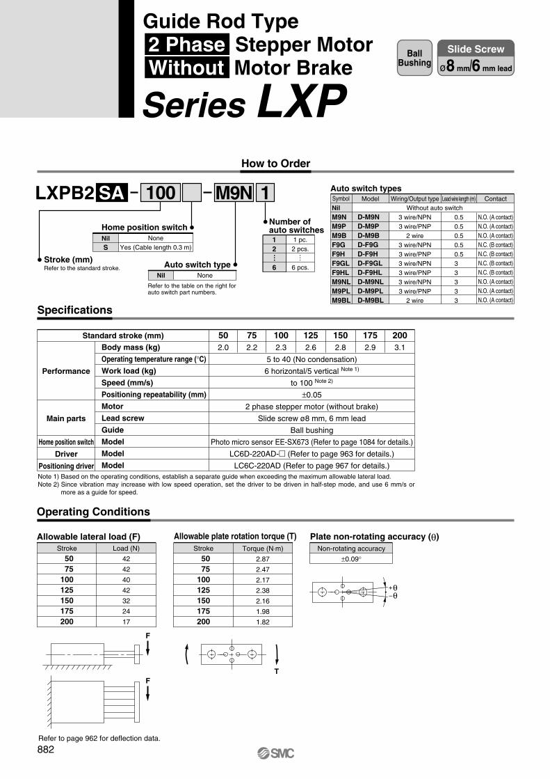
LXPB2 1SA
Specifications
M9N
Body mass (kg)
Operating temperature range (°C)
Work load (kg)
Speed (mm/s)
Positioning repeatability (mm)
Motor
Lead screw
Guide
Model
Model
Model
502.0
752.2
1002.3
1252.6
1502.8
1752.9
2003.1
Performance
Main parts
Home position switch
Driver
Positioning driver
Standard stroke (mm)
5 to 40 (No condensation)
6 horizontal/5 vertical Note 1)
to 100 Note 2)
±0.05
2 phase stepper motor (without brake)
Slide screw ø8 mm, 6 mm lead
Ball bushing
Photo micro sensor EE-SX673 (Refer to page 1084 for details.)
LC6D-220AD-� (Refer to page 963 for details.)
LC6C-220AD (Refer to page 967 for details.)
Operating Conditions
Stroke
50 75100125150175200
Load (N)
42
42
40
42
32
24
17
Allowable lateral load (F)Stroke
50 75100125150175200
Torque (N⋅m)
2.87
2.47
2.17
2.38
2.16
1.98
1.82
Allowable plate rotation torque (T)Non-rotating accuracy
±0.09°
Plate non-rotating accuracy (θ)
F
TF
+θ–θ
Refer to page 962 for deflection data.
100
NoneYes (Cable length 0.3 m)
NilS
Home position switch
Auto switch typeNoneNil
1 pc.2 pcs.
6 pcs.
12
6
Number ofauto switches
… …
Stroke (mm)Refer to the standard stroke.
Auto switch types
NilM9NM9PM9BF9GF9HF9GLF9HLM9NLM9PLM9BL
D-M9ND-M9PD-M9BD-F9GD-F9HD-F9GLD-F9HLD-M9NLD-M9PLD-M9BL
Model Wiring/Output type
3 wire/NPN3 wire/PNP
2 wire3 wire/NPN3 wire/PNP3 wire/NPN3 wire/PNP3 wire/NPN3 wire/PNP
2 wire
Lead wire length (m)
0.50.50.50.50.53 3 3 3 3
Contact
N.O. (A contact)N.O. (A contact)N.O. (A contact)N.C. (B contact)N.C. (B contact)N.C. (B contact)N.C. (B contact)N.O. (A contact)N.O. (A contact)N.O. (A contact)
Without auto switchSymbol
Note 1) Based on the operating conditions, establish a separate guide when exceeding the maximum allowable lateral load.Note 2) Since vibration may increase with low speed operation, set the driver to be driven in half-step mode, and use 6 mm/s or
more as a guide for speed.
Refer to the table on the right for auto switch part numbers.
882
BallBushing
Slide Screw
ø8 mm/6 mm lead
Guide Rod Type 2 Phase Stepper Motor Without Motor Brake
Series LXP How to Order
P0878-P0909-E.qxd 10.12.15 11:50 AM Page 882

For transfer load of 0 kg
Positioning Time Guide (for Horizontal Mount)
Positioning time (sec)
Positioning distance (mm)
Speed(mm/s)
10
50
100
1
0.2
0.1
0.1
10
1.1
0.3
0.2
50
5.1
1.1
0.6
100
10.1
2.1
1.1
200
20.1
4.1
2.1
For transfer load of 3 kgPositioning time (sec)
Positioning distance (mm)
Speed(mm/s)
10
50
100
1
0.2
0.1
0.1
10
1.1
0.3
0.2
50
5.1
1.1
0.6
100
10.1
2.1
1.1
200
20.1
4.1
2.1
4 x M6 x 1Section F
Cross section BB
B
B
18
3030
.53464
10
10
3
6
4.5
ø4H
9+
0.03
0 0
4H9 +0.030 0
38
4.5
9
50
1
7.5
12
43
5.5
5.4
8.4
4 x
ø9.
54
x ø
5.6
+0.
1 0
49
30 D
34
E
D2663
73
3478919447
.5
21.5
∗ The dimension inside [ ] shows the location at which the home position switch operates.
ModelLXPB2SA- 50LXPB2SA- 75LXPB2SA-100LXPB2SA-125LXPB2SA-150LXPB2SA-175LXPB2SA-200
D
44
120
E
52
90
For transfer load of 6 kgPositioning time (sec)
Positioning distance (mm)
Speed(mm/s)
10
50
100
1
0.1
0.1
0.1
10
1.1
0.3
0.2
50
5.1
1.1
0.6
200
20.1
4.1
2.1
100
10.1
2.1
1.1
Refer to page 960 for acceleration time.
523.56
1
14.5
B
4 x M6 x 1 depth 10Section C
ø4H9+0
.030
0
dept
h 6
Photo micro sensor wire (300 mm)Motor wire (300 mm)
10 [16.5] ∗
Stroke + 181 (Stroke: 50 to 100 mm)Stroke + 198 (Stroke: 125 to 200 mm)
Stroke + 104 (Stroke: 50 to 100 mm)Stroke + 121 (Stroke: 125 to 200 mm)
Section C detail(Scale: 2/1)
Section F detail(Scale: 2/1)
4 x M6 x 1
Refer to page 958 for mounting.
Section C
+0.030
0
depth 6
ø4H9
883
Dimensions/LXPB2SA
Series LXPGuide Rod Type2 Phase Stepper Motor/Without Motor Brake
LJ1
LG1
LTF
LC1
LC7
LC8
LXF
LXP
LXS
LC6�
LZ�
LC3F2
X�
D-�
E-MY
P0878-P0909-E.qxd 10.12.15 11:50 AM Page 883

LXPB2 1SB
Specifications
M9N
Body mass (kg)
Operating temperature range (°C)
Work load (kg)
Speed (mm/s)
Positioning repeatability (mm)
Motor
Lead screw
Guide
Model
Model
Model
502.0
752.2
1002.3
1252.6
1502.8
1752.9
2003.1
Performance
Main parts
Home position switch
Driver
Positioning driver
Standard stroke (mm)
5 to 40 (No condensation)
3 horizontal/3 vertical Note 1)
to 200 Note 2)
±0.05
2 phase stepper motor (without brake)
Slide screw ø8 mm, 12 mm lead
Ball bushing
Photo micro sensor EE-SX673 (Refer to page 1084 for details.)
LC6D-220AD-� (Refer to page 963 for details.)
LC6C-220AD (Refer to page 967 for details.)
Operating Conditions
Stroke
50 75100125150175200
Load (N)
42
42
40
42
32
24
17
Allowable lateral load (F)Stroke
50 75100125150175200
Torque (N⋅m)
2.87
2.47
2.17
2.38
2.16
1.98
1.82
Allowable plate rotation torque (T)Non-rotating accuracy
±0.09°
Plate non-rotating accuracy (θ)
F
TF
Refer to page 962 for deflection data.
100
NoneYes (Cable length 0.3 m)
NilS
Home position switch
Auto switch typeNoneNil
1 pc.2 pcs.
6 pcs.
12
6
Number ofauto switches
… …
Stroke (mm)Refer to the standard stroke.
Auto switch types
NilM9NM9PM9BF9GF9HF9GLF9HLM9NLM9PLM9BL
D-M9ND-M9PD-M9BD-F9GD-F9HD-F9GLD-F9HLD-M9NLD-M9PLD-M9BL
Model Wiring/Output type
3 wire/NPN3 wire/PNP
2 wire3 wire/NPN3 wire/PNP3 wire/NPN3 wire/PNP3 wire/NPN3 wire/PNP
2 wire
Lead wire length (m)
0.50.50.50.50.53 3 3 3 3
Contact
N.O. (A contact)N.O. (A contact)N.O. (A contact)N.C. (B contact)N.C. (B contact)N.C. (B contact)N.C. (B contact)N.O. (A contact)N.O. (A contact)N.O. (A contact)
Without auto switchSymbol
Note 1) Based on the operating conditions, establish a separate guide when exceeding the maximum allowable lateral load.Note 2) Since vibration may increase with low speed operation, set the driver to be driven in half-step mode, and use 12 mm/s or
more as a guide for speed.
+θ–θ
Refer to the table on the right for auto switch part numbers.
884
BallBushing
Slide Screw
ø8 mm/12 mm lead
How to Order
Guide Rod Type 2 Phase Stepper Motor Without Motor Brake
Series LXP
P0878-P0909-E.qxd 10.12.15 11:50 AM Page 884
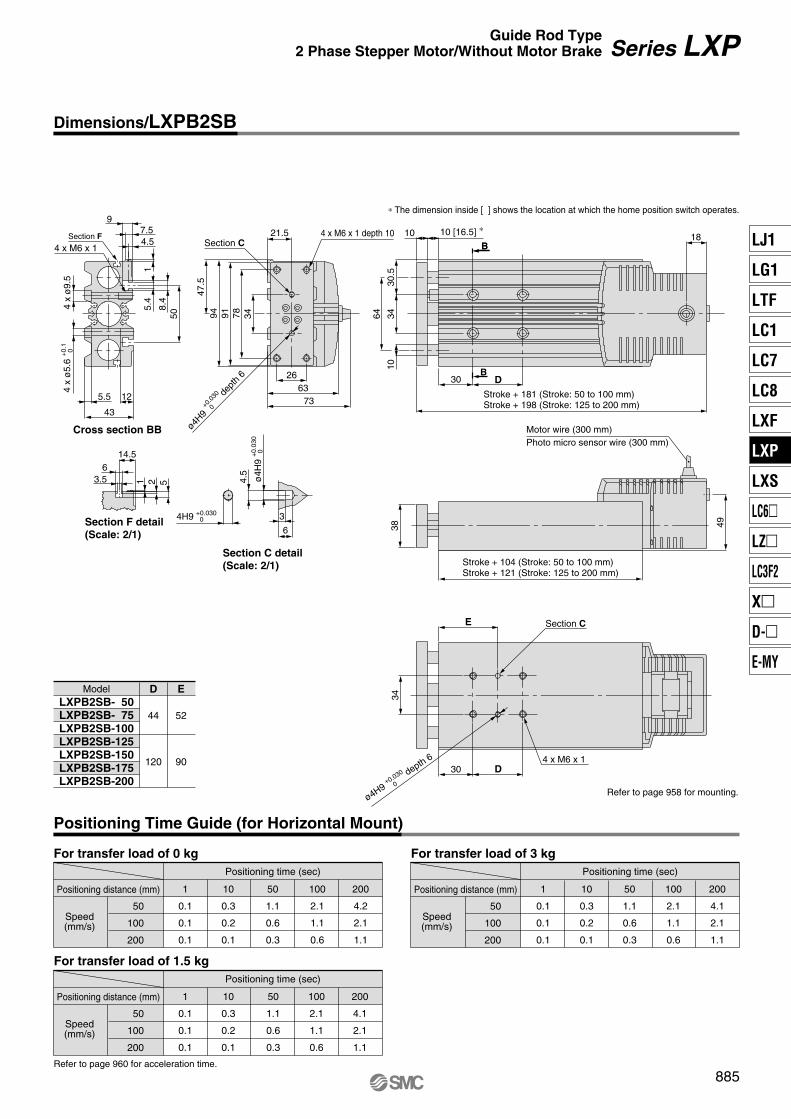
For transfer load of 0 kg
50
100
200
1
0.1
0.1
0.1
10
0.3
0.2
0.1
50
1.1
0.6
0.3
100
2.1
1.1
0.6
200
4.2
2.1
1.1
For transfer load of 1.5 kg
50
100
200
1
0.1
0.1
0.1
10
0.3
0.2
0.1
50
1.1
0.6
0.3
100
2.1
1.1
0.6
200
4.1
2.1
1.1
B
B
18
3030
.53464
10
10
3
6
4.5
ø4H
9+
0.03
0 0
4H9 +0.030 0
38
4.5
9
50
1
7.5
12
43
5.5
5.4
8.4
49
30 D
34
E
D2663
73
3478919447
.5
21.5
ModelLXPB2SB- 50LXPB2SB- 75LXPB2SB-100LXPB2SB-125LXPB2SB-150LXPB2SB-175LXPB2SB-200
D
44
120
E
52
90
For transfer load of 3 kg
50
100
200
1
0.1
0.1
0.1
10
0.3
0.2
0.1
50
1.1
0.6
0.3
200
4.1
2.1
1.1
100
2.1
1.1
0.6
523.56
1
14.5
B4 x M6 x 1 depth 10
Section C
ø4H9+0
.030
0
dept
h 6
∗ The dimension inside [ ] shows the location at which the home position switch operates.
Photo micro sensor wire (300 mm)Motor wire (300 mm)
10 [16.5] ∗
Stroke + 181 (Stroke: 50 to 100 mm)Stroke + 198 (Stroke: 125 to 200 mm)
Stroke + 104 (Stroke: 50 to 100 mm)Stroke + 121 (Stroke: 125 to 200 mm)
4 x M6 x 1
Refer to page 958 for mounting.
Section C
+0.030
0
depth 6
ø4H9
Section C detail(Scale: 2/1)
Section F detail(Scale: 2/1)
885
Dimensions/LXPB2SB
Positioning Time Guide (for Horizontal Mount)
Series LXPGuide Rod Type2 Phase Stepper Motor/Without Motor Brake
4 x M6 x 1Section F
Cross section BB
4 x
ø9.
54
x ø
5.6
+0.
1 0
Positioning time (sec)
Positioning distance (mm)
Speed(mm/s)
Positioning time (sec)
Positioning distance (mm)
Speed(mm/s)
Positioning time (sec)
Positioning distance (mm)
Speed(mm/s)
Refer to page 960 for acceleration time.
LJ1
LG1
LTF
LC1
LC7
LC8
LXF
LXP
LXS
LC6�
LZ�
LC3F2
X�
D-�
E-MY
P0878-P0909-E.qxd 10.12.15 11:50 AM Page 885

LXPB2 1BBC M9N
Body mass (kg)Operating temperature range (°C)Work load (kg)Speed (mm/s)Positioning repeatability (mm)MotorLead screwGuide
Model
ModelModel
502.2
752.4
1002.5
1252.8
1503.0
1753.1
2003.3
5 to 40 (No condensation)6 horizontal/5 vertical Note 1)
to 30 Note 2)
±0.032 phase stepper motor (with brake)
Ball screw ø8 mm, 2 mm leadBall bushing
De-energized operating type0.1 or more24 DC ±5%
5Photo micro sensor EE-SX673
(Refer to page 1084 for details.)LC6D-220AD-� (Refer to page 963 for details.)LC6C-220AD (Refer to page 967 for details.)
Performance
Main parts
Home positionswitchDriver
Positioning driver
Standard stroke (mm)
Electromagneticbrake
ModelStatic torque (N·m)Rated voltage (V)Power consumption (W)
Stroke
50 75100125150175200
Load (N)
42
42
40
42
32
24
17
Allowable lateral load (F)Stroke
50 75100125150175200
Torque (N⋅m)
2.87
2.47
2.17
2.38
2.16
1.98
1.82
Allowable plate rotation torque (T)
Non-rotating accuracy
±0.09°
Plate non-rotating accuracy (θ)
F
F
+θ–θ
This is the operating range for ball bushings.Use within the allowable thrust range.
L
m
L
m
50 to 200 mm stroke
10
1
0.110 50 100
Eccentric distance L (mm)
Load
mas
s m
(kg
)
125 to 200 mm stroke
50 to 100 mm stroke
T
Refer to page 962 for deflection data.
Lifter Operation Range Operating Conditions
Specifications
100
Stroke (mm)Refer to the standard stroke.
NoneYes (Cable length 0.3 m)
NilS
Home position switch
Auto switch typeNoneNil
1 pc.2 pcs.
6 pcs.
12
6
Number ofauto switches
… …
Auto switch types
NilM9NM9PM9BF9GF9HF9GLF9HLM9NLM9PLM9BL
D-M9ND-M9PD-M9BD-F9GD-F9HD-F9GLD-F9HLD-M9NLD-M9PLD-M9BL
Wiring/Output type
3 wire/NPN3 wire/PNP
2 wire3 wire/NPN3 wire/PNP3 wire/NPN3 wire/PNP3 wire/NPN3 wire/PNP
2 wire
0.50.50.50.50.53 3 3 3 3
Contact
N.O. (A contact)N.O. (A contact)N.O. (A contact)N.C. (B contact)N.C. (B contact)N.C. (B contact)N.C. (B contact)N.O. (A contact)N.O. (A contact)N.O. (A contact)
Without auto switch
Made to order specifications(For details, refer to page 999)
Symbol Specifications
X20X60
Made toOrder
ModelSymbol
AC servomotor specification
Low particle generation specification
Lead wirelength (m)
Note 1) Based on the operating conditions, establish a separate guide when exceeding the maximum allowable lateral load.
Note 2) Since vibration may increase with low speed operation, set the driver to be driven in half-step mode, and use 2 mm/s or more as a guide for speed.
886
How to Order
BallBushing
Ball Screw
ø 8 mm/2 mm lead
Guide Rod Type 2 Phase Stepper Motor With Motor Brake
Series LXP
Refer to the table on the right for auto switch part numbers.
P0878-P0909-E.qxd 10.12.15 11:50 AM Page 886

For transfer load of 0 kgPositioning time (sec)
Positioning distance (mm)
Speed(mm/s)
10
20
30
For transfer load of 2.5 kg
1
0.2
0.1
0.1
10
1.1
0.6
0.4
50
5.1
2.6
1.7
200
20.1
10.1
6.7
100
10.1
5.1
3.4
Positioning time (sec)
Positioning distance (mm)
Speed(mm/s)
10
20
30
1
0.2
0.1
0.1
10
1.1
0.6
0.4
50
5.1
2.6
1.7
200
20.1
10.1
6.7
100
10.1
5.1
3.4
3
6
4.5
ø4H
9+
0.03
0 0
4H9 +0.030 0
Section C detail(Scale: 2/1)
Brake electrical circuit+24 V
0 V
Note) A contact protection circuit is required when connecting a brake.
Brown
White
∗ The dimension inside [ ] shows the location at which the home position switch operates.
For transfer load of 5 kgPositioning time (sec)
Positioning distance (mm)
Speed(mm/s)
10
20
30
1
0.2
0.1
0.1
10
1.1
0.6
0.4
50
5.1
2.6
1.7
200
20.1
10.1
6.7
100
10.1
5.1
3.4
Refer to page 961 for acceleration time.
ModelLXPB2BC- 50LXPB2BC- 75LXPB2BC-100LXPB2BC-125LXPB2BC-150LXPB2BC-175LXPB2BC-200
D
44
120
E
52
90
Refer to page 958 for mounting.
Section F detail(Scale: 2/1)
523.56
1
14.5
4 x M6 x 1
Cross section BB
4.5
9
50
1
7.5
12
435.5
5.4
8.4
4 x
ø9.
54
x ø
5.6
+0.
1 0
Section F
26
34789194
47.5
7888
21.5
4 x M6 x 1
Section C
30 D
34
E
38 49
40.5
30.5
3410
10
B
B30 D
64
4 x M6 x 1 depth 10Section C
ø4H9+0
.030
0
dept
h 6
10 [16.5] ∗
Motor wire (300 mm)
Photo micro sensor wire (300 mm)Brake wire (300 mm)
Stroke + 216 (Stroke: 50 to 100 mm)Stroke + 233 (Stroke: 125 to 200 mm)
Stroke + 104 (Stroke: 50 to 100 mm)Stroke + 121 (Stroke: 125 to 200 mm)
ø4H9+0.030
0
depth 6
887
Dimensions/LXPB2BC
Positioning Time Guide (for Vertical Mount)
Series LXPGuide Rod Type2 Phase Stepper Motor/With Motor Brake
LJ1
LG1
LTF
LC1
LC7
LC8
LXF
LXP
LXS
LC6�
LZ�
LC3F2
X�
D-�
E-MY
P0878-P0909-E.qxd 10.12.15 11:50 AM Page 887
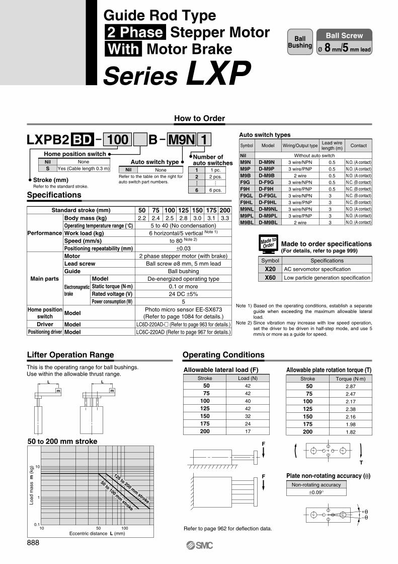
LXPB2 1BBD M9N
Body mass (kg)Operating temperature range (°C)Work load (kg)Speed (mm/s)Positioning repeatability (mm)MotorLead screwGuide
Model
ModelModel
502.2
752.4
1002.5
1252.8
1503.0
1753.1
2003.3
5 to 40 (No condensation)6 horizontal/5 vertical Note 1)
to 80 Note 2)
±0.032 phase stepper motor (with brake)
Ball screw ø8 mm, 5 mm leadBall bushing
De-energized operating type0.1 or more24 DC ±5%
5Photo micro sensor EE-SX673
(Refer to page 1084 for details.)LC6D-220AD-� (Refer to page 963 for details.)LC6C-220AD (Refer to page 967 for details.)
Performance
Main parts
Home positionswitchDriver
Positioning driver
Standard stroke (mm)
Electromagneticbrake
ModelStatic torque (N·m)Rated voltage (V)Power consumption (W)
Specifications
Stroke
50 75100125150175200
Load (N)
42
42
40
42
32
24
17
Allowable lateral load (F)Stroke
50 75100125150175200
Torque (N⋅m)
2.87
2.47
2.17
2.38
2.16
1.98
1.82
Allowable plate rotation torque (T)
Non-rotating accuracy
±0.09°
Plate non-rotating accuracy (θ)
F
F
This is the operating range for ball bushings.Use within the allowable thrust range.
L
m
L
m
50 to 200 mm stroke
10
1
0.110 50 100
T
Refer to page 962 for deflection data.
Lifter Operation Range Operating Conditions
100 Auto switch types
NilM9NM9PM9BF9GF9HF9GLF9HLM9NLM9PLM9BL
D-M9ND-M9PD-M9BD-F9GD-F9HD-F9GLD-F9HLD-M9NLD-M9PLD-M9BL
Wiring/Output type
3 wire/NPN3 wire/PNP
2 wire3 wire/NPN3 wire/PNP3 wire/NPN3 wire/PNP3 wire/NPN3 wire/PNP
2 wire
0.50.50.50.50.53 3 3 3 3
Contact
N.O. (A contact)N.O. (A contact)N.O. (A contact)N.C. (B contact)N.C. (B contact)N.C. (B contact)N.C. (B contact)N.O. (A contact)N.O. (A contact)N.O. (A contact)
Without auto switch
Made to order specifications(For details, refer to page 999)
Symbol Specifications
X20X60
Made toOrder
Eccentric distance L (mm)
Load
mas
s m
(kg
)
125 to 200 mm stroke
50 to 100 mm stroke+θ–θ
ModelSymbol
AC servomotor specification
Low particle generation specification
Lead wirelength (m)
Note 1) Based on the operating conditions, establish a separate guide when exceeding the maximum allowable lateral load.
Note 2) Since vibration may increase with low speed operation, set the driver to be driven in half-step mode, and use 5 mm/s or more as a guide for speed.
888
BallBushing
Ball Screw
ø 8 mm/5 mm lead
How to Order
Stroke (mm)Refer to the standard stroke.
NoneYes (Cable length 0.3 m)
NilS
Home position switchAuto switch type
NoneNil 1 pc.2 pcs.
6 pcs.
12
6
Number ofauto switches
… …Refer to the table on the right for auto switch part numbers.
Guide Rod Type 2 Phase Stepper Motor With Motor Brake
Series LXP
P0878-P0909-E.qxd 10.12.15 11:50 AM Page 888
4.5
9
50
1
7.5
12
435.5
5.4
8.4
26
34789194
47.5
7888
21.5
30 D
34
E
38 49
40.5
30.5
3410
10
B
B30 D
64
10
40
80
1
0.2
0.1
0.1
10
1.1
0.3
0.2
50
5.1
1.3
0.7
200
20.1
5.1
2.6
100
10.1
2.6
1.3
10
40
80
1
0.2
0.1
0.1
10
1.1
0.3
0.2
50
5.1
1.3
0.7
200
20.1
5.1
2.6
100
10.1
2.6
1.3
3
6
4.5
10
40
80
1
0.2
0.1
0.1
10
1.1
0.3
0.2
50
5.1
1.3
0.7
200
20.1
5.1
2.6
100
10.1
2.6
1.3
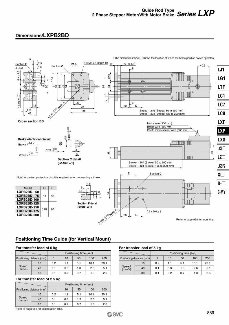
LXPB2BD- 50LXPB2BD- 75LXPB2BD-100LXPB2BD-125LXPB2BD-150LXPB2BD-175LXPB2BD-200
D
44
120
E
52
90
523.56
1
14.5
4 x M6 x 1 depth 10Section C
ø4H9+0
.030
0
dept
h 6
∗ The dimension inside [ ] shows the location at which the home position switch operates.
10 [16.5] ∗
Motor wire (300 mm)
Photo micro sensor wire (300 mm)Brake wire (300 mm)
Stroke + 216 (Stroke: 50 to 100 mm)Stroke + 233 (Stroke: 125 to 200 mm)
Stroke + 104 (Stroke: 50 to 100 mm)Stroke + 121 (Stroke: 125 to 200 mm)
Refer to page 958 for mounting.
4 x M6 x 1
Section C
ø4H9+0.030
0
depth 6
ø4H
9+
0.03
0 0
4H9 +0.030 0
Section C detail(Scale: 2/1)
Brake electrical circuit+24 V
0 V
Brown
White
Note) A contact protection circuit is required when connecting a brake.
Model
Section F detail(Scale: 2/1)
For transfer load of 0 kgPositioning time (sec)
Positioning distance (mm)
Speed(mm/s)
For transfer load of 2.5 kgPositioning time (sec)
Positioning distance (mm)
Speed(mm/s)
For transfer load of 5 kgPositioning time (sec)
Positioning distance (mm)
Speed(mm/s)
Refer to page 961 for acceleration time.
Positioning Time Guide (for Vertical Mount)
889
Dimensions/LXPB2BD
Series LXPGuide Rod Type2 Phase Stepper Motor/With Motor Brake
4 x M6 x 1
Cross section BB
4 x
ø9.
54
x ø
5.6
+0.
1 0
Section F
LJ1
LG1
LTF
LC1
LC7
LC8
LXF
LXP
LXS
LC6�
LZ�
LC3F2
X�
D-�
E-MY
P0878-P0909-E.qxd 10.12.15 11:50 AM Page 889

LXPB2 1BSA M9N
Body mass (kg)Operating temperature range (°C)Work load (kg)Speed (mm/s)Positioning repeatability (mm)MotorLead screwGuide
Model
ModelModel
502.2
752.4
1002.5
1252.8
1503.0
1753.1
2003.3
5 to 40 (No condensation)6 horizontal/5 vertical Note 1)
to 100 Note 2)
±0.052 phase stepper motor (with brake)
Slide screw ø8 mm, 6 mm leadBall bushing
De-energized operating type0.1 or more24 DC ±5%
5Photo micro sensor EE-SX673
(Refer to page 1084 for details.)LC6D-220AD-� (Refer to page 963 for details.)LC6C-220AD (Refer to page 967 for details.)
Performance
Main parts
Home positionswitchDriver
Positioning driver
Electromagneticbrake
ModelStatic torque (N·m)Rated voltage (V)Power consumption (W)
Stroke
50 75100125150175200
Load (N)
42
42
40
42
32
24
17
Stroke
50 75100125150175200
Torque (N⋅m)
2.87
2.47
2.17
2.38
2.16
1.98
1.82
Non-rotating accuracy
±0.09°
F
F
L
m
L
m
10
1
0.110 50 100
T
100 Auto switch types
NilM9NM9PM9BF9GF9HF9GLF9HLM9NLM9PLM9BL
D-M9ND-M9PD-M9BD-F9GD-F9HD-F9GLD-F9HLD-M9NLD-M9PLD-M9BL
Model Wiring/Output type
3 wire/NPN3 wire/PNP
2 wire3 wire/NPN3 wire/PNP3 wire/NPN3 wire/PNP3 wire/NPN3 wire/PNP
2 wire
0.50.50.50.50.53 3 3 3 3
Lead wirelength (m) Contact
N.O. (A contact)N.O. (A contact)N.O. (A contact)N.C. (B contact)N.C. (B contact)N.C. (B contact)N.C. (B contact)N.O. (A contact)N.O. (A contact)N.O. (A contact)
Without auto switch
Symbol
Specifications
Standard stroke (mm)
This is the operating range for ball bushings.Use within the allowable thrust range.
Lifter Operation Range
50 to 200 mm stroke
Eccentric distance L (mm)
Load
mas
s m
(kg
)
125 to 200 mm stroke
50 to 100 mm stroke
Allowable lateral load (F) Allowable plate rotation torque (T)
Plate non-rotating accuracy (θ)
Refer to page 962 for deflection data.
Operating Conditions
+θ–θ
Note 1) Based on the operating conditions, establish a separate guide when exceeding the maximum allowable lateral load.
Note 2) Since vibration may increase with low speed operation, set the driver to be driven in half-step mode, and use 6 mm/s or more as a guide for speed.
890
BallBushing
Slide Screw
ø 8 mm/6 mm lead
How to Order
Stroke (mm)Refer to the standard stroke.
NoneYes (Cable length 0.3 m)
NilS
Home position switchAuto switch type
NoneNil 1 pc.2 pcs.
6 pcs.
12
6
Number ofauto switches
… …Refer to the table on the right for auto switch part numbers.
Guide Rod Type 2 Phase Stepper Motor With Motor Brake
Series LXP
P0878-P0909-E.qxd 10.12.15 11:50 AM Page 890

Cross section BB
4.5
9
50
1
7.5
12
435.5
5.4
8.4
26
34789194
47.5
7888
21.5
30 D
34
E
38 49
40.5
30.5
3410
10
B
B30 D
64
10
50
100
1
0.2
0.1
0.1
10
1.1
0.3
0.2
50
5.1
1.1
0.6
100
10.1
2.1
1.1
200
20.1
4.1
2.1
10
50
100
1
0.2
0.1
0.1
10
1.1
0.3
0.2
50
5.1
1.1
0.6
200
20.1
4.1
2.1
100
10.1
2.1
1.1
3
6
4.5
ø4H
9+
0.03
0 0
4H9 +0.030 0
10
50
100
1
0.2
0.1
0.1
10
1.1
0.3
0.2
50
5.1
1.1
0.6
200
20.1
4.1
2.1
100
10.1
2.1
1.1
ModelLXPB2SA- 50LXPB2SA- 75LXPB2SA-100LXPB2SA-125LXPB2SA-150LXPB2SA-175LXPB2SA-200
D
44
120
E
52
90
523.56
1
14.5
4 x M6 x 1 depth 10Section C
ø4H9+0
.030
0
dept
h 6
∗ The dimension inside [ ] shows the location at which the home position switch operates.
10 [16.5] ∗
Motor wire (300 mm)
Photo micro sensor wire (300 mm)Brake wire (300 mm)
Stroke + 216 (Stroke: 50 to 100 mm)Stroke + 233 (Stroke: 125 to 200 mm)
Refer to page 958 for mounting.
4 x M6 x 1
Section C
ø4H9+0.030
0
depth 6
Section F detail(Scale: 2/1)
Stroke + 104 (Stroke: 50 to 100 mm)Stroke + 121 (Stroke: 125 to 200 mm)
Note) A contact protection circuit is required when connecting a brake.
For transfer load of 0 kgPositioning time (sec)
Positioning distance (mm)
Speed(mm/s)
For transfer load of 2.5 kgPositioning time (sec)
Positioning distance (mm)
Speed(mm/s)
For transfer load of 5 kgPositioning time (sec)
Positioning distance (mm)
Speed(mm/s)
Refer to page 960 for acceleration time.
Positioning Time Guide (for Vertical Mount)
Brake electrical circuit
Brown
White
+24 V
0 V
Section C detail(Scale: 2/1)
891
Dimensions/LXPB2SA
Series LXPGuide Rod Type2 Phase Stepper Motor/With Motor Brake
4 x M6 x 1
4 x
ø9.
54
x ø
5.6
+0.
1 0
Section F
LJ1
LG1
LTF
LC1
LC7
LC8
LXF
LXP
LXS
LC6�
LZ�
LC3F2
X�
D-�
E-MY
P0878-P0909-E.qxd 10.12.15 11:50 AM Page 891

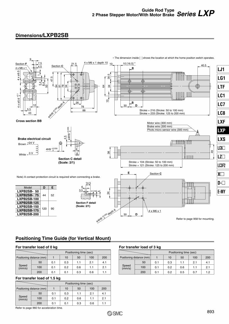
LXPB2 1BSB M9N
502.2
752.4
1002.5
1252.8
1503.0
1753.1
2003.3
5 to 40 (No condensation)3 horizontal/3 vertical Note 1)
to 200 Note 2)
±0.052 phase stepper motor (with brake)
Slide screw ø8 mm, 12 mm leadBall bushing
De-energized operating type0.1 or more24 DC ±5%
5Photo micro sensor EE-SX673
(Refer to page 1084 for details.)LC6D-220AD-� (Refer to page 963 for details.)LC6C-220AD (Refer to page 967 for details.)
Stroke
50 75100125150175200
Load (N)
42
42
40
42
32
24
17
Stroke
50 75100125150175200
Torque (N⋅m)
2.87
2.47
2.17
2.38
2.16
1.98
1.82
F
F
L
m
L
m
10
1
0.110 50 100
T
100 Auto switch types
NilM9NM9PM9BF9GF9HF9GLF9HLM9NLM9PLM9BL
D-M9ND-M9PD-M9BD-F9GD-F9HD-F9GLD-F9HLD-M9NLD-M9PLD-M9BL
Wiring/Output type
3 wire/NPN3 wire/PNP
2 wire3 wire/NPN3 wire/PNP3 wire/NPN3 wire/PNP3 wire/NPN3 wire/PNP
2 wire
0.50.50.50.50.53 3 3 3 3
Contact
N.O. (A contact)N.O. (A contact)N.O. (A contact)N.C. (B contact)N.C. (B contact)N.C. (B contact)N.C. (B contact)N.O. (A contact)N.O. (A contact)N.O. (A contact)
Without auto switch
Specifications
Performance
Main parts
Home positionswitchDriver
Positioning driver
Standard stroke (mm)Body mass (kg)Operating temperature range (°C)Work load (kg)Speed (mm/s)Positioning repeatability (mm)MotorLead screwGuide
Model
ModelModel
Electromagneticbrake
ModelStatic torque (N·m)Rated voltage (V)Power consumption (W)
This is the operating range for ball bushings.Use within the allowable thrust range.
Lifter Operation Range
50 to 200 mm stroke
Eccentric distance L (mm)
Load
mas
s m
(kg
)
125 to 200 mm stroke
50 to 100 mm stroke
Non-rotating accuracy
±0.09°
Allowable lateral load (F) Allowable plate rotation torque (T)
Plate non-rotating accuracy (θ)
Refer to page 962 for deflection data.
Operating Conditions
+θ–θ
Note 1) Based on the operating conditions, establish a separate guide when exceeding the maximum allowable lateral load.
Note 2) Since vibration may increase with low speed operation, set the driver to be driven in half-step mode, and use 12 mm/s or more as a guide for speed.
ModelSymbol Lead wirelength (m)
892
BallBushing
Slide Screw
ø 8 mm/12 mm lead
Guide Rod Type 2 Phase Stepper Motor With Motor Brake
Series LXP How to Order
Stroke (mm)Refer to the standard stroke.
NoneYes (Cable length 0.3 m)
NilS
Home position switchAuto switch type
NoneNil 1 pc.2 pcs.
6 pcs.
12
6
Number ofauto switches
… …Refer to the table on the right for auto switch part numbers.
P0878-P0909-E.qxd 10.12.15 11:50 AM Page 892
50
100
200
1
0.1
0.1
0.1
10
0.3
0.2
0.1
50
1.1
0.6
0.3
100
2.1
1.1
0.6
200
4.1
2.1
1.1
50
100
200
50
100
200
1
0.1
0.1
0.1
10
0.3
0.2
0.1
50
1.1
0.6
0.3
200
4.1
2.1
1.1
100
2.1
1.1
0.6
1
0.1
0.1
0.1
10
0.3
0.2
0.2
50
1.1
0.6
0.5
100
2.1
1.1
0.7
200
4.1
2.1
1.2
3
6
4.5
0 V
LXPB2SB- 50LXPB2SB- 75LXPB2SB-100LXPB2SB-125LXPB2SB-150LXPB2SB-175LXPB2SB-200
D
44
120
E
52
90
523.56
1
14.5
4.5
9
50
1
7.5
12
435.5
5.4
8.4
26
34789194
47.5
7888
21.5
30 D
34
E
38 49
40.5
30.5
3410
10
B
B30 D
64
4 x M6 x 1 depth 10Section C
ø4H9+0
.030
0
dept
h 6
∗ The dimension inside [ ] shows the location at which the home position switch operates.
10 [16.5] ∗
Motor wire (300 mm)
Photo micro sensor wire (300 mm)Brake wire (300 mm)
Stroke + 216 (Stroke: 50 to 100 mm)Stroke + 233 (Stroke: 125 to 200 mm)
Stroke + 104 (Stroke: 50 to 100 mm)Stroke + 121 (Stroke: 125 to 200 mm)
Refer to page 958 for mounting.
4 x M6 x 1
Section C
ø4H9+0.030
0
depth 6
ø4H
9+
0.03
0 0
4H9 +0.030 0
Section F detail(Scale: 2/1)
Note) A contact protection circuit is required when connecting a brake.
Brake electrical circuit
Brown
White
Section C detail(Scale: 2/1)
+24 V
Model
For transfer load of 0 kgPositioning time (sec)
Positioning distance (mm)
Speed(mm/s)
For transfer load of 1.5 kgPositioning time (sec)
Positioning distance (mm)
Speed(mm/s)
For transfer load of 3 kgPositioning time (sec)
Positioning distance (mm)
Speed(mm/s)
Refer to page 960 for acceleration time.
Positioning Time Guide (for Vertical Mount)
893
Dimensions/LXPB2SB
Series LXPGuide Rod Type2 Phase Stepper Motor/With Motor Brake
Cross section BB
4 x M6 x 1
4 x
ø9.
54
x ø
5.6
+0.
1 0
Section F
LJ1
LG1
LTF
LC1
LC7
LC8
LXF
LXP
LXS
LC6�
LZ�
LC3F2
X�
D-�
E-MY
P0878-P0909-E.qxd 10.12.15 11:50 AM Page 893

Body mass (kg)
Operating temperature range (°C)
Work load (kg)
Speed (mm/s)
Positioning repeatability (mm)
Motor
Lead screw
Guide
Model
Model
502.0
752.2
1002.3
1252.6
1502.8
1752.9
2003.1
5 to 40 (No condensation)
6 horizontal/5 vertical Note 1)
to 30 Note 2)
±0.03
5 phase stepper motor (without brake)
Ball screw ø8 mm, 2 mm lead
Ball bushing
Photo micro sensor EE-SX673(Refer to page 1084 for details.)
LC6D-507AD-� (Refer to page 963 details.)
Performance
Main parts
Home positionswitch
Driver
Standard stroke (mm)
LXPB5 1BC
Specifications
M9N
Operating Conditions
Stroke
50 75100125150175200
Load (N)
42
42
40
42
32
24
17
Allowable lateral load (F)Stroke
50 75100125150175200
Torque (N⋅m)
2.87
2.47
2.17
2.38
2.16
1.98
1.82
Allowable plate rotation torque (T)Non-rotating accuracy
±0.09°
Plate non-rotating accuracy (θ)
F
TF
Refer to page 962 for deflection data.
12
6
Number ofauto switches
100
None
Yes (Cable length 0.3 m)NilS
Home position switch
NoneNil
Auto switch type
Refer to the table on the right for auto switch part numbers.
1 pc.2 pcs.
6 pcs.
……
Auto switch types
NilM9NM9PM9BF9GF9HF9GLF9HLM9NLM9PLM9BL
D-M9ND-M9PD-M9BD-F9GD-F9HD-F9GLD-F9HLD-M9NLD-M9PLD-M9BL
Wiring/Output type
3 wire/NPN3 wire/PNP
2 wire3 wire/NPN3 wire/PNP3 wire/NPN3 wire/PNP3 wire/NPN3 wire/PNP
2 wire
0.50.50.50.50.53 3 3 3 3
Note 1) Based on the operating conditions, establish a separate guide when exceeding the maximum allowable lateral load.
Note 2) Since vibration may increase with low speed operation, set the driver to be driven in half-step mode, and use 2 mm/s or more as a guide for speed.
Contact
N.O. (A contact)N.O. (A contact)N.O. (A contact)N.C. (B contact)N.C. (B contact)N.C. (B contact)N.C. (B contact)N.O. (A contact)N.O. (A contact)N.O. (A contact)
Without auto switch
Made to order specifications(For details, refer to page 999)
Symbol Specifications
X20X60
Made toOrder
+θ–θ
ModelSymbol
AC servomotor specification
Low particle generation specification
Lead wirelength (m)
894
How to Order
BallBushing
Ball Screw
ø8 mm/2 mm lead
Stroke (mm)Refer to the standard stroke.
Guide Rod Type 5 Phase Stepper Motor Without Motor Brake
Series LXP
P0878-P0909-E.qxd 10.12.15 11:50 AM Page 894

For transfer load of 0 kgPositioning time (sec)
Positioning distance (mm)
Speed(mm/s)
10
20
30
1
0.2
0.1
0.1
10
1.1
0.6
0.4
50
5.1
2.6
1.7
100
10.1
5.1
3.4
200
20.1
10.1
6.7
For transfer load of 6 kgPositioning time (sec)
Positioning distance (mm)
Speed(mm/s)
10
20
30
1
0.2
0.1
0.1
10
1.1
0.6
0.4
50
5.1
2.6
1.7
200
20.1
10.1
6.7
100
10.1
5.1
3.4
For transfer load of 3 kgPositioning time (sec)
Positioning distance (mm)
Speed(mm/s)
10
20
30
1
0.2
0.1
0.1
10
1.1
0.6
0.4
50
5.1
2.6
1.7
100
10.1
5.1
3.4
200
20.1
10.1
6.7
4 x M6 x 1
Cross section BB
B
B
18
30
30.5
3464
10
10
3
6
4.5
ø4H
9+
0.03
0 0
4H9 +0.030 0
38
4.5
9
50
1
7.5
12
43
5.5
5.4
8.4
4 x
ø9.
54
x ø
5.6
+0.
1 0
49
4 x M6 x 1
Section C
30 D
34
E
ø4H9+0.030
0
depth 6
D2663
73
3478919447
.5
21.5
Refer to page 961 for acceleration time.
ModelLXPB5BC- 50LXPB5BC- 75LXPB5BC-100LXPB5BC-125LXPB5BC-150LXPB5BC-175LXPB5BC-200
D
44
120
E
52
90
523.56
1
14.5
Refer to page 958 for mounting.
4 x M6 x 1 depth 10Section C
ø4H9+0
.030
0
dept
h 6
10 [16.5] ∗
∗ The dimension inside [ ] shows the location at which the home position switch operates.
Photo micro sensor wire (300 mm)
Motor wire (300 mm)
Stroke + 181 (Stroke: 50 to 100 mm)Stroke + 198 (Stroke: 125 to 200 mm)
Stroke + 104 (Stroke: 50 to 100 mm)Stroke + 121 (Stroke: 125 to 200 mm)
Section C detail(Scale: 2/1)
Section F detail(Scale: 2/1)
895
Positioning Time Guide (for Horizontal Mount)
Dimensions/LXPB5BC
Series LXPGuide Rod Type5 Phase Stepper Motor/Without Motor Brake
Section F
LJ1
LG1
LTF
LC1
LC7
LC8
LXF
LXP
LXS
LC6�
LZ�
LC3F2
X�
D-�
E-MY
P0878-P0909-E.qxd 10.12.15 11:50 AM Page 895
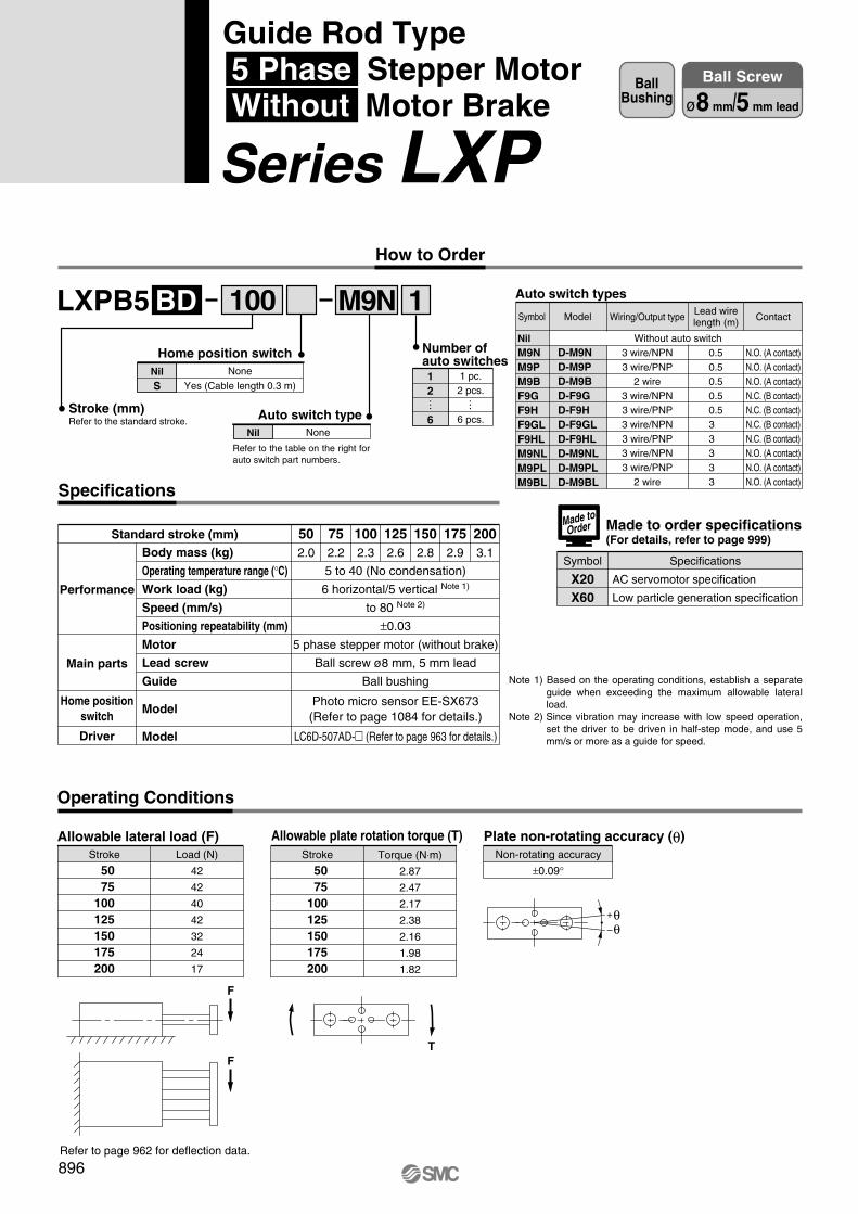
Body mass (kg)
Operating temperature range (°C)
Work load (kg)
Speed (mm/s)
Positioning repeatability (mm)
Motor
Lead screw
Guide
Model
Model
5 to 40 (No condensation)
6 horizontal/5 vertical Note 1)
to 80 Note 2)
±0.03
5 phase stepper motor (without brake)
Ball screw ø8 mm, 5 mm lead
Ball bushing
Photo micro sensor EE-SX673(Refer to page 1084 for details.)
LC6D-507AD-� (Refer to page 963 for details.)
Performance
Main parts
Home positionswitch
Driver
LXPB5 1BD
Specifications
M9N
Stroke
50 75100125150175200
Load (N)
42
42
40
42
32
24
17
Stroke
50 75100125150175200
Torque (N⋅m)
2.87
2.47
2.17
2.38
2.16
1.98
1.82
Non-rotating accuracy
±0.09°
F
TF
502.0
752.2
1002.3
1252.6
1502.8
1752.9
2003.1
100
None
Yes (Cable length 0.3 m)NilS
Home position switch
NoneNil
Auto switch type
Refer to the table on the right for auto switch part numbers.
12
6
Number ofauto switches
1 pc.2 pcs.
6 pcs.
……
Auto switch types
NilM9NM9PM9BF9GF9HF9GLF9HLM9NLM9PLM9BL
D-M9ND-M9PD-M9BD-F9GD-F9HD-F9GLD-F9HLD-M9NLD-M9PLD-M9BL
Wiring/Output type
3 wire/NPN3 wire/PNP
2 wire3 wire/NPN3 wire/PNP3 wire/NPN3 wire/PNP3 wire/NPN3 wire/PNP
2 wire
0.50.50.50.50.53 3 3 3 3
Contact
N.O. (A contact)N.O. (A contact)N.O. (A contact)N.C. (B contact)N.C. (B contact)N.C. (B contact)N.C. (B contact)N.O. (A contact)N.O. (A contact)N.O. (A contact)
Without auto switch
Made to order specifications(For details, refer to page 999)
Symbol Specifications
X20X60
Made toOrder
Standard stroke (mm)
Operating Conditions
Allowable lateral load (F) Allowable plate rotation torque (T) Plate non-rotating accuracy (θ)
Refer to page 962 for deflection data.
+θ–θ
Note 1) Based on the operating conditions, establish a separate guide when exceeding the maximum allowable lateral load.
Note 2) Since vibration may increase with low speed operation, set the driver to be driven in half-step mode, and use 5 mm/s or more as a guide for speed.
ModelSymbol
AC servomotor specification
Low particle generation specification
Lead wirelength (m)
896
BallBushing
Ball Screw
ø8 mm/5 mm lead
How to Order
Stroke (mm)Refer to the standard stroke.
Guide Rod Type 5 Phase Stepper Motor Without Motor Brake
Series LXP
P0878-P0909-E.qxd 10.12.15 11:50 AM Page 896
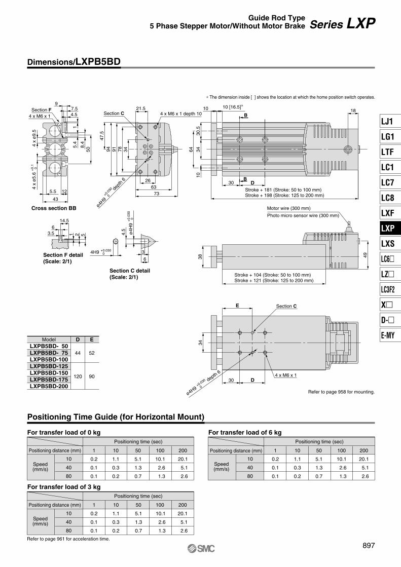
10
40
80
1
0.2
0.1
0.1
10
1.1
0.3
0.2
50
5.1
1.3
0.7
100
10.1
2.6
1.3
200
20.1
5.1
2.6
10
40
80
1
0.2
0.1
0.1
10
1.1
0.3
0.2
50
5.1
1.3
0.7
100
10.1
2.6
1.3
200
20.1
5.1
2.6
B
B
18
30
30.5
3464
10
10
3
6
4.5
38
4.5
9
50
1
7.5
12
43
5.5
5.4
8.4
49
30 D
34
E
D2663
73
3478919447
.5
21.5
ModelLXPB5BD- 50LXPB5BD- 75LXPB5BD-100LXPB5BD-125LXPB5BD-150LXPB5BD-175LXPB5BD-200
D
44
120
E
52
90
10
40
80
1
0.2
0.1
0.1
10
1.1
0.3
0.2
50
5.1
1.3
0.7
200
20.1
5.1
2.6
100
10.1
2.6
1.3
523.56
1
14.5
4 x M6 x 1 depth 10Section C
ø4H9+0
.030
0
dept
h 6
10 [16.5]∗
∗ The dimension inside [ ] shows the location at which the home position switch operates.
Stroke + 181 (Stroke: 50 to 100 mm)Stroke + 198 (Stroke: 125 to 200 mm)
Photo micro sensor wire (300 mm)
Motor wire (300 mm)
Stroke + 104 (Stroke: 50 to 100 mm)Stroke + 121 (Stroke: 125 to 200 mm)
4 x M6 x 1
Section C
ø4H9+0.030
0
depth 6
Refer to page 958 for mounting.
ø4H
9+
0.03
0 0
4H9 +0.030 0
Section C detail(Scale: 2/1)
Section F detail(Scale: 2/1)
For transfer load of 0 kgPositioning time (sec)
Positioning distance (mm)
Speed(mm/s)
For transfer load of 6 kgPositioning time (sec)
Positioning distance (mm)
Speed(mm/s)
For transfer load of 3 kgPositioning time (sec)
Positioning distance (mm)
Speed(mm/s)
Positioning Time Guide (for Horizontal Mount)
Refer to page 961 for acceleration time.
897
Dimensions/LXPB5BD
Series LXPGuide Rod Type5 Phase Stepper Motor/Without Motor Brake
4 x M6 x 1
Cross section BB
4 x
ø9.
54
x ø
5.6
+0.
1 0
Section F
LJ1
LG1
LTF
LC1
LC7
LC8
LXF
LXP
LXS
LC6�
LZ�
LC3F2
X�
D-�
E-MY
P0878-P0909-E.qxd 10.12.15 11:50 AM Page 897
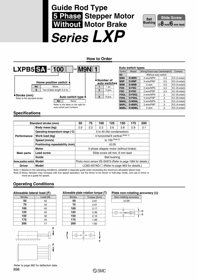
Body mass (kg)
Operating temperature range (°C)
Work load (kg)
Speed (mm/s)
Positioning repeatability (mm)
Motor
Lead screw
Guide
Model
Model
502.0
752.2
1002.3
1252.6
1502.8
1752.9
2003.1
5 to 40 (No condensation)
4 horizontal/4 vertical Note 1)
to 100 Note 2)
±0.05
5 phase stepper motor (without brake)
Slide screw ø8 mm, 6 mm lead
Ball bushing
Photo micro sensor EE-SX673 (Refer to page 1084 for details.)
LC6D-507AD-� (Refer to page 963 for details.)
Performance
Main parts
Home position switch
Driver
Standard stroke (mm)
LXPB5 1SA
Specifications
M9N
Stroke
50 75100125150175200
Load (N)
42
42
40
42
32
24
17
Stroke
50 75100125150175200
Torque (N⋅m)
2.87
2.47
2.17
2.38
2.16
1.98
1.82
F
TF
100
How to Order
Stroke (mm)Refer to the standard stroke.
None
Yes (Cable length 0.3 m)NilS
Home position switch
NoneNil
Auto switch type
Refer to the table on the right for auto switch part numbers.
12
6
Number ofauto switches
1 pc.2 pcs.
6 pcs.
……
Auto switch types
NilM9NM9PM9BF9GF9HF9GLF9HLM9NLM9PLM9BL
D-M9ND-M9PD-M9BD-F9GD-F9HD-F9GLD-F9HLD-M9NLD-M9PLD-M9BL
Model Wiring/Output type
3 wire/NPN3 wire/PNP
2 wire3 wire/NPN3 wire/PNP3 wire/NPN3 wire/PNP3 wire/NPN3 wire/PNP
2 wire
Lead wire length (m)
0.50.50.50.50.53 3 3 3 3
Contact
N.O. (A contact)N.O. (A contact)N.O. (A contact)N.C. (B contact)N.C. (B contact)N.C. (B contact)N.C. (B contact)N.O. (A contact)N.O. (A contact)N.O. (A contact)
Without auto switchSymbol
Note 1) Based on the operating conditions, establish a separate guide when exceeding the maximum allowable lateral load.Note 2) Since vibration may increase with low speed operation, set the driver to be driven in half-step mode, and use 6 mm/s or
more as a guide for speed.
Non-rotating accuracy
±0.09°
Operating Conditions
Allowable lateral load (F) Allowable plate rotation torque (T) Plate non-rotating accuracy (θ)
Refer to page 962 for deflection data.
+θ–θ
898
BallBushing
Slide Screw
ø8 mm/6 mm lead
Guide Rod Type 5 Phase Stepper Motor Without Motor Brake
Series LXP
P0878-P0909-E.qxd 10.12.15 11:50 AM Page 898
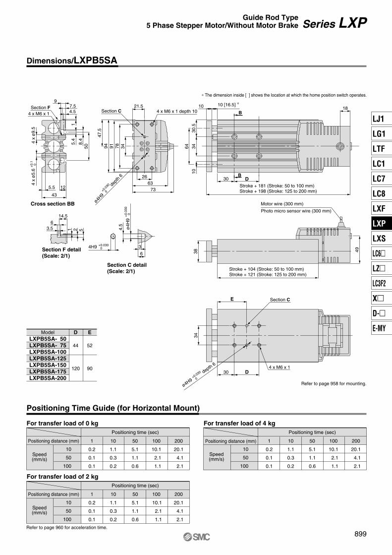
10
50
100
1
0.2
0.1
0.1
10
1.1
0.3
0.2
50
5.1
1.1
0.6
100
10.1
2.1
1.1
200
20.1
4.1
2.1
10
50
100
1
0.2
0.1
0.1
10
1.1
0.3
0.2
50
5.1
1.1
0.6
200
20.1
4.1
2.1
100
10.1
2.1
1.1
10
50
100
1
0.2
0.1
0.1
10
1.1
0.3
0.2
50
5.1
1.1
0.6
100
10.1
2.1
1.1
200
20.1
4.1
2.1
B
B
18
30
30.5
3464
10
10
3
6
4.5
38
4.5
9
50
1
7.5
12
43
5.5
5.4
8.4
49
30 D
34
E
D2663
73
3478919447
.5
21.5
ModelLXPB5SA- 50LXPB5SA- 75LXPB5SA-100LXPB5SA-125LXPB5SA-150LXPB5SA-175LXPB5SA-200
D
44
120
E
52
90
523.56
1
14.5
4 x M6 x 1 depth 10Section C
ø4H9+0
.030
0
dept
h 6
10 [16.5] ∗
∗ The dimension inside [ ] shows the location at which the home position switch operates.
Stroke + 181 (Stroke: 50 to 100 mm)Stroke + 198 (Stroke: 125 to 200 mm)
Photo micro sensor wire (300 mm)
Motor wire (300 mm)
Stroke + 104 (Stroke: 50 to 100 mm)Stroke + 121 (Stroke: 125 to 200 mm)
4 x M6 x 1
Section C
ø4H9+0.030
0
depth 6
Refer to page 958 for mounting.
Section C detail(Scale: 2/1)
Section F detail(Scale: 2/1)
ø4H
9+
0.03
0 0
4H9 +0.030 0
For transfer load of 0 kgPositioning time (sec)
Positioning distance (mm)
Speed(mm/s)
For transfer load of 4 kgPositioning time (sec)
Positioning distance (mm)
Speed(mm/s)
For transfer load of 2 kgPositioning time (sec)
Positioning distance (mm)
Speed(mm/s)
Positioning Time Guide (for Horizontal Mount)
Refer to page 960 for acceleration time.
899
Dimensions/LXPB5SA
Series LXPGuide Rod Type5 Phase Stepper Motor/Without Motor Brake
4 x M6 x 1
Cross section BB
4 x
ø9.
54
x ø
5.6
+0.
1 0
Section F
LJ1
LG1
LTF
LC1
LC7
LC8
LXF
LXP
LXS
LC6�
LZ�
LC3F2
X�
D-�
E-MY
P0878-P0909-E.qxd 10.12.15 11:50 AM Page 899

Body mass (kg)
Operating temperature range (°C)
Work load (kg)
Speed (mm/s)
Positioning repeatability (mm)
Motor
Lead screw
Guide
Model
Model
502.0
752.2
1002.3
1252.6
1502.8
1752.9
2003.1
5 to 40 (No condensation)
2 horizontal/2 vertical Note 1)
to 200 Note 2)
±0.05
5 phase stepper motor (without brake)
Slide screw ø8 mm, 12 mm lead
Ball bushing
Photo micro sensor EE-SX673 (Refer to page 1084 for details.)
LC6D-507AD-� (Refer to page 963 for details.)
Performance
Main parts
Home position switch
Driver
LXPB5 1SB
Specifications
M9N
Stroke
50 75100125150175200
Load (N)
42
42
40
42
32
24
17
Stroke
50 75100125150175200
Torque (N⋅m)
2.87
2.47
2.17
2.38
2.16
1.98
1.82
F
TF
100 Auto switch types
NilM9NM9PM9BF9GF9HF9GLF9HLM9NLM9PLM9BL
D-M9ND-M9PD-M9BD-F9GD-F9HD-F9GLD-F9HLD-M9NLD-M9PLD-M9BL
Model Wiring/Output type
3 wire/NPN3 wire/PNP
2 wire3 wire/NPN3 wire/PNP3 wire/NPN3 wire/PNP3 wire/NPN3 wire/PNP
2 wire
Lead wire length (m)
0.50.50.50.50.53 3 3 3 3
Contact
N.O. (A contact)N.O. (A contact)N.O. (A contact)N.C. (B contact)N.C. (B contact)N.C. (B contact)N.C. (B contact)N.O. (A contact)N.O. (A contact)N.O. (A contact)
Without auto switchSymbol
Standard stroke (mm)
Note 1) Based on the operating conditions, establish a separate guide when exceeding the maximum allowable lateral load.Note 2) Since vibration may increase with low speed operation, set the driver to be driven in half-step mode, and use 12 mm/s or
more as a guide for speed.
Non-rotating accuracy
±0.09°
Operating Conditions
Allowable lateral load (F) Allowable plate rotation torque (T) Plate non-rotating accuracy (θ)
Refer to page 962 for deflection data.
+θ–θ
900
BallBushing
Slide Screw
ø8 mm/12 mm lead
How to Order
Stroke (mm)Refer to the standard stroke.
None
Yes (Cable length 0.3 m)NilS
Home position switch
NoneNil
Auto switch type
Refer to the table on the right for auto switch part numbers.
12
6
Number ofauto switches
1 pc.2 pcs.
6 pcs.
……
Guide Rod Type 5 Phase Stepper Motor Without Motor Brake
Series LXP
P0878-P0909-E.qxd 10.12.15 11:50 AM Page 900

50
100
200
1
0.1
0.1
0.1
10
0.3
0.2
0.1
50
1.1
0.6
0.3
100
2.1
1.1
0.6
200
4.1
2.1
1.1
50
100
200
1
0.1
0.1
0.1
10
0.3
0.2
0.1
50
1.1
0.6
0.3
200
4.1
2.1
1.1
100
2.1
1.1
0.6
50
100
200
1
0.1
0.1
0.1
10
0.3
0.2
0.1
50
1.1
0.6
0.3
100
2.1
1.1
0.6
200
4.1
2.1
1.1
B
B
18
30
30.5
3464
10
10
3
6
4.5
38
4.5
9
50
1
7.5
12
43
5.5
5.4
8.4
49
30 D
34
E
D2663
73
3478919447
.5
21.5
LXPB5SB- 50LXPB5SB- 75LXPB5SB-100LXPB5SB-125LXPB5SB-150LXPB5SB-175LXPB5SB-200
D
44
120
E
52
90
523.56
1
14.5
4 x M6 x 1 depth 10Section C
ø4H9+0
.030
0
dept
h 6
10 [16.5] ∗
∗ The dimension inside [ ] shows the location at which the home position switch operates.
Stroke + 181 (Stroke: 50 to 100 mm)Stroke + 198 (Stroke: 125 to 200 mm)
Photo micro sensor wire (300 mm)
Motor wire (300 mm)
Stroke + 104 (Stroke: 50 to 100 mm)Stroke + 121 (Stroke: 125 to 200 mm)
4 x M6 x 1
Section C
ø4H9+0.030
0
depth 6
Refer to page 958 for mounting.
Section C detail(Scale: 2/1)
Section F detail(Scale: 2/1)
ø4H
9+
0.03
0 0
4H9 +0.030 0
Model
For transfer load of 0 kgPositioning time (sec)
Positioning distance (mm)
Speed(mm/s)
For transfer load of 2 kgPositioning time (sec)
Positioning distance (mm)
Speed(mm/s)
For transfer load of 1 kgPositioning time (sec)
Positioning distance (mm)
Speed(mm/s)
Positioning Time Guide (for Horizontal Mount)
Refer to page 960 for acceleration time.
901
Dimensions/LXPB5SB
Series LXPGuide Rod Type5 Phase Stepper Motor/Without Motor Brake
4 x M6 x 1
Cross section BB
4 x
ø9.
54
x ø
5.6
+0.
1 0
Section F
LJ1
LG1
LTF
LC1
LC7
LC8
LXF
LXP
LXS
LC6�
LZ�
LC3F2
X�
D-�
E-MY
P0878-P0909-E.qxd 10.12.15 11:50 AM Page 901
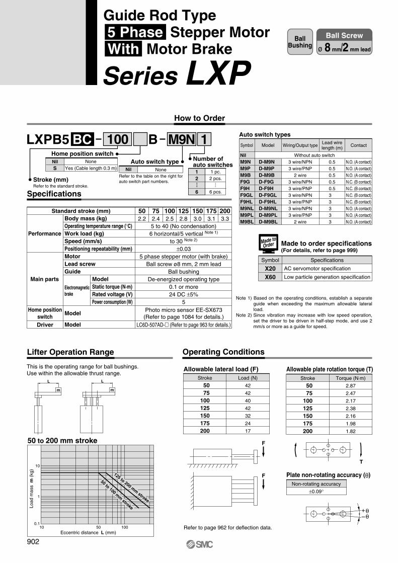
LXPB5 1BBC M9N
Body mass (kg)Operating temperature range (°C)Work load (kg)Speed (mm/s)Positioning repeatability (mm)MotorLead screwGuide
Model
Model
502.2
752.4
1002.5
1252.8
1503.0
1753.1
2003.3
5 to 40 (No condensation)6 horizontal/5 vertical Note 1)
to 30 Note 2)
±0.035 phase stepper motor (with brake)
Ball screw ø8 mm, 2 mm leadBall bushing
De-energized operating type0.1 or more24 DC ±5%
5Photo micro sensor EE-SX673
(Refer to page 1084 for details.)LC6D-507AD-� (Refer to page 963 for details.)
Performance
Main parts
Home positionswitchDriver
Standard stroke (mm)
Electromagneticbrake
ModelStatic torque (N·m)Rated voltage (V)Power consumption (W)
Stroke
50 75100125150175200
Load (N)
42
42
40
42
32
24
17
Allowable lateral load (F)Stroke
50 75100125150175200
Torque (N⋅m)
2.87
2.47
2.17
2.38
2.16
1.98
1.82
Allowable plate rotation torque (T)
Non-rotating accuracy
±0.09°
Plate non-rotating accuracy (θ)
F
F
This is the operating range for ball bushings.Use within the allowable thrust range.
L
m
L
m
50 to 200 mm stroke
10
1
0.110 50 100
Eccentric distance L (mm)
Load
mas
s m
(kg
)
125 to 200 mm stroke
50 to 100 mm stroke
T
Refer to page 962 for deflection data.
Lifter Operation Range Operating Conditions
Specifications
100 Auto switch types
NilM9NM9PM9BF9GF9HF9GLF9HLM9NLM9PLM9BL
D-M9ND-M9PD-M9BD-F9GD-F9HD-F9GLD-F9HLD-M9NLD-M9PLD-M9BL
Wiring/Output type
3 wire/NPN3 wire/PNP
2 wire3 wire/NPN3 wire/PNP3 wire/NPN3 wire/PNP3 wire/NPN3 wire/PNP
2 wire
0.50.50.50.50.53 3 3 3 3
Contact
N.O. (A contact)N.O. (A contact)N.O. (A contact)N.C. (B contact)N.C. (B contact)N.C. (B contact)N.C. (B contact)N.O. (A contact)N.O. (A contact)N.O. (A contact)
Without auto switch
Made to order specifications(For details, refer to page 999)
Symbol Specifications
X20X60
Made toOrder
+θ–θ
ModelSymbol
AC servomotor specification
Low particle generation specification
Lead wirelength (m)
Note 1) Based on the operating conditions, establish a separate guide when exceeding the maximum allowable lateral load.
Note 2) Since vibration may increase with low speed operation, set the driver to be driven in half-step mode, and use 2 mm/s or more as a guide for speed.
902
BallBushing
Ball Screw
ø 8 mm/2 mm lead
How to Order
Stroke (mm)Refer to the standard stroke.
NoneYes (Cable length 0.3 m)
NilS
Home position switchAuto switch type
NoneNil 1 pc.2 pcs.
6 pcs.
12
6
Number ofauto switches
… …Refer to the table on the right for auto switch part numbers.
Guide Rod Type 5 Phase Stepper Motor With Motor Brake
Series LXP
P0878-P0909-E.qxd 10.12.15 11:50 AM Page 902

For transfer load of 0 kgPositioning time (sec)
Positioning distance (mm)
Speed(mm/s)
10
20
30
For transfer load of 5 kgPositioning time (sec)
Positioning distance (mm)
Speed(mm/s)
10
20
30
1
0.2
0.1
0.1
Refer to page 961 for acceleration time.
10
1.1
0.6
0.4
50
5.1
2.6
1.7
200
20.1
10.1
6.7
100
10.1
5.1
3.4
1
0.2
0.1
0.1
10
1.1
0.6
0.4
50
5.1
2.6
1.7
200
20.1
10.1
6.7
100
10.1
5.1
3.4
For transfer load of 2.5 kgPositioning time (sec)
Positioning distance (mm)
Speed(mm/s)
10
20
30
1
0.2
0.1
0.1
10
1.1
0.6
0.4
50
5.1
2.6
1.7
200
20.1
10.1
6.7
100
10.1
5.1
3.4
3
6
4.5
ø4H
9+
0.03
0 0
4H9 +0.030 0
Section C detail(Scale: 2/1)
Brake electrical circuit+24 V
0 V
Note) A contact protection circuit is required when connecting a brake.
Brown
White
∗ The dimension inside [ ] shows the location at which the home position switch operates.
ModelLXPB5BC- 50�BLXPB5BC- 75�BLXPB5BC-100�BLXPB5BC-125�BLXPB5BC-150�BLXPB5BC-175�BLXPB5BC-200�B
D
44
120
E
52
90
Refer to page 958 for mounting.
Section F detail(Scale: 2/1)
523.56
1
14.5
4.5
9
50
1
7.5
12
435.5
5.4
8.4
26
34789194
47.5
7888
21.5
4 x M6 x 1
Section C
30 D
34
E
ø4H9+0.030
0
depth 6
38 49
40.5
30.5
3410
10
B
B30 D
64
4 x M6 x 1 depth 10Section C
ø4H9+0
.030
0
dept
h 6
10 [16.5] ∗
Stroke + 216 (Stroke: 50 to 100 mm)Stroke + 233 (Stroke: 125 to 200 mm)
Motor wire (300 mm)
Photo micro sensor wire (300 mm)Brake wire (300 mm)
Stroke + 104 (Stroke: 50 to 100 mm)Stroke + 121 (Stroke: 125 to 200 mm)
903
Dimensions/LXPB5BC
Positioning Time Guide (for Vertical Mount)
Series LXPGuide Rod Type5 Phase Stepper Motor/With Motor Brake
4 x M6 x 1
Cross section BB
4 x
ø9.
54
x ø
5.6
+0.
1 0
Section F
LJ1
LG1
LTF
LC1
LC7
LC8
LXF
LXP
LXS
LC6�
LZ�
LC3F2
X�
D-�
E-MY
P0878-P0909-E.qxd 10.12.15 11:50 AM Page 903
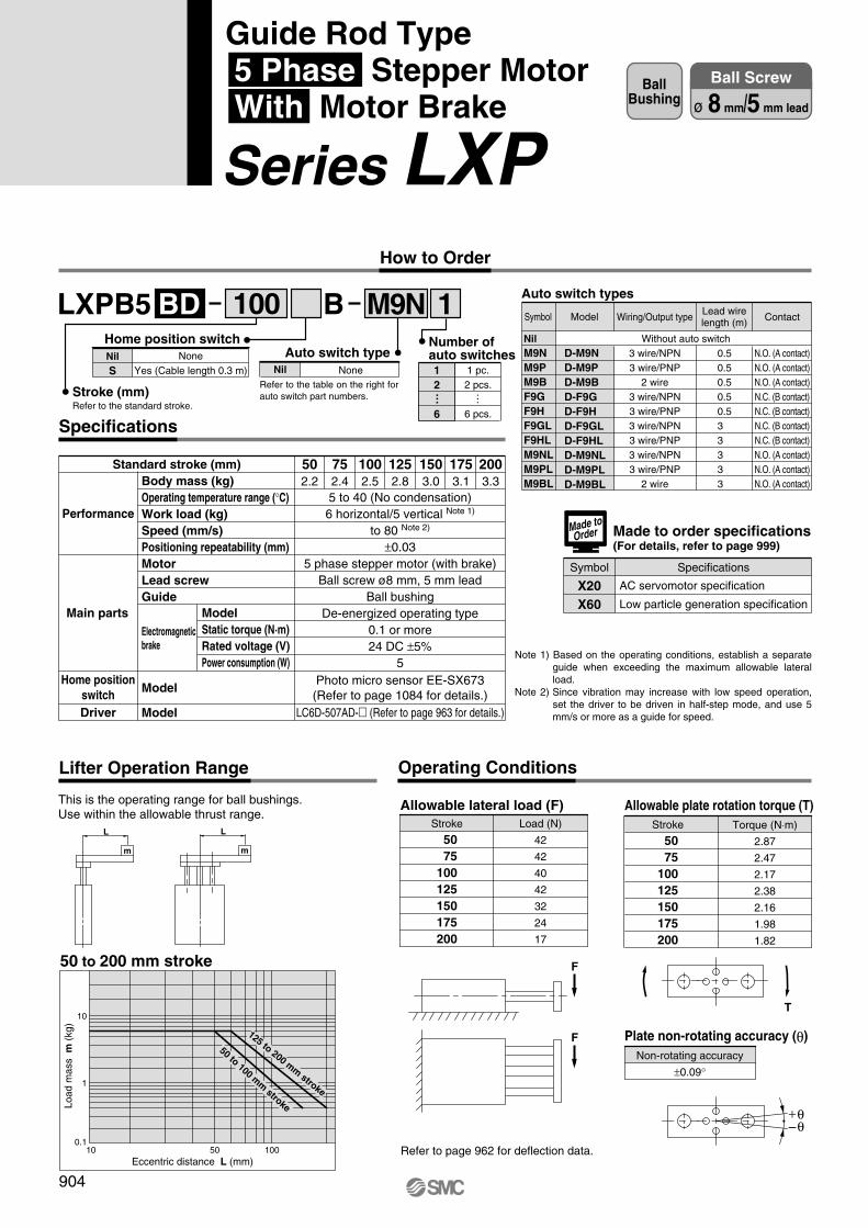
LXPB5 1BBD M9N
Body mass (kg)Operating temperature range (°C)Work load (kg)Speed (mm/s)Positioning repeatability (mm)MotorLead screwGuide
Model
Model
502.2
752.4
1002.5
1252.8
1503.0
1753.1
2003.3
5 to 40 (No condensation)6 horizontal/5 vertical Note 1)
to 80 Note 2)
±0.035 phase stepper motor (with brake)
Ball screw ø8 mm, 5 mm leadBall bushing
De-energized operating type0.1 or more24 DC ±5%
5Photo micro sensor EE-SX673
(Refer to page 1084 for details.)LC6D-507AD-� (Refer to page 963 for details.)
Performance
Main parts
Home positionswitchDriver
Electromagneticbrake
ModelStatic torque (N·m)Rated voltage (V)Power consumption (W)
Stroke
50 75100125150175200
Load (N)
42
42
40
42
32
24
17
Stroke
50 75100125150175200
Torque (N⋅m)
2.87
2.47
2.17
2.38
2.16
1.98
1.82
F
F
L
m
L
m
10
1
0.110 50 100
T
Specifications
100 Auto switch types
NilM9NM9PM9BF9GF9HF9GLF9HLM9NLM9PLM9BL
D-M9ND-M9PD-M9BD-F9GD-F9HD-F9GLD-F9HLD-M9NLD-M9PLD-M9BL
Wiring/Output type
3 wire/NPN3 wire/PNP
2 wire3 wire/NPN3 wire/PNP3 wire/NPN3 wire/PNP3 wire/NPN3 wire/PNP
2 wire
0.50.50.50.50.53 3 3 3 3
Contact
N.O. (A contact)N.O. (A contact)N.O. (A contact)N.C. (B contact)N.C. (B contact)N.C. (B contact)N.C. (B contact)N.O. (A contact)N.O. (A contact)N.O. (A contact)
Without auto switch
Made to order specifications(For details, refer to page 999)
Symbol Specifications
X20X60
Made toOrder
Standard stroke (mm)
This is the operating range for ball bushings.Use within the allowable thrust range.
50 to 200 mm stroke
Eccentric distance L (mm)
Load
mas
s m
(kg
)
125 to 200 mm stroke
50 to 100 mm stroke
Lifter Operation Range
Allowable lateral load (F) Allowable plate rotation torque (T)
Non-rotating accuracy
±0.09°
Plate non-rotating accuracy (θ)
Refer to page 962 for deflection data.
Operating Conditions
+θ–θ
ModelSymbol
AC servomotor specification
Low particle generation specification
Lead wirelength (m)
Note 1) Based on the operating conditions, establish a separate guide when exceeding the maximum allowable lateral load.
Note 2) Since vibration may increase with low speed operation, set the driver to be driven in half-step mode, and use 5 mm/s or more as a guide for speed.
904
BallBushing
Ball Screw
ø 8 mm/5 mm lead
How to Order
Stroke (mm)Refer to the standard stroke.
NoneYes (Cable length 0.3 m)
NilS
Home position switchAuto switch type
NoneNil 1 pc.2 pcs.
6 pcs.
12
6
Number ofauto switches
… …Refer to the table on the right for auto switch part numbers.
Guide Rod Type 5 Phase Stepper Motor With Motor Brake
Series LXP
P0878-P0909-E.qxd 10.12.15 11:50 AM Page 904

10
40
80
10
40
80
1
0.2
0.1
0.1
10
1.1
0.3
0.2
50
5.1
1.3
0.7
200
20.1
5.1
2.6
100
10.1
2.6
1.3
1
0.2
0.1
0.1
10
1.1
0.3
0.2
50
5.1
1.3
0.7
200
20.1
5.1
2.6
100
10.1
2.6
1.3
10
40
80
1
0.2
0.1
0.1
10
1.1
0.3
0.2
50
5.1
1.3
0.7
200
20.1
5.1
2.6
100
10.1
2.6
1.3
3
6
4.5
Note) A contact protection circuit is required when connecting a brake.
ModelLXPB5BD- 50�BLXPB5BD- 75�BLXPB5BD-100�BLXPB5BD-125�BLXPB5BD-150�BLXPB5BD-175�BLXPB5BD-200�B
D
44
120
E
52
90Section F detail(Scale: 2/1)
523.56
1
14.5
4.5
9
50
1
7.5
12
435.5
5.4
8.4
26
34789194
47.5
7888
21.5
30 D
34
E
38 49
40.5
30.5
3410
10
B
B30 D
64
4 x M6 x 1 depth 10Section C
ø4H9+0
.030
0
dept
h 6
∗ The dimension inside [ ] shows the location at which the home position switch operates.
10 [16.5] ∗
Stroke + 216 (Stroke: 50 to 100 mm)Stroke + 233 (Stroke: 125 to 200 mm)
Motor wire (300 mm)
Photo micro sensor wire (300 mm)Brake wire (300 mm)
Refer to page 958 for mounting.
4 x M6 x 1
Section C
ø4H9+0.030
0
depth 6
Stroke + 104 (Stroke: 50 to 100 mm)Stroke + 121 (Stroke: 125 to 200 mm)
ø4H
9+
0.03
0 0
4H9 +0.030 0
Section C detail(Scale: 2/1)
Brake electrical circuit+24 V
0 V
Brown
White
For transfer load of 0 kgPositioning time (sec)
Positioning distance (mm)
Speed(mm/s)
For transfer load of 5 kgPositioning time (sec)
Positioning distance (mm)
Speed(mm/s)
Refer to page 961 for acceleration time.
For transfer load of 2.5 kgPositioning time (sec)
Positioning distance (mm)
Speed(mm/s)
Positioning Time Guide (for Vertical Mount)
905
Dimensions/LXPB5BD
Series LXPGuide Rod Type5 Phase Stepper Motor/With Motor Brake
4 x M6 x 1
Cross section BB
4 x
ø9.
54
x ø
5.6
+0.
1 0
Section F
LJ1
LG1
LTF
LC1
LC7
LC8
LXF
LXP
LXS
LC6�
LZ�
LC3F2
X�
D-�
E-MY
P0878-P0909-E.qxd 10.12.15 11:50 AM Page 905

LXPB5 1BSA M9N
Body mass (kg)Operating temperature range (°C)Work load (kg)Speed (mm/s)Positioning repeatability (mm)MotorLead screwGuide
Model
Model
502.2
752.4
1002.5
1252.8
1503.0
1753.1
2003.3
5 to 40 (No condensation)4 horizontal/4 vertical Note 1)
to 100 Note 2)
±0.055 phase stepper motor (with brake)
Slide screw ø8 mm, 6 mm leadBall bushing
De-energized operating type0.1 or more24 DC ±5%
5Photo micro sensor EE-SX673
(Refer to page 1084 for details.)LC6D-507AD-� (Refer to page 963 for details.)
Performance
Main parts
Home positionswitchDriver
Standard stroke (mm)
Electromagneticbrake
ModelStatic torque (N·m)Rated voltage (V)Power consumption (W)
Stroke
50 75100125150175200
Load (N)
42
42
40
42
32
24
17
Stroke
50 75100125150175200
Torque (N⋅m)
2.87
2.47
2.17
2.38
2.16
1.98
1.82
F
F
L
m
L
m
10
1
0.110 50 100
T
Specifications
100None
Yes (Cable length 0.3 m)NilS
Home position switchAuto switch type
NoneNil 1 pc.2 pcs.
6 pcs.
12
6
Number ofauto switches
… …
Auto switch types
NilM9NM9PM9BF9GF9HF9GLF9HLM9NLM9PLM9BL
D-M9ND-M9PD-M9BD-F9GD-F9HD-F9GLD-F9HLD-M9NLD-M9PLD-M9BL
Wiring/Output type
3 wire/NPN3 wire/PNP
2 wire3 wire/NPN3 wire/PNP3 wire/NPN3 wire/PNP3 wire/NPN3 wire/PNP
2 wire
0.50.50.50.50.53 3 3 3 3
Contact
N.O. (A contact)N.O. (A contact)N.O. (A contact)N.C. (B contact)N.C. (B contact)N.C. (B contact)N.C. (B contact)N.O. (A contact)N.O. (A contact)N.O. (A contact)
Without auto switch
Note 1) Based on the operating conditions, establish a separate guide when exceeding the maximum allowable lateral load.
Note 2) Since vibration may increase with low speed operation, set the driver to be driven in half-step mode, and use 6 mm/s or more as a guide for speed.
This is the operating range for ball bushings.Use within the allowable thrust range.
50 to 200 mm stroke
Eccentric distance L (mm)
Load
mas
s m
(kg
)
125 to 200 mm stroke
50 to 100 mm stroke
Lifter Operation Range
Allowable lateral load (F) Allowable plate rotation torque (T)
Non-rotating accuracy
±0.09°
Plate non-rotating accuracy (θ)
Refer to page 962 for deflection data.
Operating Conditions
+θ–θ
ModelSymbol Lead wirelength (m)
906
BallBushing
Slide Screw
ø 8 mm/6 mm lead
How to Order
Stroke (mm)Refer to the standard stroke.
Refer to the table on the right for auto switch part numbers.
Guide Rod Type 5 Phase Stepper Motor With Motor Brake
Series LXP
P0878-P0909-E.qxd 10.12.15 11:50 AM Page 906

10
50
100
10
50
100
1
0.2
0.1
0.1
10
1.1
0.3
0.3
50
5.1
1.1
0.7
200
20.1
4.1
2.2
100
10.1
2.1
1.2
1
0.2
0.1
0.1
10
1.1
0.3
0.2
50
5.1
1.1
0.6
200
20.1
4.1
2.1
100
10.1
2.1
1.1
10
50
100
1
0.2
0.1
0.1
10
1.1
0.3
0.2
50
5.1
1.1
0.6
200
20.1
4.1
2.1
100
10.1
2.1
1.1
3
6
4.5
ModelLXPB5SA- 50�BLXPB5SA- 75�BLXPB5SA-100�BLXPB5SA-125�BLXPB5SA-150�BLXPB5SA-175�BLXPB5SA-200�B
D
44
120
E
52
90
523.56
1
14.5
4.5
9
50
1
7.5
12
435.5
5.4
8.4
26
34789194
47.5
7888
21.5
30 D
34
E
38 49
40.5
30.5
3410
10
B
B30 D
64
4 x M6 x 1 depth 10Section C
ø4H9+0
.030
0
dept
h 6
∗ The dimension inside [ ] shows the location at which the home position switch operates.
10 [16.5] ∗
Stroke + 216 (Stroke: 50 to 100 mm)Stroke + 233 (Stroke: 125 to 200 mm)
Motor wire (300 mm)
Photo micro sensor wire (300 mm)Brake wire (300 mm)
Refer to page 958 for mounting.
4 x M6 x 1
Section C
ø4H9+0.030
0
depth 6
Stroke + 104 (Stroke: 50 to 100 mm)Stroke + 121 (Stroke: 125 to 200 mm)
ø4H
9+
0.03
0 0
4H9 +0.030 0
Section C detail(Scale: 2/1)
Brake electrical circuit+24 V
0 V
Brown
White
Note) A contact protection circuit is required when connecting a brake.
Section F detail(Scale: 2/1)
For transfer load of 0 kgPositioning time (sec)
Positioning distance (mm)
Speed(mm/s)
For transfer load of 4 kgPositioning time (sec)
Positioning distance (mm)
Speed(mm/s)
Refer to page 960 for acceleration time.
For transfer load of 2 kgPositioning time (sec)
Positioning distance (mm)
Speed(mm/s)
Positioning Time Guide (for Vertical Mount)
907
Dimensions/LXPB5SA
Series LXPGuide Rod Type5 Phase Stepper Motor/With Motor Brake
4 x M6 x 1
Cross section BB
4 x
ø9.
54
x ø
5.6
+0.
1 0
Section F
LJ1
LG1
LTF
LC1
LC7
LC8
LXF
LXP
LXS
LC6�
LZ�
LC3F2
X�
D-�
E-MY
P0878-P0909-E.qxd 10.12.15 11:50 AM Page 907
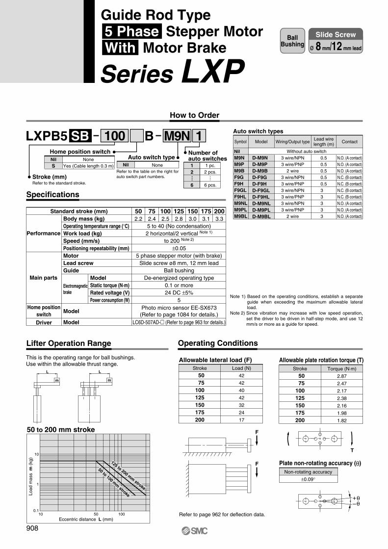
LXPB5 1BSB M9N
Body mass (kg)Operating temperature range (°C)Work load (kg)Speed (mm/s)Positioning repeatability (mm)MotorLead screwGuide
Model
Model
502.2
752.4
1002.5
1252.8
1503.0
1753.1
2003.3
5 to 40 (No condensation)2 horizontal/2 vertical Note 1)
to 200 Note 2)
±0.055 phase stepper motor (with brake)
Slide screw ø8 mm, 12 mm leadBall bushing
De-energized operating type0.1 or more24 DC ±5%
5Photo micro sensor EE-SX673
(Refer to page 1084 for details.)LC6D-507AD-� (Refer to page 963 for details.)
Performance
Main parts
Home positionswitchDriver
Electromagneticbrake
ModelStatic torque (N·m)Rated voltage (V)Power consumption (W)
Stroke
50 75100125150175200
Load (N)
42
42
40
42
32
24
17
Stroke
50 75100125150175200
Torque (N⋅m)
2.87
2.47
2.17
2.38
2.16
1.98
1.82
F
F
L
m
L
m
10
1
0.110 50 100
T
Specifications
100 Auto switch types
NilM9NM9PM9BF9GF9HF9GLF9HLM9NLM9PLM9BL
D-M9ND-M9PD-M9BD-F9GD-F9HD-F9GLD-F9HLD-M9NLD-M9PLD-M9BL
Wiring/Output type
3 wire/NPN3 wire/PNP
2 wire3 wire/NPN3 wire/PNP3 wire/NPN3 wire/PNP3 wire/NPN3 wire/PNP
2 wire
0.50.50.50.50.53 3 3 3 3
ModelSymbol Lead wirelength (m) Contact
N.O. (A contact)N.O. (A contact)N.O. (A contact)N.C. (B contact)N.C. (B contact)N.C. (B contact)N.C. (B contact)N.O. (A contact)N.O. (A contact)N.O. (A contact)
Without auto switch
Standard stroke (mm)
Note 1) Based on the operating conditions, establish a separate guide when exceeding the maximum allowable lateral load.
Note 2) Since vibration may increase with low speed operation, set the driver to be driven in half-step mode, and use 12 mm/s or more as a guide for speed.
This is the operating range for ball bushings.Use within the allowable thrust range.
50 to 200 mm stroke
Eccentric distance L (mm)
Load
mas
s m
(kg
)
125 to 200 mm stroke
50 to 100 mm stroke
Lifter Operation Range
Allowable lateral load (F) Allowable plate rotation torque (T)
Non-rotating accuracy
±0.09°
Plate non-rotating accuracy (θ)
Refer to page 962 for deflection data.
Operating Conditions
+θ–θ
908
BallBushing
Slide Screw
ø 8 mm/12 mm lead
How to Order
NoneYes (Cable length 0.3 m)
NilS
Home position switch
Stroke (mm)Refer to the standard stroke.
Auto switch typeNoneNil 1 pc.
2 pcs.
6 pcs.
12
6
Number ofauto switches
… …Refer to the table on the right for auto switch part numbers.
Guide Rod Type 5 Phase Stepper Motor With Motor Brake
Series LXP
P0878-P0909-E.qxd 10.12.15 11:50 AM Page 908
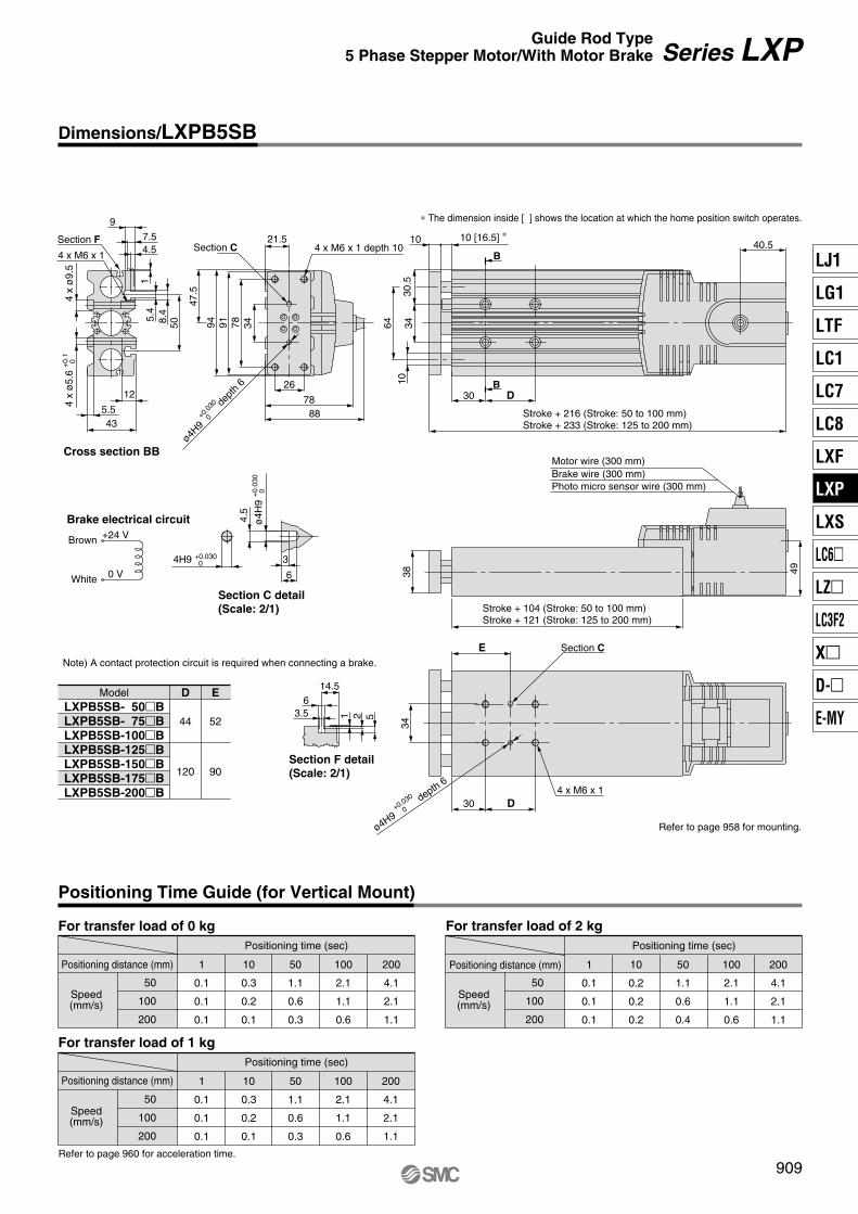
4.5
9
50
1
7.5
12
435.5
5.4
8.4
26
34789194
47.5
7888
21.5
30 D
34
E
38 49
40.5
30.5
3410
10
B
B30 D
64
50
100
200
50
100
200
1
0.1
0.1
0.1
10
0.2
0.2
0.2
50
1.1
0.6
0.4
200
4.1
2.1
1.1
100
2.1
1.1
0.6
1
0.1
0.1
0.1
10
0.3
0.2
0.1
50
1.1
0.6
0.3
200
4.1
2.1
1.1
100
2.1
1.1
0.6
50
100
200
1
0.1
0.1
0.1
10
0.3
0.2
0.1
50
1.1
0.6
0.3
200
4.1
2.1
1.1
100
2.1
1.1
0.6
3
6
4.5
LXPB5SB- 50�BLXPB5SB- 75�BLXPB5SB-100�BLXPB5SB-125�BLXPB5SB-150�BLXPB5SB-175�BLXPB5SB-200�B
D
44
120
E
52
90
523.56
1
14.5
4 x M6 x 1 depth 10Section C
ø4H9+0
.030
0
dept
h 6
4 x M6 x 1
Cross section BB
4 x
ø9.
54
x ø
5.6
+0.
1 0
Section F
∗ The dimension inside [ ] shows the location at which the home position switch operates.
10 [16.5] ∗
Stroke + 216 (Stroke: 50 to 100 mm)Stroke + 233 (Stroke: 125 to 200 mm)
Motor wire (300 mm)
Photo micro sensor wire (300 mm)Brake wire (300 mm)
Refer to page 958 for mounting.
4 x M6 x 1
Section C
ø4H9+0.030
0
depth 6
Stroke + 104 (Stroke: 50 to 100 mm)Stroke + 121 (Stroke: 125 to 200 mm)
ø4H
9+
0.03
0 0
4H9 +0.030 0
Section C detail(Scale: 2/1)
Brake electrical circuit+24 V
0 V
Brown
White
Model
Note) A contact protection circuit is required when connecting a brake.
Section F detail(Scale: 2/1)
For transfer load of 0 kgPositioning time (sec)
Positioning distance (mm)
Speed(mm/s)
For transfer load of 2 kgPositioning time (sec)
Positioning distance (mm)
Speed(mm/s)
Refer to page 960 for acceleration time.
For transfer load of 1 kgPositioning time (sec)
Positioning distance (mm)
Speed(mm/s)
Positioning Time Guide (for Vertical Mount)
909
Dimensions/LXPB5SB
Series LXPGuide Rod Type5 Phase Stepper Motor/With Motor Brake
LJ1
LG1
LTF
LC1
LC7
LC8
LXF
LXP
LXS
LC6�
LZ�
LC3F2
X�
D-�
E-MY
P0878-P0909-E.qxd 10.12.15 11:50 AM Page 909

LXSH2 1BC
Allowable Moment (N·m)
Allowable static moment Allowable dynamic moment
Refer to page 962 for deflection data.
LXSModelLoadmovement direction
Pitc
hing
Rol
ling
Yaw
ing
Transfer load m (kg)
Transfer load m (kg)
Transfer load m (kg)
L1
(mm
)L
2 (m
m)
L2
(mm
)
2000
1000
5 100
5 100
5 100
500
1000
500
1000
a = 1000
a = 2000a = 3000
a = 1000 to 3000
a = 1000 to 3000
aMep
L2
Mer
L2
Mey
L1
m
m
m
a
M9N Auto switch types
NilM9NM9PM9BF9GF9HF9GLF9HLM9NLM9PLM9BL
D-M9ND-M9PD-M9BD-F9GD-F9HD-F9GLD-F9HLD-M9NLD-M9PLD-M9BL
Model Wiring/Output type
3 wire/NPN3 wire/PNP
2 wire3 wire/NPN3 wire/PNP3 wire/NPN3 wire/PNP3 wire/NPN3 wire/PNP
2 wire
Lead wire length (m)
0.50.50.50.50.53 3 3 3 3
Contact
N.O. (A contact)N.O. (A contact)N.O. (A contact)N.C. (B contact)N.C. (B contact)N.C. (B contact)N.C. (B contact)N.O. (A contact)N.O. (A contact)N.O. (A contact)
Proximity switch typesSymbol
GGDGBGDBGUGUB
GN
GX-F8AGX-F8AIGX-F8BGX-F8BIGXL-8FUGXL-8FUB
Model Wiring/Output type
3 wire/NPN3 wire/NPN3 wire/NPN3 wire/NPN
2 wire/solid state2 wire/solid state
Lead wire length (m)
111111
Contact
——————
N.O. (A contact)N.O. (A contact)N.C. (B contact)N.C. (B contact)N.O. (A contact)N.C. (B contact)
∗ Refer to page 1082 for detailed specifications of proximity switches.
Without auto switch
High RigidityDirect Acting
Guide
100Stroke (mm)Refer to the standard stroke.
Ball Screw
ø8 mm/2 mm lead
NoneYes (Cable length 0.3 m)
NilS
Home position switch
NoneNil
Auto/Proximity switch type
Refer to the table on the right for auto/prox-imity switch part numbers.
Symbol
Specifications
Body mass (kg)Operating temperature range (°C)
Work load (kg)
Speed (mm/s)Positioning repeatability (mm)
Motor
Lead screw
Guide
Model
Model
Model
50
1.9
75
2.1
100
2.3
125
2.5
150
2.7
5 to 40 (No condensation)
10 (4) horizontal/5 (4) vertical Note 1)
to 30 Note 2)
±0.032 phase stepper motor (without brake)
Ball screw ø8 mm, 2 mm leadHigh rigidity direct acting guide
LC6D-220AD-� (Refer to page 964 for details.)
LC6C-220AD (Refer to page 967 for details.)
Performance
Main parts
Home position switchDriver
Positioning driver
Standard stroke (mm)
Note 1) When mounting a work piece to the actuator's end plate, its mass should be within the value inside ( ).
Note 2) Since vibration may increase with low speed operation, set the driver to be driven in half-step mode, and use 2 mm/s or more as a guide for speed.
Pitching
Rolling
Yawing
15.7
15.7
7.84
m : Transfer load (kg)L1, L2 : Overhang to work piece
center of gravity (mm)a : Work piece acceleration
(mm/sec2)Me : Dynamic moment
Made to order specifications(For details, refer to page 999)
Symbol Specifications
AC servomotor specification
Low particle generation specification
X20X60
Made toOrder
Photo micro sensor EE-SX673(Refer to page 1084 for details.)
With sensor plate, without proximity switch
910
High Rigidity Slide Table Type 2 Phase Stepper Motor Without Motor Brake
Series LXS How to Order
1 pc.2 pcs.
6 pcs.
12
6
Number of auto/proximity switches
… …
When using both auto and proximity switches, list the prox-imity switch part number after the auto switch part number.Example) M9N1G2

C
C
6.5
6.5
3.3
5.8
13
20
28
5
15(5)
0.5
46.5
13 15
3.5
27
19
6
38
58
52 58
76 46
2525
8
10
3
36
U
(52)28
27.5
10.5
4 5.5
10
6.5
39
(39)
J
27 J x K
NN x P
F G x I
Model
LXSH2BC- 50LXSH2BC- 75LXSH2BC-100LXSH2BC-125LXSH2BC-150
D44446
E66888
F107112122132112
G5565758565
I11112
J6575657075
K22333
L66668
N5565758565
P22223
U5247474747
10
107.5E x M5
thread depth 10 5H9
+0.0
30 0
dept
h 5
ø5H9+0.030 0 depth 5 D x ø5.1 through
Refer to Cross section C-C, bottom view.
Motor wire (300 mm)Photo micro sensor wire (300 mm)
2 x M2.5thread depth 4
Stroke + 220
Stroke + 127
2 x M6thread depth 13
Stroke + 127
∗ The dimension inside [ ] shows the location at which the home position switch operates.
[18]∗
ø4H9+0.030 0 depth 4
4H9 +0.030 0 depth 4
L x M6Refer to Crosssection C-C.
T-slot ABody mounting reference plane
1 ±0
.2(ø
5.1)
36: T
-slo
t pitc
h
T-slot B
Work piece mountingreference plane
Cross section C-C
T-slot Adimension
T-slot Bdimension
For transfer load of 0 kgPositioning time (sec)
Positioning distance (mm)
Speed(mm/s)
10
20
30
1
0.2
0.1
0.1
10
1.1
0.6
0.4
50
5.1
2.6
1.7
100
10.1
5.1
3.4
150
15.1
7.6
5.1
For transfer load of 10 kg
For transfer load of 5 kgPositioning time (sec)
Positioning distance (mm)
Speed(mm/s)
10
20
30
1
0.2
0.1
0.1
10
1.1
0.6
0.4
50
5.1
2.6
1.7
150
15.1
7.6
5.1
100
10.1
5.1
3.4
Positioning time (sec)
Positioning distance (mm)
Speed(mm/s)
10
20
30
1
0.2
0.1
0.1
10
1.1
0.6
0.4
50
5.1
2.6
1.7
100
10.1
5.1
3.4
150
15.1
7.6
5.1
Positioning Time Guide (for Horizontal Mount)
Refer to page 961 for acceleration time.
Refer to page 959 for mounting.
Series LXSHigh Rigidity Slide Table Type 2 Phase Stepper Motor/Without Motor Brake
911
Dimensions/LXSH2BC
LJ1
LG1
LTF
LC1
LC7
LC8
LXF
LXP
LXS
LC6�
LZ�
LC3F2
X�
D-�
E-MY
P0910-P0941-E.qxd 10.12.15 11:50 AM Page 911
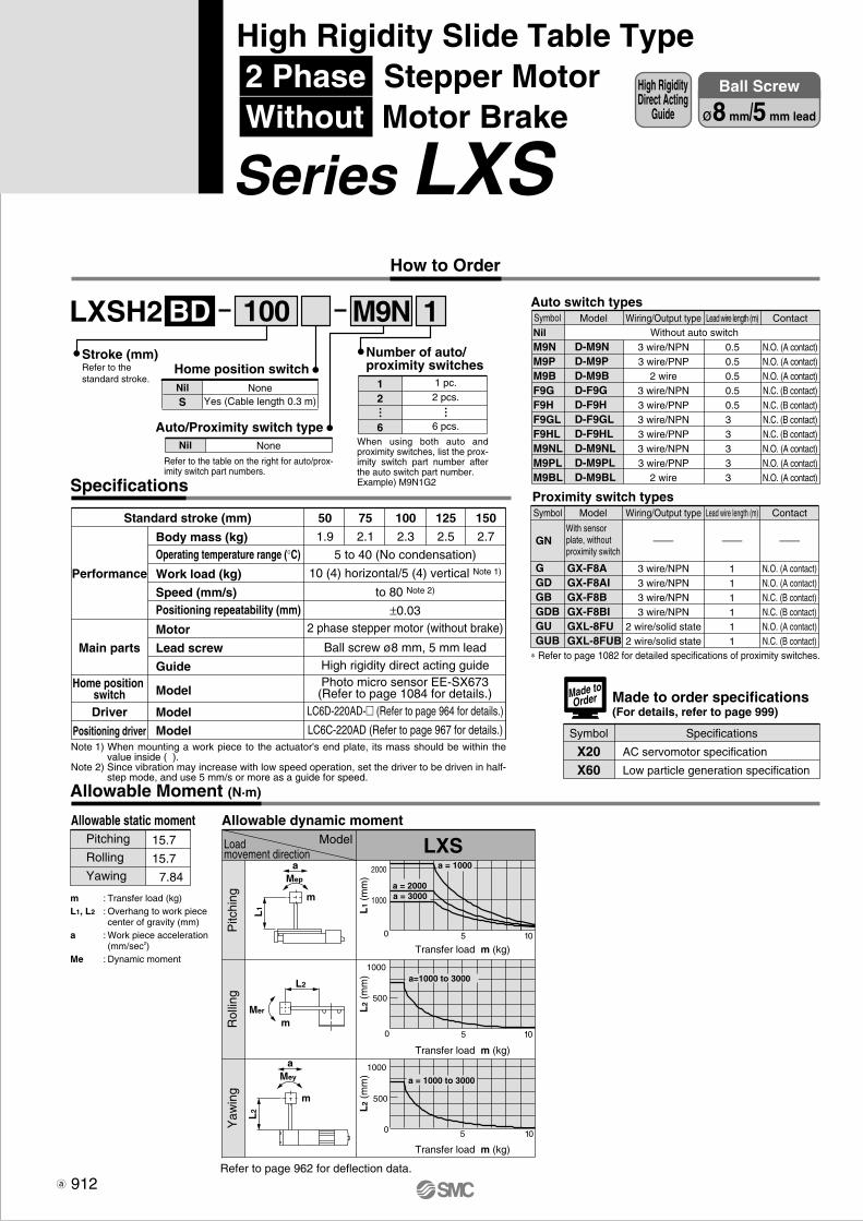
LXSH2 1BD
LXS2000
1000
5 100
5 100
5 100
500
1000
500
1000
a = 1000
a = 2000a = 3000
a=1000 to 3000
a = 1000 to 3000
aMep
L2
Mer
L2
Mey
L1
m
m
m
a
M9N100Stroke (mm)Refer to the standard stroke.
NoneYes (Cable length 0.3 m)
NilS
Home position switch
NoneNil
Auto/Proximity switch type
Refer to the table on the right for auto/prox-imity switch part numbers.
Specifications
Allowable Moment (N·m)
Allowable static moment Allowable dynamic moment
Refer to page 962 for deflection data.
ModelLoadmovement direction
Pitc
hing
Rol
ling
Yaw
ing
Transfer load m (kg)
Transfer load m (kg)
Transfer load m (kg)
L1
(mm
)L
2 (m
m)
L2
(mm
)
Pitching
Rolling
Yawing
15.7
15.7
7.84
m : Transfer load (kg)L1, L2 : Overhang to work piece
center of gravity (mm)a : Work piece acceleration
(mm/sec2)Me : Dynamic moment
Made to order specifications(For details, refer to page 999)
Symbol Specifications
AC servomotor specification
Low particle generation specification
X20X60
Made toOrder
912
High RigidityDirect Acting
Guide
Ball Screw
ø8 mm/5 mm lead
High Rigidity Slide Table Type 2 Phase Stepper Motor Without Motor Brake
Series LXS How to Order
Auto switch types
NilM9NM9PM9BF9GF9HF9GLF9HLM9NLM9PLM9BL
D-M9ND-M9PD-M9BD-F9GD-F9HD-F9GLD-F9HLD-M9NLD-M9PLD-M9BL
Model Wiring/Output type
3 wire/NPN3 wire/PNP
2 wire3 wire/NPN3 wire/PNP3 wire/NPN3 wire/PNP3 wire/NPN3 wire/PNP
2 wire
Lead wire length (m)
0.50.50.50.50.53 3 3 3 3
Contact
N.O. (A contact)N.O. (A contact)N.O. (A contact)N.C. (B contact)N.C. (B contact)N.C. (B contact)N.C. (B contact)N.O. (A contact)N.O. (A contact)N.O. (A contact)
Proximity switch typesSymbol
GGDGBGDBGUGUB
GN
GX-F8AGX-F8AIGX-F8BGX-F8BIGXL-8FUGXL-8FUB
Model Wiring/Output type
3 wire/NPN3 wire/NPN3 wire/NPN3 wire/NPN
2 wire/solid state2 wire/solid state
Lead wire length (m)
111111
Contact
——————
N.O. (A contact)N.O. (A contact)N.C. (B contact)N.C. (B contact)N.O. (A contact)N.C. (B contact)
∗ Refer to page 1082 for detailed specifications of proximity switches.
Without auto switchSymbol
Body mass (kg)Operating temperature range (°C)
Work load (kg)
Speed (mm/s)Positioning repeatability (mm)
Motor
Lead screw
Guide
Model
Model
Model
50
1.9
75
2.1
100
2.3
125
2.5
150
2.7
5 to 40 (No condensation)
10 (4) horizontal/5 (4) vertical Note 1)
to 80 Note 2)
±0.032 phase stepper motor (without brake)
Ball screw ø8 mm, 5 mm leadHigh rigidity direct acting guide
LC6D-220AD-� (Refer to page 964 for details.)
LC6C-220AD (Refer to page 967 for details.)
Performance
Main parts
Home position switchDriver
Positioning driver
Standard stroke (mm)
Note 1) When mounting a work piece to the actuator's end plate, its mass should be within the value inside ( ).
Note 2) Since vibration may increase with low speed operation, set the driver to be driven in half-step mode, and use 5 mm/s or more as a guide for speed.
Photo micro sensor EE-SX673(Refer to page 1084 for details.)
1 pc.2 pcs.
6 pcs.
12
6
Number of auto/proximity switches
… …
When using both auto and proximity switches, list the prox-imity switch part number after the auto switch part number.Example) M9N1G2
With sensor plate, without proximity switch

10
40
80
1
0.2
0.1
0.4
10
1.1
0.3
0.2
50
5.1
1.3
0.7
100
10.1
2.6
1.3
150
15.1
3.8
1.9
10
40
80
1
0.2
0.1
0.1
10
1.1
0.3
0.2
50
5.1
1.3
0.7
150
15.1
3.8
1.9
100
10.1
2.6
1.3
10
40
80
1
0.2
0.1
0.1
10
1.1
0.3
0.2
50
5.1
1.3
0.7
100
10.1
2.6
1.3
150
15.1
3.8
1.9
C
C
6.5
6.5
3.3
5.8
13
20
28
5
15(5)
0.5
46.5
13 15
3.5
27 19
6
38
58
52 58
76 46
2525
8
10
3
36
U(52)
28
27.5
10.5
4 5.5
10
6.5
39
(39)
J
27
N
F
10
107.5
LXSH2BD- 50LXSH2BD- 75LXSH2BD-100LXSH2BD-125LXSH2BD-150
D44446
E66888
F107112122132112
G5565758565
I11112
J6575657075
K22333
L66668
N5565758565
P22223
U5247474747
J x K
G x I
E x M5 thread depth 10 5H
9+0
.030
0de
pth
5
ø5H9+0.030 0 depth 5 D x ø5.1 through
Refer to Cross section C-C, bottom view.
Motor wire (300 mm)Photo micro sensor wire (300 mm)
2 x M2.5thread depth 4
Stroke + 220
Stroke + 127Stroke + 127
2 x M6thread depth 13
Stroke + 127
∗ The dimension inside [ ] shows the location at which the home position switch operates.
[18]∗
ø4H9+0.030 0 depth 4
4H9 +0.030 0 depth 4
L x M6Refer to Crosssection C-C.
T-slot ABody mounting reference plane
1 ±0
.2(ø
5.1)
36: T
-slo
t pitc
h
T-slot B
Work piece mountingreference plane
Cross section C-C
T-slot Adimension
T-slot Bdimension
N x P
Speed(mm/s)
913
Dimensions/LXSH2BD
Model
Refer to page 959 for mounting.
For transfer load of 0 kgPositioning time (sec)
Positioning distance (mm)
For transfer load of 10 kg
For transfer load of 5 kgPositioning time (sec)
Positioning distance (mm)
Speed(mm/s)
Positioning time (sec)
Positioning distance (mm)
Speed(mm/s)
Positioning Time Guide (for Horizontal Mount)
Refer to page 961 for acceleration time.
Series LXSHigh Rigidity Slide Table Type 2 Phase Stepper Motor/Without Motor Brake
LJ1
LG1
LTF
LC1
LC7
LC8
LXF
LXP
LXS
LC6�
LZ�
LC3F2
X�
D-�
E-MY
P0910-P0941-E.qxd 10.12.15 11:50 AM Page 913

2000
1000
5 100
5 100
5 100
500
1000
500
1000
a = 1000
a = 2000a = 3000
a = 1000 to 3000
a = 1000 to 3000
LXSH2 1SA
LXSa
Mep
L2
Mer
L2
Mey
L1
m
m
m
a
M9N100 Auto switch types
NilM9NM9PM9BF9GF9HF9GLF9HLM9NLM9PLM9BL
D-M9ND-M9PD-M9BD-F9GD-F9HD-F9GLD-F9HLD-M9NLD-M9PLD-M9BL
Model Wiring/Output type
3 wire/NPN3 wire/PNP
2 wire3 wire/NPN3 wire/PNP3 wire/NPN3 wire/PNP3 wire/NPN3 wire/PNP
2 wire
Lead wire length (m)
0.50.50.50.50.53 3 3 3 3
Contact
N.O. (A contact)N.O. (A contact)N.O. (A contact)N.C. (B contact)N.C. (B contact)N.C. (B contact)N.C. (B contact)N.O. (A contact)N.O. (A contact)N.O. (A contact)
Proximity switch typesSymbol
GGDGBGDBGUGUB
GN
GX-F8AGX-F8AIGX-F8BGX-F8BIGXL-8FUGXL-8FUB
Model Wiring/Output type
3 wire/NPN3 wire/NPN3 wire/NPN3 wire/NPN
2 wire/solid state2 wire/solid state
Lead wire length (m)
111111
Contact
——————
N.O. (A contact)N.O. (A contact)N.C. (B contact)N.C. (B contact)N.O. (A contact)N.C. (B contact)
∗ Refer to page 1082 for detailed specifications of proximity switches.
Without auto switchSymbol
Specifications
Body mass (kg)Operating temperature range (°C)
Work load (kg)
Speed (mm/s)Positioning repeatability (mm)
Motor
Lead screw
Guide
Model
Model
Model
50
1.9
75
2.1
100
2.3
125
2.5
150
2.7
5 to 40 (No condensation)
9 (4) horizontal/4 (4) vertical Note 1)
to 100 Note 2)
±0.052 phase stepper motor (without brake)
Slide screw ø8 mm, 6 mm leadHigh rigidity direct acting guide
LC6D-220AD-� (Refer to page 964 for details.)
LC6C-220AD (Refer to page 967 for details.)
Performance
Main parts
Home position switchDriver
Positioning driver
Standard stroke (mm)
Note 1) When mounting a work piece to the actuator's end plate, its mass should be within the value inside ( ).
Note 2) Since vibration may increase with low speed operation, set the driver to be driven in half-step mode, and use 6 mm/s or more as a guide for speed.
Allowable Moment (N·m)
Allowable static moment
Refer to page 962 for deflection data.
ModelLoadmovement direction
Pitc
hing
Rol
ling
Yaw
ing
Transfer load m (kg)
Transfer load m (kg)
Transfer load m (kg)
L1
(mm
)L
2 (m
m)
L2
(mm
)
Pitching
Rolling
Yawing
15.7
15.7
7.84
m : Transfer load (kg)L1, L2 : Overhang to work piece
center of gravity (mm)a : Work piece acceleration
(mm/sec2)Me : Dynamic moment
Photo micro sensor EE-SX673(Refer to page 1084 for details.)
Allowable dynamic moment
With sensor plate, without proximity switch
914
High RigidityDirect Acting
Guide
Slide Screw
ø8 mm/6 mm lead
High Rigidity Slide Table Type 2 Phase Stepper Motor Without Motor Brake
Series LXS How to Order
Stroke (mm)Refer to the standard stroke. None
Yes (Cable length 0.3 m)NilS
Home position switch
NoneNil
Auto/Proximity switch type
Refer to the table on the right for auto/prox-imity switch part numbers.
1 pc.2 pcs.
6 pcs.
12
6
Number of auto/proximity switches
… …
When using both auto and proximity switches, list the prox-imity switch part number after the auto switch part number.Example) M9N1G2
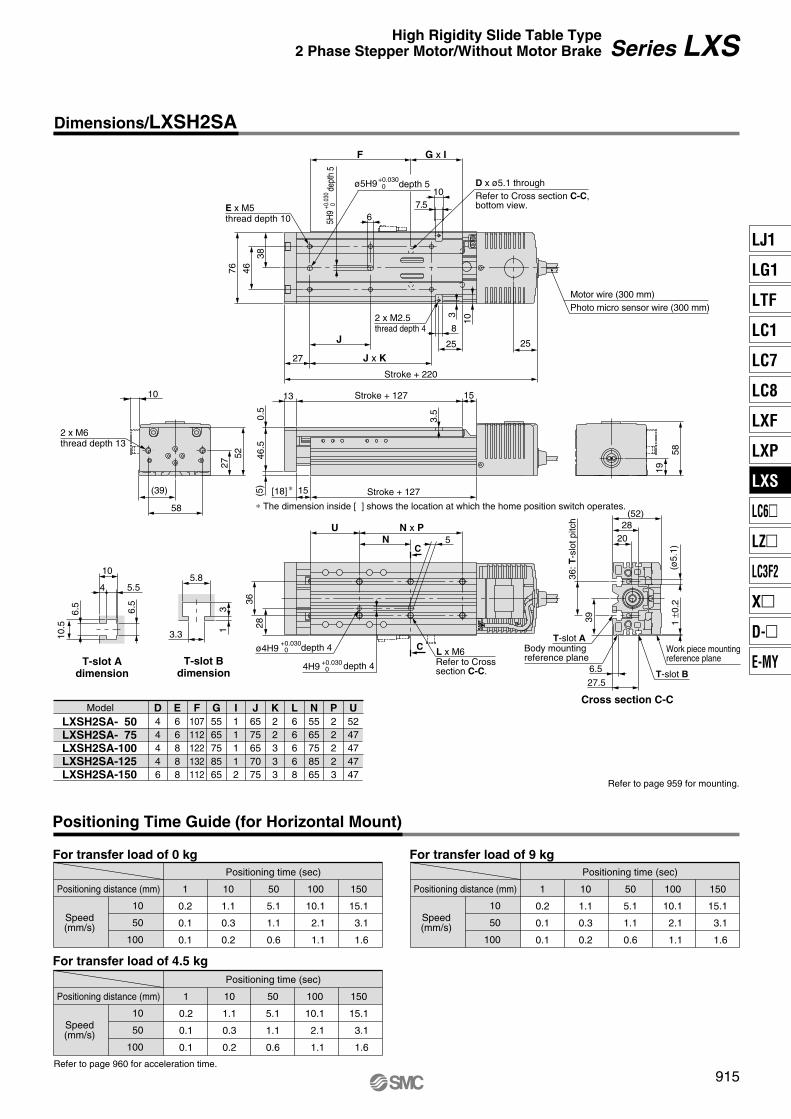
10
50
100
1
0.2
0.1
0.1
10
1.1
0.3
0.2
50
5.1
1.1
0.6
100
10.1
2.1
1.1
150
15.1
3.1
1.6
10
50
100
1
0.2
0.1
0.1
10
1.1
0.3
0.2
50
5.1
1.1
0.6
150
15.1
3.1
1.6
100
10.1
2.1
1.1
10
50
100
1
0.2
0.1
0.1
10
1.1
0.3
0.2
50
5.1
1.1
0.6
100
10.1
2.1
1.1
150
15.1
3.1
1.6
C
C
6.5
6.5
3.3
5.8
13
20
28
5
15(5)
0.5
46.5
13 15
3.5
27 19
6
38
58
52 58
76 46
2525
8
10
3
36
U(52)
28
27.5
10.5
4 5.5
10
6.5
39
(39)
J
27
N
F G x I
10
107.5
LXSH2SA- 50LXSH2SA- 75LXSH2SA-100LXSH2SA-125LXSH2SA-150
D44446
E66888
F107112122132112
G5565758565
I11112
J6575657075
K22333
L66668
N5565758565
P22223
U5247474747
Stroke + 127
2 x M6thread depth 13
Stroke + 127
∗ The dimension inside [ ] shows the location at which the home position switch operates.
[18]∗
N x P
ø4H9+0.030 0 depth 4
4H9 +0.030 0 depth 4
L x M6Refer to Crosssection C-C.
T-slot ABody mounting reference plane
1 ±0
.2(ø
5.1)
36: T
-slo
t pitc
h
T-slot B
Work piece mountingreference plane
Cross section C-C
T-slot Adimension
T-slot Bdimension
Refer to page 959 for mounting.
Model
Speed(mm/s)
For transfer load of 0 kgPositioning time (sec)
Positioning distance (mm)
For transfer load of 9 kg
For transfer load of 4.5 kgPositioning time (sec)
Positioning distance (mm)
Speed(mm/s)
Positioning time (sec)
Positioning distance (mm)
Speed(mm/s)
Positioning Time Guide (for Horizontal Mount)
Refer to page 960 for acceleration time.
915
Dimensions/LXSH2SA
J x K
E x M5 thread depth 10 5H
9+0
.030
0de
pth
5
ø5H9+0.030 0 depth 5 D x ø5.1 through
Refer to Cross section C-C, bottom view.
Motor wire (300 mm)Photo micro sensor wire (300 mm)
2 x M2.5thread depth 4
Stroke + 220
Series LXSHigh Rigidity Slide Table Type 2 Phase Stepper Motor/Without Motor Brake
LJ1
LG1
LTF
LC1
LC7
LC8
LXF
LXP
LXS
LC6�
LZ�
LC3F2
X�
D-�
E-MY
P0910-P0941-E.qxd 10.12.15 11:50 AM Page 915
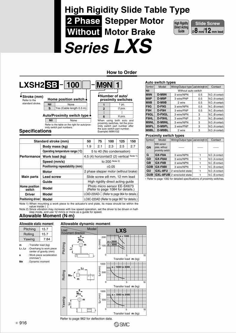
2000
1000
5 100
5 100
5 100
500
1000
500
1000
a = 1000
a = 2000a = 3000
a = 1000 to 3000
a = 1000 to 3000
LXSH2 1SB
LXSa
Mep
L2
Mer
L2
Mey
L1
m
m
m
a
M9N100 Auto switch types
NilM9NM9PM9BF9GF9HF9GLF9HLM9NLM9PLM9BL
D-M9ND-M9PD-M9BD-F9GD-F9HD-F9GLD-F9HLD-M9NLD-M9PLD-M9BL
Model Wiring/Output type
3 wire/NPN3 wire/PNP
2 wire3 wire/NPN3 wire/PNP3 wire/NPN3 wire/PNP3 wire/NPN3 wire/PNP
2 wire
Lead wire length (m)
0.50.50.50.50.53 3 3 3 3
Contact
N.O. (A contact)N.O. (A contact)N.O. (A contact)N.C. (B contact)N.C. (B contact)N.C. (B contact)N.C. (B contact)N.O. (A contact)N.O. (A contact)N.O. (A contact)
Proximity switch typesSymbol
GGDGBGDBGUGUB
GN
GX-F8AGX-F8AIGX-F8BGX-F8BIGXL-8FUGXL-8FUB
Model Wiring/Output type
3 wire/NPN3 wire/NPN3 wire/NPN3 wire/NPN
2 wire/solid state2 wire/solid state
Lead wire length (m)
111111
Contact
——————
N.O. (A contact)N.O. (A contact)N.C. (B contact)N.C. (B contact)N.O. (A contact)N.C. (B contact)
∗ Refer to page 1082 for detailed specifications of proximity switches.
Without auto switchSymbol
Allowable Moment (N·m)
Allowable static moment Allowable dynamic moment
Refer to page 962 for deflection data.
ModelLoadmovement direction
Pitc
hing
Rol
ling
Yaw
ing
Transfer load m (kg)
Transfer load m (kg)
Transfer load m (kg)
L1
(mm
)L
2 (m
m)
L2
(mm
)
Pitching
Rolling
Yawing
15.7
15.7
7.84
m : Transfer load (kg)L1, L2 : Overhang to work piece
center of gravity (mm)a : Work piece acceleration
(mm/sec2)Me : Dynamic moment
With sensor plate, without proximity switch
Refer to the standard stroke.
916
High RigidityDirect Acting
Guide
Slide Screw
ø8 mm/12 mm lead
High Rigidity Slide Table Type 2 Phase Stepper Motor Without Motor Brake
Series LXS How to Order
Stroke (mm)
NoneYes (Cable length 0.3 m)
NilS
Home position switch
NoneNil
Auto/Proximity switch type
Refer to the table on the right for auto/prox-imity switch part numbers.
1 pc.2 pcs.
6 pcs.
12
6
Number of auto/proximity switches
… …
When using both auto and proximity switches, list the prox-imity switch part number after the auto switch part number.Example) M9N1G2Specifications
Body mass (kg)Operating temperature range (°C)
Work load (kg)
Speed (mm/s)Positioning repeatability (mm)
Motor
Lead screw
Guide
Model
Model
Model
50
1.9
75
2.1
100
2.3
125
2.5
150
2.7
5 to 40 (No condensation)
4.5 (4) horizontal/2 (2) vertical Note 1)
to 200 Note 2)
±0.052 phase stepper motor (without brake)
Slide screw ø8 mm, 12 mm leadHigh rigidity direct acting guide
LC6D-220AD-� (Refer to page 964 for details.)
LC6C-220AD (Refer to page 967 for details.)
Performance
Main parts
Home position switchDriver
Positioning driver
Standard stroke (mm)
Note 1) When mounting a work piece to the actuator's end plate, its mass should be within the value inside ( ).
Note 2) Since vibration may increase with low speed operation, set the driver to be driven in half-step mode, and use 12 mm/s or more as a guide for speed.
Photo micro sensor EE-SX673(Refer to page 1084 for details.)

50
100
200
1
0.1
0.1
0.1
10
0.3
0.2
0.1
50
1.1
0.6
0.3
100
2.1
1.1
0.6
150
3.1
1.6
0.8
50
100
200
1
0.1
0.1
0.1
10
0.3
0.2
0.1
50
1.1
0.6
0.3
150
3.1
1.6
0.8
100
2.1
1.1
0.6
50
100
200
1
0.1
0.1
0.1
10
0.3
0.2
0.2
50
1.1
0.6
0.4
100
2.1
1.1
0.6
150
3.1
1.6
0.9
C
C
6.5
6.5
3.3
5.8
13
20
28
5
15(5)
0.5
46.5
13 15
3.5
27
19
6
38
58
52 58
76 46
2525
8
10
3
36
U(52)
28
27.5
10.5
4 5.5
10
6.5
39
(39)
J
27
N
F
10
107.5
LXSH2SB- 50LXSH2SB- 75LXSH2SB-100LXSH2SB-125LXSH2SB-150
D44446
E66888
F107112122132112
G5565758565
I11112
J6575657075
K22333
L66668
N5565758565
P22223
U5247474747
2 x M6thread depth 13
Stroke + 127
∗ The dimension inside [ ] shows the location at which the home position switch operates.
[18]∗
ø4H9+0.030 0 depth 4
4H9 +0.030 0 depth 4
L x M6Refer to Crosssection C-C.
T-slot ABody mounting reference plane
1 ±0
.2(ø
5.1)
36: T
-slo
t pitc
h
T-slot B
Work piece mountingreference plane
Cross section C-C
T-slot Adimension
T-slot Bdimension
N x P
Model
Speed(mm/s)
For transfer load of 0 kgPositioning time (sec)
Positioning distance (mm)
For transfer load of 4.5 kg
For transfer load of 2.5 kgPositioning time (sec)
Positioning distance (mm)
Speed(mm/s)
Positioning time (sec)
Positioning distance (mm)
Speed(mm/s)
Positioning Time Guide (for Horizontal Mount)
Refer to page 960 for acceleration time.
Refer to page 959 for mounting.
G x I
917
Series LXSHigh Rigidity Slide Table Type 2 Phase Stepper Motor/Without Motor Brake
Dimensions/LXSH2SB
J x K
E x M5 thread depth 10 5H
9+0
.030
0de
pth
5
ø5H9+0.030 0 depth 5 D x ø5.1 through
Refer to Cross section C-C, bottom view.
Motor wire (300 mm)Photo micro sensor wire (300 mm)
2 x M2.5thread depth 4
Stroke + 220
Stroke + 127
LJ1
LG1
LTF
LC1
LC7
LC8
LXF
LXP
LXS
LC6�
LZ�
LC3F2
X�
D-�
E-MY
P0910-P0941-E.qxd 10.12.15 11:50 AM Page 917
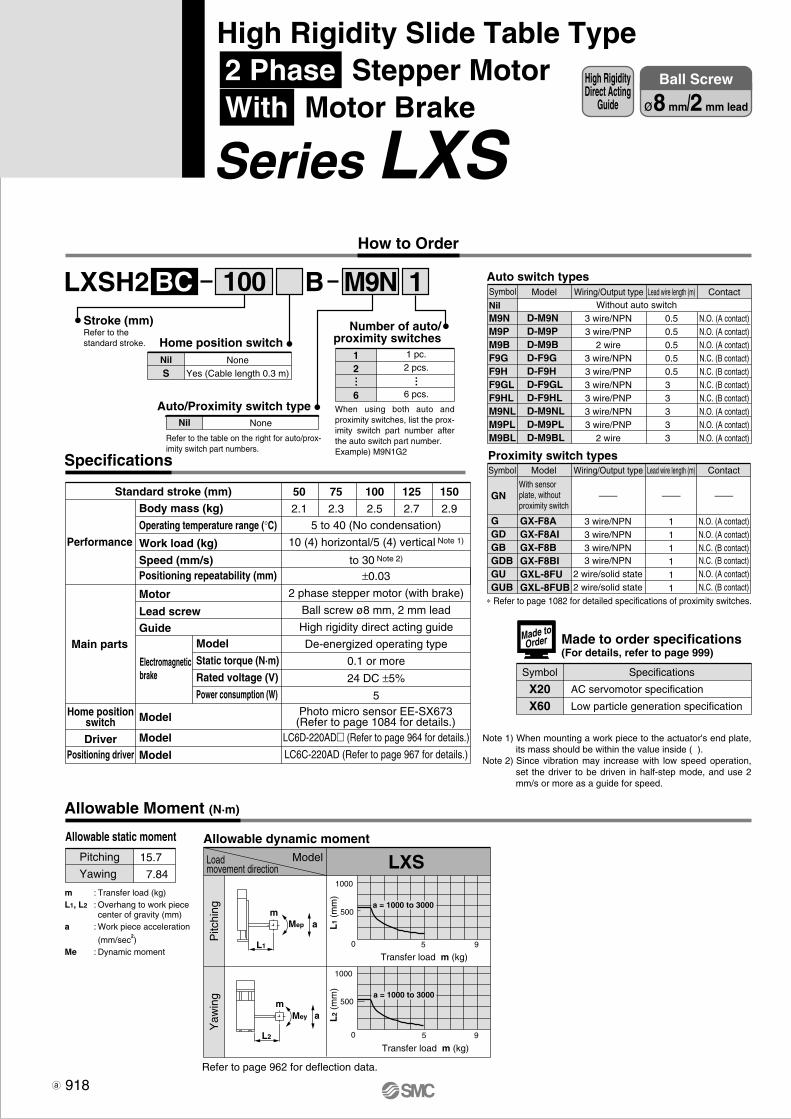
LXSH2 1BBC
Allowable Moment (N·m)
M9N
Allowable dynamic moment
LXSModelLoadmovement direction
Pitc
hing
Yaw
ing
Transfer load m (kg)
Transfer load m (kg)
L1
(mm
)L
2 (m
m)
Refer to page 962 for deflection data.
m
L2
1000
500
5 90
5 90
1000
500a = 1000 to 3000
a = 1000 to 3000
Mep
L1
Mey a
am
Auto switch types
M9NM9PM9BF9GF9HF9GLF9HLM9NLM9PLM9BL
D-M9ND-M9PD-M9BD-F9GD-F9HD-F9GLD-F9HLD-M9NLD-M9PLD-M9BL
Model
3 wire/NPN3 wire/PNP
2 wire3 wire/NPN3 wire/PNP3 wire/NPN3 wire/PNP3 wire/NPN3 wire/PNP
2 wire
0.50.50.50.50.53 3 3 3 3
N.O. (A contact)N.O. (A contact)N.O. (A contact)N.C. (B contact)N.C. (B contact)N.C. (B contact)N.C. (B contact)N.O. (A contact)N.O. (A contact)N.O. (A contact)
Proximity switch typesSymbol
GGDGBGDBGUGUB
GN
GX-F8AGX-F8AIGX-F8BGX-F8BIGXL-8FUGXL-8FUB
Model Wiring/Output type
3 wire/NPN3 wire/NPN3 wire/NPN3 wire/NPN
2 wire/solid state2 wire/solid state
Lead wire length (m)
111111
Contact
——————
N.O. (A contact)N.O. (A contact)N.C. (B contact)N.C. (B contact)N.O. (A contact)N.C. (B contact)
∗ Refer to page 1082 for detailed specifications of proximity switches.
Without auto switch
Note 1) When mounting a work piece to the actuator's end plate, its mass should be within the value inside ( ).
Note 2) Since vibration may increase with low speed operation, set the driver to be driven in half-step mode, and use 2 mm/s or more as a guide for speed.
100Stroke (mm)Refer to the standard stroke.
Symbol
NilWiring/Output type Lead wire length (m) Contact
50
2.1
75
2.3
100
2.5
125
2.7
150
2.9
5 to 40 (No condensation)
10 (4) horizontal/5 (4) vertical Note 1)
to 30 Note 2)
±0.03
2 phase stepper motor (with brake)
Ball screw ø8 mm, 2 mm lead
High rigidity direct acting guide
De-energized operating type
0.1 or more
24 DC ±5%
5
LC6D-220AD� (Refer to page 964 for details.)
LC6C-220AD (Refer to page 967 for details.)
Performance
Main parts
Home positionswitch
DriverPositioning driver
Body mass (kg)
Operating temperature range (°C)
Work load (kg)
Speed (mm/s)Positioning repeatability (mm)
Motor
Lead screwGuide
Model
Model
Model
Standard stroke (mm)
Electromagneticbrake
Model
Static torque (N·m)
Rated voltage (V)
Power consumption (W)
Specifications
Allowable static moment
Pitching
Yawing
15.7
7.84
m : Transfer load (kg)L1, L2 : Overhang to work piece
center of gravity (mm)a : Work piece acceleration
(mm/sec2)
Me : Dynamic moment
Photo micro sensor EE-SX673(Refer to page 1084 for details.)
Made to order specifications(For details, refer to page 999)
Symbol Specifications
AC servomotor specification
Low particle generation specification
X20X60
Made toOrder
With sensor plate, without proximity switch
918
How to Order
High RigidityDirect Acting
Guide
Ball Screw
ø8 mm/2 mm lead
High Rigidity Slide Table Type 2 Phase Stepper Motor With Motor Brake
Series LXS
NoneYes (Cable length 0.3 m)
NilS
Home position switch
NoneNil
Auto/Proximity switch type
Refer to the table on the right for auto/prox-imity switch part numbers.
1 pc.2 pcs.
6 pcs.
Number of auto/proximity switches
12
6
… …
When using both auto and proximity switches, list the prox-imity switch part number after the auto switch part number.Example) M9N1G2

For transfer load of 0 kg For transfer load of 5 kg
For transfer load of 2.5 kgPositioning time (sec)
Positioning distance (mm)
Speed(mm/s)
10
20
30
1
0.2
0.1
0.1
10
1.1
0.6
0.4
50
5.1
2.6
1.7
150
15.1
7.6
5.1
100
10.1
5.1
3.4
Positioning time (sec)
Positioning distance (mm)
Speed(mm/s)
10
20
30
1
0.2
0.1
0.1
10
1.1
0.6
0.4
50
5.1
2.6
1.7
150
15.1
7.6
5.1
100
10.1
5.1
3.4
Positioning time (sec)
Positioning distance (mm)
Speed(mm/s)
10
20
30
1
0.2
0.1
0.1
10
1.1
0.6
0.4
50
5.1
2.6
1.7
200
15.1
7.6
5.1
100
10.1
5.1
3.4
Brake electrical circuit
Note) A contact protection circuit isrequired when connecting a brake.
+24 V
0 V
59
16
75.5
384676
27 25
8
10
3
6
15(5)
0.5
46.5
13 153.
5
C
C
28
N x P5
U
36
6.5
6.5
3.3
5.8
13
Cross section C-C
10.5
4 5.5
10 36: T
-slo
t pitc
h
20
(52)
28
27.5
6.5
39
27
58
52
(39)
J x KJ
N
Brown
White
F G x I
107.5
Refer to page 959 for mounting.
Model
LXSH2BC- 50�BLXSH2BC- 75�BLXSH2BC-100�BLXSH2BC-125�BLXSH2BC-150�B
D44446
E66888
F107112122132112
G5565758565
I11112
J6575657075
K22333
L66668
N5565758565
P22223
U5247474747
Refer to page 961 for acceleration time.
E x M5thread depth 10 5H
9+0
.030
0de
pth
5
ø5H9 +0.030 0 depth 5
D x ø5.1 through
Refer to Cross section C-C, bottom view.
2 x M2.5thread depth 4
Stroke + 246Motor wire (300 mm)
Photo micro sensor wire (300 mm)Brake wire (300 mm)
2 x M6thread depth 13
[18]∗
Stroke + 127
Stroke + 127
∗ The dimension inside [ ] shows the location at which the home position switch operates.
T-slot Bdimension
T-slot Adimension
ø4H9+0.030 0 depth 4
4H9
+0.0
30 0
dept
h 4
L x M6Refer to Crosssection C-C.
Body mounting reference plane
T-slot A
T-slot B
Work piece mountingreference plane
(ø5.
1)1
±0.2
Dimensions/LXSH2BC
Positioning Time Guide (for Vertical Mount)
919
Series LXSHigh Rigidity Slide Table Type 2 Phase Stepper Motor/With Motor Brake
LJ1
LG1
LTF
LC1
LC7
LC8
LXF
LXP
LXS
LC6�
LZ�
LC3F2
X�
D-�
E-MY
P0910-P0941-E.qxd 10.12.15 11:50 AM Page 919

LXSH2 1BBD M9N
LXS
m
L2
1000
500
5 90
5 90
1000
500a = 1000 to 3000
a = 1000 to 3000
Mep
L1
Mey a
am
100Stroke (mm)Refer to the standard stroke.
NoneYes (Cable length 0.3 m)
NilS
Home position switch
NoneNil
Auto/Proximity switch type
Refer to the table on the right for auto/prox-imity switch part numbers.
1 pc.2 pcs.
6 pcs.
Number of auto/proximity switches
12
6
… …
When using both auto and proximity switches, list the prox-imity switch part number after the auto switch part number.Example) M9N1G2
Auto switch types
NilM9NM9PM9BF9GF9HF9GLF9HLM9NLM9PLM9BL
D-M9ND-M9PD-M9BD-F9GD-F9HD-F9GLD-F9HLD-M9NLD-M9PLD-M9BL
Model
3 wire/NPN3 wire/PNP
2 wire3 wire/NPN3 wire/PNP3 wire/NPN3 wire/PNP3 wire/NPN3 wire/PNP
2 wire
0.50.50.50.50.53 3 3 3 3
N.O. (A contact)N.O. (A contact)N.O. (A contact)N.C. (B contact)N.C. (B contact)N.C. (B contact)N.C. (B contact)N.O. (A contact)N.O. (A contact)N.O. (A contact)
Proximity switch typesSymbol
GGDGBGDBGUGUB
GN
GX-F8AGX-F8AIGX-F8BGX-F8BIGXL-8FUGXL-8FUB
Model Wiring/Output type
3 wire/NPN3 wire/NPN3 wire/NPN3 wire/NPN
2 wire/solid state2 wire/solid state
Lead wire length (m)
111111
Contact
——————
N.O. (A contact)N.O. (A contact)N.C. (B contact)N.C. (B contact)N.O. (A contact)N.C. (B contact)
With sensor plate, without proximity switch
∗ Refer to page 1082 for detailed specifications of proximity switches.
Without auto switchSymbol Wiring/Output type Lead wire length (m) Contact
Note 1) When mounting a work piece to the actuator's end plate, its mass should be within the value inside ( ).
Note 2) Since vibration may increase with low speed operation, set the driver to be driven in half-step mode, and use 5 mm/s or more as a guide for speed.
50
2.1
75
2.3
100
2.5
125
2.7
150
2.9
5 to 40 (No condensation)
10 (4) horizontal/5 (4) vertical Note 1)
to 80 Note 2)
±0.03
2 phase stepper motor (with brake)
Ball screw ø8 mm, 5 mm lead
High rigidity direct acting guide
De-energized operating type
0.1 or more
24 DC ±5%
5
LC6D-220AD-� (Refer to page 964 for details.)
LC6C-220AD (Refer to page 967 for details.)
Performance
Main parts
Home positionswitch
DriverPositioning driver
Body mass (kg)
Operating temperature range (°C)
Work load (kg)
Speed (mm/s)Positioning repeatability (mm)
Motor
Lead screwGuide
Model
Model
Model
Standard stroke (mm)
Electromagneticbrake
Model
Static torque (N·m)
Rated voltage (V)
Power consumption (W)
Specifications
Allowable Moment (N·m)
Allowable dynamic momentModelLoad
movement direction
Pitc
hing
Yaw
ing
Transfer load m (kg)
Transfer load m (kg)
L1
(mm
)L
2 (m
m)
Refer to page 962 for deflection data.
Allowable static moment
Pitching
Yawing
15.7
7.84
m : Transfer load (kg)L1, L2 : Overhang to work piece
center of gravity (mm)a : Work piece acceleration
(mm/sec2)Me : Dynamic moment
Photo micro sensor EE-SX673(Refer to page 1084 for details.)
Made to order specifications(For details, refer to page 999)
Symbol Specifications
AC servomotor specification
Low particle generation specification
X20X60
Made toOrder
920
High RigidityDirect Acting
Guide
Ball Screw
ø8 mm/5 mm lead
High Rigidity Slide Table Type 2 Phase Stepper Motor With Motor Brake
Series LXS How to Order

10
40
80
1
0.2
0.1
0.1
10
1.1
0.3
0.2
50
5.1
1.3
0.7
150
15.1
3.8
2.0
100
10.1
2.6
1.3
10
40
80
1
0.2
0.1
0.1
10
1.1
0.3
0.2
50
5.1
1.3
0.7
150
15.1
3.8
1.9
100
10.1
2.6
1.3
10
40
80
1
0.1
0.1
0.1
10
1
0.3
0.2
50
5
1.3
0.7
200
20
5.1
2.6
100
10
2.6
1.3
59
16
75.5
384676
27 25
8
103
6
15(5)
0.5
46.5
13 153.
5
C
C
28
5U
36
6.5
6.5
3.3
5.8
1310
.5
4 5.5
10
20
(52)
28
27.5
6.5
39
27
58
52
(39)
J
N
F G x I
107.5
ModelLXSH2BD- 50�BLXSH2BD- 75�BLXSH2BD-100�BLXSH2BD-125�BLXSH2BD-150�B
D44446
E66888
F107112122132112
G5565758565
I11112
J6575657075
K22333
L66668
N5565758565
P22223
U5247474747
5H9
+0.0
30 0
dept
h 5
ø5H9 +0.030 0 depth 5
D x ø5.1 throughRefer to Cross section C-C, bottom view.
2 x M2.5thread depth 4
J x K
Stroke + 246
Brake electrical circuit
Note) A contact protection circuit isrequired when connecting a brake.
+24 V
0 V
Brown
White
Motor wire (300 mm)
Photo micro sensor wire (300 mm)Brake wire (300 mm)
[18]∗
Stroke + 127
Stroke + 127
∗ The dimension inside [ ] shows the location at which the home position switch operates.
T-slot Bdimension
T-slot Adimension
ø4H9+0.030 0 depth 4
4H9
+0.0
30 0
dept
h 4
L x M6Refer to Crosssection C-C.
N x P
Cross section C-C
36: T
-slo
t pitc
h
Body mounting reference plane
T-slot A
T-slot B
Work piece mountingreference plane
(ø5.
1)1
±0.2
Refer to page 959 for mounting.
For transfer load of 0 kg For transfer load of 5 kg
For transfer load of 2.5 kgPositioning time (sec)
Positioning distance (mm)
Speed(mm/s)
Positioning time (sec)
Positioning distance (mm)
Speed(mm/s)
Positioning time (sec)
Positioning distance (mm)
Speed(mm/s)
Positioning Time Guide (for Vertical Mount)
921
Series LXSHigh Rigidity Slide Table Type 2 Phase Stepper Motor/With Motor Brake
Dimensions/LXSH2BD
E x M5thread depth 10
2 x M6thread depth 13
Refer to page 961 for acceleration time.
LJ1
LG1
LTF
LC1
LC7
LC8
LXF
LXP
LXS
LC6�
LZ�
LC3F2
X�
D-�
E-MY
P0910-P0941-E.qxd 10.12.15 11:50 AM Page 921
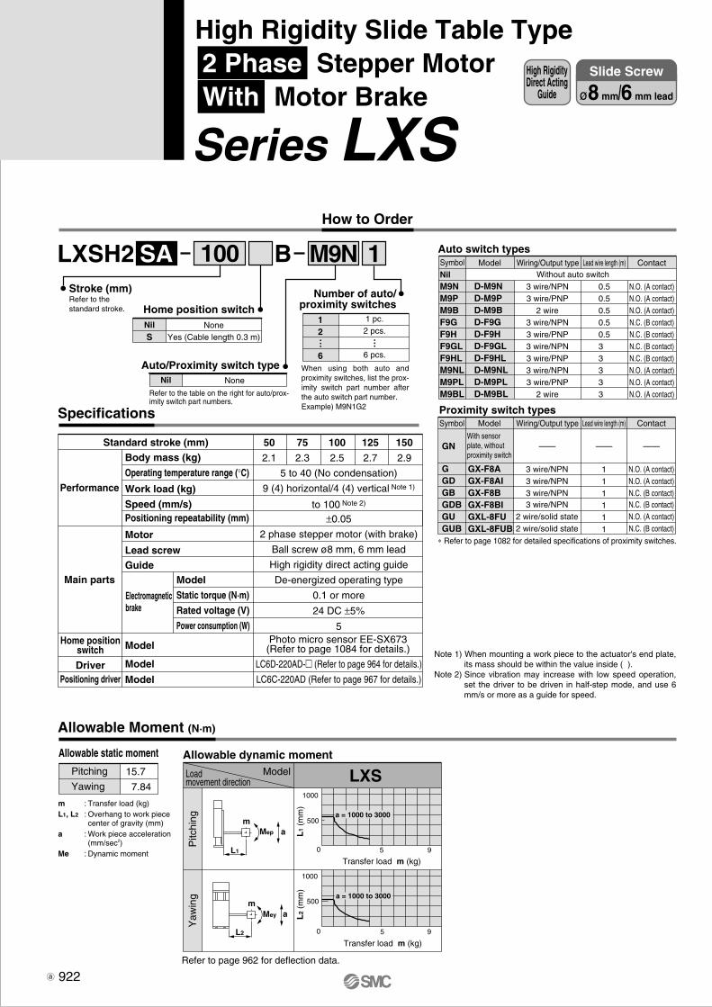
1000
500
5 90
5 90
1000
500a = 1000 to 3000
a = 1000 to 3000
LXSH2 1BSA M9N
LXS
m
L2
Mep
L1
Mey a
am
100
1 pc.2 pcs.
6 pcs.
12
6
Number of auto/proximity switches
… …
When using both auto and proximity switches, list the prox-imity switch part number after the auto switch part number.Example) M9N1G2
Auto switch types
NilM9NM9PM9BF9GF9HF9GLF9HLM9NLM9PLM9BL
D-M9ND-M9PD-M9BD-F9GD-F9HD-F9GLD-F9HLD-M9NLD-M9PLD-M9BL
Model
3 wire/NPN3 wire/PNP
2 wire3 wire/NPN3 wire/PNP3 wire/NPN3 wire/PNP3 wire/NPN3 wire/PNP
2 wire
0.50.50.50.50.53 3 3 3 3
N.O. (A contact)N.O. (A contact)N.O. (A contact)N.C. (B contact)N.C. (B contact)N.C. (B contact)N.C. (B contact)N.O. (A contact)N.O. (A contact)N.O. (A contact)
Proximity switch typesSymbol
GGDGBGDBGUGUB
GN
GX-F8AGX-F8AIGX-F8BGX-F8BIGXL-8FUGXL-8FUB
Model Wiring/Output type
3 wire/NPN3 wire/NPN3 wire/NPN3 wire/NPN
2 wire/solid state2 wire/solid state
Lead wire length (m)
111111
Contact
——————
N.O. (A contact)N.O. (A contact)N.C. (B contact)N.C. (B contact)N.O. (A contact)N.C. (B contact)
With sensor plate, without proximity switch
∗ Refer to page 1082 for detailed specifications of proximity switches.
Without auto switchSymbol Wiring/Output type Lead wire length (m) Contact
Note 1) When mounting a work piece to the actuator's end plate, its mass should be within the value inside ( ).
Note 2) Since vibration may increase with low speed operation, set the driver to be driven in half-step mode, and use 6 mm/s or more as a guide for speed.
50
2.1
75
2.3
100
2.5
125
2.7
150
2.9
5 to 40 (No condensation)
9 (4) horizontal/4 (4) vertical Note 1)
to 100 Note 2)
±0.05
2 phase stepper motor (with brake)
Ball screw ø8 mm, 6 mm lead
High rigidity direct acting guide
De-energized operating type
0.1 or more
24 DC ±5%
5
LC6D-220AD-� (Refer to page 964 for details.)
LC6C-220AD (Refer to page 967 for details.)
Performance
Main parts
Home positionswitch
DriverPositioning driver
Body mass (kg)
Operating temperature range (°C)
Work load (kg)
Speed (mm/s)Positioning repeatability (mm)
Motor
Lead screwGuide
Model
Model
Model
Standard stroke (mm)
Electromagneticbrake
Model
Static torque (N·m)
Rated voltage (V)
Power consumption (W)
Specifications
Allowable Moment (N·m)
Allowable dynamic momentModelLoad
movement direction
Pitc
hing
Yaw
ing
Transfer load m (kg)
Transfer load m (kg)
L1
(mm
)L
2 (m
m)
Refer to page 962 for deflection data.
Allowable static moment
Pitching
Yawing
15.7
7.84
m : Transfer load (kg)L1, L2 : Overhang to work piece
center of gravity (mm)a : Work piece acceleration
(mm/sec2)Me : Dynamic moment
Photo micro sensor EE-SX673(Refer to page 1084 for details.)
922
High RigidityDirect Acting
Guide
Slide Screw
ø8 mm/6 mm lead
High Rigidity Slide Table Type 2 Phase Stepper Motor With Motor Brake
Series LXS How to Order
Stroke (mm)Refer to the standard stroke.
NoneYes (Cable length 0.3 m)
NilS
Home position switch
NoneNil
Auto/Proximity switch type
Refer to the table on the right for auto/prox-imity switch part numbers.
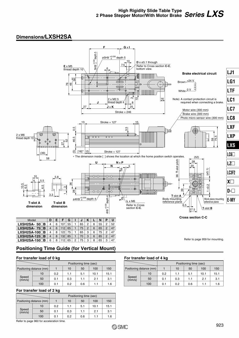
10
50
100
1
0.2
0.1
0.1
10
1.1
0.3
0.2
50
5.1
1.1
0.6
150
15.1
3.1
1.6
100
10.1
2.1
1.1
10
50
100
1
0.2
0.1
0.1
10
1.1
0.3
0.2
50
5.1
1.1
0.6
150
15.1
3.1
1.6
100
10.1
2.1
1.1
10
50
100
1
0.2
0.1
0.1
10
1.1
0.3
0.2
50
5.1
1.1
0.6
150
15.1
3.1
1.6
100
10.1
2.1
1.1
59
16
75.5
384676
27 25
8
103
6
15(5)
0.5
46.5
13 153.
5
C
C
28
N x P5
U
36
6.5
6.5
3.3
5.8
1310
.5
4 5.5
10
20
(52)
28
27.5
6.5
39
27
58
52
(39)
J x KJ
N
F G x I
107.5
LXSH2SA- 50�BLXSH2SA- 75�BLXSH2SA-100�BLXSH2SA-125�BLXSH2SA-150�B
D44446
E66888
F107112122132112
G5565758565
I11112
J6575657075
K22333
L66668
N5565758565
P22223
U5247474747
5H9
+0.0
30 0
dept
h 5
ø5H9 +0.030 0 depth 5
D x ø5.1 throughRefer to Cross section C-C, bottom view.
2 x M2.5thread depth 4
Stroke + 246
Brake electrical circuit
Note) A contact protection circuit isrequired when connecting a brake.
+24 V
0 V
Brown
White
Motor wire (300 mm)
Photo micro sensor wire (300 mm)Brake wire (300 mm)
2 x M6thread depth 13
[18]∗
Stroke + 127
Stroke + 127
∗ The dimension inside [ ] shows the location at which the home position switch operates.
ø4H9+0.030 0 depth 4
4H9
+0.0
30 0
dept
h 4
L x M6Refer to Crosssection C-C.
T-slot Bdimension
T-slot Adimension
Cross section C-C
36: T
-slo
t pitc
h
Body mounting reference plane
T-slot A
T-slot B
Work piece mountingreference plane
(ø5.
1)1
±0.2
Refer to page 959 for mounting.
Model
For transfer load of 0 kg For transfer load of 4 kg
For transfer load of 2 kgPositioning time (sec)
Positioning distance (mm)
Speed(mm/s)
Positioning time (sec)
Positioning distance (mm)
Speed(mm/s)
Positioning time (sec)
Positioning distance (mm)
Speed(mm/s)
Positioning Time Guide (for Vertical Mount)
Refer to page 960 for acceleration time.
923
Series LXSHigh Rigidity Slide Table Type 2 Phase Stepper Motor/With Motor Brake
Dimensions/LXSH2SA
E x M5thread depth 10
LJ1
LG1
LTF
LC1
LC7
LC8
LXF
LXP
LXS
LC6�
LZ�
LC3F2
X�
D-�
E-MY
P0910-P0941-E.qxd 10.12.15 11:50 AM Page 923

1000
500
5 90
5 90
1000
500a = 1000 to 3000
a = 1000 to 3000
100LXSH2 1BSB M9N
LXS
m
L2
Mep
L1
Mey a
am
NoneYes (Cable length 0.3m)
NilS
Home position switch
NoneNil
Auto/Proximity switch type
Refer to the table on the right for auto/prox-imity switch part numbers.
1 pc.2 pcs.
6 pcs.
12
6
Number of auto/proximity switches
… …
When using both auto and proximity switches, list the prox-imity switch part number after the auto switch part number.Example) M9N1G2
Auto switch types
NilM9NM9PM9BF9GF9HF9GLF9HLM9NLM9PLM9BL
D-M9ND-M9PD-M9BD-F9GD-F9HD-F9GLD-F9HLD-M9NLD-M9PLD-M9BL
Model
3 wire/NPN3 wire/PNP
2 wire3 wire/NPN3 wire/PNP3 wire/NPN3 wire/PNP3 wire/NPN3 wire/PNP
2 wire
0.50.50.50.50.53 3 3 3 3
N.O. (A contact)N.O. (A contact)N.O. (A contact)N.C. (B contact)N.C. (B contact)N.C. (B contact)N.C. (B contact)N.O. (A contact)N.O. (A contact)N.O. (A contact)
Proximity switch typesSymbol
GGDGBGDBGUGUB
GN
GX-F8AGX-F8AIGX-F8BGX-F8BIGXL-8FUGXL-8FUB
Model Wiring/Output type
3 wire/NPN3 wire/NPN3 wire/NPN3 wire/NPN
2 wire/solid state2 wire/solid state
Lead wire length (m)
111111
Contact
——————
N.O. (A contact)N.O. (A contact)N.C. (B contact)N.C. (B contact)N.O. (A contact)N.C. (B contact)
With sensor plate, without proximity switch
∗ Refer to page 1082 for detailed specifications of proximity switches.
Without auto switchSymbol Wiring/Output type Lead wire length (m) Contact
Note 1) When mounting a work piece to the actuator's end plate, its mass should be within the value inside ( ).
Note 2) Since vibration may increase with low speed operation, set the driver to be driven in half-step mode, and use 12 mm/s or more as a guide for speed.
50
2.1
75
2.3
100
2.5
125
2.7
150
2.9
5 to 40 (No condensation)
4.5 (4) horizontal/2 (2) vertical Note 1)
to 200 Note 2)
±0.05
2 phase stepper motor (with brake)
Ball screw ø8 mm, 12 mm lead
High rigidity direct acting guide
De-energized operating type
0.1 or more
24 DC ±5%
5
LC6D-220AD-� (Refer to page 964 for details.)
LC6C-220AD (Refer to page 967 for details.)
Performance
Main parts
Home positionswitch
DriverPositioning driver
Body mass (kg)
Operating temperature range (°C)
Work load (kg)
Speed (mm/s)Positioning repeatability (mm)
Motor
Lead screwGuide
Model
Model
Model
Standard stroke (mm)
Electromagneticbrake
Model
Static torque (N·m)
Rated voltage (V)
Power consumption (W)
Specifications
Allowable Moment (N·m)
Allowable dynamic momentModelLoad
movement direction
Pitc
hing
Yaw
ing
Transfer load m (kg)
Transfer load m (kg)
L1
(mm
)L
2 (m
m)
Allowable static moment
Pitching
Yawing
15.7
7.84
m : Transfer load (kg)L1, L2 : Overhang to work piece
center of gravity (mm)a : Work piece acceleration
(mm/sec2)Me : Dynamic moment
Photo micro sensor EE-SX673(Refer to page 1084 for details.)
Refer to page 962 for deflection data.
924
High RigidityDirect Acting
Guide
Slide Screw
ø8 mm/12 mm lead
High Rigidity Slide Table Type 2 Phase Stepper Motor With Motor Brake
Series LXS How to Order
Stroke (mm)Refer to the standard stroke.

50
100
200
1
0.1
0.1
0.1
10
0.3
0.2
0.1
50
1.1
0.6
0.3
150
4.1
2.1
1.1
100
2.1
1.1
0.6
50
100
200
1
0.1
0.1
0.1
10
0.3
0.2
0.1
50
1.1
0.6
0.3
150
4.1
2.1
1.1
100
2.1
1.1
0.6
50
100
200
1
0.1
0.1
0.1
10
0.3
0.2
0.2
50
1.1
0.6
0.4
150
4.1
2.1
1.1
100
2.1
1.1
0.6
59
16
75.5
384676
27 25
8
103
6
15(5)
0.5
46.5
13 15
3.5
C
C
28
N x P5
U
36
6.5
6.5
3.3
5.8
1310
.5
4 5.5
10
20
(52)
28
27.5
6.5
39
27
58
52
(39)
J x KJ
N
F G x I
107.5
LXSH2SB- 50�BLXSH2SB- 75�BLXSH2SB-100�BLXSH2SB-125�BLXSH2SB-150�B
D44446
E66888
F107112122132112
G5565758565
I11112
J6575657075
K22333
L66668
N5565758565
P22223
U5247474747
5H9
+0.0
30 0
dept
h 5
ø5H9 +0.030 0 depth 5
D x ø5.1 throughRefer to Cross section C-C, bottom view.
2 x M2.5thread depth 4
Stroke + 246
Brake electrical circuit
Note) A contact protection circuit isrequired when connecting a brake.
+24 V
0 V
Brown
White
Motor wire (300 mm)
Photo micro sensor wire (300 mm)Brake wire (300 mm)
2 x M6thread depth 13
[18]∗
Stroke + 127
Stroke + 127
∗ The dimension inside [ ] shows the location at which the home position switch operates.
T-slot Bdimension
T-slot Adimension
ø4H9+0.030 0 depth 4
4H9
+0.0
30 0
dept
h 4
L x M6Refer to Crosssection C-C.
Cross section C-C
36: T
-slo
t pitc
h
Body mounting reference plane
T-slot A
T-slot B
Work piece mountingreference plane
(ø5.
1)1
±0.2
Refer to page 959 for mounting.
Model
For transfer load of 0 kg For transfer load of 2 kg
For transfer load of 1 kgPositioning time (sec)
Positioning distance (mm)
Speed(mm/s)
Positioning time (sec)
Positioning distance (mm)
Speed(mm/s)
Positioning time (sec)
Positioning distance (mm)
Speed(mm/s)
Positioning Time Guide (for Vertical Mount)
Refer to page 960 for acceleration time.
925
Series LXSHigh Rigidity Slide Table Type 2 Phase Stepper Motor/With Motor Brake
Dimensions/LXSH2SB
E x M5thread depth 10
LJ1
LG1
LTF
LC1
LC7
LC8
LXF
LXP
LXS
LC6�
LZ�
LC3F2
X�
D-�
E-MY
P0910-P0941-E.qxd 10.12.15 11:50 AM Page 925

LXSH5 1BC
LXS2000
1000
5 100
5 100
5 100
500
1000
500
1000
a = 1000
a = 2000a = 3000
a = 1000 to 3000
a = 1000 to 3000
aMep
L2
Mer
L2
Mey
L1
m
m
m
a
M9N Auto switch types
NilM9NM9PM9BF9GF9HF9GLF9HLM9NLM9PLM9BL
D-M9ND-M9PD-M9BD-F9GD-F9HD-F9GLD-F9HLD-M9NLD-M9PLD-M9BL
Wiring/Output type
3 wire/NPN3 wire/PNP
2 wire3 wire/NPN3 wire/PNP3 wire/NPN3 wire/PNP3 wire/NPN3 wire/PNP
2 wire
Lead wire length (m)
0.50.50.50.50.53 3 3 3 3
Contact
N.O. (A contact)N.O. (A contact)N.O. (A contact)N.C. (B contact)N.C. (B contact)N.C. (B contact)N.C. (B contact)N.O. (A contact)N.O. (A contact)N.O. (A contact)
Proximity switch typesSymbol
GGDGBGDBGUGUB
GN
GX-F8AGX-F8AIGX-F8BGX-F8BIGXL-8FUGXL-8FUB
3 wire/NPN3 wire/NPN3 wire/NPN3 wire/NPN
2 wire/Solid state2 wire/Solid state
111111
N.O. (A contact)N.O. (A contact)N.C. (B contact)N.C. (B contact)N.O. (A contact)N.C. (B contact)
∗ Refer to page 1082 for detailed specifications of proximity switches.
Without auto switch
100
NoneYes (Cable length 0.3 m)
NilS
Home position switch
NoneNil
Auto/Proximity switch type
Refer to the table on the right for auto/prox-imity switch part numbers.
12
6
Number of auto/proximity switches
1 pc.2 pcs.
6 pcs.
When using both auto and proximity switches, list the proximity switch part number after the auto switch part number.Example) M9N1G2
… …
ModelSymbol
Model Wiring/Output type Lead wire length (m) Contact
——————
Refer to the standard stroke.
Made to order specifications(For details, refer to page 999)
Symbol Specifications
AC servomotor specification
Low particle generation specification
X20X60
Made toOrder
With sensor plate, without proximity switch
50
1.9
75
2.1
100
2.3
125
2.5
150
2.7
Specifications
Body mass (kg)
Operating temperature range (°C)
Work load (kg)
Speed (mm/s)
Positioning repeatability (mm)
Motor
Lead screw
Guide
Model
Model
5 to 40 (No condensation)
10 (4) horizontal/5 (4) vertical Note 1)
to 30 Note 2)
±0.03
5 phase stepper motor (without brake)
Ball screw ø8 mm, 2 mm leadHigh rigidity direct acting guide
LC6D-507AD-� (Refer to page 964 for details.)
Performance
Main parts
Home positionswitchDriver
Standard stroke (mm)
Note 1) When mounting a work piece to the actuator's end plate, its mass should be within the val-ue inside ( ).
Note 2) Since vibration may increase with low speed operation, set the driver to be driven in half-step mode, and use 2 mm/s or more as a guide for speed.
Allowable Moment (N·m)
Allowable static moment Allowable dynamic moment
Refer to page 962 for deflection data.
ModelLoadmovement direction
Pitc
hing
Rol
ling
Yaw
ing
Transfer load m (kg)
Transfer load m (kg)
Transfer load m (kg)
L1
(mm
)L
2 (m
m)
L2
(mm
)
Pitching
Rolling
Yawing
15.7
15.7
7.84
m : Transfer load (kg)L1, L2 : Overhang to work piece
center of gravity (mm)a : Work piece acceleration
(mm/sec2)Me : Dynamic moment
Photo micro sensor EE-SX673(Refer to page 1084 for details.)
926
High RigidityDirect Acting
Guide
Ball Screw
ø8 mm/2 mm lead
High Rigidity Slide Table Type 5 Phase Stepper Motor Without Motor Brake
Series LXS How to Order
Stroke (mm)
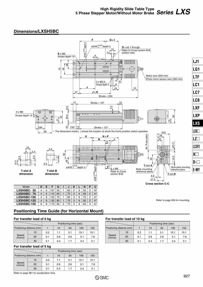
For transfer load of 0 kgPositioning time (sec)
Positioning distance (mm)
Speed(mm/s)
10
20
30
1
0.2
0.1
0.1
10
1.1
0.6
0.4
50
5.1
2.6
1.7
100
10.1
5.1
3.4
150
15.1
7.6
5.1
For transfer load of 10 kg
For transfer load of 5 kgPositioning time (sec)
Positioning distance (mm)
Speed(mm/s)
10
20
30
1
0.2
0.1
0.1
10
1.1
0.6
0.4
50
5.1
2.6
1.7
150
15.1
7.6
5.1
100
10.1
5.1
3.4
Positioning time (sec)
Positioning distance (mm)
Speed(mm/s)
10
20
30
1
0.2
0.1
0.1
10
1.1
0.6
0.4
50
5.1
2.6
1.7
100
10.1
5.1
3.4
150
15.1
7.6
5.1
C
L x M6C
Refer to Crosssection C-C.
T-slot Adimension
T-slot Bdimension
T-slot Aø4H9
+0.030 0 depth 4
Body mounting reference plane
6.5
6.5
3.3
5.8
13
1 ±0
.2(ø
5.1)
36: T
-slo
t pitc
h
20
28
5
4H9+ 0
.030
0de
pth
4
15(5)
0.5
46.5
13 15
3.5
2 x M6
E x M5
thread depth 4
27 19
6
38
58
52 58
76 46
Stroke + 220
2525
8
10
32 x M2.5
36
U
(52)28
T-slot B
Work piece mountingreference plane
27.5
Cross section C-C
10.5
4 5.5
10
6.5
39
(39)
thread depth 13
Motor wire (300 mm)Photo micro sensor wire (300 mm)
D x ø5.1 throughRefer to Cross section C-C,bottom view.
ø5H9+0.030 0 depth 5
5H9
+ 0.0
30 0
dept
h 5
J
thread depth 10
27 J x K
N
Stroke + 127
Stroke + 127
N x P
F G x I
[18]∗
∗ The dimension inside [ ] shows the location at which the home position switch operates.
Model
LXSH5BC- 50LXSH5BC- 75LXSH5BC-100LXSH5BC-125LXSH5BC-150
D44446
E66888
F107112122132112
G5565758565
I11112
J6575657075
K22333
L66668
N5565758565
P22223
U5247474747
107.5
Refer to page 959 for mounting.
Refer to page 961 for acceleration time.
Series LXSHigh Rigidity Slide Table Type5 Phase Stepper Motor/Without Motor Brake
Dimensions/LXSH5BC
Positioning Time Guide (for Horizontal Mount)
927
LJ1
LG1
LTF
LC1
LC7
LC8
LXF
LXP
LXS
LC6�
LZ�
LC3F2
X�
D-�
E-MY
P0910-P0941-E.qxd 10.12.15 11:50 AM Page 927
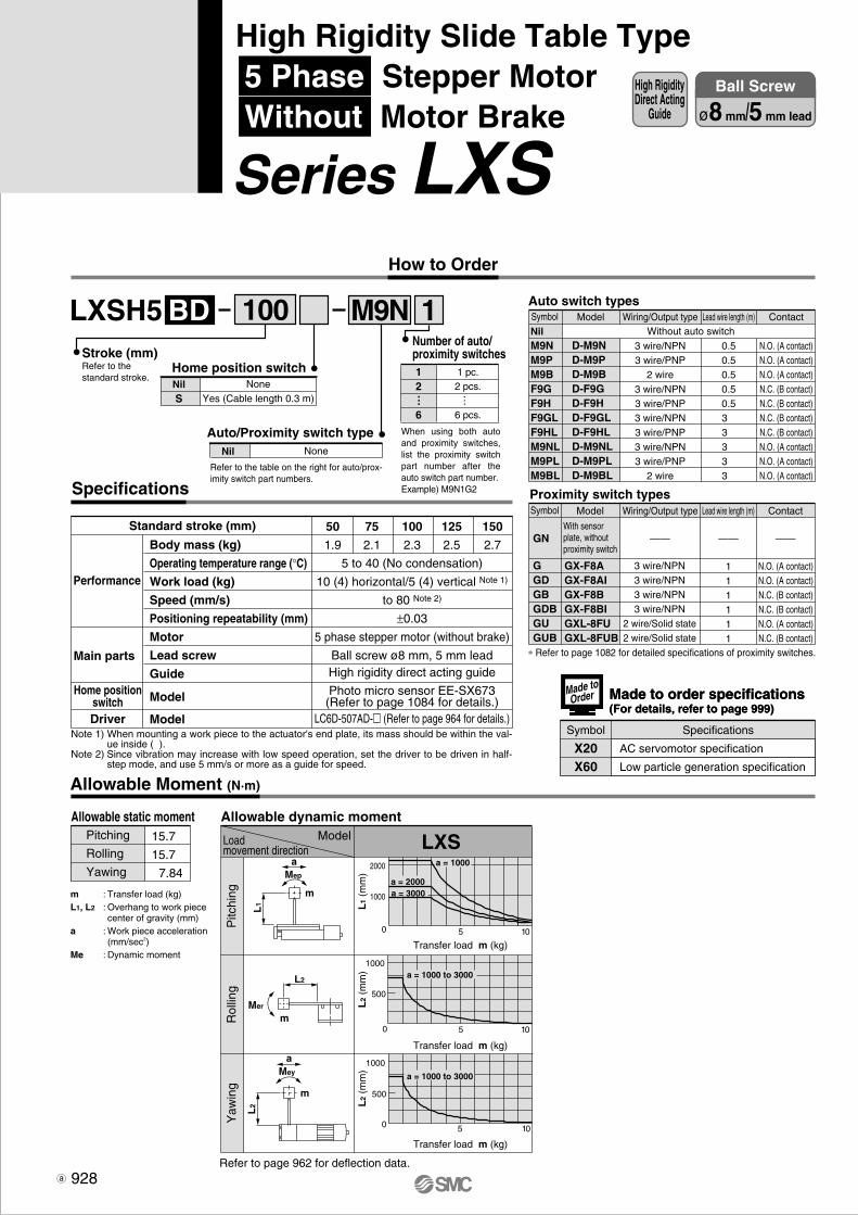
LXSH5 1BD
LXS2000
1000
5 100
5 100
5 100
500
1000
500
1000
a = 1000
a = 2000a = 3000
a = 1000 to 3000
a = 1000 to 3000
aMep
L2
Mer
L2
Mey
L1
m
m
m
a
M9N100
How to Order
Stroke (mm)Refer to the standard stroke.
NoneYes (Cable length 0.3 m)
NilS
Home position switch
NoneNil
Auto/Proximity switch type
Refer to the table on the right for auto/prox-imity switch part numbers.
12
6
Number of auto/proximity switches
1 pc.2 pcs.
6 pcs.
When using both auto and proximity switches, list the proximity switch part number after the auto switch part number.Example) M9N1G2
… …
Auto switch types
NilM9NM9PM9BF9GF9HF9GLF9HLM9NLM9PLM9BL
D-M9ND-M9PD-M9BD-F9GD-F9HD-F9GLD-F9HLD-M9NLD-M9PLD-M9BL
Wiring/Output type
3 wire/NPN3 wire/PNP
2 wire3 wire/NPN3 wire/PNP3 wire/NPN3 wire/PNP3 wire/NPN3 wire/PNP
2 wire
Lead wire length (m)
0.50.50.50.50.53 3 3 3 3
Contact
N.O. (A contact)N.O. (A contact)N.O. (A contact)N.C. (B contact)N.C. (B contact)N.C. (B contact)N.C. (B contact)N.O. (A contact)N.O. (A contact)N.O. (A contact)
Proximity switch typesSymbol
GGDGBGDBGUGUB
GN
GX-F8AGX-F8AIGX-F8BGX-F8BIGXL-8FUGXL-8FUB
3 wire/NPN3 wire/NPN3 wire/NPN3 wire/NPN
2 wire/Solid state2 wire/Solid state
111111
N.O. (A contact)N.O. (A contact)N.C. (B contact)N.C. (B contact)N.O. (A contact)N.C. (B contact)
∗ Refer to page 1082 for detailed specifications of proximity switches.
Without auto switchModelSymbol
Model Wiring/Output type Lead wire length (m) Contact
——————50
1.9
75
2.1
100
2.3
125
2.5
150
2.7
Specifications
Body mass (kg)
Operating temperature range (°C)
Work load (kg)
Speed (mm/s)
Positioning repeatability (mm)
Motor
Lead screw
Guide
Model
Model
5 to 40 (No condensation)
10 (4) horizontal/5 (4) vertical Note 1)
to 80 Note 2)
±0.03
5 phase stepper motor (without brake)
Ball screw ø8 mm, 5 mm leadHigh rigidity direct acting guide
LC6D-507AD-� (Refer to page 964 for details.)
Performance
Main parts
Home positionswitchDriver
Standard stroke (mm)
Allowable Moment (N·m)
Allowable static moment Allowable dynamic moment
Refer to page 962 for deflection data.
ModelLoadmovement direction
Pitc
hing
Rol
ling
Yaw
ing
Transfer load m (kg)
Transfer load m (kg)
Transfer load m (kg)
L1
(mm
)L
2 (m
m)
L2
(mm
)
Pitching
Rolling
Yawing
15.7
15.7
7.84
m : Transfer load (kg)L1, L2 : Overhang to work piece
center of gravity (mm)a : Work piece acceleration
(mm/sec2)Me : Dynamic moment
Photo micro sensor EE-SX673(Refer to page 1084 for details.)
Made to order specifications(For details, refer to page 999)
Symbol Specifications/Description
X20X60
Made toOrder Made to order specifications
(For details, refer to page 999)
Symbol Specifications
AC servomotor specification
Low particle generation specification
X20X60
Made toOrder
With sensor plate, without proximity switch
928
High RigidityDirect Acting
Guide
Ball Screw
ø8 mm/5 mm lead
High Rigidity Slide Table Type 5 Phase Stepper Motor Without Motor Brake
Series LXS
Note 1) When mounting a work piece to the actuator's end plate, its mass should be within the val-ue inside ( ).
Note 2) Since vibration may increase with low speed operation, set the driver to be driven in half-step mode, and use 5 mm/s or more as a guide for speed.

For transfer load of 0 kgPositioning time (sec)
Positioning distance (mm)
Speed(mm/s)
10
40
80
1
0.2
0.1
0.1
10
1.1
0.3
0.2
50
5.1
1.3
0.7
100
10.1
2.6
1.3
150
15.1
3.8
1.9
For transfer load of 10 kg
For transfer load of 5 kgPositioning time (sec)
Positioning distance (mm)
Speed(mm/s)
10
40
80
1
0.2
0.1
0.1
10
1.1
0.3
0.2
50
5.1
1.3
0.7
150
15.1
3.8
2.0
100
10.1
2.6
1.3
Positioning time (sec)
Positioning distance (mm)
Speed(mm/s)
10
40
80
1
0.2
0.1
0.1
10
1.1
0.3
0.2
50
5.1
1.3
0.7
100
10.1
2.6
1.3
150
15.1
3.8
2.0
C
L x M6C
Refer to Crosssection C-C.
T-slot Adimension
T-slot Bdimension
T-slot Aø4H9
+0.030 0 depth 4 Body mounting
reference plane
6.5
6.5
3.3
5.8
13
1 ±0
.2(ø
5.1)
36: T
-slo
t pitc
h
20
28
5
4H9
+ 0.0
300
dept
h 4
15(5)
0.5
46.5
13 15
3.5
2 x M6
E x M5
thread depth 4
27 19
6
38
58
52 58
76 46
Stroke + 220
2525
8
10
32 x M2.5
36
U
(52)28
T-slot B
Work piece mountingreference plane
27.5
Cross section C-C
10.5
4 5.5
10
6.5
39
(39)
thread depth 13
Motor wire (300 mm)Photo micro sensor wire (300 mm)
D x ø5.1 throughRefer to Cross section C-C, bottom view.
ø5H9+0.030
0 depth 5
5H9
+ 0.0
300
dept
h 5
J
thread depth 10
27 J x K
N
Stroke + 127
Stroke + 127
N x P
F G x I
[18]∗
∗ The dimension inside [ ] shows the location at which the home position switch operates.
Model
LXSH5BD- 50LXSH5BD- 75LXSH5BD-100LXSH5BD-125LXSH5BD-150
D44446
E66888
F107112122132112
G5565758565
I11112
J6575657075
K22333
L66668
N5565758565
P22223
U5247474747
10
7.5
Refer to page 959 for mounting.
Refer to page 961 for acceleration time.
Dimensions/LXSH5BD
Positioning Time Guide (for Horizontal Mount)
Series LXSHigh Rigidity Slide Table Type5 Phase Stepper Motor/Without Motor Brake
929
LJ1
LG1
LTF
LC1
LC7
LC8
LXF
LXP
LXS
LC6�
LZ�
LC3F2
X�
D-�
E-MY
P0910-P0941-E.qxd 10.12.15 11:50 AM Page 929
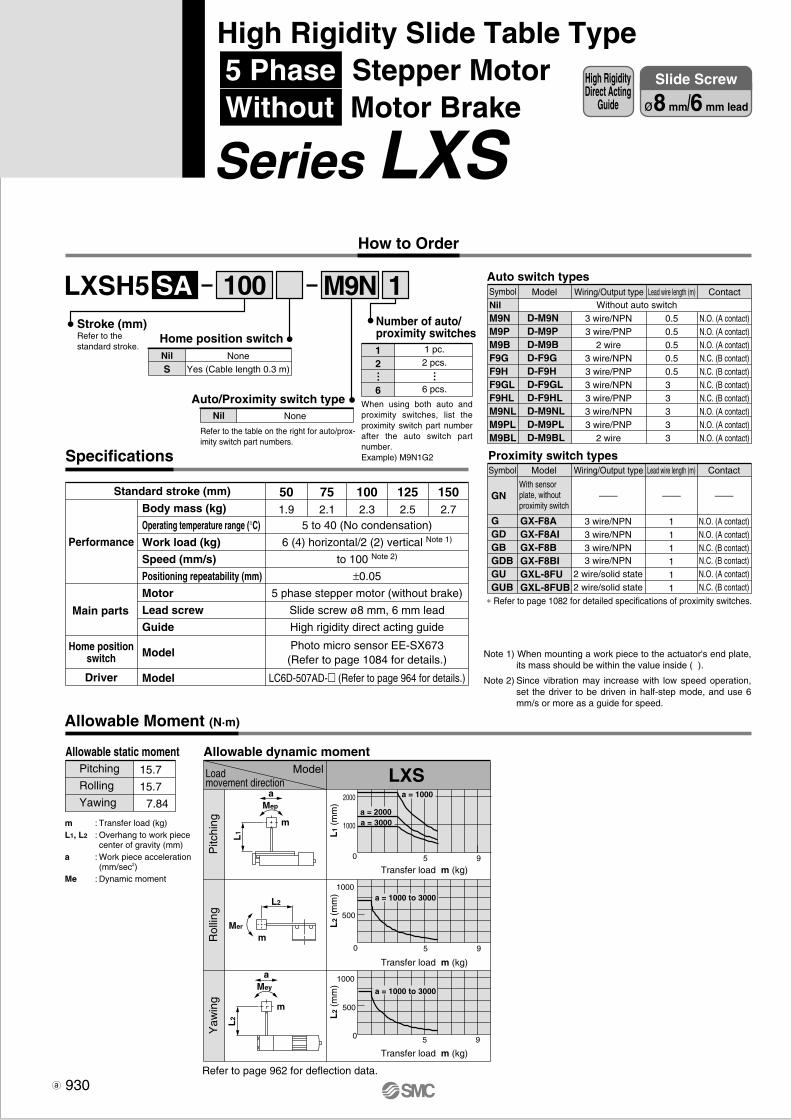
2000
1000
5 90
5 90
5 90
500
1000
500
1000
a = 1000
a = 2000a = 3000
a = 1000 to 3000
a = 1000 to 3000
LXSH5 1SA
LXSa
Mep
L2
Mer
L2
Mey
L1
m
m
m
a
M9N
Body mass (kg)
Operating temperature range (°C)
Work load (kg)
Speed (mm/s)
Positioning repeatability (mm)
Motor
Lead screw
Guide
Model
Model
Performance
Main parts
5 to 40 (No condensation)
6 (4) horizontal/2 (2) vertical Note 1)
to 100 Note 2)
±0.05
5 phase stepper motor (without brake)
Slide screw ø8 mm, 6 mm lead
High rigidity direct acting guide
Photo micro sensor EE-SX673(Refer to page 1084 for details.)
LC6D-507AD-� (Refer to page 964 for details.)
501.9
752.1
1002.3
1252.5
1502.7
100
1 pc.2 pcs.
6 pcs.
12
6
Number of auto/proximity switches
… …
When using both auto and proximity switches, list the proximity switch part number after the auto switch part number.Example) M9N1G2
Auto switch types
NilM9NM9PM9BF9GF9HF9GLF9HLM9NLM9PLM9BL
D-M9ND-M9PD-M9BD-F9GD-F9HD-F9GLD-F9HLD-M9NLD-M9PLD-M9BL
Model
3 wire/NPN3 wire/PNP
2 wire3 wire/NPN3 wire/PNP3 wire/NPN3 wire/PNP3 wire/NPN3 wire/PNP
2 wire
0.50.50.50.50.53 3 3 3 3
N.O. (A contact)N.O. (A contact)N.O. (A contact)N.C. (B contact)N.C. (B contact)N.C. (B contact)N.C. (B contact)N.O. (A contact)N.O. (A contact)N.O. (A contact)
Proximity switch typesSymbol
GGDGBGDBGUGUB
GN
GX-F8AGX-F8AIGX-F8BGX-F8BIGXL-8FUGXL-8FUB
Model Wiring/Output type
3 wire/NPN3 wire/NPN3 wire/NPN3 wire/NPN
2 wire/solid state2 wire/solid state
Lead wire length (m)
111111
Contact
——————
N.O. (A contact)N.O. (A contact)N.C. (B contact)N.C. (B contact)N.O. (A contact)N.C. (B contact)
With sensor plate, without proximity switch
∗ Refer to page 1082 for detailed specifications of proximity switches.
Without auto switchSymbol Wiring/Output type Lead wire length (m) Contact
Specifications
Standard stroke (mm)
Note 1) When mounting a work piece to the actuator's end plate, its mass should be within the value inside ( ).
Note 2) Since vibration may increase with low speed operation, set the driver to be driven in half-step mode, and use 6 mm/s or more as a guide for speed.
Allowable Moment (N·m)
Allowable static moment Allowable dynamic moment
Refer to page 962 for deflection data.
ModelLoadmovement direction
Pitc
hing
Rol
ling
Yaw
ing
Transfer load m (kg)
Transfer load m (kg)
Transfer load m (kg)
L1
(mm
)L
2 (m
m)
L2
(mm
)
Pitching
Rolling
Yawing
15.7
15.7
7.84
m : Transfer load (kg)L1, L2 : Overhang to work piece
center of gravity (mm)a : Work piece acceleration
(mm/sec2)Me : Dynamic moment
930
High RigidityDirect Acting
Guide
Slide Screw
ø8 mm/6 mm lead
High Rigidity Slide Table Type 5 Phase Stepper Motor Without Motor Brake
Series LXS How to Order
Stroke (mm)Refer to the standard stroke.
NoneYes (Cable length 0.3 m)
NilS
Home position switch
NoneNil
Auto/Proximity switch type
Refer to the table on the right for auto/prox-imity switch part numbers.
Home positionswitch
Driver

For transfer load of 0 kgPositioning time (sec)
Positioning distance (mm)
Speed(mm/s)
10
50
100
1
0.2
0.1
0.1
10
1.1
0.3
0.2
50
5.1
1.1
0.6
100
10.1
2.1
1.1
150
15.1
3.1
1.6
For transfer load of 6 kg
For transfer load of 3 kgPositioning time (sec)
Positioning distance (mm)
Speed(mm/s)
10
50
100
1
0.2
0.1
0.1
10
1.1
0.3
0.2
50
5.1
1.1
0.6
150
15.1
3.1
1.6
100
10.1
2.1
1.1
Positioning time (sec)
Positioning distance (mm)
Speed(mm/s)
10
50
100
1
0.2
0.1
0.1
10
1.1
0.3
0.2
50
5.1
1.1
0.6
100
10.1
2.1
1.1
150
15.1
3.1
1.6
C
L x M6C
Refer to Crosssection C-C.
T-slot Adimension
T-slot Bdimension
T-slot Aø4H9
+0.030 0 depth 4 Body mounting
reference plane
6.5
6.5
3.3
5.8
13
1 ±0
.2(ø
5.1)
36: T
-slo
t pitc
h
20
28
5
4H9
+ 0.0
30 0
dept
h 4
15(5)
0.5
46.5
13 15
3.5
2 x M6
E x M5
thread depth 4
27 19
6
38
58
52 58
76 46
Stroke + 220
2525
8
10
32 x M2.5
36
U
(52)28
T-slot B
Work piece mountingreference plane
27.5
Cross section C-C
10.5
4 5.5
10
6.5
39
(39)
thread depth 13
Motor wire (300 mm)Photo micro sensor wire (300 mm)
D x ø5.1 throughRefer to Cross section C-C, bottom view.
ø5H9+0.030 0 depth 5
5H9
+ 0.0
30 0
dept
h 5
J
thread depth 10
27 J x K
N
Stroke + 127
Stroke + 127
N x P
F G x I
[18]∗
∗ The dimension inside [ ] shows the location at which the home position switch operates.
Model
LXSH5SA- 50LXSH5SA- 75LXSH5SA-100LXSH5SA-125LXSH5SA-150
D44446
E66888
F107112122132112
G5565758565
I11112
J6575657075
K22333
L66668
N5565758565
P22223
U5247474747
107.5
Refer to page 959 for mounting.
Refer to page 960 for acceleration time.
931
Dimensions/LXSH5SA
Positioning Time Guide (for Horizontal Mount)
Series LXSHigh Rigidity Slide Table Type5 Phase Stepper Motor/Without Motor Brake
LJ1
LG1
LTF
LC1
LC7
LC8
LXF
LXP
LXS
LC6�
LZ�
LC3F2
X�
D-�
E-MY
P0910-P0941-E.qxd 10.12.15 11:50 AM Page 931

2000
1000
5 90
5 90
5 90
500
1000
500
1000
a = 1000
a = 2000a = 3000
a = 1000 to 3000
a = 1000 to 3000
100LXSH5 1SB
LXSa
Mep
L2
Mer
L2
Mey
L1
m
m
m
a
M9N
NoneYes (Cable length 0.3 m)
NilS
Home position switch
NoneNil
Auto/Proximity switch type
Refer to the table on the right for auto/prox-imity switch part numbers.
1 pc.2 pcs.
6 pcs.
12
6
Number of auto/proximity switches
… …
When using both auto and proximity switches, list the proximity switch part number after the auto switch part number.Example) M9N1G2
Auto switch types
NilM9NM9PM9BF9GF9HF9GLF9HLM9NLM9PLM9BL
D-M9ND-M9PD-M9BD-F9GD-F9HD-F9GLD-F9HLD-M9NLD-M9PLD-M9BL
Model
3 wire/NPN3 wire/PNP
2 wire3 wire/NPN3 wire/PNP3 wire/NPN3 wire/PNP3 wire/NPN3 wire/PNP
2 wire
0.50.50.50.50.53 3 3 3 3
N.O. (A contact)N.O. (A contact)N.O. (A contact)N.C. (B contact)N.C. (B contact)N.C. (B contact)N.C. (B contact)N.O. (A contact)N.O. (A contact)N.O. (A contact)
Proximity switch typesSymbol
GGDGBGDBGUGUB
GN
GX-F8AGX-F8AIGX-F8BGX-F8BIGXL-8FUGXL-8FUB
Model Wiring/Output type
3 wire/NPN3 wire/NPN3 wire/NPN3 wire/NPN
2 wire/solid state2 wire/solid state
Lead wire length (m)
111111
Contact
——————
N.O. (A contact)N.O. (A contact)N.C. (B contact)N.C. (B contact)N.O. (A contact)N.C. (B contact)
With sensor plate, without proximity switch
∗ Refer to page 1082 for detailed specifications of proximity switches.
Without auto switchSymbol Wiring/Output type Lead wire length (m) Contact
50
1.9
75
2.1
100
2.3
125
2.5
150
2.7
Specifications
Body mass (kg)
Operating temperature range (°C)
Work load (kg)
Speed (mm/s)
Positioning repeatability (mm)
Motor
Lead screw
Guide
Model
Model
5 to 40 (No condensation)
3 (3) horizontal/1 (1) vertical
to 200 Note 1)
±0.05
5 phase stepper motor (without brake)
Slide screw ø8 mm, 12 mm lead
High rigidity direct acting guide
Photo micro sensor EE-SX673(Refer to page 1084 for details.)
LC6D-507AD-� (Refer to page 964 for details.)
Performance
Main parts
Home position switch
Standard stroke (mm)
Note 1) Since vibration may increase with low speed operation, set the driver to be driven in half-step mode, and use 12 mm/s or more as a guide for speed.
Allowable Moment (N·m)
Allowable static moment Allowable dynamic moment
Refer to page 962 for deflection data.
ModelLoadmovement direction
Pitc
hing
Rol
ling
Yaw
ing
Transfer load m (kg)
Transfer load m (kg)
Transfer load m (kg)
L1
(mm
)L
2 (m
m)
L2
(mm
)
Pitching
Rolling
Yawing
15.7
15.7
7.84
m : Transfer load (kg)L1, L2 : Overhang to work piece
center of gravity (mm)a : Work piece acceleration
(mm/sec2)Me : Dynamic moment
Driver
932
High RigidityDirect Acting
Guide
Slide Screw
ø8 mm/12 mm lead
High Rigidity Slide Table Type 5 Phase Stepper Motor Without Motor Brake
Series LXS How to Order
Stroke (mm)Refer to the standard stroke.

For transfer load of 0 kgPositioning time (sec)
Positioning distance (mm)
Speed(mm/s)
50
100
200
1
0.1
0.1
0.1
10
0.3
0.2
0.1
50
1.1
0.6
0.3
100
2.1
1.1
0.6
150
3.1
1.6
0.8
For transfer load of 3 kg
For transfer load of 1.5 kgPositioning time (sec)
Positioning distance (mm)
Speed(mm/s)
50
100
200
1
0.1
0.1
0.1
10
0.3
0.2
0.1
50
1.1
0.6
0.3
150
3.1
1.6
0.8
100
2.1
1.1
0.6
Positioning time (sec)
Positioning distance (mm)
Speed(mm/s)
50
100
200
1
0.1
0.1
0.1
10
0.3
0.2
0.2
50
1.1
0.6
0.4
100
2.1
1.1
0.6
150
3.1
1.6
0.9
C
L x M6C
Refer to Crosssection C-C.
T-slot Adimension
T-slot Bdimension
T-slot Aø4H9
+0.030 0 depth 4 Body mounting
reference plane
6.5
6.5
3.3
5.8
13
1 ±0
.2(ø
5.1)
36: T
-slo
t pitc
h
20
28
5
4H9
+ 0.0
30 0
dept
h 4
15(5)
0.5
46.5
13 15
3.5
2 x M6
E x M5
thread depth 4
27
19
6
38
58
52 58
76 46
Stroke + 220
2525
8
10
32 x M2.5
36
U
(52)28
T-slot B
Work piece mountingreference plane
27.5
Cross section C-C
10.5
4 5.5
10
6.5
39
(39)
thread depth 13
Motor wire (300 mm)Photo micro sensor wire (300 mm)
D x ø5.1 throughRefer to Cross section C-C, bottom view.
ø5H9+0.030 0 depth 5
5H9
+ 0.0
30 0
dept
h 5
J
thread depth 10
27 J x K
N
Stroke + 127
Stroke + 127
N x P
F G x I
[18]∗
∗ The dimension inside [ ] shows the location at which the home position switch operates.
Model
LXSH5SB- 50LXSH5SB- 75LXSH5SB-100LXSH5SB-125LXSH5SB-150
D44446
E66888
F107112122132112
G5565758565
I11112
J6575657075
K22333
L66668
N5565758565
P22223
U5247474747
107.5
Refer to page 959 for mounting.
Refer to page 960 for acceleration time.
933
Dimensions/LXSH5SB
Positioning Time Guide (for Horizontal Mount)
Series LXSHigh Rigidity Slide Table Type5 Phase Stepper Motor/Without Motor Brake
LJ1
LG1
LTF
LC1
LC7
LC8
LXF
LXP
LXS
LC6�
LZ�
LC3F2
X�
D-�
E-MY
P0910-P0941-E.qxd 10.12.15 11:50 AM Page 933

100LXSH5 1BBC M9N
LXS
m
L2
1000
500
5 90
5 90
1000
500a = 1000 to 3000
a = 1000 to 3000
Mep
L1
Mey a
am
Stroke (mm)Refer to the standard stroke.
NoneYes (Cable length 0.3 m)
NilS
Home position switch
NoneNil
Auto/Proximity switch type
Refer to the table on the right for auto/prox-imity switch part numbers.
1 pc.2 pcs.
6 pcs.
12
6
Number of auto/proximity switches
… …
When using both auto and proximity switches, list the prox-imity switch part number after the auto switch part number.Example) M9N1G2
Auto switch types
NilM9NM9PM9BF9GF9HF9GLF9HLM9NLM9PLM9BL
D-M9ND-M9PD-M9BD-F9GD-F9HD-F9GLD-F9HLD-M9NLD-M9PLD-M9BL
Model
3 wire/NPN3 wire/PNP
2 wire3 wire/NPN3 wire/PNP3 wire/NPN3 wire/PNP3 wire/NPN3 wire/PNP
2 wire
0.50.50.50.50.53 3 3 3 3
N.O. (A contact)N.O. (A contact)N.O. (A contact)N.C. (B contact)N.C. (B contact)N.C. (B contact)N.C. (B contact)N.O. (A contact)N.O. (A contact)N.O. (A contact)
Proximity switch typesSymbol
GGDGBGDBGUGUB
GN
GX-F8AGX-F8AIGX-F8BGX-F8BIGXL-8FUGXL-8FUB
Model Wiring/Output type
3 wire/NPN3 wire/NPN3 wire/NPN3 wire/NPN
2 wire/solid state2 wire/solid state
Lead wire length (m)
111111
Contact
——————
N.O. (A contact)N.O. (A contact)N.C. (B contact)N.C. (B contact)N.O. (A contact)N.C. (B contact)
∗ Refer to page 1082 for detailed specifications of proximity switches.
Without auto switchSymbol Wiring/Output type Lead wire length (m) Contact
50
2.1
75
2.3
100
2.5
125
2.7
150
2.9
Specifications
Performance
Main parts
Home position switch
Body mass (kg)
Operating temperature range (°C)
Work load (kg)
Speed (mm/s)
Positioning repeatability (mm)
Motor
Lead screw
Guide
Model
Model
Standard stroke (mm)
Electromagneticbrake
ModelStatic torque (N·m)
Rated voltage (V)
Power consumption (W)
5 to 40 (No condensation)
10 (4) horizontal/5 (4) vertical Note 1)
to 30 Note 2)
±0.035 phase stepper motor (with brake)
Ball screw ø8 mm, 2 mm lead
High rigidity direct acting guideDe-energized operating type
0.1 or more
24 DC ±5%5
Photo micro sensor EE-SX673(Refer to page 1084 for details.)
LC6D-507AD-� (Refer to page 964 for details.)
Note 1) When mounting a work piece to the actuator's end plate, its mass should be within the value inside ( ).
Note 2) Since vibration may increase with low speed operation, set the driver to be driven in half-step mode, and use 2 mm/s or more as a guide for speed.
Allowable Moment (N·m)
Allowable dynamic momentModelLoad
movement direction
Pitc
hing
Yaw
ing
Transfer load m (kg)
Transfer load m (kg)
L1
(mm
)L
2 (m
m)
Refer to page 962 for deflection data.
Allowable static moment
Pitching
Yawing
15.7
7.84
m : Transfer load (kg)L1, L2 : Overhang to work piece
center of gravity (mm)a : Work piece acceleration
(mm/sec2)Me : Dynamic moment
Driver
934
High RigidityDirect Acting
Guide
Ball Screw
ø8 mm/2 mm lead
High Rigidity Slide Table Type 5 Phase Stepper Motor With Motor Brake
Series LXS
Made to order specifications(For details, refer to page 999)
Symbol Specifications
AC servomotor specification
Low particle generation specification
X20X60
Made toOrder
With sensor plate, without proximity switch
How to Order
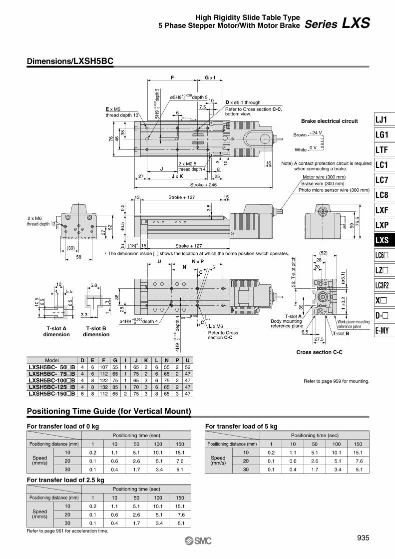
For transfer load of 0 kg For transfer load of 5 kg
For transfer load of 2.5 kgPositioning time (sec)
Positioning distance (mm)
Speed(mm/s)
10
20
30
1
0.2
0.1
0.1
10
1.1
0.6
0.4
50
5.1
2.6
1.7
150
15.1
7.6
5.1
100
10.1
5.1
3.4
Positioning time (sec)
Positioning distance (mm)
Speed(mm/s)
10
20
30
1
0.2
0.1
0.1
10
1.1
0.6
0.4
50
5.1
2.6
1.7
150
15.1
7.6
5.1
100
10.1
5.1
3.4
Positioning time (sec)
Positioning distance (mm)
Speed(mm/s)
10
20
30
1
0.2
0.1
0.1
10
1.1
0.6
0.4
50
5.1
2.6
1.7
150
15.1
7.6
5.1
100
10.1
5.1
3.4
D x ø5.1 through
Refer to Cross section C-C, bottom view.
ø5H9+0.030 0 depth 5
5H9
+ 0.0
30 0
dept
h 5
thread depth 10Brake electrical circuit
Note) A contact protection circuit is required when connecting a brake.
+24 V
0 V
59
16
75.5
E x M5
384676
27 25
8
1032 x M2.5
6
Stroke + 246
Stroke + 12715(5)
0.5
46.5
13 15Stroke + 127
3.5
C
C
L x M6ø4H9 +0.030
0 depth 4
28
N x P5
4H9
+0.
030
0de
pth
4
U
Refer to Crosssection C-C.
36
T-slot Adimension
T-slot Bdimension
6.5
6.5
3.3
5.8
13
Cross section C-C
10.5
4 5.5
10
T-slot ABody mountingreference plane
1 ±0
.2(ø
5.1)
36: T
-slo
t pitc
h
20
(52)
28
T-slot B
Work piece mountingreference plane
27.5
6.5
39
thread depth 4
2 x M6
27
58
52
(39)
thread depth 13
J x KJ
N
Brown
White
F G x I
Motor wire (300 mm)Brake wire (300 mm)
Photo micro sensor wire (300 mm)
[18]∗
∗ The dimension inside [ ] shows the location at which the home position switch operates.
Model
LXSH5BC- 50�BLXSH5BC- 75�BLXSH5BC-100�BLXSH5BC-125�BLXSH5BC-150�B
D44446
E66888
F107112122132112
G5565758565
I11112
J6575657075
K22333
L66668
N5565758565
P22223
U5247474747
107.5
Refer to page 959 for mounting.
Refer to page 961 for acceleration time.
935
Series LXSHigh Rigidity Slide Table Type5 Phase Stepper Motor/With Motor Brake
Dimensions/LXSH5BC
Positioning Time Guide (for Vertical Mount)
LJ1
LG1
LTF
LC1
LC7
LC8
LXF
LXP
LXS
LC6�
LZ�
LC3F2
X�
D-�
E-MY
P0910-P0941-E.qxd 10.12.15 11:50 AM Page 935

100LXSH5 1BBD
Specifications
M9N
LXS
m
L2
1000
500
5 90
5 90
1000
500a = 1000 to 3000
a = 1000 to 3000
Mep
L1
Mey a
am
High RigidityDirect Acting
Guide
Ball Screw
ø8 mm/5 mm lead
High Rigidity Slide Table Type 5 Phase Stepper Motor With Motor Brake
Series LXS How to Order
Stroke (mm)Refer to the standard stroke.
NoneYes (Cable length 0.3 m)
NilS
Home position switch
NoneNil
Auto/Proximity switch type
Refer to the table on the right for auto/prox-imity switch part numbers.
1 pc.2 pcs.
6 pcs.
12
6
Number of auto/proximity switches
… …
When using both auto and proximity switches, list the proximity switch part number after the auto switch part number.Example) M9N1G2
Auto switch types
NilM9NM9PM9BF9GF9HF9GLF9HLM9NLM9PLM9BL
D-M9ND-M9PD-M9BD-F9GD-F9HD-F9GLD-F9HLD-M9NLD-M9PLD-M9BL
Model
3 wire/NPN3 wire/PNP
2 wire3 wire/NPN3 wire/PNP3 wire/NPN3 wire/PNP3 wire/NPN3 wire/PNP
2 wire
0.50.50.50.50.53 3 3 3 3
N.O. (A contact)N.O. (A contact)N.O. (A contact)N.C. (B contact)N.C. (B contact)N.C. (B contact)N.C. (B contact)N.O. (A contact)N.O. (A contact)N.O. (A contact)
Proximity switch typesSymbol
GGDGBGDBGUGUB
GN
GX-F8AGX-F8AIGX-F8BGX-F8BIGXL-8FUGXL-8FUB
Model Wiring/Output type
3 wire/NPN3 wire/NPN3 wire/NPN3 wire/NPN
2 wire/solid state2 wire/solid state
Lead wire length (m)
111111
Contact
——————
N.O. (A contact)N.O. (A contact)N.C. (B contact)N.C. (B contact)N.O. (A contact)N.C. (B contact)
∗ Refer to page 1082 for detailed specifications of proximity switches.
Without auto switchSymbol Wiring/Output type Lead wire length (m) Contact
50
2.1
75
2.3
100
2.5
125
2.7
150
2.9
Performance
Main parts
Body mass (kg)
Operating temperature range (°C)
Work load (kg)
Speed (mm/s)
Positioning repeatability (mm)
Motor
Lead screw
Guide
Model
Model
Standard stroke (mm)
Electromagneticbrake
Model
Static torque (N·m)
Rated voltage (V)Power consumption (W)
5 to 40 (No condensation)
10 (4) horizontal/5 (4) vertical Note 1)
to 80 Note 2)
±0.03
5 phase stepper motor (with brake)
Ball screw ø8 mm, 5 mm lead
High rigidity direct acting guide
De-energized operating type
0.1 or more
24 DC ±5%
5
Note 1) When mounting a work piece to the actuator's end plate, its mass should be within the value inside ( ).
Note 2) Since vibration may increase with low speed operation, set the driver to be driven in half-step mode, and use 5 mm/s or more as a guide for speed.
Allowable Moment (N·m)
Allowable dynamic momentModelLoad
movement direction
Pitc
hing
Yaw
ing
Transfer load m (kg)
Transfer load m (kg)
L1
(mm
)L
2 (m
m)
Refer to page 962 for deflection data.
Allowable static moment
Pitching
Yawing
15.7
7.84
m : Transfer load (kg)L1, L2 : Overhang to work piece
center of gravity (mm)a : Work piece acceleration
(mm/sec2)Me : Dynamic moment
Made to order specifications(For details, refer to page 999)
Symbol Specifications
AC servomotor specification
Low particle generation specification
X20X60
Made toOrder
With sensor plate, without proximity switch
Home position switch
Driver
Photo micro sensor EE-SX673(Refer to page 1084 for details.)
LC6D-507AD-� (Refer to page 964 for details.)
936

For transfer load of 0 kg For transfer load of 5 kg
For transfer load of 2.5 kgPositioning time (sec)
Positioning distance (mm)
Speed(mm/s)
10
40
80
1
0.2
0.1
0.1
10
1.1
0.3
0.2
50
5.1
1.3
0.7
150
15.1
3.8
2.0
100
10.1
2.6
1.3
Positioning time (sec)
Positioning distance (mm)
Speed(mm/s)
10
40
80
1
0.2
0.1
0.1
10
1.1
0.3
0.2
50
5.1
1.3
0.7
150
15.1
3.8
1.9
100
10.1
2.6
1.3
Positioning time (sec)
Positioning distance (mm)
Speed(mm/s)
10
40
80
1
0.2
0.1
0.1
10
1.1
0.3
0.2
50
5.1
1.3
0.7
150
15.1
3.8
2.0
100
10.1
2.6
1.3
D x ø5.1 through
Refer to Cross section C-C, bottom view.
ø5H9+0.030 0 depth 5
5H9
+ 0.0
30 0
dept
h 5
thread depth 10Brake electrical circuit
Note) A contact protection circuit is required when connecting a brake.
+24 V
0 V
59
16
75.5
E x M5
384676
27 25
8
1032 x M2.5
6
Stroke + 246
Stroke + 12715(5)
0.5
46.5
13 15Stroke + 127
3.5
C
C
L x M6
ø4H9+0.030 0 depth 4
28
N x P5
4H9
+0.
030
0de
pth
4
U
Refer to Crosssection C-C.
36
T-slot Adimension
T-slot Bdimension
6.5
6.5
3.3
5.8
13
Cross section C-C
10.5
4 5.5
10
T-slot ABody mountingreference plane
1 ±0
.2(ø
5.1)
36: T
-slo
t pitc
h
20
(52)
28
T-slot B
Work piece mountingreference plane
27.5
6.5
39
thread depth 4
2 x M6
27
58
52
(39)
thread depth 13
J x KJ
N
Brown
White
F G x I
Motor wire (300 mm)Brake wire (300 mm)
Photo micro sensor wire (300 mm)
[18]∗
∗ The dimension inside [ ] shows the location at which the home position switch operates.
Model
LXSH5BD- 50�BLXSH5BD- 75�BLXSH5BD-100�BLXSH5BD-125�BLXSH5BD-150�B
D44446
E66888
F107112122132112
G5565758565
I11112
J6575657075
K22333
L66668
N5565758565
P22223
U5247474747
107.5
Refer to page 959 for mounting.
Refer to page 961 for acceleration time.
937
Dimensions/LXSH5BD
Positioning Time Guide (for Vertical Mount)
Series LXSHigh Rigidity Slide Table Type5 Phase Stepper Motor/With Motor Brake
LJ1
LG1
LTF
LC1
LC7
LC8
LXF
LXP
LXS
LC6�
LZ�
LC3F2
X�
D-�
E-MY
P0910-P0941-E.qxd 10.12.15 11:50 AM Page 937

100LXSH5 1BSA M9N
1000
500
5 90
5 90
1000
500a = 1000 to 3000
a = 1000 to 3000
LXS
m
L2
Mep
L1
Mey a
am
Stroke (mm)Refer to the standard stroke.
NoneYes (Cable length 0.3 m)
NilS
Home position switch
NoneNil
Auto/Proximity switch type
Refer to the table on the right for auto/prox-imity switch part numbers.
1 pc.2 pcs.
6 pcs.
12
6
Number of auto/proximity switches
… …
When using both auto and proximity switches, list the proximity switch part number after the auto switch part number.Example) M9N1G2
Auto switch types
NilM9NM9PM9BF9GF9HF9GLF9HLM9NLM9PLM9BL
D-M9ND-M9PD-M9BD-F9GD-F9HD-F9GLD-F9HLD-M9NLD-M9PLD-M9BL
Model
3 wire/NPN3 wire/PNP
2 wire3 wire/NPN3 wire/PNP3 wire/NPN3 wire/PNP3 wire/NPN3 wire/PNP
2 wire
0.50.50.50.50.53 3 3 3 3
N.O. (A contact)N.O. (A contact)N.O. (A contact)N.C. (B contact)N.C. (B contact)N.C. (B contact)N.C. (B contact)N.O. (A contact)N.O. (A contact)N.O. (A contact)
Proximity switch typesSymbol
GGDGBGDBGUGUB
GN
GX-F8AGX-F8AIGX-F8BGX-F8BIGXL-8FUGXL-8FUB
Model Wiring/Output type
3 wire/NPN3 wire/NPN3 wire/NPN3 wire/NPN
2 wire/solid state2 wire/solid state
Lead wire length (m)
111111
Contact
——————
N.O. (A contact)N.O. (A contact)N.C. (B contact)N.C. (B contact)N.O. (A contact)N.C. (B contact)
∗ Refer to page 1082 for detailed specifications of proximity switches.
Without auto switchSymbol Wiring/Output type Lead wire length (m) Contact
50
2.1
75
2.3
100
2.5
125
2.7
150
2.9
Specifications
Performance
Main parts
Body mass (kg)
Operating temperature range (°C)
Work load (kg)
Speed (mm/s)Positioning repeatability (mm)
Motor
Lead screw
Guide
Model
Model
Standard stroke (mm)
Electromagneticbrake
Model
Static torque (N·m)
Rated voltage (V)
Power consumption (W)
5 to 40 (No condensation)
6 (4) horizontal/2 (2) vertical Note 1)
to 100 Note 2)
±0.05
5 phase stepper motor (with brake)
Slide screw ø8 mm, 6 mm lead
High rigidity direct acting guide
De-energized operating type
0.1 or more
24 DC ±5%
5
Photo micro sensor EE-SX673(Refer to page 1084 for details.)
LC6D-507AD-� (Refer to page 964 for details.)
Home position switch
Driver
Note 1) When mounting a work piece to the actuator's end plate, its mass should be within the value inside ( ).
Note 2) Since vibration may increase with low speed operation, set the driver to be driven in half-step mode, and use 6 mm/s or more as a guide for speed.
Allowable Moment (N·m)
Allowable dynamic momentModelLoad
movement direction
Pitc
hing
Yaw
ing
Transfer load m (kg)
Transfer load m (kg)
L1
(mm
)L
2 (m
m)
Refer to page 962 for deflection data.
Allowable static moment
Pitching
Yawing
15.7
7.84
m : Transfer load (kg)L1, L2 : Overhang to work piece
center of gravity (mm)a : Work piece acceleration
(mm/sec2)Me : Dynamic moment
With sensor plate, without proximity switch
938
High RigidityDirect Acting
Guide
Slide Screw
ø8 mm/6 mm lead
High Rigidity Slide Table Type 5 Phase Stepper Motor With Motor Brake
Series LXS How to Order
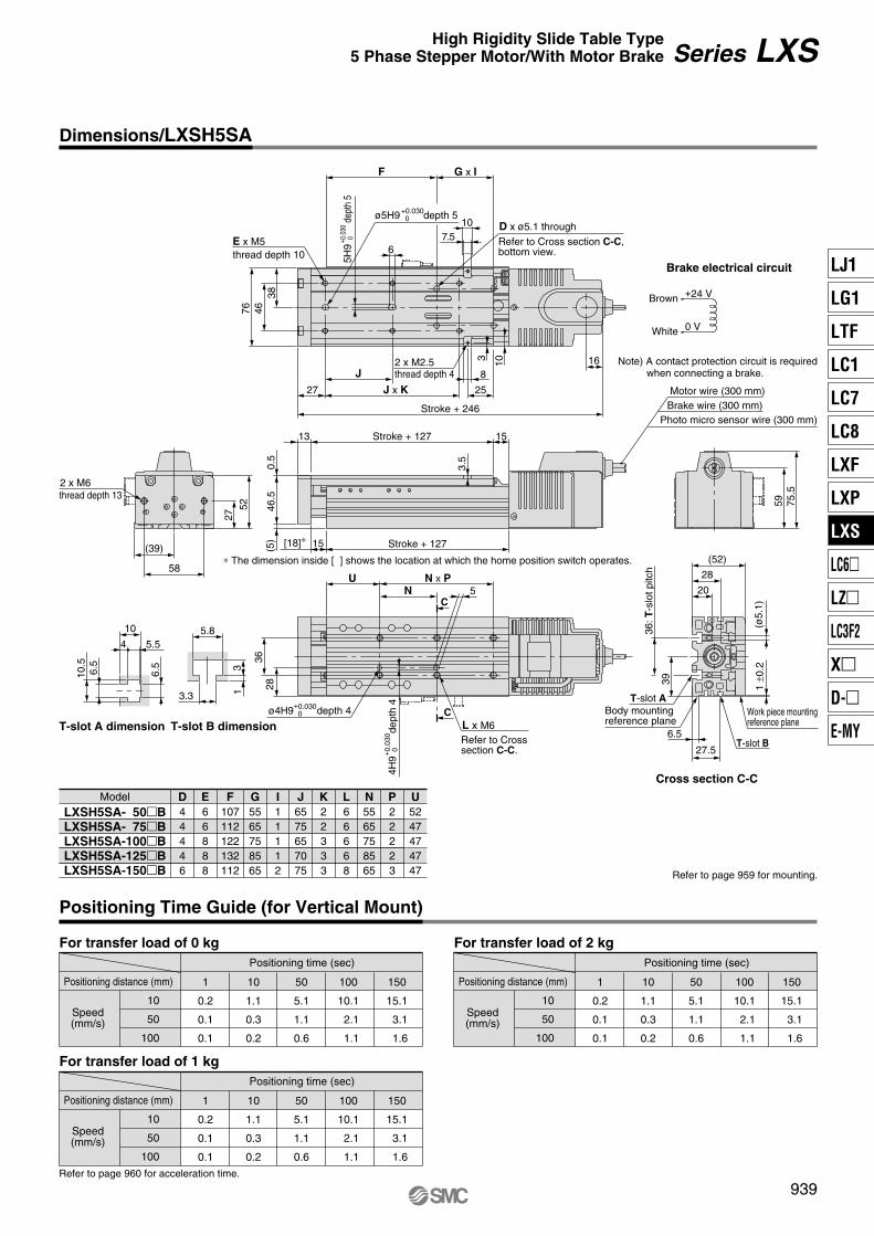
For transfer load of 0 kg For transfer load of 2 kg
For transfer load of 1 kgPositioning time (sec)
Positioning distance (mm)
Speed(mm/s)
10
50
100
1
0.2
0.1
0.1
10
1.1
0.3
0.2
50
5.1
1.1
0.6
150
15.1
3.1
1.6
100
10.1
2.1
1.1
Positioning time (sec)
Positioning distance (mm)
Speed(mm/s)
10
50
100
1
0.2
0.1
0.1
10
1.1
0.3
0.2
50
5.1
1.1
0.6
150
15.1
3.1
1.6
100
10.1
2.1
1.1
Positioning time (sec)
Positioning distance (mm)
Speed(mm/s)
10
50
100
1
0.2
0.1
0.1
10
1.1
0.3
0.2
50
5.1
1.1
0.6
150
15.1
3.1
1.6
100
10.1
2.1
1.1
D x ø5.1 through
Refer to Cross section C-C, bottom view.
ø5H9+0.030 0 depth 5
5H9
+ 0.0
30 0
dept
h 5
thread depth 10
Note) A contact protection circuit is required when connecting a brake.
59
16
75.5
E x M5
384676
27 25
8
1032 x M2.5
6
Stroke + 246
Stroke + 12715(5)
0.5
46.5
13 15Stroke + 127
3.5
C
C
L x M6ø4H9+0.030
0 depth 4
28
N x P5
4H9
+0.
030
0de
pth
4
U
Refer to Crosssection C-C.
36
T-slot A dimension T-slot B dimension
6.5
6.5
3.3
5.8
13
Cross section C-C
10.5
4 5.5
10
T-slot ABody mountingreference plane
1 ±0
.2(ø
5.1)
36: T
-slo
t pitc
h
20
(52)
28
T-slot B
Work piece mountingreference plane
27.5
6.5
39
thread depth 4
2 x M6
27
58
52
(39)
thread depth 13
J x KJ
N
F G x I
Motor wire (300 mm)Brake wire (300 mm)
Photo micro sensor wire (300 mm)
[18]∗
∗ The dimension inside [ ] shows the location at which the home position switch operates.
Model
LXSH5SA- 50�BLXSH5SA- 75�BLXSH5SA-100�BLXSH5SA-125�BLXSH5SA-150�B
D44446
E66888
F107112122132112
G5565758565
I11112
J6575657075
K22333
L66668
N5565758565
P22223
U5247474747
107.5
Refer to page 959 for mounting.
Refer to page 960 for acceleration time.
Brake electrical circuit
+24 V
0 V
Brown
White
939
Series LXSHigh Rigidity Slide Table Type5 Phase Stepper Motor/With Motor Brake
Dimensions/LXSH5SA
Positioning Time Guide (for Vertical Mount)
LJ1
LG1
LTF
LC1
LC7
LC8
LXF
LXP
LXS
LC6�
LZ�
LC3F2
X�
D-�
E-MY
P0910-P0941-E.qxd 10.12.15 11:50 AM Page 939

1000
500
5 90
5 90
1000
500a = 1000 to 3000
a = 1000 to 3000
100LXSH5 1BSB M9N
LXS
m
L2
Mep
L1
Mey a
am
NoneNil
Auto/Proximity switch type
Refer to the table on the right for auto/prox-imity switch part numbers.
1 pc.2 pcs.
6 pcs.
12
6
Number of auto/proximity switches
… …
When using both auto and proximity switches, list the proximity switch part number after the auto switch part number.Example) M9N1G2
Auto switch types
NilM9NM9PM9BF9GF9HF9GLF9HLM9NLM9PLM9BL
D-M9ND-M9PD-M9BD-F9GD-F9HD-F9GLD-F9HLD-M9NLD-M9PLD-M9BL
Model
3 wire/NPN3 wire/PNP
2 wire3 wire/NPN3 wire/PNP3 wire/NPN3 wire/PNP3 wire/NPN3 wire/PNP
2 wire
0.50.50.50.50.53 3 3 3 3
N.O. (A contact)N.O. (A contact)N.O. (A contact)N.C. (B contact)N.C. (B contact)N.C. (B contact)N.C. (B contact)N.O. (A contact)N.O. (A contact)N.O. (A contact)
Proximity switch typesSymbol
GGDGBGDBGUGUB
GN
GX-F8AGX-F8AIGX-F8BGX-F8BIGXL-8FUGXL-8FUB
Model Wiring/Output type
3 wire/NPN3 wire/NPN3 wire/NPN3 wire/NPN
2 wire/solid state2 wire/solid state
Lead wire length (m)
111111
Contact
——————
N.O. (A contact)N.O. (A contact)N.C. (B contact)N.C. (B contact)N.O. (A contact)N.C. (B contact)
∗ Refer to page 1082 for detailed specifications of proximity switches.
Without auto switchSymbol Wiring/Output type Lead wire length (m) Contact
Specifications
50
2.1
75
2.3
100
2.5
125
2.7
150
2.9
Performance
Main parts
Body mass (kg)
Operating temperature range (°C)
Work load (kg)
Speed (mm/s)
Positioning repeatability (mm)
Motor
Lead screw
Guide
Model
Model
Standard stroke (mm)
Electromagneticbrake
Model
Static torque (N·m)
Rated voltage (V)
Power consumption (W)
5 to 40 (No condensation)
3 (3) horizontal/1 (1) vertical Note 1)
to 200 Note 2)
±0.05
5 phase stepper motor (with brake)
Slide screw ø8 mm, 12 mm leadHigh rigidity direct acting guide
De-energized operating type
Photo micro sensor EE-SX673(Refer to page 1084 for details.)
LC6D-507AD-� (Refer to page 964 details.)
24 DC ±5%
5
0.1 or more
Note 1) When mounting a work piece to the actuator's end plate, its mass should be within the value inside ( ).
Note 2) Since vibration may increase with low speed operation, set the driver to be driven in half-step mode, and use 12 mm/s or more as a guide for speed.
Allowable Moment (N·m)
Allowable dynamic momentModelLoad
movement direction
Pitc
hing
Yaw
ing
Transfer load m (kg)
Transfer load m (kg)
L1
(mm
)L
2 (m
m)
Refer to page 962 for deflection data.
Allowable static moment
Pitching
Yawing
15.7
7.84
m : Transfer load (kg)L1, L2 : Overhang to work piece
center of gravity (mm)a : Work piece acceleration
(mm/sec2)Me : Dynamic moment
Home positionswitch
Driver
940
High RigidityDirect Acting
Guide
Slide Screw
ø8 mm/12 mm lead
High Rigidity Slide Table Type 5 Phase Stepper Motor With Motor Brake
Series LXS How to Order
Stroke (mm)
NoneYes (Cable length 0.3 m)
NilS
Home position switchRefer to the standard stroke.
With sensor plate, without proximity switch
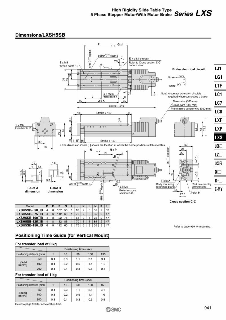
For transfer load of 0 kg
For transfer load of 1 kgPositioning time (sec)
Positioning distance (mm)
Speed(mm/s)
50
100
200
1
0.1
0.1
0.1
10
0.3
0.2
0.1
50
1.1
0.6
0.3
150
3.1
1.6
0.8
100
2.1
1.1
0.6
Positioning time (sec)
Positioning distance (mm)
Speed(mm/s)
50
100
200
1
0.1
0.1
0.1
10
0.3
0.2
0.1
50
1.1
0.6
0.3
150
3.1
1.6
0.8
100
2.1
1.1
0.6
D x ø5.1 through
Refer to Cross section C-C, bottom view.
ø5H9+0.030 0 depth 5
5H9
+ 0.0
30 0
dept
h 5
thread depth 10
Note) A contact protection circuit is required when connecting a brake.
59
16
75.5
E x M5
384676
27 25
8
1032 x M2.5
6
Stroke + 246
Stroke + 12715(5)
0.5
46.5
13 15Stroke + 127
3.5
C
C
L x M6ø4H9+0.030
0 depth 4
28
N x P5
4H9
+0.
030
0de
pth
4
U
Refer to cross section C-C.
36
T-slot Adimension
T-slot Bdimension
6.5
6.5
3.3
5.8
13
Cross section C-C
10.5
4 5.5
10
T-slot A
1 ±0
.2(ø
5.1)
36: T
-slo
t pitc
h
20
(52)
28
T-slot B
Work piece mountingreference plane
27.5
6.5
39
thread depth 4
2 x M6
27
58
52
(39)
thread depth 13
J x KJ
N
F G x I
Motor wire (300 mm)Brake wire (300 mm)
Photo micro sensor wire (300 mm)
[18]∗
∗ The dimension inside [ ] shows the location at which the home position switch operates.
Model
LXSH5SB- 50�BLXSH5SB- 75�BLXSH5SB-100�BLXSH5SB-125�BLXSH5SB-150�B
D44446
E66888
F107112122132112
G5565758565
I11112
J6575657075
K22333
L66668
N5565758565
P22223
U5247474747
107.5
Refer to page 959 for mounting.
Refer to page 960 for acceleration time.
Brake electrical circuit
+24 V
0 V
Brown
White
Body mountingreference plane
941
Series LXSHigh Rigidity Slide Table Type5 Phase Stepper Motor/With Motor Brake
Dimensions/LXSH5SB
Positioning Time Guide (for Vertical Mount)
LJ1
LG1
LTF
LC1
LC7
LC8
LXF
LXP
LXS
LC6�
LZ�
LC3F2
X�
D-�
E-MY
P0910-P0941-E.qxd 10.12.15 11:50 AM Page 941
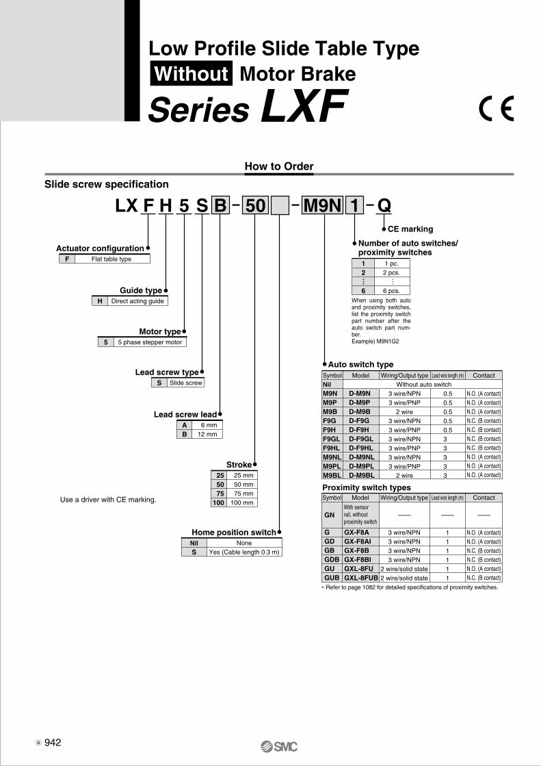
6 mm12 mm
AB
Lead screw lead
Flat table typeF
Actuator configuration
Direct acting guideH
Guide type
5 phase stepper motor5
Motor type
Slide screwS
Lead screw type
LX F H 5 S
1 pc.2 pcs.
6 pcs.
12
6
Number of auto switches/proximity switches
1
25 mm50 mm75 mm
100 mm
255075
100
Stroke
Home position switch
B 50
… …
CE marking
Q
Use a driver with CE marking.
Slide screw specification
M9N
When using both auto and proximity switches, list the proximity switch part number after the auto switch part num-ber.Example) M9N1G2
NoneYes (Cable length 0.3 m)
NilS
Auto switch typeSymbolNilM9NM9PM9BF9GF9HF9GLF9HLM9NLM9PLM9BL
D-M9ND-M9PD-M9BD-F9GD-F9HD-F9GLD-F9HLD-M9NLD-M9PLD-M9BL
Model Wiring/Output type
3 wire/NPN3 wire/PNP
2 wire3 wire/NPN3 wire/PNP3 wire/NPN3 wire/PNP3 wire/NPN3 wire/PNP
2 wire
Lead wire length (m)
0.50.50.50.50.53 3 3 3 3
Contact
N.O. (A contact)N.O. (A contact)N.O. (A contact)N.C. (B contact)N.C. (B contact)N.C. (B contact)N.C. (B contact)N.O. (A contact)N.O. (A contact)N.O. (A contact)
Without auto switch
Proximity switch typesSymbol
GGDGBGDBGUGUB
GN
GX-F8AGX-F8AIGX-F8BGX-F8BIGXL-8FUGXL-8FUB
Model Wiring/Output type
3 wire/NPN3 wire/NPN3 wire/NPN3 wire/NPN
2 wire/solid state2 wire/solid state
Lead wire length (m)
111111
Contact
——————
N.O. (A contact)N.O. (A contact)N.C. (B contact)N.C. (B contact)N.O. (A contact)N.C. (B contact)
∗ Refer to page 1082 for detailed specifications of proximity switches.
With sensor rail, without proximity switch
How to Order
942
Low Profile Slide Table Type Without Motor Brake
Series LXF

Slide screw ø8 mm
±0.05
6
3 to 100
3 (2)
12
6 to 200
2 (2)
Direct acting guide
5 to 40 (No condensation)
LC6D-507AD-Q, LC6D-507AD-P1-X316 (Refer to page 964 for details.)
Motor
Lead screw (mm)
Positioning repeatability (mm)
Lead (mm)
Speed (mm/s) Note 1)
Work load (kg) Note 2)
Guide type
Operating temperature range (°C)
Home position switch
Applicable driver
CE marking accessories
5 phase stepper motor (without brake)
Photo micro sensor EE-SX672(Refer to page 1084 for details.)
Holding plate: MB1(1 pc.), Phillips countersunk head screw M3 x 6 l (1 pc.)Phillips binding head screw: M3 x 4 l (2 pcs.), Toothed lock washer M3 (2 pcs.)Binding band: T18S (1 pc.)
LXFH5S
ModelStandard stroke (mm)
(kg)
250.8
501.0
751.1
1001.2
For basic specifications such as allowable moment, refer to the "Standard" pages for equivalent products listed on Features pages 462 and 463.
Specifications
Mass
Horizontal
Note 1) Since vibration may increase with low speed operation, set the driver to be driven in half-step mode, and use 6 mm/s or more for 6 mm lead, and 12 mm/s or more for 12 mm lead as a guide for speed.
Note 2) When mounting a work piece to the actuator's end plate, its mass should be within the value inside ( ).
943
Series LXFLow Profile Slide Table TypeWithout Motor Brake
LJ1
LG1
LTF
LC1
LC7
LC8
LXF
LXP
LXS
LC6�
LZ�
LC3F2
X�
D-�
E-MY
P0942-P0945-E.qxd 10.12.15 11:51 AM Page 943
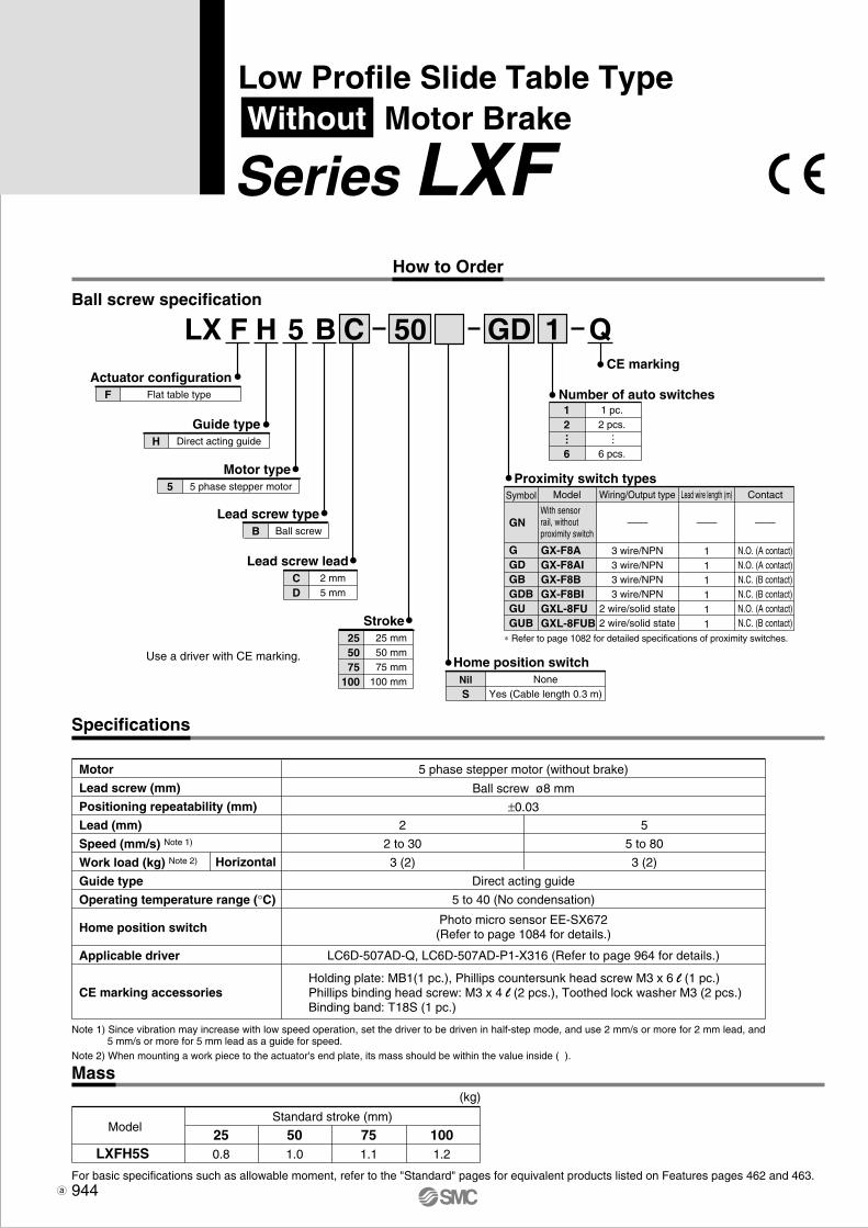
NoneYes (Cable length 0.3 m)
NilS
Home position switch
2 mm5 mm
CD
Lead screw lead
Flat table typeF
Actuator configuration
Direct acting guideH
Guide type
5 phase stepper motor5
Motor type
Ball screwB
Lead screw type
LX F H 5 B
1 pc.2 pcs.
6 pcs.
12
6
Number of auto switches
1
25 mm50 mm75 mm
100 mm
255075
100
Stroke
C 50 GD
Ball screw ø8 mm
±0.03
2
2 to 30
3 (2)
5
5 to 80
3 (2)
Direct acting guide
5 to 40 (No condensation)
LC6D-507AD-Q, LC6D-507AD-P1-X316 (Refer to page 964 for details.)
Motor
Lead screw (mm)
Positioning repeatability (mm)
Lead (mm)
Speed (mm/s) Note 1)
Work load (kg) Note 2)
Guide type
Operating temperature range (°C)
Home position switch
Applicable driver
CE marking accessories
5 phase stepper motor (without brake)
… …
Horizontal
Photo micro sensor EE-SX672(Refer to page 1084 for details.)
Holding plate: MB1(1 pc.), Phillips countersunk head screw M3 x 6 l (1 pc.)Phillips binding head screw: M3 x 4 l (2 pcs.), Toothed lock washer M3 (2 pcs.)Binding band: T18S (1 pc.)
LXFH5S
ModelStandard stroke (mm)
(kg)
250.8
501.0
751.1
1001.2
Note 1) Since vibration may increase with low speed operation, set the driver to be driven in half-step mode, and use 2 mm/s or more for 2 mm lead, and 5 mm/s or more for 5 mm lead as a guide for speed.
Note 2) When mounting a work piece to the actuator's end plate, its mass should be within the value inside ( ).
Use a driver with CE marking.
Ball screw specification
Specifications
Mass
CE marking
Q
Proximity switch typesSymbol
GGDGBGDBGUGUB
GN
GX-F8AGX-F8AIGX-F8BGX-F8BIGXL-8FUGXL-8FUB
Model Wiring/Output type
3 wire/NPN3 wire/NPN3 wire/NPN3 wire/NPN
2 wire/solid state2 wire/solid state
Lead wire length (m)
111111
Contact
——————
N.O. (A contact)N.O. (A contact)N.C. (B contact)N.C. (B contact)N.O. (A contact)N.C. (B contact)
∗ Refer to page 1082 for detailed specifications of proximity switches.
For basic specifications such as allowable moment, refer to the "Standard" pages for equivalent products listed on Features pages 462 and 463.
With sensor rail, without proximity switch
How to Order
944
Low Profile Slide Table Type Without Motor Brake
Series LXF

ModelLXFH5S�- 25LXFH5S�- 50LXFH5S�- 75LXFH5S�-100
D4466
E60909090
F30606060
G(50)(50)100100
Phillips countersunk head screw (included)
Binding band (included)
Toothed lock washer (included)
Crimping terminal
M3 x 6 l
Phillips binding head screw (included)
M3 x 4 l
Holding plate(included)
D x M4 x 0.7 (for work piece mounting)
2 x M4 x 0.7thread depth 9
ø5H9+0.030 0 depth 5
ø5H9+0.030 0 depth 5
2 x M3thread depth 5
6
59 F
29.5
321
241
Stroke + 126
10
31
5H9
+0.
030
0de
pth
5
10 (39.5) E
17.5
222535
28
50
G
6
58
(6)
8 5H9
dept
h 5
+0.
030
0
Stroke + 135
10.5
5 Stroke + 113
2.5
18.5
1020
(5)
627212
(5.5)10
31
(3.5)
1 ±0
.2
25(4)
30.5
136
4 x M5 x 0.8 (for body mounting) thread depth 8
Motor wire(300 mm)
Photo micro sensor wire(300 mm)
4 x ø8
(11.5) 38 E
∗∗ The dimension inside [ ] shows the location at which the home position switch operates.
1.5 [5.5]∗∗
12
(15)
10.5
5.8
8
5 3
T-slot dimension (2/1)
3.3
(5) 2 x M2.5 x 0.45 depth 2
Label
2 x M3 x 0.5Effective thread depth 4 (PE terminal)∗
Effective thread depth 4 (PE terminal)M3 x 0.5
80.5
32 5
25.5
∗ When using a PE terminal, use accessories included as shown on the left.
Refer to page 957 for mounting.
945
Series LXFLow Profile Slide Table TypeWithout Motor Brake
Dimensions/LXFH5
LJ1
LG1
LTF
LC1
LC7
LC8
LXF
LXP
LXS
LC6�
LZ�
LC3F2
X�
D-�
E-MY
P0942-P0945-E.qxd 10.12.15 11:51 AM Page 945
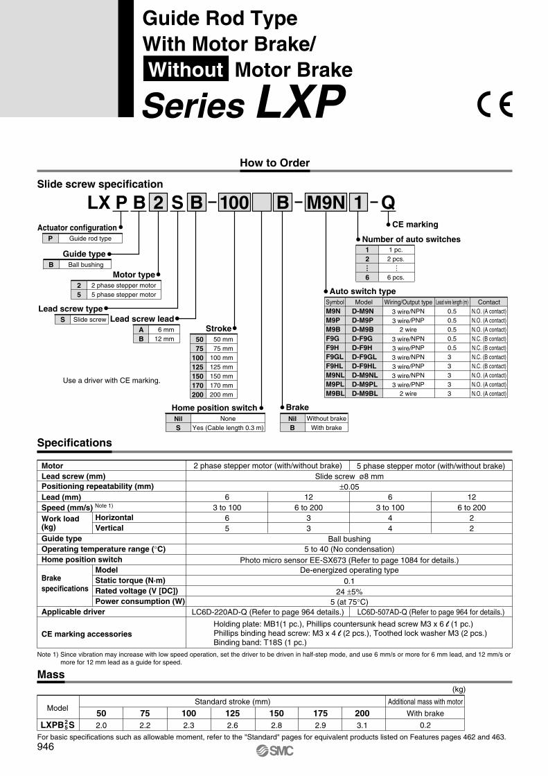
Slide screw ø8 mm±0.05
63 to 100
65
126 to 200
33
63 to 100
44
126 to 200
22
LC6D-220AD-Q (Refer to page 964 details.) LC6D-507AD-Q (Refer to page 964 for details.)
Ball bushing5 to 40 (No condensation)
De-energized operating type0.1
24 ±5%5 (at 75°C)
MotorLead screw (mm)Positioning repeatability (mm)Lead (mm)Speed (mm/s) Note 1)
Work load(kg)Guide typeOperating temperature range (°C)Home position switch
Brakespecifications
Applicable driver
CE marking accessories
2 phase stepper motor (with/without brake) 5 phase stepper motor (with/without brake)
HorizontalVertical
ModelStatic torque (N·m)Rated voltage (V [DC])Power consumption (W)
Photo micro sensor EE-SX673 (Refer to page 1084 for details.)
Holding plate: MB1(1 pc.), Phillips countersunk head screw M3 x 6 l (1 pc.)Phillips binding head screw: M3 x 4 l (2 pcs.), Toothed lock washer M3 (2 pcs.)Binding band: T18S (1 pc.)
LXPB S
ModelAdditional mass with motor
With brake
0.2
Standard stroke (mm)
(kg)
502.0
752.2
1002.3
1252.6
1502.8
1752.9
2003.12
5
Note 1) Since vibration may increase with low speed operation, set the driver to be driven in half-step mode, and use 6 mm/s or more for 6 mm lead, and 12 mm/s or more for 12 mm lead as a guide for speed.
For basic specifications such as allowable moment, refer to the "Standard" pages for equivalent products listed on Features pages 462 and 463.
Slide screw specification
NoneYes (Cable length 0.3 m)
NilS
Home position switch
6 mm12 mm
AB
Lead screw lead
Guide rod typeP
Actuator configuration
Ball bushingB
Guide type
2 phase stepper motor5 phase stepper motor
25
Motor type
Slide screwS
Lead screw type
LX P B 2 S
Number of auto switches
1
50 mm75 mm
100 mm125 mm150 mm170 mm200 mm
5075
100125150170200
Stroke
B 100 M9NCE marking
Q
Without brakeWith brake
NilB
Brake
B
Auto switch type
Use a driver with CE marking.
SymbolM9NM9PM9BF9GF9HF9GLF9HLM9NLM9PLM9BL
D-M9ND-M9PD-M9BD-F9GD-F9HD-F9GLD-F9HLD-M9NLD-M9PLD-M9BL
Model Wiring/Output type
3 wire/NPN
3 wire/PNP2 wire
3 wire/NPN
3 wire/PNP
3 wire/NPN
3 wire/PNP
3 wire/NPN
3 wire/PNP2 wire
Lead wire length (m)0.50.50.50.50.53 3 3 3 3
ContactN.O. (A contact)N.O. (A contact)N.O. (A contact)N.C. (B contact)N.C. (B contact)N.C. (B contact)N.C. (B contact)N.O. (A contact)N.O. (A contact)N.O. (A contact)
1 pc.2 pcs.
6 pcs.
12
6
… …
Specifications
Mass
Guide Rod TypeWith Motor Brake/ Without Motor Brake
Series LXP How to Order
946
P0946-P0948-E.qxd 10.12.15 11:51 AM Page 946
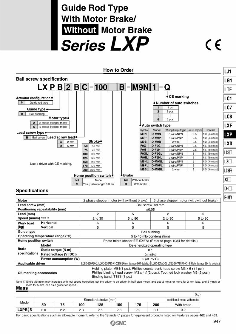
Ball screw ø8 mm±0.05
22 to 30
65
55 to 80
65
22 to 30
65
55 to 80
65
LC6D-220AD-Q, LC6D-220AD-P1-X316 (Refer to page 964 details.) LC6D-507AD-Q, LC6D-507AD-P1-X316 (Refer to page 964 for details.)
Ball bushing5 to 40 (No condensation)
De-energized operating type0.1
24 ±5%5 (at 75°C)
MotorLead screw (mm)Positioning repeatability (mm)Lead (mm)Speed (mm/s) Note 1)
Work load(kg)Guide typeOperating temperature range (°C)Home position switch
Brakespecifications
Applicable driver
CE marking accessories
2 phase stepper motor (with/without brake) 5 phase stepper motor (with/without brake)
HorizontalVertical
ModelStatic torque (N·m)Rated voltage (V [DC])Power consumption (W)
Photo micro sensor EE-SX673 (Refer to page 1084 for details.)
Holding plate: MB1(1 pc.), Phillips countersunk head screw M3 x 6 l (1 pc.)Phillips binding head screw: M3 x 4 l (2 pcs.), Toothed lock washer M3 (2 pcs.)Binding band: T18S (1 pc.)
LXPB S
ModelAdditional mass with motor
With brake
0.2
Standard stroke (mm)
(kg)
502.0
752.2
1002.3
1252.6
1502.8
1752.9
2003.12
5
Note 1) Since vibration may increase with low speed operation, set the driver to be driven in half-step mode, and use 2 mm/s or more for 2 mm lead, and 5 mm/s or more for 5 mm lead as a guide for speed.
Ball screw specification
NoneYes (Cable length 0.3 m)
NilS
Home position switch
2 mm5 mm
CD
Lead screw lead
Guide rod typeP
Actuator configuration
Ball bushingB
Guide type
2 phase stepper motor5 phase stepper motor
25
Motor type
Ball screwB
Lead screw type
LX P B 2 B
Number of auto switches
1
50 mm75 mm
100 mm125 mm150 mm170 mm200 mm
5075
100125150170200
Stroke
C 100 M9N
Without brakeWith brake
NilB
Brake
B
Auto switch type
Use a driver with CE marking.
SymbolM9NM9PM9BF9GF9HF9GLF9HLM9NLM9PLM9BL
D-M9ND-M9PD-M9BD-F9GD-F9HD-F9GLD-F9HLD-M9NLD-M9PLD-M9BL
Model Wiring/Output type
3 wire/NPN
3 wire/PNP2 wire
3 wire/NPN
3 wire/PNP
3 wire/NPN
3 wire/PNP
3 wire/NPN
3 wire/PNP2 wire
Lead wire length (m)0.50.50.50.50.53 3 3 3 3
ContactN.O. (A contact)N.O. (A contact)N.O. (A contact)N.C. (B contact)N.C. (B contact)N.C. (B contact)N.C. (B contact)N.O. (A contact)N.O. (A contact)N.O. (A contact)
1 pc.2 pcs.
6 pcs.
12
6
… …
Specifications
Mass
CE marking
Q
For basic specifications such as allowable moment, refer to the "Standard" pages for equivalent products listed on Features pages 462 and 463.
How to Order
947
Guide Rod TypeWith Motor Brake/ Without Motor Brake
Series LXP LJ1
LG1
LTF
LC1
LC7
LC8
LXF
LXP
LXS
LC6�
LZ�
LC3F2
X�
D-�
E-MY
P0946-P0948-E.qxd 10.12.15 11:51 AM Page 947

ModelLXPB�S�- 50LXPB�S�- 75LXPB�S�-100LXPB�S�-125LXPB�S�-150LXPB�S�-175LXPB�S�-200
D
44
120
E
52
90
(mm)
4 x M6 x 1
4 x M6 x 1
Cross section BB
C section
Section C detail
B
B
18
30
30.5
3464
10
10 [16.5]∗∗10
36
4.5
ø4H
9+0.
030
0
4H9+0.030 0
38
4.5
9Section F
50
1
7.5
12
43
5.5
5.4
8.4
4 x
ø9.
54
x ø
5.6+
0.1
0
49
30 D
34
E
ø4H9 +0.030 0depth 6
D
With brake
Without brake
(Scale: 2/1)
Photo micro sensor wire (300 mm)
Motor wire (300 mm)
4 x M6 x 1 depth 10C section
ø4H9+0.
030
0
dept
h 6 26
6373
3478919447
.5
21.5
Stroke + 181Stroke + 198
Stroke + 104Stroke + 121
∗∗ The dimension inside [ ] shows the location at which the home position switch operates.
Effective thread depth 4
Label
2 x M3 x 0.5 (PE terminal)∗
Effective thread depth 7
M3 x 0.5 (PE terminal)∗
33 7.5
Phillips countersunk head screw (included)
Binding band (included)
Toothed lock washer (included)
Crimping terminal
M3 x 6 l
M3 x 4 l
Holding plate(included)
Phillips binding head screw(included)
∗ When using a PE terminal, use accessories included as shown above.
When two dimensions are shown, the top dimensions is for 50 to 75 and 100 mm stokes, andthe bottom dimension is for 125, 150, 175, and 200 mm strokes.
Refer to page 958 for mounting.
Section F detail(Scale: 2/1)
523.56
1
12
7888
40.5
Stroke + 216 (Stroke: 50 to 100)Stroke + 233 (Stroke: 125 to 200)
Dimensions/LXPB 25
948
Series LXP
P0946-P0948-E.qxd 10.12.15 11:51 AM Page 948

6 mm12 mm
AB
Lead screw lead
Slide screwS
Lead screw type
50 mm75 mm
100 mm125 mm150 mm
5075
100125150
Stroke
Use a driver with CE marking.
1 pc.2 pcs.
6 pcs.
12
6
Number of auto switches/proximity switches
Home position switch
… …
When using both auto and proximity switches, list the proximity switch part number after the auto switch part number.Example) M9N1G2
NoneYes (Cable length 0.3 m)
NilS
Brake
Auto switch typesSymbolNilM9NM9PM9BF9GF9HF9GLF9HLM9NLM9PLM9BL
D-M9ND-M9PD-M9BD-F9GD-F9HD-F9GLD-F9HLD-M9NLD-M9PLD-M9BL
Model Wiring/Output type
3 wire/NPN3 wire/PNP
2 wire3 wire/NPN3 wire/PNP3 wire/NPN3 wire/PNP3 wire/NPN3 wire/PNP
2 wire
Lead wire length (m)
0.50.50.50.50.53 3 3 3 3
Contact
N.O. (A contact)N.O. (A contact)N.O. (A contact)N.C. (B contact)N.C. (B contact)N.C. (B contact)N.C. (B contact)
N.O. (A contact)N.O. (A contact)N.O. (A contact)
Without auto switch
Slide screw specification
LX S H 2 S 1B 100 M9NB
Slide table typeS
Actuator configuration
Without brakeWith brake
NilB
CE marking
Q
Proximity switch typesSymbol
GGDGBGDBGUGUB
GN
GX-F8AGX-F8AIGX-F8BGX-F8BIGXL-8FUGXL-8FUB
Model Wiring/Output type
3 wire/NPN3 wire/NPN3 wire/NPN3 wire/NPN
2 wire/solid state2 wire/solid state
Lead wire length (m)
111111
Contact
——————
N.O. (A contact)N.O. (A contact)N.C. (B contact)N.C. (B contact)
N.O. (A contact)N.C. (B contact)
∗ Refer to page 1082 for detailed specifications of proximity switches.
Direct acting guideH
Guide type
2 phase stepper motor5 phase stepper motor
25
Motor type
With sensor plate, without proximity switch
How to Order
949
High Rigidity Slide Table TypeWith Motor Brake/ Without Motor Brake
Series LXS LJ1
LG1
LTF
LC1
LC7
LXF
LXP
LXS
LC6�
LZ�
LC3F2
X�
D-�
E-MY

Specifications
63 to 100
9 (4)4 (4)
126 to 2004.5 (4)2 (2)
63 to 100
6 (4)2 (2)
126 to 200
3 (3)1 (1)
LC6D-220AD-Q (Refer to page 964 for details.) LC6D-507AD-Q (Refer to page 964 for details.)
High rigidity direct acting guide5 to 40 (No condensation)
De-energized operating type0.1
24 ±5%5 (at 75°C)
±0.05
Photo micro sensor EE-SX673 (Refer to page 1084 for details.)
Holding plate: MB1 (1 pc.), Phillips countersunk head screw: M3 x 6 l (1 pc.)Phillips binding head screw: M3 x 4 l (2 pcs.), Toothed lock washer M3 (2 pcs.)Binding band: T18S (1 pc.)
Note 1) Since vibration may increase with low speed operation, set the driver to be driven in half-step mode, and use 6 mm/s or more for 6 mm lead, and 12 mm/s or more for 12 mm lead as a guide for speed.Note 2) When mounting a work piece to the actuator's end plate, its mass should be within the value inside ( ).
Mass
LXSH S
ModelAdditional mass with motor
With brake
0.2
Standard stroke (mm)
(kg)
501.9
752.1
1002.3
1252.5
1502.72
5
HorizontalVertical
ModelStatic torque (N·m)Rated voltage (V [DC])Power consumption (W)
MotorLead screw (mm)Positioning repeatability (mm)Lead (mm)Speed (mm/s) Note1)
Work load (kg) Note 2)
Guide typeOperating temperature range (°C)
Home position switch (optional)
Brake specifications
Applicable driverPositioning repeatability (mm)
CE marking accessories
Slide screw ø8 mm±0.05
2 phase stepper motor (with/without brake) 5 phase stepper motor (with/without brake)
For basic specifications such as allowable moment, refer to the "Standard" pages for equivalent products listed on Features pages 462 and 463.
950
Series LXS
P0950-P0953-E.qxd 10.12.15 11:51 AM Page 950
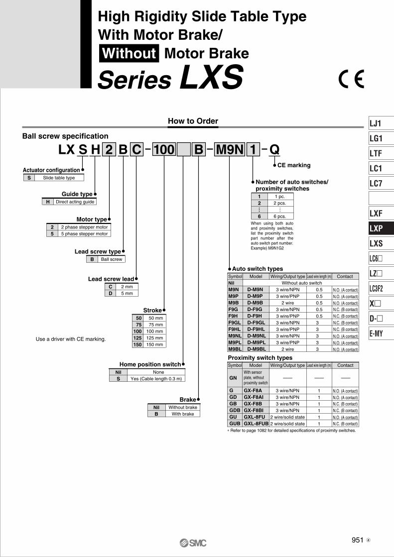
2 mm5 mm
CD
Lead screw lead
2 phase stepper motor5 phase stepper motor
25
Motor type
Ball screwB
Lead screw type
50 mm75 mm
100 mm125 mm150 mm
5075
100125150
Stroke
Use a driver with CE marking.
1 pc.2 pcs.
6 pcs.
12
6
Number of auto switches/proximity switches
Home position switch
… …
When using both auto and proximity switches, list the proximity switch part number after the auto switch part number.Example) M9N1G2
NoneYes (Cable length 0.3 m)
NilS
Brake
Auto switch typesSymbolNilM9NM9PM9BF9GF9HF9GLF9HLM9NLM9PLM9BL
D-M9ND-M9PD-M9BD-F9GD-F9HD-F9GLD-F9HLD-M9NLD-M9PLD-M9BL
Model Wiring/Output type
3 wire/NPN3 wire/PNP
2 wire3 wire/NPN3 wire/PNP3 wire/NPN3 wire/PNP3 wire/NPN3 wire/PNP
2 wire
Lead wire length (m)
0.50.50.50.50.53 3 3 3 3
Contact
N.O. (A contact)N.O. (A contact)N.O. (A contact)N.C. (B contact)N.C. (B contact)N.C. (B contact)N.C. (B contact)
N.O. (A contact)N.O. (A contact)N.O. (A contact)
Without auto switch
Ball screw specification
LX S H 2 B 1C 100 M9NB
Slide table typeS
Actuator configuration
Direct acting guideH
Guide type
Without brakeWith brake
NilB
CE marking
Q
Proximity switch typesSymbol
GGDGBGDBGUGUB
GN
GX-F8AGX-F8AIGX-F8BGX-F8BIGXL-8FUGXL-8FUB
Model Wiring/Output type
3 wire/NPN3 wire/NPN3 wire/NPN3 wire/NPN
2 wire/solid state2 wire/solid state
Lead wire length (m)
111111
Contact
——————
N.O. (A contact)N.O. (A contact)N.C. (B contact)N.C. (B contact)
N.O. (A contact)N.C. (B contact)
∗ Refer to page 1082 for detailed specifications of proximity switches.
With sensor plate, without proximity switch
How to Order
951
High Rigidity Slide Table TypeWith Motor Brake/ Without Motor Brake
Series LXS LJ1
LG1
LTF
LC1
LC7
LXF
LXP
LXS
LC6�
LZ�
LC3F2
X�
D-�
E-MY
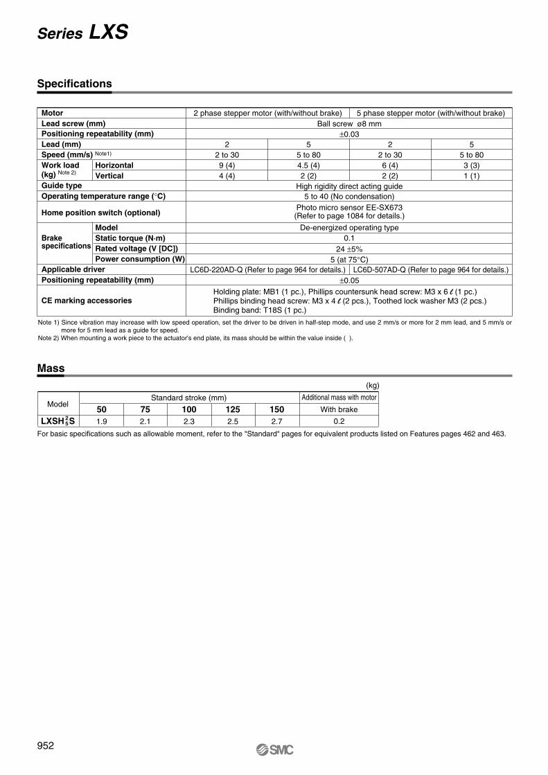
Specifications
Ball screw ø8 mm±0.03
22 to 309 (4)4 (4)
55 to 804.5 (4)2 (2)
22 to 306 (4)2 (2)
55 to 803 (3)1 (1)
LC6D-220AD-Q (Refer to page 964 for details.) LC6D-507AD-Q (Refer to page 964 for details.)
High rigidity direct acting guide5 to 40 (No condensation)
De-energized operating type0.1
24 ±5%5 (at 75°C)
±0.05
2 phase stepper motor (with/without brake) 5 phase stepper motor (with/without brake)
HorizontalVertical
ModelStatic torque (N·m)Rated voltage (V [DC])Power consumption (W)
Photo micro sensor EE-SX673 (Refer to page 1084 for details.)
Holding plate: MB1 (1 pc.), Phillips countersunk head screw: M3 x 6 l (1 pc.)Phillips binding head screw: M3 x 4 l (2 pcs.), Toothed lock washer M3 (2 pcs.)Binding band: T18S (1 pc.)
Note 1) Since vibration may increase with low speed operation, set the driver to be driven in half-step mode, and use 2 mm/s or more for 2 mm lead, and 5 mm/s or more for 5 mm lead as a guide for speed.Note 2) When mounting a work piece to the actuator's end plate, its mass should be within the value inside ( ).
Mass
LXSH S
ModelAdditional mass with motor
With brake
0.2
Standard stroke (mm)
(kg)
501.9
752.1
1002.3
1252.5
1502.72
5
MotorLead screw (mm)Positioning repeatability (mm)Lead (mm)Speed (mm/s) Note1)
Work load (kg) Note 2)
Guide typeOperating temperature range (°C)
Home position switch (optional)
Brake specifications
Applicable driverPositioning repeatability (mm)
CE marking accessories
For basic specifications such as allowable moment, refer to the "Standard" pages for equivalent products listed on Features pages 462 and 463.
952
Series LXS
P0950-P0953-E.qxd 10.12.15 11:51 AM Page 952
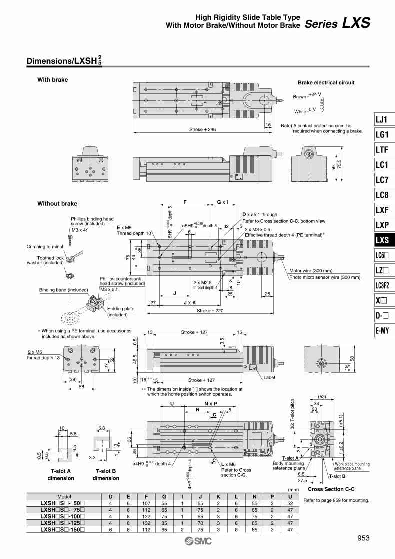
ModelLXSH�S�- 50�LXSH�S�- 75�LXSH�S�-100�LXSH�S�-125�LXSH�S�-150�
D44446
E66888
F107112122132112
G5565758565
I11112
J6575657075
K22333
L66668
N5565758565
P22223
U5247474747
(mm)
Brake electrical circuit
Note) A contact protection circuit is required when connecting a brake.
+24 V
0 V
59
16
75.5
With brake
Stroke + 246
Brown
White
LXSH ∗ S ∗ — ∗∗∗∗B — ∗∗∗∗ — Q
C
C
L x M6Refer to Cross section C-C.
T-slot Adimension
T-slot Bdimension
T-slot Aø4H9+0.030
0 depth 4 Body mountingreference plane
6.5
6.5
3.3
5.8
13
1 ±0
.2(ø
5.1)
36: T
-slo
t pitc
h
20
28
5
4H9+ 0
.030
0de
pth
4
15(5)
0.5
46.5
13 15
3.5
2 x M6
E x M5
thread depth 4
27 19
6
38
58
52 58
76 46
Stroke + 220
25258
10
32 x M2.5
36
U(52)
28
T-slot B
Work piece mountingreference plane
27.5
Cross Section C-C
10.5
4 5.510
6.5
39
(39)
thread depth 13
Motor wire (300 mm)Photo micro sensor wire (300 mm)
Without brake
D x ø5.1 throughRefer to Cross section C-C, bottom view.
ø5H9+0.030 0 depth 5
5H9
+ 0.0
30
0de
pth
5
J
Thread depth 10
27 J x K
N
Stroke + 127
Stroke + 127
N x P
F G x I
[18]∗∗
2 x M3 x 0.5Effective thread depth 4 (PE terminal)∗
Label
LXSH ∗ S ∗ — ∗∗∗∗B — ∗∗∗∗ — Q
32 5
Phillips countersunk head screw (included)
Binding band (included)
Toothed lockwasher (included)
Crimping terminal
M3 x 6 l
M3 x 4l
Holding plate(included)
Phillips binding head screw (included)
∗ When using a PE terminal, use accessories included as shown above.
Refer to page 959 for mounting.
Dimensions/LXSH 25
∗∗ The dimension inside [ ] shows the location at which the home position switch operates.
953
Series LXSHigh Rigidity Slide Table TypeWith Motor Brake/Without Motor Brake
LJ1
LG1
LTF
LC1
LC7
LC8
LXF
LXP
LXS
LC6�
LZ�
LC3F2
X�
D-�
E-MY
P0950-P0953-E.qxd 10.12.15 11:51 AM Page 953

Construction
Series LXF
No.
10
11
12
13
14
15
16
Description Material Note
Parts list
Stopper B
Sensor plate
Coupling
Magnet
Bumper
Motor cover
Photo micro sensor
Aluminum alloy
Mild steel
Aluminum alloy
—
Rubber
Resin
—
Chromated
w y
qer
t
i
o
!4
!0 !1 !6
!5!2!3
u
No.
1
2
3
4
5
6
7
8
9
Description Material Note
Parts list
Motor
Direct acting guide
Nut
Rolled screw
Body
Table
End plate
Tube
Stopper A
—
—
Resin/Alloy steel
Alloy steel
Aluminum alloy
Aluminum alloy
Aluminum alloy
Aluminum alloy
—
Anodized
Anodized
Anodized
Anodized
954
Series LXConstruction
P0954-P0956-E.qxd 10.12.15 11:52 AM Page 954

Series LXP
No.
12
13
14
15
16
17
18
19
20
21
22
23
Description Material Note
Parts list
Photo micro sensor
Lock nut
Stopper nut
Bumper bolt
Bumper
Motor cover
Tension ring
Cable cap
Plug
Magnet
Adaptor
Plate mounting bolt
—
Carbon steel
Aluminum alloy
Bearing steel
Resin
Resin
Stainless steel
—
Aluminum alloy
Carbon steel
Black zinc chromated
Nickel plated
Nickel plated
No.
1
2
3
4
5
6
7
8
9
10
11
Description Material Note
Parts list
Motor
Rolled screw
Nut
Coupling
Bearing
Body
Mounting plate
Ball bushing
Guide rod
Tube
Sensor pin
—
Alloy steel
Resin
—
—
Aluminum alloy
Mild steel
—
Bearing steel
Aluminum alloy
Stainless steel
Stepper motor
Anodized
Nickel plated
Chrome plated
Anodized
w e
q
t r
yu
i o
@3
@0
@2
@1!6 !5 !0 !8 !3
!7!9!2!1!4
955
Construction
Series LXShort StrokeElectric Actuator
LJ1
LG1
LTF
LC1
LC7
LC8
LXF
LXP
LXS
LC6�
LZ�
LC3F2
X�
D-�
E-MY
P0954-P0956-E.qxd 10.12.15 11:52 AM Page 955
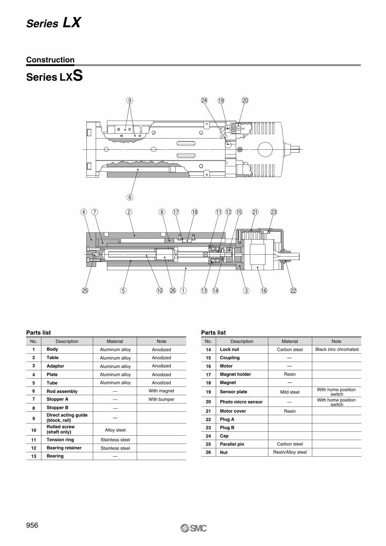
Series LXS
q
wu
et
r
y
i
o @4 @0
@1 @3
@5 @6 @2!6
!7 !8 !1 !2 !5
!0
!9
!3 !4
No.
14
15
16
17
18
19
20
21
22
23
24
25
26
Description Material Note
Parts list
Lock nut
Coupling
Motor
Magnet holder
Magnet
Sensor plate
Photo micro sensor
Motor cover
Plug A
Plug B
Cap
Parallel pin
Nut
Carbon steel
Resin
—
Mild steel
Resin
Carbon steel
Resin/Alloy steel
Black zinc chromated
With home position switch
With home position switch
No.
1
2
3
4
5
6
7
8
9
10
11
12
13
Description Material Note
Parts list
Body
Table
Adaptor
Plate
Tube
Rod assembly
Stopper A
Stopper B
Direct acting guide (block, rail)Rolled screw (shaft only)
Tension ring
Bearing retainer
Bearing
Aluminum alloy
Aluminum alloy
Aluminum alloy
Aluminum alloy
Aluminum alloy
—
Alloy steel
Stainless steel
Stainless steel
Anodized
Anodized
Anodized
Anodized
Anodized
With magnet
With bumper
—
—
—
—
—
—
—
956
Series LX
Construction
P0954-P0956-E.qxd 10.12.15 11:52 AM Page 956
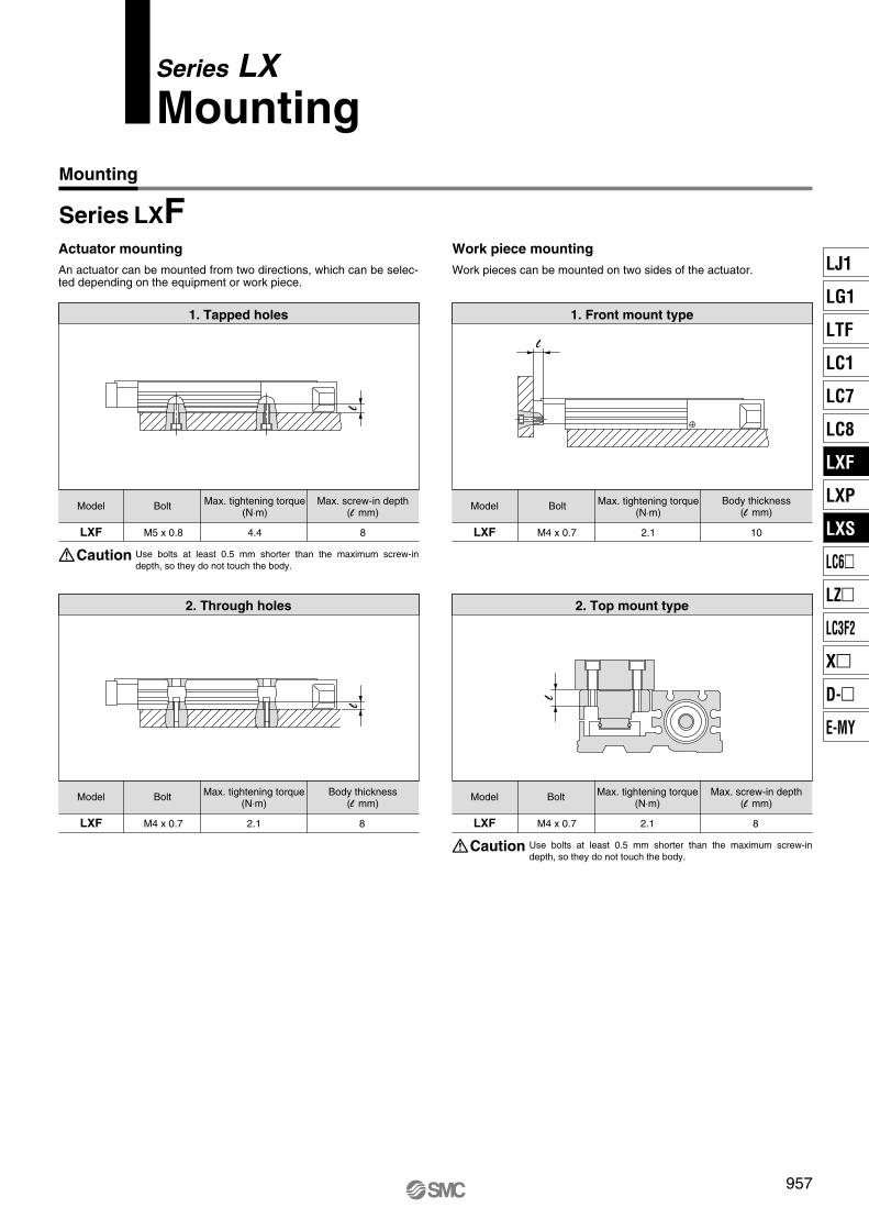
Series LXMounting
Actuator mounting Work piece mountingWork pieces can be mounted on two sides of the actuator.
1. Tapped holes
Model Bolt Max. tightening torque(N⋅m)
Max. screw-in depth(l mm)
LXF M5 x 0.8 4.4 8
2. Through holes
Model Bolt Max. tightening torque(N⋅m)
LXF M4 x 0.7 2.1 8
Body thickness(l mm)
Use bolts at least 0.5 mm shorter than the maximum screw-in depth, so they do not touch the body.
Caution
1. Front mount type
Model Bolt Max. tightening torque(N⋅m)
Body thickness(l mm)
LXF M4 x 0.7 2.1 10
2. Top mount type
Model Bolt Max. tightening torque(N⋅m)
LXF M4 x 0.7 2.1 8
Max. screw-in depth(l mm)
Use bolts at least 0.5 mm shorter than the maximum screw-in depth, so they do not touch the body.
Caution
l
l
ll
An actuator can be mounted from two directions, which can be selec-ted depending on the equipment or work piece.
957
Mounting
Series LXFLJ1
LG1
LTF
LC1
LC7
LC8
LXF
LXP
LXS
LC6�
LZ�
LC3F2
X�
D-�
E-MY
P0957-E.qxd 10.12.15 11:52 AM Page 957
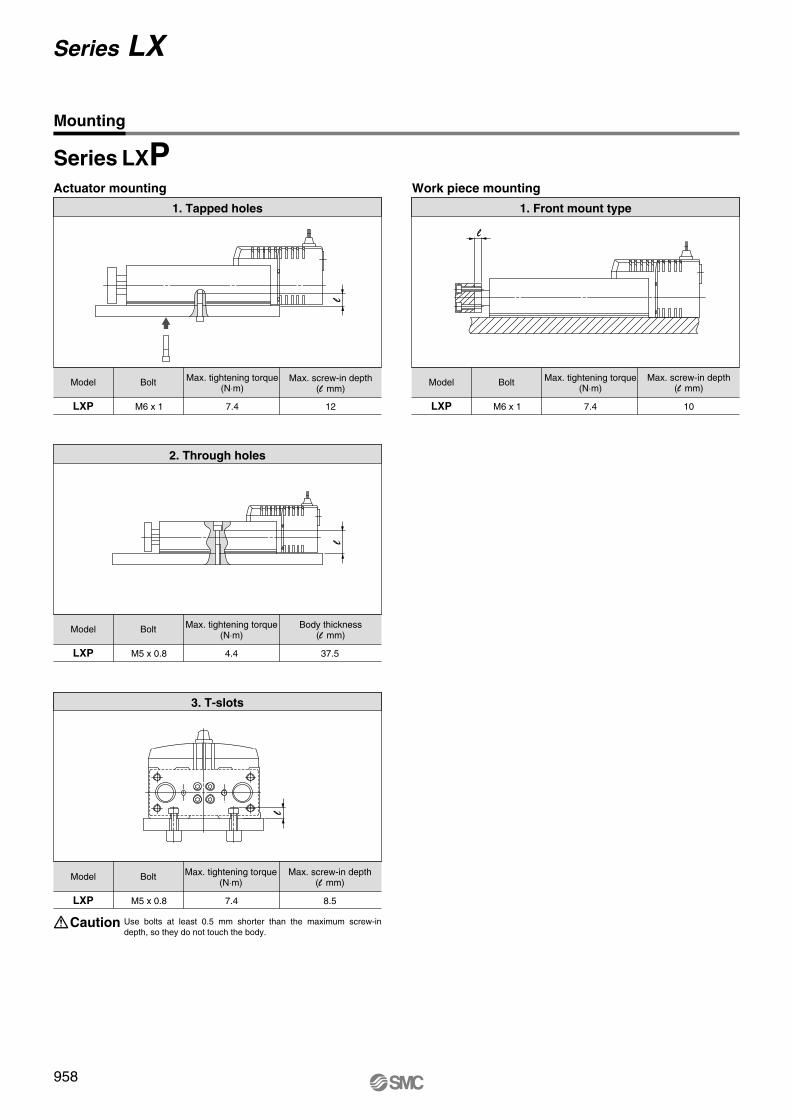
Actuator mounting Work piece mounting
1. Tapped holes
Model Bolt Max. tightening torque(N⋅m)
LXP M6 x 1 7.4 12
Model Bolt Max. tightening torque(N⋅m)
LXP M5 x 0.8 4.4 37.5
Body thickness(l mm)
Use bolts at least 0.5 mm shorter than the maximum screw-in depth, so they do not touch the body.
Caution
1. Front mount type
Model Bolt Max. tightening torque(N⋅m)
Max. screw-in depth(l mm)
LXP M6 x 1 7.4 10
Max. screw-in depth(l mm)
3. T-slots
Model Bolt Max. tightening torque(N⋅m)
LXP M5 x 0.8 7.4 8.5
Max. screw-in depth(l mm)
l
l
ll
2. Through holes
Mounting
958
Series LX
Series LXP
P0958-P0962-E.qxd 10.12.15 11:52 AM Page 958
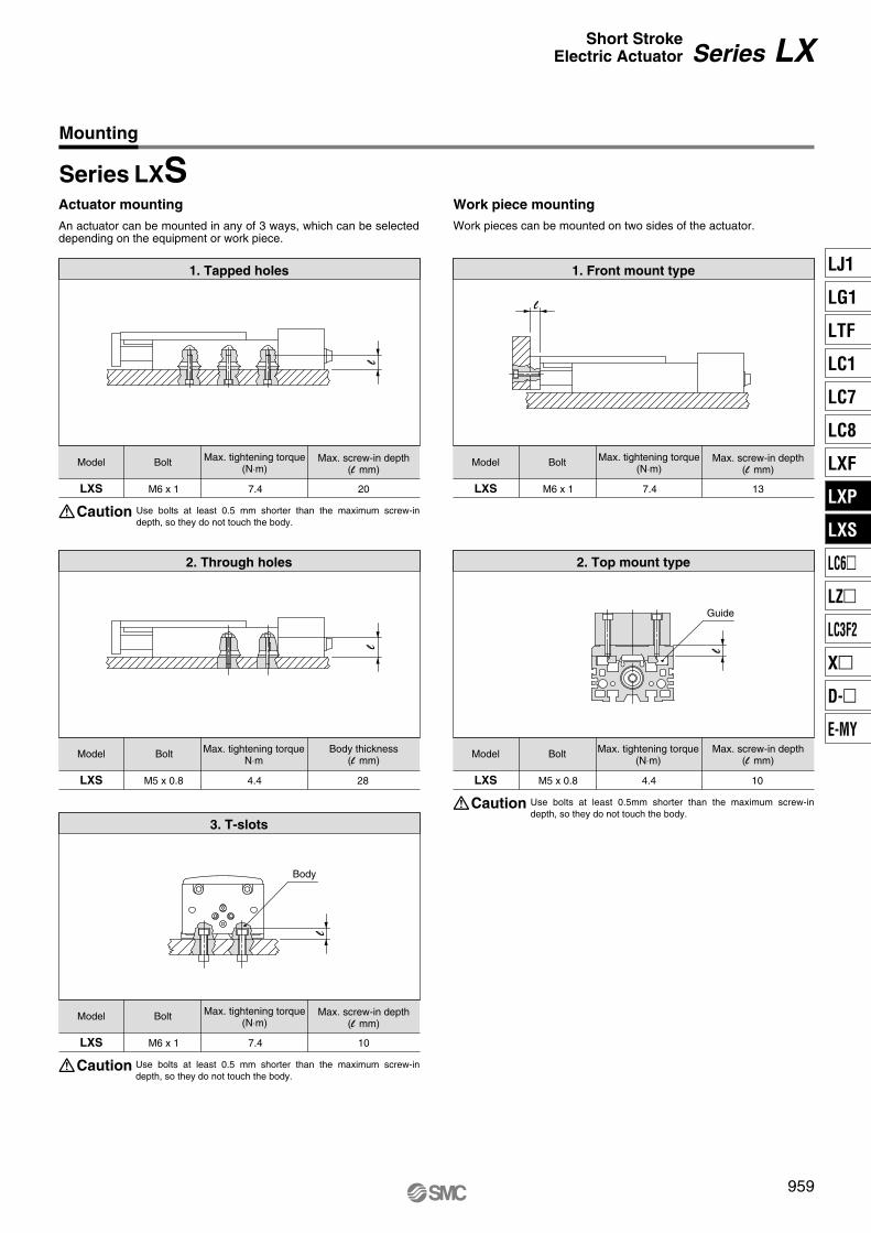
Actuator mounting Work piece mountingWork pieces can be mounted on two sides of the actuator.
1. Tapped holes
Model Bolt Max. tightening torque(N⋅m)
Body thickness(l mm)
LXS M6 x 1 7.4 20
2. Through holes
Model Bolt Max. tightening torqueN⋅m
LXS M5 x 0.8 4.4 28
Max. screw-in depth(l mm)
Use bolts at least 0.5 mm shorter than the maximum screw-in depth, so they do not touch the body.
Caution
1. Front mount type
Model Bolt Max. tightening torque(N⋅m)
LXS M6 x 1 7.4 13
2. Top mount type
Model Bolt Max. tightening torque(N⋅m)
LXS M5 x 0.8 4.4 10
Max. screw-in depth(l mm)
Use bolts at least 0.5mm shorter than the maximum screw-in depth, so they do not touch the body.
Caution3. T-slots
Model Bolt Max. tightening torque(N⋅m)
LXS M6 x 1 7.4 10
Max. screw-in depth(l mm)
Use bolts at least 0.5 mm shorter than the maximum screw-in depth, so they do not touch the body.
Caution
Max. screw-in depth(l mm)
Body
Guide
l
l
ll
l
An actuator can be mounted in any of 3 ways, which can be selected depending on the equipment or work piece.
959
Mounting
Series LXS
Series LXShort StrokeElectric Actuator
LJ1
LG1
LTF
LC1
LC7
LC8
LXF
LXP
LXS
LC6�
LZ�
LC3F2
X�
D-�
E-MY
P0958-P0962-E.qxd 10.12.15 11:52 AM Page 959
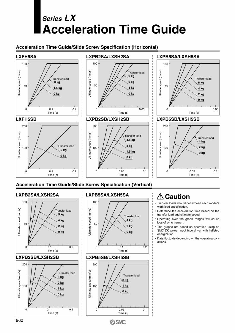
Series LXAcceleration Time Guide
LXFH5SA
LXFH5SB
LXPB2SA/LXSH2SA
LXPB2SB/LXSH2SB
LXPB2SB/LXSH2SB LXPB5SB/LXSH5SB
LXPB5SA/LXSH5SA
LXPB5SB/LXSH5SB
LXPB5SA/LXSH5SA
• Transfer loads should not exceed each model's work load specification.
• Determine the acceleration time based on the transfer load and ultimate speed.
• Operating over the graph ranges will cause loss of synchronism.
• The graphs are based on operation using an SMC DC power input type driver with halfstep energization.
• Data fluctuate depending on the operating con-ditions.
100
50
0 0.1 0.2
Ulti
mat
e sp
eed
(mm
/s)
Time (s)
3 kg
1.5 kg
0 kg
100
50
0 0.05
Ulti
mat
e sp
eed
(mm
/s)
Time (s)
Transfer load9 kg
6 kg
3 kg
200
100
0 0.1 0.2
Ulti
mat
e sp
eed
(mm
/s)
Time (s)
Transfer load
2 kg
0 kg
200
100
0 0.05 0.1
Ulti
mat
e sp
eed
(mm
/s)
Time (s)
Transfer load
4.5 kg
3 kg
1.5 kg
200
100
0 0.1 0.2
Ulti
mat
e sp
eed
(mm
/s)
Time (s)
Transfer load3 kg
2 kg
1 kg
200
100
0 0.1
Ulti
mat
e sp
eed
(mm
/s)
Time (s)
Transfer load
2 kg
1 kg
0 kg
100
50
0 0.05
Ulti
mat
e sp
eed
(mm
/s)
Time (s)
Transfer load6 kg
4 kg
2 kg
200
100
0 0.05 0.1
Ulti
mat
e sp
eed
(mm
/s)
Time (s)
Transfer load4 kg
2 kg
0 kg
100
50
0 0.1 0.2
Ulti
mat
e sp
eed
(mm
/s)
Time (s)
Transfer load
4 kg
2 kg
0 kg
Transfer load
0 kg
0 kg
0 kg
LXPB2SA/LXSH2SA100
50
0 0.2
Ulti
mat
e sp
eed
(mm
/s)
Time (s)
Transfer load5 kg
4 kg
2 kg
0 kg
0 kg
0.05
Caution
0.1
960
Acceleration Time Guide/Slide Screw Specification (Horizontal)
Acceleration Time Guide/Slide Screw Specification (Vertical)
P0958-P0962-E.qxd 10.12.15 11:52 AM Page 960
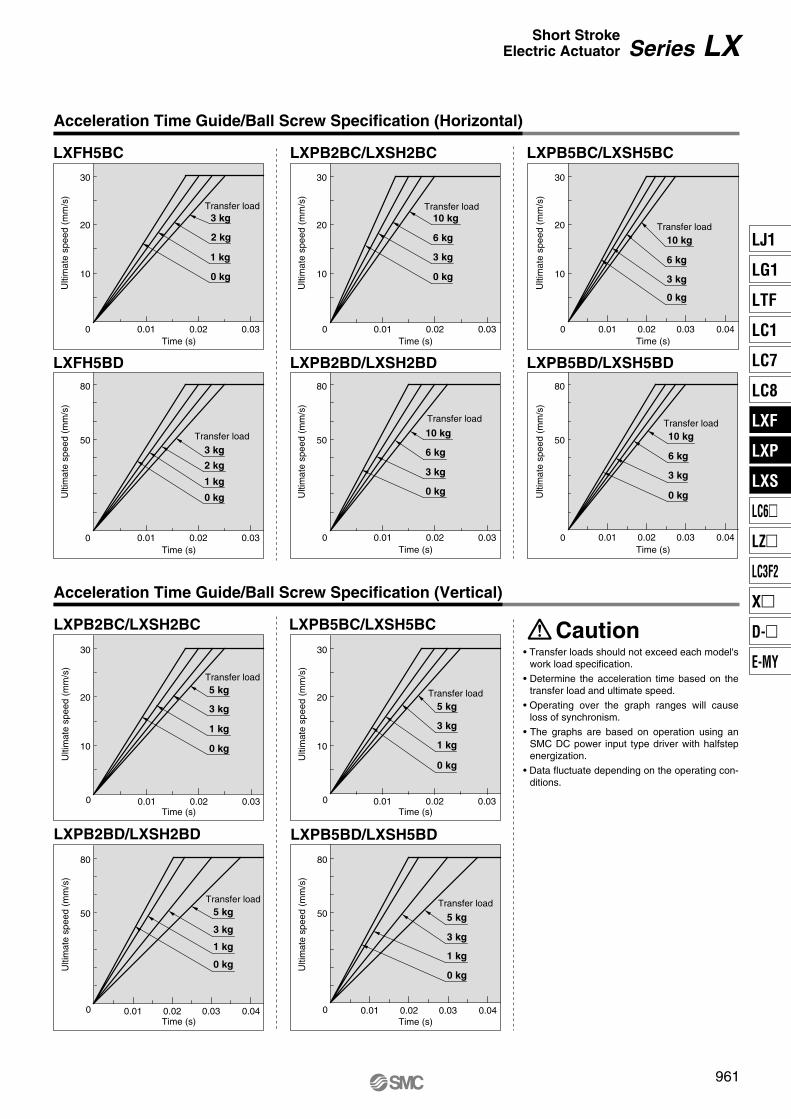
LXFH5BC
LXFH5BD
LXPB2BC/LXSH2BC
LXPB2BD/LXSH2BD
LXPB2BD/LXSH2BD LXPB5BD/LXSH5BD
LXPB5BC/LXSH5BC
LXPB5BD/LXSH5BD
LXPB5BC/LXSH5BC
• Transfer loads should not exceed each model's work load specification.
• Determine the acceleration time based on the transfer load and ultimate speed.
• Operating over the graph ranges will cause loss of synchronism.
• The graphs are based on operation using an SMC DC power input type driver with halfstep energization.
• Data fluctuate depending on the operating con-ditions.
30
10
20
30
10
20
30
10
20
0 0.01 0.02 0.03
0.01 0.02 0.03
0.01 0.02 0.03 0.01 0.02 0.03
30
10
20
30
10
20
0.01 0.02 0.03
0.01 0.02 0.03
Ulti
mat
e sp
eed
(mm
/s)
Time (s)0
Ulti
mat
e sp
eed
(mm
/s)
Time (s)
Transfer load10 kg
6 kg
3 kg
0 kg
80
50
80
50
80
50
80
50
80
50
0
Ulti
mat
e sp
eed
(mm
/s)
Time (s)
Transfer load
3 kg
1 kg
0 kg
2 kg
0
Ulti
mat
e sp
eed
(mm
/s)
Time (s)
Transfer load
10 kg
6 kg
3 kg
0 kg
0
Ulti
mat
e sp
eed
(mm
/s)
Time (s)
Transfer load5 kg
3 kg
0
Ulti
mat
e sp
eed
(mm
/s)
Time (s)
Transfer load
5 kg
3 kg
1 kg
0 kg
0 0.01 0.02 0.03 0.04
0.01 0.02 0.03 0.04
0.01 0.02 0.03 0.04 0.01 0.02 0.03 0.04
Ulti
mat
e sp
eed
(mm
/s)
Time (s)
Transfer load
10 kg
6 kg
3 kg
0 kg
0U
ltim
ate
spee
d (m
m/s
)Time (s)
Transfer load10 kg
6 kg
3 kg
0 kg
0
Ulti
mat
e sp
eed
(mm
/s)
Time (s)
Transfer load5 kg
3 kg
1 kg
0 kg
LXPB2BC/LXSH2BC
0
Ulti
mat
e sp
eed
(mm
/s)
Time (s)
Transfer load5 kg
3 kg
1 kg
0 kg
Caution
Transfer load3 kg
2 kg
1 kg
0 kg
1 kg
0 kg
961
Acceleration Time Guide/Ball Screw Specification (Horizontal)
Acceleration Time Guide/Ball Screw Specification (Vertical)
Series LXShort StrokeElectric Actuator
LJ1
LG1
LTF
LC1
LC7
LC8
LXF
LXP
LXS
LC6�
LZ�
LC3F2
X�
D-�
E-MY
P0958-P0962-E.qxd 10.12.15 11:52 AM Page 961
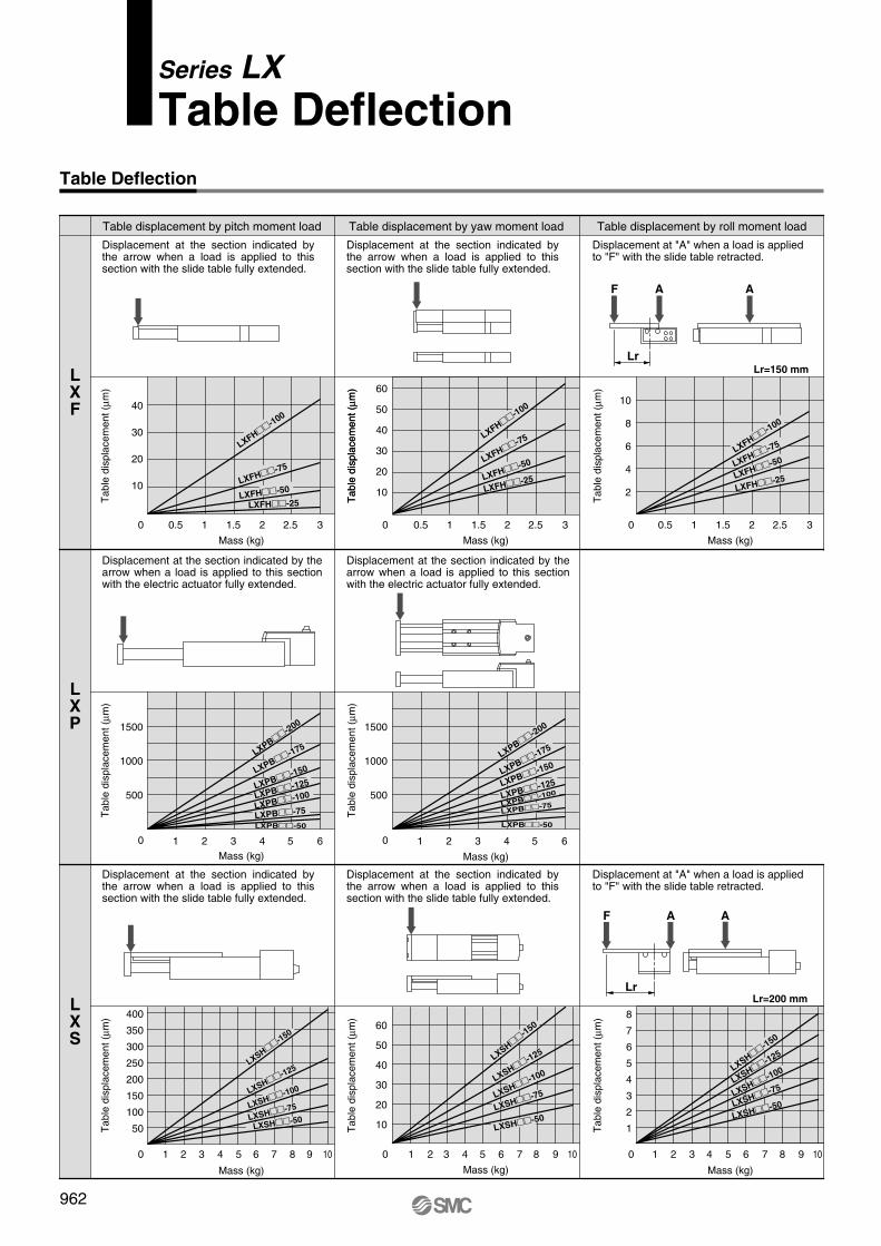
Series LXTable Deflection
Lr
F A A
Lr
F A A
Table displacement by pitch moment load
0
Mass (kg)
Mass (kg)
Mass (kg)
Tab
le d
ispl
acem
ent (
µm)
Tab
le d
ispl
acem
ent (
µm)
Tab
le d
ispl
acem
ent (
µm)
Tab
le d
ispl
acem
ent (
µm)
Tab
le d
ispl
acem
ent (
µm)
Tab
le d
ispl
acem
ent (
µm)
Tab
le d
ispl
acem
ent (
µm)
Tab
le d
ispl
acem
ent (
µm)
Tab
le d
ispl
acem
ent (
µm)
Table displacement by yaw moment load
0
Table displacement by roll moment load
0
Mass (kg)
Mass (kg)
0 0
0 0
Mass (kg)
Mass (kg)
Mass (kg)
0
LXF
LXP
LXS
40
30
20
10
60
50
40
30
20
10
0.5 1 1.5 2 2.5 3 0.5 1 1.5 2 2.5 3
10
8
6
4
2
0.5 1 1.5 2 2.5 3
1500
1000
500
1 2 3 4 5 6
1500
1000
500
1 2 3 4 5 6
400
350
300
250
200
150
100
50
1 2 3 4 5 6 8 9 10 10 107 1 2 3 4 5 6 8 97
60
50
40
30
20
10
1 2 3 4 5 6 8 97
8
7
6
5
4
3
2
1
LXFH��-100
LXFH��-75
LXFH��-50
LXFH��-25
LXFH��-100
LXFH��-75
LXFH��-50
LXFH��-25
LXFH��-100
LXFH��-75
LXFH��-50
LXFH��-25
LXPB��-200
LXPB��-175
LXPB��-150
LXPB��-125
LXPB��-100
LXPB��-75
LXPB��-50
LXPB��-200
LXPB��-175
LXPB��-150
LXPB��-125
LXPB��-100
LXPB��-75
LXPB��-50
LXSH��-150
LXSH��-125
LXSH��-100
LXSH��-75
LXSH��-50
LXSH��-150
LXSH��-125
LXSH��-100
LXSH��-75
LXSH��-50
LXSH��-150
LXSH��-125
LXSH��-100
LXSH��-75
LXSH��-50
Lr=150 mm
Lr=200 mm
Displacement at the section indicated by the arrow when a load is applied to this section with the slide table fully extended.
Displacement at the section indicated by the arrow when a load is applied to this section with the slide table fully extended.
Displacement at "A" when a load is applied to "F" with the slide table retracted.
Displacement at the section indicated by the arrow when a load is applied to this section with the electric actuator fully extended.
Displacement at the section indicated by the arrow when a load is applied to this section with the electric actuator fully extended.
Displacement at the section indicated by the arrow when a load is applied to this section with the slide table fully extended.
Displacement at the section indicated by the arrow when a load is applied to this section with the slide table fully extended.
Displacement at "A" when a load is applied to "F" with the slide table retracted.
962
Table Deflection
P0958-P0962-E.qxd 10.12.15 11:52 AM Page 962
![VALVULA DE BOLA BRIDA DA CON ACTUADOR NEUMATICOArt. 720000], acciaio inox AISI 304, con attuatore elettrico.], stainless steel AISI 304, with electric actuator. Art. 722000], acciaio](https://img.pdfslide.tips/doc/110x75/61291316e08dc879e620625d/valvula-de-bola-brida-da-con-actuador-art-720000-acciaio-inox-aisi-304-con-attuatore.jpg)


![Manipulation System · Electric 3-axis manipulator Electric 2-axis sample stage Electric injector Piezoelectric actuator Stroke / Capacity 20 [mm] 1,178 [μl] 5 [μm] Resolution [μm]](https://img.pdfslide.tips/doc/110x75/60652d7822a20173f93eeb8c/manipulation-electric-3-axis-manipulator-electric-2-axis-sample-stage-electric-injector.jpg)