Embed Size (px)
Citation preview

Sicma S.p.A. Miglianico (CH)
page 1

Sicma S.p.A. Miglianico (CH)
page 2

Sicma S.p.A. Miglianico (CH)
page 3
c.da Cerreto - 66010 Miglianico (CH) Telephone +39 (0)871 95841 Fax +39 (0)871 950295 - Telex 600865 SICMA I
web: www.sicma.it - e-mail: [email protected]
© SICMA s.p.a. All rights reserved Printed in Italy
Industrial Manufacture Company of Agricultural Machines No part of this manual shall be reproduced, copied or disseminated by any means without SICMA joint-stock company prior authorization in writing. SICMA joint-stock company reserves the right to make any necessary changes without giving prior notice in order to optimize the quality and safety of its products and without committing itself to update this manual every time a change takes place. This booklet provides an accurate description of the operating instructions and maintenance activities to be carried out on the tiller you bought. We congratulate you on your choice and remind you that reading and following scrupulously all prescriptions here contained will assure the regular working of your machine and especially a high degree of safety. The manufacturer therefore declines all responsibility as for the onset of problems caused by a lack of compliance with the instructions and/or negligence of the operator. This manual is divided into chapters and paragraphs and its pages are progressively numbered in order to present information in a clear and concise way. Information, thus, can be found through the keywords used as chapters’ title and especially consulting the index (page 4).

Sicma S.p.A. Miglianico (CH)
page 4
INDEX General information
Symbols Page 5
Tightening table Page 5
Safety labels Page 6
Technical data Page 7/8
Main parts Page 9
Identification plates Page 9
Allowed/improper use Page 9
Safety
Safety in the workplace Page 9
Job clothing Page 10
General safety rules Page 10/11
Set up
Connection to the tractor Page 12
Connection through Cardan joint Page 13
Cover adjustment Page 13
Working depth Page 13/14
Speed gear Page 14/15
Chain tension Page 15
Side shift regulation Page 15
SH side shift Page 16/17
Starting up Page 17
Road transport Page 17
Set aside Page 17
Maintenance
Maintenance program Page 19/20
Blade replacement Page 20
Spare parts Page 21

Sicma S.p.A. Miglianico (CH)
page 5
GENERAL INFORMATION SYMBOLS This booklet contains three “safety graphic symbols” to highlight as many danger levels or important information:
It draws the operator’s attention to situations which can jeopardize people’s safety.
It draws the attention to situations which jeopardize the machine efficiency but not people’s safety.
It highlights general information which does not endanger people’s safety or the efficiency of the parts.
BOLTS AND NUTS TIGHTENING TABLE In order to tighten correctly all bolts and nuts of your tiller, we advice you to use a special dynamometrical spanner and to refer to the following table:
Screws/threaded bolts
Bolt class
8.8 10.9
thread
Nm Lb-ft Nm Lb-ft M6 11 8.5 17 12 M8 28 20 40 30 M10 55 40 80 60 M12 95 70 140 105 M14 150 110 225 165 M16 240 175 305 225 M18 330 250 475 350

Sicma S.p.A. Miglianico (CH)
page 6
SAFETY LABELS The safety labels and the information on the machine, listed in the following table, must be necessarily carried out; failure to carry out these warnings can cause death or severe injuries. Make sure that the labels are always present and legible, should this not be the case contact your nearest SICMA dealer to replace the missing or illegible ones.
4
Use a 540 rpm power takeoff.
1
Attention: read carefully all instruction and safety rules before using the machine. Stop engine and remove key before starting maintenance or repairs.
7
Hooking point for the machine’s lifting.
2
Danger of feet injuries: rotating tools, keep away from the machine.
5
Danger of feet injuries: keep a safety distance from the machine.
3
Thrown objects: keep a safety distance from the machine. Danger of hands injuries: do not open or remove safety guards while the machine is operating.
6
Danger of hands injuries: keep safety guards in position while operating.

Sicma S.p.A. Miglianico (CH)
page 7
Technical data
Working depth Driveline
Blades (No) Blade type
Model Working
width (cm)
Horse-power (CV)
weight (Kg)
cm inc
Speed gear
chain gear 4 6 curved “L”
shaped
85 85 10-10 106 15 6 x x x
105 105 10-10 118 15 6 x x x SA
125 125 10-10 130 15 6 x x x
90 90 20-35 126 18 7 x x x x
100 100 20-35 130 18 7 x x x x
110 110 20-35 136 18 7 x x x x
120 120 20-35 152 18 7 x x x x
130 130 20-35 158 18 7 x x x x
140 140 20-35 166 18 7 x x x x
ZL-L
150 150 20-35 190 18 7 x x x x
110 110 20-35 165 18 7 x x x x
120 120 20-35 170 18 7 x x x x
130 130 20-35 175 18 7 x x x x SB
140 140 20-35 180 18 7 x x x x x
105 105 30-50 220 18 7 x x x x x x
125 125 30-50 230 18 7 x x x x x x
135 135 30-50 238 18 7 x x x x x x
145 145 30-50 246 18 7 x x x x x x
165 165 30-50 266 18 7 x x x x x x
CS
185 185 30-50 290 18 7 x x x x x x
125 125 20-50 200 18 7 x x x x x
145 145 20-50 284 18 7 x x x x x
165 165 20-50 294 18 7 x x x x x SF
185 185 20-50 350 18 7 x x x x x
120 120 30-60 312 20 8 x x x x x x
130 130 30-60 340 20 8 x x x x x x
145 145 30-60 358 20 8 x x x x x x
155 155 30-60 380 20 8 x x x x x x
180 180 30-60 394 20 8 x x x x x x
ST
205 205 30-60 400 20 8 x x x x x x
130 130 30-60 290 22 8 x x x x x
140 140 30-60 300 22 8 x x x x x
155 155 30-60 320 22 8 x x x x x SD
180 180 30-60 360 22 8 x x x x x
135 135 35-60 420 22 8 x x x x x
150 150 35-60 445 22 8 x x x x x
160 160 35-60 458 22 8 x x x x x
185 185 35-60 500 22 8 x x x x x
SHV SHF SHE
210 210 35-60 534 22 8 x x x x x
Sicma S.p.A. Miglianico (CH)
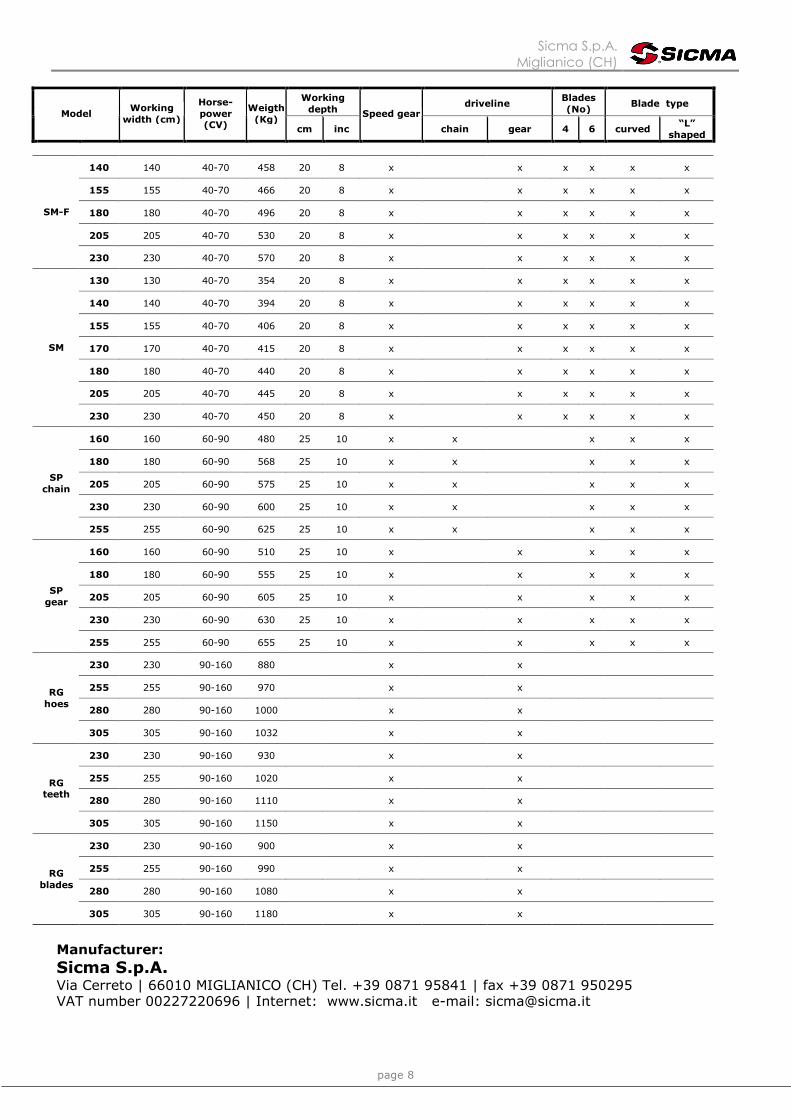
page 8
Working depth
driveline Blades (No)
Blade type Model
Working width (cm)
Horse-power (CV)
Weigth (Kg)
cm inc
Speed gear
chain gear 4 6 curved “L”
shaped
140 140 40-70 458 20 8 x x x x x x
155 155 40-70 466 20 8 x x x x x x
180 180 40-70 496 20 8 x x x x x x
205 205 40-70 530 20 8 x x x x x x
SM-F
230 230 40-70 570 20 8 x x x x x x
130 130 40-70 354 20 8 x x x x x x
140 140 40-70 394 20 8 x x x x x x
155 155 40-70 406 20 8 x x x x x x
170 170 40-70 415 20 8 x x x x x x
180 180 40-70 440 20 8 x x x x x x
205 205 40-70 445 20 8 x x x x x x
SM
230 230 40-70 450 20 8 x x x x x x
160 160 60-90 480 25 10 x x x x x
180 180 60-90 568 25 10 x x x x x
205 205 60-90 575 25 10 x x x x x
230 230 60-90 600 25 10 x x x x x
SP chain
255 255 60-90 625 25 10 x x x x x
160 160 60-90 510 25 10 x x x x x
180 180 60-90 555 25 10 x x x x x
205 205 60-90 605 25 10 x x x x x
230 230 60-90 630 25 10 x x x x x
SP gear
255 255 60-90 655 25 10 x x x x x
230 230 90-160 880 x x
255 255 90-160 970 x x
280 280 90-160 1000 x x
RG hoes
305 305 90-160 1032 x x
230 230 90-160 930 x x
255 255 90-160 1020 x x
280 280 90-160 1110 x x
RG teeth
305 305 90-160 1150 x x
230 230 90-160 900 x x
255 255 90-160 990 x x
280 280 90-160 1080 x x
RG blades
305 305 90-160 1180 x x
Manufacturer: Sicma S.p.A. Via Cerreto | 66010 MIGLIANICO (CH) Tel. +39 0871 95841 | fax +39 0871 950295 VAT number 00227220696 | Internet: www.sicma.it e-mail: [email protected]

Sicma S.p.A. Miglianico (CH)
page 9
MAIN PARTS TERMINOLOGY
A) Frame B) Lower three-point hitches C) Upper three-point hitch D) Cardan guard E) Third point mast F) Rotor G) Hoes H) Side skids I) Transmission case L) Cover
IDENTIFICATION PLATES Identification plates are placed on every tiller and are structured as follows:
model of tiller (example) dimension (example) Speed gear information (example)
When asking for information or technical service, always specify the machine type and width.
ALLOWED USE SICMA tillers, as described in this instruction and maintenance booklet, have been specifically designed to till the land. Any other use jeopardizes the operator’s safety and the machine integrity. IMPROPER USE When using SICMA tillers it is particularly forbidden:
- The attachment to vehicles of unsuitable power or weight. - To assemble the machine without securing the rebound tie rods of the three-point hitch of
the tractor’s elevator. - To work in excessively stony grounds - To lift the machine when the power takeoff is engaged. - To approach the machine when wearing inappropriate work clothing. - To get on the machine while it is being used or transported

Sicma S.p.A. Miglianico (CH)
page 10
SAFETY SAFETY IN THE WORKPLACE Most of the accidents which take place while the operator is using the machine or the equipment or during their maintenance or repair are caused by a lack of compliance with the basic safety precautions. It is necessary, therefore, to become more and more conscious of the potential risks of one’s action by constantly paying attention to its effects.
If potentially dangerous situations are known, accidents can be prevented! OPERATOR’S REQUIREMENTS All operators using the equipment must be competent and meet necessarily the following features: Physical: good eyesight, coordination and capability of carrying out all functions required for the machine’s use. Mental: capability of understanding and applying the established rules and safety precautions. Users must pay attention and be sensible for their own and other people’s safety Training: users must have read and studied this manual, its eventual enclosed graphs and schemes and its identification and danger plates. They must be skilled and trained on any use or maintenance activities. WORK CLOTHING When working and especially when executing repair or maintenance activities, it is necessary to wear the following clothing and safety accessories:
- Overalls or other comfortable clothing, not too loose to prevent the possibility that parts of them might be caught in the moving parts.
- Protective gloves for hands.
- Protective glasses or faceplate to protect eyes and face.
- Protective helmet for the head.
- Safety shoes
Wear only personal safety accessories in good condition and complying with the rules in force.
GENERAL SAFETY RULES Always consider the features of the area where work is taking place:
- When the equipment is running, it is forbidden to stand within the field of action of the tilling cutter or of the other accessories of which it is provided with.
Prepare the work: Before and when working do not drink alcohol, take drugs or any other substances which may alter your capability of working with machine tools.

Sicma S.p.A. Miglianico (CH)
page 11
- Be sure to have sufficient fuel, to prevent a forced stopping of the machine, maybe during a critical movement.
- Do not use the equipment under unsafe conditions. For instance, it is forbidden to execute
makeshift repair activities just to start working; it is forbidden to work at night with an insufficiently illuminated working area.
When working or during the maintenance activities it is necessary to remember:
- The labels and stickers providing instructions and pointing out the dangers, must not be removed, hidden or made illegible.
- Do not remove, except in case of maintenance, the safety devices, protective covers or
sumps. When it is necessary to remove them, stop engine, handle with care and reassemble them properly before restarting the engine and using the equipment.
- It is forbidden to lubricate, clean and adjust the moving parts while they are running.
- During maintenance or adjustment activities on the equipment it is forbidden to use hands
for executing operations for which there are specific tools.
- Do not use tools in bad condition or inappropriately, for instance pliers rather than monkey spanners, etc.
- Before executing interventions on hydraulic lines under pressure, disconnect their
components and make sure that the line is no longer under pressure and that it does not contain any hot fluid.
- Check out all pipe fittings and make sure that they are well connected before raising steam to
the hydraulic lines.
- When maintenance or repairs are completed check out that no tools, wiping rags or other materials are left inside spaces or guides with moving parts.
- While using the equipment it is forbidden to make more than one person give directions and
make signals. The eventual directions and signals relating to the load handling must be given by a person only.
- Do not unexpectedly call an operator while he is working if not necessary; it is forbidden as
well to frighten who is working and throw objects, even if just for fun.
- Watch out those present, especially the children!
- Make always sure that no people stand within the equipment’s ray of action.
- Do not make people get on the machine.
- When the equipment is not needed, stop the vehicle’s engine, park it on a flat ground with first speed and parking brake on, with the machine rested on the ground and power takeoff disengaged.
- Do not make any cleanings, lubrications, repairs or adjustments with running engine and
lifted machine.
- Never use the machine in steep slopes which may jeopardize the equipment’s stability. SICMA declines all responsibility for a lack of compliance with these instructions.

Sicma S.p.A. Miglianico (CH)
page 12
STARTING UP ATTACHMENT TO THE TRACTOR It is necessary to read up this instruction manual and the manuals of the tractor and cardan shaft manufacturer. All SICMA tillers have been manufactured to be attached to any tractor provided with hydraulic elevator and universal three-point hitch. Before attaching the equipment to the tractor, set both on a flat and smooth ground and make sure that nobody is standing between them. Move slowly the tractor towards the tiller by aligning the tractor elevator’s arms to the two tiller hitches’ lateral gudgeons; stop engine and pull parking brake.
Picture 3 Picture 4
In some SICMA tillers it is
possible to adjust the hitches position.
On ZLL, CS, ST, SM, SP tillers,adjustment can be made by
loosening bolt B (picture 3) and modifying the position of plates
A. Tighten strongly all bolts after regulation (ref. bolts and
nuts tightening table) .
On SA and SB tillers the hitches regulation can be made by
moving spacing bushings A(picture 4)
Once the hitches regulation is done, connect the lower arms by removing the release pins of the gudgeons placed on plates A, inserting the elevator bars into the arms centre and fastening them with the relevant release pins, which had been removed in precedence.
Connect, afterwards, the tractor tie rod to the third upper point by removing the pin located between the plates, inserting the tie rod itself and locking it with the pin. Adjust the third point so that the upper part of theframe is parallel to the ground. Lock all connection parts with the special sway chains or tie rods. It is always good to make sure that the central group axis (sump/bevel gear pair) is parallel to the ground thus reducing the stresses on the power takeoff and extending the working life of the equipment.

Sicma S.p.A. Miglianico (CH)
page 13
After executing the above-mentioned activities it is always good to check that all bolts and nuts of your tiller are tightened strongly (ref. bolts and nuts tightening table).
ATTACHMENT TO THE CARDAN SHAFT Before assembling the cardan shaft, it is very important to check out that its number of revolutions and direction of rotation match those of the tractor. Moreover, read carefully the instruction manuals of the cardan shaft and the tractor manufacturers. Before starting work, check the presence of the safety guards on the power takeoffs of the machine, the cardan shaft and the tractor. Check in particular that the safety guards cover the cardan shaft throughout its extension.
When at their maximum extension, the safety guards’ plastic hoses shall overlap of at least 1/3 of their length (LT). When in their maximum closing position, the minimum clearance allowed shall be of 5 cm (picture 5).
Picture 5
Check out that the cardan shaft minimum and maximum length are the ones required by the machine-tractor coupling. Should problems arise, contact a skilled repair shop or the cardan retailer. After installation, secure safety guards both to the tractor and the machine using the special chains and make sure that they pivot freely. If the cardan shaft is equipped with other safety devices, such as a pair limiter or freewheels, be sure to install them on the machine side. As for the cardan use and maintenance refer to the relevant booklet.
Picture 8
COVER ADJUSTMENT The rear cover can be adjusted in height to better compact the round and make it flat. The adjustment can be made by releasing chain A (picture 8) from upper hook B and inserting it back to the needed height.
These operations shall be made only on working ground and only after having stopped the engine, disengaged the power takeoff and pulled the parking brake. If necessary, lift the machine from the ground but, in order to avoid risks for people, place it on supports thus preventing any injuries that might be caused by its sudden fall.

Sicma S.p.A. Miglianico (CH)
page 14
WORKING DEPTH ADJUSTMENT The machine’s working depth is determined by the position of side skids. Lifting the skids the work depth increases, lowering them it decreases; it is important to lift or lower skids equally on both sides. To adjust the working depth on SA, SB, SF, SD, SM-F, SM-F, SHV-SHF-SHE, CS, ST and SM tillers, screw out and remove screw A (picture 6) and adjust the height of the skid through holes B. At the end of these operations tighten screws strongly (ref. bolts and nuts tightening table) To adjust the working depth on SP and RG tillers, loosen screw nut A (picture 7) and make regulation rod B slide up to needed height. At the end of these operations tighten screws strongly.
Picture 6 Picture 7
These operations shall be made only on working ground and only after having stopped the engine, disengaged the power takeoff and pulled the parking brake. If necessary, lift the machine from the ground but, in order to avoid risks for people, place it on supports thus preventing any injuries that might be caused by its sudden fall.
SPEED GEAR ST speed gear, SM speed gear, SM-F, SP and RG tillers are provided with speed gear and it is possible to modify the rotor speed independently from the speed of the tractor power takeoff. Higher speeds improve the soil working speed but produce a faster wear of rotating parts.
- To change speed on ST speed gear, SP and RG tillers leave cover A (picture 9) from gearbox and invert gear wheels B and C inside it; it is possible to obtain two more speeds by replacing the assembled gears with those put into the cover.
- To change speed on SM speed gear and SM-F tillers just move lever A (picture 10) following the indications shown on the gearbox (1, 2, 3).
As for the gear’s speed, refer to the stickers put on the machine.
Picture 9 Picture 10

Sicma S.p.A. Miglianico (CH)
page 15
Do not act on gears before having stopped the engine, disengaged the power takeoff, pulled the parking brake and placed the machine on the ground.
CHAIN TENSION
Picture 11 SA, SB, SF chain, ZLL, CS chain and SP chain tillers are equipped with chain drive. As for SA, SB, ZLL and CS chain models, the chain tension adjustment takes place during assembly; for eventual further regulations during the machines’ use please contact SICMA authorized repair shops. As for SP chain tiller, the chain tension adjustment is made through a tightener (picture 11). Eventual excessive clearances can be regulated by loosening lock nut A and screwing screw B to its fullest without forcing (up to the chain maximum tension), then loosening screw B of about two turns (thus avoiding excessive chain tension). Keeping screw B standstill, tighten lock nut A strongly (ref. bolts and nuts tightening table).
Adjustment of the chain shall be made with standstill machine after having stopped the engine and disengaged the power takeoff.
SIDE SHIFT ADJUSTMENT SA, SB, SF, SD, SHV-SHF-SHE and SM-F tillers are provided with side shift. As for SA and SB models, when a side shift is required loosen nuts A (picture 12) to make the main frame slide as needed; tighten nuts strongly after regulation (ref. bolts and nuts tightening table). SF and SD models are not equipped with hydraulic side shift, therefore shift can be made through the special screw A (picture 13); for adjustment, insert crank B in trailing tang C and swing it up to needed shift.
Picture 12 Picture 13

Sicma S.p.A. Miglianico (CH)
page 16
SH tiller side shift SHV-SHF-SHE tiller is a model equipped with automatic hydraulic side shift, useful in case of workings which require a shift of the machine’s body with respect to the tractor axis. Models SHF (orchard version) and SHE (intermediate version), are equipped with a hitch which is shifted from the tractor axis.
Picture 14 INTER-LINES TILLAGE To set in action the automatic hydraulic side shift during inter-lines tillage:
- Release feeler A (picture 14) - Extract the locking gudgeon B (picture
15) - Move lever C (picture 16) in position 2
NORMAL TILLAGE With machine in standard position, insert the locking gudgeon B (picture 15) and move lever C in position 1 (picture 16); hook feeler A (picture 14)
Picture 15 Picture 16
Picture 17
The machine automatic shift is made through pressure on the feeler. The feeler’s resistance and its sensibility can be adjusted through spring G (picture 17) placed behind the deviating device. It is also possible to adjust the feeler height through screws C and D(picture 18) and its amplitude (ray of action) through screw E (picture 18). Moreover, SHV-SHF-SHE tiller is equipped with a lever (F - picture 19) for the manual setting of hydraulic side shift.

Sicma S.p.A. Miglianico (CH)
page 17
Picture 18 Picture 19
STARTING UP Now that all setting up operations are completed, your machine is ready to be used; after reaching the work place we advice to engage power takeoff only after having lifted the machine of a few centimetres with the tractor elevator. After this, it is possible to start engine, engage power takeoff, drop the machine down to work position and start using it. ROAD TRANSPORT While transporting the machine it is very important to follow the road traffic code of the country where you circulate. SET ASIDE If the tiller will not be used for a long period of time, we advice to: 1 Wash the machine accurately and dry it.
2 Check out all equipment and replace eventual damaged or worn parts.
3 Tighten strongly all bolts and nuts (ref. bolts and nuts tightening table). Make an accurate greasing and finally protect the whole machine with a tarpaulin and put it in a dry place.
Sicma S.p.A. Miglianico (CH)
page 18
MAINTENANCE Maintenance is a fundamental operation to extend life and performances of any agricultural vehicle; taking care of the machine grants you not only a good work execution, but also a longer life of the whole equipment and a greater safety on the workplace. The operating times indicated on this manual have just an informative character and are referred to normal conditions of use; they can thus undergo variations according to the type of service, to the more or less dusty environment, to seasonal factors, etc
- Before injecting lubricating grease into the nipples, clean them accurately to prevent mud, dust or other foreign matters from mixing up with grease, thus diminishing the lubrication effect
- When making oil feed or change it is better to use the
same oil type, in order to avoid mixing oils with different features.
- When executing maintenance activities, keep the
machine rested on the round in horizontal position, stop engine and disengage power takeoff.
- After the first working hours check that all bolts and
nuts are tightened strongly, especially the hoes’ ones; remember also to check often all the machine safety guards.
Sicma S.p.A. Miglianico (CH)
page 19
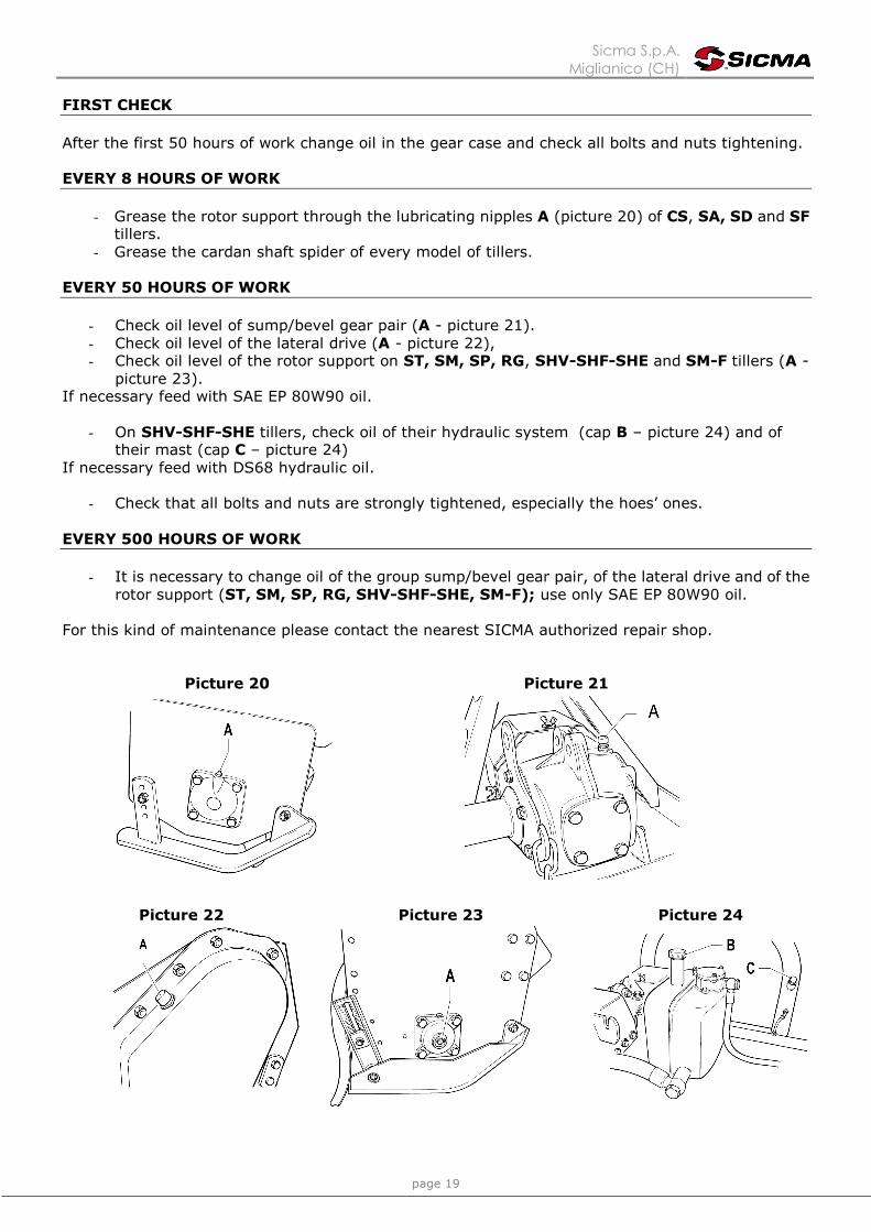
FIRST CHECK After the first 50 hours of work change oil in the gear case and check all bolts and nuts tightening. EVERY 8 HOURS OF WORK
- Grease the rotor support through the lubricating nipples A (picture 20) of CS, SA, SD and SF
tillers. - Grease the cardan shaft spider of every model of tillers.
EVERY 50 HOURS OF WORK
- Check oil level of sump/bevel gear pair (A - picture 21). - Check oil level of the lateral drive (A - picture 22), - Check oil level of the rotor support on ST, SM, SP, RG, SHV-SHF-SHE and SM-F tillers (A -
picture 23). If necessary feed with SAE EP 80W90 oil.
- On SHV-SHF-SHE tillers, check oil of their hydraulic system (cap B – picture 24) and of their mast (cap C – picture 24)
If necessary feed with DS68 hydraulic oil.
- Check that all bolts and nuts are strongly tightened, especially the hoes’ ones. EVERY 500 HOURS OF WORK
- It is necessary to change oil of the group sump/bevel gear pair, of the lateral drive and of the
rotor support (ST, SM, SP, RG, SHV-SHF-SHE, SM-F); use only SAE EP 80W90 oil.
For this kind of maintenance please contact the nearest SICMA authorized repair shop.
Picture 20 Picture 21
Picture 22 Picture 23 Picture 24

Sicma S.p.A. Miglianico (CH)
page 20
Get rid of exhaust oil in compliance with the relevant rules of the country where you operate. It is thus forbidden to pour it on the ground.
Before executing maintenance activities on the machine, stop engine, disengage power takeoff, pull parking brake and place the equipment on the ground.
HOES REPLACEMENT To assure a perfect functioning of the machine, check often that its hoes are in good condition and perfectly fixed by the locking bolts; in case they are broken or bent replace them with new spare parts, remembering to keep always the original position. CS, ST, SM, SP, RG, SF, SD, SHV-SHF-SHE and SM-F tillers are equipped with 6 hoes per flange; on CS, ST and SM models it is possible to reduce their number to 4 when particular soil conditions require this modification.
Before starting the hoes replacement activities, stop engine, pull parking brake and disengage power takeoff; lift then the tiller with the tractor elevator and place it on supports to avoid an accidental fall.
Pay attention to hoes bolts A (picture 25): these ones must be assembled with their screwhead on the hoes side and their washer and nut on the flange side; bolts, thus, will not unscrew while the machine is being used. If you have to replace a sequence of more than one hoe, do it one by one in order to keep as better as you can the original helical-run position (picture 26).
Picture 25 Picture 26
Sicma S.p.A. Miglianico (CH)
page 21
SPARE PARTS ORDERING To order spare parts, please consult the catalogue. Request of spare parts must be made to the retailer or to the nearest service centre and must always be completed with the following information:
- Type and width of the equipment.
- Code number of the needed spare part. Lack of this number, you can replace it with the number of the table where the part is represented and the correspondent reference.
- Denomination of the needed part and desired quantity.
- Chosen transportation. When this item is not specified, the retailer or service centre, even
devoting many cares to this service, do not answer for eventual shipping delays due to acts of God. Transport charges must always be paid by the addressee.

Sicma S.p.A. Miglianico (CH)
page 22

Sicma S.p.A. Miglianico (CH)
page 23

Sicma S.p.A. Miglianico (CH)
page 24