Embed Size (px)
Citation preview
1
Water-Cooled Thorium Breeder Reactors
The 3rd Working Group on Thorium Fuel Utilization
in Light Water and Fast Reactors
WG
Sidik Permana
Nuclear Nonproliferation Science and technology Center (NPSTC)
Japan Atomic Energy Agency (JAEA)
1
2
Possible trends for the contribution of different sources to
total energy supply in the next centuries
Reference : Presented paper,
Contribution of Coal and
Nuclear to Sustainable Energy
Supply: Perspectives and
Problems, President’s meeting of
G8 countries, Brazil, China,
India and South Africa, Moscow
2006
Estimated Energy Sources
2
WG
Sidik Permana,

3
Estimated Energy SourcesWG
Sidik Permana,
4
Estimated Energy SourcesWG
Sidik Permana,

5
Reasonably Assured Reserves (RAR) and Estimated Additional Reserves (EAR) of thorium comes from
OECD/NEA, Nuclear Energy, "Trends in Nuclear Fuel Cycle", Paris, France (2001):
Country RAR Th (tonnes) EAR Th (tonnes)
Brazil 606,000 700,000
Turkey 380,000 500,000
India 319,000 —
United States 137,000 295,000
Norway 132,000 132,000
Greenland 54,000 32,000
Canada 45,000 128,000
Australia 19,000 —
South Africa 18,000 —
Egypt 15,000 309,000
Other Countries 505,000 —
World Total 2,230,000 2,130,000
Resources of Nuclear FuelWG
Sidik Permana,
6
Neutron regeneration ratio of each nuclide as a function of neutron energy
Refference : L. Michael and G. Otto, 1998
233U
239Pu
Possible Breeding of Each
Fissile Material
6
WG
Sidik Permana,

7
235U 236U 237U 238U
239Np
238Pu 239Pu 240Pu 241Pu 242Pu
241Am
242mAm
243Am
242gAm
242Cm 243Cm 244Cm 245Cm 246Cm
237Np
236Pu
236gNp
232U 233U 234U
231Pa
230Th 232Th
233Pa
IT
-decay
EC
(n, ) (n,2n)
decay
Th
Pa
U
Np
Pu
Am
Cm
Th-U Cycle
U-Pu Cycle
Nuclide Chain Mechanism
7
WG
Sidik Permana,
8
Water-Cooled Thorium Breeder Reactors
Content of Presentation
8
1. MOX fuel behavior on Water coolant reactors
2. Comparative analysis on physical properties of
water coolant reactor for different fuel
3. Feasibility analysis on water-cooled breeder
reactor
4. Feasibility analysis on water-cooled breeder
reactor with MA doping as supply fuel
5. Core design analysis on water-cooled breeder
reactor
WG
Sidik Permana,

9
Water-Cooled Thorium Breeder Reactors
MOX fuel properties of Water Cooled
Reactors
9
WG
Sidik Permana,
10
MOX Fuel Behavior [1]WG
Sidik Permana,
Na
Void
Ref : - Hibi and Sekimoto / Journal of nucl. Science and technol, Vol. 42, No. 2, p. 153–160 (2005)
H2O
D2O Na
MOX Fuel
Neutron Spectrum for diff. coolants Plutonium Composition [wt %]
Hard Spectrum : Void>Na>D2O>H2O Fissile Content (X/HM<2):Na<H2O<D2O
11
WG
Sidik Permana,
Ref : - Hibi and Sekimoto / Journal of nucl. Science and technol, Vol. 42, No. 2, p. 153–160 (2005)
H2O
D2O
Na
H2O
D2O
Na
MOX Fuel Behavior [2]
High BR : Na>D2O>H2O Less Void (X/HM<2):Na<H2O<D2O
Breeding Ratio Profile Void Reactivity Coefficient
12
Water-Cooled Thorium Breeder Reactors
Comparative Analysis on Physical
Properties of Water Cooled Reactors
12
WG
Sidik Permana,

13
ReprocessingReactors
H2O/D2O
Coolants
Fabrication
U-233/All HM
Pu/All HM
U
Th
Supply
Storage
WG
Sidik Permana,
Fuel Cycle Options
Supply Fuel : Natural Uranium or Thorium
Recycled Fuel : Plutonium or U-233 or All Heavy Metals (HM)
Physical Parameters : Neutron Spectrum, Eta-value
Investigated Parameters : Required Enrichment, Breeding
and void reactivity coefficient
Others
140.001
0.01
0.1
1
10
100
0.001 0.1 10 1000 105
107
Re
lati
ve N
eu
tro
n S
pe
ctr
a p
erl
eth
arg
y[#
/cm
2s
]
Energy [eV]
D2O
H2O
MFR : Moderator to Fuel Ratio
- D2O harder than H2O
- Very small thermal peak of
D2O, shifts to higher energy.
Neutron Spectrum :
Light water Coolant (H2O) and
Heavy Water Coolant (D2O) at
MFR =2
WG
Sidik Permana,
Neutron Spectrum[2]

15
WG
Sidik Permana,
Neutron Spectrum[4]
H2O coolant , MFR: 0.1 – 1.6
à Low energy region < 1 keV.
H2O coolant
à High energy region > 1 keV.
Ref : - S. Permana et al. / Journal of nucl. Science and technol, Vol. 44, No. 7, p. 946–957 (2007)
16
WG
Sidik Permana,
Neutron Spectrum[4]
0.01
0.1
1
10
100
0.01 1 100 104
106
Rela
tive
Neu
tro
n S
pec
tra p
erl
eth
arg
y[#
/cm
2s
]
Energy [eV]
MFR=20
0.1
0.5
28.0
8.0
MFR=20
D2O Coolant
Harder
Spectrum è
Less MFR
Neutron Spectrum :
Heavy Water Coolant (D2O)
for several MFR
D2O coolant : MFR = 0.1 - 20

17
WG
Sidik Permana,
10-5
10-4
10-3
10-2
100
102
104
106
Re
lati
ve
Ne
utr
on
Sp
ec
tra
[1
/le
tha
rgy
]
Nuetron Energy [eV]
U-Pu, D2O
Th-233U, D2O
U-Pu, H2O
Th-233U, H2
O
10-5
10-4
10-3
10-2
100
102
104
106
Re
lati
ve
Ne
utr
on
Sp
ec
tra
[1
/le
tha
rgy
]
Nuetron Energy [eV]
U-Pu, D2O
Th-233U, D2O
U-Pu, H2O
Th-233U, H2
O
Neutron Spectrum[3]
MFR=2
H2O and D2O Coolants for different fuels
Thorium fuel shows softer than U-Pu
fuel for both water coolants
18
WG
Sidik Permana,
Eta Value [1]
H2O coolant, MFR : 0 – 1.6
D2O coolant, MFR : 0 – 30
Eta value of U-233 à
superior than other
fissile materials

19
1.6
1.8
2
2.2
2.4
0
0.02
0.04
0.06
0.08
0.1
0 0.5 1 1.5 2
Eta
[-]
Eta
of 2
32T
h [-]
Moderator to Fuel Ratio (MFR) [-]
6 GWd/t
Eta Value [2]
Eta value of U-233 à
superior than other
fissile materials and
almost constant along
the MFR
WG
Sidik Permana,
D2O coolant, MFR : 0.1 – 2
20
1.6
1.7
1.8
1.9
2
2.1
2.2
2.3
0 0.5 1 1.5 2 2.5 3 3.5 4
Eta
-Valu
e[-
]
MFR[-]
233U-D2O
WG
Sidik Permana,
Eta Value [3]
H2O and D2O Coolants for different fuels
Eta value of U-233 à
superior than other fissile
materials along the MFR

21
0
2
4
6
8
10
0 1 2 3 4 5
En
ric
hm
en
t U
235 o
r U
233 [
%]
Moderator to Fuel Ratio[-]
U-Pu, H2O
Th- 233U, H2O
U-Pu, D2O
Th- 233U, D2O
0
2
4
6
8
10
0 1 2 3 4 5
En
ric
hm
en
t U
235 o
r U
233 [
%]
Moderator to Fuel Ratio[-]
U-Pu, H2O
Th- 233U, H2O
U-Pu, D2O
Th- 233U, D2O
0.5
0.6
0.7
0.8
0.9
1
1.1
1.2
0 1 2 3 4 5
Co
nv
ers
ion
Ra
tio
[-]
Moderator to Fuel Ratio[-]
U-Pu, H2O
Th- 233U, H2O
U-Pu, D2O
Th- 233U, D2O
Breeding line
0.5
0.6
0.7
0.8
0.9
1
1.1
1.2
0 1 2 3 4 5
Co
nv
ers
ion
Ra
tio
[-]
Moderator to Fuel Ratio[-]
U-Pu, H2O
Th- 233U, H2O
U-Pu, D2O
Th- 233U, D2O
Breeding line
Fissile Content and Conversion RatioWG
Sidik Permana,
H2O and D2O Coolants for different fuels
Required Fissile Content Conversion Ratio
22
-2
-1.5
-1
-0.5
0
0.5
1
1.5
0 1 2 3 4 5
Vo
id R
ea
cti
vit
y x
1e
-3[d
k/k
/%v
ol]
Moderator to Fuel Ratio[-]
Th- 233U, H2O
Th- 233U, D2O
Void Reactivity CoefficientWG
Sidik Permana,
Negative Void Coefficient
-MOX_D2O : Always Positive
-MOX_H2O : Negative 1<MFR<3.4)
-Th_U233_D2O : Negative for MFR>0.4
-Th_U233_H2O : Negative for MFR<1.4
36 GWd/t

23
Water-Cooled Thorium Breeder Reactors
Feasibility Analysis on Water-Cooled
Breeder Reactor
23
WG
Sidik Permana,
24
ReprocessingReactors
H2O/D2O
Coolants
Fabrication
U-233/All HM
Th
Supply
Storage
WG
Sidik Permana,
Fuel Cycle Options
Supply Fuel : Thorium
Recycled Fuel : U-233 or All Heavy Metals (HM)
Physical Parameters : Neutron Spectrum, Eta-value
Investigated Parameters : Required Enrichment, Breeding
and void reactivity coefficient

25
Ref : - S. Permana et al. / Journal of nucl. Science and technol, Vol. 44, No. 7, p. 946–957 (2007)
- Global, 2007
Negative void
coefficient
Feasible area of breeding and
negative void coefficient
H2O
coolant
Void coefficient profile
Light water coolant à
Shows A feasible design area for
breeding and negative void reactivity
coefficient
Feasible Breeding and Negative Void Reac.WG
Sidik Permana,
26
Ref : - S. Permana et al. / Journal of nucl. Sciece and technol, Vol. 45, No. 7, p. 589–600 (2008)
- Global, 2007
A feasible design of breeding and
negative void coefficientVoid coefficient Profile
2O
coolant
Feasible Breeding and Negative Void Reac.WG
Sidik Permana,

27
Ref :
- S. Permana et al. / Journal of nucl. Sciece and technol, Vol. 45, No. 7, p. 589–600 (2008)
- S. Permana et al. / Journal of nucl. Sciece and technol, Vol. 44, No. 7, p. 946–957 (2007)
- Global, 2007
Output : 3GWtCore Hight : 3.7m
D2O-cooled breeder reactor
- MFR=1
- Pellet power density of 140W/cc
- Burn-up of 50 GWd/t.
Wider feasible
window of breeding
for D2O-cooled
2O
coolant
2O
coolant
Comparative H2O and D2O CoolantsWG
Sidik Permana,
28
Comparative U-233 and All HM closed CycleWG
Sidik Permana,
U-233 Closed Cycle All HM Closed Cycle
Ref :
- S. Permana et al. / Annals of Nuclear Energy, Accepted, 2010
D2O Coolant
29
Comparative U-233 and All HM closed CycleWG
Sidik Permana,
Ref :
- S. Permana et al. / Annals of Nuclear Energy, Accepted, 2010
D2O Coolant
Conversion ratio :
U-233 closed > HM closed
for MFR > 0.5
Breeding ratio :
U-233 closed : MFR < 1.5
All HM closed : MFR > 1.2
Void coefficient :
U-233 closed less void
coefficient than All HM closed
30
Comparative U-233 and All HM closed CycleWG
Sidik Permana,
Ref :
- S. Permana et al. / Annals of Nuclear Energy, Accepted, 2010
Heavy water coolant for both
U-233 only recycling and All
HM recycling options à
Shows A feasible design area
for breeding and negative void
reactivity coefficient
U-233 only recycling case
obtains wider feasible design
area for breeding and negative
void reactivity coefficient than
All HM closed cycle.

31
Water-Cooled Thorium Breeder Reactors
Feasibility Analysis on Water-Cooled
Breeder Reactor with MA doping
31
WG
Sidik Permana,
32
ReprocessingReactors
H2O/D2O
Coolants
Fabrication
All HM
Th
Supply
Storage
WG
Sidik Permana,
Fuel Cycle Options
Supply Fuel : Thorium
Recycled Fuel : U-233 or All Heavy Metals (HM)
Investigated Parameters : Required Enrichment, Breeding
and void reactivity coefficient
MA

33
Conversion Ratio
By doped MA, the breeding capabilities
are improved. Higher breeding for Higher
MA doped.
- Conversion ratio monotonically
decreases with increasing burnup.
- Breeding can be achieved for burnup <
45 GWd/t.
WG
Sidik Permana,
Effect of MA content (%) Effect of Burnup
34
- Breeding capability monotonically
decreases with increasing MFR.
- Breeding can be achieved for MFR < 1.1
- Breeding capability monotonically
increases with decreasing power
density (PD) of fuel pellet.
-Breeding can be achieved for fuel
pellet PD ≤ 200 W/cc.
Conversion Ratio
Effect of MFR Effect of Power Density
WG
Sidik Permana,

35
Water-Cooled Thorium Breeder Reactors
Core Design Analysis on Water-Cooled
Breeder Reactor
35
WG
Sidik Permana,
36
-Refueling modes : Once Through
methods.
- Three batches core configuration
systems.
- Preliminary Thermal Hydraulic
Analysis.
Evaluate the reactor core performances and fuel management by using
core burnup of SRAC COREBN calculations which adopted 2-dimensional
hexagonal model as the core fuel configuration.
- Basic Reactor : Heavy water
cooled thorium reactors
- Core configuration : Refers to
optimum result of equilibrium
cycle iterative calculation systems
(ECICS)
Objectives and Evaluation
- Fuel Breeding Capability and Reactor Criticality
- Negative void reactivity coefficient. -
Thermal Hydraulic Properties comparable to PWR.
WG
Sidik Permana,

371
2
3
4
5
6
7
8
0.8
0.9
1
1.1
1.2
1.3
1.4
1.5
0 0.2 0.4 0.6 0.8 1 1.2 1.4 1.6 1.8 2
6 GWd/t
18
36
50
En
rich
me
nt
233U
Co
nve
rsio
n R
atio
[-]
MFR[-]
Burnup
decreases
Required enrichment and Conversion ratio
High burnup à High
required enrichment or
fissile content, except
for very low MFR with
less moderator
High burnup à less
conversion ratio
(higher consumption
ratio of fissile)
WG
Sidik Permana,
38-40
-30
-20
-10
0
10
0 0.2 0.4 0.6 0.8 1 1.2 1.4 1.6 1.8 2
6 GWd/t
18
36
50
Vo
id R
eac
tiv
ity C
oef.
x1
0e
-3[d
k/k
/%v
ol]
MFR[-]
Burnup
increases
50% void
Void Reactivity Coefficient
High burnup à Less
void reactivity
coefficient or becomes
positive void.
High MFR à High Void
reactivity coefficient
WG
Sidik Permana,
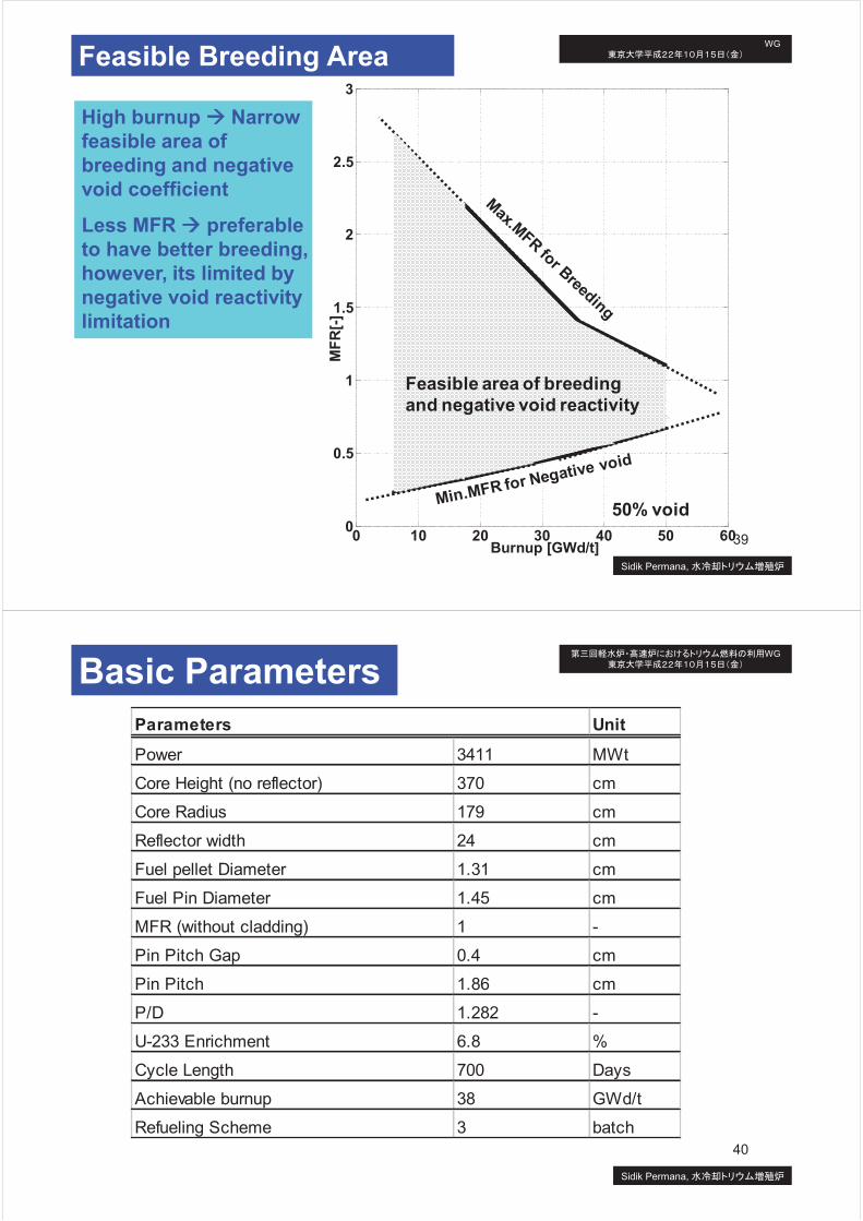
390
0.5
1
1.5
2
2.5
3
0 10 20 30 40 50 60
MF
R[-
]
Burnup [GWd/t]
50% void
Feasible area of breeding
and negative void reactivity
Feasible Breeding Area
High burnup à Narrow
feasible area of
breeding and negative
void coefficient
Less MFR à preferable
to have better breeding,
however, its limited by
negative void reactivity
limitation
WG
Sidik Permana,
40
Unit
Power MWt
Core Height (no reflector) cm
Core Radius cm
Reflector width cm
Fuel pellet Diameter cm
Fuel Pin Diameter cm
MFR (without cladding) -
Pin Pitch Gap cm
Pin Pitch cm
P/D -
U-233 Enrichment %
Cycle Length Days
Achievable burnup GWd/t
Refueling Scheme batch
0.4
1.86
1.282
Parameters
3411
370
179
700
38
3
24
1.31
1.45
6.8
1
Basic Parameters WG
Sidik Permana,

41
Calculation Schemes
Rf
Rcl
Rco
Rf
Rcl
Rco
Fuel Pin
Fuel Assembly
Rf : Radius of fuel
Rcl : Radius of cladding
Rco : Radius of coolant
Core 1
Core 2
Core 3Out-In
Mode
Fresh
Fuel
Core 1
Core 2
Core 3
Core 1
Core 2
Core 3Out-In
Mode
Fresh
Fuel
Core 1
Core 2
Core 3In-Out
Mode
Fresh
Fuel
Core 1
Core 2
Core 3
Core 1
Core 2
Core 3In-Out
Mode
Fresh
Fuel
Out-In Shuffling Scheme
In-Out Shuffling Scheme
41
WG
Sidik Permana,
42
Criticality and Breeding Profiles
0.95
1
1.05
1.1
0 500 1000 1500 2000Operation Time [Days]
K-EFF
Conversion Ratio
Out-in Method
700 Days 700 Days 700 Days
Cycle Length : 700 Days
Fuel Core Batches : 3 Batches
Criticality (K-Eff) : Decreases with
Reactor Operation Time
Breeding (Conversion Ratio):
Increases with Operation Time
At BOC : Breeding à less than unity
At EOC : Breeding à High than unity
Achievable Discharged Fuel Burnup:
More than 33 GWd/t
Out In Method :
àLess criticality for next recycling step
àConversion ratio starts from less than
unity at BOC and reaches higher than
unity at EOC.
àIt confirmed breeding can be achieved
42
WG
Sidik Permana,

43
Criticality and Breeding Profiles
0.95
1
1.05
1.1
0 500 1000 1500 2000Operation Time [Days]
K-E
FF
Conversion Ratio
In-Out Method
700 Days 700 Days 700 Days
Cycle Length : 700 Days
Fuel Core Batches : 3 Batches
Criticality (K-Eff) : Decreases with
Reactor Operation Time
Breeding (Conversion Ratio):
Increases with Operation Time
Out In Method :
àIt confirmed breeding can be achieved
Breeding (Conversion Ratio):
In-Out Method : 1.01
Out-In Method : 1.02
WG
Sidik Permana,
44
Void Reactivity Coefficient
-300
-250
-200
-150
-100
-50
0
50
100
0 500 1000 1500 2000
5% void fraction100%
Vo
id R
ea
cti
vit
y C
oe
ffic
ien
t [p
cm
]
Burnup[Days]
Out-in Method
-300
-250
-200
-150
-100
-50
0
50
100
0 500 1000 1500 2000
5% void fraction100%
Vo
id R
ea
cti
vit
y C
oe
ffic
ien
t [p
cm
]
Burnup[Days]
In-Out Method
Void reactivity coefficient :
à Always negative during reactor operation
à Higher void fraction : less negative at EOC
Void reactivity coefficient :
à Voided fraction effect : low for out-in
method and higher for in-out method44
WG
Sidik Permana,

45
Temperature Distribution
250
300
350
400
450
0 50 100 150 200 250 300 350 400Axial Direction from bottom to top [cm]
Coolant Flow
Cladding Surface
Out-In Method
Temperature [C]
250
300
350
400
450
0 50 100 150 200 250 300 350 400Axial Direction from bottom to top [cm]
Coolant Flow
Cladding Surface
In-Out Method
Temperature [C]
Temperature :
à Maximum Temp. cladding surface : Out-
In : Less 400 C, In-out : reaches 400 C
Temperature:
à Out-in method : Relatively Higher
temperature than In-out method45
WG
Sidik Permana,
46
Temperature Distribution
300
350
400
450
0 50 100 150 200 250 300 350 400Axial Direction from bottom to top [cm]
Out-in Method
In-out Method
Temperature of Cladding Surface [C]
1000
1100
1200
1300
1400
1500
1600
1700
1800
0 50 100 150 200 250 300 350 400Axial Direction from bottom to top [cm]
Out-in Method
In-out Method
Temperature of Fuel Center-line [C]
46
WG
Sidik Permana,

47
Power Peaking Profile
0.5
1
1.5
2
2.5
0 400 800 1200 1600 2000 2400
Out-In MethodIn-Out Method
Po
wer
Peakin
g [
-]
Burnup[Days]
Power peaking : Ratio of maximum
power density to the average power
density
- Out-In Method : decreases for the
next recycling step
- In-Out Method : increases for nex
recycling step
- Out-in method : less than 1.5
- In-Out Method : reaches more than
2
Power peaking profile shows the
maximum different of power at a
certain location to the average total
power distribution.
WG
Sidik Permana,
48
Thermal Hydraulic Properties
Unit
Tinlet 300 °C
Toutlet 332 °C
Average Thermal Conductivity of TH 2.75 W/m K
Average Thermal Conductivity of Zr- 10.7 W/m K
Themal Conductivity of Heavy water 0.483 W/m K
Specific heat capacity of Heavy water 4228 J/Kg K
Fuel Area 1.66E-04 m2
Volume of Fuel 6.12E-04 m3
Coolant Area 1.08E-04 m2
Max Power density of Core 1.10E+08 W/m3
Fluid Density 720 Kg/m3
P/D 1.28 -
Hydraulic Diameter 0.0118 m
Heat Flux clad surface 4.07E+05 W/m2
Parameters Unit
Mean flow velocity 4.14 m/s
Renoylds number 2.80E+04
Prandtl number 10.94 -
Heat Trannsfer 2.85E+04 W/m2 K
Fanin Friction 6.11E-03
Friction Pressure drop 0.47 bar
Fuel Temperature Drop 526 C
Total Temperature drop 679 C
Maximum Coolant Temperature 332 C
Maximum Fuel Temperature 1058 C
Thermal hydraulic parameter
Out-in Method
WG
Sidik Permana,

49
Thermal Hydraulic Properties
Unit
Tinlet 300 °C
Toutlet 332 °C
Average Thermal Conductivity of TH 2.75 W/m K
Average Thermal Conductivity of Zr- 10.7 W/m K
Themal Conductivity of Heavy water 0.483 W/m K
Specific heat capacity of Heavy water 4228 J/Kg K
Fuel Area 1.66E-04 m2
Volume of Fuel 6.12E-04 m3
Coolant Area 1.08E-04 m2
Max Power density of Core 2.11E+08 W/m3
Fluid Density 720 Kg/m3
P/D 1.28 -
Hydraulic Diameter 0.0118 m
Heat Flux clad surface 7.66E+05 W/m2
Parameters Unit
Mean flow velocity 7.79 m/s
Renoylds number 5.28E+04
Prandtl number 10.94 -
Heat Trannsfer 5.38E+04 W/m2 K
Fanin Friction 5.22E-03
Friction Pressure drop 1.43 bar
Fuel Temperature Drop 1008 C
Total Temperature drop 1303 C
Maximum Coolant Temperature 332 C
Maximum Fuel Temperature 1704 C
Thermal hydraulic parameter
In-Out Method
WG
Sidik Permana,
50
Conclusion
1. Core burnup calculations have confirmed that breeding is
feasible for water cooled thorium reactor system. It also
confirmed that negative void reactivity coefficients are
obtained during reactor operation.
2. Fuel breeding capabilities have been shown 1.01 (Out-In
method) and 1.02 (In-Out method) at the end of cycle.
3. Thermal hydraulic parameters show the comparable
result with conventional reactors and have the large
margin to the limitation of thermal hydraulic properties.
4. Reactor core optimization for neutronic and thermal
hydraulic aspects should be done for future investigation
WG
Sidik Permana,

51
END OF PRESENTATION
Thank You
Questions or
comments?
WG
Sidik Permana,