Embed Size (px)
Citation preview
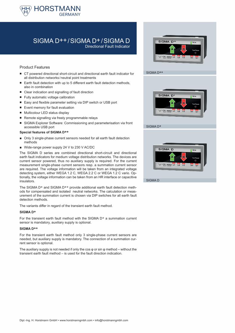
SIGMA D++
SIGMA D
SIGMA D+
Dipl.-Ing. H. Horstmann GmbH ▪ www.horstmanngmbh.com ▪ [email protected]
Product Features ■ CT powered directional short-circuit and directional earth fault indicator for
all distribution networks / neutral point treatments ■ Earth fault detection with up to 5 different earth fault detection methods,
also in combination ■ Clear indication and signalling of fault direction ■ Fully automatic voltage calibration ■ Easy and flexible parameter setting via DIP switch or USB port ■ Event memory for fault evaluation ■ Multicolour LED status display ■ Remote signalling via freely programmable relays ■ SIGMA Explorer Software: Commissioning and parameterisation via front
accessible USB portSpecial features of SIGMA D++
■ Only 3 single-phase current sensors needed for all earth fault detection methods
■ Wide-range power supply 24 V to 230 V AC/DCThe SIGMA D series are combined directional short-circuit and directional earth fault indicators for medium voltage distribution networks. The devices are current sensor powered, thus no auxiliary supply is required. For the current measurement single-phase current sensors resp. a summation current sensor are required. The voltage information will be taken from an integrated voltage detecting system, either WEGA 1.2 C, WEGA 2.2 C or WEGA 1.2 C vario. Op-tionally, the voltage information can be taken from an HR interface or capacitive insulators.
The SIGMA D+ and SIGMA D++ provide additional earth fault detection meth-ods for compensated and isolated neutral networks. The calculation or meas-urement of the summation current is chosen via DIP switches for all earth fault detection methods.
The variants differ in regard of the transient earth fault method.
SIGMA D+
For the transient earth fault method with the SIGMA D+ a summation current sensor is mandatory, auxiliary supply is optional.
SIGMA D++
For the transient earth fault method only 3 single-phase current sensors are needed, but auxiliary supply is mandatory. The connection of a summation cur-rent sensor is optional.
The auxiliary supply is not needed if only the cos φ or sin φ method – without the transient earth fault method – is used for the fault direction indication.
SIGMA D++ / SIGMA D+ / SIGMA DDirectional Fault Indicator
Technical Data SIGMA D SIGMA D+ SIGMA D++Detection of short-circuit and earth fault direction
▪ ▪ ▪
Earth fault detection methods Earth short-circuit Transient, earth short-circuit, cos φ or sin φI>> Short-circuit trip current ▪ DIP: 200, 300, 400, 600, 800, 2,000 A (fixed settings), self-adjustment
▪ SW: 50 – 2,000 A (1 A steps)tI>> Response delay DIP: 40, 80 ms; SW: 40 ms – 60 sIE> Earth fault trip current DIP: off, 20, 40, 60, 80, 100, 120, 160 A; SW: 20 – 1,000 A (1 A steps)tIE> Response delay DIP: 80, 160 ms; SW: 40 ms – 60 sAccuracy 3 % (0 – 630 A, resolution 1 A)
5 % (630 – 1,500 A) 10 % (1,500 – 2,000 A)
IET> Transient method, trip current — 10 – 100 A 10 – 500 AIEP> Active current, cos φ trip current — 5 – 200 AIEQ> Reactive current sin φ, trip current — 5 – 200 AtIEP> / tIEQ> Response delay — 40 ms – 60 sIndication LED fault direction arrows red / greenReset ▪ Manual reset
▪ Remote reset ▪ Automatic time reset: DIP: 2, 4, 8, 24 h; SW: 1 min – 24 h ▪ Current and voltage restoration
Remote signal / Communication 4 potential-free, freely programmable relay contactsParameter setting ▪ USB 2.0 interface, connection to software
▪ Via DIP switchRemote contact 4 permanent or momentary contacts (1 s), NC or NO (adjustable)
Contact capacity: 230 V AC / 1 A / 62.5 VA max.; 220 V DC / 1 A / 60 W max.Voltage calibration Manual / automaticCurrent sensor powered ▪ ▪ ▪ Internal power supply Long-life lithium cell; shelf life ≥20 yearsExternal power supply (auxiliary supply) – 24 V AC / 24 – 60 V DC
optional24 – 230 V AC/DC optional (required for transient method)
Housing Polycarbonate, IP40 (plug-in housing)Temperature range -30 to +70 °C
SIGMA D SIGMA D+ SIGMA D++Equipment set ▪ 1 Display unit (plug-in housing)
▪ 3 Single-phase current sensors ▪ 1 Display unit (plug-in housing) ▪ 3 Single-phase current sensors ▪ 1 Summation current sensor
(required for transient method)
▪ 1 Display unit (plug-in housing) ▪ 3 Single-phase current sensors ▪ 1 Summation current sensor
(optional)
Article Order No.SIGMA D SIGMA D+ SIGMA D++
Display unit in plug-in housing 37-6000-001 37-6100-001 37-6200-001Current sensors see on page 30 and 31Accessories see on page 32 and 33External signal lamp see on page 33
Dipl.-Ing. H. Horstmann GmbH ▪ www.horstmanngmbh.com ▪ [email protected]
Dimension drawing see on page 49, M3
SIGMA D++ / SIGMA D+ / SIGMA DDirectional Fault Indicator
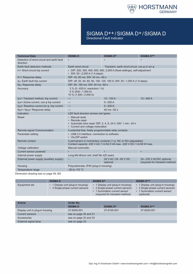
Switchgear Manufacturer1) Type Order No.ABB SafeLink, SafePlus, SafeRing 3x 49-6025-000 or 3x 49-6025-301Driescher MINEX, MINEX C, G.I.S.E.L.A. 3x 49-6025-601*EATON XIRIA 3x 49-6025-000 or 3x 49-6025-301Lucy Electric AegisPlus 3x 49-6025-601Ormazabal GA , GAE, GE 3x 49-6025-311Schneider Electric RM6 3x 49-6025-601Schneider Electric FBX 3x 49-6025-602*Siemens 8DJH (module transformer) 2x 49-6025-611, 1x 49-6025-612
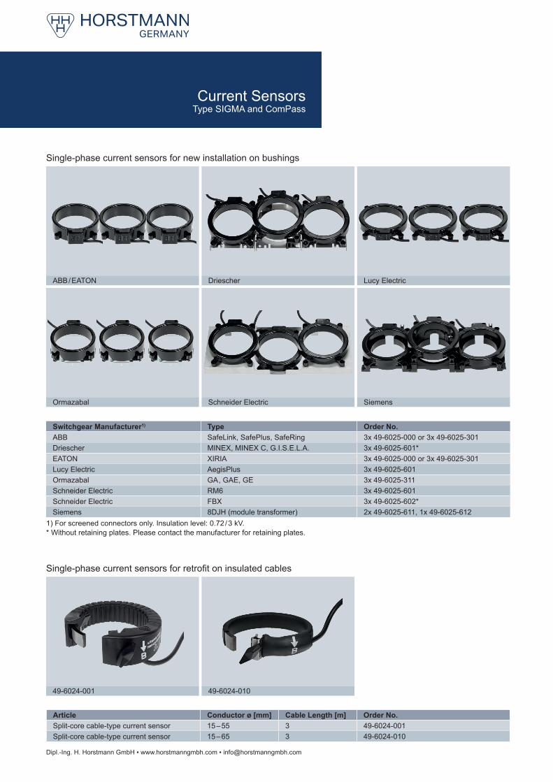
Article Conductor ø [mm] Cable Length [m] Order No.Split-core cable-type current sensor 15 – 55 3 49-6024-001Split-core cable-type current sensor 15 – 65 3 49-6024-010
ABB / EATON Driescher Lucy Electric
Ormazabal Schneider Electric Siemens
49-6024-001 49-6024-010
Dipl.-Ing. H. Horstmann GmbH ▪ www.horstmanngmbh.com ▪ [email protected]
1) For screened connectors only. Insulation level: 0.72 / 3 kV.
Single-phase current sensors for new installation on bushings
Single-phase current sensors for retrofit on insulated cables
* Without retaining plates. Please contact the manufacturer for retaining plates.
Current SensorsType SIGMA and ComPass
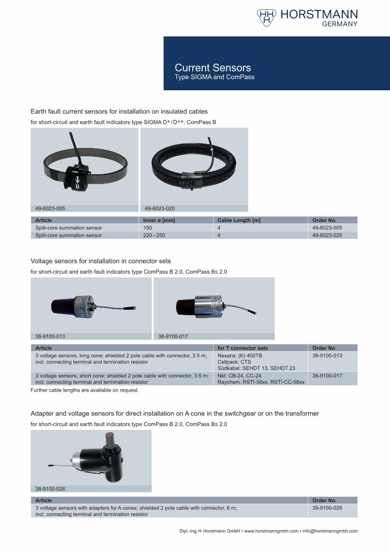
Article Inner ø [mm] Cable Length [m] Order No.Split-core summation sensor 150 4 49-6023-005Split-core summation sensor 220 – 250 4 49-6023-020
Article for T connector sets Order No.3 voltage sensors, long cone; shielded 2 pole cable with connector, 3.5 m; incl. connecting terminal and termination resistor
Nexans: (K) 400TB Cellpack: CTS Südkabel: SEHDT 13, SEHDT 23
38-9100-013
3 voltage sensors, short cone; shielded 2 pole cable with connector, 3.5 m; incl. connecting terminal and termination resistor
Nkt: CB-24, CC-24 Raychem: RSTI-58xx, RSTI-CC-58xx
38-9100-017
Article Order No.3 voltage sensors with adapters for A cones; shielded 2 pole cable with connector, 6 m; incl. connecting terminal and termination resistor
38-9100-026
49-6023-005 49-6023-020
38-9100-026
38-9100-013 38-9100-017
Dipl.-Ing. H. Horstmann GmbH ▪ www.horstmanngmbh.com ▪ [email protected]
Earth fault current sensors for installation on insulated cablesfor short-circuit and earth fault indicators type SIGMA D+ / D++, ComPass B
Voltage sensors for installation in connector setsfor short-circuit and earth fault indicators type ComPass B 2.0, ComPass BS 2.0
Adapter and voltage sensors for direct installation on A cone in the switchgear or on the transformerfor short-circuit and earth fault indicators type ComPass B 2.0, ComPass BS 2.0
Further cable lengths are available on request.
Current SensorsType SIGMA and ComPass
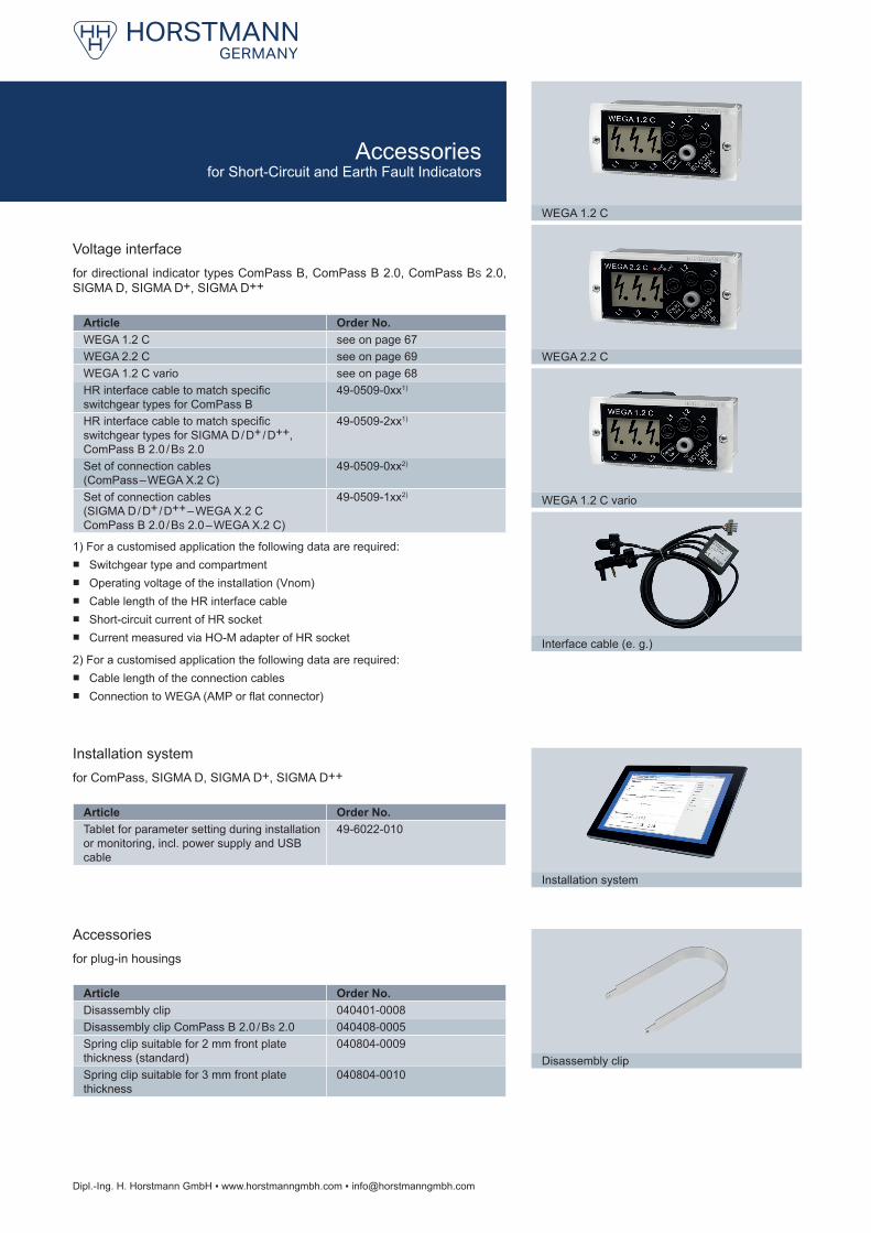
Article Order No.WEGA 1.2 C see on page 67WEGA 2.2 C see on page 69WEGA 1.2 C vario see on page 68HR interface cable to match specific switchgear types for ComPass B
49-0509-0xx1)
HR interface cable to match specific switchgear types for SIGMA D / D+ / D++, ComPass B 2.0 / BS 2.0
49-0509-2xx1)
Set of connection cables (ComPass – WEGA X.2 C)
49-0509-0xx2)
Set of connection cables (SIGMA D / D+ / D++ – WEGA X.2 C ComPass B 2.0 / BS 2.0 – WEGA X.2 C)
49-0509-1xx2)
Article Order No.Tablet for parameter setting during installation or monitoring, incl. power supply and USB cable
49-6022-010
Article Order No.Disassembly clip 040401-0008Disassembly clip ComPass B 2.0 / BS 2.0 040408-0005Spring clip suitable for 2 mm front plate thickness (standard)
040804-0009
Spring clip suitable for 3 mm front plate thickness
040804-0010
WEGA 1.2 C
Installation system
Interface cable (e. g.)
WEGA 1.2 C vario
WEGA 2.2 C
Disassembly clip
Dipl.-Ing. H. Horstmann GmbH ▪ www.horstmanngmbh.com ▪ [email protected]
Voltage interfacefor directional indicator types ComPass B, ComPass B 2.0, ComPass BS 2.0, SIGMA D, SIGMA D+, SIGMA D++
Installation systemfor ComPass, SIGMA D, SIGMA D+, SIGMA D++
Accessoriesfor plug-in housings
1) For a customised application the following data are required: ■ Switchgear type and compartment ■ Operating voltage of the installation (Vnom) ■ Cable length of the HR interface cable ■ Short-circuit current of HR socket ■ Current measured via HO-M adapter of HR socket
2) For a customised application the following data are required: ■ Cable length of the connection cables ■ Connection to WEGA (AMP or flat connector)
Accessories for Short-Circuit and Earth Fault Indicators
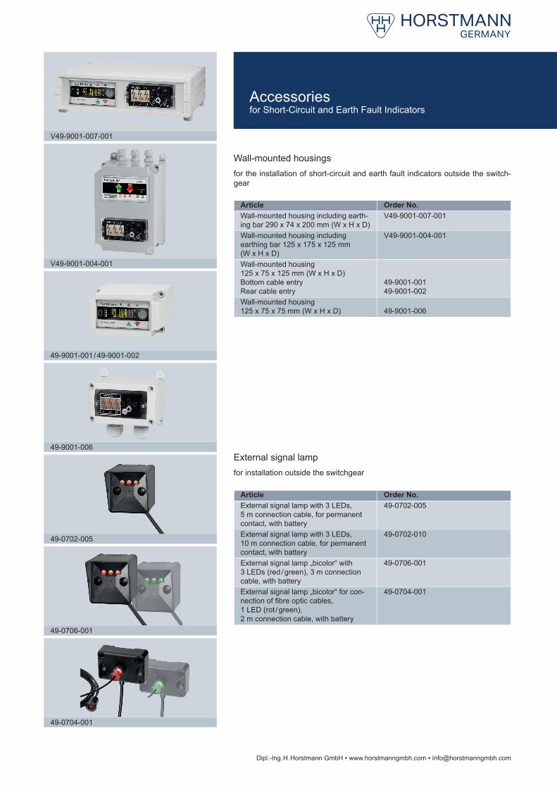
Article Order No.Wall-mounted housing including earth-ing bar 290 x 74 x 200 mm (W x H x D)
V49-9001-007-001
Wall-mounted housing including earthing bar 125 x 175 x 125 mm (W x H x D)
V49-9001-004-001
Wall-mounted housing 125 x 75 x 125 mm (W x H x D) Bottom cable entry Rear cable entry
49-9001-001 49-9001-002
Wall-mounted housing 125 x 75 x 75 mm (W x H x D) 49-9001-006
Article Order No.External signal lamp with 3 LEDs, 5 m connection cable, for permanent contact, with battery
49-0702-005
External signal lamp with 3 LEDs, 10 m connection cable, for permanent contact, with battery
49-0702-010
External signal lamp „bicolor“ with 3 LEDs (red / green), 3 m connection cable, with battery
49-0706-001
External signal lamp „bicolor“ for con-nection of fibre optic cables, 1 LED (rot / green),2 m connection cable, with battery
49-0704-001
V49-9001-007-001
49-0704-001
49-0706-001
49-0702-005
49-9001-006
49-9001-001 / 49-9001-002
V49-9001-004-001
Dipl.-Ing. H. Horstmann GmbH ▪ www.horstmanngmbh.com ▪ [email protected]
Wall-mounted housingsfor the installation of short-circuit and earth fault indicators outside the switch-gear
External signal lampfor installation outside the switchgear
Accessoriesfor Short-Circuit and Earth Fault Indicators


![Six Sigma (6 Sigma)[1]](https://img.pdfslide.tips/doc/110x75/577d35cc1a28ab3a6b91711a/six-sigma-6-sigma1.jpg)