Embed Size (px)
Citation preview

Signaling System
1
Reference (1/2)
• [1] Wireless and Mobile Network Architectures,Y-Bing Lin and Imrich Chlamtac,Wiley Computer Publishing。
– Chapters 2 and 5.
• [2] 第七號共通信號系統概論,湯鴻沼,全華科技圖書股份有限公司。
• [3] Telephone Network and PBX Software ,Yi-Bing Lin,維科出版社。
• [4] Mobile and Wireless Networks,Uyless Black,Prentice Hall。Appendix A.
2

Reference (2/2)
• [5] SS7信號系統,林添財,中華電信訓練所教材。
• [6] Carrier Grade Voice over IP,2nd,Daniel Collins,Mc Graw-Hill Companies Inc.。
• [7]Signaling System #7, 2nd, Travis Russell, McGraw-Hill.
3

Outlines
• Introduction
• Signaling System Number 7
• Components and Links of SS7
• SS7 Protocol Stack
• SS7 Messages
• PCS/PSTN Call Control Using ISUP
• Summary
4
Introduction
• PSTN
• SS7 Network Architecture
• SS7 Components

PSTN Architecture
6

Components in PSTN
• Customer premises equipment (CPE)
– Telephone set, PBX (Private Branch Exchanges), ISDN (Integrated Services Digital Network) PBX, ISDN Adaptor
• Transmission facilities
– Trunks and subscriber lines
• Switching system
– Central offices (CO) or exchange, tandems, ISDN CO
7

Call Setup and Release
• A call requires a communications circuit between two subscribers.
• The setup and release of connection is triggered by signals.
8
Signaling Systems (1/2)
• Besides delivering subscriber voice and data information, telecommunication network requires a signaling system.
• Signaling is the communication of control information between the signaling elements via some prescribed protocol.
– For call setup control, administration, disconnect of the circuit
9

Signaling Systems (2/2)
• Two types of signaling functions:
– Supervisory signals – initiate a call request, to hold or release an established connection
• Supervising signals: recognize if subscriber lines/interoffice trunks are busy or idle
• Call progress signals: provide call status information
• Alerting signals: provide warning to a subscriber
– Address signals
10

Customer-Line Signaling
11

Dial Pulse vs. Dual Tone Multi-Frequency
12

Interoffice Trunk Signaling
• Control information exchange among the switches is achieved by interoffice trunk signaling.
• Two approaches:
• Channel associated signaling (CAS)
– Signaling and voice share the same inband channel.
• Common channel signaling (CCS)
– A separate out-of-band signaling network to carry signaling message.
13

CAS v.s. CCS
• Channel Associated Signaling
– Signaling and voice share the same channel
• Common Channel Signaling
– Separation of signaling and call paths
– Signaling System 7 (SS7)
14

The Advantages of CCS
• Signaling packets can be efficiently delivered using signaling links, which reduces the call setup time.
• Since the ineffective call attempts are released by the signaling links, better utilization of voice trunks can be expected.
• Signaling can be performed during conversation.
15

Signaling System No. 7 (1/2)
• The first CCS system is signaling system number 6 developed in the 1970s.
• The modern CCS system is SS7.
• SS7 is the foundation for Intelligent Network (IN) services.
• SS7 is a dedicated data communication network and similar to the packet network.
– SS7 follows OSI 7 layer architecture.
– Message-based signaling protocol
16
Signaling System No. 7 (2/2)
• To enable a wide range of services to be provided to the end-user
• Caller ID, toll-free calling, call screening, number portability, etc.
• Signaling between a PCS network and the PSTN are typically achieved by the SS7 network.
17

Components and Links of SS7

Signaling Point (SP)
• Each node in an SS7 network is an signal point (SP).
• The signaling address of the SP is known as a signaling point code.
• Linkset
– Group of signaling links directly connecting two adjacent SPs
– For capability and security reasons
19

Basic Components
• SSP/Service Switching Point
– switching, service invocation
• STP/Signal Transfer Point
– signal routing
• SCP/Service Control Point
– service logic execution
• IP/Intelligent Peripheral
– resources such as customized voice announcement, voice recognition, DTMF digit collection
20

Service Switching Point (SSP)
• Trunks connects SSPs to carry user data/voice information.
• Signaling links connect SCPs to STPs, and STPs to SSPs.
21

Signal Transfer Point (STP)
22
• To transfer messages from one SPC to another

Service Control Point (SCP)
• A network entity that contains additional logic and that can be used to offer advanced services
• The switch sends a message to the SCP asking for instructions.
– The SCP, based upon data and service logic that is available, will tell the switch which actions need to be taken.
• An good example – toll-free 080 number
23

Typical SS7 Network arrangement
24
• A typical SS7 network arrangement.
• Two switches do not communicate signaling to each other via direct paths.
• The quad arrangement ensures great robustness.

The Telephone Network
25
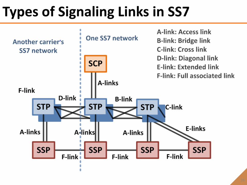
Types of Signaling Links in SS7
26

SS7 Protocol Stack

The SS7 Signaling Protocol
28

Message Transfer Part (1/2)
• MTP Level 1
– Defines the physical, electrical and functional characteristics of the signaling. • 100111010110000011100111001.....
• MTP Level 2
– Dealing with the transfer of messages on a given link from one node to another
– Provides reliable transfer of signaling messages between two directly connected signaling points
– Error detection and correction, flow control, signal unit delimitation, etc.
29

Message Transfer Part (2/2)
• MTP Level 3
– Provides the functions and procedures related to message routing and network management.
• Signaling message handling
– Providing message routing between signaling points in the SS7 network
• Signaling network management
– Rerouting traffic to other SS7 signaling links in the case of link failure, congestion or node failure
– Load-sharing
30

ISUP
• ISDN User Part
• Used as the protocol for setting up and tearing down phone calls between switches
• Initial Address Message (IAM)
– To initiate a call between two switches
• Answer Message (ANM)
– To indicate that a call has been accepted by the called party
• Release Message (REL)
– To initiate call disconnection
31

SCCP
• Signaling Connection Control Part
• Used as the transport layer for TCAP-based services
• Both connection-oriented and connectionless
– Mostly connectionless signaling
• Global title translation (GTT) capabilities
– The destination signaling point and subsystem number is determined from the global title
32

TCAP
• TCAP (Transaction Capabilities Applications Part)
• Supporting the exchange of non-circuit related information between signaling points
• Queries and responses sent between SSPs and SCPs are carried in TCAP messages
• Freephone (800/888), calling card, wireless roaming
33

MAP and OMAP
• Operations, Maintenance, and Administration Part (OMAP)
• Mobile Application Part (MAP)
– Application of TCAP
– IS-41 & GSM MAP are implemented in MAP layer.
34

SS7 Messages

MTP2 Messages
36

ITU-T Message Signal Unit
37

Message Signal Unit (MSU)
38

ISUP Message Format
39

ISUP Message
• ISUP messages
– Establishes circuit-switched network connections
– Call setup/release between the PSTN and a PCN.
• ISUP messages that are delivered by MTP routing.
40

ISUP Messages (1/2)
• IAM (Initial Address Message)
– called number, calling number, transmission requirement, type of caller, other information
• ACM (Address Complete Message)
– One-way path from destination to calling switch
– Note: Called switch generates the ring-back tone.
• ANM (Answer Message)
41

ISUP Messages (2/2)
• REL (Release) Message
– To release the call
• RLC (Release Complete) Message
– Complete the call
42

Basic Call Setup
43

Basic Call Release
44

MTP Layer Routing (1/2)
45

MTP Layer Routing (2/2)
• Destination Point Code (DPC) = actual address of the destination node.
• Lookup tables is used in the MTP
• Routing based on DPC
46

SCCP Layer Routing
• Global Title Translation (GTT) is a function defined within SCCP.
– Performed at a STP or MSC.
• GTT is the process of translating a network layer address, dialed digits, or a service subsystem number (SSN), to the point code of the destination SSP.
• Routing based on GT translations
– Called Party Address (PC+SSN+GT)
– Calling Party Address (PC+SSN+GT)
47
ASE SSN
Reserved 00000101
HLR 00000110
VLR 00000111
MSC 00001000
EIR 00001001
AuC 00001010

SCCP Message Embedded TCAP Message
48

GTT Example
49

PCS/PSTN Call Control Using ISUP

Land-to-Mobile Call Setup and Release
51

Mobile-To-Land Call Setup and Release
52

Performance Requirements for SS7
• A given route set should not be out of service for more than 10 minutes per year.
• No more than 1x10⁻⁷ messages should be lost.
• No more than 1x10⁻¹⁰ messages should be delivered out of sequence.
• In ISUP, numerous timing requirements must be met.
53

Summary
• SS7: out-of-band signaling method
• Components and Links of SS7
– 3 components: STP, SSP and SCP
– 6 links: A-F links.
• PCN/PSTN Call Control Using ISUP
– Land-to-Mobile Call Setup/Release Procedures
– Mobile-to-Land Call Setup/Release Procedures
54