Embed Size (px)
Citation preview

Service manualVer. 1.1

Contents
Technical data…………………………………………… 3Switches and connectors……....…………………………4Operation principle….…………………………………...5Main circuit……………………………………………….6Main circuit diagrams…………………………...……….7Troubleshooting diagram………………………………...8Main circuit card Z001
Functions / connectors…………………………. 9Layout……………………...…………………... 9, 10Main transformer T001 primary voltage……….10, 11
Secondary diode card Z002Functions / connectors…………………………..12Layout………………………………………….. 12, 13Voltage after secondary diode card Z002…….... 13, 14
Control card A001Functions / connectors….……………………….15Layout………………………………………….. 16IGBT gate pulses………...……………………...16, 17Wire feed on / off control……............………….18Inverter on / off control………….........………...18Secondary voltage set value……...……………...19Overheat protection……….……………………..19
Control card A002Functions / connectors…….…………………….20Layout………………………………………….. 20Wire feed on / off control……............………….21Wf-speed set value……….............................….. 21Wire feed motor M001 voltage..............………..22Wf-speed minimum and maximum adjustments..22
Structure…………...…………………………………….. 23, 24IGBT testing and replacing……….......…………………25, 26Notes……………………………………………................ 27
2

Technical data
Supply voltage 3∼ 400 V ±15% , 50/60 Hz
Loadability(Connection power)
40% ED 250 A / 26,5 V (12 kVA)60% ED 207 A / 24 V (10 kVA)100% ED 160 A / 22 V (7,5 kVA)
Supply cable (fuse) 4 x 1,5 mm 2,5 m (16 A slow)Welding voltage adjustment range 10 - 30 V
Wire feed speed adj. range 1 - 18 m/minPower factor 0,64Efficiency 0,87
Filler wireFe, SsFlux core wireAlCuSi
0,6…1,0 mm0,9…1,2 mm0,9…1,2 mm0,8…1,0 mm
Wire spool diameter (weight) 2520: 200 mm (5 kg)2530: 300 mm (15 kg)
Dimensions (weight) 2520: L440 x W240 x H320 (17,5 kg)2530: L525 x W270 x H320 (20 kg)
OCV 40…50 V
3
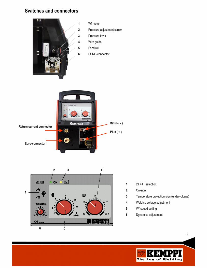
Switches and connectors
1 Wf-motor
2 Pressure adjustment screw
3 Pressure lever
4 Wire guide
5 Feed roll
6 EURO-connector
Plus ( + )
Minus ( - )Return current connector
Euro-connector
1
2 3 4
56
1 2T / 4T selection
2 On-sign
3 Temperature protection sign (undervoltage)
4 Welding voltage adjustment
5 Wf-speed setting
6 Dynamics adjustment
4

Operation principle
KempactTM MIG 2520 and 2530 are compact MIG-inverter power sources designed for repairand installation work and for light or middle-weight industrial use.
KempactTM MIG 2520 and 2530 power sources are based on IGBT-technology and controlledby PWM-principle. Inverter operating frequency is 30 kHz.
All functions and welding properties of KempactTM Pulse-power sources are programmaticallygenerated.
KempactTM Pulse-power source´s power stage operating principle is shown below:
UG1
UG2
UG3
UG4
UT1
UG5
UL1
G1
G3
G2
G4
G5
L1UG1
UG3 UG4
UG2
UT1
UG5 UL1
approx. + 570 V
T1
5
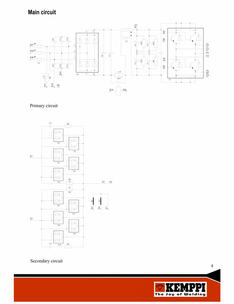
KempactTM MIG-power source´s power stage is a full-bridge and an IGBT-module is used as apower switch.
When IGBT-transistors G1 and G4 conduct, there is positive voltage UT1 in main transformer T1primary and when IGBT-transistors G2 and G3 conduct there is negative voltage UT1 in maintransformer primary. Power is adjusted by changing the IGBT timings (PWM).
Main transformer T1 secondary voltages are rectified with a full-wave rectifier G5 and secondaryvoltage waves are dampened by secondary choke L1.
+ t
L2
X27
X24
X30
+ t
X11
X10 X9
X18
C8
C10
C13
C9
C11
C12
5
6
7
1 2
3 4V2
C6 C7
R13
X19 X20
L1
C4
C3
R12
R11
C2
C1
R10
R9
X2G3
X8G1
X3G4
X6G2
X1E3X7E1X21
X22
X4E4X5E2
V1
X23
R5
Main circuit
Primary circuit
Secondary circuit
U
C2 R6
V1
V2
V3
V4
V5R4
R3
V6
V7
V8
V9
V10C1 R5
X1
X2
X3 X4
R1
R2
X5
X6
X7
U
6
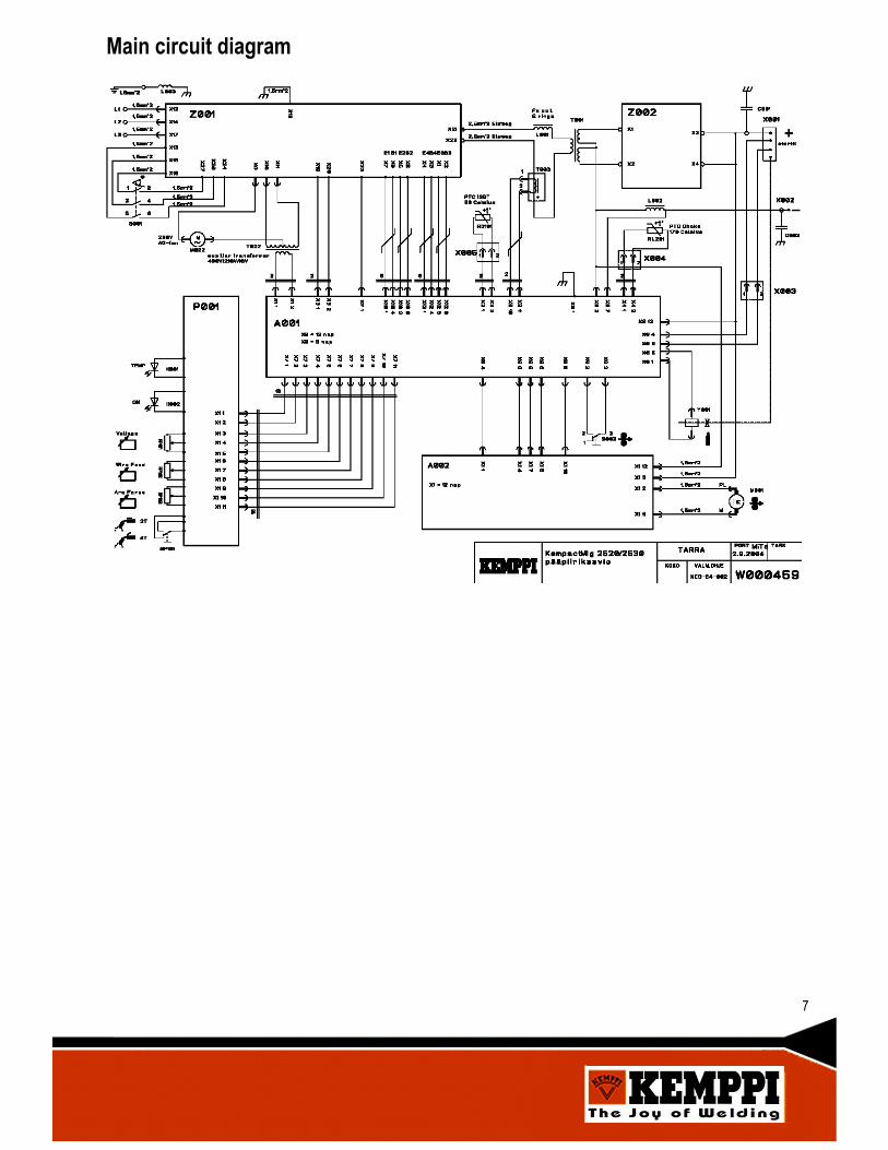
Main circuit diagram
7

General
Troubleshooting diagram
PROBLEM POSSIBLE CAUSE REMEDYThe power source doesn´t start. Net fuses or supply cable. Check the net fuses or supply cable
condition.
Power source overheat shieldyellow signal almp is on just afterstarting the machine up.
Net fuses or supply cable. Check the net fuses and supply cablecondition.
The power source can´t deliverfull power.
Net fuses or supply cable.
Main transformer T001 orsecondary diode card Z002.
Check the net fuses and supply cablecondition.
Check the main transformer T001ferrites and secondary diode carddiodes.
8
The machine may be repaired only by an authorized and licensed technician or workshop!
First do a visual check to find the possible loose connectors, broken wires or signs of overheating
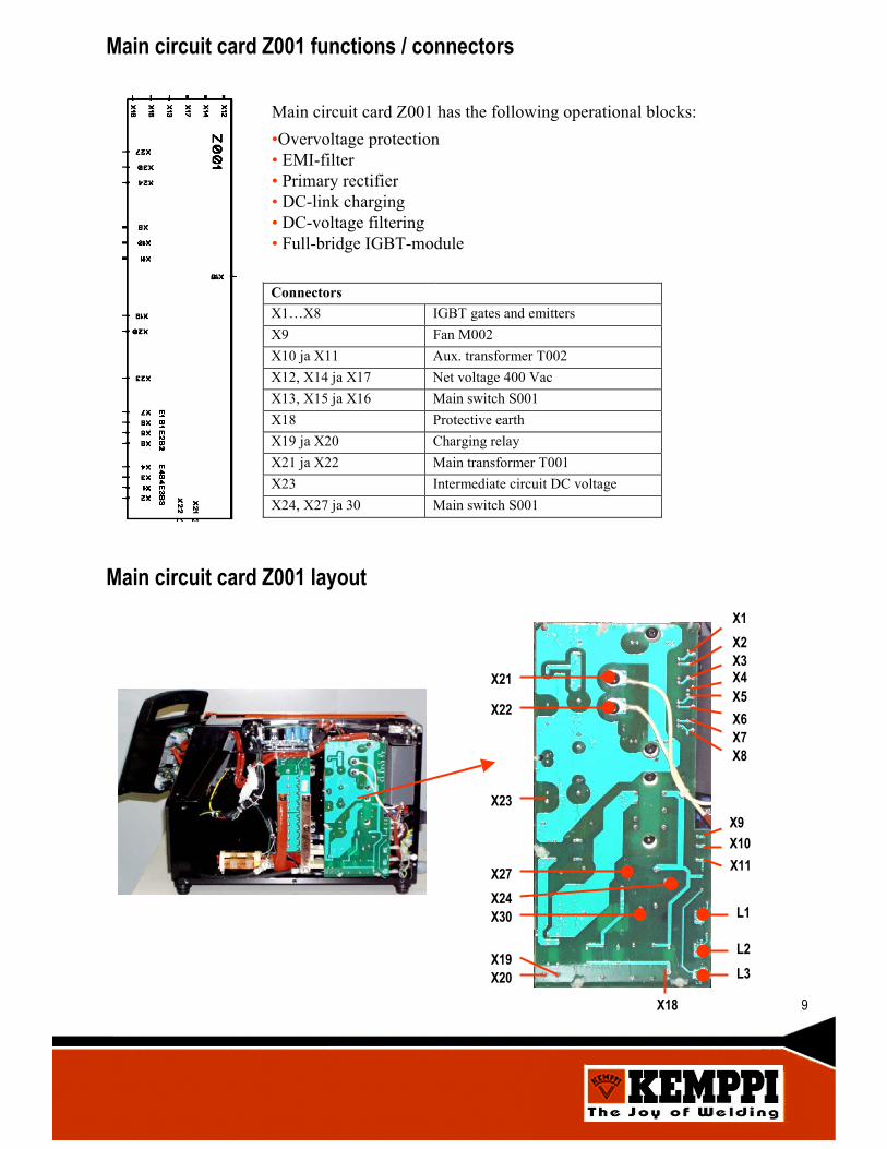
Main circuit card Z001 functions / connectors
Main circuit card Z001 has the following operational blocks:•Overvoltage protection• EMI-filter• Primary rectifier• DC-link charging• DC-voltage filtering• Full-bridge IGBT-module
ConnectorsX1…X8 IGBT gates and emittersX9 Fan M002X10 ja X11 Aux. transformer T002X12, X14 ja X17 Net voltage 400 VacX13, X15 ja X16 Main switch S001X18 Protective earthX19 ja X20 Charging relayX21 ja X22 Main transformer T001X23 Intermediate circuit DC voltageX24, X27 ja 30 Main switch S001
Main circuit card Z001 layoutX1X2X3X4X5X6X7X8
X9X10X11
L1
L2L3
X18
X20X19
X30X24X27
X23
X22
X21
9
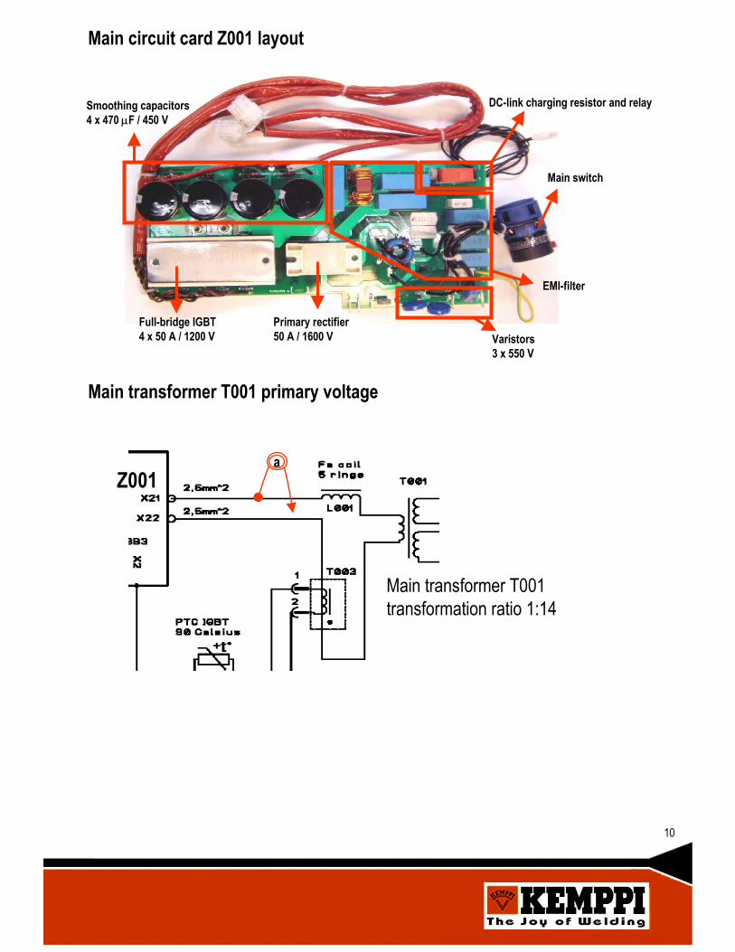
Main circuit card Z001 layout
Smoothing capacitors4 x 470 µF / 450 V
Full-bridge IGBT4 x 50 A / 1200 V
Primary rectifier50 A / 1600 V Varistors
3 x 550 V
DC-link charging resistor and relay
Main switch
EMI-filter
Main transformer T001 primary voltage
Z001a
Main transformer T001 transformation ratio 1:14
10
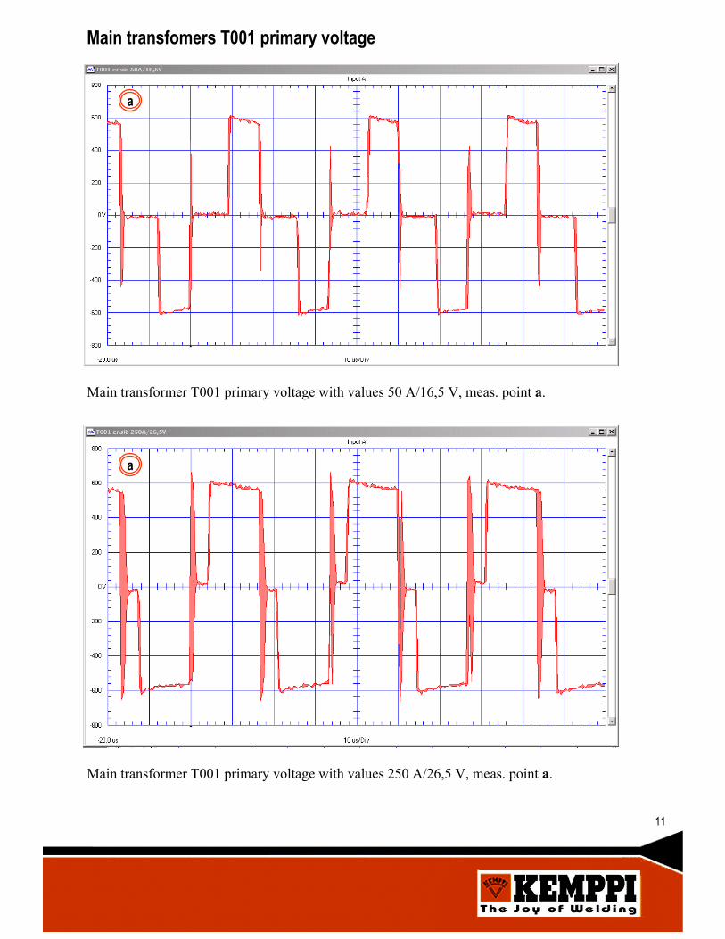
Main transfomers T001 primary voltage
Main transformer T001 primary voltage with values 50 A/16,5 V, meas. point a.
a
Main transformer T001 primary voltage with values 250 A/26,5 V, meas. point a.
a
11
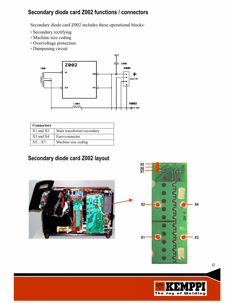
Secondary diode card Z002 functions / connectors
Secondary diode card Z002 includes these operational blocks:• Secondary rectifying• Machine size coding• Overvoltage protection• Dampening circuit
ConnectorsX1 and X2 Main transformer secondaryX3 and X4 Euro-connectorX5…X7 Machine size coding
Secondary diode card Z002 layoutX5X6X7
X2
X1 X3
X4
12
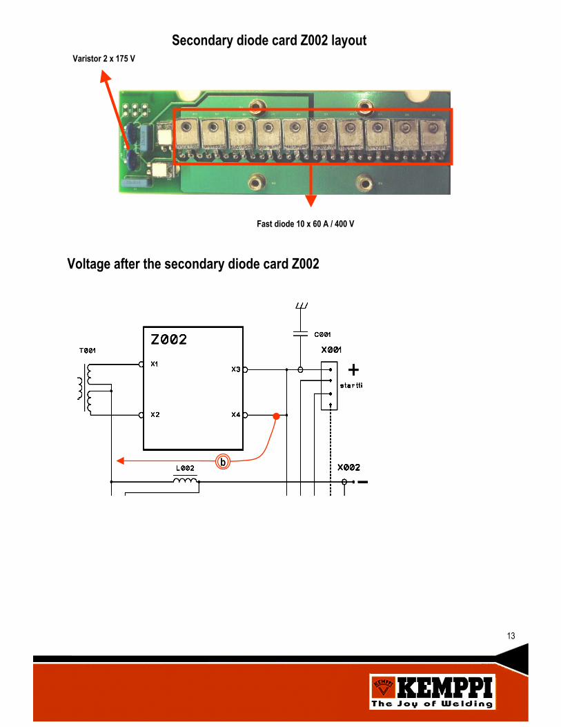
Fast diode 10 x 60 A / 400 V
Varistor 2 x 175 V
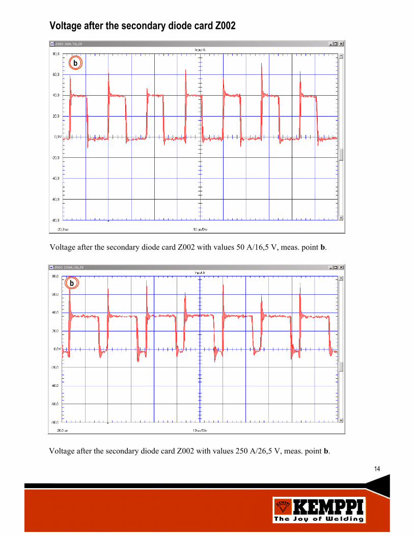
Voltage after the secondary diode card Z002
b
13
Secondary diode card Z002 layout
b
Voltage after the secondary diode card Z002 with values 50 A/16,5 V, meas. point b.
c
Voltage after the secondary diode card Z002 with values 250 A/26,5 V, meas. point b.
b
14
Voltage after the secondary diode card Z002
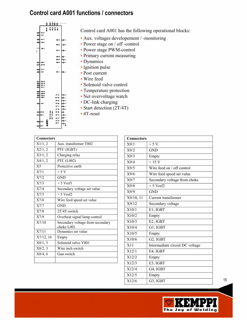
Control card A001 has the following operational blocks: • Aux. voltages developement / -monitoring• Power stage on / off -control• Power stage PWM-control• Primary current measuring • Dynamics• Ignition pulse• Post current• Wire feed• Solenoid valve control• Temperature protection• Net overvoltage watch• DC-link charging• Start detection (2T/4T)• 4T-reset
Control card A001 functions / connectors
ConnectorsX1/1, 2 Aux. transformer T002X2/1, 2 PTC (IGBT)X3/1, 2 Charging relayX4/1, 2 PTC (L002)X5 Protective earthX7/1 + 5 VX7/2 GNDX7/3 + 5 Vref1X7/4 Secondary voltage set valueX7/5 + 5 Vref2X7/6 Wire feed speed set valueX7/7 GNDX7/8 2T/4T-switchX7/9 Overheat signal lamp controlX7/10 Secondary voltage from secondary
choke L001X7/11 Dynamics set valueX7/12, 16 EmptyX8/1, 5 Solenoid valve Y001X8/2, 3 Wire inch switchX8/4, 6 Gun switch
ConnectorsX9/1 + 5 VX9/2 GNDX9/3 EmptyX9/4 + 15 VX9/5 Wire feed on / off controlX9/6 Wire feed speed set valueX9/7 Secondary voltage from chokeX9/8 + 5 Vref2X9/9 GNDX9/10, 11 Current transformerX9/12 Secondary voltageX10/1 E1, IGBTX10/2 EmptyX10/3 E2, IGBTX10/4 G1, IGBTX10/5 EmptyX10/6 G2, IGBTX11 Intermediate circuit DC voltageX12/1 E4, IGBTX12/2 EmptyX12/3 E3, IGBTX12/4 G4, IGBTX12/5 EmptyX12/6 G3, IGBT 15

Control card A001 layout
X9
X11
H6
X12 H4 H3 X10 H5 X5 X4 X3 X2 X1
H2
H1
X7
X8LEDs:H1 + 5VH2 + 15VH3…H6 Gate pulses
Z001
c
IGBT gate pulses
16
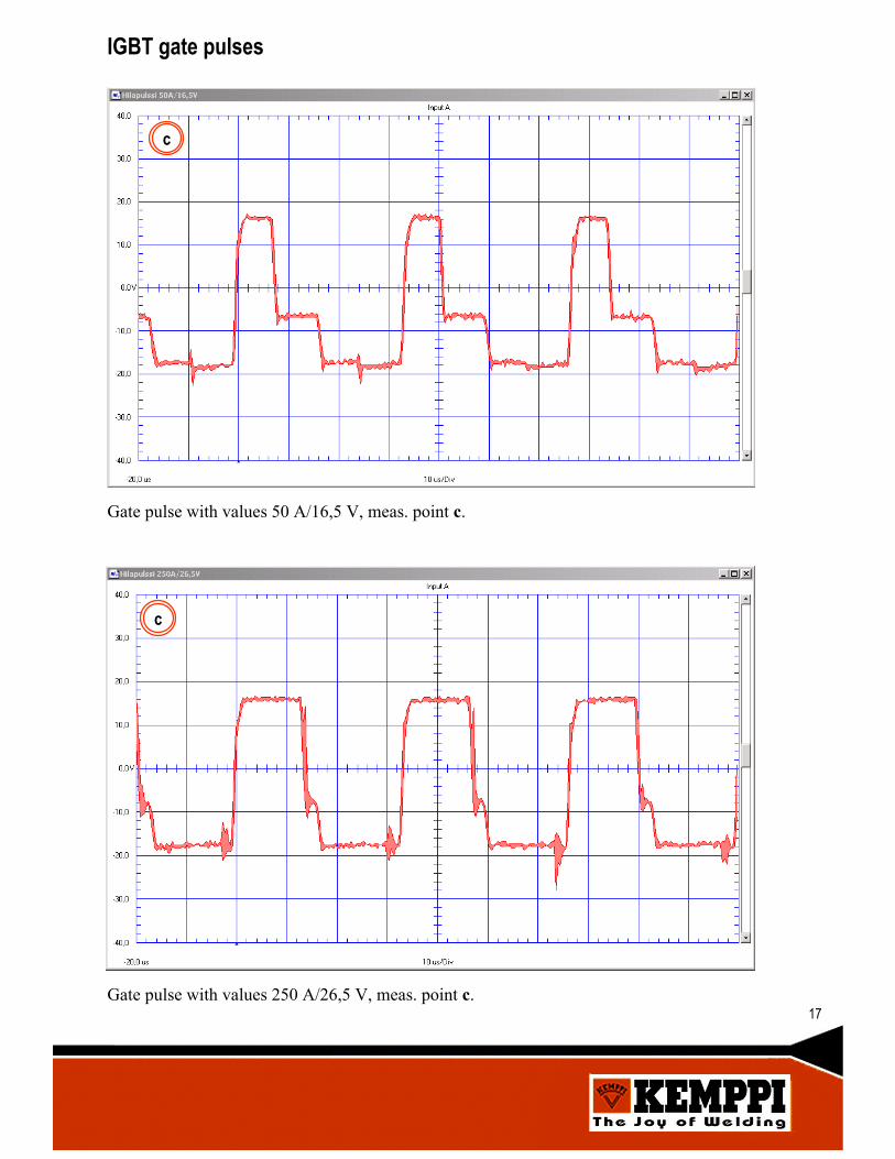
Gate pulse with values 250 A/26,5 V, meas. point c.
c
IGBT gate pulses
Gate pulse with values 50 A/16,5 V, meas. point c.
c
17
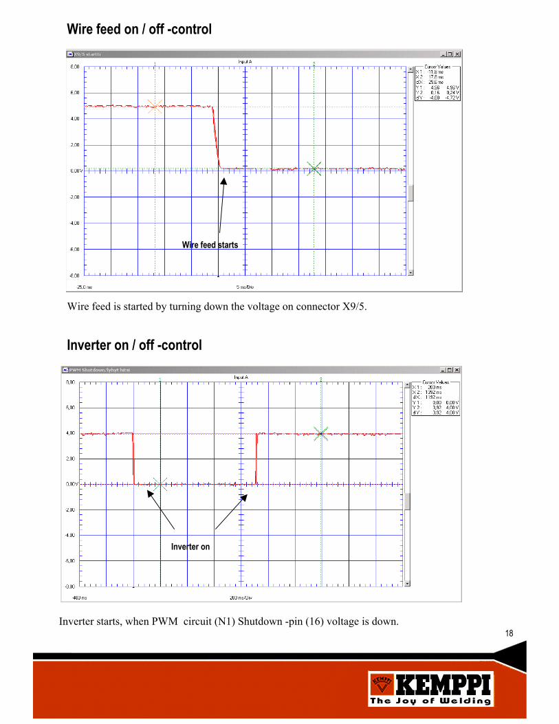
Wire feed starts
Wire feed is started by turning down the voltage on connector X9/5.
Wire feed on / off -control
Inverter on
Inverter starts, when PWM circuit (N1) Shutdown -pin (16) voltage is down.
Inverter on / off -control
18
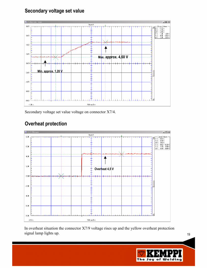
Secondary voltage set value
Secondary voltage set value voltage on connector X7/4.
Min. approx. 1,20 V
Max. approx. 4,60 V
In overheat situation the connector X7/9 voltage rises up and the yellow overheat protectionsignal lamp lights up.
Overheat 4,5 V
Overheat protection
19
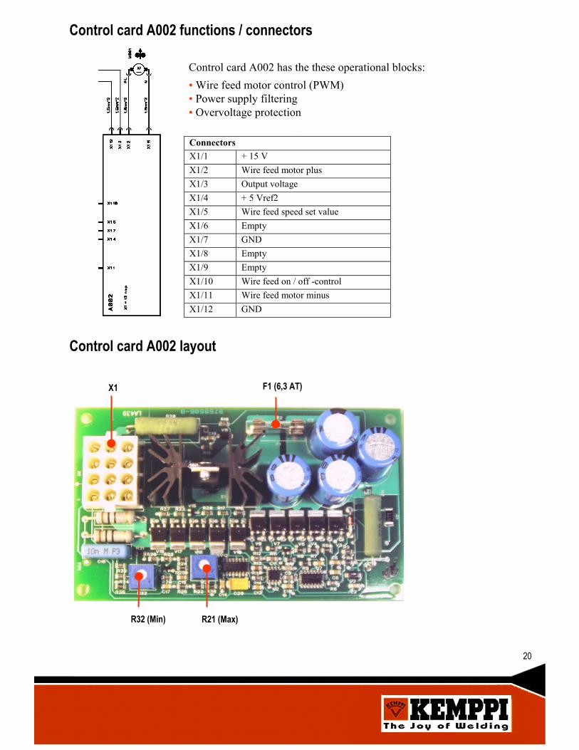
Control card A002 functions / connectors
Control card A002 has the these operational blocks:• Wire feed motor control (PWM)• Power supply filtering• Overvoltage protection
ConnectorsX1/1 + 15 VX1/2 Wire feed motor plusX1/3 Output voltageX1/4 + 5 Vref2X1/5 Wire feed speed set valueX1/6 EmptyX1/7 GNDX1/8 EmptyX1/9 EmptyX1/10 Wire feed on / off -controlX1/11 Wire feed motor minusX1/12 GND
Control card A002 layout
X1
R32 (Min) R21 (Max)
F1 (6,3 AT)
20
Wire feed on / off -control
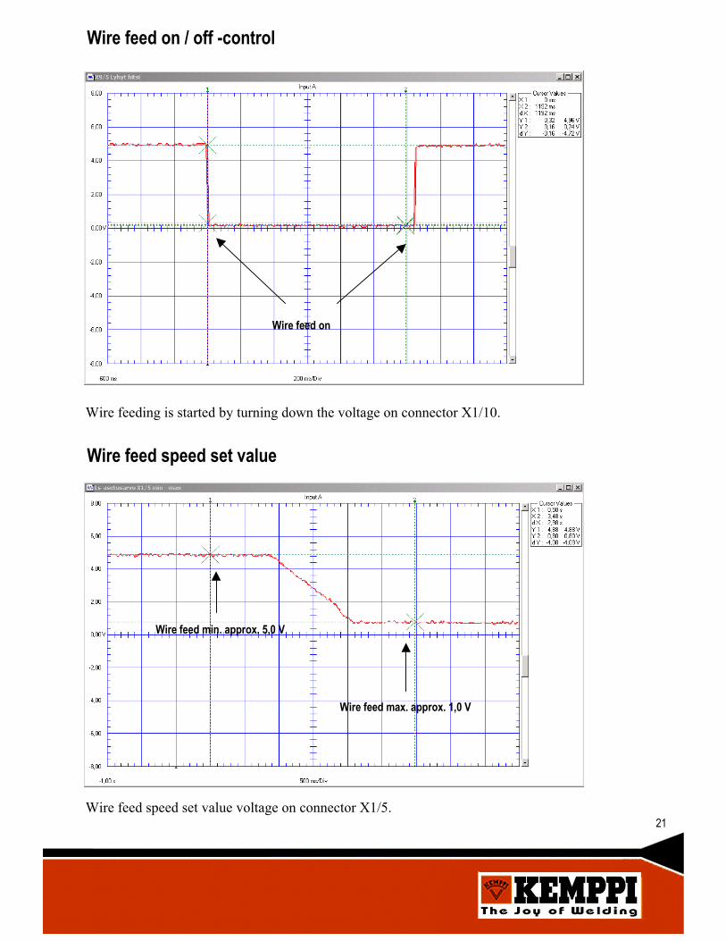
Wire feeding is started by turning down the voltage on connector X1/10.
Wire feed on
Wire feed speed set value voltage on connector X1/5.
Wire feed min. approx. 5,0 V
Wire feed max. approx. 1,0 V
Wire feed speed set value
21

Wire feed motor M001 voltage
a) b) c)
a) Wire feed motor M001 voltage 1 m/min setting, X1/2-X1/11b) Wire feed motor M001 voltage 10 m/min setting, X1/2-X1/11c) Wire feed motor M001 voltage 18 m/min setting, X1/2-X1/11
Wire feed speed minimum and maximum adjustments
After replacing control card A002 or wire feed motor M001 the wire feed speed must bechecked and if necessary, adjusted as follows:1. From panel set the wire feed speed to 18 m/min2. Check the actual wire feed speed and adjust it to 18…18,2 m/min, using trimmer R21.3. From panel set the wire feed speed to 2 m/min4. Check the actual wire feed speed and adjust it to 2…2,2 m/min, using trimmer R32.5. Re-check the speed adjustments and make sure the wire feed speed setting by the panel isoperating properly.
22
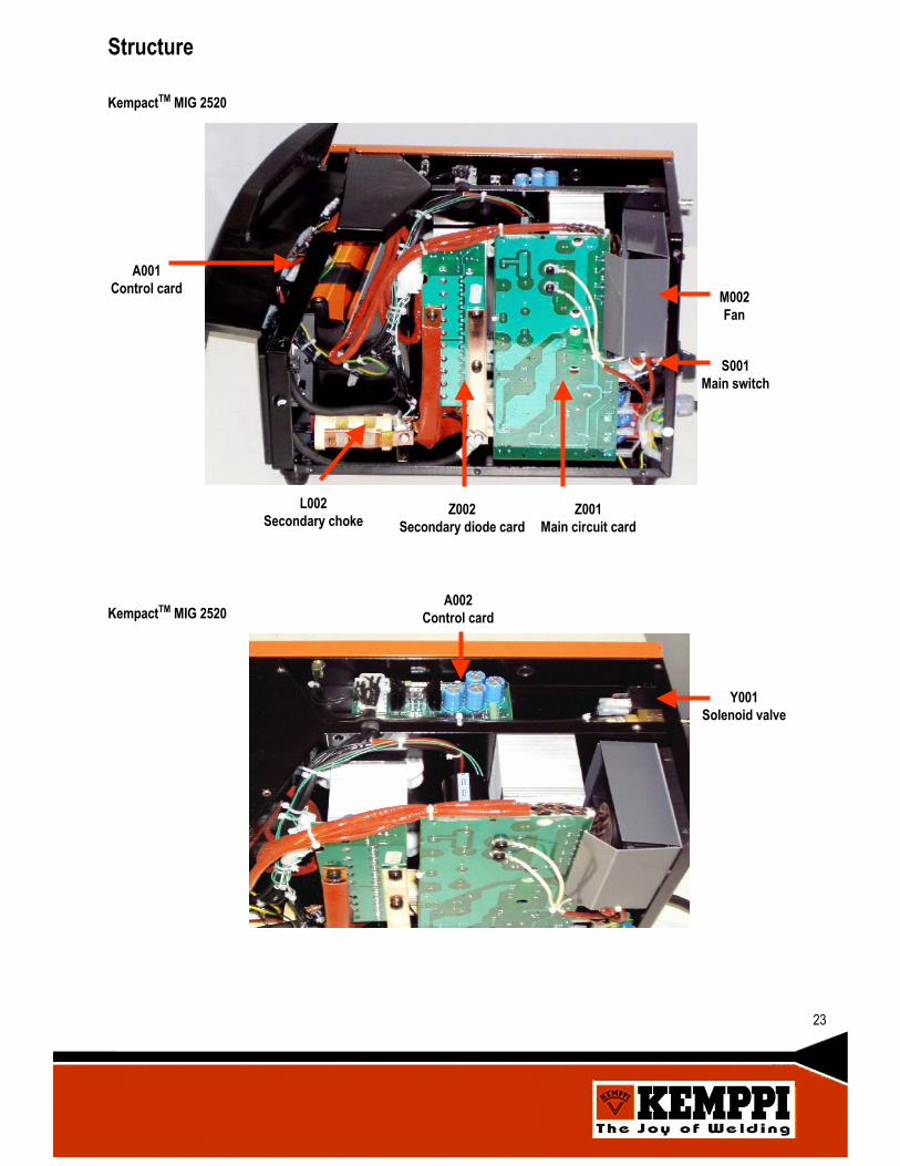
Structure
A001Control card
L002Secondary choke
Z002Secondary diode card
Z001Main circuit card
M002Fan
S001Main switch
A002Control card
Y001Solenoid valve
KempactTM MIG 2520
KempactTM MIG 2520
23
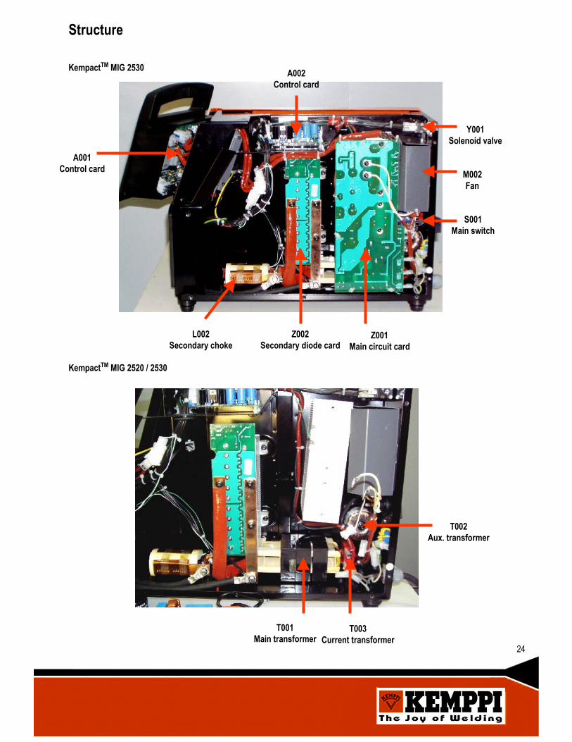
A001Control card
L002Secondary choke
Z002Secondary diode card
Z001Main circuit card
A002Control card
Y001Solenoid valve
M002Fan
S001Main switch
KempactTM MIG 2530
Structure
T001Main transformer
T003Current transformer
T002Aux. transformer
KempactTM MIG 2520 / 2530
24
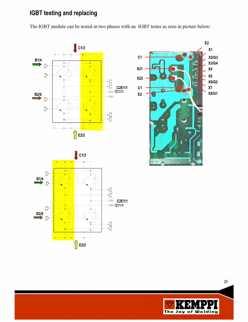
IGBT testing and replacing
25
X2G3
X8G1
X3G4
X6G2
X1E3X7E1
X21
X22
X4E4X5E2
C1/3
C2E1/1
B1/4
X1
X2/G3X3/G4X4X5X6/G2X7X8/G1
X22
X21
C1
C1
E2
E2
B2/6
E2/2
X2G3
X8G1
X3G4
X6G2
X1E3X7E1
X21
X22
X4E4X5E2
C1/3
C2E1/1
B1/4
B2/6
E2/2
The IGBT module can be tested in two phases with an IGBT tester as seen in picture below:

26
IGBT testing and replacing
Mounting the IGBT to the heat sinkThe tools and premises used in this work must be clean, free of dirt and dust. Even very smallparticles (0,050mm) between the surfaces may increase the gap between heatsink and module,causing overheating and possible damage.
Heat transfer compound is to be spread in an even layer of approximately 0,1 mm onto themodule base. Then the module should be immediately mounted on the heat sink, in order tominimize the possibility of dirt getting between the components.
First all the M5 type screws are tightened to 0,5…2 Nm, after which the module can betightened into the nominal torque of 3 Nm. After a pause of some minutes the torques should bere-checked.
It is normal, that after the final tightening there is a slight collar of paste around the modulesides. This tells us, that the amount of paste is adequate.

27
Notes