Embed Size (px)
Citation preview

IMVIOBOX-IA-xx-15 | 111684-00.01 | Version 1.5 ENGLISH / DEUTSCH / ESPAÑOL / FRANÇAIS / 日本語
Installation Manual / Installationsanleitung / Instrucciones de instalación / Instructions d’installation / 設置説明書SMA INVERTER MANAGER / SMA DIGITAL I/O BOX / LCS-TOOL

SMA Solar Technology AG / SMA Solar Technology America LLC
2 IMVIOBOX-IA-xx-15

IMVIOBOX-IA-xx-15 | Version 1.5 ENGLISH
1 Information on this Document1.1 ValidityThis document is valid for the SMA Inverter Manager, the SMA Digital I/O Box, and for the LCS-Tool.
1.2 Target GroupThe activities described in this document must only be performed by qualified persons. Qualified persons must have the following skills:
• Training in the installation and commissioning of electrical devices
• Training in how to deal with the dangers and risks associated with installing and using electrical devices and installations
• Training in the installation and configuration of IT systems
• Knowledge of how an inverter works and is operated• Knowledge of all applicable laws, standards and
directives• Knowledge of and compliance with this document and
all safety information and warning messages
1.3 Symbols
1.4 Nomenclature
Symbol ExplanationIndicates a hazardous situation which, if not avoided, will result in death or serious injuryIndicates a hazardous situation which, if not avoided, can result in death or serious injuryIndicates a hazardous situation which, if not avoided, can result in minor or moderate injuryIndicates a situation which, if not avoided, can result in property damage
Information that is important for a specific topic or goal, but is not safety-relevant
☐ Indicates a requirement for meeting a specific goal
☑ Desired result✖ A problem that might occur
Complete designation Designation in this document
SMA Inverter Manager Inverter ManagerSMA Digital I/O Box I/O BoxLocal commissioning and service tool (LCS-Tool)
LCS-Tool
SMA Solar Technology AG SMASMA Solar Technology America LLCSMA Solar Technology Canada Inc.
Symbol Explanation
Installation ManualSMA INVERTER MANAGER / SMA DIGITAL I/O BOX / LCS-TOOL
2 Safety SMA Solar Technology AG / SMA Solar Technology America LLC
4 IMVIOBOX-IA-xx-15 Installation Manual
2 Safety2.1 Intended UseThe Inverter Manager is a device for monitoring and controlling up to 42 Sunny Tripower 60 and Sunny Highpower Peak1 in decentralized PV system.The I/O Box is a function interface for one Inverter Manager. The I/O Box receives commands for grid management services via digital signals and sends these specifications to the Inverter Manager.The Inverter Manager receives the specifications from theI/O Box and controls all inverters in the PV system accordingly. The Inverter Manager and the I/O Box must only be used indoors and must only be operated with the Sunny Tripower 60 and Sunny Highpower Peak1.The LCS-Tool is required for commissioning and servicing the inverters via the Inverter Manager. The LCS-Tool is the primary user interface for the PV system.Use this product only in accordance with the information provided in the enclosed documentation and with the locally applicable standards and directives. Any other application may cause personal injury or property damage. For safety reasons, it is not permitted to modify the product or install components that are not explicitly recommended or distributed by SMA for the product. Unauthorized changes and modifications will void all warranty claims and the operating permission. Any use of the product other than that described in the Intended Use section does not qualify as appropriate. The type label must remain permanently attached to the product. The enclosed documentation is an integral part of this product.
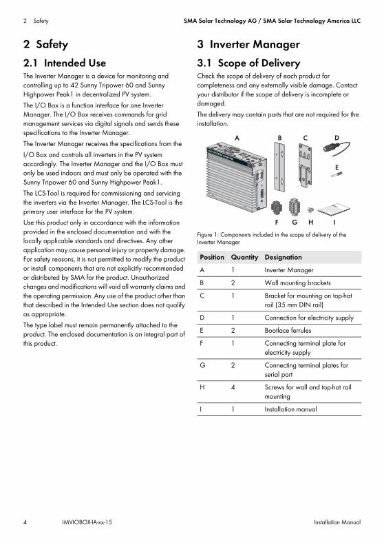
3 Inverter Manager3.1 Scope of DeliveryCheck the scope of delivery of each product for completeness and any externally visible damage. Contact your distributor if the scope of delivery is incomplete or damaged.The delivery may contain parts that are not required for the installation.
Figure 1: Components included in the scope of delivery of the Inverter Manager
Position Quantity DesignationA 1 Inverter ManagerB 2 Wall mounting bracketsC 1 Bracket for mounting on top-hat
rail (35 mm DIN rail)D 1 Connection for electricity supplyE 2 Bootlace ferrulesF 1 Connecting terminal plate for
electricity supplyG 2 Connecting terminal plates for
serial portH 4 Screws for wall and top-hat rail
mountingI 1 Installation manual

SMA Solar Technology AG / SMA Solar Technology America LLC 3 Inverter Manager
Installation Manual IMVIOBOX-IA-xx-15 5
3.2 Mounting the Inverter Manager
3.2.1 Option 1: Wall Mounting
3.2.2 Option 2: Mounting on Top-Hat Rail
Damage to the products and cables due to moistureThe Inverter Manager and the I/O Box are not protected against splash water. Consequently, moisture can penetrate the device and damage the products and cables.
• The Inverter Manager and the I/O Box must be installed in a dry environment, e.g. indoors or in a splash-proof enclosure (degree of protection: at least IP54 (NEMA 3R)).

3 Inverter Manager SMA Solar Technology AG / SMA Solar Technology America LLC
6 IMVIOBOX-IA-xx-15 Installation Manual
3.3 Connection to the Inverter Manager3.3.1 Safety Information
3.3.2 Circuitry Overview
Figure 2: Circuitry overview
Danger to life due to electric shockLethal voltages are present at the connection point of the utility grid.
• Disconnect the connection point from voltage sources and ensure that the connection point is voltage-free.
Position DesignationA InverterB PC with LCS-ToolC Router
D SunSpec Alliance compatible weather station (optional)
E I/O Box (optional)F Inverter Manager
Position Designation

SMA Solar Technology AG / SMA Solar Technology America LLC 3 Inverter Manager
Installation Manual IMVIOBOX-IA-xx-15 7
3.3.3 Connecting the Inverter and Router via EthernetPin assignment of network ports (LAN 1 and LAN 2):
Figure 3: Pin assignment of network ports
3.3.4 Connecting the I/O Box and Weather Station (Optional)
Pin assignment of the serial interface (RS485) at the Inverter Manager:
Figure 4: Pin assignment of the serial interface
The I/O Box must be connected to port 2 of the Inverter Manager. Termination for the RS485 interface is not necessary.
Interfaces and Data of the Weather StationOnly one weather station can be connected to each Inverter Manager. The weather station must be connected to port 1 of the Inverter Manager. A maximum of two temperature sensors are supported.The following data of the weather station are provided by the Inverter Manager:
Pin Assignment for 10/100 Mbps
Assignment for 1000 Mbps
1 ETx+ TRD(0)+2 ETx- TRD(0)-3 ERx+ TRD(1)+4 --- TRD(2)+5 --- TRD(2)-6 ERx- TRD(1)-7 --- TRD(3)+8 --- TRD(3)-
Do not connect during operationDo not connect the I/O Box or the weather station to the Inverter Manager during operation. Errors might occur that cannot be detected immediately.
• Disconnect the Inverter Manager from voltage sources.
8 1
81
321 4 5
9876
Pin Assignment1 ---2 ---3 DataB(+)4 DataA(-)5 GND6 ---7 ---8 ---
Meteorological data
SunSpec Modbus TCP
LCS-Tool / FTP Push
Sunny Portal
Ambient temperature and PV temperature
yes yes yes
Wind direction and wind speed
yes yes yes
Horizontal irradiation
yes yes If inclined irradiation is not available
Inclined irradiation
no yes yes

3 Inverter Manager SMA Solar Technology AG / SMA Solar Technology America LLC
8 IMVIOBOX-IA-xx-15 Installation Manual
3.3.5 Connecting the Inverter Manager to the Voltage Supply
Procedure:To connect the Inverter Manager to the voltage supply, perform the following actions in the specified order.
• Connect the grounding conductor to the Inverter Manager.
• Connect the power supply unit.
Connecting the Grounding Conductor to the Inverter ManagerShielded ground: The shielded ground (also called "protected ground") is located at the pin connector for the electrical connection in the displayed view.Procedure:
• Ground the Inverter Manager. For this purpose, connect the grounding conductor to the grounding screw of the Inverter Manager. Proper grounding and the correct cable route help limit possible interference emissions due to electromagnetic interferences (EMI).
Connecting the Power Supply Unit
SMA recommends using the top-hat rail power supply available as an accessory (order number: CLCON-PWRSUPPLY)* .
Procedure:1. Mount the power supply unit (see the manufacturer
manual).2. Connect the connection cable to the power supply unit
(see the manufacturer manual). Trim the unused insulated conductors up to the cable sheath and write down the conductor colors.
3. Connect the connection cable to the connecting terminal plate for the voltage supply (9 VDC to 36 VDC). Make sure that the shielded grounding conductor is connected with the grounding terminal.
4. Plug the connecting terminal plate for the voltage supply with connected power supply unit in the pin connector "Power Input" of the Inverter Manager.
5. Connect the AC connection cable to the power supply unit (see the manufacturer manual).
7. Connect the other end of the AC connection cable to the voltage supply.
8. Connect the connection point to the utility grid.☑ Once the Power LED is glowing green, the
Inverter Manager is ready for operation.
3.4 Ethernet Connection of the Inverter ManagerLAN 1 (system network)The IP address and the subnet mask are assigned to the LAN 1 port of the Inverter Manager by an external DHCP server. An IP address can be manually assigned to LAN 1 Port of the Inverter Manager.
LAN 2 (inverter network)The IP address is assigned to the inverter by the Inverter Manager.
Resetting the Inverter Manager to DHCP• Press the power button three times in succession within
one second to reset the Inverter Manager to DHCP.
Danger to life due to electric shock from touching an ungrounded productTouching an ungrounded product can cause a lethal electric shock.
• Ensure that the product is integrated into the existing overvoltage protection.
• Ground the enclosure of the product.
* Not available in all countries.
GND9 to 36 VDC
6.Danger to life due to electric shockLethal voltages are present at the connection point of the utility grid.
• Disconnect the connection point from voltage sources and make sure it cannot be reconnected.

SMA Solar Technology AG / SMA Solar Technology America LLC 3 Inverter Manager
Installation Manual IMVIOBOX-IA-xx-15 9
3.5 LED Signals of the Inverter Manager
3.6 Technical Data
LED State ExplanationPower Glowing
greenThe Inverter Manager is in operation.
Off The Inverter Manager is not in operation.
LAN Glowing green
100 Mbps Ethernet mode
Glowing yellow
1000 Mbps (gigabyte) Ethernet mode
Off No activity or 10 Mbps Ethernet
Tx1, Tx2 (P1-P2)
Flashing green
Data transmission via serial ports P1-P2
Off No data transmission via serial ports P1-P2
Rx1, Rx2 (P1-P2)
Flashing green
Data reception via serial ports P1-P2
Off No data reception via serial ports P1-P2
Voltage supplyInput voltage 9 Vdc to 36 VdcPower consumption < 20 WMaximum conductor cross-section
1.3 mm² (16 AWG)
General dataDimensions (width x height x depth)
160 mm x 125 mm x 49 mm
(6.3 in x 4.9 in x 1.9 in)Weight 940 g (2 lbs)Mounting type Wall mounting or top-hat
railOperating temperature range
-40°C to +75°C-40°F to +167°F
Relative humidity, non-condensing
5% to 95%
Approvals UL 508, UL 60950-1, CSA C22.2 No. 60950-1-07,
EN 60950-1, CCC (GB9254, GB17625.1),
EN 55022, Class A, EN 61000-3-2, Class D,
EN 61000-3-3, EN 55024, FCC Part 15,
Subpart B, Class A
InterfacesUser interface LCS-Tool for PC via EthernetInterface to inverter LAN 2, Ethernet interface
(RJ45)Interface to external network
LAN 1, Ethernet interface (RJ45)
Interface to I/O box (optional)
RS485 (D-sub 9) / SunSpec mode
Sensor interface for SunSpec compatible weather stations (optional)
RS485 (D-sub 9) / SunSpec mode
Maximum cable length for Ethernet connection
100 m (328 ft)
Maximum cable length for RS485 cabling
1200 m (4000 ft)
PV system monitoring Sunny Portal, SunSpec Modbus TCP
Active/reactive power setpoint
Constant value, curve or remotely controlled via
SunSpec Modbus TCP with I/O Box
Supported baud rate for operation of a weather station
9600, 19200, 57600, 115200
Power supply unit (recommended)Type designation CLCON-PWRSUPPLY*
* Not available in all countries.
Input 100 Vac to 240 VacOutput 24 Vdc; 2.5 AAmbient temperature -25°C to +70°CApprovals CE, UL
General data
4 I/O Box SMA Solar Technology AG / SMA Solar Technology America LLC
10 IMVIOBOX-IA-xx-15 Installation Manual
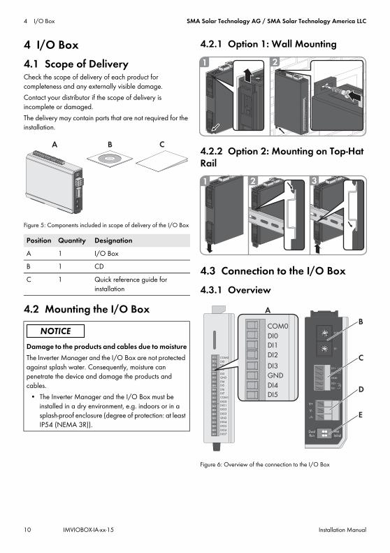
4 I/O Box4.1 Scope of DeliveryCheck the scope of delivery of each product for completeness and any externally visible damage.Contact your distributor if the scope of delivery is incomplete or damaged.The delivery may contain parts that are not required for the installation.
Figure 5: Components included in scope of delivery of the I/O Box
4.2 Mounting the I/O Box
4.2.1 Option 1: Wall Mounting
4.2.2 Option 2: Mounting on Top-Hat Rail
4.3 Connection to the I/O Box4.3.1 Overview
Figure 6: Overview of the connection to the I/O Box
Position Quantity DesignationA 1 I/O BoxB 1 CDC 1 Quick reference guide for
installation
Damage to the products and cables due to moistureThe Inverter Manager and the I/O Box are not protected against splash water. Consequently, moisture can penetrate the device and damage the products and cables.
• The Inverter Manager and the I/O Box must be installed in a dry environment, e.g. indoors or in a splash-proof enclosure (degree of protection: at least IP54 (NEMA 3R)).
A B C
1 2
1 2 3
12
3456
7
8 9 01
2
3456
7
8 9 01
2
3456
7
8 9 01
2
3456
7
8 9 0
D1+
D1-
GND
D2+
D2-
P1
P2
V+
V-
X10
X1
DualRun
RepInitial
COM0
DI0
DI1
DI2
DI3
DI4
DI5
DI6
DI7
COM1
DIO0
DIO1
DIO2
DIO3
GND
DIO4
DIO5
DIO6
DIO7
GND
A
C
D
COM0
DI0
DI1
DI2
DI3
DI4
DI5
GND
B
E

SMA Solar Technology AG / SMA Solar Technology America LLC 4 I/O Box
Installation Manual IMVIOBOX-IA-xx-15 11
4.3.2 Connecting the Inverter Manager
Pin assignment of the RS485 terminal (see Section 3.3.4, page 7):
4.3.3 Connecting the Signal SourceConnection of a Signal Source with Potential-Free Relay Contact
Connection of a Signal Source (10 V to 30 V) with Digital Output Signals
4.3.4 Connecting the I/O Box to the Voltage SupplyConnect the 12 Vdc to 36 Vdc connection line with the terminal for the voltage supply. Connect the grounding of the connection line to the "V" terminal and connect the grounding pin (GND) if grounding is present.
Position DesignationA Digital inputs for connecting a signal source
(inputs DI0 to DI5 can be assigned; all other inputs have no function)
B Maintain the default setting: X1 = 1, X10 = 0
C Connection of the Inverter ManagerD Connection of the electricity supplyE Maintain the default setting: 1 = Dual,
2 = Initial
Do not connect during operationDo not connect the I/O Box to the Inverter Manager during operation. Errors might occur that cannot be detected immediately.
• Disconnect the Inverter Manager from voltage sources.
• Connect the I/O Box with the Inverter Manager.• Reconnect the Inverter Manager to the voltage
supply.
Pin AssignmentD2- ---D2+ ---GND GNDD1- DataA(-)D1+ DataB(+)
(5) GND
(3) Data B (+)D1+(4) Data A (−)/D1−
Pin AssignmentV- / V+ Voltage supply 24 Vdc
(12 Vdc to 36 Vdc)
Diameter of the leadsFor safety reasons, the leads for the electricity supply must have a diameter of at least 2 mm².
COM0
DI0
DI1
DI2
DI3
DI4
DI5
DI6
DI7
COM1
DIO0
DIO1
DIO2
DIO3
GND
DIO4
DIO5
DIO6
DIO7
GND
COM0
DI0
DI1
DI2
DI3
DI4
DI5
GND
Dry Contact:closed: DI0 = onopen: DI0 = off
COM0
DI0
DI1
DI2
DI3
DI4
DI5
DI6
DI7
COM1
DIO0
DIO1
DIO2
DIO3
GND
DIO4
DIO5
DIO6
DIO7
GND
COM0
DI0
DI1
DI2
DI3
DI4
DI5
GND
Wet Contact:0 V to 3 V = off
10 V to 30 V = on
UU10 V to 30 V

4 I/O Box SMA Solar Technology AG / SMA Solar Technology America LLC
12 IMVIOBOX-IA-xx-15 Installation Manual
4.3.5 LED Signals of the I/O Box
4.4 Technical Data
LED State ExplanationPower Glowing
yellowThe I/O Box is in operation.
Off The I/O Box is not in operation.Ready Glowing
greenThe system is ready for operation.
Green is flashing once per second
The "detect" function was triggered.
Flashing green every 0.5 seconds
Firmware is being updated.
Flashing green
When the green LED is on for five seconds and then goes off for five seconds, it means that the system is in "Safe Mode".
Off The system is not ready for operation.
Port 1 Flashing green
Data is being sent or received.
Port 2 Flashing yellow
Data is being sent or received.
System dataPower Source 24 Vdc nominal,
12 Vdc to 36 VdcCabling I/O cable max. 25 mm²
(4 AWG)Dimensions 27.8 mm x 124 mm x 84 mm
(1.09 in x 4.88 in x 3.31 in)Weight < 200 gOperating temperature range
Standard module:-10°C to +75°C14°F to 167°F
Storage temperature -40°C to +85°C-40°F to 185°F
Relative humidity, non-condensing
5% to 95%
Operating altitude < 2000 m
Industry standards and certifications
UL 508, CE, FCC Class A
Digital input Sensor type Potential-free contact
(NPN or PNP); wet contactI/O mode DI or event counterPotential-free contact On = ground fault
Off = openWet contact (DI to COM) On = 10 Vdc to 30 Vdc
Off = 0 Vdc to 3 VdcInsulation voltage 3000 Vdc or 2000 VeffCounter/Frequency 250 Hz, memory in off-state
System data

SMA Solar Technology AG / SMA Solar Technology America LLC 5 LCS-Tool
Installation Manual IMVIOBOX-IA-xx-15 13
5 LCS-ToolThe inverters and the Inverter Manager must be commissioned via the local commissioning and service tool (LCS-Tool). Commissioning is required before the inverters are connected to the utility grid and start to feed-in power. It is recommended to use the latest version of the LCS-Tool. The LCS-Tool is available in the download area at www.SMA-Solar.com.The hardware requirements for the LCS-Tool are:
• PC with WindowsTM 7 and later• 1 GB HDD• 2 GB RAM
The LCS-Tool must be installed on a local PC drive. The PC must be connected to the LAN 1 port of the Inverter Manager via a router (DHCP recommended).
Figure 7: Commissioning inverters via the LCS-Tool 5.1 Commissioning1. Start up the LCS-Tool. The tool shows a list of all
identified Inverter Managers. It can take several minutes until the LCS-Tool has identified all Inverter Managers.
2. The screen now shows a list of all Inverter Managers (see figure 8). To start the assistant, click on the Inverter Manager to be configured. By clicking on the Inverter Manager, the inverters found by the Inverter Manager are displayed. Inverters that have not been commissioned (no grid code assigned) are presented with a blue square together with their software version.
INFORMATIONThe LAN 1 port of the Inverter Manager must have an IP address assigned by a DHCP server that is connected to the LAN 1 port.An IP address can be manually assigned to the Inverter Manager.It is important that the computer (on which the LCS-Tool runs) is connected to the same IP subnet as the Inverter Manager. The Inverter Manager may not be assigned an IP from the system network range 192.168.4.0/24.The LAN 2 port is only intended for inverters.
A LCS-ToolB Router (DHCP recommended)C Inverter ManagerD InverterE LAN 1F LAN 2

5 LCS-Tool SMA Solar Technology AG / SMA Solar Technology America LLC
14 IMVIOBOX-IA-xx-15 Installation Manual
Figure 8: LCS-Tool - start screen
3. Assign a password for your user group when first registering. The security status of your password is displayed.
4. Verify that date and time are correct. If not, set date and time and continue (see figure 9).
Figure 9: LCS-Tool - checking date and time

SMA Solar Technology AG / SMA Solar Technology America LLC 5 LCS-Tool
Installation Manual IMVIOBOX-IA-xx-15 15
5. Optionally, you can assign a name, location and owner of the Inverter Manager (see figure 10).
Figure 10: LCS-Tool - PV system details
6. A list of the identified inverters of the selected Inverter Manager is displayed (see figure 11).
Make sure that all inverters are present. It is possible to continue the configuration of the listed inverters even if not all inverters are detected. The undetected inverters can always be configured later.

5 LCS-Tool SMA Solar Technology AG / SMA Solar Technology America LLC
16 IMVIOBOX-IA-xx-15 Installation Manual
Figure 11: LCS-Tool - list of the connected inverters
7. Select the desired country from the list of options available for the inverters in the network (see figure 12).
8. Select the desired grid code from the list of options available for the selected country. If necessary, load a customer specific grid code by clicking the button [Load] (see figure 12). The button [Create] is inactive and cannot be used.
Figure 12: LCS-Tool - selecting the country and grid code

SMA Solar Technology AG / SMA Solar Technology America LLC 5 LCS-Tool
Installation Manual IMVIOBOX-IA-xx-15 17
9. The LCS-Tool prompts for a confirmation of the selected country and grid code (see figure 13). A wrong configuration can be changed by clicking the [Back] button and by changing the settings in the previous window.
Figure 13: LCS-Tool - checking the country and grid code
10. The system then applies the grid code selected on the Inverter Manager to the detected inverters. Any inverter added at a later stage automatically inherits the same grid code. The application of only one grid code is possible per Inverter Manager.
11. A green square identifies the commissioned inverters. The inverters are only connected to the utility grid when the [Start] command has been carried out from the bar below the start menu (see figure 14).
INFORMATIONIt is essential to choose the correct grid code. A modification after the first ten operating hours have passed is only possible with a personal SMA Grid Guard code.The grid code parameters can be changed subsequently with the LCS-Tool (see section 5.2.6, page 26). Prerequisite is the use of the latest version of the LCS-Tool.

5 LCS-Tool SMA Solar Technology AG / SMA Solar Technology America LLC
18 IMVIOBOX-IA-xx-15 Installation Manual
Figure 14: LCS-Tool - list of all inverters connected to the Inverter Manager
12. If sufficient PV power is present and the grid code conditions are met, the inverter starts the operation.
13. During commissioning it is possible to download a commissioning report in the Reports menu. The report contains information about inverter settings, including actual disconnection values for each inverter. By clicking the folder icon in the menu Reports, it is possible to open a folder for commissioning reports (incl. grid code information) (see figure 15).
Figure 15: LCS-Tool - commissioning report
SMA Solar Technology AG / SMA Solar Technology America LLC 5 LCS-Tool
Installation Manual IMVIOBOX-IA-xx-15 19
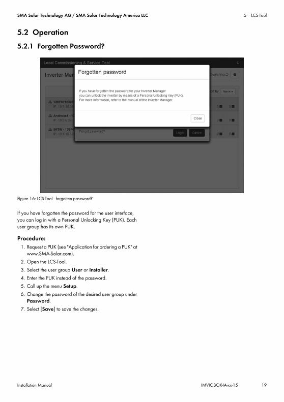
5.2 Operation5.2.1 Forgotten Password?
Figure 16: LCS-Tool - forgotten password?
If you have forgotten the password for the user interface, you can log in with a Personal Unlocking Key (PUK). Each user group has its own PUK.
Procedure:1. Request a PUK (see "Application for ordering a PUK" at
www.SMA-Solar.com).2. Open the LCS-Tool.3. Select the user group User or Installer.4. Enter the PUK instead of the password.5. Call up the menu Setup.6. Change the password of the desired user group under
Password.7. Select [Save] to save the changes.

5 LCS-Tool SMA Solar Technology AG / SMA Solar Technology America LLC
20 IMVIOBOX-IA-xx-15 Installation Manual
5.2.2 Changing the Grid Code
Figure 17: LCS-Tool - entering the SMA Grid Guard code
To reset the Inverter Manager after the first ten operating hours and to select a new country data set, use your SMA Grid Guard code under the user group Installer (see certificate "Order form for the SMA Grid Guard code" at www.SMA-Solar.com).
Procedure:1. Open the LCS-Tool.2. Log in as an Installer.3. Call up the menu Service.4. Enter your SMA Grid Guard code in the field
Individual access code under Grid Guard.5. Select [Save] to save the changes.
☑ A new menu item General is available under the menu Setup.

SMA Solar Technology AG / SMA Solar Technology America LLC 5 LCS-Tool
Installation Manual IMVIOBOX-IA-xx-15 21
5.2.3 Updating the Firmware
Figure 18: LCS-Tool - manual firmware update
You can carry out the firmware update of the Inverter Manager manually. It is recommended to use the latest version of the LCS-Tool. The LCS-Tool is available in the download area at www.SMA-Solar.com.
Procedure:1. Open the LCS-Tool.2. Log in as User or Installer.3. Call up the menu Service.4. Select the tab Inverter Manager under Software
Update.5. Select [Start update] to carry out the update.
☑ The update is carried out now.
Damage to the products due to disruption of the update procedureIf the connection between the Inverter Manager and the computer is disrupted, a damage to the device may occur.
• Do not disconnect the connection between the Inverter Manager and the computer.
• Do not disconnect the computer and Inverter Manager from the electricity supply.
• Do not switch the computer to energy-saving mode.

5 LCS-Tool SMA Solar Technology AG / SMA Solar Technology America LLC
22 IMVIOBOX-IA-xx-15 Installation Manual
5.2.4 Setting the System Fallback
Figure 19: LCS-Tool - setting the fallback parameter
A system fallback can be configured in the event of a communication failure between the Inverter Manager and a superior control unit (e.g. SCADA system or Power Plant Controller). The superordinate system fallback can only be configured via the LCS-Tool. To set the values for a superordinate fallback, use your SMA Grid Guard code under the user group Installer (see section 5.2.2, page 20).
Procedure:1. Open the LCS-Tool.2. Log in as an Installer.3. Call up the menu Setup.4. Enter the respective values under Plant fallback.5. Select [Save] to save the changes.

SMA Solar Technology AG / SMA Solar Technology America LLC 5 LCS-Tool
Installation Manual IMVIOBOX-IA-xx-15 23
5.2.5 Setting Limited Export
Figure 20: LCS-Tool - setting Limited Export
With the Limited Export feature in connection with a Modbus-capable energy meter, a maximum defined AC output power can be made available at the grid-connection point (see figure 22). The total nominal power of all inverters connected to the Inverter Manager is taken into account. The inverter is increased or decreased by the amount of self-consumption to the maximum output power at the grid-connection point. The limitation at the grid-connection point is complied with, while all connected loads can still be supplied with energy from the inverters.The maximum setpoint of the nominal PV system power can be assigned with static or dynamic attributes:
• Assignment of static attributes: Set the parameter Active Power (P_ref) for the active power limitation in menu Inverter Parameter under Protection settings > Support settings > Immediate controls (see Section 5.2.6 “Changing of Inverter Parameters”, page 26).
• Assignment of dynamic attributes: In addition, the setpoint of the nominal PV system power can be limited dynamically via I/O Box, Modbus and direct marketer interface. If the value is set dynamically, the parameter Active Power (P_ref) is overwritten in the LCS-Tool.
This applies to both the regular feed-in operation and to the activated Limited Export function. A load-dependent control is not possible without an activated Limited Export function. The inverters are then directly limited to the setpoint (see figure 23).
Procedure:1. Open the LCS-Tool.2. Log in as an Installer.3. Call up the menu Setup.4. Enter the respective values under Limited Export.5. Select [Save] to save the changes.
The parameters Meter IP-Address, Meter Modbus Port, Meter Modbus Unit ID and the Meter Power Modbus Register are used for the configuration of the energy meter. With zero export as a special case of Limited Export, the feed-in operation into the utility grid can be completely prevented. The parameter Safety Offset indicated as percentage of nominal PV system power is a safety margin to the maximum value of the output power set at the grid-connection point. This safety value is preset for safety reasons and due to sudden load changes. Thus, a safety margin to the setpoint is ensured. With the activation process, the setpoint is reduced to the safety value. Thus, the feed-in power is always less than the actual setpoint.

5 LCS-Tool SMA Solar Technology AG / SMA Solar Technology America LLC
24 IMVIOBOX-IA-xx-15 Installation Manual
The parameter Meter Connection Timeout is the time in seconds that is required to adjust the nominal PV system power to 0 W when communication to the energy meter is interrupted.To acquire an overview of the current system values, open the menu Status and select Overview (see figure 21).
Figure 21: LCS-Tool - Overview of current system values
Modbus controlTo make this limitation permanent, set the desired value in the Modbus register 40349.To disconnect the inverter immediately from the utility grid while the Limited Export function is running, set the value "0" in the Modbus register 40348.For further information on the Modbus interface see technical information "SUNNY TRIPOWER 60 / SUNNY HIGHPOWER PWAEK1 - SunSpec® Modbus® Interface" at www.SMA-Solar.com.

SMA Solar Technology AG / SMA Solar Technology America LLC 5 LCS-Tool
Installation Manual IMVIOBOX-IA-xx-15 25
Figure 22: Feeding-in operation with Limited Export
Figure 23: Feeding-in operation without Limited Export
A InverterB Inverter ManagerC LoadsD Utility gridE Grid-connection pointF Modbus TCPG AC

5 LCS-Tool SMA Solar Technology AG / SMA Solar Technology America LLC
26 IMVIOBOX-IA-xx-15 Installation Manual
5.2.6 Changing of Inverter Parameters
Figure 24: LCS-Tool - changing of inverter parameters
All inverter parameter are Grid Guard protected and require the Grid Guard code for changes. To change the inverter settings, use your SMA Grid Guard code under the user group Installer (see section 5.2.2, page 20).
Procedure:1. Open the LCS-Tool.2. Log in as an Installer.3. Call up the menu Setup.4. Enter the respective values under Inverter
Parameter.5. Select [Save] to save the changes.
Deactivating/Activating the inverter parametersTo activate and deactivate a parameter, double-click on the parameter using the left mouse button. When the parameters are activated, the input fields and buttons are enabled. Inactive parameters are marked with disable.

SMA Solar Technology AG / SMA Solar Technology America LLC 5 LCS-Tool
Installation Manual IMVIOBOX-IA-xx-15 27
Figure 25: LCS-Tool - deactivating/activating the inverter parameters
Changing signs on power factor parametersTo change signs on power factor parameters, click on the sign using the left mouse button.
Figure 26: LCS-Tool - changing signs
5 LCS-Tool SMA Solar Technology AG / SMA Solar Technology America LLC
28 IMVIOBOX-IA-xx-15 Installation Manual
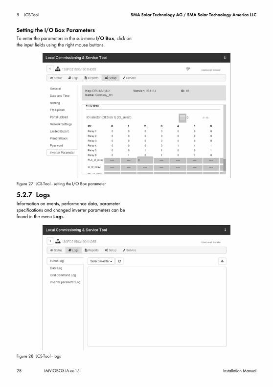
Setting the I/O Box ParametersTo enter the parameters in the sub-menu I/O Box, click on the input fields using the right mouse buttons.
Figure 27: LCS-Tool - setting the I/O Box parameter
5.2.7 LogsInformation on events, performance data, parameter specifications and changed inverter parameters can be found in the menu Logs.
Figure 28: LCS-Tool - logs

IMVIOBOX-IA-xx-15 | Version 1.5 DEUTSCH
1 Hinweise zu diesem Dokument1.1 GültigkeitsbereichDieses Dokument gilt für den SMA Inverter Manager, die SMA Digital I/O Box und das LCS-Tool.
1.2 ZielgruppeDie in diesem Dokument beschriebenen Tätigkeiten dürfen nur Fachkräfte durchführen. Die Fachkräfte müssen über folgende Qualifikation verfügen:
• Ausbildung für die Installation und Inbetriebnahme von elektrischen Geräten
• Schulung im Umgang mit Gefahren und Risiken bei der Installation und Bedienung elektrischer Geräte und Anlagen
• Ausbildung für die Installation und Konfiguration von IT-Systemen
• Kenntnis über Funktionsweise und Betrieb eines Wechselrichters
• Kenntnis der einschlägigen Gesetze, Normen und Richtlinien
• Kenntnis und Beachtung dieses Dokuments mit allen Sicherheits- und Warnhinweisen
1.3 Symbole
1.4 Nomenklatur
Symbol ErklärungWarnhinweis, dessen Nichtbeachtung unmittelbar zum Tod oder zu schwerer Verletzung führtWarnhinweis, dessen Nichtbeachtung zum Tod oder zu schwerer Verletzung führen kannWarnhinweis, dessen Nichtbeachtung zu einer leichten oder mittleren Verletzung führen kann
Warnhinweis, dessen Nichtbeachtung zu Sachschäden führen kannInformation, die für ein bestimmtes Thema oder Ziel wichtig, aber nicht sicherheitsrelevant ist
☐ Voraussetzung, die für ein bestimmtes Ziel gegeben sein muss
☑ Erwünschtes Ergebnis✖ Möglicherweise auftretendes
Problem
Vollständige Benennung Benennung in diesem Dokument
SMA Inverter Manager Inverter ManagerSMA Digital I/O Box I/O BoxLocal Commissioning and Service Tool (lokales Inbetriebnahme- und Service-Tool)
LCS-Tool
SMA Solar Technology AG SMASMA Solar Technology America LLCSMA Solar Technology Canada Inc.
Symbol Erklärung
InstallationsanleitungSMA INVERTER MANAGER / SMA DIGITAL I/O BOX / LCS-TOOL

2 Sicherheit SMA Solar Technology AG / SMA Solar Technology America LLC
56 IMVIOBOX-IA-xx-15 Installationsanleitung
2 Sicherheit2.1 Bestimmungsgemäße VerwendungDer Inverter Manager ist ein Gerät zur Überwachung und Steuerung von bis zu 42 Sunny Tripower 60 und Sunny Highpower 75 in dezentralen PV-Anlagen.Die I/O Box ist eine Funktionsschnittstelle für 1 Inverter Manager. Die I/O Box empfängt Befehle für die Netzsystemdienstleistungen über digitale Signale und sendet die Vorgaben an den Inverter Manager.Der Inverter Manager empfängt die Vorgaben von der I/O Box und steuert entsprechend alle Wechselrichter in der PV-Anlage. Der Inverter Manager und die I/O Box dürfen nur im Innenbereich eingesetzt und ausschließlich mit Sunny Tripower 60 und Sunny Highpower Peak1 betrieben werden.Das LCS-Tool ist für die Inbetriebnahme und den Service der Wechselrichter über den Inverter Manager erforderlich. Das LCS-Tool dient als primäre Benutzeroberfläche für die PV-Anlage.Setzen Sie das Produkt ausschließlich nach den Angaben der beigefügten Dokumentationen und gemäß den vor Ort gültigen Normen und Richtlinien ein. Ein anderer Einsatz kann zu Personen- oder Sachschäden führen. Aus Sicherheitsgründen ist es untersagt, das Produkt zu verändern oder Bauteile einzubauen, die nicht ausdrücklich von SMA für das Produkt empfohlen oder vertrieben werden. Unerlaubte Veränderungen oder Umbauten lassen die Gewährleistungsansprüche und die Betriebserlaubnis erlöschen. Jede andere Verwendung des Produkts als in der bestimmungsgemäßen Verwendung beschrieben gilt als nicht bestimmungsgemäß. Das Typenschild muss dauerhaft am Produkt angebracht sein. Die beigefügten Dokumentationen sind Bestandteil des Produkts.
3 Inverter Manager3.1 LieferumfangPrüfen Sie den Lieferumfang jedes Produkts auf Vollständigkeit und äußerlich sichtbare Beschädigungen. Setzen Sie sich bei unvollständigem Lieferumfang oder Beschädigungen mit Ihrem Fachhändler in Verbindung.Im Lieferumfang können weitere Bestandteile enthalten sein, die nicht für die Installation benötigt werden.
Abbildung 1: Bestandteile des Lieferumfangs des Inverter Managers
Position Anzahl BezeichnungA 1 Inverter ManagerB 2 Halterungen für WandmontageC 1 Halterung für Montage auf
Hutschiene (35 mm DIN rail)D 1 Anschluss für StromversorgungE 2 AderendhülsenF 1 Klemmleiste für StromversorgungG 2 Klemmleisten für seriellen
AnschlussH 4 Schrauben für Wand- und
HutschienenmontageI 1 Installationsanleitung

SMA Solar Technology AG / SMA Solar Technology America LLC 3 Inverter Manager
Installationsanleitung IMVIOBOX-IA-xx-15 57
3.2 Inverter Manager montieren
3.2.1 Variante 1: Montage an Wand
3.2.2 Variante 2: Montage an Hutschiene
Beschädigung der Produkte und Leitungen durch FeuchtigkeitDer Inverter Manager und die I/O Box sind nicht spritzwassergeschützt. Dadurch kann Feuchtigkeit eindringen und die Produkte und Leitungen beschädigen.
• Der Inverter Manager und die I/O Box müssen in trockener Umgebung, z. B. im Innenraum oder in einem spritzwassergeschütztem Gehäuse (Schutzart: mindestens IP54 (NEMA 3R)) installiert werden.

3 Inverter Manager SMA Solar Technology AG / SMA Solar Technology America LLC
58 IMVIOBOX-IA-xx-15 Installationsanleitung
3.3 Anschluss an den Inverter Manager3.3.1 Sicherheitshinweis
3.3.2 Verschaltungsübersicht
Abbildung 2: Verschaltungsübersicht
Lebensgefahr durch StromschlagAn der Anschluss-Stelle des öffentlichen Stromnetzes liegen lebensgefährliche Spannungen an.
• Die Anschluss-Stelle freischalten und sicherstellen, dass die Anschluss-Stelle frei von Spannung ist.
Position BezeichnungA WechselrichterB PC mit LCS-ToolC Router
D SunSpec Alliance kompatible Wetterstation (optional)
E I/O Box (optional)F Inverter Manager
Position Bezeichnung

SMA Solar Technology AG / SMA Solar Technology America LLC 3 Inverter Manager
Installationsanleitung IMVIOBOX-IA-xx-15 59
3.3.3 Wechselrichter und Router über Ethernet anschließenPin-Belegung der Netzwerkbuchsen (LAN 1 und LAN 2):
Abbildung 3: Pin-Belegung der Netzwerkbuchsen
3.3.4 I/O Box und Wetterstation anschließen (optional)
Pin-Belegung der seriellen Schnittstelle (RS485) am Inverter Manager:
Abbildung 4: Pin-Belegung der seriellen Schnittstelle
Die I/O Box wird an Port 2 des Inverter Managers angeschlossen. Eine Terminierung für die RS485-Schnittstelle ist nicht notwendig.
Schnittstellen und Daten der WetterstationAn jedem Inverter Manager kann nur 1 Wetterstation angeschlossen werden. Die Wetterstation wird an Port 1 des Inverter Managers angeschlossen. Dabei werden maximal 2 Temperatursensoren unterstützt.Folgende Daten der Wetterstation werden vom Inverter Manager bereitgestellt:
Pin Belegung bei 10/100 Mbps
Belegung bei 1.000 Mbps
1 ETx+ TRD(0)+2 ETx- TRD(0)-3 ERx+ TRD(1)+4 --- TRD(2)+5 --- TRD(2)-6 ERx- TRD(1)-7 --- TRD(3)+8 --- TRD(3)-
Nicht im laufenden Betrieb verbindenSchließen Sie die I/O Box oder die Wetterstation nicht im laufenden Betrieb an den Inverter Manager an. Es könnten Fehler auftreten, die nicht sofort erkannt werden.
• Den Inverter Manager spannungsfrei schalten.
8 1
81
321 4 5
9876
Pin Belegung1 ---2 ---3 DataB(+)4 DataA(-)5 GND6 ---7 ---8 ---
Wetterdaten SunSpec Modbus TCP
LCS-Tool / FTP-Push
Sunny Portal
Umgebungs- und PV-Temperatur
ja ja ja
Windrichtung und -geschwindigkeit
ja ja ja
Horizontale Einstrahlung
ja ja Wenn geneigte Einstrahlung nicht vorhanden
Geneigte Einstrahlung
nein ja ja

3 Inverter Manager SMA Solar Technology AG / SMA Solar Technology America LLC
60 IMVIOBOX-IA-xx-15 Installationsanleitung
3.3.5 Inverter Manager an Spannungsversorgung anschließen
Vorgehen:Um den Inverter Manager an die Spannungsversorgung anzuschließen, führen Sie die folgenden Handlungen in der vorgegebenen Reihenfolge aus.
• Erdungsleitung an Inverter Manager anschließen.• Netzteil anschließen.
Erdungsleitung an Inverter Manager anschließenSG: Der Schutzerdungskontakt (Shielded Ground, SG; auch als Protected Ground bezeichnet) befindet sich in der dargestellten Ansicht oben an der Buchse für den Stromanschluss.Vorgehen:
• Den Inverter Manager erden. Dazu den Erdungsleiter an der Erdungsschraube des Inverter Managers anschließen. Eine ordentliche Erdung und der korrekte Kabelverlauf tragen dazu bei, mögliche Störaussendungen aufgrund elektromagnetischer Interferenzen (EMI) einzuschränken.
Netzteil anschließen
SMA empfiehlt die Verwendung des als Zubehör erhältlichen Hutschienennetzteils (Bestellnummer: CLCON-PWRSUPPLY)* .
Vorgehen:1. Das Netzteil montieren (siehe Anleitung des
Herstellers).2. Das Anschlusskabel an das Netzteil anschließen (siehe
Anleitung des Herstellers). Dabei die nicht benötigten Adern bis zum Kabelmantel kürzen und die Aderfarben notieren.
3. Das Anschlusskabel an die Klemmleiste für Spannungsversorgung (9 Vdc bis 36 Vdc) anschließen. Beachten Sie, dass der abgeschirmte Erdleiter mit der Erdungsklemme verbunden ist.
4. Klemmleiste für Spannungsversorgung mit angeschlossenem Netzteil in die Buchse „Power Input“ des Inverter Managers stecken.
5. Das AC-Anschlusskabel an das Netzteil anschließen (siehe Anleitung des Herstellers).
7. Das andere Ende des AC-Anschlusskabels an die Spannungsversorgung anschließen.
8. Die Anschluss-Stelle mit dem öffentlichen Stromnetz verbinden.
☑ Sobald die Power-LED grün leuchtet ist der Inverter Manager betriebsbereit.
3.4 Ethernet-Verbindung des Inverter ManagersLAN 1 (Anlagennetzwerk)Die IP-Adresse und die Subnetzmaske werden dem LAN 1 Port des Inverter Manager durch einen externen DHCP-Server zugewiesen. Dem LAN 1 Port des Inverter Manager kann auch manuell eine IP-Adresse zugewiesen werden.
LAN 2 (Wechselrichternetzwerk)Die IP-Adresse wird dem Wechselrichter vom Inverter Manager zugewiesen.
Inverter Manager auf DHCP zurücksetzen• Um den Inverter Manager auf DHCP zurückzusetzen,
die Power-Taste 3 mal innerhalb 1 Sekunde drücken.
Lebensgefahr durch Stromschlag beim Berühren eines nicht geerdeten ProduktsDurch das Berühren eines nicht geerdeten Produkts kann ein lebensgefährlicher Stromschlag entstehen.
• Sicherstellen, dass das Produkt in den bestehenden Überspannungsschutz integriert ist.
• Das Gehäuse des Produkts erden.
* Nicht in allen Ländern verfügbar.
GND9 to 36 VDC
6.Lebensgefahr durch StromschlagAn der Anschluss-Stelle des öffentlichen Stromnetzes liegen lebensgefährliche Spannungen an.
• Die Anschluss-Stelle freischalten und gegen Wiedereinschalten sichern.

SMA Solar Technology AG / SMA Solar Technology America LLC 3 Inverter Manager
Installationsanleitung IMVIOBOX-IA-xx-15 61
3.5 LED-Signale des Inverter Managers
3.6 Technische Daten
LED Zustand ErklärungPower Grün
leuchtetDer Inverter Manager ist in Betrieb.
Aus Der Inverter Manager ist nicht in Betrieb.
LAN Grün leuchtet
100 Mbps Ethernet-Modus
Gelb leuchtet
1000 Mbps (Gigabit) Ethernet-Modus
Aus Keine Aktivität oder 10 Mbps Ethernet
Tx1, Tx2 (P1-P2)
Grün blinkt Datenübertragung über serielle Ports P1-P2
Aus Keine Datenübertragung über serielle Ports P1-P2
Rx1, Rx2 (P1-P2)
Grün blinkt Datenempfang durch serielle Ports P1-P2
Aus Kein Datenempfang durch serielle Ports P1-P2
SpannungsversorgungEingangsspannung 9 Vdc bis 36 VdcLeistungsaufnahme < 20 WMaximaler Leiterquerschnitt 1,3 mm² (16 AWG)
Allgemeine DatenMaße (Breite x Höhe x Tiefe)
160 mm x 125 mm x 49 mm
(6,3 in x 4,9 in x 1,9 in)Gewicht 940 g (2 lbs)Montageart Wandmontage oder
HutschieneBetriebstemperaturbereich -40 °C bis +75 °C
(-40 °F bis +167 °F)Relative Luftfeuchte, nicht kondensierend
5 % bis 95 %
Zulassungen UL 508, UL 60950-1, CSA C22.2 No.
60950-1-07, EN 60950-1, CCC (GB9254,
GB17625.1), EN 55022, Class A, EN 61000-3-2, Class D, EN 61000-3-3, EN 55024, FCC Part 15,
Subpart B, Class A
SchnittstellenBenutzerschnittstelle LCS-Tool für PC über
EthernetSchnittstelle zum Wechselrichter
LAN 2, Ethernet-Schnittstelle (RJ45)
Schnittstelle zum externen Netzwerk
LAN 1, Ethernet-Schnittstelle (RJ45)
Schnittstelle zur I/O Box (optional)
RS485 (D-Sub 9) / SunSpec Modus
Sensorschnittstelle für SunSpec kompatible Wetterstationen (optional)
RS485 (D-Sub 9) / SunSpec Modus
Maximale Kabellänge für Ethernet-Verbindung
100 m (328 ft)
Maximale Kabellänge für RS485-Verkabelung
1200 m (4000 ft)
Anlagenüberwachung Sunny Portal, SunSpec Modbus TCP
Wirk- und Blindleistungsvorgabe
Konstanter Wert, Kurve oder fernsteuerbar über
SunSpec Modbus TCP mit I/O Box
Unterstützte Baudraten für Betrieb einer Wetterstation
9600, 19200, 57600, 115200
Netzteil (empfohlen)Typenbezeichnung CLCON-PWRSUPPLY*
* Nicht in allen Ländern verfügbar.
Eingang 100 Vac bis 240 VacAusgang 24 Vdc; 2,5 AUmgebungstemperatur -25 °C bis +70 °CZulassungen CE, UL
Allgemeine Daten

4 I/O Box SMA Solar Technology AG / SMA Solar Technology America LLC
62 IMVIOBOX-IA-xx-15 Installationsanleitung
4 I/O Box4.1 LieferumfangPrüfen Sie den Lieferumfang jedes Produkts auf Vollständigkeit und äußerlich sichtbare Beschädigungen.Setzen Sie sich bei unvollständigem Lieferumfang oder Beschädigungen mit Ihrem Fachhändler in Verbindung.Im Lieferumfang können weitere Bestandteile enthalten sein, die nicht für die Installation benötigt werden.
Abbildung 5: Bestandteile des Lieferumfangs der I/O Box
4.2 I/O Box montieren
4.2.1 Variante 1: Montage an Wand
4.2.2 Variante 2: Montage an Hutschiene
4.3 Anschluss an die I/O Box4.3.1 Übersicht
Abbildung 6: Übersicht Anschluss I/O Box
Position Anzahl BezeichnungA 1 I/O BoxB 1 CDC 1 Schnelleinstieg zur Installation
Beschädigung der Produkte und Leitungen durch FeuchtigkeitDer Inverter Manager und die I/O Box sind nicht spritzwassergeschützt. Dadurch kann Feuchtigkeit eindringen und die Produkte und Leitungen beschädigen.
• Den Inverter Manager und die I/O Box müssen in trockener Umgebung, z. B. im Innenraum oder in einem spritzwassergeschütztem Gehäuse (Schutzart: mindestens IP54 (NEMA 3R)) installiert werden.
A B C
1 2
1 2 3
12
3456
7
8 9 01
2
3456
7
8 9 01
2
3456
7
8 9 01
2
3456
7
8 9 0
D1+
D1-
GND
D2+
D2-
P1
P2
V+
V-
X10
X1
DualRun
RepInitial
COM0
DI0
DI1
DI2
DI3
DI4
DI5
DI6
DI7
COM1
DIO0
DIO1
DIO2
DIO3
GND
DIO4
DIO5
DIO6
DIO7
GND
A
C
D
COM0
DI0
DI1
DI2
DI3
DI4
DI5
GND
B
E

SMA Solar Technology AG / SMA Solar Technology America LLC 4 I/O Box
Installationsanleitung IMVIOBOX-IA-xx-15 63
4.3.2 Inverter Manager anschließen
Pin-Belegung der RS485-Anschlussklemme (siehe Kapitel 3.3.4, Seite 59):
4.3.3 Signalquelle anschließenAnschluss einer Signalquelle mit potenzialfreiem Relais-Kontakt
Anschluss einer Signalquelle (10 V bis 30 V) mit digitalen Ausgangssignalen
4.3.4 I/O Box an Spannungsversorgung anschließenVerbinden Sie die 12 Vdc bis 36 Vdc Anschlussleitung mit der Anschlussklemme für die Spannungsversorgung. Schließen Sie die Erdung der Anschlussleitung an die Klemme „V-“ an und verbinden Sie den Erdungspin (GND) wenn eine Erdung vorhanden ist.
Position BezeichnungA Digitale Eingänge für den Anschluss einer
Signalquelle (Eingänge DI0 bis DI5 können belegt werden, alle anderen Eingänge sind ohne Funktion)
B Werkseinstellung beibehalten: X1 = 1, X10 = 0
C Anschluss des Inverter ManagersD Anschluss der StromversorgungE Werkseinstellung beibehalten: 1 = Dual,
2 = Initial
Nicht im laufenden Betrieb verbindenSchließen Sie die I/O Box nicht im laufenden Betrieb an den Inverter Manager an. Es könnten Fehler auftreten, die nicht sofort erkannt werden.
• Den Inverter Manager spannungsfrei schalten.• Die I/O Box mit dem Inverter Manager
verbinden.• Den Inverter Manager wieder an die
Spannungsversorgung anschließen.
Pin BelegungD2- ---D2+ ---GND GNDD1- DataA(-)D1+ DataB(+)
(5) GND
(3) Data B (+)D1+(4) Data A (−)/D1−
Pin BelegungV- / V+ Spannungsversorgung 24 Vdc
(12 Vdc bis 36 Vdc)

4 I/O Box SMA Solar Technology AG / SMA Solar Technology America LLC
64 IMVIOBOX-IA-xx-15 Installationsanleitung
4.3.5 LED-Signale der I/O Box
4.4 Technische Daten
Durchmesser der AnschlussdrähteAus Sicherheitsgründen sollten die Anschlussdrähte für die Stromversorgung einen Durchmesser von mindestens 2 mm² aufweisen.
LED Zustand ErklärungPower Gelb leuchtet Die I/O Box ist in Betrieb.
Aus Die I/O Box ist nicht in Betrieb.Ready Grün leuchtet Das System ist betriebsbereit.
Grün blinkt 1-mal pro Sekunde
Die Funktion „Auffinden“ wurde ausgelöst.
Grün blinkt alle 0,5 Sekunden
Die Firmware wird aktualisiert.
Grün blinkt Wenn die grüne LED 5 Sekunden leuchtet und danach für 5 Sekunden erlischt bedeutet dass, dass das System sich im „Safe Mode“ befindet.
Aus Das System ist nicht betriebsbereit.
Port 1 Grün blinkt Daten werden gesendet oder empfangen.
Port 2 Gelb blinkt Daten werden gesendet oder empfangen.
SystemdatenStromversorgung 24 Vdc nominal,
12 Vdc bis 36 VdcVerkabelung I/O Kabel max. 25 mm²
(4 AWG)Abmessungen 27,8 mm x 124 mm x 84 mm
(1.09 x 4.88 x 3.31 in)Gewicht < 200 gBetriebstemperaturbereich Standard Modul:
-10 °C bis +75 °C (14 °F bis 167 °F)
Lagerungstemperatur -40 °C bis +85 °C (-40 °F bis 185 °F)
Relative Luftfeuchtigkeit, nicht kondensierend
5 % bis 95 %
Betriebshöhe < 2000 mStandards und Zertifizierungen
UL 508, CE, FCC Class A
Digitaler EingangSensortyp Potenzialfreier Kontakt
(NPN oder PNP), Potenzialbehafteter Kontakt
I/O Mode DI oder EreigniszählerPotenzialfreier Kontakt Ein = Erdschluss
Aus = OpenPotenzialbehafteter Kontakt (DI zu COM)
Ein = 10 Vdc bis 30 VdcAus = 0 Vdc bis 3 Vdc
Isolationsspannung 3000 Vdc oder 2000 VeffCounter/Frequenz 250 Hz, Speicher im
ausgeschalteten Zustand
Systemdaten

SMA Solar Technology AG / SMA Solar Technology America LLC 5 LCS-Tool
Installationsanleitung IMVIOBOX-IA-xx-15 65
5 LCS-ToolDie Wechselrichter und der Inverter Manager müssen über das lokale Inbetriebnahme- und Service-Tool (LCS-Tool) in Betrieb genommen werden. Die Inbetriebnahme ist erforderlich, bevor die Wechselrichter an das AC-Netz angeschlossen werden und einspeisen. Es wird empfohlen, die aktuellste Version des LCS-Tools zu verwenden. Das LCS-Tool ist im Downloadbereich unter www.SMA-Solar.com verfügbar.Hardware Anforderungen für das LCS-Tool:
• PC mit WindowsTM 7 oder neuer• 1 GB HDD• 2 GB RAM
Das LCS-Tool muss auf einem lokalen PC-Laufwerk installiert werden. Der PC muss über einen Router (DHCP empfohlen) an den LAN 1 Port des Inverter Managers angeschlossen werden.
Abbildung 7: Inbetriebnahme von Wechselrichtern über LCS-Tool 5.1 Erstinbetriebnahme1. Starten Sie das LCS-Tool. Das Tool zeigt eine Liste aller
identifizierten Inverter Manager. Es kann mehrere Minuten dauern, bis das LCS-Tool alle Inverter Manager identifiziert hat.
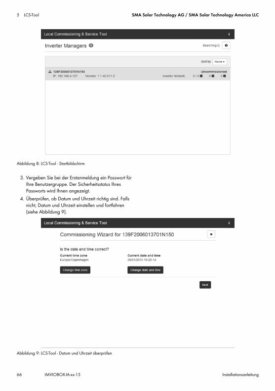
2. Der Bildschirm zeigt jetzt eine Liste aller Inverter Manager (siehe Abbildung 8). Zum Start des Assistenten klicken Sie den zu konfigurierenden Inverter Manager an. Durch Anklicken des Inverter Managers werden die vom Inverter Manager gefundenen Wechselrichter angezeigt. Nicht in Betrieb genommene Wechselrichter (kein zugewiesener Grid-Code) werden mit einem blauen Quadrat zusammen mit ihrer Software-Version aufgeführt.
HINWEISDem LAN 1 Port des Inverter Managers muss vom DHCP-Server, der an den LAN 1 Port angeschlossen ist, eine IP-Adresse zugewiesen werden.Dem Inverter Manager kann auch manuell eine IP-Adresse zugewiesen werden.Es ist wichtig, dass der PC, auf dem das LCS-Tool läuft, an das gleiche IP-Subnetz angeschlossen ist wie der Inverter Manager. Dem Inverter Manager darf keine IP aus dem Anlagennetzwerkbereich 192.168.4.0/24 zugewiesen werden.Der LAN 2 Port ist ausschließlich für die Wechselrichter bestimmt.
A LCS-ToolB Router (DHCP empfohlen)C Inverter ManagerD WechselrichterE LAN 1F LAN 2
5 LCS-Tool SMA Solar Technology AG / SMA Solar Technology America LLC
66 IMVIOBOX-IA-xx-15 Installationsanleitung
Abbildung 8: LCS-Tool - Startbildschirm
3. Vergeben Sie bei der Erstanmeldung ein Passwort für Ihre Benutzergruppe. Der Sicherheitsstatus Ihres Passworts wird Ihnen angezeigt.
4. Überprüfen, ob Datum und Uhrzeit richtig sind. Falls nicht, Datum und Uhrzeit einstellen und fortfahren (siehe Abbildung 9).
Abbildung 9: LCS-Tool - Datum und Uhrzeit überprüfen

SMA Solar Technology AG / SMA Solar Technology America LLC 5 LCS-Tool
Installationsanleitung IMVIOBOX-IA-xx-15 67
5. Optional können Sie einen Namen, einen Standort und Besitzer des Inverter Managers vergeben (siehe Abbildung 10).
Abbildung 10: LCS-Tool - Anlagendetails
6. Eine Liste der durch den ausgewählten Inverter Manager identifizierten Wechselrichter wird angezeigt (siehe Abbildung 11).
Prüfen, ob alle Wechselrichter vorhanden sind. Es ist möglich, mit der Konfiguration der aufgeführten Wechselrichter fortzufahren, selbst wenn nicht alle Wechselrichter gefunden werden. Die unentdeckten Wechselrichter können später noch konfiguriert werden.

5 LCS-Tool SMA Solar Technology AG / SMA Solar Technology America LLC
68 IMVIOBOX-IA-xx-15 Installationsanleitung
Abbildung 11: LCS-Tool - Liste der angeschlossenen Wechselrichter
7. Wählen Sie das gewünschte Land aus der Liste der verfügbaren Optionen für die Wechselrichter im Netzwerk (siehe Abbildung 12).
8. Wählen Sie den gewünschten Grid-Code aus der Liste der verfügbaren Optionen für das ausgewählte Land aus. Im Bedarfsfall einen kundenspezifischen
Grid-Code durch Anklicken der Schaltfläche [Load] laden (siehe Abbildung 12). Die Schaltfläche [Create] ist inaktiv und kann nicht verwendet werden.
Abbildung 12: LCS-Tool - Land und Grid-Code auswählen
SMA Solar Technology AG / SMA Solar Technology America LLC 5 LCS-Tool
Installationsanleitung IMVIOBOX-IA-xx-15 69
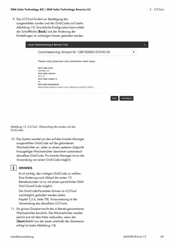
9. Das LCS-Tool fordert zur Bestätigung des ausgewählten Landes und des Grid-Codes auf (siehe Abbildung 13). Eine falsche Konfiguration kann mittels der Schaltfläche [Back] und der Änderung der Einstellungen im vorherigen Fenster geändert werden.
Abbildung 13: LCS-Tool - Überprüfung des Landes und des Grid-Codes
10. Das System wendet nun den auf dem Inverter Manager ausgewählten Grid-Code auf die gefundenen Wechselrichter an. Jeder zu einem späteren Zeitpunkt hinzugefügte Wechselrichter übernimmt automatisch denselben Grid-Code. Pro Inverter Manager ist nur die Anwendung von einem Grid-Code möglich.
11. Ein grünes Quadrat macht den in Betrieb genommenen Wechselrichter kenntlich. Die Wechselrichter werden jedoch erst mit dem Netz verbunden, wenn der [Start]-Befehl von der Leiste unterhalb des Startmenüs erfolgt ist (siehe Abbildung 14).
HINWEISEs ist wichtig, den richtigen Grid-Code zu wählen. Eine Änderung nach Ablauf der ersten 10 Betriebsstunden ist nur mit einem persönlichen SMA Grid Guard-Code möglich.Die Grid-Code-Parameter können im LCS-Tool nachträglich geändert werden (siehe Kapitel 5.2.6, Seite 78). Voraussetzung ist die Verwendung des aktuellsten LCS-Tools.

5 LCS-Tool SMA Solar Technology AG / SMA Solar Technology America LLC
70 IMVIOBOX-IA-xx-15 Installationsanleitung
Abbildung 14: LCS-Tool - Liste aller an den Inverter Manager angeschlossenen Wechselrichter
12. Wenn genügend PV-Leistung vorhanden ist und die Grid-Code-Bedingungen erfüllt sind, beginnt der Wechselrichter mit dem Betrieb.
13. Bei Inbetriebnahme ist es möglich, einen Inbetriebnahmebericht im Menü Reports herunterzuladen. Der Bericht enthält alle Informationen über die Wechselrichtereinstellungen, einschließlich der eingestellten Trennwerte für die einzelnen Wechselrichter. Über das Ordnersymbol im Menü Reports ist es möglich, ein Verzeichnis Inbetriebnahmeberichten (inklusive Gird-Code Informationen) zu öffnen (siehe Abbildung 15).
Abbildung 15: LCS-Tool - Inbetriebnahmebericht

SMA Solar Technology AG / SMA Solar Technology America LLC 5 LCS-Tool
Installationsanleitung IMVIOBOX-IA-xx-15 71
5.2 Betrieb5.2.1 Passwort vergessen
Abbildung 16: LCS-Tool - Passwort vergessen
Wenn Sie das Passwort für die Benutzeroberfläche vergessen haben, dann können Sie sich mit einem Personal Unlocking Key (PUK) einloggen. Für jede Benutzergruppe gibt es einen eigenen PUK.
Vorgehen:1. PUK anfordern (siehe „Antrag für die Bestellung einer
PUK“ unter www.SMA-Solar.com).2. LCS-Tool öffnen.3. Benutzergruppe User oder Installer wählen.4. PUK anstelle des Passworts eingeben.5. Das Menü Setup aufrufen.6. Unter Password das Passwort der gewünschten
Benutzergruppe ändern.7. Um die Änderungen zu speichern, [Save] wählen.

5 LCS-Tool SMA Solar Technology AG / SMA Solar Technology America LLC
72 IMVIOBOX-IA-xx-15 Installationsanleitung
5.2.2 Grid-Code ändern
Abbildung 17: LCS-Tool - SMA Grid Guard-Code eingeben
Um den Inverter Manager nach den ersten 10 Betriebsstunden zurückzusetzen und einen neuen Länderdatensatz zu wählen, verwenden Sie Ihren SMA Grid Guard-Code unter der Benutzergruppe Installer (siehe Zertifikat „Bestellformular für den SMA Grid Guard-Code“ unter www.SMA-Solar.com).
Vorgehen:1. LCS-Tool öffnen.2. Als Installer anmelden.3. Das Menü Service aufrufen.4. Unter Grid Guard im Feld Individual access code
Ihren SMA Grid Guard-Code eingeben.5. Um die Änderungen zu speichern, [Save] wählen.
☑ Unter dem Menü Setup steht ein neuer Menüpunkt General zur Verfügung.

SMA Solar Technology AG / SMA Solar Technology America LLC 5 LCS-Tool
Installationsanleitung IMVIOBOX-IA-xx-15 73
5.2.3 Firmware-Update durchführen
Abbildung 18: LCS-Tool - Manuelles Firmware-Update
Sie können manuell ein Firmware-Update des Inverter Managers durchführen. Es wird empfohlen, die aktuellste Version des LCS-Tools zu verwenden. Das LCS-Tool ist im Downloadbereich unter www.SMA-Solar.com verfügbar.
Vorgehen:1. LCS-Tool öffnen.2. Als User oder Installer anmelden.3. Das Menü Service aufrufen.4. Unter Software Update die Registerkarte Inverter
manager wählen.5. Um das Update durchzuführen, [Start update]
wählen. ☑ Das Update wird jetzt durchgeführt.
Beschädigung der Produkte durch Unterbrechung des UpdatevorgangsWird die Verbindung zwischen dem Inverter Manager und dem PC getrennt, kann es zu einem Geräteschaden kommen.
• Die Verbindung zwischen dem Inverter Manager und dem PC nicht trennen.
• Den PC und den Inverter Manager nicht von der Stromversorgung trennen.
• Den PC nicht in den Energiesparmodus versetzen.

5 LCS-Tool SMA Solar Technology AG / SMA Solar Technology America LLC
74 IMVIOBOX-IA-xx-15 Installationsanleitung
5.2.4 Anlagenfallback einstellen
Abbildung 19: LCS-Tool - Fallback-Parameter einstellen
Für den Fall einer Kommunikationsunterbrechung zwischen dem Inverter Manager und einer übergeordneten Regelungseinheit (z. B. SCADA-System oder Power Plant Controller) kann ein Anlagenfallback konfiguriert werden. Der übergeordnete Anlagenfallback kann ausschließlich über das LCS-Tool konfiguriert werden. Um die Werte für einen übergeordneten Fallback einzustellen, verwenden Sie Ihren SMA Grid Guard-Code unter der Benutzergruppe Installer (siehe Kapitel 5.2.2, Seite 72).
Vorgehen:1. LCS-Tool öffnen.2. Als Installer anmelden.3. Das Menü Setup aufrufen.4. Unter Plant fallback die entsprechenden Werte
eingeben.5. Um die Änderungen zu speichern, [Save] wählen.

SMA Solar Technology AG / SMA Solar Technology America LLC 5 LCS-Tool
Installationsanleitung IMVIOBOX-IA-xx-15 75
5.2.5 Limited Export einstellen
Abbildung 20: LCS-Tool - Limited Export einstellen
Mit der Funktion Limited Export in Verbindung mit einem Modbus-fähigen Energiezähler, kann eine maximal definierte Ausgangsleistung am Netzanschlusspunkt bereitgestellt werden (siehe Abbildung 22). Dabei wird die Gesamtnennleistung aller am Inverter Manager angeschlossenen Wechselrichter berücksichtigt. Der Wechselrichter wird auf die maximale Ausgangsleistung am Netzanschlusspunkt um den Betrag des Eigenverbrauchs erhöht oder reduziert. Dabei wird die Begrenzung am Netzanschlusspunkt eingehalten, während alle angeschlossenen Verbraucher weiterhin mit Energie aus den Wechselrichtern versorgt werden können.Der maximale Sollwert der Anlagenleistung kann fest oder dynamisch vergeben werden:
• Feste Vorgabe: Den Parameter Active Power (P_ref) für die Wirkleistungsbegrenzung im Menü Inverter Parameter unter Protection settings > Support settings > Immediate controls einstellen (siehe Kapitel 5.2.6 „Wechselrichter-Parameter ändern“, Seite 78).
• Dynamische Vorgabe: Der Sollwert der Anlagenleistung kann zusätzlich dynamisch durch die I/O Box, per Modbus und die
Direktvermarkterschnittstelle begrenzt werden. Wird der Wert dynamisch gesetzt, wird dadurch der im LCS-Tool gesetzte Parameter Active Power (P_ref) überschrieben. Dies gilt im regulären Einspeisebetrieb sowie bei aktivierter Limited Export Funktion. Ohne aktivierte Limited Export Funktion ist eine lastabhängige Regelung nicht möglich. Die Wechselrichter werden dann direkt auf den Sollwert begrenzt (siehe Abbildung 23).
Vorgehen:1. LCS-Tool öffnen.2. Als Installer anmelden.3. Das Menü Setup aufrufen.4. Unter Limited Export die entsprechenden Werte
eingeben.5. Um die Änderungen zu speichern, [Save] wählen.
Die Parameter Meter-IP--Adress, Meter Modbus Port, Meter Modbus Unit ID und Meter Power Modbus Register dienen der Konfiguration des Energiezählers. Mit dem Sonderfall des Limited Export „Zero-Export“ kann der Einspeisebetrieb in das öffentliche Stromnetz vollständig verhindert werden. Der Parameter Safety Offset ist ein Sicherheitsabstand zur eingestellten maximalen Ausgangsleistung am Netzanschlusspunkt, der in % der Anlagennennleistung angegeben wird.

5 LCS-Tool SMA Solar Technology AG / SMA Solar Technology America LLC
76 IMVIOBOX-IA-xx-15 Installationsanleitung
Aus Sicherheitsgründen und zum Ausgleich von plötzlichen Lastsprüngen wird dieser Sicherheitsabstand vergeben, um den Abstand zum Sollwert herzustellen. Bei Aktivierung wird der Sollwert um den Sicherheitswert reduziert. Somit ist die Einspeiseleistung immer kleiner als der tatsächliche Sollwert.Der Parameter Meter Connection Timeout ist die Zeit in Sekunden, nach der die Anlagenleistung nach einem Kommunikationsabbruch zum Energiezähler auf 0 W geregelt wird.Um eine Übersicht über die aktuellen Anlagenwerte zu erhalten, das Menü Status aufrufen und Overview wählen (siehe Abbildung 21).
Abbildung 21: LCS-Tool - Übersicht über aktuelle Anlagenwerte
Regelung per ModbusUm eine dauerhafte Begrenzung einzustellen, im Modbus-Register 40349 den gewünschten Wert setzen.Um den Wechselrichter trotz aktivierter Limited Export Funktion umgehend vom öffentlichen Stromnetz zu trennen, im Modbus-Register 40348 den Wert „0“ setzen.Für Informationen zur Modbus-Schnittstelle siehe Technische Information „SUNNY TRIPOWER 60 / SUNNY HIGHPOWER PEAK1 - SunSpec®-Modbus®-Schnittstelle“ unter www.SMA-Solar.com.
SMA Solar Technology AG / SMA Solar Technology America LLC 5 LCS-Tool
Installationsanleitung IMVIOBOX-IA-xx-15 77
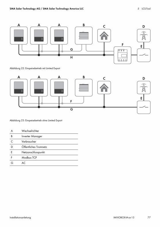
Abbildung 22: Einspeisebetrieb mit Limited Export
Abbildung 23: Einspeisebetrieb ohne Limited Export
A WechselrichterB Inverter ManagerC VerbraucherD Öffentliches TromnetzE NetzanschlusspunktF Modbus TCPG AC

5 LCS-Tool SMA Solar Technology AG / SMA Solar Technology America LLC
78 IMVIOBOX-IA-xx-15 Installationsanleitung
5.2.6 Wechselrichter-Parameter ändern
Abbildung 24: LCS-Tool - Wechselrichter-Parameter ändern
Alle Wechselrichter-Parameter sind Grid-Guard-geschütz und benötigen zum Ändern den Grid-Guard-Code. Um die Einstellungen für die Wechselrichter zu verändern, verwenden Sie Ihren SMA Grid Guard-Code unter der Benutzergruppe Installer (siehe Kapitel 5.2.2, Seite 72).
Vorgehen:1. LCS-Tool öffnen.2. Als Installer anmelden.3. Das Menü Setup aufrufen.4. Unter Inverter Parameter die entsprechenden Werte
eingeben.5. Um die Änderungen zu speichern, [Save] wählen.
Wechselrichter-Parameter aktivieren/deaktivierenUm einen Parameter zu aktivieren und deaktivieren, mit der linken Maustaste auf den Parameter doppelklicken. Bei aktiven Parametern sind die Eingabefelder und Schaltflächen für die Eingabe freigegeben. Inaktive Parameter sind mit disable gekennzeichnet.

SMA Solar Technology AG / SMA Solar Technology America LLC 5 LCS-Tool
Installationsanleitung IMVIOBOX-IA-xx-15 79
Abbildung 25: LCS-Tool - Wechselrichter-Parameter aktivieren/deaktivieren
Vorzeichen bei Power Factor-Parametern ändernUm das Vorzeichen bei Power Factor-Parametern zu ändern, mit der linken Maustaste auf das Vorzeichen klicken.
Abbildung 26: LCS-Tool - Vorzeichen ändern

5 LCS-Tool SMA Solar Technology AG / SMA Solar Technology America LLC
80 IMVIOBOX-IA-xx-15 Installationsanleitung
I/O Box-Parameter einstellenUm die Parameter im Untermenü I/O Box einzugeben, mit der rechten Maustaste auf die Eingabefelder klicken.
Abbildung 27: LCS-Tool - I/O Box-Parameter einstellen
5.2.7 LogsIm Menü Logs können Informationen zu Ereignissen, Leistungsdaten, Parametervorgaben und geänderten Parametern der Wechselrichter abgerufen werden.
Abbildung 28: LCS-Tool - Logs
IMVIOBOX-IA-xx-15 | Version 1.5 ESPAÑOL
1 Indicaciones sobre este documento1.1 Área de validezEste documento es válido para el SMA Inverter Manager, la SMA Digital I/O Box y la LCS-Tool.
1.2 Grupo de destinatariosLas actividades descritas en este documento deben realizarlas solamente especialistas, que han de contar con esta cualificación:
• Formación profesional para la instalación y puesta en marcha de equipos eléctricos
• Formación sobre la gestión de peligros y riesgos relativos a la instalación y el manejo de equipos eléctricos y plantas
• Formación profesional sobre la instalación y la configuración de sistemas informáticos
• Conocimientos sobre los procedimientos y el funcionamiento de un inversor
• Conocimiento de las leyes, normativas y directivas aplicables
• Conocimiento y seguimiento de este documento y de todas sus indicaciones y advertencias de seguridad
1.3 Símbolos
1.4 Nomenclatura
Símbolo ExplicaciónAdvertencia que, de no ser observada, causa la muerte o lesiones físicas gravesAdvertencia que, de no ser observada, puede causar la muerte o lesiones físicas gravesAdvertencia que, de no ser observada, puede causar lesiones físicas leves o de gravedad media
Advertencia que, de no ser observada, puede causar daños materialesInformación importante para un tema u objetivo concretos, aunque no relevante para la seguridad
☐ Requisito necesario para alcanzar un objetivo determinado
☑ Resultado deseado✖ Posible problema
Denominación completa Denominación utilizada en este documento
SMA Inverter Manager Inverter ManagerSMA Digital I/O Box I/O BoxLocal Commissioning and Service Tool (herramienta local de puesta en marcha y servicio técnico)
LCS-Tool
SMA Solar Technology AG SMASMA Solar Technology America LLCSMA Solar Technology Canada Inc.
Símbolo Explicación
Instrucciones de instalaciónSMA INVERTER MANAGER/ SMA DIGITAL I/O BOX/ LCS-TOOL
2 Seguridad SMA Solar Technology AG / SMA Solar Technology America LLC
30 IMVIOBOX-IA-xx-15 Instrucciones de instalación
2 Seguridad2.1 Uso previstoEl Inverter Manager es un equipo que monitoriza y controla hasta 42 Sunny Tripower 60 y Sunny Highpower Peak1 en plantas fotovoltaicas descentralizadas.La I/O Box es una interfaz de función para un Inverter Manager. La I/O Box recibe a través de señales digitales órdenes para la gestión de red y envía las especificaciones al Inverter Manager.El Inverter Manager recibe las especificaciones de la I/O Box y controla en consecuencia todos los inversores de la planta fotovoltaica. El Inverter Manager y la I/O Box deben emplearse únicamente en interiores y con los inversores de SMA Sunny Tripower 60 y Sunny Highpower Peak1.La LCS-Tool es necesaria para la puesta en marcha y el mantenimiento de los inversores mediante el SMA Inverter Manager. La LCS-Tool actúa como interfaz de usuario principal de la planta fotovoltaica.Utilice siempre el producto de acuerdo con las indicaciones de la documentación adjunta y observe las normativas y directivas locales vigentes. Cualquier otro uso puede causarle lesiones al usuario o daños materiales. Por razones de seguridad se prohíben las modificaciones del producto, así como la incorporación de componentes que no hayan sido recomendados o distribuidos específicamente por SMA para el producto. Realizar modificaciones y remodelaciones no autorizadas anula los derechos de garantía y la autorización de operación. Cualquier uso del producto distinto al descrito en el uso previsto se considerará inadecuado. La placa de características debe permanecer colocada en el producto en todo momento. La documentación adjunta es parte integrante del producto.
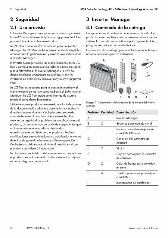
3 Inverter Manager3.1 Contenido de la entregaCompruebe que el contenido de la entrega de todos los productos esté completo y que no presente daños externos visibles. En caso de que no esté completo o presente daños, póngase en contacto con su distribuidor.El contenido de la entrega puede incluir componentes que no sean necesarios para la instalación.
Imagen 1: Componentes del contenido de la entrega del Inverter Manager
Posición Cantidad DenominaciónA 1 Inverter ManagerB 2 Soportes para montaje muralC 1 Soporte para el montaje sobre
carril DIN (35 mm)D 1 Conexión del suministro de
corrienteE 2 VirolasF 1 Caja de bornes para el suministro
de corrienteG 2 Cajas de bornes para conexión
en serieH 4 Tornillos para montaje mural y en
carril DINI 1 Instrucciones de instalación

SMA Solar Technology AG / SMA Solar Technology America LLC 3 Inverter Manager
Instrucciones de instalación IMVIOBOX-IA-xx-15 31
3.2 Montaje del Inverter Manager
3.2.1 Variante 1: Montaje en pared
3.2.2 Variante 2: Montaje en carril DIN
Daños en el producto y los cables debido a la penetración de humedadEl Inverter Manager y la I/O Box no están protegidos contra las salpicaduras de agua. Podría penetrar humedad y dañar los productos y cables.
• El Inverter Manager y la I/O Box deben instalarse en entornos secos; por ejemplo, en interiores o en una carcasa protegida contra salpicaduras de agua (tipo de protección: mínimo IP54 (NEMA 3R)).

3 Inverter Manager SMA Solar Technology AG / SMA Solar Technology America LLC
32 IMVIOBOX-IA-xx-15 Instrucciones de instalación
3.3 Conexión al Inverter Manager3.3.1 Indicaciones de seguridad
3.3.2 Esquema de interconexión
Imagen 2: Esquema de interconexión
Peligro de muerte por descarga eléctricaEn el punto de conexión de la red pública hay tensiones eléctricas que pueden causar la muerte.
• Desconecte el punto de conexión y asegúrese de que no tenga tensión.
Posición DenominaciónA InversorB Ordenador con LCS-ToolC RúterD Estación meteorológica compatible con
SunSpec Alliance (opcional)
E I/O Box (opcional)F Inverter Manager
Posición Denominación

SMA Solar Technology AG / SMA Solar Technology America LLC 3 Inverter Manager
Instrucciones de instalación IMVIOBOX-IA-xx-15 33
3.3.3 Conexión de los inversores y el rúter a través de ethernetAsignación de patillas de las hembrillas de red (LAN 1 y LAN 2):
Imagen 3: Asignación de patillas de las hembrillas de red:
3.3.4 Conexión de la I/O Box y de la estación meteorológica (opcional)
Asignación de patillas de la interfaz serial (RS485) al Inverter Manager:
Imagen 4: Asignación de patillas de la interfaz serial
La I/O Box se conecta al puerto 2 del Inverter Manager. No es necesario contar con una terminación para la interfaz RS485.
Interfaces y datos de la estación meteorológicaA cada Inverter Manager puede conectarse solamente una estación meteorológica. La estación meteorológica se conecta al puerto 1 del Inverter Manager. Son compatibles dos termistores como máximo.El Inverter Manager facilitará estos datos de la estación meteorológica:
Patilla Asignación para 10/100 Mbps
Asignación para 1000 Mbps
1 ETx+ TRD(0)+2 ETx- TRD(0)-3 ERx+ TRD(1)+4 --- TRD(2)+5 --- TRD(2)-6 ERx- TRD(1)-7 --- TRD(3)+8 --- TRD(3)-
No conectar en funcionamientoNo conecte la I/O Box o la estación meteorológica al Inverter Manager si está en funcionamiento. Pueden producirse errores que no se detecten en el momento.
• Desconecte el Inverter Manager de la tensión.
8 1
81
321 4 5
9876
Patilla Asignación1 ---2 ---3 DataB(+)4 DataA(-)5 GND6 ---7 ---8 ---
Datos meteorológicos
SunSpec Modbus TCP
LCS-Tool/FTP-Push
Sunny Portal
Temperatura ambiente y fotovoltaica
Sí Sí Sí
Dirección y velocidad del viento
Sí Sí Sí
Irradiación solar horizontal
Sí Sí Si no se proporciona la irradiación solar inclinada
Irradiación solar inclinada
No Sí Sí

3 Inverter Manager SMA Solar Technology AG / SMA Solar Technology America LLC
34 IMVIOBOX-IA-xx-15 Instrucciones de instalación
3.3.5 Conexión del Inverter Manager al suministro de tensión
Procedimiento:Para conectar el Inverter Manager al suministro de tensión, siga estas indicaciones en el orden descrito.
• Conecte el conductor de protección al Inverter Manager.
• Conecte la fuente de alimentación.
Conexión del conductor de protección al Inverter ManagerSG: El contacto de protección por puesta a tierra (Shielded Ground, SG; también llamado Protected Ground), se encuentra en la vista mostrada en la parte superior, en la hembrilla de la toma de corriente.Procedimiento:
• Ponga a tierra el Inverter Manager. Para ello, conecte el conductor de protección al tornillo de puesta a tierra del Inverter Manager. Que la toma a tierra sea adecuada y el trazado de los cables, correcto, contribuye a limitar posibles emisiones de interferencias causadas por interferencias electromagnéticas (EMI).
Conexión de la fuente de alimentación
SMA recomienda utilizar la fuente de alimentación para carril DIN disponible como accesorio (número de pedido: CLCON-PWRSUPPLY)* .
Procedimiento:1. Monte la fuente de alimentación (consulte las
instrucciones del fabricante).2. Conecte el cable de conexión a la fuente de
alimentación (consulte las instrucciones del fabricante). Recorte los conductores que no sean necesarios hasta el revestimiento del cable y anote el color de los conductores.
3. Conecte el cable de conexión a la caja de bornes del suministro de tensión (de 9 V CC a 36 V CC). Compruebe que el conductor de puesta a tierra apantallado esté conectado con el terminal de toma a tierra.
4. Conecte la caja de bornes del suministro de tensión con la fuente de alimentación conectada a la hembrilla “Power Input” del Inverter Manager.
5. Conecte el cable de conexión de CA a la fuente de alimentación (consulte las instrucciones del fabricante).
7. Conecte el otro extremo del cable de conexión CA al suministro de tensión.
8. Conecte el punto de conexión a la red pública.☑ Cuando el led de alimentación se ilumine en verde, el
Inverter Manager está listo para funcionar.
3.4 Conexión ethernet del Inverter ManagerLAN 1 (red de plantas)El puerto LAN 1 del Inverter Manager asignará la dirección IP y la máscara de subred a través de un servidor DHCP externo. Al puerto LAN 1 del Inverter Manager también es posible asignar manualmente una dirección IP.
LAN 2 (red de inversores)El Inverter Manager asignará la dirección IP al inversor.
Restablecimiento del Inverter Manager al DHCP
• Para resetear el Inverter Manager al DHCP, pulse la tecla Power 3 veces en un lapso de 1 segundo.
Peligro de muerte por descarga eléctrica al tocar un producto no conectado a tierraEl contacto con un producto que no está conectado a tierra puede causar descargas eléctricas mortales.
• Asegúrese de que el producto esté integrado en la protección contra sobretensión existente.
• Ponga a tierra la carcasa del producto.
* No está disponible en todos los países.
GND9 to 36 VDC
6.Peligro de muerte por descarga eléctricaEn el punto de conexión de la red pública hay tensiones eléctricas que pueden causar la muerte.
• Desconecte el punto de conexión y asegure contra cualquier reconexión accidental.

SMA Solar Technology AG / SMA Solar Technology America LLC 3 Inverter Manager
Instrucciones de instalación IMVIOBOX-IA-xx-15 35
3.5 Señales led del Inverter Manager
3.6 Datos técnicos
Led Estado ExplicaciónPower Encendido
en verdeEl Inverter Manager está en funcionamiento.
Apagado El Inverter Manager no está en funcionamiento.
LAN Encendido en verde
Modo ethernet 100 Mbps
Encendido en amarillo
Modo ethernet 1000 Mbps (Gigabit)
Apagado Sin actividad o ethernet 10 Mbps
Tx1, Tx2 (P1-P2)
Intermitente en verde
Transferencia de datos a través de puertos en serie P1-P2
Apagado Sin transferencia de datos a través de puertos en serie P1-P2
Rx1, Rx2 (P1-P2)
Intermitente en verde
Recepción de datos a través de puertos en serie P1-P2
Apagado Sin recepción de datos a través de puertos en serie P1-P2
Suministro de tensiónTensión de entrada De 9 Vcc a 36 VccConsumo de potencia < 20 WSección máxima del cable 1,3 mm² (16 AWG)
Datos generalesDimensiones (anchura x altura x profundidad)
160 mm x 125 mm x 49 mm
(6,3 in x 4,9 in x 1,9 in)Peso 940 g (2 lbs)Tipo de montaje Montaje en pared o carril
DINRango de temperatura de funcionamiento
De -40 °C a +75 °C (De -40 °F a +167 °F)
Humedad relativa del aire, sin condensación
5 % a 95 %
Homologaciones UL 508, UL 60950-1, CSA C22.2 n.º
60950-1-07, EN 60950-1, CCC (GB9254,
GB17625.1), EN 55022, clase A, EN 61000-3-2, clase D, EN 61000-3-3,
EN 55024, FCC parte 15, subparte B, clase A
InterfacesInterfaz de usuario LCS-Tool para ordenador a
través de ethernetInterfaz para el inversor LAN 2, interfaz ethernet
(RJ45)Interfaz para la red externa LAN 1, interfaz ethernet
(RJ45)Interfaz para la I/O Box (opcional)
RS485 (D-Sub 9)/SunSpec Modus
Interfaz de sensores para estaciones meteorológicas compatibles con SunSpec (opcionales)
RS485 (D-Sub 9)/SunSpec Modus
Longitud máxima del cable para la conexión ethernet
100 m (328 ft)
Longitud máxima del cable para el cableado RS485
1200 m (4000 ft)
Monitorización de la planta
Sunny Portal, SunSpec Modbus TCP
Norma de potencia efectiva y norma de potencia reactiva
Valor constante, curva o control remoto a través de SunSpec Modbus TCP con
I/O BoxVelocidades de transmisión compatibles para el funcionamiento de una estación meteorológica
9600, 19200, 57600, 115200
Fuente de alimentación (recomendado)Modelo comercial CLCON-PWRSUPPLY*
* No está disponible en todos los países.
Entrada De 100 Vca a 240 VcaSalida 24 Vcc; 2,5 ATemperatura ambiente -25 °C a +70 °CHomologaciones CE, UL
Datos generales

4 I/O Box SMA Solar Technology AG / SMA Solar Technology America LLC
36 IMVIOBOX-IA-xx-15 Instrucciones de instalación
4 I/O Box4.1 Contenido de la entregaCompruebe que el contenido de la entrega de todos los productos esté completo y que no presente daños externos visibles.En caso de que no esté completo o presente daños, póngase en contacto con su distribuidor.El contenido de la entrega puede incluir componentes que no sean necesarios para la instalación.
Imagen 5: Contenido de la entrega de la I/O Box
4.2 Montaje de la I/O Box
4.2.1 Variante 1: Montaje en pared
4.2.2 Variante 2: Montaje en carril DIN
4.3 Conexión a la I/O Box4.3.1 Vista general
Imagen 6: Vista general de la conexión I/O Box
Posición Cantidad DenominaciónA 1 I/O BoxB 1 CDC 1 Instrucciones breves para la
instalación
Daños en el producto y los cables debido a la penetración de humedadEl Inverter Manager y la I/O Box no están protegidos contra las salpicaduras de agua. Podría penetrar humedad y dañar los productos y cables.
• El Inverter Manager y la I/O Box deben instalarse en entornos secos; por ejemplo, en interiores o en una carcasa protegida contra salpicaduras de agua (tipo de protección: mínimo IP54 (NEMA 3R)).
A B C
1 2
1 2 3
12
3456
7
8 9 01
2
3456
7
8 9 01
2
3456
7
8 9 01
2
3456
7
8 9 0
D1+
D1-
GND
D2+
D2-
P1
P2
V+
V-
X10
X1
DualRun
RepInitial
COM0
DI0
DI1
DI2
DI3
DI4
DI5
DI6
DI7
COM1
DIO0
DIO1
DIO2
DIO3
GND
DIO4
DIO5
DIO6
DIO7
GND
A
C
D
COM0
DI0
DI1
DI2
DI3
DI4
DI5
GND
B
E

SMA Solar Technology AG / SMA Solar Technology America LLC 4 I/O Box
Instrucciones de instalación IMVIOBOX-IA-xx-15 37
4.3.2 Conexión del Inverter Manager
Asignación de patillas del borne RS485 (consulte capítulo 3.3.4, página 33):
4.3.3 Conexión de las fuentes de la señalConexión de una fuente de señal con contacto de relé sin potencial
Conexión de una fuente de señal (de 10 a 30 V) con señales de salida digitales
4.3.4 Conexión de la I/O Box al suministro de tensiónConecte la línea de conexión de 12 a 36 V CC con el borne del suministro de tensión. Conecte la toma a tierra de la línea de conexión al borne “V-” y acople la patilla de toma a tierra (GND) si hay una toma a tierra disponible.
Posición DenominaciónA Entradas digitales para la conexión a una
fuente de señal (pueden ocuparse las entradas de DI0 a DI5; el resto de entradas carecen de función)
B Mantener el ajuste de fábrica: X1 = 1, X10 = 0
C Conexión del Inverter ManagerD Conexión del suministro de corrienteE Mantener el ajuste de fábrica: 1 = Dual,
2 = Initial
No conectar en funcionamientoNo conecte la I/O Box al Inverter Manager si está en funcionamiento. Pueden producirse errores que no se detecten en el momento.
• Desconecte el Inverter Manager de la tensión.• Conecte la I/O Box con el Inverter Manager.• Vuelva a conectar el Inverter Manager al
suministro de tensión.
Patilla AsignaciónD2- ---D2+ ---GND GNDD1- DataA(-)D1+ DataB(+)
(5) GND
(3) Data B (+)D1+(4) Data A (−)/D1−
Patilla AsignaciónV- / V+ Suministro de tensión 24 Vcc
(12 Vcc a 36 Vcc)

4 I/O Box SMA Solar Technology AG / SMA Solar Technology America LLC
38 IMVIOBOX-IA-xx-15 Instrucciones de instalación
4.3.5 Señales led de la I/O Box
4.4 Datos técnicos
Diámetro de los hilos de conexiónPor motivos de seguridad, los hilos de conexión del suministro de corriente deben tener un diámetro mínimo de 2 mm².
Led Estado ExplicaciónPower Encendido en
amarilloLa I/O Box está en funcionamiento.
Apagado La I/O Box no está en funcionamiento.
Ready Encendido en verde
El sistema está listo para funcionar.
El verde parpadea una vez por segundo.
Se ha activado la función de “Localizar”.
Intermitente en verde cada 0,5 segundos
El firmware se actualiza.
Intermitente en verde
Si el led verde se enciende 5 segundos y se apaga por 5 segundos, el sistema se encuentra en “Safe Mode”.
Apagado El sistema no está listo para funcionar.
Puerto 1
Intermitente en verde
Se envían o reciben datos.
Puerto 2
Intermitente en amarillo
Se envían o reciben datos.
Datos del sistemaSuministro de corriente 24 Vcc nominal,
De 12 Vcc a 36 VccCableado Cable I/O máx. 25 mm²
(4 AWG)Dimensiones 27,8 mm x 124 mm x 84 mm
(1.09 x 4.88 x 3.31 in)Peso < 200 g
Rango de temperatura de funcionamiento
Módulo estándar: De -10 °C a +75 °C (De 14 °F a 167 °F)
Temperatura de almacenamiento
De -40 °C a +85 °C (De -40 °F a 185 °F)
Humedad relativa del aire, sin condensación
5 % a 95 %
Altitud de funcionamiento < 2000 mEstándares y certificaciones
UL 508, CE, FCC clase A
Entrada digitalTipo de sensor Contacto sin potencial
(NPN o PNP), contacto con potencial
Modo I/O DI o contador de eventosContacto sin potencial Encendido = fallo a tierra
Apagado = OpenContacto con potencial (DI a COM)
Encendido = de 10 Vcc a 30 Vcc
Apagado = de 0 Vcc a 3 Vcc
Tensión de aislamiento 3000 Vcc o 2000 VeffContador/Frecuencia 250 Hz, acumulador
desconectado
Datos del sistema

SMA Solar Technology AG / SMA Solar Technology America LLC 5 LCS-Tool
Instrucciones de instalación IMVIOBOX-IA-xx-15 39
5 LCS-ToolLos inversores y el Inverter Manager deben ponerse en marcha con la herramienta de puesta en marcha y mantenimiento local (LCS-Tool). Es necesario realizar la puesta en marcha antes de que los inversores puedan conectarse a la red de CA y empezar a inyectar a la red. Se recomienda emplear la versión actual de la LCS-Tool. La LCS-Tool está disponible en la zona de descargas de www.SMA-Solar.com.Requisitos del hardware para la LCS-Tool:
• Ordenador con WindowsTM 7 o superior• 1 GB HDD• 2 GB RAM
La LCS-Tool tiene que estar instalada en una unidad local. El ordenador debe estar conectado al puerto LAN 1 del Inverter Manager a través de un rúter (recomendado DHCP).
Imagen 7: Puesta en marcha de inversores con la LCS-Tool 5.1 Primera puesta en marcha1. Inicie la LCS-Tool. La herramienta muestra una lista de
todos los Inverter Manager identificados. Pueden pasar varios minutos antes de que la LCS-Tool identifique todos los Inverter Manager.
2. La pantalla muestra ahora una lista de todos los Inverter Manager (consulte la imagen 8). Para iniciar el asistente, haga clic en el Inverter Manager que vaya a configurar. Tras seleccionar el Inverter Manager, se visualizan los inversores descubiertos por este. Los inversores que todavía no se han puesto en marcha (no cuentan con un código de red asignado) se presentan con un recuadro azul junto a su versión de software.
INDICACIÓNEl puerto LAN 1 del Inverter Manager debe tener asignada una dirección IP del servidor DHCP al que está conectado el puerto LAN 1.Al Inverter Manager también es posible asignar manualmente una dirección IP.Es importante que el ordenador que aloje la LCS-Tool esté conectado a la misma subred IP que el Inverter Manager. No puede asignarse al Inverter Manager ninguna IP del rango de la red de la planta 192.168.4.0/24.El puerto LAN 2 está destinado exclusivamente a los inversores.
A LCS-ToolB Rúter (recomendado DHCP)C Inverter ManagerD InversorE LAN 1F LAN 2

5 LCS-Tool SMA Solar Technology AG / SMA Solar Technology America LLC
40 IMVIOBOX-IA-xx-15 Instrucciones de instalación
Imagen 8: LCS-Tool - pantalla inicial
3. Cuando inicie sesión por primera vez, introduzca una contraseña para su grupo de usuarios. Se le mostrará el nivel de seguridad de su contraseña.
4. Compruebe que la fecha y la hora sean correctas. De lo contrario, corríjalas y continúe (consulte la imagen 9).
Imagen 9: LCS-Tool - comprobación de fecha y hora

SMA Solar Technology AG / SMA Solar Technology America LLC 5 LCS-Tool
Instrucciones de instalación IMVIOBOX-IA-xx-15 41
5. Si lo desea, puede introducir un nombre, una sede y un propietario del Inverter Manager (consulte la imagen 10).
Imagen 10: LCS-Tool - detalles de la planta
6. Se muestra una lista de inversores identificados por el Inverter Manager (consulte la imagen 11).
Compruebe que todos los inversores estén presentes. Es posible continuar la configuración de los inversores incluidos en la lista aunque no se hayan descubierto todos los inversores. Los inversores no descubiertos se pueden configurar más tarde.

5 LCS-Tool SMA Solar Technology AG / SMA Solar Technology America LLC
42 IMVIOBOX-IA-xx-15 Instrucciones de instalación
Imagen 11: LCS-Tool - lista de inversores conectados
7. Seleccione el país deseado de la lista de opciones disponibles para los inversores de la red (consulte la imagen 12).
8. Seleccione el código de red deseado de la lista de opciones disponibles para el país seleccionado. Si necesita un código de red personalizado,
puede cargarlo mediante el botón [Load] (consulte la imagen 12). El botón [Create] está inactivo y no se puede utilizar.
Imagen 12: LCS-Tool - selección de país y código de red

SMA Solar Technology AG / SMA Solar Technology America LLC 5 LCS-Tool
Instrucciones de instalación IMVIOBOX-IA-xx-15 43
9. La LCS-Tool solicita una confirmación del país y el código de red seleccionados. (consulte la imagen 13). Utilice el botón [Back] y la posibilidad de cambiar los ajustes en las ventanas anteriores para realizar cambios en la configuración.
Imagen 13: LCS-Tool - confirmación de país y código de red
10. El sistema aplica ahora el código de red seleccionado en el Inverter Manager a los inversores descubiertos. Todos los inversores que se añadan con posterioridad asumirán automáticamente el mismo ajuste de red. Solo se permite un ajuste de red por cada Inverter Manager.
11. Un recuadro verde identifica los inversores puestos en marcha. No obstante, los inversores no se conectan a la red hasta que no se les envía un comando de [Start] desde la barra que hay debajo del menú superior (consulte la imagen 14).
INDICACIÓNEs esencial elegir el código de red correcto. Cualquier modificación pasadas las primeras 10 horas de servicio solamente es posible con un código SMA Grid Guard personal.Es posible modificar con posterioridad los parámetros de código de red (consulte el capítulo 5.2.6, página 52). El requisito para ello es emplear la LCS-Tool actual.

5 LCS-Tool SMA Solar Technology AG / SMA Solar Technology America LLC
44 IMVIOBOX-IA-xx-15 Instrucciones de instalación
Imagen 14: LCS-Tool - lista de todos los inversores conectados al SMA Inverter Manager
12. Si hay suficiente potencia fotovoltaica y se cumplen las condiciones de ajuste de red, el inversor comienza a funcionar.
13. Tras la puesta en marcha, es posible descargar un informe de puesta en marcha en el menú Reports. El informe contiene toda la información sobre la configuración del inversor, incluidos los valores de desconexión reales de cada inversor. Mediante el símbolo de carpeta en el menú Reports es posible abrir un directorio de informes de puesta en marcha (incluyendo información del código de red) (consulte la imagen 15).
Imagen 15: LCS-Tool - informe de puesta en marcha

SMA Solar Technology AG / SMA Solar Technology America LLC 5 LCS-Tool
Instrucciones de instalación IMVIOBOX-IA-xx-15 45
5.2 Funcionamiento5.2.1 Contraseña olvidada
Imagen 16: LCS-Tool - contraseña olvidada
Si ha olvidado la contraseña de la interfaz de usuario, puede iniciar sesión con una clave personal de desbloqueo (PUK). Cada grupo de usuario tiene su propia clave personal de desbloqueo (PUK).
Procedimiento:1. Solicite el código PUK (consulte “Solicitud de PUK” en
www.SMA-Solar.com).2. Abra LCS-Tool.3. Escoja el grupo de usuarios User o Installer.4. Introduzca el PUK en lugar de la contraseña.5. Acceda al menú Setup.6. Modifique en Password la contraseña del grupo de
usuario deseado.7. Para guardar los cambios, pulse [Save].
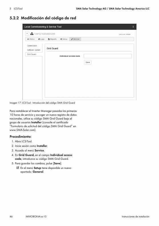
5 LCS-Tool SMA Solar Technology AG / SMA Solar Technology America LLC
46 IMVIOBOX-IA-xx-15 Instrucciones de instalación
5.2.2 Modificación del código de red
Imagen 17: LCS-Tool - Introducción del código SMA Grid Guard
Para restablecer el Inverter Manager pasadas las primeras 10 horas de servicio y escoger un nuevo registro de datos nacionales, utilice su código SMA Grid Guard bajo el grupo de usuarios Installer (consulte el certificado “Formulario de solicitud del código SMA Grid Guard” en www.SMA-Solar.com).
Procedimiento:1. Abra LCS-Tool.2. Inicie sesión como Installer.3. Acceda al menú Service.4. En Grid Guard, en el campo Individual access
code, introduzca su código SMA Grid Guard.5. Para guardar los cambios, pulse [Save].
☑ En el menú Setup tiene disponible un nuevo apartado: General.
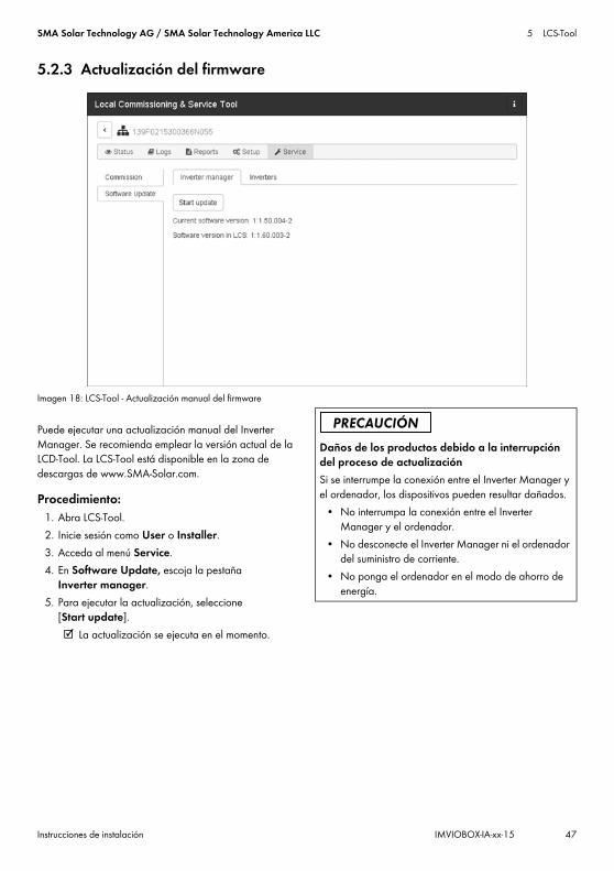
SMA Solar Technology AG / SMA Solar Technology America LLC 5 LCS-Tool
Instrucciones de instalación IMVIOBOX-IA-xx-15 47
5.2.3 Actualización del firmware
Imagen 18: LCS-Tool - Actualización manual del firmware
Puede ejecutar una actualización manual del Inverter Manager. Se recomienda emplear la versión actual de la LCD-Tool. La LCS-Tool está disponible en la zona de descargas de www.SMA-Solar.com.
Procedimiento:1. Abra LCS-Tool.2. Inicie sesión como User o Installer.3. Acceda al menú Service.4. En Software Update, escoja la pestaña
Inverter manager.5. Para ejecutar la actualización, seleccione
[Start update]. ☑ La actualización se ejecuta en el momento.
Daños de los productos debido a la interrupción del proceso de actualizaciónSi se interrumpe la conexión entre el Inverter Manager y el ordenador, los dispositivos pueden resultar dañados.
• No interrumpa la conexión entre el Inverter Manager y el ordenador.
• No desconecte el Inverter Manager ni el ordenador del suministro de corriente.
• No ponga el ordenador en el modo de ahorro de energía.

5 LCS-Tool SMA Solar Technology AG / SMA Solar Technology America LLC
48 IMVIOBOX-IA-xx-15 Instrucciones de instalación
5.2.4 Ajuste del procedimiento de emergencia de la planta
Imagen 19: LCS-Tool - ajuste de los parámetros del procedimiento de emergencia
En caso de que se produzca una interrupción de la comunicación entre el Inverter Manager y una unidad de regulación de orden superior (p. ej. el sistema SCADA o el Power Plant Controller), es posible configurar un procedimiento de emergencia de la planta. El procedimiento de emergencia de la planta de orden superior solo puede configurarse mediante la LCS-Tool. Para ajustar los valores para un procedimiento de emergencia de la planta de orden superior, emplee su código SMA Grid Guard en el grupo de usuarios Installer (consulte el capítulo 5.2.2, página 46).
Procedimiento:1. Abra LCS-Tool.2. Inicie sesión como Installer.3. Acceda al menú Setup.4. Introduzca los valores correspondientes en
Plant fallback.5. Para guardar los cambios, pulse [Save].

SMA Solar Technology AG / SMA Solar Technology America LLC 5 LCS-Tool
Instrucciones de instalación IMVIOBOX-IA-xx-15 49
5.2.5 Ajuste de Limited Export
Imagen 20: LCS-Tool - Ajuste de Limited Export
Con la función Limited Export, en combinación con un contador de energía compatible con Modbus, es posible poner a disposición una potencia de salida máxima definida en el punto de conexión a la red (consulte la imagen 22). De esta forma se tiene en cuenta la potencia nominal total de todos los inversores conectados en el Inverter Manager. La potencia de salida máxima del inversor se aumenta o se reduce en el punto de conexión por el valor del autoconsumo. Así, se cumple la limitación en el punto de conexión a la red mientras que todos los equipos consumidores conectados pueden seguir abasteciéndose con energía de los inversores.El valor de consigna máximo de la potencia nominal de la planta se puede ajustar de forma fija o dinámica:
• Prescripción fija: Ajuste el parámetro Active Power (P_ref) para la limitación de la potencia activa en el menú Inverter Parameter en Protection settings > Support settings > Immediate controls (consulte el capítulo 5.2.6 “Modificación de los parámetros de los inversores”, página 52).
• Prescripción dinámica: Además, el valor de consigna de la potencia nominal de la planta puede limitarse de forma dinámica
mediante la I/O Box, Modbus y la interfaz de comercializadores directos. Si el valor se ajusta de forma dinámica, se sobrescribe de esta forma el parámetro Active Power (P_ref) ajustado en la LCS-Tool. Esto es así en el funcionamiento de inyección habitual y con la función Limited Export activada. La regulación en función del consumo no es posible sin la función Limited Export activada. Los inversores se limitan así directamente al valor de consigna (consulte la imagen 23).
Procedimiento:1. Abra LCS-Tool.2. Inicie sesión como Installer.3. Acceda al menú Setup.4. Introduzca los valores correspondientes en Limited
Export.5. Para guardar los cambios, pulse [Save].
Los parámetros Meter-IP--Adress, Meter Modbus Port, Meter Modbus Unit ID y Meter Power Modbus Register sirven para configurar el contador de energía.El funcionamiento de inyección en la red pública puede evitarse completamente con el caso excepcional del Limited Export “Zero-Export”.

5 LCS-Tool SMA Solar Technology AG / SMA Solar Technology America LLC
50 IMVIOBOX-IA-xx-15 Instrucciones de instalación
El parámetro Safety Offset es una distancia de seguridad de la salida de potencia máxima ajustada en el punto de conexión a la red que se indica en % de la potencia nominal de la planta. Esta distancia de seguridad se elige por razones de seguridad y para nivelar variaciones de carga repentinas para establecer la distancia al valor de consigna. Al activarse, el valor de consigna disminuye según el valor de seguridad. De esta manera la potencia inyectada es siempre menor que el valor de consigna real.El parámetro Meter Connection Timeout es el tiempo en segundos tras el cual la potencia nominal de la planta se limita a 0 W tras una interrupción de comunicación con el contador de energía.Para obtener una vista general de los valores actuales de la planta, abra el menú Status y seleccione Overview (consulte la imagen 21).
Imagen 21: LCS-Tool - Vista general sobre los valores actuales de la planta Control por Modbus
Para configurar una limitación permanente, ajuste el valor deseado en el registro Modbus 40349.Para desconectar inmediatamente el inversor de la red pública a pesar de tener la función Limited Export activada, ajuste en el registro Modbus 40348 el valor “0”.Para obtener más información sobre la interfaz Modbus consulte la información técnica “SUNNY TRIPOWER 60 / SUNNY HIGHPOWER PEAK1 - SunSpec® Modbus® Interface” en www.SMA-Solar.com.

SMA Solar Technology AG / SMA Solar Technology America LLC 5 LCS-Tool
Instrucciones de instalación IMVIOBOX-IA-xx-15 51
Imagen 22: Funcionamiento de inyección con Limited Export
Imagen 23: Funcionamiento de inyección sin Limited Export
A InversorB Inverter ManagerC Equipo consumidorD Red pública E Punto de conexión a la redF Modbus TCPG CA

5 LCS-Tool SMA Solar Technology AG / SMA Solar Technology America LLC
52 IMVIOBOX-IA-xx-15 Instrucciones de instalación
5.2.6 Modificación de los parámetros de los inversores
Imagen 24: LCS-Tool - Modificación de los parámetros de los inversores
Todos los parámetros de los inversores están protegidos mediante Grid Guard y requieren un código SMA Grid Guard. Para modificar los ajustes de los inversores, emplee su código SMA Grid Guard en el grupo de usuarios Installer (consulte el capítulo 5.2.2, página 46).
Procedimiento:1. Abra LCS-Tool.2. Inicie sesión como Installer.3. Acceda al menú Setup.4. Introduzca los valores correspondientes en Inverter
Parameter.5. Para guardar los cambios, pulse [Save].
Activación/desactivación de los parámetros de inversorPara activar o desactivar un parámetro, haga doble clic en el parámetro con la tecla izquierda del ratón. Para parámetros activos, los campos de entrada y los botones están habilitados. Los parámetros inactivos están identificados con disable.

SMA Solar Technology AG / SMA Solar Technology America LLC 5 LCS-Tool
Instrucciones de instalación IMVIOBOX-IA-xx-15 53
Imagen 25: LCS-Tool - Activación/desactivación de los parámetros de inversor
Modificación del signo de parámetros Power FactorPara modificar el signo de parámetros Power Factor, haga doble clic en el signo con el botón izquierdo del ratón.
Imagen 26: LCS-Tool - modificación del signo

5 LCS-Tool SMA Solar Technology AG / SMA Solar Technology America LLC
54 IMVIOBOX-IA-xx-15 Instrucciones de instalación
Ajuste de parámetros de la I/O BoxPara introducir los parámetros en el submenú I/O Box, haga clic en el campo de entrada con el botón derecho del ratón.
Imagen 27: LCS-Tool - Ajuste de parámetros de la I/O Box
5.2.7 LogsEn el menú Logs es posible consultar información acerca de eventos, datos de rendimiento, configuración de parámetros y parámetros modificados de los inversores.
Imagen 28: LCS-Tool - Logs
IMVIOBOX-IA-xx-15 | Version 1.5 Français
1 Remarques relatives à ce document1.1 Champ d’applicationCe document est valable pour le SMA Inverter Manager, la SMA Digital I/O Box et le LCS-Tool.
1.2 Groupe cibleLes opérations décrites dans le présent document doivent être réalisées uniquement par un personnel qualifié. Le personnel qualifié doit posséder les qualifications suivantes :
• Formation à l’installation et à la mise en service d’appareils électriques
• Formation au comportement à adopter en présence des dangers et des risques inhérents à l’installation et à la manipulation d’appareils et d’installations électriques
• Formation à l’installation et à la configuration des systèmes informatiques
• Connaissances relatives au mode de fonctionnement et à l’exploitation d’un onduleur
• Connaissance des lois, normes et directives pertinentes• Connaissance et respect du présent document avec
toutes les consignes de sécurité et les mises en garde
1.3 Symboles
1.4 Nomenclature
Symbole ExplicationMise en garde dont le non-respect entraîne inévitablement des blessures corporelles graves, voire mortellesMise en garde dont le non-respect peut entraîner des blessures corporelles graves, voire mortelles
Mise en garde dont le non-respect peut entraîner des blessures corporelles légères ou de moyenne gravitéMise en garde dont le non-respect peut entraîner des dommages matérielsInformation importante sur un thème ou un objectif précis, mais ne relevant pas de la sécurité
☐ Condition qui doit être remplie pour atteindre un objectif précis
☑ Résultat souhaité✖ Problème susceptible de
survenir
Désignation complète Désignation dans ce document
SMA Inverter Manager Inverter ManagerSMA Digital I/O Box I/O BoxLocal Commissioning and Service Tool (outil d’entretien et de mise en service locale)
LCS-Tool
SMA Solar Technology AG SMASMA Solar Technology America, LLCSMA Solar Technology Canada Inc.
Symbole Explication
Instructions d’installationSMA INVERTER MANAGER / SMA DIGITAL I/O BOX / LCS-TOOL

2 Sécurité SMA Solar Technology AG / SMA Solar Technology America LLC
82 IMVIOBOX-IA-xx-15 Instructions d’installation
2 Sécurité2.1 Utilisation conformeL’Inverter Manager est un dispositif de surveillance et de pilotage de 42 Sunny Tripower 60 et Sunny Highpower Peak1 au maximum dans des installations photovoltaïques décentralisées.La I/O Box est une interface fonctionnelle pour 1 SMA Inverter Manager. La I/O Box reçoit des commandes pour le système de gestion du réseau par le biais de signaux numériques et envoie les consignes au SMA Inverter Manager.Le SMA Inverter Manager reçoit les consignes de la I/O Box et pilote tous les onduleurs de l’installation en conséquence. Le SMA Inverter Manager et la I/O Box ne doivent être exploités qu’à l’intérieur et exclusivement avec le Sunny Tripower 60 et Sunny Highpower Peak1.Le LCS-Tool est nécessaire pour la mise en service et l’entretien des onduleurs, par l’intermédiaire du SMA Inverter Manager. Le LCS-Tool sert d’interface utilisateur primaire pour l’installation photovoltaïque.Utilisez ce produit exclusivement en conformité avec la documentation fournie ainsi qu’avec les normes et directives en vigueur sur le site. Tout autre usage peut compromettre la sécurité des personnes ou entraîner des dommages matériels. Pour des raisons de sécurité, il est strictement interdit d’apporter des modifications au produit ou de monter des composants qui ne sont pas expressément recommandés ni distribués par SMA pour le produit. Toute modification ou transformation non autorisée entraîne l’annulation des droits de garantie et de l’autorisation d’exploitation. Toute utilisation du produit différente de celle décrite dans l’utilisation conforme est considérée comme non conforme. La plaque signalétique doit être apposée en permanence sur le produit. Les documents joints font partie intégrante du produit.
3 Inverter Manager3.1 Contenu de la livraisonVérifiez si la livraison est complète pour chaque produit et ne présente pas de dommage apparent. En cas de livraison incomplète ou de dommages, contactez votre revendeur.La fourniture peut comporter d’autres éléments qui ne soient pas nécessaires dans le cadre de l’installation.
Figure 1: Éléments du contenu de livraison du SMA Inverter Manager
Position Quantité DésignationA 1 Inverter ManagerB 2 Supports pour le montage muralC 1 Support pour montage sur rail
DIN (35 mm DIN rail)D 1 Raccordement pour l’alimentation
en courantE 2 Embouts de câblageF 1 Plaque à bornes pour
l’alimentation en courantG 2 Bornier pour le raccordement
sérieH 4 Vis pour le montage mural ou sur
rail DINI 1 Instructions d’installation
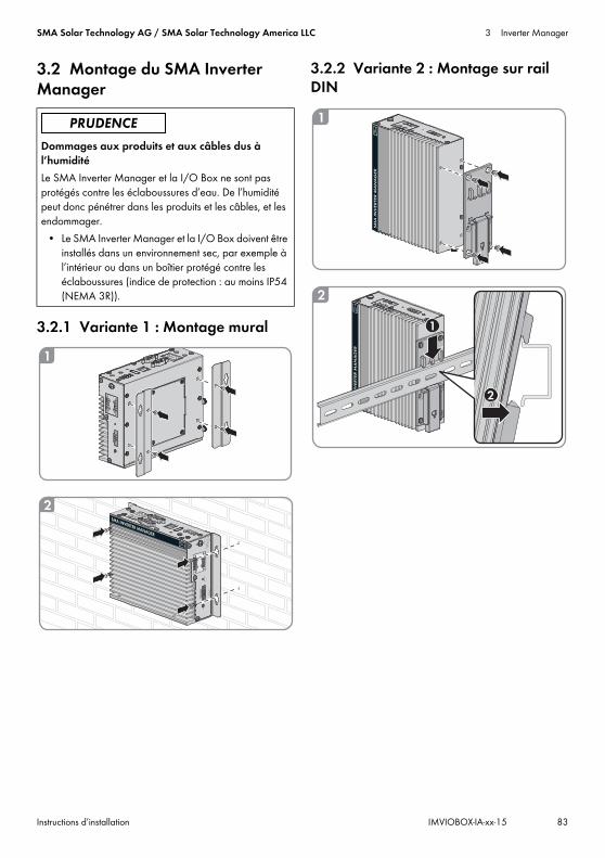
SMA Solar Technology AG / SMA Solar Technology America LLC 3 Inverter Manager
Instructions d’installation IMVIOBOX-IA-xx-15 83
3.2 Montage du SMA Inverter Manager
3.2.1 Variante 1 : Montage mural
3.2.2 Variante 2 : Montage sur rail DIN
Dommages aux produits et aux câbles dus à l’humiditéLe SMA Inverter Manager et la I/O Box ne sont pas protégés contre les éclaboussures d’eau. De l’humidité peut donc pénétrer dans les produits et les câbles, et les endommager.
• Le SMA Inverter Manager et la I/O Box doivent être installés dans un environnement sec, par exemple à l’intérieur ou dans un boîtier protégé contre les éclaboussures (indice de protection : au moins IP54 (NEMA 3R)).

3 Inverter Manager SMA Solar Technology AG / SMA Solar Technology America LLC
84 IMVIOBOX-IA-xx-15 Instructions d’installation
3.3 Raccordement au SMA Inverter Manager3.3.1 Consigne de sécurité
3.3.2 Vue d’ensemble du câblage
Figure 2: Vue d’ensemble du câblage
Danger de mort par choc électriqueDes tensions mortelles sont présentes au point de raccordement du réseau électrique public.
• Mettez le point de raccordement hors tension et vérifiez qu’il est bien hors tension.
Position DésignationA OnduleurB Ordinateur avec LCS-ToolC Routeur
D Station météorologique compatible Sunspec Alliance (en option)
E I/O Box (en option)F Inverter Manager
Position Désignation

SMA Solar Technology AG / SMA Solar Technology America LLC 3 Inverter Manager
Instructions d’installation IMVIOBOX-IA-xx-15 85
3.3.3 Raccordement de l’onduleur et du routeur via EthernetAffectation des broches sur les prises réseau (LAN 1 et LAN 2) :
Figure 3: Affectation des broches sur les prises réseau
3.3.4 Raccordement de la I/O Box et de la station météorologique (en option)
Affectation des broches de l’interface série (RS485), côté SMA Inverter Manager :
Figure 4: Affectation des broches de l'interface sérielle
La I/O Box est connectée au port 2 du SMA Inverter Manager. Une terminaison pour l’interface RS485 n’est pas nécessaire.
Interfaces et données de la station météorologiqueUne seule station météorologique peut être connectée à chaque SMA Inverter Manager. La station météorologique est connectée au port 1 du SMA Inverter Manager. 2 capteurs de température au maximum sont autorisés.Les données suivantes de la station météorologique sont mises à disposition par le SMA Inverter Manager :
Broche Affectation pour 10/100 Mbps
Affectation pour 1000 Mbps
1 ETx+ TRD(0)+2 ETx- TRD(0)-3 ERx+ TRD(1)+4 --- TRD(2)+5 --- TRD(2)-6 ERx- TRD(1)-7 --- TRD(3)+8 --- TRD(3)-
Ne pas effectuer le raccordement en cours de fonctionnementNe raccordez pas la I/O Box ou la station météorologique au SMA Inverter Manager en cours de fonctionnement. Des erreurs qui ne seront pas détectées tout de suite peuvent se produire.
• Mettez le SMA Inverter Manager hors tension.
8 1
81
Broche Affectation1 ---2 ---3 DataB(+)4 DataA(-)5 GND6 ---7 ---8 ---
Données météorologiques
SunSpec Modbus TCP
LCS-Tool/FTP-Push
Sunny Portal
Température ambiante et température des panneaux photovoltaïques
oui oui oui
Direction et vitesse du vent
oui oui oui
321 4 5
9876

3 Inverter Manager SMA Solar Technology AG / SMA Solar Technology America LLC
86 IMVIOBOX-IA-xx-15 Instructions d’installation
3.3.5 Raccordement du SMA Inverter Manager à l’alimentation en tension
Procédure :Pour raccorder le SMA Inverter Manager à l’alimentation en tension, effectuez les manipulations suivantes dans l’ordre donné.
• Raccordez le conducteur de protection au SMA Inverter Manager.
• Raccordez le bloc d’alimentation.
Raccordement du conducteur de protection au SMA Inverter ManagerSG : Le contact de mise à la terre protégée (Shielded Ground, SG ; également appelé « Protected Ground ») se trouve, dans la vue représentée, en haut au niveau de l’embase pour le raccordement électrique.Procédure :
• Mettez le SMA Inverter Manager à la terre. Pour ce faire, raccordez le conducteur de protection à la vis de mise à la terre du SMA Inverter Manager. Une mise à la terre et une pose des câbles dans les règles de l’art contribuent à restreindre de possibles émissions parasites liées à des interférences électromagnétiques (IEM).
Raccordement du bloc d’alimentation
SMA recommande d’utiliser le bloc d’alimentation pour rail DIN disponible en accessoire (numéro de commande : CLCON-PWRSUPPLY)* .Procédure :
1. Montez le bloc d’alimentation (voir instructions du fabricant).
2. Raccordez le câble de raccordement au bloc d’alimentation (voir instructions du fabricant). Raccourcissez pour ce faire les conducteurs non utilisés jusqu’à la gaine du câble et notez leur couleur.
3. Raccordez le câble de raccordement à la plaque à bornes d’alimentation en tension (9 Vdc à 36 Vdc). Assurez-vous que le conducteur de terre blindé est relié à la borne de terre.
4. Insérez la plaque à bornes de l’alimentation en tension avec le bloc d’alimentation raccordé dans l’embase « Power Input » du SMA Inverter Manager.
5. Branchez le câble de raccordement AC au bloc d’alimentation (voir instructions du fabricant).
7. Raccordez l’autre extrémité du câble de raccordement AC à l’alimentation en tension.
8. Connectez le point de raccordement au réseau électrique public.
☑ Dès que la DEL Power s’allume en vert, cela signifie que le SMA Inverter Manager est opérationnel.
Rayonnement horizontal
oui oui non disponible en cas de rayonnement incliné
Rayonnement incliné
non oui oui
Danger de mort par choc électrique au contact d’un produit non mis à la terre Le contact avec un produit non mis à la terre peut provoquer un choc électrique susceptible d’entraîner la mort.
• Assurez-vous que le produit est intégré dans la protection contre les surtensions existante.
• Mettez à la terre le boîtier du produit.
Données météorologiques
SunSpec Modbus TCP
LCS-Tool/FTP-Push
Sunny Portal
* Non disponible dans tous les pays.
6.Danger de mort par choc électriqueDes tensions mortelles sont présentes au point de raccordement du réseau électrique public.
• Mettez hors tension le point de raccordement et sécurisez-le contre toute remise en marche.
GND9 to 36 VDC

SMA Solar Technology AG / SMA Solar Technology America LLC 3 Inverter Manager
Instructions d’installation IMVIOBOX-IA-xx-15 87
3.4 Connexion Ethernet du SMA Inverter ManagerLAN 1 (réseau de l’installation)L’adresse IP et le masque de sous-réseau sont attribués au port LAN 1 du SMA Inverter Manager par un serveur DHCP externe. Il est aussi possible d’attribuer de façon manuelle une adresse IP au port LAN 1 du SMA Inverter Manager.
LAN 2 (réseau des onduleurs)L’adresse IP est attribuée à l’onduleur par le SMA Inverter Manager.
Réinitialisation du Inverter Manager sur DHCP• Pour réinitialiser le Inverter Manager sur DHCP,
appuyez trois fois sur la touche [Power] en l'espace d'une seconde.
3.5 Signaux de la DEL du SMA Inverter Manager
3.6 Caractéristiques techniques
DEL État ExplicationPower allumée en
vertLe SMA Inverter Manager est en service.
éteinte Le SMA Inverter Manager n’est pas en service.
LAN allumée en vert
Mode Ethernet 100 Mbps
allumée en jaune
Mode Ethernet 1000 Mbps (Gigabit)
éteinte Aucune activité ou Ethernet 10 Mbps
Tx1, Tx2 (P1-P2)
clignote en vert
Transmission de données via ports série P1-P2
éteinte Aucune transmission de données via ports série P1-P2
Rx1, Rx2 (P1-P2)
clignote en vert
Réception de données via ports série P1-P2
éteinte Aucune réception de données via ports série P1-P2
Alimentation en tensionTension d’entrée 9 à 36 VDCPuissance consommée < 20 WSection maximale de conducteur
1,3 mm² (16 AWG)
Caractéristiques généralesDimensions (largeur x hauteur x profondeur)
160 mm x 125 mm x 49 mm
(6,3 in x 4,9 in x 1,9 in)Poids 940 g (2 lbs)Type de montage Montage mural ou sur rail
DINPlage de température de fonctionnement
-40 °C à +75 °C (-40 °F à +167 °F)
Humidité relative de l’air (sans condensation)
5 % à 95 %
Homologations UL 508, UL 60950-1, CSA C22.2 No.
60950-1-07, EN 60950-1, CCC (GB9254,
GB17625.1), EN 55022, Class A, EN 61000-3-2, Class D, EN 61000-3-3, EN 55024, FCC Part 15,
Subpart B, Class A
InterfacesInterface utilisateur LCS-Tool pour PC via
EthernetInterface vers l’onduleur LAN 2, interface Ethernet
(RJ45)Interface vers le réseau externe
LAN 1, interface Ethernet (RJ45)
Interface vers la I/O Box (en option)
RS485 (D-Sub 9) / Mode SunSpec
Interface capteurs pour stations météorologiques compatibles Sunspec (en option)
RS485 (D-Sub 9) / Mode SunSpec
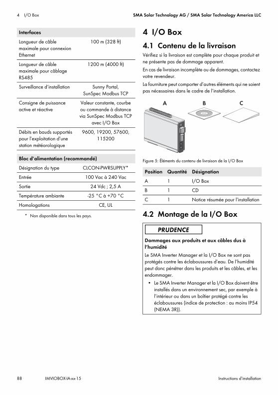
4 I/O Box SMA Solar Technology AG / SMA Solar Technology America LLC
88 IMVIOBOX-IA-xx-15 Instructions d’installation
4 I/O Box4.1 Contenu de la livraisonVérifiez si la livraison est complète pour chaque produit et ne présente pas de dommage apparent.En cas de livraison incomplète ou de dommages, contactez votre revendeur.La fourniture peut comporter d’autres éléments qui ne soient pas nécessaires dans le cadre de l’installation.
Figure 5: Éléments du contenu de livraison de la I/O Box
4.2 Montage de la I/O Box
Longueur de câble maximale pour connexion Ethernet
100 m (328 ft)
Longueur de câble maximale pour câblage RS485
1200 m (4000 ft)
Surveillance d’installation Sunny Portal, SunSpec Modbus TCP
Consigne de puissance active et réactive
Valeur constante, courbe ou commande à distance via SunSpec Modbus TCP
avec I/O BoxDébits en bauds supportés pour l’exploitation d’une station météorologique
9600, 19200, 57600, 115200
Bloc d’alimentation (recommandé)Désignation du type CLCON-PWRSUPPLY*Entrée 100 Vac à 240 VacSortie 24 Vdc ; 2,5 ATempérature ambiante -25 °C à +70 °CHomologations CE, UL
* Non disponible dans tous les pays.
Interfaces
Position Quantité DésignationA 1 I/O BoxB 1 CDC 1 Notice résumée pour l’installation
Dommages aux produits et aux câbles dus à l’humiditéLe SMA Inverter Manager et la I/O Box ne sont pas protégés contre les éclaboussures d’eau. De l’humidité peut donc pénétrer dans les produits et les câbles, et les endommager.
• Le SMA Inverter Manager et la I/O Box doivent être installés dans un environnement sec, par exemple à l’intérieur ou dans un boîtier protégé contre les éclaboussures (indice de protection : au moins IP54 (NEMA 3R)).
A B C
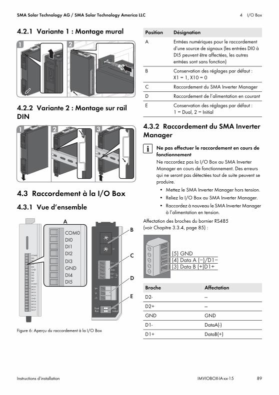
SMA Solar Technology AG / SMA Solar Technology America LLC 4 I/O Box
Instructions d’installation IMVIOBOX-IA-xx-15 89
4.2.1 Variante 1 : Montage mural
4.2.2 Variante 2 : Montage sur rail DIN
4.3 Raccordement à la I/O Box4.3.1 Vue d’ensemble
Figure 6: Aperçu du raccordement à la I/O Box
4.3.2 Raccordement du SMA Inverter Manager
Affectation des broches du bornier RS485 (voir Chapitre 3.3.4, page 85) :
1 2
1 2 3
12
3456
7
8 9 01
2
3456
7
8 9 01
2
3456
7
8 9 01
2
3456
7
8 9 0
D1+
D1-
GND
D2+
D2-
P1
P2
V+
V-
X10
X1
DualRun
RepInitial
COM0
DI0
DI1
DI2
DI3
DI4
DI5
DI6
DI7
COM1
DIO0
DIO1
DIO2
DIO3
GND
DIO4
DIO5
DIO6
DIO7
GND
A
C
D
COM0
DI0
DI1
DI2
DI3
DI4
DI5
GND
B
E
Position DésignationA Entrées numériques pour le raccordement
d’une source de signaux (les entrées DI0 à DI5 peuvent être affectées, les autres entrées sont sans fonction)
B Conservation des réglages par défaut : X1 = 1, X10 = 0
C Raccordement du SMA Inverter ManagerD Raccordement de l’alimentation en courantE Conservation des réglages par défaut :
1 = Dual, 2 = Initial
Ne pas effectuer le raccordement en cours de fonctionnementNe raccordez pas la I/O Box au SMA Inverter Manager en cours de fonctionnement. Des erreurs qui ne seront pas détectées tout de suite peuvent se produire.
• Mettez le SMA Inverter Manager hors tension.• Reliez la I/O Box au SMA Inverter Manager.• Raccordez à nouveau le SMA Inverter Manager
à l’alimentation en tension.
Broche AffectationD2- ---D2+ ---GND GNDD1- DataA(-)D1+ DataB(+)
(5) GND
(3) Data B (+)D1+(4) Data A (−)/D1−

4 I/O Box SMA Solar Technology AG / SMA Solar Technology America LLC
90 IMVIOBOX-IA-xx-15 Instructions d’installation
4.3.3 Raccordement de la source de signauxRaccordement d’une source de signaux avec contact de relais sans potentiel
Raccordement d’une source de signaux (10 à 30 V) avec signaux de sortie numériques
4.3.4 Raccordement de l’I/O Box à l’alimentation en tensionRaccordez le câble de raccordement de 12 Vdc à 36 Vdc à la borne d’alimentation en tension. Raccordez la mise à la terre du câble de raccordement à la borne « V- » et raccordez la broche de mise à la terre si une mise à la terre (GND) est disponible.
4.3.5 Signaux DEL de la I/O Box
4.4 Caractéristiques techniques
Broche AffectationV- / V+ Alimentation en tension 24 Vdc
(12 Vdc à 36 Vdc)
Diamètre des fils de raccordementPour des raisons de sécurité, les fils de raccordement pour l’alimentation électrique doivent avoir un diamètre d’au moins 2 mm².
DEL État ExplicationPower allumée en
jauneLa I/O Box est en service.
éteinte La I/O Box n’est pas en service.Ready allumée en
vertLe système est opérationnel.
clignote en vert 1 fois par seconde
La fonction « Détecter » a été déclenchée.
clignote en vert toutes les 0,5 secondes
Le micrologiciel est en cours de mise à jour.
clignote en vert
Si la DEL verte s’allume pendant 5 secondes et qu’elle s’éteint ensuite pendant 5 secondes, cela veut dire que le système est en « Safe Mode ».
éteinte Le système n’est pas opérationnel.
Port 1 clignote en vert
Des données sont en cours d’émission ou de réception.
Port 2 clignote en jaune
Des données sont en cours d’émission ou de réception.
Données systèmeAlimentation en courant 24 Vdc nominal,
12 Vdc à 36 VdcCâblage Câble I/O max. 25 mm²
(4 AWG)Dimensions 27,8 mm x 124 mm x 84 mm
(1.09 x 4.88 x 3.31 in)Poids < 200 gPlage de température de fonctionnement
Module standard :-10 °C à +75 °C (14 °F à 167 °F)
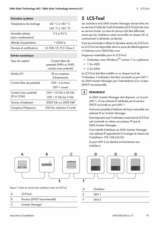
SMA Solar Technology AG / SMA Solar Technology America LLC 5 LCS-Tool
Instructions d’installation IMVIOBOX-IA-xx-15 91
5 LCS-ToolLes onduleurs et le SMA Inverter Manager doivent être mis en service à l’aide de l’outil d’entretien (LCS-Tool) et de mise en service locale. La mise en service doit être effectuée avant que les onduleurs soient raccordés au réseau AC et commencent à alimenter ce dernier. Il est recommandé s’utiliser la dernière version du LCS-Tool. Le LCS-Tool est disponible dans la zone de téléchargement à l’adresse www.SMA-Solar.com.Exigences matérielles pour le LCS-Tool :
• Ordinateur avec WindowsTM version 7 ou supérieure• 1 Go HDD• 2 Go RAM
Le LCS-Tool doit être installé sur un disque local de l’ordinateur. L’ordinateur doit être connecté au port LAN 1 du SMA Inverter Manager par l’intermédiaire d’un routeur (DHCP recommandé).
Figure 7: Mise en service des onduleurs avec le LCS-Tool
Température de stockage -40 °C à +85 °C(-40 °F à 185 °F)
Humidité relative (sans condensation)
5 % à 95 %
Altitude d’exploitation < 2000 mNormes et certifications UL 508, CE, FCC Class A
Entrée numériqueType de capteur Contact libre de
potentiel (NPN ou PNP), contact avec potentiel
Mode I/O DI ou compteur d’événements
Contact libre de potentiel ON = à la terreOFF = ouvert
Contact avec potentiel (DI à COM)
ON = 10 Vdc à 30 VdcOFF = 0 Vdc bis 3 Vdc
Tension d’isolement 3000 Vdc ou 2000 VeffCompteur/Fréquence 250 Hz, mémoire à l’arrêt
Données système
REMARQUELe SMA Inverter Manager doit disposer, sur le port LAN 1, d’une adresse IP attribuée par le serveur DHCP raccordé au port LAN 1.Il est aussi possible d’attribuer de façon manuelle une adresse IP au Inverter Manager.Il est important que l’ordinateur exécutant le LCS-Tool soit connecté au même sous-réseau IP que le SMA Inverter Manager. Il est interdit d’attribuer au SMA Inverter Manager une adresse IP appartenant à la plage du réseau de l’installation 192.168.4.0/24.Le port LAN 2 est destiné exclusivement aux onduleurs.
A LCS-ToolB Routeur (DHCP recommandé)C Inverter Manager
D OnduleurE LAN 1F LAN 2
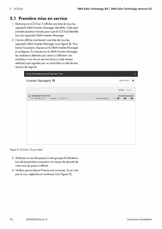
5 LCS-Tool SMA Solar Technology AG / SMA Solar Technology America LLC
92 IMVIOBOX-IA-xx-15 Instructions d’installation
5.1 Première mise en service1. Démarrez le LCS-Tool. Il affiche une liste de tous les
appareils SMA Inverter Manager identifiés. Cela peut prendre plusieurs minutes pour que le LCS-Tool identifie tous les appareils SMA Inverter Manager.
2. L’écran affiche maintenant une liste de tous les appareils SMA Inverter Manager (voir figure 8). Pour lancer l’assistant, cliquez sur le SMA Inverter Manager à configurer. En cliquant sur le SMA Inverter Manager, les onduleurs détectés par celui-ci s’affichent. Les onduleurs non mis en service (aucun code réseau attribué) sont signalés par un carré bleu à côté de leur version de logiciel.
Figure 8: LCS-Tool - Écran initial
3. Attribuez un mot de passe à votre groupe d’utilisateurs lors de la première connexion. Le niveau de sécurité de votre mot de passe s’affiche.
4. Vérifiez que la date et l’heure sont correctes. Si ce n’est pas le cas, réglez-les et continuez (voir figure 9).

SMA Solar Technology AG / SMA Solar Technology America LLC 5 LCS-Tool
Instructions d’installation IMVIOBOX-IA-xx-15 93
Figure 9: LCS-Tool - Vérification de la date et de l’heure
5. En option, vous pouvez attribuer un nom, un site et un titulaire au SMA Inverter Manager (voir figure 10).
Figure 10: LCS-Tool - Détails de l’installation
6. Une liste des onduleurs identifiés par le SMA Inverter Manager sélectionné apparaît (voir figure 11).
Vérifiez que tous les onduleurs sont présents. Il est possible de continuer la configuration des onduleurs répertoriés même si les onduleurs ne sont pas tous détectés. Les onduleurs non détectés pourront être configurés ultérieurement.

5 LCS-Tool SMA Solar Technology AG / SMA Solar Technology America LLC
94 IMVIOBOX-IA-xx-15 Instructions d’installation
Figure 11: LCS-Tool - Liste des onduleurs connectés
7. Sélectionnez le pays souhaité dans la liste des options disponibles pour les onduleurs du réseau (voir figure 12).
8. Sélectionnez le code réseau souhaité parmi la liste d’options disponibles pour le pays sélectionné. Si nécessaire, chargez un code réseau personnalisé en cliquant sur le bouton [Load] (voir figure 12). Le bouton [Create] est inactif et ne peut pas être utilisé.
Figure 12: LCS-Tool - Sélection du pays et du code réseau

SMA Solar Technology AG / SMA Solar Technology America LLC 5 LCS-Tool
Instructions d’installation IMVIOBOX-IA-xx-15 95
9. Le LCS-Tool invite à confirmer le pays et le code réseau sélectionnés (voir figure 13). Une configuration incorrecte peut être modifiée à l’aide du bouton [Back] et en changeant les réglages dans les fenêtres précédentes.
Figure 13: LCS-Tool - Vérification du pays et du code réseau
10. Le système applique maintenant le code réseau sélectionné au SMA Inverter Manager et aux onduleurs détectés. Tout onduleur ajouté ultérieurement reçoit automatiquement le même code réseau. Un seul code réseau est autorisé par SMA Inverter Manager.
11. Un carré vert identifie les onduleurs mis en service. Cependant, les onduleurs ne se connectent pas au réseau tant que l’ordre de démarrage [Start] n’a pas été émis dans la barre située en dessous du menu de démarrage (voir figure 14).
REMARQUEIl est essentiel de choisir le code réseau qui convient. Une modification du code réseau après les 10 premières heures de service n’est possible qu’à l’aide d’un code Grid Guard personnel.Les paramètres du code réseau peuvent être modifiés après-coup dans le LCS-Tool (voir chapitre 5.2.6, page 104). Ceci n’est possible que si c’est la dernière version du LCS-Tool qui est utilisée.

5 LCS-Tool SMA Solar Technology AG / SMA Solar Technology America LLC
96 IMVIOBOX-IA-xx-15 Instructions d’installation
Figure 14: LCS-Tool - Liste de tous les onduleurs connectés au SMA Inverter Manager
12. Si la puissance photovoltaïque disponible est suffisante et si les conditions de code réseau sont remplies, l’onduleur commence à fonctionner.
13. Lors de la mise en service, il est possible de télécharger un rapport de mise en service dans le menu « Reports ». Le rapport contient toutes les informations concernant les réglages des onduleurs, y compris les valeurs de déconnexion définies pour chaque onduleur. Le symbole Classeur, dans le menu Reports, permet d’ouvrir un répertoire des rapports de mise en service (y compris les informations de code réseau) (voir figure 15).
Figure 15: LCS-Tool - Rapport de mise en service

SMA Solar Technology AG / SMA Solar Technology America LLC 5 LCS-Tool
Instructions d’installation IMVIOBOX-IA-xx-15 97
5.2 Fonctionnement5.2.1 Mot de passe oublié
Figure 16: LCS-Tool - Mot de passe oublié
Si vous avez oublié le mot de passe de l’interface utilisateur, vous pouvez vous connecter à l’aide d’un code PUK (Personal Unlocking Key). Il existe un code PUK pour chaque groupe d’utilisateurs.
Procédure :1. Demandez le PUK (voir « Demande d’un code PUK »
sur www.SMA-Solar.com).2. Ouvrez le LCS-Tool.3. Sélectionnez le groupe d’utilisateurs User ou
Installer.4. Entrez le PUK à la place du mot de passe.5. Appelez le menu Setup.6. Sous Password, modifiez le mot de passe pour le
groupe d’utilisateurs souhaité.7. Cliquez sur [Save] pour sauvegarder les
modifications.

5 LCS-Tool SMA Solar Technology AG / SMA Solar Technology America LLC
98 IMVIOBOX-IA-xx-15 Instructions d’installation
5.2.2 Modification du code réseau
Figure 17: LCS-Tool - Saisie du code SMA Grid Guard
Pour réinitialiser le SMA Inverter Manager au bout des 10 premières heures de service et sélectionner un nouveau jeu de données régionales, utilisez votre code Grid Guard dans le groupe d’utilisateurs Installer (voir certificat « Formulaire de commande du code Grid Guard » sur www.SMA-Solar.com).
Procédure :1. Ouvrez le LCS-Tool.2. Connectez-vous en tant que Installer.3. Appelez le menu Service.4. Dans le champ Individual access code, sous Grid
Guard, entrez votre code Grid Guard personnel.5. Cliquez sur [Save] pour sauvegarder les
modifications.☑ Un nouveau point de menu General est
disponible dans le menu Setup.

SMA Solar Technology AG / SMA Solar Technology America LLC 5 LCS-Tool
Instructions d’installation IMVIOBOX-IA-xx-15 99
5.2.3 Mise à jour du micrologiciel
Figure 18: LCS-Tool - Mise à jour manuelle du micrologiciel
Vous pouvez mettre à jour le micrologiciel du SMA Inverter Manager manuellement. Il est recommandé s’utiliser la dernière version du LCS-Tool. Le LCS-Tool est disponible dans la zone de téléchargement à l’adresse www.SMA-Solar.com.
Procédure :1. Ouvrez le LCS-Tool.2. Connectez-vous en tant que User ou Installer.3. Appelez le menu Service.4. Sous Software Update, sélectionnez l’onglet
Inverter manager.5. Pour exécuter la mise à jour, sélectionnez
[Start update]. ☑ La mise à jour est maintenant exécutée.
Dommages sur les produits à la suite de l’interruption de la procédure de mise à jourToute interruption de la liaison entre le SMA Inverter Manager et l’ordinateur peut entraîner des dommages sur l’appareil.
• Ne coupez pas la liaison entre le SMA Inverter Manager et l’ordinateur.
• Ne coupez pas la tension secteur du SMA Inverter Manager ni de l’ordinateur.
• Ne faites pas passer l’ordinateur en mode économie d’énergie.

5 LCS-Tool SMA Solar Technology AG / SMA Solar Technology America LLC
100 IMVIOBOX-IA-xx-15 Instructions d’installation
5.2.4 Paramètres de secours de l’installation
Figure 19: LCS-Tool - Réglage des paramètres de secours
Pour le cas où la communication serait interrompue entre le SMA Inverter Manager et une unité de régulation hiérarchiquement supérieure (par exemple un système SCADA ou un contrôleur de centrale), il est possible de définir une configuration de secours. Cette configuration peut être effectuée uniquement par l’intermédiaire du LCS-Tool. Afin de définir les paramètres de la configuration de secours, utilisez votre code Grid Guard personnel dans le groupe utilisateurs Installer (voir chapitre 5.2.2, page 98).
Procédure :1. Ouvrez le LCS-Tool.2. Connectez-vous en tant que Installer.3. Appelez le menu Setup.4. Saisissez les valeurs correspondantes au point
Plant fallback.5. Cliquez sur [Save] pour sauvegarder les
modifications.
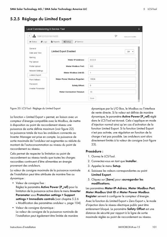
SMA Solar Technology AG / SMA Solar Technology America LLC 5 LCS-Tool
Instructions d’installation IMVIOBOX-IA-xx-15 101
5.2.5 Réglage du Limited Export
Figure 20: LCS-Tool - Réglage du Limited Export
La fonction « Limited Export » permet, en liaison avec un compteur d’énergie compatible avec le Modbus, de mettre à disposition au point de raccordement réseau une puissance de sortie définie maximum (voir figure 22). La puissance totale de tous les onduleurs connectés au Inverter Manager est prise en compte. La puissance de sortie maximale de l’onduleur est augmentée ou réduite du montant de l’autoconsommation au niveau du point de raccordement au réseau. Cela permet de respecter la limitation au point de raccordement au réseau tandis que toutes les charges raccordées continuent d’être alimentées en énergie provenant des onduleurs.La valeur de consigne maximale de la puissance nominale de l’installation peut être attribuée de manière fixe ou dynamique :
• Valeur de consigne fixe : Réglez le paramètre Active Power (P_ref) pour la limitation de la puissance active dans le menu Inverter Parameter sous Protection settings > Support settings > Immediate controls (voir chapitre 5.2.6 « Modification des paramètres onduleur », page 104).
• Valeur de consigne dynamique : La valeur de consigne de la puissance nominale de l’installation peut également être limitée de manière
dynamique par la I/O Box, le Modbus ou l’interface de vente directe. Si la valeur est définie de manière dynamique, le paramètre Active Power (P_ref) réglé dans le LCS-Tool est écrasé. Cela s’applique en mode d’injection normal ainsi qu’en cas d’activation de la fonction Limited Export. Si la fonction Limited Export n’est pas activée, une régulation en fonction de la charge n’est pas possible. Les onduleurs sont alors directement limités à la valeur de consigne (voir figure 23).
Procédure :1. Ouvrez le LCS-Tool.2. Connectez-vous en tant que Installer.3. Appelez le menu Setup.4. Saisissez les valeurs correspondantes au point
Limited Export.5. Cliquez sur [Save] pour sauvegarder les
modifications.Les paramètres Meter-IP--Adress, Meter Modbus Port, Meter Modbus Unit ID et Meter Power Modbus Register servent à configurer le compteur d’énergie. Avec la fonction du Limited Export « Zero Export », le mode d’injection dans le réseau électrique public peut être entièrement bloqué. Le paramètre Safety Offset est une distance de sécurité par rapport à la ligne de sortie maximale réglée au point de raccordement au réseau.

5 LCS-Tool SMA Solar Technology AG / SMA Solar Technology America LLC
102 IMVIOBOX-IA-xx-15 Instructions d’installation
Elle est indiquée en % de la puissance nominale de l’installation. Cette distance de sécurité, qui définit l’écart par rapport à la valeur de consigne, est attribuée pour des raisons de sécurité et pour compenser les sauts de charge soudains. En cas d’activation, la valeur de consigne est réduite de la valeur de sécurité. La puissance injectée est ainsi toujours inférieure à la valeur de consigne réelle.Le paramètre Meter Connection Timeout correspond au temps en secondes au bout duquel la puissance nominale de l’installation est réglée sur 0 W après une interruption de la communication.Pour avoir un aperçu des valeurs actuelles de l’installation, appelez le menu Status et sélectionnez Overview (voir figure 21).
Figure 21: LCS-Tool - Aperçu des valeurs actuelles de l’installation
Régulation via ModbusPour régler une limitation durable, définissez la valeur souhaitée dans le registre Modbus 40349.Pour déconnecter immédiatement l’onduleur du réseau électrique public en dépit de l’activation de la fonction Limited Export, réglez la valeur « 0 » dans le registre Modbus 40348.Pour plus d’informations sur l’interface Modbus, voir l’information technique « SUNNY TRIPOWER 60 / SUNNY HIGHPOWER PEAK1 - SunSpec® Modbus® Interface » sur www.SMA-Solar.com.

SMA Solar Technology AG / SMA Solar Technology America LLC 5 LCS-Tool
Instructions d’installation IMVIOBOX-IA-xx-15 103
Figure 22: Mode d’injection avec « Limited Export »
Figure 23: Mode d’injection sans « Limited Export »
A OnduleurB Inverter ManagerC Appareils consommateursD Réseau électrique publicE Point de raccordement au réseauF Modbus TCPG AC
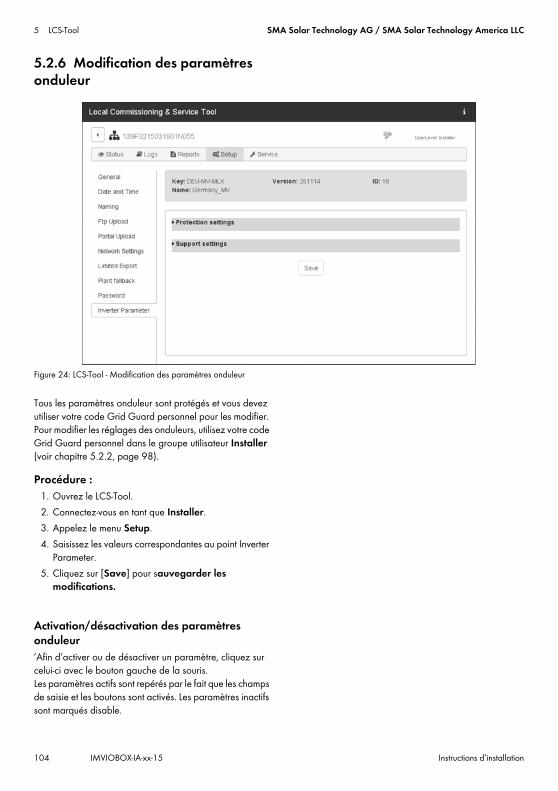
5 LCS-Tool SMA Solar Technology AG / SMA Solar Technology America LLC
104 IMVIOBOX-IA-xx-15 Instructions d’installation
5.2.6 Modification des paramètres onduleur
Figure 24: LCS-Tool - Modification des paramètres onduleur
Tous les paramètres onduleur sont protégés et vous devez utiliser votre code Grid Guard personnel pour les modifier. Pour modifier les réglages des onduleurs, utilisez votre code Grid Guard personnel dans le groupe utilisateur Installer (voir chapitre 5.2.2, page 98).
Procédure :1. Ouvrez le LCS-Tool.2. Connectez-vous en tant que Installer.3. Appelez le menu Setup.4. Saisissez les valeurs correspondantes au point Inverter
Parameter.5. Cliquez sur [Save] pour sauvegarder les
modifications.
Activation/désactivation des paramètres onduleur’Afin d’activer ou de désactiver un paramètre, cliquez sur celui-ci avec le bouton gauche de la souris. Les paramètres actifs sont repérés par le fait que les champs de saisie et les boutons sont activés. Les paramètres inactifs sont marqués disable.

SMA Solar Technology AG / SMA Solar Technology America LLC 5 LCS-Tool
Instructions d’installation IMVIOBOX-IA-xx-15 105
Figure 25: LCS-Tool - Activation/désactivation des paramètres onduleur
Changement du signe dans les paramètres du facteur de puissancePour changer le signe des paramètres du facteur de puissance, cliquer sur le signe avec le bouton gauche de la souris.
Figure 26: LCS-Tool - Changement du signe

5 LCS-Tool SMA Solar Technology AG / SMA Solar Technology America LLC
106 IMVIOBOX-IA-xx-15 Instructions d’installation
Réglage des paramètres de la I/O BoxAfin de saisir les paramètres dans le sous-menu I/O Box, cliquez dans les champs de saisie avec le bouton droit de la souris.
Figure 27: LCS-Tool - Réglage des paramètres de la I/O Box
5.2.7 LogsDans le menu Logs, vous pouvez appeler des informations sur les événements, les données sur la puissance, les paramétrages et les paramètres onduleurs ayant été modifiés.
Figure 28: LCS-Tool - Logs

IMVIOBOX-IA-xx-15 | Version 1.5 日本語
1 本書について1.1 適用範囲本書に記載されている情報は、SMA Inverter Manager、SMA Digital I/O Box、LCS ツールに当てはまります。
1.2 対象読者本書で説明している作業は、必ず適切な資格を持っている方だけが行ってください。設置担当者に必要な条件は次の通りです。
• 電気機器の設置および起動に関する訓練を受けていること
• 電気機器類や設備の設置や使用に伴う危険への対応について訓練を受けていること
• IT システムの設置と設定に関する訓練を受けていること
• パワーコンディショナの仕組みや操作方法に関する知識を持っていること
• 適用されるすべての法律と規格に関する知識を持っていること
• 本書の内容、安全上の注意と警告メッセージをすべて理解し、これに従うこと
1.3 本書で使用する記号
1.4 製品の表記について
アイコン/マーク 説明
「危険」は、回避しなければ死亡または重傷を招く危険な状況を示します。
「警告」は、回避しなければ死亡または重傷を招く恐れがある危険な状況を示します。
「注意」は、回避しなければ軽傷または中度の怪我を招く恐れがある危険な状況を示します。
「注記」は、回避しなければ物的損害を招く恐れがある状況を示します。
特定のテーマや目的にとって重要ですが、安全性には関係のない情報を示します。
☐ 特定の目的を達成するために、必要な条件を示します。
☑ 期待される結果を示します。
✖ 起こり得る問題を示します。
正式名称 本書での表記
SMA Inverter Manager Inverter Manager
SMA Digital I/O Box I/O Box
Local commissioning and service tool(現地での試運転調整とサービスツール、LCS ツール)
LCS ツール
SMA Solar Technology AG SMA
SMA Solar Technology America LLC
SMA Solar Technology Canada Inc.
アイコン/マーク 説明
設置説明書SMA INVERTER MANAGER / SMA DIGITAL I/O BOX / LCS-TOOL
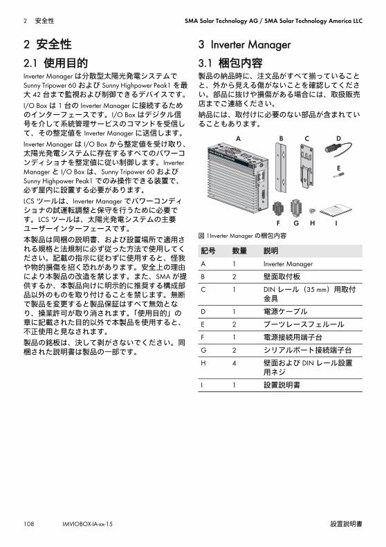
2 安全性 SMA Solar Technology AG / SMA Solar Technology America LLC
108 IMVIOBOX-IA-xx-15 設置説明書
2 安全性2.1 使用目的Inverter Manager は分散型太陽光発電システムでSunny Tripower 60 および Sunny Highpower Peak1 を大 42 台まで監視および制御できるデバイスです。I/O Box は 1 台の Inverter Manager に接続するためのインターフェースです。I/O Box はデジタル信号を介して系統管理サービスのコマンドを受信して、その整定値を Inverter Manager に送信します。Inverter Manager は I/O Box から整定値を受け取り、太陽光発電システムに存在するすべてのパワーコンディショナを整定値に従い制御します。Inverter Manager と I/O Box は、Sunny Tripower 60 およびSunny Highpower Peak1 でのみ操作できる装置で、必ず屋内に設置する必要があります。LCS ツールは、Inverter Manager でパワーコンディショナの試運転調整と保守を行うために必要です。LCS ツールは、太陽光発電システムの主要ユーザーインターフェースです。本製品は同梱の説明書、および設置場所で適用される規格と法規制に必ず従った方法で使用してください。記載の指示に従わずに使用すると、怪我や物的損傷を招く恐れがあります。安全上の理由により本製品の改造を禁じます。また、SMA が提供するか、本製品向けに明示的に推奨する構成部品以外のものを取り付けることを禁じます。無断で製品を変更すると製品保証はすべて無効となり、操業許可が取り消されます。「使用目的」の章に記載された目的以外で本製品を使用すると、不正使用と見なされます。 製品の銘板は、決して剥がさないでください。同梱された説明書は製品の一部です。
3 Inverter Manager3.1 梱包内容製品の納品時に、注文品がすべて揃っていることと、外から見える傷がないことを確認してください。部品に抜けや損傷がある場合には、取扱販売店までご連絡ください。納品には、取付けに必要のない部品が含まれていることもあります。
図 1Inverter Manager の梱包内容
記号 数量 説明
A 1 Inverter Manager
B 2 壁面取付板
C 1 DIN レール(35 mm)用取付金具
D 1 電源ケーブル
E 2 ブーツレースフェルール
F 1 電源接続用端子台
G 2 シリアルポート接続端子台
H 4 壁面および DIN レール設置用ネジ
I 1 設置説明書

SMA Solar Technology AG / SMA Solar Technology America LLC 3 Inverter Manager
設置説明書 IMVIOBOX-IA-xx-15 109
3.2 Inverter Manager の取り付け
3.2.1 方法 1:壁面に取り付ける
3.2.2 方法 2:DIN レールに取り付ける
水分の浸入による本体とケーブルの損傷Inverter Manager と I/O Box は防水加工されていません。そのため、水分が浸入して本体とケーブルが損傷する可能性があります。
• Inverter Manager と I/O Box は必ず屋内の湿り気のない場所か、少なくとも保護等級 IP54
(NEMA 3R)を満たす防水加工された筐体内に設置してください。
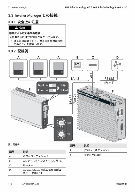
3 Inverter Manager SMA Solar Technology AG / SMA Solar Technology America LLC
110 IMVIOBOX-IA-xx-15 設置説明書
3.3 Inverter Manager との接続
3.3.1 安全上の注意
3.3.2 配線例
図 2 配線例
感電による致死事故の危険系統連系点には致死電圧がかかっています。
• 連系点の電源を切り、連系点が無通電状態であることを確認します。
記号 説明
A パワーコンディショナ
B LCS ツールをインストールした PC
C ルーター
D SunSpec Alliance 対応の気象観測ユニット(別売り)
E I/O Box(オプション)
F Inverter Manager
記号 説明

SMA Solar Technology AG / SMA Solar Technology America LLC 3 Inverter Manager
設置説明書 IMVIOBOX-IA-xx-15 111
3.3.3 パワーコンディショナとルーターのイーサネット接続ネットワークポート(LAN 1 と LAN 2)のピンの割り当て:
図 3 ネットワークポートのピンの割り当て
3.3.4 I/O Box と気象観測ユニットの接続(別売り)
Inverter Manager のシリアルインターフェース(RS485)のピン配列:
図 4 シリアルインターフェースのピン配列
I/O Box は、Inverter Manager の Port 2 に接続する必要があります。RS485 インターフェースに終端接続する必要はありません。
気象観測ユニットのインターフェースと気象データInverter Manager 1 台あたり1台の気象観測ユニットのみを接続できます。気象観測ユニットは、Inverter Manager の Port 1 に接続する必要があります。温度センサーは 2 台まで使用できます。Inverter Manager をお使いの場合に、気象観測ユニットから取得できるデータは次のとおりです。
接続ピン
10/100 Mbps 接続用
1000 Mbps 接続用
1 ETx+ TRD(0)+
2 ETx- TRD(0)-
3 ERx+ TRD(1)+
4 --- TRD(2)+
5 --- TRD(2)-
6 ERx- TRD(1)-
7 --- TRD(3)+
8 --- TRD(3)-
運転中の接続禁止
Inverter Manager の運転中に I/O Box や気象観測ユニットを接続しないでください。エラーが発生してもすぐに検出できない可能性があります。
• Inverter Manager の電源を切ります。
8 1
81
321 4 5
9876
接続ピン 割り当て
1 ---
2 ---
3 DataB(+)
4 DataA(-)
5 GND
6 ---
7 ---
8 ---
気象データ SunSpec Modbus TCP
LCS ツール / FTPプッシュ
Sunny Portal
周囲温度と太陽電池モジュールの温度
〇 〇 〇
風速と風向 〇 〇 〇
水平面日射量 〇 〇 傾斜面日射量のデータがない場合
傾斜面日射量 ー 〇 〇

3 Inverter Manager SMA Solar Technology AG / SMA Solar Technology America LLC
112 IMVIOBOX-IA-xx-15 設置説明書
3.3.5 Inverter Manager と電源の接続
手順:Inverter Manager を電源に接続するには、次の操作を記載の順序で行います。
• 接地線を Inverter Manager に接続します。• 電源ユニットを接続します。
接地線を Inverter Manager に接続する保護接地線(アース線)の接続端子は、下の図の電源接続用コネクタのピンにあります。
手順:• Inverter Manager を接地します。このためには、
Inverter Manager の接地端子ネジに接地線を接続します。接地線を正しく配線することにより、電磁干渉(EMI)を抑えます。
電源ユニットの接続
DIN レール装着式電源ユニットを使用することをお勧めします。この電源ユニットは、アクセサリ
(製品番号:CLCON-PWRSUPPLY*)としてご注文いただけます。
手順:1. 電源ユニットを取り付けます(メーカーの説
明書を参照)。
2. 接続ケーブルを電源ユニットに接続します(メーカーの説明書を参照)。使用しない絶縁
導線をケーブルシースまで切り取り、導線の色をメモします。
3. 接続ケーブルを、電源(9 ~ 36V、直流)接続用端子台に接続します。保護接地線が接地端子にしっかり接続されていることを確認します。
4. 電源ユニットに接続した端子台を、Inverter Manager の電源入力コネクタに差し込みます。
5. AC 接続ケーブルを電源ユニットにつなぎます(メーカーの説明書を参照)。
7. AC 接続ケーブルのもう一端を電源に接続します。
8. 接続点を系統に接続します。☑ Inverter Manager の電源 LED が緑に点灯し、
使用準備が整いました。
3.4 Inverter Manager のイーサネット接続LAN 1(システムネットワーク)Inverter Manager の LAN 1 ポートの IP アドレスとサブネットマスクは、外部の DHCP サーバーによって割り当てられます。 IP アドレスは、Inverter Manager の LAN 1 ポートに手動で割り当てることができます。
LAN 2(パワーコンディショナのネットワーク)パワーコンディショナの IP アドレスは、Inverter Manager によって割り当てられます。
Inverter Manager と DHCP の接続リセット• 1 秒以内に電源ボタンを続けて 3 回押して、
Inverter Manager と DHCP の接続をリセットします。
接地されていない装置との接触による感電死の危険性接地されていない Inverter Manager に触れると感電死する恐れがあります。
• Inverter Manager を既存の過電圧保護回路につないでください。
• Inveter Manager の筐体を必ず接地してください。
* お取扱いのない国もあります。
GND9 to 36 VDC
6.
感電による致死事故の危険系統連系点には致死電圧がかかっています。
• 連系点の電源を切り、誤って再接続されないことを確認してください。

SMA Solar Technology AG / SMA Solar Technology America LLC 3 Inverter Manager
設置説明書 IMVIOBOX-IA-xx-15 113
3.5 Inverter Manager の LED の意味
3.6 仕様一覧
LED インジケーター
状態 説明
電源 緑に点灯 Inverter Manager の運転中。
消灯 Inverter Manager の作動なし。
LAN 緑に点灯 イーサネットの通信速度100 Mbps
黄色に点灯
イーサネットの通信速度1000 Mbps(1 GB)
消灯 データ通信なし、またはイーサネットの通信速度10 Mbps
Tx1、Tx2(P1-P2)
緑で点滅 シリアルポート P1-P2 でデータを送信中
消灯 シリアルポート P1-P2 でデータの送信なし
Rx1、Rx2(P1-P2)
緑で点滅 シリアルポート P1-P2 でデータを受信中
消灯 シリアルポート P1-P2 でデータの受信なし
電力供給
入力電圧 DC 9 ~ 36V
消費電力 20 W 未満
導線の 大断面積 1.3 mm²(16 AWG)
全般
寸法(幅 × 高さ × 奥行き)
160 x 125 x 49 mm(6.3 x 4.9 x 1.9 インチ)
重量 940 g(2 lbs)
設置タイプ 壁面、または DIN レール
運転温度範囲 -40°C ~ +75°C(-40°F ~ +167°F)
相対湿度(非結露) 5% ~ 95%
適合規格 UL 508、UL 60950-1、CSA C22.2 No. 60950-1-07、EN 60950-1、
CCC(GB9254、GB17625.1)、
EN 55022 クラス A、EN 61000-3-2 クラス D、
EN 61000-3-3、EN 55024、FCC 第 15
部 B 項 クラス A
インターフェース
ユーザーインターフェース
イーサネット接続したPC の LCS ツール
パワーコンディショナへのインターフェース
LAN 2、イータネットインターフェース
(RJ45)
外部ネットワークへのインターフェース
LAN 1、イータネットインターフェース
(RJ45)
I/O Box へのインターフェース(オプション)
RS485(D-sub コネクタ9 ピン)/
SunSpec モード
SunSpec Alliance 対応気象観測ユニット(別売り)のセンサーのインターフェース
RS485(D-sub コネクタ9 ピン)/
SunSpec モード
イーサネットケーブルの 大長
100 m
RS485 接続ケーブルの大長
1200 m
太陽光発電システムの監視
Sunny Portal、SunSpec Modbus TCP
有効電力と無効電力の制御値
一定値、特性曲線、または SunSpec Modbus TCP で接続した I/O Box
による遠隔制御
気象観測ユニット運転に際してサポートされているボーレート
9600, 19200, 57600, 115200
推奨電源ユニット
型式 CLCON-PWRSUPPLY*
全般

4 I/O Box SMA Solar Technology AG / SMA Solar Technology America LLC
114 IMVIOBOX-IA-xx-15 設置説明書
4 I/O Box4.1 梱包内容製品の納品時に、注文品がすべて揃っていることと、外から見える傷がないことを確認してください。部品に抜けや損傷がある場合には、取扱販売店までご連絡ください。納品には、取付けに必要のない部品が含まれていることもあります。
図 5I/O Box の梱包内容
4.2 I/O Box の取り付け
4.2.1 方法 1:壁面に取り付ける
4.2.2 方法 2:DIN レールに取り付ける
4.3 I/O Box への接続
4.3.1 概要
図 6I/O Box への接続の概要
入力 AC 100 ~ 240 V
出力 DC 24V、2.5 A
周囲温度 -25°C ~ +70°C
適合規格 CE、UL
* お取扱いのない国もあります。
記号 数量 説明
A 1 I/O Box
B 1 CD
C 1 設置クイックガイド
水分の浸入による本体とケーブルの損傷Inverter Manager と I/O Box は防水加工されていません。そのため、水分が浸入して本体とケーブルが損傷する可能性があります。
• Inverter Manager と I/O Box は必ず屋内の湿り気のない場所か、少なくとも保護等級 IP54
(NEMA 3R)を満たす防水加工された筐体内に設置してください。
推奨電源ユニット
A B C
1 2
1 2 3
12
3456
7
8 9 01
2
3456
7
8 9 01
2
3456
7
8 9 01
2
3456
7
8 9 0
D1+
D1-
GND
D2+
D2-
P1
P2
V+
V-
X10
X1
DualRun
RepInitial
COM0
DI0
DI1
DI2
DI3
DI4
DI5
DI6
DI7
COM1
DIO0
DIO1
DIO2
DIO3
GND
DIO4
DIO5
DIO6
DIO7
GND
A
C
D
COM0
DI0
DI1
DI2
DI3
DI4
DI5
GND
B
E
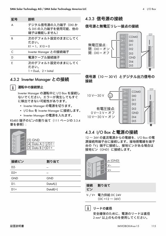
SMA Solar Technology AG / SMA Solar Technology America LLC 4 I/O Box
設置説明書 IMVIOBOX-IA-xx-15 115
4.3.2 Inverter Manager との接続
RS485 端子のピンの割り当て(111 ページの 3.3.4章を参照):
4.3.3 信号源の接続
信号源と無電圧リレー接点の接続
信号源(10 ~ 30 V)とデジタル出力信号の接続
4.3.4 I/O Box と電源の接続12 ~ 36V の直流電源からの電線を、I/O Box の電源接続用端子台に接続します。接地側電線を端子台の「V」端子に接続し、接地ピンがある場合は接地ピン(GND)に接続します。
記号 説明
A デジタル信号源の入力端子(DI0 から DI5 の入力端子を使用可能、他の端子は機能しません)
B 次のデフォルト設定のままにしてください。 X1 = 1、X10 = 0
C Inverter Manager との接続端子
D 電源ケーブル接続端子
E 次のデフォルト設定のままにしてください。 1 = Dual、2 = Initial
運転中の接続禁止
Inverter Manager の運転中に I/O Box を接続しないでください。エラーが発生してもすぐに検出できない可能性があります。
• Inverter Manager の電源を切ります。• I/O Box を Inverter Manager に接続します。• Inverter Manager の電源を入れます。
接続ピン 割り当て
D2- ---
D2+ ---
GND GND
D1- DataA(-)
D1+ DataB(+)
(5) GND
(3) Data B (+)D1+(4) Data A (−)/D1−
接続ピン
割り当て
V- / V+ 電力供給 DC 24V (DC +12 ~ 36V)
リードの直径
安全確保のために、電源のリードは直径 2 mm² 以上のものを使用してください。
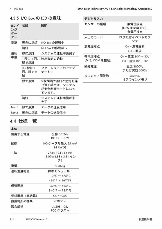
4 I/O Box SMA Solar Technology AG / SMA Solar Technology America LLC
116 IMVIOBOX-IA-xx-15 設置説明書
4.3.5 I/O Box の LED の意味
4.4 仕様一覧
LED インジケーター
状態 説明
電源 黄色に点灯 I/O Box の運転中
消灯 I/O Box の作動なし
運転準備
緑に点灯 システムの運転準備完了
1 秒に 1 回、緑で点滅
検出機能の始動
0.5 秒に 1回、緑で点滅
ファームウェアのアップデート中
緑で点滅 5 秒間隔で点灯と消灯を繰り返す場合は、システムが安全制御モードになっています。
消灯 システムの運転準備が未完了
Port 1 緑で点滅 データの送受信中
Port 2 黄色に点滅 データの送受信中
本体
使用する電源 公称 DC 24VDC 12 ~ 36V
配線 I/O ケーブル 大 25 mm² (4 AWG)
寸法 27.8x 124 x 84 mm(1.09 x 4.88 x 3.31 イン
チ)
重量 < 200 g
運転温度範囲 標準モジュール:-10°C ~ +75°C
(14°F ~ 167°F)
保管温度 -40°C ~ +85°C(-40°F ~ 185°F)
相対湿度(非結露) 5% ~ 95%
設置場所の標高 < 2000 m
適合規格 UL 508、CE、FCC クラス A
デジタル入力
センサーの種類 無電位接点(NPN または PNP)、
有電圧接点
入出力モード DI またはイベントカウンタ
無電圧接点 On = 漏電遮断Off = 開放
有電圧接点 (DI と COM を接続)
On = 直流 10V ~ 30VOff = 直流 0V ~ 3V
絶縁電圧 直流 3000V、または実効 2000V
カウンタ / 周波数 250 Hz、オフラインメモリ

SMA Solar Technology AG / SMA Solar Technology America LLC 5 LCS ツール
設置説明書 IMVIOBOX-IA-xx-15 117
5 LCS ツールパワーコンディショナと Inverter Manager は、サービスツール(LCS ツール)を使って試運転調整を行う必要があります。パワーコンディショナを系統に接続して給電を開始する前に、試運転調整が必要です。 LCS ツールは 新バージョンをお使いになることをお勧めします。LCS ツールは、www.SMA-Solar.com からダウンロードできます。LCS ツールに必要なハードウェアの条件は次のとおりです。
• WindowsTM 7 以降を搭載した PC• 1 GB のハードディスク容量• 2 GB の RAM
LCS ツールは、PC のローカルドライブにインストールする必要があります。PC は、ルーター
(推奨:DHCP)を介して、Inverter Manager の LAN 1 ポートに接続する必要があります。
図 7LCS ツールによる試運転調整 5.1 試運転調整について1. LCS ツールを起動します。LCS ツールが検出し
た Inverter Manager を示す画面が開きます。LCS ツールがすべての Inverter Manager を検出するのに数分かかる場合があります。
2. 検出されたすべての Inverter Manager が画面にリストされます(図 8 を参照)。設定したいInverter Manager をクリックして、ウィザードを起動します。クリックした Inverter Managerで認識されたパワーコンディショナがすべて表示されます。パワーコンディショナが試運転調整されていない(系統連系要件が割り当てられていない)場合は、青い四角で当該のソフトウェアバージョンが表示されます。
情報Inverter Manager の LAN 1 ポートには、このポートに接続している DHCP サーバーによって、IP アドレスが割り当てられなければなりません。IP アドレスは、Inverter Manager に手動で割り当てることができます。LCS ツールを実行する PC は、Inverter Manager と同じサブネットにある IP アドレスを持っていなければなりません。 Inverter Manager に、システムネットワークの 192.168.4.0/24 の範囲にある IP アドレスを割り当てることはできません。LAN 2 ポートは、パワーコンディショナとの接続専用です。
A LCS ツール
B ルーター(推奨:DHCP )
C Inverter Manager
D パワーコンディショナ
E LAN 1
F LAN 2

5 LCS ツール SMA Solar Technology AG / SMA Solar Technology America LLC
118 IMVIOBOX-IA-xx-15 設置説明書
図 8LCS ツール - 起動画面
3. ユーザーグループのパスワードを入力して登録手続きを行います。入力したパスワードの強度が表示されます。
4. 9 日付と時刻が正しいかどうかを確認します。間違っている場合は、正しい日時に設定してから、次の手順に進みます(図を参照)。
図 9LCS ツール - 日付と時刻の確認

SMA Solar Technology AG / SMA Solar Technology America LLC 5 LCS ツール
設置説明書 IMVIOBOX-IA-xx-15 119
5. 必要に応じて、Inverter Manager の名前と設置場所、所有者を指定することができます(図10 を参照)。
図 10LCS ツール - 太陽光発電システムの詳細
6. 選択した Inverter Manager で認識されたパワーコンディショナのリストが表示されます(図11 を参照)。
すべてのパワーコンディショナが表示されていることを確認してください。検出されていないパワーコンディショナがあっても、リストされているパワーコンディショナの設定を続行することができます。ここで検出されなかったパワーコンディショナは、後で設定してください。

5 LCS ツール SMA Solar Technology AG / SMA Solar Technology America LLC
120 IMVIOBOX-IA-xx-15 設置説明書
図 11LCS ツール - 接続されているパワーコンディショナのリスト
7. パワーコンディショナが設置されている国をリストから選択します(図 12 を参照)。
8. 12 選択した国で使用可能な系統連系要件のリストから、目的の系統連系要件を選択します。独自の系統連系要件ファイルを読み込む場合
は、[Load]ボタンをクリックします(図を参照)。[Create]は無効になっているので、 使用することはできません。
図 12LCS ツール - 国と系統連系要件の選択

SMA Solar Technology AG / SMA Solar Technology America LLC 5 LCS ツール
設置説明書 IMVIOBOX-IA-xx-15 121
9. LCS ツールは、選択した国と系統連系要件の確認を求めます(図 13 参照)。設定を変更する場合は、[Back]ボタンをクリックして前の画面に戻り、操作をやり直します。
図 13LCS ツール - 選択した国と系統連系要件の確認
10. この Inverter Manager 用に選択した系統連系要件が、検出されたパワーコンディショナに適用されます。後で追加したパワーコンディショナにも、同じ系統連系要件が自動的に適用されます。Inverter Manager 1 台につき 1 つの系統連系要件しか選択できません。
11. 14 試運転調整の完了したパワーコンディショナは、緑の四角で示されます。タイトルバーの下にある[Start]ボタンをクリックすることで、パワーコンディショナが初めて系統と解列状態になります(図を参照)。
情報正しい系統連系要件を選択することが重要です。初めて運転を開始してから 10 時間経過した後で系統連系要件を変更するには、各人に割り当てられた SMA Grid Guard コードが必要になります。系統連系要件パラメータは、LCS ツール
(130 ページの 5.2.6 章を参照)で後から変更できます。 新バージョンの LCS ツールを使っていることが前提となります。

5 LCS ツール SMA Solar Technology AG / SMA Solar Technology America LLC
122 IMVIOBOX-IA-xx-15 設置説明書
図 14LCS ツール - Inverter Manager に接続されているパワーコンディショナのリスト
12. 十分な電力が発電され、系統連系条件が満たされると、パワーコンディショナの運転が開始されます。
13. 15 試運転調整の実施時には、[Reports]メニューを使用して、試運転調整報告書をダウンロードすることができます。報告書には、
それぞれのパワーコンディショナを実際に解列する値を含む、パワーコンディショナの設定の情報が示されます。[Reports]メニューからフォルダーアイコンをクリックすると、試運転調整報告書(系統連系要件に関する情報を含む)のフォルダーを開くことができます
(を参照)。
図 15LCS ツール - 試運転調整報告書

SMA Solar Technology AG / SMA Solar Technology America LLC 5 LCS ツール
設置説明書 IMVIOBOX-IA-xx-15 123
5.2 LCS ツールの使用
5.2.1 パスワードを忘れた場合
図 16LCS ツール - パスワードを忘れた場合
ユーザーインターフェースのパスワードを忘れた場合は、PUK(Personal Unlocking Key:個人用ロック解除キー)を使ってログインします。ユーザーグループごとに固有の PUK が割り当てられています。
手順:1. PUK の発行を依頼します(www.SMA-Solar.com
で、PUK の発行依頼手順を確認してください)。
2. LCS ツールを起動します。3.[User]または[Installer]のユーザーグループ
を選択します。4. パスワードの代わりに、発行された PUK を入
力します。5.[Setup]メニューを開きます。6.[Password]で、該当するユーザーグループの
パスワードを変更します。7.[Save]を選択して、変更を保存します。

5 LCS ツール SMA Solar Technology AG / SMA Solar Technology America LLC
124 IMVIOBOX-IA-xx-15 設置説明書
5.2.2 系統連系要件の変更
図 17LCS ツール - SMA Grid Guard コードの入力
Inverter Manager を始動させてから 10 時間経った後で、別の国の系統連系要件に変更するには、
[Installer]ユーザーグループに属するユーザーとして、SMA Grid Guard コードを使用します
(www.SMA-Solar.com で、SMA Grid Guard コードの申込書を確認してください)。
手順:1. LCS ツールを起動します。2.[Installer]してログインします。3.[Service]メニューを開きます。4.[Grid Guard]の[Individual access code]欄に
SMA Grid Guard コードを入力します。5.[Save]を選択して、変更を保存します。
☑ [Setup]メニューに、新しい [General]というメニュー項目が追加されます。

SMA Solar Technology AG / SMA Solar Technology America LLC 5 LCS ツール
設置説明書 IMVIOBOX-IA-xx-15 125
5.2.3 ファームウェアを更新する
図 18LCS ツール - ファームウェアの手動アップデート
Inverter Manager のファームウェアを手動でアップデートすることができます。LCS ツールは 新バージョンをお使いになることをお勧めします。LCS ツールは、www.SMA-Solar.com からダウンロードできます。
手順:1. LCS ツールを起動します。2.[User]または[Installer]としてログインしま
す。3.[Service]メニューを開きます。4.[Software Update]の[Inverter manager]タブを
選択します。5.[Start update]を選択して、アップデートを開
始します。 ☑ アップデートが開始されます。
アップデート手順の中断による製品ダメージについてInverter Manager と PC の接続が途切れると、機器を破損する恐れがあります。
• アップデートが完了するまで、Inverter Manager と PC の接続を切断しないでください。
• PC と Inverter Manager は電源につなげたままにしておいてください。
• PC は省エネモードに切り替えないでください。

5 LCS ツール SMA Solar Technology AG / SMA Solar Technology America LLC
126 IMVIOBOX-IA-xx-15 設置説明書
5.2.4 システムの通信断時の設定
図 19LCS ツール - 通信断時パラメータの設定
(124 ページの 5.2.2 章を参照)Inverter Manager と上位制御ユニット(SCADA システムや Power Plant Controller など)との間に通信不具合が発生した場合に備えて、システムの通信断時設定しておくことが可能です。上位システムの通信断時設定 LCSツールを介してのみ設定可能です。上位フォールバックに関する値を設定するには、[Installer]ユーザーグループに属するユーザーとして、 SMA Grid Guard コードを使用します。
手順:1. LCS ツールを起動します。2.[Installer]してログインします。3.[Setup]メニューを開きます。4.[Plant fallback]の値をそれぞれ入力します。5.[Save]を選択して、変更を保存します。
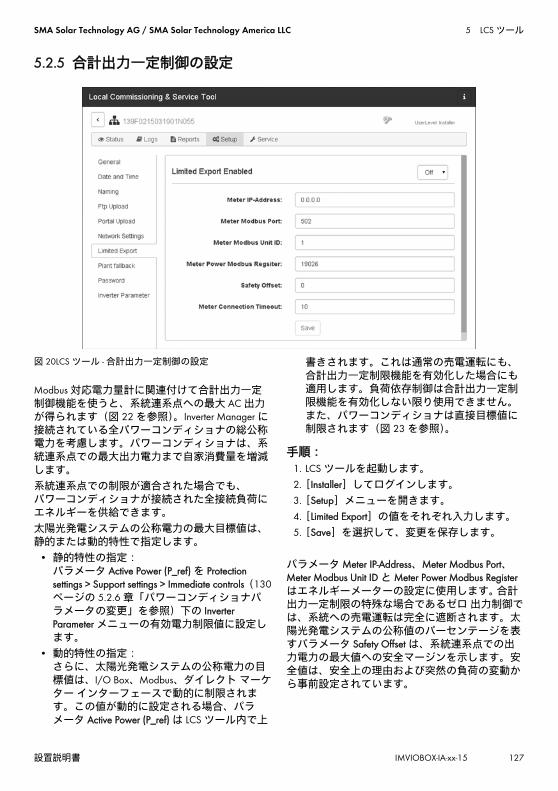
SMA Solar Technology AG / SMA Solar Technology America LLC 5 LCS ツール
設置説明書 IMVIOBOX-IA-xx-15 127
5.2.5 合計出力一定制御の設定
図 20LCS ツール - 合計出力一定制御の設定
Modbus 対応電力量計に関連付けて合計出力一定制御機能を使うと、系統連系点への 大 AC 出力が得られます(図 22 を参照)。Inverter Manager に接続されている全パワーコンディショナの総公称電力を考慮します。パワーコンディショナは、系統連系点での 大出力電力まで自家消費量を増減します。 系統連系点での制限が適合された場合でも、 パワーコンディショナが接続された全接続負荷にエネルギーを供給できます。太陽光発電システムの公称電力の 大目標値は、静的または動的特性で指定します。
• 静的特性の指定: パラメータ Active Power (P_ref) を Protection settings > Support settings > Immediate controls(130ページの 5.2.6 章「パワーコンディショナパラメータの変更」を参照)下の Inverter Parameter メニューの有効電力制限値に設定します。
• 動的特性の指定: さらに、太陽光発電システムの公称電力の目標値は、I/O Box、Modbus、ダイレクト マーケター インターフェースで動的に制限されます。この値が動的に設定される場合、パラメータ Active Power (P_ref) は LCS ツール内で上
書きされます。これは通常の売電運転にも、合計出力一定制限機能を有効化した場合にも適用します。負荷依存制御は合計出力一定制限機能を有効化しない限り使用できません。また、パワーコンディショナは直接目標値に制限されます(図 23 を参照)。
手順:1. LCS ツールを起動します。2.[Installer]してログインします。3.[Setup]メニューを開きます。4.[Limited Export]の値をそれぞれ入力します。5.[Save]を選択して、変更を保存します。
パラメータ Meter IP-Address、Meter Modbus Port、Meter Modbus Unit ID と Meter Power Modbus Registerはエネルギーメーターの設定に使用します。 合計出力一定制限の特殊な場合であるゼロ 出力制御では、系統への売電運転は完全に遮断されます。太陽光発電システムの公称値のパーセンテージを表すパラメータ Safety Offset は、系統連系点での出力電力の 大値への安全マージンを示します。安全値は、安全上の理由および突然の負荷の変動から事前設定されています。

5 LCS ツール SMA Solar Technology AG / SMA Solar Technology America LLC
128 IMVIOBOX-IA-xx-15 設置説明書
これにより、目標値への安全マージンが確保されています。有効化処理においては、目標値は安全値まで減じられます。よって、売電電力は常に実際の目標値を下回ります。パラメータ Meter Connection Timeout は、電力量計への通信が途絶えた場合に、太陽光発電システムの公称電力を 0 W に調節するために必要な時間を秒で指定します。現在のシステム値の概要を得るには、Status メニューを開けて Overview を選択します(図 21 を参照)。
図 21LCS ツール - 現在のシステム値の概要
Modbus 制御この制限値を恒久的に設定する場合、Modbus レジスタ 40349 に必要な値を設定します。合計出力一定制限機能の作動中に系統から直ちにパワーコンディショナを切断するには、Modbus レジスタ 40348 に値「0」を設定します。Modbus インターフェースについての詳細は、www.SMA-Solar.com にて技術情報
「SUNNY TRIPOWER 60 / SUNNY HIGHPOWER PEAK1- SunSpec® Modbus® Interface」を参照してください。

SMA Solar Technology AG / SMA Solar Technology America LLC 5 LCS ツール
設置説明書 IMVIOBOX-IA-xx-15 129
図 22 合計出力一定制限下での売電運転
図 23 合計出力一定制御制限が無い場合の売電運転
A パワーコンディショナ
B Inverter Manager
C 負荷
D 系統
E 系統連系点
F Modbus TCP
G AC

5 LCS ツール SMA Solar Technology AG / SMA Solar Technology America LLC
130 IMVIOBOX-IA-xx-15 設置説明書
5.2.6 パワーコンディショナパラメータの変更
図 24LCS ツール - パワーコンディショナパラメータの変更
パワーコンディショナのパラメータはすべて、Grid Guard で保護されており、変更には Grid Guard コードが必要です。パワーコンディショナの設定を変更するには、[Installer] (124 ページの 5.2.2 章を参照)ユーザーグループに属するユーザーとして、SMA Grid Guard コードを使用します。
手順:1. LCS ツールを起動します。2.[Installer]してログインします。3.[Setup]メニューを開きます。4.[Inverter Parameter]のそれぞれの値を入力しま
す。5.[Save]を選択して、変更を保存します。
パワーコンディショナパラメータの無効化 /有効化パラメータを無効化したり有効化したりするには、マウスの左ボタンでそのパラメータをダブルクリックします。 パラメータが有効化されると、入力フィールドとボタンが使用可能になります。無効化されているパラメータには[disable]の印が付きます。

SMA Solar Technology AG / SMA Solar Technology America LLC 5 LCS ツール
設置説明書 IMVIOBOX-IA-xx-15 131
図 25LCS ツール - パワーコンディショナパラメータの無効化 / 有効化
力率パラメータのサインの変更力率パラメータのサインを変更するには、マウスの左ボタンでそのサインをクリックします。
図 26LCS ツール - サインの変更

5 LCS ツール SMA Solar Technology AG / SMA Solar Technology America LLC
132 IMVIOBOX-IA-xx-15 設置説明書
I/O Box パラメータの設定サブメニュー[I/O Box]のパラメータを入力するには、マウスで入力フィールドを右クリックします。
図 27LCS ツール - I/O Box パラメータの設定
5.2.7 ログ[Logs]メニューからは、イベント履歴情報、運転
性能データ、パラメータ指定、パワーコンディショナパラメータの変更が閲覧できます。
図 28LCS ツール - ログ