Embed Size (px)
Citation preview

AIO338xU
Analog Input and
Multi-Function Digital I/O Card
Software Manual (V2.1)
健昇科技股份有限公司
JS AUTOMATION CORP.
新北市汐止區中興路 100號 6樓
6F., No.100, Zhongxing Rd., Xizhi Dist., New Taipei City, Taiwan 電話(TEL):+886-2-2647-6936
傳真(FAX):+886-2-2647-6940
http://www.automation.com.tw
http://www.automation-js.com/ E-mail:[email protected]

1
Correction record
Version Record
1.0 First publish
V1.0->V1.1 Modify the order of the contents (flow chart)
V1.1->V2.0 disable the software key function with return value always true
V2.0->V2.1 dll v2.1 and later add arbitrary waveform function
AIO3380U_DA_Arbitrary_Waveform_Start( )
AIO3380U_DA_Arbitrary_Waveform_Stop( )
AIO3380U_DA_Arbitrary_Waveform_data_set( )
AIO3380U_DA_Arbitrary_Waveform_data_read( )

2
Contents
1. Difference between AIO3380 and AIO3380U ................................................................................. 5
AIO3380_set_timer ................................................................................................................. 7
AIO3380_set_counter .............................................................................................................. 8
AIO3380_set_pwm .................................................................................................................. 9
AIO3380_one_shot_command ................................................................................................ 9
AIO3380_set_gate_CNTR..................................................................................................... 10
2. How to install the software of AIO3380U ..................................................................................... 11
2.1 Install the PCI driver ............................................................................................................ 11
3. Where to find the file you need ..................................................................................................... 12
4. About the AIO3380U software ...................................................................................................... 13
4.1 What you need to get started ................................................................................................ 13
4.2 Software programming choices ........................................................................................... 13
5. AIO3380U Language support ........................................................................................................ 14
5.1 Building applications with the AIO3380U software library ................................................ 14
5.2 AIO3380U Windows libraries ............................................................................................. 14
6. Function format and language difference ...................................................................................... 15
6.1 Function format.................................................................................................................... 15
6.2 Variable data types ............................................................................................................... 16
6.3 Programming language considerations ................................................................................ 17
7. Flow chart of application implementation ..................................................................................... 19
7.1 AIO3380U Flow chart of application implementation ........................................................ 19
7.2 AIO3380U Flow chart of Timer / Counter / PWM application ........................................... 20
7.3 AIO3380U Flow chart of interrupt ...................................................................................... 21
8. Software overview and dll function ............................................................................................... 22
8.1 Initialization and close ......................................................................................................... 22
AIO3380U_initial .................................................................................................................. 22
AIO3380U_initial_calibration ............................................................................................... 22
AIO3380U_close ................................................................................................................... 22
AIO3380U_info ..................................................................................................................... 23
8.2 Analog input ........................................................................................................................ 24
AIO3380U_AD_config_set ................................................................................................... 24
AIO3380U_AD_config_read................................................................................................. 25
AIO3380U_AD_value_read .................................................................................................. 25
AIO3380U_AD_value_read_no_calibration ......................................................................... 26
AIO3380U_AD_data_read_no_calibration ........................................................................... 26
AIO3380U_AD_integral_start............................................................................................... 27
AIO3380U_AD_integral_all_read......................................................................................... 27
AIO3380U_AD_integral_stop ............................................................................................... 28
8.3 Analog output ...................................................................................................................... 29

3
AIO3380U_DA_set ............................................................................................................... 29
AIO3380U_DA_read ............................................................................................................. 30
AIO3380U_DA_Arbitrary_Waveform_data_set ................................................................... 31
AIO3380U_DA_Arbitrary_Waveform_data_read ................................................................ 32
AIO3380U_DA_Arbitrary_Waveform_Start ........................................................................ 33
AIO3380U_DA_Arbitrary_Waveform_Stop ......................................................................... 33
8.4 TTL I/O Port R/W ................................................................................................................ 34
AIO3380U_TTL_IO_config_set ........................................................................................... 35
AIO3380U_TTL_IO_config_read ......................................................................................... 36
AIO3380U_TTL_IO_port_set ............................................................................................... 36
AIO3380U_TTL_IO_port_read............................................................................................. 37
AIO3380U_TTL_IO_point_set ............................................................................................. 37
AIO3380U_TTL_IO_point_read ........................................................................................... 38
AIO3380U_TTL_IO_debounce_time_set ............................................................................. 38
AIO3380U_TTL_IO_debounce_time_read........................................................................... 39
8.5 Counter / Timer / PWM function ......................................................................................... 40
AIO3380U_timer_set............................................................................................................. 45
AIO3380U_counter_set ......................................................................................................... 47
AIO3380U_PWM_set ........................................................................................................... 49
AIO3380U_quadrature_set .................................................................................................... 50
AIO3380U_TC_start ............................................................................................................. 50
AIO3380U_TC_stop .............................................................................................................. 50
AIO3380U_TC_set ................................................................................................................ 51
AIO3380U_TC_read ............................................................................................................. 52
AIO3380U_TC_input_polarity_set ....................................................................................... 54
AIO3380U_TC_input_polarity_read ..................................................................................... 54
AIO3380U_TC_output_polarity_set ..................................................................................... 55
AIO3380U_TC_output_polarity_read ................................................................................... 55
8.6 Interrupt function ................................................................................................................. 56
AIO3380U_IRQ_link_process .............................................................................................. 56
AIO3380U_IRQ_enable ........................................................................................................ 56
AIO3380U_IRQ_disable ....................................................................................................... 57
AIO3380U_IRQ_mask_set .................................................................................................... 57
AIO3380U_IRQ_mask_read ................................................................................................. 58
AIO3380U_IRQ_IO_polarity_set ......................................................................................... 59
AIO3380U_IRQ_IO_polarity_read ....................................................................................... 59
AIO3380U_IRQ_status_read................................................................................................. 60
8.7 Security function .................................................................................................................. 61
AIO3380U_password_set ...................................................................................................... 61
AIO3380U_password_change ............................................................................................... 61
AIO3380U_password_clear................................................................................................... 62

4
AIO3380U_security_unlock .................................................................................................. 62
AIO3380U_security_status_read ........................................................................................... 62
8.8 Error conditions ................................................................................................................... 63
9. Dll list ........................................................................................................................................... 64
10. AIO3380U Error codes summary .................................................................................................. 66
10.1 AIO3380U Error codes table ............................................................................................... 66
5
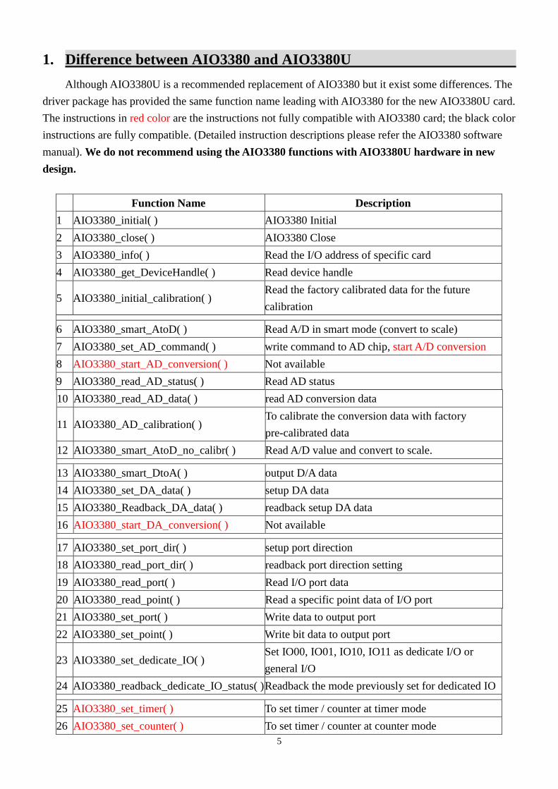
1. Difference between AIO3380 and AIO3380U
Although AIO3380U is a recommended replacement of AIO3380 but it exist some differences. The
driver package has provided the same function name leading with AIO3380 for the new AIO3380U card.
The instructions in red color are the instructions not fully compatible with AIO3380 card; the black color
instructions are fully compatible. (Detailed instruction descriptions please refer the AIO3380 software
manual). We do not recommend using the AIO3380 functions with AIO3380U hardware in new
design.
Function Name Description
1 AIO3380_initial( ) AIO3380 Initial
2 AIO3380_close( ) AIO3380 Close
3 AIO3380_info( ) Read the I/O address of specific card
4 AIO3380_get_DeviceHandle( ) Read device handle
5 AIO3380_initial_calibration( ) Read the factory calibrated data for the future
calibration
6 AIO3380_smart_AtoD( ) Read A/D in smart mode (convert to scale)
7 AIO3380_set_AD_command( ) write command to AD chip, start A/D conversion
8 AIO3380_start_AD_conversion( ) Not available
9 AIO3380_read_AD_status( ) Read AD status
10 AIO3380_read_AD_data( ) read AD conversion data
11 AIO3380_AD_calibration( ) To calibrate the conversion data with factory
pre-calibrated data
12 AIO3380_smart_AtoD_no_calibr( ) Read A/D value and convert to scale.
13 AIO3380_smart_DtoA( ) output D/A data
14 AIO3380_set_DA_data( ) setup DA data
15 AIO3380_Readback_DA_data( ) readback setup DA data
16 AIO3380_start_DA_conversion( ) Not available
17 AIO3380_set_port_dir( ) setup port direction
18 AIO3380_read_port_dir( ) readback port direction setting
19 AIO3380_read_port( ) Read I/O port data
20 AIO3380_read_point( ) Read a specific point data of I/O port
21 AIO3380_set_port( ) Write data to output port
22 AIO3380_set_point( ) Write bit data to output port
23 AIO3380_set_dedicate_IO( ) Set IO00, IO01, IO10, IO11 as dedicate I/O or
general I/O
24 AIO3380_readback_dedicate_IO_status( ) Readback the mode previously set for dedicated IO
25 AIO3380_set_timer( ) To set timer / counter at timer mode
26 AIO3380_set_counter( ) To set timer / counter at counter mode

6
27 AIO3380_set_pwm( ) Set timer/counter at PWM mode
28 AIO3380_set_clock_frequency( ) Not available
29 AIO3380_load_GPT( ) Write data to GPT(general purpose timer/counter
register)
30 AIO3380_read_GPT( ) Read GPT(general purpose timer/counter register)
data
31 AIO3380_GPT_enable( ) Enable/disable timer/counter function
32 AIO3380_one_shot_command( ) Generate an one shot
33 AIO3380_set_gate_CNTR( ) Set gated counter function
34 AIO3380_read_parameter( ) Read parameter from timer/counter
35 AIO3380_enable_IRQ( ) Enable interrupt of timer/counter
36 AIO3380_link_IRQ_process( ) Link IRQ process
37 AIO3380_disable_IRQ( ) Disable interrupt of timer/counter
38 AIO3380_read_IRQ_status( ) Readback IRQ status
39 AIO3380_set_password( ) Set password
40 AIO3380_change_password( ) Change password
41 AIO3380_clear_password( ) Clear password
42 AIO3380_unlock_security( ) Unlock security function
43 AIO3380_read_security_status( ) Read security status

7
Instructions that are different from the previous AIO3380 card
AIO3380_set_timer
Format : u32 status = AIO3380_set_timer(u8 CardID,u8 TimerID, u8 To_mode )
Purpose: To set timer / counter at timer mode and configure its timer output function.
Parameters:
Input:
Name Type Description
CardID u8 assigned by DIP/ROTARY SW
TimerID u8 timer/counter designation
0: timer/counter0
1: timer/counter1
To_mode u8 designation of timer output mode:
0: To will pulse low for 1us when
terminal count is reached
1: To will pulse low for 2us when
terminal count is reached
2: To will toggle whenever terminal
count is reached
3: no output function
Note: Time base is only 1us only.
8
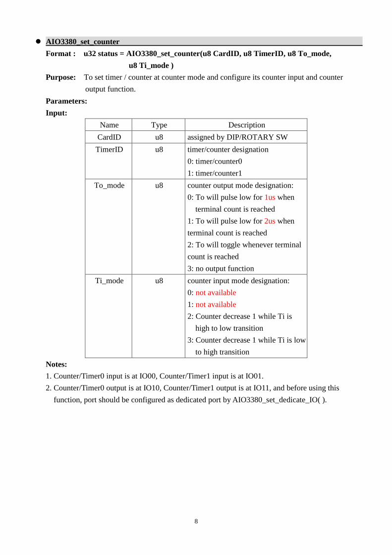
AIO3380_set_counter
Format : u32 status = AIO3380_set_counter(u8 CardID, u8 TimerID, u8 To_mode,
u8 Ti_mode )
Purpose: To set timer / counter at counter mode and configure its counter input and counter
output function.
Parameters:
Input:
Name Type Description
CardID u8 assigned by DIP/ROTARY SW
TimerID u8 timer/counter designation
0: timer/counter0
1: timer/counter1
To_mode u8 counter output mode designation:
0: To will pulse low for 1us when
terminal count is reached
1: To will pulse low for 2us when
terminal count is reached
2: To will toggle whenever terminal
count is reached
3: no output function
Ti_mode u8 counter input mode designation:
0: not available
1: not available
2: Counter decrease 1 while Ti is
high to low transition
3: Counter decrease 1 while Ti is low
to high transition
Notes:
1. Counter/Timer0 input is at IO00, Counter/Timer1 input is at IO01.
2. Counter/Timer0 output is at IO10, Counter/Timer1 output is at IO11, and before using this
function, port should be configured as dedicated port by AIO3380_set_dedicate_IO( ).

9
AIO3380_set_pwm
Format : u32 status = AIO3380_set_pwm(u8 CardID,u8 TimerID )
Purpose: To set timer/counter at PWM mode and map the PWM output to port1 bit n for
timer/counter n.
Parameters:
Input:
Name Type Description
CardID u8 assigned by DIP/ROTARY SW
TimerID u8 timer/counter designation
0: timer/counter0
1: timer/counter1
Note: Each timer/counter has 32 bit register length, if you program as PWM mode, the register is
divided as 2 16 bit width, the lower 16 bit work as the PWM duty width and the upper 16 bit work
as PWM frequency register.
AIO3380_one_shot_command
Format : status=AIO3380_one_shot_command (u8 CardID,u8 TimerID, u16
duration_time)
Purpose: To generate an one shot output from timer0/1 at programmed duration
Parameters:
Input:
Name Type Description
CardID u8 assigned by DIP/ROTARY SW
TimerID u8 timer/counter designation
0: timer/counter 0 , output at DIO10
1: timer/counter 1 , output at DIO11
duration_time u16 the duration time constant of one shot.
Duration time = time constant *1us
Notes:
Counter/Timer0 output is at IO10, Counter/Timer1 output is at IO11, and before using this
function, port should be configured as dedicated port by AIO3380_set_dedicate_IO( ).

10
AIO3380_set_gate_CNTR
Format : u32 status = AIO3380_set_gate_CNTR(u8 CardID,u8 TimerID,u8 enable)
Purpose: To enable/disable gated timer/counter function and the gated input for timer0/timer1.
Parameters:
Input:
Name Type Description
CardID u8 assigned by DIP/ROTARY SW
TimerID u8 port designation
0: timer/counter0
1: timer/counter1
enable u8 0: disable gated timer/counter
function
1: enable or resume timer/counter
function
for Counter/Timer0, the gate
input :
DIO00: counter input
DIO02: gate input, high enables
counting
for Counter/Timer1, the gate input :
DIO01: counter input
DIO03: gate input, high enables
counting

11
2. How to install the software of AIO3380U
2.1 Install the PCI driver
The PCI card is a plug and play card, once you add a new card the on window system will detect
while it is booting. Please follow the following steps to install your new card.
In WinXP/7 and up system you should: (take Win XP as example)
1. Make sure the power is off
2. Plug in the interface card
3. Power on
4. A hardware install wizard will appear and tell you it finds a new PCI card
5. Do not response to the wizard, just Install the file
(..\AIO3382_4U\Software\WinXP_7\ or if you download from website please execute the file
AIO3380U_Install.exe to get the file)
6. After installation, power off
7. Power on, it’s ready to use
Note: AIO3382U, AIO3382UA, AIO3382UB, AIO3384U, AIO3384UAA, AIO3384UAB,
AIO3384UBB use the same driver and dll.
For more detail of step by step installation guide, please refer the file “installation.pdf “ on the CD
come with the product or register as a member of our user’s club at:
http://automation.com.tw/
to download the complementary documents.

12
3. Where to find the file you need
WinXP/7 and up
The directory will be located at
.. \ JS Automation \AIO3380U\API\ (header files and lib files for VB,VC,BCB,C#)
.. \ JS Automation \AIO3380U\Driver\ (backup copy of AIO3380U drivers)
.. \ JS Automation \AIO3380U\exe\ (demo program and source code)
The system driver is located at ..\system32\Drivers and the DLL is located at ..\system.
For your easy startup, the demo program with source code demonstrates the card functions and help
file.

13
4. About the AIO3380U software
AIO3380U software includes a set of dynamic link library (DLL) and system driver that you can
utilize to control the I/O card’s ports and points separately.
Your AIO3380U software package includes setup driver, tutorial example and test program that
help you how to setup and run appropriately, as well as an executable file which you can use to test each
of the AIO3380U functions within Windows’ operation system environment.
4.1 What you need to get started
To set up and use your AIO3380U software, you need the following:
AIO3380U software
AIO3380U hardware
Main board
Wiring board (Option)
4.2 Software programming choices
You have several options to choose from when you are programming AIO3380U software. You can
use Borland C/C++, Microsoft Visual C/C++, Microsoft Visual Basic, or any other Windows-based
compiler that can call into Windows dynamic link libraries (DLLs) for use with the AIO3380U software.

14
5. AIO3380U Language support
The AIO3380U software library is a DLL used with WinXP/7 and up. You can use these DLL with
any Windows integrating development environment that can call Windows DLLs.
5.1 Building applications with the AIO3380U software library
The AIO3380U function reference topic contains general information about building AIO3380U
applications, describes the nature of the AIO3380U files used in building AIO3380U applications, and
explains the basics of making applications using the following tools:
Applications tools
Microsoft Visual C/C++
Borland C/C++
Microsoft Visual C#
Microsoft Visual Basic
Microsoft VB.net
If you are not using one of the tools listed, consult your development tool reference manual for
details on creating applications that call DLLs.
5.2 AIO3380U Windows libraries
The AIO3380U for Windows function library is a DLL called AIO3380U.dll. Since a DLL is used,
AIO3380U functions are not linked into the executable files of applications. Only the information about
the AIO3380U functions in the AIO3380U import libraries is stored in the executable files.
Import libraries contain information about their DLL-exported functions. They indicate the
presence and location of the DLL routines. Depending on the development tools you are using, you can
make your compiler and linker aware of the DLL functions through import libraries or through function
declarations.
Refer to Table 1 to determine to which files you need to link and which to include in your
development to use the AIO3380U functions in AIO3380U.dll.
Header Files and Import Libraries for Different Development Environments
Language Header File Import Library
Microsoft Visual C/C++ AIO3380U.h AIO3380UVC.lib
Borland C/C++ AIO3380U.h AIO3380UBC.lib
Microsoft Visual C# AIO3380U.cs
Microsoft Visual Basic AIO3380U.bas
Microsoft VB.net AIO3380U.vb
Table 1

15
6. Function format and language difference
6.1 Function format
Every AIO3380U function is consist of the following format:
Status = function_name (parameter 1, parameter 2, … parameter n)
Each function returns a value in the Status global variable that indicates the success or failure of
the function. A returned Status equal to zero that indicates the function executed successfully. A
non-zero status indicates failure that the function did not execute successfully because of an error, or
executed with an error.
Note : Status is a 32-bit unsigned integer.
The first parameter to almost every AIO3380U function is the parameter CardID which is located
the driver of AIO3380U board you want to use those given operation. The CardID is assigned by
DIP/ROTARY SW. You can utilize multiple devices with different card CardID within one application;
to do so, simply pass the appropriate CardID to each function.
Note: CardID is set by DIP/ROTARY SW (0x0-0xF)

16
6.2 Variable data types
Every function description has a parameter table that lists the data types for each parameter. The
following sections describe the notation used in those parameter tables and throughout the manual for
variable data types.
Primary Type Names
Name Description Range C/C++ Visual BASIC Pascal
(Borland Delphi)
u8 8-bit ASCII
character
0 to 255 char Not supported by BASIC.
For functions that require
character arrays, use
string types instead.
Byte
i16 16-bit signed
integer
-32,768 to 32,767 short Integer (for example:
deviceNum%)
SmallInt
u16 16-bit
unsigned
integer
0 to 65,535 unsigned short
for 32-bit
compilers
Not supported by BASIC.
For functions that require
unsigned integers, use the
signed integer type
instead. See the i16
description.
Word
i32 32-bit signed
integer
-2,147,483,648 to
2,147,483,647
long Long (for example:
count&)
LongInt
u32 32-bit
unsigned
integer
0 to
4,294,967,295
unsigned long Not supported by BASIC.
For functions that require
unsigned long integers,
use the signed long
integer type instead. See
the i32 description.
Cardinal (in
32-bit operating
systems). Refer to
the i32
description.
f32 32-bit
single-precisio
n
floating-point
value
-3.402823E+38 to
3.402823E+38
float Single (for example:
num!)
Single
f64 64-bit
double-precisi
on
floating-point
value
-1.797683134862
315E+308 to
1.7976831348623
15E+308
double Double (for example:
voltage Number)
Double
Table 2

17
6.3 Programming language considerations
Apart from the data type differences, there are a few language-dependent considerations you need
to be aware of when you use the AIO3380U API. Read the following sections that apply to your
programming language.
Note : Be sure to include the declaration functions of AIO3380U prototypes by including the appropriate
AIO3380U header file in your source code. Refer to Building Applications with the AIO3380U Software
Library for the header file appropriate to your compiler.
6.3.1 C/C++
For C or C++ programmers, parameters listed as Input/Output parameters or Output parameters are
pass-by-reference parameters, which means a pointer points to the destination variable should be passed
into the function. For example, the Read Port function has the following format:
Status = AIO3380U_TTL_IO_port_read(CardID, port, *data);
where CardID and port are input parameters, and data is an output parameter. Consider the following
example:
u8 CardID, port;
u8 data,
u32 Status;
Status = AIO3380U_TTL_IO_port_read (CardID, port, data);
6.3.2 Visual basic
The file AIO3380U.bas contains definitions for constants required for obtaining AIO Card
information and declared functions and variable as global variables. You should use these constants
symbols in the AIO3380U.bas, do not use the numerical values.
In Visual Basic, you can add the entire AIO3380U.bas file into your project. Then you can use any of the
constants defined in this file and call these constants in any module of your program. To add the
AIO3380U.bas file for your project in Visual Basic 4.0, go to the File menu and select the Add File...
option. Select AIO3380U.bas, which is browsed in the AIO3380U \ API directory. Then, select Open to
add the file to the project.
To add the AIO3380U.bas file to your project in Visual Basic 5.0 and 6.0, go to the Project menu
and select Add Module. Click on the Existing tab page. Select AIO3380U.bas, which is in the
AIO3380U \ API directory. Then, select Open to add the file to the project.

18
6.3.3 Borland C++ builder
To use Borland C++ builder as development tool, you should generate a .lib file from the .dll file by
implib.exe.
implib AIO3380UBC.lib AIO3380U.dll
Then add the AIO3380UBC.lib to your project and add
#include “AIO3380U.h” to main program.
Now you may use the dll functions in your program. For example, the Read Port function has the
following format:
Status = AIO3380U_TTL_IO_port_read(CardID, port, *data);
where CardID and port are input parameters, and data is an output parameter. Consider the following
example:
u8 CardID, port;
u8 data;
u32 Status;
Status =AIO3380U_TTL_IO_port_read (CardID, port, data);

19
7. Flow chart of application implementation
7.1 AIO3380U Flow chart of application implementation
Application Start
Error
Error
Step 2
Step 1
Yes
No
Initial successStatus=0?
No
Yes
Exception process
Operations of cards
Exit
End
Step 3
Initial successStatus=0?
Driver Initialstatus=AIO3380U_initial()
Calibration Initialstatus=AIO3380U_initial_calibration()
Operation of AIO3380U card Read I/O port data status=AIO3380U_TTL_IO_port_read() Write I/O port data status=AIO3380U_TTL_IO_port_set() or read A/D value status=AIO3380U_AD_value_read()
Close application Release Dll resource
status=AIO3380U_close()
20
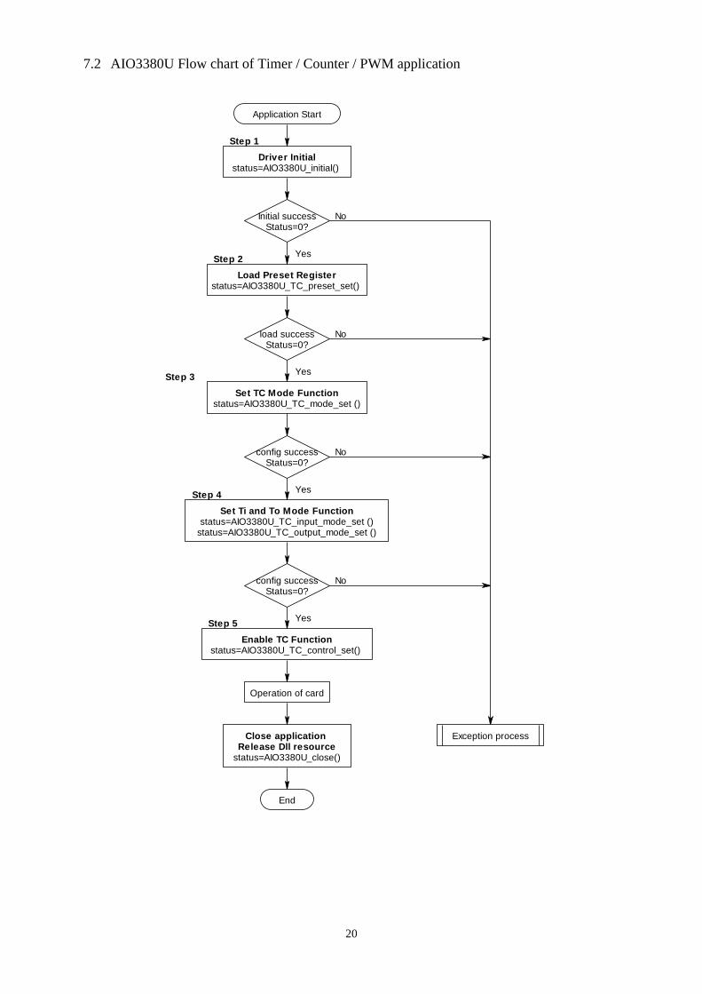
7.2 AIO3380U Flow chart of Timer / Counter / PWM application
Initial successStatus=0?
load successStatus=0?
Application Start
Step 2
Step 1
Step 3
No
No
No
Step 4
Step 5
No
Yes
Yes
Yes
Yes
config successStatus=0?
config successStatus=0?
Exception process
Operation of card
End
Driver Initialstatus=AIO3380U_initial()
Load Preset Registerstatus=AIO3380U_TC_preset_set()
Set TC Mode Functionstatus=AIO3380U_TC_mode_set ()
Set Ti and To Mode Functionstatus=AIO3380U_TC_input_mode_set ()
status=AIO3380U_TC_output_mode_set ()
Enable TC Functionstatus=AIO3380U_TC_control_set()
Close application Release Dll resource
status=AIO3380U_close()

21
7.3 AIO3380U Flow chart of interrupt
Yes
Application Start
Step 1
Initial successStatus=0?
No
YesStep 2
NoEnable successStatus=0?
Enable successStatus=0?
Link successStatus=0?
Interrupt is config OKEnd
Yes
No
Exception process
Yes
No
Step 3
Step 4
Driver Initialstatus=AIO3380U_initial()
Enable IRQstatus=AIO3380U_IRQ_enable()
IRQ Maskstatus=AIO3380U_IRQ_mask_set()
status=AIO3380U_IRQ_IO_polarity_set()
Link IRQ processstatus=AIO3380U_IRQ_link_process()

22
8. Software overview and dll function
These topics describe the features and functionality of the AIO3380U boards and briefly describes
the AIO3380U functions.
8.1 Initialization and close
You need to initialize system resource each time you start to run your application.
AIO3380U_initial( ) will do.
Before you want to A/D conversion, the factory pre-calibrated data should be initialized for A/D
conversion.
AIO3380U_initial_calibration( ) will read factory calibrated data to working area.
Once you want to close your application, call
AIO3380U_close( ) to release all the resource.
If you want to know the physical address assigned by OS. use
AIO3380U_info( ) to get the address.
AIO3380U_initial
Format : u32 status =AIO3380U_initial(void)
Purpose: Initial the AIO3380U resource when start the Windows applications.
AIO3380U_initial_calibration
Format : u32 status =AIO3380U_initial_calibration(u8 CardID)
Purpose: Read the factory pre-calibrated data for the future calibration.
Parameters:
Input:
Name Type Description
CardID u8 assigned by DIP/ROTARY SW
AIO3380U_close
Format : u32 status =AIO3380U_close(void);
Purpose: Release the AIO3380U resource when close the Windows applications.

23
AIO3380U_info
Format : u32 status =AIO3380U_info(u8 CardID,u16 *address)
Purpose: Read the physical I/O address assigned by O.S..
Parameters:
Input:
Name Type Description
CardID u8 assigned by DIP/ROTARY SW
Output:
Name Type Description
address u16 physical I/O address assigned by OS

24
8.2 Analog input
The AIO338xU now are 8 channels 16 bit AD cards. There are different channel D/A numbers for
AIO3382U (2 channels) and AIO3384U (4 channels).
You must configure the input range of the specific channel by:
AIO3380U_AD_config_set( ) and read back the configuration for verification by:
AIO3380U_AD_config_read( )
To read the input voltage value with the factory pre-calibrated data by:
AIO3380U_AD_value_read( ), it can be also read without the calibration by
AIO3380U_AD_value_read_no_calibration( )
If your application only need the raw AD data, you can read AD data by:
AIO3380U_AD_data_read_no_calibration( )
If your environment is noisy or you need to get more accurate data, you can use the integral
function built in dll by:
AIO3380U_AD_integral_start( ) to start the embedded integration of the system.
AIO3380U_AD_integral_all_read( ) to read all channels.
AIO3380U_AD_integral_stop( ) to stop integration function.
AIO3380U_AD_config_set
Format : u32 status = AIO3380U_AD_config_set(u8 CardID,u8 channel,u8 mode)
Purpose: Set A/D configuration.
Parameters:
Input:
Name Type Description
CardID u8 assigned by DIP/ROTARY SW
channel u8 A/D channel number
0~7: 8 channels AD
mode u8 scale range:
0: 0V ~ 5V, 0~20mA and 4~20mA
1: -5V ~ +5V
2: 0V ~ 10V
3: -10V ~ +10V
4: 0~20mA
5: 4~20mA
255 : AD stop operation.
Note: 0~5V, 0~20mA or 4~20mA are set by hardware but software must configure to meet. For the
first time after power on or the first time after application opened, you should configure the AD
mode as the hardware setting else incorrect reading will be.

25
AIO3380U_AD_config_read
Format : u32 status = AIO3380U_AD_config_read(u8 CardID,u8 channel,u8 *mode)
Purpose: Read A/D config.
Parameters:
Input:
Name Type Description
CardID u8 assigned by DIP/ROTARY SW
channel u8 A/D channel number
0~7: 8 channels AD
Output:
Name Type Description
mode u8 scale range:
0: 0V ~ 5V, 0~20mA and 4~20mA
1: -5V ~ +5V (Default)
2: 0V ~ 10V
3: -10V ~ +10V
4: 0~20mA
5: 4~20mA
255 : AD stop operation.
AIO3380U_AD_value_read
Format : u32 status = AIO3380U_AD_value_read(u8 CardID, u8 channel,
f32 *value)
Purpose: Read voltage value with pre-calibration data.
Parameters:
Input:
Name Type Description
CardID u8 assigned by DIP/ROTARY SW
channel u8 A/D channel number
0~7: 8 channels AD
Output:
Name Type Description
value f32 Voltage value based on the AD
converted and calibrated data.
Say if the AD scale range is set at
0~5V then the voltage value returned
will be in the 0~5 range.
Note: Use AIO3380U_initial_calibration( ) to load calibration data first then the further calibration
will be effective.

26
AIO3380U_AD_value_read_no_calibration
Format : u32 status = AIO3380U_AD_value_read_no_calibration (u8 CardID, u8 channel,
f32 *value)
Purpose: Read voltage value.
Parameters:
Input:
Name Type Description
CardID u8 assigned by DIP/ROTARY SW
channel u8 A/D channel number
0~7: 8 channels AD
Output:
Name Type Description
value f32 Voltage value based on the AD
converted data only.
Say if the AD scale range is set at
0~10V then the voltage value
returned will be in the 0~10 range.
AIO3380U_AD_data_read_no_calibration
Format : u32 status = AIO3380U_AD_data_read_no_calibration (u8 CardID, u8 channel,
u16 *data)
Purpose: Read A/D data.
Parameters:
Input:
Name Type Description
CardID u8 assigned by DIP/ROTARY SW
channel u8 A/D channel number
0~7: 8 channels AD
Output:
Name Type Description
data u16 AD 16 bit data,
0~65535: if unipolar AD mode, 0~5V
or 0~10V range
0~32767: if bipolar AD mode, in
0~5V or 0~10V range
65535~32768: if bipolar AD mode, in
0~ -5V or 0 ~ -10V range

27
AIO3380U_AD_integral_start
Format : u32 status = AIO3380U_AD_integral_start(u8 CardID,u8 mode)
Purpose: start AD conversion with integral constant.
Parameters:
Input:
Name Type Description
CardID u8 assigned by jumper setting
mode u8 0: immediately access, no integration
1: integration time 100ms
2: integration time 200ms
3: integration time 300ms
4: integration time 400ms
5: integration time 500ms
6: integration time 600ms
7: integration time 700ms
8: integration time 800ms
9: integration time 900ms
10: integration time 1s
AIO3380U_AD_integral_all_read
Format : u32 status = AIO3380U_AD_integral_all_read(u8 CardID,u16 data[8])
Purpose: read integral result of AD conversion data.
Parameters:
Input:
Name Type Description
CardID u8 assigned by jumper setting
Output:
Name Type Description
data[8] u16 Channel 0 ~7 AD data
Note:
To read all channels in integral
Start integral mode by AIO3380U_AD_integral_start. (AD interrupt is not allowed to use)
Read all channels by AIO3380U_AD_integral_all_read.
Stop AD integration function by AIO3380U_AD_integral_stop.

28
AIO3380U_AD_integral_stop
Format : u32 status = AIO3380U_AD_integral_stop(u8 CardID)
Purpose: stop AD integral conversion.
Parameters:
Input:
Name Type Description
CardID u8 assigned by jumper setting

29
8.3 Analog output
The AIO3382U provides 2 channels 17 bit DA and AIO3384U has 4 channels 17 bit DA. You can
command the DA output in 16 bit magnitude with an extra sign bit to control the output polarity.
AIO3380U_DA_set( ) to output DA data.
AIO3380U_DA_read( ) to read back DA data you send.
If the DA data varies with the time and you can program the data as you need, now you can have an
arbitrary waveform generator. The function model shown as follows:
The limit is the response time of the computer and your imagination.
AIO3380U_DA_Arbitrary_Waveform_data_set( ) can be used to setup the data you want to
output as the time elapse.
AIO3380U_DA_Arbitrary_Waveform_data_read( ) for read back checking.
After the data has been setup, you can start the waveform generator by:
AIO3380U_DA_Arbitrary_Waveform_Start( ) and stop by:
AIO3380U_DA_Arbitrary_Waveform_Stop( )
Note: Arbitrary waveform generation will use timer0 as time base and DA0 as waveform output
port.
AIO3380U_DA_set
Format : u32 status = AIO3380U_DA_set(u8 CardID,u8 channel, u16 data,u8 sign)
Purpose: DA output
Parameters:
Input:
Name Type Description
CardID u8 assigned by jumper setting
channel u8 DA channel no.
(0~1 for AIO3382U)
(0~3 for AIO3384U)
data u16 data to be input
-10V ~+10V :
0~65535, sign= 0 or 1
0~20mA, 4~20mA:
0~65535 , sign= 0 (must be)
sign u8 0: output is positive voltage
1: output is negative voltage

30
AIO3380U_DA_read
Format : u32 status = AIO3380U_DA_read(u8 CardID,u8 channel, u16 *data, u8 * sign)
Purpose: read back DA data
Parameters:
Input:
Name Type Description
CardID u8 assigned by jumper setting
channel u8 DA channel no.
(0~1 for AIO3382U)
(0~3 for AIO3384U)
Output:
Name Type Description
data u16 data to be output
-10V ~+10V :
0~65535, sign= 0 or 1
0~20mA, 4~20mA:
0~65535 , sign= 0 (must be)
sign u8 0: output is positive voltage
1: output is negative voltage
31
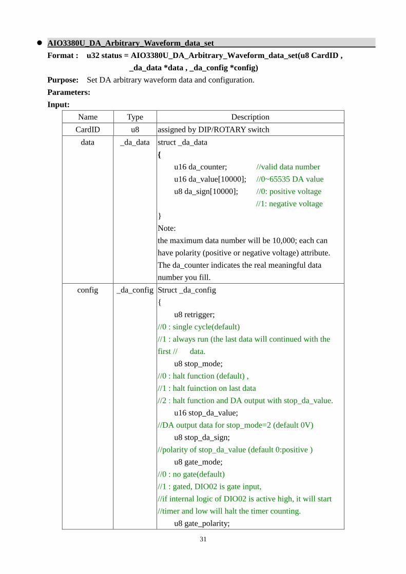
AIO3380U_DA_Arbitrary_Waveform_data_set
Format : u32 status = AIO3380U_DA_Arbitrary_Waveform_data_set(u8 CardID ,
_da_data *data , _da_config *config)
Purpose: Set DA arbitrary waveform data and configuration.
Parameters:
Input:
Name Type Description
CardID u8 assigned by DIP/ROTARY switch
data _da_data struct _da_data
{
u16 da_counter; //valid data number
u16 da_value[10000]; //0~65535 DA value
u8 da_sign[10000]; //0: positive voltage
//1: negative voltage
}
Note:
the maximum data number will be 10,000; each can
have polarity (positive or negative voltage) attribute.
The da_counter indicates the real meaningful data
number you fill.
config _da_config Struct _da_config
{
u8 retrigger;
//0 : single cycle(default)
//1 : always run (the last data will continued with the
first // data.
u8 stop_mode;
//0 : halt function (default) ,
//1 : halt fuinction on last data
//2 : halt function and DA output with stop_da_value.
u16 stop_da_value;
//DA output data for stop_mode=2 (default 0V)
u8 stop_da_sign;
//polarity of stop_da_value (default 0:positive )
u8 gate_mode;
//0 : no gate(default)
//1 : gated, DIO02 is gate input,
//if internal logic of DIO02 is active high, it will start
//timer and low will halt the timer counting.
u8 gate_polarity;

32
u32 timer;
// DAoutput sample time on
//time base 1us, timer constant no less than 100
}
Note:
1. The arbitrary waveform function will use timer0 as function time base. You cannot use timer0
during the arbitrary waveform function working.
2. Timer constant needs a value no less than100 (us) to avoid system performance lag.
3. DA0 is the dedicated output of waveform.
AIO3380U_DA_Arbitrary_Waveform_data_read
Format : u32 status = AIO3380U_DA_Arbitrary_Waveform_data_read(u8 CardID ,
_da_data *data , _da_config *config)
Purpose: Read DA arbitrary waveform data and configuration.
Parameters:
Input:
Name Type Description
CardID u8 assigned by DIP/ROTARY switch
Output:
Name Type Description
data _da_data struct _da_data
{
u16 da_counter; //valid data number
u16 da_value[10000]; //0~65535 DA value
u8 da_sign[10000]; //0: positive voltage
//1: negative voltage
}
Note:
the maximum data number will be 10,000; each can have
polarity (positive or negative voltage) attribute.
The da_counter indicates the real meaningful data number
you fill.
config _da_config Struct _da_config
{
u8 retrigger;
//0 : single cycle(default)
//1 : always run (the last data will continued with the first //
data.
u8 stop_mode;
//0 : halt function (default) ,

33
//1 : halt fuinction on last data
//2 : halt function and DA output with stop_da_value.
u16 stop_da_value;
//DA output data for stop_mode=2 (default 0V)
u8 stop_da_sign;
//polarity of stop_da_value (default 0:positive )
u8 gate_mode;
//0 : no gate(default)
//1 : gated, DIO02 is gate input,
//if internal logic of DIO02 is active high, it will start
//timer and low will halt the timer counting.
u8 gate_polarity;
u32 timer;
// DAoutput sample time on
//time base 1us, timer constant no less than 100
}
AIO3380U_DA_Arbitrary_Waveform_Start
Format : u32 status = AIO3380U_DA_Arbitrary_Waveform_Start(u8 CardID)
Purpose: DA arbitrary waveform output starts.
Parameters:
Input:
Name Type Description
CardID u8 assigned by jumper setting
Note: DA arbitrary waveform output starts means output the waveform from the first data stored.
AIO3380U_DA_Arbitrary_Waveform_Stop
Format : u32 status = AIO3380U_DA_Arbitrary_Waveform_Stop(u8 CardID)
Purpose: DA arbitrary waveform output stops.
Parameters:
Input:
Name Type Description
CardID u8 assigned by jumper setting
Note: DA arbitrary waveform output stops will depends on the configuration of stop_mode set.

34
8.4 TTL I/O Port R/W
In general, TTL I/O port can be input or output as configured. To work as input, the AIO3380U
series cards provides input digital debounce function.
Debounce is the function to filter the input jitters. From the microscope view of a switch input, you
will see the contact does not come to close or release to open clearly. In most cases, it will
contact-release-contact-release… for many times then go to steady state (ON or OFF). If you do not
have the debounce function, you will read the input at high state and then next read will get low state,
this maybe an error data for your decision of contact input.
Debounce can be implemented by hardware or software. Analog hardware debounce circuit will
have fixed time constant to filter out the significant input signal, if you want to change the response time;
the only way is to change the circuit device.
If digital debounce is implemented, maybe several filter frequency you can choose. To choose the
filter frequency, please keep the Nyquist–Shannon sampling theorem in mind: filter sample frequency
must at least twice of the input frequency. The following sample is a bad selection of debounce filter,
the input frequency is not as low as les than half of the sample frequency and the output will generate a
beat frequency.
<- Input frequency at 835Hz
<- Output of digital filter,
Please note the beat frequency.
Digital debounce circuit work at 1KHZ sample rate and observe the output of filter from 835Hz input.
Software debounce will consumes the CPU time a lot, we do not recommend to use except for you
really know you want.
35
To configure the port as input or output by:
AIO3380U_TTL_IO_config_set ( ) and read back the configuration by:
AIO3380U_TTL_IO_config_read ( ).
The TTL I/O port can use:
AIO3380U_TTL_IO_port_set ( ) to output data and input data by:
AIO3380U_TTL_IO_port_read( ).
For the point output, use:
AIO3380U_TTL_IO_point_set ( ) and point input by:
AIO3380U_TTL_IO_point_read ( ).
At noisy environment to debounce the signal or to debounce the mechanical contact input, use:
AIO3380U_TTL_IO_debounce_time_set ( ) to set the adequate time constant to drop out the
noise and read back to check the setting by:
AIO3380U_TTL_IO_debounce_time_read( ).
AIO3380U_TTL_IO_config_set
Format : u32 status =AIO3380U_TTL_IO_config_set (u8 CardID, u8 port,
u8 configuration)
Purpose: Sets port configuration.
Parameters:
Input:
Name Type Description
CardID u8 assigned by Rotary SW
port u8 port number
0: port0 (DIO0x)
1: port1 (DIO1x)
configuration u8 0: input port (default)
1: output port

36
AIO3380U_TTL_IO_config_read
Format : u32 status =AIO3380U_TTL_IO_config_read (u8 CardID, u8 port,
u8 *configuration)
Purpose: read port configuration.
Parameters:
Input:
Name Type Description
CardID u8 assigned by Rotary SW
port u8 port number
0: port0 (DIO0x)
1: port1 (DIO1x)
Output:
Name Type Description
configuration u8 0: input port (default)
1: output port
AIO3380U_TTL_IO_port_set
Format : u32 status = AIO3380U_TTL_IO_port_set (u8 CardID,u8 port, u8 data)
Purpose: Sets the port data.
Parameters:
Input:
Name Type Description
CardID u8 assigned by Rotary SW
port u8 port number
0: port0 (DIO0x)
1: port1 (DIO1x)
data u8 bitmap of output values
bit0: DIOn0
…
bit7: DIOn7

37
AIO3380U_TTL_IO_port_read
Format : u32 status = AIO3380U_TTL_IO_port_read (u8 CardID , u8 port , u8 *data)
Purpose: Read the port data.
Parameters:
Input:
Name Type Description
CardID u8 assigned by Rotary SW
port u8 port number
0: port0 (DIO0x)
1: port1 (DIO1x)
Output:
Name Type Description
data u8 bitmap of output/input values
bit0: DIOn0
…
bit7: DIOn7
AIO3380U_TTL_IO_point_set
Format : u32 status =AIO3380U_TTL_IO_point_set (u8 CardID, u8 port, u8 point,
u8 state)
Purpose: Sets the bit data of output port.
Parameters:
Input:
Name Type Description
CardID u8 assigned by Rotary SW
port u8 port number
0: port0 (DIO0x)
1: port1 (DIO1x)
point u8 point number
0~7 for bit0~bit7 (DIOn0 ~ DIOn7)
state u8 point of output state

38
AIO3380U_TTL_IO_point_read
Format : u32 status = AIO3380U_TTL_IO_point_read (u8 CardID, u8 port, u8 point,
u8 *state)
Purpose: Read the output port state .
Parameters:
Input:
Name Type Description
CardID u8 assigned by Rotary SW
port u8 port number
0: port0 (DIO0x)
1: port1 (DIO1x)
point u8 point number of input
0~7 for bit0~bit7 (DIOn0 ~ DIOn7)
Output:
Name Type Description
state u8 point of output/input state
AIO3380U_TTL_IO_debounce_time_set
Format : u32 status = AIO3380U_TTL_IO_debounce_time_set (u8 CardID,u8 port ,
u8 debounce_time)
Purpose: debounce time of the TTL I/O port signal
Parameters:
Input:
Name Type Description
CardID u8 assigned by Rotary SW
port u8 port number
0: port0 (DIO0x)
1: port1 (DIO1x)
debounce_time u8 Debounce time selection:
0: no debounce
1: filter out duration less than 10ms
(100Hz, default)
2: filter out duration less than 5ms
(200Hz)
3: filter out duration less than 1ms
(1KHZ)
Note: only valid for port configured as input

39
AIO3380U_TTL_IO_debounce_time_read
Format : u32 status = AIO3380U_TTL_IO_debounce_time_read (u8 CardID,u8 port ,
u8 *debounce_time)
Purpose: To read back configuration of debounce mode
Parameters:
Input:
Name Type Description
CardID u8 assigned by Rotary SW
port u8 port number
0: port0 (DIO0x)
1: port1 (DIO1x)
Output:
Name Type Description
debounce_time u8 Debounce time selection:
0: no debounce
1: filter out duration less than 10ms
(default)
2: filter out duration less than 5ms
3: filter out duration less than 1ms

40
8.5 Counter / Timer / PWM function
Many control applications need timer as time base for digital sampled data control systems. The
timer consists a counter to count the time base clock on the fly and generate interrupt on a periodic time
interval. If the counter do not count the time base but count the signals from external world, we call it
“counter”.
A timer/counter may be multi-functions, if the input signal and control mode and the output can be
programmed as various kind of working mode.
Input signal debounce
The timer / counter input comes from DIO00 ~ DIO03 the signal maybe occasionally contaminated
by noise. AIO3380U series card provides wide range of filter frequency from 100Hz up to 1KHz (to
drop out noise pulse less than 1ms), even the quadrature signals comes from mechanical contacts the
counter can still operate very nice. If you will use faster signals, you can program the debounce as no
debounce to pass the signal directly to counter. But take care of the noise induced by the environment
and wiring, we recommended you to use a high speed isolation type encoder counter card such as
LSI3101 (up to 8M counter speed) or LSI3101A (up to 16M counter speed) of JS Automation Corp to
get better performance.
Timer function
The timer model used in AIO3380U series is as follows:
Ti_modecounter
0: NO gate1: gated 2: edge start
0: one cycle1: auto reload
retrigger_mode
To_mode
0:NO TOUT1:Out Pulse (out_width effective)2:Out level 4:Out toggle
Gate Tout
polaritypolarity
DIO02DIO03
DIO10DIO11
In this model, the timer can work in one cycle mode and auto reload mode.
one cycle mode: the timer will stop when the timer time up.
auto reload mode ( sometimes called continuous mode): the time will reload the time constant
while time up.
In the timer input control block:
NO gate: the timer do not control by any input.
gated : the timer only working on the gate input active and stops counting while gate is inactive.
timer on timer onoff off
Gate
Edge start: the timer will start timing while the gate input transition from inactive to active.

41
Gate
timer on
In the timer output block:
NO TOUT: the timer has no output to control (but timer time up interrupt is available).
Out_pulse: while the timer time up, it will trigger an output pulse and pulse width is controlled by
out_width register at 1us time base.
output
time uptime up
out width out width
Out_level: while the timer time up, it will trigger the output active.
output
time uptime up
Out_toggle: while the timer time up, it will trigger the output toggled.
output
time up time up time up
polarity: set the input/output active high or active low
Counter function
The counter model used in AIO3380U series is as follows:
counter
0: one cycle1: auto reload
retrigger_mode
To_mode
Software decrement
0:NO TOUT1:Out Pulse (out_width effective)2:Out level 4:Out toggle
Ti_mode
0: NO gate1: gated 2: edge start
Gate
Ti
Tout
polarity
polarity
polarity
DIO10DIO11
DIO02DIO03
DIO00DIO01
In this model, the counter can work in one cycle mode and auto reload mode.
one cycle mode: the counter will stop when the counter cross zero.
auto reload mode ( sometimes called continuous mode): the counter will reload the counter
constant while time up.
Software decrement: the counter value will decrement by software trigger.
In the counter input control block:
NO gate: the counter do not control by any input.

42
gated : while gate input is active and the counter signal input also active the counter will decrement
by 1 and stops counting while gate is inactive.
Take the following diagram as example, the counter is initialized at 5 and working in gated mode,
while the Ti (counter signal input) is active and gate is also active, the counter will decrease by one.
off offcounter on counter on
Ti
5 344 2 1countervalue
Gate
Edge start: the counter will start counting function while the gate input transition from inactive to
active.
Gate
counter on
In the counter output block: (refer the timer function)
NO TOUT: the counter has no output to control (but counter cross zero interrupt is available).
Out_pulse: while the counter cross zero, it will trigger a output pulse and pulse width is controlled
by out_width register at 1us time base.
Out_level: while the counter cross zero, it will trigger the output active.
Out_toggle: while the counter cross zero, it will trigger the output toggled.
polarity: set the input/output active high or active low
PWM function
The PWM model used in AIO3380U series is as follows:
Ti_mode
0: NO gate1: gated 2: edge start
To_mode
0:NO TOUT4:Out toggle
PWMfrequency counter
PWMduty counter
PWM frequency PWM frequency
Gate Tout
polarity polarity
DIO02DIO03
DIO10DIO11
PWM dutyPWM duty
In this model, the PWM counter can only work in auto reload mode.
auto reload mode ( sometimes called continuous mode): the time will reload the time constant
while time up.
In the PWM counter input control block: (refer the counter function)
NO gate: the PWM counter do not control by any input.

43
gated : while gate input is active the PWM counter will start working and stops while gate is
inactive.
Edge start: the PWM counter will start counting function while the gate input transition from
inactive to active.
In the PWM counter output block: (refer the timer function)
NO TOUT: the PWM counter has no output to control.
Out_toggle: while the PWM counter cross zero, it will trigger the output toggled.
polarity: set the input/output active high or active low
quadrature encoder counter
In spite of the flexible multi-function timer/counter, the quadrature encoder counter is another type
of application. The AIO3380U series also has the build in function for quadrature encoder input
counting.
digital debounce
digital debounce
Multiple rate
UP/DOWNcounter
A
B
DIO00DIO01
DIO02DIO03
On the above diagram, you can see the digital debounce function filter out the unwanted high
frequency then pass the signal to the multiple rate circuit to determine the pulse and direction, finally the
counter counts the pulses.
A phase
B phase
x 4 pulse
x 2 pulse
x 1 pulse
The left diagram shown that A phase
leads B, if we take A leads B as
up count and the counting
pulse of up count will depends
on the multiple rate.
DLL functions of timer / counter
Timer/counter function can work in general mode: as timer, as counter or as PWM generator and in
special mode: quadrature counter mode.
In the general timer/counter mode, DIO00, DIO02 and DIO10 can be configured as dedicated I/O
for timer1 / counter1 and DIO01, DIO03 and DIO11 can be configured as dedicated I/O for timer2 /
44
counter2.
To configure the working mode use
AIO3380U_timer_set( ) to configure as timer and its output mode
AIO3380U_counter_set( ) to configure as counter and its input and output mode
AIO3380U_PWM_set( ) to configure as PWM generator.
AIO3380U_quadrature_set( ) to configure as quadrature counter.
To start/stop the operation by:
AIO3380U_TC_start( )
AIO3380U_TC_stop( )
To read or load dedicated timer/counter registers, use
AIO3380U_TC_set( ) set TC dedicated registers
AIO3380U_TC_read( ) read TC dedicated registers
If you want to change the input polarity, using
AIO3380U_TC_input_polarity_set( ) and read back to verify by:
AIO3380U_TC_input_polarity_read( )
If you want to change the output polarity, using
AIO3380U_TC_output_polarity_set( ) and read back to verify by:
AIO3380U_TC_output_polarity_read( )

45
AIO3380U_timer_set
Format : u32 status = AIO3380U_timer_set (u8 CardID, u8 TimerID,
Timer_struct *TC_struct)
Purpose: To setup timer operation mode or update timer
Parameters:
Input:
Name Type Description
CardID u8 assigned by DIP/ROTARY switch
TimerID u8 0: timer/counter0
1: timer/counter1
TC_struct struct struct TC_struct
{
u8 TiGate_MODE,
// 0: NO_GATE
//Always count without gate function,
//DIO02 / DIO03 is digital input.
// 1:GATED
//DIO02 / DIO03 is gate input,
//after command start_TC,
//if internal logic active high will start timer and
//low will halt the timer counting.
// 2: EDGE_START
//DIO02 / DIO03 is gate input,
//after command start_TC,
//if internal logic active high will start timer
u32 time_constant,
// Timer constant based on 1us clock
u8 Tout_mode,
// 0: NO_TOUT ,
// DIO10 / DIO11: use as general digital output
// 1: OUT_PULSE
//DIO10 / DIO11: timer cross zero output pulse.
//(out_width effective)
// 2: OUT_LEVEL
//DIO10 / DIO11: timer cross zero output will //make.
// 4:OUT_TOGGLE
//DIO10 / DIO11: timer cross zero toggles output

46
u16 Tout_width,
// Output pulse width based on 1us clock, only
//valid in Tout_mode is OUT_PULSE
u8 cont_single,
// 0: SINGLE_CYCLE
//single cycle mode, timer will stop operation
//when time constant count down to zero.
// 1: ALWAYS_RUN
//continuous operation mode, timer will reload
//time constant and continue operation when
//time constant count down to zero.
}

47
AIO3380U_counter_set
Format : u32 status = AIO3380U_counter_set (u8 CardID, u8 TimerID,
Counter_struct *TC_struct)
Purpose: To setup counter operation mode or update counter
Parameters:
Input:
Name Type Description
CardID u8 assigned by DIP/ROTARY switch
TimerID u8 0: timer/counter0
1: timer/counter1
TC_struct struct struct TC_struct
{
u8 TiGate_MODE,
// 0: NO_GATE
//Always count without gate function,
//Timer/counter0, Timer/counter1:
//DIO00, DIO01 is counter pulse input
//DIO02, DIO03 is digital input.
// 1:GATED
//DIO00, DIO01 is counter pulse input (Ti)
//DIO02, DIO03 is gate input, internal logic active
//high will pass the counter Ti pulse to counter //after
command start_TC
// 2: EDGE_START
//DIO00, DIO01 is counter pulse input (Ti)
//DIO02, DIO03 is gate input, internal logic active
//high will start topass the counter Ti pulse to //counter
after command start_TC
u32 counter_constant,
// Counter constant
u8 Tout_mode,
// 0: NO_TOUT
// Timer/counter0, Timer/counter1:
// OUT10, OUT11 use as general digital output
// 1: OUT_PULSE

48
//OUT10, OUT11: timer cross zero output pulse.
//(out_width effective)
// 2: OUT_LEVEL
//OUT10, OUT11: timer cross zero output will //make.
// 4:OUT_TOGGLE
//OUT10, OUT11: timer cross zero toggles output
u16 Tout_width,
// Output pulse width based on 1us clock, only
//valid in Tout_mode is OUT_PULSE
u8 cont_single
// 0: SINGLE_CYCLE
//single cycle mode, counter will stop operation //when
time constant count down to zero.
// 1: ALWAYS_RUN
// continuous operation mode, counter will reload //time
constant and continue operation when time //constant
count down to zero.
}

49
AIO3380U_PWM_set
Format : u32 status = AIO3380U_PWM_set(u8 CardID, u8 TimerID,
PWM_struct *PWM_struct)
Purpose: To setup PWM operation mode or update PWM.
Parameters:
Input:
Name Type Description
CardID u8 assigned by DIP/ROTARY switch
TimerID u8 0: timer/counter0
1: timer/counter1
PWM_struct struct PWM_struct
{
u8 TiGate_MODE,
// 0: NO_GATE
//Always count without gate function,
//Timer/counter0, Timer/counter1:
//DIO00, DIO01 is counter pulse input
//DIO02, DIO03 is digital input.
// 1:GATED
//DIO00, DIO01 is counter pulse input (Ti)
//DIO02, DIO03 is gate input, internal logic active
//high will pass the counter Ti pulse to counter
//after command start_TC
u16 PWM_freq;
// PWM frequency clock count based on 33MHz
// clock
u16 PWM_duty;
//PWM duty clock count based on 33MHz clock
//OUT10, OUT11 use as PWM output
}
Note:
1. PWM base clock is based on33MHz, say if you want your PWM frequency is 20KHz, please put
the PWM_freq = (33MHz/20KHz) = 1650
2. PWM duty must less than PWM_freq for proper operation, from the example above, the
PWM_duty value can be 1 ~ 1649. For 50% duty, the PWM_duty will be 1650/2 = 825

50
AIO3380U_quadrature_set
Format : u32 status = AIO3380U_quadrature_set (u8 CardID,u8 TimerID,
u8 Multiple_rate)
Purpose: To setup quadrature counter operation mode
Parameters:
Input:
Name Type Description
CardID u8 assigned by DIP/ROTARY switch
TimerID u8 0: timer/counter0
1: timer/counter1
Multiple_rate u8 Only valid for quadrature mode, in other mode, this
parameter is ignored.
0: MULTIPLE_4 (default)
A,B phase input multiple rate is 4
1: MULTIPLE_2
A,B phase input multiple rate is 2
2: MULTIPLE_1
A,B phase input multiple rate is 1
AIO3380U_TC_start
Format : u32 status = AIO3380U_TC_start (u8 CardID,u8 TimerID)
Purpose: To start timer/counter/PWM/quadrature counter operation mode
Parameters:
Input:
Name Type Description
CardID u8 assigned by DIP/ROTARY switch
TimerID u8 0: timer/counter0
1: timer/counter1
AIO3380U_TC_stop
Format : u32 status = AIO3380U_TC_stop (u8 CardID, u8 TimerID)
Purpose: To stop timer/counter/PWM/quadrature counter operation mode
Parameters:
Input:
Name Type Description
CardID u8 assigned by DIP/ROTARY switch
TimerID u8 0: timer/counter0
1: timer/counter1
51
AIO3380U_TC_set
Format : u32 status=AIO3380U_TC_set (u8 CardID, u8 TimerID, u8 index, u32 data)
Purpose: To set data to counter/timer register
Parameters:
Input:
Name Type Description
CardID u8 assigned by DIP/ROTARY SW
TimerID u8 0: timer/counter0
1: timer/counter1
index u8 0: TC_CONTROL
1: TC_MODE
2: TiGate_MODE
3: To_MODE
4: RETRIGGER_MODE
5: PRELOAD
6: COUNTER
7:OUT_WIDTH
8: MULTIPLE_RATE
data u32 register data to be set
Note:
1. please refer the next segment “Note: Meaning of setting or return value of different index”
2. Write to IRQ_STATUS will reset the corresponding bit. Say, if write with bit0=1, the status bit0
will reset but other bit will not effect.

52
AIO3380U_TC_read
Format : u32 status=AIO3380U_TC_read (u8 CardID, u8 TimerID, u8 index,u32 *data)
Purpose: To read data from counter/timer
Parameters:
Input:
Name Type Description
CardID u8 assigned by DIP/ROTARY SW
TimerID u8 0: timer/counter0
1: timer/counter1
index u8 0: TC_CONTROL
1: TC_MODE
2: TiGate_MODE
3: Tout_MODE
4: RETRIGGER_MODE
5: PRELOAD
6: COUNTER
7:OUT_WIDTH
8: MULTIPLE_RATE
Output:
Name Type Description
data u32 Data read back
Note: Meaning of setting or return value of different index

53
index register value meaning
0 TC_CONTROL 0 STOP, stop operation of TC
1 START, start operation of TC
1 TC_MODE 0 TIMER_MODE
1 COUNTER_MODE
3 SW_DEC (a write will software decrease
counter by 1 and return to
COUNTER_MODE.)
4 PWM_MODE
8 QUADRATURE_MODE
2 TiGate_MODE 0 NO_GATE
1 GATED
2 EDGE_START
3 Tout_MODE 0 NO_TOUT
1 OUT_PULSE
2 OUT_LEVEL
4 OUT_TOGGLE
4 RETRIGGER_MODE 0 SINGLE_CYCLE
1 ALWAYS_RUN
5 PRELOAD 1~0xffffffff Counter or timer or PWM preload value
6 COUNTER 1~0xffffffff Set (write): will write preload and counter
Read : will read counter on the fly
7 OUT_WIDTH 1~0xffff Output pulse width based on 1us
8 MULTIPLE_RATE 0 0: MULTIPLE_4 (default)
A,B phase input multiple rate is 4
1 1: MULTIPLE_2
A,B phase input multiple rate is 2
2 2: MULTIPLE_1
A,B phase input multiple rate is 1

54
AIO3380U_TC_input_polarity_set
Format : u32 status = AIO3380U_TC_input_polarity_set (u8 CardID,u8 TimerID,
u8 input,u8 polarity)
Purpose: Set TC input polarity.
Parameters:
Input:
Name Type Description
CardID u8 assigned by DIP/ROTARY SW
TimerID u8 timer/counter designation
0: timer/counter0
1: timer/counter1
input u8 input:
0: Gate.
1: Ti (clock input).
polarity u8 polarity values:
0: means normal.
1: means invert.
Note: timer/counter0, Port 0,bit 0 clock input , bit 2 gate input.
timer/counter1, Port 0,bit 1 clock input , bit 3 gate input.
AIO3380U_TC_input_polarity_read
Format : u32 status = AIO3380U_TC_input_polarity_read (u8 CardID,u8 TimerID,
u8 input,u8 *polarity)
Purpose: Read TC input polarity.
Parameters:
Input:
Name Type Description
CardID u8 assigned by DIP/ROTARY SW
TimerID u8 timer/counter designation
0: timer/counter0
1: timer/counter1
input u8 input:
0: Gate.
1: Ti (clock input).
Output:
Name Type Description
polarity u8 polarity values:
0: means normal.
1: means invert.

55
AIO3380U_TC_output_polarity_set
Format : u32 status = AIO3380U_TC_output_polarity_set (u8 CardID,u8 TimerID,
u8 polarity)
Purpose: Set TC output polarity
Parameters:
Input:
Name Type Description
CardID u8 assigned by DIP/ROTARY SW
TimerID u8 timer/counter designation
0: timer/counter0
1: timer/counter1
polarity u8 TC output polarity:
0: means normal
1: means invert
Note:
timer/counter0, Port 1,bit 0 Signal output.
timer/counter1, Port 1,bit 1 Signal output.
AIO3380U_TC_output_polarity_read
Format : u32 status = AIO3380U_TC_output_polarity_read (u8 CardID,u8 TimerID,
u8 * polarity)
Purpose: Read TC output polarity
Parameters:
Input:
Name Type Description
CardID u8 assigned by DIP/ROTARY SW
TimerID u8 timer/counter designation
0: timer/counter0
1: timer/counter1
Output:
Name Type Description
polarity u8 TC output polarity:
0: means normal
1: means invert

56
8.6 Interrupt function
Interrupt is a efficient method to quick response without occupy too much system resource.
AIO3380U provide timer/counter and TTL port0 as interrupt source, to use interrupt function use
AIO3380U_IRQ_link_process( ) to link your irq service routine,
AIO3380U_IRQ_enable ( ) to enable it and
AIO3380U_IRQ_disable ( ) to disable it.
AIO3380U_IRQ_mask_set() to mask off the undesired source;
AIO3380U_IRQ_mask_read( ) to read back for verify the mask setting
AIO3380U_IRQ_IO_polarity_set( ) to set the polarity of port0 IRQ generation.
AIO3380U_IRQ_IO_polarity_read( ) to read back for verifying.
After you enable and link interrupt, you can enable/disable timer/counter function or enable/disable
interrupt function as you need.
To check the irq status
AIO3380U _IRQ_status_read ( ) will do.
AIO3380U_IRQ_link_process
Format : u32 status = AIO3380U_IRQ_link_process(u8 CardID,
void (__stdcall *callbackAddr(u8 CardID))
Purpose: To link the interrupt source with the callback function.
Parameters:
Input:
Name Type Description
CardID u8 assigned by DIP/ROTARY SW
callbackAddr void the address of your callback function
AIO3380U_IRQ_enable
Format : u32 status = AIO3380U_IRQ_enable (u8 CardID,HANDLE *phEvent)
Purpose: Enable interrupt.
Parameters:
Input:
Name Type Description
CardID u8 assigned by DIP/ROTARY SW
Output:
Name Type Description
phEvent HANDLE The returned handle of event
57
AIO3380U_IRQ_disable
Format : u32 status = AIO3380U_IRQ_disable (u8 CardID)
Purpose: To disable interrupt.
Parameters:
Input:
Name Type Description
CardID u8 assigned by DIP/ROTARY SW
AIO3380U_IRQ_mask_set
Format : u32 status = AIO3380U_IRQ_mask_set(u8 CardID,u16 mask)
Purpose: Set IRQ mask.
Parameters:
Input:
Name Type Description
CardID u8 assigned by DIP/ROTARY SW
mask u16 b0:
0, disable DIO00 as interrupt source
1, enable DIO00 as interrupt source
…
b6:
0, disable DIO06 as interrupt source
1, enable DIO06 as interrupt source
b7:
0, disable DIO07 as interrupt source
1, enable DIO07 as interrupt source
b8:
0, disable TC0 counter counts to zero as
interrupt source
1, enable TC0 counter counts to zero as
interrupt source
b9:
0, disable TC1 counter counts to zero as
interrupt source
1, enable TC1 counter counts to zero as
interrupt source

58
AIO3380U_IRQ_mask_read
Format : u32 status = AIO3380U_IRQ_mask_read(u8 CardID,u16 *mask)
Purpose: Read IRQ mask.
Parameters:
Input:
Name Type Description
CardID u8 assigned by DIP/ROTARY SW
Output:
Name Type Description
mask u16 b0:
0, disable DIO00 as interrupt source
1, enable DIO00 as interrupt source
…
b6:
0, disable DIO06 as interrupt source
1, enable DIO06 as interrupt source
b7:
0, disable DIO07 as interrupt source
1, enable DIO07 as interrupt source
b8:
0, disable TC0 counter counts to zero as
interrupt source
1, enable TC0 counter counts to zero as
interrupt source
b9:
0, disable TC1 counter counts to zero as
interrupt source
1, enable TC1 counter counts to zero as
interrupt source

59
AIO3380U_IRQ_IO_polarity_set
Format : u32 status =AIO3380U_IRQ_IO_polarity_set (u8 CardID, u8 polarity)
Purpose: Sets the I/O polarity of TTL port0
Parameters:
Input:
Name Type Description
CardID u8 assigned by Rotary SW
polarity u8 port0 polarity values:
0: any bit of port0 form low to high (default)
can generate IRQ
1: any bit of port0 from high to low can
generate IRQ
AIO3380U_IRQ_IO_polarity_read
Format : u32 status = AIO3380U_IRQ_IO_polarity_read (u8 CardID, u8 * polarity)
Purpose: Read the I/O IRQ polarity of the TTL port0.
Parameters:
Input:
Name Type Description
CardID u8 assigned by Rotary SW
Output:
Name Type Description
polarity u8 port0 polarity values:
0: any bit of port0 form low to high(default)
can generate IRQ
1: any bit of port0 from high to low can
generate IRQ

60
AIO3380U_IRQ_status_read
Format : u32 status = AIO3380U_IRQ_status_read(u8 CardID,u16 * status)
Purpose: To read IRQ state
Parameters:
Input:
Name Type Description
CardID u8 assigned by DIP/ROTARY SW
Output:
Name Type Description
status u16 Bit 0: DIO00 generate IRQ.
…
Bit 7: DIO07 generate IRQ.
Bit 8: timer/counter0 generate IRQ.
Bit 9: timer/counter1 generate IRQ.
Note: This command will also clear the on board IRQ_status register, the second read will not be
correct.

61
8.7 Security function
From the dll version 2.0 and later, we remove the software key function owing to some
customers complained about the card locked on some unknown occasion. We only remain the
functions to comply with the existing programs but the returned value always true.
Since AIO3380U is a general purpose card, anyone who can buy from JS automation corp. or her
distributors. Your program is the fruit of your intelligence, un-authorized copy maybe prevent by the
security function enabled.
You can use
AIO3380U_password_set( ) to set password and start the security function. Use
AIO3380U_password_change( ) to change it.
If you don’t want to use security function after the password being setup,
AIO3380U_password_clear( ) will reset to the virgin state.
Once the password is set, any function call of the dll’s (except for the security functions) will be
blocked until the
AIO3380U_security_unlock( ) unlock the security.
You can also use
AIO3380U_security_status_read( ) to check the current status of security.
AIO3380U_password_set
Format : u32 status = AIO3380U_password_set(u8 CardID,u16 password[5])
Purpose: To set password and if the password is not all “0”, security function will be enabled.
Note: If the password is all “0”, the security function is disabled.
Parameters:
Input:
Name Type Description
CardID u8 assigned by DIP/ROTARY SW
password[5] u16 Password, 5 words
AIO3380U_password_change
Format : u32 status = AIO3380U_password_change(u8 CardID,u16 Oldpassword[5],
u16 password[5])
Purpose: To replace old password with new password.
Parameters:
Input:
Name Type Description
CardID u8 assigned by DIP/ROTARY SW
Oldpassword
[5]
u16 The previous password
password[5] u16 The new password to be set

62
AIO3380U_password_clear
Format : u32 status = AIO3380U_password_clear(u8 CardID,u16 password[5])
Purpose: To clear password, to set password to all “0”, i.e. disable security function.
Parameters:
Input:
Name Type Description
CardID u8 assigned by DIP/ROTARY SW
password[5] u16 The password previous set
AIO3380U_security_unlock
Format : u32 status = AIO3380U_security_unlock(u8 CardID,u16 password[5])
Purpose: To unlock security function and enable the further operation of this card
Parameters:
Input:
Name Type Description
CardID u8 assigned by DIP/ROTARY SW
password[5] u16 The password previous set
AIO3380U_security_status_read
Format : u32 status = AIO3380U_security_status_read(u8 CardID,u8 *lock_status,
u8 *security_enable )
Purpose: To read security status for checking if the card security function is unlocked.
Parameters:
Input:
Name Type Description
CardID u8 assigned by DIP/ROTARY SW
Output:
Name Type Description
lock_status u8 0: security unlocked
1: locked
2: dead lock (must return to original
maker to unlock)
security_ena
ble
u8 0: security function disabled
1: security function enabled

63
8.8 Error conditions
These error types may indicate an internal hardware problem on the board. Error Codes summary
contains a detailed listing of the error status returned by AIO3380U functions.
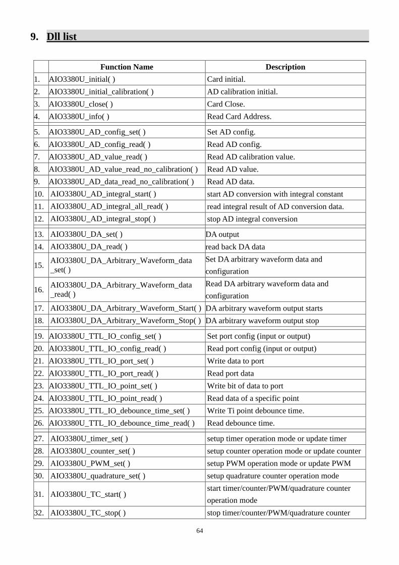
64
9. Dll list
Function Name Description
1. AIO3380U_initial( ) Card initial.
2. AIO3380U_initial_calibration( ) AD calibration initial.
3. AIO3380U_close( ) Card Close.
4. AIO3380U_info( ) Read Card Address.
5. AIO3380U_AD_config_set( ) Set AD config.
6. AIO3380U_AD_config_read( ) Read AD config.
7. AIO3380U_AD_value_read( ) Read AD calibration value.
8. AIO3380U_AD_value_read_no_calibration( ) Read AD value.
9. AIO3380U_AD_data_read_no_calibration( ) Read AD data.
10. AIO3380U_AD_integral_start( ) start AD conversion with integral constant
11. AIO3380U_AD_integral_all_read( ) read integral result of AD conversion data.
12. AIO3380U_AD_integral_stop( ) stop AD integral conversion
\ 13. AIO3380U_DA_set( ) DA output
14. AIO3380U_DA_read( ) read back DA data
15. AIO3380U_DA_Arbitrary_Waveform_data
_set( )
Set DA arbitrary waveform data and
configuration
16. AIO3380U_DA_Arbitrary_Waveform_data
_read( )
Read DA arbitrary waveform data and
configuration
17. AIO3380U_DA_Arbitrary_Waveform_Start( ) DA arbitrary waveform output starts
18. AIO3380U_DA_Arbitrary_Waveform_Stop( ) DA arbitrary waveform output stop
\ 19. AIO3380U_TTL_IO_config_set( ) Set port config (input or output)
20. AIO3380U_TTL_IO_config_read( ) Read port config (input or output)
21. AIO3380U_TTL_IO_port_set( ) Write data to port
22. AIO3380U_TTL_IO_port_read( ) Read port data
23. AIO3380U_TTL_IO_point_set( ) Write bit of data to port
24. AIO3380U_TTL_IO_point_read( ) Read data of a specific point
25. AIO3380U_TTL_IO_debounce_time_set( ) Write Ti point debounce time.
26. AIO3380U_TTL_IO_debounce_time_read( ) Read debounce time.
27. AIO3380U_timer_set( ) setup timer operation mode or update timer
28. AIO3380U_counter_set( ) setup counter operation mode or update counter
29. AIO3380U_PWM_set( ) setup PWM operation mode or update PWM
30. AIO3380U_quadrature_set( ) setup quadrature counter operation mode
31. AIO3380U_TC_start( ) start timer/counter/PWM/quadrature counter
operation mode
32. AIO3380U_TC_stop( ) stop timer/counter/PWM/quadrature counter

65
operation mode
33. AIO3380U_TC_set( ) set data to counter/timer register
34. AIO3380U_TC_read( ) read data from counter/timer register
35. AIO3380U_TC_input_polarity_set( ) Set TC input polarity
36. AIO3380U_TC_input_polarity_read( ) Read back TC input polarity setting
37. AIO3380U_TC_output_polarity_set( ) Set TC output polarity
38. AIO3380U_TC_output_polarity_read( ) Read back TC output polarity setting
39. AIO3380U_IRQ_link_process( ) Link process IRQ.
40. AIO3380U_IRQ_enable( ) Enable IRQ.
41. AIO3380U_IRQ_disable ( ) Disable IRQ.
42. AIO3380U_IRQ_mask_set( ) Set mask.
43. AIO3380U_IRQ_mask_read( ) Read mask.
44. AIO3380U_IRQ_IO_polarity_set( ) Set IO polarity.
45. AIO3380U_IRQ_IO_polarity_read( ) Read IO polarity.
46. AIO3380U_IRQ_status_read ( ) Read IRQ status.
47. AIO3380U_password_set( ) Set password
48. AIO3380U_password_change( ) Change password
49. AIO3380U_password_clear( ) Clear password
50. AIO3380U_security_unlock( ) Unlock security function
51. AIO3380U_security_status_read( ) Read security status

66
10. AIO3380U Error codes summary
10.1 AIO3380U Error codes table
Error
Code Symbolic Name Description
0 JSDRV_NO_ERROR Success, No error.
2 JSDRV_INIT_ERROR Driver initial error
3 JSDRV_UNLOCK_ERROR Security unclock failure
4 JSDRV_LOCK_COUNTER_ERROR Dead lock, unclock failure more than 10 times
5 SDRV_SET_SECURITY_ERROR Password overwrite error
100 DEVICE_RW_ERROR Device Read/Write error
101 JSDRV_NO_CARD No AIO3380U card on the system.
102 JSDRV_DUPLICATE_ID AIO3380U CardID duplicate error.
104 JSDRV_PAR_ERROR Bad parameter or illegal parameter
300 JSDIO_ID_ERROR Function input parameter error. CardID setting
error, CardID doesn’t match the DIP/ROTARY
SW setting
301 JSAIO_MODE_ERROR Mode parameter error.
Parameter out of range.
302 JSAIO_CHANNEL_ERROR Channel parameter error.
Parameter out of range.
305 JSAIO_CONVERSION_ERROR Conversion time over. Maybe no hardware or
bad hardware.
306 JSAIO_CONVERSION_BUSY A/D is busy in conversion
400 JSAIO_PORT_ERROR Port parameter error.
Parameter out of range.
401 JSAIO_STATE_ERROR State parameter error.
Parameter out of range.
402 JSAIO_POINT_ERROR Point parameter error.
Parameter out of range.
403 JSAIO_EEPROM_RW_ERROR Eeprom R/W error
405 JSAIO_CALIBRATION_ERROR Calibration error.
Maybe out of range.
406 JSAIO_TIMERID_ERROR TimerID parameter error.
Parameter out of range.
407 JSAIO_TO_MODE_ERROR To_mode parameter error.
Parameter out of range.
408 JSAIO_TI_MODE_ERROR Ti_mode parameter error.
Parameter out of range.
409 JSAIO_PARAMETER_ERROR Parameter error.

67
Parameter out of range.
500 JSAIO_EVENT_ERROR Event error.
Maybe no event created.


![DIGITALES FÜR MENSCHEN :data re port · 2020. 4. 16. · :data[re]port DIGITALES FÜR MENSCHEN _ 1. QUARTAL 2020 So sehen kreative Lösungen aus: Roboter auf dem Feld und Bildung](https://img.pdfslide.tips/doc/110x75/604a5822497b5b7fba59e0db/digitales-foer-menschen-data-re-port-2020-4-16-datareport-digitales-foer.jpg)