Embed Size (px)
Citation preview

Solid laser system
2015.02.19Mitsuhiro Yoshida

Properties of laser medium
LD Pump(808nm)
Nd:YVO4Nd:YAG
SHG(532nm) 40%FHG(266nm) 20%5HG(213nm) 3%
τ~ 200μs, 40%Nd-doped
Yb-doped
Ti-doped
LD Pump(941/976nm)
Yb-glassYb:YAGYb:BOYS
1064nm808nm
941/976nm 1040nm
τ~ 900μs, 40%
Pump(808nm)
Nd:YAG SHG40%
1064nm808nmTi:Sapphire
532nm 800nm
τ~ 3μs, 40%τ=200μs, 40%
○ 4-state laser is easy to operate.○ High power pump LD is available.○ Large crystal is available× Pulse width is determined by SESAM. (Gaussian)
○ Wide bandwidth => pulse shaping○ Long fluorescent time => High power○ Fiber laser oscillator => Stable○ Small state difference × ASE× Absorption
○ Very wide bandwidth○ High breakdown threshold× Low cross section× Short fluorescent time => Q-switched laser is required for pumping
Pump
TW laser is based on Ti-Sapphire
SHG(520nm) 40%FHG(260nm) 20%5HG(208nm) 3%
SHG(400nm) 40%THG(266nm) 20%FHG(200nm) 10%
Material Nd:YAG Yb:YAG Ti:Sapphire
Wavelength 1064nm 1030nm 660- 1100nm
Fluorescent time 230ms 960ms 3.2ms
Spectral width 0.67nm 9.5nm 440nm
Fourier minimumPulse width
2.48ps 165fs 2.59fs
Wavelength 807.5nm 941nm 488nm
Spectral width 1.5nm 21nm 200nm
Quantum efficiency 76% 91% 55%
Fluo
resc
ence
Abs
orpt
ion
Best for RF-Gun
Nd laser system for 3-2 RF-Gun
Ti:Sapphire laser system for beam monitor.

Yb-FiberFrontend
Superconitnuumbroadning
OPCPA
Yb:YAG Thin Disk
Laser schemes
Ti-SapphireOscillator
Ti-Sapphire
Oscillator
Many commertial product.- How to maintain continuously?- How to generate 2-bunch ?
Amplifier
Nd:YAG
CPA
Yb:BOYS, Yb:CaF2- Broadband
1030nm
Pump
940nm LD
Flash pumped
η ~ 0.5%
η ~ 40%
Material Nd:YAG Yb:YAG Ti:Sapphire
Wavelength 1064nm 1030nm 660-1100nm
Fluorescent time 230μs 960μs 3.2μs
Spectral width 0.67nm 9.5nm 440nm
Fourier minimumPulse width
2.48ps 165fs 2.59fs
Wavelength 807.5nm 941nm 488nm
Spectral width 1.5nm 21nm 200nm
Quantum efficiency 76% 91% 55%
Flu
ore
scen
ceA
bso
rpti
on
LD pumped
- Very high gain- Critical incident angle
- Fiber laser is stable in principle.- High efficiency (long fluorecense lifetime)- Low gain at room temperature => Lower temperature

Nd based solid laser(3-2 DAW RF-Gun)

Nd based laser system
• Nd:YVO4 oscillator + Nd:YAG multi-pass amplifier
30 ps (10 mm)

Nd based laser system (renewed)

発振器

増幅部

増幅部

波長変換部
Yb solid laser(A-1 RF-Gun)

Characteristics of Yb doped laser• Long fluorescent lifetime ~ 1ms• Wideband• High quantum efficiencyX Quasi-three level
=> Absorption at room temperatureX Small cross section
YbBase material
Stimulatedemission
cross section
[10-20cm2]
Fluorescence
lifetime[ms]
Thermalconductivity
[W/mK]
Fluorescencespectral width[nm]
Fourierminium
[fs]
Experimental recordsPulse width
[fs]
Average power
[W]
YAG 2 0.95 11 9 120
340 0.11
136 0.003
730 16
810 60
KYW 3 0.7 3.3 24 50 71 0.12
KGW 3 0.7 3.3 25 47112 0.2
176 1.1
glass 0.63 2 - 35 33 36 0.065
GdCOB 0.35 2.7 2.1 44 27 89 0.04
BOYS 0.2 2.5 1.8 60 1969 0.08
86 0.3
YVO4 - 1.2 - - - 61 0.054
CaCdAlO4 0.55 - 6.9 - - 47 0.038

Temperature dependence of Yb:YAG• Improvement of thermal and emission property
(Thermal lens effect) (Excitation density)
300K30kW/cm2
Pertier
GM+He
300K P/P0 = exp(g0z) ~ 2150K → g = 7 [cm-1]
10 W/m/K , dn/dT = 8ppm/K @ 300K25 W/m/K , dn/dT = 3ppm/K @ 150K ↑150K 1/6 Thermal lens
Same gain @ 1/3 excitation density → ↓
150K => 1/20 thermal lens

Yb:YAG thin disk Laser at room temperature
0
50
100
150
200
250
300
350
0 200 400 600 800 1000 1200 1400
Epump (mJ )Eou
t (m
J)
30% efficiency was achieved at room temperature Yb:YAG
Yb disk laser
940nm LD (2.4 kW / module)
Yb:YAG disk10 % doped 2mm thickness

Yb:YAG
• 10% dope, α=12/cm, 5kW/cm2, 25Hz
0.5t 1t

How to generate 2-bunch• Amplification time of standard regenerative amplifier
(usually adopted in commertial product) is around 1 ms.
• Two regenerative amplifier (not good)• Large regenerative amplifier (built & failed)
– Unstable output energy due to low gain.– Difficult to compensate thermal lens.
• High gain fast regenerative amplifier (built & failed)– Difficult to reduce the ghost pulse from first bunch due to
limted extinction ratio of pockels cell.• Multi-pass amplifier (current configuration)
– More gain is required for the balanced 2-bunch.• OPCPA (future candidate)

Large regenerative amplifier for 2-bunch operation
100ns (2-bunch)+20ns (Pockels cell speed) = 36m => round trip + polarization => resonator length > 9m : 2.25m×3 + 0.75m×4
R=3m (f=1.5m) R=3m
R=1.5mR=1.5m
2.25m
λ/4
λ/4
f=300mm f=100mmf=75mmf=200mm
1.5f
4.5f 4.5f
9f
Input
λ/4
Output

A1 ハット内概要図
出入口
出入口
エレベータ
ファイバーアンプ
ファイバープリアンプ
ストレッチャー
パル
スピ
ック
2 段目マルチパス
アンプ
3 段目マルチパス
アンプ
4,5 段目マルチパス
アンプ
遮 蔽 扉
GR_A1へ
シャッター
発振器オシロ
Ch1( 黄 ) に該当する。増幅器オシロ
Ch2( 緑 ) に該当する。
増幅器オシロ
Ch3( 橙 ) に該当する。
制御ラック
ファイバーアンプ
波長変換1033nm
↓532nm
発振器A
発振器B
マルチパスアンプ1 段目

1pass
LD
Laser Diode
2pass3pass
4pass5pass
Original multi-pass amplifier (5-pass)
Balanced offsetlens to avoiddamage.
To obtain higher gain,=> Higher pumping density Þ Thermal lens Þ Focused type amplifier to
avoid thermal lens.

New high gain multi-pass amplifier (10-15 pass x 2 loop) to simplify the laser
LD Laser Diode
INPUT
OUTPUT
1p
ass 1
0-1
5p
ass
←

Final amplifierLD
Laser Diode
1pass
2pass
3pass
4pass
5pass
Uniform pumpingis required.
Low gain G=1.3=> Multi-pass

Main Yb:YAG Amplifier
UV conversion (BBO SHG+FHG) => 1 mJ maximum @ 258 nm
Laser instability is caused by:- ASE of fiber amplifier.- Pointing fluctuation from fiber amplifier.- Stability of pump laser
(Upgrade of charger is required)- Separated optical table between fiber and solid
laser.
Current situation:- Instability =>- No spatial shaping- No compressor
Typical charge distribution
Focused type multi-pass amplifier < 1mJ
Non-Focused type amplifier > 10 mJ
- High gain- Focused at crystal leads to avoid thermal lens effect.
- Low gain- Uniform pumping is required.

:Mirror
:Lens
From multi-pass amplifier
1033nm532nm
BBO
:Wave Plate
:TelescopeWavelength conversion
Power monitor
Piezo mirror
Laser diagnostics (Streak camera / Beam profile)

Inside Gun laser case

:Mirror:Wave Plateトンネル内 GR_A1 BOX 内部
レーザーハットより
532nm
BBO 結晶リモートで角度を調
整
266nm
Cylindrical Lens
ミラーリモートで X 軸、 Y 軸を調
整
テレスコープリモートでレンズ位置を調整
安全系シャッター
GR_A1
レーザープロファイルモニター波長板で反射した光をモニターしている。
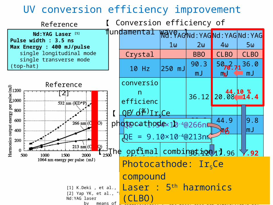
UV conversion efficiency improvement
Nd:YAG1ω
Nd:YAG 2ω
Nd:YAG 4ω
Nd:YAG 5ω
Crystal BBO CLBO CLBO10 Hz 250 mJ 90.3 mJ 50.2 mJ 36.0 mJ
conversion efficiency (%) 36.12 20.08 14.4
100 Hz 250 mJ 90.3 mJ 44.9 mJ 19.8 mJconversion
efficiency (%) 36.12 17.96 7.92
Reference [1]Nd:YAG Laser [1]
Pulse width : 3.5 nsMax Energy : 400 mJ/pulse single longitudinal mode single transverse mode (top-hat)
70.71 %
44.10 %
[1] K.Deki , et al., “CsLiB6O10 (CLBO) を用いた 193nm 光源の開発” , 光技術情報誌「ライトエッジ」 No.18[2] Yap YK, et al., "High-power fourth- and fifth-harmonic generation of a Nd:YAG laser by means of a CsLiB(6)O(10).", Opt Lett. 1996 Sep 1;21(17):1348-50.
Reference [2]
QE = 9.10×10⁻⁴@213nm
QE = 1.54×10⁻⁴@266nm×6
【 QE of Ir5Ce photocathode 】
Photocathode: Ir5Ce compoundLaser : 5th harmonics (CLBO)
【 Conversion efficiency of fundamental wave 】
【 The optimal combination 】

Temperature dependence of Yb:YAG• Improvement of thermal and emission property
(Thermal lens effect) (Excitation density)
300K30kW/cm2
Pertier
GM+He
300K P/P0 = exp(g0z) ~ 2150K → g = 7 [cm-1]
10 W/m/K , dn/dT = 8ppm/K @ 300K25 W/m/K , dn/dT = 3ppm/K @ 150K ↑150K 1/6 Thermal lens
Same gain @ 1/3 excitation density → ↓
150K => 1/20 thermal lens
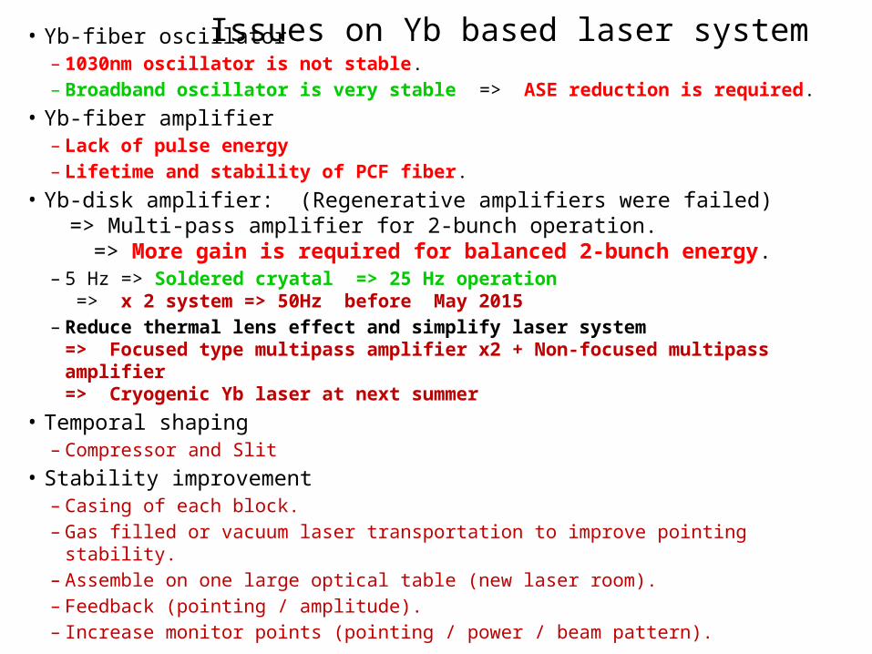
Issues on Yb based laser system• Yb-fiber oscillator– 1030nm oscillator is not stable.– Broadband oscillator is very stable => ASE reduction is required.
• Yb-fiber amplifier– Lack of pulse energy– Lifetime and stability of PCF fiber.
• Yb-disk amplifier: (Regenerative amplifiers were failed) => Multi-pass amplifier for 2-bunch operation.
=> More gain is required for balanced 2-bunch energy.– 5 Hz => Soldered cryatal => 25 Hz operation
=> x 2 system => 50Hz before May 2015– Reduce thermal lens effect and simplify laser system
=> Focused type multipass amplifier x2 + Non-focused multipass amplifier=> Cryogenic Yb laser at next summer
• Temporal shaping– Compressor and Slit
• Stability improvement– Casing of each block.– Gas filled or vacuum laser transportation to improve pointing stability.– Assemble on one large optical table (new laser room).– Feedback (pointing / amplitude).– Increase monitor points (pointing / power / beam pattern).