Embed Size (px)
Citation preview

Mumbai University EXTC (Semester -III)
1 |www.brainheaters.in
Solution for Electronic
Instruments and Measurements
May 2016
Index
Q.1)
a) …………………………………………………………………………. 2
b) …………………………………………………………………………. 3
c) …………………………………………………………………………. 4 -5
d) …………………………………………………………………………. 6
e) …………………………………………………………………………. 6
f) …………………………………………………………………………. 7
Q.2)
a) …………………………………………………………………………. 7-10
b) …………………………………………………………………………. 10-11
Q.3)
a) …………………………………………………………………………. 11-15
b) ………………………………………………………………………….16-18
Q.4)
a) ………………………………………………………………………….18-20
b) …………………………………………………………………………. 20-22
Q.5)
a) …………………………………………………………………………. N.A
b) …………………………………………………………………………. 23-24
Q.6)
a) …………………………………………………………………………. 24-25
b) …………………………………………………………………………. N.A
c) …………………………………………………………………………. 26-28
d) …………………………………………………………………………. 28-29
Mumbai University EXTC (Semester -III)
2 |www.brainheaters.in
Q1) Answer any four.
a) Explain alternate mode and chop mode in a dual trace
oscilloscope.
Ans: Alternate Mode : A display mode of operation in which the oscilloscope
completes tracing one channel before beginning to trace another channel.
Chop Mode : A display mode of operation in which small time segments
of each channel are traced sequentially so that more than one waveform
can appear on the screen simultaneously.
Alternate and Chop Display
On analogue scopes, multiple channels are displayed using either an alternate or
chop mode. (Digital oscilloscopes do not normally use chop or alternate mode.)
Alternate mode draws each channel alternately - the oscilloscope completes one
sweep on channel 1, then one sweep on channel 2, a second sweep on channel 1,
and so on. Use this mode with medium- to high-speed signals, when the sec/div
scale is set to 0.5 ms or faster.
Chop mode causes the oscilloscope to draw small parts of each signal by
switching back and forth between them. The switching rate is too fast for you to
notice, so the waveform looks whole. You typically use this mode with slow
signals requiring sweep speeds of 1 ms per division or less.

Mumbai University EXTC (Semester -III)
3 |www.brainheaters.in
b) What is cold junction compensation in thermocouples.
Ans:
Metal used for thermocouple
Copper-constantan alloy: 0-
200000 F
Iron-conatanatn alloy : 0-12000F
Platinum –Platinum/Rhodium
alloy: 0-30000 F
Chromel – Alumel alloy :0-9000 F
Mumbai University EXTC (Semester -III)
4 |www.brainheaters.in
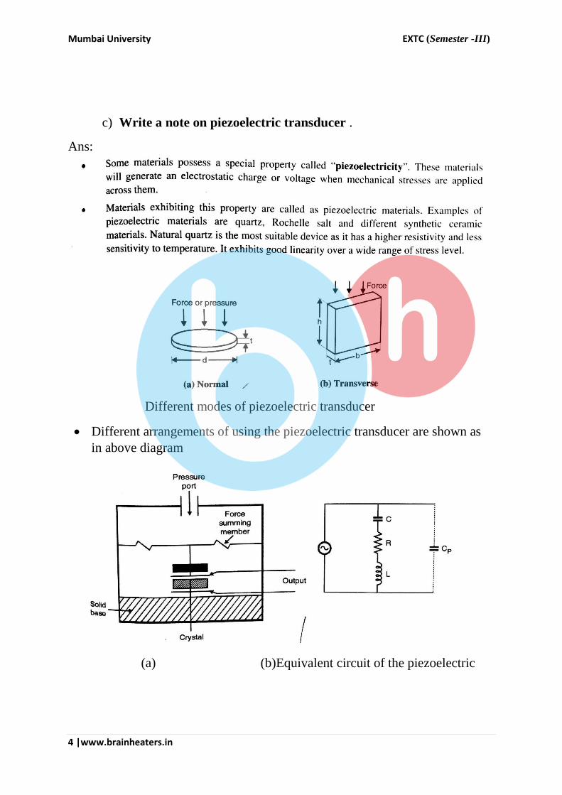
c) Write a note on piezoelectric transducer .
Ans:
Different modes of piezoelectric transducer
Different arrangements of using the piezoelectric transducer are shown as
in above diagram
(a) (b)Equivalent circuit of the piezoelectric

Mumbai University EXTC (Semester -III)
5 |www.brainheaters.in
Mumbai University EXTC (Semester -III)
6 |www.brainheaters.in
d) Which is fastest ADC and why?
Ans: Flash converters are extremely fast compared to many other types of
ADCs, which usually narrow in on the "correct" answer over a series of stages.
Compared to these, a flash converter is also quite simple and, apart from the
analogue comparators, only requires logic for the final conversion to binary.
For best accuracy, often a track-and-hold circuit is inserted in front of the ADC
input. This is needed for many ADC types (like successive approximation
ADC), but for flash ADCs there is no real need for this, because the
comparators are the sampling devices.
A flash converter requires a huge number of comparators compared to other
ADCs, especially as the precision increases. A flash converter
requires comparators for an n-bit conversion. The size, power consumption
and cost of all those comparators makes flash converters generally impractical
for precisions much greater than 8 bits (255 comparators). In place of these
comparators, most other ADCs substitute more complex logic and/or analogue
circuitry that can be scaled more easily for increased precision.
e) Define accuracy ,precision and sensitivity with suitable example.
Ans : a) Sensitivity: The sensitivity is defined as mV/mm . and it is typically 1
to 2 mV/0.01 mm for the LVDT Sensitivity should be as high as possible and
the typical value of LVDT sensitivity shows that it is a highly sensitive
transducer
b) Accuracy: It indicates the deviation of actual output from the theoretical
value. It depends on the accuracy of the resistors used in ladder and the
precision of the reference voltage used. It is also specified in terms of
percentage of full scale output e.g. If full scale output is 15V and accuracy is +
or – 0.1 % then the
maximum error =o.1x15/ 100 = 15mV
c) Precision: It is a measure of the responsibility of the measurement ,that is
given a fixed value of variable. Precision is a measure of the degree of which
successive measurements differ from each other.
Mumbai University EXTC (Semester -III)
7 |www.brainheaters.in
f) Compare Analogue instrument with digital instrument.
Ans: An analogue instrument gives an output which varies continuously as the
quantity being measured changes. The output can have an infinite number of
values within the range that the instrument is designed to measure. The
deflection type of pressure gauge a good example of an analogue instrument. As
the input value changes, the pointer moves with a smooth continuous motion.
Whilst the pointer can therefore be in an infinite number of positions within its
range of movement, the number of different positions which the eye can
discriminate between is strictly limited, this discrimination being dependent
upon how large the scale is and how finely it is divided.
A digital instrument has an output which varies in discrete steps and so can only
have a finite number of values. A cam is attached to the revolving body whose
motion is being measured, and on each revolution the cam opens and closes a
switch. The switching operations are counted by an electronic counter. This
system can only count whole revolutions and cannot discriminate any motion
which is less than a full revolution.
Q2)
a) Explain the principle, working and construction of LVDT. What
is meant by residual voltage.:
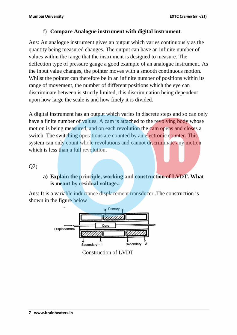
Ans: It is a variable inductance displacement transducer .The construction is
shown in the figure below
Construction of LVDT

Mumbai University EXTC (Semester -III)
8 |www.brainheaters.in
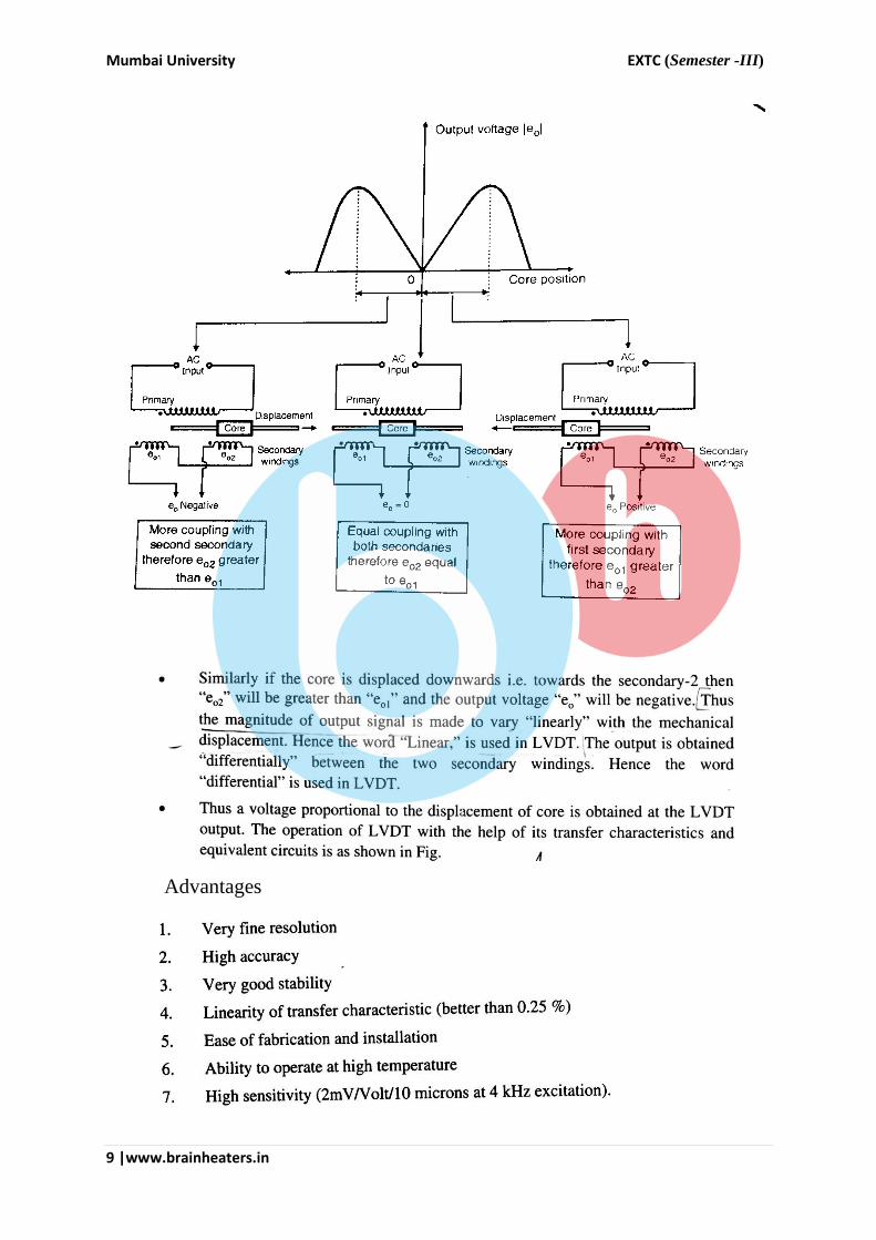
(a) Construction of LVDT winding (b)transfer characteristic of LVDT
Operation of LVDT :
Mumbai University EXTC (Semester -III)
9 |www.brainheaters.in
Advantages

Mumbai University EXTC (Semester -III)
10 |www.brainheaters.in
Disadvanatges:
b) Draw neat block diagram of Dual beam oscilloscope. Give the
comparison between Dual trace and trace beam oscilloscope.
Ans: Dual Beam Oscillator.
The block diagram of dual beam CRO is shown in the figure below.
It consist of two separate electron beam .Each electron beam has its own
vertical deflection plates and a common set of horizontal deflection plates
.This means time base is common for both the channels.

Mumbai University EXTC (Semester -III)
11 |www.brainheaters.in
comparison between Dual trace and trace beam oscilloscope.
Q3)
a) What are the various D/A converting techniques? Explain any
one technique.
Ans:
Classification of data converters
Mumbai University EXTC (Semester -III)
12 |www.brainheaters.in
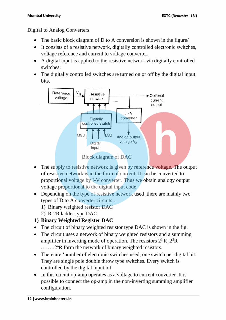
Digital to Analog Converters.
The basic block diagram of D to A conversion is shown in the figure/
It consists of a resistive network, digitally controlled electronic switches,
voltage reference and current to voltage converter.
A digital input is applied to the resistive network via digitally controlled
switches.
The digitally controlled switches are turned on or off by the digital input
bits.
Block diagram of DAC
The supply to resistive network is given by reference voltage. The output
of resistive network is in the form of current .It can be converted to
proportional voltage by I-V converter. Thus we obtain analogy output
voltage proportional to the digital input code.
Depending on the type of resistive network used ,there are mainly two
types of D to A converter circuits .
1) Binary weighted resistor DAC
2) R-2R ladder type DAC
1) Binary Weighted Register DAC
The circuit of binary weighted resistor type DAC is shown in the fig.
The circuit uses a network of binary weighted resistors and a summing
amplifier in inverting mode of operation. The resistors 21 R ,22R
,…….2nR form the network of binary weighted resistors.
There are ‘number of electronic switches used, one switch per digital bit.
They are single pole double throw type switches. Every switch is
controlled by the digital input bit.
In this circuit op-amp operates as a voltage to current converter .It is
possible to connect the op-amp in the non-inverting summing amplifier
configuration.

Mumbai University EXTC (Semester -III)
13 |www.brainheaters.in
The polarity of reference voltage depend on the type of switches used.
For example if we use the TTL switches then the reference voltage VR
=+5V and the output voltage of DAC will be negative. For example, if digital input bit d1 =1,then switch will connect resistor
21R to a negative reference voltage (-VR) and when digital input bit d1
=0,then switch will connect resistor 21 R to ground.
Thus an n-bit digital input will decide the position of all the switches and
connect their corresponding resistor to either –VR or ground.
The current will flow through binary resistor if switch connect resistor to
reference voltage .the current will not flow through binary weighted
resistor if switch connects resistor to ground.
Circuit diagram of binary weighted resistor DAC
Applying KCL at node 2 ,we get
I1+ I2+…………+In = Iin + If
Current going into op-amp terminal Iin is zero as op-amp has very high
input resistance.
I1 = -VR – V2 / 21 R , I2 = -VR – V2 / 2
2 R ,
In = -VR – V2 / 2n R ,
If = -VR – V0 / Rf
Mumbai University EXTC (Semester -III)
14 |www.brainheaters.in
From virtual ground concept ,as node 1is at ground potential so node 2 is
also at ground potential ,therefore V2= 0.
Therefore ,
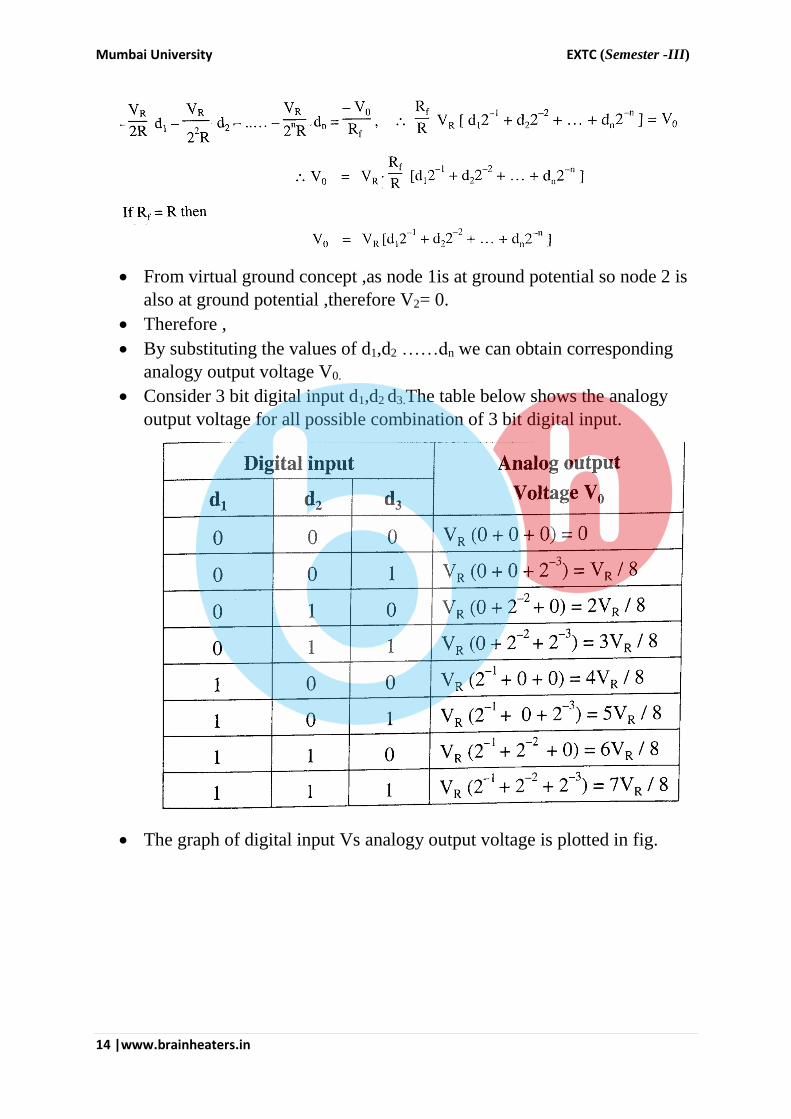
By substituting the values of d1,d2 ……dn we can obtain corresponding
analogy output voltage V0.
Consider 3 bit digital input d1,d2 d3.The table below shows the analogy
output voltage for all possible combination of 3 bit digital input.
The graph of digital input Vs analogy output voltage is plotted in fig.

Mumbai University EXTC (Semester -III)
15 |www.brainheaters.in
Advantages:
1) Circuit is simple
2) Easy calculation
Disadvantages:
1) The accuracy and stability of this type of DAC depends on the accuracy
of the resistor used.
2) This type of DAC requires wide range of resistor values. If number of
digit per binary word is 12 then the smallest resistor is 2R and largest is
212R =4096 thus the largest resistor is 2048 times the smallest one.
3) The finite resistance of the switches will disturb the currents particularly
in MSB position when the current setting are small in value.
Mumbai University EXTC (Semester -III)
16 |www.brainheaters.in
b) What is the basic principle of wave analyser? Explain
heterodyne type wave analyser with application.
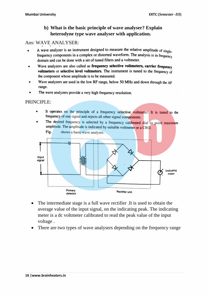
Ans: WAVE ANALYSER:
PRINCIPLE:
The intermediate stage is a full wave rectifier .It is used to obtain the
average value of the input signal, on the indicating peak. The indicating
meter is a dc voltmeter calibrated to read the peak value of the input
voltage .
There are two types of wave analysers depending on the frequency range

Mumbai University EXTC (Semester -III)
17 |www.brainheaters.in
HETRODYNE WAVE ANALYZER:

Mumbai University EXTC (Semester -III)
18 |www.brainheaters.in
Application:
Q4)
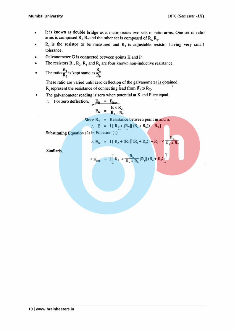
a) Explain Kelvin’s double bridge and its application in very low
resistance measurement?
Ans: * This method is one of the best available method for the precise
measurement of low resistance .
It is a development of the Wheatstone bridge by which the errors due to
contact and lead resistance are eliminated.
The schematic diagram of kelvin’s double is shown in the fig.
The known resistance R3 is adjusted such that galvanometer indicates
zero
Kelvin’s double bridge
Mumbai University EXTC (Semester -III)
19 |www.brainheaters.in

Mumbai University EXTC (Semester -III)
20 |www.brainheaters.in
Advantages :
1) In atypical Kelvin’s double bridge the range of resistance covered is 1Ω
to 10 µΩ with an accuracy of + or – 0.05 % to + or – 0.2%
2) The resistance of the connecting lead Ry has no effect on measurement .
b) Draw and explain Hay bridge and its application for measurement
of inductance.
Ans: Hay’s bridge:
This method of measurement is particularly suited for the measurement of
inductance having high Q value.
The schematic of Hay’s Bridge is shown below:

Mumbai University EXTC (Semester -III)
21 |www.brainheaters.in
Hay’s Bridge differs from Maxwell’s bridge by having a resistance R1 in
series with a capacitor C1 instead of being parallel.
For large phase angles,R1 needs to be low, therefore this bridge is more
convenient for measuring high Q coils .For Q=10 ,the error is+ or – and
for Q = 30 ,The error is + or – 0.1%

Mumbai University EXTC (Semester -III)
22 |www.brainheaters.in

Mumbai University EXTC (Semester -III)
23 |www.brainheaters.in
Q5)
a) Explain the principle and working of operation of dual slope
DVM.
Ans: N.A
b) Define Q factor and explain working of a Q meter for Q factor
measurement.
Ans:
Mumbai University EXTC (Semester -III)
24 |www.brainheaters.in
Q6)
a) Draw block diagram for generalized measurement system and
explain its components.
Ans:
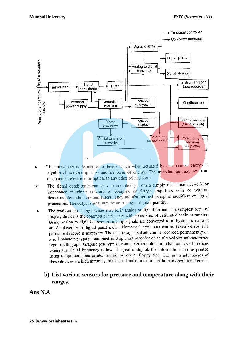
Mumbai University EXTC (Semester -III)
25 |www.brainheaters.in
b) List various sensors for pressure and temperature along with their
ranges.
Ans N.A
Mumbai University EXTC (Semester -III)
26 |www.brainheaters.in
c) Brief out classification of error in measurement.
Ans: 1)Gross Error:
2) Systematic error:

Mumbai University EXTC (Semester -III)
27 |www.brainheaters.in
(a) Instrumental errors:
(b) Environmental errors:
3) Schematic error

Mumbai University EXTC (Semester -III)
28 |www.brainheaters.in
4) Format error:
d) Explain Electrodynamometer type wall meter.
Ans:
CONSTRUCTION

Mumbai University EXTC (Semester -III)
29 |www.brainheaters.in
1) The Fixed Coil.
The fixed coils carry current of the circuit,
They are divided into two halves.
The fixed coils are easily chosen to be current coils because they can be
made more massive and can be easily constructed to carry considerable
current.
They are air cored and wound with heavy wire. This wire is stranded or
laminated especially when carrying losses in conductor.
The fixed coils of earlier watt meters were designed to carry a current of
100 A but modern design usually limit the maximum current to 20 A.
In the case of precision watt meters, the two halves of the fixed coil,
which are connected in series for a basic measuring range, can be
connected in parallel to increase the wattmeter current range to twice its
original value. Shunt are not used for extension of current range since
they are subject to temperature errors.
2) Moving coil:
The moving coil is mounted on a pivoted spindle and is entirely embraced
by the fixed current coils. It is air cored.
The spring control is used for the movement of coil.
Since the current of the moving coil is carried by the instrument springs,
it is limited to the values which can be carried safely by springs without
appreciable heating .A series resistor is used to limit the current.
The voltage rating of the wattmeter is limited to about 600 V by the
power requirements of the voltage circuit since most of the power is
absorbed by the resistance in series with the moving coil.
3) Damping element:
The light aluminium vane carried by moving system acts as damping
element .It moves in a sector shaped box and provides air friction
damping. Electromagnetic or eddy current damping is not used as
introduction of permanent magnet will gently distort the weak operating
magnetic field.
4) Control element:
Spring control is used for this instruction.
5) Scales and pointers:
They are equipped with minor type scales and knife edge pointers to
remove reading errors due to parallax.

Mumbai University EXTC (Semester -III)
30 |www.brainheaters.in