Embed Size (px)
Citation preview
SSSOOOLLLUUUZZZIIIOOONNNIII PPPEEERRR LLLAAA CCCAAALLLDDDAAARRREEERRRIIIAAA EEE CCCAAARRRPPPEEENNNTTTEEERRRIIIAAA
PPPRRREEESSSSSSUUURRREEE VVVEEESSSSSSEEELLLSSS AAANNNDDD CCCAAARRRPPPEEENNNTTTRRRYYY SSSOOOLLLUUUTTTIIIOOONNNSSS
MAPECC s.r.l. Uffici Tecnici e Commerciali Strada di Pantano, 20/E - 05100 Terni - Italy
2
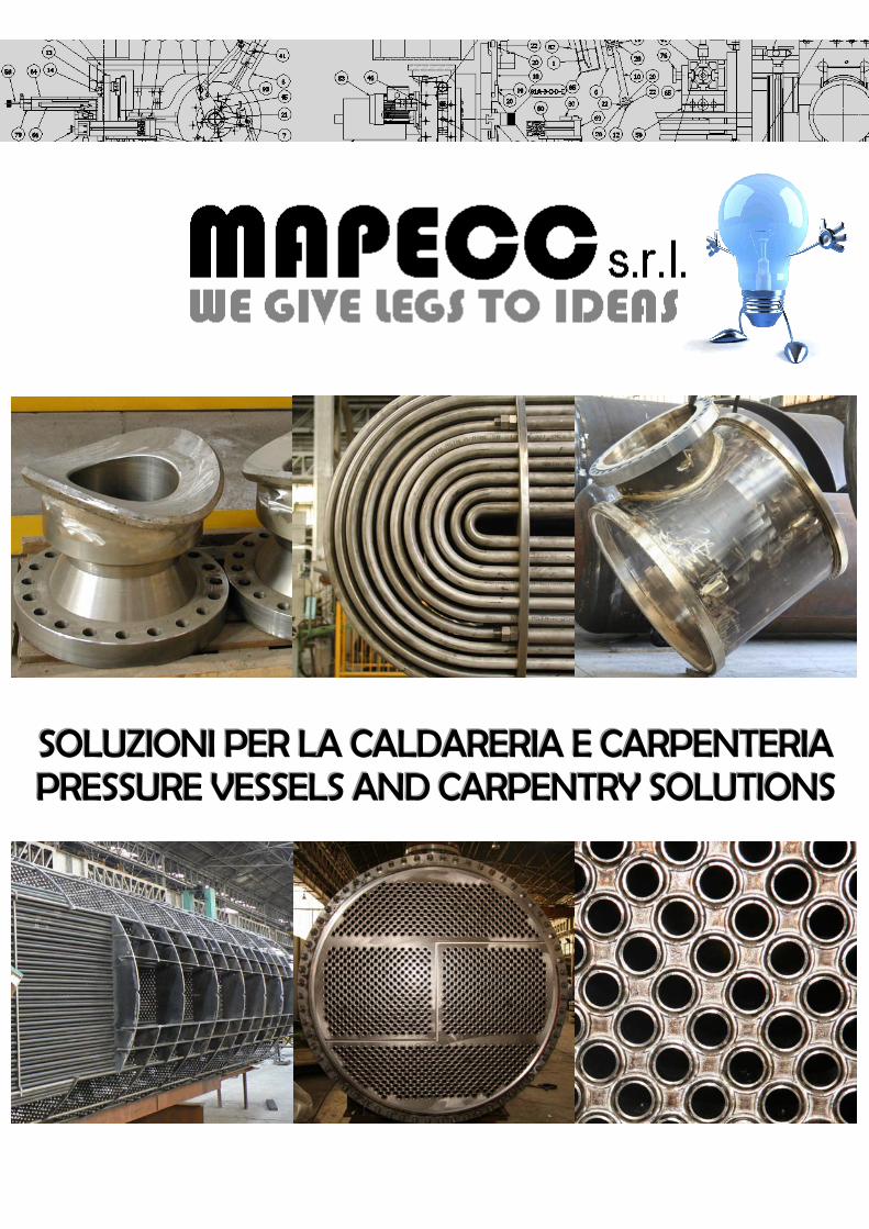
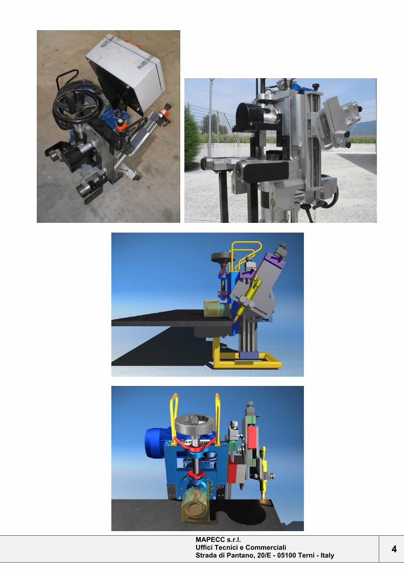
BISELLATRICE / CHAMFERING MACHINE [BO-1A]
DESCRIZIONE
Semplice macchina per preparare alla saldatura i bordi di lamiere e qualsiasi profilo abbia disponibile un lembo piatto di larghezza minima di 150mm che rappresenta la pista di scorrimento delle rotelle di appoggio e trazione; compatta e maneggevole, facilmente trasportabile, non richiede ribaltamento lamiere. Può operare sia con cannello ossiacetilenico che con plasma. Alla macchina può essere abbinato il modulo di fresatura/splaccatura BS-1A (opzionale), che permette la realizzazione di cianfrini e splaccatura di lamiere placcate per asportazione di truciolo.
DESCRIPTION
Simple machine to bevel edges for welding. It can be used on plates and every section with a free flat edge, 150mm min wide, that represents the sliding track of the bearing and traction wheels. It’s compact, easy to handle and to move; no plate overturning is required. It can work with both oxyacetylene and plasma torch. It can be equipped with the milling/cladding removal machine BS-1A (optional), that allows the execution of chamfers and the removal of cladding on clad plates through chip-forming machining.
MAPECC s.r.l. Uffici Tecnici e Commerciali Strada di Pantano, 20/E - 05100 Terni - Italy
3
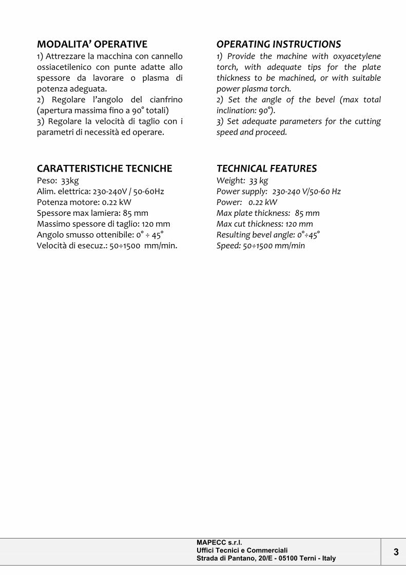
MODALITA’ OPERATIVE
1) Attrezzare la macchina con cannello ossiacetilenico con punte adatte allo spessore da lavorare o plasma di potenza adeguata. 2) Regolare l’angolo del cianfrino (apertura massima fino a 90° totali) 3) Regolare la velocità di taglio con i parametri di necessità ed operare.
OPERATING INSTRUCTIONS
1) Provide the machine with oxyacetylene torch, with adequate tips for the plate thickness to be machined, or with suitable power plasma torch. 2) Set the angle of the bevel (max total inclination: 90°). 3) Set adequate parameters for the cutting speed and proceed.
CARATTERISTICHE TECNICHE
Peso: 33kg Alim. elettrica: 230-240V / 50-60Hz Potenza motore: 0.22 kW Spessore max lamiera: 85 mm Massimo spessore di taglio: 120 mm Angolo smusso ottenibile: 0° ÷ 45° Velocità di esecuz.: 50÷1500 mm/min.
TECHNICAL FEATURES
Weight: 33 kg Power supply: 230-240 V/50-60 Hz Power: 0.22 kW Max plate thickness: 85 mm Max cut thickness: 120 mm Resulting bevel angle: 0°÷45° Speed: 50÷1500 mm/min
MAPECC s.r.l. Uffici Tecnici e Commerciali Strada di Pantano, 20/E - 05100 Terni - Italy
4
MAPECC s.r.l. Uffici Tecnici e Commerciali Strada di Pantano, 20/E - 05100 Terni - Italy
5
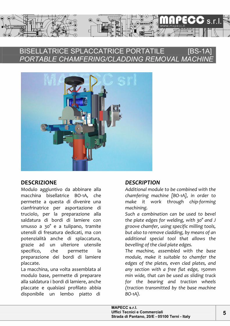
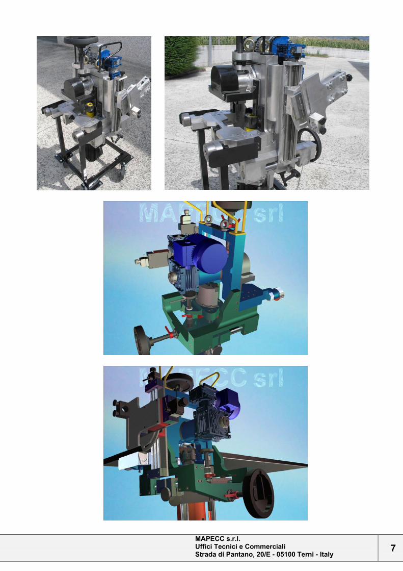
BISELLATRICE SPLACCATRICE PORTATILE [BS-1A] PORTABLE CHAMFERING/CLADDING REMOVAL MACHINE
DESCRIZIONE
Modulo aggiuntivo da abbinare alla macchina bisellatrice BO-1A, che permette a questa di divenire una cianfrinatrice per asportazione di truciolo, per la preparazione alla saldatura di bordi di lamiere con smusso a 30° e a tulipano, tramite utensili di fresatura dedicati, ma con potenzialità anche di splaccatura, grazie ad un ulteriore utensile specifico, che permette la preparazione dei bordi di lamiere placcate. La macchina, una volta assemblata al modulo base, permette di preparare alla saldatura i bordi di lamiere, anche placcate e qualsiasi profilato abbia disponibile un lembo piatto di
DESCRIPTION
Additional module to be combined with the chamfering machine [BO-1A], in order to make it work through chip-forming machining. Such a combination can be used to bevel the plate edges for welding, with 30° and J groove chamfer, using specific milling tools, but also to remove cladding, by means of an additional special tool that allows the bevelling of the clad plate edges. The machine, assembled with the base module, make it suitable to chamfer the edges of the plates, even clad plates, and any section with a free flat edge, 150mm min wide, that can be used as sliding track for the bearing and traction wheels (traction transmitted by the base machine BO-1A).
MAPECC s.r.l. Uffici Tecnici e Commerciali Strada di Pantano, 20/E - 05100 Terni - Italy
6
larghezza minima di 150mm che rappresenta la pista di scorrimento delle rotelle di appoggio e trazione (trazione data dalla macchina base BO-1A); compatta e maneggevole, facilmente trasportabile, non richiede ribaltamento lamiere.
It’s compact, easy to handle and to move; no plate overturning is required..
MODALITA’ OPERATIVE
1) Attrezzare la macchina montando sull’albero porta-fresa, l’utensile necessario. 2) Regolare, tramite i volantini, altezza e “profondità” di penetrazione dell’utensile sul lembo. 3) Regolare la velocità di taglio con i parametri di necessità ed operare.
OPERATING INSTRUCTIONS
1) Provide the machine with the required tool, that has to be installed on the cutter holder arbor. 2) Set the tool penetration height and depth on the edge, through the little hand wheels. 3) Set adequate parameters for the cutting speed and proceed.
CARATTERISTICHE TECNICHE
Peso unità: 73 kg (tot. 115 kg assemblato con unità BO-1A + telaio con ruote) Alim. elettrica: 230-240V / 50-60Hz Potenza motore: 4 kW Spessore max lamiera: 85 Bordo ottenibile: smusso a V o X con semi-angolo 30° ; mezzo tulipano a 9°; splaccatura Velocità di esecuzione: 200 ÷ 500 mm al minuto.
TECHNICAL FEATURES
Unit weight: 73kg (tot 115 kg if assembled with machine BO-1A + frame with wheels). Power supply: 230-240 –v / 50-60 Hz Motor power: 4 kW Max plate thickness: 85 mm Resulting edge: V or X bevel with half angle 30°; J bevel at 9°; -cladding removal. Speed: 200÷500 mm/min
MAPECC s.r.l. Uffici Tecnici e Commerciali Strada di Pantano, 20/E - 05100 Terni - Italy
7
MAPECC s.r.l. Uffici Tecnici e Commerciali Strada di Pantano, 20/E - 05100 Terni - Italy
8
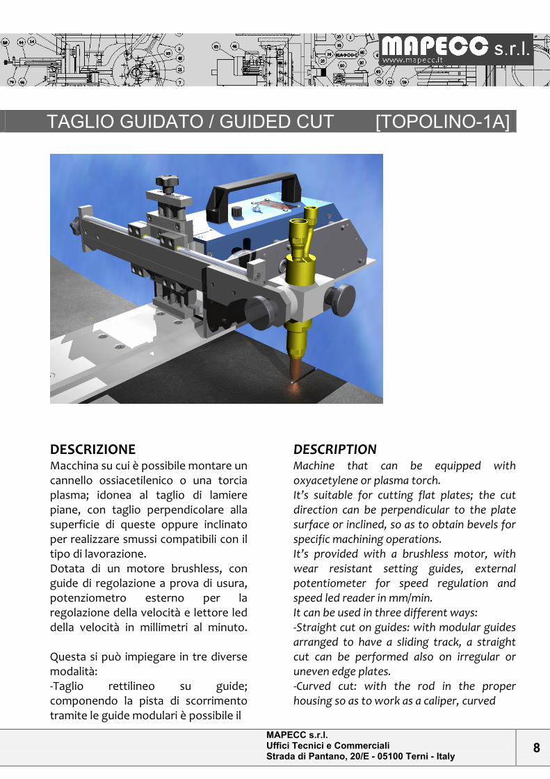
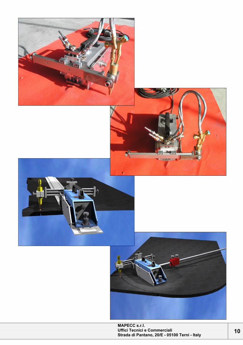
TAGLIO GUIDATO / GUIDED CUT [TOPOLINO-1A]
DESCRIZIONE
Macchina su cui è possibile montare un cannello ossiacetilenico o una torcia plasma; idonea al taglio di lamiere piane, con taglio perpendicolare alla superficie di queste oppure inclinato per realizzare smussi compatibili con il tipo di lavorazione. Dotata di un motore brushless, con guide di regolazione a prova di usura, potenziometro esterno per la regolazione della velocità e lettore led della velocità in millimetri al minuto. Questa si può impiegare in tre diverse modalità: -Taglio rettilineo su guide; componendo la pista di scorrimento tramite le guide modulari è possibile il
DESCRIPTION
Machine that can be equipped with oxyacetylene or plasma torch. It’s suitable for cutting flat plates; the cut direction can be perpendicular to the plate surface or inclined, so as to obtain bevels for specific machining operations. It’s provided with a brushless motor, with wear resistant setting guides, external potentiometer for speed regulation and speed led reader in mm/min. It can be used in three different ways: -Straight cut on guides: with modular guides arranged to have a sliding track, a straight cut can be performed also on irregular or uneven edge plates. -Curved cut: with the rod in the proper housing so as to work as a caliper, curved
MAPECC s.r.l. Uffici Tecnici e Commerciali Strada di Pantano, 20/E - 05100 Terni - Italy
9
taglio rettilineo anche di lamiere con bordi imperfetti o frastagliati. -Taglio curvo; montando nell’apposito alloggiamento l’asta che adempie alla funzione di compasso si possono eseguire tagli curvi . -Taglio libero: guidata a mano da un operatore può seguire tracciature di taglio particolari, conservando costantemente l’inclinazione impostata per tutto lo sviluppo del taglio.
-Curved cut: with the rod in the proper housing so as to work as a caliper, curved cuts can be performed. -Free cut: hand-guided by an operator, special cuts can be performed, maintaining the same constant inclination along the whole cut.
MODALITA’ OPERATIVE
1) Attrezzare la macchina con cannello ossiacetilenico con punte adatte allo spessore da lavorare o plasma di potenza adeguata. 2) Regolare posizione di taglio (tramite slitta trasversale) e angolo del cianfrino (apertura massima fino a 45°) 3) Regolare la velocità di taglio con i parametri idonei ed operare
OPERATING INSTRUCTIONS
1) Provide the machine with oxyacetylene torch, with adequate tips for the plate thickness to be machined, or with suitable power plasma torch. 2) Set the cut position (through the transversal slide) and the angle of the bevel (max inclination: 45°). 3) Set adequate parameters for the cutting speed and proceed.
CARATTERISTICHE TECNICHE
Peso: 13kg Alimentazione elettrica: 24 V AC Potenza resa motore: 40 W Massimo spessore di taglio: 300 mm (ossitaglio) Max spess. di taglio: * mm (plasma) [*: funzione della potenza del generatore] Angolo smusso ottenibile: 0° ÷ 45° Velocità di esecuzione: 0÷2500 mm al minuto.
TECHNICAL FEATURES
Weight: 13 kg Power supply: 24 V AC Power: 40 W Max cut thickness: 300 mm (oxygen cutting) Max cut thickness: * mm (plasma cutting) [* function of the generator power]
Resulting bevel angle: 0°÷45° Speed: 0÷2500 mm/min
MAPECC s.r.l. Uffici Tecnici e Commerciali Strada di Pantano, 20/E - 05100 Terni - Italy
10
MAPECC s.r.l. Uffici Tecnici e Commerciali Strada di Pantano, 20/E - 05100 Terni - Italy
11
POSIZIONATORE BOCCHELLI [PB-1A] / [PB-2A] NOZZLE POSITIONER
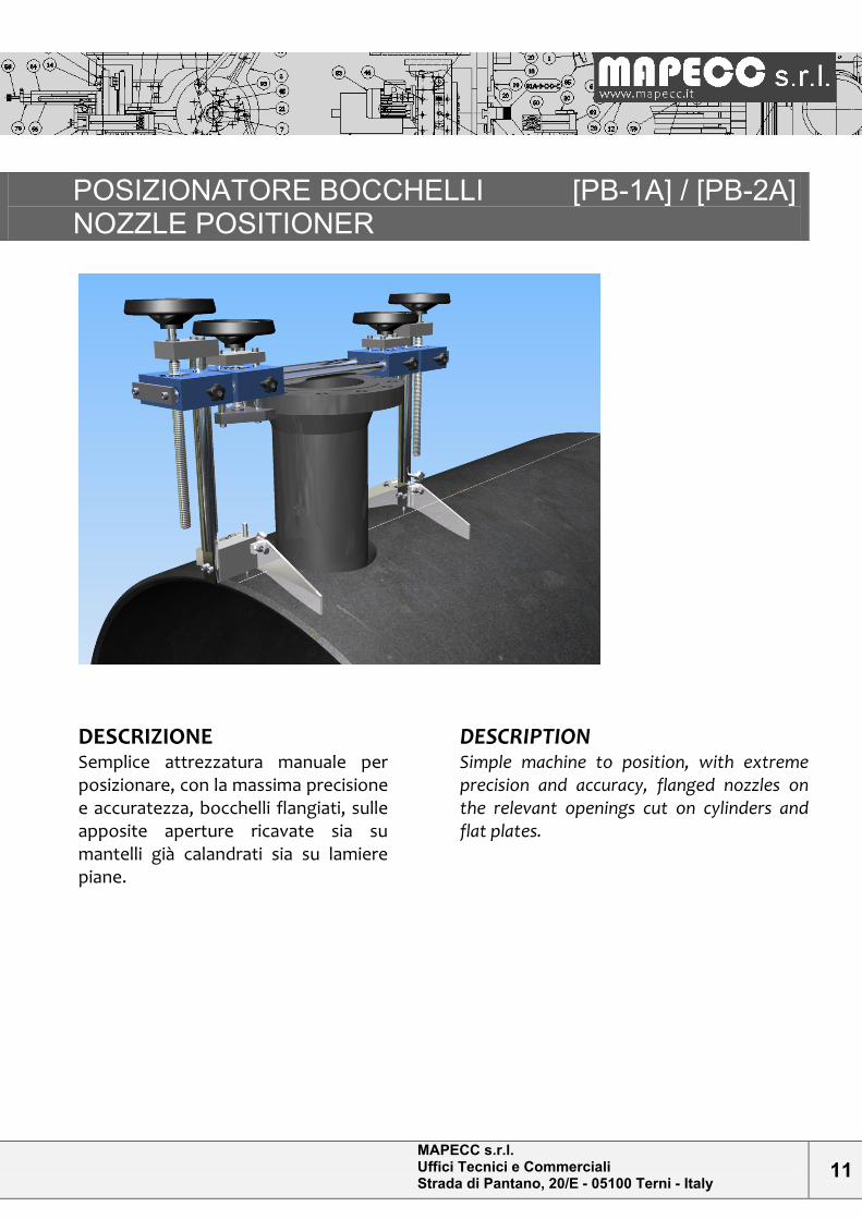
DESCRIZIONE Semplice attrezzatura manuale per posizionare, con la massima precisione e accuratezza, bocchelli flangiati, sulle apposite aperture ricavate sia su mantelli già calandrati sia su lamiere piane.
DESCRIPTION
Simple machine to position, with extreme precision and accuracy, flanged nozzles on the relevant openings cut on cylinders and flat plates.
MAPECC s.r.l. Uffici Tecnici e Commerciali Strada di Pantano, 20/E - 05100 Terni - Italy
12
MODALITA’ OPERATIVE 1) Tracciare un’asse (mezzeria fori) sulla parte piana flangia/bocchello facendo attenzione a non interferire con la battuta della flangia stessa. 2) Inserire lo spessore flangia nelle apposite ganasce superiori. 3) Far coincidere il bordo esterno flangia con le battute ganasce curando l’allineamento longitudinale con la tracciatura asse posizionatore/asse flangia e serrare. 4) Appoggiare l’attrezzatura completa di bocchello sul mantello o lamiera e allineare, a mezzo dei puntali esterni, con l’asse longitudinale. 5) Concludere quindi il posizionamento calando il bocchello nell’apertura, tramite i volantini esterni, fino a raggiungere la sporgenza richiesta. La sporgenza potrà essere controllata misurando l’altezza di necessità sui blocchetti di estremità attrezzatura. La versione PB-1A permette di operare con bocchelli aventi flangia con diametro esterno non superiore a 350mm; per flange di diametro superiore va adottato il posizionatore versione PB-2A.
OPERATING INSTRUCTIONS
1) Trace an axis (such that the holes straddle it) on the flat surface of flange/nozzle, without interfering with the flange sealing face. 2) Grasp the flange thickness with the upper jaw. 3) Make the flange external edge mate with the jaw ledge, paying attention to the longitudinal alignment along the tracing positioner axis/flange axis and tighten. 4) Place the positioner, assembled with the nozzle, on the cylinder or the plate, aligning it along the longitudinal axis, through the external push rods. 5) Complete the positioning inserting the nozzle into the hole, by means of external handwheels, to the right projection. The projection can be checked by measuring the necessary distance on the equipment extreme blocks. Positioner type PB-1A can be used for nozzles with external flange diameter not larger than 350mm, whereas positioner type PB-2A must be used for larger flange diameter.
CARATTER. TECNICHE [PB-1A] Peso: 32 kg Bocchello applicabile: diametro flangia: min 2” ÷ 8” (300#) Sporgenza flangia rispetto al mantello: min 80 ÷ max 300
TECHNICAL FEATURES[PB-1A] Weight: 32 kg Applicable nozzle: flange diameter min 2”/max 8” (300#) Flange projection from the external cylinder/plate surface: min 80mm/max 300mm
MAPECC s.r.l. Uffici Tecnici e Commerciali Strada di Pantano, 20/E - 05100 Terni - Italy
13
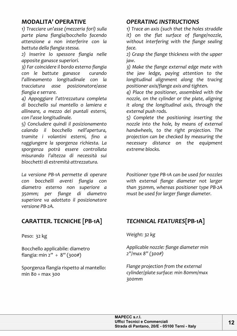
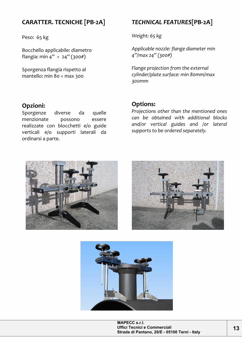
CARATTER. TECNICHE [PB-2A] Peso: 65 kg Bocchello applicabile: diametro flangia: min 4” ÷ 24” (300#) Sporgenza flangia rispetto al mantello: min 80 ÷ max 300
Opzioni: Sporgenze diverse da quelle menzionate possono essere realizzate con blocchetti e/o guide verticali e/o supporti laterali da ordinarsi a parte.
TECHNICAL FEATURES[PB-2A] Weight: 65 kg Applicable nozzle: flange diameter min 4”/max 24” (300#) Flange projection from the external cylinder/plate surface: min 80mm/max 300mm
Options: Projections other than the mentioned ones can be obtained with additional blocks and/or vertical guides and /or lateral supports to be ordered separately.
MAPECC s.r.l. Uffici Tecnici e Commerciali Strada di Pantano, 20/E - 05100 Terni - Italy
14
SALDATRICE ORBITALE [SO-1A] ORBITAL WELDING MACHINE
DESCRIZIONE
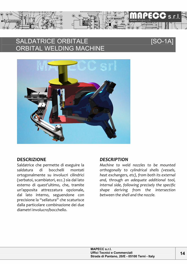
Saldatrice che permette di eseguire la saldatura di bocchelli montati ortogonalmente su involucri cilindrici (serbatoi, scambiatori, ecc.) sia dal lato esterno di quest’ultimo, che, tramite un’apposita attrezzatura opzionale, dal lato interno, seguendone con precisione la “sellatura” che scaturisce dalla particolare combinazione dei due diametri involucro/bocchello.
DESCRIPTION
Machine to weld nozzles to be mounted orthogonally to cylindrical shells (vessels, heat exchangers, etc), from both its external and, through an adequate additional tool, internal side, following precisely the specific shape deriving from the intersection between the shell and the nozzle.
MAPECC s.r.l. Uffici Tecnici e Commerciali Strada di Pantano, 20/E - 05100 Terni - Italy
15
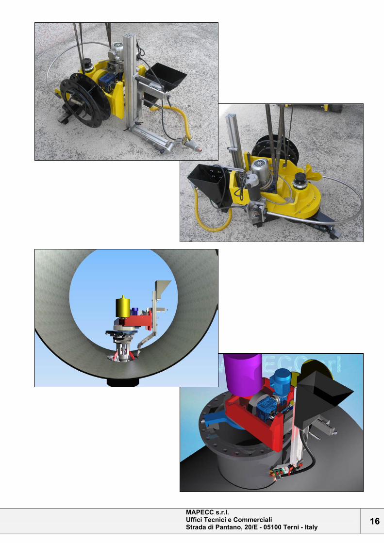
MODALITA’ OPERATIVE
Una volta che il bocchello è stato appuntato nella corretta posizione di montaggio sul mantello, si va a montare la macchina sul bocchello, con la torcia in asse con l’asse del mantello e nel suo punto di massima escursione superiore; Serrare l’autocentrante che si espanderà sull’interno di questo. Nel caso di saldatura interna, sarà l’apposita attrezzatura per interni che verrà montata internamente al bocchello, offrendo alla macchina di saldatura, un idoneo supporto su cui montarla. Far compiere alla macchina una rotazione di 90°, per portarla in asse al punto minimo di sellatura; registrare ora la vite del glifo oscillante, che farà scendere la torcia coincidente al punto più basso che dovrà raggiungere. Riportare la macchina nella posizione di partenza (punto massimo sellatura) e avviare la saldatura, con i giusti parametri operativi.
OPERATING INSTRUCTIONS
After fixing the nozzle in the correct position on the shell, the machine has to be mounted on the nozzle, with the torque axis coincident with the shell axis and in its maximum upper amplitude. Tighten the selfcentering that will extent to the internal side of the nozzle. In case of internal welding, the adequate tool for internals will be mounted inside the nozzle, so that the welding machine has got a suitable support to be mounted on. Make the machine rotate by 90°, in order to bring it in axis at the minimum point of curved region. Adjust the screw of the crank and slotted link, that will make the coincident torque go down to the lowest point to be reached. Bring the machine to the initial position (shape maximum height) and start the welding, with suitable operating parameters.
CARATTERISTICHE TECNICHE
Peso totale macchina (con accessori di saldatura): ~300kg Peso attrezzatura per saldatura interna: ~ 60kg Alimentazione elettrica: 400V 50÷60Hz Potenza motore: 0.37 kw Utilizzabile su bocchelli con dia. interno ~650mm Corsa regolabile glifo: max 140mm
TECHNICAL FEATURES
Total machine weight (with welding accessories): ~ 300kg Internal welding tool weight: ~ 60kg Power supply: 400 V/50÷60 Hz Power: 0.37 Kw Usable on internal diameter nozzles with internal diameter: ~650mm Adjustable traverse of the crank and slotted link: max 140mm
MAPECC s.r.l. Uffici Tecnici e Commerciali Strada di Pantano, 20/E - 05100 Terni - Italy
16
MAPECC s.r.l. Uffici Tecnici e Commerciali Strada di Pantano, 20/E - 05100 Terni - Italy
17
SVASATURA E REALIZZAZIONE CANALINI MACHINE FOR FLARING E GROOVING [MSC-1A]
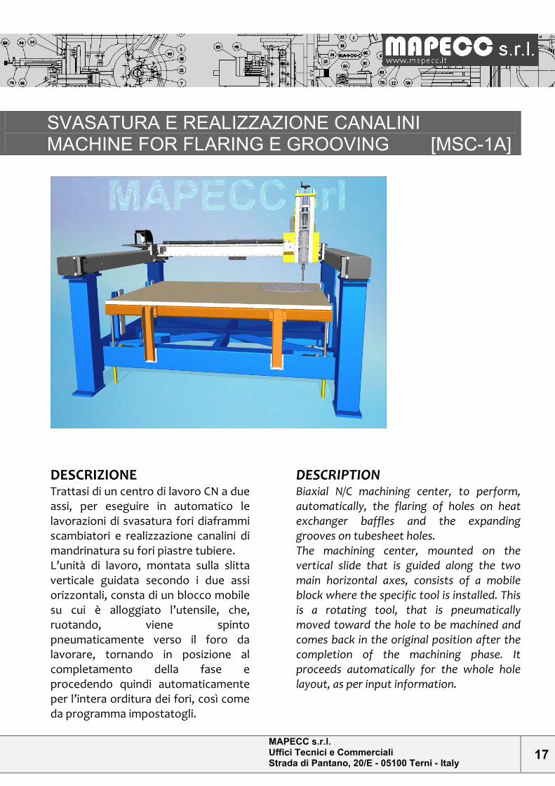
DESCRIZIONE
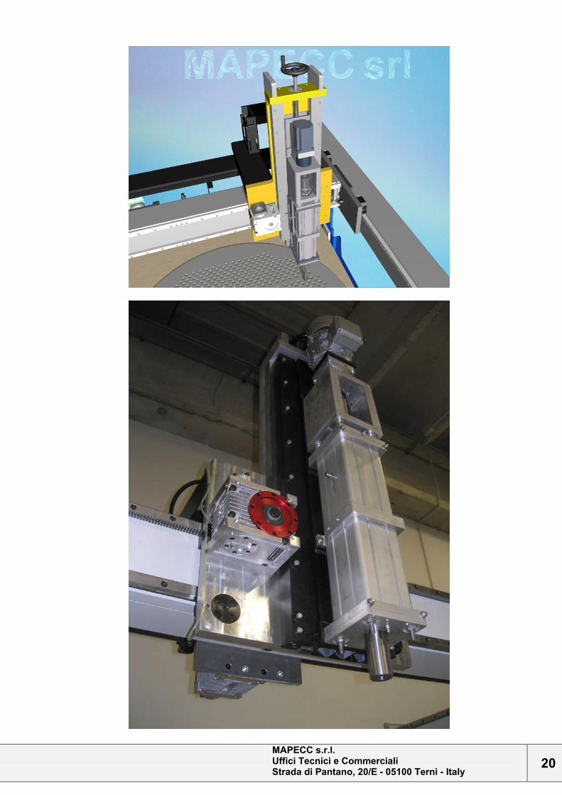
Trattasi di un centro di lavoro CN a due assi, per eseguire in automatico le lavorazioni di svasatura fori diaframmi scambiatori e realizzazione canalini di mandrinatura su fori piastre tubiere. L’unità di lavoro, montata sulla slitta verticale guidata secondo i due assi orizzontali, consta di un blocco mobile su cui è alloggiato l’utensile, che, ruotando, viene spinto pneumaticamente verso il foro da lavorare, tornando in posizione al completamento della fase e procedendo quindi automaticamente per l’intera orditura dei fori, così come da programma impostatogli.
DESCRIPTION
Biaxial N/C machining center, to perform, automatically, the flaring of holes on heat exchanger baffles and the expanding grooves on tubesheet holes. The machining center, mounted on the vertical slide that is guided along the two main horizontal axes, consists of a mobile block where the specific tool is installed. This is a rotating tool, that is pneumatically moved toward the hole to be machined and comes back in the original position after the completion of the machining phase. It proceeds automatically for the whole hole layout, as per input information.
MAPECC s.r.l. Uffici Tecnici e Commerciali Strada di Pantano, 20/E - 05100 Terni - Italy
18
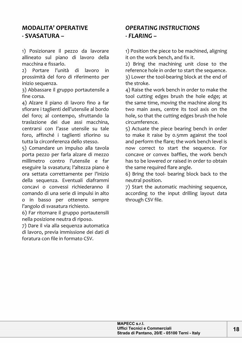
MODALITA’ OPERATIVE
- SVASATURA –
1) Posizionare il pezzo da lavorare allineato sul piano di lavoro della macchina e fissarlo. 2) Portare l’unità di lavoro in prossimità del foro di riferimento per inizio sequenza. 3) Abbassare il gruppo portautensile a fine corsa. 4) Alzare il piano di lavoro fino a far sfiorare i taglienti dell’utensile al bordo del foro; al contempo, sfruttando la traslazione dei due assi macchina, centrarsi con l’asse utensile su tale foro, affinché i taglienti sfiorino su tutta la circonferenza dello stesso. 5) Comandare un impulso alla tavola porta pezzo per farla alzare di mezzo millimetro contro l’utensile e far eseguire la svasatura; l’altezza piano è ora settata correttamente per l’inizio della sequenza. Eventuali diaframmi concavi o convessi richiederanno il comando di una serie di impulsi in alto o in basso per ottenere sempre l’angolo di svasatura richiesto. 6) Far ritornare il gruppo portautensili nella posizione neutra di riposo. 7) Dare il via alla sequenza automatica di lavoro, previa immissione dei dati di foratura con file in formato CSV.
OPERATING INSTRUCTIONS
- FLARING –
1) Position the piece to be machined, aligning it on the work bench, and fix it. 2) Bring the machining unit close to the reference hole in order to start the sequence. 3) Lower the tool-bearing block at the end of the stroke. 4) Raise the work bench in order to make the tool cutting edges brush the hole edge; at the same time, moving the machine along its two main axes, centre its tool axis on the hole, so that the cutting edges brush the hole circumference. 5) Actuate the piece bearing bench in order to make it raise by 0.5mm against the tool and perform the flare; the work bench level is now correct to start the sequence. For concave or convex baffles, the work bench has to be lowered or raised in order to obtain the same required flare angle. 6) Bring the tool- bearing block back to the neutral position. 7) Start the automatic machining sequence, according to the input drilling layout data through CSV file.
MAPECC s.r.l. Uffici Tecnici e Commerciali Strada di Pantano, 20/E - 05100 Terni - Italy
19
MODALITA’ OPERATIVE
- REALIZZAZIONE CANALINI –
1) Posizionare la piastra tubiera da lavorare allineata sul piano di lavoro della macchina e fissarla se occorre. 2) Portare l’unità di lavoro con l’utensile allineato sul foro di riferimento per l’inizio sequenza. 3) Abbassare il gruppo portautensile a fine corsa. 4) Alzare il piano di lavoro fino ad ottenere lo scarico molle dell’utensile per canalini 5) Far ritornare il gruppo portautensili nella posizione neutra di riposo. 6) Dare il via alla sequenza automatica di lavoro, previa immissione dei dati di foratura con file in formato CSV.
CARATTERISTICHE TECNICHE
Peso: ca 2700 kg. Alimentazione elettrica: 220/380 Volt 50/60 Hz Traslazione asse Y: 2000 mm Traslazione asse X: 2000 mm Max altezza pezzo caricabile: ca 450 mm Capacità produttiva: ca 2250 fori/ora (svasatura)
OPERATING INSTRUCTIONS
- GROOVING –
1) Position the tubesheet to be machined, aligning it on the work bench and fix it (if it’s necessary). 2) Bring the machining unit with aligned tool on the reference hole in order to start the sequence. 3) Lower the tool-bearing block at the end of the stroke. 4) Raise the work bench till the groove tool springs are released. 5) Bring the too- bearing block back to the neutral position. 6) Start the automatic machining sequence, according to the input drilling layout data through CSV file.
TECHNICAL FEATURES
Weight: ~2700 kg Power supply: 220/380 V 50/60 Hz Y axis translation: 2000mm X axis translation: 2000mm Machinable max piece height: ~450mm Production capability: ~2250 hole/hour (flaring)
MAPECC s.r.l. Uffici Tecnici e Commerciali Strada di Pantano, 20/E - 05100 Terni - Italy
20
MAPECC s.r.l. Uffici Tecnici e Commerciali Strada di Pantano, 20/E - 05100 Terni - Italy
21
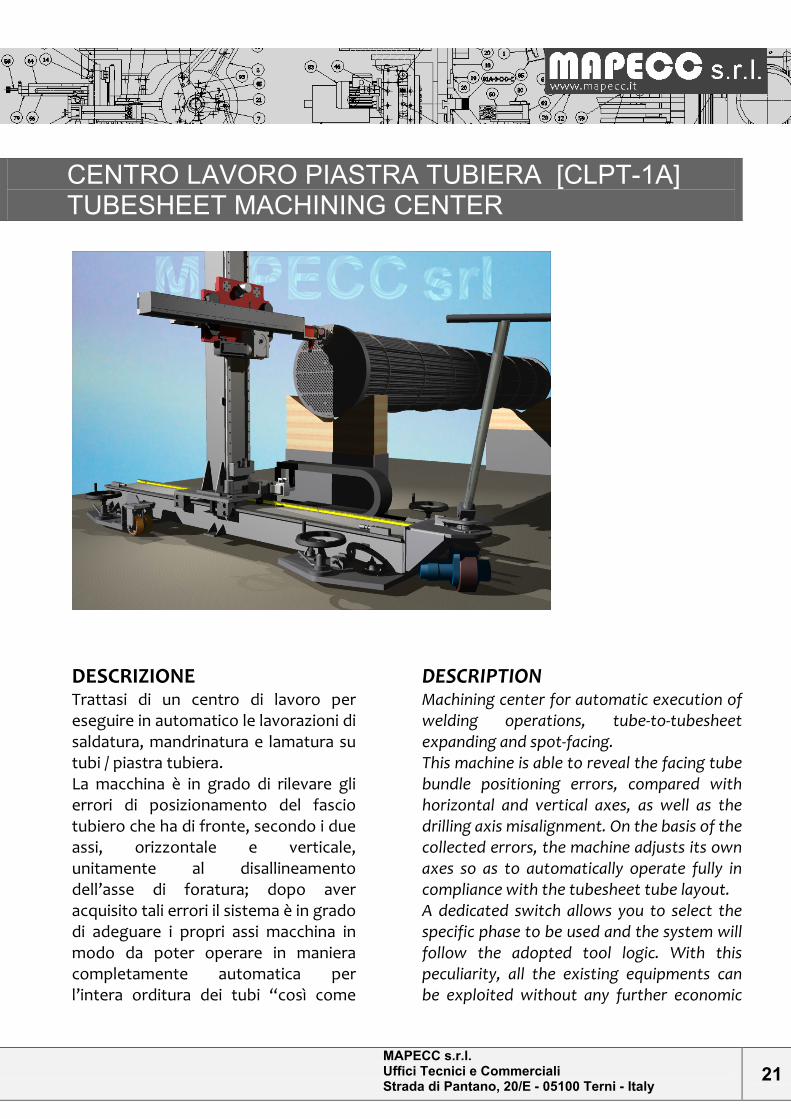
CENTRO LAVORO PIASTRA TUBIERA [CLPT-1A] TUBESHEET MACHINING CENTER
DESCRIZIONE
Trattasi di un centro di lavoro per eseguire in automatico le lavorazioni di saldatura, mandrinatura e lamatura su tubi / piastra tubiera. La macchina è in grado di rilevare gli errori di posizionamento del fascio tubiero che ha di fronte, secondo i due assi, orizzontale e verticale, unitamente al disallineamento dell’asse di foratura; dopo aver acquisito tali errori il sistema è in grado di adeguare i propri assi macchina in modo da poter operare in maniera completamente automatica per l’intera orditura dei tubi “così come
DESCRIPTION
Machining center for automatic execution of welding operations, tube-to-tubesheet expanding and spot-facing. This machine is able to reveal the facing tube bundle positioning errors, compared with horizontal and vertical axes, as well as the drilling axis misalignment. On the basis of the collected errors, the machine adjusts its own axes so as to automatically operate fully in compliance with the tubesheet tube layout. A dedicated switch allows you to select the specific phase to be used and the system will follow the adopted tool logic. With this peculiarity, all the existing equipments can be exploited without any further economic
MAPECC s.r.l. Uffici Tecnici e Commerciali Strada di Pantano, 20/E - 05100 Terni - Italy
22
trovansi” della piastra tubiera in oggetto. Un sezionatore dedicato sarà in grado di selezionare la fase specifica che si intende utilizzare e il sistema seguirà la logica delle attrezzature utilizzate. Questa peculiarità consente di sfruttare tutte le attrezzature esistenti in officina senza ulteriori impegni economici e sfruttando il background acquisito su tali macchine. Queste attrezzature sono comunque da noi fornibili “ex novo” e asservite in loco, bloccaggio principale compreso. (Leggi: saldatrice orbitale / mandrinatrice / lamatrice).
impact and taking advantage of the acquired background on such machines. We can supply these machines ex novo and set them up in loco, main locking included (such as Orbital welding machine/Expanding machine/Spot-facing machine).
MODALITA’ OPERATIVE
1) Posizionare la macchina, dotata di motoruota, di fronte al fascio da lavorare e stabilizzarla a terra tramite i quattro volantini alla base; attrezzare la macchina con la staffa idonea a supportare l’attrezzatura specifica per la lavorazione richiesta; montare su questa il rilevatore di posizione assi. 2) Procedere con la rilevazione dell’inclinazione della faccia della piastra tubiera secondo i piani orizzontale e verticale, per poi procedere alla rilevazione dell’orientamento asse fori sfruttando una coppia di fori perimetrali contrapposti. 3) Procedere all’immissione dei dati piastra tubiera con file formato CSV a percorso programmato, fare una/due prove per definizione parametri lavoro, dopodiché si è pronti ad andare in automatico.
OPERATING INSTRUCTIONS
1) Place the machine, with driving wheel, in front of the tube bundle to be machined, and stabilize it to the ground through the four base handwheels. Equip the machine with the proper bracket, in order to support the specific tool for the required operation. Mount the axis position detector. 2) Proceed with tubesheet face inclination locating, along horizontal and vertical plane, then proceed with hole axis orientation determination, referring to a pair of perimetrical opposite holes. 3) Proceed with the tubesheet data entry through a programmed path.csv file; test once/twice the system in order to define the operating parameters, then the machine can proceed automatically.
MAPECC s.r.l. Uffici Tecnici e Commerciali Strada di Pantano, 20/E - 05100 Terni - Italy
23
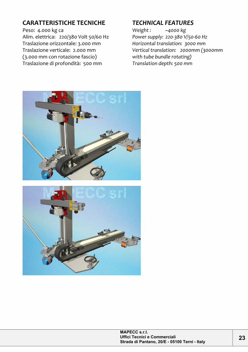
CARATTERISTICHE TECNICHE
Peso: 4.000 kg ca Alim. elettrica: 220/380 Volt 50/60 Hz Traslazione orizzontale: 3.000 mm Traslazione verticale: 2.000 mm (3.000 mm con rotazione fascio) Traslazione di profondità: 500 mm
TECHNICAL FEATURES
Weight : ~4000 kg Power supply: 220-380 V/50-60 Hz Horizontal translation: 3000 mm Vertical translation: 2000mm (3000mm with tube bundle rotating) Translation depth: 500 mm
MAPECC s.r.l. Uffici Tecnici e Commerciali Strada di Pantano, 20/E - 05100 Terni - Italy
24
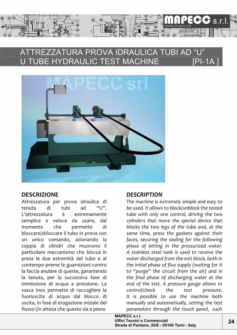
ATTREZZATURA PROVA IDRAULICA TUBI AD “U” U TUBE HYDRAULIC TEST MACHINE [PI-1A ]
DESCRIZIONE Attrezzatura per prova idraulica di tenuta di tubi ad “U”. L’attrezzatura è estremamente semplice e veloce da usare, dal momento che permette di bloccare/sbloccare il tubo in prova con un unico comando, azionando la coppia di cilindri che muovono il particolare meccanismo che blocca in presa le due estremità del tubo e al contempo preme le guarnizioni contro la faccia anulare di queste, garantendo la tenuta, per la successiva fase di immissione di acqua a pressione. La vasca inox permette di raccogliere la fuoriuscita di acqua dal blocco di uscita, in fase di erogazione iniziale del flusso (in attesa che questo sia a pieno
DESCRIPTION
The machine is extremely simple and easy to be used. It allows to block/unblock the tested tube with only one control, driving the two cylinders that move the special device that blocks the two legs of the tube and, at the same time, press the gaskets against their faces, securing the sealing for the following phase of letting in the pressurized water. A stainless steel tank is used to receive the water discharged from the exit block, both in the initial phase of flux supply (waiting for it to “purge” the circuit from the air) and in the final phase of discharging water at the end of the test. A pressure gauge allows to control/check the test pressure. It is possible to use the machine both manually and automatically, setting the test parameters through the touch panel, such
MAPECC s.r.l. Uffici Tecnici e Commerciali Strada di Pantano, 20/E - 05100 Terni - Italy
25
regime e “spurghi” l’ aria nel circuito) e in fase di scarico a prova terminata. Un manometro permette di controllare/verificare la pressione di prova. Possibilità di usare l’attrezzatura sia in manuale che in automatico, previa impostazione dei parametri di prova, tramite l’apposito touch panel, quali: -Pressione di spinta dei cilindri idraulici di serraggio tubo. -Pressione di prova idraulica (… fino a 70 bar). -Tempi di mantenimento pressione di prova.
MODALITA’ OPERATIVE 1.Eventuale sostituzione morse serraggio estremità tubo (in base al diametro di questo). 2.Regolazione dell’interasse dei due blocchi di presa lungo la slitta, in base alle dimensioni della serie di forcelle da testare. 3.Inserimento del tubo da testare nelle bocche dei blocchi di presa. 4.Prima sequenza manuale per la definizione dei parametri di prova a.Azionamento dei cilindri (simultaneo) per blocco delle estremità tubo. b.Immissione acqua e mantenimento alla pressione e per il tempo prescritti; verifica del mantenimento/perdite (feedback da touch panel in caso di prova fallita). c.Scarico acqua. d.Azionamento dei cilindri per sblocco tubo. 5.Sfilaggio del tubo. Le successive prove su altri tubi ad U di stesse dimensioni, si possono a questo punto eseguire in automatico, limitandosi a: -Inserimento del tubo. -Start sequenza di prova da touch panel. -Sfilaggio tubo.
as: -the pushing pressure of the hydraulic cylinders that tighten the tubes -the hydraulic test pressure (up to 70 bar) -duration of test pressure maintenance.
OPERATING INSTRUCTIONS
1.Replacement, if needed, of the tube leg tightening vice (depending on the tube diameter) 2.Regulation of the center-to-center distance of the two grip blocks along the guide, on the basis of the dimensions of the series of the U tubes to be tested. 3.Fitting of the tube to be tested into the jaws of the grip blocks. 4.First manual sequence for test parameter setting: a.Working of the cylinders (simultaneous) to block the legs of the tube. b.Letting in of the water and keeping the pressure constant for the required time; check of the pressure drop, if any (feedback from touch panel in case of failed test). c.Water discharging. d.Working of the cylinders for tube unblocking. e.Tube removal. The test of the other tubes of the same dimensions can be performed automatically, in this way: a.Fitting of the tube. b.Staring of the test sequence through the touch panel.
MAPECC s.r.l. Uffici Tecnici e Commerciali Strada di Pantano, 20/E - 05100 Terni - Italy
26
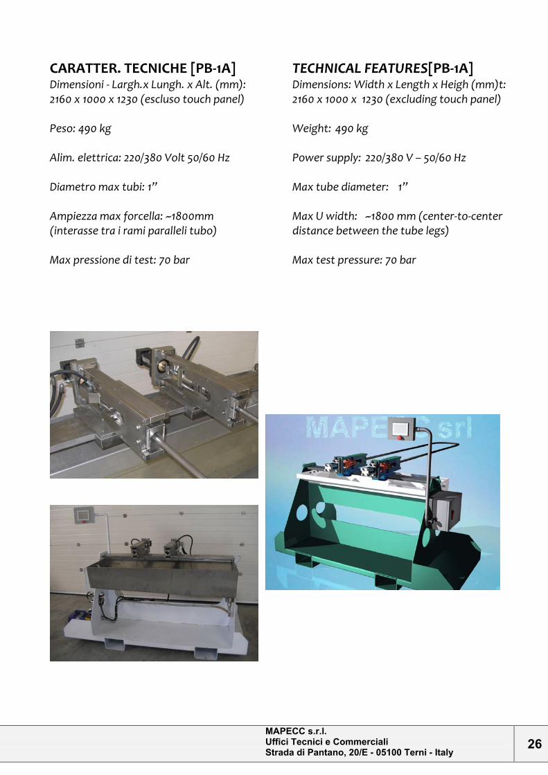
CARATTER. TECNICHE [PB-1A] Dimensioni - Largh.x Lungh. x Alt. (mm): 2160 x 1000 x 1230 (escluso touch panel) Peso: 490 kg Alim. elettrica: 220/380 Volt 50/60 Hz Diametro max tubi: 1” Ampiezza max forcella: ~1800mm (interasse tra i rami paralleli tubo) Max pressione di test: 70 bar
TECHNICAL FEATURES[PB-1A] Dimensions: Width x Length x Heigh (mm)t: 2160 x 1000 x 1230 (excluding touch panel) Weight: 490 kg Power supply: 220/380 V – 50/60 Hz Max tube diameter: 1” Max U width: ~1800 mm (center-to-center distance between the tube legs) Max test pressure: 70 bar
MAPECC s.r.l. Uffici Tecnici e Commerciali Strada di Pantano, 20/E - 05100 Terni - Italy
27
MACCHINA DI TAGLIO ORBITALE ORBITAL DRILLING MACHINE [FO-1A]
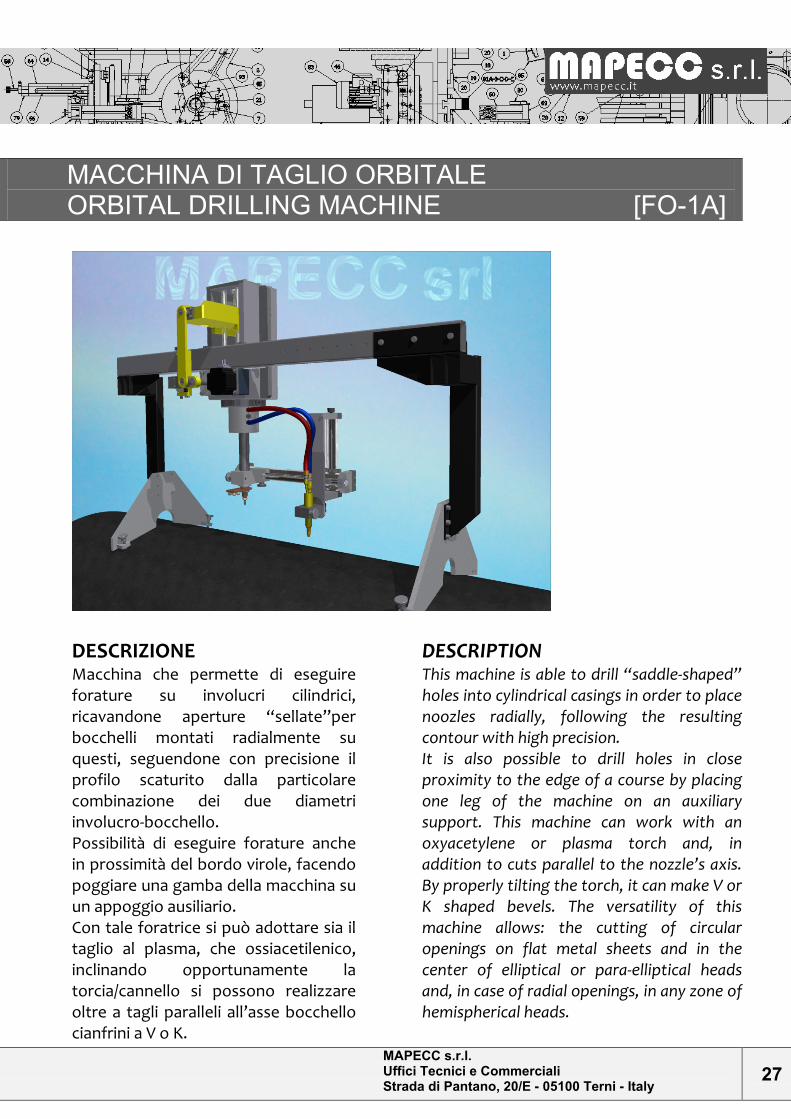
DESCRIZIONE
Macchina che permette di eseguire forature su involucri cilindrici, ricavandone aperture “sellate”per bocchelli montati radialmente su questi, seguendone con precisione il profilo scaturito dalla particolare combinazione dei due diametri involucro-bocchello. Possibilità di eseguire forature anche in prossimità del bordo virole, facendo poggiare una gamba della macchina su un appoggio ausiliario. Con tale foratrice si può adottare sia il taglio al plasma, che ossiacetilenico, inclinando opportunamente la torcia/cannello si possono realizzare oltre a tagli paralleli all’asse bocchello cianfrini a V o K.
DESCRIPTION
This machine is able to drill “saddle-shaped” holes into cylindrical casings in order to place noozles radially, following the resulting contour with high precision. It is also possible to drill holes in close proximity to the edge of a course by placing one leg of the machine on an auxiliary support. This machine can work with an oxyacetylene or plasma torch and, in addition to cuts parallel to the nozzle’s axis. By properly tilting the torch, it can make V or K shaped bevels. The versatility of this machine allows: the cutting of circular openings on flat metal sheets and in the center of elliptical or para-elliptical heads and, in case of radial openings, in any zone of hemispherical heads.
MAPECC s.r.l. Uffici Tecnici e Commerciali Strada di Pantano, 20/E - 05100 Terni - Italy
28
Naturalmente la versatilità della macchina permette il taglio di aperture circolari su lamiere piane e al centro di fonti ellittici, paraellittici e similari, nonché, nel caso di aperture/bocchelli radiali, in qualsiasi zona di fondi emisferici.
MODALITA’ OPERATIVE
-Posizionamento: Una volta che l’apertura é stata tracciata sull’involucro, va posizionata la macchina, allineandone gli appoggi sulla tracciatura longitudinale e centrata all'incirca longitudinalmente: la regolazione precisa verrà poi eseguita facendo scorrere il corpo macchina sulla slitta del telaio, traguardando l’apposito puntatore assiale fatto opportunamente scendere, che indicherà l’asse dell’apertura da eseguire. -Impostazione: Con macchina a corsa glifo pari a zero e braccio porta utensile di taglio a rotazione 0°, posizione corrispondente a torcia coincidente con la tracciatura longitudinale, verrà posizionata l’attrezzatura di taglio a distanza e altezza desiderate, tramite l’apposita doppia slitta di regolazione. Si azionerà quindi la macchina per far compiere al braccio una rotazione di 90°, coincidente al punto minimo di sellatura; qui si regolerà la corsa glifo portando la torcia/cannello nel punto che si vorrà assumere come punto di taglio in questo punto. Si farà la lettura di tale corsa sulla scala graduata del glifo e la si imposterà dimezzata. Una volta riportata la macchina a rotazione 0, va aggiustata definitivamente l’altezza dell’attrezzatura di taglio (agendo sulla slitta verticale della doppia slitta) e questa e’ pronta per il taglio; tramite pannello di controllo sarà possibile regolare la velocità di rotazione.
OPERATING INSTRUCTIONS
Positioning: After the opening has been traced on the cylindrical casing, the machine will be positioned by aligning its supports on the tracking and centered longitudinally: the fine tuning is then performed by moving the machine’s body on the slide frame until the axial pointer will mark the axis of the hole. Setting Having the glyph and the tool holder arm in their rest position (with glyph stroke at zero and the torch coincident with the longitudinal tracing) it is possible to set the cutting equipment to the desired position (distance and height), by shifting it through the double slide. The machine operates by turning the tool holder arm 90 degrees, coincident to the lowest point of the saddle, and then it regulates the glyph bearing the torch to the point where the cut has to take place. Read the excursion on the scale of the glyph and set the machine considering one half of it. When the machine is set back to the rest position, the height of the cutting equipment (by acting on the vertical double slide), must be adjusted. Now the machine is ready to start cutting the “saddle-shaped" holes. It is possible to adjust the speed of rotation by means of the control panel.
MAPECC s.r.l. Uffici Tecnici e Commerciali Strada di Pantano, 20/E - 05100 Terni - Italy
29
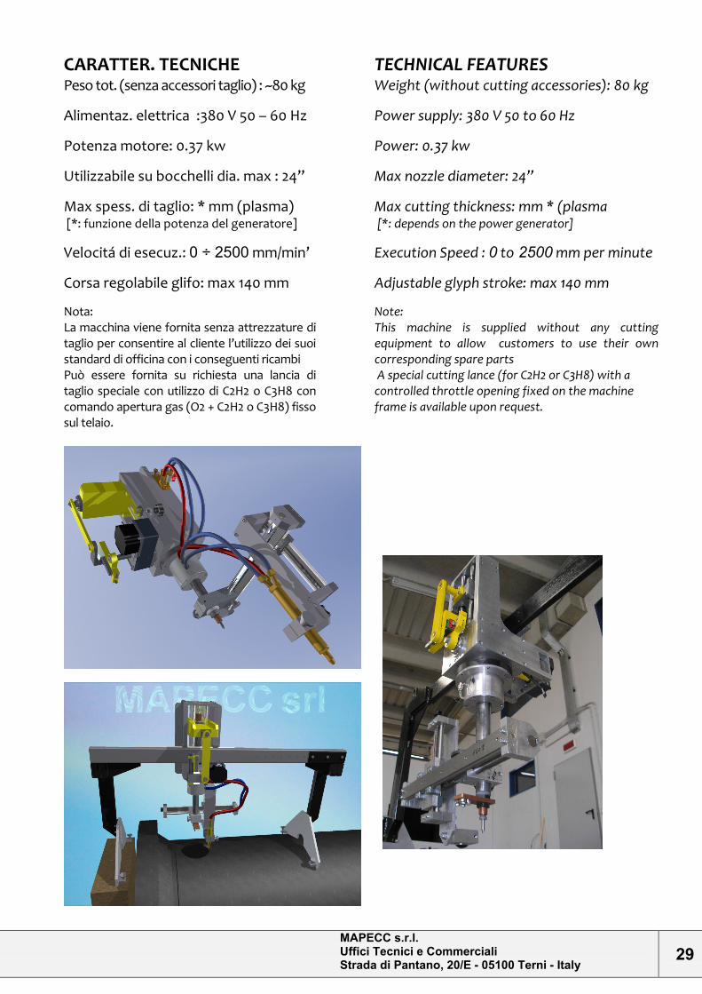
CARATTER. TECNICHE
Peso tot. (senza accessori taglio) : ~80 kg
Alimentaz. elettrica :380 V 50 – 60 Hz
Potenza motore: 0.37 kw
Utilizzabile su bocchelli dia. max : 24”
Max spess. di taglio: * mm (plasma) [*: funzione della potenza del generatore]
Velocitá di esecuz.: 0 ÷ 2500 mm/min’
Corsa regolabile glifo: max 140 mm
Nota: La macchina viene fornita senza attrezzature di taglio per consentire al cliente l’utilizzo dei suoi standard di officina con i conseguenti ricambi Può essere fornita su richiesta una lancia di taglio speciale con utilizzo di C2H2 o C3H8 con comando apertura gas (O2 + C2H2 o C3H8) fisso sul telaio.
TECHNICAL FEATURES
Weight (without cutting accessories): 80 kg
Power supply: 380 V 50 to 60 Hz
Power: 0.37 kw
Max nozzle diameter: 24”
Max cutting thickness: mm * (plasma [*: depends on the power generator]
Execution Speed : 0 to 2500 mm per minute
Adjustable glyph stroke: max 140 mm
Note: This machine is supplied without any cutting equipment to allow customers to use their own corresponding spare parts A special cutting lance (for C2H2 or C3H8) with a controlled throttle opening fixed on the machine frame is available upon request.
MAPECC s.r.l. Uffici Tecnici e Commerciali Strada di Pantano, 20/E - 05100 Terni - Italy
30
CENTRO BOCCHELLI [CB-1A] EQUIPMENT FOR NOZZLES AND PIPES MANUFACT.
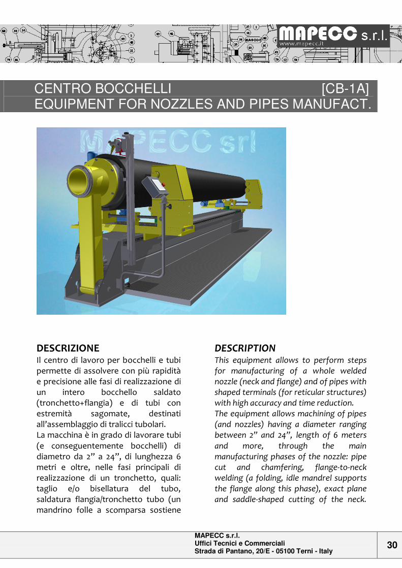
DESCRIZIONE Il centro di lavoro per bocchelli e tubi permette di assolvere con più rapidità e precisione alle fasi di realizzazione di un intero bocchello saldato (tronchetto+flangia) e di tubi con estremità sagomate, destinati all’assemblaggio di tralicci tubolari. La macchina è in grado di lavorare tubi (e conseguentemente bocchelli) di diametro da 2” a 24”, di lunghezza 6 metri e oltre, nelle fasi principali di realizzazione di un tronchetto, quali: taglio e/o bisellatura del tubo, saldatura flangia/tronchetto tubo (un mandrino folle a scomparsa sostiene
DESCRIPTION This equipment allows to perform steps for manufacturing of a whole welded nozzle (neck and flange) and of pipes with shaped terminals (for reticular structures) with high accuracy and time reduction. The equipment allows machining of pipes (and nozzles) having a diameter ranging between 2” and 24”, length of 6 meters and more, through the main manufacturing phases of the nozzle: pipe cut and chamfering, flange-to-neck welding (a folding, idle mandrel supports the flange along this phase), exact plane and saddle-shaped cutting of the neck.
MAPECC s.r.l. Uffici Tecnici e Commerciali Strada di Pantano, 20/E - 05100 Terni - Italy
31
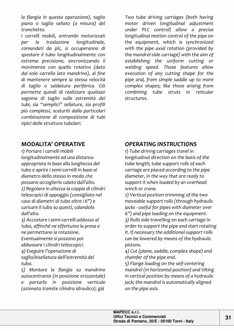
la flangia in questa operazione), taglio piano o taglio sellato (a misura) del tronchetto. I carrelli mobili, entrambi motorizzati per la traslazione longitudinale, comandati da plc, si occuperanno di spostare il tubo longitudinalmente con estrema precisione, sincronizzando il movimento con quello rotativo (dato dal solo carrello lato mandrino), al fine di mantenere sempre la stessa velocità di taglio o saldatura periferica. Ciò permette quindi di realizzare qualsiasi sagoma di taglio sulle estremità dei tubi, sia “semplici” sellature, sia profili più complessi, scaturiti dalla particolari combinazione di composizione di tubi tipici delle strutture tubolari.
Two tube driving carriages (both having motor driven longitudinal adjustment under PLC control) allow a precise longitudinal motion control of the pipe on the equipment, which is synchronized with the pipe axial rotation (provided by the mandrel-side carriage) with the aim of establishing the uniform cutting or welding speed. Those features allow execution of any cutting shape for the pipe and, from simple saddle up to more complex shapes; like those arising from combining tube struts in reticular structures.
MODALITA’ OPERATIVE 1) Portare i carrelli mobili longitudinalmente ad una distanza appropriata in base alla lunghezza del tubo e aprire i semi-carrelli in base al diametro dello stesso in modo che possano accoglierlo calato dall’alto. 2) Regolare in altezza la coppia di cilindri telescopici di appoggio (consigliato nel caso di diametri di tubo oltre i 6”) e caricare il tubo su questi, calandolo dall’alto. 3) Accostare i semi-carrelli addosso al tubo, affinché ne effettuino la presa e ne permettano la rotazione. Eventualmente si possono poi abbassare i cilindri telescopici. 4) Eseguire l’operazione di taglio/bisellatura dell’estremità del tubo. 5) Montare la flangia su mandrino autocentrante (in posizione orizzontale) e portarlo in posizione verticale (azionato tramite cilindro idraulico), già
OPERATING INSTRUCTIONS 1) Tube driving carriages travel in longitudinal direction on the basis of the tube length; tube support rolls of each carriage are placed according to the pipe diameter, in the way that are ready to support it when loaded by an overhead winch or crane. 2) Vertical position trimming of the two moveable support rolls (through hydraulic jacks - useful for pipes with diameter over 6”) and pipe loading on the equipment. 3) Rolls side travelling on each carriage in order to support the pipe and start rotating it. If necessary the additional support rolls can be lowered by means of the hydraulic pistons. 4) Cut (plane, saddle, complex shape) and chamfer of the pipe end. 5) Flange loading on the self-centering mandrel (in horizontal position) and tilting in vertical position by means of a hydraulic jack; the mandrel is automatically aligned on the pipe axis.
MAPECC s.r.l. Uffici Tecnici e Commerciali Strada di Pantano, 20/E - 05100 Terni - Italy
32
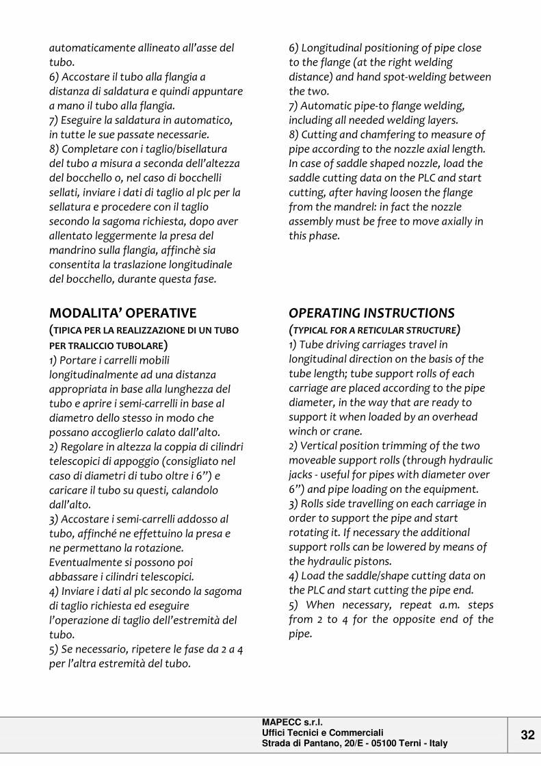
automaticamente allineato all’asse del tubo. 6) Accostare il tubo alla flangia a distanza di saldatura e quindi appuntare a mano il tubo alla flangia. 7) Eseguire la saldatura in automatico, in tutte le sue passate necessarie. 8) Completare con i taglio/bisellatura del tubo a misura a seconda dell’altezza del bocchello o, nel caso di bocchelli sellati, inviare i dati di taglio al plc per la sellatura e procedere con il taglio secondo la sagoma richiesta, dopo aver allentato leggermente la presa del mandrino sulla flangia, affinchè sia consentita la traslazione longitudinale del bocchello, durante questa fase.
MODALITA’ OPERATIVE (TIPICA PER LA REALIZZAZIONE DI UN TUBO
PER TRALICCIO TUBOLARE) 1) Portare i carrelli mobili longitudinalmente ad una distanza appropriata in base alla lunghezza del tubo e aprire i semi-carrelli in base al diametro dello stesso in modo che possano accoglierlo calato dall’alto. 2) Regolare in altezza la coppia di cilindri telescopici di appoggio (consigliato nel caso di diametri di tubo oltre i 6”) e caricare il tubo su questi, calandolo dall’alto. 3) Accostare i semi-carrelli addosso al tubo, affinché ne effettuino la presa e ne permettano la rotazione. Eventualmente si possono poi abbassare i cilindri telescopici. 4) Inviare i dati al plc secondo la sagoma di taglio richiesta ed eseguire l’operazione di taglio dell’estremità del tubo. 5) Se necessario, ripetere le fase da 2 a 4 per l’altra estremità del tubo.
6) Longitudinal positioning of pipe close to the flange (at the right welding distance) and hand spot-welding between the two. 7) Automatic pipe-to flange welding, including all needed welding layers. 8) Cutting and chamfering to measure of pipe according to the nozzle axial length. In case of saddle shaped nozzle, load the saddle cutting data on the PLC and start cutting, after having loosen the flange from the mandrel: in fact the nozzle assembly must be free to move axially in this phase.
OPERATING INSTRUCTIONS (TYPICAL FOR A RETICULAR STRUCTURE) 1) Tube driving carriages travel in longitudinal direction on the basis of the tube length; tube support rolls of each carriage are placed according to the pipe diameter, in the way that are ready to support it when loaded by an overhead winch or crane. 2) Vertical position trimming of the two moveable support rolls (through hydraulic jacks - useful for pipes with diameter over 6”) and pipe loading on the equipment. 3) Rolls side travelling on each carriage in order to support the pipe and start rotating it. If necessary the additional support rolls can be lowered by means of the hydraulic pistons. 4) Load the saddle/shape cutting data on the PLC and start cutting the pipe end. 5) When necessary, repeat a.m. steps from 2 to 4 for the opposite end of the pipe.
MAPECC s.r.l. Uffici Tecnici e Commerciali Strada di Pantano, 20/E - 05100 Terni - Italy
33
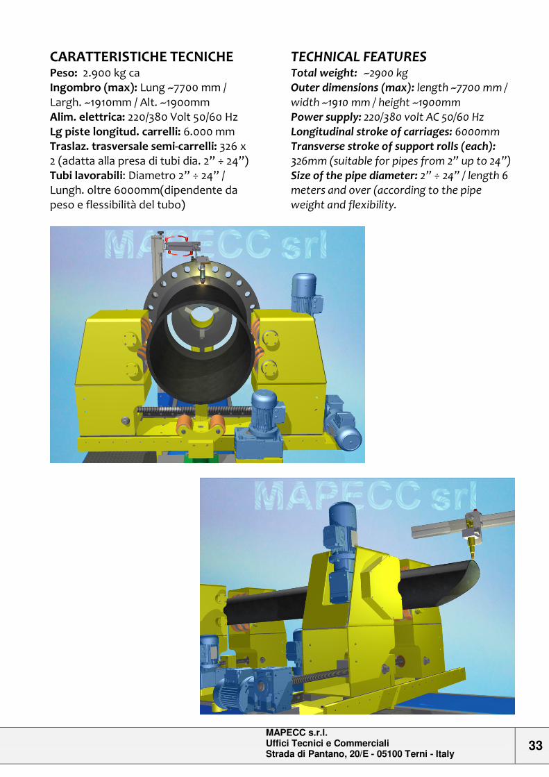
CARATTERISTICHE TECNICHE
Peso: 2.900 kg ca Ingombro (max): Lung ~7700 mm / Largh. ~1910mm / Alt. ~1900mm Alim. elettrica: 220/380 Volt 50/60 Hz Lg piste longitud. carrelli: 6.000 mm Traslaz. trasversale semi-carrelli: 326 x 2 (adatta alla presa di tubi dia. 2” ÷ 24”) Tubi lavorabili: Diametro 2” ÷ 24” / Lungh. oltre 6000mm(dipendente da peso e flessibilità del tubo)
TECHNICAL FEATURES
Total weight: ~2900 kg Outer dimensions (max): length ~7700 mm / width ~1910 mm / height ~1900mm Power supply: 220/380 volt AC 50/60 Hz Longitudinal stroke of carriages: 6000mm Transverse stroke of support rolls (each): 326mm (suitable for pipes from 2” up to 24”) Size of the pipe diameter: 2” ÷ 24” / length 6 meters and over (according to the pipe weight and flexibility.
MAPECC s.r.l. Uffici Tecnici e Commerciali Strada di Pantano, 20/E - 05100 Terni - Italy
34
SALDATRICE ORBITALE [SOC-1A] COMPACT ORBITAL WELDING MACHINE
DESCRIZIONE
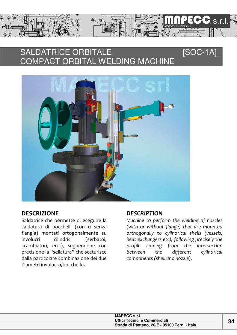
Saldatrice che permette di eseguire la saldatura di bocchelli (con o senza flangia) montati ortogonalmente su involucri cilindrici (serbatoi, scambiatori, ecc.), seguendone con precisione la “sellatura” che scaturisce dalla particolare combinazione dei due diametri involucro/bocchello.
DESCRIPTION
Machine to perform the welding of nozzles (with or without flange) that are mounted orthogonally to cylindrical shells (vessels, heat exchangers etc), following precisely the profile coming from the intersection between the different cylindrical components (shell and nozzle).
MAPECC s.r.l. Uffici Tecnici e Commerciali Strada di Pantano, 20/E - 05100 Terni - Italy
35
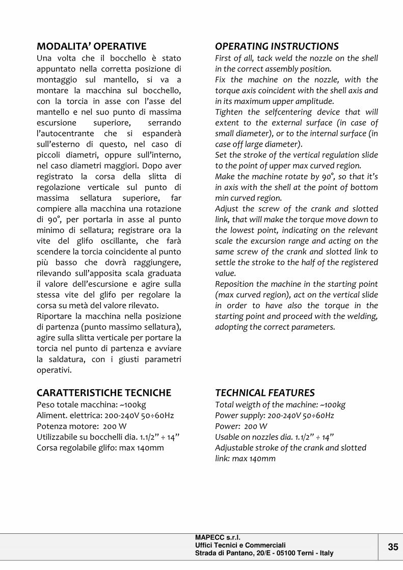
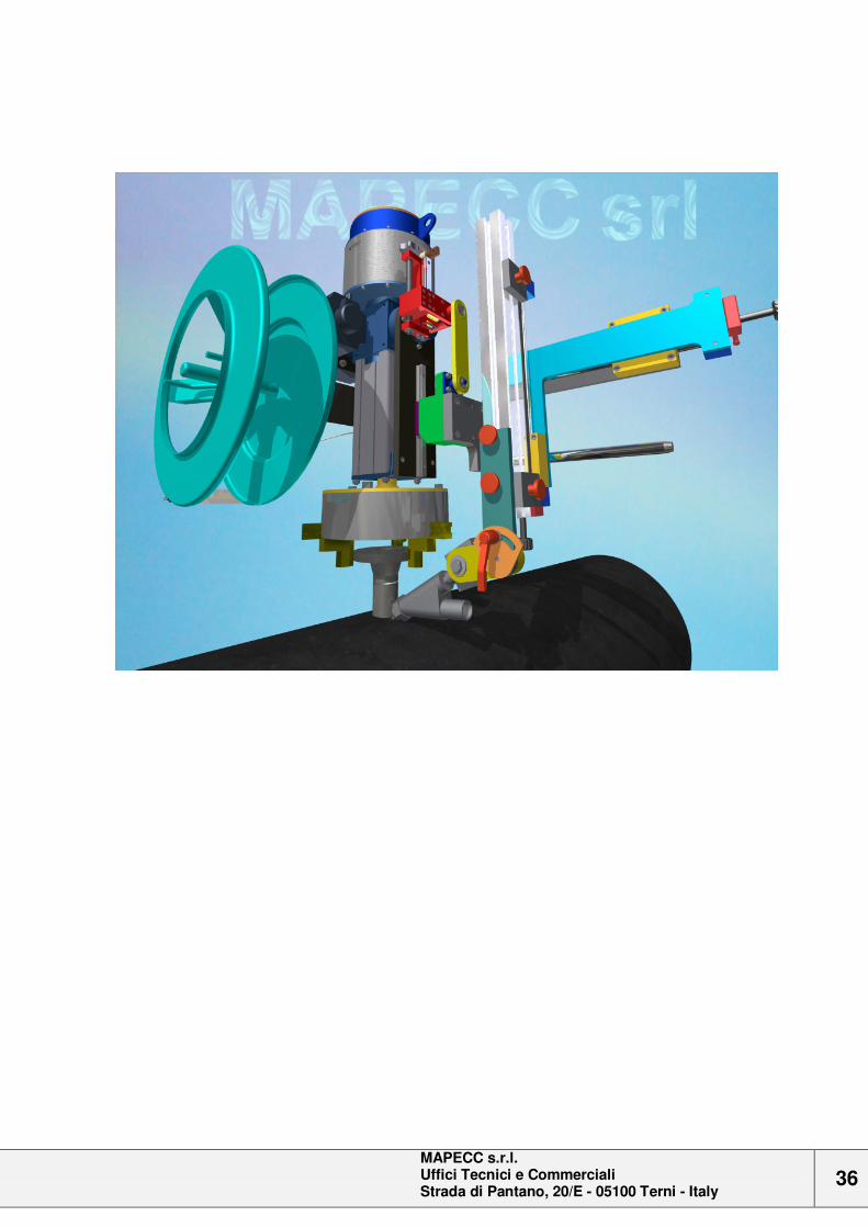
MODALITA’ OPERATIVE
Una volta che il bocchello è stato appuntato nella corretta posizione di montaggio sul mantello, si va a montare la macchina sul bocchello, con la torcia in asse con l’asse del mantello e nel suo punto di massima escursione superiore, serrando l’autocentrante che si espanderà sull’esterno di questo, nel caso di piccoli diametri, oppure sull’interno, nel caso diametri maggiori. Dopo aver registrato la corsa della slitta di regolazione verticale sul punto di massima sellatura superiore, far compiere alla macchina una rotazione di 90°, per portarla in asse al punto minimo di sellatura; registrare ora la vite del glifo oscillante, che farà scendere la torcia coincidente al punto più basso che dovrà raggiungere, rilevando sull’apposita scala graduata il valore dell’escursione e agire sulla stessa vite del glifo per regolare la corsa su metà del valore rilevato. Riportare la macchina nella posizione di partenza (punto massimo sellatura), agire sulla slitta verticale per portare la torcia nel punto di partenza e avviare la saldatura, con i giusti parametri operativi.
OPERATING INSTRUCTIONS
First of all, tack weld the nozzle on the shell in the correct assembly position. Fix the machine on the nozzle, with the torque axis coincident with the shell axis and in its maximum upper amplitude. Tighten the selfcentering device that will extent to the external surface (in case of small diameter), or to the internal surface (in case off large diameter). Set the stroke of the vertical regulation slide to the point of upper max curved region. Make the machine rotate by 90°, so that it’s in axis with the shell at the point of bottom min curved region. Adjust the screw of the crank and slotted link, that will make the torque move down to the lowest point, indicating on the relevant scale the excursion range and acting on the same screw of the crank and slotted link to settle the stroke to the half of the registered value. Reposition the machine in the starting point (max curved region), act on the vertical slide in order to have also the torque in the starting point and proceed with the welding, adopting the correct parameters.
CARATTERISTICHE TECNICHE
Peso totale macchina: ~100kg Aliment. elettrica: 200-240V 50÷60Hz Potenza motore: 200 W Utilizzabile su bocchelli dia. 1.1/2” ÷ 14” Corsa regolabile glifo: max 140mm
TECHNICAL FEATURES
Total weigth of the machine: ~100kg Power supply: 200-240V 50÷60Hz Power: 200 W Usable on nozzles dia. 1.1/2” ÷ 14” Adjustable stroke of the crank and slotted link: max 140mm
MAPECC s.r.l. Uffici Tecnici e Commerciali Strada di Pantano, 20/E - 05100 Terni - Italy
36
MAPECC s.r.l.
Commercial and Technical offices Strada di Pantano, 20/E - 05100 Terni – Italy Phone +39-0744-817141 Fax +39-0744-807591 Technical mail: [email protected] Commercial mail: [email protected]