Embed Size (px)
Citation preview
SONIC MAXIMIZER
482User Guide
and Reference Manual
i
1
Important Safeguards ……………………………………………………………………………………………………………iBBE Process Explained …………………………………………………………………………………………………………1-2Product Description ………………………………………………………………………………………………………………2Applications ………………………………………………………………………………………………………………………2Controls and Connections ………………………………………………………………………………………………………3Specifications ………………………………………………………………………………………………………………………4General Operation ………………………………………………………………………………………………………………4Application Diagrams …………………………………………………………………………………………………………5-9Service /Warranty / Maintenance ……………………………………………………………………………………………10Calibration Procedures …………………………………………………………………………………………………………11Schematic Diagrams…………………………………………………………………………………………………………12-15
Congratulations on your purchase of the BBE 482 Sonic Maximizer—a two channel signal processor
that will benefit any recording or sound reproduction system. You now own a very unique signal
processing device with no equal in the audio world. Whether you purchased the BBE 482 for your
home studio, P.A., DJ system, or instrument rack, you will find the 482's rugged construction and
careful electronic design a welcome addition to your sonic arsenal.
Thank you for your purchase, and for the trust that you've placed in BBE. We are committed to
bringing you the finest products, with useful and unique features to serve your audio needs.
The BBE Process—"What it Is"Loudspeakers have difficulty working with the electronic signals supplied by an amplifier. These difficulties cause suchmajor phase and amplitude distortion that the sound reproduced by speaker differs significantly from the soundproduced by the original source.
In the past, these problems proved unsolvable and were thus delegated to a position of secondary importance in audiosystem design. However, phase and amplitude integrity is essential to accurate sound reproduction. Research showsthat the information which the listener translates into the recognizable characteristics of a live performance areintimately tied into complex time and amplitude relationships between the fundamental and harmonic componentsof a given musical note or sound. These relationships define a sound's “sound”.
When these complex relationships pass through a speaker, the proper order is lost. The higher frequencies are delayed.A lower frequency may reach the listener's ear first or perhaps simultaneously with that of a higher frequency. In somecases, the fundamental components may be so time-shifted that they reach the listener's ear ahead of some or all ofthe harmonic components.
This change in the phase and amplitude relationship on the harmonic and fundamental frequencies is technicallycalled “envelope distortion.” The listener perceives this loss of sound integrity in the reproduced sound as "muddy"and “smeared.” In the extreme, it can become difficult to tell the difference between musical instruments, for example,an oboe and a clarinet.
BBE Sound, Inc. conducted extensive studies of numerous speaker systems over a ten year period. With this knowledge,it became possible to identify the characteristics of an ideal speaker and to distill the corrections necessary to returnthe fundamental and harmonic frequency structures to their correct order. While there are differences among variousspeaker designs in the magnitude of their correction, the overall pattern of correction needed is remarkably consistent.
The BBE Process is so unique that 42 patents have been awarded by the U.S. Patent Office.
TABLE OF CONTENTS
Product Description
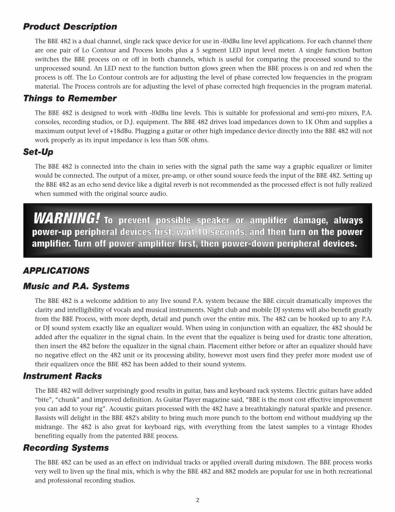
The BBE 482 is a dual channel, single rack space device for use in -l0dBu line level applications. For each channel thereare one pair of Lo Contour and Process knobs plus a 5 segment LED input level meter. A single function buttonswitches the BBE process on or off in both channels, which is useful for comparing the processed sound to theunprocessed sound. An LED next to the function button glows green when the BBE process is on and red when theprocess is off. The Lo Contour controls are for adjusting the level of phase corrected low frequencies in the programmaterial. The Process controls are for adjusting the level of phase corrected high frequencies in the program material.
Things to Remember
The BBE 482 is designed to work with -l0dBu line levels. This is suitable for professional and semi-pro mixers, P.A.consoles, recording studios, or D.J. equipment. The BBE 482 drives load impedances down to 1K Ohm and supplies amaximum output level of +18dBu. Plugging a guitar or other high impedance device directly into the BBE 482 will notwork properly as its input impedance is less than 50K ohms.
Set-Up
The BBE 482 is connected into the chain in series with the signal path the same way a graphic equalizer or limiterwould be connected. The output of a mixer, pre-amp, or other sound source feeds the input of the BBE 482. Setting upthe BBE 482 as an echo send device like a digital reverb is not recommended as the processed effect is not fully realizedwhen summed with the original source audio.
APPLICATIONS
Music and P.A. Systems
The BBE 482 is a welcome addition to any live sound P.A. system because the BBE circuit dramatically improves theclarity and intelligibility of vocals and musical instruments. Night club and mobile DJ systems will also benefit greatlyfrom the BBE Process, with more depth, detail and punch over the entire mix. The 482 can be hooked up to any P.A.or DJ sound system exactly like an equalizer would. When using in conjunction with an equalizer, the 482 should beadded after the equalizer in the signal chain. In the event that the equalizer is being used for drastic tone alteration,then insert the 482 before the equalizer in the signal chain. Placement either before or after an equalizer should haveno negative effect on the 482 unit or its processing ability, however most users find they prefer more modest use oftheir equalizers once the BBE 482 has been added to their sound systems.
Instrument Racks
The BBE 482 will deliver surprisingly good results in guitar, bass and keyboard rack systems. Electric guitars have added“bite”, “chunk” and improved definition. As Guitar Player magazine said, “BBE is the most cost effective improvementyou can add to your rig”. Acoustic guitars processed with the 482 have a breathtakingly natural sparkle and presence.Bassists will delight in the BBE 482's ability to bring much more punch to the bottom end without muddying up themidrange. The 482 is also great for keyboard rigs, with everything from the latest samples to a vintage Rhodesbenefiting equally from the patented BBE process.
Recording Systems
The BBE 482 can be used as an effect on individual tracks or applied overall during mixdown. The BBE process worksvery well to liven up the final mix, which is why the BBE 482 and 882 models are popular for use in both recreationaland professional recording studios.
2
WWAARRNNIINNGG!! TToo pprreevveenntt ppoossssiibbllee ssppeeaakkeerr oorr aammpplliiffiieerr ddaammaaggee,, aallwwaayyssppoowweerr--uupp ppeerriipphheerraall ddeevviicceess ffiirrsstt,, wwaaiitt 1100 sseeccoonnddss,, aanndd tthheenn ttuurrnn oonn tthhee ppoowweerraammpplliiffiieerr.. TTuurrnn ooffff ppoowweerr aammpplliiffiieerr ffiirrsstt,, tthheenn ppoowweerr--ddoowwnn ppeerriipphheerraall ddeevviicceess..
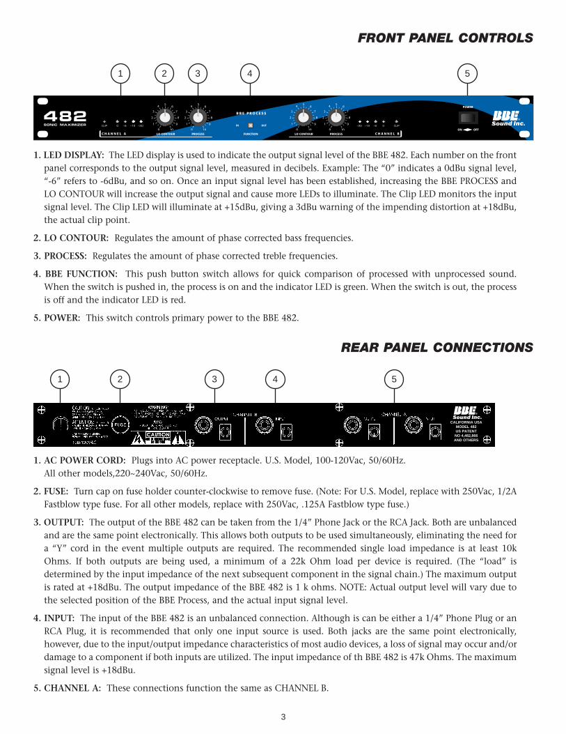
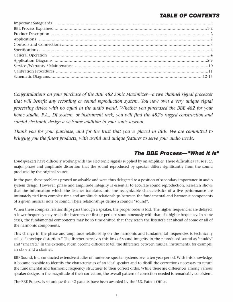
1. LED DISPLAY: The LED display is used to indicate the output signal level of the BBE 482. Each number on the frontpanel corresponds to the output signal level, measured in decibels. Example: The “0” indicates a 0dBu signal level,“-6” refers to -6dBu, and so on. Once an input signal level has been established, increasing the BBE PROCESS andLO CONTOUR will increase the output signal and cause more LEDs to illuminate. The Clip LED monitors the inputsignal level. The Clip LED will illuminate at +15dBu, giving a 3dBu warning of the impending distortion at +18dBu,the actual clip point.
2. LO CONTOUR: Regulates the amount of phase corrected bass frequencies.
3. PROCESS: Regulates the amount of phase corrected treble frequencies.
4. BBE FUNCTION: This push button switch allows for quick comparison of processed with unprocessed sound.When the switch is pushed in, the process is on and the indicator LED is green. When the switch is out, the processis off and the indicator LED is red.
5. POWER: This switch controls primary power to the BBE 482.
REAR PANEL CONNECTIONS
1. AC POWER CORD: Plugs into AC power receptacle. U.S. Model, 100-120Vac, 50/60Hz. All other models,220~240Vac, 50/60Hz.
2. FUSE: Turn cap on fuse holder counter-clockwise to remove fuse. (Note: For U.S. Model, replace with 250Vac, 1/2AFastblow type fuse. For all other models, replace with 250Vac, .125A Fastblow type fuse.)
3. OUTPUT: The output of the BBE 482 can be taken from the 1/4” Phone Jack or the RCA Jack. Both are unbalancedand are the same point electronically. This allows both outputs to be used simultaneously, eliminating the need fora “Y” cord in the event multiple outputs are required. The recommended single load impedance is at least 10kOhms. If both outputs are being used, a minimum of a 22k Ohm load per device is required. (The “load” isdetermined by the input impedance of the next subsequent component in the signal chain.) The maximum outputis rated at +18dBu. The output impedance of the BBE 482 is 1 k ohms. NOTE: Actual output level will vary due tothe selected position of the BBE Process, and the actual input signal level.
4. INPUT: The input of the BBE 482 is an unbalanced connection. Although is can be either a 1/4” Phone Plug or anRCA Plug, it is recommended that only one input source is used. Both jacks are the same point electronically,however, due to the input/output impedance characteristics of most audio devices, a loss of signal may occur and/ordamage to a component if both inputs are utilized. The input impedance of th BBE 482 is 47k Ohms. The maximumsignal level is +18dBu.
5. CHANNEL A: These connections function the same as CHANNEL B.
3
FRONT PANEL CONTROLS
1
1
2
2
3
3
4
4 5
5
C H A N N E L A
-20 -12 -6 0 CLIP-20-12-60CLIP
®
FUNCTION
POWER
ON OFF▼▼IN OUT
B B E P R O C E S S
SONIC MAXIMIZER
482C H A N N E L BLO CONTOUR PROCESS LO CONTOUR PROCESS
CALIFORNIA USAMODEL 482US PATENT
NO 4,482,866AND OTHERS
SpecificationsFrequency Response,
process mode:……………………………Program controlledbypass mode: ……………………………10Hz to 50kHz +/-0.5dBu, -10dBu input
THD, process mode:……………………………less than 0.025% at -10dBu input, 20-20kHzbypass mode: ……………………………less than 0.002% at -l0dBu input, 20-20kHz
Maximum Output: ………………………………+18dBu (may vary due to control settings)Input Impedance: ………………………………47k Ohms, unbalanced 1/4" phone jack or RCA jackOutput Impedance: ……………………………1 k Ohms, unbalanced 1/4" phone jack or RCA jackSensitivity:…………………………………………-45dBu for maximum processMaximum Process: ………………………………+12dBu boost at 5kHz, -l0dBu inputLo Contour: ………………………………………+12dBu boost at 50Hz, -l0dBu input
* 0dBu = 0.775mVrms
Power Requirements: ……………………………U.S., Canada 8 Japan models: 120VAC, 50/60Hz, 8 WATTSStandard model: 220VAC, 50/60Hz, 8 WATTS
Fuse: ………………………………………………Replace with the same type FASTBLOW fuseU.S., Canada & Japan models: 250Vac, 1 /2A Fast blow type fuse.Standard model: 250Vac, .125A Fastblow type fuse
Dimensions: …………………………………...... 19"(W) x 5.5"(D) x 1.7"(H)Shipping Weight: ………………………………6.5 lbs.
Note: Due to continuing product improvement, specifications and design are subject to change without notice.
General Operation
THE BBE 482 IS A LINE LEVEL SIGNAL PROCESSOR AND IS TO BE CONNECTED PRIOR TOTHE POWER AMP IN ANY AUDIO SYSTEM. SIGNIFICANT DAMAGE MAY BE INFLICTED TOTHE BBE 482 OR ANY SUBSEQUENT COMPONENT IN THE SYSTEM IN THE EVENT THEOUTPUT OF A POWER AMP IS CONNECTED DIRECTLY TO THE INPUT OF THE BBE 482.
In order to reduce the risk of damage to any equipment, properly connect all cables and power cables beforeturning on any components in the system. Most important of all, ALWAYS TURN ON THE POWER AMPLIFIERLAST TO AVOID DAMAGING THE SPEAKERS OR THE AMP.
The BBE 482 may be utilized in a number of different environments and its results may vary accordingly. Becauseboth channels are completely independent from each other, only one channel of the BBE 482 may be used, oreach channel processing a different signal source. The effects loop is the ideal placement in the signal chain ofa guitar application. In a pre-amp, keyboard or P.A. application, the BBE 482 works best as the last componentin the signal chain, just before the crossover or power amp. Important: In a P.A. application, never connect theBBE 482 into the effects loop. The inherent phase shift of the BBE Process will cause phase cancellation resultingin a partial loss of signal.
BBE and Equalization
The most common question asked of the BBE Sound, Inc. service department is: “Where does the BBE Processorconnect in the signal chain, before or after the equalizer?” Many people find that the same amount ofequalization is no longer needed, if at all, when a BBE processor is used. Additionally, the amount of equalizationused will help determine the BBE 482’s proper location in the signal chain: If the EQ is being set to give the rooma flat response as determined by a spectrum analyzer, the BBE 482 will work properly before or after the EQ.(Placing the BBE 482 after the EQ is recommended.) If the EQ is being used for drastic tone alteration, therecommended placement would be before the EQ. Neither of these configurations will harm the BBE 482.
4
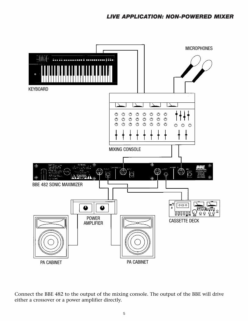
LIVE APPLICATION: NON-POWERED MIXER
5
Connect the BBE 482 to the output of the mixing console. The output of the BBE will driveeither a crossover or a power amplifier directly.
MICROPHONES
PA CABINET PA CABINET
POWER AMPLIFIER
KEYBOARD
MIXING CONSOLE
BBE 482 SONIC MAXIMIZER
CASSETTE DECK
CALIFORNIA USAMODEL 482US PATENT
NO 4,482,866AND OTHERS
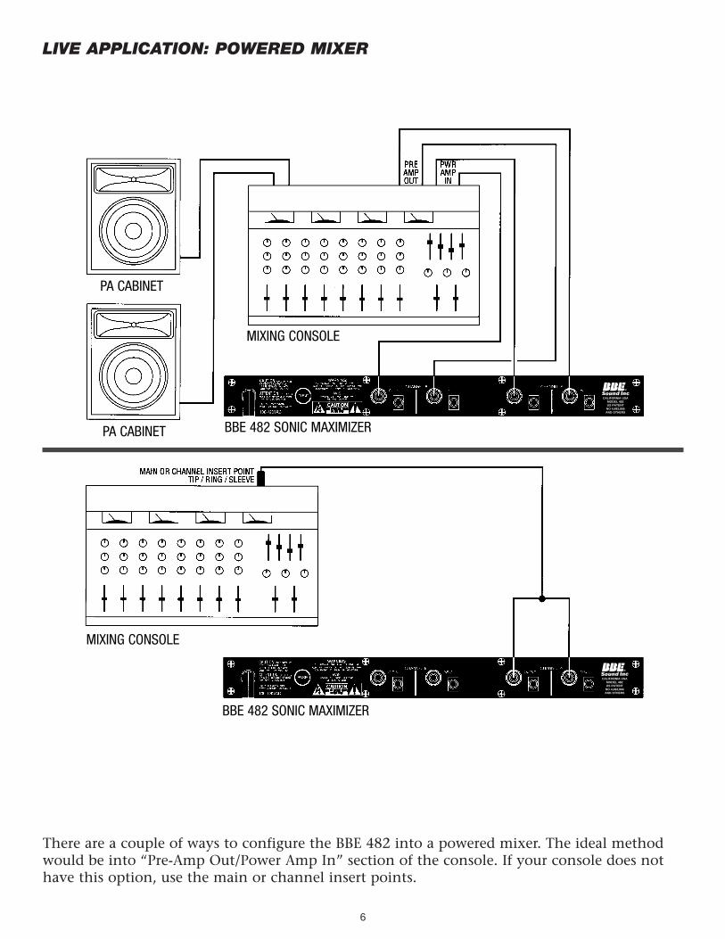
LIVE APPLICATION: POWERED MIXER
6
There are a couple of ways to configure the BBE 482 into a powered mixer. The ideal methodwould be into “Pre-Amp Out/Power Amp In” section of the console. If your console does nothave this option, use the main or channel insert points.
PA CABINET
PA CABINET
MIXING CONSOLE
MIXING CONSOLE
BBE 482 SONIC MAXIMIZER
BBE 482 SONIC MAXIMIZER
CALIFORNIA USAMODEL 482US PATENT
NO 4,482,866AND OTHERS
CALIFORNIA USAMODEL 482US PATENT
NO 4,482,866AND OTHERS
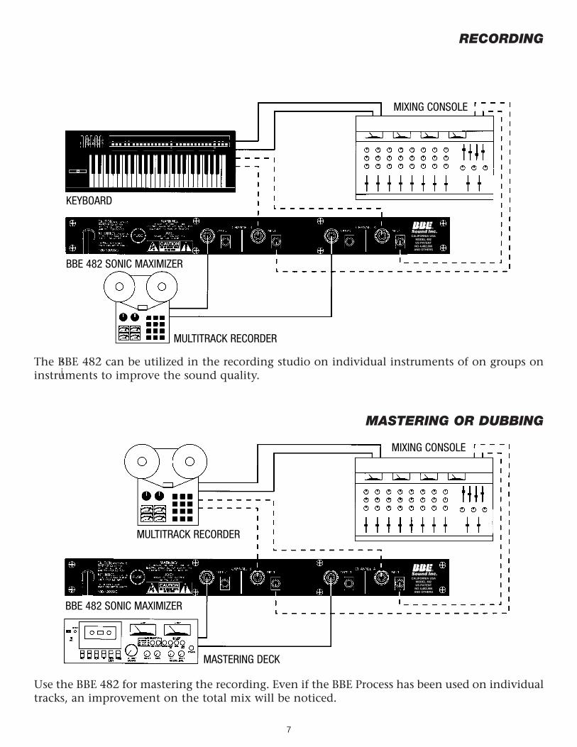
RECORDING
MASTERING OR DUBBING
7
Use the BBE 482 for mastering the recording. Even if the BBE Process has been used on individualtracks, an improvement on the total mix will be noticed.
The BBE 482 can be utilized in the recording studio on individual instruments of on groups oninstruments to improve the sound quality.
MIXING CONSOLE
MIXING CONSOLE
BBE 482 SONIC MAXIMIZER
MULTITRACK RECORDER
MULTITRACK RECORDER
MASTERING DECK
BBE 482 SONIC MAXIMIZER
KEYBOARD
CALIFORNIA USAMODEL 482US PATENT
NO 4,482,866AND OTHERS
CALIFORNIA USAMODEL 482US PATENT
NO 4,482,866AND OTHERS
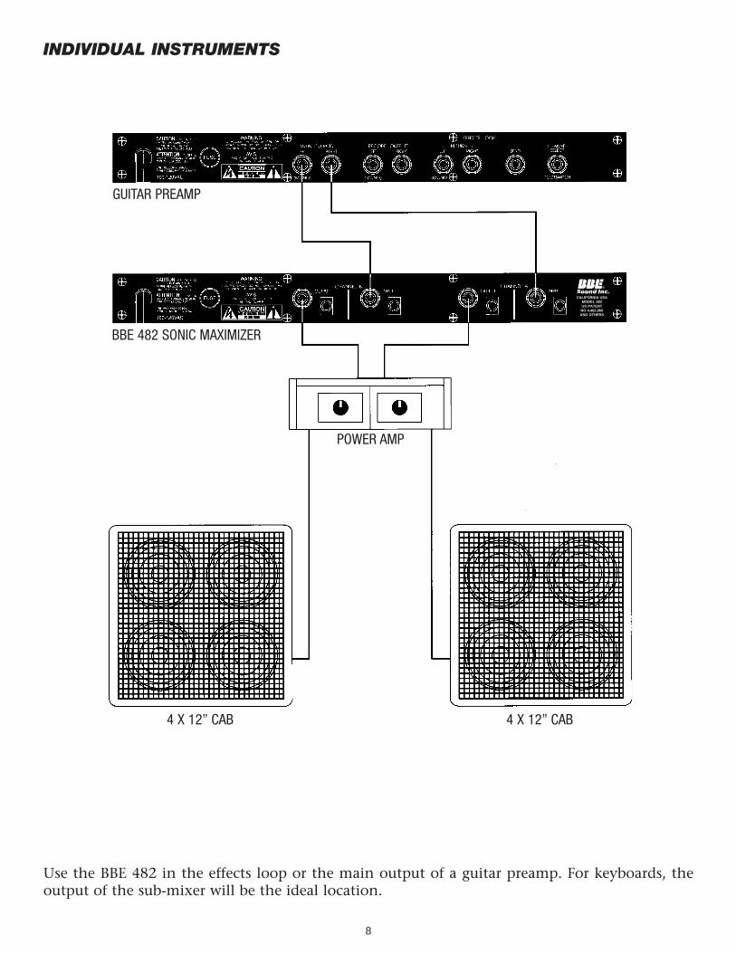
INDIVIDUAL INSTRUMENTS
8
Use the BBE 482 in the effects loop or the main output of a guitar preamp. For keyboards, theoutput of the sub-mixer will be the ideal location.
POWER AMP
4 X 12” CAB 4 X 12” CAB
BBE 482 SONIC MAXIMIZER
GUITAR PREAMP
CALIFORNIA USAMODEL 482US PATENT
NO 4,482,866AND OTHERS
9
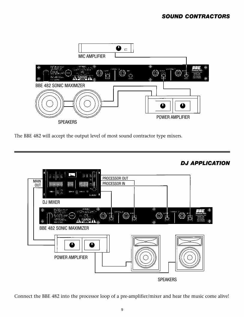
SOUND CONTRACTORS
DJ APPLICATION
Connect the BBE 482 into the processor loop of a pre-amplifier/mixer and hear the music come alive!
The BBE 482 will accept the output level of most sound contractor type mixers.
SPEAKERS
SPEAKERSPOWER AMPLIFIER
POWER AMPLIFIER
MIC AMPLIFIER
BBE 482 SONIC MAXIMIZER
BBE 482 SONIC MAXIMIZER
DJ MIXER
MAINOUT
PROCESSOR OUTPROCESSOR IN
CALIFORNIA USAMODEL 482US PATENT
NO 4,482,866AND OTHERS
CALIFORNIA USAMODEL 482US PATENT
NO 4,482,866AND OTHERS
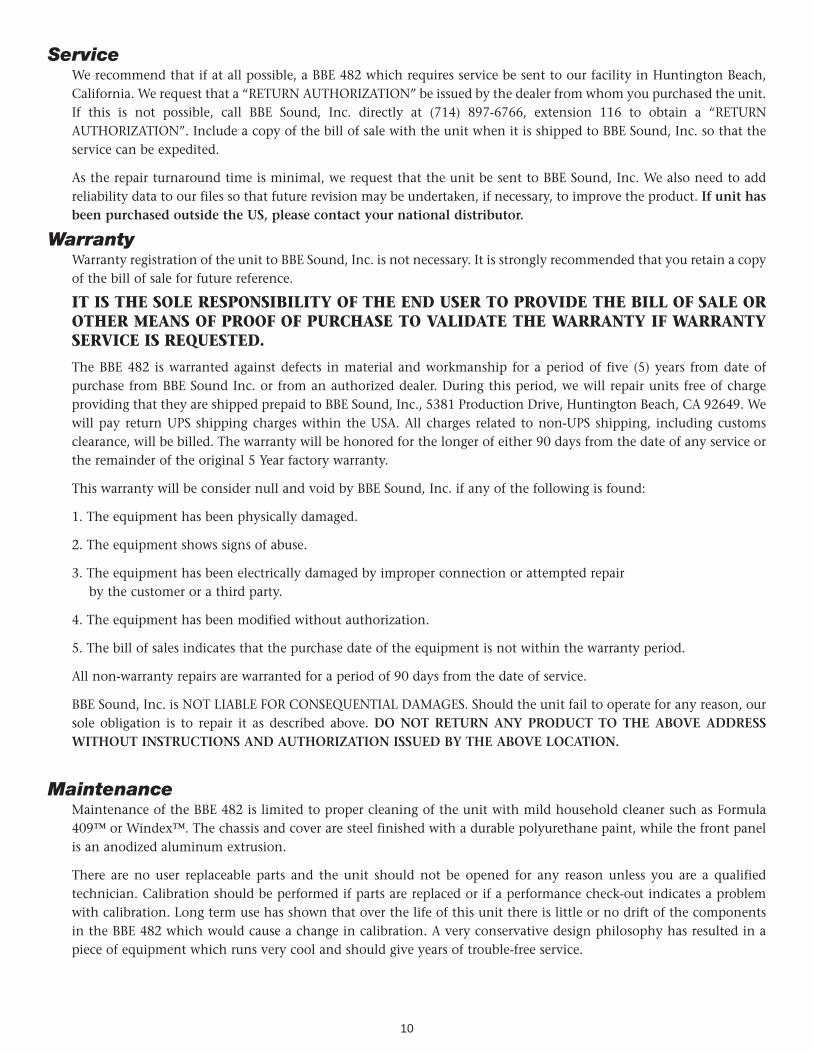
ServiceWe recommend that if at all possible, a BBE 482 which requires service be sent to our facility in Huntington Beach,California. We request that a “RETURN AUTHORIZATION” be issued by the dealer from whom you purchased the unit.If this is not possible, call BBE Sound, Inc. directly at (714) 897-6766, extension 116 to obtain a “RETURNAUTHORIZATION”. Include a copy of the bill of sale with the unit when it is shipped to BBE Sound, Inc. so that theservice can be expedited.
As the repair turnaround time is minimal, we request that the unit be sent to BBE Sound, Inc. We also need to addreliability data to our files so that future revision may be undertaken, if necessary, to improve the product. If unit hasbeen purchased outside the US, please contact your national distributor.
WarrantyWarranty registration of the unit to BBE Sound, Inc. is not necessary. It is strongly recommended that you retain a copyof the bill of sale for future reference.
IT IS THE SOLE RESPONSIBILITY OF THE END USER TO PROVIDE THE BILL OF SALE OROTHER MEANS OF PROOF OF PURCHASE TO VALIDATE THE WARRANTY IF WARRANTYSERVICE IS REQUESTED.
The BBE 482 is warranted against defects in material and workmanship for a period of five (5) years from date ofpurchase from BBE Sound Inc. or from an authorized dealer. During this period, we will repair units free of chargeproviding that they are shipped prepaid to BBE Sound, Inc., 5381 Production Drive, Huntington Beach, CA 92649. Wewill pay return UPS shipping charges within the USA. All charges related to non-UPS shipping, including customsclearance, will be billed. The warranty will be honored for the longer of either 90 days from the date of any service orthe remainder of the original 5 Year factory warranty.
This warranty will be consider null and void by BBE Sound, Inc. if any of the following is found:
1. The equipment has been physically damaged.
2. The equipment shows signs of abuse.
3. The equipment has been electrically damaged by improper connection or attempted repair by the customer or a third party.
4. The equipment has been modified without authorization.
5. The bill of sales indicates that the purchase date of the equipment is not within the warranty period.
All non-warranty repairs are warranted for a period of 90 days from the date of service.
BBE Sound, Inc. is NOT LIABLE FOR CONSEQUENTIAL DAMAGES. Should the unit fail to operate for any reason, oursole obligation is to repair it as described above. DO NOT RETURN ANY PRODUCT TO THE ABOVE ADDRESSWITHOUT INSTRUCTIONS AND AUTHORIZATION ISSUED BY THE ABOVE LOCATION.
MaintenanceMaintenance of the BBE 482 is limited to proper cleaning of the unit with mild household cleaner such as Formula409™ or Windex™. The chassis and cover are steel finished with a durable polyurethane paint, while the front panelis an anodized aluminum extrusion.
There are no user replaceable parts and the unit should not be opened for any reason unless you are a qualifiedtechnician. Calibration should be performed if parts are replaced or if a performance check-out indicates a problemwith calibration. Long term use has shown that over the life of this unit there is little or no drift of the componentsin the BBE 482 which would cause a change in calibration. A very conservative design philosophy has resulted in apiece of equipment which runs very cool and should give years of trouble-free service.
10
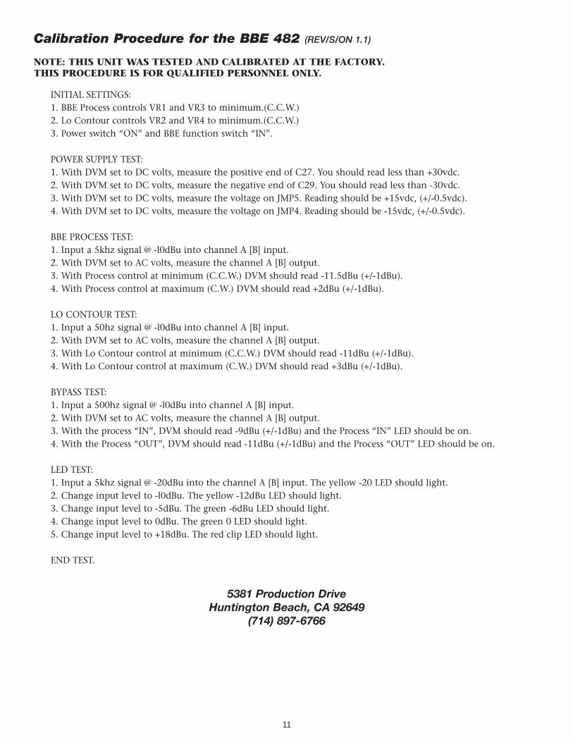
Calibration Procedure for the BBE 482 (REV/S/ON 1.1)
NOTE: THIS UNIT WAS TESTED AND CALIBRATED AT THE FACTORY. THIS PROCEDURE IS FOR QUALIFIED PERSONNEL ONLY.
INITIAL SETTINGS:1. BBE Process controls VR1 and VR3 to minimum.(C.C.W.)2. Lo Contour controls VR2 and VR4 to minimum.(C.C.W.)3. Power switch “ON” and BBE function switch “IN”.
POWER SUPPLY TEST:1. With DVM set to DC volts, measure the positive end of C27. You should read less than +30vdc.2. With DVM set to DC volts, measure the negative end of C29. You should read less than -30vdc.3. With DVM set to DC volts, measure the voltage on JMP5. Reading should be +15vdc, (+/-0.5vdc).4. With DVM set to DC volts, measure the voltage on JMP4. Reading should be -15vdc, (+/-0.5vdc).
BBE PROCESS TEST:1. Input a 5khz signal @ -l0dBu into channel A [B] input.2. With DVM set to AC volts, measure the channel A [B] output.3. With Process control at minimum (C.C.W.) DVM should read -11.5dBu (+/-1dBu).4. With Process control at maximum (C.W.) DVM should read +2dBu (+/-1dBu).
LO CONTOUR TEST:1. Input a 50hz signal @ -l0dBu into channel A [B] input.2. With DVM set to AC volts, measure the channel A [B] output.3. With Lo Contour control at minimum (C.C.W.) DVM should read -11dBu (+/-1dBu).4. With Lo Contour control at maximum (C.W.) DVM should read +3dBu (+/-1dBu).
BYPASS TEST:1. Input a 500hz signal @ -l0dBu into channel A [B] input.2. With DVM set to AC volts, measure the channel A [B] output.3. With the process “IN”, DVM should read -9dBu (+/-1dBu) and the Process “IN” LED should be on.4. With the Process “OUT”, DVM should read -11dBu (+/-1dBu) and the Process “OUT” LED should be on.
LED TEST:1. Input a 5khz signal @ -20dBu into the channel A [B] input. The yellow -20 LED should light.2. Change input level to -l0dBu. The yellow -12dBu LED should light.3. Change input level to -5dBu. The green -6dBu LED should light.4. Change input level to 0dBu. The green 0 LED should light.5. Change input level to +18dBu. The red clip LED should light.
END TEST.
5381 Production DriveHuntington Beach, CA 92649
(714) 897-6766
11
12
13
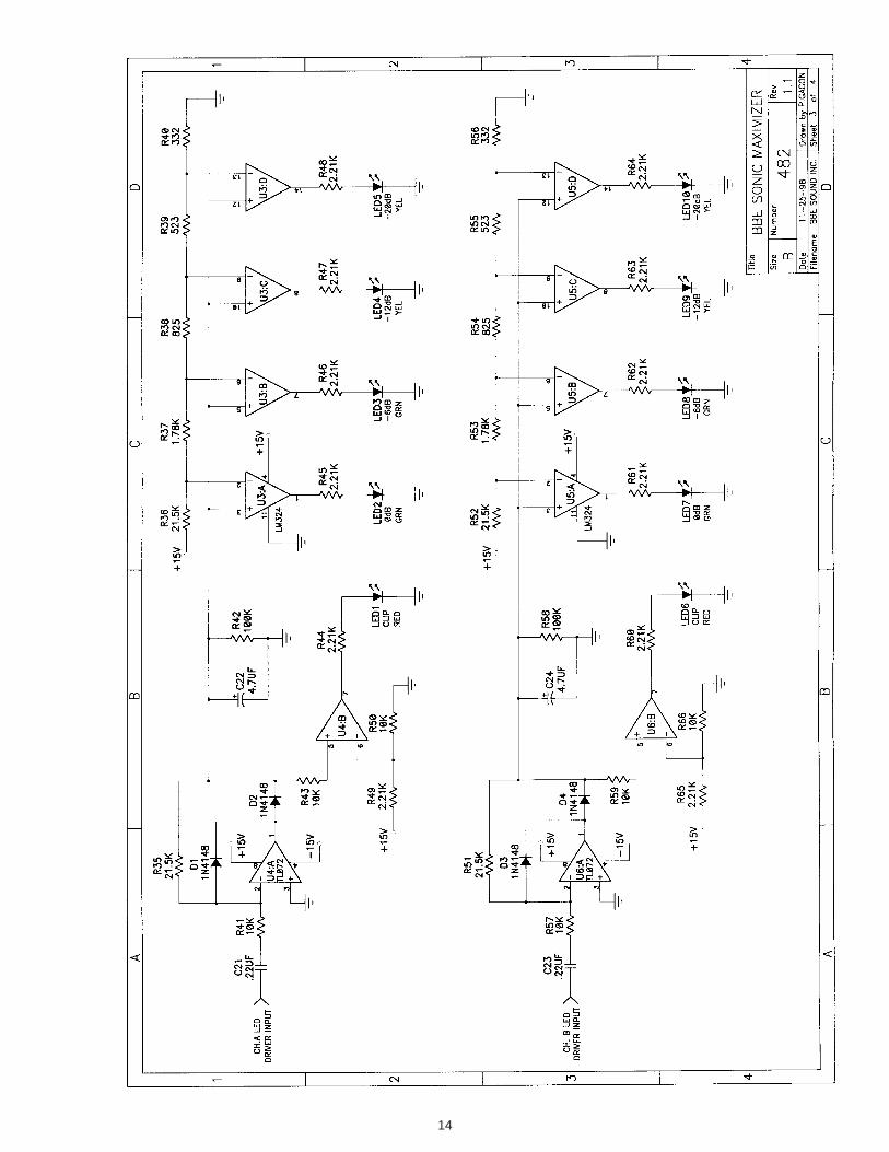
14
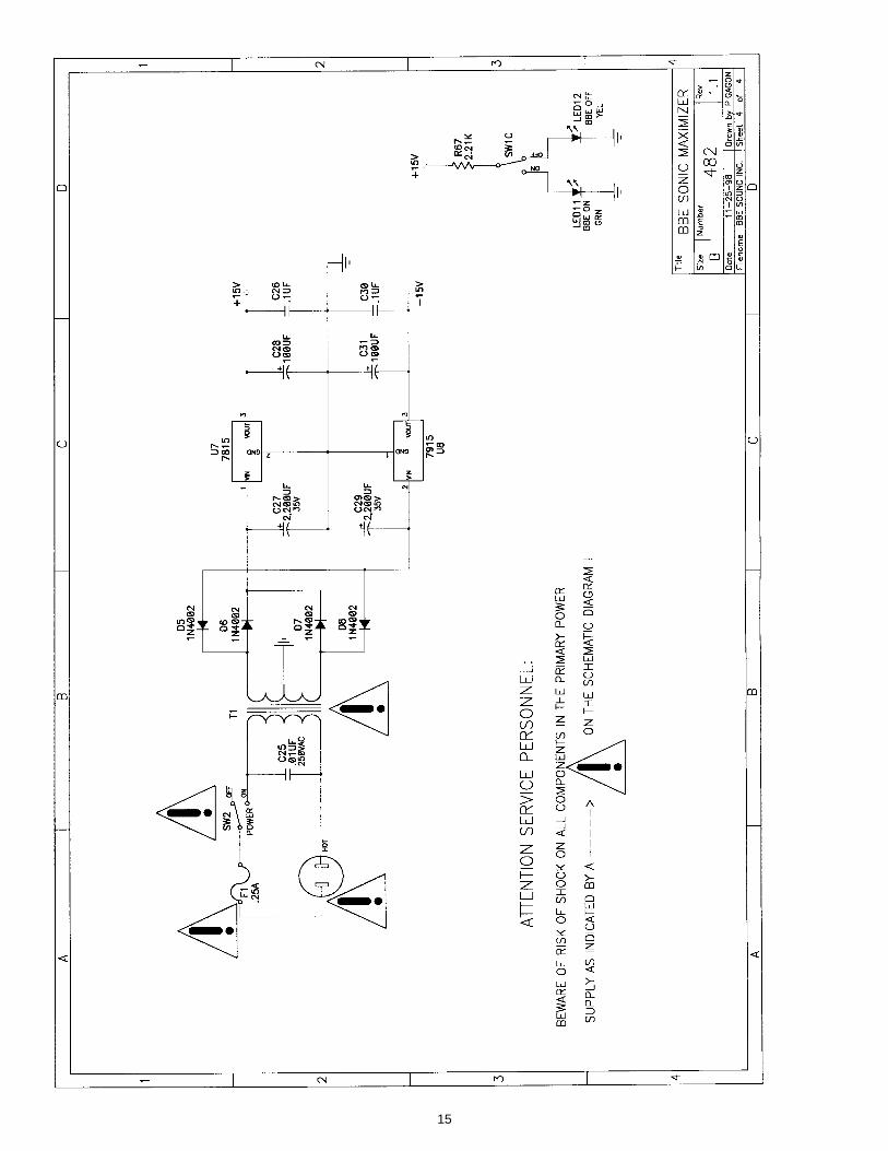
15

NOTES:
16

NOTES:
17

5381 Production DriveHuntington Beach, CA 92649
714-897-6766 • FAX 714-896-0736
www.bbesound.com
covered by U.S. Patent 4,482,866 and other U.S. and foreign patents pending.BBE is the registered trademark of BBE Sound, Inc.
• BBE •F
IVE
YE
AR
L I M I T E D
WA
RR
AN
TY
5555
rev. 1 5/99