Embed Size (px)
Citation preview
Bloomfield Hills, MI 2013-2015Work Process, Cranbrook Academy of Art
Master of Architecture
空 間 探 索Spatial Exploration
02
I am interested in how people feel about space and how to define it. Such ideas were tested and reexamined using architectural models or structures.
My studio space in Architecture Department
03
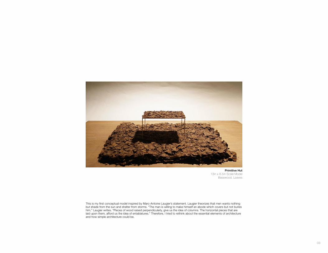
This is my first conceptual model inspired by Marc-Antoine Laugier’s statement. Laugier theorizes that men wants nothing but shade from the sun and shelter from storms. “The man is willing to make himself an abode which covers but not buries him,” Laugier writes. “Pieces of wood raised perpendicularly, give us the idea of columns. The horizontal pieces that are laid upon them, afford us the idea of entablatures.” Therefore, I tried to rethink about the essential elements of architecture and how simple architecture could be.
Primitive Hut 13in x 8.5in Scale Model
Basswood, Leaves
04
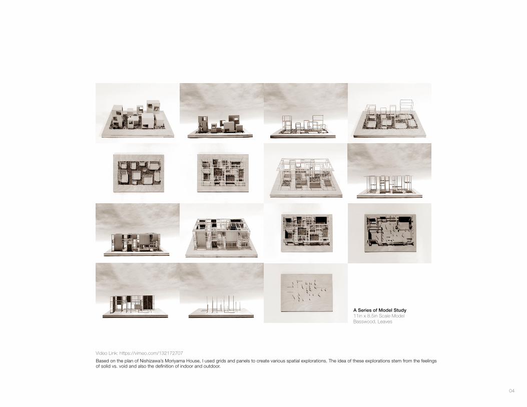
Based on the plan of Nishizawa’s Moriyama House, I used grids and panels to create various spatial explorations. The idea of these explorations stem from the feelings of solid vs. void and also the definition of indoor and outdoor.
A Series of Model Study11in x 8.5in Scale ModelBasswood, Leaves
Video Link: https://vimeo.com/132172707
05
00:4300:00 01:42 02:55 03:36
00:5000:04 02:07 03:03 03:42
00:5300:23 02:13 03:14 04:05
00:5500:30 02:15 03:22 04:24
00:5700:33 02:29 03:26 04:28
01:1400:35 02:41 03:28 04:38
00:5200:20 02:11 03:10 04:01
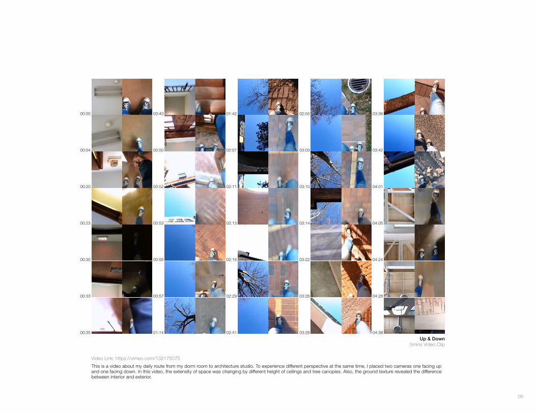
Up & Down5mins Video Clip
Video Link: https://vimeo.com/132175075
This is a video about my daily route from my dorm room to architecture studio. To experience different perspective at the same time, I placed two cameras one facing up and one facing down. In this video, the extensity of space was changing by different height of ceilings and tree canopies. Also, the ground texture revealed the difference between interior and exterior.
06
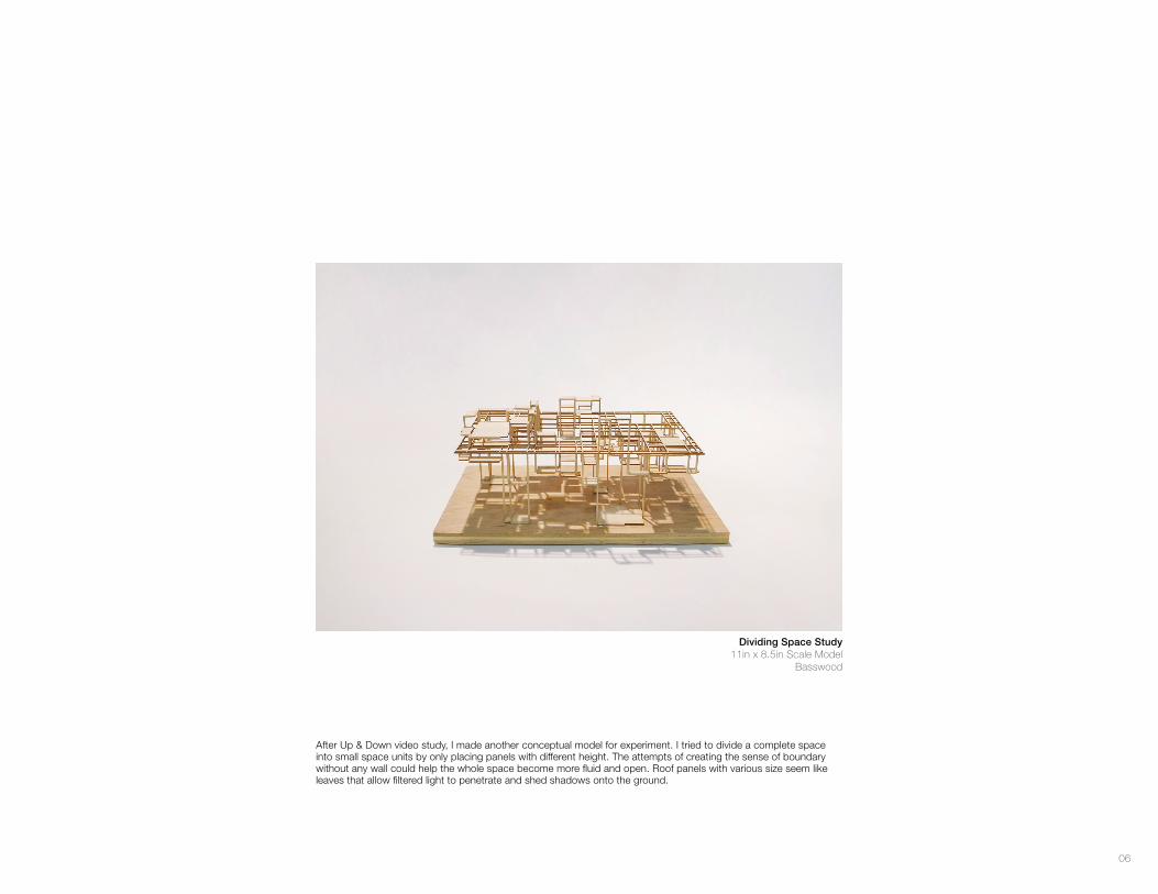
After Up & Down video study, I made another conceptual model for experiment. I tried to divide a complete space into small space units by only placing panels with different height. The attempts of creating the sense of boundary without any wall could help the whole space become more fluid and open. Roof panels with various size seem like leaves that allow filtered light to penetrate and shed shadows onto the ground.
Dividing Space Study11in x 8.5in Scale Model
Basswood
07
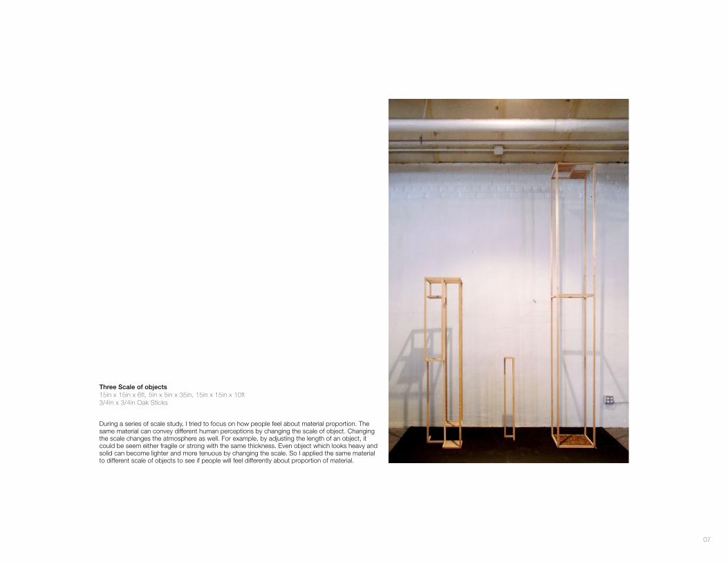
During a series of scale study, I tried to focus on how people feel about material proportion. The same material can convey different human perceptions by changing the scale of object. Changing the scale changes the atmosphere as well. For example, by adjusting the length of an object, it could be seem either fragile or strong with the same thickness. Even object which looks heavy and solid can become lighter and more tenuous by changing the scale. So I applied the same material to different scale of objects to see if people will feel differently about proportion of material.
Three Scale of objects15in x 15in x 6ft, 5in x 5in x 35in, 15in x 15in x 10ft 3/4in x 3/4in Oak Sticks
08
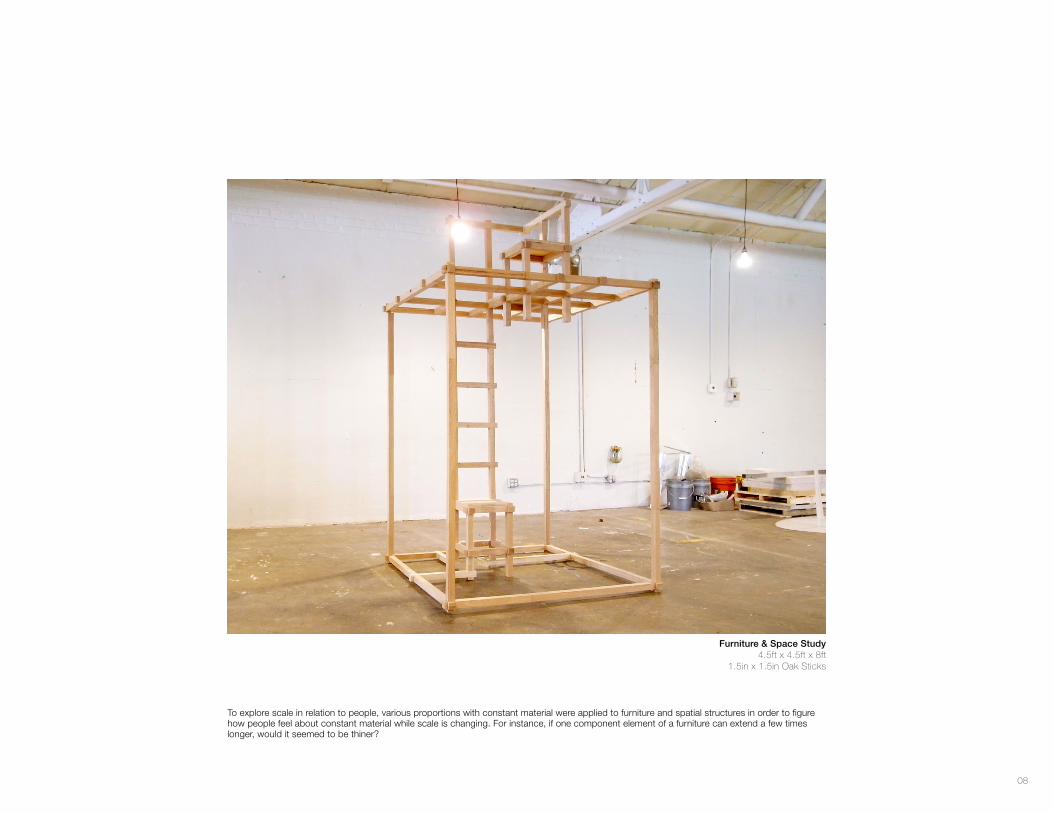
To explore scale in relation to people, various proportions with constant material were applied to furniture and spatial structures in order to figure how people feel about constant material while scale is changing. For instance, if one component element of a furniture can extend a few times longer, would it seemed to be thiner?
Furniture & Space Study4.5ft x 4.5ft x 8ft
1.5in x 1.5in Oak Sticks
09
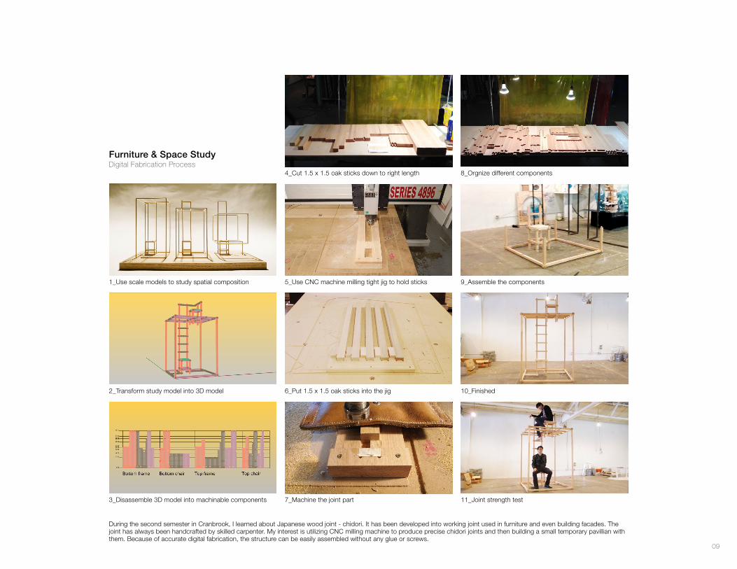
During the second semester in Cranbrook, I learned about Japanese wood joint - chidori. It has been developed into working joint used in furniture and even building facades. The joint has always been handcrafted by skilled carpenter. My interest is utilizing CNC milling machine to produce precise chidori joints and then building a small temporary pavillian with them. Because of accurate digital fabrication, the structure can be easily assembled without any glue or screws.
1_Use scale models to study spatial composition 5_Use CNC machine milling tight jig to hold sticks 9_Assemble the components
2_Transform study model into 3D model 6_Put 1.5 x 1.5 oak sticks into the jig 10_Finished
11_Joint strength test3_Disassemble 3D model into machinable components 7_Machine the joint part
4_Cut 1.5 x 1.5 oak sticks down to right length 8_Orgnize different components
Furniture & Space StudyDigital Fabrication Process
10
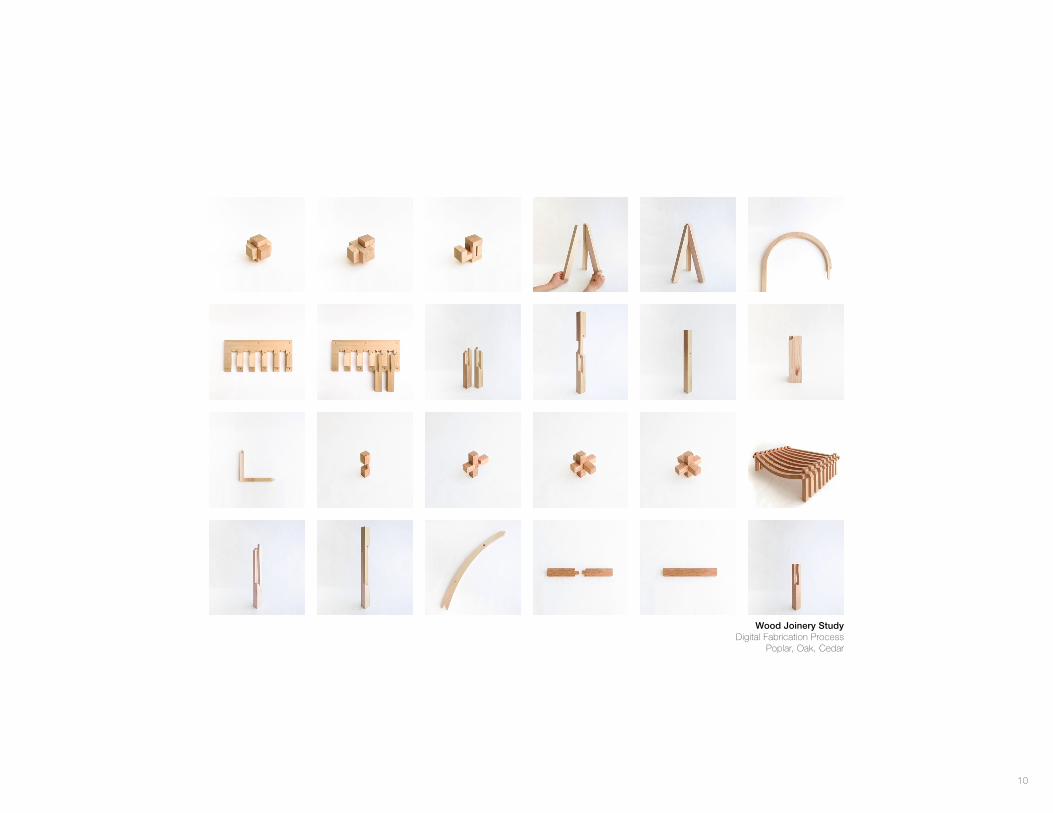
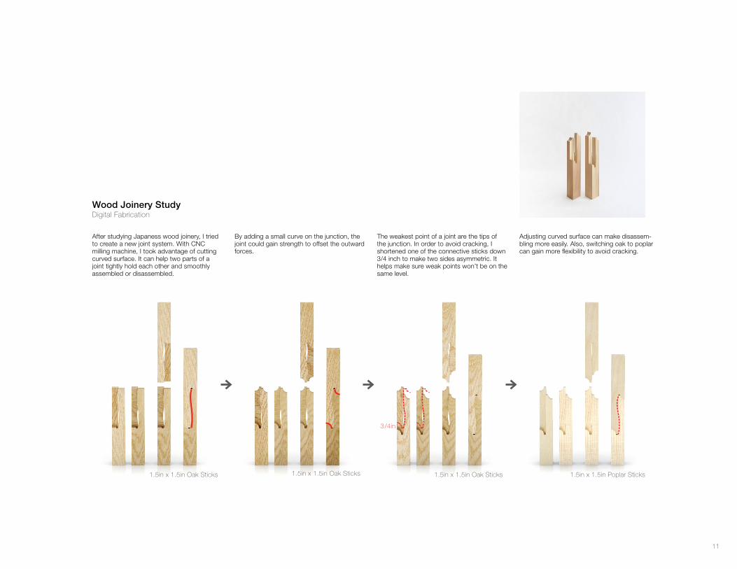
Wood Joinery StudyDigital Fabrication Process
Poplar, Oak, Cedar
11
1.5in x 1.5in Oak Sticks 1.5in x 1.5in Oak Sticks
3 /4in
1.5in x 1.5in Oak Sticks 1.5in x 1.5in Poplar Sticks
After studying Japaness wood joinery, I tried to create a new joint system. With CNC milling machine, I took advantage of cutting curved surface. It can help two parts of a joint tightly hold each other and smoothly assembled or disassembled.
By adding a small curve on the junction, the joint could gain strength to offset the outward forces.
The weakest point of a joint are the tips of the junction. In order to avoid cracking, I shortened one of the connective sticks down 3/4 inch to make two sides asymmetric. It helps make sure weak points won’t be on the same level.
Adjusting curved surface can make disassem-bling more easily. Also, switching oak to poplar can gain more flexibility to avoid cracking.
Wood Joinery StudyDigital Fabrication
12
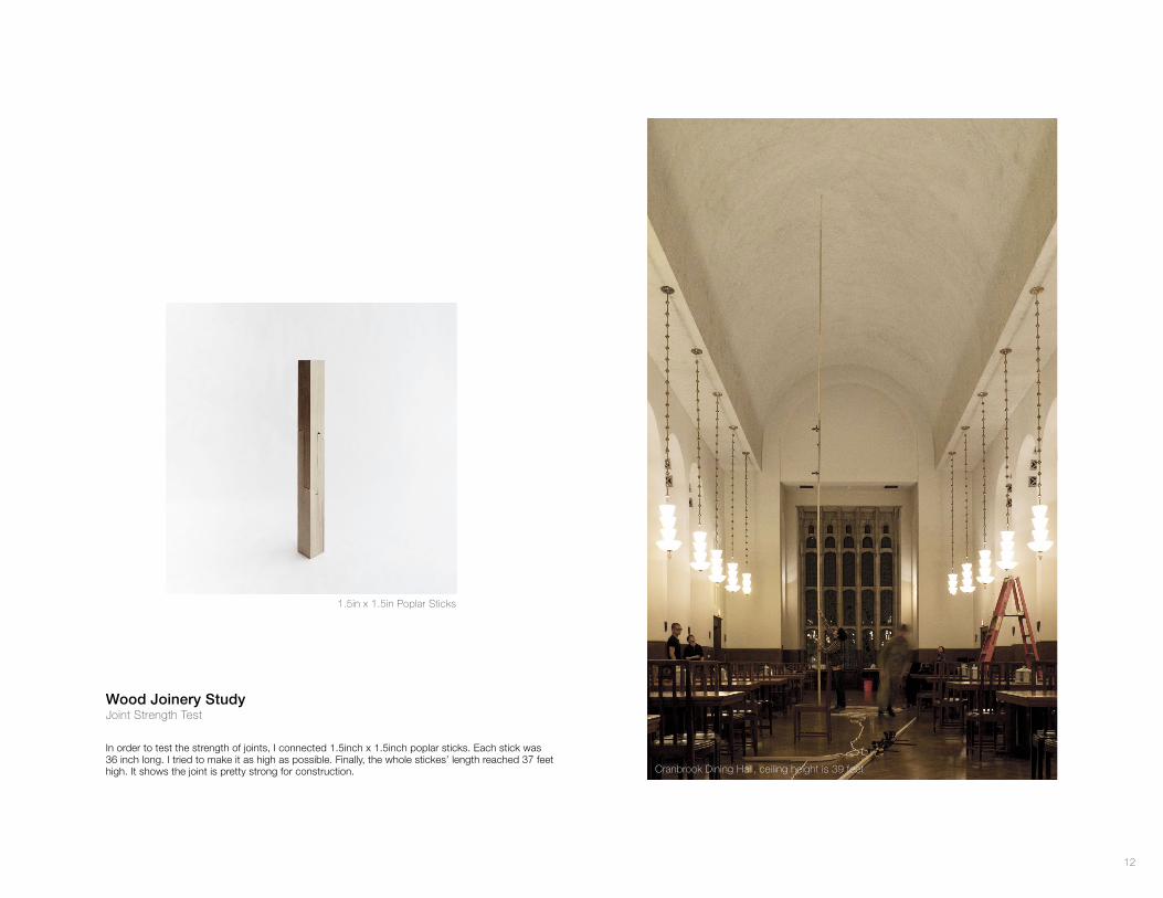
1.5in x 1.5in Poplar Sticks
Cranbrook Dining Hall, ceiling height is 39 feet
In order to test the strength of joints, I connected 1.5inch x 1.5inch poplar sticks. Each stick was 36 inch long. I tried to make it as high as possible. Finally, the whole stickes’ length reached 37 feet high. It shows the joint is pretty strong for construction.
Wood Joinery StudyJoint Strength Test
13
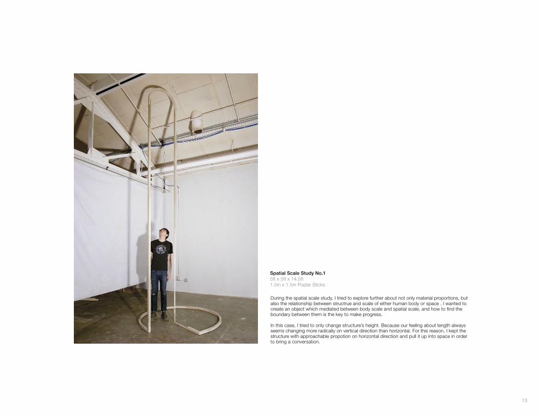
Spatial Scale Study No.15ft x 5ft x 14.5ft1.5in x 1.5in Poplar Sticks
During the spatial scale study, I tried to explore further about not only material proportions, but also the relationship between structrue and scale of either human body or space . I wanted to create an object which mediated between body scale and spatial scale, and how to find the boundary between them is the key to make progress.
In this case, I tried to only change structure’s height. Because our feeling about length always seems changing more radically on vertical direction than horizontal. For this reason, I kept the structure with approachable propotion on horizontal direction and pull it up into space in order to bring a conversation.
14
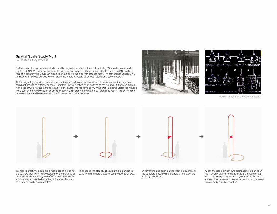
Spatial Scale Study No.1Foundation Study Process
Traditional Japanese House Foundation
Further more, the spatial scale study could be regarded as a experiment of exploring “Computer Numerically Controlled (CNC)” operational approach. Each project presents different ideas about how to use CNC milling machine transforming virtual 3D model to an actual object efficiently and precisely. The first project utilized CNC to machining curved surface which helped the whole structure to be both stable and easy to install.
At the beginning, the study was focused on the foundation cause it must be moveable so that the structure could get access to different spaces. Therefore, the foundation can’t be fixed to the ground. But how to make a high-rised structure stable and moveable at the same time? It came to my mind that traditional Japanese houses were built by erecting wooden columns on top of a flat stony foundation. So, I started to rethink the connection between pillars and base, and also the formation to provide balance.
In order to erect two pillars up, I made use of a looping shape. Two arch parts were decided for the purpose of more efficiently machining with CNC router. The whole stucture was connected with the joint system I made, so it can be easily disassembled.
To enhance the stability of structure, I expanded its base. And the circle shape keeps the feeling of loop.
By retreating one pillar making them not alignment, the structure became more stable and enable it to avoiding falls down.
Widen the gap between two pillars from 12 inch to 24 inch not only gives more stability to the structure but also provides a proper width of gateway for people to access. This movement created a relationship between human body and the structure.
15
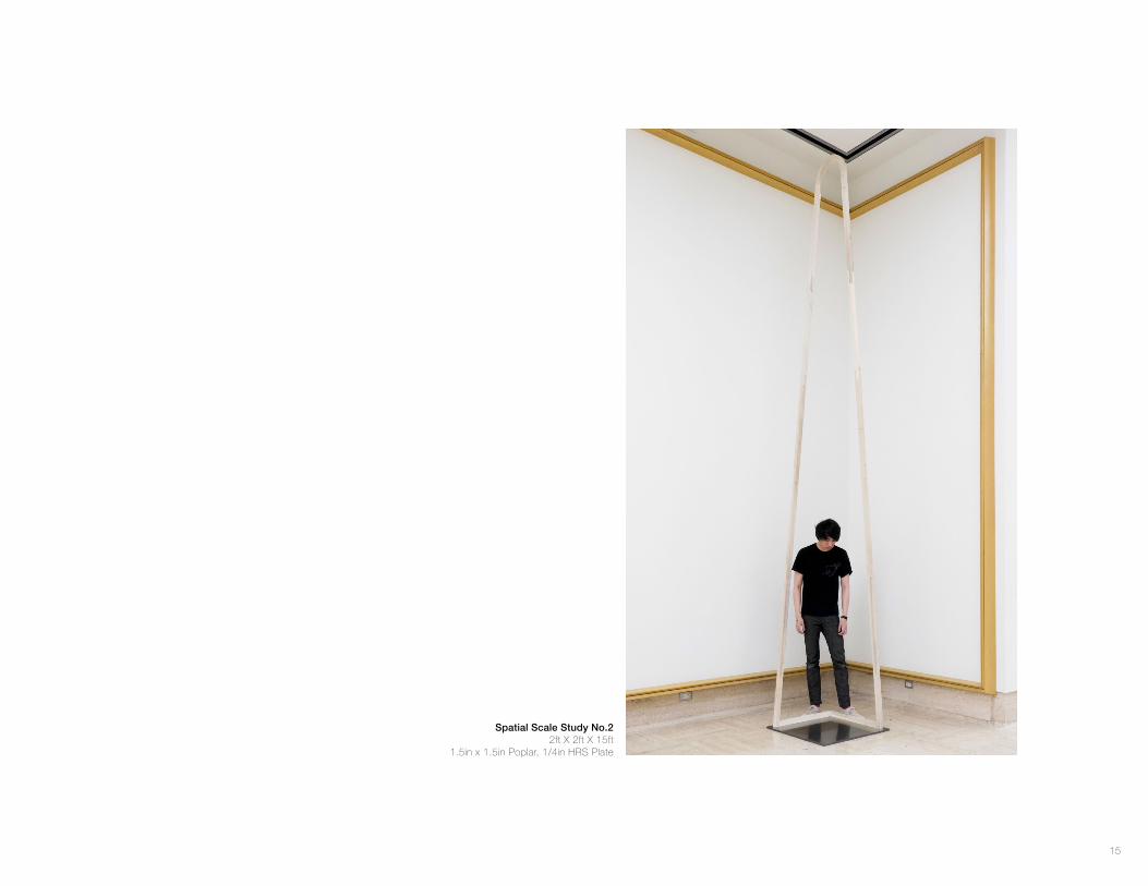
Spatial Scale Study No.22ft X 2ft X 15ft
1.5in x 1.5in Poplar, 1/4in HRS Plate
16
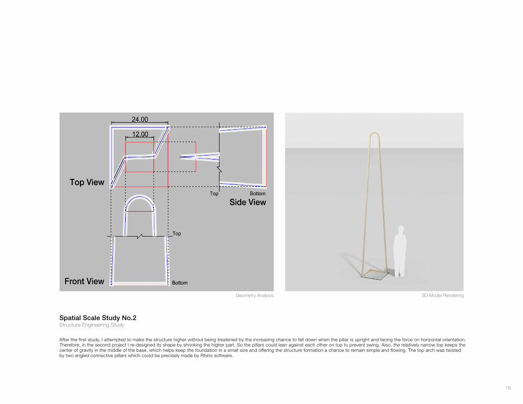
After the first study, I attempted to make the structure higher without being treatened by the increasing chance to fall down when the pillar is upright and facing the force on horizontal orientation. Therefore, in the second project I re-designed its shape by shrinking the higher part. So the pillars could lean against each other on top to prevent swing. Also, the relatively narrow top keeps the center of gravity in the middle of the base, which helps keep the foundation in a small size and offering the structure formation a chance to remain simple and flowing. The top arch was twisted by two angled connective pillars which could be precisely made by Rhino software.
3D Model RenderingGeometry Analysis
Spatial Scale Study No.2Structure Engineering Study
17
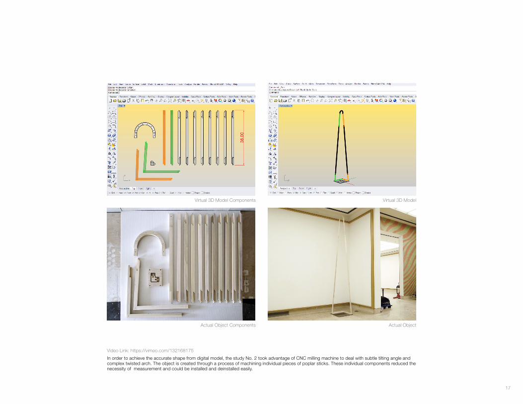
Actual ObjectActual Object Components
Virtual 3D ModelVirtual 3D Model Components
In order to achieve the accurate shape from digital model, the study No. 2 took advantage of CNC milling machine to deal with subtle tilting angle and complex twisted arch. The object is created through a process of machining individual pieces of poplar sticks. These individual components reduced the necessity of measurement and could be installed and deinstalled easily.
Video Link: https://vimeo.com/132168175
18
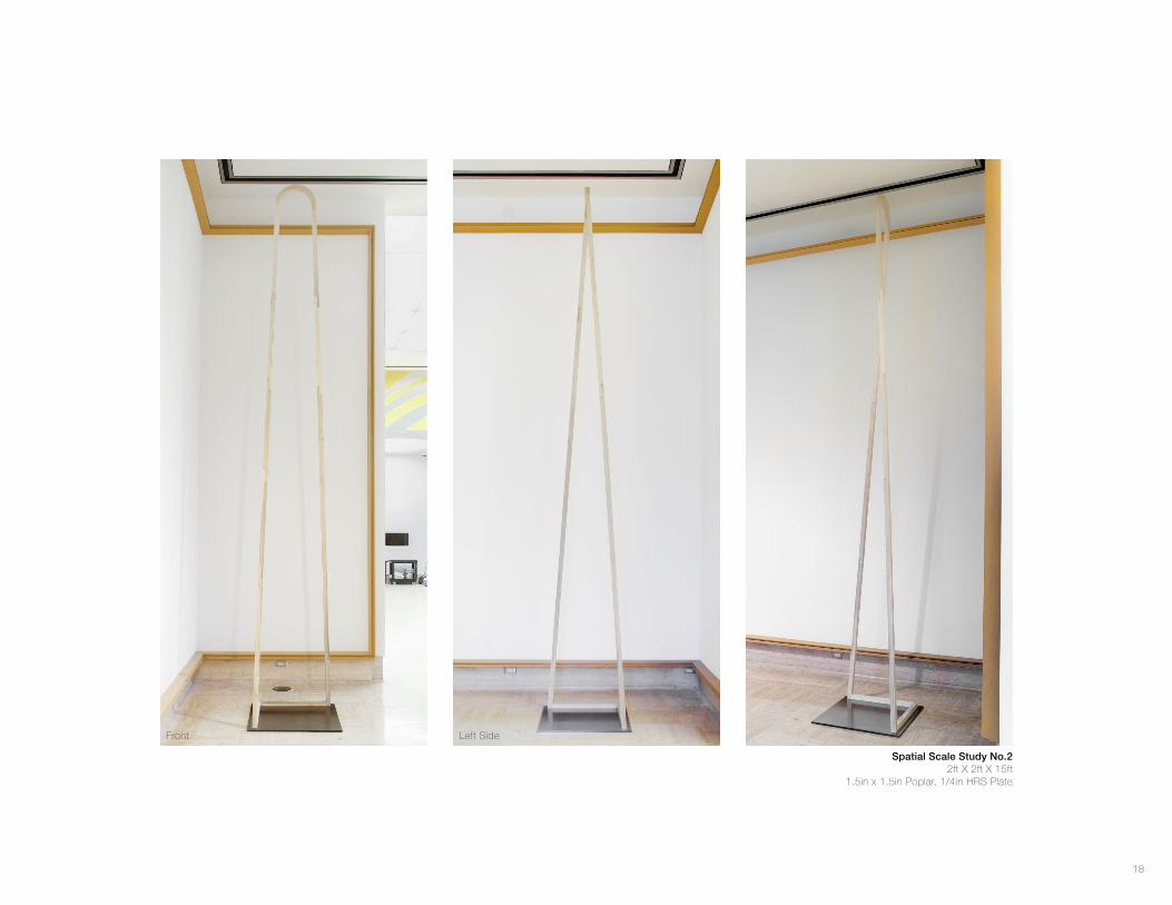
Spatial Scale Study No.22ft X 2ft X 15ft
1.5in x 1.5in Poplar, 1/4in HRS Plate
Front Left Side
19
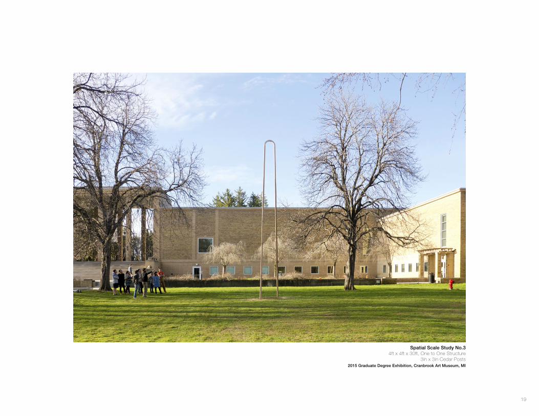
Spatial Scale Study No.34ft x 4ft x 30ft, One to One Structure
3in x 3in Cedar Posts2015 Graduate Degree Exhibition, Cranbrook Art Museum, MI
20
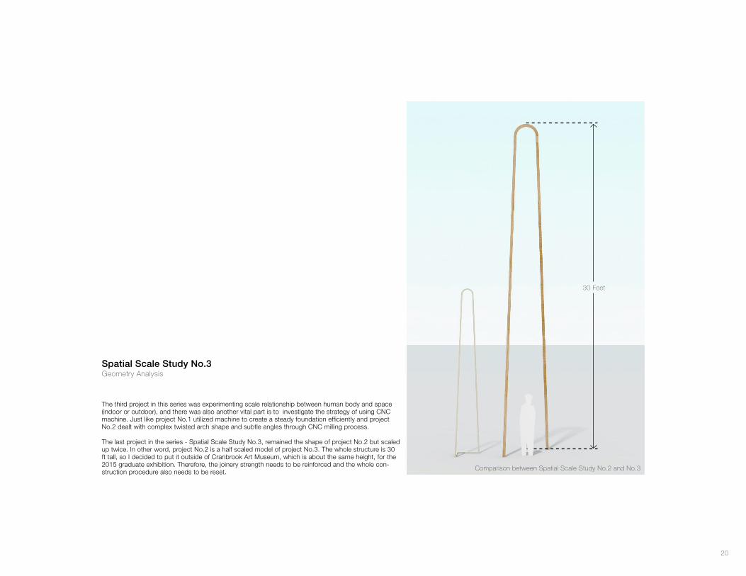
Comparison between Spatial Scale Study No.2 and No.3
30 Feet
Spatial Scale Study No.3Geometry Analysis
The third project in this series was experimenting scale relationship between human body and space (indoor or outdoor), and there was also another vital part is to investigate the strategy of using CNC machine. Just like project No.1 utilized machine to create a steady foundation efficiently and project No.2 dealt with complex twisted arch shape and subtle angles through CNC milling process.
The last project in the series - Spatial Scale Study No.3, remained the shape of project No.2 but scaled up twice. In other word, project No.2 is a half scaled model of project No.3. The whole structure is 30 ft tall, so I decided to put it outside of Cranbrook Art Museum, which is about the same height, for the 2015 graduate exhibition. Therefore, the joinery strength needs to be reinforced and the whole con-struction procedure also needs to be reset.
21
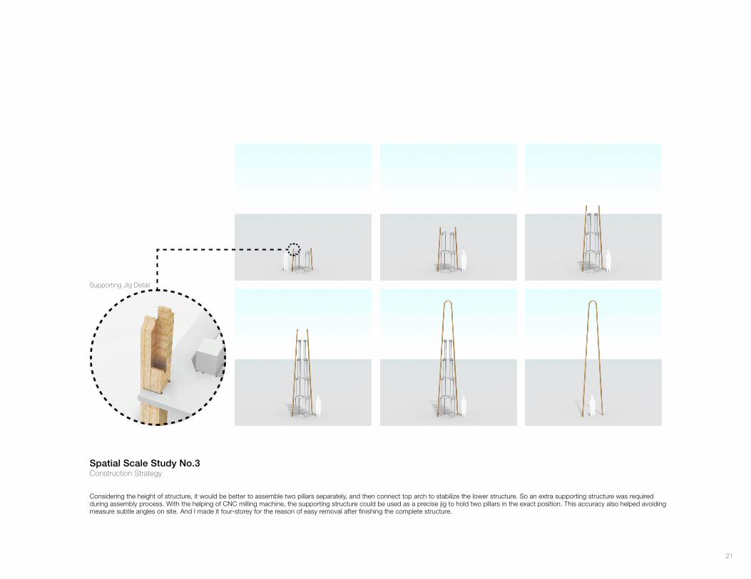
Spatial Scale Study No.3Construction Strategy
Supporting Jig Detail
Considering the height of structure, it would be better to assemble two pillars separately, and then connect top arch to stabilize the lower structure. So an extra supporting structure was required during assembly process. With the helping of CNC milling machine, the supporting structure could be used as a precise jig to hold two pillars in the exact position. This accuracy also helped avoiding measure subtle angles on site. And I made it four-storey for the reason of easy removal after finishing the complete structure.
22
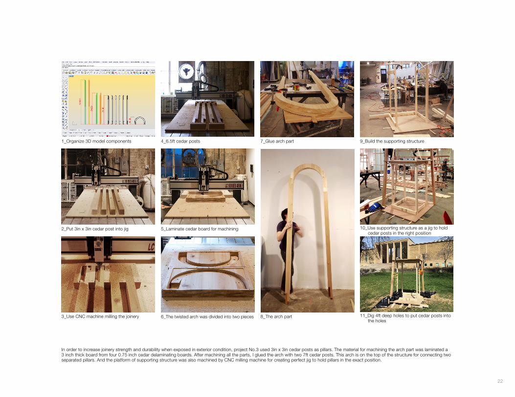
1_Organize 3D model components 7_Glue arch part4_6.5ft cedar posts 9_Build the supporting structure
10_Use supporting structure as a jig to hold cedar posts in the right position
11_Dig 4ft deep holes to put cedar posts into the holes
5_Laminate cedar board for machining
6_The twisted arch was divided into two pieces 8_The arch part
2_Put 3in x 3in cedar post into jig
3_Use CNC machine milling the joinery
In order to increase joinery strength and durability when exposed in exterior condition, project No.3 used 3in x 3in cedar posts as pillars. The material for machining the arch part was laminated a 3 inch thick board from four 0.75 inch cedar delaminating boards. After machining all the parts, I glued the arch with two 7ft cedar posts. This arch is on the top of the structure for connecting two separated pillars. And the platform of supporting structure was also machined by CNC milling machine for creating perfect jig to hold pillars in the exact position.
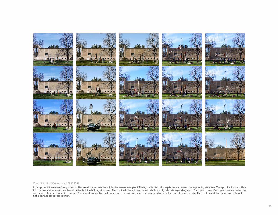
23
Video Link: https://vimeo.com/128333398
In this project, there are 4ft long of each pillar were inserted into the soil for the sake of windproof. Firstly, I drilled two 4ft deep holes and leveled the supporting structure; Then put the first two pillars into the holes, after make sure they all perfectly fit the holding structure, I filled up the holes with secure set, which is a high-density expanding foam. The top arch was lifted up and connected on the separated pillars by a boom lift machine. And after all connecting parts were done, the last step was remove supporting structure and clean up the site. The whole installation procedure only took half a day and six people to finish.
24
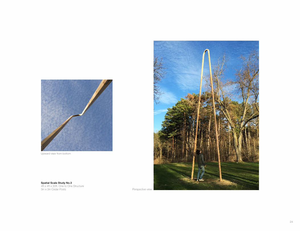
Spatial Scale Study No.34ft x 4ft x 30ft, One to One Structure3in x 3in Cedar Posts
Upward view from bottom
Perspective view
25
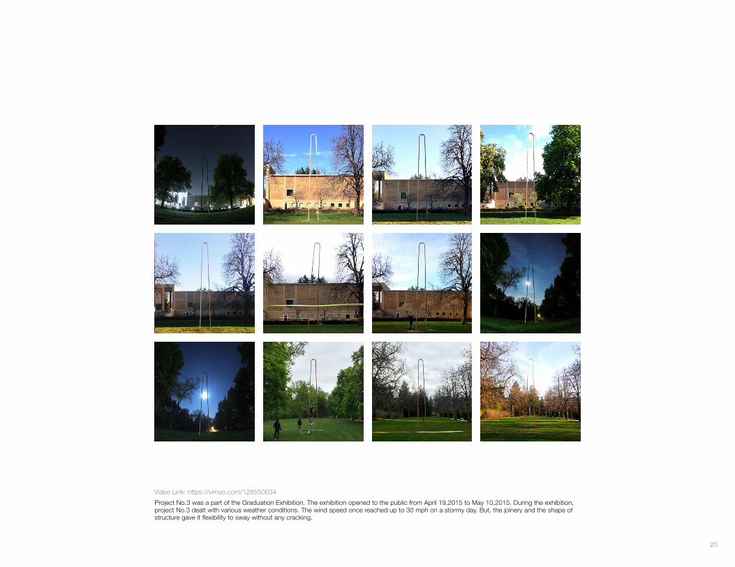
Video Link: https://vimeo.com/128550634
Project No.3 was a part of the Graduation Exhibition. The exhibition opened to the public from April 19,2015 to May 10,2015. During the exhibition, project No.3 dealt with various weather conditions. The wind speed once reached up to 30 mph on a stormy day. But, the joinery and the shape of structure gave it flexibility to sway without any cracking.
26
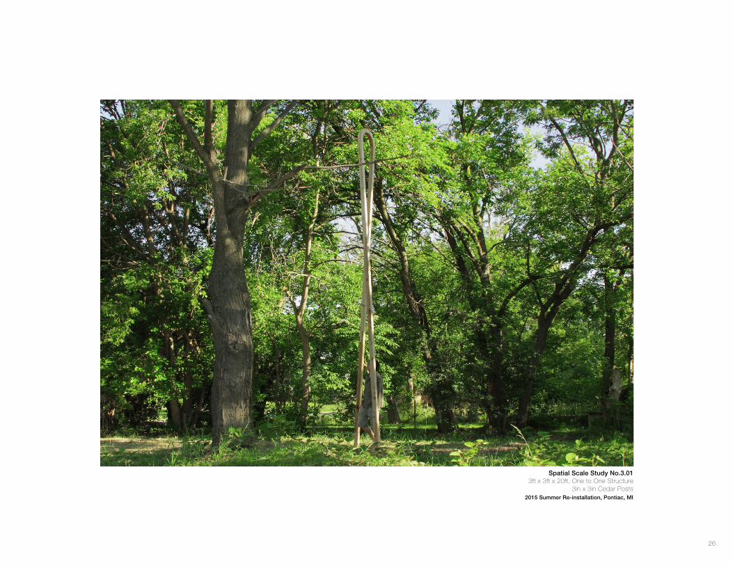
Spatial Scale Study No.3.013ft x 3ft x 20ft, One to One Structure
3in x 3in Cedar Posts2015 Summer Re-installation, Pontiac, MI