Embed Size (px)
Citation preview
Spatial and Temporal Coherence;Coherent Undulator Radiation
David Attwood
University of California, Berkeley
(http://www.coe.berkeley.edu/AST/srms)

d
Ch08_F00.ai
λθ
λ
e–
Pinhole
d
λ
λθ
lcoh = λ2/2∆λ {temporal (longitudinal) coherence}
d θ = λ/2π {spatial (transverse) coherence}
or d 2θFWHM = 0.44 λ
(8.3)
(8.5)
(8.5*)
Pcoh,λ/∆λ = 1– ƒ(K)
(8.6)
(8.9)
Pcoh = Plaser (8.11)
(λ/2π)2
(dxθx)(dyθy)
(λ/2π)2
(dxθx)(dyθy)
ωω0
eλuIη(∆λ/λ)N2
8π0dxdy
Pcoh,N = Pcen
λu
COHERENCE AT SHORT WAVELENGTHSChapter 8
Professor David AttwoodUniv. California, Berkeley

d θ
λλ
CH08_YoungsExprmt_v3.ai
Young’s Double Slit Experiment: Spatial Coherence and the Persistence of Fringes
Persistence of fringes as the source grows from a point source to finite size.
Professor David AttwoodUniv. California, Berkeley
d 2θ|FWHM λ/2
λcoh = λ2/2∆λ = Ncohλ12

Spatial and Spectral Filteringto Produce Coherent Radiation
Ch08_F08.ai
Courtesy of A. Schawlow, Stanford.Professor David AttwoodUniv. California, Berkeley

Ch08_F01.ai
Coherence, Partial Coherence, and Incoherence
θd
λ λ, ∆λ
Point source oscillator– < t <
Source of finite size,divergence, and duration
Professor David AttwoodUniv. California, Berkeley

Spatial and Temporal Coherence
Ch08_Eq1_12_F2.ai
(8.1)
(8.12)
(8.3)
(8.5)
Mutual coherence factor
Longitudinal (temporal) coherence length
Full spatial (transverse) coherence
Normalize degree of spatial coherence(complex coherence factor)
A high degree of coherence (µ → 1)implies an ability to form a high contrastinterference (fringe) pattern. A low degreeof coherence (µ → 0) implies an absenceof interference, except with great care.In general radiation is partially coherent.
Transverse (spatial)coherence
Longitudinalcoherence length
Point source,harmonic oscillator
P1
P2
P2
coh = λ2/2∆λ
P1
Professor David AttwoodUniv. California, Berkeley

Spectral Bandwidth andLongitudinal Coherence Length
Ch08_F03.ai
(8.3)
Define a coherence length coh as the distance of propagation over which radiation of spectral width ∆λ becomes 180° out of phase. For a wavelength λ propagating through N cycles
and for a wavelength λ + ∆λ, a half cycle less (N – )
Equating the two
so that
λ ∆λ
∆λ
λcoh
180 phase shift1.00
coh = Nλ
coh = (N– ) (λ + ∆λ)
N = λ/2∆λ
12
12
Professor David AttwoodUniv. California, Berkeley

• Associate spatial coherence with a spherical wavefront.
• A spherical wavefront implies a point source.
• How small is a “point source”?
Ch08_XBL 915-6740A.ai
From Heisenberg’s Uncertainty
Principle (∆x · ∆p ≥ ), the smallest
source size “d” you can resolve, with
wavelength λ and half angle θ, is
d · θ =λ
2π
d
λ
θ
2
A Practical Interpretationof Spatial Coherence
Professor David AttwoodUniv. California, Berkeley

Ch08_XBL883-8849_modf.ai
Partially Coherent Radiation ApproachesUncertainty Principle Limits
∆x ∆p ≥ /2
quantities1e
∆x k∆θ ≥ 1/2
∆x ∆k ≥ /2
2∆x ∆θ ≥ λ/2π
Standard deviations of Gaussian distributed functions(Tipler, 1978, pp. 174-189)
Spherical wavefronts occurin the limiting case
or(d 2θ)FWHM λ/2 FWHM quantities
Note: ∆p = ∆k ∆k = k∆θ
d = 2∆x
(spatially coherent)
d θ = λ/2π
θ
∆k∆θk
(8.4)
Professor David AttwoodUniv. California, Berkeley

Ch08_F05.ai
Propagation of a Gaussian Beam
r0
Waist
λ
z Gaussian intensitydistribution, sphericallypropagating wave
r(z) θ
In
with waist diameter d = 2r0, we have TEM00 radiation with d θ = λ/2π
(Siegman, Lasers)
Professor David AttwoodUniv. California, Berkeley
Ch08_Heisenberg.aiProfessor David AttwoodUniv. California, Berkeley

Spatially Coherent Undulator Radiation
! = 11.2 nm ! = 13.4 nm
1 !mD pinhole
25 mm wide CCD
at 410 mm
Ch08_Coh_SXR_Sci .PPT
Professor David Attwood
Univ. California, Berkeley
Courtesy of Patrick Naulleau, LBNL.
Ch08_SpatialFiltrng.ai
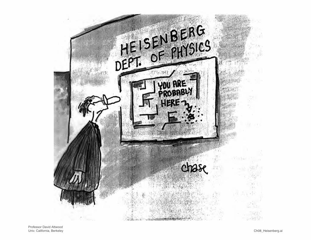
Spatial Filtering of Undulator Radiation
Undulator central radiation cone ( = N ; θ = ):
With spatial filtering (a pinhole and an angular aperture):
(5.41a)
(8.6)
(8.9)
With eq.(5.28), . Convert to photon
energies where for θ = 0, , and where
corresponds to K = 0. For small electron beamdiverence, σ′ << θcen, the spatially coherent power is
λ∆λ
1γ* N
≤ 1 ≤ 1
2 2x,y
Professor David AttwoodUniv. California, Berkeley

500 100 150 200 250 300 350 400 450
5
0
10
15
20
25
30
35
Photon energy (eV)
Tuningcurve
Coh
eren
t pow
er (
mW
)
λ∆λ = N
Pcoh = · Pcen
coh = Nλ/2
(λ/2π)2
(dxθx)(dyθy)
Spatially Filtered Undulator Radiation
Ch08_F09.ai
(8.6)
(8.9)
Using a pinhole-aperture spatial filter, passing only radiation that satisfies d θ = λ/2π
for dx = 2σx, dy = 2σy, θTx → θx, θTy → θy,and σ′2 << θcen.2
Photon energy (eV)
Pce
n (W
)
Tuningcurve
λ∆λ = N
Pcen = ·πeγ 2I0λu
K2f(K)
(1 + K2/2)2
λu = 8 cmN = 551.9 GeV0.4 ampn = 1(only)
0 100 200 300 4000
0.50
1.00
1.50
2.00Undulatorradiation
d
Spatialfilter
Pinhole
N periods
1 γ∗1
Nγ∗
1
Nγ∗
θcen =
θcen = ; = N; γ* = γ/ 1 + K2/2
λ = (1 + + γ2θ2)λu
2γ2
λ∆λ cen
θ
Angularaperture
K2
2
e–
λu
Professor David AttwoodUniv. California, Berkeley

Ch08_SpatialSpectral.ai
Spatial and Spectral Filtering of Undulater Radiation
In addition to the pinhole – angular aperture for spatialfiltering and spatial coherence, add a monochromator for narrowed bandwidth and increased temporal coherence:
which for σ′ << θcen (the undulator condition) gives thespatially and temporally coherent power ( ; )
which we note scales as N2.
(8.10a)
(8.10c)
2 2x,y
Professor David AttwoodUniv. California, Berkeley

Spatially and Spectrally FilteredUndulator Radiation
Ch08_F11_Mar08.ai
(8.10a)
(8.10c)
• Pinhole filtering for full spatial coherence• Monochromator for spectral filtering to λ/∆λ > N
M1planemirror
M2spherical
mirror
Water-cooledbeam definingapertures
8.0 cm periodundulator
EUVinterferometer
166°
Variedline-
spacegrating
Exitslit
166°
M6bendable
EntrancepinholeM5
planeM4
bendable
M3retractable
planemirror
M0retract-
ableplanemirror
EUV/soft x-rayphotoemission
microscope
8.0 cm period, N = 551.9 GeV, 400 mAd θ = λ/2πcoh = 103λ/2η = 10%
Professor David AttwoodUniv. California, Berkeley
0
100
200
300
102 103
Photon Energy (eV)
Pco
h, λ
/∆λ
(µW
)
n = 3λ
∆λ= 103
λ∆λ
= 103

Ch08_CohOptBLwGraf_Feb07.ai
Tuningcurves
8.0 cm period, N = 551.9 GeV, 400 mAd θ = λ/2πcoh = 1000 λ/2ηeuv = 10%, ηsxr = 10%
Coherent Power with a Monochromator
M2spherical2 mirror
Water-cooledbeam definingapertures
8.0 cm periodundulator
Variedline-space
grating
Exitslit172°
M4bendable2 mirror
M3bendable2 mirror
M0retractable
plane2 mirror
Entrancepinhole
CoherentSoft X-ray
End Station
K-Bfocus
system
Coherent Soft X-Ray Beamline: Use of a Higher Harmonic (n = 3) to Access Shorter Wavelengths
0
100
200
300
102 103
Photon Energy (eV)
Pco
h, λ
/∆λ
(µW
)
n = 1
n = 3
λ∆λ
= 103
Professor David AttwoodUniv. California, Berkeley

Coherent Power at the ALS
Ch08_U8_Feb07.ai
1.9 GeV, 400 mAλu = 80 mm, N = 550.5 ≤ K ≤ 4.0σx = 260 µm, σx′ = 23 µrσy = 16 µm, σy′ = 3.9 µr
0 200 400 600 800 10000
0.5
1.0
1.5
0
10
20
30
40
50
0
100
200
300
102 103102 103
Photon Energy (eV)
Photon Energy (eV)
Photon Energy (eV)
Pco
h, N
(m
W)
Pco
h, λ
/∆λ
(µW
)
Pce
n (W
)
U8
n = 1
n = 3
n = 1
n = 3
n = 1
n = 3
λ∆λ
= 55
λ∆λ = 55
λ∆λ = 165
λ∆λ
= 103
λ∆λ
= 103
ηeuv = 10%ηsxr = 10%
Professor David AttwoodUniv. California, Berkeley

Coherent Power at the ALS
Ch08_U5_Feb07.ai
1.9 GeV, 400 mAλu = 50 mm, N = 890.5 ≤ K ≤ 4.0σx = 260 µm, σx′ = 23 µrσy = 16 µm, σy′ = 3.9 µrη = 10%
U5
0 500
n = 1
n = 3
n = 1
n = 3
n = 1
n = 3
1000 1500 20000
0.5
1.0
1.5
2.0
2.5
0
10
20
30
40
50
0
100
200
300
400
102 103102 103
Photon Energy (eV)Photon Energy (eV)
Photon Energy (eV)
Pco
h, N
(m
W)
Pco
h, λ
/∆λ
(µW
)
Pce
n (W
)
λ∆λ
= 89 λ∆λ
= 103
Professor David AttwoodUniv. California, Berkeley

Ch08_ALS_U5epu_Feb07.ai
1.9 GeV, 400 mAλu = 50 mm, N = 270.5 ≤ K ≤ 4.0σx = 260 µm, σx′ = 23 µrσy = 16 µm, σy′ = 3.9 µrθcen = 61µr @ K = 0.87 (500 eV)
U5 EPU
0 500
n = 1
n = 3
n = 1
n = 3
n = 1
η = 1.3%
n = 3
1000 1500 20000
0.5
1.0
1.5
2.0
2.5
0
5
10
15
20
0
2
4
6
102 103102 103
Photon Energy (eV)Photon Energy (eV)
Photon Energy (eV)
Pco
h, N
(m
W)
Pco
h, λ
/∆λ
(µW
)
Pce
n (W
)
λ∆λ
= 27λ
∆λ = 103
Professor David AttwoodUniv. California, Berkeley
Coherent Power for an EPU at the ALS

Coherent Power Predictedwith SPEAR 3 at SSRL
Ch08_SPEAR3_SSRL_Feb07.ai
3.0 GeV, 500 mAλu = 3.3 cm, N = 1050 ≤ K ≤ 2.2σx = 436 µm, σx′ = 43 µradσy = 30 µm, σy′ = 6.3 µradθcen = 17 µrad @ K = 1η = 10%
Photon Energy (eV)
n = 1
n = 3λ∆λ
= 103
Photon Energy (eV)
Photon Energy (keV)
n = 1
n = 3λ
∆λ= 105
0 2 4 6 8
104103104103
Pco
h, N
(m
W)
Pco
h, λ
/∆λ
(µW
)
Pce
n (W
)
15
10
5
0
0
5
10
n = 1
n = 3
0
50
100
Professor David AttwoodUniv. California, Berkeley

Coherent Power at the Australian Synchrotron
CohPwr_AustralSynch_Feb07.ai
Photon Energy (eV)
n = 1
n = 3λ
∆λ= 103
Photon Energy (eV)
Photon Energy (eV)
n = 1
n = 3
λ∆λ
= 80
λ∆λ
= 80
λ∆λ= 240
0 2,000 4,000 6,000 8,000 10,000
104103104103
Pco
h, N
(m
W)
Pco
h, λ
/∆λ
(µW
)
Pce
n (W
)
8
6
2
0
0
2
4
6
n = 1
n = 3
4
0
10
20
30
40
50
3.0 GeV, 200 mAλu = 22 mm, N = 800 ≤ K ≤ 1.8σx = 320 µm, σx′ = 34 µradσy = 16 µm, σy′ = 6 µradθcen = 23 µrad @ K = 1η = 10%
Professor David AttwoodUniv. California, Berkeley

Coherent Power at the UK’s Diamond Synchrotron Facility
CohPwr_DiamondUK_Feb07.ai
3.0 GeV, 300 mAλu = 2.4 cm, N = 820 ≤ K ≤ 1.4σx = 123 µm, σx′ = 24 µrσy = 6.4 µm, σy′ = 4.2 µrθcen = 23 µr @ K = 1η = 10%1000 5000 900070003000
103 1040
200
300
100
400
500
600
Photon Energy (eV)
Pco
h, λ
/∆λ
(µW
)
Pce
n (W
)
n = 1
n = 3
n = 3
n = 1
n = 3
λ∆λ
= 103
0
2
4
8
6
10
0
10
20
30
40
50
60
103 104
Photon Energy (eV)
Photon Energy (eV)
Pco
h, N
(m
W) n = 1
λ∆λ
= 82
Courtesy of Brian Kennedy (King’s College London),Susan Smith (Daresbury), and Yanwei Liu (LBNL)
Professor David AttwoodUniv. California, Berkeley

Ch08_APS_Feb07.ai
7.00 GeV, 100 mAλu = 33 mm, N = 720.5 ≤ K ≤ 3.0σx = 320 µm, σx′ = 23 µrσy = 50 µm, σy′ = 7 µrη = 10%
0 10 20 30 400
5
10
15
0
0.2
0.4
0.6
0.8
0
2
4
6
104103 105 103 104 105
Photon Energy (eV)Photon Energy (eV)
Photon Energy (eV)
Pco
h, N
(m
W)
Pco
h, λ
/∆λ
(µW
)
Pce
n (W
)
APS
n = 1
n = 3
n = 1
n = 1
n = 3
n = 3
λ∆λ
= 72 λ∆λ
= 103
Coherent Power at the APS
Professor David AttwoodUniv. California, Berkeley

Ch08_SPring8_Feb07.ai
8 GeV, 100 mAλu = 32 mm, N = 1400 ≤ K ≤ 2.46σx = 393 µm, σx′ = 15.7 µrσy = 4.98 µm, σy′ = 1.24 µrη = 10%
n = 1
n = 3
n = 1
n = 3
n = 1
n = 3
λ∆λ
= 103λ∆λ
= 140
0 10 20 30 40 50 600
5
10
15
20
0
5
10
15
20
0
100
200
300
Photon Energy (eV)
Photon Energy (keV)
103 104 105
Photon Energy (eV)103 104 105
Pco
h, N
(m
W)
Pco
h, λ
/∆λ
(µW
)
Pce
n (W
)Coherent Power at SPring-8
Professor David AttwoodUniv. California, Berkeley

Spatially Coherent Undulator Radiation
! = 11.2 nm ! = 13.4 nm
1 !mD pinhole
25 mm wide CCD
at 410 mm
Ch08_Coh_SXR_Sci .PPT
Professor David Attwood
Univ. California, Berkeley
Courtesy of Patrick Naulleau, LBNL.

Undulator Beamline forHigh Spatial Coherence Measurements
BeamlineAperture
GratingUndulator
C. Chang
e–
CCD
Twopinholemask
0 0.2 0.4 0.6
Inte
nsity
Position
13.4 nm420 nmD
5 m sep
0.8 10
0.5
1
Ch08_CohSXRsci.aiProfessor David AttwoodUniv. California, Berkeley

Ch08_CohSXRsciChang.ppt
Professor David Attwood
Univ. California, Berkeley
Courtesy of Chang Chang, UC Berkeley and LBNL.
Spatial Coherence Measurements of Undulator
Radiation Using the Classic 2-Pinhole Technique
! = 13.4 nm, 450 nm diameter pinholes, 1024 x 1024 EUV/CCD at 26 cm ALS, 1.9 GeV, !u = 8 cm, N = 55

Ch08_CohSXRsciChang.ppt
Professor David Attwood
Univ. California, Berkeley
Courtesy of Chang Chang, UC Berkeley and LBNL.
Spatial Coherence Measurements
in the Vertical Plane
! = 13.4 nm, 450 nm diameter pinholes, 1024 x 1024 EUV/CCD at 26 cm ALS, 1.9 GeV, !u = 8 cm, N = 55

Interferogram
Coherent Undulator Radiation is Used for Interferometric
Testing of Multilayer Coated Optics for EUV Lithography
13.4 nm
Wavefront! = 0.52 nm rms = "euv /26
Null test interferogram
1.39 nm
–2.82 nm
Reference wavefront! = 0.044 nm rms = "euv /300
0.25 nm
–0.25 nm
Courtesy of K. Goldberg, P. Naulleau, J. Bokor, et al., LBNL.
Ch08_At_WaveEUV.pptProfessor David Attwood
Univ. California, Berkeley

Professor David Attwood
Univ. California Berkeley Ch08_ETS_optics.ppt
EUV Interferometry of Projection Optics
Fromundulatorbeamline
Turning mirror
Grating beam splitter And phase shifter
EUV CCD
K-B pre-focusing mirrors
PlanarBearingstage
Image stagepinhole array
Object stagepinhole array
Spatially coherent EUV radiation
Courtesy of K. Goldberg, P. Naulleau and P. Batson (LBNL) and J. Bokor (UCB/LBL).

METinterferometry.pptProfessor David Attwood
Univ. California, Berkeley
A 0.30 NA Micro-Exposure Tool (MET) for TestingEUV Resist Patterns to 12 nm Feature Size
Mask
Illumination
Secondary
Wafer
Primary
Fold Flat
Bipods
Bipod
Button
(Courtesy of J. Taylor, LLNL)
MET
NA = 0.30
13.4 nm
5X
200 X 600 µm field

METinterferometry.pptProfessor David Attwood
Univ. California, Berkeley
SiN Cr 5nm/Au 12 nm
Plating Base
HSQ Resist
Expose &
develop
HSQNi Plate
HSQ
strip in
HFDry Etch SiN
50 nm50 nm
SEM of
coded 50 nm
pinhole with
HSQ mold
inside
50 nm50 nm
TEM of
coded 25
nm
pinholes
on 500 nm
pitch
300 nm300 nm
25 nm Pinhole Fabrication
(Courtesy of J. Alex Liddle, Deirdre Olynick and Erik Anderson, LBNL)

METinterferometry.pptProfessor David Attwood
Univ. California, Berkeley
MET At-Wavelength Interferometry and AlignmentPreparation for Static Microfield Imaging
(Courtesy of K. Goldberg and P. Naulleau, LBNL)
200 x 600 !m
field of view
• Visible-light alignment at Livermore
• EUV interferometry at Berkeley includes PS/PDI and shearing
at 9 points across the field of view and in z.
• Higher-order spherical aberration dominates the wavefront
• A large part of the higher-order spherical is contained in Z35 and Z36.
Higher-order spherical magnitude depends strongly on NA.
2 mirrors
0.3 NA, 5x
13.5 nm
Alignment in progress
September 3, 2003
aberrations
may be reduced
in final alignment
astig
coma
sph ab
trifoil
h-o s.
0.1 nm
0.3 nm
0.4 nm
0.2 nm
0.4 nm
RMS 0.8 nm !/17
central field point
MET
Micro-Exposure Tool

Professor David Attwood
Univ. California Berkeley Ch08_ETS_optics.ppt
Reticle
K-B
K-BObject
pinholes
For Interferometry
Grating
Spherical
mirror
Partial coherence set by
focal spot and angular
scan
(Courtesy of P. Naulleau and P. Denham, LBNL)Wafer
Static Exposures with an Active Coherence Controlling Illuminator

1 State_of_the_art_EUVresists.ppt
Addressing critical EUV lithography issues for Sematechat the ALS: testing state-of-the-art EUV resists
45 nm45 nm 40 nm40 nm 35 nm35 nm
35 nm35 nm
Major support and collaborators include Sematech, Intel, AMD, IBM, Samsung and others.
Mask
Wafer
Two-bounce, 0.3 NA, MET
at ALS Beamline 12.0
Programmable illumination
Annular
22 nm lines and spaces
10mJ/cm2
Courtesy of Patrick Naulleau, CXRO/LBNL.

CoherenceSlides.pptProfessor David Attwood
Univ. California, Berkeley
Coherent Soft X-Ray Science Beamline
Rosfjord (UCB PhD thesis, 2004)
Energy range 200-1000eV
Coherent flux at 600 eV: 2 ! 1011 ph/sec/0.1%BW
" = 2.07 nm (600 eV)
• Wavefront interferomery tomeasure aberrations inzone plate lenses
• Measure material properties(f1 & f2)
• Develop new coherent softx-ray optical techniques(Fourier Optics)
• Coherent scattering frommagnetic nanostructures
K. Rosfjord, Y. Liu, D. Attwood, “Tunable
Coherent Soft X-Rays”, IEEE J. Sel. Top. Quant.
Electr.10, 1405 (Nov/Dec 2004)

Ch08_CohOptBLwGraf2_Feb07.ai
Tuningcurves
8.0 cm period, N = 551.9 GeV, 400 mAd θ = λ/2πcoh = 1000 λ/2ηeuv = 10%, ηsxr = 10%
Coherent Power with a Monochromator
M2spherical2 mirror
Water-cooledbeam definingapertures
8.0 cm periodundulator
Variedline-space
grating
Exitslit172°
M4bendable2 mirror
M3bendable2 mirror
M0retractable
plane2 mirror
Entrancepinhole
CoherentSoft X-ray
End Station
K-Bfocus
system
Coherent Soft X-Ray Beamline: Use of a Higher Harmonic (n = 3) to Access Shorter Wavelengths
0
100
200
300
102 103
Photon Energy (eV)
Pco
h, λ
/∆λ
(µW
)
n = 1
n = 3
λ∆λ
= 103
Professor David AttwoodUniv. California, Berkeley

CohSXR_11.05.pptProfessor David Attwood
Univ. California, Berkeley
Courtesy of Kris Rosfjord, CXRO/LBNLK. Rosfjord et al., Coherent Soft X-Rays,
IEEE JSTQE 10, 1405 (Nov/Dec 2004)
!= 2.48 nm
(500 eV)
d = 2.6 !m
t = 40 msec
ALS beamline 12.0.2
Coherent Soft X-Rays

CohSXR_11.05.pptProfessor David Attwood
Univ. California, Berkeley
2 !m vertical separation
|µ| = 1.00
6 !m vertical separation
|µ| = .57d = 500nm diameter individual pinholes at 500eV
Focal spot size of 60um X 9.4um FWHM
Beam Characterization:
Double Pinhole Experimental Results
Courtesy of Kris Rosfjord, CXRO/LBNLK. Rosfjord et al., Coherent Soft X-Rays,
IEEE JSTQE 10, 1405 (Nov/Dec 2004)

CoherenceSlides.pptProfessor David Attwood
Univ. California, Berkeley
Interferometry of Material Properties (f1 and f2)
Using the New XOR Fourier Optic
Combine them!
# $
K. Rosfjord, C. Chang,
R. Miyakawa, H. Barth,
D. Attwood, Applied Optics
(in press)
# = f10(w)
Na re "2
2%
$ = f20(w)
Na re "2
2%

CoherenceSlides.pptProfessor David Attwood
Univ. California, Berkeley
Coherent Soft X-Ray Science Beamline
Rosfjord (UCB PhD thesis, 2004)
Energy range 200-1000eV
Coherent flux at 600 eV: 2 ! 1011 ph/sec/0.1%BW
" = 2.07 nm (600 eV)
• Wavefront interferomery tomeasure aberrations inzone plate lenses
• Measure material properties(f1 & f2)
• Develop new coherent softx-ray optical techniques(Fourier Optics)
• Coherent scattering frommagnetic nanostructures
K. Rosfjord, Y. Liu, D. Attwood, “Tunable
Coherent Soft X-Rays”, IEEE J. Sel. Top. Quant.
Electr.10, 1405 (Nov/Dec 2004)

Coherent Soft X-Ray Scattering
Ch08_CohSXRscattering.ai
Coherent Scatteringfrom a Pt:Co Multilayer
Soft x-ray speckle pattern:diffraction pattern of the magneticdomain structure
(Courtesy of Steve Kevan,University of Oregan)
Smallangleblock
• At a given angle one detects scattering from fluctuations of a specific spatial scale• At that angle, the frequency content tells you the time structure of those fluctuations
|kd| = 2π/d represents a spatial non-uniformity in the medium, such as atoms of periodicity d, a grating, or a density distribution due to a wave motion.
If the density distribution is stationary, or nearstationary, the scattering diagram is isosceles.
ks
ks
Scatteredwave
Incidentwave
2θ
2θ
kd
kd
k i
k i
ωs = ωi + ωd
ks = ki + kd
Professor David AttwoodUniv. California, Berkeley

CoherenceSlides.pptProfessor David Attwood
Univ. California, Berkeley
Coherent Soft X-Ray Magnetic
Scattering Endstation
Scattering
in
Transmission
X rays
Sample
location
Flangosaurus
Courtesy of K.Chesnel, S. Kevan, U. Oregon

CoherenceSlides.pptProfessor David Attwood
Univ. California, Berkeley
Example of Experiment in Transmission:
Coherent Scattering from Nanoparticles
Co Nanoparticles assembly
precipitated on TEM grid
X –ray beam
tuned to Co L3
resonant edge
Diffuse scattering
Pinhole
(coherence)
CCD
Camera
2048x2048
200 400 600 800 1000 1200 1400 1600 1800 2000
200
400
600
800
1000
1200
1400
1600
1800
2000
0.5
1
1.5
2
2.5
3
3.5
4
4.5
5
x 104
Scattering ringrelated to
interparticle distance~12nm
Courtesy of K.Chesnel, S. Kevan, U. Oregon

Aperture(OSA)
Detector
Samplescanning
stage
λ
Zone Plate lens
Ch09_ScanSXRMicroscope.aiProfessor David AttwoodUniv. California, Berkeley
The Scanning Soft X-Ray Microscope Requires Spatially Coherent Illumination

Ch09_CohOptcsBL.ai
M2spherical
Water-cooledbeam definingapertures
5.0 cm periodelliptically polarizing
undulatorGrating
Exitslit
M4bendable
M3bendable
M0retractable
plane
Entrancepinhole
CoherentSoft X-rayScanning
Microscope(“STXM”)
K-Bfocus
system
An Undulator Beamline for Scanning X-Ray Microscopy
Professor David AttwoodUniv. California, Berkeley

Ch08_ALS_U5epu_Feb07.ai
1.9 GeV, 400 mAλu = 50 mm, N = 270.5 ≤ K ≤ 4.0σx = 260 µm, σx′ = 23 µrσy = 16 µm, σy′ = 3.9 µrθcen = 61µr @ K = 0.87 (500 eV)
U5 EPU
0 500
n = 1
n = 3
n = 1
n = 3
n = 1
η = 1.3%
n = 3
1000 1500 20000
0.5
1.0
1.5
2.0
2.5
0
5
10
15
20
0
2
4
6
102 103102 103
Photon Energy (eV)Photon Energy (eV)
Photon Energy (eV)
Pco
h, N
(m
W)
Pco
h, λ
/∆λ
(µW
)
Pce
n (W
)
λ∆λ
= 27λ
∆λ = 103
Professor David AttwoodUniv. California, Berkeley
Coherent Power for an EPU at the ALS

ALS_MES.pptProfessor David Attwood
Univ. California, Berkeley
RESULTS
•Ni, Fe, Mn, Ca, K, O, C elemental map,
( there was no sign of Cr.)
•Different oxidation states for Fe and Ni
Protein (gray), Ca, K 700 705 710 715 720 725
OD
1.5
1.0
0.5
0
1 µm
Different oxidation states (minerals) found for Fe & Ni
Fe 2p
5 µm
Tohru Araki, Adam Hitchcock (McMaster University)
Tolek Tyliszczak, LBNL
Sample from: John Lawrence, George Swerhone (NWRI-
Saskatoon), Gary Leppard (NWRI-CCIW)
Biofilm from Saskatoon River
ALS-MES 11.0.2

ALS_MES.pptProfessor David Attwood
Univ. California, Berkeley
Map chemical spectra taken of pure samples
Onto a sample containing both components
M.K. Gilles, R. Planques, S.R. Leone
LBNL
Samples from B. Hinsberg, F. Huele
IBM Almaden
Exposure to UV light results in loss of carbonyl peak
280 eV 290 eV
Courtesy of Mary Gilles, LBNL
Patterned Polymer Photoresists
ALS-MES 11.0.2

Ch08_BESSYII_Nov07.ai
1.7 GeV, 200 mAλu = 49 mm, N = 840 ≤ K ≤ 2.5σx = 314 µm, σx′ = 18 µrσy = 24 µm, σy′ = 2 µrηeuv = 10% ; ηsxr = 10%
0 500 1000 1500 2000
102 1030
50
100
150
Photon Energy (eV)
Pco
h, λ
/∆λ
(µW
)
Pce
n (W
)
n = 1
n = 3
n = 1
n = 3
λ∆λ
= 103
λ∆λ
= 103
0
0.2
0.4
0.6
0.8
1.0
0
5
10
15
102 103
Photon Energy (eV)
Photon Energy (eV)
Pco
h, N
(m
W)
n = 1
n = 3
λ∆λ
= 84
Coherent Power at BESSY II
Professor David AttwoodUniv. California, Berkeley

Lensless Imaging of Magnetic Nanostructures by X-Ray Spectro-Holography
LenslessImagingF1.ai
S. Eisebitt, J. Lüning, W.F. Schlotter, M. Lörgen, O. Hellwig,W. Eberhardt & J. Stöhr / Nature, 16 Dec 2004
Professor David AttwoodUniv. California, Berkeley

X-Ray Hologram at 1.59 nm WavelengthUsing Undulator Radiation at BESSY
LenslessImagingF2.ai
S. Eisebitt, J. Lüning, W.F. Schlotter, M. Lörgen, O. Hellwig,W. Eberhardt & J. Stöhr / Nature, 16 Dec 2004
Professor David AttwoodUniv. California, Berkeley

Recorded Pattern of Magnetic Nanostructuresand Comparison to Scanning X-Ray Microscope
LenslessImagingF3b.ai
S. Eisebitt, J. Lüning, W.F. Schlotter, M. Lörgen, O. Hellwig, W. Eberhardt & J. Stöhr / Nature, 16 Dec 2004
0 500Distance (nm)
1,000 1,500
Professor David AttwoodUniv. California, Berkeley

Undulators, FELs and Coherence
UndulatorsFELsCoh.ai
• Spatial coherence• Temporal coherence• Partial coherence• Full coherence• Spatial filtering• Uncorrelated emitters• Correlated emitters• True phase coherence and mode control• Lasers, amplified spontaneous emission (ASE) and mode control• Undulator radiation• SASE FEL 100+ fsec soft/hard x-rays• Seeded FEL true phase coherent x-rays• High harmonic generation (HHG) compact fsec/asec EUV• EUV lasers and laser seeded HHG• Applications with uncorrelated emitters• Applications with correlated emitters

θ
λλ
YoungsExprmt.ai
Young’s Double Slit Experiment: Spatial Coherence and the Persistence of Fringes
Professor David AttwoodUniv. California, Berkeley

d θ
λλ
CH08_YoungsExprmt_v3.ai
Young’s Double Slit Experiment: Spatial Coherence and the Persistence of Fringes
Persistence of fringes as the source grows from a point source to finite size.
Professor David AttwoodUniv. California, Berkeley
d 2θ|FWHM λ/2
λcoh = λ2/2∆λ = Ncohλ12

d θ
λλ
YoungsExprmt_Random_March08.ai
Young’s Double Slit Experiment with Random Emitters: Young did not have a laser
Professor David AttwoodUniv. California, Berkeley
d . 2θ|FWHM ~ λ/2–
λcoh = λ2/2∆λ = Ncohλ12
N uncorrelatedemitters
• Self-interference only• Electric fields chaotic• Intensities add• Radiated power ~ N
E
t

d
E
t
θ
λλ
YoungsExprmt_PhaseCoh_March08.ai
Young’s Double Slit Experiment with Phase Coherent Emitters (some lasers, or properly seeded FELs)
Professor David AttwoodUniv. California, Berkeley
d . 2θ|FWHM ~ λ/2–
λcoh = λ2/2∆λ = Ncohλ12
N correlatedemitters
• Phase coherent electric fields• Electric fields from all particles interfere constructively• Radiated power ~ N2
• New phase sensitive probing of matter possible

Ch07_F02_06_Mar08.ai
The Lasing Process Begins withAmplified Spontaneous Emission (ASE)
Gain medium of invertedpopulation density
(Both directions equally likely)
Amplifiedspontaneous
emission
Spontaneousemission
but with spatial and temporal filtering, true phase coherence and mode control can be achieved.
Longitudinalmode selector
Transversemode selector
Gain medium+ flash lampMirror Mirror ~ 10–6
TEMOO
∆λλ
λvis

Undulators and FELs
UndulatorsAndFELs1.ai
Undulator – uncorrelated electronpositions, radiated fields uncorrelated,intensities add, limited coherence,power ~ N.
N
= –e(E + v × B)dpdt
Professor David AttwoodUniv. California, Berkeley
S N S
S N S N

Undulators and FELs
UndulatorsAndFELs2.ai
Undulator – uncorrelated electronpositions, radiated fields uncorrelated,intensities add, limited coherence,power ~ N.
Free Electron Laser (FEL) – very long undulator,electrons are “microbunched” bytheir own radiated fields into strongly correlated waves of electrons, all radiated electric fields now add,spatially coherent, power ~ N2
N
= –e(E + v × B)dpdt
= –e(E + v × B)dpdt
Professor David AttwoodUniv. California, Berkeley
S N S
S N S N
N S N S
S N S N
N S N
S N S
S N
N S

Undulators and FELs
UndulatorsAndFELs3.ai
Undulator – uncorrelated electronpositions, radiated fields uncorrelated,intensities add, limited coherence,power ~ N.
Free Electron Laser (FEL) – very long undulator,electrons are “microbunched” bytheir own radiated fields into strongly correlated waves of electrons, all radiated electric fields now add,spatially coherent, power ~ N2
N
= –e(E + v × B)dpdt
= –e(E + v × B)dpdt
Professor David AttwoodUniv. California, Berkeley
S N S
S N S N
N S N S
S N S N
N S N
S N S
S N
N SCoherentseed pulse

Gain and Saturation in an FEL
Gain_Saturation_FEL_graph.aiProfessor David AttwoodUniv. California, Berkeley
Courtesy of K-J. Kim

FEL Microbunching
FEL_Microbunching.ai
Courtesy of Sven Reiche, UCLA.
Professor David AttwoodUniv. California, Berkeley

Parameters Flash FEL LCLS European XFEL (Hamburg) (Stanford, 2010) (Hamburg, Schenefeld; 2014)
Ee 230/1000 MeV 13.6 GeV 17.5 GeV γ 450/2000 26,600 35,000 λu 2.73 cm 3 cm 5 cm N 500/1100 3700 4000 Lu 30 m 112 m 200 m ω 50-200 eV 1-10 keV 4-12 keV λ/∆λ 100 350 1000 e–/bunch 109 6 109 (1 nC) 6 109
∆τ 25 fsec 160 fsec 100 fsec F 3 1012 ph/pulse 2 1012 ph/pulse 1012 – 1014 ph/pulse rep rate 1 Hz 120 Hz 10 Hz I 1.3 kA 3.4 kA P 0.3 GW 8 GW 20-100 GW B 1 1028 1 1033 5 1033
L 260 m 5 km 3.4 kmˆˆˆ
•
Free Electron Lasers
FreeElectronLasers.aiProfessor David AttwoodUniv. California, Berkeley

Germany March 2008.ppt
FLASH EUV/soft x-ray FEL at DESY Lab, Hamburg
Courtesy of Henry Chapman (LLNL, now Hamburg) and Stefano Marchesini (LLNL, now LBL).
6.5-32 nm wavelength in 1st harmonic
20 fsec, 1012 photons per pulse

Germany March 2008.ppt
Coherent X-ray Diffractive Imaging with the FLASHfree-electron laser (FEL) in Hamburg, Germany
1st shot at full power
Chapman et al, Nature Phys 2 839 (2006)
25 fs diffraction pattern
Reconstruction
1 micron


![[Coherence] coherence 모니터링 v 1.0](https://img.pdfslide.tips/doc/110x75/54c1fc894a79599f448b456b/coherence-coherence-v-10.jpg)