Embed Size (px)
Citation preview

Z-Po
we
r LED X
104
90
Z-P
ow
er LED
X10
49
0
Tec
hn
ica
l Da
ta S
he
et
REV.04
August 2013
www.seoulsemicon.com
서식번호 : SSC-QP-7-07-18 (Rev.00)
1
Specification
SSC-SAW8KG0B
RoHS
Z-Po
we
r LED X
104
90
Te
ch
nic
al D
ata
Sh
ee
t
서식번호 : SSC-QP-7-07-18 (Rev.00)
2
REV.04
August 2013
www.seoulsemicon.com
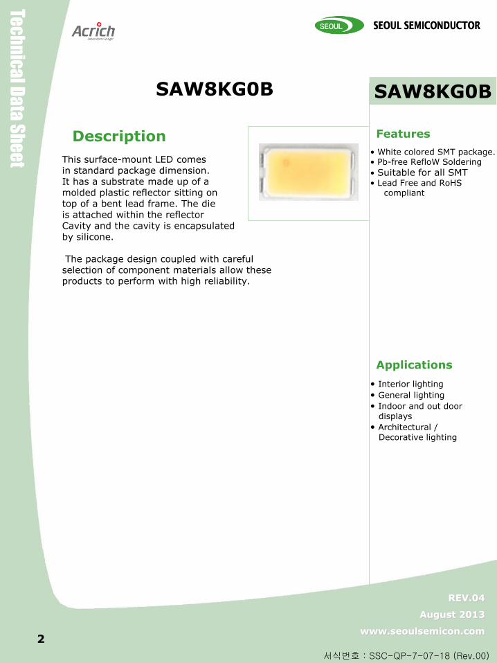
• White colored SMT package. • Pb-free RefloW Soldering
• Suitable for all SMT • Lead Free and RoHS
compliant
• Interior lighting
• General lighting
• Indoor and out door displays
• Architectural / Decorative lighting
Features
Applications
SAW8KG0B
사진
SAW8KG0B
Description
This surface-mount LED comes in standard package dimension. It has a substrate made up of a molded plastic reflector sitting on top of a bent lead frame. The die is attached within the reflector Cavity and the cavity is encapsulated by silicone. The package design coupled with careful selection of component materials allow these products to perform with high reliability.
Z-Po
we
r LED X
104
90
Z-P
ow
er LED
X10
49
0
Tec
hn
ica
l Da
ta S
he
et
REV.04
August 2013
www.seoulsemicon.com
서식번호 : SSC-QP-7-07-18 (Rev.00)
3
Contents
1. Outline dimensions
2. Characteristics of SAW8KG0B LED
3. Characteristic diagrams
4. Color & Binning
5. Bin Code Description
6. Labeling
7. Packing
8. Recommended solder pad
9. Soldering
10. Precaution for use
11. Handling of Silicone Resin LEDs
Z-Po
we
r LED X
104
90
Z-P
ow
er LED
X10
49
0
Tec
hn
ica
l Da
ta S
he
et
REV.04
August 2013
www.seoulsemicon.com
서식번호 : SSC-QP-7-07-18 (Rev.00)
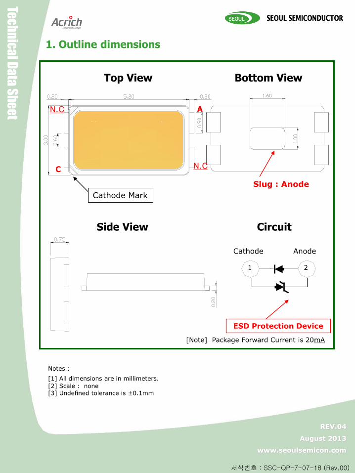
1. Outline dimensions
Notes :
[1] All dimensions are in millimeters.
[2] Scale : none [3] Undefined tolerance is ±0.1mm
Anode Cathode
2 1
ESD Protection Device
Cathode Mark
Top View Bottom View
Side View Circuit
A
C
N.C
N.C
Slug : Anode
[Note] Package Forward Current is 20mA
Z-Po
we
r LED X
104
90
Z-P
ow
er LED
X10
49
0
Tec
hn
ica
l Da
ta S
he
et
REV.04
August 2013
www.seoulsemicon.com
서식번호 : SSC-QP-7-07-18 (Rev.00)
5 5
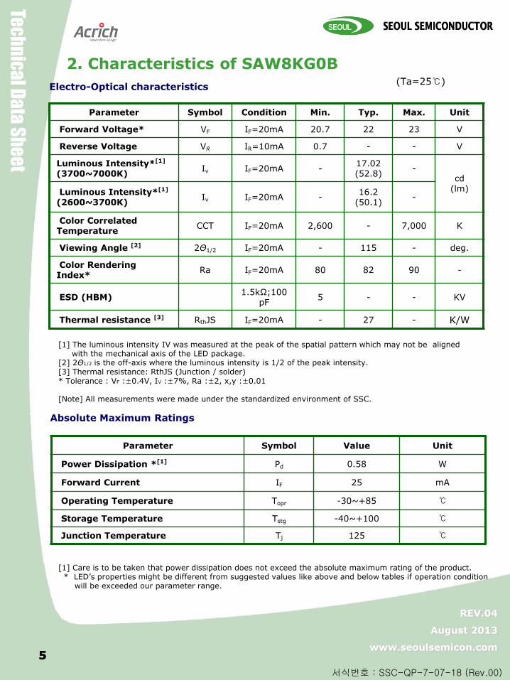
2. Characteristics of SAW8KG0B (Ta=25)
Parameter Symbol Condition Min. Typ. Max. Unit
Forward Voltage* VF IF=20mA 20.7 22 23 V
Reverse Voltage VR IR=10mA 0.7 - - V
Luminous Intensity*[1]
(3700~7000K) Iv IF=20mA - 17.02 (52.8)
- cd
(lm) Luminous Intensity*[1]
(2600~3700K) Iv IF=20mA -
16.2 (50.1)
-
Color Correlated Temperature
CCT IF=20mA 2,600 - 7,000 K
Viewing Angle [2] 2Θ1/2 IF=20mA - 115 - deg.
Color Rendering Index*
Ra IF=20mA 80 82 90 -
ESD (HBM) 1.5kΩ;100
pF 5 - - KV
Thermal resistance [3] RthJS IF=20mA - 27 - K/W
[1] The luminous intensity IV was measured at the peak of the spatial pattern which may not be aligned with the mechanical axis of the LED package. [2] 2Θ1/2 is the off-axis where the luminous intensity is 1/2 of the peak intensity. [3] Thermal resistance: RthJS (Junction / solder) * Tolerance : VF :±0.4V, IV :±7%, Ra :±2, x,y :±0.01 [Note] All measurements were made under the standardized environment of SSC.
Absolute Maximum Ratings
Electro-Optical characteristics
Parameter Symbol Value Unit
Power Dissipation *[1] Pd 0.58 W
Forward Current IF 25 mA
Operating Temperature Topr -30~+85
Storage Temperature Tstg -40~+100
Junction Temperature Tj 125
[1] Care is to be taken that power dissipation does not exceed the absolute maximum rating of the product. * LED’s properties might be different from suggested values like above and below tables if operation condition will be exceeded our parameter range.
Z-Po
we
r LED X
104
90
Z-P
ow
er LED
X10
49
0
Tec
hn
ica
l Da
ta S
he
et
REV.04
August 2013
www.seoulsemicon.com
서식번호 : SSC-QP-7-07-18 (Rev.00)
6 6
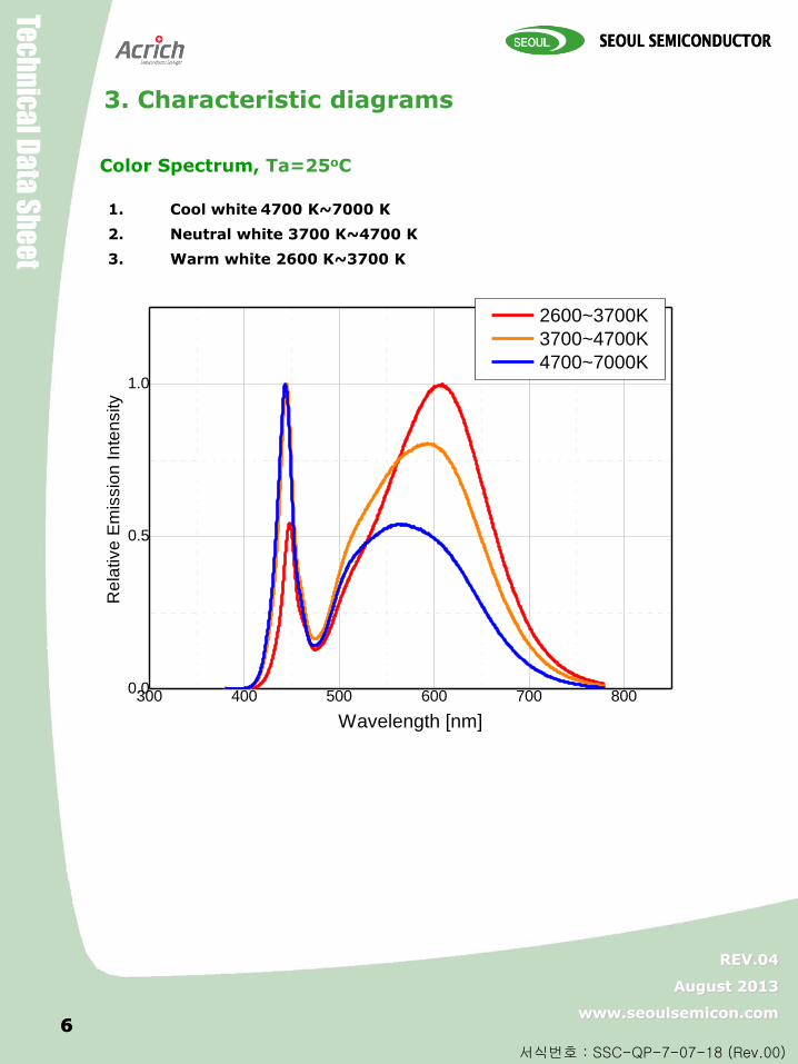
Color Spectrum, Ta=25oC
3. Characteristic diagrams
1. Cool white 4700 K~7000 K
2. Neutral white 3700 K~4700 K
3. Warm white 2600 K~3700 K
300 400 500 600 700 8000.0
0.5
1.0
2600~3700K
3700~4700K
4700~7000K
Re
lative
Em
issio
n In
ten
sity
Wavelength [nm]
Z-Po
we
r LED X
104
90
Z-P
ow
er LED
X10
49
0
Tec
hn
ica
l Da
ta S
he
et
REV.04
August 2013
www.seoulsemicon.com
서식번호 : SSC-QP-7-07-18 (Rev.00)
7 7
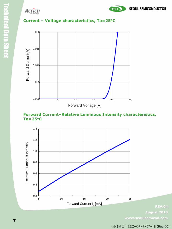
Current – Voltage characteristics, Ta=25oC
0 5 10 15 20 250.000
0.005
0.010
0.015
0.020
F
orw
ard
Curr
ent(
A)
Forward Voltage [V]
Forward Current–Relative Luminous Intensity characteristics, Ta=25oC
5 10 15 20 250.2
0.4
0.6
0.8
1.0
1.2
1.4
Re
lative
Lu
min
ou
s In
ten
sity
Forward Current IF [mA]
Z-Po
we
r LED X
104
90
Z-P
ow
er LED
X10
49
0
Tec
hn
ica
l Da
ta S
he
et
REV.04
August 2013
www.seoulsemicon.com
서식번호 : SSC-QP-7-07-18 (Rev.00)
8
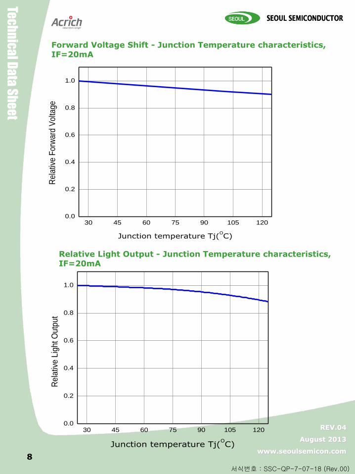
Relative Light Output - Junction Temperature characteristics, IF=20mA
Forward Voltage Shift - Junction Temperature characteristics, IF=20mA
30 45 60 75 90 105 1200.0
0.2
0.4
0.6
0.8
1.0
Re
lativ
e F
orw
ard
Vo
ltag
e
Junction temperature Tj(OC)
30 45 60 75 90 105 1200.0
0.2
0.4
0.6
0.8
1.0
Re
lativ
e L
igh
t O
utp
ut
Junction temperature Tj(OC)
Z-Po
we
r LED X
104
90
Z-P
ow
er LED
X10
49
0
Tec
hn
ica
l Da
ta S
he
et
REV.04
August 2013
www.seoulsemicon.com
서식번호 : SSC-QP-7-07-18 (Rev.00)
0.4392 0.4394 0.4396 0.4398 0.4400
0.411
0.412
0.413
0.414
0.415
y
x
9
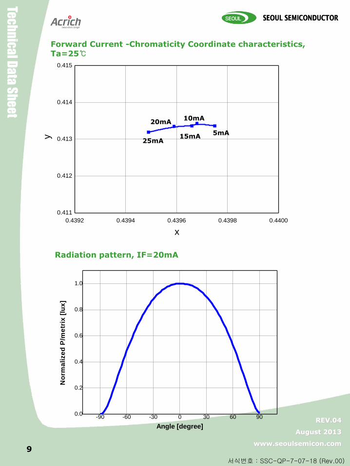
Forward Current -Chromaticity Coordinate characteristics, Ta=25
25mA
20mA
15mA
10mA
5mA
Radiation pattern, IF=20mA
-90 -60 -30 0 30 60 900.0
0.2
0.4
0.6
0.8
1.0
No
rma
lize
d P
/me
trix
[lu
x]
Angle [degree]
Z-Po
we
r LED X
104
90
Z-P
ow
er LED
X10
49
0
Tec
hn
ica
l Da
ta S
he
et
REV.04
August 2013
www.seoulsemicon.com
서식번호 : SSC-QP-7-07-18 (Rev.00)
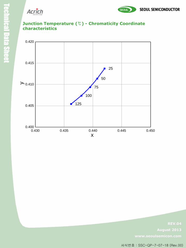
Junction Temperature () - Chromaticity Coordinate characteristics
0.430 0.435 0.440 0.445 0.4500.400
0.405
0.410
0.415
0.420
25
50
75
100
125
y
x
Z-Po
we
r LED X
104
90
Z-P
ow
er LED
X10
49
0
Tec
hn
ica
l Da
ta S
he
et
REV.04
August 2013
www.seoulsemicon.com
서식번호 : SSC-QP-7-07-18 (Rev.00)
11
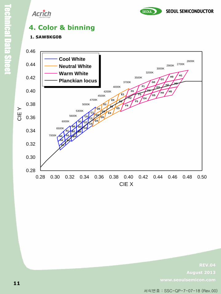
1. SAW8KG0B
4. Color & binning
0.28 0.30 0.32 0.34 0.36 0.38 0.40 0.42 0.44 0.46 0.48 0.50
0.28
0.30
0.32
0.34
0.36
0.38
0.40
0.42
0.44
0.46
Cool White
Neutral White
Warm White
Planckian locus
7000K
2600K2700K
2900K3000K
3200K
3500K
3700K
4000K
4200K
4500K
4700K
5000K
5300K
5600K
6000K
6500K
CIE X
CIE
Y
A5
A3
A1
A4
A2
A0
C0
C1
C2
C3
C4
C5B0
B1
B2
B3
B4
B5
D0
D1
D2
D3
D4
D5
F0
F1
F2
F3
F4
F5
G0G1
G2
G3
G4
G5
H0H1
H2H3
H4H5
E0
E1
E2
E3
E4
E5
Z-Po
we
r LED X
104
90
Z-P
ow
er LED
X10
49
0
Tec
hn
ica
l Da
ta S
he
et
REV.04
August 2013
www.seoulsemicon.com
서식번호 : SSC-QP-7-07-18 (Rev.00)
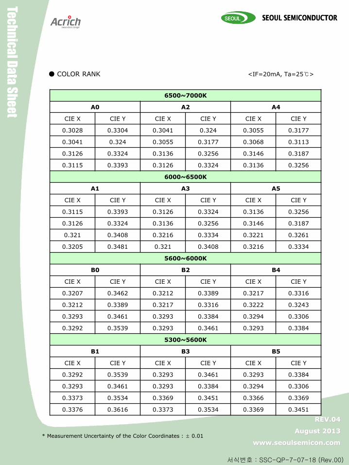
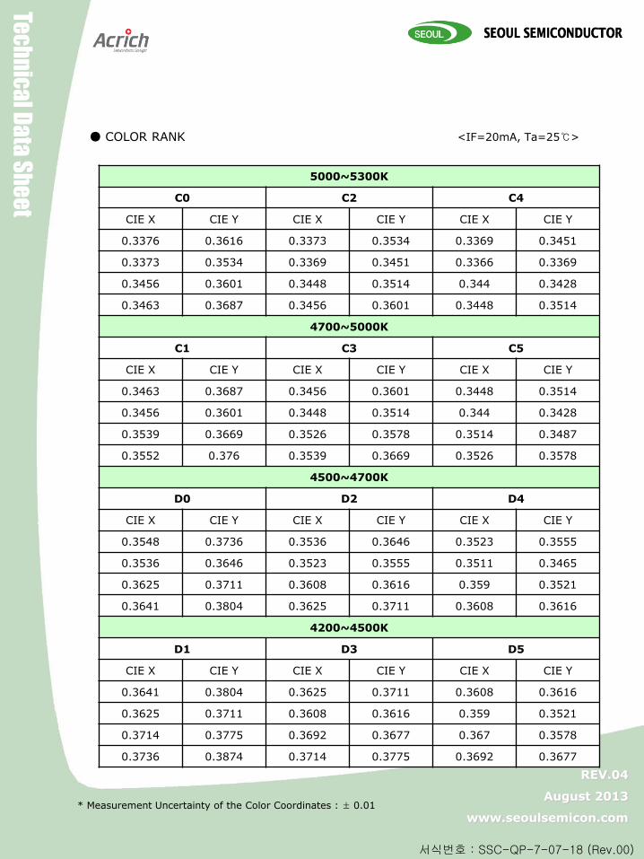
COLOR RANK <IF=20mA, Ta=25>
* Measurement Uncertainty of the Color Coordinates : ± 0.01
6500~7000K
A0 A2 A4
CIE X CIE Y CIE X CIE Y CIE X CIE Y
0.3028 0.3304 0.3041 0.324 0.3055 0.3177
0.3041 0.324 0.3055 0.3177 0.3068 0.3113
0.3126 0.3324 0.3136 0.3256 0.3146 0.3187
0.3115 0.3393 0.3126 0.3324 0.3136 0.3256
6000~6500K
A1 A3 A5
CIE X CIE Y CIE X CIE Y CIE X CIE Y
0.3115 0.3393 0.3126 0.3324 0.3136 0.3256
0.3126 0.3324 0.3136 0.3256 0.3146 0.3187
0.321 0.3408 0.3216 0.3334 0.3221 0.3261
0.3205 0.3481 0.321 0.3408 0.3216 0.3334
5600~6000K
B0 B2 B4
CIE X CIE Y CIE X CIE Y CIE X CIE Y
0.3207 0.3462 0.3212 0.3389 0.3217 0.3316
0.3212 0.3389 0.3217 0.3316 0.3222 0.3243
0.3293 0.3461 0.3293 0.3384 0.3294 0.3306
0.3292 0.3539 0.3293 0.3461 0.3293 0.3384
5300~5600K
B1 B3 B5
CIE X CIE Y CIE X CIE Y CIE X CIE Y
0.3292 0.3539 0.3293 0.3461 0.3293 0.3384
0.3293 0.3461 0.3293 0.3384 0.3294 0.3306
0.3373 0.3534 0.3369 0.3451 0.3366 0.3369
0.3376 0.3616 0.3373 0.3534 0.3369 0.3451
Z-Po
we
r LED X
104
90
Z-P
ow
er LED
X10
49
0
Tec
hn
ica
l Da
ta S
he
et
REV.04
August 2013
www.seoulsemicon.com
서식번호 : SSC-QP-7-07-18 (Rev.00)
COLOR RANK
* Measurement Uncertainty of the Color Coordinates : ± 0.01
5000~5300K
C0 C2 C4
CIE X CIE Y CIE X CIE Y CIE X CIE Y
0.3376 0.3616 0.3373 0.3534 0.3369 0.3451
0.3373 0.3534 0.3369 0.3451 0.3366 0.3369
0.3456 0.3601 0.3448 0.3514 0.344 0.3428
0.3463 0.3687 0.3456 0.3601 0.3448 0.3514
4700~5000K
C1 C3 C5
CIE X CIE Y CIE X CIE Y CIE X CIE Y
0.3463 0.3687 0.3456 0.3601 0.3448 0.3514
0.3456 0.3601 0.3448 0.3514 0.344 0.3428
0.3539 0.3669 0.3526 0.3578 0.3514 0.3487
0.3552 0.376 0.3539 0.3669 0.3526 0.3578
4500~4700K
D0 D2 D4
CIE X CIE Y CIE X CIE Y CIE X CIE Y
0.3548 0.3736 0.3536 0.3646 0.3523 0.3555
0.3536 0.3646 0.3523 0.3555 0.3511 0.3465
0.3625 0.3711 0.3608 0.3616 0.359 0.3521
0.3641 0.3804 0.3625 0.3711 0.3608 0.3616
4200~4500K
D1 D3 D5
CIE X CIE Y CIE X CIE Y CIE X CIE Y
0.3641 0.3804 0.3625 0.3711 0.3608 0.3616
0.3625 0.3711 0.3608 0.3616 0.359 0.3521
0.3714 0.3775 0.3692 0.3677 0.367 0.3578
0.3736 0.3874 0.3714 0.3775 0.3692 0.3677
<IF=20mA, Ta=25>

Z-Po
we
r LED X
104
90
Z-P
ow
er LED
X10
49
0
Tec
hn
ica
l Da
ta S
he
et
REV.04
August 2013
www.seoulsemicon.com
서식번호 : SSC-QP-7-07-18 (Rev.00)
COLOR RANK
* Measurement Uncertainty of the Color Coordinates : ± 0.01
4000~4200K
E0 E2 E4
CIE X CIE Y CIE X CIE Y CIE X CIE Y
0.3736 0.3874 0.3714 0.3775 0.3692 0.3677
0.3714 0.3775 0.3692 0.3677 0.367 0.3578
0.3842 0.3855 0.3813 0.3751 0.3783 0.3646
0.3869 0.3958 0.3842 0.3855 0.3813 0.3751
3700~4000K
E1 E3 E5
CIE X CIE Y CIE X CIE Y CIE X CIE Y
0.3869 0.3958 0.3842 0.3855 0.3813 0.3751
0.3842 0.3855 0.3813 0.3751 0.3783 0.3646
0.397 0.3935 0.3934 0.3825 0.3898 0.3716
0.4006 0.4044 0.397 0.3935 0.3934 0.3825
3500~3700K
F0 F2 F4
CIE X CIE Y CIE X CIE Y CIE X CIE Y
0.3996 0.4015 0.396 0.3907 0.3925 0.3798
0.396 0.3907 0.3925 0.3798 0.3889 0.369
0.4104 0.3978 0.4062 0.3865 0.4017 0.3751
0.4146 0.4089 0.4104 0.3978 0.4062 0.3865
3200~3500K
F1 F3 F5
CIE X CIE Y CIE X CIE Y CIE X CIE Y
0.4146 0.4089 0.4104 0.3978 0.4062 0.3865
0.4104 0.3978 0.4062 0.3865 0.4017 0.3751
0.4248 0.4048 0.4198 0.3931 0.4147 0.3814
0.4299 0.4165 0.4248 0.4048 0.4198 0.3931
<IF=20mA, Ta=25>
Z-Po
we
r LED X
104
90
Z-P
ow
er LED
X10
49
0
Tec
hn
ica
l Da
ta S
he
et
REV.04
August 2013
www.seoulsemicon.com
서식번호 : SSC-QP-7-07-18 (Rev.00)
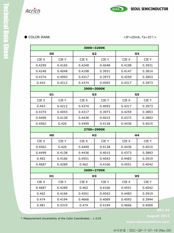
COLOR RANK
* Measurement Uncertainty of the Color Coordinates : ± 0.01
3000~3200K
G0 G2 G4
CIE X CIE Y CIE X CIE Y CIE X CIE Y
0.4299 0.4165 0.4248 0.4048 0.4198 0.3931
0.4248 0.4048 0.4198 0.3931 0.4147 0.3814
0.4374 0.4093 0.4317 0.3973 0.4259 0.3853
0.443 0.4212 0.4374 0.4093 0.4317 0.3973
2900~3000K
G1 G3 G5
CIE X CIE Y CIE X CIE Y CIE X CIE Y
0.443 0.4212 0.4374 0.4093 0.4317 0.3973
0.4374 0.4093 0.4317 0.3973 0.4259 0.3853
0.4499 0.4138 0.4436 0.4015 0.4373 0.3893
0.4562 0.426 0.4499 0.4138 0.4436 0.4015
2700~2900K
H0 H2 H4
CIE X CIE Y CIE X CIE Y CIE X CIE Y
0.4562 0.426 0.4499 0.4138 0.4436 0.4015
0.4499 0.4138 0.4436 0.4015 0.4373 0.3893
0.462 0.4166 0.4551 0.4042 0.4483 0.3919
0.4687 0.4289 0.462 0.4166 0.4551 0.4042
2600~2700K
H1 H3 H5
CIE X CIE Y CIE X CIE Y CIE X CIE Y
0.4687 0.4289 0.462 0.4166 0.4551 0.4042
0.462 0.4166 0.4551 0.4042 0.4483 0.3919
0.474 0.4194 0.4666 0.4069 0.4593 0.3944
0.481 0.4319 0.474 0.4194 0.4666 0.4069
<IF=20mA, Ta=25>
Z-Po
we
r LED X
104
90
Z-P
ow
er LED
X10
49
0
Tec
hn
ica
l Da
ta S
he
et
REV.04
August 2013
www.seoulsemicon.com
서식번호 : SSC-QP-7-07-18 (Rev.00)
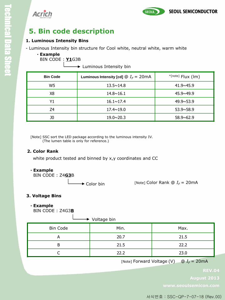
5. Bin code description
1. Luminous Intensity Bins
- Luminous Intensity bin structure for Cool white, neutral white, warm white
Bin Code Luminous Intensity [cd] @ IF = 20mA *[note] Flux (lm)
W5 13.5~14.8 41.9~45.9
X8 14.8~16.1 45.9~49.9
Y1 16.1~17.4 49.9~53.9
Z4 17.4~19.0 53.9~58.9
J0 19.0~20.3 58.9~62.9
· Example BIN CODE : Y1G3B
Luminous Intensity bin
2. Color Rank
white product tested and binned by x,y coordinates and CC
· Example BIN CODE : Z4G3B
Color bin
[Note] SSC sort the LED package according to the luminous intensity IV. (The lumen table is only for reference.)
[Note] Color Rank @ IF = 20mA
3. Voltage Bins
Bin Code Min. Max.
A 20.7 21.5
B 21.5 22.2
C 22.2 23.0
[Note] Forward Voltage (V) @ IF = 20mA
· Example BIN CODE : Z4G3B
Voltage bin

Z-Po
we
r LED X
104
90
Z-P
ow
er LED
X10
49
0
Tec
hn
ica
l Da
ta S
he
et
REV.04
August 2013
www.seoulsemicon.com
서식번호 : SSC-QP-7-07-18 (Rev.00)
6. Labeling
SAW8KG0B
3,500
Z-Po
we
r LED X
104
90
Z-P
ow
er LED
X10
49
0
Tec
hn
ica
l Da
ta S
he
et
REV.04
August 2013
www.seoulsemicon.com
서식번호 : SSC-QP-7-07-18 (Rev.00)
18
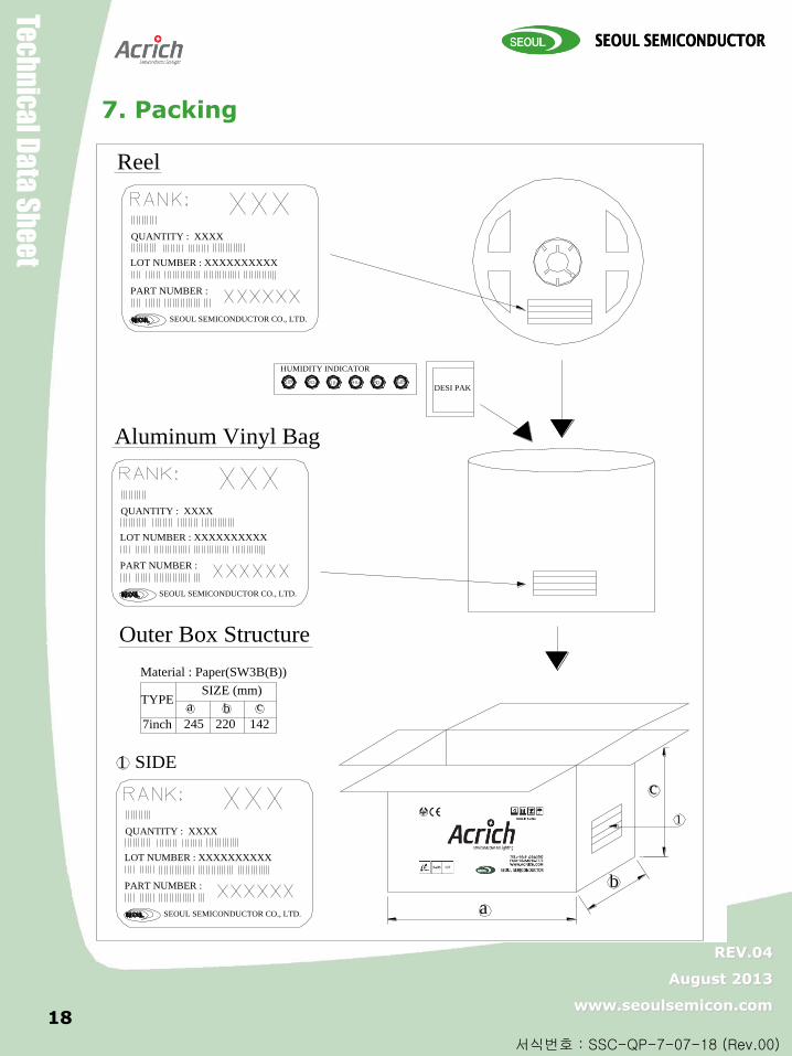
7. Packing
ca b
1 SIDE
7inch 245 220 142
SIZE (mm)
Outer Box Structure
Material : Paper(SW3B(B))
TYPE
a
b
c
1
HUMIDITY INDICATOR
Aluminum Vinyl Bag
Reel
DESI PAK
PART NUMBER :
LOT NUMBER : XXXXXXXXXX
QUANTITY : XXXX
SEOUL SEMICONDUCTOR CO., LTD.
PART NUMBER :
LOT NUMBER : XXXXXXXXXX
QUANTITY : XXXX
SEOUL SEMICONDUCTOR CO., LTD.
PART NUMBER :
LOT NUMBER : XXXXXXXXXX
QUANTITY : XXXX
SEOUL SEMICONDUCTOR CO., LTD.
RoHS
Z-Po
we
r LED X
104
90
Z-P
ow
er LED
X10
49
0
Tec
hn
ica
l Da
ta S
he
et
REV.04
August 2013
www.seoulsemicon.com
서식번호 : SSC-QP-7-07-18 (Rev.00)
19
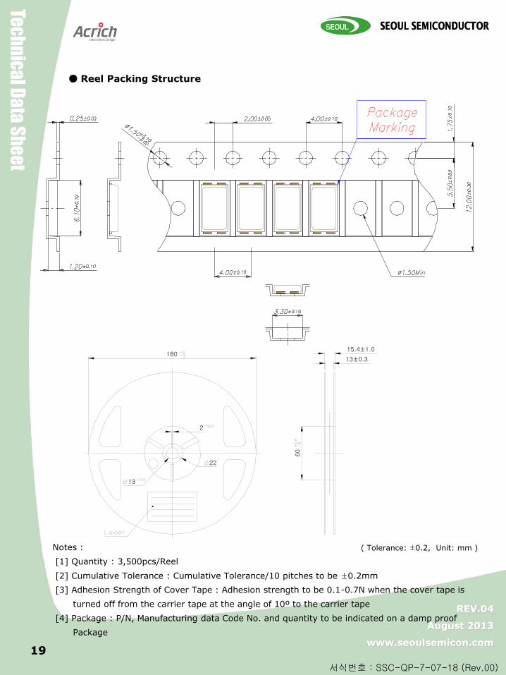
Reel Packing Structure
180
2
13
22
60
15.4±1.0
13±0.3
( Tolerance: ±0.2, Unit: mm ) Notes :
[1] Quantity : 3,500pcs/Reel
[2] Cumulative Tolerance : Cumulative Tolerance/10 pitches to be ±0.2mm
[3] Adhesion Strength of Cover Tape : Adhesion strength to be 0.1-0.7N when the cover tape is
turned off from the carrier tape at the angle of 10º to the carrier tape
[4] Package : P/N, Manufacturing data Code No. and quantity to be indicated on a damp proof
Package

Z-Po
we
r LED X
104
90
Z-P
ow
er LED
X10
49
0
Tec
hn
ica
l Da
ta S
he
et
REV.04
August 2013
www.seoulsemicon.com
서식번호 : SSC-QP-7-07-18 (Rev.00)
8. Recommended solder pad
Notes :
[1] All dimensions are in millimeters.
[2] Scale : none [3] Undefined tolerance is ±0.1mm This drawing without tolerances are for reference only.

Z-Po
we
r LED X
104
90
Z-P
ow
er LED
X10
49
0
Tec
hn
ica
l Da
ta S
he
et
REV.04
August 2013
www.seoulsemicon.com
서식번호 : SSC-QP-7-07-18 (Rev.00)
21 21
9. Soldering
* Caution 1. Reflow soldering is recommended not to be done more than two times. In the case of more than 24 hours passed soldering after first, LEDs will be damaged.
2. Repairs should not be done after the LEDs have been soldered. When repair is unavoidable, suitable tools must be used. 3. Die slug is to be soldered. 4. When soldering, do not put stress on the LEDs during heating. 5. After soldering, do not warp the circuit board.
IPC/JEDEC J-STD-020
Profile Feature Sn-Pb Eutectic Assembly Pb-Free Assembly
Average ramp-up rate (Tsmax to Tp) 3° C/second max. 3° C/second max.
Preheat - Temperature Min (Tsmin) - Temperature Max (Tsmax) - Time (Tsmin to Tsmax) (ts)
100 °C 150 °C 60-120 seconds
150 °C 200 °C 60-180 seconds
Time maintained above: - Temperature (TL) - Time (tL)
183 °C 60-150 seconds
217 °C 60-150 seconds
Peak Temperature (Tp) 215 260
Time within 5°C of actual Peak Temperature (tp)2
10-30 seconds 20-40 seconds
Ramp-down Rate 6 °C/second max. 6 °C/second max.
Time 25°C to Peak Temperature 6 minutes max. 8 minutes max.
Z-Po
we
r LED X
104
90
Z-P
ow
er LED
X10
49
0
Tec
hn
ica
l Da
ta S
he
et
REV.04
August 2013
www.seoulsemicon.com
서식번호 : SSC-QP-7-07-18 (Rev.00)
22 22
(1) Storage
To avoid the moisture penetration, we recommend storing SSC LEDs in a dry box
with a desiccant . The recommended storage temperature range is 5 to 30 and a maximum
humidity of RH50%.
(2) Use Precaution after Opening the Packaging
Use proper SMD techniques when the LED is to be soldered dipped as separation of the lens
may affect the light output efficiency.
Pay attention to the following:
a. Recommend conditions after opening the package
- Sealing
- Temperature : 5 ~ 40 Humidity : less than RH30%
b. If the package has been opened more than 4 week(MSL_2a) or the color of the
desiccant changes, components should be dried for 10-12hr at 60±5
(3) Do not apply mechanical force or excess vibration during the cooling process to normal
temperature after soldering.
(4) Do not rapidly cool device after soldering.
(5) Components should not be mounted on warped (non coplanar) portion of PCB.
(6) Radioactive exposure is not considered for the products listed here in.
(7) Gallium arsenide is used in some of the products listed in this publication. These products
are dangerous if they are burned or shredded in the process of disposal. It is also dangerous to
drink the liquid or inhale the gas generated by such products when chemically disposed of.
(8) This device should not be used in any type of fluid such as water, oil, organic solvent and
etc. When washing is required, IPA (Isopropyl Alcohol) should be used.
(9) When the LEDs are in operation the maximum current should be decided after measuring
the package temperature.
(10) LEDs must be stored properly to maintain the device. If the LEDs are stored for 3 months
or more after being shipped from SSC, a sealed container with a nitrogen atmosphere should
be used for storage.
(11) The appearance and specifications of the product may be modified for improvement
without notice.
(12) Long time exposure of sunlight or occasional UV exposure will cause lens discoloration.
(13) VOCs (Volatile organic compounds) emitted from materials used in the construction of
fixtures can penetrate silicone encapsulants of LEDs and discolor when exposed to heat and
photonic energy. The result can be a significant loss of light output from the fixture.
Knowledge of the properties of the materials selected to be used in the construction of fixtures
can help prevent these issues.
10. Precaution for use
Z-Po
we
r LED X
104
90
Z-P
ow
er LED
X10
49
0
Tec
hn
ica
l Da
ta S
he
et
REV.04
August 2013
www.seoulsemicon.com
서식번호 : SSC-QP-7-07-18 (Rev.00)
23
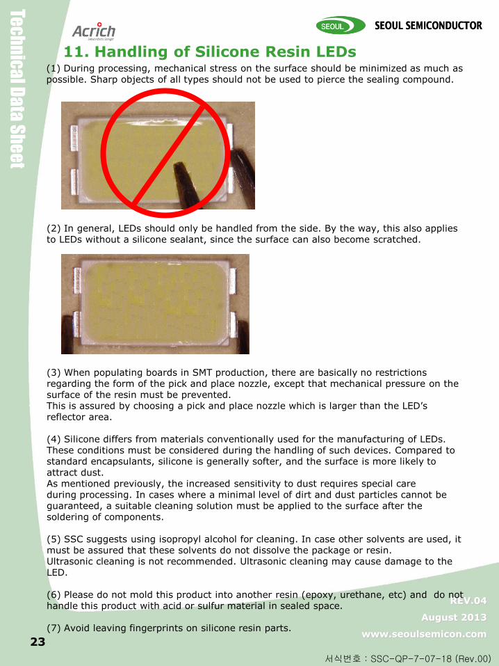
11. Handling of Silicone Resin LEDs (1) During processing, mechanical stress on the surface should be minimized as much as possible. Sharp objects of all types should not be used to pierce the sealing compound.
(2) In general, LEDs should only be handled from the side. By the way, this also applies to LEDs without a silicone sealant, since the surface can also become scratched.
(3) When populating boards in SMT production, there are basically no restrictions regarding the form of the pick and place nozzle, except that mechanical pressure on the surface of the resin must be prevented. This is assured by choosing a pick and place nozzle which is larger than the LED’s reflector area. (4) Silicone differs from materials conventionally used for the manufacturing of LEDs. These conditions must be considered during the handling of such devices. Compared to standard encapsulants, silicone is generally softer, and the surface is more likely to attract dust. As mentioned previously, the increased sensitivity to dust requires special care during processing. In cases where a minimal level of dirt and dust particles cannot be guaranteed, a suitable cleaning solution must be applied to the surface after the soldering of components. (5) SSC suggests using isopropyl alcohol for cleaning. In case other solvents are used, it must be assured that these solvents do not dissolve the package or resin. Ultrasonic cleaning is not recommended. Ultrasonic cleaning may cause damage to the LED. (6) Please do not mold this product into another resin (epoxy, urethane, etc) and do not handle this product with acid or sulfur material in sealed space. (7) Avoid leaving fingerprints on silicone resin parts.