Embed Size (px)
Citation preview
Standard-Spindelhubgetriebe Schnell-Spindelhubgetriebe Standard-Screw Jacks High Speed-Screw Jacks
Seiten | pages Q 1 - Q 4
GabelkopfSteel Clevis
Seiten | pages Q 6
StehlagerPedestal Bearing
Seiten | pages Q 13
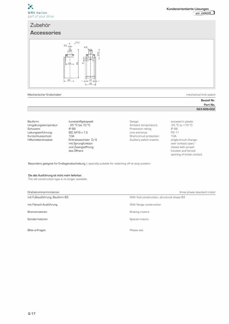
EndschalterMechanical Limit Switch
Seiten | pages Q 17
BefestigungsplatteSteel Top Plate
Seiten | pages Q 6
SicherheitsfangmutternSafety Nuts
Seiten | pages Q 11 - Q 12
MotorglockenMotor Flanges
Seiten | pages Q 16
FlanschmutterFlanged Nut
Seiten | pages Q 6
FaltenbälgeExpansion Bellows
Seiten | pages Q 7 - Q 10
GelenkwellenCardan Shafts
Seiten | pages Q 14 - Q 15
AnfrageformularInquiry Form
Seiten | pages Q 26 - Q 28
Schwenkplatte Swivel Plate
Seiten | pages Q 5
StangenkopfRod Head
Seiten | pages Q 6
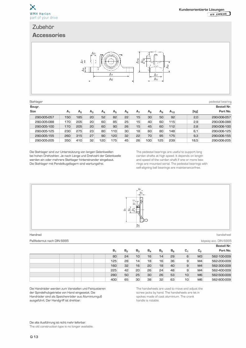
HandradHandwheel
Seiten | pages Q 13
SpindelhubgetriebeTechnische DatenScrew Jacks Technical Data
Seiten | pages Q 18 - Q 25
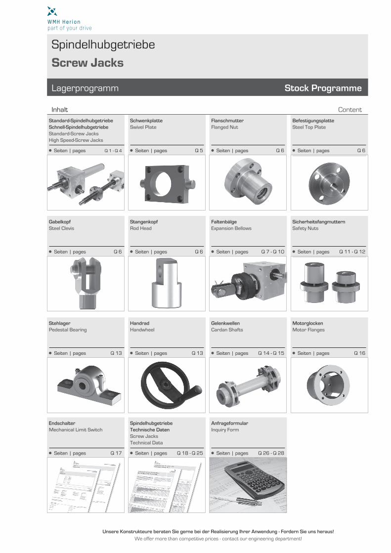
Spindelhubgetriebe
Screw Jacks
Lagerprogramm
Content
Stock Programme
Inhalt
Unsere Konstrukteure beraten Sie gerne bei der Realisierung Ihrer Anwendung - Fordern Sie uns heraus!
We offer more than competitive prices - contact our engineering department!
Q
Inhalt
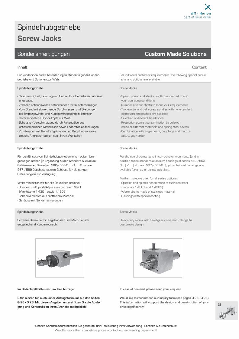
Spindelhubgetriebe
Screw Jacks
Für kundenindividuelle Anforderungen stehen folgende Sonder-
getriebe und Optionen zur Wahl:
Spindelhubgetriebe
Spindelhubgetriebe
Spindelhubgetriebe
Im Bedarfsfall bitten wir um Ihre Anfrage.
- Geschwindigkeit, Leistung und Hub an Ihre Betriebsverhältnisse
angepasst
- Zahl der Antriebswellen entsprechend Ihren Anforderungen
- Vom Standard abweichende Durchmesser und Steigungen
bei Trapezgewinde- und Kugelgewindespindeln lieferbar
- Unterschiedliche Spindelköpfe zur Wahl
- Schutz vor Verschmutzung durch Faltenbälge aus
unterschiedlichen Materialien sowie Federstahlabdeckungen
- Kombination mit Kegelradgetrieben und Kupplungen sowie
einschl. Antriebsmotoren nach Ihren Wünschen
Für den Einsatz von Spindelhubgetrieben in korrosiven Um-
gebungen stehen (in Ergänzung zu den Standard-Aluminium-
Gehäusen der Baureihen 562-/563-0.. | -1.. | -2.. sowie
567-/569-0..) phosphatierte Gehäuse für die übrigen
Getriebetypen zur Verfügung.
Weiterhin bieten wir für alle Baureihen optional:
- Spindeln und Spindelköpfe aus rostfreiem Stahl
(Werkstoffe 1.4301 sowie 1.4305)
- Schneckenwellen aus rostfreiem Material
- Gehäuse mit Sonderlackierungen
Schwere Baureihe mit Kegelradsatz und Motorfl ansch
entsprechend Kundenwunsch.
Bitte nutzen Sie auch unser Anfrageformular auf den Seiten
Q 26 - Q 28. Mit diesen Angaben unterstützen Sie die Ausle-
gung und Konstruktion Ihres Antriebs maßgeblich!
- Speed, power and stroke length customized to suit
your operating conditions
- Number of input shafts to meet your requirements
- Trapezoidal and ball screw spindles with non-standard
diameters and pitches are available
- Selection of different head types
- Protection against contamination by bellows
made of different materials and spring steel covers
- Combination with angle gears, couplings and motors
acc. to your order
For the use of screw jacks in corrosive environments (and in
addition to the standard aluminum housings of series 562-/563-
0 .. | -1 .. | -2 .. and 567-/569-0 ..), phosphatised housings are
available for all other screw jack sizes.
Furthermore, we offer for all series optional:
- Spindles and spindle heads made of stainless steel
(materials 1.4301 and 1.4305)
- Worm shafts made of stainless material
- Housings with special coating
Heavy duty series with bevel gears and motor fl ange to
customers design.
We´d like to recommend our inquiry form (see pages Q 26 - Q 28).
This information will support the design and construction of your
drive signifi cantly!
For individual customer requirements, the following special screw
jacks and options are available:
Screw Jacks
Screw Jacks
Screw Jacks
In case of demand, please send your request.
Sonderanfertigungen Custom Made Solutions
Content
Unsere Konstrukteure beraten Sie gerne bei der Realisierung Ihrer Anwendung - Fordern Sie uns heraus!
We offer more than competitive prices - contact our engineering department!
Q 1
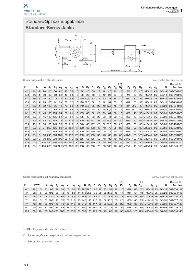
Standard-Spindelhubgetriebe
Standard-Screw Jacks
i* Tr A A1 A2 A3 a1 a2 a3 B B1 C1 C2 C3 C4 C5
(k6)D1 D2 D3
dD4 d1 d3 Q
Bestell Nr. Part No.
i* KGT 1) A A1 A2 A3 a1 a2 a3 B B1 C1 C2 C3 C4 C5
(k6)D1 D2 D3 D4** d1 d3 Q
Bestell Nr. Part No.
4:1 14x 4 20 60 50 22 48 38 6 92 20 50 12 12 25 27 9 M8 26 28 M6x12 25 3x3x14 562-004-010
16:1 14x 4 20 60 50 22 48 38 6 92 20 50 12 12 25 27 9 M8 26 28 M6x12 25 3x3x14 562-016-010
4:1 18x 4 25 80 72 31 60 52 10 120 22,5 62 19 12 31 35 10 M12 30 32 M8x13 25 3x3x18 562-104-012
16:1 18x 4 25 80 72 31 60 52 10 120 22,5 62 19 12 31 35 10 M12 30 32 M8x13 25 3x3x18 562-116-012
4:1 20x 4 32 100 85 40 78 63 11 140 25,5 75 20 18 37,5 45 14 M14 38,7 40 M8x15 35 5x5x20 562-204-015
16:1 20x 4 32 100 85 40 78 63 11 140 25,5 75 20 18 37,5 45 14 M14 38,7 40 M8x15 35 5x5x20 562-216-015
6:1 30x 6 45 130 105 54 106 81 12 195 43 82 22 23 41 50 16 M20 46 50 M10x15 35 5x5x36 562-306-020
24:1 30x 6 45 130 105 54 106 81 12 195 43 82 22 23 41 50 16 M20 46 50 M10x15 35 5x5x36 562-324-020
7:1 40x 7 63 180 145 78 150 115 15 240 45 117 29 32 58,5 65 20 M30 60 65 M12x16 50 6x6x36 562-407-025
28:1 40x 7 63 180 145 78 150 115 15 240 45 117 29 32 58,5 65 20 M30 60 65 M12x16 50 6x6x36 562-428-025
9:1 60x 9 71 200 165 83 166 131 17 300 65 160 48 40 79 95 25 M36 85 90 M20x30 60 8x7x56 562-509-040
36:1 60x 9 71 200 165 83 166 131 17 300 65 160 48 40 79 95 25 M36 85 90 M20x30 60 8x7x56 562-536-040
10:1 80x 10 80 240 220 100 190 170 25 355 65 165 58 40 82 110 30 M64x3 120 125 M30x45 60 8x7x56 562-810-075
40:1 80x 10 80 240 220 100 190 170 25 355 65 165 58 40 82 110 30 M64x3 120 125 M30x45 60 8x7x56 562-840-075
10:1 100x 10 100 290 250 125 230 190 30 380 63 220 78 50 106 140 35 M72x3 145 150 M36x54 70 10x8x56 562-910-100
40:1 100x 10 100 290 250 125 230 190 30 380 63 220 78 50 106 140 35 M72x3 145 150 M36x54 70 10x8x56 562-940-100
4:1 16x 5 25 80 72 31 60 52 10 120 22,5 62 19 25 31 48 10 M12 48 32 M8x13 25 3x3x18 562-004-112
4:1 20x 5 32 100 85 40 78 63 11 140 25,5 75 20 22 37,5 49 14 M14 57 40 M8x15 35 5x5x20 562-004-115
6:1 25x 5 45 130 105 54 106 81 12 195 43 82 22 23 41 50 16 M20 46 50 M10x15 35 5x5x36 562-006-120
7:1 40x 5 63 180 145 78 150 115 15 240 45 117 29 32 58,5 65 20 M30 60 65 M12x16 50 6x6x36 562-007-124
7:1 40x 10 63 180 145 78 150 115 15 240 45 117 29 32 58,5 65 20 M30 60 65 M12x16 50 6x6x36 562-007-126
9:1 50x 10 71 200 165 83 166 131 17 300 65 160 48 40 79 95 25 M36 85 90 M20x30 60 8x7x56 562-009-130
10:1 80x 10 80 240 220 100 190 170 25 355 65 165 58 40 82 110 30 M64x3 120 125 M30x45 60 8x7x56 562-010-140
1) KGT = Kugelgewindetrieb | ball screw size i*: Übersetzung-Schneckengetriebe | ratio-worm gear reducer **: Schutzrohr | protecting tube
Spindelhubgetriebe - hebende Spindel screw jacks - traveling screw
Spindelhubgetriebe mit Kugelgewindespindel screw jacks with ball screws
Kundenorientierte Lösungen
AUF ANFRAGE
Q 2
Q
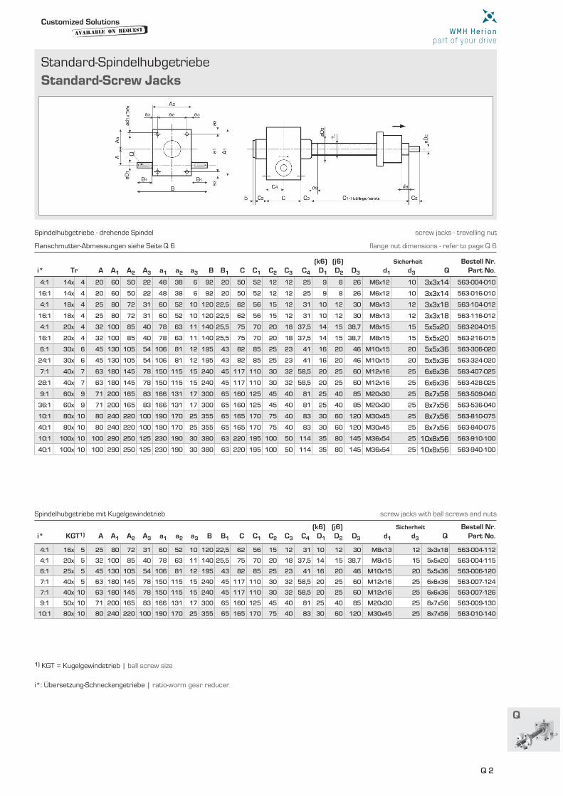
Standard-Spindelhubgetriebe
Standard-Screw Jacks
i* Tr A A1 A2 A3 a1 a2 a3 B B1 C C1 C2 C3 C4
(k6)D1
(j6)D2 D3
dd1
Sicherheit
d3 QBestell Nr.
Part No.
4:1 14x 4 20 60 50 22 48 38 6 92 20 50 52 12 12 25 9 8 26 M6x12 10 3x3x14 563-004-010
16:1 14x 4 20 60 50 22 48 38 6 92 20 50 52 12 12 25 9 8 26 M6x12 10 3x3x14 563-016-010
4:1 18x 4 25 80 72 31 60 52 10 120 22,5 62 56 15 12 31 10 12 30 M8x13 12 3x3x18 563-104-012
16:1 18x 4 25 80 72 31 60 52 10 120 22,5 62 56 15 12 31 10 12 30 M8x13 12 3x3x18 563-116-012
4:1 20x 4 32 100 85 40 78 63 11 140 25,5 75 70 20 18 37,5 14 15 38,7 M8x15 15 5x5x20 563-204-015
16:1 20x 4 32 100 85 40 78 63 11 140 25,5 75 70 20 18 37,5 14 15 38,7 M8x15 15 5x5x20 563-216-015
6:1 30x 6 45 130 105 54 106 81 12 195 43 82 85 25 23 41 16 20 46 M10x15 20 5x5x36 563-306-020
24:1 30x 6 45 130 105 54 106 81 12 195 43 82 85 25 23 41 16 20 46 M10x15 20 5x5x36 563-324-020
7:1 40x 7 63 180 145 78 150 115 15 240 45 117 110 30 32 58,5 20 25 60 M12x16 25 6x6x36 563-407-025
28:1 40x 7 63 180 145 78 150 115 15 240 45 117 110 30 32 58,5 20 25 60 M12x16 25 6x6x36 563-428-025
9:1 60x 9 71 200 165 83 166 131 17 300 65 160 125 45 40 81 25 40 85 M20x30 25 8x7x56 563-509-040
36:1 60x 9 71 200 165 83 166 131 17 300 65 160 125 45 40 81 25 40 85 M20x30 25 8x7x56 563-536-040
10:1 80x 10 80 240 220 100 190 170 25 355 65 165 170 75 40 83 30 60 120 M30x45 25 8x7x56 563-810-075
40:1 80x 10 80 240 220 100 190 170 25 355 65 165 170 75 40 83 30 60 120 M30x45 25 8x7x56 563-840-075
10:1 100x 10 100 290 250 125 230 190 30 380 63 220 195 100 50 114 35 80 145 M36x54 25 10x8x56 563-910-100
40:1 100x 10 100 290 250 125 230 190 30 380 63 220 195 100 50 114 35 80 145 M36x54 25 10x8x56 563-940-100
i* KGT1) A A1 A2 A3 a1 a2 a3 B B1 C C1 C2 C3 C4
(k6)D1
(j6)D2 D3
dd1
Sicherheit
d3 QBestell Nr.
Part No.
4:1 16x 5 25 80 72 31 60 52 10 120 22,5 62 56 15 12 31 10 12 30 M8x13 12 3x3x18 563-004-112
4:1 20x 5 32 100 85 40 78 63 11 140 25,5 75 70 20 18 37,5 14 15 38,7 M8x15 15 5x5x20 563-004-115
6:1 25x 5 45 130 105 54 106 81 12 195 43 82 85 25 23 41 16 20 46 M10x15 20 5x5x36 563-006-120
7:1 40x 5 63 180 145 78 150 115 15 240 45 117 110 30 32 58,5 20 25 60 M12x16 25 6x6x36 563-007-124
7:1 40x 10 63 180 145 78 150 115 15 240 45 117 110 30 32 58,5 20 25 60 M12x16 25 6x6x36 563-007-126
9:1 50x 10 71 200 165 83 166 131 17 300 65 160 125 45 40 81 25 40 85 M20x30 25 8x7x56 563-009-130
10:1 80x 10 80 240 220 100 190 170 25 355 65 165 170 75 40 83 30 60 120 M30x45 25 8x7x56 563-010-140
1) KGT = Kugelgewindetrieb | ball screw size
i*: Übersetzung-Schneckengetriebe | ratio-worm gear reducer
Flanschmutter-Abmessungen siehe Seite Q 6 fl ange nut dimensions - refer to page Q 6
Spindelhubgetriebe - drehende Spindel screw jacks - travelling nut
Spindelhubgetriebe mit Kugelgewindetrieb screw jacks with ball screws and nuts
Customized Solutionsavailable on
Request
Q 3
Schnell-Spindelhubgetriebe
High Speed-Screw Jacks
i Tr A A1
2)
A2 A3 A4 A5 B1 B2 C1 C2
3)
C3
4)
D1f7 D2
5)
D3h7 D4 D5 D6 D7 D8
j6 D9 D10 D11 D12 Q
Bestell Nr.
Part No.
i KGT1) A A1
2)
A2 A3 A4 A5 B1 B2 C1 C2
3)
C3
4)
D1f7 D2
5)
D3h7 D4 D5 D6
6)
D7 D8j6 D9 D10 D11 D12 Q
Bestell Nr.
Part No.
2:1 24x 5 90 140 50 23 22 35 - - 122 87 10 60 75 90 38,7 M18 M8 40 18 M10 72 - - A 6x6x25 567-002-015
3:1 24x 5 90 140 50 23 22 35 - - 122 87 10 60 75 90 38,7 M18 M8 40 12 M10 72 - - A 4x4x25 567-103-015
2:1 40x 7 140 190 65 32 29 50 113 110 180 130 13 95 - 135 60 M30 - 65 32 M12 113 M12 M10 A 10x8x45 567-202-025
3:1 40x 7 140 190 65 32 29 50 113 110 180 130 13 95 - 135 60 M30 - 65 28 M12 113 M12 M10 A 8x7x45 567-303-025
2:1 60x 9 230 295 95 40 48 60 - 180 305 215 17 150 - 225 90 M48x2 - 95 55 M20 180 - M16 A 16x10x80 567-402-040
3:1 60x 9 230 295 95 40 48 60 - 180 310 230 17 120 - 225 90 M48x2 - 95 40 M20 180 - M16 A 12x8x63 567-503-040
2:1 25x 5 90 140 50 23 22 35 - - 122 87 10 60 75 90 38,7 M20 M8 40 18 M10 72 - - A 6x6x25 567-002-120
3:1 25x 5 90 140 50 23 22 35 - - 122 87 10 60 75 90 38,7 M20 M8 40 12 M10 72 - - A 4x4x25 567-103-120
2:1 40x 5 140 190 65 32 29 50 113 110 180 130 13 95 - 135 60 M30 - 65 32 M12 113 M12 M10 A 10x8x45 567-202-124
3:1 40x 5 140 190 65 32 29 50 113 110 180 130 13 95 - 135 60 M30 - 65 28 M12 113 M12 M10 A 8x7x45 567-303-124
2:1 32x 10 140 190 65 32 29 50 113 110 180 130 13 95 - 135 60 M30 - 65 32 M12 113 M12 M10 A 10x8x45 567-402-126
3:1 32x 10 140 190 65 32 29 50 113 110 180 130 13 95 - 135 60 M30 - 65 28 M12 113 M12 M10 A 8x7x45 567-503-126
2:1 63x 10 230 295 95 40 48 60 - 180 305 215 17 150 - 225 90 M48x2 - 90 55 M20 180 - M16 A 16x10x80 567-602-135
3:1 63x 10 230 295 95 40 48 60 - 180 310 230 17 120 - 225 90 M48x2 - 90 40 M20 180 - M16 A 12x8x63 567-703-135
2:1 63x 20 230 295 95 40 48 60 - 180 305 215 17 150 - 225 90 M48x2 - 90 55 M20 180 - M16 A 16x10x80 567-802-140
3:1 63x 20 230 295 95 40 48 60 - 180 310 230 17 120 - 225 90 M48x2 - 90 40 M20 180 - M16 A 12x8x63 567-903-140
1) KGT = Kugelgewindetrieb | ball screw size
2) Bei Einsatz von Faltenbälgen verlängert sich dieses Maß (siehe Seite Q 7 f.)3) Bei Tr60x9; KGT 63x10 und 63x20 sind die Schrauben- köpfe nicht versenkt4) f7 nur bei Tr24x5 und KGT 25x5 5) h7 nicht bei Tr24x5 und KGT 25x56) Vierkantrohr bei Schnellhubgetrieben mit Kugelgewindetrieb
2) If you use expansion bellows see page Q 7 f.
for minimum compression
3) At Tr60x9; KGT 63x10 and 63x20 the screw
heads are not sunk
4) f7 only at Tr24x5 and KGT 25x5
5) h7 not at Tr24x5 and KGT 25x5
6) rectangular tube at screw jacks with ball screws
Spindelhubgetriebe mit Kugelgewindetrieb screw jacks with ball screws and nuts
Kundenorientierte Lösungen
AUF ANFRAGE
Q 4
Q
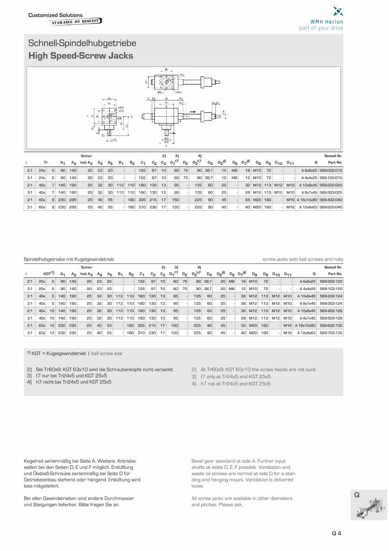
Schnell-Spindelhubgetriebe
High Speed-Screw Jacks
i Tr A1 A2
Sicher-
heit A3 A4 A5 B1 B2 C1 C2
2)
C3
3)
D1f7 D2
4)
D3h7 D4 D5
j6 D6 D7j6 D8 D9 D10 D11 Q
Bestell Nr.
Part No.
2:1 24x 5 90 140 20 23 20 - - 122 87 10 60 75 90 38,7 15 M8 18 M10 72 - - A 6x6x25 569-002-015
3:1 24x 5 90 140 20 23 20 - - 122 87 10 60 75 90 38,7 15 M8 12 M10 72 - - A 4x4x25 569-103-015
2:1 40x 7 140 190 25 32 30 113 110 180 130 13 95 - 135 60 25 - 32 M12 113 M12 M10 A 10x8x45 569-202-025
3:1 40x 7 140 190 25 32 30 113 110 180 130 13 95 - 135 60 25 - 28 M12 113 M12 M10 A 8x7x45 569-303-025
2:1 60x 9 230 295 25 40 55 - 180 305 215 17 150 - 225 90 45 - 55 M20 180 - M16 A 16x10x80 569-402-040
3:1 60x 9 230 295 25 40 55 - 180 310 230 17 120 - 225 90 45 - 40 M20 180 - M16 A 12x8x63 569-503-040
i KGT1) A1 A2
Sicher-
heit A3 A4 A5 B1 B2 C1 C2
2)
C3
3)
D1f7 D2
4)
D3h7 D4 D5
j6 D6 D7j6 D8 D9 D10 D11 Q
Bestell Nr.
Part No.
2:1 25x 5 90 140 20 23 25 - - 122 87 10 60 75 90 38,7 20 M8 18 M10 72 - - A 6x6x25 569-002-120
3:1 25x 5 90 140 20 23 25 - - 122 87 10 60 75 90 38,7 20 M8 12 M10 72 - - A 4x4x25 569-103-120
2:1 40x 5 140 190 25 32 30 113 110 180 130 13 95 - 135 60 25 - 32 M12 113 M12 M10 A 10x8x45 569-202-124
3:1 40x 5 140 190 25 32 30 113 110 180 130 13 95 - 135 60 25 - 28 M12 113 M12 M10 A 8x7x45 569-303-124
2:1 40x 10 140 190 25 32 30 113 110 180 130 13 95 - 135 60 25 - 32 M12 113 M12 M10 A 10x8x45 569-402-126
3:1 40x 10 140 190 25 32 30 113 110 180 130 13 95 - 135 60 25 - 28 M12 113 M12 M10 A 8x7x45 569-503-126
2:1 63x 10 230 295 25 40 55 - 180 305 215 17 150 - 225 90 45 - 55 M20 180 - M16 A 16x10x80 569-602-135
3:1 63x 10 230 295 25 40 55 - 180 310 230 17 120 - 225 90 45 - 40 M20 180 - M16 A 12x8x63 569-703-135
1) KGT = Kugelgewindetrieb | ball screw size
2) Bei Tr60x9; KGT 63x10 sind die Schraubenköpfe nicht versenkt3) f7 nur bei Tr24x5 und KGT 25x5 4) h7 nicht bei Tr24x5 und KGT 25x5
Kegelrad serienmäßig bei Seite A. Weitere Antriebs-wellen bei den Seiten D, E und F möglich. Entlüftung und Ölablaß-Schraube serienmäßig bei Seite D für Getriebeeinbau stehend oder hängend. Entlüftung wird lose mitgeliefert.
Bei allen Gewindetrieben sind andere Durchmesser und Steigungen lieferbar. Bitte fragen Sie an.
2) At Tr60x9; KGT 63x10 the screw heads are not sunk
3) f7 only at Tr24x5 and KGT 25x5
4) h7 not at Tr24x5 and KGT 25x5
Bevel gear standard at side A. Further input shafts at sides D, E, F possible. Ventilation and waste oil screws are normal at side D for a stan-ding and hanging mount. Ventilation is delivered loose.
All screw jacks are available in other diameters and pitches. Please ask.
Spindelhubgetriebe mit Kugelgewindetrieb screw jacks with ball screws and nuts
Customized Solutionsavailable on
Request
Q 5
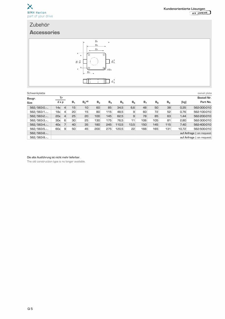
Zubehör
Accessories
Baugr. Tr Bestell Nr.
Size d x p B1 B2h6 B3 B4 B5 B6 B7 B8 B9 [kg] Part No.
562/563-0..-… 14x 4 15 10 60 85 34,5 6,6 48 50 38 0,35 562-000-010
562/563-1..-… 18x 4 20 15 80 115 48,5 9 60 72 52 0,76 562-100-010
562/563-2..-… 20x 4 25 20 100 145 62,5 9 78 85 63 1,44 562-200-010
562/563-3..-… 30x 6 30 25 130 175 76,5 11 106 105 81 2,80 562-300-010
562/563-4..-… 40x 7 40 35 180 245 110,5 13,5 150 145 115 7,40 562-400-010
562/563-5..-… 60x 9 50 45 200 275 120,5 22 166 165 131 10,72 562-500-010
562/563-8..-… auf Anfrage | on request
562/563-9..-… auf Anfrage | on request
Die alte Ausführung ist nicht mehr lieferbar.
The old construction type is no longer available.
Schwenkplatte swivel plate
Kundenorientierte Lösungen
AUF ANFRAGE
Q 6
Q
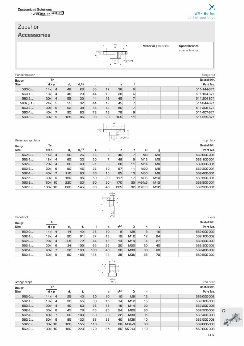
Zubehör
Accessories
Baugr. Tr Bestell Nr.
Size d x p da dnh9 L l e f Part No.
Baugr. Tr Bestell Nr.
Size d x p da dnh9 L l e f D g Part No.
Baugr. Tr Bestell Nr.
Size d x p da L I e dh8 D h v Part No.
Baugr. Tr Bestell Nr.
Size d x p da L I e dh8 D h Part No.
563-0..-… 14x 4 48 28 35 12 38 6 511-144-671
563-1..-… 18x 4 48 28 44 12 38 6 511-184-671
563-2..-… 20x 4 55 32 44 12 45 7 511-204-671
569-0/1..-… 24x 5 55 32 44 12 45 7 511-244-671
563-3..-… 30x 6 62 38 46 14 50 7 511-306-671
563-4..-… 40x 7 95 63 73 16 78 9 511-407-671
563-5..-… 60x 9 125 85 99 20 105 11 511-559-671
562-0..-… 14x 4 50 26 16 6 40 7 M8 M4 562-000-001
562-1..-… 18x 4 65 30 20 7 48 9 M12 M5 562-100-001
562-2..-… 20x 4 80 40 21 8 60 11 M14 M6 562-200-001
562-3..-… 30x 6 90 46 23 10 67 11 M20 M8 562-300-001
562-4..-… 40x 7 110 60 30 15 85 13 M30 M8 562-400-001
562-5..-… 60x 9 150 85 50 20 117 17 M36 M10 562-500-001
562-8..-… 80x 10 220 120 60 30 170 25 M64x3 M12 562-800-001
562-9..-… 100x 10 260 145 80 40 205 32 M72x3 M12 562-900-001
562-0..-… 14x 4 14 42 26 10 8 M8 8 16 562-000-002
562-1..-… 18x 4 20 61 37 13 12 M12 12 24 562-100-002
562-2..-… 20x 4 24,5 72 44 16 14 M14 14 27 562-200-002
562-3..-… 30x 6 34 105 65 25 20 M20 20 40 562-300-002
562-4..-… 40x 7 52 160 100 40 30 M30 30 60 562-400-002
562-5..-… 60x 9 60 188 116 44 35 M36 36 70 562-500-002
562-0..-… 14x 4 25 40 20 10 10 M8 12 562-000-008
562-1..-… 18x 4 30 55 30 15 14 M12 15 562-100-008
562-2..-… 20x 4 40 63 36 18 16 M14 20 562-200-008
562-3..-… 30x 6 45 78 45 25 24 M20 30 562-300-008
562-4..-… 40x 7 60 100 60 30 32 M30 35 562-400-008
562-5..-… 60x 9 85 130 66 33 40 M36 40 562-500-008
562-8..-… 80x 10 120 155 110 50 60 M64x3 80 562-800-008
562-9..-… 100x 10 160 220 170 85 80 M72x3 110 562-900-008
Flanschmutter fl ange nut
Befestigungsplatte top plate
Gabelkopf clevis
Stangenkopf rod head
Customized Solutionsavailable on
Request
Material | material Spezialbronze
special bronze
Q 7
Zubehör
Accessories
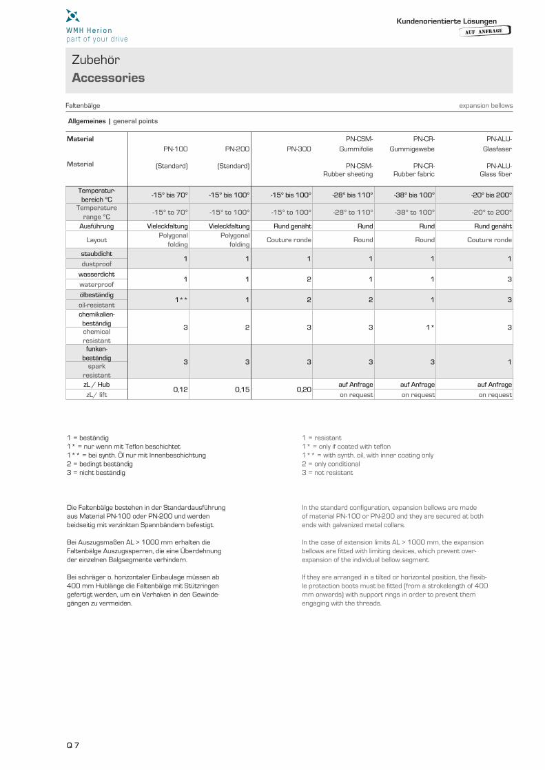
Allgemeines | general points
Material PN-CSM- PN-CR- PN-ALU-
PN-100 PN-200 PN-300 Gummifolie Gummigewebe Glasfaser
Material (Standard) (Standard) PN-CSM- PN-CR- PN-ALU-Rubber sheeting Rubber fabric Glass fiber
Temperatur-bereich °C
-15° bis 70° -15° bis 100° -15° bis 100° -28° bis 110° -38° bis 100° -20° bis 200°
Temperaturerange °C
-15° to 70° -15° to 100° -15° to 100° -28° to 110° -38° to 100° -20° to 200°
Ausführung Vieleckfaltung Vieleckfaltung Rund genäht Rund Rund Rund genäht
LayoutPolygonal
foldingPolygonal
foldingCouture ronde Round Round Couture ronde
staubdicht1 1 1 1 1 1
dustproof
wasserdicht1 1 2 1 1 3
waterproof
ölbeständig1** 1 2 2 1 3
oil-resistantchemikalien-beständig
3 2 3 3 1* 3chemicalresistantfunken-
beständig3 3 3 3 3 1
sparkresistantzL / Hub
0,12 0,15 0,20auf Anfrage auf Anfrage auf Anfrage
zL/ lift on request on request on request
Faltenbälge expansion bellows
1 = beständig 1* = nur wenn mit Teflon beschichtet 1** = bei synth. Öl nur mit Innenbeschichtung 2 = bedingt beständig 3 = nicht beständig
Die Faltenbälge bestehen in der Standardausführung aus Material PN-100 oder PN-200 und werden beidseitig mit verzinkten Spannbändern befestigt. Bei Auszugsmaßen AL > 1000 mm erhalten die Faltenbälge Auszugssperren, die eine Überdehnung der einzelnen Balgsegmente verhindern. Bei schräger o. horizontaler Einbaulage müssen ab 400 mm Hublänge die Faltenbälge mit Stützringen gefertigt werden, um ein Verhaken in den Gewinde- gängen zu vermeiden.
1 = resistant 1* = only if coated with teflon 1** = with synth. oil, with inner coating only 2 = only conditional 3 = not resistant
In the standard configuration, expansion bellows are made of material PN-100 or PN-200 and they are secured at both ends with galvanized metal collars.
In the case of extension limits AL > 1000 mm, the expansion bellows are fitted with limiting devices, which prevent over-expansion of the individual bellow segment. If they are arranged in a tilted or horizontal position, the flexib-le protection boots must be fitted (from a strokelength of 400 mm onwards) with support rings in order to prevent them engaging with the threads.
Kundenorientierte Lösungen
AUF ANFRAGE
Q 8
Q
Zubehör
Accessories
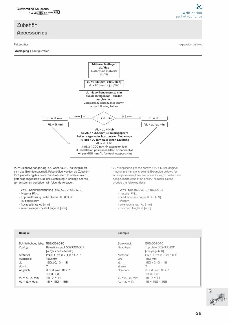
Auslegung | confi guration
Faltenbälge expansion bellows
Beispiel Example
Spindelhubgetriebe: 562-004-010Kopftyp: Befestigungspl. 562-000-001 (vergleiche Seite Q 6)Material: PN-100 => zL/Hub = 0,12Hublänge: 150 mmzL: 150 x 0,12 = 18zL min: 7Abgleich: zL > zL min: 18 > 7 => zL = zLVL = zL - zL min: 18 - 7 = 11 AL = zL + Hub: 18 + 150 = 168
VL = Spindelverlängerung, d.h. wenn VL > 0, so vergrößert sich das Grundeinbaumaß. Faltenbälge werden als Zubehör für Spindelhubgetriebe nach individuellem Kundenwunsch gefertigt angeboten. Um Ihre Bestellung / Anfrage bearbei-ten zu können, benötigen wir folgende Angaben: - WMH-Serienbezeichnung (562-X..-… / 563-X..-…) - Material PN-… - Kopfausführung (siehe Seiten Q 6 & Q 9) - Hublänge (mm) - Auszugslänge AL (mm) - zusammengedrückte Länge zL (mm)
Screw jack: 562-004-010Head type: Top plate 562-000-001 (see page Q 6)Material: PN-100 => zL/ lift = 0,12Lift: 150 mm zL: 150 x 0,12 = 18zL min: 7 Compare: zL > zL min: 18 > 7 => zL = zL VL = zL - zL min: 18 - 7 = 11 AL = zL + lift: 18 + 150 = 168
VL = lengthening of the screw; if VL > 0, the original mounting dimensions extend. Expansion bellows for screw jacks are offered as accessories, to customers design. In the case of an order/ request, please provide the following data: - WMH type (562-X..-… / 563-X..-…) - material PN-… - head type (see pages Q 6 & Q 9) - lift (mm) - extension length AL (mm) - minimum length zL (mm)
Material festlegenzL/Hub
Determine materialzL/lift
zL mit vorhandenem zL minaus nachfolgenden Tabellen
vergleichenCompare zL with zL min shown
in the following tables
zL = Hub (mm) x (zL/Hub)zL = lift (mm) x (zL/lift)
ja | yesnein | nozL = zL
VL = zL - zL min
zL = zL min
VL = 0 mm
AL = zL + Hubbei AL ≥ 1000 mm Auszugsperre
bei schräger oder horizontaler Einbaulage pro 400 mm AL je einen Stützring
AL = zL + liftif AL ≥ 1000 mm extension lock
if installation position is tilted or horizontal per 400 mm AL for each support ring
zL > zL min
Customized Solutionsavailable on
Request
Q 9
Zubehör
Accessories
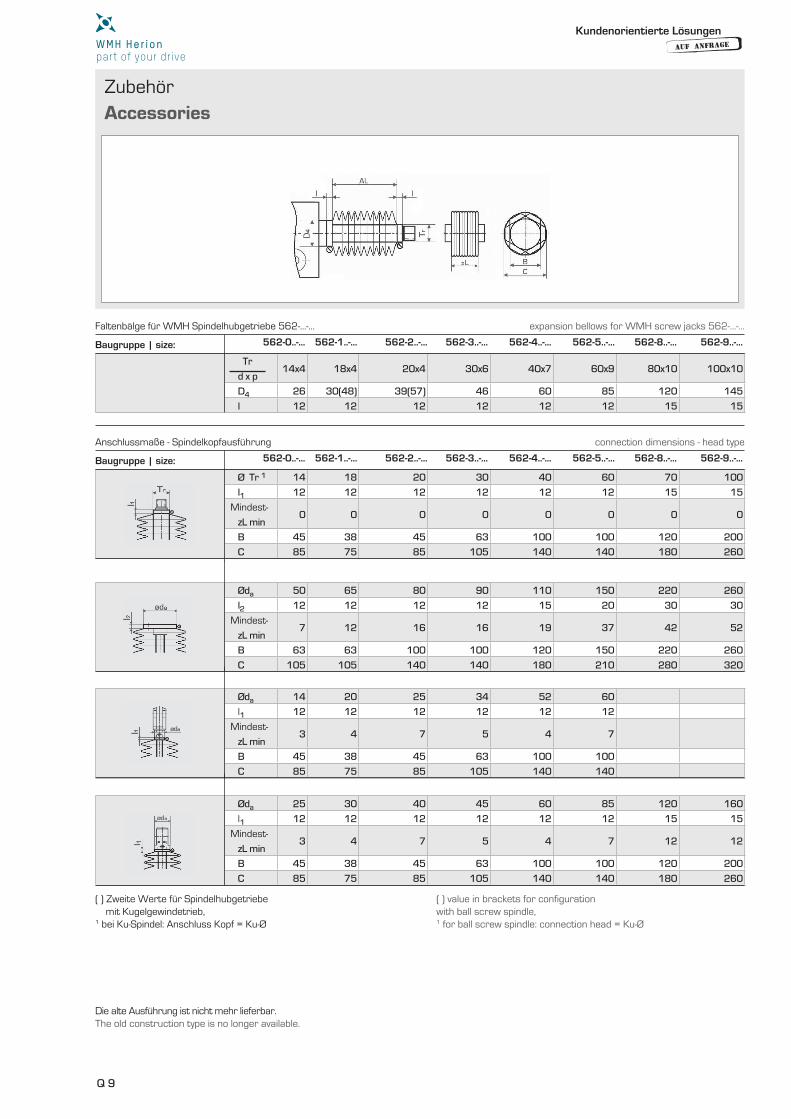
Baugruppe | size: 562-0..-… 562-1..-… 562-2..-… 562-3..-… 562-4..-… 562-5..-… 562-8..-… 562-9..-…
Baugruppe | size: 562-0..-… 562-1..-… 562-2..-… 562-3..-… 562-4..-… 562-5..-… 562-8..-… 562-9..-…
Tr 14x4 18x4 20x4 30x6 40x7 60x9 80x10 100x10
d x p
D4 26 30(48) 39(57) 46 60 85 120 145
l 12 12 12 12 12 12 15 15
Ø Tr 1 14 18 20 30 40 60 70 100
l1 12 12 12 12 12 12 15 15
Mindest-0 0 0 0 0 0 0 0
zL min
B 45 38 45 63 100 100 120 200
C 85 75 85 105 140 140 180 260
Øda 50 65 80 90 110 150 220 260
l2 12 12 12 12 15 20 30 30
Mindest-7 12 16 16 19 37 42 52
zL min
B 63 63 100 100 120 150 220 260
C 105 105 140 140 180 210 280 320
Øda 14 20 25 34 52 60
l1 12 12 12 12 12 12
Mindest-3 4 7 5 4 7
zL min
B 45 38 45 63 100 100
C 85 75 85 105 140 140
Øda 25 30 40 45 60 85 120 160
l1 12 12 12 12 12 12 15 15
Mindest-3 4 7 5 4 7 12 12
zL min
B 45 38 45 63 100 100 120 200
C 85 75 85 105 140 140 180 260
Die alte Ausführung ist nicht mehr lieferbar.The old construction type is no longer available.
( ) Zweite Werte für Spindelhubgetriebe mit Kugelgewindetrieb, 1 bei Ku-Spindel: Anschluss Kopf = Ku-Ø
( ) value in brackets for confi guration with ball screw spindle, 1 for ball screw spindle: connection head = Ku-Ø
Faltenbälge für WMH Spindelhubgetriebe 562-…-… expansion bellows for WMH screw jacks 562-…-…
Anschlussmaße - Spindelkopfausführung connection dimensions - head type
Kundenorientierte Lösungen
AUF ANFRAGE
Q 10
Q
Zubehör
Accessories
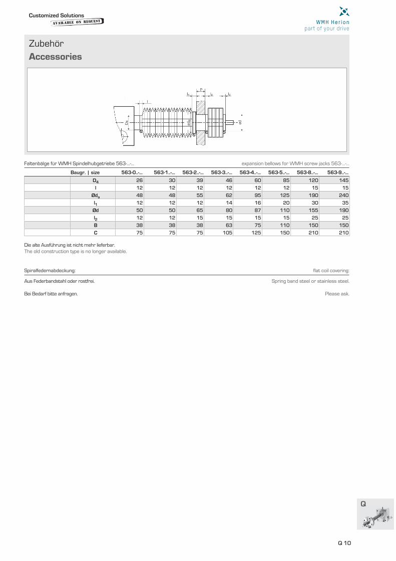
Baugr. | size 563-0..-… 563-1..-… 563-2..-… 563-3..-… 563-4..-… 563-5..-… 563-8..-… 563-9..-…
D4 26 30 39 46 60 85 120 145
l 12 12 12 12 12 12 15 15
Øda 48 48 55 62 95 125 190 240
l1 12 12 12 14 16 20 30 35
Ød 50 50 65 80 87 110 155 190
l2 12 12 15 15 15 15 25 25
B 38 38 38 63 75 110 150 150
C 75 75 75 105 125 150 210 210
Die alte Ausführung ist nicht mehr lieferbar.The old construction type is no longer available.
Aus Federbandstahl oder rostfrei. Bei Bedarf bitte anfragen.
Spring band steel or stainless steel. Please ask.
Faltenbälge für WMH Spindelhubgetriebe 563-…-… expansion bellows for WMH screw jacks 563-…-…
Spiralfedernabdeckung: fl at coil covering:
Customized Solutionsavailable on
Request
Q 11
Zubehör
Accessories
Baugr. Tr Bestell Nr.
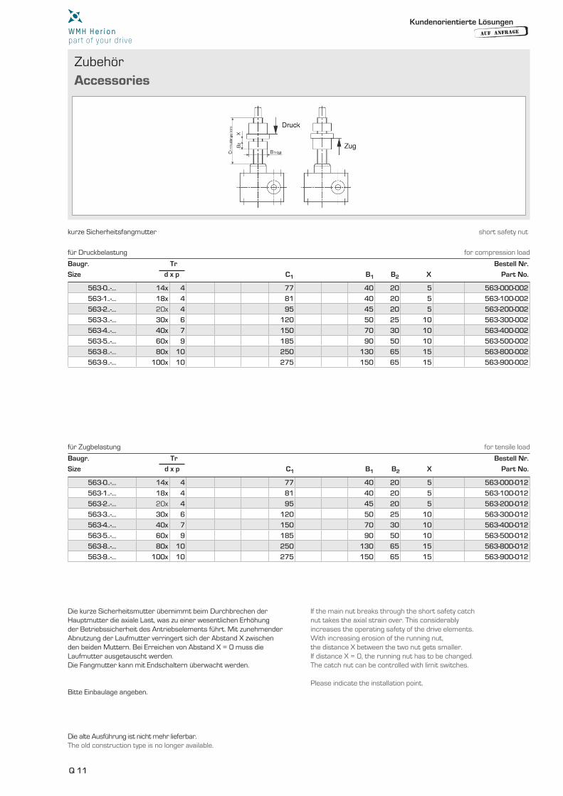
Size d x p C1 B1 B2 X Part No.
Baugr. Tr Bestell Nr.
Size d x p C1 B1 B2 X Part No.
563-0..-… 14x 4 77 40 20 5 563-000-002
563-1..-… 18x 4 81 40 20 5 563-100-002
563-2..-… 20x 4 95 45 20 5 563-200-002
563-3..-… 30x 6 120 50 25 10 563-300-002
563-4..-… 40x 7 150 70 30 10 563-400-002
563-5..-… 60x 9 185 90 50 10 563-500-002
563-8..-… 80x 10 250 130 65 15 563-800-002
563-9..-… 100x 10 275 150 65 15 563-900-002
563-0..-… 14x 4 77 40 20 5 563-000-012
563-1..-… 18x 4 81 40 20 5 563-100-012
563-2..-… 20x 4 95 45 20 5 563-200-012
563-3..-… 30x 6 120 50 25 10 563-300-012
563-4..-… 40x 7 150 70 30 10 563-400-012
563-5..-… 60x 9 185 90 50 10 563-500-012
563-8..-… 80x 10 250 130 65 15 563-800-012
563-9..-… 100x 10 275 150 65 15 563-900-012
kurze Sicherheitsfangmutter short safety nut
Die alte Ausführung ist nicht mehr lieferbar.The old construction type is no longer available.
Die kurze Sicherheitsmutter übernimmt beim Durchbrechen der Hauptmutter die axiale Last, was zu einer wesentlichen Erhöhung der Betriebssicherheit des Antriebselements führt. Mit zunehmender Abnutzung der Laufmutter verringert sich der Abstand X zwischen den beiden Muttern. Bei Erreichen von Abstand X = 0 muss die Laufmutter ausgetauscht werden. Die Fangmutter kann mit Endschaltern überwacht werden. Bitte Einbaulage angeben.
If the main nut breaks through the short safety catch nut takes the axial strain over. This considerably increases the operating safety of the drive elements. With increasing erosion of the running nut, the distance X between the two nut gets smaller. If distance X = 0, the running nut has to be changed. The catch nut can be controlled with limit switches. Please indicate the installation point.
für Druckbelastung for compression load
für Zugbelastung for tensile load
Kundenorientierte Lösungen
AUF ANFRAGE
Q 12
Q
Zubehör
Accessories
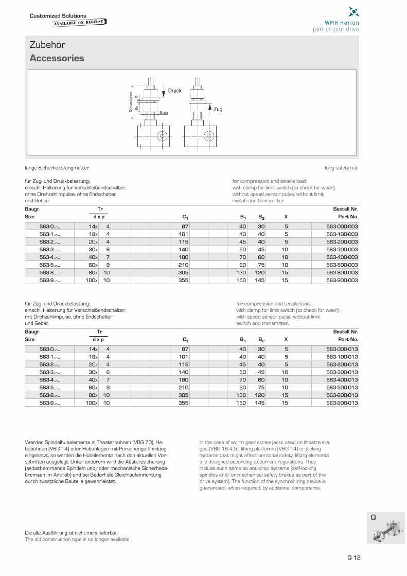
Baugr. Tr Bestell Nr.
Size d x p C1 B1 B2 X Part No.
Baugr. Tr Bestell Nr.
Size d x p C1 B1 B2 X Part No.
563-0..-… 14x 4 87 40 30 5 563-000-003
563-1..-… 18x 4 101 40 40 5 563-100-003
563-2..-… 20x 4 115 45 40 5 563-200-003
563-3..-… 30x 6 140 50 45 10 563-300-003
563-4..-… 40x 7 180 70 60 10 563-400-003
563-5..-… 60x 9 210 90 75 10 563-500-003
563-8..-… 80x 10 305 130 120 15 563-800-003
563-9..-… 100x 10 355 150 145 15 563-900-003
563-0..-… 14x 4 87 40 30 5 563-000-013
563-1..-… 18x 4 101 40 40 5 563-100-013
563-2..-… 20x 4 115 45 40 5 563-200-013
563-3..-… 30x 6 140 50 45 10 563-300-013
563-4..-… 40x 7 180 70 60 10 563-400-013
563-5..-… 60x 9 210 90 75 10 563-500-013
563-8..-… 80x 10 305 130 120 15 563-800-013
563-9..-… 100x 10 355 150 145 15 563-900-013
for compression and tensile load;with clamp for limit switch (to check for wear);without speed sensor pulse, without limit switch and transmitter.
for compression and tensile load;with clamp for limit switch (to check for wear);with speed sensor pulse, without limit switch and transmitter.
für Zug- und Druckbelastung;einschl. Halterung für Verschleißendschalter; ohne Drehzahlimpulse, ohne Endschalter und Geber.
für Zug- und Druckbelastung;einschl. Halterung für Verschleißendschalter; mit Drehzahlimpulse, ohne Endschalter und Geber.
lange Sicherheitsfangmutter long safety nut
Die alte Ausführung ist nicht mehr lieferbar.The old construction type is no longer available.
Werden Spindelhubelemente in Theaterbühnen (VBG 70), He-bebühnen (VBG 14) oder Hubanlagen mit Personengefährdung eingesetzt, so werden die Hubelemente nach den aktuellen Vor-schriften ausgelegt. Unter anderem wird die Absturzsicherung (selbsthemmende Spindeln und/oder mechanische Sicherheits-bremsen im Antrieb) und bei Bedarf die Gleichlaufeinrichtung durch zusätzliche Bauteile gewährleistet.
In the case of worm gear screw jacks used on theatre sta- ges (VBG 16.4.5), lifting platforms (VBG 14) or jacking systems that might affect personal safety, lifting elements are designed according to current regulations. They include such items as anti-drop systems (self-locking spindles and/or mechanical safety brakes as part of the drive system). The function of the synchronizing device is guaranteed, when required, by additional components.
Customized Solutionsavailable on
Request
Q 13
Zubehör
Accessories
Baugr. Bestell Nr.
Size A1 A2 A3 A4 A5 A6 A7 A8 A9 A10 [kg] Part No.
Bestell Nr.
B1 B2 B3 B4 B5 B6 C1 C2 Part No.
290-005-057 150 185 20 52 82 22 15 30 50 92 2,0 290-006-057
290-005-088 170 205 20 60 85 25 15 40 60 115 2,9 290-006-088
290-005-100 170 205 20 60 90 26 15 45 60 112 2,8 290-006-100
290-005-125 230 275 23 80 110 30 18 60 80 148 6,1 290-006-125
290-005-155 260 315 27 90 120 32 22 70 95 175 9,3 290-006-155
290-005-205 350 410 32 120 175 45 26 100 125 239 18,5 290-006-205
80 24 10 16 14 29 6 M3 562-100-009
125 28 14 18 16 36 9 M4 562-200-009
160 32 16 20 18 40 9 M4 562-300-009
225 42 20 26 24 48 9 M4 562-400-009
280 50 25 30 26 53 10 M6 562-500-009
400 65 30 38 32 63 10 M6 562-800-009
Handrad handwheel
Die alte Ausführung ist nicht mehr lieferbar.The old construction type is no longer available.
Die Handräder werden zum Verstellen und Feinjustieren der Spindelhubgetriebe von Hand eingesetzt. Die Handräder sind als Speichenräder aus Aluminiumguß ausgeführt. Der Handgriff ist drehbar.
Die Stehlager sind zur Unterstützung von langen Gelenkwellen bei hohen Drehzahlen. Je nach Länge und Drehzahl der Gelenkwelle werden ein oder mehrere Stehlager hintereinander eingebaut. Die Stehlager mit Pendelkugellagern sind wartungsfrei.
The handwheels are used to move and adjust the screw jacks by hand. The handwheels are let in spokes made of cast aluminium. The crank handle is rotable.
The pedestal bearings are useful to support long cardan shafts at high speed. It depends on length and speed of the cardan shaft if one or more bea- rings are mounted serial. The pedestal bearings with self-aligning ball bearings are maintenance-free.
Stehlager pedestal bearing
Paßfedernut nach DIN 6885 keyway acc. DIN 6885
Kundenorientierte Lösungen
AUF ANFRAGE
Q 14
Q
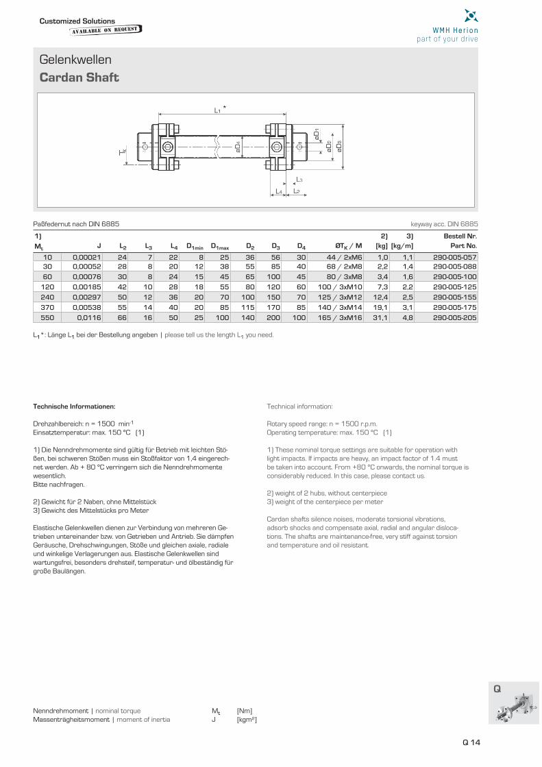
Gelenkwellen
Cardan Shaft
1) 2) 3) Bestell Nr.
Mt J L2 L3 L4 D1min D1max D2 D3 D4 ØTK / M [kg] [kg/m] Part No.
10 0,00021 24 7 22 8 25 36 56 30 44 / 2xM6 1,0 1,1 290-005-05730 0,00052 28 8 20 12 38 55 85 40 68 / 2xM8 2,2 1,4 290-005-088
60 0,00076 30 8 24 15 45 65 100 45 80 / 3xM8 3,4 1,6 290-005-100
120 0,00185 42 10 28 18 55 80 120 60 100 / 3xM10 7,3 2,2 290-005-125
240 0,00297 50 12 36 20 70 100 150 70 125 / 3xM12 12,4 2,5 290-005-155
370 0,00538 55 14 40 20 85 115 170 85 140 / 3xM14 19,1 3,1 290-005-175
550 0,0116 66 16 50 25 100 140 200 100 165 / 3xM16 31,1 4,8 290-005-205
L1*: Länge L1 bei der Bestellung angeben | please tell us the length L1 you need.
Nenndrehmoment | nominal torque Mt [Nm]Massenträgheitsmoment | moment of inertia J [kgm²]
Technische Informationen: Drehzahlbereich: n = 1500 min-1 Einsatztemperatur: max. 150 °C (1) 1) Die Nenndrehmomente sind gültig für Betrieb mit leichten Stö-ßen, bei schweren Stößen muss ein Stoßfaktor von 1,4 eingerech-net werden. Ab + 80 °C verringern sich die Nenndrehmomente wesentlich. Bitte nachfragen. 2) Gewicht für 2 Naben, ohne Mittelstück 3) Gewicht des Mittelstücks pro Meter Elastische Gelenkwellen dienen zur Verbindung von mehreren Ge-trieben untereinander bzw. von Getrieben und Antrieb. Sie dämpfen Geräusche, Drehschwingungen, Stöße und gleichen axiale, radiale und winkelige Verlagerungen aus. Elastische Gelenkwellen sind wartungsfrei, besonders drehsteif, temperatur- und ölbeständig für große Baulängen.
Technical information: Rotary speed range: n = 1500 r.p.m. Operating temperature: max. 150 °C (1) 1) These nominal torque settings are suitable for operation with light impacts. If impacts are heavy, an impact factor of 1.4 mustbe taken into account. From +80 °C onwards, the nominal torque is considerably reduced. In this case, please contact us. 2) weight of 2 hubs, without centerpiece 3) weight of the centerpiece per meter Cardan shafts silence noises, moderate torsional vibrations, adsorb shocks and compensate axial, radial and angular disloca-tions. The shafts are maintenance-free, very stiff against torsion and temperature and oil resistant.
Paßfedernut nach DIN 6885 keyway acc. DIN 6885
Customized Solutionsavailable on
Request
Q 15
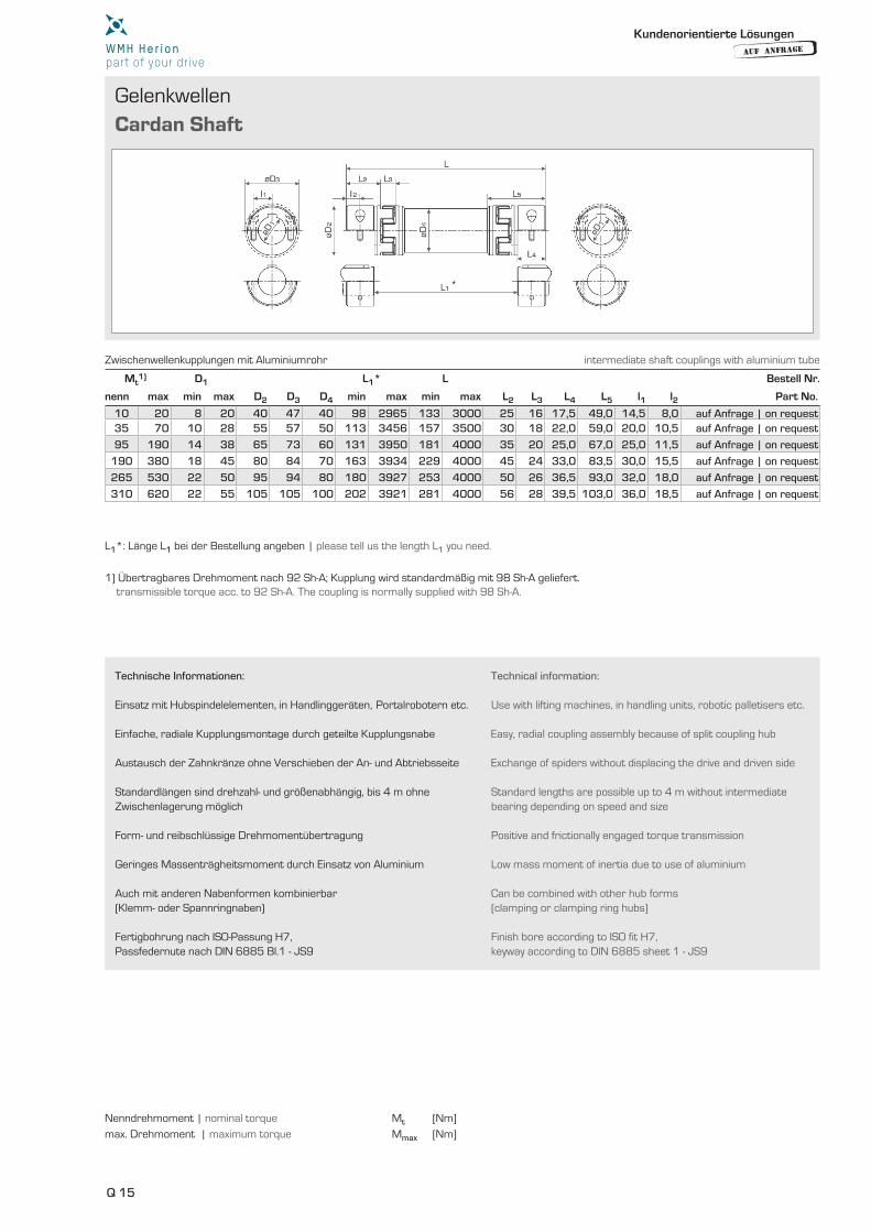
Gelenkwellen
Cardan Shaft
Mt1) D1 L1* L Bestell Nr.
nenn max min max D2 D3 D4 min max min max L2 L3 L4 L5 l1 l2 Part No.
10 20 8 20 40 47 40 98 2965 133 3000 25 16 17,5 49,0 14,5 8,0 auf Anfrage | on request35 70 10 28 55 57 50 113 3456 157 3500 30 18 22,0 59,0 20,0 10,5 auf Anfrage | on request
95 190 14 38 65 73 60 131 3950 181 4000 35 20 25,0 67,0 25,0 11,5 auf Anfrage | on request
190 380 18 45 80 84 70 163 3934 229 4000 45 24 33,0 83,5 30,0 15,5 auf Anfrage | on request
265 530 22 50 95 94 80 180 3927 253 4000 50 26 36,5 93,0 32,0 18,0 auf Anfrage | on request
310 620 22 55 105 105 100 202 3921 281 4000 56 28 39,5 103,0 36,0 18,5 auf Anfrage | on request
L1*: Länge L1 bei der Bestellung angeben | please tell us the length L1 you need.
1) Übertragbares Drehmoment nach 92 Sh-A; Kupplung wird standardmäßig mit 98 Sh-A geliefert. transmissible torque acc. to 92 Sh-A. The coupling is normally supplied with 98 Sh-A.
Nenndrehmoment | nominal torque Mt [Nm]
max. Drehmoment | maximum torque Mmax [Nm]
Zwischenwellenkupplungen mit Aluminiumrohr intermediate shaft couplings with aluminium tube
Kundenorientierte Lösungen
AUF ANFRAGE
Technische Informationen: Einsatz mit Hubspindelelementen, in Handlinggeräten, Portalrobotern etc. Einfache, radiale Kupplungsmontage durch geteilte Kupplungsnabe
Austausch der Zahnkränze ohne Verschieben der An- und Abtriebsseite
Standardlängen sind drehzahl- und größenabhängig, bis 4 m ohne Zwischenlagerung möglich
Form- und reibschlüssige Drehmomentübertragung
Geringes Massenträgheitsmoment durch Einsatz von Aluminium
Auch mit anderen Nabenformen kombinierbar (Klemm- oder Spannringnaben)
Fertigbohrung nach ISO-Passung H7, Passfedernute nach DIN 6885 Bl.1 - JS9
Technical information: Use with lifting machines, in handling units, robotic palletisers etc.
Easy, radial coupling assembly because of split coupling hub
Exchange of spiders without displacing the drive and driven side Standard lengths are possible up to 4 m without intermediate bearing depending on speed and size
Positive and frictionally engaged torque transmission
Low mass moment of inertia due to use of aluminium
Can be combined with other hub forms (clamping or clamping ring hubs)
Finish bore according to ISO fit H7, keyway according to DIN 6885 sheet 1 - JS9
Q 16
Q
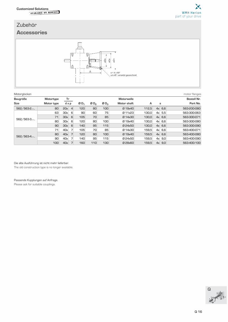
Zubehör
Accessories
Baugröße Motortype Tr Motorwelle Bestell Nr.
Size Motor type d x p Ø D1 Ø D2 Ø D3 Motor shaft A s Part No.
562/563-2..-… 80 20x 4 120 80 100 Ø 19x40 112,5 4x 6,6 563-200-080
562/563-3..-…
63 30x 6 90 60 75 Ø 11x23 130,0 4x 5,5 563-300-063
71 30x 6 105 70 85 Ø 14x30 130,0 4x 6,6 563-300-071
80 30x 6 120 80 100 Ø 19x40 130,0 4x 6,6 563-300-080
90 30x 6 140 95 115 Ø 24x50 130,0 4x 6,6 563-300-090
562/563-4..-…
71 40x 7 105 70 85 Ø 14x30 159,5 4x 6,6 563-400-071
80 40x 7 120 80 100 Ø 19x40 159,5 4x 6,6 563-400-080
90 40x 7 140 95 115 Ø 24x50 159,5 4x 9,0 563-400-090
100 40x 7 160 110 130 Ø 28x60 159,5 4x 9,0 563-400-100
Die alte Ausführung ist nicht mehr lieferbar.
The old construction type is no longer available.
Passende Kupplungen auf Anfrage.
Please ask for suitable couplings.
Motorglocken motor fl anges
Customized Solutionsavailable on
Request
Q 17
Zubehör
Accessories
Besonders geeignet für Endlagenabschaltung | specially suitable for switching off at stop position.
Bestell Nr.
Part No.
563-999-002
Die alte Ausführung ist nicht mehr lieferbar.The old construction type is no longer available.
Bauform: kunststoffgekapseltUmgebungstemperatur: - 25 °C bis 70 °CSchutzart: IP 66Leitungseinführung: ISO, M16 x 1,5Kurzschlussschutz: 10AHilfschaltereinsätze: Einkreiswechsler Ö/S mit Sprungfunktion und Zwangsöffnung des Öffners
mit Fußausführung, Bauform B3 mit Flansch-Ausführung Bremsmotoren Sondermotoren Bitte anfragen.
Design: encased in plasticAmbient temperature: -25 °C to +70 °CProtection rating: IP 66Line entrance: PG 11Short-circuit protection: 10AAuxiliary switch inserts: single-circuit change- over contact open/ closed with jumper function and forced opening of break contact
With foot construction, structural shape B3 With flange construction Braking motors Special motors Please ask.
Mechanischer Endschalter mechanical limit switch
Drehstromnormmotoren three phase standard motor
Kundenorientierte Lösungen
AUF ANFRAGE
Q 18
Q
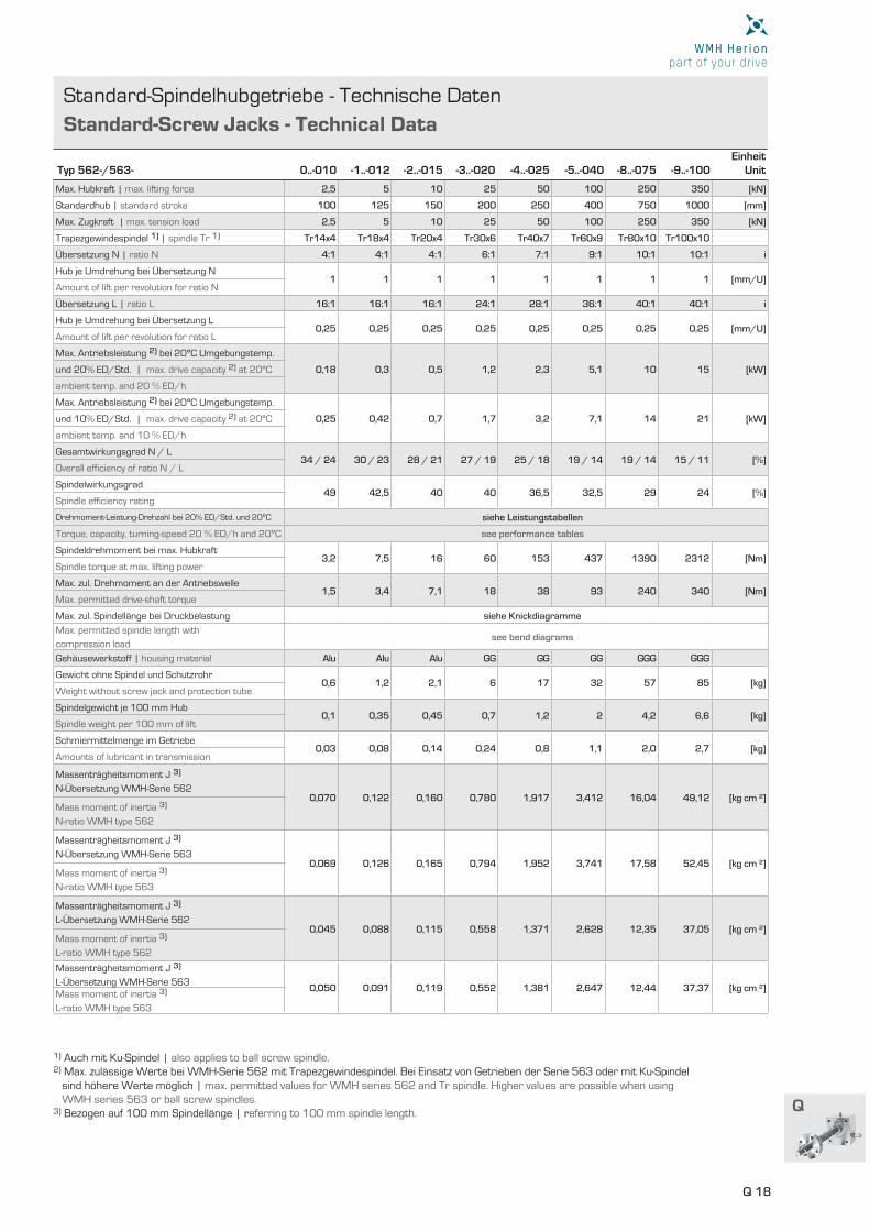
Standard-Spindelhubgetriebe - Technische Daten
Standard-Screw Jacks - Technical Data
Typ 562-/563- 0..-010 -1..-012 -2..-015 -3..-020 -4..-025 -5..-040 -8..-075 -9..-100Einheit
Unit
Max. Hubkraft | max. lifting force 2,5 5 10 25 50 100 250 350 [kN]
Standardhub | standard stroke 100 125 150 200 250 400 750 1000 [mm]
Max. Zugkraft | max. tension load 2,5 5 10 25 50 100 250 350 [kN]
Trapezgewindespindel 1) | spindle Tr 1) Tr14x4 Tr18x4 Tr20x4 Tr30x6 Tr40x7 Tr60x9 Tr80x10 Tr100x10
Übersetzung N | ratio N 4:1 4:1 4:1 6:1 7:1 9:1 10:1 10:1 i
Hub je Umdrehung bei Übersetzung N 1 1 1 1 1 1 1 1 [mm/U]
Amount of lift per revolution for ratio N
Übersetzung L | ratio L 16:1 16:1 16:1 24:1 28:1 36:1 40:1 40:1 i
Hub je Umdrehung bei Übersetzung L 0,25 0,25 0,25 0,25 0,25 0,25 0,25 0,25 [mm/U]
Amount of lift per revolution for ratio L
Max. Antriebsleistung 2) bei 20°C Umgebungstemp.
0,18 0,3 0,5 1,2 2,3 5,1 10 15 [kW]und 20% ED/Std. | max. drive capacity 2) at 20°C
ambient temp. and 20 % ED/h
Max. Antriebsleistung 2) bei 20°C Umgebungstemp.
0,25 0,42 0,7 1,7 3,2 7,1 14 21 [kW]und 10% ED/Std. | max. drive capacity 2) at 20°C
ambient temp. and 10 % ED/h
Gesamtwirkungsgrad N / L34 / 24 30 / 23 28 / 21 27 / 19 25 / 18 19 / 14 19 / 14 15 / 11 [%]
Overall effi ciency of ratio N / L
Spindelwirkungsgrad 49 42,5 40 40 36,5 32,5 29 24 [%]
Spindle effi ciency rating
Drehmoment-Leistung-Drehzahl bei 20% ED/Std. und 20°C siehe Leistungstabellen
Torque, capacity, turning-speed 20 % ED/h and 20°C see performance tables
Spindeldrehmoment bei max. Hubkraft3,2 7,5 16 60 153 437 1390 2312 [Nm]
Spindle torque at max. lifting power
Max. zul. Drehmoment an der Antriebswelle1,5 3,4 7,1 18 38 93 240 340 [Nm]
Max. permitted drive-shaft torque
Max. zul. Spindellänge bei Druckbelastung siehe Knickdiagramme
Max. permitted spindle length with
compression loadsee bend diagrams
Gehäusewerkstoff | housing material Alu Alu Alu GG GG GG GGG GGG
Gewicht ohne Spindel und Schutzrohr0,6 1,2 2,1 6 17 32 57 85 [kg]
Weight without screw jack and protection tube
Spindelgewicht je 100 mm Hub 0,1 0,35 0,45 0,7 1,2 2 4,2 6,6 [kg]
Spindle weight per 100 mm of lift
Schmiermittelmenge im Getriebe 0,03 0,08 0,14 0,24 0,8 1,1 2,0 2,7 [kg]
Amounts of lubricant in transmission
Massenträgheitsmoment J 3)
N-Übersetzung WMH-Serie 5620,070 0,122 0,160 0,780 1,917 3,412 16,04 49,12 [kg cm ²]
Mass moment of inertia 3)
N-ratio WMH type 562
Massenträgheitsmoment J 3)
N-Übersetzung WMH-Serie 5630,069 0,126 0,165 0,794 1,952 3,741 17,58 52,45 [kg cm ²]
Mass moment of inertia 3)
N-ratio WMH type 563
Massenträgheitsmoment J 3)
L-Übersetzung WMH-Serie 5620,045 0,088 0,115 0,558 1,371 2,628 12,35 37,05 [kg cm ²]
Mass moment of inertia 3)
L-ratio WMH type 562
Massenträgheitsmoment J 3)
L-Übersetzung WMH-Serie 5630,050 0,091 0,119 0,552 1,381 2,647 12,44 37,37 [kg cm ²]
Mass moment of inertia 3)
L-ratio WMH type 563
1) Auch mit Ku-Spindel | also applies to ball screw spindle. 2) Max. zulässige Werte bei WMH-Serie 562 mit Trapezgewindespindel. Bei Einsatz von Getrieben der Serie 563 oder mit Ku-Spindel sind höhere Werte möglich | max. permitted values for WMH series 562 and Tr spindle. Higher values are possible when using WMH series 563 or ball screw spindles. 3) Bezogen auf 100 mm Spindellänge | referring to 100 mm spindle length.
Q 19
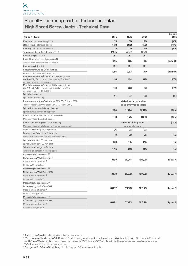
Schnell-Spindelhubgetriebe - Technische Daten
High Speed-Screw Jacks - Technical Data
Typ 567-/569- --015 -025 -040Einheit
Unit
Max. Hubkraft | max. lifting force 15 50 90 [kN]
Standardhub | standard stroke 150 250 400 [mm]
Max. Zugkraft | max. tension load 15 50 90 [kN]
Trapezgewindespindel 1) | spindle Tr 1) 24x5 40x7 60x9
Übersetzung N | ratio N 2:1 2:1 2:1
Hub je Umdrehung bei Übersetzung N 2,5 3,5 4,5 [mm/U]
Amount of lift per revolution for ratio N
Übersetzung L | ratio L 3:1 3:1 3:1
Hub je Umdrehung bei Übersetzung L 1,66 2,33 3,0 [mm/U]
Amount of lift per revolution for ratio L
Max. Antriebsleistung 2) bei 20°C Umgebungstemp.
und 20% ED/Std. | max. drive capacity 2) at 20°C
ambient temp. and 20 % ED/h
1,0 2,4 8,9 [kW]
Max. Antriebsleistung 2) bei 20°C Umgebungstemp.
und 10% ED/Std. | max. drive capacity 2) at 20°C
ambient temp. and 10 % ED/h
1,3 3,8 13 [kW]
Spindelwirkungsgrad 41 37 33 [%]
Spindle efficiency rating
Drehmoment-Leistung-Drehzahl bei 20% ED/Std. und 20°C siehe Leistungstabellen
Torque, capacity, turning-speed 20 % ED/h and 20°C see performance tables
Spindeldrehmoment bei max. Hubkraft29,4 123,4 398,5 [Nm]
Spindle torque at max. lifting power
Max. zul. Drehmoment an der Antriebswelle50 175 1600 [Nm]
Max. permitted drive-shaft torque
Max. zul. Spindellänge bei Druckbelastung siehe Knickdiagramm [mm]
Max. permitted spindle length with compression load see bend diagram
Gehäusewerkstoff | housing material GG GG GG
Gewicht ohne Spindel und Schutzrohr 9 23 85 [kg]
Weight without screw jack and protection tube
Spindelgewicht je 100 mm Hub 0,8 1,5 2,5 [kg]
Spindle weight per 100 mm of lift
Schmiermittelmenge im Getriebe 0,15 0,6 3,5 [kg]
Amounts of lubricant in transmission
Massenträgheitsmoment J 3)
1,058 22,44 181,28 [kg cm ²]N-Übersetzung WMH-Serie 567
Mass moment of inertia 3)
N-ratio WMH type 567
Massenträgheitsmoment J 3)
1,079 22,89 184,92 [kg cm ²]N-Übersetzung WMH-Serie 569
Mass moment of inertia 3)
N-ratio WMH type 569
Massenträgheitsmoment J 3)
0,667 7,248 123,79 [kg cm ²]L-Übersetzung WMH-Serie 567
Mass moment of inertia 3)
L-ratio WMH type 567
Massenträgheitsmoment J 3)
0,691 7,393 126,28 [kg cm ²]L-Übersetzung WMH-Serie 569
Mass moment of inertia 3)
L-ratio WMH type 569
1) Auch mit Ku-Spindel | also applies to ball screw spindle. 2) Max. zulässige Werte bei WMH-Serie 567 mit Trapezgewindespindel. Bei Einsatz von Getrieben der Serie 569 oder mit Ku-Spindel sind höhere Werte möglich | max. permitted values for WMH series 567 and Tr spindle. Higher values are possible when using WMH series 569 or ball screw spindles. 3) Bezogen auf 100 mm Spindellänge | referring to 100 mm spindle length.
Q 20
Q
Spindelhubgetriebe - Technische Daten
Screw Jacks - Technical Data
N L Nm kW Nm kW Nm kW Nm kW Nm kW Nm kW Nm kW Nm kW Nm kW Nm kW Nm kW Nm kW Nm kW Nm kW
N L Nm kW Nm kW Nm kW Nm kW Nm kW Nm kW Nm kW Nm kW Nm kW Nm kW Nm kW Nm kW Nm kW Nm kW
N L Nm kW Nm kW Nm kW Nm kW Nm kW Nm kW Nm kW Nm kW Nm kW Nm kW Nm kW Nm kW Nm kW Nm kW
N L Nm kW Nm kW Nm kW Nm kW Nm kW Nm kW Nm kW Nm kW Nm kW Nm kW Nm kW Nm kW Nm kW Nm kW
[1/min] (m/min) N L N L N L N L N L N L N L
[1/min] (m/min) N L N L N L N L N L N L N L
[1/min] (m/min) N L N L N L N L N L N L N L
[1/min] (m/min) N L N L N L N L N L N L N L
n Hubgeschw. F=2,5 [kN] F=2 [kN] F=1,5 [kN] F=1 [kN] F=0,75 [kN] F=0,5 [kN] F=0,25 [kN]
n Hubgeschw. F=5 [kN] F=4 [kN] F=3 [kN] F=2,5 [kN] F=2 [kN] F=1,5 [kN] F=1 [kN]
n Hubgeschw. F=10 [kN] F=8 [kN] F=6 [kN] F=4 [kN] F=3 [kN] F=2 [kN] F=1 [kN]
n Hubgeschw. F=25 [kN] F=20 [kN] F=15 [kN] F=10 [kN] F=5 [kN] F=2,5 [kN] F=1 [kN]
1500 1,50 0,375 1,2 0,18 0,4 0,1 0,9 0,15 0,3 0,1 0,7 0,1 0,2 0,1 0,5 0,1 0,2 0,1 0,4 0,1 0,1 0,1 0,2 0,1 0,1 0,1 0,1 0,1 0,0 0,1
1000 1,00 0,250 1,2 0,12 0,4 0,1 0,9 0,10 0,3 0,1 0,7 0,1 0,2 0,1 0,5 0,1 0,2 0,1 0,4 0,1 0,1 0,1 0,2 0,1 0,1 0,1 0,1 0,1 0,0 0,1
750 0,75 0,188 1,2 0,10 0,4 0,1 0,9 0,1 0,3 0,1 0,7 0,1 0,2 0,1 0,5 0,1 0,2 0,1 0,4 0,1 0,1 0,1 0,2 0,1 0,1 0,1 0,1 0,1 0,0 0,1
600 0,60 0,150 1,2 0,1 0,4 0,1 0,9 0,1 0,3 0,1 0,7 0,1 0,2 0,1 0,5 0,1 0,2 0,1 0,4 0,1 0,1 0,1 0,2 0,1 0,1 0,1 0,1 0,1 0,0 0,1
500 0,50 0,125 1,2 0,1 0,4 0,1 0,9 0,1 0,3 0,1 0,7 0,1 0,2 0,1 0,5 0,1 0,2 0,1 0,4 0,1 0,1 0,1 0,2 0,1 0,1 0,1 0,1 0,1 0,0 0,1
300 0,30 0,075 1,2 0,1 0,4 0,1 0,9 0,1 0,3 0,1 0,7 0,1 0,2 0,1 0,5 0,1 0,2 0,1 0,4 0,1 0,1 0,1 0,2 0,1 0,1 0,1 0,1 0,1 0,0 0,1
100 0,10 0,025 1,2 0,1 0,4 0,1 0,9 0,1 0,3 0,1 0,7 0,1 0,2 0,1 0,5 0,1 0,2 0,1 0,4 0,1 0,1 0,1 0,2 0,1 0,1 0,1 0,1 0,1 0,0 0,1
50 0,05 0,013 1,2 0,1 0,4 0,1 0,9 0,1 0,3 0,1 0,7 0,1 0,2 0,1 0,5 0,1 0,2 0,1 0,4 0,1 0,1 0,1 0,2 0,1 0,1 0,1 0,1 0,1 0,0 0,1
1500 1,50 0,375 2,7 0,42 0,9 0,1 2,1 0,33 0,7 0,1 1,6 0,25 0,5 0,1 1,3 0,21 0,4 0,1 1,1 0,20 0,3 0,1 0,8 0,1 0,3 0,1 0,5 0,1 0,2 0,1
1000 1,00 0,250 2,7 0,28 0,9 0,1 2,1 0,22 0,7 0,1 1,6 0,17 0,5 0,1 1,3 0,14 0,4 0,1 1,1 0,10 0,3 0,1 0,8 0,1 0,3 0,1 0,5 0,1 0,2 0,1
750 0,75 0,188 2,7 0,21 0,9 0,1 2,1 0,17 0,7 0,1 1,6 0,13 0,5 0,1 1,3 0,10 0,4 0,1 1,1 0,1 0,3 0,1 0,8 0,1 0,3 0,1 0,5 0,1 0,2 0,1
600 0,60 0,150 2,7 0,17 0,9 0,1 2,1 0,13 0,7 0,1 1,6 0,10 0,5 0,1 1,3 0,1 0,4 0,1 1,1 0,1 0,3 0,1 0,8 0,1 0,3 0,1 0,5 0,1 0,2 0,1
500 0,50 0,125 2,7 0,14 0,9 0,1 2,1 0,1 0,7 0,1 1,6 0,1 0,5 0,1 1,3 0,1 0,4 0,1 1,1 0,1 0,3 0,1 0,8 0,1 0,3 0,1 0,5 0,1 0,2 0,1
300 0,30 0,075 2,7 0,1 0,9 0,1 2,1 0,1 0,7 0,1 1,6 0,1 0,5 0,1 1,3 0,1 0,4 0,1 1,1 0,1 0,3 0,1 0,8 0,1 0,3 0,1 0,5 0,1 0,2 0,1
100 0,10 0,025 2,7 0,1 0,9 0,1 2,1 0,1 0,7 0,1 1,6 0,1 0,5 0,1 1,3 0,1 0,4 0,1 1,1 0,1 0,3 0,1 0,8 0,1 0,3 0,1 0,5 0,1 0,2 0,1
50 0,05 0,013 2,7 0,1 0,9 0,1 2,1 0,1 0,7 0,1 1,6 0,1 0,5 0,1 1,3 0,1 0,4 0,1 1,1 0,1 0,3 0,1 0,8 0,1 0,3 0,1 0,5 0,1 0,2 0,1
1500 1,50 0,375 5,7 0,89 1,9 0,30 4,5 0,71 1,5 0,24 3,4 0,54 1,1 0,18 2,3 0,36 0,8 0,1 1,7 0,27 0,6 0,1 1,1 0,20 0,4 0,1 0,6 0,1 0,2 0,1
1000 1,00 0,250 5,7 0,60 1,9 0,20 4,5 0,48 1,5 0,16 3,4 0,36 1,1 0,12 2,3 0,24 0,8 0,1 1,7 0,18 0,6 0,1 1,1 0,10 0,4 0,1 0,6 0,1 0,2 0,1
750 0,75 0,188 5,7 0,45 1,9 0,15 4,5 0,36 1,5 0,12 3,4 0,27 1,1 0,1 2,3 0,18 0,8 0,1 1,7 0,13 0,6 0,1 1,1 0,1 0,4 0,1 0,6 0,1 0,2 0,1
600 0,60 0,150 5,7 0,36 1,9 0,12 4,5 0,29 1,5 0,10 3,4 0,21 1,1 0,1 2,3 0,14 0,8 0,1 1,7 0,1 0,6 0,1 1,1 0,1 0,4 0,1 0,6 0,1 0,2 0,1
500 0,50 0,125 5,7 0,30 1,9 0,1 4,5 0,24 1,5 0,1 3,4 0,18 1,1 0,1 2,3 0,12 0,8 0,1 1,7 0,1 0,6 0,1 1,1 0,1 0,4 0,1 0,6 0,1 0,2 0,1
300 0,30 0,075 5,7 0,18 1,9 0,1 4,5 0,14 1,5 0,1 3,4 0,11 1,1 0,1 2,3 0,10 0,8 0,1 1,7 0,1 0,6 0,1 1,1 0,1 0,4 0,1 0,6 0,1 0,2 0,1
100 0,10 0,025 5,7 0,10 1,9 0,1 4,5 0,1 1,5 0,1 3,4 0,1 1,1 0,1 2,3 0,1 0,8 0,1 1,7 0,1 0,6 0,1 1,1 0,1 0,4 0,1 0,6 0,1 0,2 0,1
50 0,05 0,013 5,7 0,1 1,9 0,1 4,5 0,1 1,5 0,1 3,4 0,1 1,1 0,1 2,3 0,1 0,8 0,1 1,7 0,1 0,6 0,1 1,1 0,1 0,4 0,1 0,6 0,1 0,2 0,1
1500 1,50 0,375 14,7 2,31 5,2 0,82 11,8 1,85 4,2 0,66 8,8 1,39 3,1 0,49 5,9 0,93 2,1 0,33 2,9 0,46 1,0 0,2 1,5 0,2 0,5 0,1 0,6 0,1 0,2 0,1
1000 1,00 0,250 14,7 1,54 5,2 0,55 11,8 1,23 4,2 0,44 8,8 0,93 3,1 0,33 5,9 0,62 2,1 0,22 2,9 0,31 1,0 0,1 1,5 0,2 0,5 0,1 0,6 0,1 0,2 0,1
750 0,75 0,188 14,7 1,16 5,2 0,41 11,8 0,93 4,2 0,33 8,8 0,69 3,1 0,25 5,9 0,46 2,1 0,16 2,9 0,23 1,0 0,1 1,5 0,1 0,5 0,1 0,6 0,1 0,2 0,1
600 0,60 0,150 14,7 0,93 5,2 0,33 11,8 0,74 4,2 0,26 8,8 0,56 3,1 0,20 5,9 0,37 2,1 0,13 2,9 0,19 1,0 0,1 1,5 0,1 0,5 0,1 0,6 0,1 0,2 0,1
500 0,50 0,125 14,7 0,77 5,2 0,27 11,8 0,62 4,2 0,22 8,8 0,46 3,1 0,16 5,9 0,31 2,1 0,11 2,9 0,15 1,0 0,1 1,5 0,1 0,5 0,1 0,6 0,1 0,2 0,1
300 0,30 0,075 14,7 0,46 5,2 0,16 11,8 0,37 4,2 0,13 8,8 0,28 3,1 0,10 5,9 0,19 2,1 0,1 2,9 0,10 1,0 0,1 1,5 0,1 0,5 0,1 0,6 0,1 0,2 0,1
100 0,10 0,025 14,7 0,15 5,2 0,10 11,8 0,12 4,2 0,1 8,8 0,10 3,1 0,1 5,9 0,10 2,1 0,1 2,9 0,1 1,0 0,1 1,5 0,1 0,5 0,1 0,6 0,1 0,2 0,1
50 0,05 0,013 14,7 0,10 5,2 0,1 11,8 0,1 4,2 0,1 8,8 0,1 3,1 0,1 5,9 0,1 2,1 0,1 2,9 0,1 1,0 0,1 1,5 0,1 0,5 0,1 0,6 0,1 0,2 0,1
Drehzahl, Kraftbedarf und zulässige Hubgeschwindigkeit bei Über-setzung N und L mit eingängiger, hebender (WMH-Serie 562) Trapezgewindespindel. Alle Leistungsangaben beziehen sich auf die dynamische Hubkraft. Bei Einschaltdauer <10%/Std., oder Aus-führung mit drehender Spindel (WMH-Serie 563) können die max. zulässigen Antriebsleistungen erhöht werden.
Bitte anfragen.
Turning speed, power requirement and permitted lifting speed for ratio N and L with single-threaded, lifting (WMH type 562) trapezoi-dal spindle. All performance data are expressed in terms of dynamic lifting force. With load factors of <10%/h or confi guration rotating spindle (WMH type 563), the maximum permitted drive capacities can be increased. Please ask.
Spindel Tr 14x4 spindle Tr 14x4
Spindel Tr 18x4 spindle Tr 18x4
Spindel Tr 20x4 spindle Tr 20x4
Spindel Tr 30x6 spindle Tr 30x6
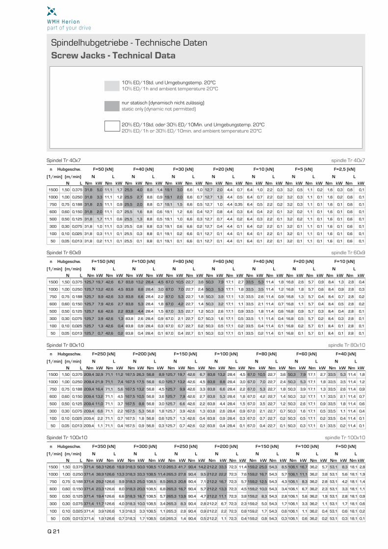
Q 21
Spindelhubgetriebe - Technische Daten
Screw Jacks - Technical Data
N L Nm kW Nm kW Nm kW Nm kW Nm kW Nm kW Nm kW Nm kW Nm kW Nm kW Nm kW Nm kW Nm kW Nm kW
N L Nm kW Nm kW Nm kW Nm kW Nm kW Nm kW Nm kW Nm kW Nm kW Nm kW Nm kW Nm kW Nm kW Nm kW
N L Nm kW Nm kW Nm kW Nm kW Nm kW Nm kW Nm kW Nm kW Nm kW Nm kW Nm kW Nm kW Nm kW Nm kW
[1/min] (m/min) N L N L N L N L N L N L N L
[1/min] (m/min) N L N L N L N L N L N L N L
[1/min] (m/min) N L N L N L N L N L N L N L
N L Nm kW Nm kW Nm kW Nm kW Nm kW Nm kW Nm kW Nm kW Nm kW Nm kW Nm kW Nm kW Nm kW Nm kW
[1/min] (m/min) N L N L N L N L N L N L N L
n Hubgeschw. F=50 [kN] F=40 [kN] F=30 [kN] F=20 [kN] F=10 [kN] F=5 [kN] F=2,5 [kN]
n Hubgeschw. F=150 [kN] F=100 [kN] F=80 [kN] F=60 [kN] F=40 [kN] F=20 [kN] F=10 [kN]
n Hubgeschw. F=250 [kN] F=200 [kN] F=150 [kN] F=100 [kN] F=80 [kN] F=60 [kN] F=40 [kN]
n Hubgeschw. F=350 [kN] F=300 [kN] F=250 [kN] F=200 [kN] F=150 [kN] F=100 [kN] F=50 [kN]
1500 1,50 0,375 31,8 5,0 11,1 1,7 25,5 4,0 8,8 1,4 19,1 3,0 6,6 1,0 12,7 2,0 4,4 0,7 6,4 1,0 2,2 0,3 3,2 0,5 1,1 0,2 1,6 0,3 0,6 0,1
1000 1,00 0,250 31,8 3,3 11,1 1,2 25,5 2,7 8,8 0,9 19,1 2,0 6,6 0,7 12,7 1,3 4,4 0,5 6,4 0,7 2,2 0,2 3,2 0,3 1,1 0,1 1,6 0,2 0,6 0,1
750 0,75 0,188 31,8 2,5 11,1 0,9 25,5 2,0 8,8 0,7 19,1 1,5 6,6 0,5 12,7 1,0 4,4 0,35 6,4 0,5 2,2 0,2 3,2 0,3 1,1 0,1 1,6 0,1 0,6 0,1
600 0,60 0,150 31,8 2,0 11,1 0,7 25,5 1,6 8,8 0,6 19,1 1,2 6,6 0,4 12,7 0,8 4,4 0,3 6,4 0,4 2,2 0,1 3,2 0,2 1,1 0,1 1,6 0,1 0,6 0,1
500 0,50 0,125 31,8 1,7 11,1 0,6 25,5 1,3 8,8 0,5 19,1 1,0 6,6 0,3 12,7 0,7 4,4 0,2 6,4 0,3 2,2 0,1 3,2 0,2 1,1 0,1 1,6 0,1 0,6 0,1
300 0,30 0,075 31,8 1,0 11,1 0,3 25,5 0,8 8,8 0,3 19,1 0,6 6,6 0,2 12,7 0,4 4,4 0,1 6,4 0,2 2,2 0,1 3,2 0,1 1,1 0,1 1,6 0,1 0,6 0,1
100 0,10 0,025 31,8 0,3 11,1 0,1 25,5 0,3 8,8 0,1 19,1 0,2 6,6 0,1 12,7 0,1 4,4 0,1 6,4 0,1 2,2 0,1 3,2 0,1 1,1 0,1 1,6 0,1 0,6 0,1
50 0,05 0,013 31,8 0,2 11,1 0,1 25,5 0,1 8,8 0,1 19,1 0,1 6,6 0,1 12,7 0,1 4,4 0,1 6,4 0,1 2,2 0,1 3,2 0,1 1,1 0,1 1,6 0,1 0,6 0,1
1500 1,50 0,375 125,7 19,7 42,6 6,7 83,8 13,2 28,4 4,5 67,0 10,5 22,7 3,6 50,3 7,9 17,1 2,7 33,5 5,3 11,4 1,8 16,8 2,6 5,7 0,9 8,4 1,3 2,8 0,4
1000 1,00 0,250 125,7 13,2 42,6 4,5 83,8 8,8 28,4 3,0 67,0 7,0 22,7 2,4 50,3 5,3 17,1 1,8 33,5 3,5 11,4 1,2 16,8 1,8 5,7 0,6 8,4 0,9 2,8 0,3
750 0,75 0,188 125,7 9,9 42,6 3,3 83,8 6,6 28,4 2,2 67,0 5,3 22,7 1,8 50,3 3,9 17,1 1,3 33,5 2,6 11,4 0,9 16,8 1,3 5,7 0,4 8,4 0,7 2,8 0,2
600 0,60 0,150 125,7 7,9 42,6 2,7 83,8 5,3 28,4 1,8 67,0 4,2 22,7 1,4 50,3 3,2 17,1 1,1 33,5 2,1 11,4 0,7 16,8 1,1 5,7 0,4 8,4 0,5 2,8 0,2
500 0,50 0,125 125,7 6,6 42,6 2,2 83,8 4,4 28,4 1,5 67,0 3,5 22,7 1,2 50,3 2,6 17,1 0,9 33,5 1,8 11,4 0,6 16,8 0,9 5,7 0,3 8,4 0,4 2,8 0,1
300 0,30 0,075 125,7 3,9 42,6 1,3 83,8 2,6 28,4 0,9 67,0 2,1 22,7 0,7 50,3 1,6 17,1 0,5 33,5 1,1 11,4 0,4 16,8 0,5 5,7 0,2 8,4 0,3 2,8 0,1
100 0,10 0,025 125,7 1,3 42,6 0,4 83,8 0,9 28,4 0,3 67,0 0,7 22,7 0,2 50,3 0,5 17,1 0,2 33,5 0,4 11,4 0,1 16,8 0,2 5,7 0,1 8,4 0,1 2,8 0,1
50 0,05 0,013 125,7 0,7 42,6 0,2 83,8 0,4 28,4 0,1 67,0 0,4 22,7 0,1 50,3 0,3 17,1 0,1 33,5 0,2 11,4 0,1 16,8 0,1 5,7 0,1 8,4 0,1 2,8 0,1
1500 1,50 0,375 209,4 32,9 71,1 11,2 167,5 26,3 56,8 8,9 125,7 19,7 42,6 6,7 83,8 13,2 28,4 4,5 67,0 10,5 22,7 3,6 50,3 7,9 17,1 2,7 33,5 5,3 11,4 1,8
1000 1,00 0,250 209,4 21,9 71,1 7,4 167,5 17,5 56,8 6,0 125,7 13,2 42,6 4,5 83,8 8,8 28,4 3,0 67,0 7,0 22,7 2,4 50,3 5,3 17,1 1,8 33,5 3,5 11,4 1,2
750 0,75 0,188 209,4 16,4 71,1 5,6 167,5 13,2 56,8 4,5 125,7 9,9 42,6 3,3 83,8 6,6 28,4 2,2 67,0 5,3 22,7 1,8 50,3 3,9 17,1 1,3 33,5 2,6 11,4 0,9
600 0,60 0,150 209,4 13,2 71,1 4,5 167,5 10,5 56,8 3,6 125,7 7,9 42,6 2,7 83,8 5,3 28,4 1,8 67,0 4,2 22,7 1,4 50,3 3,2 17,1 1,1 33,5 2,1 11,4 0,7
500 0,50 0,125 209,4 11,0 71,1 3,7 167,5 8,8 56,8 3,0 125,7 6,6 42,6 2,2 83,8 4,4 28,4 1,5 67,0 3,5 22,7 1,2 50,3 2,6 17,1 0,9 33,5 1,8 11,4 0,6
300 0,30 0,075 209,4 6,6 71,1 2,2 167,5 5,3 56,8 1,8 125,7 3,9 42,6 1,3 83,8 2,6 28,4 0,9 67,0 2,1 22,7 0,7 50,3 1,6 17,1 0,5 33,5 1,1 11,4 0,4
100 0,10 0,025 209,4 2,2 71,1 0,7 167,5 1,8 56,8 0,6 125,7 1,3 42,6 0,4 83,8 0,9 28,4 0,3 67,0 0,7 22,7 0,2 50,3 0,5 17,1 0,2 33,5 0,4 11,4 0,1
50 0,05 0,013 209,4 1,1 71,1 0,4 167,5 0,9 56,8 0,3 125,7 0,7 42,6 0,2 83,8 0,4 28,4 0,1 67,0 0,4 22,7 0,1 50,3 0,3 17,1 0,1 33,5 0,2 11,4 0,1
1500 1,50 0,375 371,4 58,3 126,6 19,9 318,3 50,0 108,5 17,0 265,3 41,7 90,4 14,2 212,2 33,3 72,3 11,4 159,2 25,0 54,3 8,5 106,1 16,7 36,2 5,7 53,1 8,3 18,1 2,8
1000 1,00 0,250 371,4 38,9 126,6 13,3 318,3 33,3 108,5 11,4 265,3 27,8 90,4 9,5 212,2 22,2 72,3 7,6 159,2 16,7 54,3 5,7 106,1 11,1 36,2 3,8 53,1 5,6 18,1 1,9
750 0,75 0,188 371,4 29,2 126,6 9,9 318,3 25,0 108,5 8,5 265,3 20,8 90,4 7,1 212,2 16,7 72,3 5,7 159,2 12,5 54,3 4,3 106,1 8,3 36,2 2,8 53,1 4,2 18,1 1,4
600 0,60 0,150 371,4 23,3 126,6 8,0 318,3 20,0 108,5 6,8 265,3 16,7 90,4 5,7 212,2 13,3 72,3 4,5 159,2 10,0 54,3 3,4 106,1 6,7 36,2 2,3 53,1 3,3 18,1 1,1
500 0,50 0,125 371,4 19,4 126,6 6,6 318,3 16,7 108,5 5,7 265,3 13,9 90,4 4,7 212,2 11,1 72,3 3,8 159,2 8,3 54,3 2,8 106,1 5,6 36,2 1,9 53,1 2,8 18,1 0,9
300 0,30 0,075 371,4 11,7 126,6 4,0 318,3 10,0 108,5 3,4 265,3 8,3 90,4 2,8 212,2 6,7 72,3 2,3 159,2 5,0 54,3 1,7 106,1 3,3 36,2 1,1 53,1 1,7 18,1 0,6
100 0,10 0,025 371,4 3,9 126,6 1,3 318,3 3,3 108,5 1,1 265,3 2,8 90,4 0,9 212,2 2,2 72,3 0,8 159,2 1,7 54,3 0,6 106,1 1,1 36,2 0,4 53,1 0,6 18,1 0,2
50 0,05 0,013 371,4 1,9 126,6 0,7 318,3 1,7 108,5 0,6 265,3 1,4 90,4 0,5 212,2 1,1 72,3 0,4 159,2 0,8 54,3 0,3 106,1 0,6 36,2 0,2 53,1 0,3 18,1 0,1
10% ED/1Std. und Umgebungstemp. 20°C10% ED/1h and ambient temperature 20°C
nur statisch (dynamisch nicht zulässig)static only (dynamic not permitted)
20% ED/1Std. oder 30% ED/10Min. und Umgebungstemp. 20°C20% ED/1h or 30% ED/10min. and ambient temperature 20°C
Spindel Tr 40x7 spindle Tr 40x7
Spindel Tr 60x9 spindle Tr 60x9
Spindel Tr 80x10 spindle Tr 80x10
Spindel Tr 100x10 spindle Tr 100x10
Q 22
Q
Schnell-Spindelhubgetriebe - Technische Daten
High Speed-Screw Jacks - Technical Data
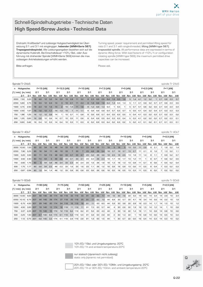
2:1 3:1 Nm kW Nm kW Nm kW Nm kW Nm kW Nm kW Nm kW Nm kW Nm kW Nm kW Nm kW Nm kW Nm kW Nm kW
[1/min] (m/min) 2:1 3:1 2:1 3:1 2:1 3:1 2:1 3:1 2:1 3:1 2:1 3:1 2:1 3:1
n Hubgeschw. F=15 [kN] F=12,5 [kN] F=10 [kN] F=7,5 [kN] F=5 [kN] F=2,5 [kN] F=1 [kN]
3000 7,50 5,00 16 4,6 12 3,2 14 3,9 10 2,8 11 3,2 8 2,3 8,9 2,6 6,4 1,9 6,5 1,9 5 1,4 4,1 1,2 3,2 1 2,7 0,8 2,3 0,7
2250 5,60 3,75 16 3,5 12 2,4 14 3 10 2,1 11 2,4 8 1,8 8,9 1,9 6,4 1,4 6,5 1,4 5 1,1 4,1 0,9 3,2 0,7 2,7 0,6 2,3 0,5
1500 3,75 2,50 16 2,3 12 1,6 14 2 10 1,4 11 1,6 8 1,2 8,9 1,3 6,4 1 6,5 1 5 0,7 4,1 0,6 3,2 0,5 2,7 0,4 2,3 0,4
1000 2,50 1,67 16 1,6 12 1,1 14 1,3 10 1 11 1,1 8 0,8 8,9 0,9 6,4 0,7 6,5 0,7 5 0,5 4,1 0,4 3,2 0,4 2,7 0,3 2,3 0,3
750 1,88 1,25 16 1,2 12 0,8 14 1 10 0,7 11 0,8 8 0,6 8,9 0,7 6,4 0,5 6,5 0,5 5 0,4 4,1 0,3 3,2 0,3 2,7 0,2 2,3 0,2
500 1,25 0,83 16 0,8 12 0,6 14 0,7 10 0,5 11 0,6 8 0,4 8,9 0,5 6,4 0,3 6,5 0,4 5 0,3 4,1 0,2 3,2 0,2 2,7 0,2 2,3 0,1
250 0,63 0,42 16 0,4 12 0,3 14 0,4 10 0,3 11 0,3 8 0,2 8,9 0,3 6,4 0,2 6,5 0,2 5 0,2 4,1 0,1 3,2 0,1 2,7 0,1 2,3 0,1
Drehzahl, Kraftbedarf und zulässige Hubgeschwindigkeit bei Über-setzung 2:1 und 3:1 mit eingängiger, hebender (WMH-Serie 567) Trapezgewindespindel. Alle Leistungsangaben beziehen sich auf die dynamische Hubkraft. Bei Einschaltdauer <10%/Std., oder Aus-führung mit drehender Spindel (WMH-Serie 569) können die max. zulässigen Antriebsleistungen erhöht werden.
Bitte anfragen.
Turning speed, power requirement and permitted lifting speed for ratio 2:1 and 3:1 with single-threaded, lifting (WMH type 567) trapezoidal spindle. All performance data are expressed in terms of dynamic lifting force. With load factors of <10%/h or confi guration rotating spindle (WMH type 569), the maximum permitted drive capacities can be increased.
Please ask.
10% ED/1Std. und Umgebungstemp. 20°C10% ED/1h and ambient temperature 20°C
nur statisch (dynamisch nicht zulässig)static only (dynamic not permitted)
20% ED/1Std. oder 30% ED/10Min. und Umgebungstemp. 20°C20% ED/1h or 30% ED/10min. and ambient temperature 20°C
Spindel Tr 24x5 spindle Tr 24x5
2:1 3:1 Nm kW Nm kW Nm kW Nm kW Nm kW Nm kW Nm kW Nm kW Nm kW Nm kW Nm kW Nm kW Nm kW Nm kW
[1/min] (m/min) 2:1 3:1 2:1 3:1 2:1 3:1 2:1 3:1 2:1 3:1 2:1 3:1 2:1 3:1
n Hubgeschw. F=50 [kN] F=30 [kN] F=20 [kN] F=15 [kN] F=10 [kN] F=5 [kN] F=2,5 [kN]
3000 10,50 7,00 80 22 54 15 48 14 33 9,3 33 9,3 23 6,4 26 7,1 18 5 18 5 13 3,5 11 2,8 8 2,1 7 1,8 5,2 1,4
2250 7,90 5,25 80 16 54 11 48 10 33 7 33 7 23 4,8 26 5,4 18 3,7 18 3,7 13 2,7 11 2,1 8 1,6 7 1,3 5,2 1,1
1500 5,20 3,50 80 11 54 7,5 48 6,8 33 4,7 33 4,7 23 3,2 26 3,6 18 2,5 18 2,5 13 1,8 11 1,4 8 1,1 7 0,9 5,2 0,7
1000 3,50 2,30 80 7,5 54 5 48 4,6 33 3,1 33 3,1 23 2,2 26 2,4 18 1,7 18 1,7 13 1,2 11 1 8 0,7 7 0,6 5,2 0,5
750 2,60 1,75 80 5 54 3,8 48 3,4 33 2,3 33 2,4 23 1,6 26 1,8 18 1,3 18 1,3 13 0,9 11 0,7 8 0,6 7 0,5 5,2 0,4
500 1,75 1,17 80 3,8 54 2,5 48 2,3 33 1,6 33 1,6 23 1,1 26 1,2 18 0,9 18 0,9 13 0,6 11 0,5 8 0,4 7 0,3 5,2 0,3
250 0,87 0,58 80 1,9 54 1,4 48 1,2 33 0,8 33 0,8 23 0,6 26 0,6 18 0,5 18 0,5 13 0,3 11 0,3 8 0,2 7 0,2 5,2 0,2
Spindel Tr 40x7 spindle Tr 40x7
2:1 3:1 Nm kW Nm kW Nm kW Nm kW Nm kW Nm kW Nm kW Nm kW Nm kW Nm kW Nm kW Nm kW Nm kW Nm kW
[1/min] (m/min) 2:1 3:1 2:1 3:1 2:1 3:1 2:1 3:1 2:1 3:1 2:1 3:1 2:1 3:1
n Hubgeschw. F=90 [kN] F=75 [kN] F=50 [kN] F=25 [kN] F=10 [kN] F=5 [kN] F=2,5 [kN]
3000 13,50 9,00 207 58 140 39 174 49 118 33 119 33 81 22 63 17 44 12 30 7,6 22 5,5 19 4,5 14 3,4 14 2,9 10 2,4
2250 10,10 6,75 207 44 140 29 174 37 118 25 119 25 81 17 63 13 44 8,9 30 5,7 22 4,1 19 3,4 14 2,6 14 2,2 10 1,8
1500 6,75 4,50 207 29 140 20 174 24 118 16 119 16 81 11 63 8,5 44 5,9 30 3,8 22 2,8 19 2,3 14 1,7 14 1,5 10 1,2
1000 4,50 3,00 207 19 140 13 174 16 118 11 119 11 81 7,5 63 5,7 44 4 30 2,6 22 1,9 19 1,5 14 1,2 14 1 10 0,8
750 3,37 2,25 207 15 140 10 174 12 118 8,2 119 8,2 81 5,6 63 4,3 44 3 30 1,9 22 1,4 19 1,1 14 0,9 14 0,8 10 0,6
500 2,25 1,50 207 9,7 140 6,6 174 8,1 118 5,5 119 5,5 81 3,8 63 2,9 44 2 30 1,3 22 1 19 0,8 14 0,6 14 0,5 10 0,4
250 1,12 0,75 207 4,9 140 3,3 174 4,1 118 2,8 119 2,8 81 1,9 63 1,5 44 1 30 0,7 22 0,5 19 0,4 14 0,3 14 0,3 10 0,2
Spindel Tr 60x9 spindle Tr 60x9
Q 23
Schnell-Spindelhubgetriebe - Technische Daten
High Speed-Screw Jacks - Technical Data
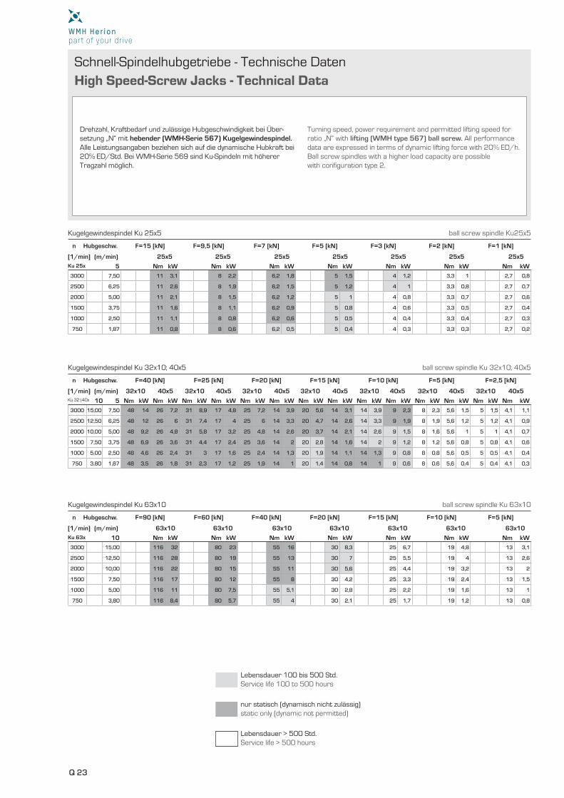
Ku 32|40x 10 5 Nm kW Nm kW Nm kW Nm kW Nm kW Nm kW Nm kW Nm kW Nm kW Nm kW Nm kW Nm kW Nm kW Nm kW
Ku 63x 10 Nm kW Nm kW Nm kW Nm kW Nm kW Nm kW Nm kW
[1/min] (m/min) 32x10 40x5 32x10 40x5 32x10 40x5 32x10 40x5 32x10 40x5 32x10 40x5 32x10 40x5
[1/min] (m/min) 63x10 63x10 63x10 63x10 63x10 63x10 63x10
n Hubgeschw. F=40 [kN] F=25 [kN] F=20 [kN] F=15 [kN] F=10 [kN] F=5 [kN] F=2,5 [kN]
n Hubgeschw. F=90 [kN] F=60 [kN] F=40 [kN] F=20 [kN] F=15 [kN] F=10 [kN] F=5 [kN]
3000 15,00 7,50 48 14 26 7,2 31 8,9 17 4,8 25 7,2 14 3,9 20 5,6 14 3,1 14 3,9 9 2,3 8 2,3 5,6 1,5 5 1,5 4,1 1,1
2500 12,50 6,25 48 12 26 6 31 7,4 17 4 25 6 14 3,3 20 4,7 14 2,6 14 3,3 9 1,9 8 1,9 5,6 1,2 5 1,2 4,1 0,9
2000 10,00 5,00 48 9,2 26 4,8 31 5,8 17 3,2 25 4,8 14 2,6 20 3,7 14 2,1 14 2,6 9 1,5 8 1,6 5,6 1 5 1 4,1 0,7
1500 7,50 3,75 48 6,9 26 3,6 31 4,4 17 2,4 25 3,6 14 2 20 2,8 14 1,6 14 2 9 1,2 8 1,2 5,6 0,8 5 0,8 4,1 0,6
1000 5,00 2,50 48 4,6 26 2,4 31 3 17 1,6 25 2,4 14 1,3 20 1,9 14 1,1 14 1,3 9 0,8 8 0,8 5,6 0,5 5 0,5 4,1 0,4
750 3,80 1,87 48 3,5 26 1,8 31 2,3 17 1,2 25 1,9 14 1 20 1,4 14 0,8 14 1 9 0,6 8 0,6 5,6 0,4 5 0,4 4,1 0,3
3000 15,00 116 32 80 23 55 16 30 8,3 25 6,7 19 4,8 13 3,1
2500 12,50 116 28 80 19 55 13 30 7 25 5,5 19 4 13 2,6
2000 10,00 116 22 80 15 55 11 30 5,6 25 4,4 19 3,2 13 2
1500 7,50 116 17 80 12 55 8 30 4,2 25 3,3 19 2,4 13 1,5
1000 5,00 116 11 80 7,5 55 5,1 30 2,8 25 2,2 19 1,6 13 1
750 3,80 116 8,4 80 5,7 55 4 30 2,1 25 1,7 19 1,2 13 0,8
Drehzahl, Kraftbedarf und zulässige Hubgeschwindigkeit bei Über-setzung „N“ mit hebender (WMH-Serie 567) Kugelgewindespindel. Alle Leistungsangaben beziehen sich auf die dynamische Hubkraft bei 20% ED/Std. Bei WMH-Serie 569 sind Ku-Spindeln mit höherer Tragzahl möglich.
Turning speed, power requirement and permitted lifting speed for ratio „N“ with lifting (WMH type 567) ball screw. All performance data are expressed in terms of dynamic lifting force with 20% ED/h. Ball screw spindles with a higher load capacity are possible with configuration type 2.
Ku 25x 5 Nm kW Nm kW Nm kW Nm kW Nm kW Nm kW Nm kW
[1/min] (m/min) 25x5 25x5 25x5 25x5 25x5 25x5 25x5
n Hubgeschw. F=15 [kN] F=9,5 [kN] F=7 [kN] F=5 [kN] F=3 [kN] F=2 [kN] F=1 [kN]
3000 7,50 11 3,1 8 2,2 6,2 1,8 5 1,5 4 1,2 3,3 1 2,7 0,8
2500 6,25 11 2,6 8 1,9 6,2 1,5 5 1,2 4 1 3,3 0,8 2,7 0,7
2000 5,00 11 2,1 8 1,5 6,2 1,2 5 1 4 0,8 3,3 0,7 2,7 0,6
1500 3,75 11 1,6 8 1,1 6,2 0,9 5 0,8 4 0,6 3,3 0,5 2,7 0,4
1000 2,50 11 1,1 8 0,8 6,2 0,6 5 0,5 4 0,4 3,3 0,4 2,7 0,3
750 1,87 11 0,8 8 0,6 6,2 0,5 5 0,4 4 0,3 3,3 0,3 2,7 0,2
Lebensdauer 100 bis 500 Std.Service life 100 to 500 hours
nur statisch (dynamisch nicht zulässig)static only (dynamic not permitted)
Lebensdauer > 500 Std.Service life > 500 hours
Kugelgewindespindel Ku 25x5 ball screw spindle Ku25x5
Kugelgewindespindel Ku 32x10; 40x5 ball screw spindle Ku 32x10; 40x5
Kugelgewindespindel Ku 63x10 ball screw spindle Ku 63x10
Q 24
Q
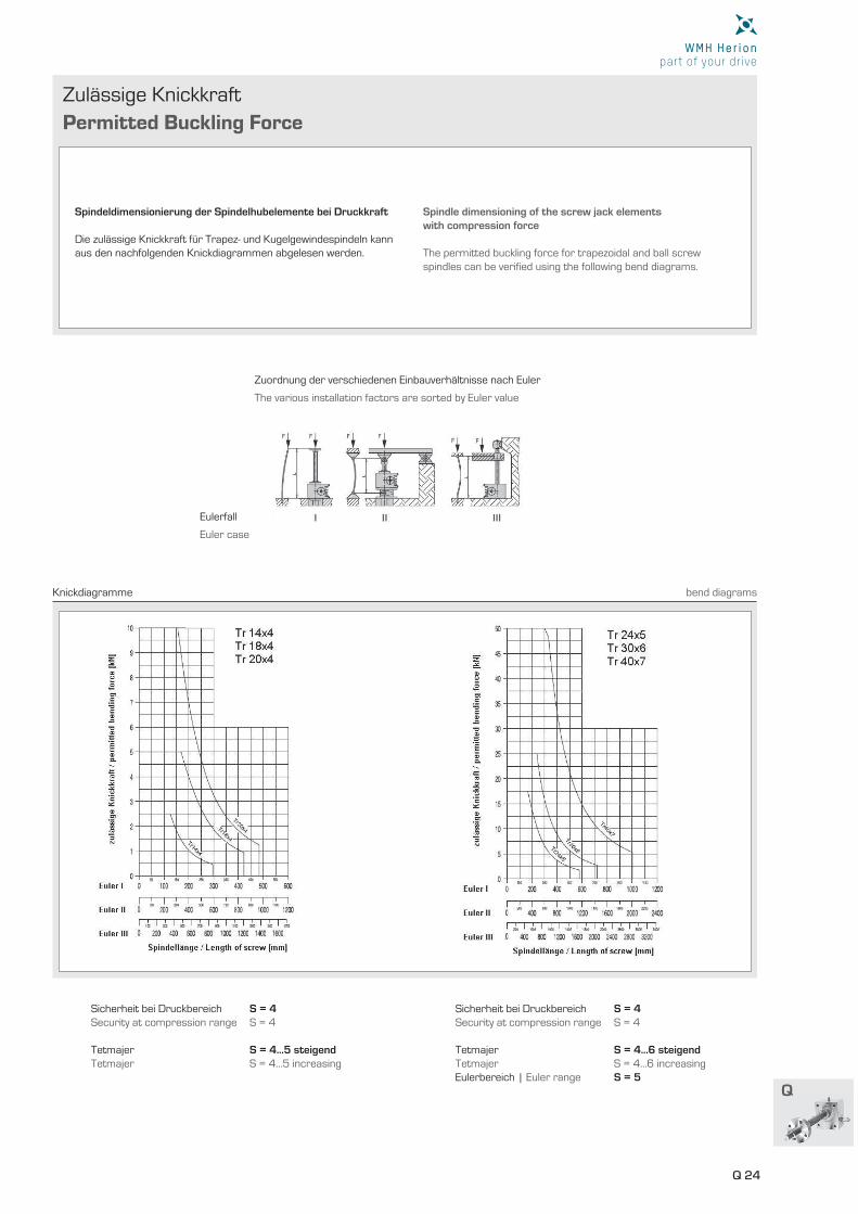
Zulässige Knickkraft
Permitted Buckling Force
Spindeldimensionierung der Spindelhubelemente bei Druckkraft Die zulässige Knickkraft für Trapez- und Kugelgewindespindeln kann aus den nachfolgenden Knickdiagrammen abgelesen werden.
Spindle dimensioning of the screw jack elements with compression force
The permitted buckling force for trapezoidal and ball screw spindles can be verifi ed using the following bend diagrams.
Sicherheit bei Druckbereich S = 4Security at compression range S = 4
Tetmajer S = 4…5 steigendTetmajer S = 4…5 increasing
Sicherheit bei Druckbereich S = 4Security at compression range S = 4
Tetmajer S = 4…6 steigendTetmajer S = 4…6 increasingEulerbereich | Euler range S = 5
Knickdiagramme bend diagrams
Zuordnung der verschiedenen Einbauverhältnisse nach Euler
Eulerfall
The various installation factors are sorted by Euler value
Euler case
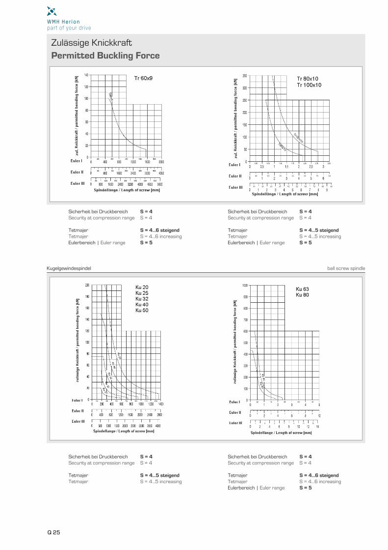
Q 25
Zulässige Knickkraft
Permitted Buckling Force
Sicherheit bei Druckbereich S = 4Security at compression range S = 4
Tetmajer S = 4…5 steigendTetmajer S = 4…5 increasing
Sicherheit bei Druckbereich S = 4Security at compression range S = 4
Tetmajer S = 4…6 steigendTetmajer S = 4…6 increasingEulerbereich | Euler range S = 5
Sicherheit bei Druckbereich S = 4Security at compression range S = 4
Tetmajer S = 4…6 steigendTetmajer S = 4…6 increasingEulerbereich | Euler range S = 5
Sicherheit bei Druckbereich S = 4Security at compression range S = 4
Tetmajer S = 4…5 steigendTetmajer S = 4…5 increasingEulerbereich | Euler range S = 5
Kugelgewindespindel ball screw spindle
Q 26
Q
Anfrageformular
Inquiry Form
Kunde / Firma | customer / company
Kundennummer | customer number
Straße | street
PLZ | postal code
Ort | city
Land | country
Ansprechpartner | contact person
Telefon | phone Fax | fax
E-Mail | e-mail
Datum | date
Pro Anlage | per unit dynamisch | dynamic kN statisch | static kN
Pro Spindel | per spindle dynamisch | dynamic kN statisch | static kN
Axiale Belastung der Spindeln | axial strain on the spindles
Für den Einsatz von WMH Spindelhubelementen | for the operation of WMH worm gear screw jacks 1kN = 1000N 10N~1kp
Anzahl der Anlagen | number of units
Anzahl der Hubelemente pro Anlage | number of lifting elements per unit
Die maximale Belastung ist in jedem Falle von der Hubhöhe, der zusätzlichen Führung und der geforderten Hubgeschwindigkeit abhän-gig. Um die bestgeeignete Hubanlage anbieten bzw. liefern zu können, bitten wir um folgende Angaben:
In welcher Anlage bzw. Maschine werden die
Hubelemente eingesetzt?
Wir empfehlen eine Zeichnung einzusenden, in der die Anordnung der Hubelemente, die Funktion, die Hauptmaße und - wenn vorhanden - die zusätzlichen Führungen angegeben sind.
Maximum load is in any case dependent on stroke-height, additional guiding devices and required lifting speed. In order to let us offer you the best-possible jacking system for your application, please provide us with the following details:
In what type of system or machine are the lifting
elements being used?
We recommend that you send us a diagram showing how the lifting elements are arranged, indicating their functions and main dimensi-ons, and – if fi tted – the position of any additional guide elements.
Belastungsart | type of load Zug | tension Druck | compression Zug und Druck | tension and compression
Vibration | vibration nein | no ja | yes
Stoß- oder Schlagkräfte | impact or collision damage nein | no ja | yes
Kundenorientierte Lösungen
AUF ANFRAGE
Q 27
Anfrageformular
Inquiry Form
Lastspiele pro Stunde | stress reversals per hour
Tage je Woche | days per week
Stunden pro Tag | hours per day
Zurückgelegter Weg je Lastspiel | distance covered by each stress reversal mm
kurze/lange Sicherheitsmutter | short/long safety nut(siehe Seiten | see pages Q 11 - Q 12)
EN 1570, EN 280, EN 1756, EN 1493
(ehem. | ex. VGB 14) und | and BGV C1 (ehem. | ex. VGB 70)
ja | yes nein | no
Wie oft ist die Anlage in Betrieb | how often is the unit used?
Wirken seitliche Kräfte | is lateral strain present?
Wenn ja, wie groß sind sie und wo greifen sie an? Bitte in Zeichnung eintragen.If yes, how much strain, and what points does it affect? Please include these details in a drawing.
ja | yes nein | no
Gewünschter Nutzhub | desired useful stroke distance mm
Sind seitliche Führungen vorgesehen | are lateral guides fitted? ja | yes nein | no
Gewünschte Hubgeschwindigkeit | desired lifting speed mm/min
Umgebungstemperatur | ambient temperature ° C
Soll die Anlage von Hand oder mit E-Motor angetrieben werden?Is the unit to be manually operated or actuated by electric motor?
Handantrieb Manual operation
Motorantrieb Motor drive
Wie werden die Spindeln eingebaut | how are the spindels installed? vertikal | vertically horizontal | horizontally
Seitliche Belastung der Spindeln | lateral strain on the spindles
Bitte notieren Sie hier alle anderen außergewöhnlichen Betriebsbedingungen - diese sind für die Funktion der Hubelemente von großer Wichtigkeit!
z.B. Holzstaub, Zementstaub, Luftfeuchtigkeit in %, Haltegenau-igkeit, keine/schlechte Nachschmiermöglichkeit usw.
Sind besondere Sicherheitsbestimmungen der Berufsge-nossenschaft (z.B. für Hebebühnen) oder des Technischen Überwachungsvereins zu beachten?
Wenn ja, welche?
Please note below all out-of-the ordinary operating conditions – they may prove to be of high importance for the functioning of lifting elements.
e. g. the presence of sawdust, cement dust, air humidity (in %), stopping accuracy, absence of or insufficient lubrication, etc.
Are any local-authority or professional-association rules to be observed with respect to accident prevention measures (e. g. for the operation of lifting platforms)?
If yes, which ones?
Kundenorientierte Lösungen
AUF ANFRAGE
Q 28
Q
Anfrageformular
Inquiry Form
Welche Teile sollen wir Ihnen zur Anlage anbieten | which parts would you like us to supply for the unit?
Die Richtigkeit der Angaben wird hiermit bestätigt | validity of data is hereby confi rmed:
Firmenstempel und Unterschrift | company stamp and signature
Name in Druckbuchstaben | name in print Ort | city Datum | date
Ausführung | design
Kopfausführung | head type Befestigungsplatte | top plate Gabelkopf | clevis
Gewinde | thread Stangenkopf | rod head
Ausführung | design
Kopfausführung | head type ja | yes nein | no
Ausführung | design
Übersetzung | ratio 1:1 2:1 3:1 4:1 5:1
Spannung | voltage [V]
Frequenz | frequency [Hz]
Schutzart | protection rating
(Abstandsmaße der Hubelemente oder Wellenlänge angeben)(indicate clearance distances jacking elements or shaft length)
Hubelemente mit axial beweglicher Spindel
Screw jacks with axially mobile spindle
562-…-… (Standard-Spindelhubgetriebe | standard screw jack)
567-…-… (Schnell-Spindelhubgetriebe | high-speed screw jack)
Hubelemente mit drehender Spindel und Laufmutter
Screw jacks with rotating spindle and travelling nut
563-…-… (Standard-Spindelhubgetriebe | standard screw jack)
569-…-… (Schnell-Spindelhubgetriebe | high-speed screw jack)
Kegelradgetriebe | bevel gear units ja | yes nein | no
Motor | motor ja | yes nein | no
Hochelastische Gelenkwellen | high fl exible shafts ja | yes nein | no
Kupplungen | couplings ja | yes nein | no
Stehlager | pedestal bearing ja | yes nein | no
Motorglocken | motor fl ange ja | yes nein | no
Zubehör | accessories ja | yes nein | no
Je 1 Faltenbalg | 1 bellow each screw jack ja | yes nein | no
Optionen | options
Je 2 Faltenbälge | 2 bellows each screw jack ja | yes nein | no
Optionen | options
Sollen Hubelemente mit Kugelgewindespindel, mehrgängigen Spindeln
oder Schnellhubgetriebe angeboten werden, bitten wir dies durch eine
Bemerkung zu ergänzen.
If lifting elements with ball screw spindles, multi-thread spindles or
high-speed screw jacks are to be supplied, please indicate accordingly.
Customized Solutionsavailable on
Request