Embed Size (px)
Citation preview
SPK-Werkzeuge für HartwerkstoffeSPK Tools for hard materials
Outils SPK pour l’usinage de matériaux durs
bei Gusseisen und gehärtetem Stahl
on cast iron and hardened steel
SPK Cutting Tool Division

3
bei Gusseisen und gehärtetem Stahl
on cast iron and hardened steel
Tel: +49 7163 166-239 Fax: +49 7163 166-388 E-Mail: [email protected] www.ceramtec.com
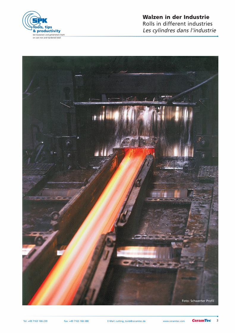
Walzen in der IndustrieRolls in different industriesLes cylindres dans l'industrie
Foto: Schwerter Profil
4
bei Gusseisen und gehärtetem Stahl
on cast iron and hardened steel
Tel: +49 7163 166-239 Fax: +49 7163 166-388 E-Mail: [email protected] www.ceramtec.com
Walzen in der IndustrieRolls in different industriesLes cylindres dans l'industrie
SphärogusswalzenSpheroidal cast iron rollCylindres en fonte nodulaire
Gusseiserne Walzen ohne Graphit in der ArbeitsschichtCast iron rolls without graphite in the working layerCylindres en fonte sans graphite dans la couche de travail
Gusseiserne Walzen mit Lamellengraphit in der ArbeitsschichtCast iron rolls with flake graphite in the working layerCylindres en fonte avec graphite à lamelles dans la couche de travail
HartgusswalzenChilled cast iron rollsCylindres en fonte trempée
Werkstoffe Materials Matériaux
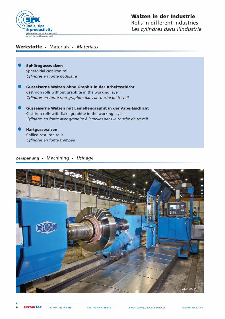
Zerspanung Machining Usinage
Foto: WZM
5
bei Gusseisen und gehärtetem Stahl
on cast iron and hardened steel
Tel: +49 7163 166-239 Fax: +49 7163 166-388 E-Mail: [email protected] www.ceramtec.com
Walzen in der IndustrieRolls in different industriesLes cylindres dans l'industrie
Schneidstoffe Cutting materials Nuances de coupe
Mischkeramiken ssind VVerbundwerkstoffe
aus AAluminiumoxid uund eeinem
Titanhartstoff mmit aausgezeichneter
Verschleißfestigkeit uund KKantenstabilität
auch bbei hhohen TTemperaturen. DDie
Einsatzgebiete vvon MMischkeramiken lliegen
im HHart-FFeindrehen vvon ggehärteten
Stählen, iim HHartdrehen vvon WWalzen, ssowie
in dder FFeinbearbeitung vvon WWerkstücken
aus GGrauguss.
SH 2 besitzt eein eextrem hhomogenes
Submirkongefüge. DDieses bbewirkt eeine
erhöhte mmechanische uund tthermische
Belastbarkeit uund eermöglicht eeine hhochge-
naue AAusführung dder SSchneidkanten. DDie
Mischkeramiksorte ffür ddie HHart-
Feinbearbeitung iim gglatten SSchnitt.
SH 3 Die MMischkeramiksorte vverfügt üüber
eine ggesteigerte VVerschleißfestigkeit bbei
gleichzeitig ssehr gguter ZZähigkeit uund hhoher
Kantenstabilität. DDer IIdeale SSchneidstoff ffür
die WWalzenbearbeitung, aaber aauch ffür ddas
Schlichten vvon GGG uund GGGG iim gglatten
oder uunterbrochenen SSchnitt.
SPK-Mischkeramik
Mixed ceramics constitute composite mate-
rials consisting of aluminum oxide and a
titanium material, and offer excellent wear
resistance and edge stability even at high
temperatures. Mixed ceramics are particu-
larly used for finish turning of hardened
steels, for hard turning of rolls and for fine
machining of grey cast iron parts.
SH 2 Grade offering an extremely homo-
genous submicron structure which enables
high mechanical and thermal resistance and
highly precise cutting edges. Mixed ceramic
grade for hard fine machining in continu-
ous cutting.
SH 3 Mixed ceramic grade offering high
wear resistance, very good tenacity and
high edge stability. This cutting material is
perfectly suited for machining of rolls.
Additionally it is providing convincing
results in finishing grey cast iron and nodu-
lar cast iron in continuous or intermittent
cutting.
SPK mixed ceramics
Les céramiques mixtes sont des matériaux
composites faits d’oxyde d’aluminium et
d’un titane dur dotés d’une remarquable
résistance à l’usure ainsi que d’une excel-
lente stabilité d’arêtes, même à hautes tem-
pératures. Les domaines d’utilisation des
céramiques mixtes se trouvent dans le tour-
nage dur et fin d’aciers trempés, dans le
tournage dur de galets et de cylindres ainsi
que dans l’usinage fin de pièces en fonte
grise.
La SH 2 possède une structure micromo-
léculaire extrêmement homogène. Elle a
pour effet une stabilité mécanique et ther-
mique élevée et autorise une réalisation très
précise des arêtes de coupe. Il s’agit de la
céramique mixte pour l’usinage dur et fin
en coupe continue.
SH 3 Cette céramique mixte est dotée
d’une résistance à l’usure augmentée tout
en conservant une très bonne ténacité et
une haute stabilité d’arêtes. Le matériau de
coupe idéal pour l’usinage de cylindres et
pour la finition des fontes et des fontes
ductiles en coupe continue et interromque.
Céramiques mixtes SPK
WBN 1100 ist ddie mmassive PPCBN-SSorte ffürdas SSchruppen uund SSchlichten vvonGraugusswerkstoffen ssowie ddie ZZer-spanung vvon HHartguss.
WBN 1101 ist mmit iihrer ooptimiertenZähigkeit uund VVerschleißfestigkeit aals mmassi-ve PPCBN-SSorte sspezialisiert aauf ddie BBear-beitung vvon HHartgusswalzen.
WBN 7750 ist ddie TTopsorte ffür aan-spruchsvolle SSchrupp- uund SSchlichtbe-arbeitungen sspeziell vvon HHartmetallwalzen.Für SStechbearbeitungen uund ddas WWal-zendrehen eempfiehlt ssich ddie WWBN 7750 aalsflächig bbelegte SSchneidplatte.
WBN 1100 is a solid PCBN grade forrough machining and finishing of grey castiron0 and for machining chilled cast iron.
WBN 1101 is a solid PCBN grade, andowing to its optimized toughness and wearresistance is particularly suited for machi-ning rolls made of chilled cast iron.
WBN 7750 is a top grade for rough andfinish machining of rolls. For roll turningand for grooving, we recommend gradeWBN 750 as full face laminated insert.
WBN 1100 est la nuance PCBN massivedestinées à la finition et à l’ébauche defonte grise ainsi qu'à l'usinage de la fontetrempée.
WBN 1101 est une nuance PCBN massivequi grâce à sa ténacité et sa résistance àl'usure optimisées, qui est réputée dansl'usinage des cylindres en fonte trempée.
WBN 7750 est la nuance idéale pour l' ébauche et la finition des cylindres carbu-res applications et les applications de plon-gées de gorge, nous recommandons cettenuance en plaquette fullface.
SPK-PCBN-Sorten SPK PCBN grades Nuances de PCBN SPK
6
bei Gusseisen und gehärtetem Stahl
on cast iron and hardened steel
Tel: +49 7163 166-239 Fax: +49 7163 166-388 E-Mail: [email protected] www.ceramtec.com
Walzen in der IndustrieRolls in different industriesLes cylindres dans l'industrie
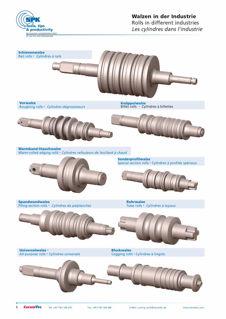
Universalwalze All-purpose rolls Cylindres universels
VorwalzeRoughing rolls Cylindres dégrossisseurs
KnüppelwalzeBillet rolls Cylindres à billettes
Warmband-StauchwalzeWarm-rolled edging rolls Cylindres refouleurs de feuillard à chaud
RohrwalzeTube rolls Cylindres à tuyaux
SpundwandwalzePiling section rolls Cylindres de palplanches
SchienenwalzeRail rolls Cylindres à rails
SonderprofilwalzeSpecial section rolls Cylindres à profilés spéciaux
BlockwalzeCogging rolls Cylindres à lingots
7
bei Gusseisen und gehärtetem Stahl
on cast iron and hardened steel
Tel: +49 7163 166-239 Fax: +49 7163 166-388 E-Mail: [email protected] www.ceramtec.com
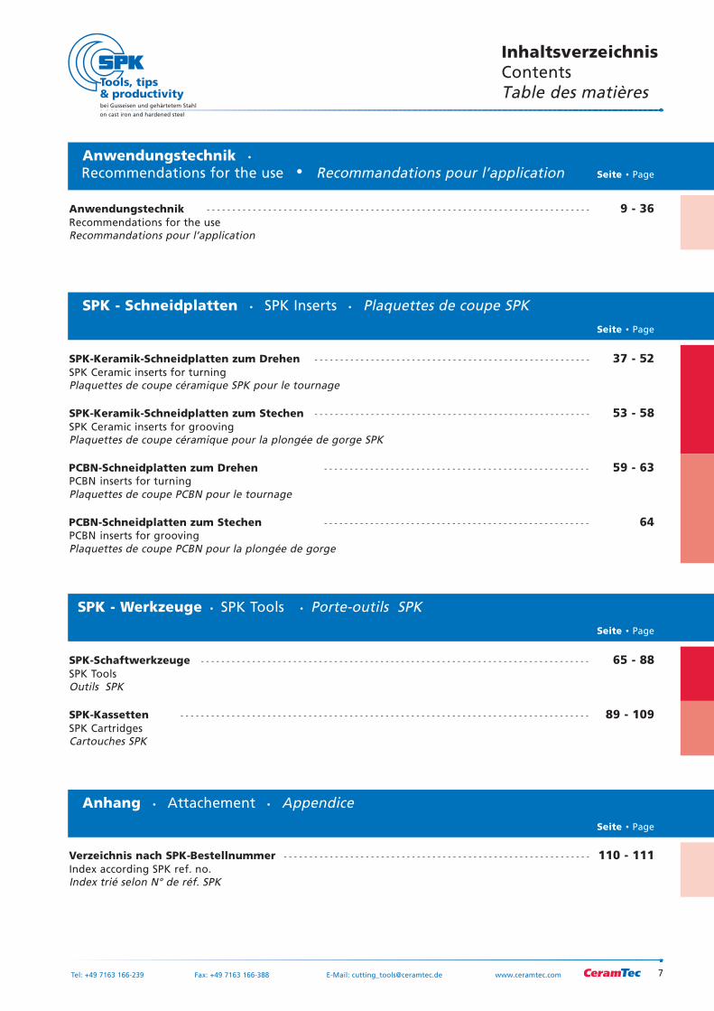
Inhaltsverzeichnis ContentsTable des matières
SPK - Schneidplatten SPK Inserts Plaquettes de coupe SPK
Seite Page
SPK-Keramik-Schneidplatten zum Drehen - - - - - - - - - - - - - - - - - - - - - - - - - - - - - - - - - - - - - - - - - - - - - - - - - - - - - - 37 - 52SPK Ceramic inserts for turningPlaquettes de coupe céramique SPK pour le tournage
SPK-Schaftwerkzeuge - - - - - - - - - - - - - - - - - - - - - - - - - - - - - - - - - - - - - - - - - - - - - - - - - - - - - - - - - - - - - - - - - - - - - - - - - - - - 65 - 88SPK Tools Outils SPK
SPK-Kassetten - - - - - - - - - - - - - - - - - - - - - - - - - - - - - - - - - - - - - - - - - - - - - - - - - - - - - - - - - - - - - - - - - - - - - - - - - - - - - - - - 89 - 109SPK Cartridges Cartouches SPK
SPK-Keramik-Schneidplatten zum Stechen - - - - - - - - - - - - - - - - - - - - - - - - - - - - - - - - - - - - - - - - - - - - - - - - - - - - - - 53 - 58SPK Ceramic inserts for groovingPlaquettes de coupe céramique pour la plongée de gorge SPK
PCBN-Schneidplatten zum Drehen - - - - - - - - - - - - - - - - - - - - - - - - - - - - - - - - - - - - - - - - - - - - - - - - - - - - 59 - 63PCBN inserts for turningPlaquettes de coupe PCBN pour le tournage
PCBN-Schneidplatten zum Stechen - - - - - - - - - - - - - - - - - - - - - - - - - - - - - - - - - - - - - - - - - - - - - - - - - - - - 64PCBN inserts for groovingPlaquettes de coupe PCBN pour la plongée de gorge
SPK - Werkzeuge SPK Tools Porte-outils SPK
Seite Page
Anhang Attachement Appendice
Seite Page
Anwendungstechnik - - - - - - - - - - - - - - - - - - - - - - - - - - - - - - - - - - - - - - - - - - - - - - - - - - - - - - - - - - - - - - - - - - - - - - - - - - - 9 - 36Recommendations for the useRecommandations pour l’application
AnwendungstechnikRecommendations for the use Recommandations pour l’application Seite Page
Verzeichnis nach SPK-Bestellnummer - - - - - - - - - - - - - - - - - - - - - - - - - - - - - - - - - - - - - - - - - - - - - - - - - - - - - - - - - - - - 110 - 111Index according SPK ref. no.Index trié selon N° de réf. SPK

8
bei Gusseisen und gehärtetem Stahl
on cast iron and hardened steel
Tel: +49 7163 166-239 Fax: +49 7163 166-388 E-Mail: [email protected] www.ceramtec.com
9
bei Gusseisen und gehärtetem Stahl
on cast iron and hardened steel
Tel: +49 7163 166-239 Fax: +49 7163 166-388 E-Mail: [email protected] www.ceramtec.com
AnwendungstechnikRecommendations for the use
Recommandations pour l’application
10
bei Gusseisen und gehärtetem Stahl
on cast iron and hardened steel
Tel: +49 7163 166-239 Fax: +49 7163 166-388 E-Mail: [email protected] www.ceramtec.com
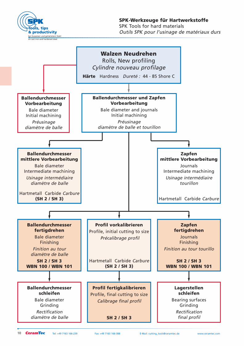
SPK-Werkzeuge für HartwerkstoffeSPK Tools for hard materialsOutils SPK pour l’usinage de matériaux durs
Walzen NeudrehenRolls, New profiling
Cylindre nouveau profilageHärte Hardness Dureté : 44 - 85 Shore C
BallendurchmesserVorbearbeitung
Bale diameterInitial machining
Préusinage diamètre de balle
Ballendurchmesser und ZapfenVorbearbeitung
Bale diameter and journalsInitial machining
Préusinage diamètre de balle et tourillon
Ballendurchmessermittlere Vorbearbeitung
Bale diameterIntermediate machiningUsinage intermédiaire
diamètre de balle
Hartmetall Carbide Carbure(SH 2 / SH 3)
Ballendurchmesserfertigdrehen Bale diameter
FinishingFinition au tour
diamètre de balleSH 2 / SH 3
WBN 100 / WBN 101
Profil vorkalibrierenProfile, initial cutting to size
Précalibrage profil
Hartmetall Carbide Carbure(SH 2 / SH 3)
Zapfenmittlere Vorbearbeitung
JournalsIntermediate machiningUsinage intermédiaire
tourillon
Hartmetall Carbide Carbure
Zapfenfertigdrehen
JournalsFinishing
Finition au tour tourillo
SH 2 / SH 3WBN 100 / WBN 101
Ballendurchmesserschleifen
Bale diameterGrinding
Rectification diamètre de balle
Profil fertigkalibrierenProfile, final cutting to size
Calibrage final profil
SH 2 / SH 3
Lagerstellenschleifen
Bearing surfacesGrinding
Rectification final profil
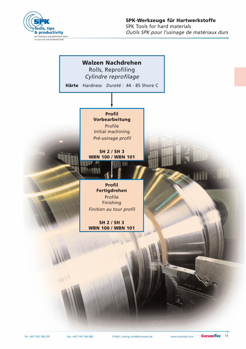
SPK-Werkzeuge für HartwerkstoffeSPK Tools for hard materialsOutils SPK pour l’usinage de matériaux durs
11
bei Gusseisen und gehärtetem Stahl
on cast iron and hardened steel
Tel: +49 7163 166-239 Fax: +49 7163 166-388 E-Mail: [email protected] www.ceramtec.com
Walzen NachdrehenRolls, Reprofiling
Cylindre reprofilageHärte Hardness Dureté : 44 - 85 Shore C
ProfilVorbearbeitung
ProfileInitial machiningPré-usinage profil
SH 2 / SH 3WBN 100 / WBN 101
ProfilFertigdrehen
ProfileFinishing
Finition au tour profil
SH 2 / SH 3WBN 100 / WBN 101
12
bei Gusseisen und gehärtetem Stahl
on cast iron and hardened steel
Tel: +49 7163 166-239 Fax: +49 7163 166-388 E-Mail: [email protected] www.ceramtec.com
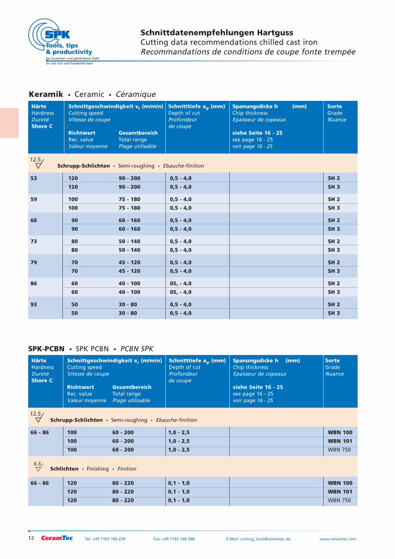
Schnittdatenempfehlungen HartgussCutting data recommendations chilled cast ironRecommandations de conditions de coupe fonte trempée
12.5
Keramik Ceramic CéramiqueHärte Schnittgeschwindigkeit vc (m/min) Schnitttiefe ap (mm) Spanungsdicke h (mm) SorteHardness Cutting speed Depth of cut Chip thickness GradeDureté Vitesse de coupe Profondeur Epaisseur de copeaux NuanceShore C de coupe
Richtwert Gesamtbereich siehe Seite 16 - 25Rec. value Total range see page 16 - 25Valeur moyenne Plage utilisable voir page 16 - 25
Schrupp-Schlichten Semi-roughing Ebauche-finition
53 120 90 - 200 0,5 - 4,0 SH 2
120 90 - 200 0,5 - 4,0 SH 3
59 100 75 - 180 0,5 - 4,0 SH 2
100 75 - 180 0,5 - 4,0 SH 3
66 90 60 - 160 0,5 - 4,0 SH 2
90 60 - 160 0,5 - 4,0 SH 3
73 80 50 - 140 0,5 - 4,0 SH 2
80 50 - 140 0,5 - 4,0 SH 3
79 70 45 - 120 0,5 - 4,0 SH 2
70 45 - 120 0,5 - 4,0 SH 3
86 60 40 - 100 05, - 4,0 SH 2
60 40 - 100 05, - 4,0 SH 3
93 50 30 - 80 0,5 - 4,0 SH 2
50 30 - 80 0,5 - 4,0 SH 3
Härte Schnittgeschwindigkeit vc (m/min) Schnitttiefe ap (mm) Spanungsdicke h (mm) SorteHardness Cutting speed Depth of cut Chip thickness GradeDureté Vitesse de coupe Profondeur Epaisseur de copeaux NuanceShore C de coupe
Richtwert Gesamtbereich siehe Seite 16 - 25Rec. value Total range see page 16 - 25Valeur moyenne Plage utilisable voir page 16 - 25
6.3
Schrupp-Schlichten Semi-roughing Ebauche-finition
66 - 86 100 60 - 200 1,0 - 2,5 WBN 100
100 60 - 200 1,0 - 2,5 WBN 101
100 60 - 200 1,0 - 2,5 WBN 750
Schlichten Finishing Finition
66 - 86 120 80 - 220 0,1 - 1,0 WBN 100
120 80 - 220 0,1 - 1,0 WBN 101
120 80 - 220 0,1 - 1,0 WBN 750
12.5
SPK-PCBN SPK PCBN PCBN SPK
13
bei Gusseisen und gehärtetem Stahl
on cast iron and hardened steel
Tel: +49 7163 166-239 Fax: +49 7163 166-388 E-Mail: [email protected] www.ceramtec.com
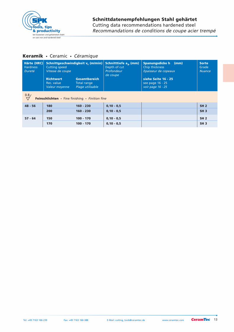
Schnittdatenempfehlungen Stahl gehärtetCutting data recommendations hardened steelRecommandations de conditions de coupe acier trempé
0.8Feinschlichten Fine finishing Finition fine
48 - 56 180 160 - 230 0,10 - 0,5 SH 2
200 160 - 230 0,10 - 0,5 SH 3
57 - 64 150 100 - 170 0,10 - 0,5 SH 2
170 100 - 170 0,10 - 0,5 SH 3
Keramik Ceramic CéramiqueHärte (HRC) Schnittgeschwindigkeit vc (m/min) Schnitttiefe ap (mm) Spanungsdicke h (mm) SorteHardness Cutting speed Depth of cut Chip thickness GradeDureté Vitesse de coupe Profondeur Epaisseur de copeaux Nuance
de coupeRichtwert Gesamtbereich siehe Seite 16 - 25Rec. value Total range see page 16 - 25Valeur moyenne Plage utilisable voir page 16 - 25
14
bei Gusseisen und gehärtetem Stahl
on cast iron and hardened steel
Tel: +49 7163 166-239 Fax: +49 7163 166-388 E-Mail: [email protected] www.ceramtec.com
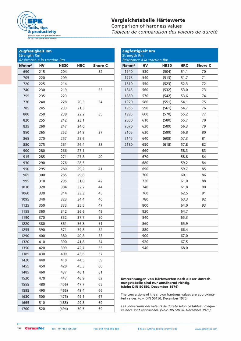
Zugfestigkeit RmStrength RmRésistance à la traction Rm
N/mm2 HV HB30 HRC Shore C
690 215 204 32
705 220 209
720 225 214
740 230 219 33
755 235 223
770 240 228 20,3 34
785 245 233 21,3
800 250 238 22,2 35
820 255 242 23,1
835 260 247 24,0
850 265 252 24,8 37
865 270 257 25,6
880 275 261 26,4 38
900 280 266 27,1
915 285 271 27,8 40
930 290 276 28,5
950 295 280 29,2 41
965 300 285 29,8
995 310 295 31,0 42
1030 320 304 32,2 44
1060 330 314 33,3 45
1095 340 323 34,4 46
1125 350 333 35,5 47
1155 360 342 36,6 49
1190 370 352 37,7 50
1220 380 361 36,8 51
1255 390 371 39,8 52
1290 400 380 40,8 53
1320 410 390 41,8 54
1350 420 399 42,7 55
1385 430 409 43,6 57
1420 440 418 44,5 59
1455 450 428 45,3 60
1485 460 437 46,1 61
1520 470 447 46,9 62
1555 480 (456) 47,7 65
1595 490 (466) 48,4 66
1630 500 (475) 49,1 67
1665 510 (485) 49,8 69
1700 520 (494) 50,5 69
Zugfestigkeit RmStrength RmRésistance à la traction Rm
N/mm2 HV HB30 HRC Shore C
1740 530 (504) 51,1 70
1775 540 (513) 51,7 71
1810 550 (523) 52,3 72
1845 560 (532) 53,0 73
1880 570 (542) 53,6 74
1920 580 (551) 54,1 75
1955 590 (561) 54,7 76
1995 600 (570) 55,2 77
2030 610 (580) 55,7 78
2070 620 (589) 56,3 79
2105 630 (599) 56,8 80
2145 640 (608) 57,3 81
2180 650 (618) 57,8 82
660 58,3 83
670 58,8 84
680 59,2 84
690 59,7 85
700 60,1 86
720 61,0 88
740 61,8 90
760 62,5 91
780 63,3 92
800 64,0 93
820 64,7
840 65,3
860 65,9
880 66,4
900 67,0
920 67,5
940 68,0
Vergleichstabelle HärtewerteComparison of hardness valuesTableau de comparaison des valeurs de dureté
Umrechnungen von Härtewerten nach dieser Umrech-nungstabelle sind nur annähernd richtig. (siehe DIN 50150, Dezember 1976)
The conversions of the shown hardness values are approxima-ted values. (q.v. DIN 50150, December 1976)
Les conversions des valeurs de dureté selon ce tableau d'équi-valence sont approchées. (Voir DIN 50150, Décembre 1976)
15
bei Gusseisen und gehärtetem Stahl
on cast iron and hardened steel
Tel: +49 7163 166-239 Fax: +49 7163 166-388 E-Mail: [email protected] www.ceramtec.com
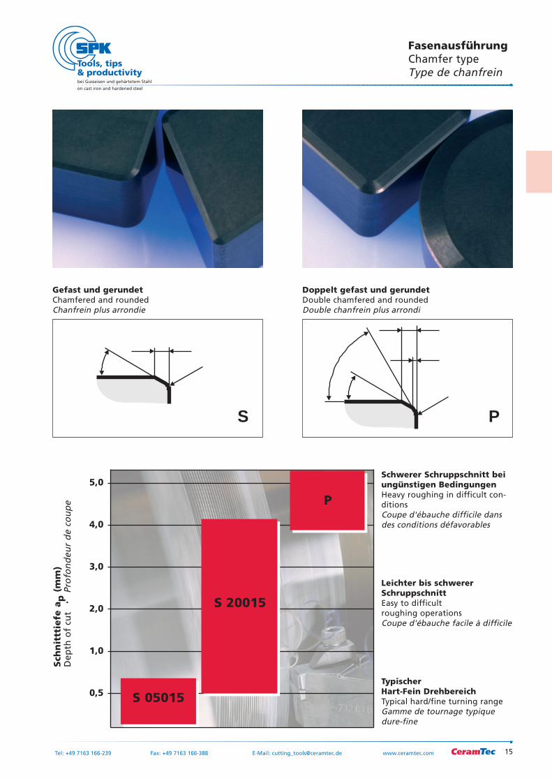
FasenausführungChamfer typeType de chanfrein
0,5
1,0
2,0
3,0
4,0
5,0
Sch
nit
ttie
fe a
p(m
m)
Dep
th o
f cu
t
Pro
fon
deu
r d
e co
up
e
Doppelt gefast und gerundetDouble chamfered and roundedDouble chanfrein plus arrondi
Gefast und gerundetChamfered and roundedChanfrein plus arrondie
S P
P
S 20015
S 05015
Schwerer Schruppschnitt beiungünstigen BedingungenHeavy roughing in difficult con-ditionsCoupe d'ébauche difficile dansdes conditions défavorables
Leichter bis schwererSchruppschnittEasy to difficult roughing operationsCoupe d'ébauche facile à difficile
Typischer Hart-Fein DrehbereichTypical hard/fine turning rangeGamme de tournage typiquedure-fine
16
bei Gusseisen und gehärtetem Stahl
on cast iron and hardened steel
Tel: +49 7163 166-239 Fax: +49 7163 166-388 E-Mail: [email protected] www.ceramtec.com
Typische Eingriffsverhältnisse beim Längsdrehen von harten WalzenTypical features when longitudinal turning of hard rollsConditions caractéristiques pour le tournage longitudinal des cylindres durs
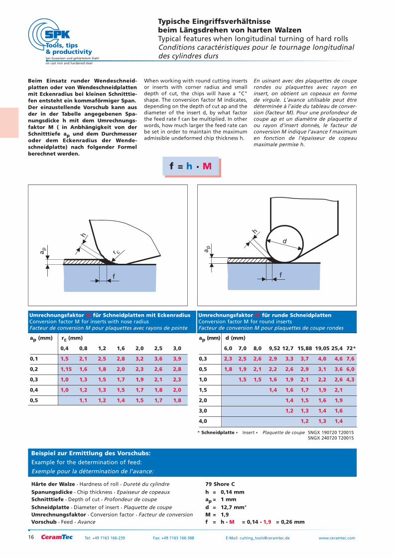
Beim Einsatz runder Wendeschneid-platten oder von Wendeschneidplattenmit Eckenradius bei kleinen Schnitttie-fen entsteht ein kommaförmiger Span.Der einzustellende Vorschub kann ausder in der Tabelle angegebenen Spa-nungsdicke h mit dem Umrechnungs-faktor M ( in Anbhängigkeit von derSchnitttiefe ap und dem Durchmesseroder dem Eckenradius der Wende-schneidplatte) nach folgender Formelberechnet werden.
When working with round cutting insertsor inserts with corner radius and smalldepth of cut, the chips will have a "C"shape. The conversion factor M indicates,depending on the depth of cut ap and thediameter of the insert d, by what factorthe feed rate f can be multiplied. In otherwords, how much larger the feed rate canbe set in order to maintain the maximumadmissible undeformed chip thickness h.
En usinant avec des plaquettes de couperondes ou plaquettes avec rayon eninsert, on obtient un copeaux en formede virgule. L’avance utilisable peut êtredéterminée à l’aide du tableau de conver-sion (facteur M). Pour une profondeur decoupe ap et un diamètre de plaquette dou rayon d’insert donnés, le facteur deconversion M indique l’avance f maximumen fonction de l’épaisseur de copeaumaximale permise h.
Umrechnungsfaktor M für Schneidplatten mit EckenradiusConversion factor M for inserts with nose radiusFacteur de conversion M pour plaquettes avec rayons de pointe
ap (mm) rεε (mm)
0,4 0,8 1,2 1,6 2,0 2,5 3,0
0,1 1,5 2,1 2,5 2,8 3,2 3,6 3,9
0,2 1,15 1,6 1,8 2,0 2,3 2,6 2,8
0,3 1,0 1,3 1,5 1,7 1,9 2,1 2,3
0,4 1,0 1,2 1,3 1,5 1,7 1,8 2,0
0,5 1,1 1,2 1,4 1,5 1,7 1,8
Umrechnungsfaktor M für runde SchneidplattenConversion factor M for round inserts Facteur de conversion M pour plaquettes de coupe rondes
ap (mm) d (mm)
6,0 7,0 8,0 9,52 12,7 15,88 19,05 25,4 72*
0,3 2,3 2,5 2,6 2,9 3,3 3,7 4,0 4,6 7,6
0,5 1,8 1,9 2,1 2,2 2,6 2,9 3,1 3,6 6,0
1,0 1,5 1,5 1,6 1,9 2,1 2,2 2,6 4,3
1,5 1,4 1,6 1,7 1,9 2,1
2,0 1,4 1,5 1,6 1,9
3,0 1,2 1,3 1,4 1,6
4,0 1,2 1,3 1,4
f
r �ap
h
ap
f
d
h
* Schneidplatte Insert Plaquette de coupe SNGX 190720 T20015SNGX 240720 T20015
f = h M
Beispiel zur Ermittlung des Vorschubs:
Example for the determination of feed:
Exemple pour la détermination de l’avance:
Härte der Walze Hardness of roll Dureté du cylindre 79 Shore C Spanungsdicke Chip thickness Epaisseur de copeaux h = 0,14 mmSchnitttiefe Depth of cut Profondeur de coupe ap = 1 mmSchneidplatte Diameter of insert Plaquette de coupe d = 12,7 mm°Umrechnungsfaktor Conversion factor Facteur de conversion M = 1,9Vorschub Feed Avance f = h M = 0,14 1,9 = 0,26 mm
17
bei Gusseisen und gehärtetem Stahl
on cast iron and hardened steel
Tel: +49 7163 166-239 Fax: +49 7163 166-388 E-Mail: [email protected] www.ceramtec.com
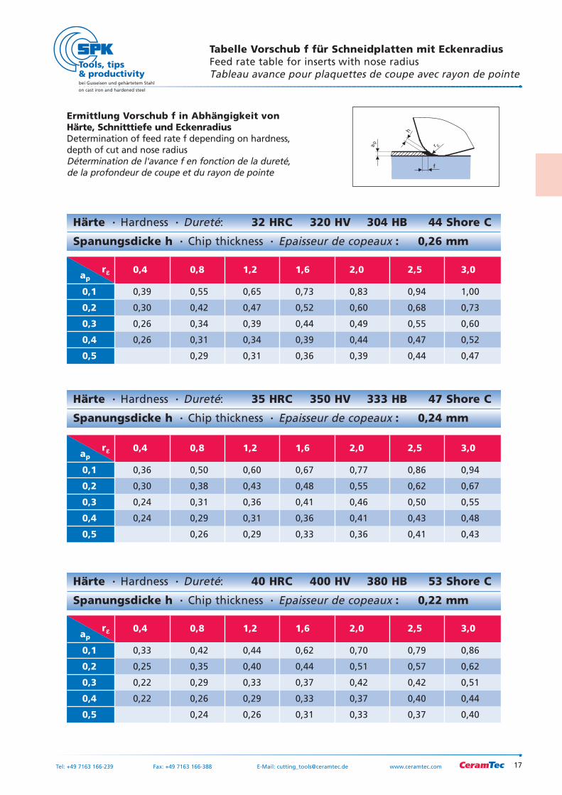
Ermittlung Vorschub f in Abhängigkeit von Härte, Schnitttiefe und EckenradiusDetermination of feed rate f depending on hardness,depth of cut and nose radiusDétermination de l'avance f en fonction de la dureté,de la profondeur de coupe et du rayon de pointe
Härte Hardness Dureté: 40 HRC 400 HV 380 HB 53 Shore C
Spanungsdicke h Chip thickness Epaisseur de copeaux : 0,22 mm
Härte Hardness Dureté: 32 HRC 320 HV 304 HB 44 Shore C
Spanungsdicke h Chip thickness Epaisseur de copeaux : 0,26 mm
rεεap0,4 0,8 1,2 1,6 2,0 2,5 3,0
0,1 0,39 0,55 0,65 0,73 0,83 0,94 1,00
0,2 0,30 0,42 0,47 0,52 0,60 0,68 0,73
0,3 0,26 0,34 0,39 0,44 0,49 0,55 0,60
0,4 0,26 0,31 0,34 0,39 0,44 0,47 0,52
0,5 0,29 0,31 0,36 0,39 0,44 0,47
rεεap0,4 0,8 1,2 1,6 2,0 2,5 3,0
0,1 0,36 0,50 0,60 0,67 0,77 0,86 0,94
0,2 0,30 0,38 0,43 0,48 0,55 0,62 0,67
0,3 0,24 0,31 0,36 0,41 0,46 0,50 0,55
0,4 0,24 0,29 0,31 0,36 0,41 0,43 0,48
0,5 0,26 0,29 0,33 0,36 0,41 0,43
rεεap0,4 0,8 1,2 1,6 2,0 2,5 3,0
0,1 0,33 0,42 0,44 0,62 0,70 0,79 0,86
0,2 0,25 0,35 0,40 0,44 0,51 0,57 0,62
0,3 0,22 0,29 0,33 0,37 0,42 0,42 0,51
0,4 0,22 0,26 0,29 0,33 0,37 0,40 0,44
0,5 0,24 0,26 0,31 0,33 0,37 0,40
Härte Hardness Dureté: 35 HRC 350 HV 333 HB 47 Shore C
Spanungsdicke h Chip thickness Epaisseur de copeaux : 0,24 mm
f
r �ap
h
Tabelle Vorschub f für Schneidplatten mit EckenradiusFeed rate table for inserts with nose radiusTableau avance pour plaquettes de coupe avec rayon de pointe
18
bei Gusseisen und gehärtetem Stahl
on cast iron and hardened steel
Tel: +49 7163 166-239 Fax: +49 7163 166-388 E-Mail: [email protected] www.ceramtec.com
f
r �ap
h
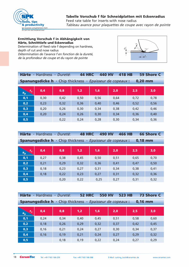
Härte Hardness Dureté: 52 HRC 550 HV 523 HB 73 Shore C
Spanungsdicke h Chip thickness Epaisseur de copeaux : 0,16 mm
Härte Hardness Dureté: 44 HRC 440 HV 418 HB 59 Shore C
Spanungsdicke h Chip thickness Epaisseur de copeaux : 0,20 mm
Härte Hardness Dureté: 48 HRC 490 HV 466 HB 66 Shore C
Spanungsdicke h Chip thickness Epaisseur de copeaux : 0,18 mm
rεεap0,4 0,8 1,2 1,6 2,0 2,5 3,0
0,1 0,24 0,34 0,40 0,45 0,51 0,58 0,60
0,2 0,18 0,26 0,29 0,32 0,37 0,42 0,45
0,3 0,16 0,21 0,24 0,27 0,30 0,34 0,37
0,4 0,16 0,19 0,21 0,24 0,27 0,29 0,32
0,5 0,18 0,19 0,22 0,24 0,27 0,29
rεεap0,4 0,8 1,2 1,6 2,0 2,5 3,0
0,1 0,27 0,38 0,45 0,50 0,51 0,65 0,70
0,2 0,21 0,29 0,32 0,36 0,41 0,47 0,50
0,3 0,18 0,23 0,27 0,31 0,34 0,38 0,41
0,4 0,18 0,22 0,23 0,27 0,31 0,32 0,36
0,5 0,20 0,22 0,25 0,27 0,31 0,32
rεεap0,4 0,8 1,2 1,6 2,0 2,5 3,0
0,1 0,30 0,42 0,50 0,56 0,64 0,72 0,78
0,2 0,23 0,32 0,36 0,40 0,46 0,52 0,56
0,3 0,20 0,26 0,30 0,34 0,38 0,42 0,46
0,4 0,20 0,24 0,26 0,30 0,34 0,36 0,40
0,5 0,22 0,24 0,28 0,30 0,34 0,36
Tabelle Vorschub f für Schneidplatten mit EckenradiusFeed rate table for inserts with nose radiusTableau avance pour plaquettes de coupe avec rayon de pointe
Ermittlung Vorschub f in Abhängigkeit von Härte, Schnitttiefe und EckenradiusDetermination of feed rate f depending on hardness,depth of cut and nose radiusDétermination de l'avance f en fonction de la dureté,de la profondeur de coupe et du rayon de pointe
19
bei Gusseisen und gehärtetem Stahl
on cast iron and hardened steel
Tel: +49 7163 166-239 Fax: +49 7163 166-388 E-Mail: [email protected] www.ceramtec.com
f
r �ap
h
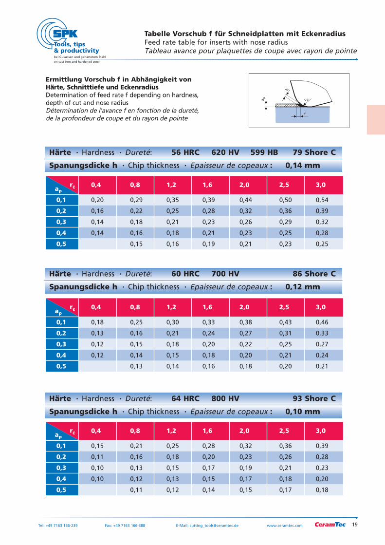
Härte Hardness Dureté: 56 HRC 620 HV 599 HB 79 Shore C
Spanungsdicke h Chip thickness Epaisseur de copeaux : 0,14 mm
Härte Hardness Dureté: 60 HRC 700 HV 86 Shore C
Spanungsdicke h Chip thickness Epaisseur de copeaux : 0,12 mm
Härte Hardness Dureté: 64 HRC 800 HV 93 Shore C
Spanungsdicke h Chip thickness Epaisseur de copeaux : 0,10 mm
rεεap0,4 0,8 1,2 1,6 2,0 2,5 3,0
0,1 0,15 0,21 0,25 0,28 0,32 0,36 0,39
0,2 0,11 0,16 0,18 0,20 0,23 0,26 0,28
0,3 0,10 0,13 0,15 0,17 0,19 0,21 0,23
0,4 0,10 0,12 0,13 0,15 0,17 0,18 0,20
0,5 0,11 0,12 0,14 0,15 0,17 0,18
rεεap0,4 0,8 1,2 1,6 2,0 2,5 3,0
0,1 0,18 0,25 0,30 0,33 0,38 0,43 0,46
0,2 0,13 0,16 0,21 0,24 0,27 0,31 0,33
0,3 0,12 0,15 0,18 0,20 0,22 0,25 0,27
0,4 0,12 0,14 0,15 0,18 0,20 0,21 0,24
0,5 0,13 0,14 0,16 0,18 0,20 0,21
rεεap0,4 0,8 1,2 1,6 2,0 2,5 3,0
0,1 0,20 0,29 0,35 0,39 0,44 0,50 0,54
0,2 0,16 0,22 0,25 0,28 0,32 0,36 0,39
0,3 0,14 0,18 0,21 0,23 0,26 0,29 0,32
0,4 0,14 0,16 0,18 0,21 0,23 0,25 0,28
0,5 0,15 0,16 0,19 0,21 0,23 0,25
Tabelle Vorschub f für Schneidplatten mit EckenradiusFeed rate table for inserts with nose radiusTableau avance pour plaquettes de coupe avec rayon de pointe
Ermittlung Vorschub f in Abhängigkeit von Härte, Schnitttiefe und EckenradiusDetermination of feed rate f depending on hardness,depth of cut and nose radiusDétermination de l'avance f en fonction de la dureté,de la profondeur de coupe et du rayon de pointe
20
bei Gusseisen und gehärtetem Stahl
on cast iron and hardened steel
Tel: +49 7163 166-239 Fax: +49 7163 166-388 E-Mail: [email protected] www.ceramtec.com
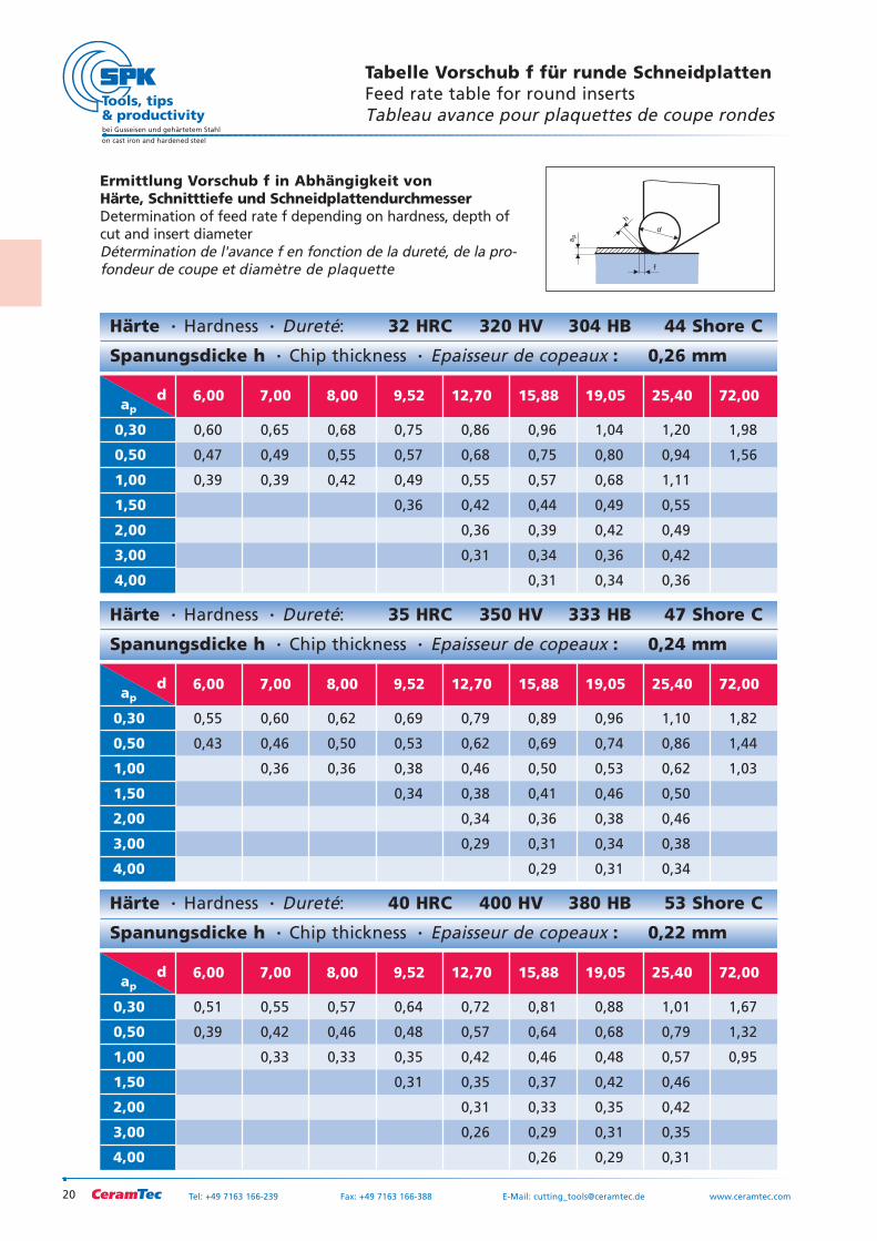
Tabelle Vorschub f für runde SchneidplattenFeed rate table for round insertsTableau avance pour plaquettes de coupe rondes
Ermittlung Vorschub f in Abhängigkeit von Härte, Schnitttiefe und SchneidplattendurchmesserDetermination of feed rate f depending on hardness, depth ofcut and insert diameterDétermination de l'avance f en fonction de la dureté, de la pro-fondeur de coupe et diamètre de plaquette
Härte Hardness Dureté: 40 HRC 400 HV 380 HB 53 Shore C
Spanungsdicke h Chip thickness Epaisseur de copeaux : 0,22 mm
d ap
6,00 7,00 8,00 9,52 12,70 15,88 19,05 25,40 72,00
0,30 0,51 0,55 0,57 0,64 0,72 0,81 0,88 1,01 1,67
0,50 0,39 0,42 0,46 0,48 0,57 0,64 0,68 0,79 1,32
1,00 0,33 0,33 0,35 0,42 0,46 0,48 0,57 0,95
1,50 0,31 0,35 0,37 0,42 0,46
2,00 0,31 0,33 0,35 0,42
3,00 0,26 0,29 0,31 0,35
4,00 0,26 0,29 0,31
Härte Hardness Dureté: 32 HRC 320 HV 304 HB 44 Shore C
Spanungsdicke h Chip thickness Epaisseur de copeaux : 0,26 mm
d ap
6,00 7,00 8,00 9,52 12,70 15,88 19,05 25,40 72,00
0,30 0,60 0,65 0,68 0,75 0,86 0,96 1,04 1,20 1,98
0,50 0,47 0,49 0,55 0,57 0,68 0,75 0,80 0,94 1,56
1,00 0,39 0,39 0,42 0,49 0,55 0,57 0,68 1,11
1,50 0,36 0,42 0,44 0,49 0,55
2,00 0,36 0,39 0,42 0,49
3,00 0,31 0,34 0,36 0,42
4,00 0,31 0,34 0,36
Härte Hardness Dureté: 35 HRC 350 HV 333 HB 47 Shore C
Spanungsdicke h Chip thickness Epaisseur de copeaux : 0,24 mm
d ap
6,00 7,00 8,00 9,52 12,70 15,88 19,05 25,40 72,00
0,30 0,55 0,60 0,62 0,69 0,79 0,89 0,96 1,10 1,82
0,50 0,43 0,46 0,50 0,53 0,62 0,69 0,74 0,86 1,44
1,00 0,36 0,36 0,38 0,46 0,50 0,53 0,62 1,03
1,50 0,34 0,38 0,41 0,46 0,50
2,00 0,34 0,36 0,38 0,46
3,00 0,29 0,31 0,34 0,38
4,00 0,29 0,31 0,34
ap
f
d
h
21
bei Gusseisen und gehärtetem Stahl
on cast iron and hardened steel
Tel: +49 7163 166-239 Fax: +49 7163 166-388 E-Mail: [email protected] www.ceramtec.com
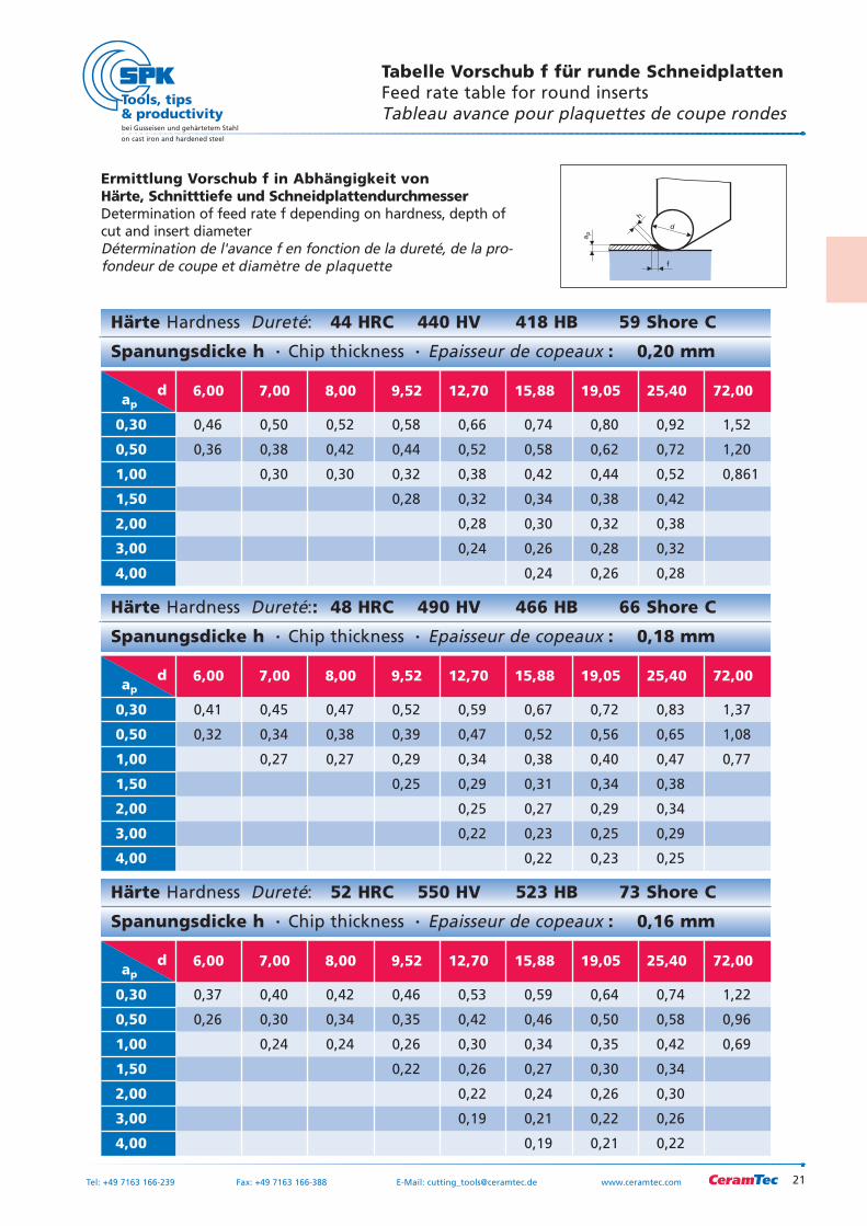
Härte Hardness Dureté: 44 HRC 440 HV 418 HB 59 Shore C
Spanungsdicke h Chip thickness Epaisseur de copeaux : 0,20 mm
d ap
6,00 7,00 8,00 9,52 12,70 15,88 19,05 25,40 72,00
0,30 0,46 0,50 0,52 0,58 0,66 0,74 0,80 0,92 1,52
0,50 0,36 0,38 0,42 0,44 0,52 0,58 0,62 0,72 1,20
1,00 0,30 0,30 0,32 0,38 0,42 0,44 0,52 0,861
1,50 0,28 0,32 0,34 0,38 0,42
2,00 0,28 0,30 0,32 0,38
3,00 0,24 0,26 0,28 0,32
4,00 0,24 0,26 0,28
Härte Hardness Dureté:: 48 HRC 490 HV 466 HB 66 Shore C
Spanungsdicke h Chip thickness Epaisseur de copeaux : 0,18 mm
d ap
6,00 7,00 8,00 9,52 12,70 15,88 19,05 25,40 72,00
0,30 0,41 0,45 0,47 0,52 0,59 0,67 0,72 0,83 1,37
0,50 0,32 0,34 0,38 0,39 0,47 0,52 0,56 0,65 1,08
1,00 0,27 0,27 0,29 0,34 0,38 0,40 0,47 0,77
1,50 0,25 0,29 0,31 0,34 0,38
2,00 0,25 0,27 0,29 0,34
3,00 0,22 0,23 0,25 0,29
4,00 0,22 0,23 0,25
Härte Hardness Dureté: 52 HRC 550 HV 523 HB 73 Shore C
Spanungsdicke h Chip thickness Epaisseur de copeaux : 0,16 mm
d ap
6,00 7,00 8,00 9,52 12,70 15,88 19,05 25,40 72,00
0,30 0,37 0,40 0,42 0,46 0,53 0,59 0,64 0,74 1,22
0,50 0,26 0,30 0,34 0,35 0,42 0,46 0,50 0,58 0,96
1,00 0,24 0,24 0,26 0,30 0,34 0,35 0,42 0,69
1,50 0,22 0,26 0,27 0,30 0,34
2,00 0,22 0,24 0,26 0,30
3,00 0,19 0,21 0,22 0,26
4,00 0,19 0,21 0,22
Ermittlung Vorschub f in Abhängigkeit von Härte, Schnitttiefe und SchneidplattendurchmesserDetermination of feed rate f depending on hardness, depth ofcut and insert diameterDétermination de l'avance f en fonction de la dureté, de la pro-fondeur de coupe et diamètre de plaquette
ap
f
d
h
Tabelle Vorschub f für runde SchneidplattenFeed rate table for round insertsTableau avance pour plaquettes de coupe rondes
22
bei Gusseisen und gehärtetem Stahl
on cast iron and hardened steel
Tel: +49 7163 166-239 Fax: +49 7163 166-388 E-Mail: [email protected] www.ceramtec.com
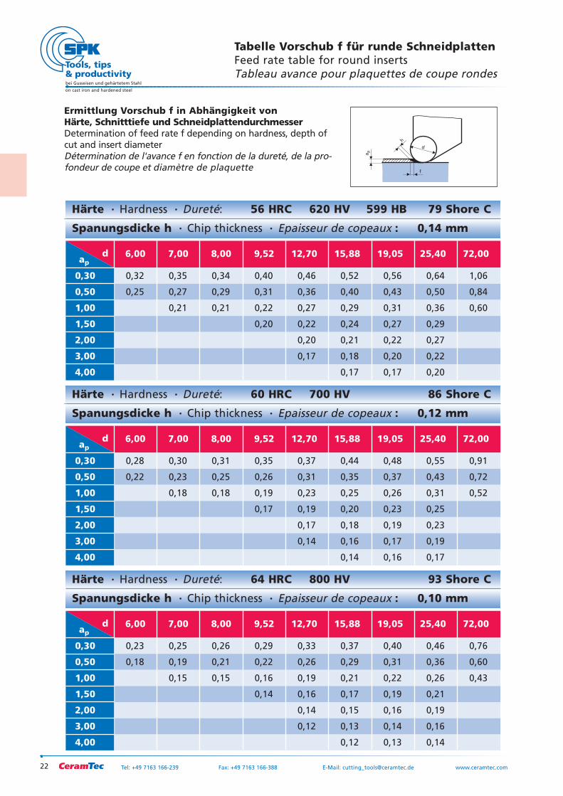
Härte Hardness Dureté: 56 HRC 620 HV 599 HB 79 Shore C
Spanungsdicke h Chip thickness Epaisseur de copeaux : 0,14 mm
d ap
6,00 7,00 8,00 9,52 12,70 15,88 19,05 25,40 72,00
0,30 0,32 0,35 0,34 0,40 0,46 0,52 0,56 0,64 1,06
0,50 0,25 0,27 0,29 0,31 0,36 0,40 0,43 0,50 0,84
1,00 0,21 0,21 0,22 0,27 0,29 0,31 0,36 0,60
1,50 0,20 0,22 0,24 0,27 0,29
2,00 0,20 0,21 0,22 0,27
3,00 0,17 0,18 0,20 0,22
4,00 0,17 0,17 0,20
Härte Hardness Dureté: 60 HRC 700 HV 86 Shore C
Spanungsdicke h Chip thickness Epaisseur de copeaux : 0,12 mm
d ap
6,00 7,00 8,00 9,52 12,70 15,88 19,05 25,40 72,00
0,30 0,28 0,30 0,31 0,35 0,37 0,44 0,48 0,55 0,91
0,50 0,22 0,23 0,25 0,26 0,31 0,35 0,37 0,43 0,72
1,00 0,18 0,18 0,19 0,23 0,25 0,26 0,31 0,52
1,50 0,17 0,19 0,20 0,23 0,25
2,00 0,17 0,18 0,19 0,23
3,00 0,14 0,16 0,17 0,19
4,00 0,14 0,16 0,17
Härte Hardness Dureté: 64 HRC 800 HV 93 Shore C
Spanungsdicke h Chip thickness Epaisseur de copeaux : 0,10 mm
d ap
6,00 7,00 8,00 9,52 12,70 15,88 19,05 25,40 72,00
0,30 0,23 0,25 0,26 0,29 0,33 0,37 0,40 0,46 0,76
0,50 0,18 0,19 0,21 0,22 0,26 0,29 0,31 0,36 0,60
1,00 0,15 0,15 0,16 0,19 0,21 0,22 0,26 0,43
1,50 0,14 0,16 0,17 0,19 0,21
2,00 0,14 0,15 0,16 0,19
3,00 0,12 0,13 0,14 0,16
4,00 0,12 0,13 0,14
Ermittlung Vorschub f in Abhängigkeit von Härte, Schnitttiefe und SchneidplattendurchmesserDetermination of feed rate f depending on hardness, depth ofcut and insert diameterDétermination de l'avance f en fonction de la dureté, de la pro-fondeur de coupe et diamètre de plaquette
ap
f
d
h
Tabelle Vorschub f für runde SchneidplattenFeed rate table for round insertsTableau avance pour plaquettes de coupe rondes
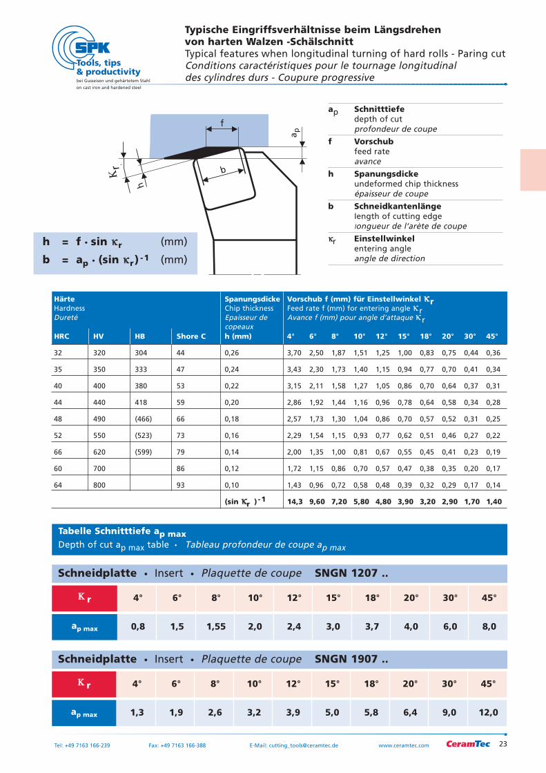
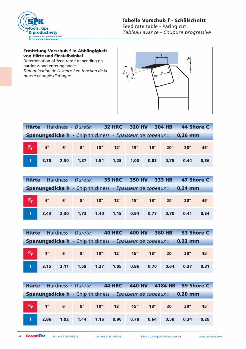
ap Schnitttiefedepth of cutprofondeur de coupe
f Vorschubfeed rateavance
h Spanungsdickeundeformed chip thicknessépaisseur de coupe
b SchneidkantenlängeIength of cutting edgelongueur de l‘arète de coupe
κκr Einstellwinkelentering angleangle de direction
Typische Eingriffsverhältnisse beim Längsdrehen von harten Walzen -SchälschnittTypical features when longitudinal turning of hard rolls - Paring cutConditions caractéristiques pour le tournage longitudinal des cylindres durs - Coupure progressive
23
bei Gusseisen und gehärtetem Stahl
on cast iron and hardened steel
Tel: +49 7163 166-239 Fax: +49 7163 166-388 E-Mail: [email protected] www.ceramtec.com
Schneidplatte Insert Plaquette de coupe SNGN 1207 ..
ΚΚ r 4° 6° 8° 10° 12° 15° 18° 20° 30° 45°
ap max 0,8 1,5 1,55 2,0 2,4 3,0 3,7 4,0 6,0 8,0
Schneidplatte Insert Plaquette de coupe SNGN 1907 ..
ΚΚ r 4° 6° 8° 10° 12° 15° 18° 20° 30° 45°
ap max 1,3 1,9 2,6 3,2 3,9 5,0 5,8 6,4 9,0 12,0
ap
b
f
h
�r
h = f sin κκr (mm)
b = ap (sin κκr) -1 (mm)
Κr
Tabelle Schnitttiefe ap maxDepth of cut ap max table Tableau profondeur de coupe ap max
Härte Spanungsdicke Vorschub f (mm) für Einstellwinkel κκrHardness Chip thickness Feed rate f (mm) for entering angle κ rDureté Epaisseur de Avance f (mm) pour angle d’attaque κ r
copeauxHRC HV HB Shore C h (mm) 4° 6° 8° 10° 12° 15° 18° 20° 30° 45°
32 320 304 44 0,26 3,70 2,50 1,87 1,51 1,25 1,00 0,83 0,75 0,44 0,36
35 350 333 47 0,24 3,43 2,30 1,73 1,40 1,15 0,94 0,77 0,70 0,41 0,34
40 400 380 53 0,22 3,15 2,11 1,58 1,27 1,05 0,86 0,70 0,64 0,37 0,31
44 440 418 59 0,20 2,86 1,92 1,44 1,16 0,96 0,78 0,64 0,58 0,34 0,28
48 490 (466) 66 0,18 2,57 1,73 1,30 1,04 0,86 0,70 0,57 0,52 0,31 0,25
52 550 (523) 73 0,16 2,29 1,54 1,15 0,93 0,77 0,62 0,51 0,46 0,27 0,22
66 620 (599) 79 0,14 2,00 1,35 1,00 0,81 0,67 0,55 0,45 0,41 0,23 0,19
60 700 86 0,12 1,72 1,15 0,86 0,70 0,57 0,47 0,38 0,35 0,20 0,17
64 800 93 0,10 1,43 0,96 0,72 0,58 0,48 0,39 0,32 0,29 0,17 0,14
(sin κκr ) -1 14,3 9,60 7,20 5,80 4,80 3,90 3,20 2,90 1,70 1,40
24
bei Gusseisen und gehärtetem Stahl
on cast iron and hardened steel
Tel: +49 7163 166-239 Fax: +49 7163 166-388 E-Mail: [email protected] www.ceramtec.com
Tabelle Vorschub f - SchälschnittFeed rate table - Paring cutTableau avance - Coupure progressive
Ermittlung Vorschub f in Abhängigkeitvon Härte und EinstellwinkelDetermination of feed rate f depending onhardness and entering angle Détermination de l'avance f en fonction de ladureté et angle d’attaque
Härte Hardness Dureté: 32 HRC 320 HV 304 HB 44 Shore C
Spanungsdicke h Chip thickness Epaisseur de copeaux : 0,26 mm
ap
b
f
h
�r
ΚΚr 4° 6° 8° 10° 12° 15° 18° 20° 30° 45°
f 3,70 2,50 1,87 1,51 1,25 1,00 0,83 0,75 0,44 0,36
Härte Hardness Dureté: 35 HRC 350 HV 333 HB 47 Shore C
Spanungsdicke h Chip thickness Epaisseur de copeaux : 0,24 mm
ΚΚr 4° 6° 8° 10° 12° 15° 18° 20° 30° 45°
f 3,43 2,30 1,73 1,40 1,15 0,94 0,77 0,70 0,41 0,34
Härte Hardness Dureté: 40 HRC 400 HV 380 HB 53 Shore C
Spanungsdicke h Chip thickness Epaisseur de copeaux : 0,22 mm
ΚΚr 4° 6° 8° 10° 12° 15° 18° 20° 30° 45°
f 3,15 2,11 1,58 1,27 1,05 0,86 0,70 0,64 0,37 0,31
Härte Hardness Dureté: 44 HRC 440 HV 4184 HB 59 Shore C
Spanungsdicke h Chip thickness Epaisseur de copeaux : 0,20 mm
ΚΚr 4° 6° 8° 10° 12° 15° 18° 20° 30° 45°
f 2,86 1,92 1,44 1,16 0,96 0,78 0,64 0,58 0,34 0,28
25
bei Gusseisen und gehärtetem Stahl
on cast iron and hardened steel
Tel: +49 7163 166-239 Fax: +49 7163 166-388 E-Mail: [email protected] www.ceramtec.com
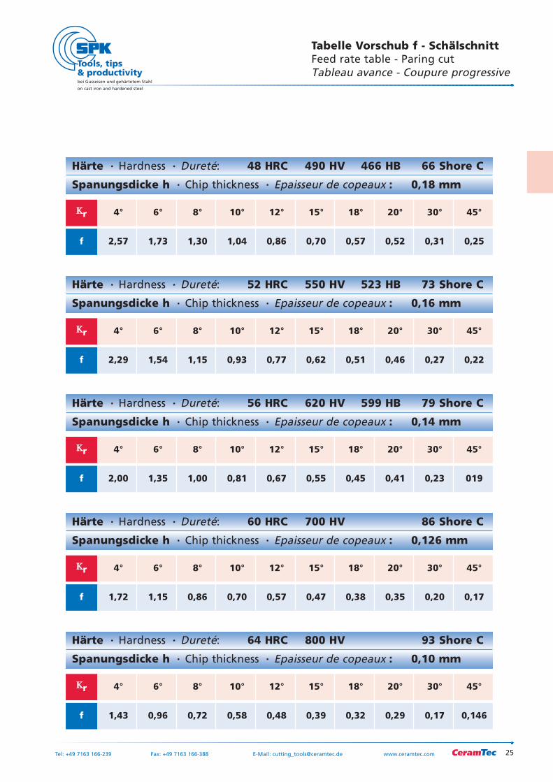
Tabelle Vorschub f - SchälschnittFeed rate table - Paring cutTableau avance - Coupure progressive
Härte Hardness Dureté: 52 HRC 550 HV 523 HB 73 Shore C
Spanungsdicke h Chip thickness Epaisseur de copeaux : 0,16 mm
ΚΚr 4° 6° 8° 10° 12° 15° 18° 20° 30° 45°
f 2,29 1,54 1,15 0,93 0,77 0,62 0,51 0,46 0,27 0,22
Härte Hardness Dureté: 48 HRC 490 HV 466 HB 66 Shore C
Spanungsdicke h Chip thickness Epaisseur de copeaux : 0,18 mm
ΚΚr 4° 6° 8° 10° 12° 15° 18° 20° 30° 45°
f 2,57 1,73 1,30 1,04 0,86 0,70 0,57 0,52 0,31 0,25
Härte Hardness Dureté: 56 HRC 620 HV 599 HB 79 Shore C
Spanungsdicke h Chip thickness Epaisseur de copeaux : 0,14 mm
ΚΚr 4° 6° 8° 10° 12° 15° 18° 20° 30° 45°
f 2,00 1,35 1,00 0,81 0,67 0,55 0,45 0,41 0,23 019
Härte Hardness Dureté: 60 HRC 700 HV 86 Shore C
Spanungsdicke h Chip thickness Epaisseur de copeaux : 0,126 mm
ΚΚr 4° 6° 8° 10° 12° 15° 18° 20° 30° 45°
f 1,72 1,15 0,86 0,70 0,57 0,47 0,38 0,35 0,20 0,17
Härte Hardness Dureté: 64 HRC 800 HV 93 Shore C
Spanungsdicke h Chip thickness Epaisseur de copeaux : 0,10 mm
ΚΚr 4° 6° 8° 10° 12° 15° 18° 20° 30° 45°
f 1,43 0,96 0,72 0,58 0,48 0,39 0,32 0,29 0,17 0,146
26
bei Gusseisen und gehärtetem Stahl
on cast iron and hardened steel
Tel: +49 7163 166-239 Fax: +49 7163 166-388 E-Mail: [email protected] www.ceramtec.com
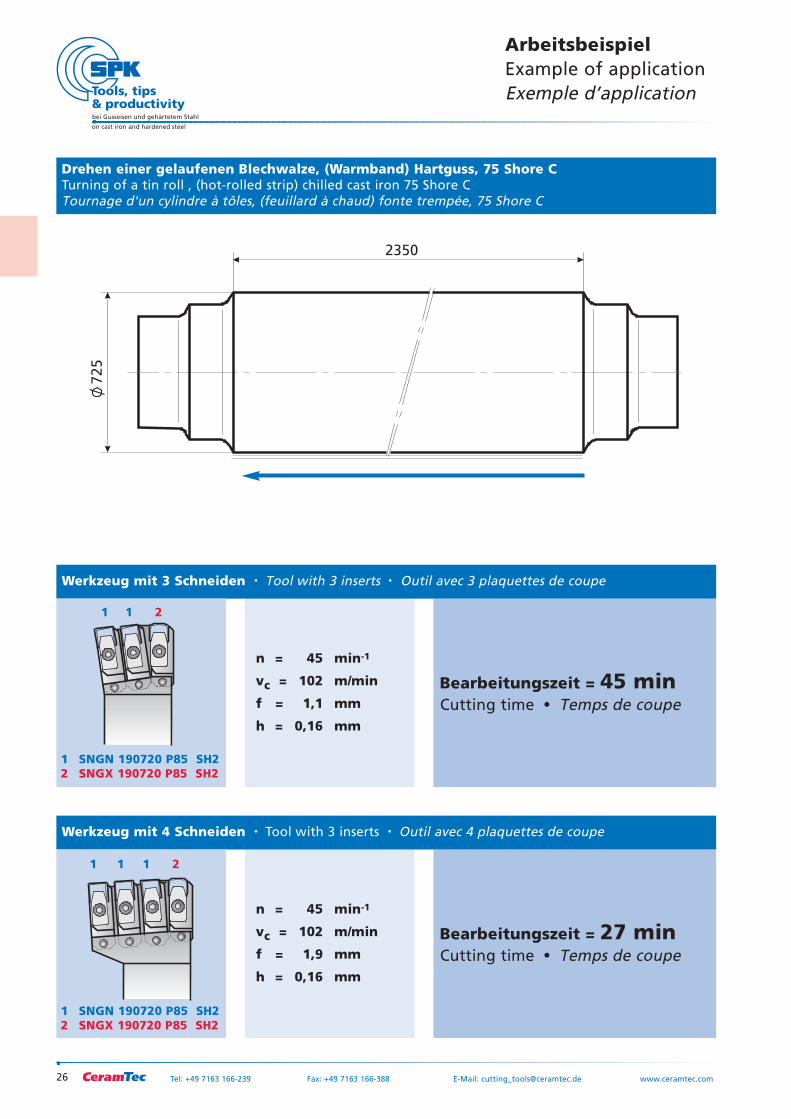
n = 45 min-1
vc = 102 m/min
f = 1,1 mm
h = 0,16 mm
Bearbeitungszeit = 45 minCutting time Temps de coupe
n = 45 min-1
vc = 102 m/min
f = 1,9 mm
h = 0,16 mm
Bearbeitungszeit = 27 minCutting time Temps de coupe
2350
725
Drehen einer gelaufenen Blechwalze, (Warmband) Hartguss, 75 Shore CTurning of a tin roll , (hot-rolled strip) chilled cast iron 75 Shore CTournage d'un cylindre à tôles, (feuillard à chaud) fonte trempée, 75 Shore C
Werkzeug mit 3 Schneiden Tool with 3 inserts Outil avec 3 plaquettes de coupe
Werkzeug mit 4 Schneiden Tool with 3 inserts Outil avec 4 plaquettes de coupe
ArbeitsbeispielExample of applicationExemple d’application
1 SNGN 190720 P85 SH22 SNGX 190720 P85 SH2
1 1 2
1 SNGN 190720 P85 SH22 SNGX 190720 P85 SH2
11 1 2
27
bei Gusseisen und gehärtetem Stahl
on cast iron and hardened steel
Tel: +49 7163 166-239 Fax: +49 7163 166-388 E-Mail: [email protected] www.ceramtec.com
21
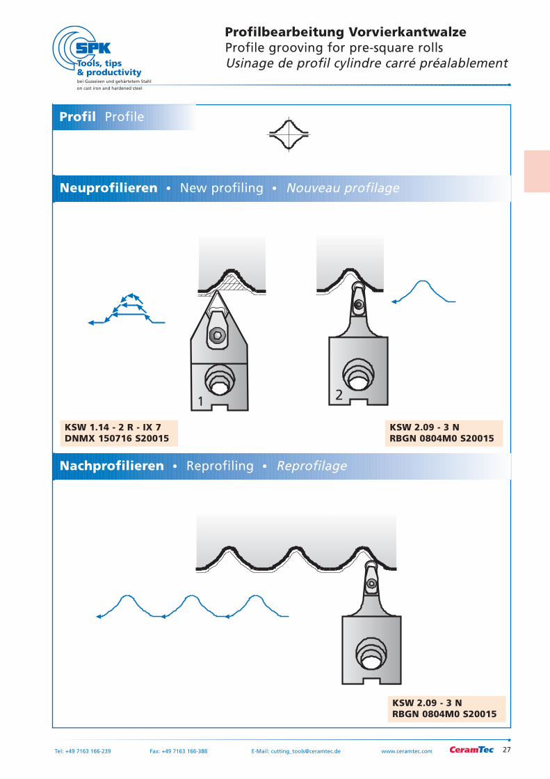
Profilbearbeitung VorvierkantwalzeProfile grooving for pre-square rollsUsinage de profil cylindre carré préalablement
KSW 2.09 - 3 NRBGN 0804M0 S20015
KSW 2.09 - 3 NRBGN 0804M0 S20015
KSW 1.14 - 2 R - IX 7DNMX 150716 S20015
Neuprofilieren New profiling Nouveau profilage
Profil Profile
Nachprofilieren Reprofiling Reprofilage
28
bei Gusseisen und gehärtetem Stahl
on cast iron and hardened steel
Tel: +49 7163 166-239 Fax: +49 7163 166-388 E-Mail: [email protected] www.ceramtec.com
1 2
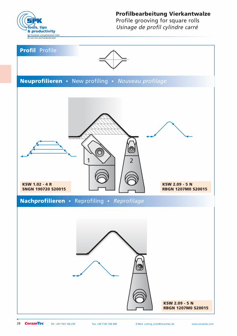
Profilbearbeitung VierkantwalzeProfile grooving for square rollsUsinage de profil cylindre carré
KSW 2.09 - 5 NRBGN 1207M0 S20015
KSW 2.09 - 5 NRBGN 1207M0 S20015
KSW 1.02 - 4 RSNGN 190720 S20015
Neuprofilieren New profiling Nouveau profilage
Profil Profile
Nachprofilieren Reprofiling Reprofilage
29
bei Gusseisen und gehärtetem Stahl
on cast iron and hardened steel
Tel: +49 7163 166-239 Fax: +49 7163 166-388 E-Mail: [email protected] www.ceramtec.com
1 2
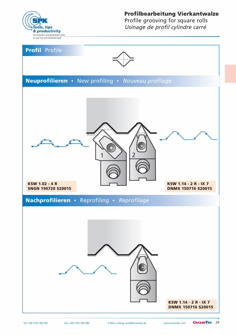
Profilbearbeitung VierkantwalzeProfile grooving for square rollsUsinage de profil cylindre carré
KSW 1.14 - 2 R - IX 7DNMX 150716 S20015
KSW 1.14 - 2 R - IX 7DNMX 150716 S20015
KSW 1.02 - 4 RSNGN 190720 S20015
Neuprofilieren New profiling Nouveau profilage
Profil Profile
Nachprofilieren Reprofiling Reprofilage
30
bei Gusseisen und gehärtetem Stahl
on cast iron and hardened steel
Tel: +49 7163 166-239 Fax: +49 7163 166-388 E-Mail: [email protected] www.ceramtec.com
1 2
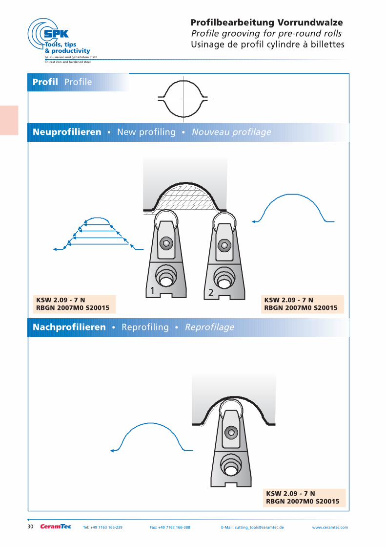
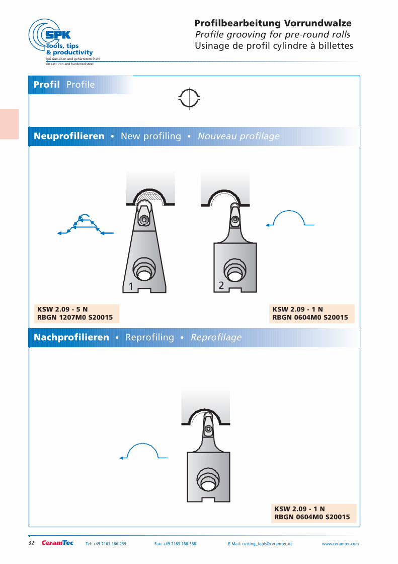
Profilbearbeitung VorrundwalzeProfile grooving for pre-round rollsUsinage de profil cylindre à billettes
KSW 2.09 - 7 NRBGN 2007M0 S20015
KSW 2.09 - 7 NRBGN 2007M0 S20015
KSW 2.09 - 7 NRBGN 2007M0 S20015
Neuprofilieren New profiling Nouveau profilage
Profil Profile
Nachprofilieren Reprofiling Reprofilage
31
bei Gusseisen und gehärtetem Stahl
on cast iron and hardened steel
Tel: +49 7163 166-239 Fax: +49 7163 166-388 E-Mail: [email protected] www.ceramtec.com
1 2
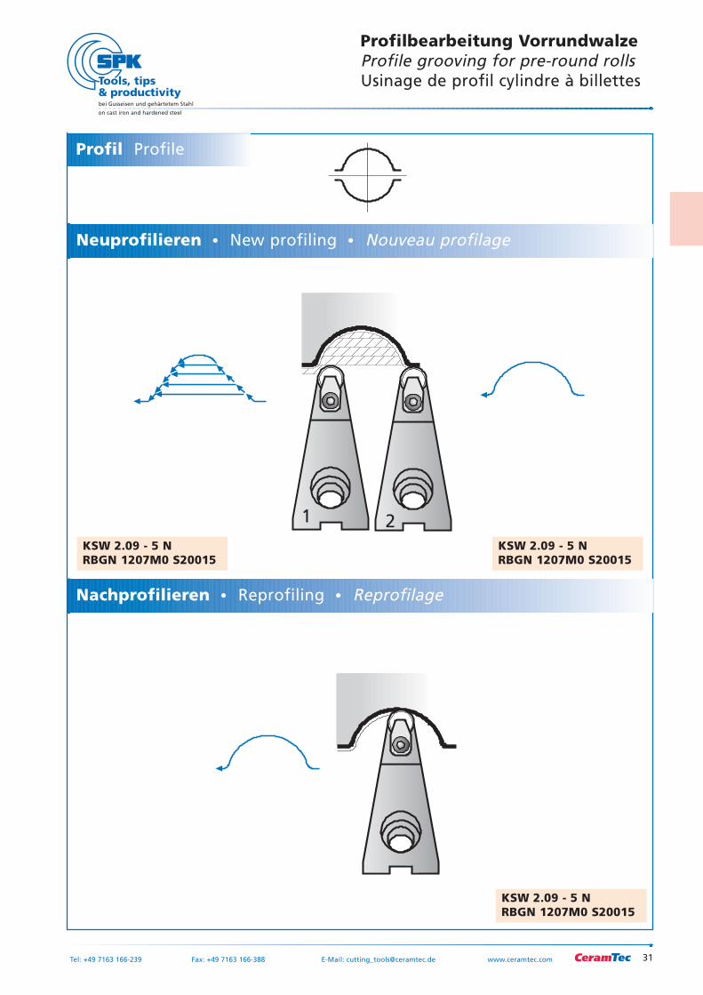
Profilbearbeitung VorrundwalzeProfile grooving for pre-round rollsUsinage de profil cylindre à billettes
KSW 2.09 - 5 NRBGN 1207M0 S20015
KSW 2.09 - 5 NRBGN 1207M0 S20015
KSW 2.09 - 5 NRBGN 1207M0 S20015
Neuprofilieren New profiling Nouveau profilage
Profil Profile
Nachprofilieren Reprofiling Reprofilage
32
bei Gusseisen und gehärtetem Stahl
on cast iron and hardened steel
Tel: +49 7163 166-239 Fax: +49 7163 166-388 E-Mail: [email protected] www.ceramtec.com
21
Profilbearbeitung VorrundwalzeProfile grooving for pre-round rollsUsinage de profil cylindre à billettes
KSW 2.09 - 1 NRBGN 0604M0 S20015
KSW 2.09 - 1 NRBGN 0604M0 S20015
KSW 2.09 - 5 NRBGN 1207M0 S20015
Neuprofilieren New profiling Nouveau profilage
Profil Profile
Nachprofilieren Reprofiling Reprofilage
33
bei Gusseisen und gehärtetem Stahl
on cast iron and hardened steel
Tel: +49 7163 166-239 Fax: +49 7163 166-388 E-Mail: [email protected] www.ceramtec.com
1 2
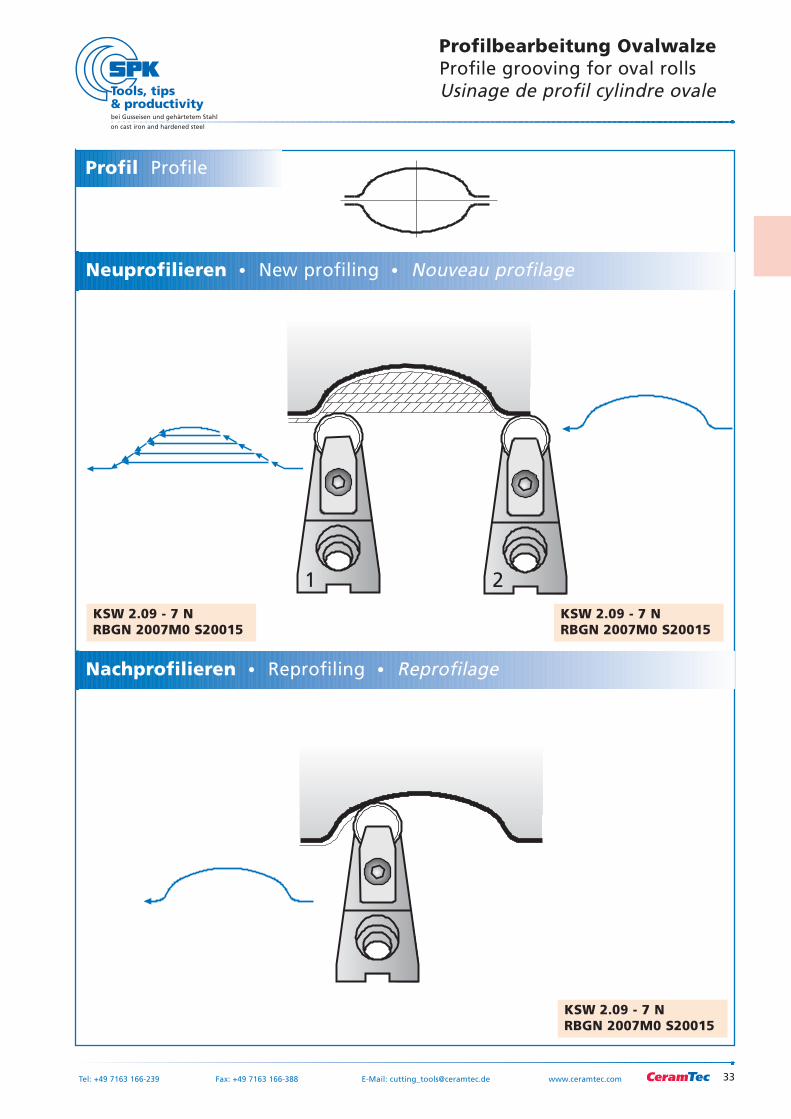
Profilbearbeitung OvalwalzeProfile grooving for oval rollsUsinage de profil cylindre ovale
KSW 2.09 - 7 NRBGN 2007M0 S20015
KSW 2.09 - 7 NRBGN 2007M0 S20015
KSW 2.09 - 7 NRBGN 2007M0 S20015
Neuprofilieren New profiling Nouveau profilage
Profil Profile
Nachprofilieren Reprofiling Reprofilage
34
bei Gusseisen und gehärtetem Stahl
on cast iron and hardened steel
Tel: +49 7163 166-239 Fax: +49 7163 166-388 E-Mail: [email protected] www.ceramtec.com
1 2
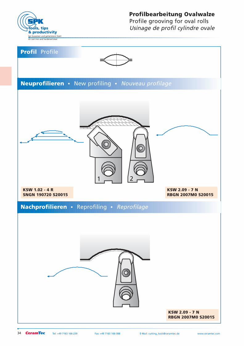
Profilbearbeitung OvalwalzeProfile grooving for oval rollsUsinage de profil cylindre ovale
KSW 2.09 - 7 NRBGN 2007M0 S20015
KSW 2.09 - 7 NRBGN 2007M0 S20015
KSW 1.02 - 4 RSNGN 190720 S20015
Neuprofilieren New profiling Nouveau profilage
Profil Profile
Nachprofilieren Reprofiling Reprofilage
35
bei Gusseisen und gehärtetem Stahl
on cast iron and hardened steel
Tel: +49 7163 166-239 Fax: +49 7163 166-388 E-Mail: [email protected] www.ceramtec.com
21
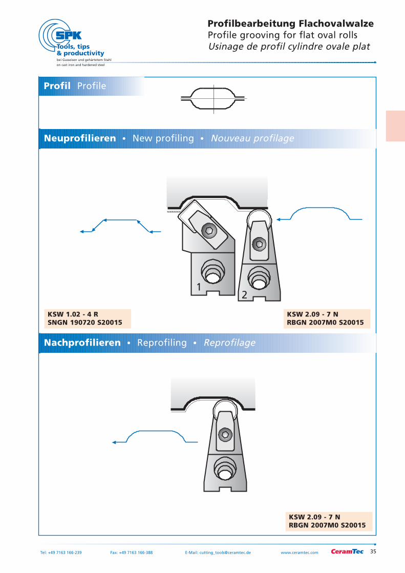
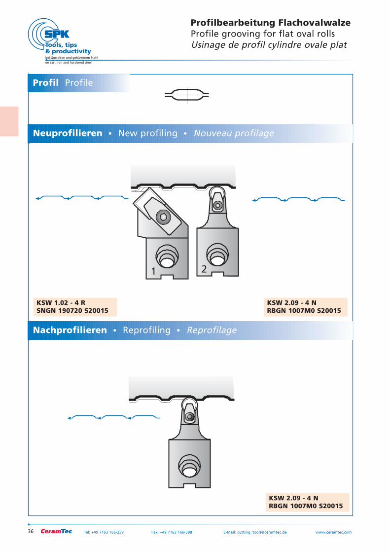
Profilbearbeitung FlachovalwalzeProfile grooving for flat oval rollsUsinage de profil cylindre ovale plat
KSW 2.09 - 7 NRBGN 2007M0 S20015
KSW 2.09 - 7 NRBGN 2007M0 S20015
KSW 1.02 - 4 RSNGN 190720 S20015
Neuprofilieren New profiling Nouveau profilage
Profil Profile
Nachprofilieren Reprofiling Reprofilage
36
bei Gusseisen und gehärtetem Stahl
on cast iron and hardened steel
Tel: +49 7163 166-239 Fax: +49 7163 166-388 E-Mail: [email protected] www.ceramtec.com
1 2
Profilbearbeitung FlachovalwalzeProfile grooving for flat oval rollsUsinage de profil cylindre ovale plat
KSW 2.09 - 4 NRBGN 1007M0 S20015
KSW 2.09 - 4 NRBGN 1007M0 S20015
KSW 1.02 - 4 RSNGN 190720 S20015
Neuprofilieren New profiling Nouveau profilage
Profil Profile
Nachprofilieren Reprofiling Reprofilage
SPK-Keramik-SchneidplattenSPK Ceramic inserts
Plaquettes de coupe céramique SPK
37Tel: +49 7163 166-239 Fax: +49 7163 166-388 E-Mail: [email protected] www.ceramtec.com
bei Gusseisen und gehärtetem Stahl
on cast iron and hardened steel
bei Gusseisen und gehärtetem Stahl
on cast iron and hardened steel
38 Tel: +49 7163 166-239 Fax: +49 7163 166-388 E-Mail: [email protected] www.ceramtec.com
d
Inkre
isIn
scri
bed
cir
cle
Cer
cle
insc
rit
dmm
25,40
19,05
15,88
12,70
9,52
6,35
5,56
3,97
0°
3°
5°
7°
11°
15°
20°
25°
30°
C80°
E75°
D55°
V35°
W80°
dmm
d mm
RC, RNS
RB(Typ MO)
T60°
d
O135°
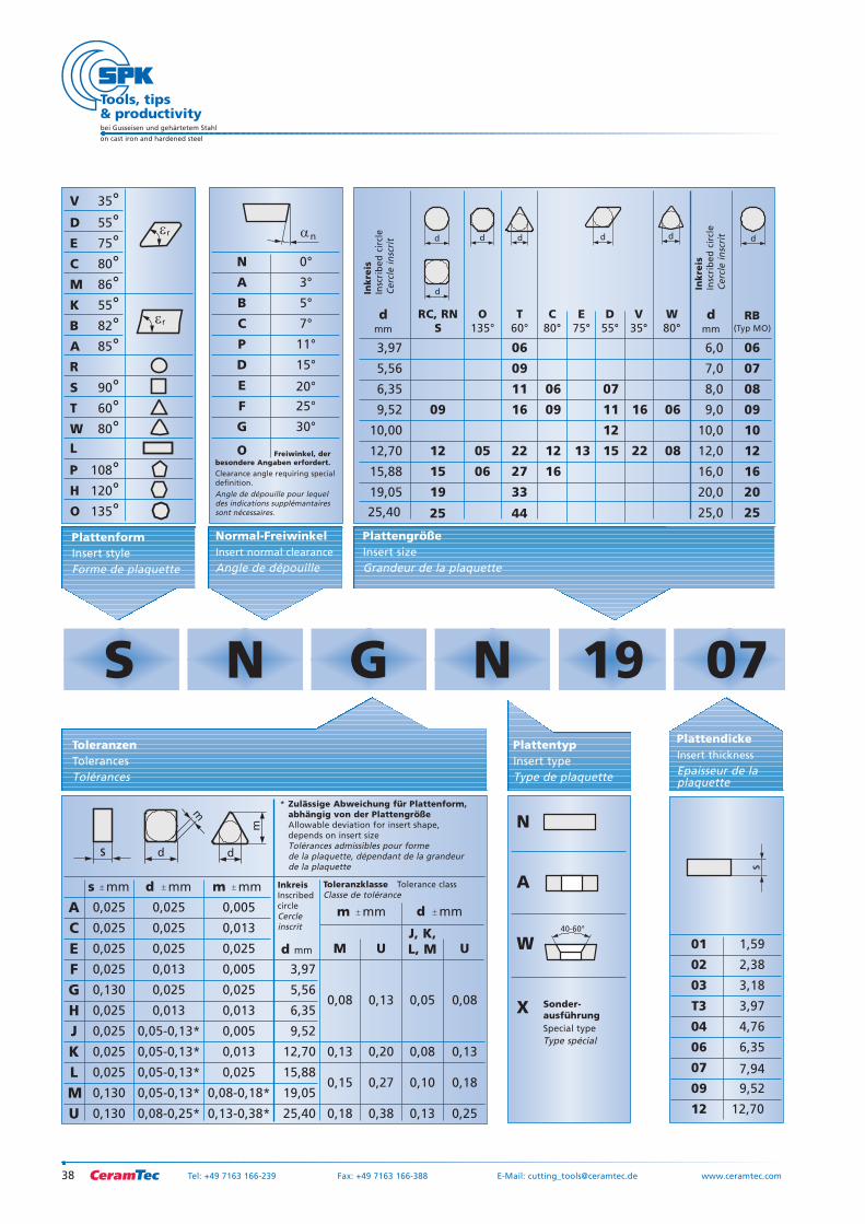
S N G N 19
V 35°D 55°E 75°C 80°M 86°K 55°B 82°A 85°R
S 90°T 60°W 80°L
P 108°H 120°O 135°
ToleranzenTolerancesTolérances
s
s mm d
A 0,025 0,025 0,005
C 0,025 0,025 0,013
E 0,025 0,025 0,025
F 0,025 0,013 0,005
G 0,130 0,025 0,025
H 0,025 0,013 0,013
J 0,025 0,05-0,13* 0,005
K 0,025 0,05-0,13* 0,013
L 0,025 0,05-0,13* 0,025
M 0,130 0,05-0,13* 0,08-0,18*
U 0,130 25,40 0,18 0,38 0,13 0,25
0,15 0,27 0,10 0,18
0,13 0,20 0,08 0,13
M UJ, K,L, M U
0,08 0,13 0,05 0,08
19,05
15,88
12,70
9,52
6,35
5,56
3,97
0,08-0,25* 0,13-0,38*
PlattengrößeInsert sizeGrandeur de la plaquette
20,0 20
25,0 25
16,0 16
12,0 12
10,0 10
9,0 09
8,0 08
7,0 07
6,0 06
25
19
15
12
09
44
33
27
22
06
05
16
11
09
06
16
12
09
06
13 15
10,00 12
22
11 16
08
06
07
Inkre
isIn
scri
bed
cir
cle
Cer
cle
insc
rit
InkreisInscribedcircleCercleinscrit
Toleranzklasse Tolerance classClasse de tolérance
d dd
d
d
N
A
B
C
P
D
E
F
G
Freiwinkel, derbesondere Angaben erfordert.
Clearance angle requiring specialdefinition.Angle de dépouille pour lequeldes indications supplémantairessont nécessaires.
Normal-FreiwinkelInsert normal clearance
Angle de dépouille
n
O
r
r
mm
d mm
m mm
m mm
m
d d
m
* Zulässige Abweichung für Plattenform,abhängig von der PlattengrößeAllowable deviation for insert shape,depends on insert size Tolérances admissibles pour forme de la plaquette, dépendant de la grandeurde la plaquette
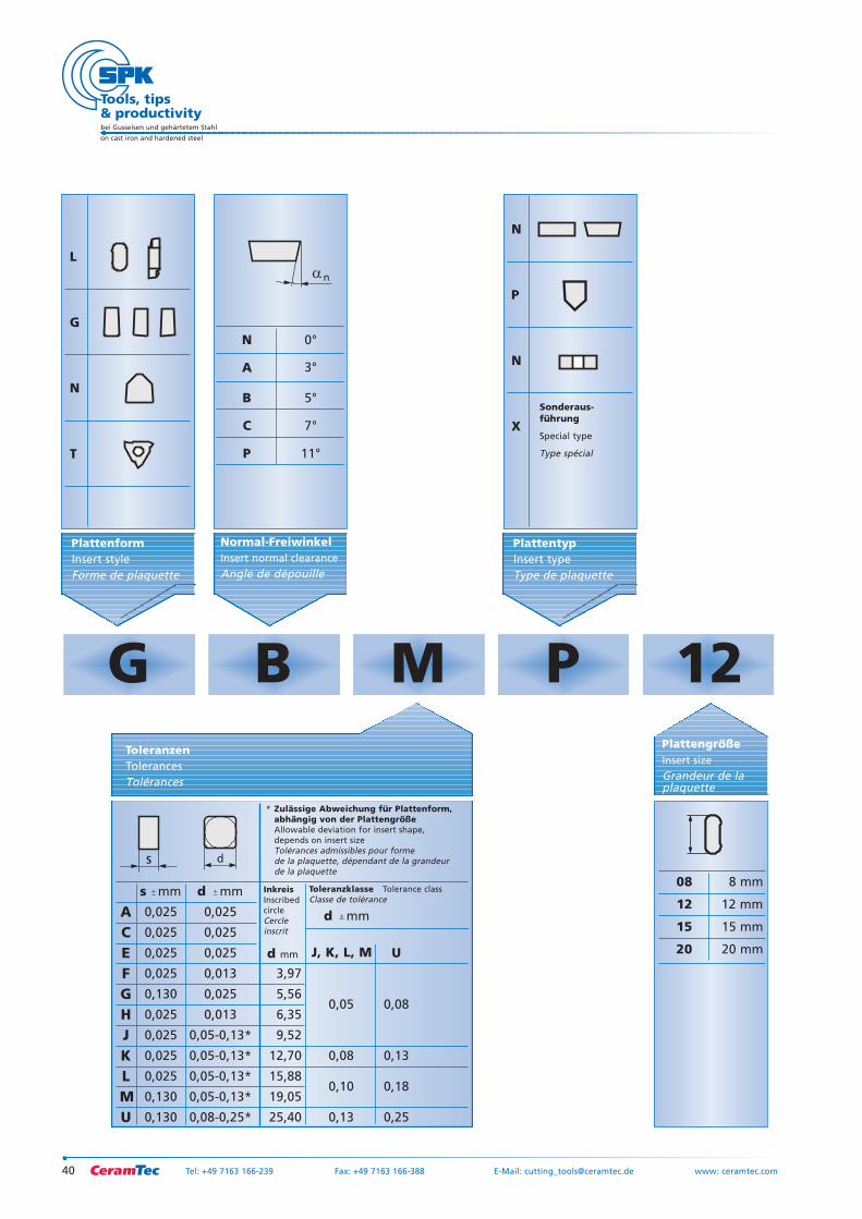
PlattentypInsert typeType de plaquette
N
A
40-60°
W
X Sonder-ausführungSpecial typeType spécial
PlattenformInsert styleForme de plaquette
07
1,59
2,38
3,18
3,97
4,76
6,35
7,94
9,52
12,70
01
02
03
T3
04
06
07
09
12
PlattendickeInsert thickness
Epaisseur de la plaquette
s
39Tel: +49 7163 166-239 Fax: +49 7163 166-388 E-Mail: [email protected] www.ceramtec.com
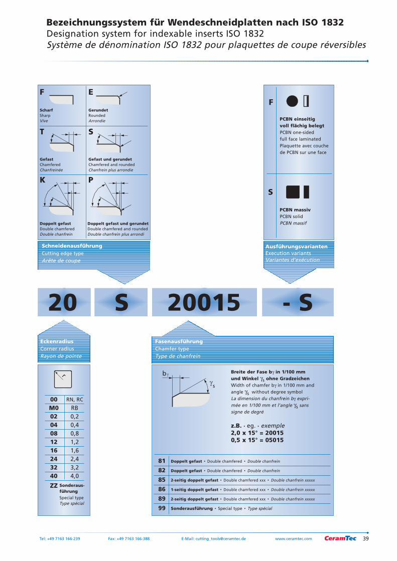
Bezeichnungssystem für Wendeschneidplatten nach ISO 1832Designation system for indexable inserts ISO 1832Système de dénomination ISO 1832 pour plaquettes de coupe réversibles
E
S
20 S - S20015EckenradiusCorner radiusRayon de pointe
ZZ
Doppelt gefast · Double chamfered · Double chanfrein
Doppelt gefast · Double chamfered · Double chanfrein
2-seitig doppelt gefast · Double chamfered xxx · Double chanfrein xxxxx
1-seitig doppelt gefast · Double chamfered xxx · Double chanfrein xxxxx
2-seitig doppelt gefast · Double chamfered xxx · Double chanfrein xxxxx
Sonderausführung · Special type · Type spécial
81
82
85
86
89
99
SchneidenausführungCutting edge type
Arête de coupe
Sonderaus-führungSpecial typeType spécial
FasenausführungChamfer typeType de chanfrein
Breite der Fase bγ in 1/100 mmund Winkel γs ohne GradzeichenWidth of chamfer bγ in 1/100 mm andangle γs without degree symbolLa dimension du chanfrein bγ expri-mée en 1/100 mm et l’angle γs sanssigne de degré
z.B. · eg. · exemple2,0 x 15° = 200150,5 x 15° = 05015
00 RN, RC
M0 RB02 0,204 0,408 0,812 1,216 1,624 2,432 3,240 4,0
r b
s
Doppelt gefast und gerundetDouble chamfered and roundedDouble chanfrein plus arrondi
GerundetRoundedArrondie
ScharfSharpVive
Gefast und gerundetChamfered and roundedChanfrein plus arrondie
GefastChamferedChanfreinée
Doppelt gefastDouble chamferedDouble chanfrein
K
T
F
P
AusführungsvariantenExecution variantsVariantes d’exécution
F
PCBN einseitig voll flächig belegtPCBN one-sided full face laminatedPlaquette avec couchede PCBN sur une face
S
PCBN massivPCBN solidPCBN massif
bei Gusseisen und gehärtetem Stahl
on cast iron and hardened steel
40 Tel: +49 7163 166-239 Fax: +49 7163 166-388 E-Mail: [email protected] www: ceramtec.com
0°
3°
5°
7°
11°
d mm
L
ToleranzenTolerancesTolérances
s
s mm d
A 0,025 0,025
C 0,025 0,025
E 0,025 0,025
F 0,025 0,013
G 0,130 0,025
H 0,025 0,013
J 0,025 0,05-0,13*
K 0,025 0,05-0,13*
L 0,025 0,05-0,13*
M 0,130 0,05-0,13*
U 0,130 25,40 0,13 0,25
0,10 0,18
0,08 0,13
J, K, L, M U
0,05 0,08
19,05
15,88
12,70
9,52
6,35
5,56
3,97
0,08-0,25*
InkreisInscribedcircleCercleinscrit
Toleranzklasse Tolerance classClasse de tolérance
N
A
B
C
P
Normal-FreiwinkelInsert normal clearance
Angle de dépouille
n
G
N
T
mm
d mm
d
* Zulässige Abweichung für Plattenform,abhängig von der PlattengrößeAllowable deviation for insert shape,depends on insert size Tolérances admissibles pour forme de la plaquette, dépendant de la grandeurde la plaquette
PlattenformInsert styleForme de plaquette
N
P
N
X
PlattentypInsert typeType de plaquette
G B M P 12
Sonderaus-führung
Special type
Type spécial
8 mm
12 mm
15 mm
20 mm
08
12
15
20
PlattengrößeInsert size
Grandeur de la plaquette
41Tel: +49 7163 166-239 Fax: +49 7163 166-388 E-Mail: [email protected] www: ceramtec.com
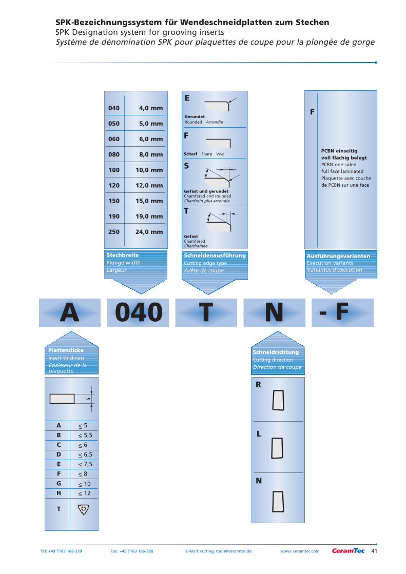
SPK-Bezeichnungssystem für Wendeschneidplatten zum StechenSPK Designation system for grooving insertsSystème de dénomination SPK pour plaquettes de coupe pour la plongée de gorge
040 4,0 mm
050 5,0 mm
060 6,0 mm
080 8,0 mm
100 10,0 mm
120 12,0 mm
150 15,0 mm
190 19,0 mm
250 24,0 mm
StechbreitePlunge widthLargeur
< 5
< 5,5
< 6
< 6,5
< 7,5
< 8
< 10
< 12
A
B
C
D
E
F
G
H
T
PlattendickeInsert thickness
Epaisseur de la plaquette
s
A 040 T N - F
N
R
L
SchneidrichtungCutting direction
Direction de coupe
E
S
SchneidenausführungCutting edge type
Arête de coupe
Gerundet Rounded Arrondie
Scharf Sharp Vive
Gefast und gerundetChamfered and roundedChanfrein plus arrondie
GefastChamferedChanfreinée
T
F
AusführungsvariantenExecution variantsVariantes d’exécution
F
PCBN einseitig voll flächig belegtPCBN one-sided full face laminatedPlaquette avec couchede PCBN sur une face
bei Gusseisen und gehärtetem Stahl
on cast iron and hardened steel
42 Tel: +49 7163 166-239 Fax: +49 7163 166-388 E-Mail: [email protected] www.ceramtec.com
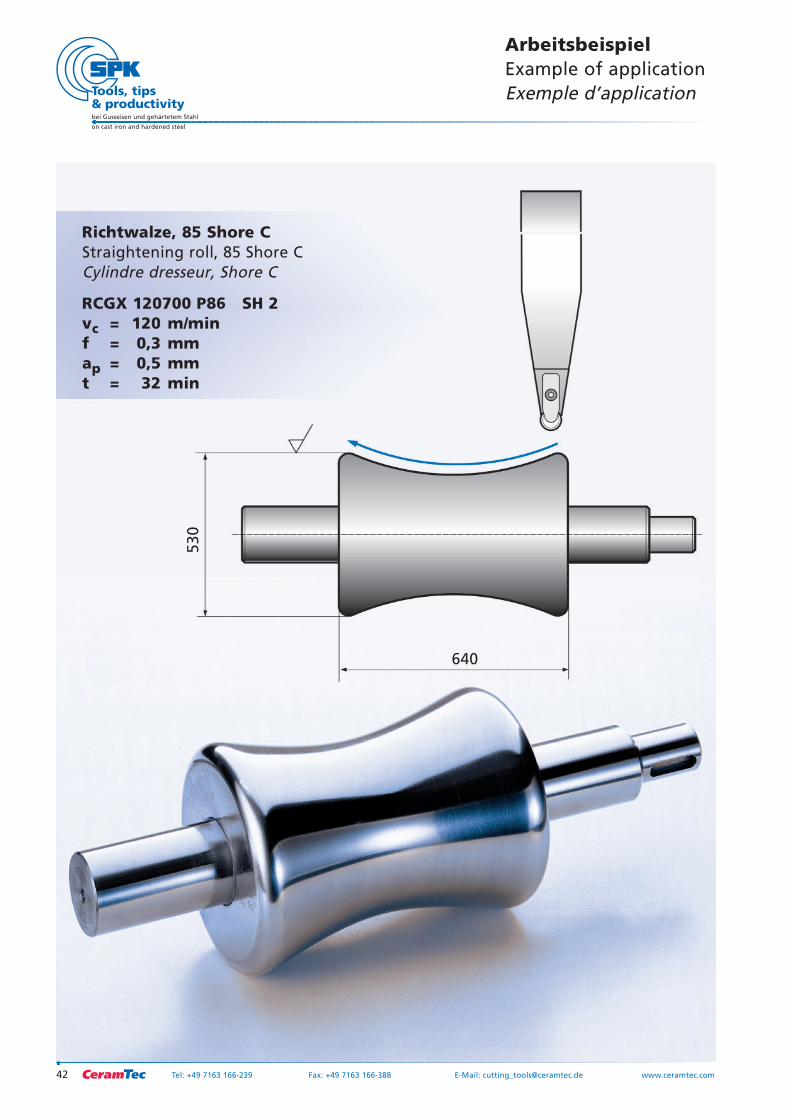
Richtwalze, 85 Shore CStraightening roll, 85 Shore CCylindre dresseur, Shore C
RCGX 120700 P86 SH 2vc = 120 m/minf = 0,3 mmap = 0,5 mmt = 32 min
ArbeitsbeispielExample of applicationExemple d’application
640
530
43Tel: +49 7163 166-239 Fax: +49 7163 166-388 E-Mail: [email protected] www.ceramtec.com
bei Gusseisen und gehärtetem Stahl
on cast iron and hardened steel
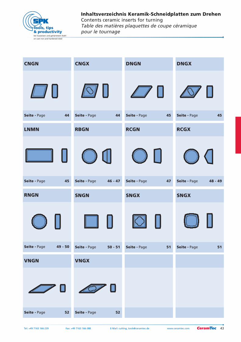
CNGN
Seite Page 44
CNGX
Seite Page 44
DNGN
Seite Page 45
DNGX
Seite Page 45
LNMN
Seite Page 45
SNGN
Seite Page 50 - 51
SNGX
Seite Page 51
SNGX
Seite Page 51
RBGN
Seite Page 46 - 47
RCGN
Seite Page 47
RCGX
Seite Page 48 - 49
RNGN
Seite Page 49 - 50
VNGN
Seite Page 52
VNGX
Seite Page 52
Inhaltsverzeichnis Keramik-Schneidplatten zum DrehenContents ceramic inserts for turningTable des matières plaquettes de coupe céramique pour le tournage
Schneidplatte ISO Sorte SPK-Best. Nr.Insert Grade SPK ref.no.Plaquette de coupe Nuance N° de réf. SPK
bei Gusseisen und gehärtetem Stahl
on cast iron and hardened steel
44
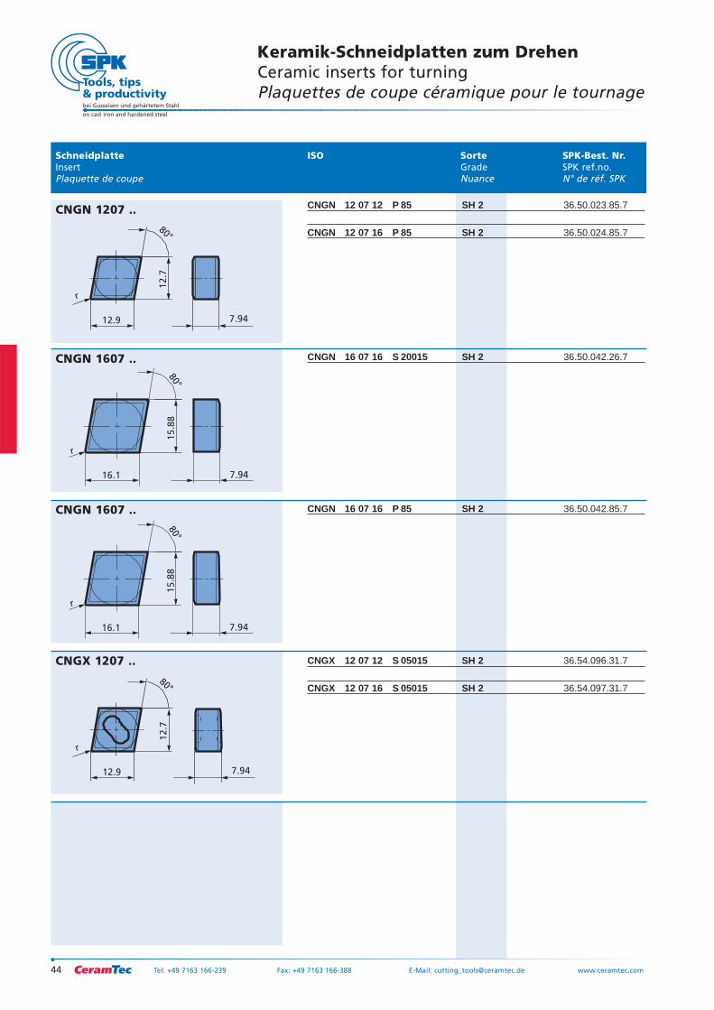
Keramik-Schneidplatten zum DrehenCeramic inserts for turningPlaquettes de coupe céramique pour le tournage
Tel: +49 7163 166-239 Fax: +49 7163 166-388 E-Mail: [email protected] www.ceramtec.com
CNGN 12 07 12 P 85 SH 2 36.50.023.85.7
CNGN 12 07 16 P 85 SH 2 36.50.024.85.7
CNGN 16 07 16 S 20015 SH 2 36.50.042.26.7
CNGN 16 07 16 P 85 SH 2 36.50.042.85.7
CNGX 12 07 12 S 05015 SH 2 36.54.096.31.7
CNGX 12 07 16 S 05015 SH 2 36.54.097.31.7
12.9
80°
12.7
r
7.94
CNGN 1207 ..
16.1
80°
15.8
8
r
7.94
CNGN 1607 ..
16.1
80°
15.8
8
r
7.94
CNGN 1607 ..
12.9
80°
12.7
r
7.94
CNGX 1207 ..
Schneidplatte ISO Sorte SPK-Best. Nr.Insert Grade SPK ref.no.Plaquette de coupe Nuance N° de réf. SPK
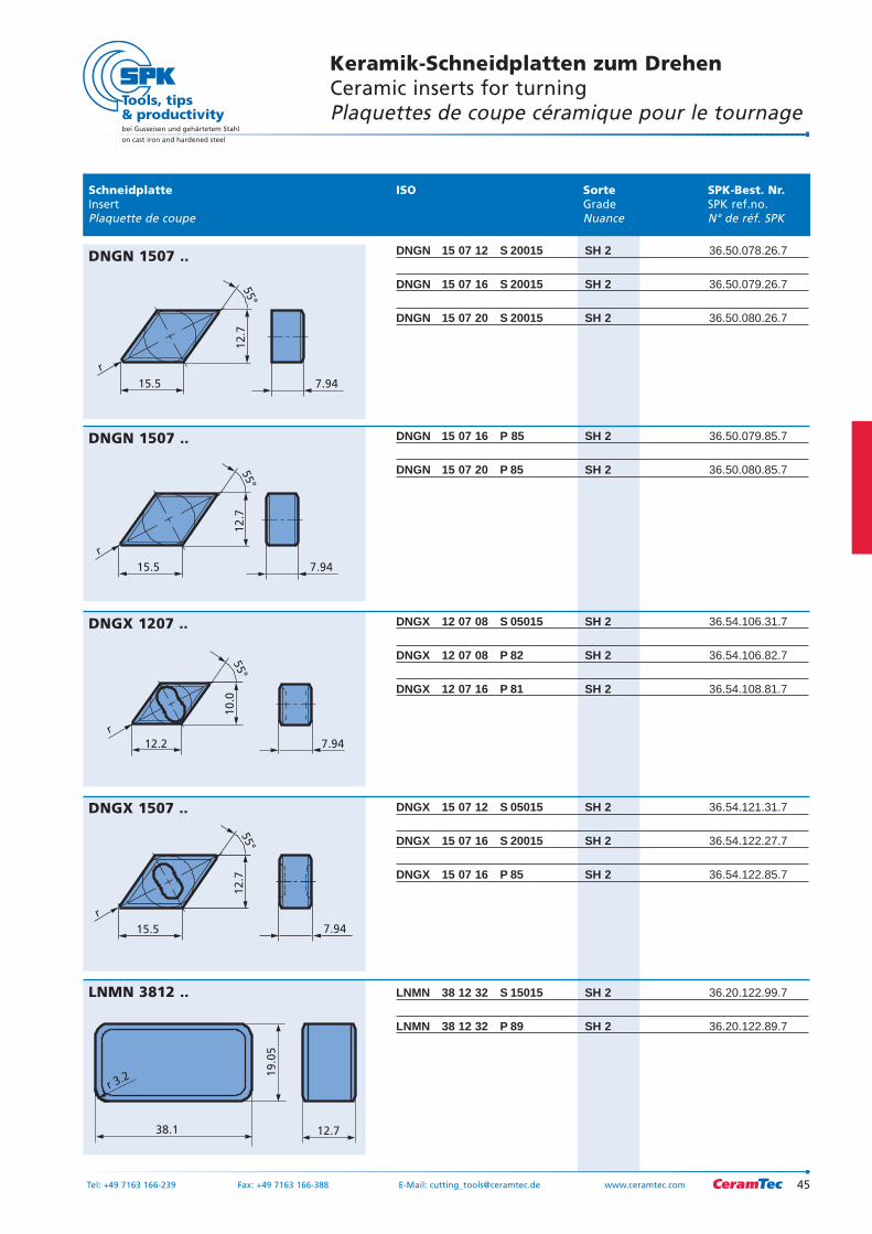
Keramik-Schneidplatten zum DrehenCeramic inserts for turningPlaquettes de coupe céramique pour le tournage
45Tel: +49 7163 166-239 Fax: +49 7163 166-388 E-Mail: [email protected] www.ceramtec.com
bei Gusseisen und gehärtetem Stahl
on cast iron and hardened steel
DNGN 15 07 12 S 20015 SH 2 36.50.078.26.7
DNGN 15 07 16 S 20015 SH 2 36.50.079.26.7
DNGN 15 07 20 S 20015 SH 2 36.50.080.26.7
DNGN 15 07 16 P 85 SH 2 36.50.079.85.7
DNGN 15 07 20 P 85 SH 2 36.50.080.85.7
DNGX 12 07 08 S 05015 SH 2 36.54.106.31.7
DNGX 12 07 08 P 82 SH 2 36.54.106.82.7
DNGX 12 07 16 P 81 SH 2 36.54.108.81.7
DNGX 15 07 12 S 05015 SH 2 36.54.121.31.7
DNGX 15 07 16 S 20015 SH 2 36.54.122.27.7
DNGX 15 07 16 P 85 SH 2 36.54.122.85.7
LNMN 38 12 32 S 15015 SH 2 36.20.122.99.7
LNMN 38 12 32 P 89 SH 2 36.20.122.89.7
55°
12.7
r
15.5 7.94
DNGN 1507 ..
55°
12.7
r
15.5 7.94
DNGN 1507 ..
55°
12.7
r
15.5 7.94
DNGX 1507 ..
r 3.2
12.7
19.0
5
38.1
LNMN 3812 ..
55°
10
.0
r
12.2 7.94
DNGX 1207 ..
Schneidplatte ISO Sorte SPK-Best. Nr.Insert Grade SPK ref.no.Plaquette de coupe Nuance N° de réf. SPK
bei Gusseisen und gehärtetem Stahl
on cast iron and hardened steel
46
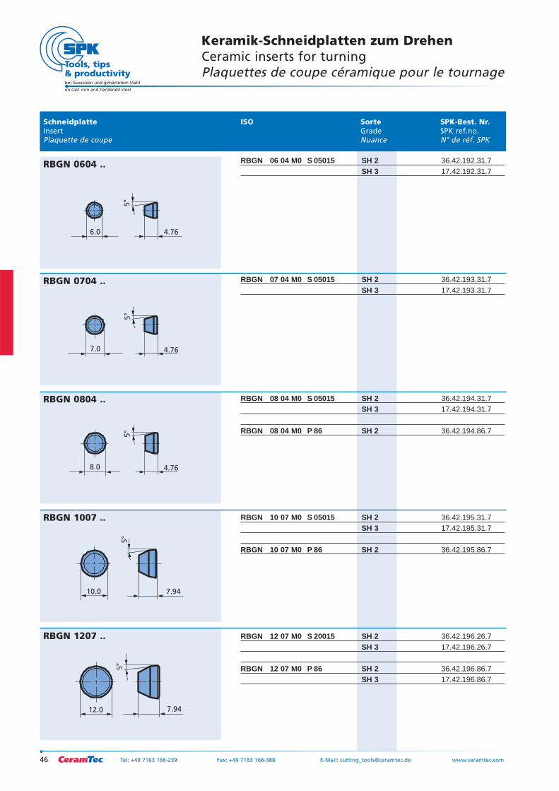
Keramik-Schneidplatten zum DrehenCeramic inserts for turningPlaquettes de coupe céramique pour le tournage
Tel: +49 7163 166-239 Fax: +49 7163 166-388 E-Mail: [email protected] www.ceramtec.com
RBGN 06 04 M0 S 05015 SH 2 36.42.192.31.7SH 3 17.42.192.31.7
RBGN 07 04 M0 S 05015 SH 2 36.42.193.31.7SH 3 17.42.193.31.7
RBGN 08 04 M0 S 05015 SH 2 36.42.194.31.7SH 3 17.42.194.31.7
RBGN 08 04 M0 P 86 SH 2 36.42.194.86.7
RBGN 10 07 M0 S 05015 SH 2 36.42.195.31.7SH 3 17.42.195.31.7
RBGN 10 07 M0 P 86 SH 2 36.42.195.86.7
RBGN 12 07 M0 S 20015 SH 2 36.42.196.26.7SH 3 17.42.196.26.7
RBGN 12 07 M0 P 86 SH 2 36.42.196.86.7SH 3 17.42.196.86.7
6.0
5°
4.76
RBGN 0604 ..
5°
7.0 4.76
RBGN 0704 ..
5°
8.0 4.76
RBGN 0804 ..
5°
10.0 7.94
RBGN 1007 ..
5°
7.9412.0
RBGN 1207 ..
Schneidplatte ISO Sorte SPK-Best. Nr.Insert Grade SPK ref.no.Plaquette de coupe Nuance N° de réf. SPK
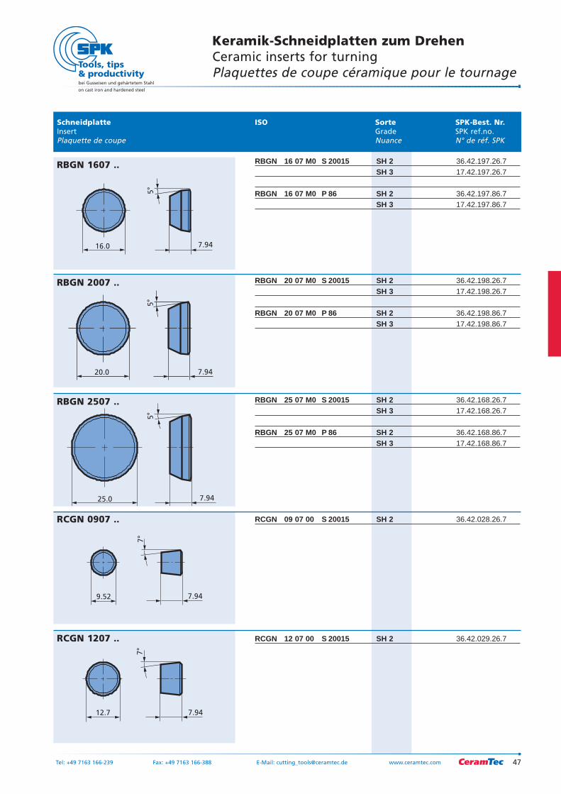
Keramik-Schneidplatten zum DrehenCeramic inserts for turningPlaquettes de coupe céramique pour le tournage
47Tel: +49 7163 166-239 Fax: +49 7163 166-388 E-Mail: [email protected] www.ceramtec.com
bei Gusseisen und gehärtetem Stahl
on cast iron and hardened steel
RBGN 16 07 M0 S 20015 SH 2 36.42.197.26.7SH 3 17.42.197.26.7
RBGN 16 07 M0 P 86 SH 2 36.42.197.86.7SH 3 17.42.197.86.7
RBGN 20 07 M0 S 20015 SH 2 36.42.198.26.7SH 3 17.42.198.26.7
RBGN 20 07 M0 P 86 SH 2 36.42.198.86.7SH 3 17.42.198.86.7
RBGN 25 07 M0 S 20015 SH 2 36.42.168.26.7SH 3 17.42.168.26.7
RBGN 25 07 M0 P 86 SH 2 36.42.168.86.7SH 3 17.42.168.86.7
RCGN 09 07 00 S 20015 SH 2 36.42.028.26.7
RCGN 12 07 00 S 20015 SH 2 36.42.029.26.7
5°
7.9416.0
RBGN 1607 ..
5°
7.9420.0
RBGN 2007 ..
5°
7.9425.0
RBGN 2507 ..
7°
7.949.52
RCGN 0907 ..
7°
7.9412.7
RCGN 1207 ..
Schneidplatte ISO Sorte SPK-Best. Nr.Insert Grade SPK ref.no.Plaquette de coupe Nuance N° de réf. SPK
bei Gusseisen und gehärtetem Stahl
on cast iron and hardened steel
48
Keramik-Schneidplatten zum DrehenCeramic inserts for turningPlaquettes de coupe céramique pour le tournage
Tel: +49 7163 166-239 Fax: +49 7163 166-388 E-Mail: [email protected] www.ceramtec.com
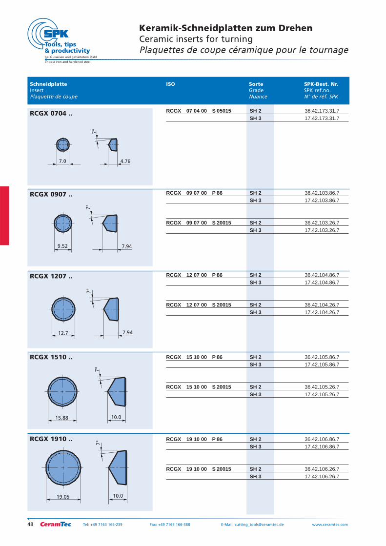
RCGX 07 04 00 S 05015 SH 2 36.42.173.31.7SH 3 17.42.173.31.7
RCGX 09 07 00 P 86 SH 2 36.42.103.86.7SH 3 17.42.103.86.7
RCGX 09 07 00 S 20015 SH 2 36.42.103.26.7SH 3 17.42.103.26.7
RCGX 12 07 00 P 86 SH 2 36.42.104.86.7SH 3 17.42.104.86.7
RCGX 12 07 00 S 20015 SH 2 36.42.104.26.7SH 3 17.42.104.26.7
RCGX 15 10 00 P 86 SH 2 36.42.105.86.7SH 3 17.42.105.86.7
RCGX 15 10 00 S 20015 SH 2 36.42.105.26.7SH 3 17.42.105.26.7
RCGX 19 10 00 P 86 SH 2 36.42.106.86.7SH 3 17.42.106.86.7
RCGX 19 10 00 S 20015 SH 2 36.42.106.26.7SH 3 17.42.106.26.7
7.0 4.76
7°
RCGX 0704 ..
7°
7.949.52
RCGX 0907 ..
7°
7.9412.7
RCGX 1207 ..
7°
10.015.88
RCGX 1510 ..
7°
10.019.05
RCGX 1910 ..
Schneidplatte ISO Sorte SPK-Best. Nr.Insert Grade SPK ref.no.Plaquette de coupe Nuance N° de réf. SPK
Keramik-Schneidplatten zum DrehenCeramic inserts for turningPlaquettes de coupe céramique pour le tournage
49Tel: +49 7163 166-239 Fax: +49 7163 166-388 E-Mail: [email protected] www.ceramtec.com
bei Gusseisen und gehärtetem Stahl
on cast iron and hardened steel
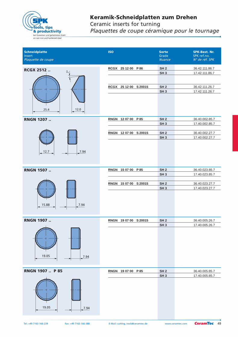
RCGX 25 12 00 P 86 SH 2 36.42.111.86.7SH 3 17.42.111.86.7
RCGX 25 12 00 S 20015 SH 2 36.42.111.26.7SH 3 17.42.111.26.7
RNGN 12 07 00 P 85 SH 2 36.40.002.85.7SH 3 17.40.002.85.7
RNGN 12 07 00 S 20015 SH 2 36.40.002.27.7SH 3 17.40.002.27.7
RNGN 15 07 00 P 85 SH 2 36.40.023.85.7SH 3 17.40.023.85.7
RNGN 15 07 00 S 20015 SH 2 36.40.023.27.7 SH 3 17.40.023.27.7
RNGN 19 07 00 S 20015 SH 2 36.40.005.26.7SH 3 17.40.005.26.7
RNGN 19 07 00 P 85 SH 2 36.40.005.85.7SH 3 17.40.005.85.7
7°
12.025.4
RCGX 2512 ..
12.7 7.94
RNGN 1207 ..
15.88 7.94
RNGN 1507 ..
7.9419.05
RNGN 1907 ..
7.9419.05
RNGN 1907 .. P 85
Schneidplatte ISO Sorte SPK-Best. Nr.Insert Grade SPK ref.no.Plaquette de coupe Nuance N° de réf. SPK
bei Gusseisen und gehärtetem Stahl
on cast iron and hardened steel
50
Keramik-Schneidplatten zum DrehenCeramic inserts for turningPlaquettes de coupe céramique pour le tournage
Tel: +49 7163 166-239 Fax: +49 7163 166-388 E-Mail: [email protected] www.ceramtec.com
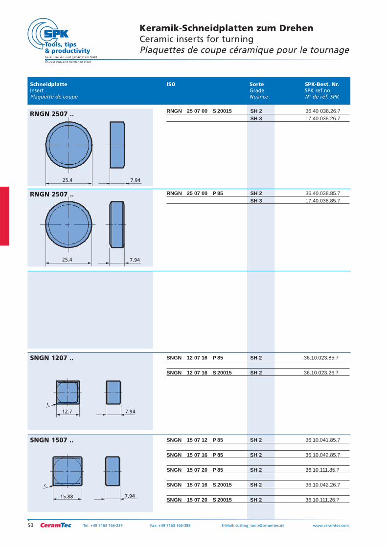
RNGN 25 07 00 S 20015 SH 2 36.40 038.26.7SH 3 17.40.038.26.7
RNGN 25 07 00 P 85 SH 2 36.40.038.85.7SH 3 17.40.038.85.7
SNGN 12 07 16 P 85 SH 2 36.10.023.85.7
SNGN 12 07 16 S 20015 SH 2 36.10.023.26.7
SNGN 15 07 12 P 85 SH 2 36.10.041.85.7
SNGN 15 07 16 P 85 SH 2 36.10.042.85.7
SNGN 15 07 20 P 85 SH 2 36.10.111.85.7
SNGN 15 07 16 S 20015 SH 2 36.10.042.26.7
SNGN 15 07 20 S 20015 SH 2 36.10.111.26.7
7.9425.4
RNGN 2507 ..
7.9425.4
RNGN 2507 ..
7.94
r
12.7
SNGN 1207 ..
15.88
r
7.94
SNGN 1507 ..
Schneidplatte ISO Sorte SPK-Best. Nr.Insert Grade SPK ref.no.Plaquette de coupe Nuance N° de réf. SPK
Keramik-Schneidplatten zum DrehenCeramic inserts for turningPlaquettes de coupe céramique pour le tournage
51Tel: +49 7163 166-239 Fax: +49 7163 166-388 E-Mail: [email protected] www.ceramtec.com
bei Gusseisen und gehärtetem Stahl
on cast iron and hardened steel
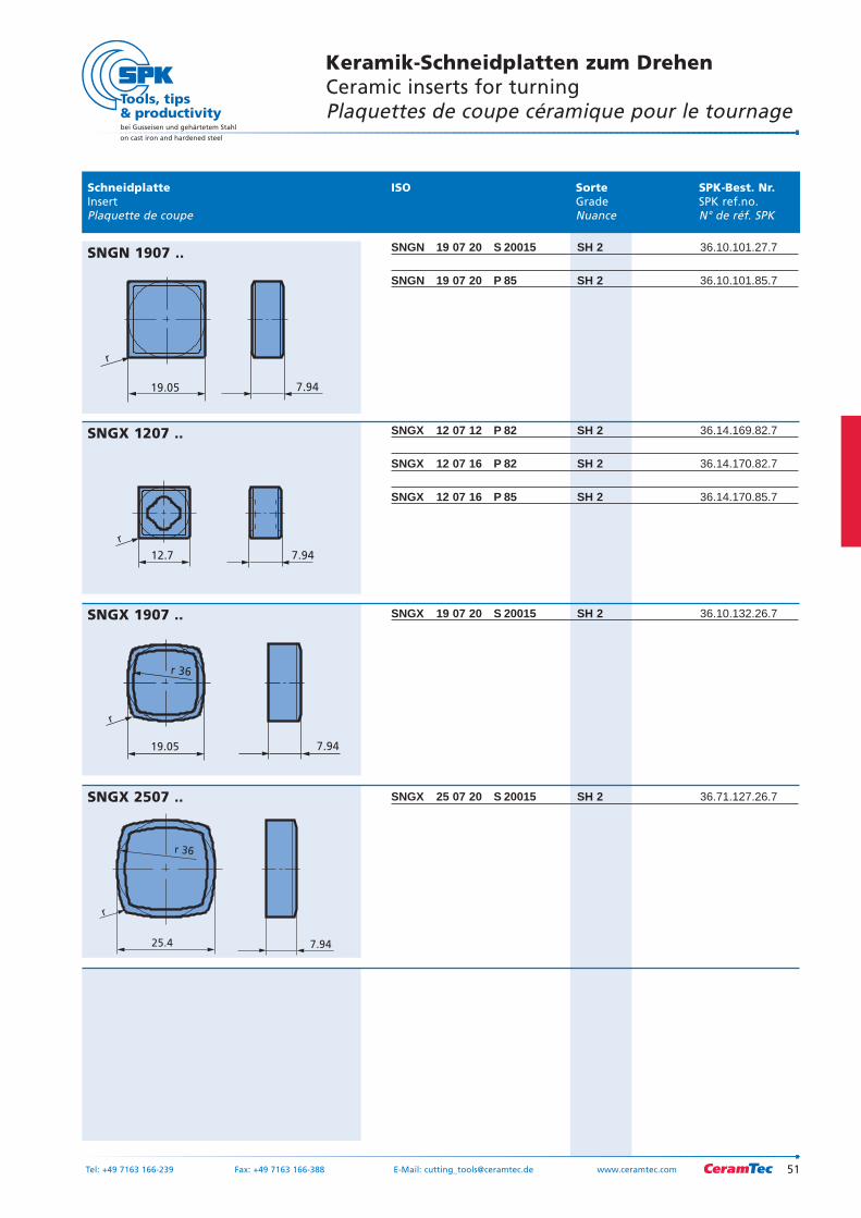
SNGN 19 07 20 S 20015 SH 2 36.10.101.27.7
SNGN 19 07 20 P 85 SH 2 36.10.101.85.7
SNGX 12 07 12 P 82 SH 2 36.14.169.82.7
SNGX 12 07 16 P 82 SH 2 36.14.170.82.7
SNGX 12 07 16 P 85 SH 2 36.14.170.85.7
SNGX 19 07 20 S 20015 SH 2 36.10.132.26.7
SNGX 25 07 20 S 20015 SH 2 36.71.127.26.7
r
7.9419.05
SNGN 1907 ..
7.94
r
12.7
SNGX 1207 ..
25.4 7.94
r
r 36
SNGX 2507 ..
19.05 7.94
r
r 36
SNGX 1907 ..
Schneidplatte ISO Sorte SPK-Best. Nr.Insert Grade SPK ref.no.Plaquette de coupe Nuance N° de réf. SPK
bei Gusseisen und gehärtetem Stahl
on cast iron and hardened steel
52
Keramik-Schneidplatten zum DrehenCeramic inserts for turningPlaquettes de coupe céramique pour le tournage
Tel: +49 7163 166-239 Fax: +49 7163 166-388 E-Mail: [email protected] www.ceramtec.com
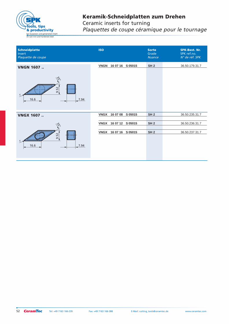
VNGN 16 07 16 S 05015 SH 2 36.50.179.31.7
VNGX 16 07 08 S 05015 SH 2 36.50.235.31.7
VNGX 16 07 12 S 05015 SH 2 36.50.236.31.7
VNGX 16 07 16 S 05015 SH 2 36.50.237.31.7
16.6
r
7.94
35°
9.5
2
VNGN 1607 ..
16.6
r
7.94
35°
9.5
2
VNGX 1607 ..
53Tel: +49 7163 166-239 Fax: +49 7163 166-388 E-Mail: [email protected] www.ceramtec.com
bei Gusseisen und gehärtetem Stahl
on cast iron and hardened steel
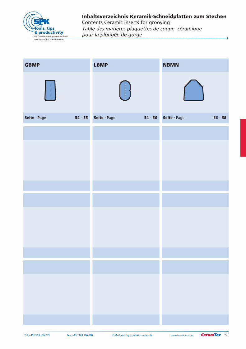
GBMP
Seite Page 54 - 55
LBMP
Seite Page 54 - 56
NBMN
Seite Page 56 - 58
Inhaltsverzeichnis Keramik-Schneidplatten zum StechenContents Ceramic inserts for groovingTable des matières plaquettes de coupe céramiquepour la plongée de gorge
bei Gusseisen und gehärtetem Stahl
on cast iron and hardened steel
54 Tel: +49 7163 166-239 Fax: +49 7163 166-388 E-Mail: [email protected] www.ceramtec.com
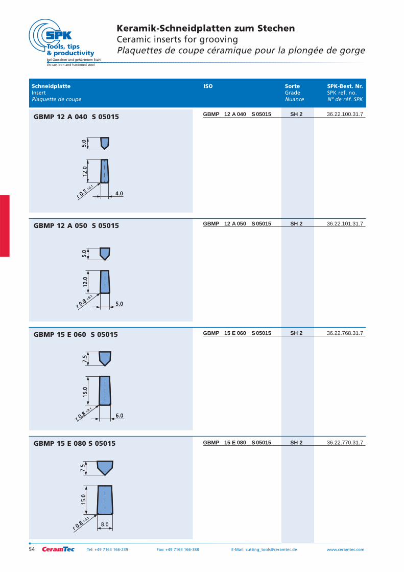
GBMP 12 A 040 S 05015 SH 2 36.22.100.31.7
GBMP 12 A 050 S 05015 SH 2 36.22.101.31.7
GBMP 15 E 060 S 05015 SH 2 36.22.768.31.7
GBMP 15 E 080 S 05015 SH 2 36.22.770.31.7
15
.07.5
r 0.80.1
8.0
15
.07.5
r 0.80.1
GBMP 15 E 080 S 05015
6.0
15.0
7.5
r 0.80.1
6.0
15.0
7.5
r 0.80.1
GBMP 15 E 060 S 05015
5.0
12.0
5.0
r 0.80.1
5.0
12.0
5.0
r 0.80.1
GBMP 12 A 050 S 05015
4.0
12.0
5.0
r 0.50.1
4.0
12.0
5.0
r 0.50.1
GBMP 12 A 040 S 05015
Schneidplatte ISO Sorte SPK-Best. Nr.Insert Grade SPK ref. no.Plaquette de coupe Nuance N° de réf. SPK
Keramik-Schneidplatten zum StechenCeramic inserts for groovingPlaquettes de coupe céramique pour la plongée de gorge
55Tel: +49 7163 166-239 Fax: +49 7163 166-388 E-Mail: [email protected] www.ceramtec.com
bei Gusseisen und gehärtetem Stahl
on cast iron and hardened steel
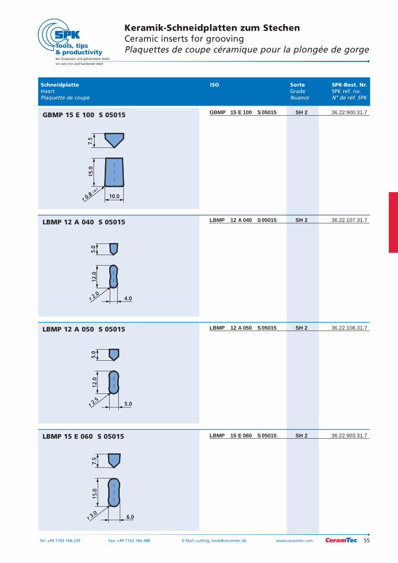
GBMP 15 E 100 S 05015 SH 2 36.22.900.31.7
LBMP 12 A 040 S 05015 SH 2 36.22.107.31.7
LBMP 12 A 050 S 05015 SH 2 36.22.108.31.7
LBMP 15 E 060 S 05015 SH 2 36.22.903.31.7
6.0
15.0
7.5
r 3.06.0
15.0
7.5
r 3.0
LBMP 15 E 060 S 05015
5.0
12
.05
.0
r 2.55.0
12
.05
.0
r 2.5
LBMP 12 A 050 S 05015
4.0
12
.05
.0
r 2.04.0
12
.05
.0
r 2.0
LBMP 12 A 040 S 05015
10.0
15.0
7.5
r 0.80.1
10.0
15.0
7.5
r 0.80.1
GBMP 15 E 100 S 05015
Schneidplatte ISO Sorte SPK-Best. Nr.Insert Grade SPK ref. no.Plaquette de coupe Nuance N° de réf. SPK
Keramik-Schneidplatten zum StechenCeramic inserts for groovingPlaquettes de coupe céramique pour la plongée de gorge
bei Gusseisen und gehärtetem Stahl
on cast iron and hardened steel
56 Tel: +49 7163 166-239 Fax: +49 7163 166-388 E-Mail: [email protected] www.ceramtec.com
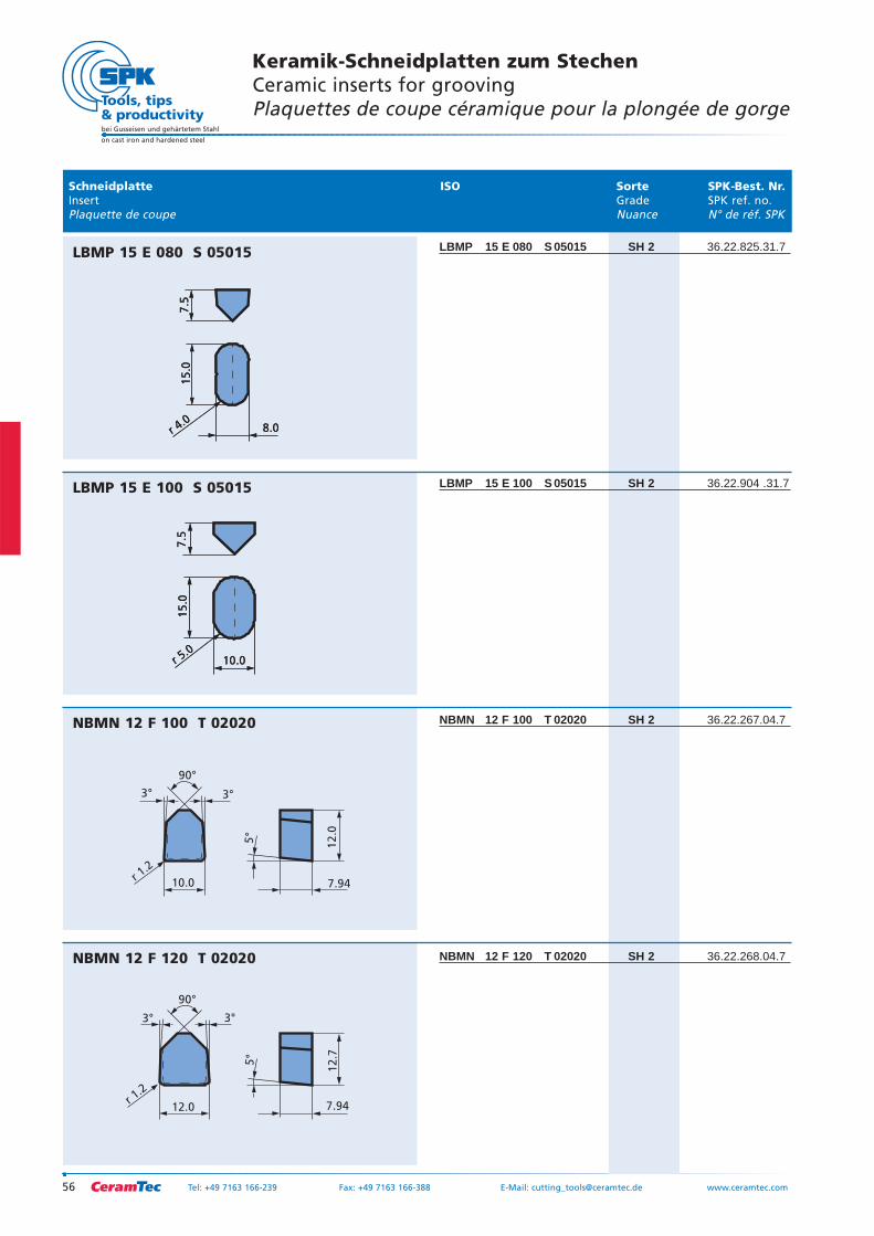
LBMP 15 E 080 S 05015 SH 2 36.22.825.31.7
LBMP 15 E 100 S 05015 SH 2 36.22.904 .31.7
NBMN 12 F 100 T 02020 SH 2 36.22.267.04.7
NBMN 12 F 120 T 02020 SH 2 36.22.268.04.7
r 1.2
7.94
12.7
5°
12.0
3° 3°
90°
NBMN 12 F 120 T 02020
r 1.2
7.94
12.0
5°
10.0
3° 3°
90°
NBMN 12 F 100 T 02020
10.0
15.0
7.5
r 5.010.0
15.0
7.5
r 5.0
LBMP 15 E 100 S 05015
8.0
15.0
7.5
r 4.08.0
15.0
7.5
r 4.0
LBMP 15 E 080 S 05015
Schneidplatte ISO Sorte SPK-Best. Nr.Insert Grade SPK ref. no.Plaquette de coupe Nuance N° de réf. SPK
Keramik-Schneidplatten zum StechenCeramic inserts for groovingPlaquettes de coupe céramique pour la plongée de gorge
57Tel: +49 7163 166-239 Fax: +49 7163 166-388 E-Mail: [email protected] www.ceramtec.com
bei Gusseisen und gehärtetem Stahl
on cast iron and hardened steel
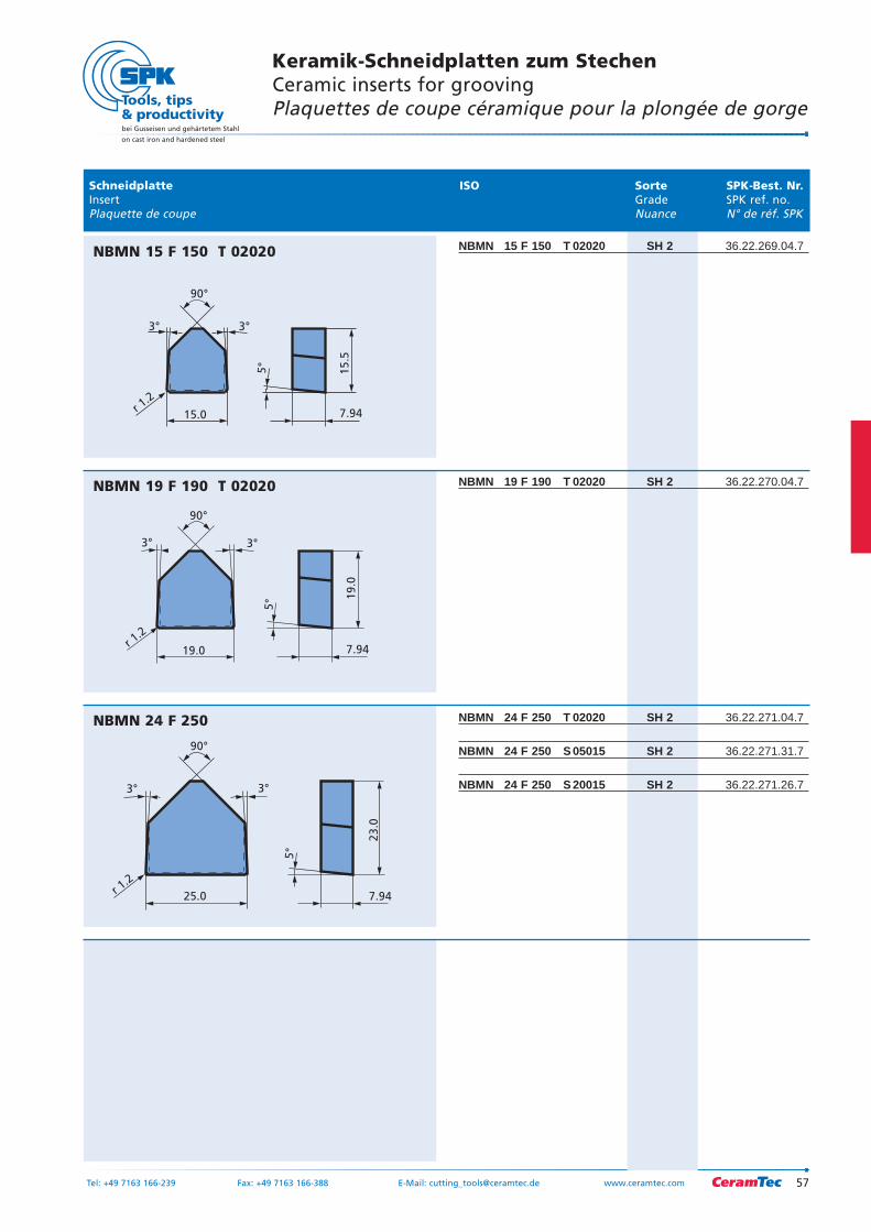
NBMN 15 F 150 T 02020 SH 2 36.22.269.04.7
NBMN 19 F 190 T 02020 SH 2 36.22.270.04.7
NBMN 24 F 250 T 02020 SH 2 36.22.271.04.7
NBMN 24 F 250 S 05015 SH 2 36.22.271.31.7
NBMN 24 F 250 S 20015 SH 2 36.22.271.26.7
r 1.2
7.94
23
.0
5°
25.0
3° 3°
90°
NBMN 24 F 250
r 1.2
7.94
19.0
5°
19.0
3° 3°
90°
NBMN 19 F 190 T 02020
r 1.2
7.94
15
.5
5°
15.0
3° 3°
90°
NBMN 15 F 150 T 02020
Schneidplatte ISO Sorte SPK-Best. Nr.Insert Grade SPK ref. no.Plaquette de coupe Nuance N° de réf. SPK
Keramik-Schneidplatten zum StechenCeramic inserts for groovingPlaquettes de coupe céramique pour la plongée de gorge
bei Gusseisen und gehärtetem Stahl
on cast iron and hardened steel
58 Tel: +49 7163 166-239 Fax: +49 7163 166-388 E-Mail: [email protected] www.ceramtec.com
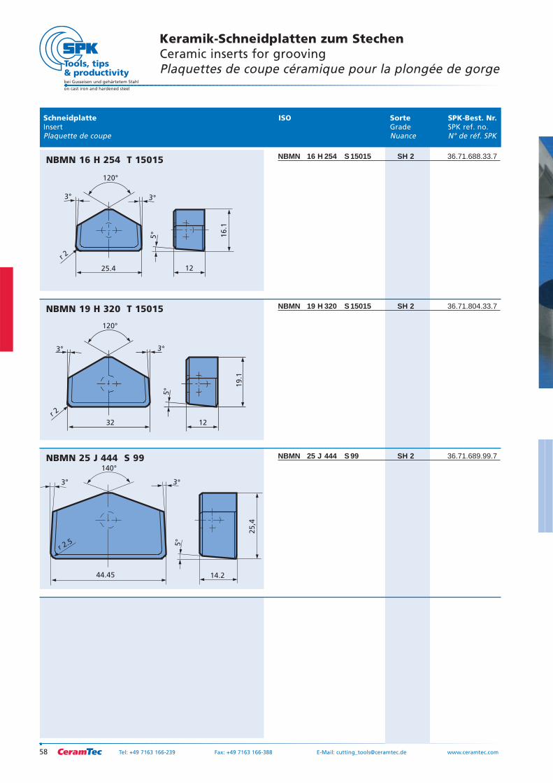
NBMN 16 H 254 S 15015 SH 2 36.71.688.33.7
NBMN 19 H 320 S 15015 SH 2 36.71.804.33.7
NBMN 25 J 444 S 99 SH 2 36.71.689.99.7
14.2
25
,4
5°
44.45
3° 3°
140°
r 2.5
NBMN 25 J 444 S 99
r 2
12
19
.1
5°
32
3° 3°
120°
NBMN 19 H 320 T 15015
r 2
12
16.1
5°
25.4
3° 3°
120°
NBMN 16 H 254 T 15015
Schneidplatte ISO Sorte SPK-Best. Nr.Insert Grade SPK ref. no.Plaquette de coupe Nuance N° de réf. SPK
Keramik-Schneidplatten zum StechenCeramic inserts for groovingPlaquettes de coupe céramique pour la plongée de gorge
59Tel: +49 7163 166-239 Fax: +49 7163 166-388 E-Mail: [email protected] www.ceramtec.com
bei Gusseisen und gehärtetem Stahl
on cast iron and hardened steel
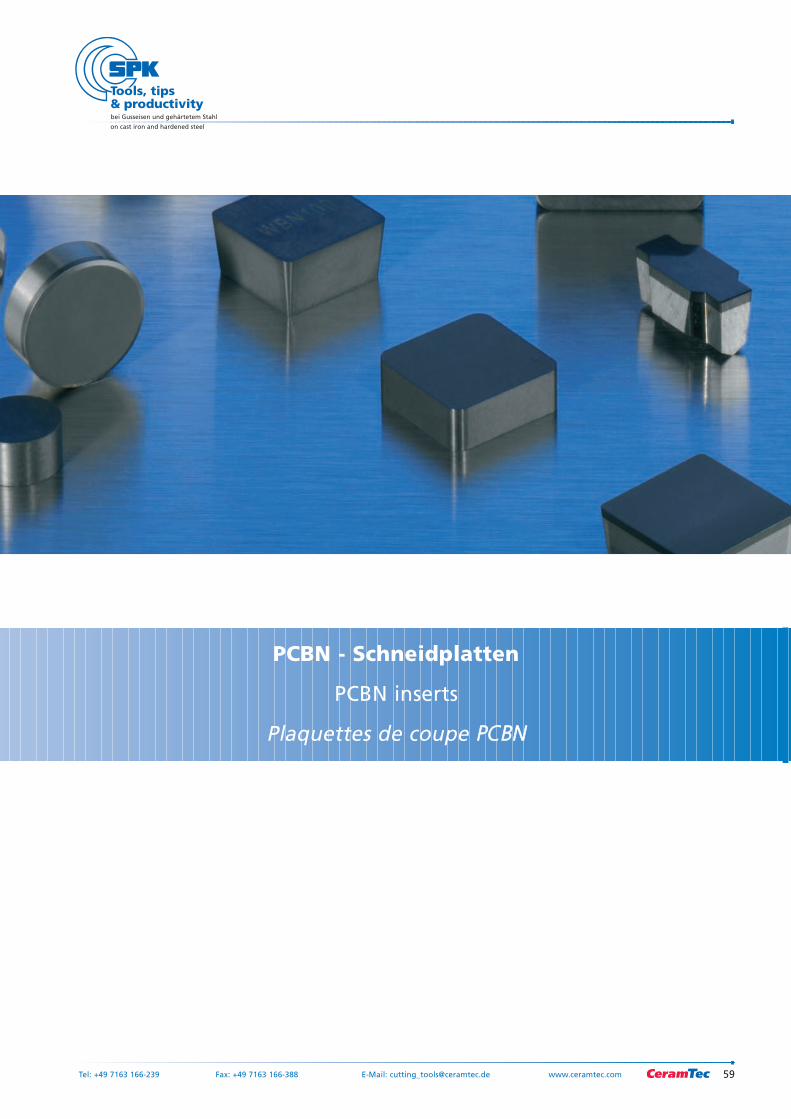
PCBN - Schneidplatten
PCBN inserts
Plaquettes de coupe PCBN
bei Gusseisen und gehärtetem Stahl
on cast iron and hardened steel
60 Tel: +49 7163 166-239 Fax: +49 7163 166-388 E-Mail: [email protected] www.ceramtec.com
61Tel: +49 7163 166-239 Fax: +49 7163 166-388 E-Mail: [email protected] www.ceramtec.com
bei Gusseisen und gehärtetem Stahl
on cast iron and hardened steel
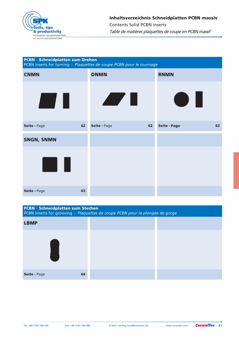
Inhaltsverzeichnis Schneidplatten PCBN massiv
Contents Solid PCBN inserts
Table de matières plaquettes de coupe en PCBN massif
CNMN
Seite Page 62
DNMN
Seite Page 62
RNMN
Seite Page 62
SNGN, SNMN
Seite Page 63
Seite Page 64
PCBN - Schneidplatten zum StechenPCBN inserts for grooving Plaquettes de coupe PCBN pour la plongée de gorge
PCBN - Schneidplatten zum DrehenPCBN inserts for turning Plaquettes de coupe PCBN pour le tournage
LBMP
Schneidplatte ISO Sorte SPK-Best. Nr.Insert Grade SPK ref.no.Plaquette de coupe Nuance N° de réf. SPK
bei Gusseisen und gehärtetem Stahl
on cast iron and hardened steel
62 Tel: +49 7163 166-239 Fax: +49 7163 166-388 E-Mail: [email protected] www.ceramtec.com
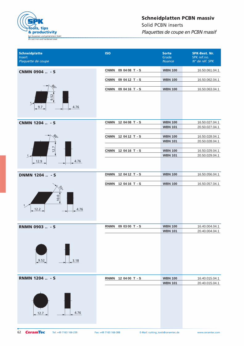
Schneidplatten PCBN massivSolid PCBN insertsPlaquettes de coupe en PCBN massif
CNMN 09 04 08 T - S WBN 100 16.50.061.04.1
CNMN 09 04 12 T - S WBN 100 16.50.062.04.1
CNMN 09 04 16 T - S WBN 100 16.50.063.04.1
CNMN 12 04 08 T - S WBN 100 16.50.027.04.1WBN 101 20.50.027.04.1
CNMN 12 04 12 T - S WBN 100 16.50.028.04.1WBN 101 20.50.028.04.1
CNMN 12 04 16 T - S WBN 100 16.50.029.04.1WBN 101 20.50.029.04.1
DNMN 12 04 12 T - S WBN 100 16.50.056.04.1
DNMN 12 04 16 T - S WBN 100 16.50.057.04.1
RNMN 09 03 00 T - S WBN 100 16.40.004.04.1WBN 101 20.40.004.04.1
RNMN 12 04 00 T - S WBN 100 16.40.015.04.1WBN 101 20.40.015.04.1
12.9
80°
12
.7
r
4.76
CNMN 1204 .. - S
4.76
55°
10
.0
r
12.2
DNMN 1204 .. - S
9.52 3.18
RNMN 0903 .. - S
12.7 4.76
RNMN 1204 .. - S
9.7
80°
9.5
2
r
4.76
CNMN 0904 .. - S
Schneidplatte ISO Sorte SPK-Best. Nr.Insert Grade SPK ref.no.Plaquette de coupe Nuance N° de réf. SPK
63Tel: +49 7163 166-239 Fax: +49 7163 166-388 E-Mail: [email protected] www.ceramtec.com
bei Gusseisen und gehärtetem Stahl
on cast iron and hardened steel
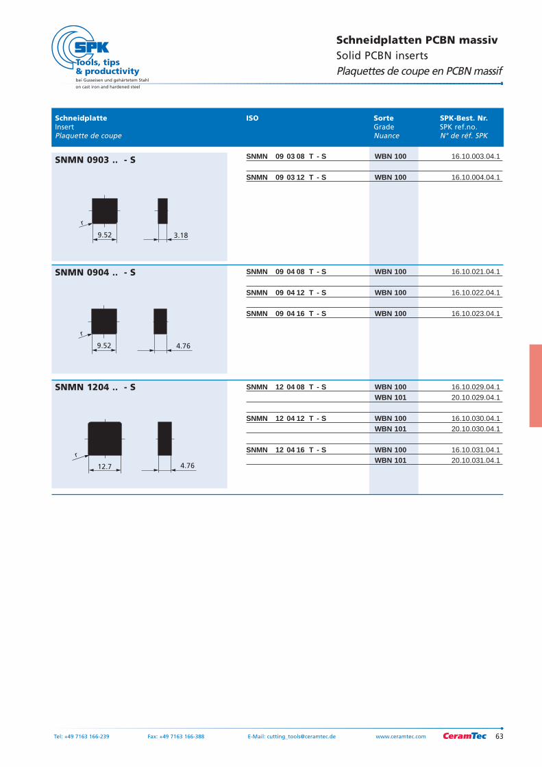
Schneidplatten PCBN massivSolid PCBN insertsPlaquettes de coupe en PCBN massif
SNMN 09 03 08 T - S WBN 100 16.10.003.04.1
SNMN 09 03 12 T - S WBN 100 16.10.004.04.1
SNMN 09 04 08 T - S WBN 100 16.10.021.04.1
SNMN 09 04 12 T - S WBN 100 16.10.022.04.1
SNMN 09 04 16 T - S WBN 100 16.10.023.04.1
SNMN 12 04 08 T - S WBN 100 16.10.029.04.1WBN 101 20.10.029.04.1
SNMN 12 04 12 T - S WBN 100 16.10.030.04.1WBN 101 20.10.030.04.1
SNMN 12 04 16 T - S WBN 100 16.10.031.04.1WBN 101 20.10.031.04.1
9.52
r
3.18
SNMN 0903 .. - S
4.769.52
r
SNMN 0904 .. - S
12.7
r
4.76
SNMN 1204 .. - S
4.0
12.0
5.0
r 2.04.0
12.0
5.0
r 2.0
Schneidplatte ISO Sorte SPK-Best. Nr.Insert Grade SPK ref.no.Plaquette de coupe Nuance N° de réf. SPK
bei Gusseisen und gehärtetem Stahl
on cast iron and hardened steel
64 Tel: +49 7163 166-239 Fax: +49 7163 166-388 E-Mail: [email protected] www.ceramtec.com
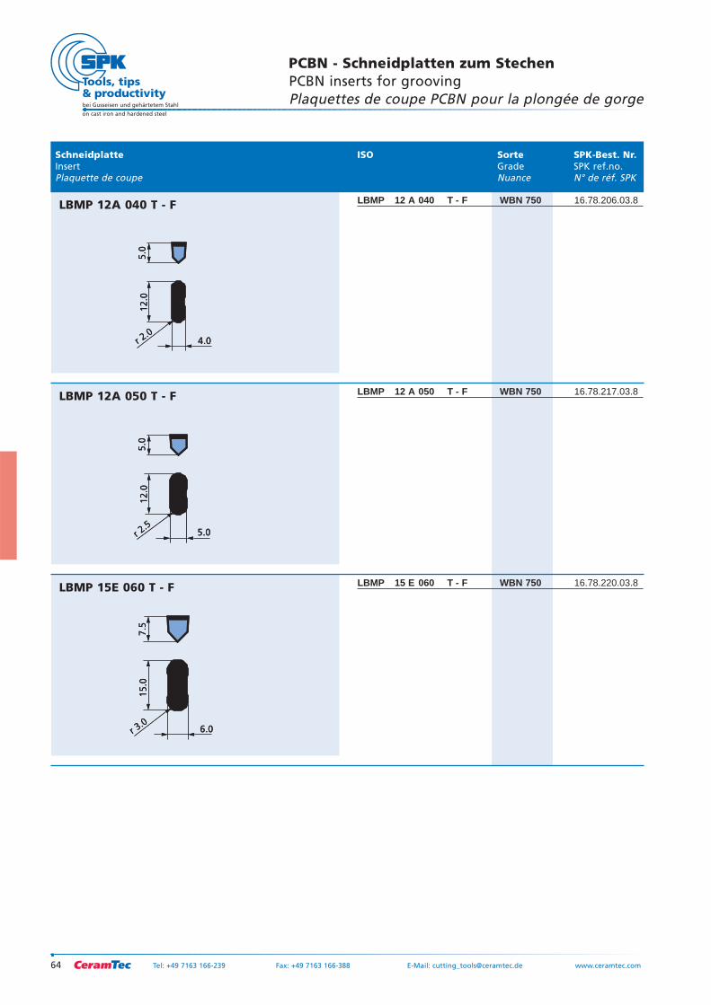
PCBN - Schneidplatten zum StechenPCBN inserts for groovingPlaquettes de coupe PCBN pour la plongée de gorge
LBMP 12 A 050 T - F WBN 750 16.78.217.03.8
LBMP 12 A 040 T - F WBN 750 16.78.206.03.8
LBMP 15 E 060 T - F WBN 750 16.78.220.03.8
6.0
15.0
7.5
r 3.06.0
15.0
7.5
r 3.0
LBMP 15E 060 T - F
5.0
12
.05
.0
r 2.55.0
12
.05
.0
r 2.5
LBMP 12A 050 T - F
LBMP 12A 040 T - F
65
bei Gusseisen und gehärtetem Stahl
on cast iron and hardened steel
Tel: +49 7163 166-239 Fax: +49 7163 166-388 E-Mail: [email protected] www.ceramtec.com
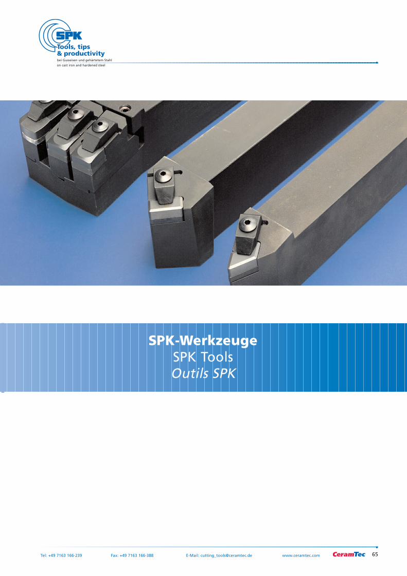
SPK-WerkzeugeSPK ToolsOutils SPK
66
bei Gusseisen und gehärtetem Stahl
on cast iron and hardened steel
Tel: +49 7163 166-239 Fax: +49 7163 166-388 E-Mail: [email protected] www.ceramtec.com
67
bei Gusseisen und gehärtetem Stahl
on cast iron and hardened steel
Tel: +49 7163 166-239 Fax: +49 7163 166-388 E-Mail: [email protected] www.ceramtec.com
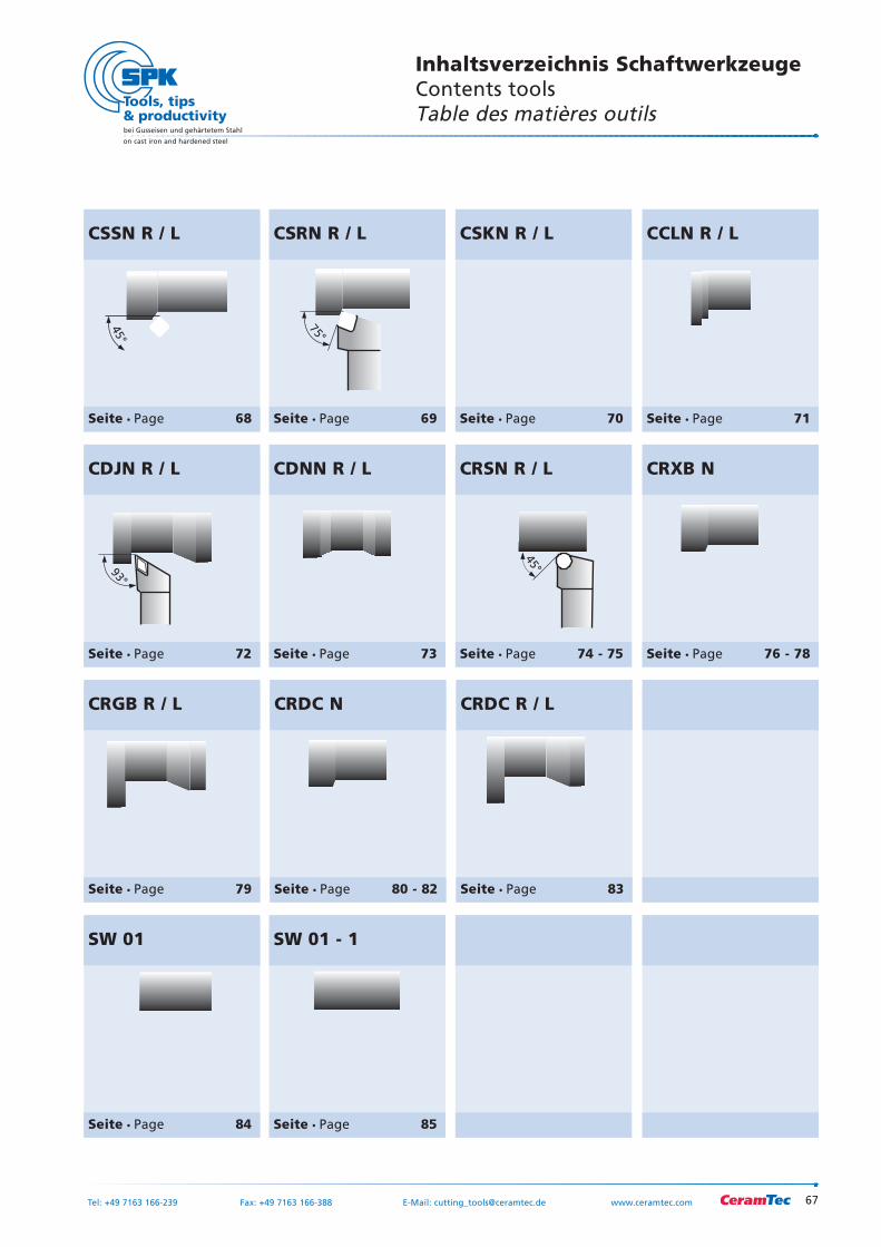
Inhaltsverzeichnis SchaftwerkzeugeContents toolsTable des matières outils
SW 01 - 1
Seite Page 85
SW 01
Seite Page 84
63°
CDNN R / L
Seite Page 73
CRGB R / L
Seite Page 79
93°
CDJN R / L
Seite Page 72
CRXB N
Seite Page 76 - 78
CRDC R / L
Seite Page 83
45°
CRSN R / L
Seite Page 74 - 75
CRDC N
Seite Page 80 - 82
75°
CSKN R / L
Seite Page 70
75°
CSRN R / L
Seite Page 69
45°
CSSN R / L
Seite Page 68
95°
CCLN R / L
Seite Page 71
68
bei Gusseisen und gehärtetem Stahl
on cast iron and hardened steel
Tel: +49 7163 166-239 Fax: +49 7163 166-388 E-Mail: [email protected] www. ceramtec.com
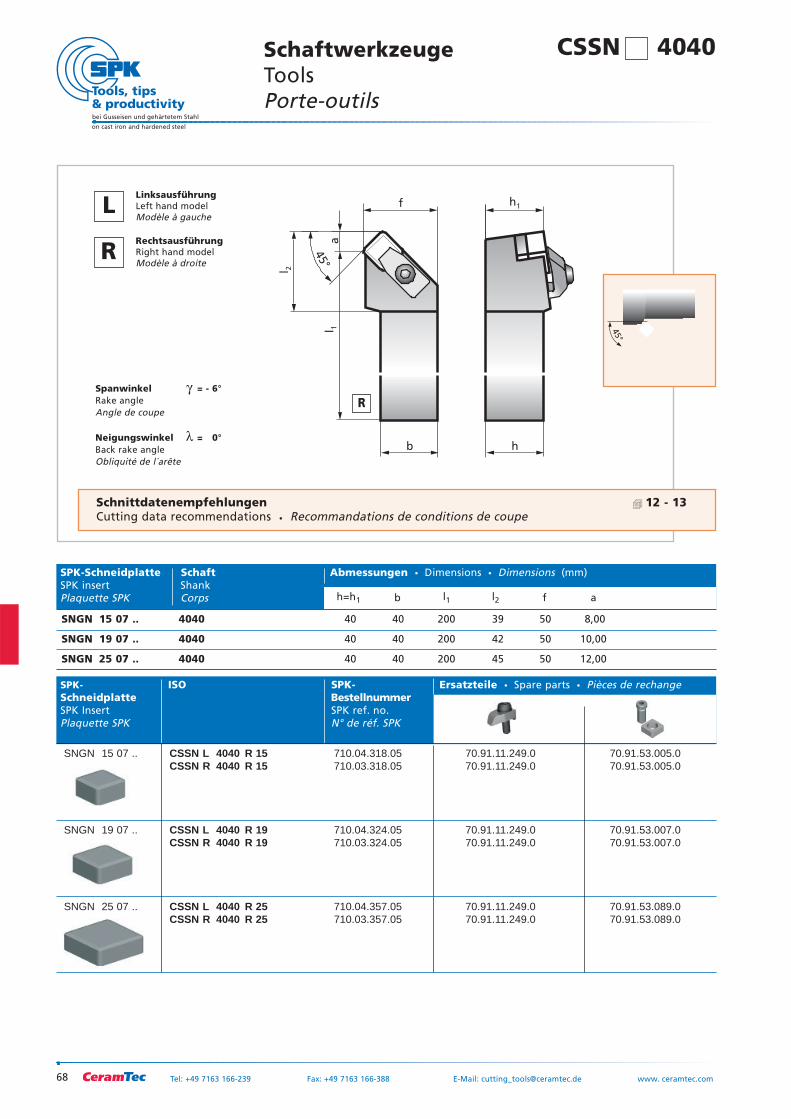
b
f
h
l 2
l 1
h1
45°
a
Spanwinkel γ = - 6°Rake angleAngle de coupe
Neigungswinkel λ = 0°Back rake angleObliquité de l´arête
SPK- ISO SPK- Ersatzteile Spare parts Pièces de rechangeSchneidplatte BestellnummerSPK Insert SPK ref. no.Plaquette SPK N° de réf. SPK
SNGN 15 07 .. CSSN L 4040 R 15 710.04.318.05 70.91.11.249.0 70.91.53.005.0CSSN R 4040 R 15 710.03.318.05 70.91.11.249.0 70.91.53.005.0
SNGN 19 07 .. CSSN L 4040 R 19 710.04.324.05 70.91.11.249.0 70.91.53.007.0CSSN R 4040 R 19 710.03.324.05 70.91.11.249.0 70.91.53.007.0
SNGN 25 07 .. CSSN L 4040 R 25 710.04.357.05 70.91.11.249.0 70.91.53.089.0CSSN R 4040 R 25 710.03.357.05 70.91.11.249.0 70.91.53.089.0
45°
SPK-Schneidplatte Schaft Abmessungen Dimensions Dimensions (mm)SPK insert ShankPlaquette SPK Corps h=h1 b l1 l2 f a
SNGN 15 07 .. 4040 40 40 200 39 50 8,00
SNGN 19 07 .. 4040 40 40 200 42 50 10,00
SNGN 25 07 .. 4040 40 40 200 45 50 12,00
SchaftwerkzeugeTools Porte-outils
R
LLinksausführungLeft hand modelModèle à gauche
RRechtsausführungRight hand modelModèle à droite
CSSN 4040
Schnittdatenempfehlungen 12 - 13Cutting data recommendations Recommandations de conditions de coupe
69
bei Gusseisen und gehärtetem Stahl
on cast iron and hardened steel
Tel: +49 7163 166-239 Fax: +49 7163 166-388 E-Mail: [email protected] www.ceramtec.com
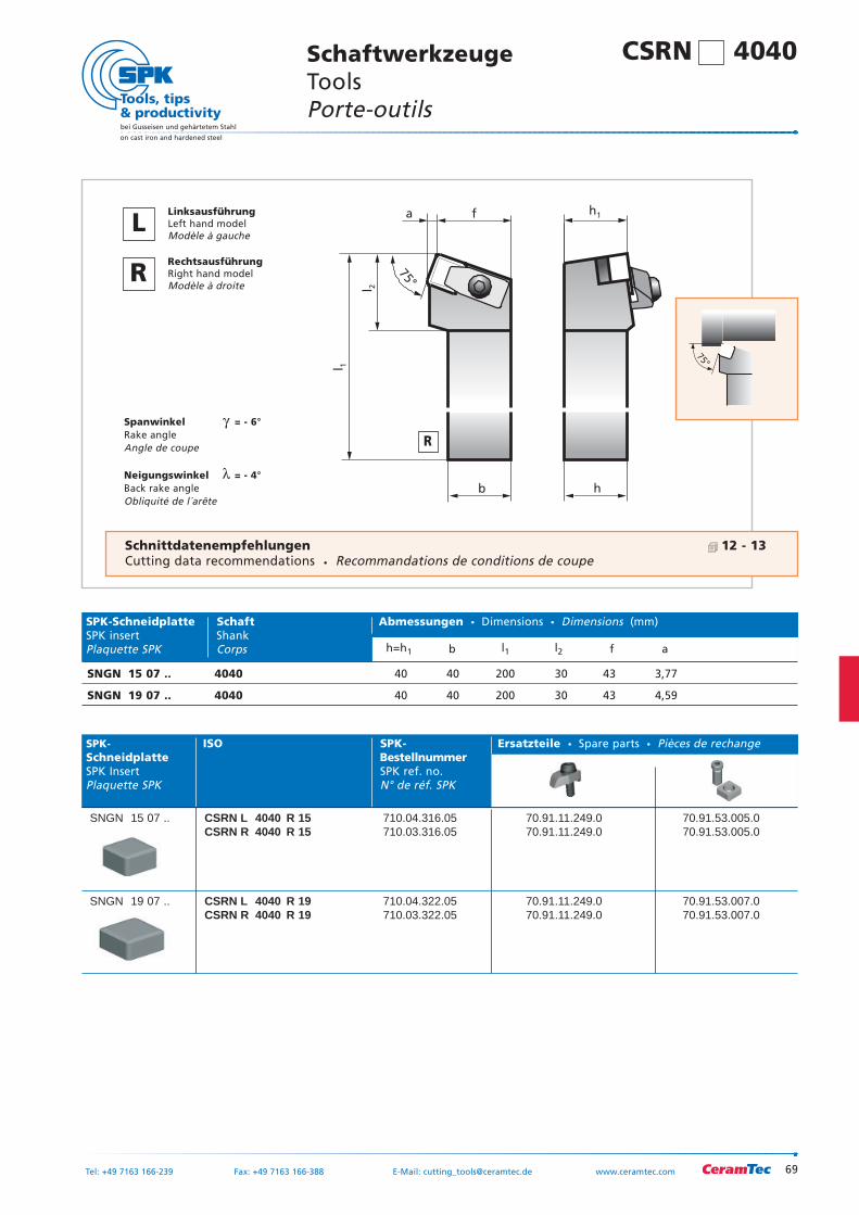
b
a f
h
l 2
l 1
h1
75°
Spanwinkel γ = - 6°Rake angleAngle de coupe
Neigungswinkel λ = - 4°Back rake angleObliquité de l´arête
SPK- ISO SPK- Ersatzteile Spare parts Pièces de rechangeSchneidplatte BestellnummerSPK Insert SPK ref. no.Plaquette SPK N° de réf. SPK
SNGN 15 07 .. CSRN L 4040 R 15 710.04.316.05 70.91.11.249.0 70.91.53.005.0CSRN R 4040 R 15 710.03.316.05 70.91.11.249.0 70.91.53.005.0
SNGN 19 07 .. CSRN L 4040 R 19 710.04.322.05 70.91.11.249.0 70.91.53.007.0CSRN R 4040 R 19 710.03.322.05 70.91.11.249.0 70.91.53.007.0
75°
SPK-Schneidplatte Schaft Abmessungen Dimensions Dimensions (mm)SPK insert ShankPlaquette SPK Corps h=h1 b l1 l2 f a
SNGN 15 07 .. 4040 40 40 200 30 43 3,77
SNGN 19 07 .. 4040 40 40 200 30 43 4,59
CSRN 4040 SchaftwerkzeugeTools Porte-outils
R
LLinksausführungLeft hand modelModèle à gauche
RRechtsausführungRight hand modelModèle à droite
Schnittdatenempfehlungen 12 - 13Cutting data recommendations Recommandations de conditions de coupe
70
bei Gusseisen und gehärtetem Stahl
on cast iron and hardened steel
Tel: +49 7163 166-239 Fax: +49 7163 166-388 E-Mail: [email protected] www. ceramtec.com
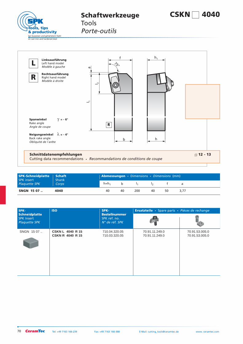
b
a
f
h
l 2
l 1
h1
75°
Spanwinkel γ = - 6°Rake angleAngle de coupe
Neigungswinkel λ = - 4°Back rake angleObliquité de l´arête
SPK- ISO SPK- Ersatzteile Spare parts Pièces de rechangeSchneidplatte BestellnummerSPK Insert SPK ref. no.Plaquette SPK N° de réf. SPK
SNGN 15 07 .. CSKN L 4040 R 15 710.04.320.05 70.91.11.249.0 70.91.53.005.0CSKN R 4040 R 15 710.03.320.05 70.91.11.249.0 70.91.53.005.0
75°
SPK-Schneidplatte Schaft Abmessungen Dimensions Dimensions (mm)SPK insert ShankPlaquette SPK Corps h=h1 b l1 l2 f a
SNGN 15 07 .. 4040 40 40 200 40 50 3,77
SchaftwerkzeugeTools Porte-outils
R
LLinksausführungLeft hand modelModèle à gauche
RRechtsausführungRight hand modelModèle à droite
CSKN 4040
Schnittdatenempfehlungen 12 - 13Cutting data recommendations Recommandations de conditions de coupe
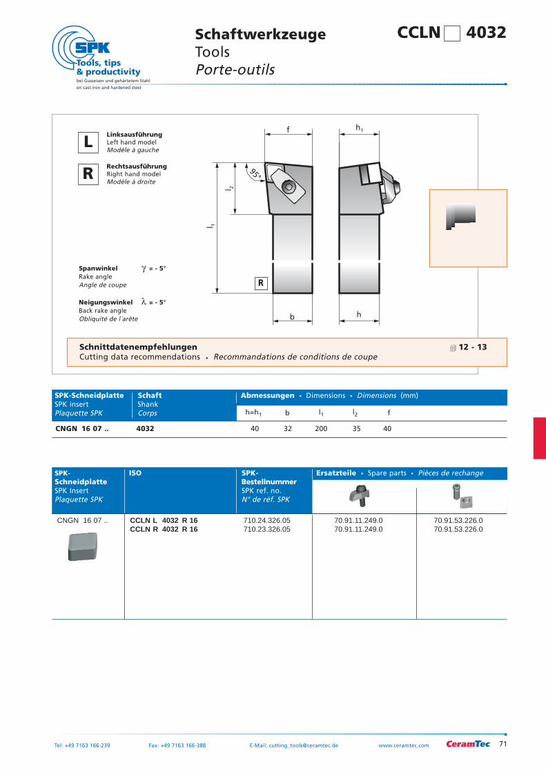
71
bei Gusseisen und gehärtetem Stahl
on cast iron and hardened steel
Tel: +49 7163 166-239 Fax: +49 7163 166-388 E-Mail: [email protected] www.ceramtec.com
b
f
l 2
l 1
h1
h
95°
Spanwinkel γ = - 5°Rake angleAngle de coupe
Neigungswinkel λ = - 5°Back rake angleObliquité de l´arête
SPK- ISO SPK- Ersatzteile Spare parts Pièces de rechangeSchneidplatte BestellnummerSPK Insert SPK ref. no.Plaquette SPK N° de réf. SPK
CNGN 16 07 .. CCLN L 4032 R 16 710.24.326.05 70.91.11.249.0 70.91.53.226.0CCLN R 4032 R 16 710.23.326.05 70.91.11.249.0 70.91.53.226.0
95°
SPK-Schneidplatte Schaft Abmessungen Dimensions Dimensions (mm)SPK insert ShankPlaquette SPK Corps h=h1 b l1 l2 f
CNGN 16 07 .. 4032 40 32 200 35 40
CCLN 4032 SchaftwerkzeugeTools Porte-outils
R
LLinksausführungLeft hand modelModèle à gauche
RRechtsausführungRight hand modelModèle à droite
Schnittdatenempfehlungen 12 - 13Cutting data recommendations Recommandations de conditions de coupe
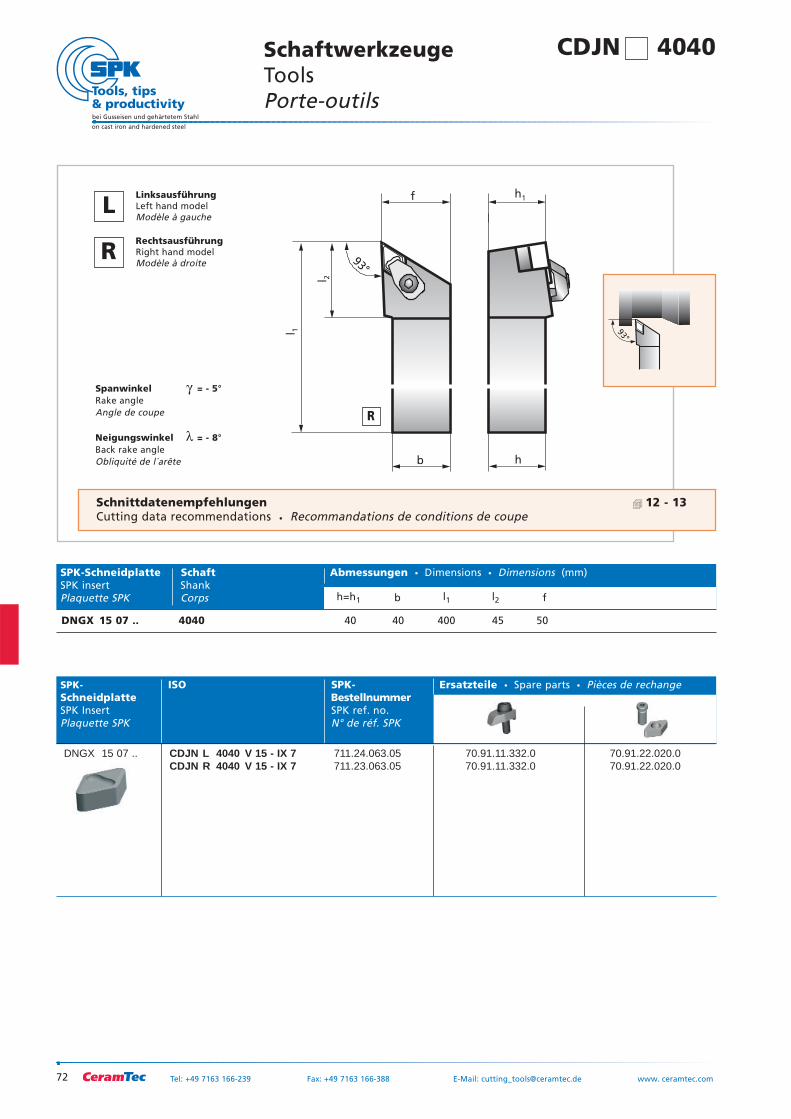
72
bei Gusseisen und gehärtetem Stahl
on cast iron and hardened steel
Tel: +49 7163 166-239 Fax: +49 7163 166-388 E-Mail: [email protected] www. ceramtec.com
b
f
h
l 2
l 1
h1
93°
Spanwinkel γ = - 5°Rake angleAngle de coupe
Neigungswinkel λ = - 8°Back rake angleObliquité de l´arête
SPK- ISO SPK- Ersatzteile Spare parts Pièces de rechangeSchneidplatte BestellnummerSPK Insert SPK ref. no.Plaquette SPK N° de réf. SPK
DNGX 15 07 .. CDJN L 4040 V 15 - IX 7 711.24.063.05 70.91.11.332.0 70.91.22.020.0CDJN R 4040 V 15 - IX 7 711.23.063.05 70.91.11.332.0 70.91.22.020.0
93°
SPK-Schneidplatte Schaft Abmessungen Dimensions Dimensions (mm)SPK insert ShankPlaquette SPK Corps h=h1 b l1 l2 f
DNGX 15 07 .. 4040 40 40 400 45 50
SchaftwerkzeugeTools Porte-outils
R
LLinksausführungLeft hand modelModèle à gauche
RRechtsausführungRight hand modelModèle à droite
CDJN 4040
Schnittdatenempfehlungen 12 - 13Cutting data recommendations Recommandations de conditions de coupe
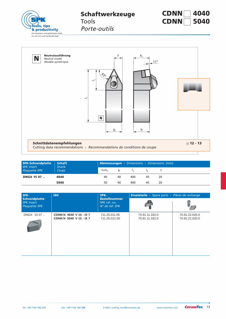
73
bei Gusseisen und gehärtetem Stahl
on cast iron and hardened steel
Tel: +49 7163 166-239 Fax: +49 7163 166-388 E-Mail: [email protected] www.ceramtec.com
b
f
11°
h
l 1
l 2
h1
63°
SPK- ISO SPK- Ersatzteile Spare parts Pièces de rechangeSchneidplatte BestellnummerSPK Insert SPK ref. no.Plaquette SPK N° de réf. SPK
DNGX 15 07 .. CDNN N 4040 V 15 - IX 7 711.25.011.05 70.91.11.332.0 70.91.22.020.0CDNN N 5040 V 15 - IX 7 711.25.012.05 70.91.11.332.0 70.91.22.020.0
63°
SPK-Schneidplatte Schaft Abmessungen Dimensions Dimensions (mm)SPK insert ShankPlaquette SPK Corps h=h1 b l1 l2 f
DNGX 15 07 .. 4040 40 40 400 45 20
5040 50 40 400 45 20
CDNN 4040 SchaftwerkzeugeTools Porte-outils
N
NNeutralausführungNeutral modelModèle symétrique
CDNN 5040
Schnittdatenempfehlungen 12 - 13Cutting data recommendations Recommandations de conditions de coupe
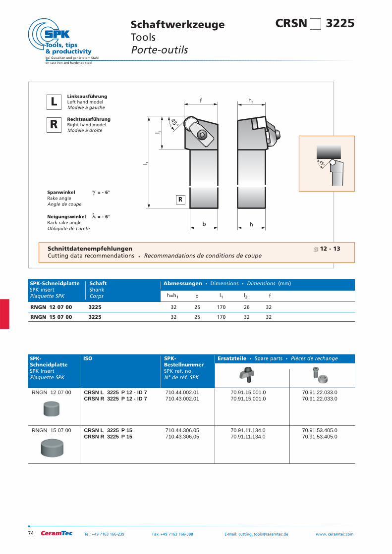
74
bei Gusseisen und gehärtetem Stahl
on cast iron and hardened steel
Tel: +49 7163 166-239 Fax: +49 7163 166-388 E-Mail: [email protected] www. ceramtec.com
b
f
h
l 1
l 2
45°
h1
Spanwinkel γ = - 6°Rake angleAngle de coupe
Neigungswinkel λ = - 6°Back rake angleObliquité de l´arête
SPK- ISO SPK- Ersatzteile Spare parts Pièces de rechangeSchneidplatte BestellnummerSPK Insert SPK ref. no.Plaquette SPK N° de réf. SPK
RNGN 12 07 00 CRSN L 3225 P 12 - ID 7 710.44.002.01 70.91.15.001.0 70.91.22.033.0CRSN R 3225 P 12 - ID 7 710.43.002.01 70.91.15.001.0 70.91.22.033.0
RNGN 15 07 00 CRSN L 3225 P 15 710.44.306.05 70.91.11.134.0 70.91.53.405.0CRSN R 3225 P 15 710.43.306.05 70.91.11.134.0 70.91.53.405.0
45°
SPK-Schneidplatte Schaft Abmessungen Dimensions Dimensions (mm)SPK insert ShankPlaquette SPK Corps h=h1 b l1 l2 f
RNGN 12 07 00 3225 32 25 170 26 32
RNGN 15 07 00 3225 32 25 170 32 32
SchaftwerkzeugeTools Porte-outils
R
LLinksausführungLeft hand modelModèle à gauche
RRechtsausführungRight hand modelModèle à droite
CRSN 3225
Schnittdatenempfehlungen 12 - 13Cutting data recommendations Recommandations de conditions de coupe
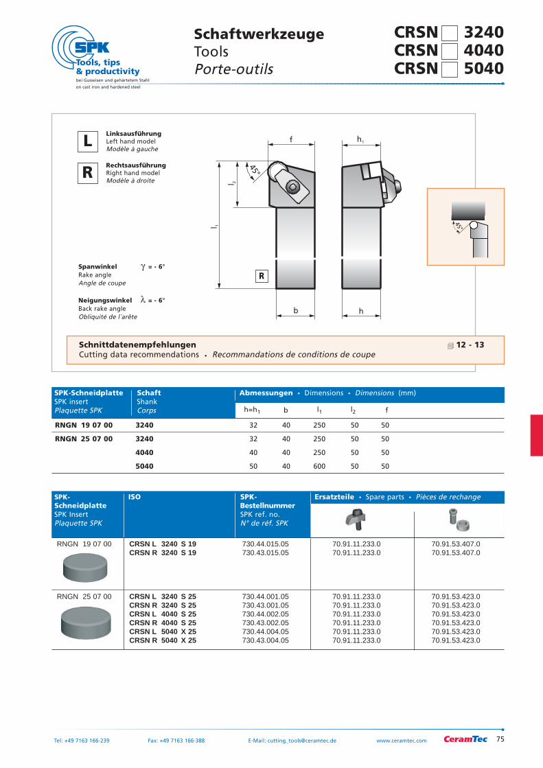
75
bei Gusseisen und gehärtetem Stahl
on cast iron and hardened steel
Tel: +49 7163 166-239 Fax: +49 7163 166-388 E-Mail: [email protected] www.ceramtec.com
b
f
h
l 1
l 2
45°
h1
Spanwinkel γ = - 6°Rake angleAngle de coupe
Neigungswinkel λ = - 6°Back rake angleObliquité de l´arête
SPK- ISO SPK- Ersatzteile Spare parts Pièces de rechangeSchneidplatte BestellnummerSPK Insert SPK ref. no.Plaquette SPK N° de réf. SPK
RNGN 19 07 00 CRSN L 3240 S 19 730.44.015.05 70.91.11.233.0 70.91.53.407.0CRSN R 3240 S 19 730.43.015.05 70.91.11.233.0 70.91.53.407.0
RNGN 25 07 00 CRSN L 3240 S 25 730.44.001.05 70.91.11.233.0 70.91.53.423.0CRSN R 3240 S 25 730.43.001.05 70.91.11.233.0 70.91.53.423.0CRSN L 4040 S 25 730.44.002.05 70.91.11.233.0 70.91.53.423.0CRSN R 4040 S 25 730.43.002.05 70.91.11.233.0 70.91.53.423.0CRSN L 5040 X 25 730.44.004.05 70.91.11.233.0 70.91.53.423.0CRSN R 5040 X 25 730.43.004.05 70.91.11.233.0 70.91.53.423.0
45°
SPK-Schneidplatte Schaft Abmessungen Dimensions Dimensions (mm)SPK insert ShankPlaquette SPK Corps h=h1 b l1 l2 f
RNGN 19 07 00 3240 32 40 250 50 50
RNGN 25 07 00 3240 32 40 250 50 50
4040 40 40 250 50 50
5040 50 40 600 50 50
CRSN 3240 SchaftwerkzeugeTools Porte-outils
R
LLinksausführungLeft hand modelModèle à gauche
RRechtsausführungRight hand modelModèle à droite
CRSN 4040 CRSN 5040
Schnittdatenempfehlungen 12 - 13Cutting data recommendations Recommandations de conditions de coupe
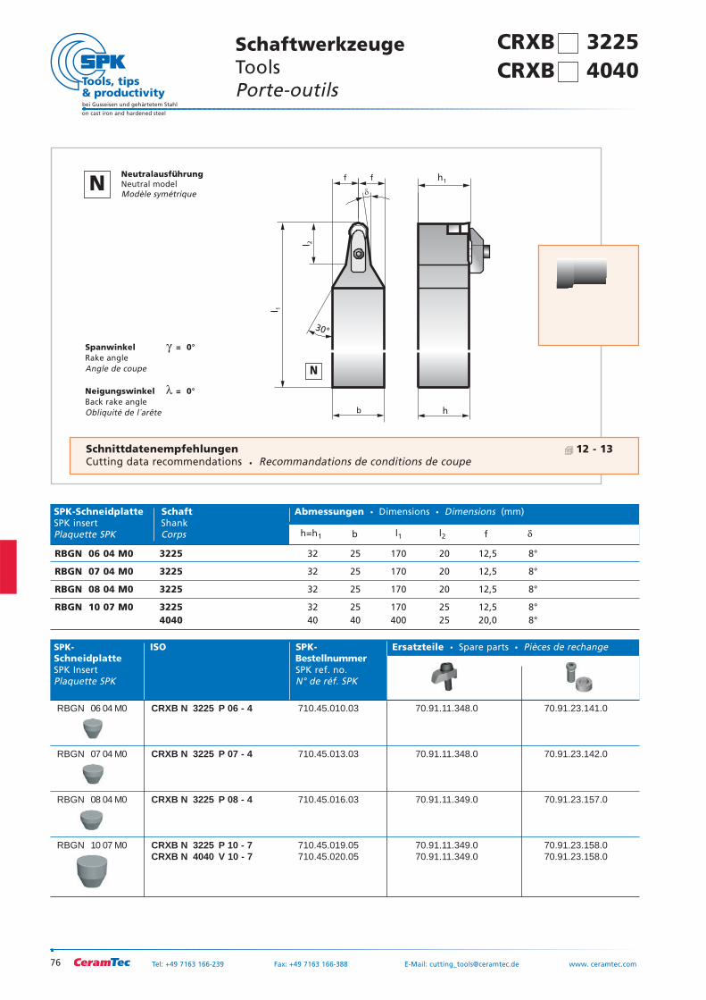
76
bei Gusseisen und gehärtetem Stahl
on cast iron and hardened steel
Tel: +49 7163 166-239 Fax: +49 7163 166-388 E-Mail: [email protected] www. ceramtec.com
b
f f
�
h
l 1
l 2
h1
30°
Spanwinkel γ = 0°Rake angleAngle de coupe
Neigungswinkel λ = 0°Back rake angleObliquité de l´arête
SPK- ISO SPK- Ersatzteile Spare parts Pièces de rechangeSchneidplatte BestellnummerSPK Insert SPK ref. no.Plaquette SPK N° de réf. SPK
RBGN 06 04 M0 CRXB N 3225 P 06 - 4 710.45.010.03 70.91.11.348.0 70.91.23.141.0
RBGN 07 04 M0 CRXB N 3225 P 07 - 4 710.45.013.03 70.91.11.348.0 70.91.23.142.0
RBGN 08 04 M0 CRXB N 3225 P 08 - 4 710.45.016.03 70.91.11.349.0 70.91.23.157.0
RBGN 10 07 M0 CRXB N 3225 P 10 - 7 710.45.019.05 70.91.11.349.0 70.91.23.158.0CRXB N 4040 V 10 - 7 710.45.020.05 70.91.11.349.0 70.91.23.158.0
SPK-Schneidplatte Schaft Abmessungen Dimensions Dimensions (mm)SPK insert ShankPlaquette SPK Corps h=h1 b l1 l2 f δ
RBGN 06 04 M0 3225 32 25 170 20 12,5 8°
RBGN 07 04 M0 3225 32 25 170 20 12,5 8°
RBGN 08 04 M0 3225 32 25 170 20 12,5 8°
RBGN 10 07 M0 3225 32 25 170 25 12,5 8°4040 40 40 400 25 20,0 8°
SchaftwerkzeugeTools Porte-outils
Schnittdatenempfehlungen 12 - 13Cutting data recommendations Recommandations de conditions de coupe
N
NNeutralausführungNeutral modelModèle symétrique
CRXB 3225 CRXB 4040
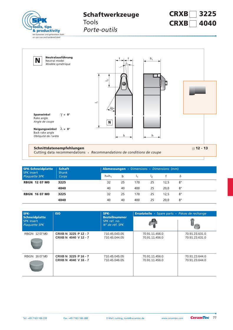
77
bei Gusseisen und gehärtetem Stahl
on cast iron and hardened steel
Tel: +49 7163 166-239 Fax: +49 7163 166-388 E-Mail: [email protected] www.ceramtec.com
b
f f
�
h
l 1
l 2
h1
30°
Spanwinkel γ = 0°Rake angleAngle de coupe
Neigungswinkel λ = 0°Back rake angleObliquité de l´arête
SPK- ISO SPK- Ersatzteile Spare parts Pièces de rechangeSchneidplatte BestellnummerSPK Insert SPK ref. no.Plaquette SPK N° de réf. SPK
RBGN 12 07 M0 CRXB N 3225 P 12 - 7 710.45.043.05 70.91.11.456.0 70.91.23.631.0CRXB N 4040 V 12 - 7 710.45.044.05 70.91.11.456.0 70.91.23.631.0
RBGN 16 07 M0 CRXB N 3225 P 16 - 7 710.45.045.05 70.91.11.456.0 70.91.23.644.0CRXB N 4040 V 16 - 7 710.45.046.05 70.91.11.456.0 70.91.23.644.0
SPK-Schneidplatte Schaft Abmessungen Dimensions Dimensions (mm)SPK insert ShankPlaquette SPK Corps h=h1 b l1 l2 f δ
RBGN 12 07 M0 3225 32 25 170 25 12,5 8°
4040 40 40 400 25 20,0 8°
RBGN 16 07 M0 3225 32 25 170 25 12,5 8°
4040 40 40 400 25 20,0 8°
SchaftwerkzeugeTools Porte-outils
Schnittdatenempfehlungen 12 - 13Cutting data recommendations Recommandations de conditions de coupe
N
NNeutralausführungNeutral modelModèle symétrique
CRXB 3225 CRXB 4040
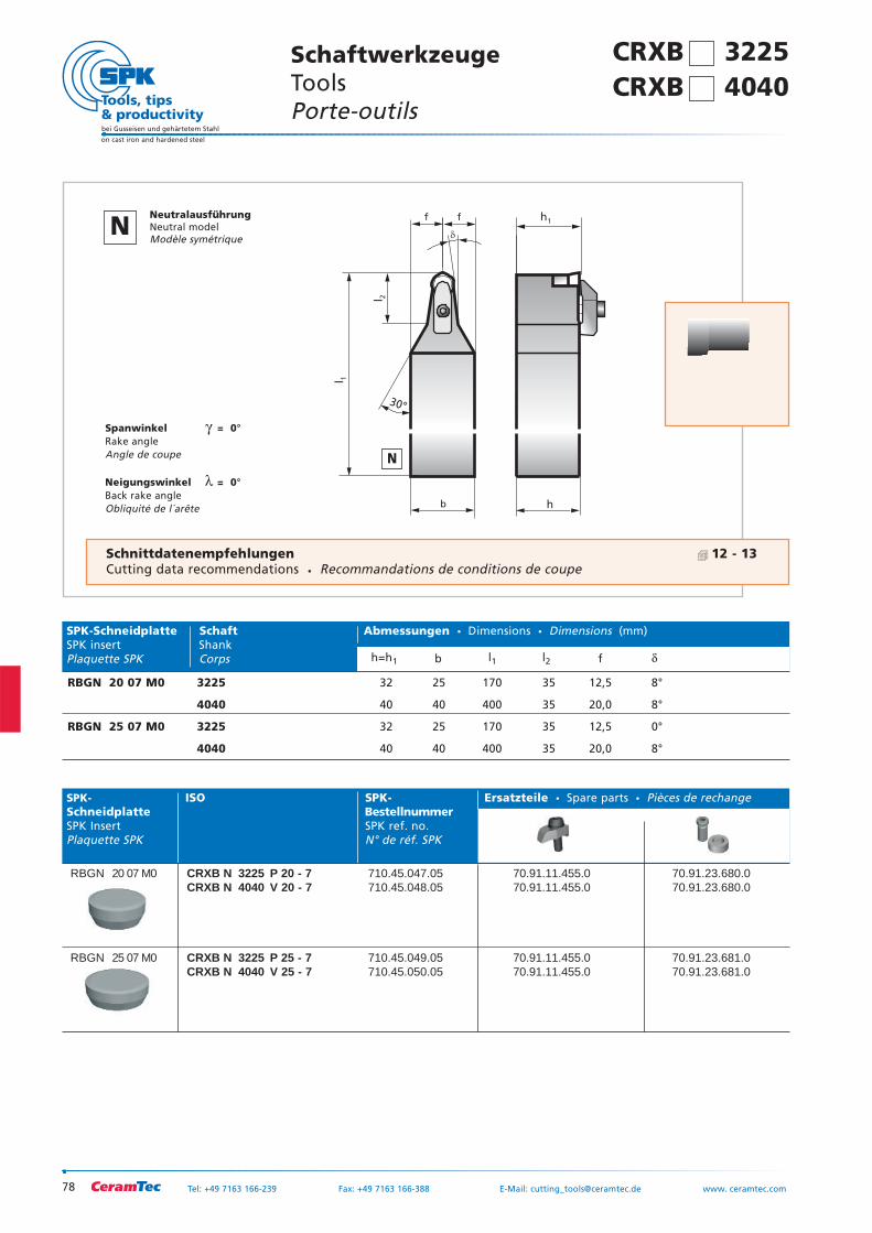
78
bei Gusseisen und gehärtetem Stahl
on cast iron and hardened steel
Tel: +49 7163 166-239 Fax: +49 7163 166-388 E-Mail: [email protected] www. ceramtec.com
b
f f
�
h
l 1
l 2
h1
30°
Spanwinkel γ = 0°Rake angleAngle de coupe
Neigungswinkel λ = 0°Back rake angleObliquité de l´arête
SPK- ISO SPK- Ersatzteile Spare parts Pièces de rechangeSchneidplatte BestellnummerSPK Insert SPK ref. no.Plaquette SPK N° de réf. SPK
RBGN 20 07 M0 CRXB N 3225 P 20 - 7 710.45.047.05 70.91.11.455.0 70.91.23.680.0CRXB N 4040 V 20 - 7 710.45.048.05 70.91.11.455.0 70.91.23.680.0
RBGN 25 07 M0 CRXB N 3225 P 25 - 7 710.45.049.05 70.91.11.455.0 70.91.23.681.0CRXB N 4040 V 25 - 7 710.45.050.05 70.91.11.455.0 70.91.23.681.0
SPK-Schneidplatte Schaft Abmessungen Dimensions Dimensions (mm)SPK insert ShankPlaquette SPK Corps h=h1 b l1 l2 f δ
RBGN 20 07 M0 3225 32 25 170 35 12,5 8°
4040 40 40 400 35 20,0 8°
RBGN 25 07 M0 3225 32 25 170 35 12,5 0°
4040 40 40 400 35 20,0 8°
SchaftwerkzeugeTools Porte-outils
Schnittdatenempfehlungen 12 - 13Cutting data recommendations Recommandations de conditions de coupe
CRXB 3225 CRXB 4040
N
NNeutralausführungNeutral modelModèle symétrique
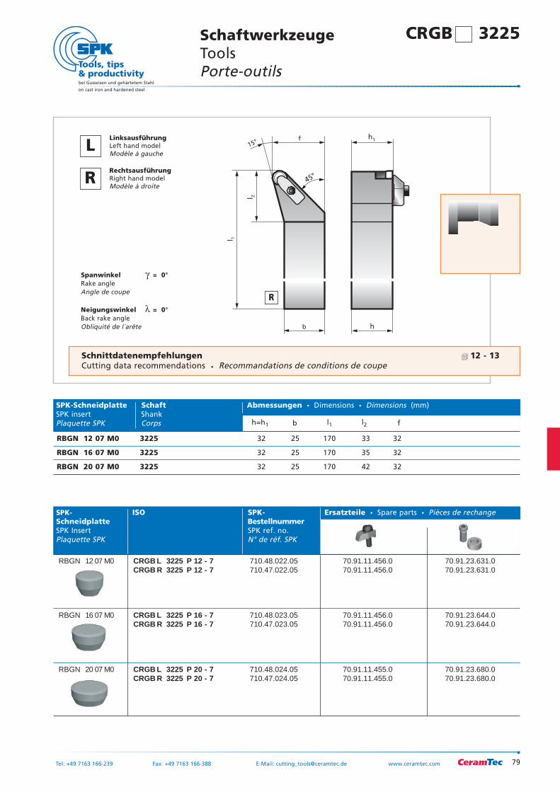
79
bei Gusseisen und gehärtetem Stahl
on cast iron and hardened steel
Tel: +49 7163 166-239 Fax: +49 7163 166-388 E-Mail: [email protected] www.ceramtec.com
l 1
b
f15°
h
l 2
h1
45°
Spanwinkel γ = 0°Rake angleAngle de coupe
Neigungswinkel λ = 0°Back rake angleObliquité de l´arête
SPK- ISO SPK- Ersatzteile Spare parts Pièces de rechangeSchneidplatte BestellnummerSPK Insert SPK ref. no.Plaquette SPK N° de réf. SPK
RBGN 12 07 M0 CRGB L 3225 P 12 - 7 710.48.022.05 70.91.11.456.0 70.91.23.631.0CRGB R 3225 P 12 - 7 710.47.022.05 70.91.11.456.0 70.91.23.631.0
RBGN 16 07 M0 CRGB L 3225 P 16 - 7 710.48.023.05 70.91.11.456.0 70.91.23.644.0CRGB R 3225 P 16 - 7 710.47.023.05 70.91.11.456.0 70.91.23.644.0
RBGN 20 07 M0 CRGB L 3225 P 20 - 7 710.48.024.05 70.91.11.455.0 70.91.23.680.0CRGB R 3225 P 20 - 7 710.47.024.05 70.91.11.455.0 70.91.23.680.0
SPK-Schneidplatte Schaft Abmessungen Dimensions Dimensions (mm)SPK insert ShankPlaquette SPK Corps h=h1 b l1 l2 f
RBGN 12 07 M0 3225 32 25 170 33 32
RBGN 16 07 M0 3225 32 25 170 35 32
RBGN 20 07 M0 3225 32 25 170 42 32
SchaftwerkzeugeTools Porte-outils
R
LLinksausführungLeft hand modelModèle à gauche
RRechtsausführungRight hand modelModèle à droite
Schnittdatenempfehlungen 12 - 13Cutting data recommendations Recommandations de conditions de coupe
CRGB 3225
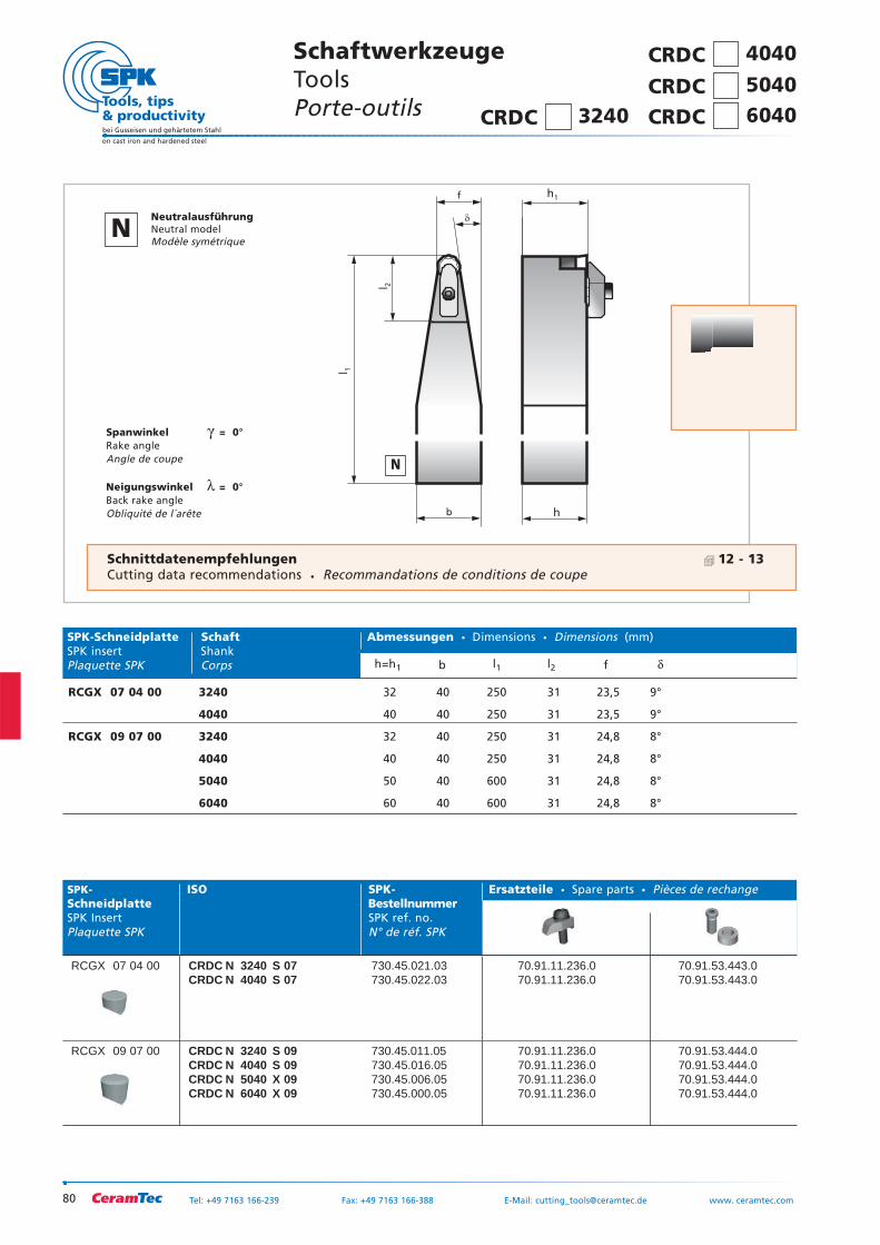
SchaftwerkzeugeTools Porte-outils
80
bei Gusseisen und gehärtetem Stahl
on cast iron and hardened steel
Tel: +49 7163 166-239 Fax: +49 7163 166-388 E-Mail: [email protected] www. ceramtec.com
b
f
�
h
l 1
l 2
h1
Spanwinkel γ = 0°Rake angleAngle de coupe
Neigungswinkel λ = 0°Back rake angleObliquité de l´arête
SPK- ISO SPK- Ersatzteile Spare parts Pièces de rechangeSchneidplatte BestellnummerSPK Insert SPK ref. no.Plaquette SPK N° de réf. SPK
RCGX 07 04 00 CRDC N 3240 S 07 730.45.021.03 70.91.11.236.0 70.91.53.443.0CRDC N 4040 S 07 730.45.022.03 70.91.11.236.0 70.91.53.443.0
RCGX 09 07 00 CRDC N 3240 S 09 730.45.011.05 70.91.11.236.0 70.91.53.444.0CRDC N 4040 S 09 730.45.016.05 70.91.11.236.0 70.91.53.444.0CRDC N 5040 X 09 730.45.006.05 70.91.11.236.0 70.91.53.444.0CRDC N 6040 X 09 730.45.000.05 70.91.11.236.0 70.91.53.444.0
SPK-Schneidplatte Schaft Abmessungen Dimensions Dimensions (mm)SPK insert ShankPlaquette SPK Corps h=h1 b l1 l2 f δ
RCGX 07 04 00 3240 32 40 250 31 23,5 9°
4040 40 40 250 31 23,5 9°
RCGX 09 07 00 3240 32 40 250 31 24,8 8°
4040 40 40 250 31 24,8 8°
5040 50 40 600 31 24,8 8°
6040 60 40 600 31 24,8 8°
N
NNeutralausführungNeutral modelModèle symétrique
Schnittdatenempfehlungen 12 - 13Cutting data recommendations Recommandations de conditions de coupe
CRDC 4040
CRDC 5040
CRDC 6040 CRDC 3240
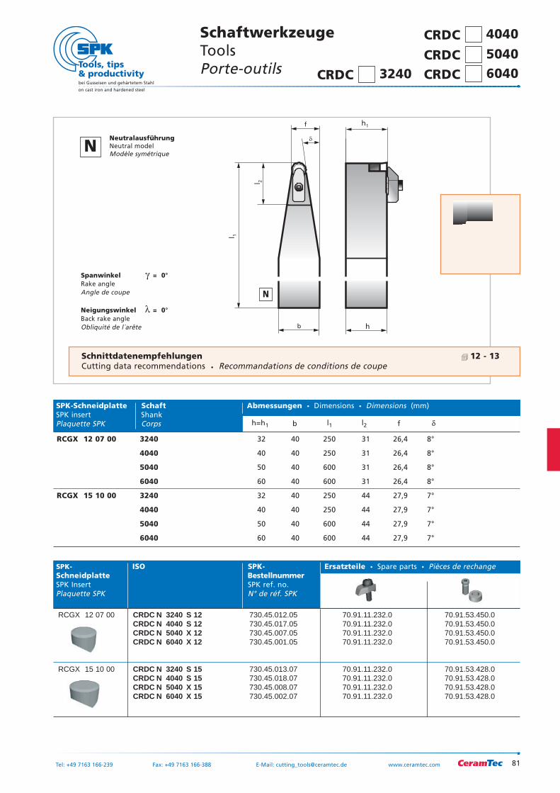
81
bei Gusseisen und gehärtetem Stahl
on cast iron and hardened steel
Tel: +49 7163 166-239 Fax: +49 7163 166-388 E-Mail: [email protected] www.ceramtec.com
b
f
�
h
l 1
l 2
h1
Spanwinkel γ = 0°Rake angleAngle de coupe
Neigungswinkel λ = 0°Back rake angleObliquité de l´arête
SPK- ISO SPK- Ersatzteile Spare parts Pièces de rechangeSchneidplatte BestellnummerSPK Insert SPK ref. no.Plaquette SPK N° de réf. SPK
RCGX 12 07 00 CRDC N 3240 S 12 730.45.012.05 70.91.11.232.0 70.91.53.450.0CRDC N 4040 S 12 730.45.017.05 70.91.11.232.0 70.91.53.450.0CRDC N 5040 X 12 730.45.007.05 70.91.11.232.0 70.91.53.450.0CRDC N 6040 X 12 730.45.001.05 70.91.11.232.0 70.91.53.450.0
RCGX 15 10 00 CRDC N 3240 S 15 730.45.013.07 70.91.11.232.0 70.91.53.428.0CRDC N 4040 S 15 730.45.018.07 70.91.11.232.0 70.91.53.428.0CRDC N 5040 X 15 730.45.008.07 70.91.11.232.0 70.91.53.428.0CRDC N 6040 X 15 730.45.002.07 70.91.11.232.0 70.91.53.428.0
SPK-Schneidplatte Schaft Abmessungen Dimensions Dimensions (mm)SPK insert ShankPlaquette SPK Corps h=h1 b l1 l2 f δ
RCGX 12 07 00 3240 32 40 250 31 26,4 8°
4040 40 40 250 31 26,4 8°
5040 50 40 600 31 26,4 8°
6040 60 40 600 31 26,4 8°
RCGX 15 10 00 3240 32 40 250 44 27,9 7°
4040 40 40 250 44 27,9 7°
5040 50 40 600 44 27,9 7°
6040 60 40 600 44 27,9 7°
SchaftwerkzeugeTools Porte-outils
Schnittdatenempfehlungen 12 - 13Cutting data recommendations Recommandations de conditions de coupe
N
NNeutralausführungNeutral modelModèle symétrique
CRDC 4040
CRDC 5040
CRDC 6040 CRDC 3240
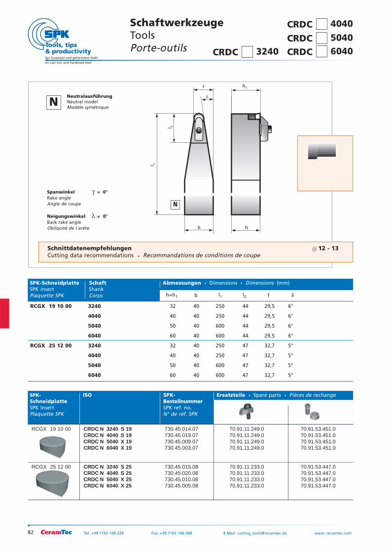
82
bei Gusseisen und gehärtetem Stahl
on cast iron and hardened steel
Tel: +49 7163 166-239 Fax: +49 7163 166-388 E-Mail: [email protected] www. ceramtec.com
b
f
�
h
l 1
l 2
h1
Spanwinkel γ = 0°Rake angleAngle de coupe
Neigungswinkel λ = 0°Back rake angleObliquité de l´arête
SPK- ISO SPK- Ersatzteile Spare parts Pièces de rechangeSchneidplatte BestellnummerSPK Insert SPK ref. no.Plaquette SPK N° de réf. SPK
RCGX 19 10 00 CRDC N 3240 S 19 730.45.014.07 70.91.11.249.0 70.91.53.451.0CRDC N 4040 S 19 730.45.019.07 70.91.11.249.0 70.91.53.451.0CRDC N 5040 X 19 730.45.009.07 70.91.11.249.0 70.91.53.451.0CRDC N 6040 X 19 730.45.003.07 70.91.11.249.0 70.91.53.451.0
RCGX 25 12 00 CRDC N 3240 S 25 730.45.015.08 70.91.11.233.0 70.91.53.447.0CRDC N 4040 S 25 730.45.020.08 70.91.11.233.0 70.91.53.447.0CRDC N 5040 X 25 730.45.010.08 70.91.11.233.0 70.91.53.447.0CRDC N 6040 X 25 730.45.005.08 70.91.11.233.0 70.91.53.447.0
SPK-Schneidplatte Schaft Abmessungen Dimensions Dimensions (mm)SPK insert ShankPlaquette SPK Corps h=h1 b l1 l2 f δ
RCGX 19 10 00 3240 32 40 250 44 29,5 6°
4040 40 40 250 44 29,5 6°
5040 50 40 600 44 29,5 6°
6040 60 40 600 44 29,5 6°
RCGX 25 12 00 3240 32 40 250 47 32,7 5°
4040 40 40 250 47 32,7 5°
5040 50 40 600 47 32,7 5°
6040 60 40 600 47 32,7 5°
SchaftwerkzeugeTools Porte-outils
Schnittdatenempfehlungen 12 - 13Cutting data recommendations Recommandations de conditions de coupe
N
NNeutralausführungNeutral modelModèle symétrique
CRDC 4040
CRDC 5040
CRDC 6040 CRDC 3240
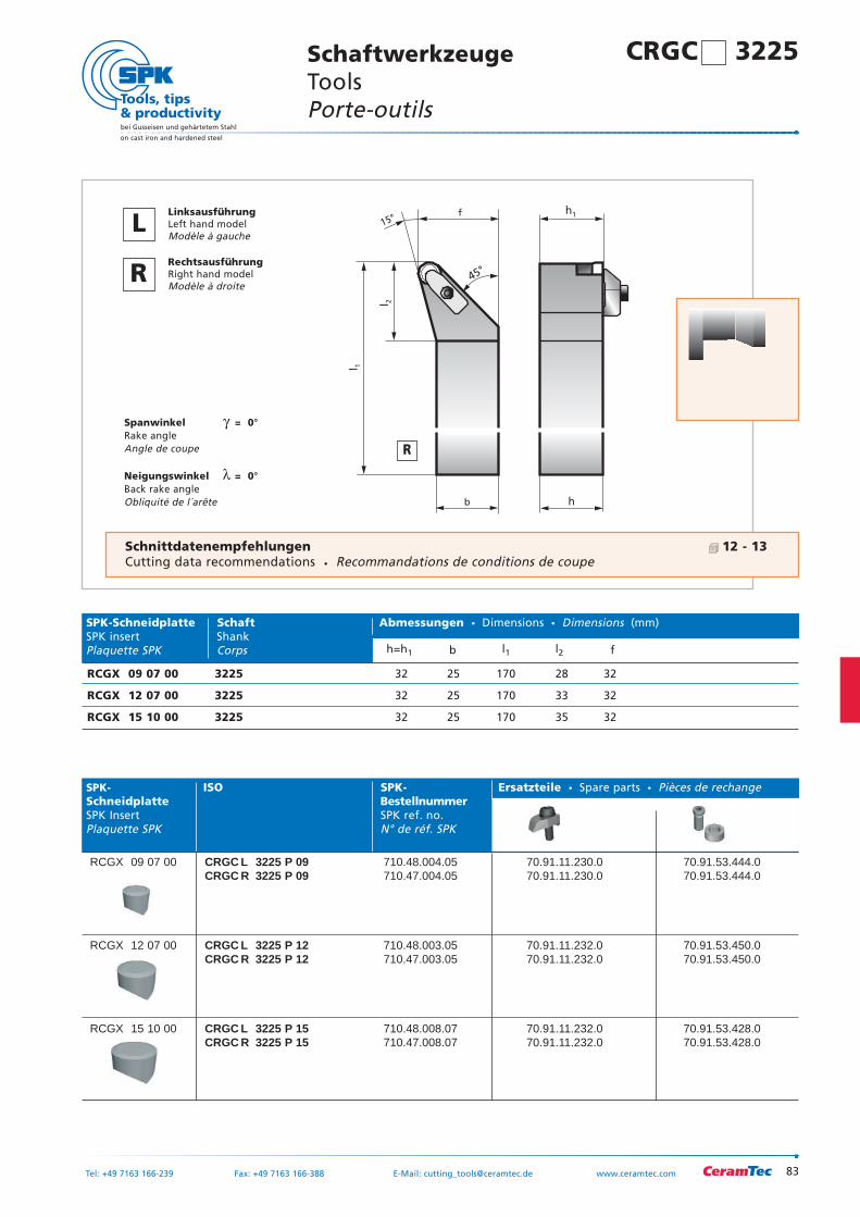
83
bei Gusseisen und gehärtetem Stahl
on cast iron and hardened steel
Tel: +49 7163 166-239 Fax: +49 7163 166-388 E-Mail: [email protected] www.ceramtec.com
l 1
b
f15°
h
l 2
h1
45°
Spanwinkel γ = 0°Rake angleAngle de coupe
Neigungswinkel λ = 0°Back rake angleObliquité de l´arête
SPK- ISO SPK- Ersatzteile Spare parts Pièces de rechangeSchneidplatte BestellnummerSPK Insert SPK ref. no.Plaquette SPK N° de réf. SPK
RCGX 09 07 00 CRGC L 3225 P 09 710.48.004.05 70.91.11.230.0 70.91.53.444.0CRGC R 3225 P 09 710.47.004.05 70.91.11.230.0 70.91.53.444.0
RCGX 12 07 00 CRGC L 3225 P 12 710.48.003.05 70.91.11.232.0 70.91.53.450.0CRGC R 3225 P 12 710.47.003.05 70.91.11.232.0 70.91.53.450.0
RCGX 15 10 00 CRGC L 3225 P 15 710.48.008.07 70.91.11.232.0 70.91.53.428.0CRGC R 3225 P 15 710.47.008.07 70.91.11.232.0 70.91.53.428.0
SPK-Schneidplatte Schaft Abmessungen Dimensions Dimensions (mm)SPK insert ShankPlaquette SPK Corps h=h1 b l1 l2 f
RCGX 09 07 00 3225 32 25 170 28 32
RCGX 12 07 00 3225 32 25 170 33 32
RCGX 15 10 00 3225 32 25 170 35 32
SchaftwerkzeugeTools Porte-outils
Schnittdatenempfehlungen 12 - 13Cutting data recommendations Recommandations de conditions de coupe
R
LLinksausführungLeft hand modelModèle à gauche
RRechtsausführungRight hand modelModèle à droite
CRGC 3225
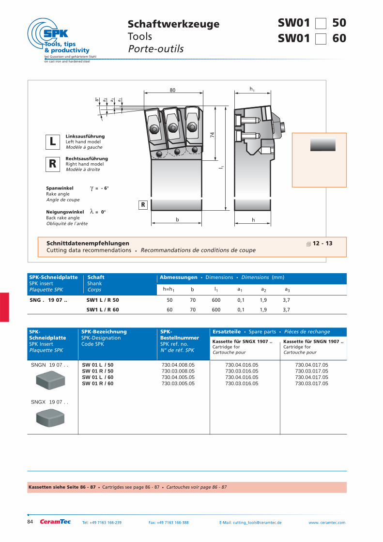
SW01 50SW01 60
84
bei Gusseisen und gehärtetem Stahl
on cast iron and hardened steel
Tel: +49 7163 166-239 Fax: +49 7163 166-388 E-Mail: [email protected] www. ceramtec.com
80
74
l 1
h1
b h
a1
a2
a38°
Spanwinkel γ = - 6°Rake angleAngle de coupe
Neigungswinkel λ = 0°Back rake angleObliquité de l´arête
SPK- SPK-Bezeichnung SPK- Ersatzteile Spare parts Pièces de rechangeSchneidplatte SPK-Designation BestellnummerSPK Insert Code SPK SPK ref. no.Plaquette SPK N° de réf. SPK
SNGN 19 07 . . SW 01 L / 50 730.04.008.05 730.04.016.05 730.04.017.05SW 01 R / 50 730.03.008.05 730.03.016.05 730.03.017.05SW 01 L / 60 730.04.005.05 730.04.016.05 730.04.017.05SW 01 R / 60 730.03.005.05 730.03.016.05 730.03.017.05
SNGX 19 07 . .
SPK-Schneidplatte Schaft Abmessungen Dimensions Dimensions (mm)SPK insert ShankPlaquette SPK Corps h=h1 b l1 a1 a2 a3
SNG . 19 07 .. SW1 L / R 50 50 70 600 0,1 1,9 3,7
SW1 L / R 60 60 70 600 0,1 1,9 3,7
SchaftwerkzeugeTools Porte-outils
R
LLinksausführungLeft hand modelModèle à gauche
RRechtsausführungRight hand modelModèle à droite
Schnittdatenempfehlungen 12 - 13Cutting data recommendations Recommandations de conditions de coupe
Kassette für SNGX 1907 ..Cartridge forCartouche pour
Kassette für SNGN 1907 ..Cartridge forCartouche pour
Kassetten siehe Seite 86 - 87 Cartrigdes see page 86 - 87 Cartouches voir page 86 - 87
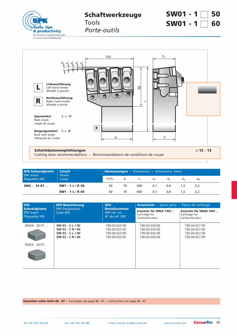
85
bei Gusseisen und gehärtetem Stahl
on cast iron and hardened steel
Tel: +49 7163 166-239 Fax: +49 7163 166-388 E-Mail: [email protected] www.ceramtec.com
103
88
l 1
h1
b h
a1
a2
a3
a44°
Spanwinkel γ = - 6°Rake angleAngle de coupe
Neigungswinkel λ = 0°Back rake angleObliquité de l´arête
SPK- SPK-Bezeichnung SPK- Ersatzteile Spare parts Pièces de rechangeSchneidplatte SPK-Designation BestellnummerSPK Insert Code SPK SPK ref. no.Plaquette SPK N° de réf. SPK
SNGN 19 07 . . SW 01 - 1 L / 50 730.04.012.05 730.04.016.05 730.04.017.05SW 01 - 1 R / 50 730.03.012.05 730.03.016.05 730.03.017.05SW 01 - 1 L / 60 730.04.013.05 730.04.016.05 730.04.017.05SW 01 - 1 R / 60 730.03.013.05 730.03.016.05 730.03.017.05
SNGX 19 07 . .
SPK-Schneidplatte Schaft Abmessungen Dimensions Dimensions (mm)SPK insert ShankPlaquette SPK Corps h=h1 b l1 a1 a2 a3 a4
SNG . 19 07 .. SW1 - 1 L / R 50 50 70 600 0,1 0,8 1,5 2,2
SW1 - 1 L / R 60 60 70 600 0,1 0,8 1,5 2,2
SchaftwerkzeugeTools Porte-outils
R
LLinksausführungLeft hand modelModèle à gauche
RRechtsausführungRight hand modelModèle à droite
Schnittdatenempfehlungen 12 - 13Cutting data recommendations Recommandations de conditions de coupe
Kassette für SNGX 1907 ..Cartridge forCartouche pour
Kassette für SNGN 1907 ..Cartridge forCartouche pour
Kassetten siehe Seite 86 - 87 Cartrigdes see page 86 - 87 Cartouches voir page 86 - 87
SW01 - 1 50SW01 - 1 60
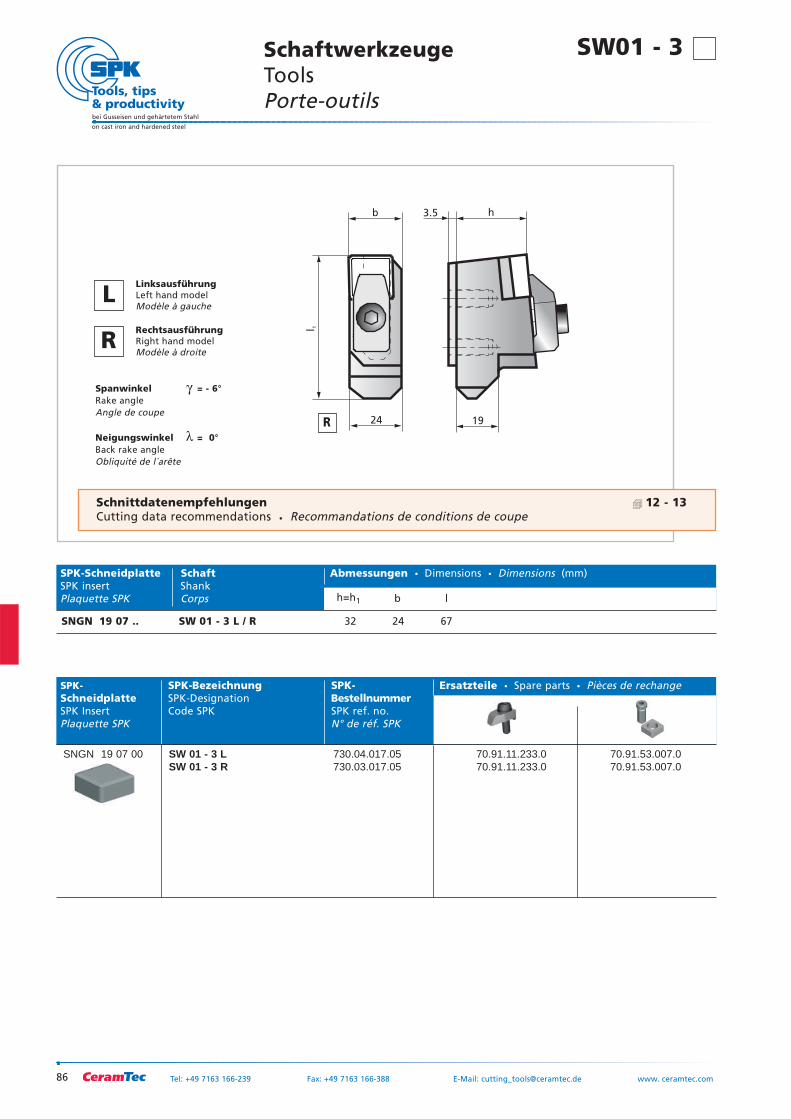
86
bei Gusseisen und gehärtetem Stahl
on cast iron and hardened steel
Tel: +49 7163 166-239 Fax: +49 7163 166-388 E-Mail: [email protected] www. ceramtec.com
24 19
3.5b h
l 1
Spanwinkel γ = - 6°Rake angleAngle de coupe
Neigungswinkel λ = 0°Back rake angleObliquité de l´arête
SchaftwerkzeugeTools Porte-outils
R
LLinksausführungLeft hand modelModèle à gauche
RRechtsausführungRight hand modelModèle à droite
Schnittdatenempfehlungen 12 - 13Cutting data recommendations Recommandations de conditions de coupe
SPK- SPK-Bezeichnung SPK- Ersatzteile Spare parts Pièces de rechangeSchneidplatte SPK-Designation BestellnummerSPK Insert Code SPK SPK ref. no.Plaquette SPK N° de réf. SPK
SNGN 19 07 00 SW 01 - 3 L 730.04.017.05 70.91.11.233.0 70.91.53.007.0SW 01 - 3 R 730.03.017.05 70.91.11.233.0 70.91.53.007.0
SPK-Schneidplatte Schaft Abmessungen Dimensions Dimensions (mm)SPK insert ShankPlaquette SPK Corps h=h1 b l
SNGN 19 07 .. SW 01 - 3 L / R 32 24 67
SW01 - 3
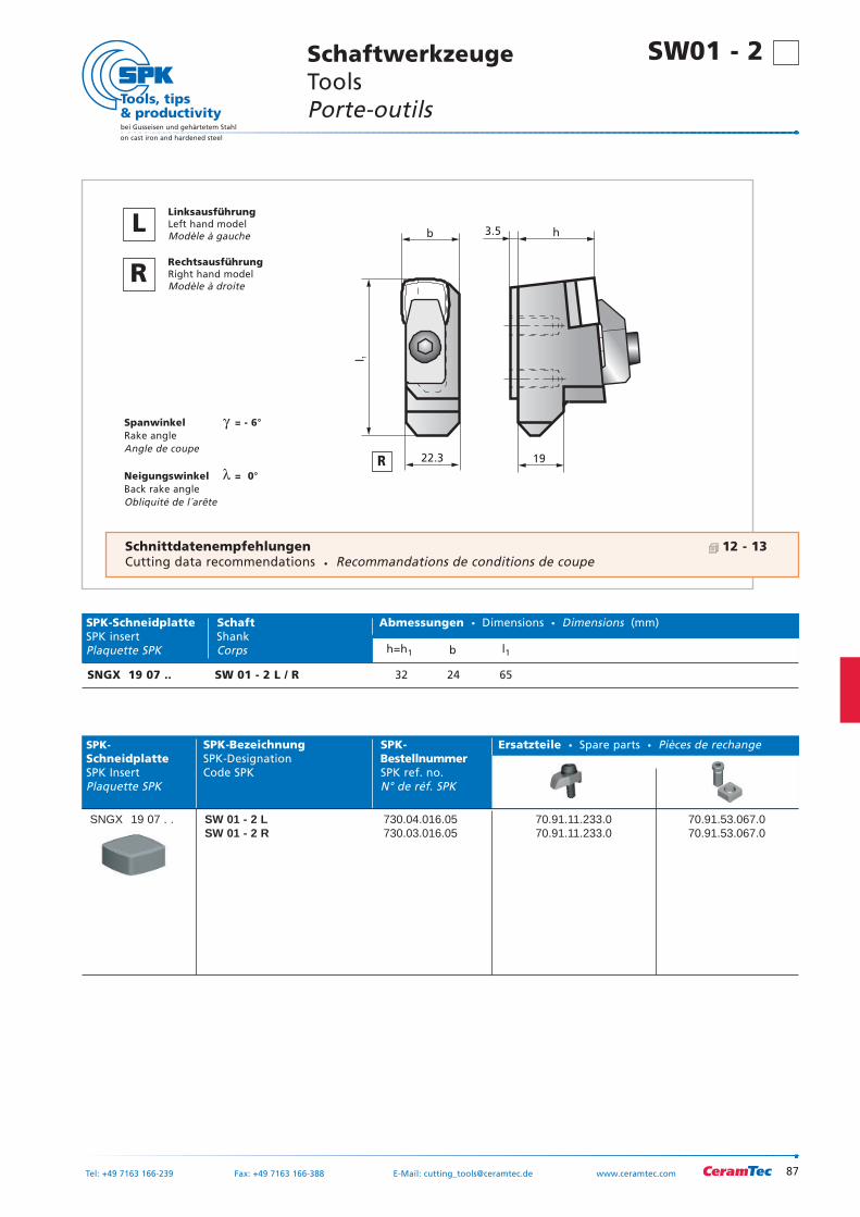
87
bei Gusseisen und gehärtetem Stahl
on cast iron and hardened steel
Tel: +49 7163 166-239 Fax: +49 7163 166-388 E-Mail: [email protected] www.ceramtec.com
22.3 19
3.5b h
l 1
Spanwinkel γ = - 6°Rake angleAngle de coupe
Neigungswinkel λ = 0°Back rake angleObliquité de l´arête
SPK- SPK-Bezeichnung SPK- Ersatzteile Spare parts Pièces de rechangeSchneidplatte SPK-Designation BestellnummerSPK Insert Code SPK SPK ref. no.Plaquette SPK N° de réf. SPK
SNGX 19 07 . . SW 01 - 2 L 730.04.016.05 70.91.11.233.0 70.91.53.067.0SW 01 - 2 R 730.03.016.05 70.91.11.233.0 70.91.53.067.0
SPK-Schneidplatte Schaft Abmessungen Dimensions Dimensions (mm)SPK insert ShankPlaquette SPK Corps h=h1 b l1
SNGX 19 07 .. SW 01 - 2 L / R 32 24 65
SW01 - 2 SchaftwerkzeugeTools Porte-outils
R
LLinksausführungLeft hand modelModèle à gauche
RRechtsausführungRight hand modelModèle à droite
Schnittdatenempfehlungen 12 - 13Cutting data recommendations Recommandations de conditions de coupe
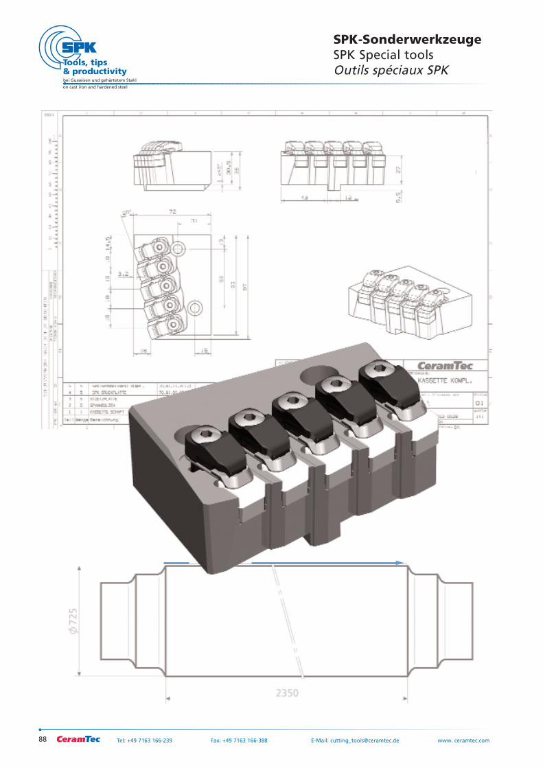
88
bei Gusseisen und gehärtetem Stahl
on cast iron and hardened steel
Tel: +49 7163 166-239 Fax: +49 7163 166-388 E-Mail: [email protected] www. ceramtec.com
SPK-SonderwerkzeugeSPK Special toolsOutils spéciaux SPK
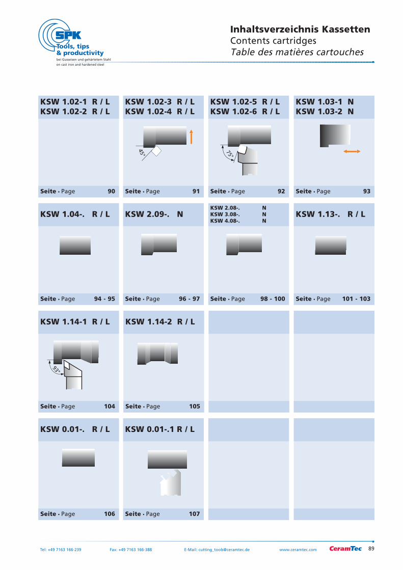
89
bei Gusseisen und gehärtetem Stahl
on cast iron and hardened steel
Tel: +49 7163 166-239 Fax: +49 7163 166-388 E-Mail: [email protected] www.ceramtec.com
KSW 0.01-.1 R / L
Seite Page 107
KSW 0.01-. R / L
Seite Page 106
KSW 2.09-. N
Seite Page 96 - 97
93°
KSW 1.14-1 R / L
Seite Page 104
KSW 1.04-. R / L
Seite Page 94 - 95
KSW 1.13-. R / L
Seite Page 101 - 103
KSW 2.08-. NKSW 3.08-. NKSW 4.08-. N
Seite Page 98 - 100
63°
KSW 1.14-2 R / L
Seite Page 105
Inhaltsverzeichnis KassettenContents cartridgesTable des matières cartouches
75°
KSW 1.02-5 R / LKSW 1.02-6 R / L
Seite Page 92
45°
KSW 1.02-3 R / LKSW 1.02-4 R / L
Seite Page 91
�
KSW 1.02-1 R / LKSW 1.02-2 R / L
Seite Page 90
45°
KSW 1.03-1 NKSW 1.03-2 N
Seite Page 93
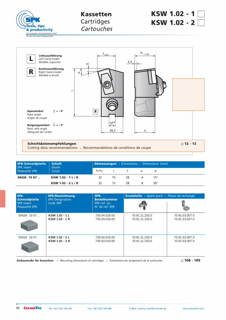
90
bei Gusseisen und gehärtetem Stahl
on cast iron and hardened steel
Tel: +49 7163 166-239 Fax: +49 7163 166-388 E-Mail: [email protected] www.ceramtec.com
0,08
34,5 h
10
3,3
f
a
H8
-0,08
l
h1
�
Spanwinkel γ = - 6°Rake angleAngle de coupe
Neigungswinkel λ = - 3°Back rake angleObliquité de l´arête
SPK- SPK-Bezeichnung SPK- Ersatzteile Spare parts Pièces de rechangeSchneidplatte SPK-Designation BestellnummerSPK Insert Code SPK SPK ref. no.Plaquette SPK N° de réf. SPK
SNGN 19 07 .. KSW 1.02 - 1 L 730.04.018.05 70.91.11.233.0 70.91.53.007.0KSW 1.02 - 1 R 730.03.018.05 70.91.11.233.0 70.91.53.007.0
SNGN 19 07 .. KSW 1.02 - 2 L 730.04.019.05 70.91.11.233.0 70.91.53.007.0KSW 1.02 - 2 R 730.03.019.05 70.91.11.233.0 70.91.53.007.0
�
SPK-Schneidplatte Schaft Abmessungen Dimensions Dimensions (mm)SPK insert ShankPlaquette SPK Corps h=h1 l f a κ
SNGN 19 07 .. KSW 1.02 - 1 L / R 32 75 28 4 15°
KSW 1.02 - 2 L / R 32 75 28 8 30°
KSW 1.02 - 1 KassettenCartridgesCartouches
R
LLinksausführungLeft hand modelModèle à gauche
RRechtsausführungRight hand modelModèle à droite
KSW 1.02 - 2
Schnittdatenempfehlungen 12 - 13Cutting data recommendations Recommandations de conditions de coupe
Einbaumaße für Kassetten Mounting dimensions of cartridges Dimensions du longement de la cartouche 108 - 109
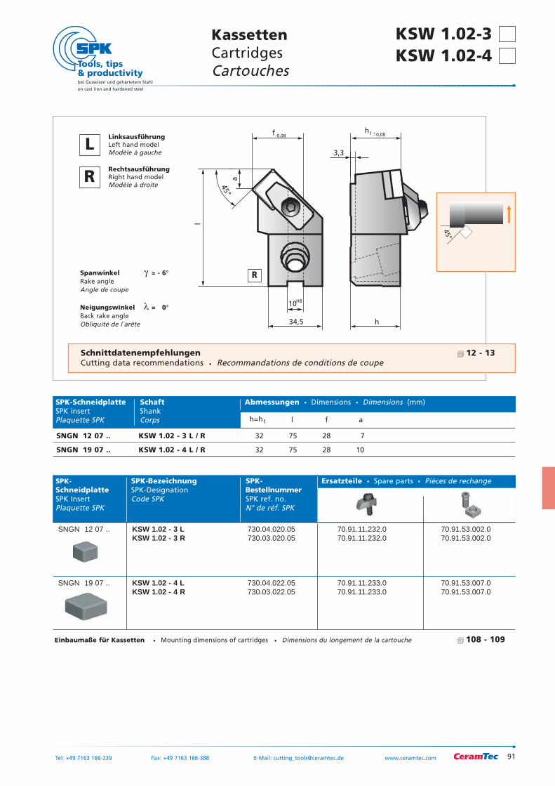
91
bei Gusseisen und gehärtetem Stahl
on cast iron and hardened steel
Tel: +49 7163 166-239 Fax: +49 7163 166-388 E-Mail: [email protected] www.ceramtec.com
KassettenCartridgesCartouches
KSW 1.02-3 KSW 1.02-4
34,5 h
10
3,3
f
a
H8
-0,08 0,08
l
h1
45°
Spanwinkel γ = - 6°Rake angleAngle de coupe
Neigungswinkel λ = 0°Back rake angleObliquité de l´arête
SPK- SPK-Bezeichnung SPK- Ersatzteile Spare parts Pièces de rechangeSchneidplatte SPK-Designation BestellnummerSPK Insert Code SPK SPK ref. no.Plaquette SPK N° de réf. SPK
SNGN 12 07 .. KSW 1.02 - 3 L 730.04.020.05 70.91.11.232.0 70.91.53.002.0KSW 1.02 - 3 R 730.03.020.05 70.91.11.232.0 70.91.53.002.0
SNGN 19 07 .. KSW 1.02 - 4 L 730.04.022.05 70.91.11.233.0 70.91.53.007.0KSW 1.02 - 4 R 730.03.022.05 70.91.11.233.0 70.91.53.007.0
45°
SPK-Schneidplatte Schaft Abmessungen Dimensions Dimensions (mm)SPK insert ShankPlaquette SPK Corps h=h1 l f a
SNGN 12 07 .. KSW 1.02 - 3 L / R 32 75 28 7
SNGN 19 07 .. KSW 1.02 - 4 L / R 32 75 28 10
R
LLinksausführungLeft hand modelModèle à gauche
RRechtsausführungRight hand modelModèle à droite
Schnittdatenempfehlungen 12 - 13Cutting data recommendations Recommandations de conditions de coupe
Einbaumaße für Kassetten Mounting dimensions of cartridges Dimensions du longement de la cartouche 108 - 109
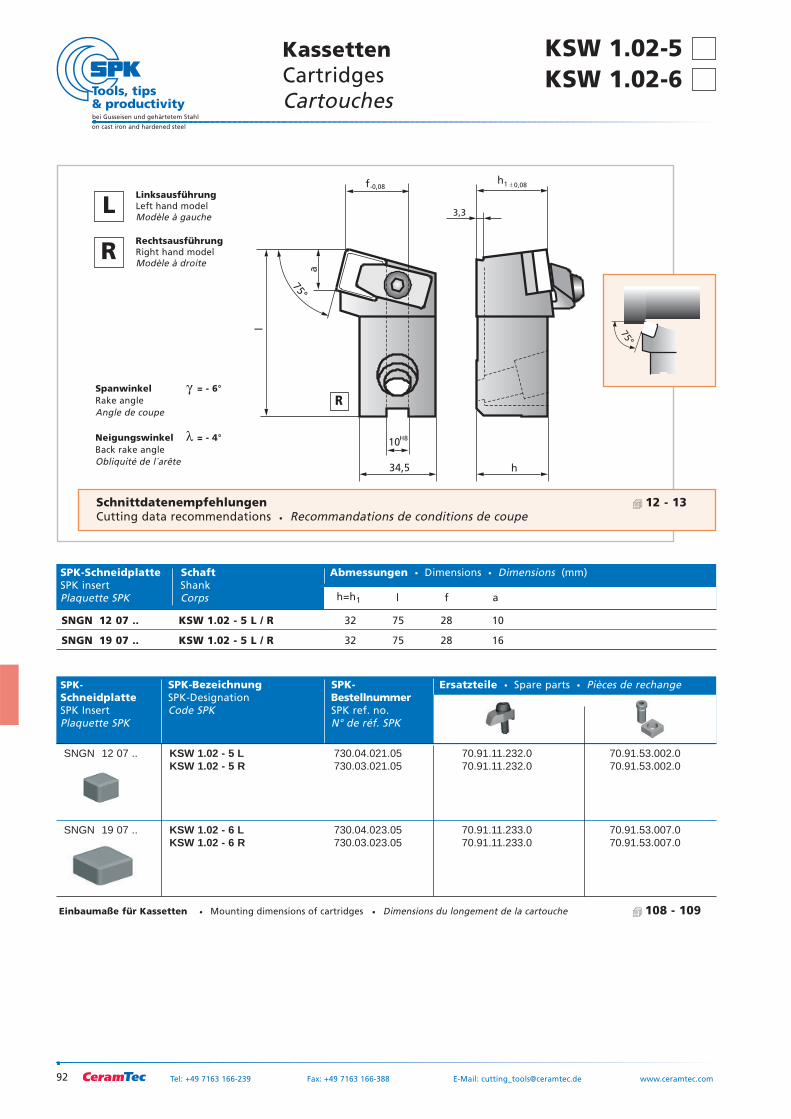
92
bei Gusseisen und gehärtetem Stahl
on cast iron and hardened steel
Tel: +49 7163 166-239 Fax: +49 7163 166-388 E-Mail: [email protected] www.ceramtec.com
34,5 h
10
3,3
f
a
H8
-0,08 0,08
l
h1
75°
Spanwinkel γ = - 6°Rake angleAngle de coupe
Neigungswinkel λ = - 4°Back rake angleObliquité de l´arête
SPK- SPK-Bezeichnung SPK- Ersatzteile Spare parts Pièces de rechangeSchneidplatte SPK-Designation BestellnummerSPK Insert Code SPK SPK ref. no.Plaquette SPK N° de réf. SPK
SNGN 12 07 .. KSW 1.02 - 5 L 730.04.021.05 70.91.11.232.0 70.91.53.002.0KSW 1.02 - 5 R 730.03.021.05 70.91.11.232.0 70.91.53.002.0
SNGN 19 07 .. KSW 1.02 - 6 L 730.04.023.05 70.91.11.233.0 70.91.53.007.0KSW 1.02 - 6 R 730.03.023.05 70.91.11.233.0 70.91.53.007.0
75°
SPK-Schneidplatte Schaft Abmessungen Dimensions Dimensions (mm)SPK insert ShankPlaquette SPK Corps h=h1 l f a
SNGN 12 07 .. KSW 1.02 - 5 L / R 32 75 28 10
SNGN 19 07 .. KSW 1.02 - 5 L / R 32 75 28 16
KSW 1.02-5 KassettenCartridgesCartouches
R
LLinksausführungLeft hand modelModèle à gauche
RRechtsausführungRight hand modelModèle à droite
KSW 1.02-6
Schnittdatenempfehlungen 12 - 13Cutting data recommendations Recommandations de conditions de coupe
Einbaumaße für Kassetten Mounting dimensions of cartridges Dimensions du longement de la cartouche 108 - 109
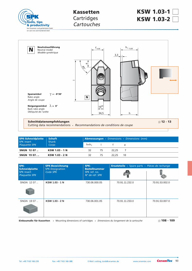
93
bei Gusseisen und gehärtetem Stahl
on cast iron and hardened steel
Tel: +49 7163 166-239 Fax: +49 7163 166-388 E-Mail: [email protected] www.ceramtec.com
KassettenCartridgesCartouches
KSW 1.03-1 KSW 1.03-2
34,5 h
10
3,3
f
a
H8
-0,08 0,08
l
h1
45°
Spanwinkel γ = - 8°30’Rake angleAngle de coupe
Neigungswinkel λ = 0°Back rake angleObliquité de l´arête
SPK- SPK-Bezeichnung SPK- Ersatzteile Spare parts Pièces de rechangeSchneidplatte SPK-Designation BestellnummerSPK Insert Code SPK SPK ref. no.Plaquette SPK N° de réf. SPK
SNGN 12 07 .. KSW 1.03 - 1 N 730.06.000.05 70.91.11.232.0 70.91.53.002.0
SNGN 19 07 .. KSW 1.03 - 2 N 730.06.001.05 70.91.11.233.0 70.91.53.007.0
45°
SPK-Schneidplatte Schaft Abmessungen Dimensions Dimensions (mm)SPK insert ShankPlaquette SPK Corps h=h1 l f a
SNGN 12 07 .. KSW 1.03 - 1 N 32 75 22,25 7
SNGN 19 07. .. KSW 1.03 - 2 N 32 75 22,25 10
N
NNeutralausführungNeutral modelModèle symétrique
Schnittdatenempfehlungen 12 - 13Cutting data recommendations Recommandations de conditions de coupe
Einbaumaße für Kassetten Mounting dimensions of cartridges Dimensions du longement de la cartouche 108 - 109
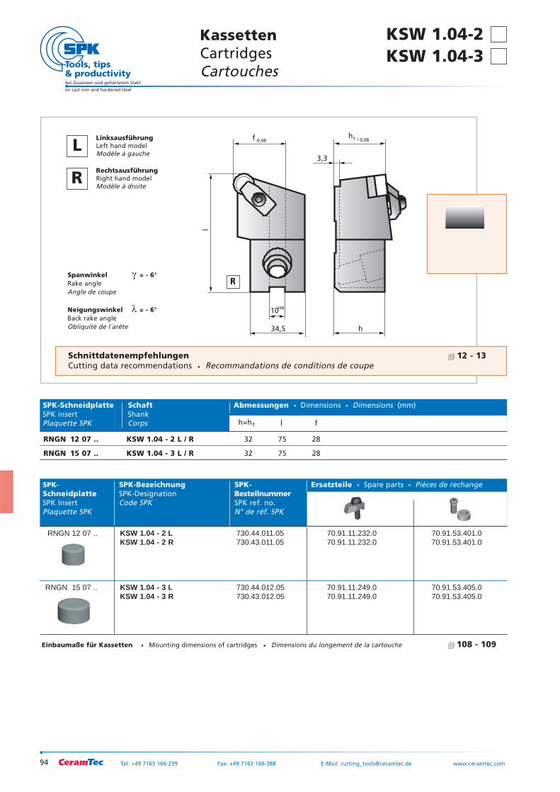
KSW 1.04-2 KSW 1.04-3
RNGN 12 07 .. KSW 1.04 - 2 L / R 32 75 28
RNGN 15 07 .. KSW 1.04 - 3 L / R 32 75 28
94
bei Gusseisen und gehärtetem Stahl
on cast iron and hardened steel
Tel: +49 7163 166-239 Fax: +49 7163 166-388 E-Mail: [email protected] www.ceramtec.com
34,5 h
10
3,3
f
H8
-0,08 0,08
l
h1
Spanwinkel γ = - 6°Rake angleAngle de coupe
Neigungswinkel λ = - 6°Back rake angleObliquité de l´arête
SPK- SPK-Bezeichnung SPK- Ersatzteile Spare parts Pièces de rechangeSchneidplatte SPK-Designation BestellnummerSPK Insert Code SPK SPK ref. no.Plaquette SPK N° de réf. SPK
RNGN 12 07 .. KSW 1.04 - 2 L 730.44.011.05 70.91.11.232.0 70.91.53.401.0KSW 1.04 - 2 R 730.43.011.05 70.91.11.232.0 70.91.53.401.0
RNGN 15 07 .. KSW 1.04 - 3 L 730.44.012.05 70.91.11.249.0 70.91.53.405.0KSW 1.04 - 3 R 730.43.012.05 70.91.11.249.0 70.91.53.405.0
SPK-Schneidplatte Schaft Abmessungen Dimensions Dimensions (mm)SPK insert ShankPlaquette SPK Corps h=h1 l f
KassettenCartridgesCartouches
R
LLinksausführungLeft hand modelModèle à gauche
RRechtsausführungRight hand modelModèle à droite
Schnittdatenempfehlungen 12 - 13Cutting data recommendations Recommandations de conditions de coupe
Einbaumaße für Kassetten Mounting dimensions of cartridges Dimensions du longement de la cartouche 108 - 109
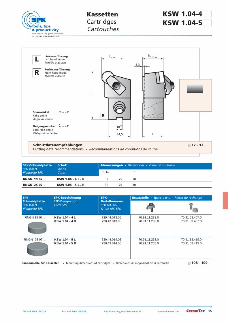
95
KSW 1.04-4 KSW 1.04-5
bei Gusseisen und gehärtetem Stahl
on cast iron and hardened steel
Tel: +49 7163 166-239 Fax: +49 7163 166-388 E-Mail: [email protected] www.ceramtec.com
KassettenCartridgesCartouches
34,5 h
10
3,3
f
H8
-0,08 0,08
l
h1
Spanwinkel γ = - 6°Rake angleAngle de coupe
Neigungswinkel λ = - 6°Back rake angleObliquité de l´arête
SPK- SPK-Bezeichnung SPK- Ersatzteile Spare parts Pièces de rechangeSchneidplatte SPK-Designation BestellnummerSPK Insert Code SPK SPK ref. no.Plaquette SPK N° de réf. SPK
RNGN 19 07 .. KSW 1.04 - 4 L 730.44.013.05 70.91.11.233.0 70.91.53.407.0KSW 1.04 - 4 R 730.43.013.05 70.91.11.233.0 70.91.53.407.0
RNGN 25 07 .. KSW 1.04 - 5 L 730.44.014.05 70.91.11.233.0 70.91.53.419.0KSW 1.04 - 5 R 730.43.014.05 70.91.11.233.0 70.91.53.419.0
SPK-Schneidplatte Schaft Abmessungen Dimensions Dimensions (mm)SPK insert ShankPlaquette SPK Corps h=h1 l f
RNGN 19 07 .. KSW 1.04 - 4 L / R 32 75 30
RNGN 25 07 .. KSW 1.04 - 5 L / R 32 75 30
R
LLinksausführungLeft hand modelModèle à gauche
RRechtsausführungRight hand modelModèle à droite
Schnittdatenempfehlungen 12 - 13Cutting data recommendations Recommandations de conditions de coupe
Einbaumaße für Kassetten Mounting dimensions of cartridges Dimensions du longement de la cartouche 108 - 109
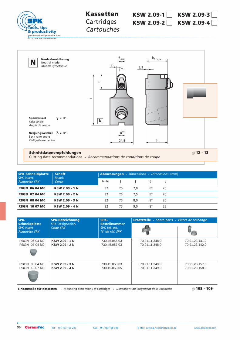
96
bei Gusseisen und gehärtetem Stahl
on cast iron and hardened steel
Tel: +49 7163 166-239 Fax: +49 7163 166-388 E-Mail: [email protected] www.ceramtec.com
h
3,3
0,08h1
24,5
8
f
�
H8
-0,08
l
t
Spanwinkel γ = 0°Rake angleAngle de coupe
Neigungswinkel λ = 0°Back rake angleObliquité de l´arête
SPK- SPK-Bezeichnung SPK- Ersatzteile Spare parts Pièces de rechangeSchneidplatte SPK-Designation BestellnummerSPK Insert Code SPK SPK ref. no.Plaquette SPK N° de réf. SPK
RBGN 06 04 M0 KSW 2.09 - 1 N 730.45.056.03 70.91.11.348.0 70.91.23.141.0RBGN 07 04 M0 KSW 2.09 - 2 N 730.45.057.03 70.91.11.348.0 70.91.23.142.0
RBGN 08 04 M0 KSW 2.09 - 3 N 730.45.058.03 70.91.11.349.0 70.91.23.157.0RBGN 10 07 M0 KSW 2.09 - 4 N 730.45.059.05 70.91.11.349.0 70.91.23.158.0
SPK-Schneidplatte Schaft Abmessungen Dimensions Dimensions (mm)SPK insert ShankPlaquette SPK Corps h=h1 l f δ t
RBGN 06 04 M0 KSW 2.09 - 1 N 32 75 7,0 8° 20
RBGN 07 04 M0 KSW 2.09 - 2 N 32 75 7,5 8° 20
RBGN 08 04 M0 KSW 2.09 - 3 N 32 75 8,0 8° 20
RBGN 10 07 M0 KSW 2.09 - 4 N 32 75 9,0 8° 25
Einbaumaße für Kassetten Mounting dimensions of cartridges Dimensions du longement de la cartouche 108 - 109
KSW 2.09-3KassettenCartridgesCartouches
N
NNeutralausführungNeutral modelModèle symétrique
KSW 2.09-4
Schnittdatenempfehlungen 12 - 13Cutting data recommendations Recommandations de conditions de coupe
KSW 2.09-1KSW 2.09-2
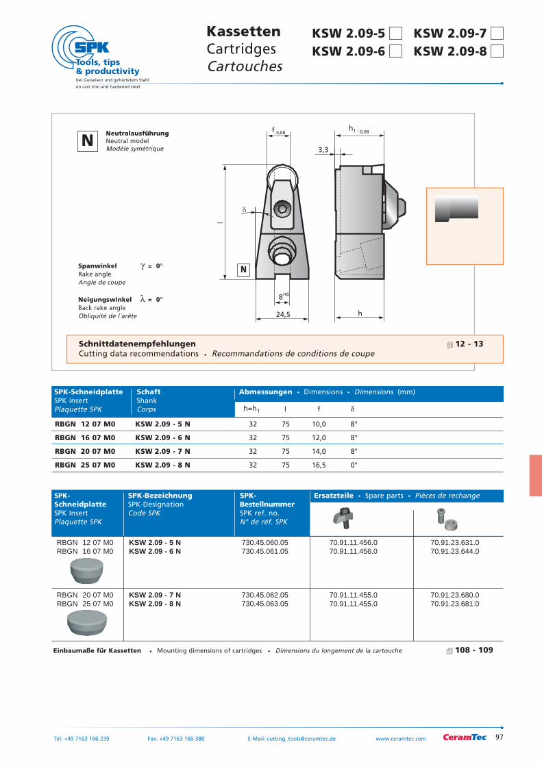
97
bei Gusseisen und gehärtetem Stahl
on cast iron and hardened steel
Tel: +49 7163 166-239 Fax: +49 7163 166-388 E-Mail: [email protected] www.ceramtec.com
KassettenCartridgesCartouches
h
3,3
0,08h1
24,5
8
f
H8
-0,08
l
�
Spanwinkel γ = 0°Rake angleAngle de coupe
Neigungswinkel λ = 0°Back rake angleObliquité de l´arête
SPK- SPK-Bezeichnung SPK- Ersatzteile Spare parts Pièces de rechangeSchneidplatte SPK-Designation BestellnummerSPK Insert Code SPK SPK ref. no.Plaquette SPK N° de réf. SPK
RBGN 12 07 M0 KSW 2.09 - 5 N 730.45.060.05 70.91.11.456.0 70.91.23.631.0RBGN 16 07 M0 KSW 2.09 - 6 N 730.45.061.05 70.91.11.456.0 70.91.23.644.0
RBGN 20 07 M0 KSW 2.09 - 7 N 730.45.062.05 70.91.11.455.0 70.91.23.680.0RBGN 25 07 M0 KSW 2.09 - 8 N 730.45.063.05 70.91.11.455.0 70.91.23.681.0
SPK-Schneidplatte Schaft Abmessungen Dimensions Dimensions (mm)SPK insert ShankPlaquette SPK Corps h=h1 l f δ
RBGN 12 07 M0 KSW 2.09 - 5 N 32 75 10,0 8°
RBGN 16 07 M0 KSW 2.09 - 6 N 32 75 12,0 8°
RBGN 20 07 M0 KSW 2.09 - 7 N 32 75 14,0 8°
RBGN 25 07 M0 KSW 2.09 - 8 N 32 75 16,5 0°
Einbaumaße für Kassetten Mounting dimensions of cartridges Dimensions du longement de la cartouche 108 - 109
N
Schnittdatenempfehlungen 12 - 13Cutting data recommendations Recommandations de conditions de coupe
KSW 2.09-7KSW 2.09-8
KSW 2.09-5KSW 2.09-6
NNeutralausführungNeutral modelModèle symétrique
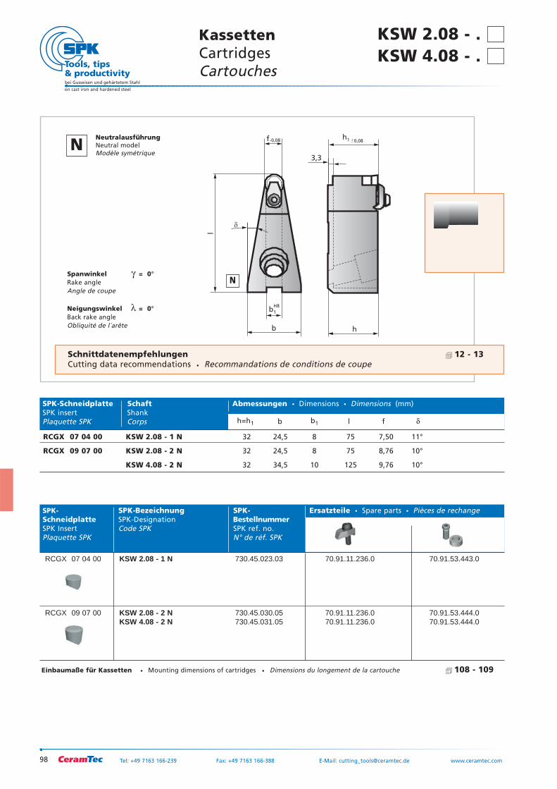
98
bei Gusseisen und gehärtetem Stahl
on cast iron and hardened steel
Tel: +49 7163 166-239 Fax: +49 7163 166-388 E-Mail: [email protected] www.ceramtec.com
b
f
H8
-0,08
l
h
3,3
0,08h1
b1
�
Spanwinkel γ = 0°Rake angleAngle de coupe
Neigungswinkel λ = 0°Back rake angleObliquité de l´arête
SPK- SPK-Bezeichnung SPK- Ersatzteile Spare parts Pièces de rechangeSchneidplatte SPK-Designation BestellnummerSPK Insert Code SPK SPK ref. no.Plaquette SPK N° de réf. SPK
RCGX 07 04 00 KSW 2.08 - 1 N 730.45.023.03 70.91.11.236.0 70.91.53.443.0
RCGX 09 07 00 KSW 2.08 - 2 N 730.45.030.05 70.91.11.236.0 70.91.53.444.0KSW 4.08 - 2 N 730.45.031.05 70.91.11.236.0 70.91.53.444.0
SPK-Schneidplatte Schaft Abmessungen Dimensions Dimensions (mm)SPK insert ShankPlaquette SPK Corps h=h1 b b1 l f δ
RCGX 07 04 00 KSW 2.08 - 1 N 32 24,5 8 75 7,50 11°
RCGX 09 07 00 KSW 2.08 - 2 N 32 24,5 8 75 8,76 10°
KSW 4.08 - 2 N 32 34,5 10 125 9,76 10°
Einbaumaße für Kassetten Mounting dimensions of cartridges Dimensions du longement de la cartouche 108 - 109
KassettenCartridgesCartouches
Schnittdatenempfehlungen 12 - 13Cutting data recommendations Recommandations de conditions de coupe
N
NNeutralausführungNeutral modelModèle symétrique
KSW 2.08 - . KSW 4.08 - .
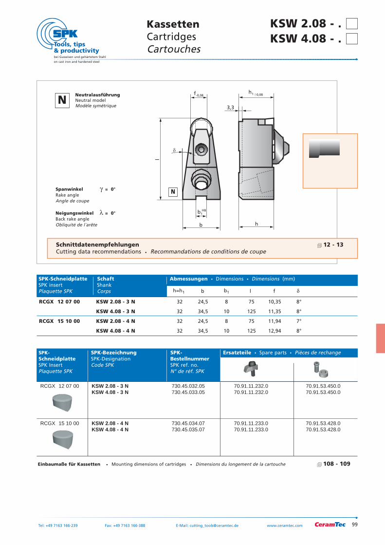
99
bei Gusseisen und gehärtetem Stahl
on cast iron and hardened steel
Tel: +49 7163 166-239 Fax: +49 7163 166-388 E-Mail: [email protected] www.ceramtec.com
RCGX 12 07 00 KSW 2.08 - 3 N 32 24,5 8 75 10,35 8°
KSW 4.08 - 3 N 32 34,5 10 125 11,35 8°
RCGX 15 10 00 KSW 2.08 - 4 N 32 24,5 8 75 11,94 7°
KSW 4.08 - 4 N 32 34,5 10 125 12,94 8°
KassettenCartridgesCartouches
h
3,3
0,08h1
b
f
H8
-0,08
l
b1
�
Spanwinkel γ = 0°Rake angleAngle de coupe
Neigungswinkel λ = 0°Back rake angleObliquité de l´arête
SPK- SPK-Bezeichnung SPK- Ersatzteile Spare parts Pièces de rechangeSchneidplatte SPK-Designation BestellnummerSPK Insert Code SPK SPK ref. no.Plaquette SPK N° de réf. SPK
RCGX 12 07 00 KSW 2.08 - 3 N 730.45.032.05 70.91.11.232.0 70.91.53.450.0KSW 4.08 - 3 N 730.45.033.05 70.91.11.232.0 70.91.53.450.0
RCGX 15 10 00 KSW 2.08 - 4 N 730.45.034.07 70.91.11.233.0 70.91.53.428.0KSW 4.08 - 4 N 730.45.035.07 70.91.11.233.0 70.91.53.428.0
SPK-Schneidplatte Schaft Abmessungen Dimensions Dimensions (mm)SPK insert ShankPlaquette SPK Corps h=h1 b b1 l f δ
Einbaumaße für Kassetten Mounting dimensions of cartridges Dimensions du longement de la cartouche 108 - 109
Schnittdatenempfehlungen 12 - 13Cutting data recommendations Recommandations de conditions de coupe
N
NNeutralausführungNeutral modelModèle symétrique
KSW 2.08 - . KSW 4.08 - .
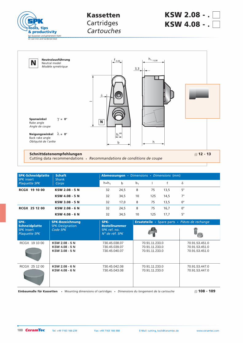
100
bei Gusseisen und gehärtetem Stahl
on cast iron and hardened steel
Tel: +49 7163 166-239 Fax: +49 7163 166-388 E-Mail: [email protected] www.ceramtec.com
h
3,3
0,08h1
b
f
H8
-0,08
l
b1
�
Spanwinkel γ = 0°Rake angleAngle de coupe
Neigungswinkel λ = 0°Back rake angleObliquité de l´arête
SPK- SPK-Bezeichnung SPK- Ersatzteile Spare parts Pièces de rechangeSchneidplatte SPK-Designation BestellnummerSPK Insert Code SPK SPK ref. no.Plaquette SPK N° de réf. SPK
RCGX 19 10 00 KSW 2.08 - 5 N 730.45.038.07 70.91.11.233.0 70.91.53.451.0KSW 4.08 - 5 N 730.45.039.07 70.91.11.233.0 70.91.53.451.0KSW 3.08 - 5 N 730.45.040.07 70.91.11.233.0 70.91.53.451.0
RCGX 25 12 00 KSW 2.08 - 6 N 730.45.042.08 70.91.11.233.0 70.91.53.447.0KSW 4.08 - 6 N 730.45.043.08 70.91.11.233.0 70.91.53.447.0
SPK-Schneidplatte Schaft Abmessungen Dimensions Dimensions (mm)SPK insert ShankPlaquette SPK Corps h=h1 b b1 l f δ
RCGX 19 10 00 KSW 2.08 - 5 N 32 24,5 8 75 13,5 5°
KSW 4.08 - 5 N 32 34,5 10 125 14,5 7°
KSW 3.08 - 5 N 32 17,0 8 75 13,5 0°
RCGX 25 12 00 KSW 2.08 - 6 N 32 24,5 8 75 16,7 0°
KSW 4.08 - 6 N 32 34,5 10 125 17,7 5°
Einbaumaße für Kassetten Mounting dimensions of cartridges Dimensions du longement de la cartouche 108 - 109
KSW 2.08 - . KassettenCartridgesCartouches
KSW 4.08 - .
Schnittdatenempfehlungen 12 - 13Cutting data recommendations Recommandations de conditions de coupe
N
NNeutralausführungNeutral modelModèle symétrique
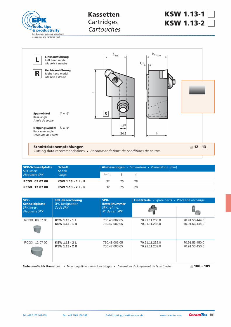
101
bei Gusseisen und gehärtetem Stahl
on cast iron and hardened steel
Tel: +49 7163 166-239 Fax: +49 7163 166-388 E-Mail: [email protected] www.ceramtec.com
KassettenCartridgesCartouches
KSW 1.13-1 KSW 1.13-2
34,5 h
10
3,3
f
H8
-0,08 0,08
l
h1
Spanwinkel γ = 0°Rake angleAngle de coupe
Neigungswinkel λ = 0°Back rake angleObliquité de l´arête
SPK- SPK-Bezeichnung SPK- Ersatzteile Spare parts Pièces de rechangeSchneidplatte SPK-Designation BestellnummerSPK Insert Code SPK SPK ref. no.Plaquette SPK N° de réf. SPK
RCGX 09 07 00 KSW 1.13 - 1 L 730.48.002.05 70.91.11.236.0 70.91.53.444.0KSW 1.13 - 1 R 730.47.002.05 70.91.11.236.0 70.91.53.444.0
RCGX 12 07 00 KSW 1.13 - 2 L 730.48.003.05 70.91.11.232.0 70.91.53.450.0KSW 1.13 - 2 R 730.47.003.05 70.91.11.232.0 70.91.53.450.0
SPK-Schneidplatte Schaft Abmessungen Dimensions Dimensions (mm)SPK insert ShankPlaquette SPK Corps h=h1 l f
RCGX 09 07 00 KSW 1.13 - 1 L / R 32 75 28
RCGX 12 07 00 KSW 1.13 - 2 L / R 32 75 28
R
LLinksausführungLeft hand modelModèle à gauche
RRechtsausführungRight hand modelModèle à droite
Schnittdatenempfehlungen 12 - 13Cutting data recommendations Recommandations de conditions de coupe
Einbaumaße für Kassetten Mounting dimensions of cartridges Dimensions du longement de la cartouche 108 - 109
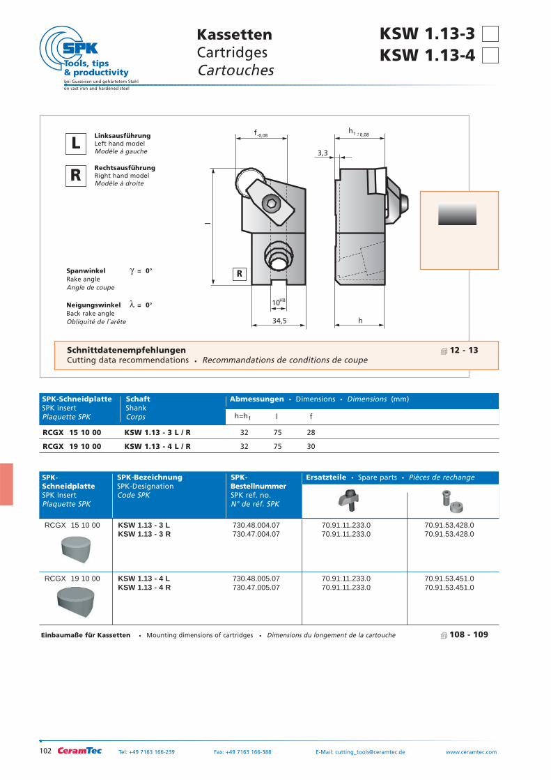
102
bei Gusseisen und gehärtetem Stahl
on cast iron and hardened steel
Tel: +49 7163 166-239 Fax: +49 7163 166-388 E-Mail: [email protected] www.ceramtec.com
34,5 h
10
3,3
f
H8
-0,08 0,08
l
h1
Spanwinkel γ = 0°Rake angleAngle de coupe
Neigungswinkel λ = 0°Back rake angleObliquité de l´arête
SPK- SPK-Bezeichnung SPK- Ersatzteile Spare parts Pièces de rechangeSchneidplatte SPK-Designation BestellnummerSPK Insert Code SPK SPK ref. no.Plaquette SPK N° de réf. SPK
RCGX 15 10 00 KSW 1.13 - 3 L 730.48.004.07 70.91.11.233.0 70.91.53.428.0KSW 1.13 - 3 R 730.47.004.07 70.91.11.233.0 70.91.53.428.0
RCGX 19 10 00 KSW 1.13 - 4 L 730.48.005.07 70.91.11.233.0 70.91.53.451.0KSW 1.13 - 4 R 730.47.005.07 70.91.11.233.0 70.91.53.451.0
SPK-Schneidplatte Schaft Abmessungen Dimensions Dimensions (mm)SPK insert ShankPlaquette SPK Corps h=h1 l f
RCGX 15 10 00 KSW 1.13 - 3 L / R 32 75 28
RCGX 19 10 00 KSW 1.13 - 4 L / R 32 75 30
KSW 1.13-3 KassettenCartridgesCartouches
R
LLinksausführungLeft hand modelModèle à gauche
RRechtsausführungRight hand modelModèle à droite
KSW 1.13-4
Schnittdatenempfehlungen 12 - 13Cutting data recommendations Recommandations de conditions de coupe
Einbaumaße für Kassetten Mounting dimensions of cartridges Dimensions du longement de la cartouche 108 - 109
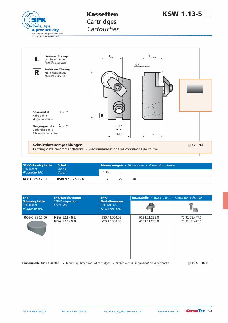
103
bei Gusseisen und gehärtetem Stahl
on cast iron and hardened steel
Tel: +49 7163 166-239 Fax: +49 7163 166-388 E-Mail: [email protected] www.ceramtec.com
KassettenCartridgesCartouches
KSW 1.13-5
34,5 h
10
3,3
f
H8
-0,08 0,08
l
h1
Spanwinkel γ = 0°Rake angleAngle de coupe
Neigungswinkel λ = 0°Back rake angleObliquité de l´arête
SPK- SPK-Bezeichnung SPK- Ersatzteile Spare parts Pièces de rechangeSchneidplatte SPK-Designation BestellnummerSPK Insert Code SPK SPK ref. no.Plaquette SPK N° de réf. SPK
RCGX 25 12 00 KSW 1.13 - 5 L 730.48.006.08 70.91.11.233.0 70.91.53.447.0KSW 1.13 - 5 R 730.47.006.08 70.91.11.233.0 70.91.53.447.0
SPK-Schneidplatte Schaft Abmessungen Dimensions Dimensions (mm)SPK insert ShankPlaquette SPK Corps h=h1 l f
RCGX 25 12 00 KSW 1.13 - 5 L / R 32 75 30
R
LLinksausführungLeft hand modelModèle à gauche
RRechtsausführungRight hand modelModèle à droite
Schnittdatenempfehlungen 12 - 13Cutting data recommendations Recommandations de conditions de coupe
Einbaumaße für Kassetten Mounting dimensions of cartridges Dimensions du longement de la cartouche 108 - 109
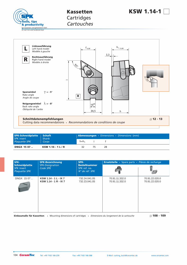
104
bei Gusseisen und gehärtetem Stahl
on cast iron and hardened steel
Tel: +49 7163 166-239 Fax: +49 7163 166-388 E-Mail: [email protected] www.ceramtec.com
h
3,3
0,08h1
34,5
10
f
H8
-0,08
l93°
Spanwinkel γ = - 5°Rake angleAngle de coupe
Neigungswinkel λ = - 8°Back rake angleObliquité de l´arête
SPK- SPK-Bezeichnung SPK- Ersatzteile Spare parts Pièces de rechangeSchneidplatte SPK-Designation BestellnummerSPK Insert Code SPK SPK ref. no.Plaquette SPK N° de réf. SPK
DNGX 15 07 .. KSW 1.14 - 1 L - IX 7 732.24.041.05 70.91.11.332.0 70.91.22.020.0KSW 1.14 - 1 R - IX 7 732.23.041.05 70.91.11.332.0 70.91.22.020.0
93°
SPK-Schneidplatte Schaft Abmessungen Dimensions Dimensions (mm)SPK insert ShankPlaquette SPK Corps h=h1 l f
DNGX 15 07 .. KSW 1.14 - 1 L / R 32 75 28
KSW 1.14-1 KassettenCartridgesCartouches
R
LLinksausführungLeft hand modelModèle à gauche
RRechtsausführungRight hand modelModèle à droite
Schnittdatenempfehlungen 12 - 13Cutting data recommendations Recommandations de conditions de coupe
Einbaumaße für Kassetten Mounting dimensions of cartridges Dimensions du longement de la cartouche 108 - 109
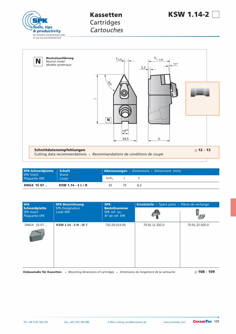
105
bei Gusseisen und gehärtetem Stahl
on cast iron and hardened steel
Tel: +49 7163 166-239 Fax: +49 7163 166-388 E-Mail: [email protected] www.ceramtec.com
KassettenCartridgesCartouches
KSW 1.14-2
h
3,3
0,08h1
34,5
10
f
H8
-0,08
l
63°
11°
SPK- SPK-Bezeichnung SPK- Ersatzteile Spare parts Pièces de rechangeSchneidplatte SPK-Designation BestellnummerSPK Insert Code SPK SPK ref. no.Plaquette SPK N° de réf. SPK
DNGX 15 07 .. KSW 1.14 - 2 N - IX 7 732.26.014.05 70.91.11.332.0 70.91.22.020.0
63°
SPK-Schneidplatte Schaft Abmessungen Dimensions Dimensions (mm)SPK insert ShankPlaquette SPK Corps h=h1 l f
DNGX 15 07 .. KSW 1.14 - 2 L / R 32 75 6,2
N
NNeutralausführungNeutral modelModèle symétrique
Schnittdatenempfehlungen 12 - 13Cutting data recommendations Recommandations de conditions de coupe
Einbaumaße für Kassetten Mounting dimensions of cartridges Dimensions du longement de la cartouche 108 - 109
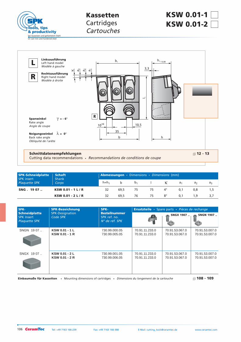
106
bei Gusseisen und gehärtetem Stahl
on cast iron and hardened steel
Tel: +49 7163 166-239 Fax: +49 7163 166-388 E-Mail: [email protected] www.ceramtec.com
h
35
b
3,3
10,5
a1
a2
a3�
0,08
10H8
h1b1
l 1
Spanwinkel γ = - 6°Rake angleAngle de coupe
Neigungswinkel λ = 0°Back rake angleObliquité de l´arête
SPK- SPK-Bezeichnung SPK- Ersatzteile Spare parts Pièces de rechangeSchneidplatte SPK-Designation BestellnummerSPK Insert Code SPK SPK ref. no.Plaquette SPK N° de réf. SPK
SNGN 19 07 .. KSW 0.01 - 1 L 730.99.000.05 70.91.11.233.0 70.91.53.067.0 70.91.53.007.0KSW 0.01 - 1 R 730.99.005.05 70.91.11.233.0 70.91.53.067.0 70.91.53.007.0
SNGX 19 07 .. KSW 0.01 - 2 L 730.99.001.05 70.91.11.233.0 70.91.53.067.0 70.91.53.007.0KSW 0.01 - 2 R 730.99.006.05 70.91.11.233.0 70.91.53.067.0 70.91.53.007.0
SPK-Schneidplatte Schaft Abmessungen Dimensions Dimensions (mm)SPK insert ShankPlaquette SPK Corps h=h1 b b1 l κ a1 a2 a3
SNG . 19 07 .. KSW 0.01 - 1 L / R 32 69,5 75 75 4° 0,1 0,8 1,5
KSW 0.01 - 2 L / R 32 69,5 76 75 8° 0,1 1,9 3,7
KSW 0.01-1 KassettenCartridgesCartouches
R
LLinksausführungLeft hand modelModèle à gauche
RRechtsausführungRight hand modelModèle à droite
KSW 0.01-2
Schnittdatenempfehlungen 12 - 13Cutting data recommendations Recommandations de conditions de coupe
Einbaumaße für Kassetten Mounting dimensions of cartridges Dimensions du longement de la cartouche 108 - 109
SNGX 1907 .. SNGN 1907 ..
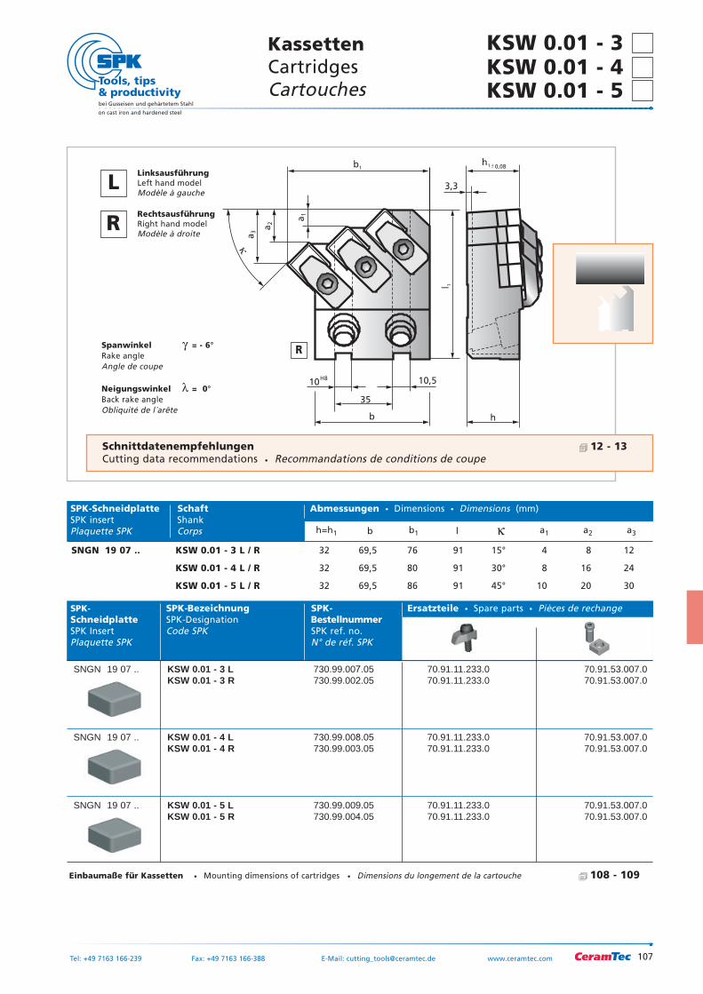
107
bei Gusseisen und gehärtetem Stahl
on cast iron and hardened steel
Tel: +49 7163 166-239 Fax: +49 7163 166-388 E-Mail: [email protected] www.ceramtec.com
KassettenCartridgesCartouches
KSW 0.01 - 3KSW 0.01 - 4 KSW 0.01 - 5
h
35
b
3,3
10,5
a1
a2
a3
�
0,08
10H8
h1b1
l 1
Spanwinkel γ = - 6°Rake angleAngle de coupe
Neigungswinkel λ = 0°Back rake angleObliquité de l´arête
SPK- SPK-Bezeichnung SPK- Ersatzteile Spare parts Pièces de rechangeSchneidplatte SPK-Designation BestellnummerSPK Insert Code SPK SPK ref. no.Plaquette SPK N° de réf. SPK
SNGN 19 07 .. KSW 0.01 - 3 L 730.99.007.05 70.91.11.233.0 70.91.53.007.0KSW 0.01 - 3 R 730.99.002.05 70.91.11.233.0 70.91.53.007.0
SNGN 19 07 .. KSW 0.01 - 4 L 730.99.008.05 70.91.11.233.0 70.91.53.007.0KSW 0.01 - 4 R 730.99.003.05 70.91.11.233.0 70.91.53.007.0
SNGN 19 07 .. KSW 0.01 - 5 L 730.99.009.05 70.91.11.233.0 70.91.53.007.0KSW 0.01 - 5 R 730.99.004.05 70.91.11.233.0 70.91.53.007.0
SPK-Schneidplatte Schaft Abmessungen Dimensions Dimensions (mm)SPK insert ShankPlaquette SPK Corps h=h1 b b1 l κ a1 a2 a3
SNGN 19 07 .. KSW 0.01 - 3 L / R 32 69,5 76 91 15° 4 8 12
KSW 0.01 - 4 L / R 32 69,5 80 91 30° 8 16 24
KSW 0.01 - 5 L / R 32 69,5 86 91 45° 10 20 30
Einbaumaße für Kassetten Mounting dimensions of cartridges Dimensions du longement de la cartouche 108 - 109
R
LLinksausführungLeft hand modelModèle à gauche
RRechtsausführungRight hand modelModèle à droite
Schnittdatenempfehlungen 12 - 13Cutting data recommendations Recommandations de conditions de coupe
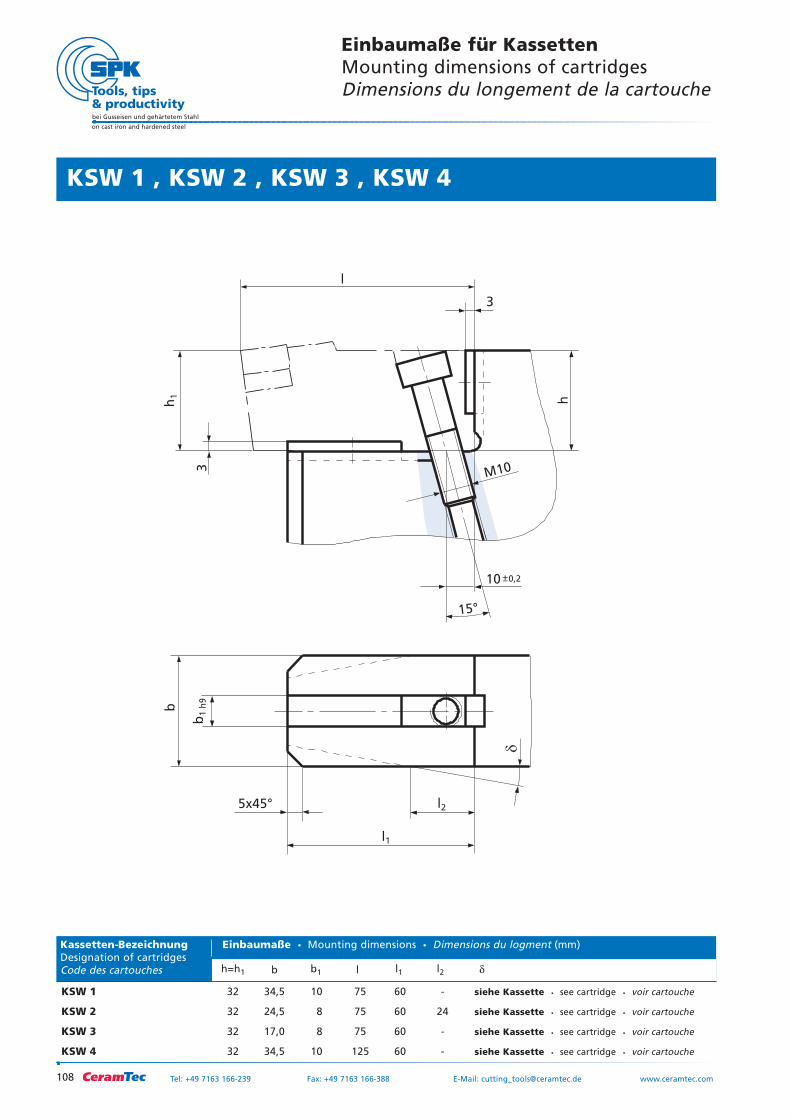
108
bei Gusseisen und gehärtetem Stahl
on cast iron and hardened steel
Tel: +49 7163 166-239 Fax: +49 7163 166-388 E-Mail: [email protected] www.ceramtec.com
KSW 1 32 34,5 10 75 60 - siehe Kassette see cartridge voir cartouche
KSW 2 32 24,5 8 75 60 24 siehe Kassette see cartridge voir cartouche
KSW 3 32 17,0 8 75 60 - siehe Kassette see cartridge voir cartouche
KSW 4 32 34,5 10 125 60 - siehe Kassette see cartridge voir cartouche
Einbaumaße für KassettenMounting dimensions of cartridgesDimensions du longement de la cartouche
3
3
l
5x45°
15°
M10
h1
b
b1
h9
l1
l2
h
10 0,2
KSW 1 , KSW 2 , KSW 3 , KSW 4
Kassetten-Bezeichnung Einbaumaße Mounting dimensions Dimensions du logment (mm)Designation of cartridgesCode des cartouches h=h1 b b1 l l1 l2 δ
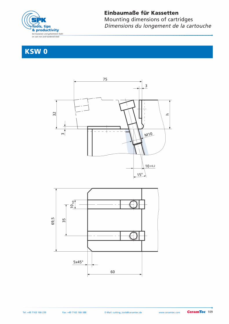
109
bei Gusseisen und gehärtetem Stahl
on cast iron and hardened steel
Tel: +49 7163 166-239 Fax: +49 7163 166-388 E-Mail: [email protected] www.ceramtec.com
3
3
75
5x45°
15°
M10
32
69,5
35
10
h9
60
h10 0,2
KSW 0
Einbaumaße für KassettenMounting dimensions of cartridgesDimensions du longement de la cartouche
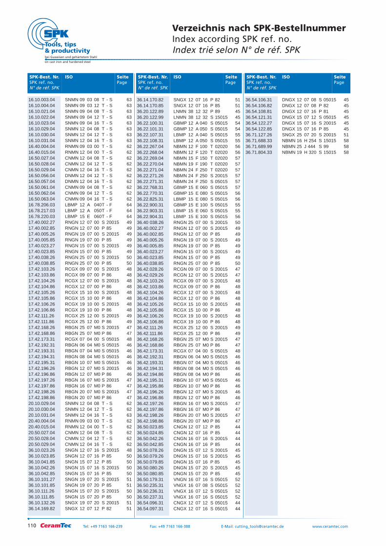
110
bei Gusseisen und gehärtetem Stahl
on cast iron and hardened steel
Tel: +49 7163 166-239 Fax: +49 7163 166-388 E-Mail: [email protected] www.ceramtec.com
SeitePage
ISOSPK-Best. Nr.SPK ref. no.N° de réf. SPK
SeitePage
ISOSPK-Best. Nr.SPK ref. no.N° de réf. SPK
SeitePage
ISOSPK-Best. Nr.SPK ref. no.N° de réf. SPK
Verzeichnis nach SPK-BestellnummerIndex according SPK ref. no.Index trié selon N° de réf. SPK
16.10.003.04 SNMN 09 03 08 T - S 6316.10.004.04 SNMN 09 03 12 T - S 6316.10.021.04 SNMN 09 04 08 T - S 6316.10.022.04 SNMN 09 04 12 T - S 6316.10.023.04 SNMN 09 04 16 T - S 6316.10.029.04 SNMN 12 04 08 T - S 6316.10.030.04 SNMN 12 04 12 T - S 6316.10.031.04 SNMN 12 04 16 T - S 6316.40.004.04 RNMN 09 03 00 T - S 6216.40.015.04 RNMN 12 04 00 T - S 6216.50.027.04 CNMN 12 04 08 T - S 6216.50.028.04 CNMN 12 04 12 T - S 6216.50.029.04 CNMN 12 04 16 T - S 6216.50.056.04 DNMN 12 04 12 T - S 6216.50.057.04 DNMN 12 04 16 T - S 6216.50.061.04 CNMN 09 04 08 T - S 6216.50.062.04 CNMN 09 04 12 T - S 6216.50.063.04 CNMN 09 04 16 T - S 6216.78.206.03 LBMP 12 A 040T - F 6416.78.217.03 LBMP 12 A 050T - F 6416.78.220.03 LBMP 15 E 060T - F 6417.40.002.27 RNGN 12 07 00 S 20015 4917.40.002.85 RNGN 12 07 00 P 85 4917.40.005.26 RNGN 19 07 00 S 20015 4917.40.005.85 RNGN 19 07 00 P 85 4917.40.023.27 RNGN 15 07 00 S 20015 4917.40.023.85 RNGN 15 07 00 P 85 4917.40.038.26 RNGN 25 07 00 S 20015 5017.40.038.85 RNGN 25 07 00 P 85 5017.42.103.26 RCGX 09 07 00 S 20015 4817.42.103.86 RCGX 09 07 00 P 86 4817.42.104.26 RCGX 12 07 00 S 20015 4817.42.104.86 RCGX 12 07 00 P 86 4817.42.105.26 RCGX 15 10 00 S 20015 4817.42.105.86 RCGX 15 10 00 P 86 4817.42.106.26 RCGX 19 10 00 S 20015 4817.42.106.86 RCGX 19 10 00 P 86 4817.42.111.26 RCGX 25 12 00 S 20015 4917.42.111.86 RCGX 25 12 00 P 86 4917.42.168.26 RBGN 25 07 M0 S 20015 4717.42.168.86 RBGN 25 07 M0 P 86 4717.42.173.31 RCGX 07 04 00 S 05015 4817.42.192.31 RBGN 06 04 M0 S 05015 4617.42.193.31 RBGN 07 04 M0 S 05015 4617.42.194.31 RBGN 08 04 M0 S 05015 4617.42.195.31 RBGN 10 07 M0 S 05015 4617.42.196.26 RBGN 12 07 M0 S 20015 4617.42.196.86 RBGN 12 07 M0 P 86 4617.42.197.26 RBGN 16 07 M0 S 20015 4717.42.197.86 RBGN 16 07 M0 P 86 4717.42.198.26 RBGN 20 07 M0 S 20015 4717.42.198.86 RBGN 20 07 M0 P 86 4720.10.029.04 SNMN 12 04 08 T - S 6220.10.030.04 SNMN 12 04 12 T - S 6220.10.031.04 SNMN 12 04 16 T - S 6320.40.004.04 RNMN 09 03 00 T - S 6220.40.015.04 RNMN 12 04 00 T - S 6220.50.027.04 CNMN 12 04 08 T - S 6220.50.028.04 CNMN 12 04 12 T - S 6220.50.029.04 CNMN 12 04 16 T - S 6236.10.023.26 SNGN 12 07 16 S 20015 4836.10.023.85 SNGN 12 07 16 P 85 5036.10.041.85 SNGN 15 07 12 P 85 5036.10.042.26 SNGN 15 07 16 S 20015 5036.10.042.85 SNGN 15 07 16 P 85 5036.10.101.27 SNGN 19 07 20 S 20015 5136.10.101.85 SNGN 19 07 20 P 85 5136.10.111.26 SNGN 15 07 20 S 20015 5036.10.111.85 SNGN 15 07 20 P 85 5036.10.132.26 SNGX 19 07 20 S 20015 5136.14.169.82 SNGX 12 07 12 P 82 51
36.54.106.31 DNGX 12 07 08 S 05015 4536.54.106.82 DNGX 12 07 08 P 82 4536.54.108.81 DNGX 12 07 16 P 81 4536.54.121.31 DNGX 15 07 12 S 05015 4536.54.122.27 DNGX 15 07 16 S 20015 4536.54.122.85 DNGX 15 07 16 P 85 4536.71.127.26 SNGX 25 07 20 S 20015 5136.71.688.33 NBMN 16 H 254 S 15015 5836.71.689.99 NBMN 25 J 444 S 99 5836.71.804.33 NBMN 19 H 320 S 15015 58
36.14.170.82 SNGX 12 07 16 P 82 5136.14.170.85 SNGX 12 07 16 P 85 5136.20.122.89 LNMN 38 12 32 P 89 4536.20.122.99 LNMN 38 12 32 S 15015 4536.22.100.31 GBMP 12 A 040 S 05015 5436.22.101.31 GBMP 12 A 050 S 05015 5436.22.107.31 LBMP 12 A 040 S 05015 5536.22.108.31 LBMP 12 A 050 S 05015 5536.22.267.04 NBMN 12 F 100 T 02020 5636.22.268.04 NBMN 12 F 120 T 02020 5636.22.269.04 NBMN 15 F 150 T 02020 5736.22.270.04 NBMN 19 F 190 T 02020 5736.22.271.04 NBMN 24 F 250 T 02020 5736.22.271.26 NBMN 24 F 250 S 20015 5736.22.271.31 NBMN 24 F 250 S 05015 5736.22.768.31 GBMP 15 E 060 S 05015 5736.22.770.31 GBMP 15 E 080 S 05015 5636.22.825.31 LBMP 15 E 080 S 05015 5636.22.900.31 GBMP 15 E 100 S 05015 5536.22.903.31 LBMP 15 E 060 S 05015 5536.22.904.31 LBMP 15 E 100 S 05015 5636.40 038.26 RNGN 25 07 00 S 20015 5036.40.002.27 RNGN 12 07 00 S 20015 4936.40.002.85 RNGN 12 07 00 P 85 4936.40.005.26 RNGN 19 07 00 S 20015 4936.40.005.85 RNGN 19 07 00 P 85 4936.40.023.27 RNGN 15 07 00 S 20015 4936.40.023.85 RNGN 15 07 00 P 85 4936.40.038.85 RNGN 25 07 00 P 85 5036.42.028.26 RCGN 09 07 00 S 20015 4736.42.029.26 RCGN 12 07 00 S 20015 4736.42.103.26 RCGX 09 07 00 S 20015 4836.42.103.86 RCGX 09 07 00 P 86 4836.42.104.26 RCGX 12 07 00 S 20015 4836.42.104.86 RCGX 12 07 00 P 86 4836.42.105.26 RCGX 15 10 00 S 20015 4836.42.105.86 RCGX 15 10 00 P 86 4836.42.106.26 RCGX 19 10 00 S 20015 4836.42.106.86 RCGX 19 10 00 P 86 4836.42.111.26 RCGX 25 12 00 S 20015 4936.42.111.86 RCGX 25 12 00 P 86 4936.42.168.26 RBGN 25 07 M0 S 20015 4736.42.168.86 RBGN 25 07 M0 P 86 4736.42.173.31 RCGX 07 04 00 S 05015 4836.42.192.31 RBGN 06 04 M0 S 05015 4636.42.193.31 RBGN 07 04 M0 S 05015 4636.42.194.31 RBGN 08 04 M0 S 05015 4636.42.194.86 RBGN 08 04 M0 P 86 4636.42.195.31 RBGN 10 07 M0 S 05015 4636.42.195.86 RBGN 10 07 M0 P 86 4636.42.196.26 RBGN 12 07 M0 S 20015 4636.42.196.86 RBGN 12 07 M0 P 86 4636.42.197.26 RBGN 16 07 M0 S 20015 4736.42.197.86 RBGN 16 07 M0 P 86 4736.42.198.26 RBGN 20 07 M0 S 20015 4736.42.198.86 RBGN 20 07 M0 P 86 4736.50.023.85 CNGN 12 07 12 P 85 4436.50.024.85 CNGN 12 07 16 P 85 4436.50.042.26 CNGN 16 07 16 S 20015 4436.50.042.85 CNGN 16 07 16 P 85 4436.50.078.26 DNGN 15 07 12 S 20015 4536.50.079.26 DNGN 15 07 16 S 20015 4536.50.079.85 DNGN 15 07 16 P 85 4536.50.080.26 DNGN 15 07 20 S 20015 4536.50.080.85 DNGN 15 07 20 P 85 4536.50.179.31 VNGN 16 07 16 S 05015 5236.50.235.31 VNGX 16 07 08 S 05015 5236.50.236.31 VNGX 16 07 12 S 05015 5236.50.237.31 VNGX 16 07 16 S 05015 5236.54.096.31 CNGX 12 07 12 S 05015 4436.54.097.31 CNGX 12 07 16 S 05015 44
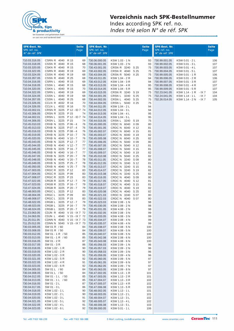
SeitePage
SPK-Best. Nr.SPK ref. no.N° de réf. SPK
SeitePage
SPK-Best. Nr.SPK ref. no.N° de réf. SPK
SeitePage
SPK-Best. Nr.SPK ref. no.N° de réf. SPK
Verzeichnis nach SPK-BestellnummerIndex according SPK ref. no.Index trié selon N° de réf. SPK
710.03.316.05 CSRN R 4040 R 15 69710.03.318.05 CSSN R 4040 R 15 68710.03.320.05 CSKN R 4040 R 15 70710.03.322.05 CSRN R 4040 R 19 69710.03.324.05 CSSN R 4040 R 19 68710.03.357.05 CSSN R 4040 R 25 68710.04.316.05 CSRN L 4040 R 15 69710.04.318.05 CSSN L 4040 R 15 68710.04.320.05 CSKN L 4040 R 15 70710.04.322.05 CSRN L 4040 R 19 69710.04.324.05 CSSN L 4040 R 19 68710.04.357.05 CSSN L 4040 R 25 68710.23.326.05 CCLN R 4032 R 16 70710.24.326.05 CCLN L 4032 R 16 70710.43.002.01 CRSN R 3225 P 12 - ID 7 74710.43.306.05 CRSN R 3225 P 15 74710.44.002.01 CRSN L 3225 P 12 - ID 7 74710.44.306.05 CRSN L 3225 P 15 74710.45.010.03 CRXB N 3225 P 06 - 4 76710.45.013.03 CRXB N 3225 P 07 - 4 76710.45.016.03 CRXB N 3225 P 08 - 4 76710.45.019.05 CRXB N 3225 P 10 - 7 76710.45.020.05 CRXB N 4040 V 10 - 7 76710.45.043.05 CRXB N 3225 P 12 - 7 77710.45.044.05 CRXB N 4040 V 12 - 7 77710.45.045.05 CRXB N 3225 P 16 - 7 77710.45.046.05 CRXB N 4040 V 16 - 7 77710.45.047.05 CRXB N 3225 P 20 - 7 78710.45.048.05 CRXB N 4040 V 20 - 7 78710.45.049.05 CRXB N 3225 P 25 - 7 78710.45.050.05 CRXB N 4040 V 25 - 7 78710.47.003.05 CRGC R 3225 P 12 83710.47.004.05 CRGC R 3225 P 09 83710.47.008.07 CRGC R 3225 P 15 83710.47.022.05 CRGB R 3225 P 12 - 7 79710.47.023.05 CRGB R 3225 P 16 - 7 79710.47.024.05 CRGB R 3225 P 20 - 7 79710.48.003.05 CRGC L 3225 P 12 83710.48.004.05 CRGC L 3225 P 09 83710.48.008.07 CRGC L 3225 P 15 83710.48.022.05 CRGB L 3225 P 12 - 7 79710.48.023.05 CRGB L 3225 P 16 - 7 79710.48.024.05 CRGB L 3225 P 20 - 7 79711.23.063.05 CDJN R 4040 V 15 - IX 7 72711.24.063.05 CDJN L 4040 V 15 - IX 7 72711.25.011.05 CDNN N 4040 V 15 - IX 7 73711.25.012.05 CDNN N 5040 V 15 - IX 7 73730.03.005.05 SW 01 R / 60 84730.03.008.05 SW 01 R / 50 84730.03.012.05 SW 01 - 1 R / 50 85730.03.013.05 SW 01 - 1 R / 60 85730.03.016.05 SW 01 - 2 R 87730.03.017.05 SW 01 - 3 R 86730.03.018.05 KSW 1.02 - 1 R 90730.03.019.05 KSW 1.02 - 2 R 90730.03.020.05 KSW 1.02 - 3 R 91730.03.021.05 KSW 1.02 - 5 R 92730.03.022.05 KSW 1.02 - 4 R 91730.03.023.05 KSW 1.02 - 6 R 92730.04.005.05 SW 01 L / 60 84730.04.008.05 SW 01 L / 50 84730.04.012.05 SW 01 - 1 L / 50 85730.04.013.05 SW 01 - 1 L / 60 85730.04.016.05 SW 01 - 2 L 87730.04.017.05 SW 01 - 3 L 86730.04.018.05 KSW 1.02 - 1 L 90730.04.019.05 KSW 1.02 - 2 L 90730.04.020.05 KSW 1.02 - 3 L 91730.04.021.05 KSW 1.02 - 5 L 92730.04.022.05 KSW 1.02 - 4 L 91730.04.023.05 KSW 1.02 - 6 L 92
730.99.001.05 KSW 0.01 - 2 L 106730.99.002.05 KSW 0.01 - 3 L 107730.99.003.05 KSW 0.01 - 4 L 107730.99.004.05 KSW 0.01 - 5 L 107730.99.005.05 KSW 0.01 - 1 R 106730.99.006.05 KSW 0.01 - 2 R 106730.99.007.05 KSW 0.01 - 3 R 107730.99.008.05 KSW 0.01 - 4 R 107730.99.009.05 KSW 0.01 - 5 R 107732.23.041.05 KSW 1.14 - 1 R - IX 7 104732.24.041.05 KSW 1.14 - 1 L - IX 7 104732.26.014.05 KSW 1.14 - 2 N - IX 7 105
730.06.000.05 KSW 1.03 - 1 N 93730.06.001.05 KSW 1.03 - 2 N 93730.43.001.05 CRSN R 3240 S 25 75730.43.002.05 CRSN R 4040 S 25 75730.43.004.05 CRSN R 5040 X 25 75730.43.011.05 KSW 1.04 - 2 R 94730.43.012.05 KSW 1.04 - 3 R 94730.43.013.05 KSW 1.04 - 4 R 95730.43.014.05 KSW 1.04 - 5 R 95730.43.015.05 CRSN R 3240 S 19 75730.44.001.05 CRSN L 3240 S 25 75730.44.002.05 CRSN L 4040 S 25 75730.44.004.05 CRSN L 5040 X 25 75730.44.011.05 KSW 1.04 - 2 L 94730.44.012.05 KSW 1.04 - 3 L 94730.44.013.05 KSW 1.04 - 4 L 95730.44.014.05 KSW 1.04 - 5 L 95730.44.015.05 CRSN L 3240 S 19 75730.45.000.05 CRDC N 6040 X 09 80730.45.001.05 CRDC N 6040 X 12 81730.45.002.07 CRDC N 6040 X 15 81730.45.003.07 CRDC N 6040 X 19 82730.45.005.08 CRDC N 6040 X 25 82730.45.006.05 CRDC N 5040 X 09 80730.45.007.05 CRDC N 5040 X 12 81730.45.008.07 CRDC N 5040 X 15 81730.45.009.07 CRDC N 5040 X 19 82730.45.010.08 CRDC N 5040 X 25 82730.45.011.05 CRDC N 3240 S 09 80730.45.012.05 CRDC N 3240 S 12 81730.45.013.07 CRDC N 3240 S 15 81730.45.014.07 CRDC N 3240 S 19 82730.45.015.08 CRDC N 3240 S 25 82730.45.016.05 CRDC N 4040 S 09 80730.45.017.05 CRDC N 4040 S 12 81730.45.018.07 CRDC N 4040 S 15 81730.45.019.07 CRDC N 4040 S 19 82730.45.020.08 CRDC N 4040 S 25 82730.45.021.03 CRDC N 3240 S 07 80730.45.022.03 CRDC N 4040 S 07 80730.45.023.03 KSW 2.08 - 1 N 98730.45.030.05 KSW 2.08 - 2 N 98730.45.031.05 KSW 4.08 - 2 N 98730.45.032.05 KSW 2.08 - 3 N 99730.45.033.05 KSW 4.08 - 3 N 99730.45.034.07 KSW 2.08 - 4 N 99730.45.035.07 KSW 4.08 - 4 N 99730.45.038.07 KSW 2.08 - 5 N 100730.45.039.07 KSW 4.08 - 5 N 100730.45.040.07 KSW 3.08 - 5 N 100730.45.042.08 KSW 2.08 - 6 N 100730.45.043.08 KSW 4.08 - 6 N 100730.45.056.03 KSW 2.09 - 1 N 96730.45.057.03 KSW 2.09 - 2 N 96730.45.058.03 KSW 2.09 - 3 N 96730.45.059.05 KSW 2.09 - 4 N 96730.45.060.05 KSW 2.09 - 5 N 97730.45.061.05 KSW 2.09 - 6 N 97730.45.062.05 KSW 2.09 - 7 N 97730.45.063.05 KSW 2.09 - 8 N 97730.47.002.05 KSW 1.13 - 1 R 101730.47.003.05 KSW 1.13 - 2 R 101730.47.004.07 KSW 1.13 - 3 R 102730.47.005.07 KSW 1.13 - 4 R 102730.47.006.08 KSW 1.13 - 5 R 103730.48.002.05 KSW 1.13 - 1 L 101730.48.003.05 KSW 1.13 - 2 L 101730.48.004.07 KSW 1.13 - 3 L 102730.48.005.07 KSW 1.13 - 4 L 102730.48.006.08 KSW 1.13 - 5 L 103730.99.000.05 KSW 0.01 - 1 L 106
111
bei Gusseisen und gehärtetem Stahl
on cast iron and hardened steel
Tel: +49 7163 166-239 Fax: +49 7163 166-388 E-Mail: [email protected] www.ceramtec.com
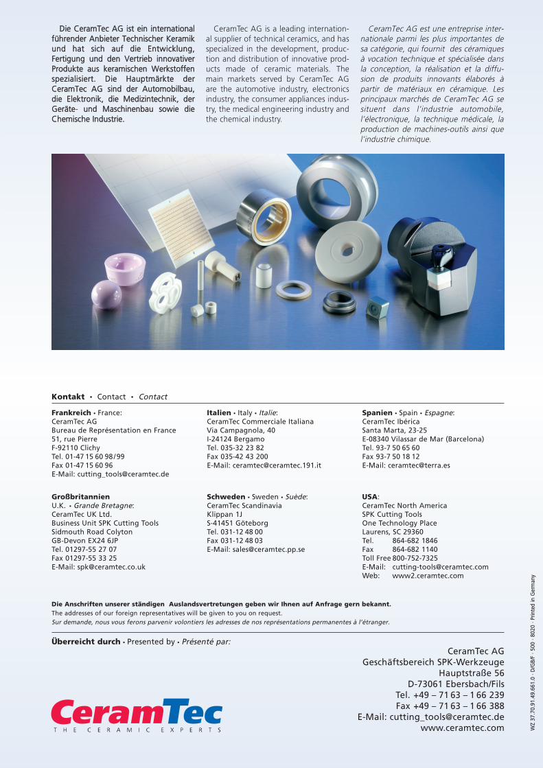
bei Gusseisen und gehärtetem Stahl
on cast iron and hardened steel
WZ
337.7
0.91
.49.
661.
0 ··
DD/G
B/F
·· 550
0 ··
88020
·· PP
rinte
d iin
GGer
man
y
CeramTec AGGeschäftsbereich SPK-Werkzeuge
Hauptstraße 56D-73061 Ebersbach/Fils
Tel. +49 – 71 63 – 1 66 239Fax +49 – 71 63 – 1 66 388
E-Mail: [email protected]
Frankreich France:CeramTec AGBureau de Représentation en France51, rue PierreF-92110 ClichyTel. 01-47 15 60 98/99Fax 01-47 15 60 96E-Mail: [email protected]
GroßbritannienU.K. Grande Bretagne:CeramTec UK Ltd.Business Unit SPK Cutting ToolsSidmouth Road ColytonGB-Devon EX24 6JPTel. 01297-55 27 07Fax 01297-55 33 25E-Mail: [email protected]
Italien Italy Italie:CeramTec Commerciale ItalianaVia Campagnola, 40I-24124 BergamoTel. 035-32 23 82Fax 035-42 43 200E-Mail: [email protected]
Schweden Sweden Suède:CeramTec ScandinaviaKlippan 1JS-41451 GöteborgTel. 031-12 48 00Fax 031-12 48 03E-Mail: [email protected]
Spanien Spain Espagne:CeramTec IbéricaSanta Marta, 23-25E-08340 Vilassar de Mar (Barcelona)Tel. 93-7 50 65 60Fax 93-7 50 18 12E-Mail: [email protected]
USA:CeramTec North AmericaSPK Cutting ToolsOne Technology PlaceLaurens, SC 29360Tel. 864-682 1846Fax 864-682 1140Toll Free 800-752-7325E-Mail: [email protected]: www2.ceramtec.com
Kontakt Contact Contact
Überreicht durch Presented by Présenté par:
Die Anschriften unserer ständigen Auslandsvertretungen geben wir Ihnen auf Anfrage gern bekannt.The addresses of our foreign representatives will be given to you on request.Sur demande, nous vous ferons parvenir volontiers les adresses de nos représentations permanentes à l’étranger.
Die CCeramTec AAG iist eein iinternationalführender AAnbieter TTechnischer KKeramikund hhat ssich aauf ddie EEntwicklung,Fertigung uund dden VVertrieb iinnovativer Produkte aaus kkeramischen WWerkstoffenspezialisiert. DDie HHauptmärkte dder CeramTec AAG ssind dder AAutomobilbau,die EElektronik, ddie MMedizintechnik, dderGeräte- uund MMaschinenbau ssowie ddieChemische IIndustrie.
CeramTec AG is a leading internation-al supplier of technical ceramics, and hasspecialized in the development, produc-tion and distribution of innovative prod-ucts made of ceramic materials. Themain markets served by CeramTec AGare the automotive industry, electronicsindustry, the consumer appliances indus-try, the medical engineering industry andthe chemical industry.
CeramTec AG est une entreprise inter-nationale parmi les plus importantes desa catégorie, qui fournit des céramiquesà vocation technique et spécialisée dansla conception, la réalisation et la diffu-sion de produits innovants élaborés àpartir de matériaux en céramique. Lesprincipaux marchés de CeramTec AG sesituent dans l’industrie automobile,l’électronique, la technique médicale, laproduction de machines-outils ainsi quel’industrie chimique.