Embed Size (px)
Citation preview
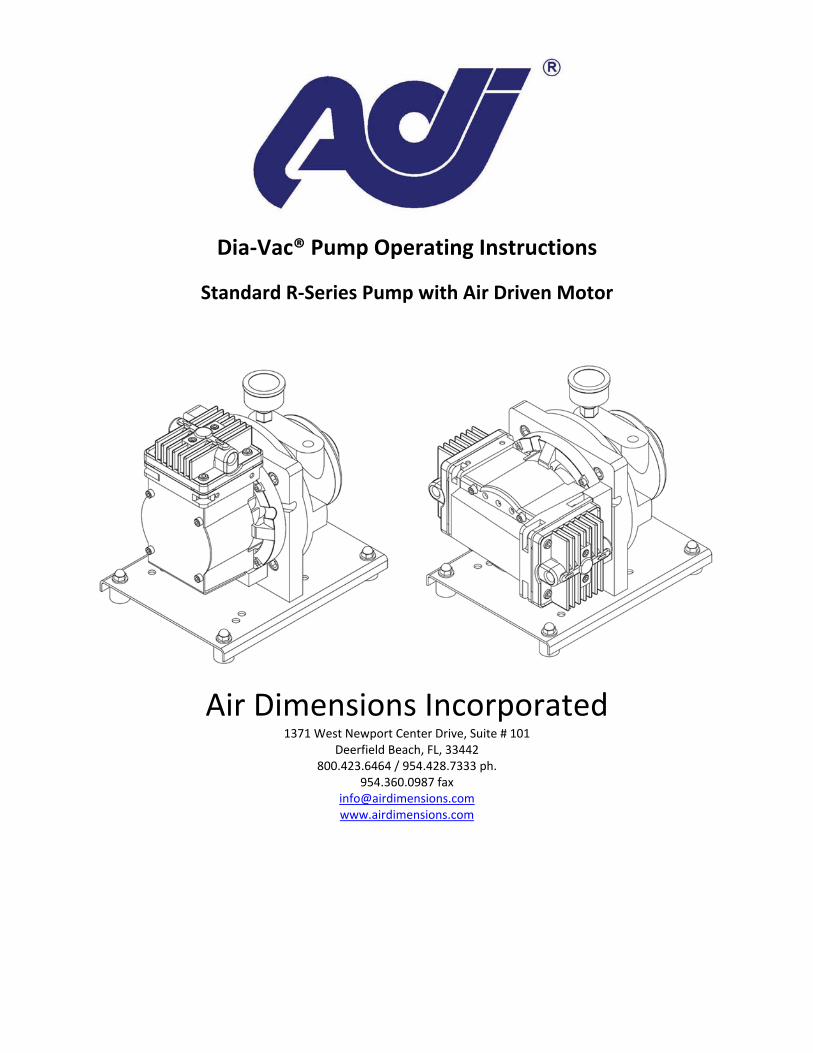
Dia‐Vac® Pump Operating Instructions
Standard R‐Series Pump with Air Driven Motor
Air Dimensions Incorporated 1371 West Newport Center Drive, Suite # 101
Deerfield Beach, FL, 33442 800.423.6464 / 954.428.7333 ph.
954.360.0987 fax [email protected] www.airdimensions.com

2
General Operating Conditions
The R‐Series Dia‐Vac® air driven pump is suitable for use in Class I Div I, and Zone 1 group IIB locations. Dia‐Vac® Pumps are intended for use with gases only, do not use this product for liquids. For applications where liquid may be present in the gas stream, mount the pump so that the discharge port faces toward the ground. Mounting the pump at the highest point in the system will prevent liquid from collecting in the pump head. An elevated or steam trace heated head pump may be required to maintain the gas temperature through the head. Ambient temperature of this pump should not exceed 150°F. The pump must have adequate ventilation and/or cooling to run properly.
Safety
Before running the pump, ensure that it is properly rated for the environment in which it is located. The R‐Series Dia‐Vac® air driven pump is suitable for use in Class I Div I, and Zone 1 group IIB locations. All system components connected to the Dia‐Vac® Pump must be capable of handling the maximum pressure of the pump. All proper precautions for the controlled vapor must be observed, and followed. Proper wetted materials for handling corrosive, hot, and/or reactive gases must be used. Disassembly of the pump or motor beyond what is detailed in the servicing section below may result in the loss of the pump’s hazardous area certification and is highly discouraged.
Operation
This pump should not be installed outdoors without additional protection i.e. a protective container. This pump requires lubrication added to the air stream driving the motor. One drop of lubricant for every 50 CFM of flow should be added upstream of motor. If the gas stream has a high level of particulate matter, a filter should be installed before the pump. If the gas stream has a high level of liquid matter, a membrane separator should be installed before the pump. This should be used in conjunction with best practices for pump installation including mounting the pump head so that the discharge port faces toward the ground. Keep in mind that the pump head can be rotated in any direction on the housing. The gas will always flow in the direction of the arrows on top of the head. This pump can be mounted in any position. If the housing needs to be rotated for mounting purposes, that can be done at the ADI facility. Do not start the pump against pressure or vacuum. For applications that must start under pressure or vacuum, contact ADI and a suitable motor will be selected.
Once the pump/motor assembly is installed and fully plumbed, a tachometer should then be used to measure the speed of the motor. Starting with zero pressure on the inlet of the Air Motor,
3
apply pressure by adjusting the regulator until the tachometer reads between 1700‐2000 RPM. Set the regulator. If a tachometer is not available, the Air Driven Std. Dia‐Vac generally requires approximately 40‐50 PSIG and 26‐32 SCFM at the Air motor inlet to function properly. Do not exceed 90 PSIG or 3000 RPM on the motor. NOTE: The speed (RPM) can be adjusted if desired to achieve better pump performance. However, do not exceed the maximum recommend speed for the Std. air motor of 3000 RPM. For high pressure applications, outlet pressures above 15 psig, please consult an ADI representative for proper motor sizing. The pump is designed for atmospheric pressure or vacuum on the inlet. For applications with inlet pressure greater than 0 psig; contact ADI and a suitable pump will be selected. The diaphragm, valve discs, sealing washer, and gasket are the only consumable parts of the pump. The degree of usage and condition of operating temperatures or pressure will determine the rate of replacement of part or parts. For heavy loads (25‐75 PSI) and constant operation the diaphragm should be inspected at least every six months. For lighter loads (0‐15 PSI or up to maximum vacuum) or pumps with reduced eccentric the diaphragm may operate successfully for a year or more. The corrosive content of the gas media being pumped can affect the recommended inspection and replacement cycle of the diaphragm.

4
NOTE: Check each separately, one or the other port must be open during this test. Use 0‐100 PSI pressure gauge and 0‐30 inch Hg vacuum gauge, (or mercury manometer.)
Troubleshooting
This section lists common problems that occur, possible causes and the most common fixes. If the problem persists, the pump may require inspection at the ADI facility. To have your pump inspected and repaired at the ADI facility please follow the instructions on the ADI website located at http://www.airdimensions.com/service/rma/.
Eccentric
R27x
R25x
R22x
R20x
R18x
R15x
R12x
R10x
R08x
R06x
12
11
8
19
17
14
11
27
25
26
22
20
17
7
15
13
7
4
24
23.5
23
21.5
17
13
8
46
36
27
MinimumLPM
MinimumIn Hg
60
52
Minimum Performance Requirements
Max Press Open Flow Ult Vac
MinimumPSIG
Standard Product 60Hz

5
Low or zero flow
Connection or sample line blocked Remove blockage
Liquid or foreign debris has collected in the head Clean out the head, see section “Servicing” Place pump outlet facing downward
Diaphragms, valves, or gasket are worn See section “Servicing”
Pump is rattling or knocking
Connecting rod bolt or diaphragm plate screw are under torqued See Appendix A for torquing specifications
Connecting rod cap is too close to one side of housing Using a screw driver lightly pry the cap away from the side of the housing
and center. A centering tool is available for purchase at ADI.
Servicing
Listed below are the two predominant types of maintenance typical for Dia‐Vac® Pumps, the servicing of the consumable parts (diaphragm, valve discs, gasket, and Teflon® washer), and the servicing of the connecting rod. For video instructions on servicing the head and diaphragm visit http://www.airdimensions.com/service/videos/.
Disassembly of Head Section and Diaphragm
Remove head assembly by unscrewing the four head bolts. A flat‐bladed screw driver may be needed to gently pry the head free of the service diaphragm. **If the heads have Teflon® coating use caution not to scratch the surface. The valve body can then be removed by unscrewing the two smaller screws (also accessible on the top of the head section). This part may be freed by gently tapping on these two screws after they have been loosened about three or four turns. When the valve body is removed, check all internal surfaces for any accumulation of dirt. The two valve discs can be wiped clean and replaced as long as they appear unaffected by usage. The valve gasket can be easily removed and should be inspected. As a matter of good practice, the valve discs and valve gasket should be replaced during any routine maintenance check of the head section. A once a year routine procedure is recommended. The diaphragm is secured by the single screw in its center. Remove this screw with an Allen wrench. The diaphragm and its clamping plate should be easily lifted off. Some slight adherence to the metal may occur if the diaphragm has been in use for a long period. To reattach diaphragm, first insert the diaphragm plate screw through the Teflon® washer, then through the diaphragm plate, then finally through the diaphragm. Next apply a drop of a medium strength thread locker (such as Loctite®242) to the screw. Tighten the diaphragm plate screw into the connecting rod bolt. It is important that when reassembling your pump you follow the torquing specifications listed below. NOTE: When replacing the diaphragm, be sure the four projecting studs of the base casting are properly located in the four outer slots provided in the diaphragm before the part is clamped in place. Be sure the diaphragm plate is firmly fastened with its center screw. Failure to use a thread locker may result in the diaphragm plate screw backing out, resulting in damage to the pump.

6
If a problem occurs, the pump may require inspection at the ADI facility. To have your pump inspected and repaired at the ADI facility please follow the instructions on the ADI website located at http://www.airdimensions.com/service/rma/.
Disassembly of the Connecting Rod
Remove head assembly and service diaphragm as described in the section above. Using a hex socket wrench, remove the hex head bolt on the connecting rod top surface. This will release the connecting rod cap which may then be lifted off. The previous two steps should be repeated for every head of the pump. Remove the front plate (single head)/second stage housing (double and quad head) from the primary stage housing by removing the four retaining screws using an Allen wrench. The connecting rod assembly on single head units, including the counterweight, is held in place by the counterweight screw. This can be loosened by an Allen wrench. The connecting rod assembly may then be slid off the motor shaft. On the dual head units the assembly is held in place by the set screw. This can be loosened by an Allen wrench and the assembly may then be slid off the motor shaft. Due to the complicated nature of the quad head pump it is highly recommended that the pump is shipped back to the ADI facility for any connecting rod maintenance.
Replacement of the Connecting Rod
Replace the connecting rod assembly on the motor shaft, taking care to align set screw or counterweight screw as squarely as possible on the flat of the motor shaft. Replace the connecting rod cap and connecting rod bolt. **It is important to follow the torqueing specifications in Appendix A.
Spare Parts
Kit # Description
11005 KIT, REPAIR ‐ TEFLON®/EPDM
11007 KIT, REPAIR ‐ VITON®
11009 KIT, REPAIR ‐ EPDM
11011 KIT, REPAIR ‐ ALL TEFLON®
For a complete list of spare parts please follow the following links: Single Head Pump: http://airdimensionscom.c.presscdn.com/wp‐content/uploads/2014/11/Rxx1‐xx‐DX0_Part2.pdf

7
Double Head Pump: http://airdimensionscom.c.presscdn.com/wp‐content/uploads/2014/11/Rxx2‐xx‐DX0_Part2.pdf Quad Head Pump: http://airdimensionscom.c.presscdn.com/wp‐content/uploads/2014/11/Rxx4‐xx‐DX0_Part2.pdf
Warranty
All Air Dimensions Incorporated Dia‐Vac® Pumps are under warranty for 12 months from the ship date. The warranty does not cover consumable parts (diaphragm, flapper valve gasket, and Teflon® washer). For complete terms and conditions please see Appendix D.

TITLE
MODEL #
AIR DIMENSIONS INC.
DEERFIELD BEACH, FL. USA 33442
WWW.AIRDIMENSIONS.COM
DWG NO
DATE
APPROVED BY
R-Series Torque Chart
1
1
2
2
3
3
4
4
A A
B B
C C
D D
Appendix A - R-Series Torque Chart
110 inch pounds
70 inch pounds
150 inch pounds
110 inch pounds
Apply Loctite
Apply Loctite
Apply Loctite
70 inch pounds

8
Appendix B‐ Maximum Gas Temperature for ADI Diaphragms
Diaphragm Material Max Temperature Comments
Teflon Coated EPDM 250 °F (121 °C) Not available in J‐Series
EPDM 250 °F (121 °C) Not available in J‐Series, H‐Series
Viton 400 °F (205 °C) Not available in J‐Series, H‐Series
Teflon/Viton 400 °F (205 °C) J‐Series Only
All Teflon 400 °F (205 °C)

AIR SOURCE
Pressure Regulator
Filter Emergency Shutoff Valve3/8" ID minimum ball valve
Appendix C - Air Motor Installation Guide
Tube 3/8" (10mm) ID minimum
Pressure Gauge12.0 [30 cm]
12.0 [30 cm]See note 1.
See note 1.
PCO 032 Rev 1
Note:1. The tube length from the regulator to the air motor should be no more than 2 feet (61 cm) long.
Inline Motor Lubricator
9
Appendix D‐ TERMS AND CONDITIONS OF ACKNOWLEDGMENT OF ORDER 1. EXCLUSIVE REMEDY. Seller will replace or, at its option, repair any products or parts thereof which are found defective by Seller in material or workmanship within one year from date of shipment, provided the product has been properly installed, maintained and operated. Seller's obligation with respect to such products will be exclusively limited to repair or replacement F.O.B. Deerfield Beach, Florida, U.S.A., and in no event shall Seller be liable for consequential or special damages, or for transportation, installation, adjustment, or other expenses which may arise in connection with such products. NO EXPRESS WARRANTIES AND NO IMPLIED WARRANTIES WHETHER OF MERCHANTABILITY OF FITNESS FOR ANY PARTICULAR USE, OR OTHERWISE (EXCEPT AS TO TITLE), SHALL APPLY TO PRODUCTS SOLD BY US, AND NO WAIVER, ALTERATION, OR MODIFICATION OF THE FOREGOING CONDITIONS SHALL BE VALID UNLESS MADE IN WRITING AND SIGNED BY AN OFFICER OF SELLER. 2. METHOD OF SHIPMENT. This apparatus will be shipped “knocked down” to the extent we consider necessary for proper shipment with small parts. 3. SHIPMENT. All goods are shipped F.O.B. shipping point which shall be Deerfield Beach, FL unless otherwise specified. Risk of loss of damage to goods in transit shall fall upon Buyer. 4. TERMS. Subject to any prior written agreement to the contrary, and to approval of credit, payment for products shall be made Net 30 days from date of invoice. If in Seller’s opinion the financial condition of Buyer does not justify continuance of production or shipment on the terms of payment specified, Seller may, at its option, require full or partial payment in advance. Seller reserves the right to issue an invoice if shipment is delayed due to Buyer’s responsibility, request or if partial shipment occurs. Goods held for Buyer shall be at the risk and expense of Buyer. All bank and collection charges are for Buyer’s account. 5. TAXES. In addition to the purchase price, Buyer shall pay or upon receipt of invoice from Seller shall reimburse Seller for all sales, use, occupation, gross income, excise, documentary stamp, and other taxes, assessed or imposed by Purchaser, or on the machine as required to be collected by Seller, by reason of or on account of the delivery, purchase, or sale of any article here under or the execution of this contract. 6. PATENT INDEMNITY. Buyer shall indemnify and hold Seller harmless against any loss, liability or expense, including reasonable attorney’s fees, resulting from infringement or patents or trademarks arising from compliance with Buyer’s design, specifications or instructions. Upon notification by Seller, Buyer shall at its sole expense undertake the complete defense of all lawsuits or other proceedings brought under this paragraph. Buyer agrees that it will not reproduce any of the aforementioned equipment in whole or part for the purpose of use or resale or for any other purposes without the Seller’s written consent. 7. DELAYS. Shipping dates are approximate and are based upon prompt receipt of all necessary instructions and information which will enable Seller to immediately start shop construction. Seller shall not be liable for delay in delivery due to causes beyond its reasonable controls such as acts of God, acts of Buyer, acts of civil or military authority, priority, fires, strikes, floods, epidemics, quarantine restrictions, war, riot and delays in transportation. In the event of delay due to such causes, the date of delivery shall be extended for a period equal to the time lost by reason of delay. If by reason of any of the foregoing events or conditions shipment is delayed more than one year beyond the period specified herein, either party may terminate this contract by written notice to the other, and in that event Seller shall return to Buyer all payment previously made hereunder without interest. 8. STANDARD PRICES. Prices shown are standard to Industry and U.S. government for a like quantity and model. 9. CLAIMS. All claims must be made in writing within 30 days of receipt of goods; otherwise such claims shall be deemed waived and released by Buyer.
10
10. DEFAULT. In the event of a default by Buyer, Seller may, in addition to all other remedies it may have as a result of such default, elect to retain any and all payments made by Buyer hereunder as liquidated damages. 11. RETURN OF GOODS. No materials shall be returned without authorization and shipping instructions first being obtained from Seller. Unless Seller specifically an expressly agrees otherwise, freight forwarding, transportation and other associated shipping costs and customer clearance charges shall be paid by Buyer. 12. CONTROLLING PROVISIONS. These terms and conditions shall supersede any provisions, terms and conditions contained on any purchase order, or other writing Buyer may give or have given, and the rights of the parties shall be governed exclusively by the terms and conditions hereof. 13. MERGER CLAUSE. This writing constitutes the final expression of the parties’ agreement, and it is a complete and exclusive statement of the terms of that agreement. The terms and conditions herein contained shall supersede all prior oral or written statement of any kind whatsoever made by Seller or its representative. IMPORTANT This merchandise was carefully packed and thoroughly inspected before leaving our factory. Responsibility for its safe delivery was assumed by the carrier upon acceptance of the shipment. Claims for loss or damage sustained in transit must, therefore, be made upon the carrier as follows: CONCEALED LOSS OR DAMAGE Concealed loss or damage means loss or damage which does not become apparent until the merchandise has been unpacked. The contents may be damaged in transit due to rough handling even though the carton may not show external damage. When the damage is discovered upon unpacking, make a written request for inspection by the carrier’s agent within fifteen days of the delivery date. Then file a claim with the carrier since such damage is the carrier’s responsibility. By following these instructions carefully, we guarantee our full support of your claims to protect you against loss from concealed damage. VISIBLE LOSS OR DAMAGE Any external evidence of loss or damage must be noted on the freight bill or express receipt, and signed by the carrier’s agent. Failure to adequately describe such external evidence of loss or damage may result in the carrier refusing to honor a damage claim. The form required to file such a claim will be supplied by the carrier. DO NOT RETURN DAMAGED MERCHANDISE TO US FILE YOUR CLAIM AS ABOVE