Embed Size (px)
Citation preview
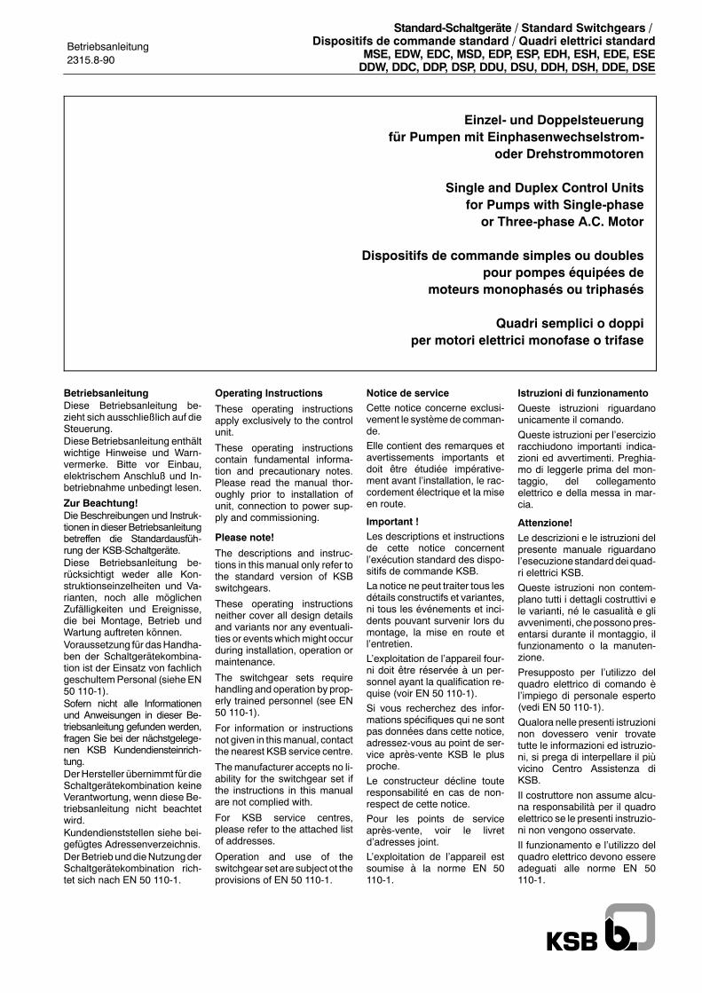
Betriebsanleitung2315.8-90
Standard-Schaltgeräte / Standard Switchgears /Dispositifs de commande standard / Quadri elettrici standard
MSE, EDW, EDC, MSD, EDP, ESP, EDH, ESH, EDE, ESEDDW, DDC, DDP, DSP, DDU, DSU, DDH, DSH, DDE, DSE
Einzel- und Doppelsteuerungfür Pumpen mit Einphasenwechselstrom-
oder Drehstrommotoren
Single and Duplex Control Unitsfor Pumps with Single-phaseor Three-phase A.C. Motor
Dispositifs de commande simples ou doublespour pompes équipées de
moteurs monophasés ou triphasés
Quadri semplici o doppiper motori elettrici monofase o trifase
BetriebsanleitungDiese Betriebsanleitung be-zieht sich ausschließlich auf dieSteuerung.Diese Betriebsanleitung enthältwichtige Hinweise und Warn-vermerke. Bitte vor Einbau,elektrischem Anschluß und In-betriebnahme unbedingt lesen.
Zur Beachtung!Die Beschreibungen und Instruk-tionen in dieser Betriebsanleitungbetreffen die Standardausfüh-rung der KSB-Schaltgeräte.Diese Betriebsanleitung be-rücksichtigt weder alle Kon-struktionseinzelheiten und Va-rianten, noch alle möglichenZufälligkeiten und Ereignisse,die bei Montage, Betrieb undWartung auftreten können.Voraussetzung für dasHandha-ben der Schaltgerätekombina-tion ist der Einsatz von fachlichgeschultemPersonal (sieheEN50 110-1).Sofern nicht alle Informationenund Anweisungen in dieser Be-triebsanleitung gefunden werden,fragen Sie bei der nächstgelege-nen KSB Kundendiensteinrich-tung.DerHersteller übernimmt für dieSchaltgerätekombination keineVerantwortung, wenn diese Be-triebsanleitung nicht beachtetwird.Kundendienststellen siehe bei-gefügtes Adressenverzeichnis.DerBetriebunddieNutzungderSchaltgerätekombination rich-tet sich nach EN 50 110-1.
Operating Instructions
These operating instructionsapply exclusively to the controlunit.
These operating instructionscontain fundamental informa-tion and precautionary notes.Please read the manual thor-oughly prior to installation ofunit, connection to power sup-ply and commissioning.
Please note!
The descriptions and instruc-tions in this manual only refer tothe standard version of KSBswitchgears.
These operating instructionsneither cover all design detailsand variants nor any eventuali-ties or eventswhichmight occurduring installation, operation ormaintenance.
The switchgear sets requirehandling and operation by prop-erly trained personnel (see EN50 110-1).
For information or instructionsnot given in thismanual, contactthe nearest KSB service centre.
Themanufacturer accepts no li-ability for the switchgear set ifthe instructions in this manualare not complied with.
For KSB service centres,please refer to the attached listof addresses.
Operation and use of theswitchgear set are subject ot theprovisions of EN 50 110-1.
Notice de serviceCette notice concerne exclusi-vement le systèmede comman-de.
Elle contient des remarques etavertissements importants etdoit être étudiée impérative-ment avant l�installation, le rac-cordement électrique et la miseen route.
Important !Les descriptions et instructionsde cette notice concernentl�exécution standard des dispo-sitifs de commande KSB.
La notice ne peut traiter tous lesdétails constructifs et variantes,ni tous les événements et inci-dents pouvant survenir lors dumontage, la mise en route etl�entretien.
L�exploitation de l�appareil four-ni doit être réservée à un per-sonnel ayant la qualification re-quise (voir EN 50 110-1).
Si vous recherchez des infor-mations spécifiques qui ne sontpas données dans cette notice,adressez-vous au point de ser-vice après-vente KSB le plusproche.
Le constructeur décline touteresponsabilité en cas de non-respect de cette notice.
Pour les points de serviceaprès-vente, voir le livretd�adresses joint.
L�exploitation de l�appareil estsoumise à la norme EN 50110-1.
Istruzioni di funzionamento
Queste istruzioni riguardanounicamente il comando.
Queste istruzioni per l�esercizioracchiudono importanti indica-zioni ed avvertimenti. Preghia-mo di leggerle prima del mon-taggio, del collegamentoelettrico e della messa in mar-cia.
Attenzione!
Le descrizioni e le istruzioni delpresente manuale riguardanol�esecuzionestandarddei quad-ri elettrici KSB.
Queste istruzioni non contem-plano tutti i dettagli costruttivi ele varianti, né le casualità e gliavvenimenti, chepossonopres-entarsi durante il montaggio, ilfunzionamento o la manuten-zione.
Presupposto per l�utilizzo delquadro elettrico di comando èl�impiego di personale esperto(vedi EN 50 110-1).
Qualora nelle presenti istruzioninon dovessero venir trovatetutte le informazioni ed istruzio-ni, si prega di interpellare il piùvicino Centro Assistenza diKSB.
Il costruttore non assume alcu-na responsabilità per il quadroelettrico se le presenti instruzio-ni non vengono osservate.
Il funzionamento e l�utilizzo delquadro elettrico devono essereadeguati alle norme EN 50110-1.
D
Standard-Schaltgeräte
2
Konformitätserklärung
Hiermit erklären wir, daß die Niederspannungsschaltgerätekombinationen
MSE, EDW, EDC
folgenden einschlägigen Bestimmungen in der jeweils gültigen Fassung entsprechen:Richtlinie 89/336/EWG �Elektromagnetische Verträglichkeit�, Anhang Iund der Richtlinie 73/23/EWG �Niederspannungsrichtlinie�, Anhang III B
Angewendete harmonisierte Normen, insbesondere
EN 50 081 Teil 1/2, EN 50 082 Teil 1/2, EN 60 439
Hansjörg HeinrichLeiter ProduktentwicklungPumpen Gebäudetechnik -- Sparte Objektgeschäft
KSB Aktiengesellschaft, Bahnhofplatz 1, D-91257 Pegnitz
____________________________________________________________________________________________
Konformitätserklärung
Hiermit erklären wir, daß die Niederspannungsschaltgerätekombinationen
DDW, DDC
folgenden einschlägigen Bestimmungen in der jeweils gültigen Fassung entsprechen:Richtlinie 89/336/EWG �Elektromagnetische Verträglichkeit�, Anhang Iund der Richtlinie 73/23/EWG �Niederspannungsrichtlinie�, Anhang III B
Angewendete harmonisierte Normen, insbesondere
EN 50 081 Teil 1/2, EN 50 082 Teil 1/2, EN 60 439
Hansjörg HeinrichLeiter ProduktentwicklungPumpen Gebäudetechnik -- Sparte Objektgeschäft
KSB Aktiengesellschaft, Bahnhofplatz 1, D-91257 Pegnitz
D
Standard-Schaltgeräte
3
Konformitätserklärung
Hiermit erklären wir, daß die Niederspannungsschaltgerätekombinationen
MSD, EDP, ESP, EDH, ESH, EDE, ESE
folgenden einschlägigen Bestimmungen in der jeweils gültigen Fassung entsprechen:Richtlinie 89/336/EWG �Elektromagnetische Verträglichkeit�, Anhang Iund der Richtlinie 73/23/EWG �Niederspannungsrichtlinie�, Anhang III B
Angewendete harmonisierte Normen, insbesondere
EN 50 081 Teil 1/2, EN 50 082 Teil 1/2, EN 60 439
Hansjörg HeinrichLeiter ProduktentwicklungPumpen Gebäudetechnik -- Sparte Objektgeschäft
KSB Aktiengesellschaft, Bahnhofplatz 1, D-91257 Pegnitz
____________________________________________________________________________________________
Konformitätserklärung
Hiermit erklären wir, daß die Niederspannungsschaltgerätekombinationen
DDP, DSP, DDU, DSU, DDH, DSH, DDE, DSE
folgenden einschlägigen Bestimmungen in der jeweils gültigen Fassung entsprechen:Richtlinie 89/336/EWG �Elektromagnetische Verträglichkeit�, Anhang Iund der Richtlinie 73/23/EWG �Niederspannungsrichtlinie�, Anhang III B
Angewendete harmonisierte Normen, insbesondere
EN 50 081 Teil 1/2, EN 50 082 Teil 1/2, EN 60 439
Hansjörg HeinrichLeiter ProduktentwicklungPumpen Gebäudetechnik -- Sparte Objektgeschäft
KSB Aktiengesellschaft, Bahnhofplatz 1, D-91257 Pegnitz
D
GB
Standard-Schaltgeräte
4
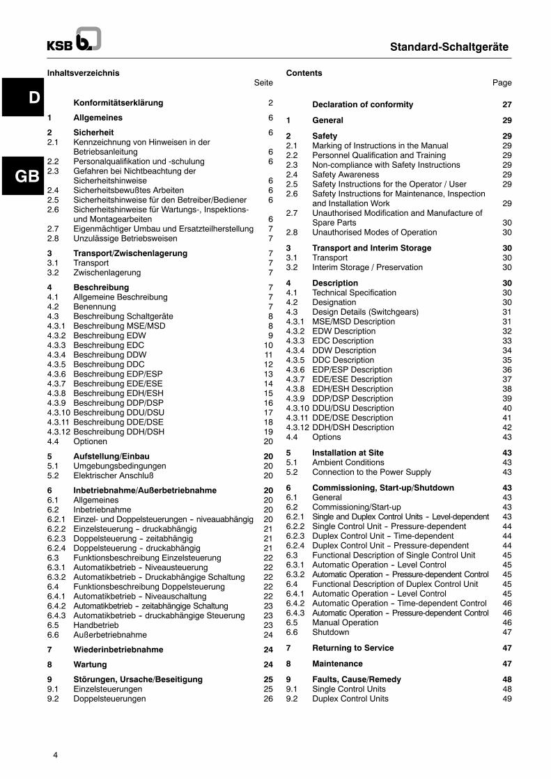
InhaltsverzeichnisSeite
Konformitätserklärung 2
1 Allgemeines 6
2 Sicherheit 62.1 Kennzeichnung von Hinweisen in der
Betriebsanleitung 62.2 Personalqualifikation und -schulung 62.3 Gefahren bei Nichtbeachtung der
Sicherheitshinweise 62.4 Sicherheitsbewußtes Arbeiten 62.5 Sicherheitshinweise für den Betreiber/Bediener 62.6 Sicherheitshinweise für Wartungs-, Inspektions-
und Montagearbeiten 62.7 Eigenmächtiger Umbau und Ersatzteilherstellung 72.8 Unzulässige Betriebsweisen 7
3 Transport/Zwischenlagerung 73.1 Transport 73.2 Zwischenlagerung 7
4 Beschreibung 74.1 Allgemeine Beschreibung 74.2 Benennung 74.3 Beschreibung Schaltgeräte 84.3.1 Beschreibung MSE/MSD 84.3.2 Beschreibung EDW 94.3.3 Beschreibung EDC 104.3.4 Beschreibung DDW 114.3.5 Beschreibung DDC 124.3.6 Beschreibung EDP/ESP 134.3.7 Beschreibung EDE/ESE 144.3.8 Beschreibung EDH/ESH 154.3.9 Beschreibung DDP/DSP 164.3.10 Beschreibung DDU/DSU 174.3.11 Beschreibung DDE/DSE 184.3.12 Beschreibung DDH/DSH 194.4 Optionen 20
5 Aufstellung/Einbau 205.1 Umgebungsbedingungen 205.2 Elektrischer Anschluß 20
6 Inbetriebnahme/Außerbetriebnahme 206.1 Allgemeines 206.2 Inbetriebnahme 206.2.1 Einzel- und Doppelsteuerungen -- niveauabhängig 206.2.2 Einzelsteuerung -- druckabhängig 216.2.3 Doppelsteuerung -- zeitabhängig 216.2.4 Doppelsteuerung -- druckabhängig 216.3 Funktionsbeschreibung Einzelsteuerung 226.3.1 Automatikbetrieb -- Niveausteuerung 226.3.2 Automatikbetrieb -- Druckabhängige Schaltung 226.4 Funktionsbeschreibung Doppelsteuerung 226.4.1 Automatikbetrieb -- Niveauschaltung 226.4.2 Automatikbetrieb -- zeitabhängige Schaltung 236.4.3 Automatikbetrieb -- druckabhängige Steuerung 236.5 Handbetrieb 236.6 Außerbetriebnahme 24
7 Wiederinbetriebnahme 24
8 Wartung 24
9 Störungen, Ursache/Beseitigung 259.1 Einzelsteuerungen 259.2 Doppelsteuerungen 26
ContentsPage
Declaration of conformity 27
1 General 29
2 Safety 292.1 Marking of Instructions in the Manual 292.2 Personnel Qualification and Training 292.3 Non-compliance with Safety Instructions 292.4 Safety Awareness 292.5 Safety Instructions for the Operator / User 292.6 Safety Instructions for Maintenance, Inspection
and Installation Work 292.7 Unauthorised Modification and Manufacture of
Spare Parts 302.8 Unauthorised Modes of Operation 30
3 Transport and Interim Storage 303.1 Transport 303.2 Interim Storage / Preservation 30
4 Description 304.1 Technical Specification 304.2 Designation 304.3 Design Details (Switchgears) 314.3.1 MSE/MSD Description 314.3.2 EDW Description 324.3.3 EDC Description 334.3.4 DDW Description 344.3.5 DDC Description 354.3.6 EDP/ESP Description 364.3.7 EDE/ESE Description 374.3.8 EDH/ESH Description 384.3.9 DDP/DSP Description 394.3.10 DDU/DSU Description 404.3.11 DDE/DSE Description 414.3.12 DDH/DSH Description 424.4 Options 43
5 Installation at Site 435.1 Ambient Conditions 435.2 Connection to the Power Supply 43
6 Commissioning, Start-up/Shutdown 436.1 General 436.2 Commissioning/Start-up 436.2.1 Single and Duplex Control Units -- Level-dependent 436.2.2 Single Control Unit -- Pressure-dependent 446.2.3 Duplex Control Unit -- Time-dependent 446.2.4 Duplex Control Unit -- Pressure-dependent 446.3 Functional Description of Single Control Unit 456.3.1 Automatic Operation -- Level Control 456.3.2 Automatic Operation -- Pressure-dependent Control 456.4 Functional Description of Duplex Control Unit 456.4.1 Automatic Operation -- Level Control 456.4.2 Automatic Operation -- Time-dependent Control 466.4.3 Automatic Operation -- Pressure-dependent Control 466.5 Manual Operation 466.6 Shutdown 47
7 Returning to Service 47
8 Maintenance 47
9 Faults, Cause/Remedy 489.1 Single Control Units 489.2 Duplex Control Units 49
F
I
Standard-Schaltgeräte
5
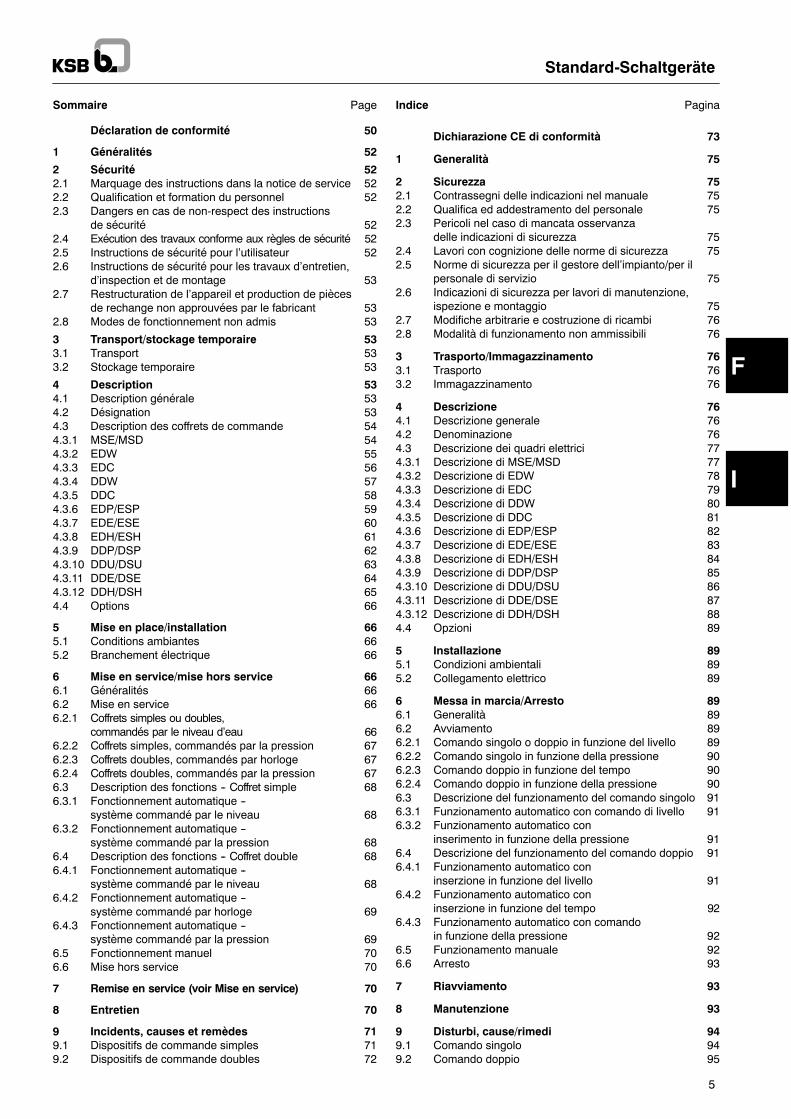
Sommaire Page
Déclaration de conformité 50
1 Généralités 52
2 Sécurité 522.1 Marquage des instructions dans la notice de service 522.2 Qualification et formation du personnel 522.3 Dangers en cas de non-respect des instructions
de sécurité 522.4 Exécution des travaux conforme aux règles de sécurité 522.5 Instructions de sécurité pour l�utilisateur 522.6 Instructions de sécurité pour les travaux d�entretien,
d�inspection et de montage 532.7 Restructuration de l�appareil et production de pièces
de rechange non approuvées par le fabricant 532.8 Modes de fonctionnement non admis 53
3 Transport/stockage temporaire 533.1 Transport 533.2 Stockage temporaire 53
4 Description 534.1 Description générale 534.2 Désignation 534.3 Description des coffrets de commande 544.3.1 MSE/MSD 544.3.2 EDW 554.3.3 EDC 564.3.4 DDW 574.3.5 DDC 584.3.6 EDP/ESP 594.3.7 EDE/ESE 604.3.8 EDH/ESH 614.3.9 DDP/DSP 624.3.10 DDU/DSU 634.3.11 DDE/DSE 644.3.12 DDH/DSH 654.4 Options 66
5 Mise en place/installation 665.1 Conditions ambiantes 665.2 Branchement électrique 66
6 Mise en service/mise hors service 666.1 Généralités 666.2 Mise en service 666.2.1 Coffrets simples ou doubles,
commandés par le niveau d�eau 666.2.2 Coffrets simples, commandés par la pression 676.2.3 Coffrets doubles, commandés par horloge 676.2.4 Coffrets doubles, commandés par la pression 676.3 Description des fonctions -- Coffret simple 686.3.1 Fonctionnement automatique --
système commandé par le niveau 686.3.2 Fonctionnement automatique --
système commandé par la pression 686.4 Description des fonctions -- Coffret double 686.4.1 Fonctionnement automatique --
système commandé par le niveau 686.4.2 Fonctionnement automatique --
système commandé par horloge 696.4.3 Fonctionnement automatique --
système commandé par la pression 696.5 Fonctionnement manuel 706.6 Mise hors service 70
7 Remise en service (voir Mise en service) 70
8 Entretien 70
9 Incidents, causes et remèdes 719.1 Dispositifs de commande simples 719.2 Dispositifs de commande doubles 72
Indice Pagina
Dichiarazione CE di conformità 73
1 Generalità 75
2 Sicurezza 752.1 Contrassegni delle indicazioni nel manuale 752.2 Qualifica ed addestramento del personale 752.3 Pericoli nel caso di mancata osservanza
delle indicazioni di sicurezza 752.4 Lavori con cognizione delle norme di sicurezza 752.5 Norme di sicurezza per il gestore dell�impianto/per il
personale di servizio 752.6 Indicazioni di sicurezza per lavori di manutenzione,
ispezione e montaggio 752.7 Modifiche arbitrarie e costruzione di ricambi 762.8 Modalità di funzionamento non ammissibili 76
3 Trasporto/Immagazzinamento 763.1 Trasporto 763.2 Immagazzinamento 76
4 Descrizione 764.1 Descrizione generale 764.2 Denominazione 764.3 Descrizione dei quadri elettrici 774.3.1 Descrizione di MSE/MSD 774.3.2 Descrizione di EDW 784.3.3 Descrizione di EDC 794.3.4 Descrizione di DDW 804.3.5 Descrizione di DDC 814.3.6 Descrizione di EDP/ESP 824.3.7 Descrizione di EDE/ESE 834.3.8 Descrizione di EDH/ESH 844.3.9 Descrizione di DDP/DSP 854.3.10 Descrizione di DDU/DSU 864.3.11 Descrizione di DDE/DSE 874.3.12 Descrizione di DDH/DSH 884.4 Opzioni 89
5 Installazione 895.1 Condizioni ambientali 895.2 Collegamento elettrico 89
6 Messa in marcia/Arresto 896.1 Generalità 896.2 Avviamento 896.2.1 Comando singolo o doppio in funzione del livello 896.2.2 Comando singolo in funzione della pressione 906.2.3 Comando doppio in funzione del tempo 906.2.4 Comando doppio in funzione della pressione 906.3 Descrizione del funzionamento del comando singolo 916.3.1 Funzionamento automatico con comando di livello 916.3.2 Funzionamento automatico con
inserimento in funzione della pressione 916.4 Descrizione del funzionamento del comando doppio 916.4.1 Funzionamento automatico con
inserzione in funzione del livello 916.4.2 Funzionamento automatico con
inserzione in funzione del tempo 926.4.3 Funzionamento automatico con comando
in funzione della pressione 926.5 Funzionamento manuale 926.6 Arresto 93
7 Riavviamento 93
8 Manutenzione 93
9 Disturbi, cause/rimedi 949.1 Comando singolo 949.2 Comando doppio 95
DAchtung
Standard-Schaltgeräte
6
1 AllgemeinesDieses KSB-Gerät ist nach dem Stand der Technik ent-wickelt, mit größter Sorgfalt gefertigt und unterliegt einerständigen Qualitätskontrolle.Die vorliegende Betriebsanleitung soll es erleichtern,das Gerät kennenzulernen und seine bestimmungsge-mäßen Einsatzmöglichkeiten zu nutzen.Die Betriebsanleitung enthält wichtige Hinweise, um dasGerät sicher, sachgerecht und wirtschaftlich zu betrei-ben. Ihre Beachtung ist erforderlich, um die Zuverlässig-keit und die lange Lebensdauer desGeräts sicherzustel-len und um Gefahren zu vermeiden.Die Betriebsanleitung berücksichtigt nicht die ortsbezo-genen Bestimmungen, für deren Einhaltung -- auch sei-tens des hinzugezogenen Montagepersonals -- der Be-treiber verantwortlich ist.Dieses Gerät darf nicht über die in der technischen Doku-mentation festgelegtenWerte, bezüglich Betriebsspannung,Netznennfrequenz, Umgebungstemperatur, Schaltleistungundandere in derBetriebsanleitungoderVertragsdokumen-tation enthaltenen Anweisungen betrieben werden.Das Fabrikschild nennt die Baureihe/-größe, die wichtig-stenBetriebsdaten und dieSeriennummer, die bei Rück-frage, Nachbestellung und insbesondere bei Bestellungvon Ersatzteilen stets anzugeben ist.Sofernzusätzliche InformationenoderHinweisebenötigtwerden sowie im Schadensfall wenden Sie sich bitte andie nächstgelegene KSB-Kundendiensteinrichtung.
2 SicherheitDieseBetriebsanleitungenthält grundlegendeHinweise,die bei Aufstellung, Betrieb und Wartung zu beachtensind. Daher ist diese Betriebsanleitung unbedingt vorMontage und Inbetriebnahme vom Monteur sowie demzuständigen Fachpersonal/Betreiber zu lesen und mußständig am Einsatzort der Maschine verfügbar sein.Es sind nicht nur die unter diesemHauptpunkt Sicherheitaufgeführten, allgemeinen Sicherheitshinweise zu be-achten, sondern auchdie unter denanderenHauptpunk-ten aufgeführten speziellen Sicherheitshinweise.
2.1 Kennzeichnung von Hinweisen in derBetriebsanleitung
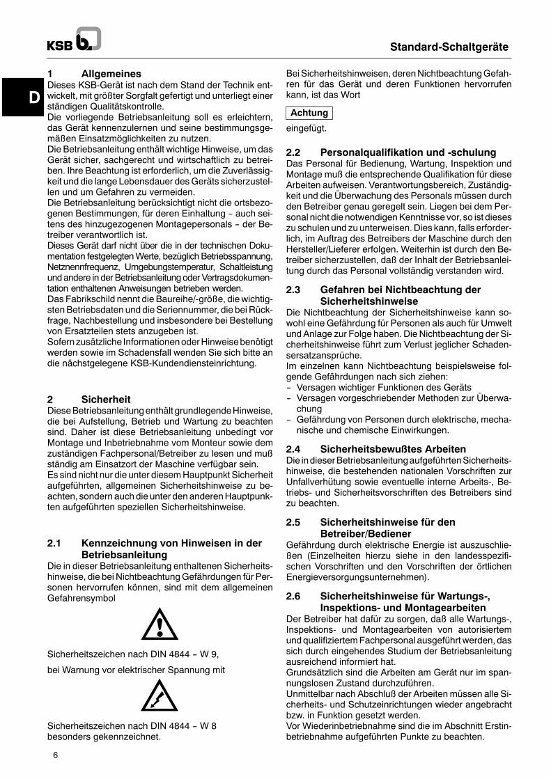
Die in dieser Betriebsanleitung enthaltenen Sicherheits-hinweise, die bei NichtbeachtungGefährdungen für Per-sonen hervorrufen können, sind mit dem allgemeinenGefahrensymbol
Sicherheitszeichen nach DIN 4844 -- W 9,
bei Warnung vor elektrischer Spannung mit
Sicherheitszeichen nach DIN 4844 -- W 8besonders gekennzeichnet.
BeiSicherheitshinweisen, derenNichtbeachtungGefah-ren für das Gerät und deren Funktionen hervorrufenkann, ist das Wort
eingefügt.
2.2 Personalqualifikation und -schulungDas Personal für Bedienung, Wartung, Inspektion undMontage muß die entsprechende Qualifikation für dieseArbeiten aufweisen. Verantwortungsbereich, Zuständig-keit und die Überwachung des Personals müssen durchden Betreiber genau geregelt sein. Liegen bei dem Per-sonal nicht die notwendigenKenntnisse vor, so ist dieseszu schulen und zu unterweisen.Dies kann, falls erforder-lich, im Auftrag des Betreibers der Maschine durch denHersteller/Lieferer erfolgen. Weiterhin ist durch den Be-treiber sicherzustellen, daß der Inhalt der Betriebsanlei-tung durch das Personal vollständig verstanden wird.
2.3 Gefahren bei Nichtbeachtung derSicherheitshinweise
Die Nichtbeachtung der Sicherheitshinweise kann so-wohl eine Gefährdung für Personen als auch für Umweltund Anlage zur Folge haben. Die Nichtbeachtung der Si-cherheitshinweise führt zum Verlust jeglicher Schaden-sersatzansprüche.Im einzelnen kann Nichtbeachtung beispielsweise fol-gende Gefährdungen nach sich ziehen:-- Versagen wichtiger Funktionen des Geräts-- Versagen vorgeschriebender Methoden zur Überwa-chung
-- Gefährdung von Personen durch elektrische, mecha-nische und chemische Einwirkungen.
2.4 Sicherheitsbewußtes ArbeitenDie indieserBetriebsanleitungaufgeführtenSicherheits-hinweise, die bestehenden nationalen Vorschriften zurUnfallverhütung sowie eventuelle interne Arbeits-, Be-triebs- und Sicherheitsvorschriften des Betreibers sindzu beachten.
2.5 Sicherheitshinweise für denBetreiber/Bediener
Gefährdung durch elektrische Energie ist auszuschlie-ßen (Einzelheiten hierzu siehe in den landesspezifi-schen Vorschriften und den Vorschriften der örtlichenEnergieversorgungsunternehmen).
2.6 Sicherheitshinweise für Wartungs-,Inspektions- und Montagearbeiten
Der Betreiber hat dafür zu sorgen, daß alle Wartungs-,Inspektions- und Montagearbeiten von autorisiertemundqualifiziertemFachpersonal ausgeführtwerden, dassich durch eingehendes Studium der Betriebsanleitungausreichend informiert hat.Grundsätzlich sind die Arbeiten am Gerät nur im span-nungslosen Zustand durchzuführen.Unmittelbar nach Abschluß der Arbeitenmüssen alle Si-cherheits- und Schutzeinrichtungen wieder angebrachtbzw. in Funktion gesetzt werden.Vor Wiederinbetriebnahme sind die im Abschnitt Erstin-betriebnahme aufgeführten Punkte zu beachten.
D
Standard-Schaltgeräte
7
2.7 Eigenmächtiger Umbau undErsatzteilherstellung
Umbau oder Veränderungen des Geräts sind nur nachAbsprache mit dem Hersteller zulässig. Originalersatz-teileundvomHersteller autorisiertesZubehördienenderSicherheit. Die Verwendung anderer Teile kann die Haf-tung für die daraus entstehenden Folgen aufheben.
2.8 Unzulässige BetriebsweisenDie Betriebssicherheit des gelieferten Geräts ist nur beibestimmungsgemäßer Verwendung gewährleistet. Diein der Dokumentation angegebenen Grenzwerte dürfenauf keinen Fall überschritten werden.
3 Transport/Zwischenlagerung3.1 TransportDer Transport des Gerätes muß fachgerecht erfolgen.Standschränke sind stehend zu transportieren, da sichsonst die Montageplatte durchbiegt. Das Schaltgerätwurde vor dem Versand auf Einhaltung aller angegebe-nen Daten geprüft. Das Gerät sollte sich deshalb beiEmpfang in elektrisch und mechanisch einwandfreiemZustandbefinden.Umsichhiervonzuüberzeugen, emp-fehlenwir, dasSchaltgerät bei derÜbernahmeaufTrans-portschädenzuuntersuchen. ImFalle vonBeanstandun-gen ist zusammen mit dem Überbringer eineSchadensaufnahme abzufassen.
3.2 ZwischenlagerungDieZwischenlagerungmuß trockenunderschütterungs-frei und möglichst in der Originalverpackung erfolgen.Die Umgebungstemperatur darf nicht außerhalb desBe-reiches --10 !C bis +50 !C liegen.
4 Beschreibung4.1 Allgemeine BeschreibungDie Beschreibungen und Instruktionen in dieser Be-triebsanleitung betreffen die Standardausführung mitOriginal-KSB-Steuergeräten.Die KSB-Standardschaltgeräte sind Niederspannungs-schaltgerätekombinationen nach EN 60 439 für dieSteuerung und den Schutz eines oder zweier Einpha-senwechselstrommotoren bzw. Drehstromantrieben.Der oder die Motoren werden bis einschließlich 4 kW di-rekt (1~ und 3~) und ab einer Leistung von 5,5 kW (nur3~) im Stern-Dreieck-Anlauf eingeschaltet.
4.2 BenennungStandardschaltgeräteDie Bezeichnung der Schaltgeräte setzt sich aus Buch-staben und Ziffern zusammen (Ausnahmen MSE/MSDsiehe Beschreibung).
E/D D/S P/C/E/W/U/H -/X/L 40 .1
EinzelsteuerungDoppelsteuerung
DirektanlaufStern-Dreieck-Anlauf
Potentialfreie KontakteC Kondensator 1)Ex-Schutz 2)WechselstromUhr (zeitgesteuert)Hyamation (Druckerhöhung)
�kein Buchstabe� (Standard)X SonderausführungStaudruckmessung (Lufteinperlverfahren)
Maximale Stromstärke x 10
Kennziffer
Weitere Kennzeichnungen bleiben ohne Auswirkung auf die indieser Betriebsanleitung beschriebenen Funktionen.Diese weiteren Bezeichnungen kennzeichnen z. B. länderspe-zifische Versionen hinsichtlich des Ausstattungsumfangs,z. B. Suffix EUHauptschalter und Steuertransformator Seriez. B. Suffix FLSFreiluftschrank.
1) Motor ohne Betriebskondensator. Der Kondensator für denMo-tor ist im Schaltgerät eingebaut.
2) Ex-Schutz durch spezielles Relais. Das Schaltgerät darf nichtim explosionsgefährdeten Bereich installiert werden.
D
Standard-Schaltgeräte
8
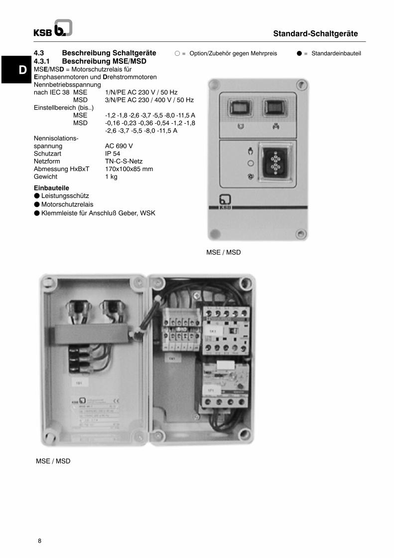
4.3 Beschreibung Schaltgeräte f = Option/Zubehör gegen Mehrpreis F = Standardeinbauteil4.3.1 Beschreibung MSE/MSDMSE/MSD = Motorschutzrelais fürEinphasenmotoren und DrehstrommotorenNennbetriebsspannungnach IEC 38 MSE 1/N/PE AC 230 V / 50 Hz
MSD 3/N/PE AC 230 / 400 V / 50 HzEinstellbereich (bis..)
MSE -1,2 -1,8 -2,6 -3,7 -5,5 -8,0 -11,5 AMSD -0,16 -0,23 -0,36 -0,54 -1,2 -1,8
-2,6 -3,7 -5,5 -8,0 -11,5 ANennisolations-spannung AC 690 VSchutzart IP 54Netzform TN-C-S-NetzAbmessung HxBxT 170x100x85 mmGewicht 1 kg
EinbauteileF LeistungsschützFMotorschutzrelaisF Klemmleiste für Anschluß Geber, WSK
MSE / MSD
MSE / MSD
D
Standard-Schaltgeräte
9
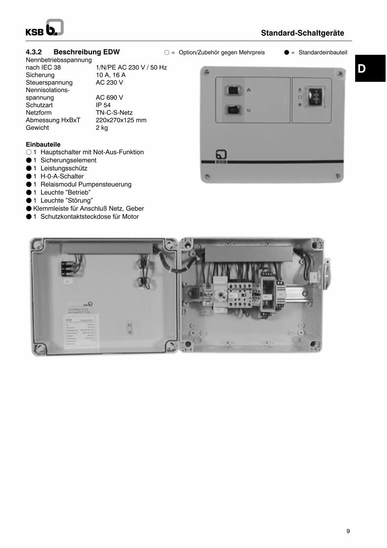
4.3.2 Beschreibung EDW f = Option/Zubehör gegen Mehrpreis F = StandardeinbauteilNennbetriebsspannungnach IEC 38 1/N/PE AC 230 V / 50 HzSicherung 10 A, 16 ASteuerspannung AC 230 VNennisolations-spannung AC 690 VSchutzart IP 54Netzform TN-C-S-NetzAbmessung HxBxT 220x270x125 mmGewicht 2 kg
Einbauteilef 1 Hauptschalter mit Not-Aus-FunktionF 1 SicherungselementF 1 LeistungsschützF 1 H-0-A-SchalterF 1 Relaismodul PumpensteuerungF 1 Leuchte �Betrieb�F 1 Leuchte �Störung�F Klemmleiste für Anschluß Netz, GeberF 1 Schutzkontaktsteckdose für Motor
D
Standard-Schaltgeräte
10
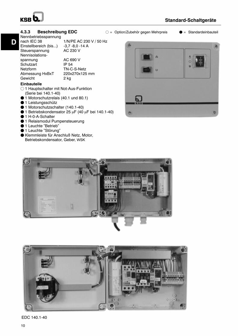
4.3.3 Beschreibung EDC f = Option/Zubehör gegen Mehrpreis F = StandardeinbauteilNennbetriebsspannungnach IEC 38 1/N/PE AC 230 V / 50 HzEinstellbereich (bis...) -3,7 -8,0 -14 ASteuerspannung AC 230 VNennisolations-spannung AC 690 VSchutzart IP 54Netzform TN-C-S-NetzAbmessung HxBxT 220x270x125 mmGewicht 2 kg
Einbauteilef 1 Hauptschalter mit Not-Aus-Funktion(Serie bei 140.1-40)
F 1 Motorschutzrelais (40.1 und 80.1)F 1 LeistungsschützF 1 Motorschutzschalter (140.1-40)F 1 Betriebskondensator 25 mF (40 mF bei 140.1-40)F 1 H-0-A-SchalterF 1 Relaismodul PumpensteuerungF 1 Leuchte �Betrieb�F 1 Leuchte �Störung�F Klemmleiste für Anschluß Netz, Motor,Betriebskondensator, Geber, WSK
EDC
EDC 140.1-40
D
Standard-Schaltgeräte
11
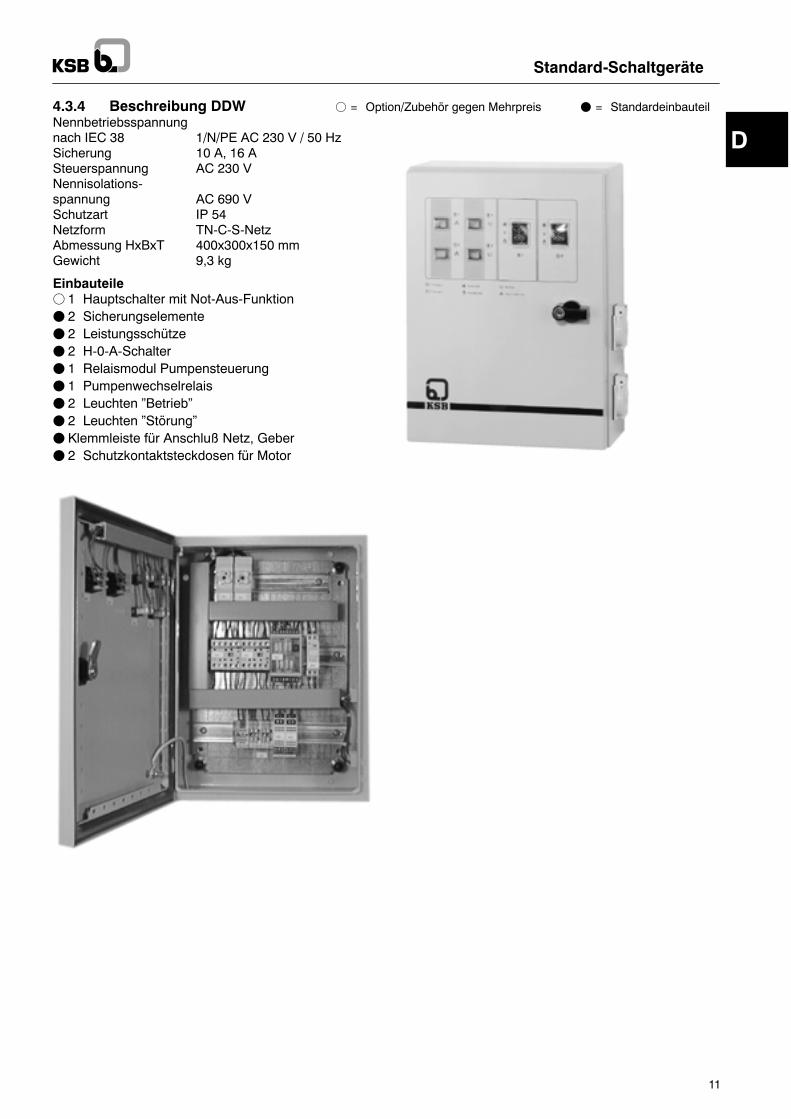
4.3.4 Beschreibung DDW f = Option/Zubehör gegen Mehrpreis F = StandardeinbauteilNennbetriebsspannungnach IEC 38 1/N/PE AC 230 V / 50 HzSicherung 10 A, 16 ASteuerspannung AC 230 VNennisolations-spannung AC 690 VSchutzart IP 54Netzform TN-C-S-NetzAbmessung HxBxT 400x300x150 mmGewicht 9,3 kg
Einbauteilef 1 Hauptschalter mit Not-Aus-FunktionF 2 SicherungselementeF 2 LeistungsschützeF 2 H-0-A-SchalterF 1 Relaismodul PumpensteuerungF 1 PumpenwechselrelaisF 2 Leuchten �Betrieb�F 2 Leuchten �Störung�F Klemmleiste für Anschluß Netz, GeberF 2 Schutzkontaktsteckdosen für Motor
D
Standard-Schaltgeräte
12
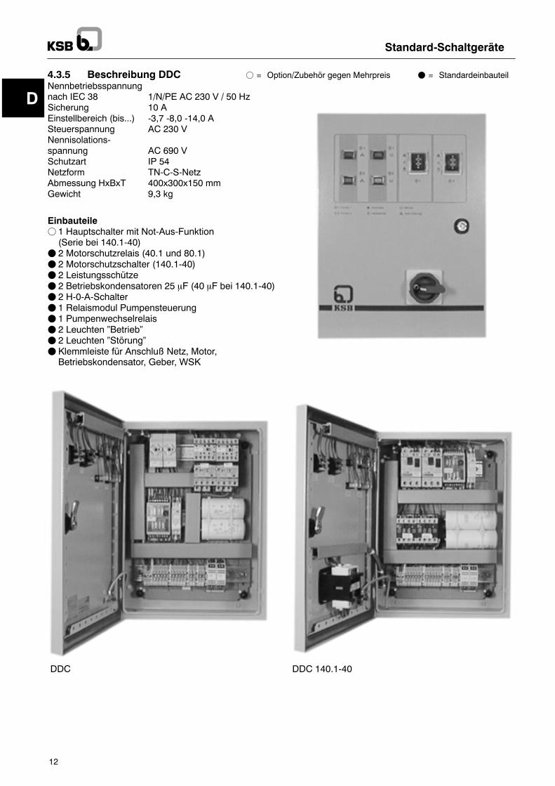
4.3.5 Beschreibung DDC f = Option/Zubehör gegen Mehrpreis F = StandardeinbauteilNennbetriebsspannungnach IEC 38 1/N/PE AC 230 V / 50 HzSicherung 10 AEinstellbereich (bis...) -3,7 -8,0 -14,0 ASteuerspannung AC 230 VNennisolations-spannung AC 690 VSchutzart IP 54Netzform TN-C-S-NetzAbmessung HxBxT 400x300x150 mmGewicht 9,3 kg
Einbauteilef 1 Hauptschalter mit Not-Aus-Funktion(Serie bei 140.1-40)
F 2 Motorschutzrelais (40.1 und 80.1)F 2 Motorschutzschalter (140.1-40)F 2 LeistungsschützeF 2 Betriebskondensatoren 25 mF (40 mF bei 140.1-40)F 2 H-0-A-SchalterF 1 Relaismodul PumpensteuerungF 1 PumpenwechselrelaisF 2 Leuchten �Betrieb�F 2 Leuchten �Störung�F Klemmleiste für Anschluß Netz, Motor,Betriebskondensator, Geber, WSK
DDC DDC 140.1-40
D
Standard-Schaltgeräte
13
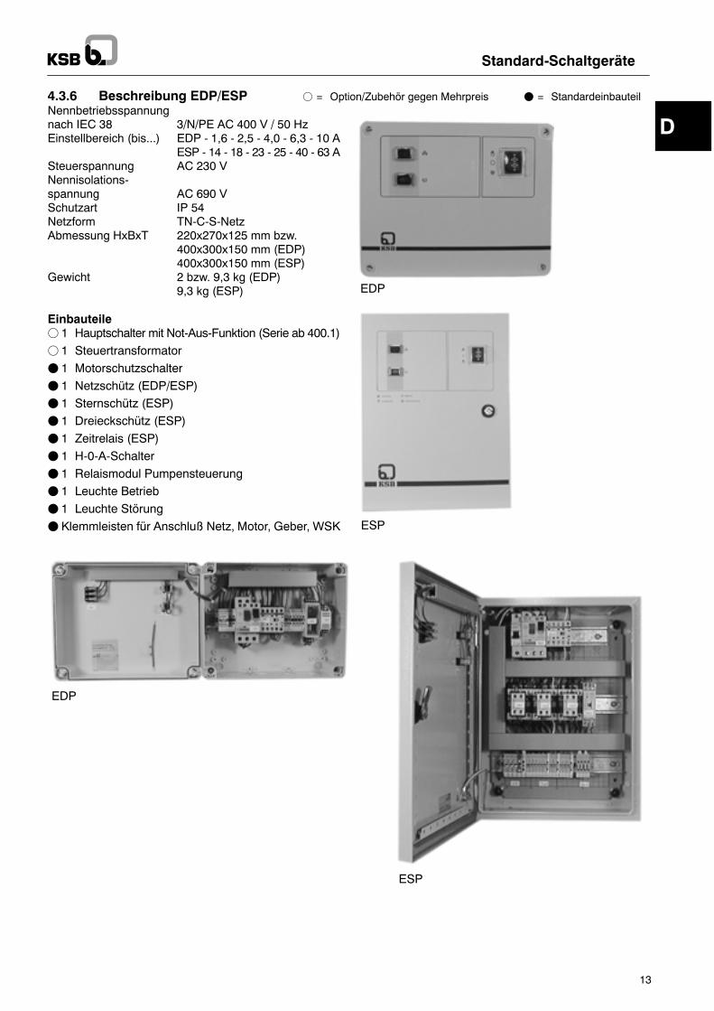
4.3.6 Beschreibung EDP/ESP f = Option/Zubehör gegen Mehrpreis F = StandardeinbauteilNennbetriebsspannungnach IEC 38 3/N/PE AC 400 V / 50 HzEinstellbereich (bis...) EDP - 1,6 - 2,5 - 4,0 - 6,3 - 10 A
ESP - 14 - 18 - 23 - 25 - 40 - 63 ASteuerspannung AC 230 VNennisolations-spannung AC 690 VSchutzart IP 54Netzform TN-C-S-NetzAbmessung HxBxT 220x270x125 mm bzw.
400x300x150 mm (EDP)400x300x150 mm (ESP)
Gewicht 2 bzw. 9,3 kg (EDP)9,3 kg (ESP)
Einbauteilef 1 Hauptschalter mit Not-Aus-Funktion (Serie ab 400.1)
f 1 Steuertransformator
F 1 Motorschutzschalter
F 1 Netzschütz (EDP/ESP)
F 1 Sternschütz (ESP)
F 1 Dreieckschütz (ESP)
F 1 Zeitrelais (ESP)
F 1 H-0-A-Schalter
F 1 Relaismodul Pumpensteuerung
F 1 Leuchte Betrieb
F 1 Leuchte Störung
F Klemmleisten für Anschluß Netz, Motor, Geber, WSK
EDP
ESP
EDP
ESP
D
Standard-Schaltgeräte
14
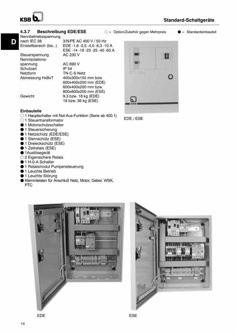
4.3.7 Beschreibung EDE/ESE f = Option/Zubehör gegen Mehrpreis F = StandardeinbauteilNennbetriebsspannungnach IEC 38 3/N/PE AC 400 V / 50 HzEinstellbereich (bis...) EDE -1,6 -2,5 -4,0 -6,3 -10 A
ESE -14 -18 -23 -25 -40 -63 ASteuerspannung AC 230 VNennisolations-spannung AC 690 VSchutzart IP 54Netzform TN-C-S-NetzAbmessung HxBxT 400x300x150 mm bzw.
600x400x200 mm (EDE)600x400x200 mm bzw.800x600x200 mm (ESE)
Gewicht 9,3 bzw. 18 kg (EDE)18 bzw. 36 kg (ESE)
Einbauteilef 1 Hauptschalter mit Not-Aus-Funktion (Serie ab 400.1)f 1 SteuertransformatorF 1 MotorschutzschalterF 1 SteuersicherungF 1 Netzschütz (EDE/ESE)F 1 Sternschütz (ESE)F 1 Dreieckschütz (ESE)F 1 Zeitrelais (ESE)F 1Auslösegerätf 2 Eigensichere RelaisF 1 H-0-A SchalterF 1 Relaismodul PumpensteuerungF 1 Leuchte BetriebF 1 Leuchte StörungF Klemmleisten für Anschluß Netz, Motor, Geber, WSK,PTC
EDE / ESE
ESEEDE
D
Standard-Schaltgeräte
15
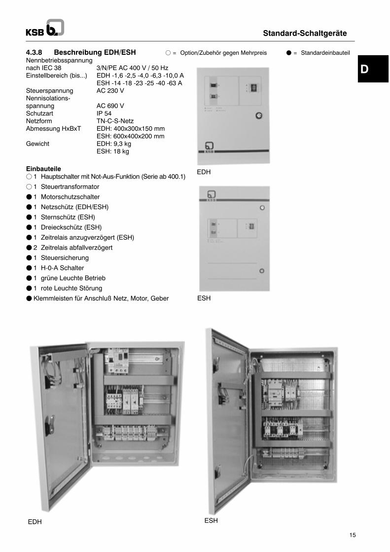
4.3.8 Beschreibung EDH/ESH f = Option/Zubehör gegen Mehrpreis F = StandardeinbauteilNennbetriebsspannungnach IEC 38 3/N/PE AC 400 V / 50 HzEinstellbereich (bis...) EDH -1,6 -2,5 -4,0 -6,3 -10,0 A
ESH -14 -18 -23 -25 -40 -63 ASteuerspannung AC 230 VNennisolations-spannung AC 690 VSchutzart IP 54Netzform TN-C-S-NetzAbmessung HxBxT EDH: 400x300x150 mm
ESH: 600x400x200 mmGewicht EDH: 9,3 kg
ESH: 18 kg
Einbauteilef 1 Hauptschalter mit Not-Aus-Funktion (Serie ab 400.1)
f 1 Steuertransformator
F 1 Motorschutzschalter
F 1 Netzschütz (EDH/ESH)
F 1 Sternschütz (ESH)
F 1 Dreieckschütz (ESH)
F 1 Zeitrelais anzugverzögert (ESH)
F 2 Zeitrelais abfallverzögert
F 1 Steuersicherung
F 1 H-0-A Schalter
F 1 grüne Leuchte Betrieb
F 1 rote Leuchte Störung
F Klemmleisten für Anschluß Netz, Motor, Geber
EDH
ESH
EDH ESH
D
Standard-Schaltgeräte
16
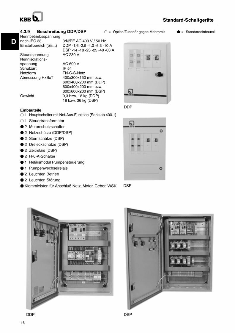
4.3.9 Beschreibung DDP/DSP f = Option/Zubehör gegen Mehrpreis F = StandardeinbauteilNennbetriebsspannungnach IEC 38 3/N/PE AC 400 V / 50 HzEinstellbereich (bis...) DDP -1,6 -2,5 -4,0 -6,3 -10 A
DSP -14 -18 -23 -25 -40 -63 ASteuerspannung AC 230 VNennisolations-spannung AC 690 VSchutzart IP 54Netzform TN-C-S-NetzAbmessung HxBxT 400x300x150 mm bzw.
600x400x200 mm (DDP)600x400x200 mm bzw.800x600x200 mm (DSP)
Gewicht 9,3 bzw. 18 kg (DDP)18 bzw. 36 kg (DSP)
Einbauteilef 1 Hauptschalter mit Not-Aus-Funktion (Serie ab 400.1)
f 1 Steuertransformator
F 2 Motorschutzschalter
F 2 Netzschütze (DDP/DSP)
F 2 Sternschütze (DSP)
F 2 Dreieckschütze (DSP)
F 2 Zeitrelais (DSP)
F 2 H-0-A-Schalter
F 1 Relaismodul Pumpensteuerung
F 1 Pumpenwechselrelais
F 2 Leuchten Betrieb
F 2 Leuchten Störung
F Klemmleisten für Anschluß Netz, Motor, Geber, WSK
DDP
DSP
DDP DSP
D
Standard-Schaltgeräte
17
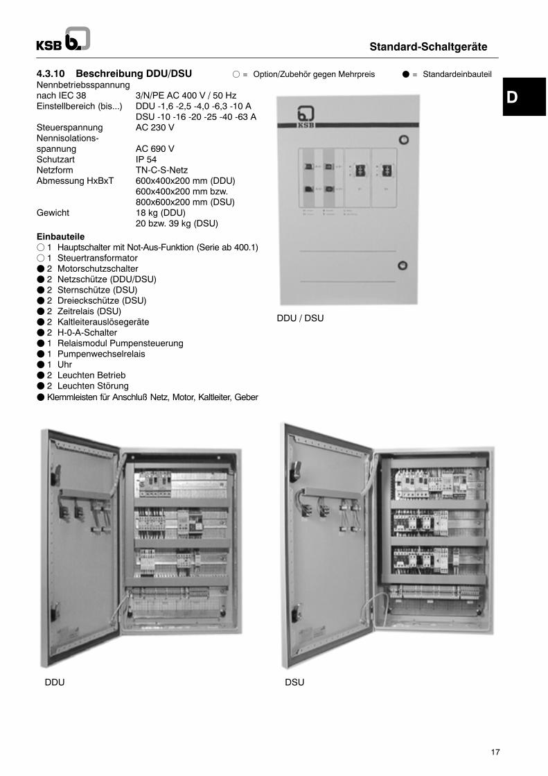
4.3.10 Beschreibung DDU/DSU f = Option/Zubehör gegen Mehrpreis F = StandardeinbauteilNennbetriebsspannungnach IEC 38 3/N/PE AC 400 V / 50 HzEinstellbereich (bis...) DDU -1,6 -2,5 -4,0 -6,3 -10 A
DSU -10 -16 -20 -25 -40 -63 ASteuerspannung AC 230 VNennisolations-spannung AC 690 VSchutzart IP 54Netzform TN-C-S-NetzAbmessung HxBxT 600x400x200 mm (DDU)
600x400x200 mm bzw.800x600x200 mm (DSU)
Gewicht 18 kg (DDU)20 bzw. 39 kg (DSU)
Einbauteilef 1 Hauptschalter mit Not-Aus-Funktion (Serie ab 400.1)f 1 SteuertransformatorF 2 MotorschutzschalterF 2 Netzschütze (DDU/DSU)F 2 Sternschütze (DSU)F 2 Dreieckschütze (DSU)F 2 Zeitrelais (DSU)F 2 KaltleiterauslösegeräteF 2 H-0-A-SchalterF 1 Relaismodul PumpensteuerungF 1 PumpenwechselrelaisF 1 UhrF 2 Leuchten BetriebF 2 Leuchten StörungF Klemmleisten für Anschluß Netz, Motor, Kaltleiter, Geber
DDU / DSU
fehltDDU folgt neuvon BOE
DDU DSU
D
Standard-Schaltgeräte
18
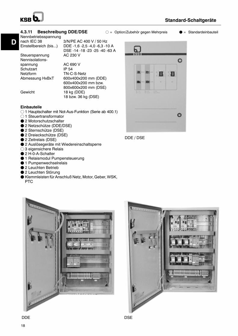
4.3.11 Beschreibung DDE/DSE f = Option/Zubehör gegen Mehrpreis F = StandardeinbauteilNennbetriebsspannungnach IEC 38 3/N/PE AC 400 V / 50 HzEinstellbereich (bis...) DDE -1,6 -2,5 -4,0 -6,3 -10 A
DSE -14 -18 -23 -25 -40 -63 ASteuerspannung AC 230 VNennisolations-spannung AC 690 VSchutzart IP 54Netzform TN-C-S-NetzAbmessung HxBxT 600x400x200 mm (DDE)
600x400x200 mm bzw.800x600x200 mm (DSE)
Gewicht 18 kg (DDE)18 bzw. 36 kg (DSE)
Einbauteilef 1 Hauptschalter mit Not-Aus-Funktion (Serie ab 400.1)f 1 SteuertransformatorF 2 MotorschutzschalterF 2 Netzschütze (DDE/DSE)F 2 Sternschütze (DSE)F 2 Dreieckschütze (DSE)F 2 Zeitrelais (DSE)F 2 Auslösegeräte mit Wiedereinschaltsperref 3 eigensichere RelaisF 2 H-0-A-SchalterF 1 Relaismodul PumpensteuerungF 1 PumpenwechselrelaisF 2 Leuchten BetriebF 2 Leuchten StörungF Klemmleisten für AnschlußNetz,Motor,Geber,WSK,PTC
DDE / DSE
DDE DSE
D
Standard-Schaltgeräte
19
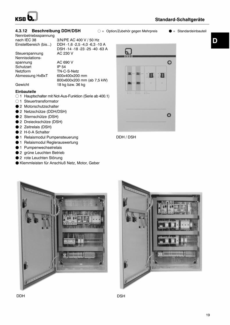
4.3.12 Beschreibung DDH/DSH f = Option/Zubehör gegen Mehrpreis F = StandardeinbauteilNennbetriebsspannungnach IEC 38 3/N/PE AC 400 V / 50 HzEinstellbereich (bis...) DDH -1,6 -2,5 -4,0 -6,3 -10 A
DSH -14 -18 -23 -25 -40 -63 ASteuerspannung AC 230 VNennisolations-spannung AC 690 VSchutzart IP 54Netzform TN-C-S-NetzAbmessung HxBxT 600x400x200 mm
800x600x200 mm (ab 7,5 kW)Gewicht 18 kg bzw. 36 kg
Einbauteilef 1 Hauptschalter mit Not-Aus-Funktion (Serie ab 400.1)f 1 SteuertransformatorF 2 MotorschutzschalterF 2 Netzschütze (DDH/DSH)F 2 Sternschütze (DSH)F 2 Dreieckschütze (DSH)F 2 Zeitrelais (DSH)F 2 H-0-A SchalterF 1 Relaismodul PumpensteuerungF 1 Relaismodul ReglerauswertungF 1 PumpenwechselrelaisF 2 grüne Leuchten BetriebF 2 rote Leuchten StörungF Klemmleisten für Anschluß Netz, Motor, Geber
DDH / DSH
DDH DSH
D
Achtung
Standard-Schaltgeräte
20
4.4 Optionen-- Betriebsstundenzähler-- Amperemeter-- Hauptschalter (Standardbauteil ab 400.1 und 630.1)-- Voltmeter-- Kaltleiteranschluß mit Auslösegerät (Standardbauteilab 400.1 und DDU/DSU)
-- Überwachungsrelais(Phasenfolge/-ausfall, Über-/Unterspannung)
-- weitere Optionen auf Anfrage
5 Aufstellung/Einbau5.1 Umgebungsbedingungen-- trocken und frostsicher-- ausreichende Belüftung-- verschließbar, Zutrittsmöglichkeit Unbefugter ist nichtzulässig
Die Schaltgerätekombination muß überflutungssicherinstalliert werden.Die Schaltgeräte sind nicht explosionsgeschützt unddürfen daher nur außerhalb des explosionsgefährdetenBereiches betrieben werden.
5.2 Elektrischer AnschlußFDer elektrischeAnschlußdarf nur durchFachpersonal er-folgen.
F Anschlußbedingungen des örtlichen Energieversor-gungsunternehmens sind zu beachten!
F Stromart und Spannung des Netzanschlusses überprü-fen!
FMotoranschlüsse im Schaltplan beachten.FMotorschutzschalter auf Nennstrom einstellen.F Bemessung der elektrischen Anschlußleitung nach DINVDE 0100, Teil 430.
Fmax. Absicherung gemäß Schaltplan beachtenDie bauseits gelegte Zuleitung ist bei Drehstromantrie-ben als rechtes Drehfeld anzuschließen. Bei Einphasen-wechselstrommotoren ist darauf zu achten, daß Phaseund Nulleiter richtig angeschlossen werden.Es dürfen nur KSB-Pumpen angeschlossenwerden,deren technischeDatenmit dieserSchaltgerätekom-bination übereinstimmen.AndereGerätedürfenauf keinenFall angeschlossenwerden, da dies zu Fehlern führen kann, die dieSchaltgerätekombination beschädigen.Der Anschluß im Schaltplan ist zu beachten.F Schwimmschaltereinstellung nach Angaben im Schalt-plan beachten.
FWSK (Wicklungsschutzkontakt) ist mit den entsprechen-den Adern des Pumpenkabels zu verbinden.
Bei Pumpen ohne WSK muß in der Schaltgerätekombi-nation eine Brücke eingelegt werden.
6 Inbetriebnahme/Außerbetriebnahme6.1 AllgemeinesDie Inbetriebnahmedarf nur erfolgen,wenndieeinschlä-gigen VDE-Vorschriften erfüllt sind.Vor der Inbetriebnahme der Schaltgerätekombinationmüssen folgende Punkte überprüft werden:-- Pumpenkabel angeschlossen.-- Temperaturschutz (WSK) angeschlossen.
-- Zuleitung richtig angeschlossen (rechtes Drehfeld beiDrehstromantrieben).
-- Geber (Schwimmschalter, Druckschalter, Uhr) ange-schlossen und eingestellt. Dazu sind die Abschnitte6.2.1 bis 6.2.4 zu beachten.
Erst wenn diese Arbeiten durch eine Elektrofachkraftdurchgeführt sind, kann mit der Inbetriebnahme derSchaltgerätekombination begonnen werden.Bei diesen Arbeiten ist unbedingt der Anschlußplandes Schaltplanes und die Betriebsanleitung derPumpe zu beachten.
6.2 Inbetriebnahme
Nachfolgende Arbeiten müssen generell durchgeführtwerden. Bitte beachten Sie unbedingt die Anweisungenin den Abschnitten 6.2.1 bis 6.2.4.-- Hauptschalter auf �0� stellen.-- H-0-A-Schalter auf �0� stellen.-- Einstellwert des Motorschutzschalters mit demNenn-strom des Motors vergleichen und erforderlichenfallsrichtig einstellen.
-- Motorschutzschalter auf �I� stellen.-- Zeitrelais für Umschaltung von Stern auf Dreieck istwerkseitig auf 3 Sekunden eingestellt und muß gege-benenfalls angepaßt werden.
-- Spannungsversorgung herstellen. Dazu die bauseiti-ge Absicherung (z. B. Automat) auf �Ein�.
-- Wenn Hauptschalter vorhanden ist, diesen auf �I� stellen.-- Drehrichtungskontrolle ist bei Drehstrommotorendurchzuführen. Hierfür H-0-A-Schalter kurzzeitig auf�Hand� stellen -- nur über dem Ausschaltniveau bzw.unter dem Ausschaltdruck --.Die Betriebsanleitung der jeweiligen Pumpe/Anlageist zu beachten.
6.2.1 Einzel- und Doppelsteuerungen --niveauabhängig
DasEin- undAusschalten der Pumpe(n) erfolgt durch ei-nen (zwei) Schwimmschalter, Niveaugeber oder Ma-gnetschalter.Das Schaltniveau muß vor Ort eingestellt werden.Dies geschieht durch entsprechende Wahl der Befest-igungshöhe der Schwimmschalterleitung an der Druck-rohrleitung, dem Handgriff oder sonst geeignetenPunkten sowie der freien Leitungslänge des Schwimm-schalters. Sie soll 10 cm ab Knickschutztülle nichtunterschreiten, um auch bei kaltem, steifem Kabeleinwandfreies Schalten zu ermöglichen. Das Einschaltenerfolgt bei einer oberen Schräglage des Schwimmerge-häuses von ca. 30!, das Ausschalten bei einer unterenSchräglage von 30! (deutlich vernehmbares Schaltge-räusch im Schwimmergehäuse), Mindestschaltdifferenzca. 40 cm. Beim Einstellen der Schaltpunkte ist darauf zuachten, daß die Pumpe ausschaltet, bevor dieAnsaugöffnungendesFußesvomWasserspiegel erreichtwerden. Die Einschaltung muß erfolgen, bevor derWasserstand die Schachtoberkante erreicht. DerSchwimmschalter darf weder unten zum Aufliegen nochbei einer evtl. Schachtabdeckung oben zum Anstoßenkommen. Ebenso ist darauf zu achten, daß derSchwimmer nicht an Vorsprüngen oder ähnlichem imSchacht hängenbleiben kann.
D
Standard-Schaltgeräte
21
BeimEinbau von 2Pumpen undVerwendung einer Dop-pelsteuerungmüssen die beiden Schwimmschalter kas-kadenförmig angeordnet werden. Es ergeben sich dann3 Schaltfunktionen:1. Abwechselnde Einschaltung beider Pumpen bei je-dem Schaltvorgang.
2. Zuschaltung der ruhenden Pumpe bei Spitzenlast.3. Einschaltung der ruhenden Pumpe bei Störung.
6.2.2 Einzelsteuerung --druckabhängig
DasEin- undAusschalten derPumpeerfolgt durcheinenin der Druckleitung eingebauten Druckschalter.Dieser muß in Qualität und Technik dem zu förderndenMedium entsprechen.Der Druckschalter wird gemäß der ihm beiliegenden An-leitung eingestellt. Das dem Druckschalter zugeordneteZeitrelais (siehe Schaltplan) verhindert bei auf die Hy-draulik angepaßter fachgerechter Einstellung ein Flat-tern derAnlage.Dadurchwird bei geringerEntnahmeeinständiges Zu- und Abschalten vermieden. Die Zeitein-stellung erfolgt vor Ort.Zulaufseitig wird durch einen Schwimmschalter, Druck-schalter oder Elektroden (Option) ein Trockenlauf derPumpe vermieden.Ein Zeitrelais bzw. Elektrodenrelais verhindert bei kurz-zeitigemUnterschreitendesWasserstandesbzw.Druk-kes ein Flattern der Anlage. Die Zeitverzögerung mußauf die Anlage abgestimmt werden.Der Schwimmschalter muß an geeigneter Stelle frei be-weglich und so angeordnet werden, daß bei minimalemWasserstand die Pumpe sicher abgeschaltet wird. DerSchwimmkörper darf auf keinenFall amBoden oder amDeckel des Behälters anstoßen.Die Elektroden sind in demBehälter wie folgt zu installie-ren:Elektrode gemäß Anleitung mit der Elektrodenleitungverbinden. Masseelektrode bis auf den Grund des Be-hälters herablassen. Sie muß gerade noch frei schwin-gen können.Die zweite Elektrodewird nun soweit mit ihrer Unterkan-te über Grund eingehängt, wie es der minimal zulässigeWasserstand erfordert.Der Druckschalter wird auf den minimal zulässigen Vor-druck gemäß der ihmbeiliegendenAnleitung eingestellt.
6.2.3 Doppelsteuerung --zeitabhängig
Die Doppelsteuerung ist mit verschiedenen Funktionenausgerüstet, die von Externen mittels potentialfreierKontakte aktiviert werden können.-- externeFreigabe -- dieBrückegemäßSchaltplanmußentfernt werden, dann kann der potentialfreie Kontaktangeschlossen werden.
-- externe Spitzenlast -- durch potentialfreien Kontakt.-- externer Pumpenwechsel -- Schalter am Pumpen-steuerrelais von �Intern� auf �Extern� umschalten. Po-tentialfreien Wechsler ohne Nullstellung gemäßSchaltplananklemmen.DiePumpenwerdennunüberdiesen Kontakt getauscht.
Die Schaltkontakte für die verschiedenen ex-ternen Funktionen müssen für 230 V/50 Hz,min. 1 Aind. ausgelegt sein.
Mit der eingebauten Zeitschaltuhr kann der Pumpen-wechsel intern durchgeführt werden. Sie muß nach demHerstellen der Spannungsversorgung programmiertwerden. Zuerst ist die aktuelle Zeit und der Wochentagzu programmieren. Danach können die Umschaltzeitenprogrammiert werden. Die entsprechendenSchritte sindin der Betriebsanleitung der Uhr erklärt und sind von Fa-brikat zu Fabrikat unterschiedlich.
6.2.4 Doppelsteuerung --druckabhängig
Das Ein- und Ausschalten der Pumpen erfolgt durch ei-nen in der Druckleitung eingebauten Dreipunktregler.Dieser muß in Qualität und Technik dem zu förderndenMedium entsprechen.Der Dreipunktregler wird gemäß der ihm beiliegendenAnleitung eingestellt.Die Zeitrelais �Nachlaufzeit� und �Spitzenlast� (sieheSchaltplan) sind ab Werk eingestellt und verhindern einFlattern der Anlage.Bei ungünstigen Anlagenverhältnissen müssen dieseZeiten gegebenenfalls verändert werden. Die neue Zeit-einstellung ist im Schaltplan zu notieren.Zulaufseitig wird durch einen Schwimmschalter, Druck-schalter oder Elektroden (Option) ein Trockenlauf derPumpen vermieden.Ein Zeitrelais bzw. Elektrodenrelais verhindert bei kurz-zeitigemUnterschreitendesWasserstandesbzw.Druk-kes ein Flattern der Anlage. Die Zeitverzögerung mußauf die Anlage abgestimmt werden.Der Schwimmschalter muß an geeigneter Stelle frei be-weglich und so angeordnet werden, daß bei minimalemWasserstand die Pumpe sicher abgeschaltet wird. DerSchwimmkörper darf auf keinenFall amBoden oder amDeckel des Behälters anstoßen.Die Elektroden sind in demBehälter wie folgt zu installie-ren:Elektrode gemäß Anleitung mit der Elektrodenleitungverbinden. Masseelektrode bis auf den Grund des Be-hälters herablassen. Sie muß gerade noch frei schwin-gen können.Die zweite Elektrodewird nun soweit mit ihrer Unterkan-te über Grund eingehängt, wie es der minimal zulässigeWasserstand erfordert.Der Druckschalter wird auf den minimal zulässigen Vor-druck gemäß der ihmbeiliegendenAnleitung eingestellt.
D
Standard-Schaltgeräte
22
6.3 FunktionsbeschreibungEinzelsteuerung
6.3.1 Automatikbetrieb --Niveausteuerung
Der Motor wird mit einem Dreistellungsschalter(Hand-0-Automatik) ein- und ausgeschaltet.Stellung �0�: Der Motor ist ausgeschaltet.Stellung �Automatik�: DerMotor wird durch einen exter-
nen Geber ein- und ausgeschal-tet.
Stellung �Hand�: Mit der Stellung desSchalters auf�Hand� kann der Motor manuelleingeschaltet werden.
Entleeren eines Behälters/einer Grube; Geber Schwim-merschalter aufschwimmend schließend.DiePumpewird niveauabhängig ein- undausgeschaltet.Erreicht die Förderflüssigkeit das Einschaltniveau desSchwimmerschalters,wird diePumpeeingeschaltet.DieFörderflüssigkeit wird bis zum Ausschaltniveau desSchwimmerschalters abgepumpt.Mit der Stellung des Schalters auf �Hand� kann die Pum-pe direkt eingeschaltet werden. Dies sollte jedoch nurüber dem Ausschaltniveau und nur für kurzzeitigenBetrieb, wie z. B. für die Drehrichtungskontrolle, vorge-nommen werden.Ansonsten ist bei Inbetriebnahme der Anlage der Schal-ter stets auf �Automatik� zu stellen.
6.3.2 Automatikbetrieb --Druckabhängige Schaltung
Der Motor wird mit einem Dreistellungsschalter(Hand-0-Automatik) ein- und ausgeschaltet.Stellung �0�: Der Motor ist ausgeschaltet.Stellung �Automatik�: DerMotor wird durch einen exter-
nen Geber ein- und ausgeschal-tet.
Stellung �Hand�: Mit der Stellung desSchalters auf�Hand� kann der Motor manuelleingeschaltet werden.
Die Einschaltung der Pumpe erfolgt druckabhängig, wennder Anlagendruck kleiner ist als der am Druckschalter ein-gestellte Wert. Durch ein Zeitrelais wird eine Mindestlauf-zeit garantiert. Das Zeitrelais kann den Anlagenbedingun-gen entsprechend eingestellt werden. Die Ausschaltungder Pumpe erfolgt zeitverzögert nach Erreichen des amDruckschalter eingestellten Ausschaltdruckes.Ein Druckschalter in der Zulaufleitung überwacht denVordruck. Ein zugeordnetes Zeitrelais, das individuelleingestellt werden kann, vermeidet im Anfahrbetrieb beikurzzeitigemDruckabfall Flatterschaltungen.DieAnlagewird erst über den Druckwächter abgeschaltet, wenn in-nerhalb der eingestellten Zeit der minimale Vordruck inder Anschlußleitung nicht erreicht wird.Die Meldeleuchte für Wassermangel (rot) zeigt an, daß inder Zulaufleitung keinWasser oder der Vordruck nicht aus-reichend ist. Die Wiederinbetriebnahme erfolgt automa-tisch, wenn der minimale Vordruck wieder vorhanden ist.Die Meldeleuchte für Störung (rot) zeigt an, wenn derMotorschutzschalter ausgelöst hat.Fällt die gesamte Automatik aus, ist ein Einschalten vonHand trotzdemmöglich. Dazu ist der Hand-0-Automatik-Schalter auf �H� umzuschalten.
6.4 FunktionsbeschreibungDoppelsteuerung
6.4.1 Automatikbetrieb --Niveauschaltung
Der Motor wird mit einem Dreistellungsschalter(Hand-0-Automatik) ein- und ausgeschaltet. Für jedenAntrieb ist ein Schalter vorhanden.Stellung �0�: Der Motor ist ausgeschaltet.Stellung �Automatik�: Der Motor wird mit einem exter-
nen Geber ein- und ausgeschal-tet. StehenbeideSchalter auf Au-tomatik, werden die Antriebenach jedemSchaltspiel imWech-sel betrieben. Fällt ein Motor aus,wird sofort auf den zweitenumge-schaltet.
Stellung �Hand�: Mit der Stellung desSchalters auf�Hand� kann der Motor manuelleingeschaltet werden.
Entleeren eines Behälters; Geber Schwimmerschalteraufschwimmend schließend.Die Pumpen werden abwechselnd niveauabhängig ein-und ausgeschaltet. Bei Bedarf wird automatisch dieSpit-zenlastpumpe zugeschaltet. Erreicht die Förderflüssig-keit dasEinschaltniveaudesSchwimmerschalters 1 (un-teres Niveau), wird eine Pumpe eingeschaltet. DieFörderflüssigkeit wird bis zumAusschaltniveauSchwim-merschalter 1 abgepumpt.Nach erneutem Zulauf wird das EinschaltniveauSchwimmerschalter 1 wieder erreicht. Jetzt wird diezweite Pumpe eingeschaltet und bei Erreichen des Aus-schaltniveaus wieder ausgeschaltet. Dieses Schaltspielwiederholt sich nach jedem Ausschalten.Erreicht die Förderflüssigkeit trotz laufender PumpeSchwimmerschalter 2 (oberes Niveau), wird die zweitePumpe zugeschaltet (Spitzenlast).Bei Ausfall einer Pumpe durch Auslösen des Thermo-schalters (WSK), des Kaltleiters (PTC) oder des Motor-schutzschalters wird sofort auf die andere Pumpe umge-schaltet (Reserve).Mit der Stellung des Schalters auf �Hand� kann jedePumpe direkt eingeschaltet werden. Dies sollte jedochnur über dem Ausschaltniveau und nur für kurzzeitigenBetrieb, wie z. B. für die Drehrichtungskontrolle, vorge-nommen werden.Ansonsten ist bei Inbetriebnahme der Anlage der Schal-ter stets auf �Automatik� zu stellen.
D
Standard-Schaltgeräte
23
6.4.2 Automatikbetrieb --zeitabhängige Schaltung
Der Motor wird mit einem Dreistellungsschalter(Hand-0-Automatik) ein- und ausgeschaltet. Für jedenAntrieb ist ein Schalter vorhanden.Stellung �0�: Der Motor ist ausgeschaltet.Stellung �Automatik�: Stehen beide Schalter auf Auto-
matik, werden die Antriebe imWechsel zeitabhängig von dereingebauten Uhr ein- und ausge-schaltet. Fällt ein Motor aus, wirdsofort auf den zweiten umge-schaltet.
Stellung �Hand�: Mit der Stellung desSchalters auf�Hand� kann der Motor manuelleingeschaltet werden.
Wenn die Hand-0-Automatikschalter (H-0-A) in StellungAutomatik stehen, werden die Pumpen in Abhängigkeitder inderDigitaluhreinprogrammiertenUmschaltzeit ge-wechselt. Dieses Umschalten von Pumpe 1 auf Pumpe2 kann, wenn vorhanden, auch über den externen Kon-takt ausgeführt werden. Dies ist allerdings nur möglich,wenn am Steuergerät der seitliche Umschalter auf �Ex-tern� steht.Durch den externen Spitzenlastkontakt kann bei Bedarfdie zweite Pumpe zugeschaltet werden.Wenn der exter-ne Freigabekontakt unterbrochenwird, können diePum-pen weder im Automatik- noch im Handbetrieb zuge-schaltet werden.Wenn während des Betriebs einer Pumpe diese ausfällt,wird automatisch auf die zweite Pumpe umgeschaltet.Mit derStellungdesSchalters auf �Hand� kann jedePumpedirekt eingeschaltet werden. Dies wird z. B. für die Dreh-richtungskontrolle benötigt. Stehen beide H-0-A-Schalterauf �Hand�, kann eine interne Spitzenlastschaltung reali-siert werden. Ansonsten sind bei Inbetriebnahmeder Anla-ge die Schalter stets auf �Automatik� zu stellen.
6.4.3 Automatikbetrieb --druckabhängige Steuerung
Der Motor wird mit einem Dreistellungsschalter(Hand-0-Automatik) ein- und ausgeschaltet. Für jedenAntrieb ist ein Schalter vorhanden.Stellung �0�: Der Motor ist ausgeschaltet.Stellung �Automatik�: Der Motor wird mit einem exter-
nen Geber ein- und ausgeschal-tet. StehenbeideSchalter auf Au-tomatik, werden die Antriebenach jedemSchaltspiel imWech-sel betrieben. Fällt ein Motor aus,wird sofort auf den zweitenumge-schaltet.
Stellung �Hand�: Mit der Stellung desSchalters auf�Hand� kann der Motor manuelleingeschaltet werden.
Die Anlage wird druckabhängig ein- und ausgeschaltet.Die Schaltimpulse werden von dem an der Druckleitunginstallierten Dreipunktregler an die Steuerung geliefert.Über die Steuereinheit werden entsprechend dem mo-mentanen Wasserbedarf die Pumpen zu- bzw. abge-schaltet und dadurch der Anlagendruck zwischen zweieinstellbaren Druckgrenzen konstant gehalten.
Die Pumpen werden imWechsel betrieben. Damit ist ei-ne gleichmäßige Auslastung der Pumpen garantiert.Fällt während des Betriebs eine Pumpe aus, wird auto-matisch, sofern kein Spitzenlastbetrieb besteht, auf dieandere umgeschaltet (Reserve). Erreicht der Druck trotzlaufender Pumpe innerhalb einer einstellbaren Zeit sei-nen Sollwert nicht, wird die zweite Pumpe automatischzugeschaltet.Hat der Anlagendruck den eingestellten Ausschaltdruckerreicht, wird eine gesonderte Nachlaufzeit, die indivi-duell eingestellt werden kann, gestartet. Die Pumpe(n)schaltet (schalten) nur dann ab, wenn der Anlagendruckwährend der gesamten Nachlaufzeit über dem Aus-schaltdruck liegt. Bei kurzzeitigem Absinken des Anla-gendruckes und wiederholtem Anstieg wird die Nach-laufzeit neu gestartet. Dadurch wird bei geringenFördermengendieSchalthäufigkeit derPumpen inGren-zen gehalten.Zum Schutz vor Trockenlauf und/oder zu geringem Vor-druck kann ein zulaufseitiger Druckschalter angeschlos-senwerden. Ein dazwischengeschaltetes Zeitrelaiswer-tet dieses Signal aus. Sinkt der Vordruck für die amRelais eingestellten (der Anlage angepaßten) Zeit unterden am Druckschalter eingestellten Mindestdruck, wer-den die Pumpen abgeschaltet.Bei einem evtl. Defekt des Dreipunktreglers könnenPumpe 1 und/oder Pumpe 2 in Dauerbetrieb geschaltetwerden. Dazu ist der Hand-0-Automatik-Schalter amSchaltschrank inStellung �Hand� zu schalten.Der unein-geschränkte Betrieb der Anlage ist damit gewährleistet.
Mindestdurchfluß herstellen bzw. gewährlei-sten.
6.5 HandbetriebDer Betriebsmodus �Hand� stellt bei allen Einzel- undDoppelsteuerungen sicher, daß bei Ausfall der Steue-rung die Pumpe(n) nochmanuell ein- und ausgeschaltetwerden kann (können).DieAnlagesollte nur inNotfällen (z.B.Hochwasser, Feu-erlöschwasser) oder bei der Inbetriebnahme (z. B. Dreh-richtungskontrolle) in der Schalterstellung �Hand� betrie-ben werden.Bei Entwässerungsanlagen darf (dürfen) die Pumpe(n)nur über dem Ausschaltniveau, bei Druckerhöhungsan-lagen nur unterhalb des Ausschaltdruckes der Anlage inSchalterstellung �Hand� in Betrieb genommen werden.Dabei ist sicherzustellen, daßesnicht zuSach- oderPer-sonenschäden kommt.
D
Standard-Schaltgeräte
24
6.6 Außerbetriebnahme-- Hand-0-Automatikschalter auf �0� stellen.Wenn Hauptschalter vorhanden ist, diesen auf �0�stellen.
-- Vor dem Öffnen des Schaltkastens und des Motor-klemmenkastens ist die Anlage stromlos zu machen.
-- Motorschutzschalter auf Stellung �0� stellen.-- Vor Arbeiten im Schaltschrank mittels Spannungs-meßgerät kontrollieren, ob alle Phasen tatsächlichstromlos sind.
7 Wiederinbetriebnahme(siehe Inbetriebnahme)
-- H-0-A-Schalter auf �0� stellen.-- Einstellwert des Motorschutzschalters mit demNenn-strom des Motors vergleichen und erforderlichenfallsrichtig einstellen.
-- Spannungsversorgung herstellen.-- Drehrichtungskontrolle durchführen.Hierfür H-0-A-Schalter kurzzeitig auf �Hand� stellen --nur über dem Einschaltniveau --.Die Betriebsanleitung der jeweiligen Pumpe ist zu be-achten.
8 WartungWir empfehlen, die Schaltanlage einmal jährlich zu über-prüfen.
D
Standard-Schaltgeräte
25
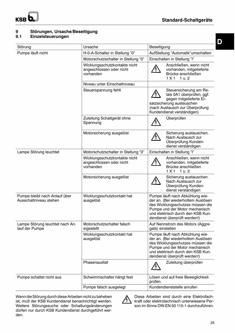
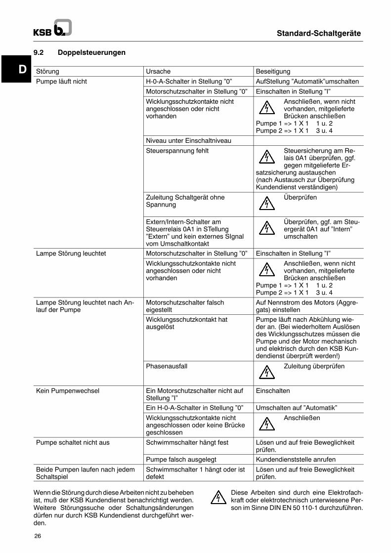
9 Störungen, Ursache/Beseitigung9.1 Einzelsteuerungen
Störung Ursache Beseitigung
Pumpe läuft nicht H-0-A-Schalter in Stellung �0� AufStellung �Automatik�umschalten
Motorschutzschalter in Stellung �0� Einschalten in Stellung �I�
Wicklungsschutzkontakte nichtangeschlossen oder nichtvorhanden
Anschließen, wenn nichtvorhanden, mitgelieferteBrücke anschließen1 X 1 1 u. 2
Niveau unter Einschaltniveau
Steuerspannung fehlt Steuersicherung am Re-lais 0A1 überprüfen, ggf.gegen mitgelieferte Er-
satzsicherung austauschen(nach Austausch zur ÜberprüfungKundendienst verständigen)
Zuleitung Schaltgerät ohneSpannung
Überprüfen
Motorsicherung ausgelöst Sicherung austauschen.Nach Austausch zurÜberprüfung Kunden-dienst verständigen
Lampe Störung leuchtet Motorschutzschalter in Stellung �0� Einschalten in Stellung �I�
Wicklungsschutzkontakte nichtangeschlossen oder nichtvorhanden
Anschließen, wenn nichtvorhanden, mitgelieferteBrücke anschließen1 X 1 1 u. 2
Motorsicherung ausgelöst Sicherung austauschen.Nach Austausch zurÜberprüfung Kunden-dienst verständigen
Pumpe bleibt nach Anlauf überAusschaltniveau stehen
Wicklungsschutzkontakt hatausgelöst
Pumpe läuft nach Abkühlung wie-der an. (Bei wiederholtem Auslösendes Wicklungsschutzes müssen diePumpe und der Motor mechanischund elektrisch durch den KSB Kun-dendienst überprüft werden!)
Lampe Störung leuchtet nach An-lauf der Pumpe
Motorschutzschalter falscheigestellt
Auf Nennstrom des Motors (Aggre-gats) einstellen
Wicklungsschutzkontakt hatausgelöst
Pumpe läuft nach Abkühlung wie-der an. (Bei wiederholtem Auslösendes Wicklungsschutzes müssen diePumpe und der Motor mechanischund elektrisch durch den KSB Kun-dendienst überprüft werden!)
Phasenausfall Zuleitung überprüfen
Pumpe schaltet nicht aus Schwimmschalter hängt fest Lösen und auf freie Beweglichkeitprüfen.
Pumpe falsch ausgelegt Kundendienststelle anrufen
WenndieStörungdurchdieseArbeitennicht zubehebenist, muß der KSB Kundendienst benachrichtigt werden.Weitere Störungssuche oder Schaltungsänderungendürfen nur durch KSB Kundendienst durchgeführt wer-den.
Diese Arbeiten sind durch eine Elektrofach-kraft oder elektrotechnisch unterwiesene Per-son im Sinne DIN EN 50 110-1 durchzuführen.
D
Standard-Schaltgeräte
26
9.2 Doppelsteuerungen
Störung Ursache Beseitigung
Pumpe läuft nicht H-0-A-Schalter in Stellung �0� AufStellung �Automatik�umschalten
Motorschutzschalter in Stellung �0� Einschalten in Stellung �I�
Wicklungsschutzkontakte nichtangeschlossen oder nichtvorhanden
Anschließen, wenn nichtvorhanden, mitgelieferteBrücken anschließen
Pumpe 1 => 1 X 1 1 u. 2Pumpe 2 => 1 X 1 3 u. 4
Niveau unter Einschaltniveau
Steuerspannung fehlt Steuersicherung am Re-lais 0A1 überprüfen, ggf.gegen mitgelieferte Er-
satzsicherung austauschen(nach Austausch zur ÜberprüfungKundendienst verständigen)
Zuleitung Schaltgerät ohneSpannung
Überprüfen
Extern/Intern-Schalter amSteuerrelais 0A1 in STellung�Extern� und kein externes SIgnalvom Umschaltkontakt
Überprüfen, ggf. am Steu-ergerät 0A1 auf �Intern�umschalten
Lampe Störung leuchtet Motorschutzschalter in Stellung �0� Einschalten in Stellung �I�
Wicklungsschutzkontakte nichtangeschlossen oder nichtvorhanden
Anschließen, wenn nichtvorhanden, mitgelieferteBrücken anschließen
Pumpe 1 => 1 X 1 1 u. 2Pumpe 2 => 1 X 1 3 u. 4
Lampe Störung leuchtet nach An-lauf der Pumpe
Motorschutzschalter falscheigestellt
Auf Nennstrom des Motors (Aggre-gats) einstellen
Wicklungsschutzkontakt hatausgelöst
Pumpe läuft nach Abkühlung wie-der an. (Bei wiederholtem Auslösendes Wicklungsschutzes müssen diePumpe und der Motor mechanischund elektrisch durch den KSB Kun-dendienst überprüft werden!)
Phasenausfall Zuleitung überprüfen
Kein Pumpenwechsel Ein Motorschutzschalter nicht aufStellung �I�
Einschalten
Ein H-0-A-Schalter in Stellung �0� Umschalten auf �Automatik�
Wicklungsschutzkontakte nichtangeschlossen oder keine Brückegeschlossen
Anschließen
Pumpe schaltet nicht aus Schwimmschalter hängt fest Lösen und auf freie Beweglichkeitprüfen.
Pumpe falsch ausgelegt Kundendienststelle anrufen
Beide Pumpen laufen nach jedemSchaltspiel
Schwimmschalter 1 hängt oder istdefekt
Lösen und auf freie Beweglichkeitprüfen.
WenndieStörungdurchdieseArbeitennicht zubehebenist, muß der KSB Kundendienst benachrichtigt werden.Weitere Störungssuche oder Schaltungsänderungendürfen nur durch KSB Kundendienst durchgeführt wer-den.
Diese Arbeiten sind durch eine Elektrofach-kraft oder elektrotechnisch unterwiesene Per-son im Sinne DIN EN 50 110-1 durchzuführen.
GB
Standard Switchgears
27
EC declaration of conformity
Herewith we declare that the low-voltage switchgear sets
MSE, EDW, EDC
comply with the following provisions as applicable in their current version:Electromagnetic compatibility directive 89/336/EEC, Annex Iand EC directive on low-voltage equipment 73/23/EEC, Annex II B
Applied harmonized standards, in particular
EN 50 081 part 1/2, EN 50 082 part 1/2, EN 60 439
Hansjörg HeinrichHead of Product DevelopmentBuilding Services Division -- Project Business Section
KSB Aktiengesellschaft, Bahnhofplatz 1, D-91257 Pegnitz
____________________________________________________________________________________________
EC declaration of conformity
Herewith we declare that the low-voltage switchgear sets
DDW, DDC
comply with the following provisions as applicable in their current version:Electromagnetic compatibility directive 89/336/EEC, Annex Iand EC directive on low-voltage equipment 73/23/EEC, Annex II B
Applied harmonized standards, in particular
EN 50 081 part 1/2, EN 50 082 part 1/2, EN 60 439
Hansjörg HeinrichHead of Product DevelopmentBuilding Services Division -- Project Business Section
KSB Aktiengesellschaft, Bahnhofplatz 1, D-91257 Pegnitz
GB
Standard Switchgears
28
EC declaration of conformity
Herewith we declare that the low-voltage switchgear sets
MSD, EDP, ESP, EDH, ESH, EDE, ESE
comply with the following provisions as applicable in their current version:Electromagnetic compatibility directive 89/336/EEC, Annex Iand EC directive on low-voltage equipment 73/23/EEC, Annex II B
Applied harmonized standards, in particular
EN 50 081 part 1/2, EN 50 082 part 1/2, EN 60 439
Hansjörg HeinrichHead of Product DevelopmentBuilding Services Division -- Project Business Section
KSB Aktiengesellschaft, Bahnhofplatz 1, D-91257 Pegnitz
____________________________________________________________________________________________
EC declaration of conformity
Herewith we declare that the low-voltage switchgear sets
DDP, DSP, DDU, DSU, DDH, DSH, DDE, DSE
comply with the following provisions as applicable in their current version:Electromagnetic compatibility directive 89/336/EEC, Annex Iand EC directive on low-voltage equipment 73/23/EEC, Annex II B
Applied harmonized standards, in particular
EN 50 081 part 1/2, EN 50 082 part 1/2, EN 60 439
Hansjörg HeinrichHead of Product DevelopmentBuilding Services Division -- Project Business Section
KSB Aktiengesellschaft, Bahnhofplatz 1, D-91257 Pegnitz
GB
Caution
Standard Switchgears
29
1 GeneralThis KSB unit has been developed in accordance withstate-of-the-art technology; it is manufactured with ut-most care and subject to continuous quality control.These operating instructions are intended to facilitate fa-miliarisation with the unit and its designated use.The manual contains important information for reliable,proper andefficient operation.Compliancewith theoper-ating instructions is of vital importance to ensure reliabil-ity anda long service life of the unit and to avoid any risks.These operating instructions do not take into account lo-cal regulations; the operatormust ensure that such regu-lations are strictly observed by all, including the person-nel called in for installation.This unit must not be operated beyond the limit valuesspecified in the technical documentation for operatingvoltage, rated mains frequency, ambient temperature,switching capacity. Make sure that operation is in accor-dance with the instructions laid down in this manual or inthe contract documentation.The name plate indicates the type series / size, main op-erating data and serial number; please quote this in-formation in all queries, repeat orders and particularlywhen ordering spare parts.If you need any additional information or instructions ex-ceeding the scope of this manual or in case of damageplease contact KSB�s nearest customer service centre.
2 SafetyThese operating instructions contain fundamental in-formation which must be complied with during installa-tion, operation and maintenance. Therefore this operat-ing manual must be read and understood both by theinstalling personnel and the responsible trained person-nel / operators prior to installation and commissioning,and it must always be kept close to the location of opera-tion of the machine / unit for easy access.Not only must the general safety instructions laid downin this chapter on �Safety� be complied with, but also thesafety instructions outlined under specific headings.
2.1 Marking of Instructions in the ManualThe safety instructions contained in this manual whosenon-observance might cause hazards to persons arespecially marked with the general hazard sign, namely
safety sign in accordance with DIN 4844 -- W9.
The electrical danger warning sign is
safety sign in accordance with DIN 4844 -- W8.
The word
isused to introducesafety instructionswhosenon-obser-vance may lead to damage to the unit and its functions.
2.2 Personnel Qualification and TrainingAll personnel involved in the operation, maintenance, in-spection and installation of the unit must be fully qualifiedto carry out the work involved.Personnel responsibilities, competence and supervisionmust be clearly defined by the operator. If the personnelin question is not already in possession of the requisiteknow-how, appropriate training and instruction must beprovided. If required, the operator may commission themanufacturer / supplier to take care of such training. Inaddition, the operator is responsible for ensuring that thecontents of the operating instructions are fully under-stood by the responsible personnel.
2.3 Non-compliance with SafetyInstructions
Non-compliance with safety instructions can jeopardisethe safety of personnel, the environment and the ma-chine itself. Non-compliance with these safety instruc-tions will also lead to forfeiture of any and all rights toclaims for damages.In particular, non-compliance can, for example, result in:-- failure of important unit functions-- failure of prescribed maintenance and servicing prac-tices
-- hazard to persons by electrical, mechanical andchemical effects.
2.4 Safety AwarenessIt is imperative to complywith the safety instructions con-tained in this manual, the relevant national health andsafety regulations and the operator�s own internal work,operation and safety regulations.
2.5 Safety Instructions for the Operator /User
Electrical hazardsmust be eliminated. (In this respect re-fer to the relevant safety regulations applicable to differ-ent countries and/or the local energy supply companies.)
2.6 Safety Instructions for Maintenance,Inspection and Installation Work
The operator is responsible for ensuring that all mainten-ance, inspection and installation work be performed byauthorised, qualified specialist personnel who are thor-oughly familiar with the manual.Work on the unit must be carried out only after the unithas been de-energized.Immediately following completion of the work, all safety-relevant and protective devices must be re-installedand/or re-activated.Please observe all instructions set out in the chapter on�Commissioning� before returning the unit to service.
GB
Standard Switchgears
30
2.7 Unauthorised Modification andManufacture of Spare Parts
Modifications or alterations of the unit are only permittedafter consultation with the manufacturer. Original spareparts and accessories authorised by the manufacturerensure safety. The use of other parts can invalidate anyliability of the manufacturer for consequential damage.
2.8 Unauthorised Modes of OperationThe warranty relating to the operating reliability andsafety of the unit supplied is only valid if the machine isused in accordancewith its designated use as describedin the following sections. The limits stated in the docu-mentation must not be exceeded under any circum-stances.
3 Transport and Interim Storage3.1 TransportTransport of the unit requires proper preparation andhandling. Alwaysmake sure that vertical control cabinetsremain in vertical position during transport, since other-wise, the mounting plate may bend. Prior to dispatch theswitchgear has been checked for compliance with allstated data.On receipt, the unit should therefore be in anelectrically and mechanically perfect condition. Makesure that it has not been damaged during transport. Incase of complaints, a damage report must be written to-gether with the forwarding agent.
3.2 Interim StorageWhen the unit is temporarily put into storage, it should bestored in a dry room not exposed to shocks, if possible inthe original packaging. The ambient temperature mustbe between --10 !C and +50 !C.
4 Description4.1 Technical SpecificationThe descriptions and instructions contained in these op-erating instructions apply to the standard design of origi-nal KSB control units.KSB standard switchgears are low-voltage switchgearsets to EN 60 439 controlling and protecting one or twosingle-phase a.c. motors or three-phase drives. Directstarting of the motor(s) up to 4 kW inclusive (1~ and 3~)and star-delta-starting for 5.5 kW and above (only 3~).
4.2 DesignationStandard switchgearsThe switchgear designation comprises letters and fig-ures (except for MSE/MSD, see description).
E/D D/S P/C/E/W/U/H -/X/L 40 .1
E = single controlD = duplex control
D = direct startingS = star-delta starting
P = volt-free contactsC = capacitor 1)E = explosion-proof 2)W = a.c. currentU = timerHyamation (pressure boosting)
�no letter� (standard)X = special variantL = stagnation pressure measuring(bubbling-through method)
Maximum current intensity x 10
Code
Further codes do not have any influence on the functions de-scribed in the Operating Instructions.Such codes identify, for example, country-specific versionswithregard to the scope of equipmentsuch as the suffix EU(equippedwithmaster switch andcontrol transformer as a stan-dard)or the suffix FLS(control cabinet to be installed outdoors).
1) Motor without running capacitor. Themotor�s capacitor is integratedin the switchgear.
2) Explosion-protection by a special relay. The swichgearmust not beinstalled in potentially explosive atmosphere.
GB
Standard Switchgears
31
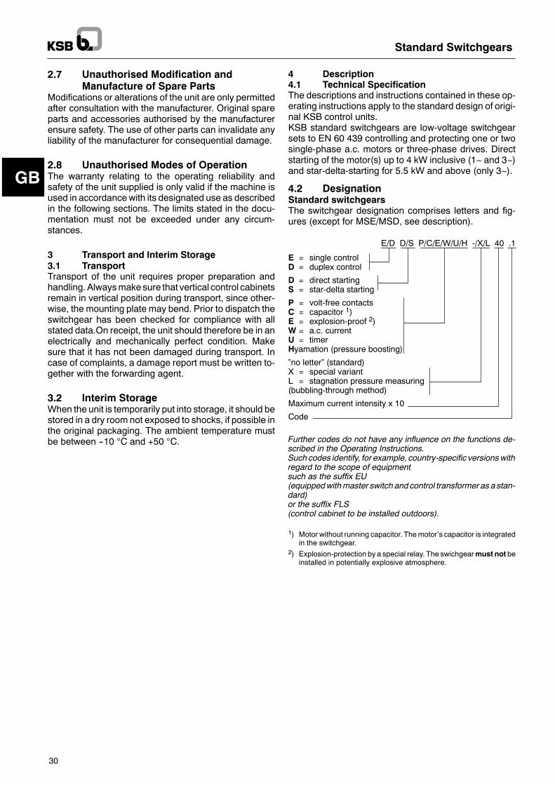
4.3 Design Details (Switchgears) f = option/accessory against extra charge F = standard component4.3.1 MSE/MSD DescriptionMSE/MSD = motor protection relay forsingle-phase motors and three-phase motorsRated operating voltageto IEC 38 MSE 1/N/PE AC 230 V / 50 Hz
MSD 3/N/PE AC 230 / 400 V / 50 HzControl range (up to..)
MSE -1.2 -1.8 -2.6 -3.7 -5.5 -8.0 -11.5 AMSD -0.16 -0.23 -0.36 -0.54 -1.2 -1.8
-2.6 -3.7 -5.5 -8.0 -11.5 ARated insulation voltage AC 690 VType of enclosure IP 54Mains type TN-C-S mainsDimensions HxWxD 170x100x85 mmWeight 1 kg
Integrated componentsF power contactorFmotor protection relayF terminal strip for connection of transmitter, thermalcircuit breaker
MSE / MSD
MSE / MSD
GB
Standard Switchgears
32
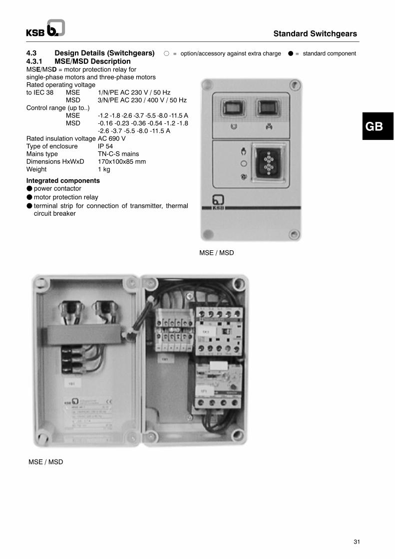
4.3.2 EDW Description f = option/accessory against extra charge F = standard componentRated operating voltageto IEC 38 1/N/PE AC 230 V / 50 HzFuse 10 A, 16 Afuse AC 230 VRated insulation voltage AC 690 VType of enclosure IP 54Mains type TN-C-S mainsDimensions HxWxD 220x270x125 mmWeight 2 kg
Integrated componentsf 1 master switch with emergency switch-off functionF 1 fuseF 1 power contactorF 1 manual-0-automatic switchF 1 relay module for pump controlF 1 indicator lamp for �operation�F 1 indicator lamp for �fault�F terminal strip for connection to themains and connec-tion of the transmitter
F 1 shock-proof socket for motor
GB
Standard Switchgears
33
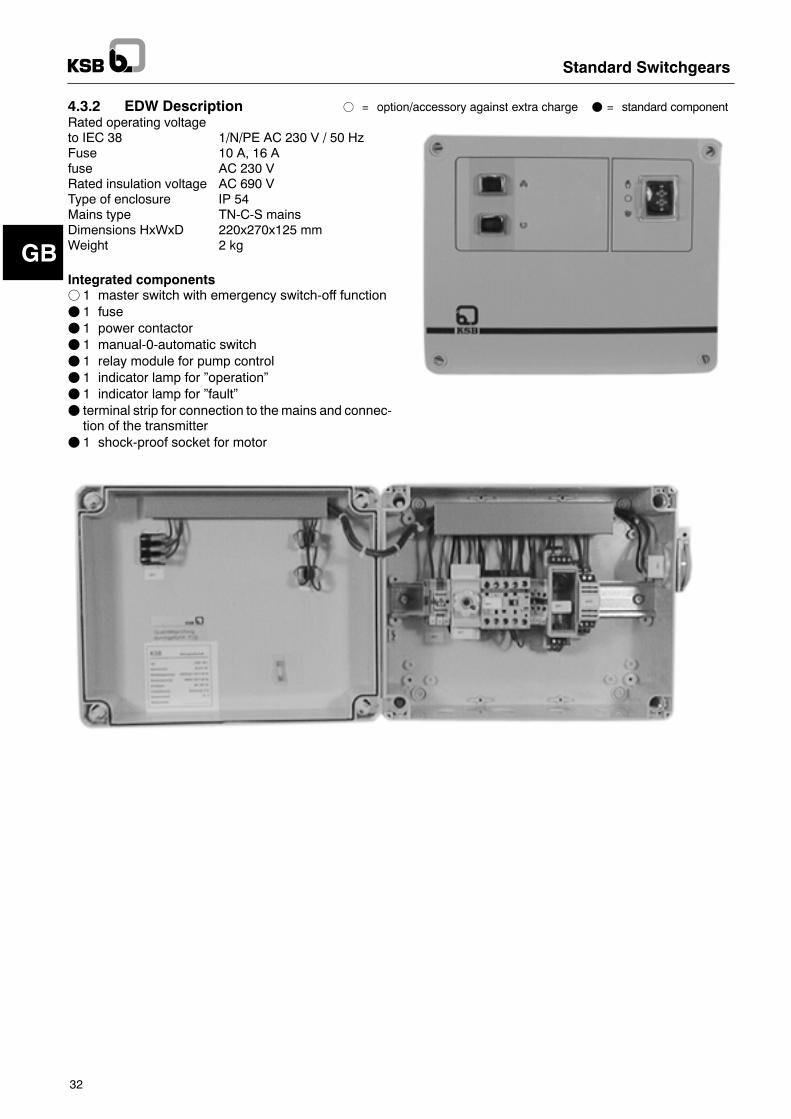
4.3.3 EDC Description f = option/accessory against extra charge F = standard componentRated operating voltageto IEC 38 1/N/PE AC 230 V / 50 HzControl range (up to..) -3.7 -8.0 -14 AControl voltage AC 230 VRated insulation voltage AC 690 VType of enclosure IP 54Mains type TN-C-S mainsDimensions HxWxD 220x270x125 mmWeight 2 kg
Integrated componentsf 1 master switch with emergency switch-off function(standard component for 140.1-40)
F 1 motor protection relay (40.1 and 80.1)F 1 power contactorF 1 motor protection switch (140.1-40)F 1 phase-shifting capacitor 25 mF (40 mF for 140.1-40)F 1 manual-0-automatic switchF 1 relay module for pump controlF 1 indicator lamp for �operation�F 1 indicator lamp for �fault�F terminal strip for connection to themains and connec-tion of motor, phase-shifting capacitor, transmitter,thermal circuit breaker
EDC
EDC 140.1-40
GB
Standard Switchgears
34
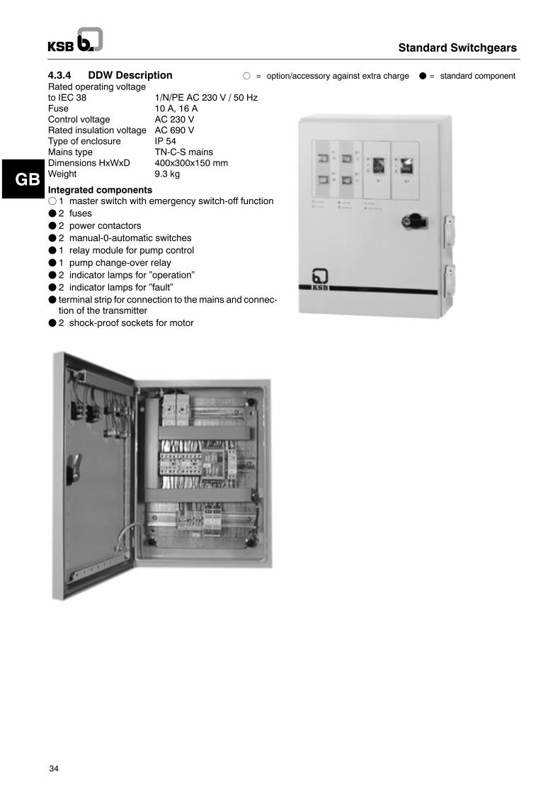
4.3.4 DDW Description f = option/accessory against extra charge F = standard componentRated operating voltageto IEC 38 1/N/PE AC 230 V / 50 HzFuse 10 A, 16 AControl voltage AC 230 VRated insulation voltage AC 690 VType of enclosure IP 54Mains type TN-C-S mainsDimensions HxWxD 400x300x150 mmWeight 9.3 kg
Integrated componentsf 1 master switch with emergency switch-off functionF 2 fusesF 2 power contactorsF 2 manual-0-automatic switchesF 1 relay module for pump controlF 1 pump change-over relayF 2 indicator lamps for �operation�F 2 indicator lamps for �fault�F terminal strip for connection to themains and connec-tion of the transmitter
F 2 shock-proof sockets for motor
GB
Standard Switchgears
35
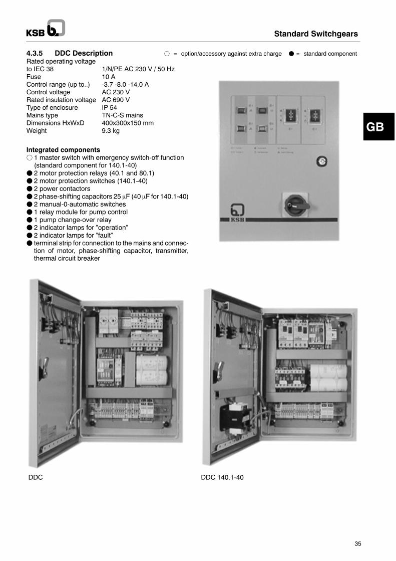
4.3.5 DDC Description f = option/accessory against extra charge F = standard componentRated operating voltageto IEC 38 1/N/PE AC 230 V / 50 HzFuse 10 AControl range (up to..) -3.7 -8.0 -14.0 AControl voltage AC 230 VRated insulation voltage AC 690 VType of enclosure IP 54Mains type TN-C-S mainsDimensions HxWxD 400x300x150 mmWeight 9.3 kg
Integrated componentsf 1 master switch with emergency switch-off function(standard component for 140.1-40)
F 2 motor protection relays (40.1 and 80.1)F 2 motor protection switches (140.1-40)F 2 power contactorsF 2 phase-shifting capacitors 25 mF (40 mF for 140.1-40)F 2 manual-0-automatic switchesF 1 relay module for pump controlF 1 pump change-over relayF 2 indicator lamps for �operation�F 2 indicator lamps for �fault�F terminal strip for connection to themains and connec-tion of motor, phase-shifting capacitor, transmitter,thermal circuit breaker
DDC DDC 140.1-40
GB
Standard Switchgears
36
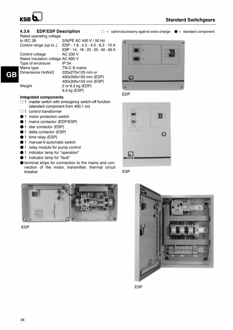
4.3.6 EDP/ESP Description f = option/accessory against extra charge F = standard componentRated operating voltageto IEC 38 3/N/PE AC 400 V / 50 HzControl range (up to..) EDP - 1.6 - 2.5 - 4.0 - 6.3 - 10 A
ESP - 14 - 18 - 23 - 25 - 40 - 63 AControl voltage AC 230 VRated insulation voltage AC 690 VType of enclosure IP 54Mains type TN-C-S mainsDimensions HxWxD 220x270x125 mm or
400x300x150 mm (EDP)400x300x150 mm (ESP)
Weight 2 or 9.3 kg (EDP)9.3 kg (ESP)
Integrated componentsf 1 master switch with emergency switch-off function
(standard component from 400.1 on)f 1 control transformerF 1 motor protection switchF 1 mains contactor (EDP/ESP)F 1 star contactor (ESP)F 1 delta contactor (ESP)F 1 time relay (ESP)F 1 manual-0-automatic switchF 1 relay module for pump controlF 1 indicator lamp for �operation�F 1 indicator lamp for �fault�F terminal strips for connection to the mains and con-nection of the motor, transmitter, thermal circuitbreaker
EDP
ESP
EDP
ESP
GB
Standard Switchgears
37
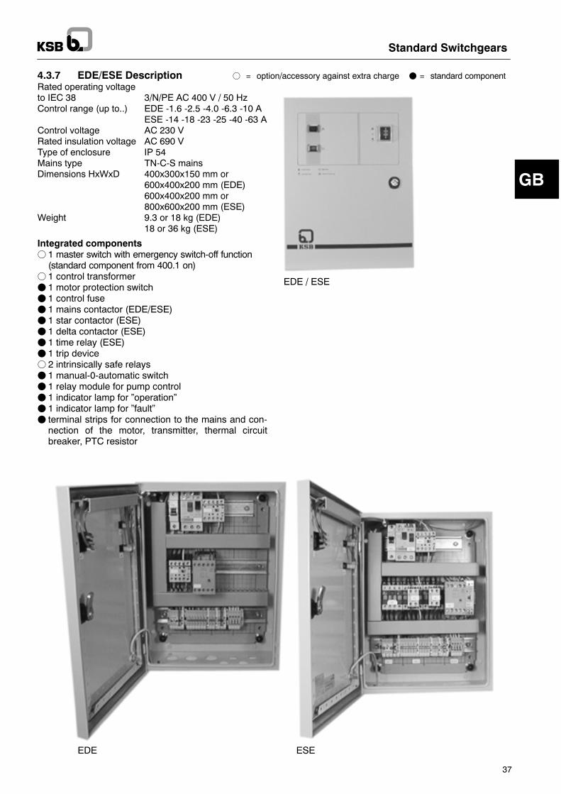
4.3.7 EDE/ESE Description f = option/accessory against extra charge F = standard componentRated operating voltageto IEC 38 3/N/PE AC 400 V / 50 HzControl range (up to..) EDE -1.6 -2.5 -4.0 -6.3 -10 A
ESE -14 -18 -23 -25 -40 -63 AControl voltage AC 230 VRated insulation voltage AC 690 VType of enclosure IP 54Mains type TN-C-S mainsDimensions HxWxD 400x300x150 mm or
600x400x200 mm (EDE)600x400x200 mm or800x600x200 mm (ESE)
Weight 9.3 or 18 kg (EDE)18 or 36 kg (ESE)
Integrated componentsf 1 master switch with emergency switch-off function(standard component from 400.1 on)
f 1 control transformerF 1 motor protection switchF 1 control fuseF 1 mains contactor (EDE/ESE)F 1 star contactor (ESE)F 1 delta contactor (ESE)F 1 time relay (ESE)F 1 trip devicef 2 intrinsically safe relaysF 1 manual-0-automatic switchF 1 relay module for pump controlF 1 indicator lamp for �operation�F 1 indicator lamp for �fault�F terminal strips for connection to the mains and con-nection of the motor, transmitter, thermal circuitbreaker, PTC resistor
EDE / ESE
ESEEDE
GB
Standard Switchgears
38
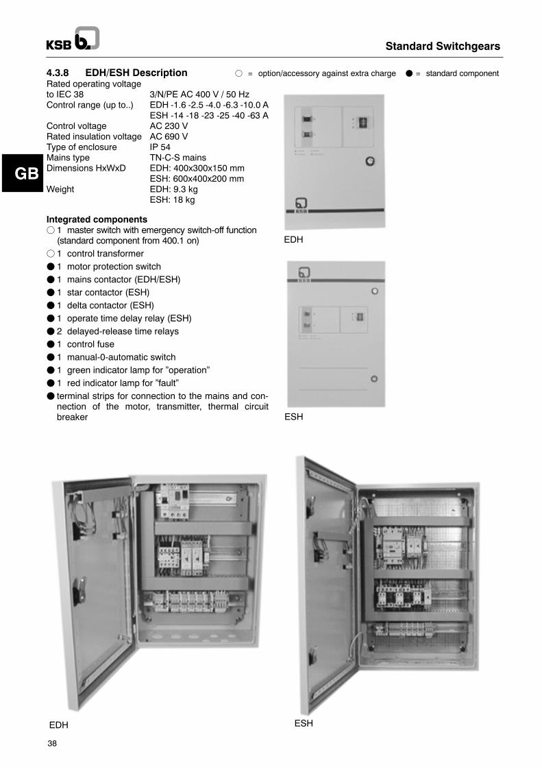
4.3.8 EDH/ESH Description f = option/accessory against extra charge F = standard componentRated operating voltageto IEC 38 3/N/PE AC 400 V / 50 HzControl range (up to..) EDH -1.6 -2.5 -4.0 -6.3 -10.0 A
ESH -14 -18 -23 -25 -40 -63 AControl voltage AC 230 VRated insulation voltage AC 690 VType of enclosure IP 54Mains type TN-C-S mainsDimensions HxWxD EDH: 400x300x150 mm
ESH: 600x400x200 mmWeight EDH: 9.3 kg
ESH: 18 kg
Integrated componentsf 1 master switch with emergency switch-off function(standard component from 400.1 on)
f 1 control transformerF 1 motor protection switchF 1 mains contactor (EDH/ESH)F 1 star contactor (ESH)F 1 delta contactor (ESH)F 1 operate time delay relay (ESH)F 2 delayed-release time relaysF 1 control fuseF 1 manual-0-automatic switchF 1 green indicator lamp for �operation�F 1 red indicator lamp for �fault�F terminal strips for connection to the mains and con-nection of the motor, transmitter, thermal circuitbreaker
EDH
ESH
EDH ESH
GB
Standard Switchgears
39
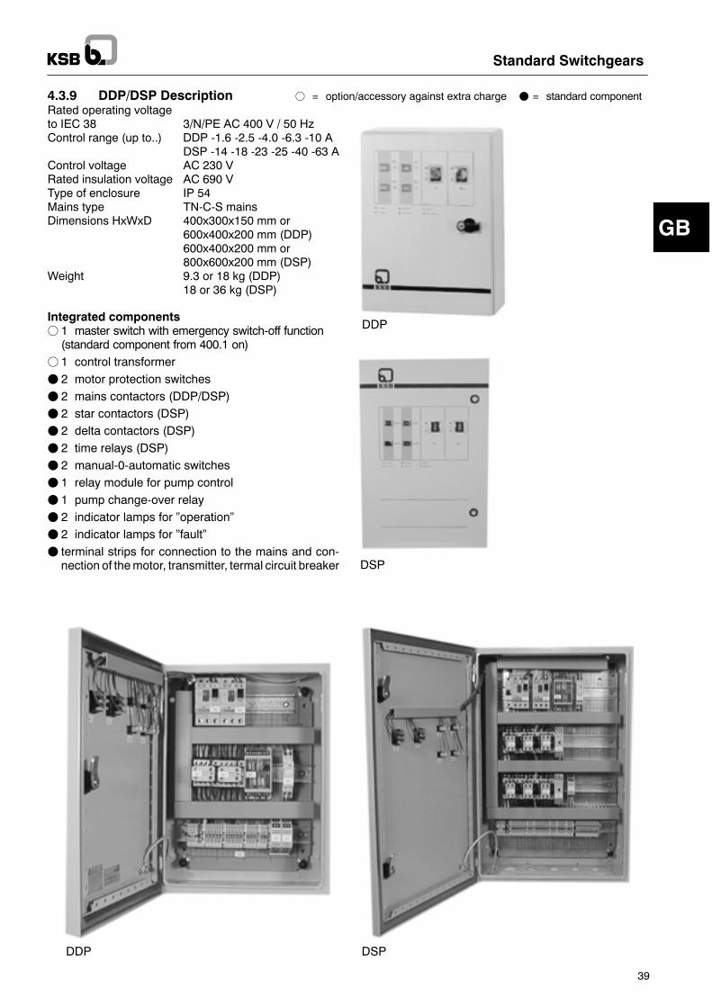
4.3.9 DDP/DSP Description f = option/accessory against extra charge F = standard componentRated operating voltageto IEC 38 3/N/PE AC 400 V / 50 HzControl range (up to..) DDP -1.6 -2.5 -4.0 -6.3 -10 A
DSP -14 -18 -23 -25 -40 -63 AControl voltage AC 230 VRated insulation voltage AC 690 VType of enclosure IP 54Mains type TN-C-S mainsDimensions HxWxD 400x300x150 mm or
600x400x200 mm (DDP)600x400x200 mm or800x600x200 mm (DSP)
Weight 9.3 or 18 kg (DDP)18 or 36 kg (DSP)
Integrated componentsf 1 master switch with emergency switch-off function(standard component from 400.1 on)
f 1 control transformerF 2 motor protection switchesF 2 mains contactors (DDP/DSP)F 2 star contactors (DSP)F 2 delta contactors (DSP)F 2 time relays (DSP)F 2 manual-0-automatic switchesF 1 relay module for pump controlF 1 pump change-over relayF 2 indicator lamps for �operation�F 2 indicator lamps for �fault�F terminal strips for connection to the mains and con-nection of themotor, transmitter, termal circuit breaker
DDP
DSP
DDP DSP
GB
Standard Switchgears
40
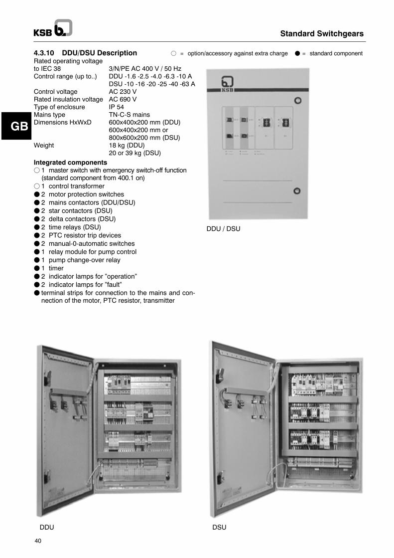
4.3.10 DDU/DSU Description f = option/accessory against extra charge F = standard componentRated operating voltageto IEC 38 3/N/PE AC 400 V / 50 HzControl range (up to..) DDU -1.6 -2.5 -4.0 -6.3 -10 A
DSU -10 -16 -20 -25 -40 -63 AControl voltage AC 230 VRated insulation voltage AC 690 VType of enclosure IP 54Mains type TN-C-S mainsDimensions HxWxD 600x400x200 mm (DDU)
600x400x200 mm or800x600x200 mm (DSU)
Weight 18 kg (DDU)20 or 39 kg (DSU)
Integrated componentsf 1 master switch with emergency switch-off function(standard component from 400.1 on)
f 1 control transformerF 2 motor protection switchesF 2 mains contactors (DDU/DSU)F 2 star contactors (DSU)F 2 delta contactors (DSU)F 2 time relays (DSU)F 2 PTC resistor trip devicesF 2 manual-0-automatic switchesF 1 relay module for pump controlF 1 pump change-over relayF 1 timerF 2 indicator lamps for �operation�F 2 indicator lamps for �fault�F terminal strips for connection to the mains and con-nection of the motor, PTC resistor, transmitter
DDU / DSU
fehltDDU folgt neuvon BOE
DDU DSU
GB
Standard Switchgears
41
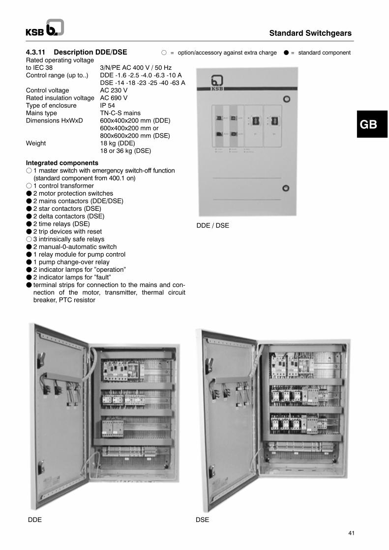
4.3.11 Description DDE/DSE f = option/accessory against extra charge F = standard componentRated operating voltageto IEC 38 3/N/PE AC 400 V / 50 HzControl range (up to..) DDE -1.6 -2.5 -4.0 -6.3 -10 A
DSE -14 -18 -23 -25 -40 -63 AControl voltage AC 230 VRated insulation voltage AC 690 VType of enclosure IP 54Mains type TN-C-S mainsDimensions HxWxD 600x400x200 mm (DDE)
600x400x200 mm or800x600x200 mm (DSE)
Weight 18 kg (DDE)18 or 36 kg (DSE)
Integrated componentsf 1 master switch with emergency switch-off function(standard component from 400.1 on)
f 1 control transformerF 2 motor protection switchesF 2 mains contactors (DDE/DSE)F 2 star contactors (DSE)F 2 delta contactors (DSE)F 2 time relays (DSE)F 2 trip devices with resetf 3 intrinsically safe relaysF 2 manual-0-automatic switchF 1 relay module for pump controlF 1 pump change-over relayF 2 indicator lamps for �operation�F 2 indicator lamps for �fault�F terminal strips for connection to the mains and con-nection of the motor, transmitter, thermal circuitbreaker, PTC resistor
DDE / DSE
DDE DSE
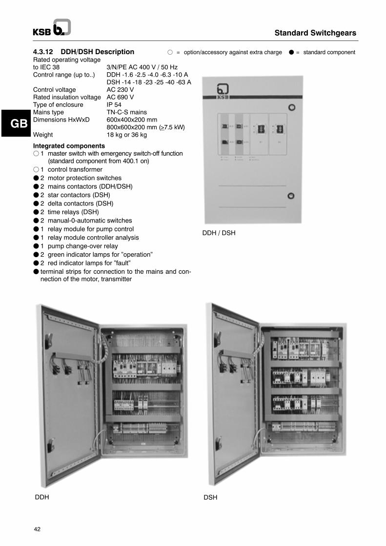
GB
Standard Switchgears
42
4.3.12 DDH/DSH Description f = option/accessory against extra charge F = standard componentRated operating voltageto IEC 38 3/N/PE AC 400 V / 50 HzControl range (up to..) DDH -1.6 -2.5 -4.0 -6.3 -10 A
DSH -14 -18 -23 -25 -40 -63 AControl voltage AC 230 VRated insulation voltage AC 690 VType of enclosure IP 54Mains type TN-C-S mainsDimensions HxWxD 600x400x200 mm
800x600x200 mm (>7.5 kW)Weight 18 kg or 36 kg
Integrated componentsf 1 master switch with emergency switch-off function
(standard component from 400.1 on)f 1 control transformerF 2 motor protection switchesF 2 mains contactors (DDH/DSH)F 2 star contactors (DSH)F 2 delta contactors (DSH)F 2 time relays (DSH)F 2 manual-0-automatic switchesF 1 relay module for pump controlF 1 relay module controller analysisF 1 pump change-over relayF 2 green indicator lamps for �operation�F 2 red indicator lamps for �fault�F terminal strips for connection to the mains and con-nection of the motor, transmitter
DDH / DSH
DDH DSH
Caution
Standard Switchgears
43
4.4 Options-- Operating hours counter-- Ammeter-- Master switch (standard component from 400.1 and630.1 on)
-- Voltmeter-- PTC resistor connection with trip device (standardcomponent from 400.1 on and DDU/DSU)
-- Monitoring relay (phase sequence/phase failure,overvoltage/undervoltage)
-- Further options upon request
5 Installation at Site5.1 Ambient Conditions-- Dry and frostproof-- Adequately ventilated-- Lockable. No possibility of access by unauthorisedpersons
The switchgear set installations must be floodsafe.The switchgears are not explosion-proof. Therefore,they must not be operated in hazardous locations.
5.2 Connection to the Power SupplyFConnection to the power supply must be effected by atrained electrician only.
FConnection to the power supply must be effected in ac-cordancewith the technical regulations of the responsiblelocal energy supply company.
FCheck the current type and the voltage of the mains.F Themotor must be connected in accordance with the cir-cuit diagram.
F Set the motor protection switch to the rated current.F Power supply cable dimensioned in accordancewith DINVDE 0100, part 430.
FMax. external fusing acc. to the circuit diagram.In case of three-phase motors, the power supply cableprovided at site must be connected as rotating field turn-ing to the right. In case of single-phase a.c. motors, thephase and the neutral line must be correctly connected.Connect only KSB pumps whose technical datacomply with those of this switchgear set.Other machines must not be connected as this willcause damage to the switchgear set.Effect the connection according to the circuit diagram.F Float switch as per circuit diagram specifications.F The thermal circuit breakermust be connected to the cor-responding cores of the pump cable.
If the pumps are not equipped with thermal circuit break-ers the switchgear set must be fitted with a bridge.
6 Commissioning, Start-up/Shutdown6.1 GeneralCommissioning, start-up shall never be effected until ithas been ensured that all pertinent VDE provisions arecomplied with.Always check the following points prior to commission-ing/start-up of the switchgear set:-- pump cable connected,
-- thermal circuit breaker connected,-- power supply cable properly connected (field rotatingto the right in case of three-phase drives),
-- transmitters (float switch, pressure switch, timer) con-nected and properly set. Please refer to sections 6.2.1to 6.2.4.
Not until all of the above points have been duly executedby a trained electrician shall the start-up procedure forthe switchgear set be commenced with.In performing such work, adherence to the cable-connection sectionof thecircuit diagramand theop-erating instructions for the pump is mandatory.
6.2 Commissioning/Start-up
Prior to commissioning/start-up the following work mustbe carried out. It is mandatory to follow the instructionsof sections 6.2.1 to 6.2.4.-- Set the master switch to �0�.-- Set the manual-0-automatic switch to �0�.-- Compare the setting of the motor protection switchwith thre motor�s rated current and adjust as neces-sary.
-- Set the motor protection switch to �I�.-- The time relay for change from star to delta has beenpreset at the factory to 3 seconds and must be ad-justed if required.
-- Enable power supply. To this effect, set plant-side fuse(i.e. automatic fuse) to �On�.
-- If a master switch is fitted, set it to �I�.-- Check the direction of rotation of three-phasemotors .To this effect, set the manual-0-automatic switch for ashort time to �manual� -- only above the switch-off levelor below switch-off pressure.
-- Observe the relevant pump operating instructions.
6.2.1 Single and Duplex Control Units--Level-dependent
Thepump(s) is (are) switchedonandoff bymeans of one(two) float switch(es), level transmitter(s) or magneticswitch(es).The switching level must be set at site.The switching level is set by fixing the float switch cableon the discharge pipe, the handle or other suitable pointsat an appropriate height and by selecting an appropriatefree float switch cable length. It should not be shorterthan 100 mm measured from the antikink bush in orderto ensure correct switching even with a cold, stiff cable.The unit is switched on at an upper slant of the float hous-ing of approx. 30! and switched off at a lower slant of thefloat housing of 30! (clearly audible switchingnoise in thefloat housing). The minimum switching difference isapprox. 400 mm. When setting the switching points seeto it that the pump switches off before the water levelreaches the suction openings of the foot. Start-up mustbe effected before the water level reaches the uppersumpedge. The float switchmust neither come to rest onthe bottom nor bump against the sump cover, if installed.Makesure that the float cannot get caught onanyproject-ing parts, juts or similar in the sump.
GB
Standard Switchgears
44
In the case of two pumps and use of a duplex control unit,the two float switches must be arranged in cascade. Thefollowing 3 switching functions are possible:1. Alternating start-up of both pumps in each switchingcycle.
2. Additional starting of the second pump in case of peakload.
3. Additional starting of the second pump in case of fail-ure/fault.
6.2.2 Single Control Unit --Pressure-dependent
The pump is switched on and off by means of a pressureswitch fitted in the discharge pipe. The pressure switchquality and design must be compatible with the media tobe handled.The pressure switch is set in accordance with the rele-vant instructions. The time relay connected to the pres-sure switch (see circuit diagram) avoids an excessiveswitching frequency if it is correctly set and adjusted tothe hydraulics. Thus, in the case of extremely low con-sumption, permanent switching on and off is avoided.The time relay is set at site.An inlet side float switch, pressure switch or electrodes(option) prevent dry running of the pump.A time relay or an electrode relay avoids an excessiveswitching frequency (fluttering) if the water level or pres-sure is not reached for a short time. Each time delaymustbe adjusted to the plant.The float switch must be fitted in such a way that it canmove freely and the pump will be switched off in case ofaminimumwater level. The float conemust never cometo rest on the bottom or bump against the sump cover.The electrodes must be fitted in the tank as follows:Connect the electrode to the electrode cable in accor-dance with the instructions. Lower the earth electrodeuntil it comes to rest on the tank bottom . It must be justable to swing freely.Now the second electrode is suspended; the distancebetween the electrode�s lower edge and the bottom de-pends on the minimum permissible water level.The pressure switch is set to the mimimum permissibleinlet pressure in accordance with the relevant instruc-tions.
6.2.3 Duplex Control Unit -- Time-dependentTheduplex control unit has different functions that canbeactivated externally via volt-free contacts.-- External release -- remove the bridge as indicated inthe circuit diagram and connect the volt-free contact.
-- External peak load -- via a volt-free contact.-- External pump change-over -- set the switch on thepump control relay from �Internal� to External�. Con-nect volt-free change-over contact without OFF-posi-tion in accordance with the circuit diagram. Now thepump change-over is activated via this contact.
The switching contacts for the different exter-nal functions must be designed for 230 V/50 Hz, 1 Aind minimum.
The integrated timer allows for internal activation of thepump change-over. After having enabled the power sup-ply, the timer must be programmed. At first, the currenttime and the day of theweekmust be programmed. Thenthe change-over times can be programmed. The stepsare described in the timer�s operating instructions; theydiffer from make to make.
6.2.4 Duplex Control Unit --Pressure-dependent
The pumps are switched on and off by means of a three-step controller fitted in thedischargepipe. The three-stepcontroller�s quality and design must be compatible withthe media to be handled.The controllermust be set in accordancewith the instruc-tions supplied with it.The time relays �after-run time� and �peak load� (see cir-cuit diagram) are preset at the factory and prevent an ex-cessive switching frequency (fluttering).In case of unfavourable plant conditions itmay be neces-sary to modify this pre-setting. Please record the newsetting in the circuit diagram.An inlet side float switch, pressure switch or electrodes(option) prevent dry running of the pump.A time relay or an electrode relay avoids an excessiveswitching frequency (fluttering) if the water level or pres-sure is not reached for a short time. Each time delaymustbe adjusted to the plant.The float switch must be fitted in such a way that it canmove freely and the pump will be switched off in case ofaminimumwater level. The float conemust never cometo rest on the bottom or bump against the sump cover.The electrodes must be fitted in the tank as follows:Connect the electrode to the electrode cable in accor-dance with the instructions. Lower the earth electrodeuntil it comes to rest on the tank bottom . It must be justable to swing freely.Now the second electrode is suspended; the distancebetween the electrode�s lower edge and the bottom de-pends on the minimum permissible water level.The pressure switch is set to the mimimum permissibleinlet pressure in accordance with the relevant instruc-tions.
GB
Standard Switchgears
45
6.3 Functional Description ofSingle Control Unit
6.3.1 Automatic Operation -- Level ControlThe motor is switched on and off via a three-positionswitch (manual-0-automatic).�0� position: The motor is switched off.�Automatic� position: Themotor is switchedonandoff viaan external transmitter.�Manual� position: If the switch is set to �manual�, themo-tor can be switched on manually.Draining a tank/pit; float switch transmitter circuit closedwhen switch is in upper position.The pump is switched on and off depending on the liquidlevel. As soon as the level of the medium handledreaches the point of activating the float switch, the pumpis started up. The medium handled is then pumped untilthe switch-off level of the float switch is reached.With theswitch set to �manual� thepumpcanbeswitchedon directly. However, such operation should be limited tocases in which the medium handled is above theswitch-off level, and then only for a short time, e.g. forchecking the direction of rotation.Otherwise, the switch should always be set to �auto-matic�.
6.3.2 Automatic Operation --Pressure-dependent Control
The motor is switched on and off via a three-positionswitch (manual-0-automatic).�0� position: The motor is switched off.�Automatic� position: Themotor is switchedonandoff viaan external transmitter.�Manual� position: If the switch is set to �manual�, themo-tor can be switched on manually.The pump is switched on depending on the pressure ifthe system pressure is inferior to the value set on thepressure switch. The time relay ensures a minimum op-erating period. The time relay can be set to comply withthe system conditions. The pump is switched off withdelay after the switch-off pressure set on the pressureswitch has been reached.A pressure switch fitted in the inlet pipemonitors the inletpressure.Acorresponding time relaywhichcanbeset in-dividually avoidsanexcessiveswitching frequencywhenthe system is started up and the pressure drops for ashort period. The system is switched off via the pressurecontrol device if the minimum inlet pressure in the con-nection pipe is not reached within the set time period.The (red) indicator lamp for lack of water indicates thatthe water quantity or inlet pressure in the inlet pipe is notsufficient. The pump is switched on again automaticallyif the minimum inlet pressure is reached again.The (red) indicator lamp for �fault� indicates that the mo-tor protection switch has tripped the pump. If the auto-matic system fails completely, the pump can be switchedon manually. To do so, set the manual-0-automaticswitch to �manual�.
6.4 Functional Description ofDuplex Control Unit
6.4.1 Automatic Operation -- Level ControlThe motor is switched on and off via a three-positionswitch (manual-0-automatic).�0� position: The motor is switched off.�Automatic� position: Themotor is switchedonandoff viaan external transmitter. If both switches are set to �auto-matic� the motors are switched on and off alternately af-ter eachswitchingcycle. In thecaseof amotor failure, thesecond motor starts up immediately.�Manual� position: If the switch is set to �manual�, themo-tor can be switched on manually.Draining a tank/pit; float switch transmitter circuit closedwhen switch is in upper position.The pumps are switched on and off alternately depend-ing on the liquid level. In case of need, the peak loadpump is connected automatically. As soon as the level ofthe medium handled drops to the point of activating floatswitch 1 (bottom level), one pump is started up. The me-dium handled is then pumped until the switch-off level offloat switch 1 is reached.As more medium enters the tank, the start-up level offloat switch 1 is eventually reached again, at which pointthe second pump is started up until the medium drops tothe switch-off level. This switching cycle is repeated aftereach switch-off.Should the medium handled rise to the level of floatswitch 2 (top level) despite pump operation, pump 2 isalso started up (peak load operation).In the case of a pump failure due to tripping of the thermalcircuit breaker, thePTC resistor or of themotor protectionswitch the second pump starts up immediately (stand-byoperation).With the switch set to �manual� each pump can beswitched on directly. However, such operation should belimited to cases in which the medium handled is abovethe switch-off level, and then only for a short time, e.g. forchecking the direction of rotation.Otherwise, the switch should always be set to �auto-matic�.
GB
Standard Switchgears
46
6.4.2 Automatic Operation --Time-dependent Control
The motor is switched on and off via a three-positionswitch (manual-0-automatic). For each motor there isone switch.�0� position: The motor is switched off.�Automatic� position: If both switches are set to �auto-
matic� the integrated timerswitches themotors on and off al-ternately depending on the time.In the case of a motor failure, thesecond motor starts up immedi-ately.
�Manual� position: If the switch is set to �manual�, themotor can be switched on ma-nually.
If the manual-0-automatic switches are set to �auto-matic�, the pumps will be changed depending on thechange-over time programmed in the digital timer. Thischange-over from pump 1 to pump 2 can be triggered byan external contact, if fitted. This, however, is only pos-sible if the lateral change-over switch on the control unitis set to �external�.In case of need, the second pump can be connected au-tomatically via the external peak load contact. If the ex-ternal release contact is interrrupted, the pumps cannotbe started up, neither in manual operation nor in auto-matic operation.If a pump fails during operation, the second pump isstarted up automatically.With the switch set to �manual�, each pump can beswitched on directly. Such operation is necessary if thedirection of rotation must be checked, for example. If bothmanual-0-automatic switches are set to �manual�, a peak-load connection can be triggered by an internal signal.Otherwise, the switches should always be set to �auto-matic� for start-up.
6.4.3 Automatic Operation --Pressure-dependent Control
The motor is switched on and off via a three-positionswitch (manual-0-automatic). For each motor there isone switch.�0� position: The motor is switched off.�Automatic� position: The motor is switched on and off
via an external transmitter. If bothswitches are set to �automatic�the motors are switched on andoff alternately after each switch-ing cycle. In the case of a motorfailure, the second motor startsup immediately.
�Manual� position: If the switch is set to �manual�, themotor can be switched on manu-ally.
Thesystem is switchedonandoff dependingon thepres-sure.The switching impulse is given to the control unit by a three-step controller fitted in the discharge pipe. The control unitthen switches the pumps on and off depending on the wa-ter requirement and ensures that the system pressure re-mains constant between two pressure limits to be set.
The pumps are switched on alternately to ensure anequal distributionof pumpoperatinghours. If a pump failsduring operation, the second pump is started up auto-matically (stand-by) unless peak load operation hasbeen selected. If the set pressure is not reached withina set period of time although a pump is in operation, thesecond pump is started up automatically.If the system pressure has reached the set switch-offpressure, an after-run time commenceswhich can be setindividually. The pump(s) is (are) only switched off if dur-ing theentire after-run time thesystempressureexceedsthe switch-off pressure. If the system pressure drops fora short time and increases again, the after-run time com-mences again. This way the switching frequency of thepumps is reduced in case of low flow rates.In order to protect the pumps against dry running and/oragainst insufficient inlet pressure an inlet side pressureswitch can be fitted. An intermediate time relay analysesthis signal. The pumps are switched off if for the periodof time set on the relay (adjusted to the system) the inletpressure drops below the minimum pressure set on thepressure switch.In the case of a failure of the three-step controller, pump1and/or 2 can be put into continuous operation. To do so,set the manual-0-automatic switch to �manual�. Unre-stricted system operation is thus ensured.
Ensure minimum flow.
6.5 Manual OperationThe �manual� operating mode ensures for all single andduplex control units that the pump(s) can be switched onand off manually after failure of the control unit.However, suchoperation should be limited to emergencycases (for example highwater, fire-fightingwater) or dur-ing start-up (for example for checking the direction ofrotation).In drainage systems the pump(s) may only be switchedon with the switch set to �manual� if the medium handledis above the system switch-off level and in pressure-boosting units if themediumhandled is below the systemswitch-off pressure. Make sure that no personal injury ordamage to property will occur.
GB
Standard Switchgears
47
6.6 Shutdown-- Set the manual-0-automatic switch to �0�.If a master switch is fitted, set it to �0�.
-- Before opening the switch box and the motor terminalbox interrupt the power supply to the system.
-- Set the motor protection switch to �0�.-- Before carrying out work on the control cabinet pleasecheck with a voltmeter whether all phases are actuallydead.
7 Returning to Service(see Commissioning/Start-up)
-- Set the manual-0-automatic switch to �0�.-- Compare the motor protection switch setting with themotor�s rated current and adjust as necessary.
-- Enable power supply.-- Check the direction of rotation. To do so, set themanual-0-automatic switch to �manual� for a shorttime only if the medium handled is above the start-uplevel.Adherence to the pump operating instructions is man-datory.
8 MaintenanceWe recommend an annual switchgear check.
GB
Standard Switchgears
48
9 Faults, Cause/Remedy9.1 Single Control Units
Fault Cause Remedy
Pump not running Manual-0-automatic switch set to �0� Set to �automatic�
Motor protection switch set to �0� Set to �I� for starting
Thermal circuit breakers not fittedor disconnected
Connect; if not fitted, con-nect companion bridge1 X 1 1 and 2
Liquid level below start-up level
No control voltage Check control fuse onrelay 0A1; replace as ne-cessary with supplied
spare fuse (then call your KSB ser-vice centre)
No power to switchgear powersupply cable
Inspect
Motor fuse tripped Replace fuse; then callyour KSB service centre.
Fault lamp lit Motor protection switch set to �0� Set to �I� for starting
Thermal circuit breakers not fittedor disconnected
Connect; if not fitted, con-nect companion bridge1 X 1 1 and 2
Motor fuse tripped Replace fuse; then callyour KSB service centre
Pump is switched off after start-up,the liquid level being above theswitch-off level
Thermal circuit breaker tripped Pump starts up again after coolingdown (should the thermal circuitbreaker trip repeatedly, have thepump and the motor checked byyour KSB service center)
Fault lamp lights up after pumpstart-up
Motor protection switch set wrong Set to rated motor current (unit)
Thermal circuit breaker tripped Pump starts up again after coolingdown (should the thermal circuitbreaker trip repeatedly, have thepump and the motor checked byyour KSB service centre)
Phase failure Check power supply cable
Pump is not switched off Float switch jammed Free and check that it can movefreely.
Wrong pump selected Call KSB service centre
Should it prove impossible to remedy the fault by theabovemeasures, a KSBservice engineermust be calledin for any additional trouble-shooting and/or modificationof circuitry.
All such work must be performed by either atrained electrician or another appropriatelytrained person as defined by DIN EN 50 110-1.
GB
Standard Switchgears
49
9.2 Duplex Control Units
Fault Cause Remedy
Pump not running Manual-0-automatic switch set to �0� Set to �automatic�
Motor protection switch set to �0� Set to �I� for starting
Thermal circuit breakers not fittedor disconnected
Connect; if not fitted,connect companionbridges
Pump 1 => 1 X 1 1 and 2Pump 2 => 1 X 1 3 and 4
Liquid level below start-up level
No control voltage Check control fuse onrelay 0A1; replace as nec-essary with supplied
spare fuse (then call your KSB ser-vice center)
No power to switchgear powersupply cable
Inspect
External/internal switch on thecontrol relay 0A1 set to �external�and no external signal from thechange-over contact
Check, if necessary set toto �internal� on control unit0A1
Fault lamp lit Motor protection switch set to �0� Set to �I� for starting
Thermal circuit breakers not fittedor disconnected
Connect; if not existing,connection companionbridges
Pump 1 => 1 X 1 1 and 2Pump 2 => 1 X 1 3 and 4
Fault lamp lights up after pumpstart-up
Motor protection switch set wrong Set to rated motor (unit) current
Thermal circuit breaker tripped Pump starts up again after coolingdown (should the thermal circuitbreaker trip repeatedly, have thepump and the motor checked byyour KSB service centre)
Phase failure Check power supply cable
No pump change-over One motor protection switch not setto �I�
Switch on
One manual-0-automatic switch setto �0�
Set to �automatic�
Thermal circuit breakers notconnected or no bridge
Connect
Pump is not switched off Float switch jammed Free and check that it can movefreely.
Wrong pump selected Call KSB service centre
Both pumps are running after eachswitching cycle
Float switch 1 jammed or defective Free and check that it can movefreely.
Should it prove impossible to remedy the fault by theabovemeasures, a KSBservice engineermust be calledin for any additional trouble-shooting and/or modificationof circuitry.
All such work must be performed by either atrained electrician or another appropriatelytrained person as defined by DIN EN 50 110-1.
F
Dispositifs de commande standard
50
Déclaration de conformité
Par la présente, nous déclarons que les dispositifs de commande basse tension
MSE, EDW, EDC
correspondent aux dispositions pertinentes suivantes dans la version respective en vigueur :Directive �CE� relative à la compatibilité électromagnétique 89/336/CEE, Annexe IDirective �CE� relative à la basse tension 73/23/CEE, annexe III B
Normes harmonisées utilisées, notamment
EN 50 081 parties 1/2, EN 50 082 parties 1/2, EN 60 439
Hansjörg HeinrichLe responsable Développement ProduitsDivision Pompes pour le bâtiment -- Secteur Projet
KSB Aktiengesellschaft, Bahnhofplatz 1, D-91257 Pegnitz
____________________________________________________________________________________________
Déclaration de conformité
Par la présente, nous déclarons que les dispositifs de commande basse tension
DDW, DDC
correspondent aux dispositions pertinentes suivantes dans la version respective en vigueur :Directive �CE� relative à la compatibilité électromagnétique 89/336/CEE, Annexe IDirective �CE� relative à la basse tension 73/23/CEE, annexe III B
Normes harmonisées utilisées, notamment
EN 50 081 parties 1/2, EN 50 082 parties 1/2, EN 60 439
Hansjörg HeinrichLe responsable Développement ProduitsDivision Pompes pour le bâtiment -- Secteur Projet
KSB Aktiengesellschaft, Bahnhofplatz 1, D-91257 Pegnitz
F
Dispositifs de commande standard
51
Déclaration de conformité
Par la présente, nous déclarons que les dispositifs de commande basse tension
MSD, EDP, ESP, EDH, ESH, EDE, ESE
correspondent aux dispositions pertinentes suivantes dans la version respective en vigueur :Directive �CE� relative à la compatibilité électromagnétique 89/336/CEE, Annexe IDirective �CE� relative à la basse tension 73/23/CEE, annexe III B
Normes harmonisées utilisées, notamment
EN 50 081 parties 1/2, EN 50 082 parties 1/2, EN 60 439
Hansjörg HeinrichLe responsable Développement ProduitsDivision Pompes pour le bâtiment -- Secteur Projet
KSB Aktiengesellschaft, Bahnhofplatz 1, D-91257 Pegnitz
____________________________________________________________________________________________
Déclaration de conformité
Par la présente, nous déclarons que les dispositifs de commande basse tension
DDP, DSP, DDU, DSU, DDH, DSH, DDE, DSE
correspondent aux dispositions pertinentes suivantes dans la version respective en vigueur :Directive �CE� relative à la compatibilité électromagnétique 89/336/CEE, Annexe IDirective �CE� relative à la basse tension 73/23/CEE, annexe III B
Normes harmonisées utilisées, notamment
EN 50 081 parties 1/2, EN 50 082 parties 1/2, EN 60 439
Hansjörg HeinrichLe responsable Développement ProduitsDivision Pompes pour le bâtiment -- Secteur Projet
KSB Aktiengesellschaft, Bahnhofplatz 1, D-91257 Pegnitz
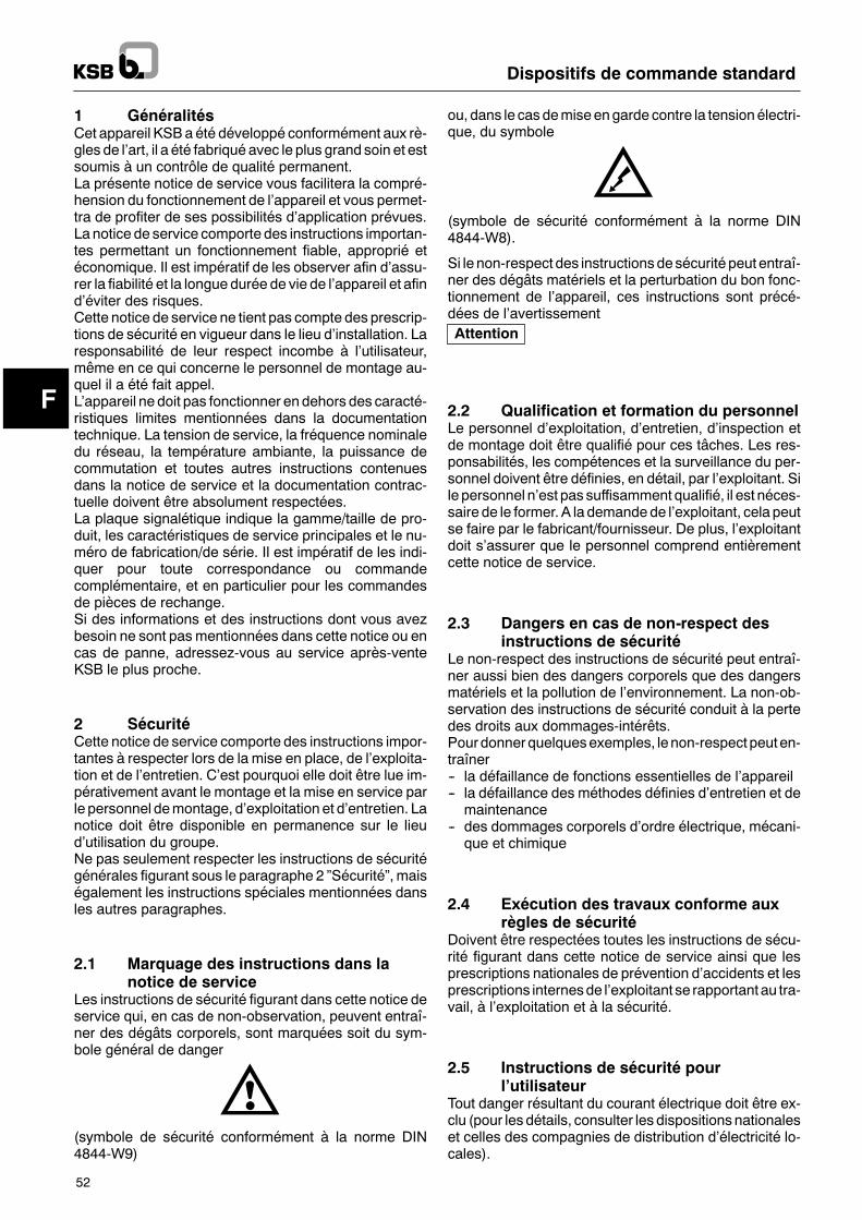
F
Attention
Dispositifs de commande standard
52
1 GénéralitésCet appareil KSB a été développé conformément aux rè-gles de l�art, il a été fabriqué avec le plus grand soin et estsoumis à un contrôle de qualité permanent.La présente notice de service vous facilitera la compré-hension du fonctionnement de l�appareil et vous permet-tra de profiter de ses possibilités d�application prévues.La notice de service comporte des instructions importan-tes permettant un fonctionnement fiable, approprié etéconomique. Il est impératif de les observer afin d�assu-rer la fiabilité et la longue durée de vie de l�appareil et afind�éviter des risques.Cette notice de service ne tient pas compte des prescrip-tions de sécurité en vigueur dans le lieu d�installation. Laresponsabilité de leur respect incombe à l�utilisateur,même en ce qui concerne le personnel de montage au-quel il a été fait appel.L�appareil ne doit pas fonctionner endehors des caracté-ristiques limites mentionnées dans la documentationtechnique. La tension de service, la fréquence nominaledu réseau, la température ambiante, la puissance decommutation et toutes autres instructions contenuesdans la notice de service et la documentation contrac-tuelle doivent être absolument respectées.La plaque signalétique indique la gamme/taille de pro-duit, les caractéristiques de service principales et le nu-méro de fabrication/de série. Il est impératif de les indi-quer pour toute correspondance ou commandecomplémentaire, et en particulier pour les commandesde pièces de rechange.Si des informations et des instructions dont vous avezbesoin ne sont pasmentionnées dans cette notice ou encas de panne, adressez-vous au service après-venteKSB le plus proche.
2 SécuritéCette notice de service comporte des instructions impor-tantes à respecter lors de la mise en place, de l�exploita-tion et de l�entretien. C�est pourquoi elle doit être lue im-pérativement avant le montage et la mise en service parle personnel demontage, d�exploitation et d�entretien. Lanotice doit être disponible en permanence sur le lieud�utilisation du groupe.Ne pas seulement respecter les instructions de sécuritégénérales figurant sous le paragraphe 2 �Sécurité�, maiségalement les instructions spéciales mentionnées dansles autres paragraphes.
2.1 Marquage des instructions dans lanotice de service
Les instructions de sécurité figurant dans cette notice deservice qui, en cas de non-observation, peuvent entraî-ner des dégâts corporels, sont marquées soit du sym-bole général de danger
(symbole de sécurité conformément à la norme DIN4844-W9)
ou, dans le casdemiseengarde contre la tensionélectri-que, du symbole
(symbole de sécurité conformément à la norme DIN4844-W8).
Si le non-respect des instructions desécurité peut entraî-ner des dégâts matériels et la perturbation du bon fonc-tionnement de l�appareil, ces instructions sont précé-dées de l�avertissement
2.2 Qualification et formation du personnelLe personnel d�exploitation, d�entretien, d�inspection etde montage doit être qualifié pour ces tâches. Les res-ponsabilités, les compétences et la surveillance du per-sonnel doivent être définies, en détail, par l�exploitant. Sile personnel n�est pas suffisamment qualifié, il est néces-saire de le former. A la demande de l�exploitant, cela peutse faire par le fabricant/fournisseur. De plus, l�exploitantdoit s�assurer que le personnel comprend entièrementcette notice de service.
2.3 Dangers en cas de non-respect desinstructions de sécurité
Le non-respect des instructions de sécurité peut entraî-ner aussi bien des dangers corporels que des dangersmatériels et la pollution de l�environnement. La non-ob-servation des instructions de sécurité conduit à la pertedes droits aux dommages-intérêts.Pourdonnerquelquesexemples, lenon-respectpeuten-traîner-- la défaillance de fonctions essentielles de l�appareil-- la défaillance des méthodes définies d�entretien et demaintenance
-- des dommages corporels d�ordre électrique, mécani-que et chimique
2.4 Exécution des travaux conforme auxrègles de sécurité
Doivent être respectées toutes les instructions de sécu-rité figurant dans cette notice de service ainsi que lesprescriptions nationales de prévention d�accidents et lesprescriptions internesde l�exploitant se rapportantau tra-vail, à l�exploitation et à la sécurité.
2.5 Instructions de sécurité pourl�utilisateur
Tout danger résultant du courant électrique doit être ex-clu (pour les détails, consulter les dispositions nationaleset celles des compagnies de distribution d�électricité lo-cales).
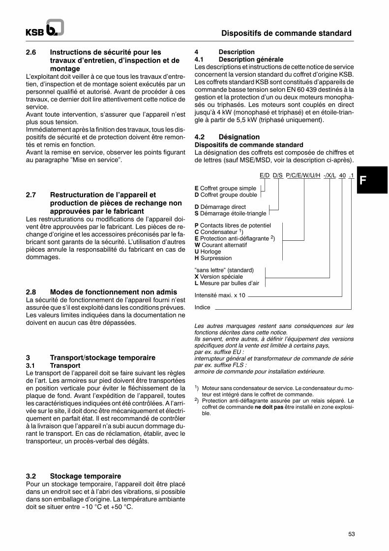
F
Dispositifs de commande standard
53
2.6 Instructions de sécurité pour lestravaux d�entretien, d�inspection et demontage
L�exploitant doit veiller à ce que tous les travaux d�entre-tien, d�inspection et de montage soient exécutés par unpersonnel qualifié et autorisé. Avant de procéder à cestravaux, ce dernier doit lire attentivement cette notice deservice.Avant toute intervention, s�assurer que l�appareil n�estplus sous tension.Immédiatement après la finition des travaux, tous les dis-positifs de sécurité et de protection doivent être remon-tés et remis en fonction.Avant la remise en service, observer les points figurantau paragraphe �Mise en service�.
2.7 Restructuration de l�appareil etproduction de pièces de rechange nonapprouvées par le fabricant
Les restructurations ou modifications de l�appareil doi-vent être approuvées par le fabricant. Les pièces de re-change d�origine et les accessoires préconisés par le fa-bricant sont garants de la sécurité. L�utilisation d�autrespièces annule la responsabilité du fabricant en cas dedommages.
2.8 Modes de fonctionnement non admisLa sécurité de fonctionnement de l�appareil fourni n�estassurée que s�il est exploité dans les conditions prévues.Les valeurs limites indiquées dans la documentation nedoivent en aucun cas être dépassées.
3 Transport/stockage temporaire3.1 TransportLe transport de l�appareil doit se faire suivant les règlesde l�art. Les armoires sur pied doivent être transportéesen position verticale pour éviter le fléchissement de laplaque de fond. Avant l�expédition de l�appareil, toutesles caractéristiques indiquées ont été contrôlées. A l�arri-vée sur le site, il doit donc êtremécaniquement et électri-quement en parfait état. Il est recommandé de contrôlerà la livraison que l�appareil n�a subi aucun dommage du-rant le transport. En cas de réclamation, établir, avec letransporteur, un procès-verbal des dégâts.
3.2 Stockage temporairePour un stockage temporaire, l�appareil doit être placédans un endroit sec et à l�abri des vibrations, si possibledans son emballage d�origine. La température ambiantedoit se situer entre --10 !C et +50 !C.
4 Description4.1 Description généraleLesdescriptionset instructionsde cettenotice deserviceconcernent la version standard du coffret d�origine KSB.Les coffrets standardKSBsont constitués d�appareils decommande basse tension selon EN 60 439 destinés à lagestion et la protection d�un ou deux moteurs monopha-sés ou triphasés. Les moteurs sont couplés en directjusqu�à 4 kW (monophasé et triphasé) et en étoile-trian-gle à partir de 5,5 kW (triphasé uniquement).
4.2 DésignationDispositifs de commande standardLa désignation des coffrets est composée de chiffres etde lettres (sauf MSE/MSD, voir la description ci-après).
E/D D/S P/C/E/W/U/H -/X/L 40 .1
E Coffret groupe simpleD Coffret groupe double
D Démarrage directS Démarrage étoile-triangle
P Contacts libres de potentielC Condensateur 1)E Protection anti-déflagrante 2)W Courant alternatifU HorlogeH Surpression
�sans lettre� (standard)X Version spécialeL Mesure par bulles d�air
Intensité maxi. x 10
Indice
Les autres marquages restent sans conséquences sur lesfonctions décrites dans cette notice.Ils servent, entre autres, à définir l�équipement des versionsspécifiques dont la vente est limitée à certains pays,par ex. suffixe EU :interrupteur général et transformateur de commande de sériepar ex. suffixe FLS :armoire de commande pour installation extérieure.
1) Moteur sans condensateur de service. Le condensateur dumo-teur est intégré dans le coffret de commande.
2) Protection anti-déflagrante assurée par un relais séparé. Lecoffret de commande ne doit pas être installé en zone explosi-ble.
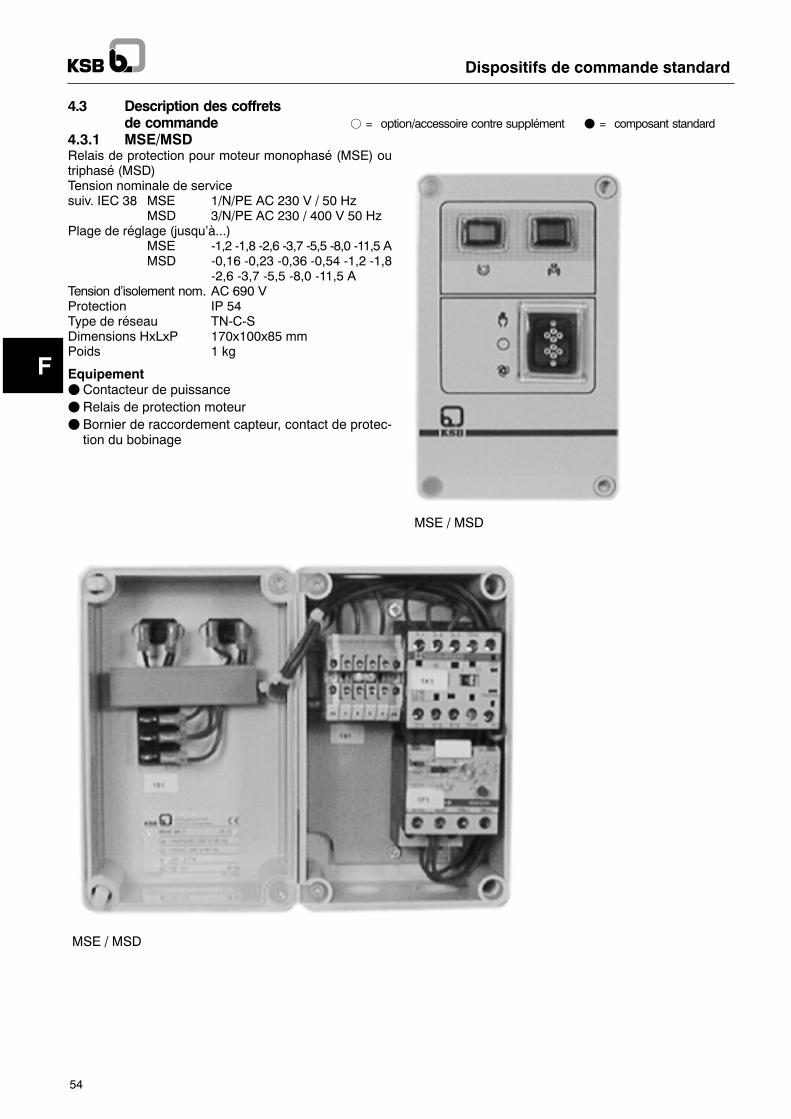
F
Dispositifs de commande standard
54
4.3 Description des coffretsde commande f = "#$%"&'())*++"%,* )"&$,* +-##./0*&$ F = composant standard
4.3.1 MSE/MSDRelais de protection pour moteur monophasé (MSE) outriphasé (MSD)Tension nominale de servicesuiv. IEC 38 MSE 1/N/PE AC 230 V / 50 Hz
MSD 3/N/PE AC 230 / 400 V 50 HzPlage de réglage (jusqu�à...)
MSE -1,2 -1,8 -2,6 -3,7 -5,5 -8,0 -11,5 AMSD -0,16 -0,23 -0,36 -0,54 -1,2 -1,8
-2,6 -3,7 -5,5 -8,0 -11,5 ATension d�isolement nom. AC 690 VProtection IP 54Type de réseau TN-C-SDimensions HxLxP 170x100x85 mmPoids 1 kg
EquipementFContacteur de puissanceFRelais de protection moteurF Bornier de raccordement capteur, contact de protec-tion du bobinage
MSE / MSD
MSE / MSD
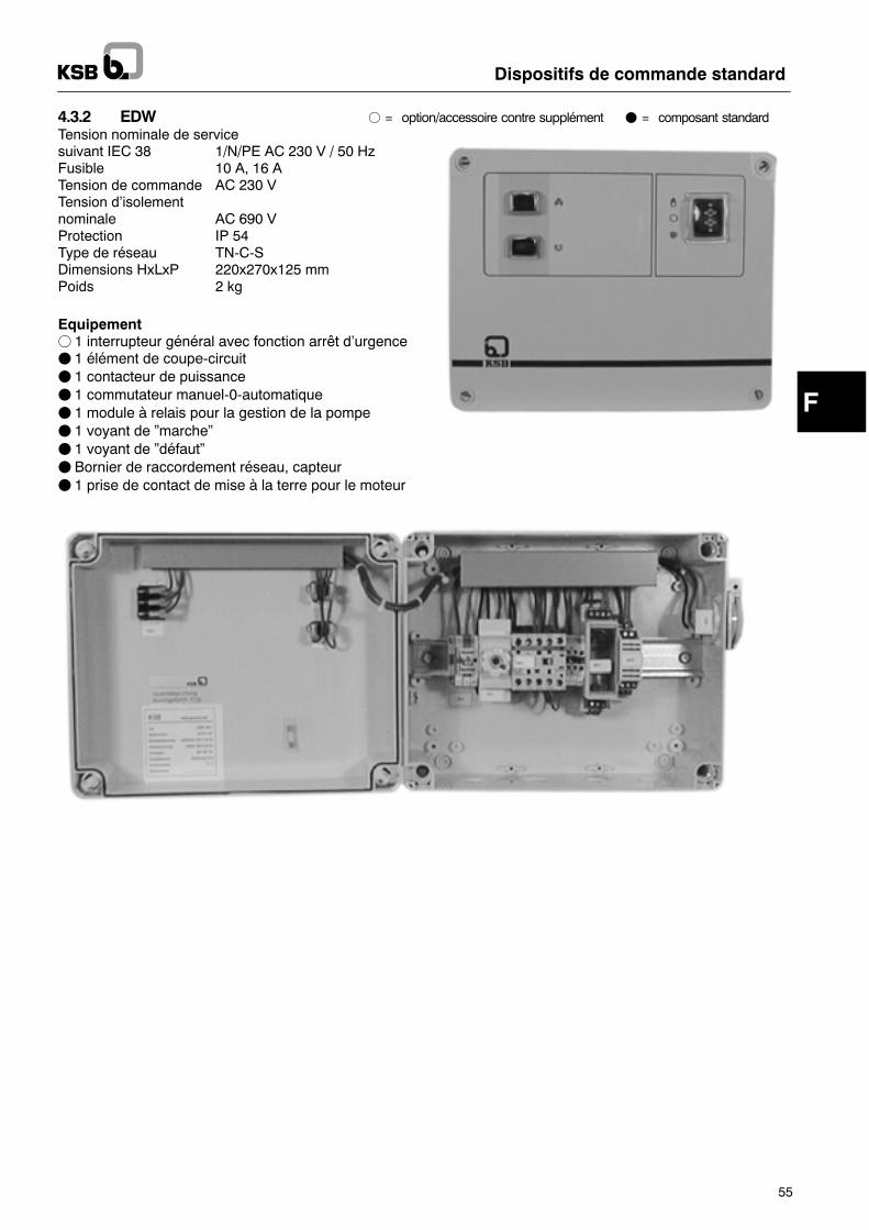
FF
Dispositifs de commande standard
55
4.3.2 EDW f = "#$%"&'())*++"%,* )"&$,* +-##./0*&$ F = composant standardTension nominale de servicesuivant IEC 38 1/N/PE AC 230 V / 50 HzFusible 10 A, 16 ATension de commande AC 230 VTension d�isolementnominale AC 690 VProtection IP 54Type de réseau TN-C-SDimensions HxLxP 220x270x125 mmPoids 2 kg
Equipementf 1 interrupteur général avec fonction arrêt d�urgenceF 1 élément de coupe-circuitF 1 contacteur de puissanceF 1 commutateur manuel-0-automatiqueF 1 module à relais pour la gestion de la pompeF 1 voyant de �marche�F 1 voyant de �défaut�F Bornier de raccordement réseau, capteurF 1 prise de contact de mise à la terre pour le moteur
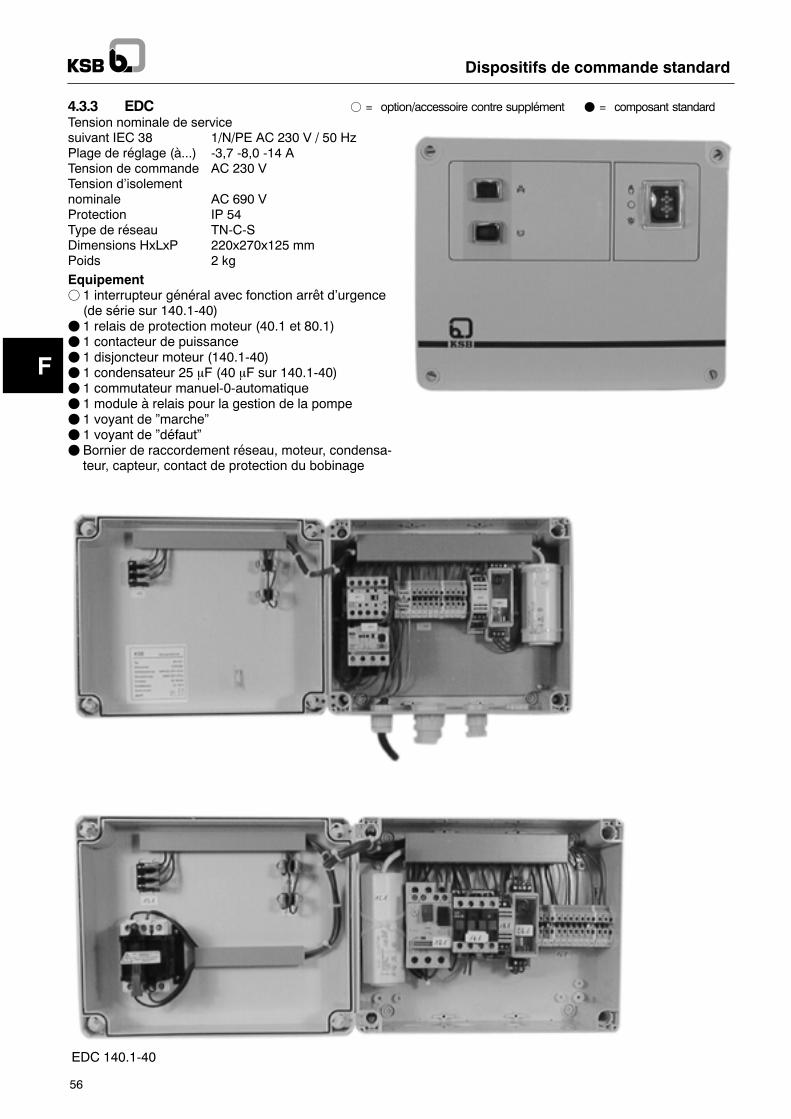
F
Dispositifs de commande standard
56
4.3.3 EDC f = "#$%"&'())*++"%,* )"&$,* +-##./0*&$ F = composant standardTension nominale de servicesuivant IEC 38 1/N/PE AC 230 V / 50 HzPlage de réglage (à...) -3,7 -8,0 -14 ATension de commande AC 230 VTension d�isolementnominale AC 690 VProtection IP 54Type de réseau TN-C-SDimensions HxLxP 220x270x125 mmPoids 2 kg
Equipementf 1 interrupteur général avec fonction arrêt d�urgence(de série sur 140.1-40)
F 1 relais de protection moteur (40.1 et 80.1)F 1 contacteur de puissanceF 1 disjoncteur moteur (140.1-40)F 1 condensateur 25 mF (40 mF sur 140.1-40)F 1 commutateur manuel-0-automatiqueF 1 module à relais pour la gestion de la pompeF 1 voyant de �marche�F 1 voyant de �défaut�F Bornier de raccordement réseau, moteur, condensa-teur, capteur, contact de protection du bobinage
EDC
EDC 140.1-40
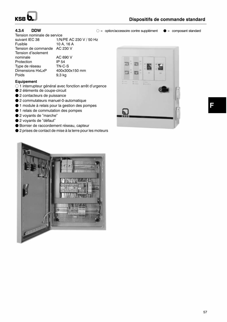
F
Dispositifs de commande standard
57
4.3.4 DDW f = "#$%"&'())*++"%,* )"&$,* +-##./0*&$ F = composant standardTension nominale de servicesuivant IEC 38 1/N/PE AC 230 V / 50 HzFusible 10 A, 16 ATension de commande AC 230 VTension d�isolementnominale AC 690 VProtection IP 54Type de réseau TN-C-SDimensions HxLxP 400x300x150 mmPoids 9,3 kg
Equipementf 1 interrupteur général avec fonction arrêt d�urgenceF 2 éléments de coupe-circuitF 2 contacteurs de puissanceF 2 commutateurs manuel-0-automatiqueF 1 module à relais pour la gestion des pompesF 1 relais de commutation des pompesF 2 voyants de �marche�F 2 voyants de �défaut�F Bornier de raccordement réseau, capteurF 2 prises de contact demise à la terre pour lesmoteurs
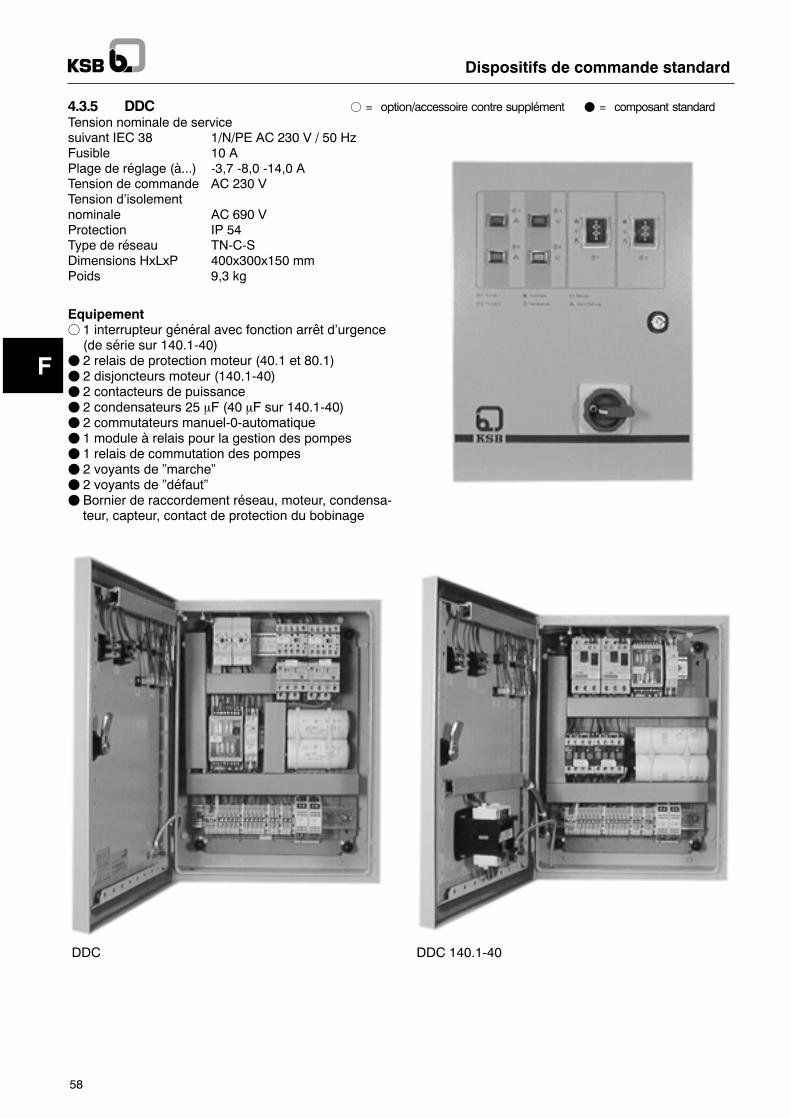
F
Dispositifs de commande standard
58
4.3.5 DDC f = "#$%"&'())*++"%,* )"&$,* +-##./0*&$ F = composant standardTension nominale de servicesuivant IEC 38 1/N/PE AC 230 V / 50 HzFusible 10 APlage de réglage (à...) -3,7 -8,0 -14,0 ATension de commande AC 230 VTension d�isolementnominale AC 690 VProtection IP 54Type de réseau TN-C-SDimensions HxLxP 400x300x150 mmPoids 9,3 kg
Equipementf 1 interrupteur général avec fonction arrêt d�urgence(de série sur 140.1-40)
F 2 relais de protection moteur (40.1 et 80.1)F 2 disjoncteurs moteur (140.1-40)F 2 contacteurs de puissanceF 2 condensateurs 25 mF (40 mF sur 140.1-40)F 2 commutateurs manuel-0-automatiqueF 1 module à relais pour la gestion des pompesF 1 relais de commutation des pompesF 2 voyants de �marche�F 2 voyants de �défaut�F Bornier de raccordement réseau, moteur, condensa-teur, capteur, contact de protection du bobinage
DDC DDC 140.1-40
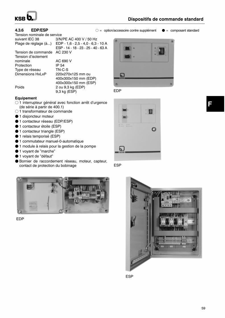
F
Dispositifs de commande standard
59
4.3.6 EDP/ESP f = "#$%"&'())*++"%,* )"&$,* +-##./0*&$ F = composant standardTension nominale de servicesuivant IEC 38 3/N/PE AC 400 V / 50 HzPlage de réglage (à...) EDP - 1,6 - 2,5 - 4,0 - 6,3 - 10 A
ESP - 14 - 18 - 23 - 25 - 40 - 63 ATension de commande AC 230 VTension d�isolementnominale AC 690 VProtection IP 54Type de réseau TN-C-SDimensions HxLxP 220x270x125 mm ou
400x300x150 mm (EDP)400x300x150 mm (ESP)
Poids 2 ou 9,3 kg (EDP)9,3 kg (ESP)
Equipementf 1 interrupteur général avec fonction arrêt d�urgence(de série à partir de 400.1)
f 1 transformateur de commandeF 1 disjoncteur moteurF 1 contacteur réseau (EDP/ESP)F 1 contacteur étoile (ESP)F 1 contacteur triangle (ESP)F 1 relais temporisé (ESP)F 1 commutateur manuel-0-automatiqueF 1 module à relais pour la gestion de la pompeF 1 voyant de �marche�F 1 voyant de �défaut�F Bornier de raccordement réseau, moteur, capteur,contact de protection du bobinage
EDP
ESP
EDP
ESP
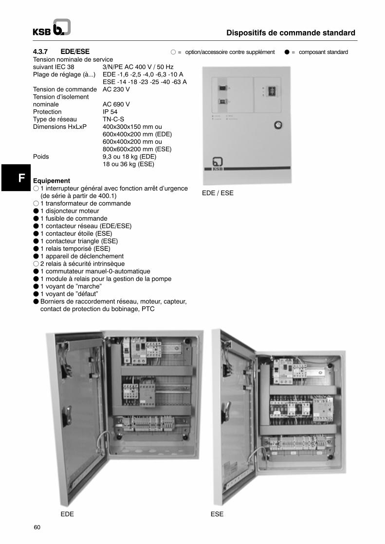
F
Dispositifs de commande standard
60
4.3.7 EDE/ESE f = "#$%"&'())*++"%,* )"&$,* +-##./0*&$ F = composant standardTension nominale de servicesuivant IEC 38 3/N/PE AC 400 V / 50 HzPlage de réglage (à...) EDE -1,6 -2,5 -4,0 -6,3 -10 A
ESE -14 -18 -23 -25 -40 -63 ATension de commande AC 230 VTension d�isolementnominale AC 690 VProtection IP 54Type de réseau TN-C-SDimensions HxLxP 400x300x150 mm ou
600x400x200 mm (EDE)600x400x200 mm ou800x600x200 mm (ESE)
Poids 9,3 ou 18 kg (EDE)18 ou 36 kg (ESE)
Equipementf 1 interrupteur général avec fonction arrêt d�urgence(de série à partir de 400.1)
f 1 transformateur de commandeF 1 disjoncteur moteurF 1 fusible de commandeF 1 contacteur réseau (EDE/ESE)F 1 contacteur étoile (ESE)F 1 contacteur triangle (ESE)F 1 relais temporisé (ESE)F 1 appareil de déclenchementf 2 relais à sécurité intrinsèqueF 1 commutateur manuel-0-automatiqueF 1 module à relais pour la gestion de la pompeF 1 voyant de �marche�F 1 voyant de �défaut�F Borniers de raccordement réseau, moteur, capteur,contact de protection du bobinage, PTC
EDE / ESE
ESEEDE
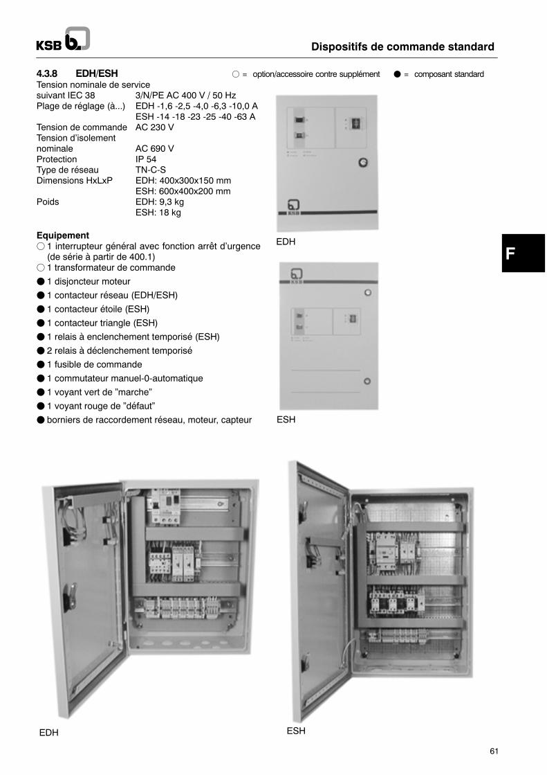
F
Dispositifs de commande standard
61
4.3.8 EDH/ESH f = "#$%"&'())*++"%,* )"&$,* +-##./0*&$ F = composant standardTension nominale de servicesuivant IEC 38 3/N/PE AC 400 V / 50 HzPlage de réglage (à...) EDH -1,6 -2,5 -4,0 -6,3 -10,0 A
ESH -14 -18 -23 -25 -40 -63 ATension de commande AC 230 VTension d�isolementnominale AC 690 VProtection IP 54Type de réseau TN-C-SDimensions HxLxP EDH: 400x300x150 mm
ESH: 600x400x200 mmPoids EDH: 9,3 kg
ESH: 18 kg
Equipementf 1 interrupteur général avec fonction arrêt d�urgence(de série à partir de 400.1)
f 1 transformateur de commande
F 1 disjoncteur moteur
F 1 contacteur réseau (EDH/ESH)
F 1 contacteur étoile (ESH)
F 1 contacteur triangle (ESH)
F 1 relais à enclenchement temporisé (ESH)
F 2 relais à déclenchement temporisé
F 1 fusible de commande
F 1 commutateur manuel-0-automatique
F 1 voyant vert de �marche�
F 1 voyant rouge de �défaut�
F borniers de raccordement réseau, moteur, capteur
EDH
ESH
EDH ESH
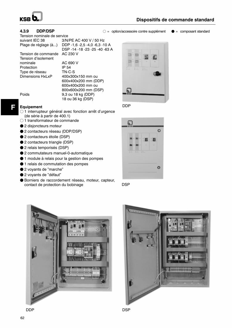
F
Dispositifs de commande standard
62
4.3.9 DDP/DSP f = "#$%"&'())*++"%,* )"&$,* +-##./0*&$ F = composant standardTension nominale de servicesuivant IEC 38 3/N/PE AC 400 V / 50 HzPlage de réglage (à...) DDP -1,6 -2,5 -4,0 -6,3 -10 A
DSP -14 -18 -23 -25 -40 -63 ATension de commande AC 230 VTension d�isolementnominale AC 690 VProtection IP 54Type de réseau TN-C-SDimensions HxLxP 400x300x150 mm ou
600x400x200 mm (DDP)600x400x200 mm ou800x600x200 mm (DSP)
Poids 9,3 ou 18 kg (DDP)18 ou 36 kg (DSP)
Equipementf 1 interrupteur général avec fonction arrêt d�urgence(de série à partir de 400.1)
f 1 transformateur de commandeF 2 disjoncteurs moteurF 2 contacteurs réseau (DDP/DSP)F 2 contacteurs étoile (DSP)F 2 contacteurs triangle (DSP)F 2 relais temporisés (DSP)F 2 commutateurs manuel-0-automatiqueF 1 module à relais pour la gestion des pompesF 1 relais de commutation des pompesF 2 voyants de �marche�F 2 voyants de �défaut�F Borniers de raccordement réseau, moteur, capteur,contact de protection du bobinage
DDP
DSP
DDP DSP
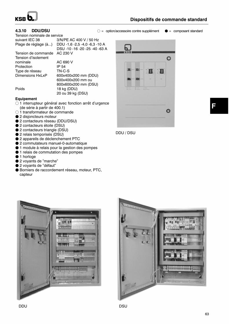
F
Dispositifs de commande standard
63
4.3.10 DDU/DSU f = "#$%"&'())*++"%,* )"&$,* +-##./0*&$ F = composant standardTension nominale de servicesuivant IEC 38 3/N/PE AC 400 V / 50 HzPlage de réglage (à...) DDU -1,6 -2,5 -4,0 -6,3 -10 A
DSU -10 -16 -20 -25 -40 -63 ATension de commande AC 230 VTension d�isolementnominale AC 690 VProtection IP 54Type de réseau TN-C-SDimensions HxLxP 600x400x200 mm (DDU)
600x400x200 mm ou800x600x200 mm (DSU)
Poids 18 kg (DDU)20 ou 39 kg (DSU)
Equipementf 1 interrupteur général avec fonction arrêt d�urgence(de série à partir de 400.1)
f 1 transformateur de commandeF 2 disjoncteurs moteurF 2 contacteurs réseau (DDU/DSU)F 2 contacteurs étoile (DSU)F 2 contacteurs triangle (DSU)F 2 relais temporisés (DSU)F 2 appareils de déclenchement PTCF 2 commutateurs manuel-0-automatiqueF 1 module à relais pour la gestion des pompesF 1 relais de commutation des pompesF 1 horlogeF 2 voyants de �marche�F 2 voyants de �défaut�F Borniers de raccordement réseau, moteur, PTC,capteur
DDU / DSU
fehltDDU folgt neuvon BOE
DDU DSU
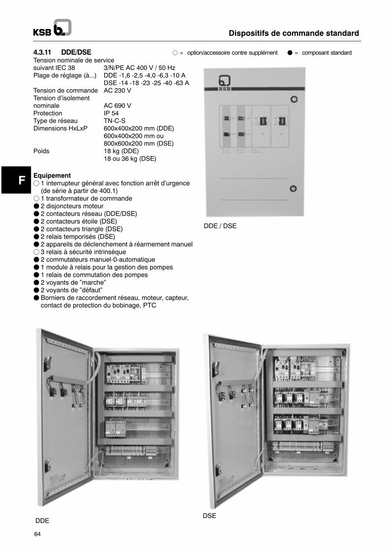
F
Dispositifs de commande standard
64
4.3.11 DDE/DSE f = "#$%"&'())*++"%,* )"&$,* +-##./0*&$ F = composant standardTension nominale de servicesuivant IEC 38 3/N/PE AC 400 V / 50 HzPlage de réglage (à...) DDE -1,6 -2,5 -4,0 -6,3 -10 A
DSE -14 -18 -23 -25 -40 -63 ATension de commande AC 230 VTension d�isolementnominale AC 690 VProtection IP 54Type de réseau TN-C-SDimensions HxLxP 600x400x200 mm (DDE)
600x400x200 mm ou800x600x200 mm (DSE)
Poids 18 kg (DDE)18 ou 36 kg (DSE)
Equipementf 1 interrupteur général avec fonction arrêt d�urgence(de série à partir de 400.1)
f 1 transformateur de commandeF 2 disjoncteurs moteurF 2 contacteurs réseau (DDE/DSE)F 2 contacteurs étoile (DSE)F 2 contacteurs triangle (DSE)F 2 relais temporisés (DSE)F 2 appareils de déclenchement à réarmement manuelf 3 relais à sécurité intrinsèqueF 2 commutateurs manuel-0-automatiqueF 1 module à relais pour la gestion des pompesF 1 relais de commutation des pompesF 2 voyants de �marche�F 2 voyants de �défaut�F Borniers de raccordement réseau, moteur, capteur,contact de protection du bobinage, PTC
DDE / DSE
DDEDSE
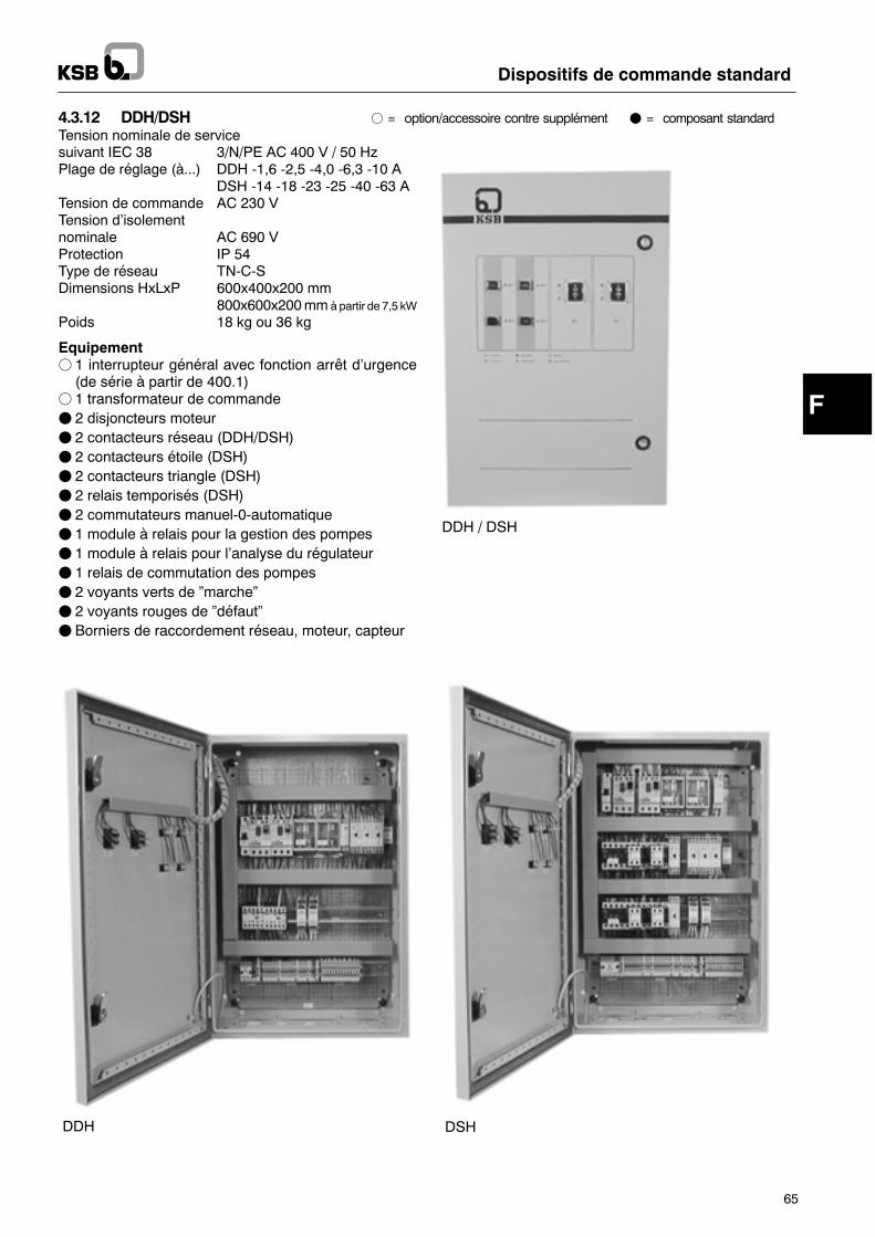
F
Dispositifs de commande standard
65
4.3.12 DDH/DSH f = "#$%"&'())*++"%,* )"&$,* +-##./0*&$ F = composant standardTension nominale de servicesuivant IEC 38 3/N/PE AC 400 V / 50 HzPlage de réglage (à...) DDH -1,6 -2,5 -4,0 -6,3 -10 A
DSH -14 -18 -23 -25 -40 -63 ATension de commande AC 230 VTension d�isolementnominale AC 690 VProtection IP 54Type de réseau TN-C-SDimensions HxLxP 600x400x200 mm
800x600x200mmàpartir de 7,5 kWPoids 18 kg ou 36 kg
Equipementf 1 interrupteur général avec fonction arrêt d�urgence(de série à partir de 400.1)
f 1 transformateur de commandeF 2 disjoncteurs moteurF 2 contacteurs réseau (DDH/DSH)F 2 contacteurs étoile (DSH)F 2 contacteurs triangle (DSH)F 2 relais temporisés (DSH)F 2 commutateurs manuel-0-automatiqueF 1 module à relais pour la gestion des pompesF 1 module à relais pour l�analyse du régulateurF 1 relais de commutation des pompesF 2 voyants verts de �marche�F 2 voyants rouges de �défaut�F Borniers de raccordement réseau, moteur, capteur
DDH / DSH
DDH DSH
Attention
Dispositifs de commande standard
66
4.4 Options-- compteur horaire-- ampèremètre-- interrupteur général (de série à partir de coffret 400.1et 630.1)
-- voltmètre-- branchement des thermistances avec appareil de dé-clenchement (de série à partir de 400.1 et DDU/DSU)
-- relais de surveillance (ordre et absence de phases,surtension/sous-tension)
-- autres options sur demande
5 Mise en place/installation5.1 Conditions ambiantesInstallation-- dans un endroit sec, à l�abri du gel,-- bien aéré,-- verrouillable (sans accès de personnes non autori-sées)
L�armoire doit être installée à l�abri des inondations.Les dispositifs de commande étant exécutés sans pro-tection antidéflagrante, ils ne doivent pas être utilisés enzone explosible.
5.2 Branchement électriqueF Lebranchement électrique doit être réalisé par unper-sonnel qualifié.
FRespecter les conditions de branchement du serviced�électricité local.
F Vérifier le type de courant et la tension du secteur.
FRéaliser le branchement dumoteur conformément auschéma de connexion.
FRégler le disjoncteur moteur sur l�intensité nominale.
F Le câble de raccordement électrique doit être dimen-sionné suivant les normes en vigueur dans le paysd�installation.
F Protection maxi. par fusibles selon le schéma deconnexion.
En triphasé, le câble de puissance doit être raccordé demanière à ce que le sens de rotation desmoteurs soit ho-raire (à droite). Enmonophasé, veiller à brancher correc-tement la phase et le conducteur neutre.Ne doivent être raccordées que des pompes KSBdont les caractéristiques techniques sont compati-bles avec le coffret de commande.Le raccordement d�autres appareils est interdit enraison du risque de dommages pouvant être causésau niveau du coffret de commande.Seconformeraubranchement duschémadeconnexion.FRéglage de l�interrupteur à flotteur selon les indica-tions du schéma de connexion.
F Le contact de protection du bobinage doit être reliéaux conducteurs correspondants du câble de pompe.
Dans le casdepompes sans contact deprotectiondubo-binage, il faut ponter les bornes correspondantes dansle coffret de commande.
6 Mise en service/mise hors service6.1 GénéralitésAvant la mise en service du coffret de commande :s�assurer que les normes et règlements en vigeur ont étéobservés et faire vérifier les points suivants par un élec-tricien qualifié :-- raccordement du câble de pompe-- raccordement de la protection thermique (contact deprotection du bobinage)
-- raccordement correct du câble d�alimentation (en tri-phasé : rotation dans le sens horaire)
-- raccordement et réglage des capteurs (interrupteur àflotteur, contacteur manométrique, horloge). Pourcela, se conformer aux paragraphes 6.2.1 à 6.2.4.
Ces travaux réalisés, le coffret peut être mis en service.Pour cela, consulter impérativement le plan deconnexion du schéma électrique ainsi que la noticede service de la pompe.
6.2 Mise en service
Les travaux suivants doivent être systématiquement ef-fectués en se conformant aux paragraphes 6.2.1 à 6.2.4ci-après.-- Mettre l�interrupteur général sur �0�.-- Mettre le commutateurmanuel-0-automatique sur �0�.-- Comparer la valeur de réglage du disjoncteur moteurà l�intensité nominale dumoteur et corriger le réglage,le cas échéant.
-- Mettre le disjoncteur moteur sur �I�.-- Au départ de l�usine, le relais temporisé assurant lacommutation étoile-triangle est réglé sur 3 secondes;ce réglage doit être adapté si nécessaire.
-- Pour établir l�alimentation électrique, mettre le fusible del�installation (par ex. automate) en position �Marche�.
-- Si un interrupteur général est prévu,mettre celui-ci sur �I�.-- Pour les moteurs triphasés, contrôler le sens de rota-tionen réglant le commutateurmanuel-0-automatiquebrièvement sur �manuel� (uniquement si le niveaud�eau est supérieur au niveau d�arrêt ou la pression in-férieure à la pression d�arrêt).Observer la notice de service de la pompe ou de l�in-stallation.
6.2.1 Dispositifs de commande simples oudoubles, commandés par le niveau d�eau
Le démarrage et l�arrêt de la (des) pompe(s) sont assu-rés par un (deux) interrupteur(s) à flotteur, capteur(s) deniveau ou interrupteur(s) magnétique(s).Les niveaux de commutation doivent être réglés surplace : Pour cela, fixer le câble de l�interrupteur à flotteursur la tuyauterie de refoulement, la poignée ou d�autrespoints à la hauteur souhaitée, et choisir la longueur nuedu câble de l�interrupteur à flotteur en conséquence. Lecâbledoit dépasser d�aumoins10 cmdesagainedepro-tection pour garantir un fonctionnement irréprochable ycompris lorsque le câble est froid et rigide. Le systèmecommande l�enclenchement de la pompe lorsque le flot-teur est incliné vers le haut dans un angle d�environ 30!;il commande l�arrêt lorsque le flotteur est incliné vers lebas dans un angle de 30 ! (bruit de commutation bien au-dible dans le corps de flotteur). La distanceminimumen-tre les deux points de commutation est d�environ 40 cm.
F
Dispositifs de commande standard
67
Régler les points de commutation de façon à ce que lapompe soit déconnectée avant que la nappe atteigne lestrous d�amorçage du pied. L�enclenchement doit interve-nir avant que le niveau d�eau atteigne le bord supérieurde la cuve. L�interrupteur à flotteur ne doit ni venir se po-ser sur le fond de la cuve, ni heurter son couvercle (siexistant). Demême, il faut exclure que le flotteur ne restecoincé dans la cuve (saillies, etc.).En cas de 2 pompes et utilisation d�un dispositif de com-mande double, les deux interrupteurs à flotteur doiventêtre disposés en cascade. On obtient alors trois fonc-tions :1. Permutation des deux pompes à chaque enclenche-ment.
2.Enclenchementde lapompehors servicepourassurerle débit de pointe (fonctionnement parallèle).
3.En casdedéfaut de la pompede service, commutationautomatique sur l�autre pompe.
6.2.2 Dispositifs de commande simples,commandés par la pression
Le démarrage et l�arrêt de la pompe sont assurés à tra-vers un contacteur manométrique installé sur la tuyaute-rie de refoulement.La qualité et la conception du contacteur doivent êtrecompatibles avec le fluide véhiculé.Le contacteur manométrique doit être réglé selon la no-tice jointe. Le relais temporisé correspondant au contac-teur (voir schéma électrique) empêche le battement del�installation à condition qu�il soit correctement réglé etadapté à l�hydraulique. Ceci limite la fréquence de dé-marrage en cas de faible débit. La durée de la temporisa-tion est réglée sur place.A l�aspiration, un interrupteur à flotteur, un contacteurmanométrique ou des électrodes (option) protègent lapompe contre un manque d�eau éventuel.Un relais temporisé ou un relais à électrodes évite le bat-tement de l�installation lorsque leniveaud�eauou lapres-sion nécessaire n�est pas atteinte temporairement. Latemporisation doit être adaptée à l�installation.En installant l�interrupteur à flotteur, il faut veiller à ce qu�ilait la pleine liberté demouvement. Il doit pouvoir assurerla déconnexion sûre de la pompe en cas de niveau d�eauminimum. En aucun cas, le flotteur ne doit heurter lefond ou le couvercle de la cuve.Les électrodes doivent être installées dans la cuve de lamanière suivante :Connecter l�électrodeau câble d�électrode selon la notice.Faire descendre l�électrode de masse presque jusqu�aufond de la cuve. Elle doit pouvoir flotter librement.Suspendre la deuxième électrode dans la cuve de sorteque la distance entre le bord inférieur de l�électrode et lefondde la cuve correspondeauniveaud�eaumini admis-sible.Régler le contacteur manométrique sur la pression d�as-piration mini. admissible selon la notice jointe.
6.2.3 Dispositifs de commande doubles,commandés par horloge
Le dispositif de commande double comporte différentesfonctionspouvant êtreactivéespar despersonnesexter-nes à travers des contacts libres de potentiel.
-- Déblocage externe -- enlever le pontage conformé-ment au schémaélectrique et brancher le contact librede potentiel.
-- Débit depointe externe -- par contact libre depotentiel.-- Permutation des pompes externe -- mettre le commu-tateurdu relais degestiondespompesenposition �ex-terne� (réglage initial �interne�). Brancher un contactO/F libre de potentiel sans position zéro conformé-ment au schéma électrique. Les pompes sont alorspermutées à travers ce contact.
Les contacts de commutation de ces fonc-tions externes doivent être dimensionnéspour 230 V/50 Hz, 1 Aind mini.
L�horloge intégrée permet de réaliser la permutation in-terne des pompes. Après avoir branché l�appareil électri-quement, programmer l�horloge en commençant par en-trer l�heure actuelle et le jour de semaine. Dans undeuxième temps, programmer les heures de permuta-tion. L�opération de programmation peut varier selon lamarque; elle est expliquée dans la notice fournie avecl�horloge.
6.2.4 Dispositifs de commande doubles,commandés par la pression
Le démarrage et l�arrêt des pompes sont assurés à tra-vers un régulateur par plus ou moins, installé sur latuyauterie de refoulement. La qualité et la conception dece régulateur doivent être compatibles avec le fluide vé-hiculé.Régler le régulateur selon la notice jointe.Les relais assurant les fonctions �temporisation d�arrêt�et �débit de pointe� (voir schéma électrique) sont préré-glés à l�usine et empêchent le battement de l�installation.En cas de conditions d�installation défavorables, il fautéventuellementmodifier ces réglages. Il est alors recom-mandé de noter les nouveaux temps dans le schémaélectrique.A l�aspiration, un interrupteur à flotteur, un contacteurmanométrique ou des électrodes (option) protègent lapompe contre un manque d�eau éventuel.Un relais temporisé ou un relais à électrodes évite le bat-tement de l�installation lorsque leniveaud�eauou lapres-sion nécessaire n�est pas atteinte temporairement. Latemporisation doit être adaptée à l�installation.En installant l�interrupteur à flotteur, il faut veiller à ce qu�ilait la pleine liberté demouvement. Il doit pouvoir assurerla déconnexion sûre de la pompe en cas de niveau d�eaumini. En aucun cas, le flotteur ne doit heurter le fond oule couvercle de la cuve.Les électrodes doivent être installées dans la cuve de lamanière suivante :Connecter l�électrode au câble d�électrode selon la no-tice. Faire descendre l�électrode de masse presquejusqu�au fond de la cuve. Elle doit pouvoir flotter libre-ment.Suspendre la deuxième électrode dans la cuve de sorteque la distance entre le bord inférieur de l�électrode et lefondde la cuve correspondeauniveaud�eaumini admis-sible.Régler le contacteur manométrique sur la pression d�as-pirationmini. admissible selon la notice jointe au contac-teur.
F
Dispositifs de commande standard
68
6.3 Description des fonctionsDispositif de commande simple
6.3.1 Fonctionnement automatique --système commandé par le niveau
Le moteur est enclenché et arrêté via un commutateurtrois positions (manuel-0-automatique).Position �0� : Le moteur est arrêté.Position �automatique� : Lemoteur est enclenché et ar-
rêté au moyen d�un capteurexterne.
Position �manuel� : Permet l�enclenchement ma-nuel du moteur.
Vidanged�un réservoir/d�une fosse; capteurde l�interrup-teur à flotteur fermé en position haute.La pompe est enclenchée et arrêtée en fonction du ni-veau. Lorsque le liquide véhiculé atteint le niveaud�enclenchement de l�interrupteur à flotteur, la pompeestenclenchée etmaintenue en service jusqu�à ce que le ni-veau de liquide atteigne le niveau d�arrêt de l�interrupteurà flotteur.En position �manuel�, la pompe peut être enclenchée di-rectement. S�assurer auparavant que le niveau du li-quide soit supérieur au niveau d�arrêt de l�interrupteurà flotteur. Le mode manuel doit être réservé aux fonc-tionnements de courte durée comme par exemple lecontrôle du sens de rotation.Dans tous les autres cas, l�interrupteur doit être réglé sur�automatique� avant de mettre l�installation en service.
6.3.2 Fonctionnement automatique --système commandé par la pression
Le moteur est enclenché et arrêté via un commutateurtrois positions (manuel-0-automatique).Position �0� : Le moteur est arrêté.Position �automatique� : Lemoteur est enclenché et ar-
rêté au moyen d�un capteurexterne.
Position �manuel� : Permet l�enclenchement ma-nuel du moteur.
La pompe est enclenchée lorsque la pression de l�instal-lation est inférieure à la valeur réglée sur le contacteurmanométrique. Une durée de fonctionnement minimumest assurée par un relais temporisé. Ce relais peut êtreréglé en fonction des conditions de l�installation. Lapompe est déconnectée lorsque la pression d�arrêt ré-glée sur le contacteur manométrique est atteinte. Làaussi, une temporisation d�arrêt est prévue.La pression d�aspiration est surveillée au moyen d�uncontacteur manométrique installé sur la tuyauterie d�as-piration. Un relais temporisé à réglage individuel évite lebattement de l�installation en cas de chutes temporairesde la pression dans la phasededémarrage. L�installationn�est déconnectée à travers le contacteurmanométriquequesi la pressiond�aspirationminimumn�est pasatteintedans le laps de temps paramétré.Le voyant rouge de manque d�eau signale un manqued�eau ou une pression d�aspiration insuffisante dans latuyauterie d�alimentation. La remiseenservice se fait au-tomatiquementau retourde lapressiond�aspirationmini-
mum. Le voyant rouge de défaut s�allume lorsque le dis-joncteur moteur a déclenché.Même en cas de défaillance de l�automatisme complet,l�enclenchement manuel du groupe reste possible. Pourcela, mettre le commutateur manuel-0-automatique enposition �H�.
6.4 Description des fonctionsDispositif de commande double
6.4.1 Fonctionnement automatique --système commandé par le niveau
Le moteur est enclenché et arrêté via un commutateurtrois positions (manuel-0-automatique). Un commuta-teur par moteur est prévu.Position �0� : Le moteur est arrêté.Position �automatique� : Lemoteur est enclenché et ar-
rêté au moyen d�un capteurexterne.Si les deuxcommuta-teurs sont en position �auto-matique�, les moteurs sontpermutés après chaquecycle.Si l�un des moteurs n�est pasdisponible, l�autre est immé-diatement mis en marche.
Position �manuel� : Permet l�enclenchement ma-nuel du moteur.
Vidange d�un réservoir; capteur de l�interrupteur à flot-teur fermé en position haute.Les pompes sont enclenchées et arrêtées en fonction duniveau. Une permutation a lieu à chaque redémarrage.Aubesoin, la deuxièmepompeest enclenchéeautomati-quement pour assurer le débit de pointe. Lorsque le li-quide véhiculé atteint le niveau d�enclenchement de l�in-terrupteur à flotteur n! 1 (niveau inférieur), la premièrepompe est enclenchée. Celle-ci évacue l�eau jusqu�à ceque le niveau atteigne le niveau d�arrêt de l�interrupteurà flotteur n! 1.Lorsque le niveau d�eau remonte jusqu�à atteindre le ni-veau d�enclenchement de l�interrupteur à flotteur n! 1, ladeuxième pompe est enclenchée et déconnectée lors-que le niveau d�arrêt est atteint. Cette permutation despompes est observée après chaque cycle.Si le niveau de liquide atteint l�interrupteur à flotteur n! 2(niveau supérieur) alors qu�une pompe est en service, lesystème commande l�enclenchement de la deuxièmepompe qui sert alors de pompe d�appoint.Si l�une des pompes n�est plus disponible suite au dé-clenchement du thermorupteur (contact de protection dubobinage), de la thermistancePTCoududisjoncteurmo-teur, le système assure immédiatement la commutationsur la deuxième pompe (pompe de secours).En position �manuel�, chaque pompe peut être en-clenchée directement. S�assurer auparavant que le ni-veau du liquide soit supérieur au niveau d�arrêt de l�inter-rupteur à flotteur. Le mode manuel doit être réservé auxfonctionnements de courte durée commepar exemple lecontrôle du sens de rotation.Dans tous les autres cas, l�interrupteur doit être réglé sur�automatique� avant de mettre l�installation en service.
F
Dispositifs de commande standard
69
6.4.2 Fonctionnement automatique --système commandé par horloge
Le moteur est enclenché et arrêté via un commutateurtrois positions (manuel-0-automatique). Un commuta-teur par moteur est prévu.Position �0� : Le moteur est arrêté.Position �automatique� : Si les deux commutateurs
sont en position �automati-que�, lesmoteurs sont enclen-chés et arrêtés alternative-ment en fonction du tempsprogrammé sur l�horloge inté-grée. Si l�un desmoteurs n�estpas disponible, l�autre est im-médiatement mis en marche.
Position �manuel� : Permet l�enclenchement ma-nuel du moteur.
Si les commutateurs manuel-0-automatique (H-0-A)sont réglés en position �automatique�, les pompes sontpermutées en fonction des heures de commutation pro-grammées sur l�horloge numérique. Cette permutationde la première sur la deuxième pompe peut égalementêtre réalisée à travers le contact externe (si prévu). Pourcela, mettre le commutateur latéral du dispositif de com-mande sur �externe�.Le contact externe de débit de pointe permet d�enclen-cher la deuxième pompe pour un fonctionnement en pa-rallèle des deux pompes. Si le contact de déblocage ex-terne est interrompu, les pompes ne peuvent êtreenclenchées ni en automatique ni en manuel.Si, pendant le fonctionnement d�une pompe, celle-citombe en panne, l�autre pompe est automatiquementmise en service.En position �manuel�, chaque pompe peut être enclen-chée directement. Ce mode de fonctionnement est né-cessaire par exemple pour le contrôle du sens de rota-tion. Si les deux commutateurs M-0-A sont réglés sur�manuel�, un couplage de débit de pointe interne peutêtre réalisé. Dans tous les autres cas de figure, les com-mutateurs doivent être réglés sur �automatique� avant lamise en route de l�installation.
6.4.3 Fonctionnement automatique --système commandé par la pression
Le moteur est enclenché et arrêté via un commutateurtrois positions (manuel-0-automatique). Un commuta-teur par moteur est prévu.Position �0� : Le moteur est arrêté.Position �automatique� : Lemoteur est enclenché et ar-
rêté via un capteur externe. Siles deux commutateurs sonten position �automatique�, lesmoteurs sont permutés aprèschaque cycle de commuta-tion. Si l�un des moteurs n�estpas disponible, l�autre est im-médiatement mis en marche.
Position �manuel� : Permet l�enclenchement ma-nuel du moteur.
L�installation est enclenchée et arrêtée en fonction de lapression. Les impulsions de commutation sont transmi-ses au systèmede commandepar un régulateur par plusoumoins installé sur la tuyauterie de refoulement. L�unitéde commande assure l�enclenchement et l�arrêt despompesen fonctiondesbesoins instantanésetmaintientainsi la pression d�installation entre les limites de pres-sion inférieure et supérieure.Les pompes sont enclenchées enalternance pour équili-brer leur temps de fonctionnement. Si, pendant le fonc-tionnement d�une pompe, celle-ci tombe en panne, l�au-tre pompe (pompe de secous) est automatiquementmise en service sauf en cas de fonctionnement decharge de pointe. Si, après un temps paramétrable, lapression de consigne n�est pas atteinte, la deuxièmepompeest automatiquementmise en route pour un fonc-tionnement parallèle.Lorsque lapressiondusystèmeatteint la pressiond�arrêtpréréglée, une temporisation de maintien à durée para-métrable commence à courir. La pompe (les pompes)n�est arrêtée que si la pression est supérieure à la pres-sion d�arrêt pendant toute la durée de la temporisation.Dans le cas d�une chute temporaire de la pression, lesystème observe une nouvelle temporisation de main-tien. La fréquence de démarrage des pompes en cas depetits débits est ainsi limitée.Pour protéger le systèmed�unmanque d�eau et/ou d�unepression d�aspiration insuffisante, un contacteur mano-métrique peut être installé à l�aspiration. Le signal émisest analysé par un relais temporisé. Si la pression est in-férieure à la pression mini. réglée sur le contacteur ma-nométrique pendant toute la durée paramétrée sur le re-lais (et adaptée aux conditions spécifiques del�installation), les pompes sont arrêtées.En cas de défaillance du régulateur par plus oumoins, lapompe 1 et/ou la pompe 2 peuvent être opérées en ser-vice continue. Pour cela, mettre le commutateur ma-nuel-0-automatique du coffret de commande en position�manuel�. L�installation fonctionnera alors sans restric-tion.
Veiller à ce que les pompes disposent d�un dé-bit suffisant à l�aspiration.
F
Dispositifs de commande standard
70
6.5 Fonctionnement manuelGrâceaumode �manuel� prévu sur tous les dispositifs decommande simples et doubles, les pompes restent dis-ponibles pour un fonctionnement manuel même en casde défaillance du système de commande.En général, le fonctionnement manuel doit être réservéauxcasd�urgence (parex. inondations, lutte incendie) ouà la mise en route de l�installation (contrôle du sens derotation).Lors du démarragemanuel d�un groupe de pompe, il fauts�assurer que le niveau d�eau est supérieur au niveaud�arrêt s�il s�agit d�un groupe de relevage ou que la pres-sion de l�installation est inférieure à la pression d�arrêt s�ils�agit d�un groupe de surpression. Veiller à exclure toutrisque de dommage corporel ou matériel.
6.6 Mise hors service-- Mettre le commutateurmanuel-0-automatique sur �0�.Mettre l�interrupteur général sur �0� (si existant).
-- Avant d�ouvrir le coffret de commandeet la boîte àbor-nes du moteur, séparer l�installation de l�alimentationélectrique.
-- Mettre le disjoncteur moteur en position �0�.-- Avant toute intervention sur le coffret de commande,contrôler à l�aide d�un voltmètre si toutes les phasessont réellement sans tension.
7 Remise en service (voir Mise en service)-- Mettre le commutateurmanuel-0-automatique sur �0�.-- Comparer la valeur de réglage du disjoncteur moteurà l�intensité nominale dumoteur et corriger le réglage,si nécessaire.
-- Mettre l�installation sous tension.-- Contrôler le sens de rotation en réglant le commuta-teur manuel-0-automatique brièvement sur �manuel�(uniquement si leniveaud�eauest supérieur auniveaud�arrêt ou la pression inférieure à la pression d�arrêt).
Observer la notice de service de la pompe.
8 EntretienNous recommandons de contrôler le dispositif de com-mande une fois par an.
F
Dispositifs de commande standard
71
9 Incidents, causes et remèdes9.1 Dispositifs de commande simples
Incidents Causes Remèdes
La pompe ne tourne pas. Commutateur M-0-A en position �0� Mettre en position �automatique�.
Disjoncteur moteur en position �0� Enclencher en position �I�
Contacts de protection du bobinagenon branchés ou inexistants
Brancher ou, si inexistant,faire un pontage1 x 1 1 et 2
Niveau d�eau au-dessous du niveaud�enclenchement
Tension de commande inexistante Contrôler le fusible decommande sur le relais0A1 et, le cas échéant, le
remplacer par le fusible de re-change fourni (après le remplace-ment, contacter le service après-vente pour vérification).
Câble d�alimentation du dispositifde commande hors tension
Contrôler
Le fusible du moteur a déclenché Remplacer le fusible.Après le remplacement,contacter le service après-vente pour vérification.
Voyant �défaut� allumé. Disjoncteur moteur en position �0� Enclencher en position �I�
Contacts de protection du bobinagenon branchés ou inexistants
Brancher ou, si inexistant,faire un pontage1 x 1 1 et 2
Le fusible du moteur a déclenché Remplacer le fusible.Après le remplacement,contacter le service après-vente pour vérification.
Pompe bloquée après démarrageau-dessus du niveau d�arrêt.
Le contact de protection dubobinage a déclenché
La pompe redémarre une fois refroi-die. (En cas de déclenchements ré-pétés du contact de protection, faireexaminer la pompe et le moteurélectriquement et mécaniquementpar le service après-vente de KSB.)
Le voyant �défaut� s�allume après ledémarrage de la pompe.
Disjoncteur moteur mal réglé Le régler sur l�intensité nominale dumoteur (groupe).
Le contact de protection dubobinage a déclenché
La pompe redémarre une fois refroi-die. (En cas de déclenchements ré-pétés du contact de protection, faireexaminer la pompe et le moteurélectriquement et mécaniquementpar le service après-vente de KSB.)
Absence de phase Contrôler le câble d�ali-mentation.
La pompe n�est pas déconnectée. Interrupteur à flotteur coincé Débloquer le flotteur et assurer sapleine liberté de mouvement.
Pompe mal dimensionnée Contacter le service après-vente.
Si les travaux proposés ci-dessus ne permettent pas deremédier au problème, faire intervenir le service après-vente deKSB. Toute intervention dépassant le cadre destravaux mentionnés ci-dessus, notamment les modifica-tions des circuits électroniques doit être réservée au ser-vice après-vente de KSB.
Ces travauxdoivent être réaliséspar unélectri-cien qualifié ou une personne formée en lama-tière conformément à la norme EN 50 110-1.
F
Dispositifs de commande standard
72
9.2 Dispositifs de commande doubles
Incidents Causes Remèdes
La pompe ne tourne pas. Commutateur M-0-A en position �0� Mettre en position �automatique�.
Disjoncteur moteur en position �0� Enclencher en position �I�
Contacts de protection du bobinagenon branchés ou inexistants
Brancher ou, si inexistant,faire un pontagePompe 1 => 1 x 1 1 et 2Pompe 2 => 1 x 1 3 et 4
Niveau d�eau au-dessous du niveaud�enclenchement
Tension de commande inexistante Contrôler le fusible de com-mande sur le relais 0A1 et,le cas échéant, le remplacer
par le fusible de rechange fourni(après le remplacement, contacter leservice après-vente pour vérification).
Câble d�alimentation du dispositifde commande hors tension
Contrôler
Commutateur externe/interne sur lerelais de commande 0A1 enposition �externe� et absence designal externe du contact decommutation
Contrôler et, le cas échéant,mettre le commutateur enposition �Interne�.
Voyant �défaut� allumé. Disjoncteur moteur en position �0� Enclencher en position �I�
Contacts de protection du bobinagenon branchés ou inexistants
Brancher ou, si inexistant,faire un pontagePompe 1 => 1 x 1 1 et 2Pompe 2 => 1 x 1 3 et 4
Le voyant �défaut� s�allume aprèsle démarrage de la pompe.
Disjoncteur moteur mal réglé Le régler sur l�intensité nominale dumoteur (groupe).
Le contact de protection dubobinage a déclenché
La pompe redémarre une fois refroidie.(En cas de déclenchements répétés ducontact de protection, faire examiner lapompe et le moteur électriquement etmécaniquement par le service après-vente de KSB.)
Absence de phases Contrôler le câble d�ali-mentation.
Pas de permutation des pompes. Un disjoncteur moteur n�est pas enposition �I�
Enclencher
Un commutateur M-0-A est enposition �0�
Commuter sur �automatique�
Contacts de protection du bobinagenon branchés ou pas de pontage
Brancher
La pompe n�est pasdéconnectée.
Interrupteur à flotteur coincé Débloquer le flotteur et assurer sapleine liberté de mouvement.
Pompe mal dimensionnée Contacter le service après-vente.
Les deux pompes sont enclen-chées à chaque redémarrage.
Interrupteur à flotteur no 1 bloquéou défectueux
Débloquer le flotteur et assurer sapleine liberté de mouvement.
Si les travaux proposés ci-dessus ne permettent pas deremédier au problème, faire intervenir le service après-vente deKSB. Toute intervention dépassant le cadre destravaux mentionnés ci-dessus, notamment les modifica-tions des circuits électroniques doit être réservée au ser-vice après-vente de KSB.
Ces travauxdoivent être réaliséspar unélectri-cien qualifié ou une personne formée en lama-tière conformément à la norme EN 50 110-1.
I
Quadri elettrici standard
73
Dichiarazione CE di conformità
Con la presente si dichiara che il quadro elettrico a bassa tensione
MSE, EDW, EDC
è conforme alle seguenti disposizioni pertinenti nella versione valida al momento:Direttiva 89/336/CEE �Compatibilità elettromagnetica�, Appendice Ied alla Direttiva 73/23/CEE �Direttive per la bassa tensione�, Appendice III B
Norme armonizzate applicate, in particolare
EN 50 081 Teil 1/2, EN 50 082 Teil 1/2, EN 60 439
Hansjörg HeinrichLeiter ProduktentwicklungPumpen Gebäudetechnik -- Sparte Objektgeschäft
KSB Aktiengesellschaft, Bahnhofplatz 1, D-91257 Pegnitz
____________________________________________________________________________________________
Dichiarazione CE di conformità
Con la presente si dichiara che il quadro elettrico a bassa tensione
DDW, DDC
è conforme alle seguenti disposizioni pertinenti nella versione valida al momento:Direttiva 89/336/CEE �Compatibilità elettromagnetica�, Appendice Ied alla Direttiva 73/23/CEE �Direttive per la bassa tensione�, Appendice III B
Norme armonizzate applicate, in particolare
EN 50 081 Teil 1/2, EN 50 082 Teil 1/2, EN 60 439
Hansjörg HeinrichLeiter ProduktentwicklungPumpen Gebäudetechnik -- Sparte Objektgeschäft
KSB Aktiengesellschaft, Bahnhofplatz 1, D-91257 Pegnitz
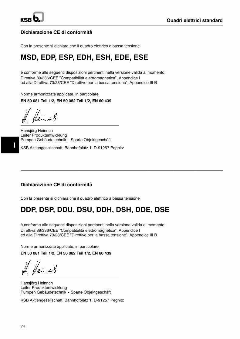
I
Quadri elettrici standard
74
Dichiarazione CE di conformità
Con la presente si dichiara che il quadro elettrico a bassa tensione
MSD, EDP, ESP, EDH, ESH, EDE, ESE
è conforme alle seguenti disposizioni pertinenti nella versione valida al momento:Direttiva 89/336/CEE �Compatibilità elettromagnetica�, Appendice Ied alla Direttiva 73/23/CEE �Direttive per la bassa tensione�, Appendice III B
Norme armonizzate applicate, in particolare
EN 50 081 Teil 1/2, EN 50 082 Teil 1/2, EN 60 439
Hansjörg HeinrichLeiter ProduktentwicklungPumpen Gebäudetechnik -- Sparte Objektgeschäft
KSB Aktiengesellschaft, Bahnhofplatz 1, D-91257 Pegnitz
____________________________________________________________________________________________
Dichiarazione CE di conformità
Con la presente si dichiara che il quadro elettrico a bassa tensione
DDP, DSP, DDU, DSU, DDH, DSH, DDE, DSE
è conforme alle seguenti disposizioni pertinenti nella versione valida al momento:Direttiva 89/336/CEE �Compatibilità elettromagnetica�, Appendice Ied alla Direttiva 73/23/CEE �Direttive per la bassa tensione�, Appendice III B
Norme armonizzate applicate, in particolare
EN 50 081 Teil 1/2, EN 50 082 Teil 1/2, EN 60 439
Hansjörg HeinrichLeiter ProduktentwicklungPumpen Gebäudetechnik -- Sparte Objektgeschäft
KSB Aktiengesellschaft, Bahnhofplatz 1, D-91257 Pegnitz
I
Attenzione
Quadri elettrici standard
75
1 GeneralitàQuesto apparecchio KSB è prodotto secondo la tecnicapiù aggiornata, viene costruito con grande cura ed è sog-getto a continui controlli qualitativi.Queste istruzioni di servizio devono facilitare la cono-scenza dell�apparecchio per sfruttare al meglio le suepossibilità di impiego per l�utilizzo previsto.Queste istruzioni forniscono indicazioni importanti per unfunzionamento sicuro, adeguato ed economico dell�ap-parecchio. E� necessario osservarle per assicurare l�affi-dabilità dell�apparecchio e la sua lunga durata ed evitarepericoli.Questo manuale non contempla le norme di sicurezzavalide localmente e per la cui osservanza, anche daparte del personale preposto al montaggio, è responsa-bile il committente.Questoapparecchionondeve venir fatto funzionareoltrei valori indicati nel foglio dati e riguardanti tensione diesercizio, frequenza nominale della rete, temperaturaambiente, potere di rottura, od in contrasto con altre dis-posizioni contenute nel manuale di istruzioni o nella do-cumentazione di vendità.Sulla targhetta sono indicati la serie costruttiva e la gran-dezza, i dati di esercizio principali ed il numero di matri-cola; questi dati devono sempre venir indicati per infor-mazioni ulteriori, per ordinazioni supplementari especialmente quando si ordinano ricambi.Qualora fosseronecessarie ulteriori informazioni od indi-cazioni, come pure nel caso di avarie, Vi preghiamo di ri-volgerVi al più vicino centro KSB di assistenza.
2 SicurezzaQuesto manuale racchiude direttive fondamentali chedevono venir rispettate durante le fasi di installazione,funzionamento e manutenzione. E� pertanto necessarioche questo manuale venga letto, prima del montaggio edella messa in marcia, dal montatore nonché dal perso-nale specializzato competente e dal gestore dell�im-pianto ed inoltre esso deve essere sempre a disposi-zione sul luogo di impiego della macchina.Non si devono osservare solamente le indicazioni di si-curezza di carattere generale esposte in questo capitolo,ma si devono osservare anche tutte le indicazioni spe-ciali di sicurezza inserite nei restanti capitoli.
2.1 Contrassegni delle indicazioni delmanualeLe indicazioni di sicurezza contenute in questomanuale,la cui mancata osservanza può costituire pericolo per lepersone, sono contrassegnate con il simbolo generico dipericolo
Segnale di sicurezza secondo DIN 4844 -- W9
nel caso di avvertimento contro la tensione elettrica sonocontrassegnate con
Segnale di sicurezza secondo DIN 4844 -- W8
Nel caso di indicazioni la cui mancata osservanza puòcostituire pericolo per l�appaerecchio e per il suo funzio-namento è inserita la parola
2.2 Qualifica ed addestramento delpersonale
Il personale di servizio, manutenzione, ispezione emon-taggio deve avere la qualifica adeguata per i lavori dasvolgere.Il gestore dell�impianto deve regolare con precisione re-sponsabilità, competenze e controllo del personale.Qualora il personale non avesse l�esperienza necessa-ria, esso deve venir addestrato ed istruito. A questo add-estramento può provvedere, se necessario, il costrut-tore/il fornitore su ordine del gestore dell�impianto. Ilgestore deve inoltre assicurarsi che il contenuto delman-uale venga capito completamente dal personale.
2.3 Pericoli nel caso di mancata osservanzadelle indicazioni di sicurezza
La mancata osservanza delle indicazioni di sicurezzapuò condurre come conseguenza a pericoli per le per-sone come pure per l�ambiente e per l�impianto. Laman-cata osservanza delle indicazioni di sicurezza comportala perdita di qualsivoglia diritto a risarcimento di danni.La mancata osservanza delle indicazioni può ad esem-pio comportare i pericoli seguenti:-- Mancato funzionamento di importanti funzioni dell�ap-parecchio
-- Difetto dei prescritti metodi per il controllo-- Pericoli per le persone a causa di influenze elettriche,meccaniche o chimiche.
2.4 Lavori con cognizione delle norme disicurezza
Si devono osservare le indicazioni di sicurezza espostenel presente manuale, le esistenti prescrizioni nazionaliinmateriadi prevenzionedegli infortuni nonchéeventualiprescrizioni interne dell�azienda in merito a lavoro, fun-zionamento e sicurezza.
2.5 Norme di sicurezza per chi gestiscel�impianto/per il personale di servizio
Si devono escludere pericoli dovuti all�energia elettrica(per dettagli in proposito vedi le prescrizioni locali e/odella locale società erogatrice di energia elettrica).
2.6 Indicazioni di sicurezza per lavori dimanutenzione, ispezione e montaggio
Il gestore deve curare che tutti i lavori di manutenzione,ispezione emontaggio vengano eseguiti da parte di per-sonale autorizzato e specializzato, che si sia informato asufficienza con uno studio approfondito del manuale.Per principio lavori all�apparecchio devono venir eseguitisolamente in assenza di tensione.Non appena ultimati i lavori si devono collegare nuova-mente o rimettere in funzione tutti i dispositivi di sicu-rezza e di protezione.Prima di rimettere in marcia si devono osservare i puntiesposti al capitolo �Prima messa in marcia�.
I
Quadri elettrici standard
76
2.7 Modifiche arbitrarie e costruzione diricambi
Modifiche o variazioni dell�apparecchio sono ammissibilisolamente in seguito ad intese con il costruttore.Ricambioriginali ed accessori autorizzati dal costruttore servonoper la sicurezza. Qualora venissero impiegate altre partisi escludono responsabilità per le conseguenze deri-vanti.
2.8 Modalità di funzionamento nonammissibili
La sicurezza di funzionamento dell�apparecchio fornito ègarantita solamente se esso viene impiegato per l�usoprevisto. I valori limite indicati nel foglio dati non devonoin alcun caso venir superati.
3 Trasporto/Immagazzinamento3.1 TrasportoL�apparecchio deve venir trasportato da parte di perso-nale esperto. Quadri verticali devono venir trasportati inposizioneorizzontale, perchéaltrimenti lapiastradimon-taggio si flette. Prima della spedizioni è stato controllatoche l�apparecchio corrisponda a tutti i dati indicati. Per-tantoall�arrivo l�apparecchiodovrebbe trovarsi inperfettecondizioni elettriche emeccaniche. Per sincerarsi di ciò,alla consegna dell�apparecchio consigliamo di control-lare che non abbia subito danni durante il trasporto. Incasodi reclami si devecompilareassiemeal portatoreunverbale di accertamento danni.
3.2 ImmagazzinamentoL�apparecchio deve venir immagazzinato all�asciutto, alriparo da urti e possibilmente nell�imballo originale.La temperatura ambiente non deve uscire dal campo--10 !C fino a +50 !C.
4 Descrizione4.1 Descrizione generaleLe descrizioni ed istruzioni del presente manuale riguar-dano l�esecuzione standard con quadri elettrici originaliKSB.I quadri elettrici standarddiKSBsonoquadri a bassa ten-sione secondo EN 60 439 per il comando e la protezionedi uno o duemotori monofase o trifase. Il motore od i mo-tori fino a 4 kW compreso vengono avviati direttamente(1~ e 3~) a partire da una potenza di 5,5 kW (solamente3~) vengono avviati in stella-triangolo.
4.2 DenominazioneQuadri elettrici standardLa denominazione dei quadri elettrici è composta da let-tere e cifre (eccezioni MSE/MSD vedi descrizione)
E/D D/S P/C/E/W/U/H -/X/L 40 .1
Comando singoloComando doppio
Avvamento direttoAvviamento stella-triangolo
Contatti non sotto tensioneCondensatore 1)Protezione Ex 2)Corrente monofaseOrologio (comandato in funzione del tempo)Hyamation (incremento della pressione)
�nessuna lettera� (standard)X esecuzione specialemisurazione della pressione di ristagno(principio a gorgogliamento d�aria)
Intensità massima della corrente x 10
Numero indice
Contrassegni ulteriori non hanno alcun effetto sulle funzionidescritte in questo manuale di istruzioni..Queste ulteriori denominazioni contraddistinguono ad es. ver-sioni nazionali specifiche per quanto riguarda il complessodell�equipaggiamento,ad es. Suffix EUserie interruttore principale e trasformatore di regolazionead es. Suffix FLSquadro per installazione all�aperto
1) Motore senza condensatore di esercizio. Il condensatore per ilmotore è montato nel quadro elettrico
2) Protezione Ex mediante un relé speciale. Il quadro di comandonon deve venir installato in ambienti soggetti a pericolo di es-plosione.
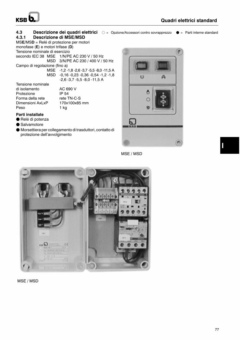
I
Quadri elettrici standard
77
4.3 Descrizione dei quadri elettrici f = Opzione/Accessori contro sovrapprezzo F = Parti interne standard
4.3.1 Descrizione di MSE/MSDMSE/MSD = Relé di protezione per motorimonofase (E) e motori trifase (D)Tensione nominale di eserciziosecondo IEC 38 MSE 1/N/PE AC 230 V / 50 Hz
MSD 3/N/PE AC 230 / 400 V / 50 HzCampo di regolazione (fino a)
MSE -1,2 -1,8 -2,6 -3,7 -5,5 -8,0 -11,5 AMSD -0,16 -0,23 -0,36 -0,54 -1,2 -1,8
-2,6 -3,7 -5,5 -8,0 -11,5 ATensione nominaledi isolamento AC 690 VProtezione IP 54Forma della rete rete TN-C-SDimensioni AxLxP 170x100x85 mmPeso 1 kg
Parti installateFRelé di potenzaF SalvamotoreFMorsettiera per collegamento di trasduttori, contatto diprotezione dell�avvolgimento
MSE / MSD
MSE / MSD
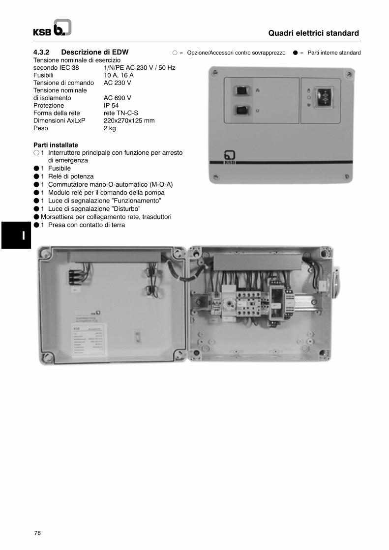
I
Quadri elettrici standard
78
4.3.2 Descrizione di EDW f = Opzione/Accessori contro sovrapprezzo F = Parti interne standardTensione nominale di eserciziosecondo IEC 38 1/N/PE AC 230 V / 50 HzFusibili 10 A, 16 ATensione di comando AC 230 VTensione nominaledi isolamento AC 690 VProtezione IP 54Forma della rete rete TN-C-SDimensioni AxLxP 220x270x125 mmPeso 2 kg
Parti installatef 1 Interruttore principale con funzione per arresto
di emergenzaF 1 FusibileF 1 Relé di potenzaF 1 Commutatore mano-O-automatico (M-O-A)F 1 Modulo relé per il comando della pompaF 1 Luce di segnalazione �Funzionamento�F 1 Luce di segnalazione �Disturbo�FMorsettiera per collegamento rete, trasduttoriF 1 Presa con contatto di terra
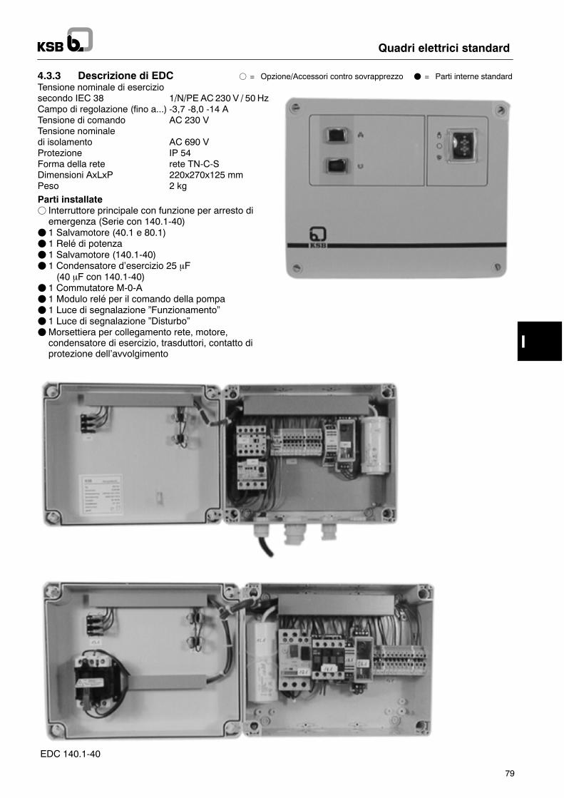
I
Quadri elettrici standard
79
4.3.3 Descrizione di EDC f = Opzione/Accessori contro sovrapprezzo F = Parti interne standardTensione nominale di eserciziosecondo IEC 38 1/N/PE AC 230 V / 50 HzCampo di regolazione (fino a...) -3,7 -8,0 -14 ATensione di comando AC 230 VTensione nominaledi isolamento AC 690 VProtezione IP 54Forma della rete rete TN-C-SDimensioni AxLxP 220x270x125 mmPeso 2 kg
Parti installatef Interruttore principale con funzione per arresto diemergenza (Serie con 140.1-40)
F 1 Salvamotore (40.1 e 80.1)F 1 Relé di potenzaF 1 Salvamotore (140.1-40)F 1 Condensatore d�esercizio 25 mF1 (40 mF con 140.1-40)
F 1 Commutatore M-0-AF 1 Modulo relé per il comando della pompaF 1 Luce di segnalazione �Funzionamento�F 1 Luce di segnalazione �Disturbo�FMorsettiera per collegamento rete, motore,condensatore di esercizio, trasduttori, contatto diprotezione dell�avvolgimento
EDC
EDC 140.1-40
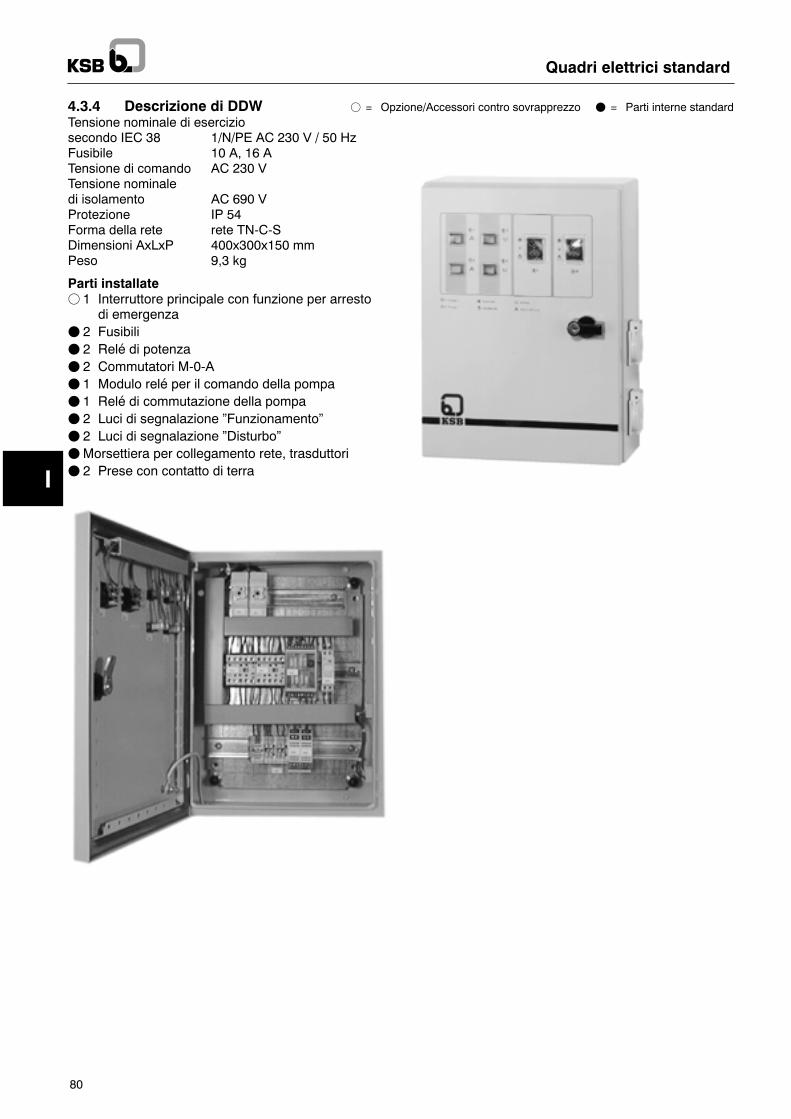
I
Quadri elettrici standard
80
4.3.4 Descrizione di DDW f = Opzione/Accessori contro sovrapprezzo F = Parti interne standardTensione nominale di eserciziosecondo IEC 38 1/N/PE AC 230 V / 50 HzFusibile 10 A, 16 ATensione di comando AC 230 VTensione nominaledi isolamento AC 690 VProtezione IP 54Forma della rete rete TN-C-SDimensioni AxLxP 400x300x150 mmPeso 9,3 kg
Parti installatef 1 Interruttore principale con funzione per arresto
di emergenzaF 2 FusibiliF 2 Relé di potenzaF 2 Commutatori M-0-AF 1 Modulo relé per il comando della pompaF 1 Relé di commutazione della pompaF 2 Luci di segnalazione �Funzionamento�F 2 Luci di segnalazione �Disturbo�FMorsettiera per collegamento rete, trasduttoriF 2 Prese con contatto di terra
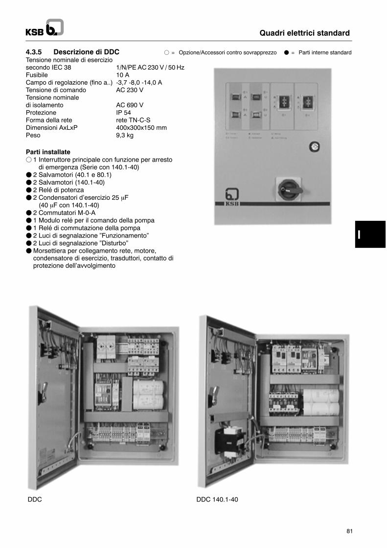
I
Quadri elettrici standard
81
4.3.5 Descrizione di DDC f = Opzione/Accessori contro sovrapprezzo F = Parti interne standardTensione nominale di eserciziosecondo IEC 38 1/N/PE AC 230 V / 50 HzFusibile 10 ACampo di regolazione (fino a..) -3,7 -8,0 -14,0 ATensione di comando AC 230 VTensione nominaledi isolamento AC 690 VProtezione IP 54Forma della rete rete TN-C-SDimensioni AxLxP 400x300x150 mmPeso 9,3 kg
Parti installatef 1 Interruttore principale con funzione per arresto1 di emergenza (Serie con 140.1-40)
F 2 Salvamotori (40.1 e 80.1)F 2 Salvamotori (140.1-40)F 2 Relé di potenzaF 2 Condensatori d�esercizio 25 mF1 (40 mF con 140.1-40)
F 2 Commutatori M-0-AF 1 Modulo relé per il comando della pompaF 1 Relé di commutazione della pompaF 2 Luci di segnalazione �Funzionamento�F 2 Luci di segnalazione �Disturbo�FMorsettiera per collegamento rete, motore,condensatore di esercizio, trasduttori, contatto diprotezione dell�avvolgimento
DDC DDC 140.1-40
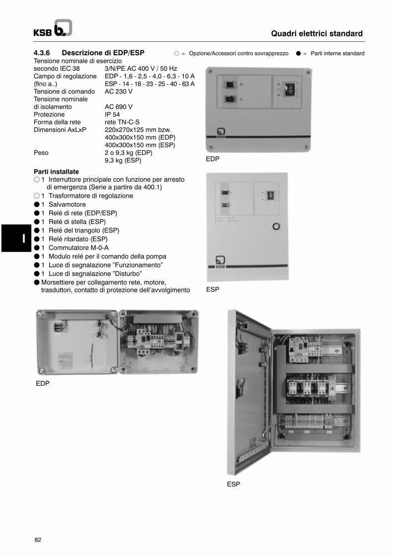
I
Quadri elettrici standard
82
4.3.6 Descrizione di EDP/ESP f = Opzione/Accessori contro sovrapprezzo F = Parti interne standardTensione nominale di eserciziosecondo IEC 38 3/N/PE AC 400 V / 50 HzCampo di regolazione EDP - 1,6 - 2,5 - 4,0 - 6,3 - 10 A(fino a..) ESP - 14 - 18 - 23 - 25 - 40 - 63 ATensione di comando AC 230 VTensione nominaledi isolamento AC 690 VProtezione IP 54Forma della rete rete TN-C-SDimensioni AxLxP 220x270x125 mm bzw.
400x300x150 mm (EDP)400x300x150 mm (ESP)
Peso 2 o 9,3 kg (EDP)9,3 kg (ESP)
Parti installatef 1 Interruttore principale con funzione per arresto0 di emergenza (Serie a partire da 400.1)
f 1 Trasformatore di regolazioneF 1 SalvamotoreF 1 Relé di rete (EDP/ESP)F 1 Relé di stella (ESP)F 1 Relé del triangolo (ESP)F 1 Relé ritardato (ESP)F 1 Commutatore M-0-AF 1 Modulo relé per il comando della pompaF 1 Luce di segnalazione �Funzionamento�F 1 Luce di segnalazione �Disturbo�FMorsettiere per collegamento rete, motore,trasduttori, contatto di protezione dell�avvolgimento
EDP
ESP
EDP
ESP
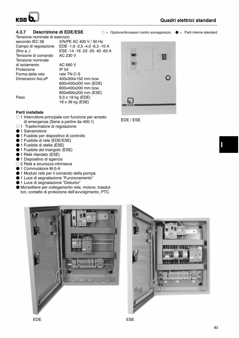
I
Quadri elettrici standard
83
4.3.7 Descrizione di EDE/ESE f = Opzione/Accessori contro sovrapprezzo F = Parti interne standardTensione nominale di eserciziosecondo IEC 38 3/N/PE AC 400 V / 50 HzCampo di regolazione EDE -1,6 -2,5 -4,0 -6,3 -10 A(fino a..) ESE -14 -18 -23 -25 -40 -63 ATensione di comando AC 230 VTensione nominaledi isolamento AC 690 VProtezione IP 54Forma della rete rete TN-C-SDimensioni AxLxP 400x300x150 mm bzw.
600x400x200 mm (EDE)600x400x200 mm bzw.800x600x200 mm (ESE)
Peso 9,3 o 18 kg (EDE)18 o 36 kg (ESE)
Parti installatef 1 Interruttore principale con funzione per arresto0 di emergenza (Serie a partire da 400.1)
f 1 Trasformatore di regolazioneF 1 SalvamotoreF 1 Fusibile per dispositivo di controlloF 1 Fusibile di rete (EDE/ESE)F 1 Fusibile di stella (ESE)F 1 Fusibile del triangolo (ESE)F 1 Relé ritardato (ESE)F 1 Dispositivo di sganciof 2 Relé a sicurezza intrinsecaF 1 Commutatore M-0-AF 1 Modulo relé per il comando della pompaF 1 Luce di segnalazione �Funzionamento�F 1 Luce di segnalazione �Disturbo�FMorsettiere per collegamento rete, motore, trasdut-tori, contatto di protezione dell�avvolgimento, PTC
EDE / ESE
ESEEDE
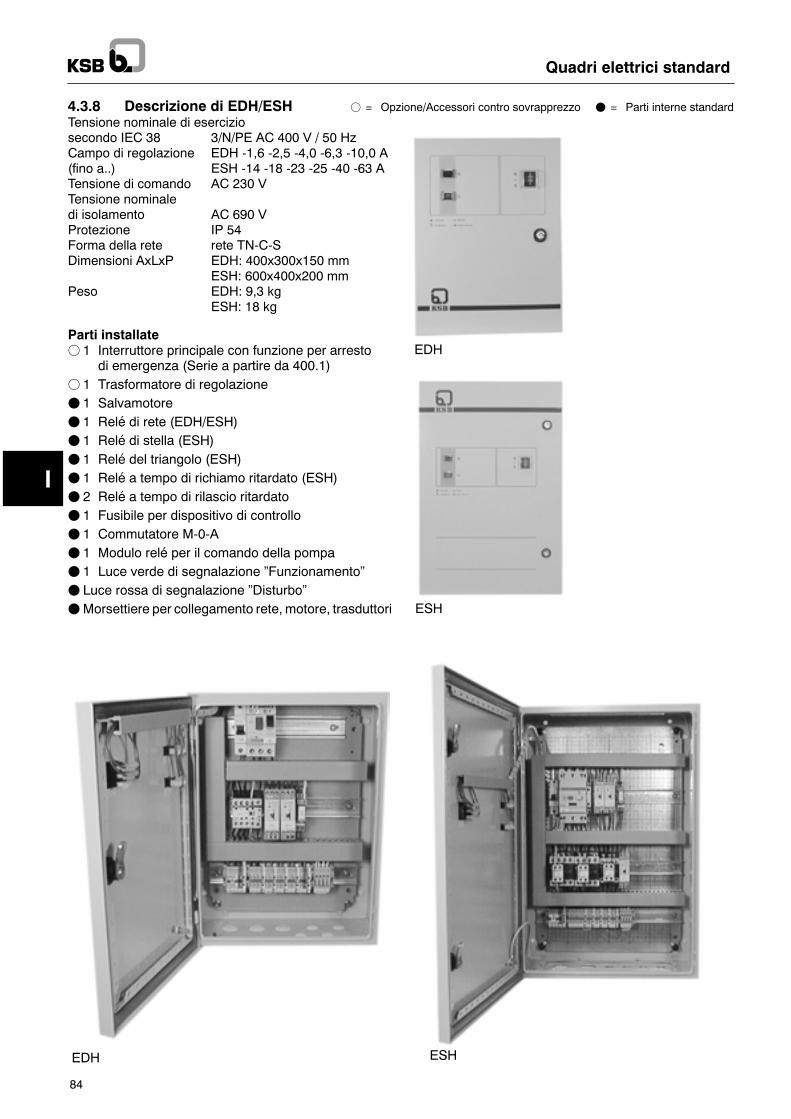
I
Quadri elettrici standard
84
4.3.8 Descrizione di EDH/ESH f = Opzione/Accessori contro sovrapprezzo F = Parti interne standardTensione nominale di eserciziosecondo IEC 38 3/N/PE AC 400 V / 50 HzCampo di regolazione EDH -1,6 -2,5 -4,0 -6,3 -10,0 A(fino a..) ESH -14 -18 -23 -25 -40 -63 ATensione di comando AC 230 VTensione nominaledi isolamento AC 690 VProtezione IP 54Forma della rete rete TN-C-SDimensioni AxLxP EDH: 400x300x150 mm
ESH: 600x400x200 mmPeso EDH: 9,3 kg
ESH: 18 kg
Parti installatef 1 Interruttore principale con funzione per arresto
di emergenza (Serie a partire da 400.1)f 1 Trasformatore di regolazioneF 1 SalvamotoreF 1 Relé di rete (EDH/ESH)F 1 Relé di stella (ESH)F 1 Relé del triangolo (ESH)F 1 Relé a tempo di richiamo ritardato (ESH)F 2 Relé a tempo di rilascio ritardatoF 1 Fusibile per dispositivo di controlloF 1 Commutatore M-0-AF 1 Modulo relé per il comando della pompaF 1 Luce verde di segnalazione �Funzionamento�F Luce rossa di segnalazione �Disturbo�FMorsettiere per collegamento rete, motore, trasduttori
EDH
ESH
EDH ESH
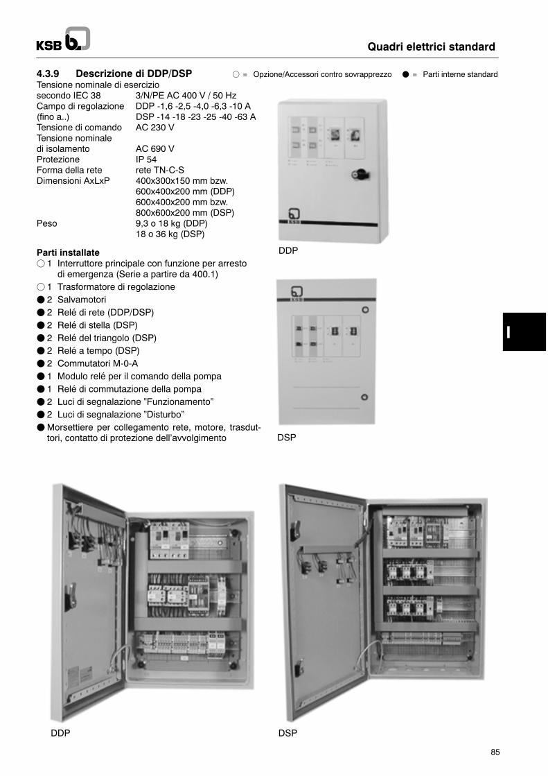
I
Quadri elettrici standard
85
4.3.9 Descrizione di DDP/DSP f = Opzione/Accessori contro sovrapprezzo F = Parti interne standardTensione nominale di eserciziosecondo IEC 38 3/N/PE AC 400 V / 50 HzCampo di regolazione DDP -1,6 -2,5 -4,0 -6,3 -10 A(fino a..) DSP -14 -18 -23 -25 -40 -63 ATensione di comando AC 230 VTensione nominaledi isolamento AC 690 VProtezione IP 54Forma della rete rete TN-C-SDimensioni AxLxP 400x300x150 mm bzw.
600x400x200 mm (DDP)600x400x200 mm bzw.800x600x200 mm (DSP)
Peso 9,3 o 18 kg (DDP)18 o 36 kg (DSP)
Parti installatef 1 Interruttore principale con funzione per arresto
di emergenza (Serie a partire da 400.1)f 1 Trasformatore di regolazioneF 2 SalvamotoriF 2 Relé di rete (DDP/DSP)F 2 Relé di stella (DSP)F 2 Relé del triangolo (DSP)F 2 Relé a tempo (DSP)F 2 Commutatori M-0-AF 1 Modulo relé per il comando della pompaF 1 Relé di commutazione della pompaF 2 Luci di segnalazione �Funzionamento�F 2 Luci di segnalazione �Disturbo�FMorsettiere per collegamento rete, motore, trasdut-tori, contatto di protezione dell�avvolgimento
DDP
DSP
DDP DSP
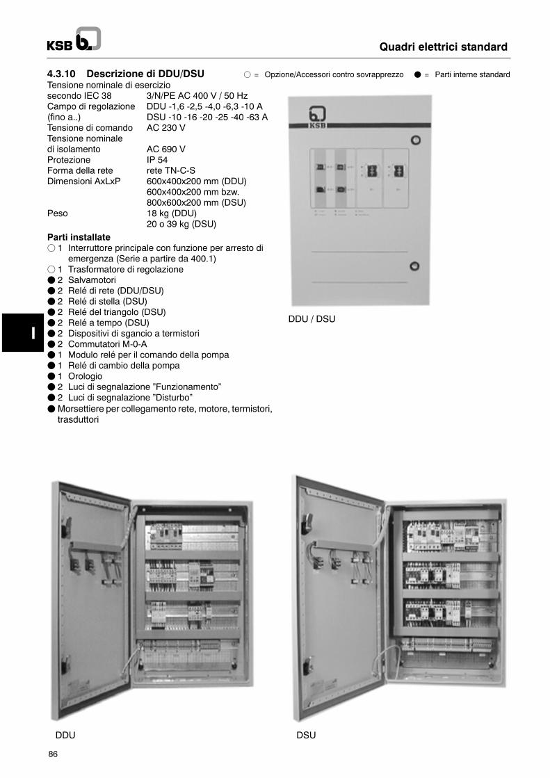
I
Quadri elettrici standard
86
4.3.10 Descrizione di DDU/DSU f = Opzione/Accessori contro sovrapprezzo F = Parti interne standardTensione nominale di eserciziosecondo IEC 38 3/N/PE AC 400 V / 50 HzCampo di regolazione DDU -1,6 -2,5 -4,0 -6,3 -10 A(fino a..) DSU -10 -16 -20 -25 -40 -63 ATensione di comando AC 230 VTensione nominaledi isolamento AC 690 VProtezione IP 54Forma della rete rete TN-C-SDimensioni AxLxP 600x400x200 mm (DDU)
600x400x200 mm bzw.800x600x200 mm (DSU)
Peso 18 kg (DDU)20 o 39 kg (DSU)
Parti installatef 1 Interruttore principale con funzione per arresto di
emergenza (Serie a partire da 400.1)f 1 Trasformatore di regolazioneF 2 SalvamotoriF 2 Relé di rete (DDU/DSU)F 2 Relé di stella (DSU)F 2 Relé del triangolo (DSU)F 2 Relé a tempo (DSU)F 2 Dispositivi di sgancio a termistoriF 2 Commutatori M-0-AF 1 Modulo relé per il comando della pompaF 1 Relé di cambio della pompaF 1 OrologioF 2 Luci di segnalazione �Funzionamento�F 2 Luci di segnalazione �Disturbo�FMorsettiere per collegamento rete, motore, termistori,trasduttori
DDU / DSU
fehltDDU folgt neuvon BOE
DDU DSU
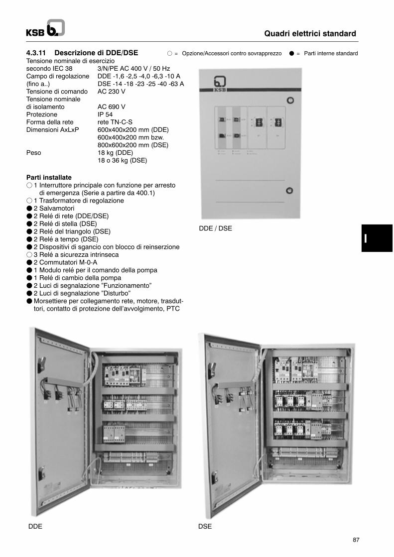
I
Quadri elettrici standard
87
4.3.11 Descrizione di DDE/DSE f = Opzione/Accessori contro sovrapprezzo F = Parti interne standardTensione nominale di eserciziosecondo IEC 38 3/N/PE AC 400 V / 50 HzCampo di regolazione DDE -1,6 -2,5 -4,0 -6,3 -10 A(fino a..) DSE -14 -18 -23 -25 -40 -63 ATensione di comando AC 230 VTensione nominaledi isolamento AC 690 VProtezione IP 54Forma della rete rete TN-C-SDimensioni AxLxP 600x400x200 mm (DDE)
600x400x200 mm bzw.800x600x200 mm (DSE)
Peso 18 kg (DDE)18 o 36 kg (DSE)
Parti installatef 1 Interruttore principale con funzione per arresto0 di emergenza (Serie a partire da 400.1)
f 1 Trasformatore di regolazioneF 2 SalvamotoriF 2 Relé di rete (DDE/DSE)F 2 Relé di stella (DSE)F 2 Relé del triangolo (DSE)F 2 Relé a tempo (DSE)F 2 Dispositivi di sgancio con blocco di reinserzionef 3 Relé a sicurezza intrinsecaF 2 Commutatori M-0-AF 1 Modulo relé per il comando della pompaF 1 Relé di cambio della pompaF 2 Luci di segnalazione �Funzionamento�F 2 Luci di segnalazione �Disturbo�FMorsettiere per collegamento rete, motore, trasdut-tori, contatto di protezione dell�avvolgimento, PTC
DDE / DSE
DDE DSE
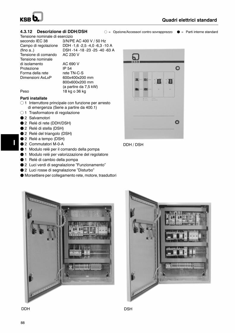
I
Quadri elettrici standard
88
4.3.12 Descrizione di DDH/DSH f = Opzione/Accessori contro sovrapprezzo F = Parti interne standardTensione nominale di eserciziosecondo IEC 38 3/N/PE AC 400 V / 50 HzCampo di regolazione DDH -1,6 -2,5 -4,0 -6,3 -10 A(fino a..) DSH -14 -18 -23 -25 -40 -63 ATensione di comando AC 230 VTensione nominaledi isolamento AC 690 VProtezione IP 54Forma della rete rete TN-C-SDimensioni AxLxP 600x400x200 mm
800x600x200 mm(a partire da 7,5 kW)
Peso 18 kg o 36 kg
Parti installatef 1 Interruttore principale con funzione per arresto0 di emergenza (Serie a partire da 400.1)
f 1 Trasformatore di regolazioneF 2 SalvamotoriF 2 Relé di rete (DDH/DSH)F 2 Relé di stella (DSH)F 2 Relé del triangolo (DSH)F 2 Relé a tempo (DSH)F 2 Commutatori M-0-AF 1 Modulo relé per il comando della pompaF 1 Modulo relé per valorizzazione del regolatoreF 1 Relé di cambio della pompaF 2 Luci verdi di segnalazione �Funzionamento�F 2 Luci rosse di segnalazione �Disturbo�FMorsettiere per collegamento rete, motore, trasduttori
DDH / DSH
DDH DSH
I
Attenzione
Quadri elettrici standard
89
4.4 Opzioni-- Contatore delle ore di funzionamento-- Amperometro-- Interruttore principale (componente standard a partireda 400.1 e 630.1)
-- Voltmetro-- Attacco per termistori con dispositivo di sgancio (com-ponente standard a partire da 400.1 e DDU/DSU)
-- Relé di controllo (successione delle fasi/caduta di unafase, sovratensione/sottotensione)
-- Opzioni ulteriori a richiesta.
5 Installazione5.1 Condizioni ambientali-- asciutto ed al riparo dal gelo-- ventilazione sufficiente-- possibilità di chiudere, l�accesso di personale non au-torizzato non è ammissibile
Il quadro elettrico deve venir installato al sicuro da traci-mazioni d�acqua.I quadri elettrici non sono in esecuzione antideflagrantee devono pertanto venir fatti funzionare solamente fuorida ambienti con pericolo di esplosione.
5.2 Collegamento elettricoF Al collegamento elettrico deve provvedere solamentepersonale esperto.
F Si devono osservare le condizioni per gli allacciamentielettrici della locale Società di distribuzione dell�ener-gia elettrica.
FControllare il tipo della corrente e la tensione degli at-tacchi alla rete.
FOsservare i collegamenti del motore dello schemaelettrico.
F Tarare il salvamotore alla corrente nominale.
FDimensionamento del cavo elettrico di collegamentosecondo DIN VDE 0100, parte 430.
FOsservare la protezione massima con fusibili in con-formità allo schema elettrico.
Il cavo di alimentazione posato in cantiere nel caso dimotori trifase deve venir collegato come campo di rota-zione destrorso. Nel caso di motori monofase si deve farattenzione che fase e neutro vengano collegati corretta-mente.Si devono collegare solamente pompe KSB i cui datitecnici corrispondano con questa combinazione diquadro elettrico.Altri apparecchi non devono in alcun caso venir col-legati, perchè possono provocare disturbi che dan-neggiano il quadro elettrico.Si devono osservare i collegamenti dello schema elet-trico.FOsservare la regolazione dell�interruttore a galleg-giante in conformità alle indicazioni dello schemaelet-trico.
F Il contatto di protezione dell�avvolgimento deve venircollegato con i fili corrispondenti del cavodella pompa.
Nel caso di pompe senza contatto di protezione dell�av-volgimento si deve inserire un ponte nel quadro elettrico.
6 Messa in marcia/Arresto6.1 GeneralitàAlla messa in marcia si può provvedere solamente se lepertinenti prescrizioni VDE sono state soddisfatte.Prima della messa in funzione del quadro elettrico si de-vono controllare i punti seguenti:-- Cavo della pompa collegato-- Protezione contro la temperatura (contatto di prote-zione dell�avvolgimento) collegata.
-- Cavo di alimentazione collegato correttamente(campo di rotazione destrorso con motori trifase)
-- Trasduttore (interruttore a galleggiante, pressostato,contatore) collegato e tarato. In proposito si devonoosservare i paragrafi 6.2.1 fino a 6.2.4.
Solamente quandoquesti lavori saranno stati eseguiti daparte di un elettricista esperto, si potrà provvedere allamessa in servizio del quadro elettrico.Per l�esecuzionedi questi lavori si devonoosservarei collegamenti previsti dallo schema elettrico non-ché le istruzioni di funzionamento della pompa.
6.2 Avviamento
I lavori seguenti devono venir generalmente eseguiti.Osservare le istruzioni dei paragrafi 6.2.1 fino a 6.2.4.-- Mettere l�interruttore principale su �0�.-- Porre il commutatore M-O-A (mano-zero-automatico)sulla posizione �0�.
-- Confrontare il valore di taratura del salvamotore con lacorrente nominale del motore e, se necessario, cor-reggere la taratura.
-- Porre il salvamotore sulla posizione �I�.-- Il relé a tempo per la commutazione da stella a trian-golo è tarato in fabbrica a 3 secondi ed eventualmentedeve venir adattato.
-- Alimentare elettricamente. Per questo la protezione diimpianto (ad es. interruttore automatico) deve venirposta su �I�.
-- Qualora fosse previsto l�interruttore principale, porrequesto su �I�.
-- Nel caso di motori trifase, controllare il senso di rota-zione. Per questo l�interruttore M-O-A deve venir bre-vemente posto su �Mano� -- solamente con livello su-periore a quello di arresto o pressione inferiore aquella di arresto--.Si devono osservare le istruzioni di funzionamentodella pompa/del sistema.
6.2.1 Comando singolo o doppio in funzionedel livello
L�avviamento e l�arresto della pompa (delle pompe) av-viene tramite un (due) galleggiante (i), trasduttore di li-vello od interruttore magnetico.Il livello di intervento deve venir regolato sull�impianto.A questa regolazione si provvede scegliendoopportuna-mente l�altezza alla quale il cavo dell�interruttore agalleggiante va fissato alla tubazione premente,all�impugnatura o ad un punto adeguato, nonché lalunghezza libera di cavo dell�interruttore a galleggiante.Questa lunghezza non deve essere inferiore a 10 cmdalbeccuccio di protezione del punto di flessione, perpermettere un funzionamento perfetto dell�interruttore agalleggiante anche con cavo freddo rigido. L�avviamento
I
Quadri elettrici standard
90
avviene quando il corpo del galleggiante è inclinato dicirca 30! verso l�alto, l�arresto con una posizione di circa30 ! verso il basso (si ode distintamente il rumore dellacommutazione nel corpo del galleggiante), differenzaminima fra i due interventi circa 40 cm. Regolando i puntidi intervento si deve far attenzione che la pompa vengafermata prima che il livello del liquido raggiunga leaperture di aspirazione del piede della pompa.L�avviamentodeveavvenire primache il livello del liquidoraggiunga il bordo del pozzetto.L�interruttore a galleggiante non deve appoggiare inbassonéurtarecontro l�eventualecoperturadelpozzettoin alto. Si deve pure far attenzione che il galleggiante nonresti impigliato a sporgenze o simili.
Nel caso di installazione di 2 pompe ed impiego di uncomandodoppio, i due galleggianti devono venir dispostiin cascata. Ne derivano 3 funzioni di comando:1. Avviamento alternato delle due pompe ad ognimessain marcia.
2. Inserzione della pompa ferma nel caso di carico dipunta.
3.Inserzione della pompa ferma nel caso di disturbo.
6.2.2 Comando singolo in funzione dellapressione
L�avviamento e l�arresto vengono comandati da un pres-sostato montato nella tubazione premente.Questopressostatoper quanto riguardaqualità e tecnicadeve essere adeguato al liquido convogliato.Il pressostato viene tarato in base alle istruzioni ad essoallegate. Con una taratura a regola d�arte ed adeguataall�idraulica, il relé a tempo abbinato al pressostato (vedischema elettrico) evita uno sfarfallamento dell�impianto.Conseguentemente con piccoli prelievi di liquido ven-gono evitati continui avviamenti ed arresti. La regola-zione del tempo si effettua in sito.Sul lato aspirante mediante un interruttore a galleg-giante, un pressostato od un elettrodo (opzione) vieneevitato il funzionamento a secco della pompa.Un relé a tempo oppure un relé ad elettrodi impedisceuno sfarfallamento dell�impianto nel casodi unabrevedi-minuzione del livello o della pressione. Il tempo di ritardodeve essere adeguato all�impianto.L�interruttore a galleggiante deve venir fissato ad unpunto adatto in modo che sia libero di muoversi e che alraggiungimento del livello minimo dell�acqua la pompavenga fermata con sicurezza. Il corpo del galleggiantenon deve assolutamente urtare contro il fondo o controil coperchio del serbatoio.Gli elettrodi devono venir montati nel modo seguente nelserbatoio:In conformità alle istruzioni collegare l�elettrodo con ilcavo relativo. Calare l�elettrodo di massa fino sul fondodel serbatoio. Esso deve però poter ancora oscillare li-beramente.Il secondo elettrodo viene appeso con la sua parte infer-iore sopra il fondoadunadistanza tale come richiesto dallivello minimo ammissibile dell�acqua.
Il pressostato viene tarato, in base alle istruzioni ad essoallegate, alla pressione minima ammissibile gravantesull�ingresso.
6.2.3 Comando doppio in funzione deltempo
Il comando doppio è equipaggiato con diverse funzioni,che possono venir attivate dall�esterno tramite contattinon sotto tensione.-- sbloccoesterno -- in conformitàallo schemaelettricosideve rimuovere il ponticello, quindi si può collegare ilcontatto non sotto tensione.
-- carico di punta esterno -- mediante contatto non sottotensione.
-- cambio della pompa esterno -- l�interruttore sul relé dicomando della pompa deve venir commutato da �in-terno� a �esterno�. In conformità allo schema elettricocollegare un commutatore non sotto tensione senzaposizione zero. Le pompe possono così venir cam-biate tramite questo contatto.
I contatti di comando per le diverse funzioniesterne devono venir dimensionati per230 V/50 Hz, min. 1 Aind..
Con l�interruttore ad orologeria incorporato il cambiodella pompa può venir comandato internamente. Essodeve venir programmato dopo aver dato corrente. Anzi-tutto si deve programmare il tempo attuale ed il giornodella settimana. Quindi possono venir programmati itempi di commutazione. Il procedimento necessario èspiegato nelle istruzioni dell�orologio e sono diverse dacostruttore a costruttore.
6.2.4 Comando doppio in funzione dellapressione
L�avviamento e l�arresto delle pompe viene comandatoda un regolatore a tre punti montato nella tubazione pre-mente.Questo regolatore per quanto riguarda qualità e tecnicadeve essere adeguato al liquido convogliato.Il regolatore viene tarato in base alle istruzioni ad essoallegate.I relé a tempo �Tempo di attesa� e �Carico di punta� (vedischema elettrico) vengono tarati in fabbrica ed impedis-cono uno sfarfallamento dell�impianto.Nel caso di condizioni sfavorevoli di impianto questitempi devono eventualmente venir cambiati. Il nuovotempo regolato deve venir indicato nello schema elet-trico.Sul lato aspirante mediante un interruttore a galleg-giante, un pressostato od un elettrodo (opzione) vieneevitato il funzionamento a secco della pompa..Un relé a tempo oppure un relé ad elettrodi impedisceuno sfarfallamento dell�impianto nel casodi unabrevedi-minuzione del livello o della pressione. Il tempo di ritardodeve essere adeguato all�impianto.L�interruttore a galleggiante deve venir fissato ad unpunto adatto in modo che sia libero di muoversi e che alraggiungimento del livello minimo dell�acqua la pompavenga fermata con sicurezza. Il corpo del galleggiante
I
Quadri elettrici standard
91
non deve assolutamente urtare contro il fondo o controil coperchio del serbatoio.Gli elettrodi devono venir montati nel modo seguente nelserbatoio:In conformità alle istruzioni collegare l�elettrodo con ilcavo relativo. Calare l�elettrodo di massa fino sul fondodel serbatoio. Esso deve però poter ancora oscillare li-beramente.Il secondo elettrodo viene appeso con la sua parte infe-riore sopra il fondo ad una distanza tale come richiestodal livello minimo ammissibile dell�acqua.Il pressostato viene tarato, in base alle istruzioni ad essoallegate, alla pressione minima ammissibile gravantesull�ingresso.
6.3 Descrizione del funzionamento delcomando singolo
6.3.1 Funzionamento automatico concomando di livello
Il motore viene avviato e fermato con un interruttore a treposizioni (mano-0-automatico).Posizione �0�: Il motore è fermoPosizione �automatico�: Il motore viene avviato e fer-
mato da un trasduttore esterno.Posizione �mano�: Con l�interruttore su posizione
�mano� il motore può venir av-viato manualmente.
Svuotamento di un serbatoio/di una fossa; il trasduttorechiude con interruttore a galleggiante flottante.La pompa viene avviata e fermata in funzione del livello.Se il liquido da convogliare raggiunge il livello di inter-vento dell�interruttore a galleggiante, la pompa vienemessa in marcia. Il liquido viene pompato fino al livello diarresto dell�interruttore a galleggiante.Con interruttore sulla posizione �mano� la pompapuòve-nir avviata a mano. In proposito però si può provvederesolamente quando il livello è superiore a quello di ar-resto e solamente per un breve perioro di funziona-mento, come ad esempio per il controllo del senso di ro-tazione.Altrimenti allamessa inmarcia dell�impianto l�interruttoredeve sempre venir posizionato su �automatico�.
6.3.2 Funzionamento automatico coninserimento in funzione dellapressione
Il motore viene avviato e fermato con un interruttore a treposizioni (mano-0-automatico).Posizione �0�: Il motore è fermoPosizione �automatico�: Il motore viene avviato e fer-
mato da un trasduttore esterno.Posizione �mano�: Con l�interruttore su posizione
�mano� il motore può venir av-viato manualmente.
La pompa viene avviata quando la pressione dell�im-pianto è inferiore al valore di taratura del pressostato.Mediante un relé a tempo viene garantito un tempominimo di funzionamento. Il relé a tempo può venir rego-lato in funzione delle condizioni dell�impianto. L�arrestodella pompa avviene con ritardo dopo aver raggiunto lapressione di arresto per la quale il pressostato è tarato.
Unpressostato nella tubazionedi presa controlla la pres-sione gravante sull�aspirazione della pompa. Un relé atempo abbinato, che può venir tarato individualmente,durante la fase di avviamento evita uno sfarfallamento diavviamenti nel caso di una breve diminuzione di pres-sione. L�impianto viene fermato dal pressostato sola-mente se entro il tempo regolato non viene raggiunta lapressione minima nella tubazione di presa della pompa.La lucedi segnalazioneper lamancanzad�acqua (rossa)segnala che nella tubazione di alimentazione dellapompa non c�è acqua oppure che la pressione gravantesull�aspirazione della pompa non è sufficiente.Il riavviamento avviene automaticamente quando lapressioneminima sull�aspirazione della pompa è nuova-mente disponibile. La luce di segnalazione di disturbo(rossa) segnala se il salvamotore ha sganciato.In caso di arresto dell�intero automatismo è comunquepossibile eseguire l�avviamento a mano. Per questo l�in-terruttore deve venir commutato su �mano�.
6.4 Descrizione del funzionamento delcomando doppio
6.4.1 Funzionamento automatico coninserzione in funzione del livello
Il motore viene avviato e fermato con un interruttore a treposizioni (mano-0-automatico). Per ogni comandoèpre-visto un interruttore.Posizione �0�: Il motore è fermoPosizione �automatico�: Il motore viene avviato e fer-
mato da un trasduttore esterno.Se entrambi gli interruttori sonosu �automatico�, dopo ogni in-tervento vengono alternati inesercizio i motori di comando.Se unmotore va in avaria vieneimmediatamente commutatosul secondo motore.
Posizione �mano�: Con l�interruttore su posizione�mano� il motore può venir av-viato manualmente.
Svuotamento di un serbatoio/di una fossa; il trasduttorechiude con interruttore a galleggiante flottante.Le pompe vengono alternativamente avviate e fermatein funzione del livello. Se necessario vien avviata auto-maticamente la pompa per carico di punta. Se il liquidoda convogliare raggiunge il livello di intervento dell�inter-ruttore a galleggiante 1 (livello inferiore), viene messa inmarcia una pompa. Il liquido viene pompato fino al livellodi arresto dell�interruttore a galleggiante 1.Dopo un nuovo afflusso di liquido viene raggiunto nuova-mente il livello di intervento dell�interruttore a galleg-giante 1, a questo punto viene messa in marcia la se-conda pompa che al raggiungimento del livello di arrestoviene fermata nuovamente. Questa commutazione av-viene dopo ogni fermata.Se nonostante che una pompa si trovi in marcia il liquidoraggiungesse l�interruttore a galleggiante 2 (livello supe-riore), viene aggiunta in servizio la seconda pompa (ca-rico di punta).
I
Quadri elettrici standard
92
Nel caso di arresto di una pompa in seguito all�interventodel termointerruttore (contatto di protezione dell�avvolgi-mento), del termistore (PTC) o del salvamotore avvieneimmediatamente la commutazionesulla secondapompa(riserva).Con interruttore sulla posizione �mano� ogni pompa puòvenir avviata direttamente, in proposito però si può prov-vedere solamente quando il livello è superiore a quello diarresto e per un breve periodo di funzionamento, comead es. per il controllo del senso di rotazione.Altimenti alla messa in marcia l�interruttore deve semprevenir posizionato su �automatico�.
6.4.2 Funzionamento automatico coninserzione in funzione del tempo
Il motore viene avviato e fermato con un interruttore a treposizioni (mano-0-automatico). Per ogni comandoèpre-visto un interruttore.Posizione �0�: Il motore è fermoPosizione �automatico�: Se entrambi gli interruttori sono
su �automatico�, i motori dicomando vengono alternativa-mente avviati e fermati, in fun-zione del tempo, da un orolo-gio. Se un motore va in avariaviene immediatamente com-mutato sul secondo motore.
Posizione �mano�: Con l�interruttore su posizione�mano� il motore può venir av-viato manualmente.
Se gli interruttori mano-0-automatico (M-0-A) si trovanosulla posizione automatico, le pompe vengono cambiatein funzione dei tempi di commutazione programmatinell�orologio digitale. Questa commutazione da pompa 1a pompa 2, se prevista, può venir eseguita anche tramitecontatto esterno. Ciò è però possibile solamente se ilcommutatore sul quadro di comando è posizionato su�Esterno�.Mediante un contatto esterno per carico di punta può ve-nir avviata, se necessario, la pompa per carico di punta.Se il contatto esterno di sblocco viene interrotto, lapompe non possono venir avviate né automaticamentené a mano.Qualora durante il funzionamento di una pompa questadovesse andare in avaria, viene commutato automatica-mente sulla seconda pompa.Con posizione dell�interruttore su �mano� ogni pompapuò venir avviata direttamente. Questo è necessario ades. per il controllo del senso di rotazione. Se entrambi gliinterruttori M-0-A si trovano su �mano�, si può realizzareun avviamento interno per carico di punta. Altrimenti allamessa in marcia dell�impianto gli interruttori devonosempre venir posizionati su �Automatico�.
6.4.3 Funzionamento automatico concomando in funzione della pressione
Il motore viene avviato e fermato con un interruttore a treposizioni (mano-0-automatico). Per ogni comandoèpre-visto un interruttore.
Posizione �0�: Il motore è fermoPosizione �automatico�: Il motore viene avviato e fer-
mato da un trasduttore esterno.Se entrambi gli interruttori sonosu �automatico�, dopo ogni in-tervento vengono alternati inesercizio i motori di comando.Se unmotore va in avaria vieneimmediatamente commutatosul secondo motore.
Posizione �mano�: Con l�interruttore su posizione�mano� il motore può venir av-viato manualmente.
L�impianto viene avviato e fermato in funzione della pres-sione.Gli impulsi di governo vengono inviati al comando dal re-golatore a tre punti installato nella tubazione premente.Tramite l�unità di comando le pompe vengono avviate efermate in funzione del momentaneo fabbisogno d�ac-qua e conseguentemente la pressione dell�impiantoviene mantenuta costante fra due limiti di pressione re-golabili.Le pompe vengono alternate nel funzionamento. In talmodo è garantito un utilizzo uniforme delle pompe.Sedurante il funzionamento unapompadovesseandarein avaria, viene immediatamente commutato sull�altrapompa (riserva), qualora non fosse già in corso un fun-zionamento per carico di punta. Se la pressione non do-vesse raggiungere il suo valore nominale entro un temporegolabile, nonostante che la pompa sia in marcia, vieneautomaticamente avviata anche la seconda pompa.Quando l�impianto ha raggiunto la pressione di taratura,parte un tempo di attesa, che può venir regolato individu-almente. La pompa (le pompe) si ferma (fermano) sola-mente se durante l�intero tempo di attesa la pressionedell�impianto si èmantiene superiore alla pressionedi ar-resto. Nel caso di un breve abbassamento della pres-sione seguito da un ripetuto aumento, il tempo di attesariparte nuovamente. In tal modo, nel caso di piccole por-tate, la frequenza degli avviamenti viene limitata.Per protezione contro lamarcia a seccoe/o pressione in-sufficiente gravante sull�ingresso della pompa si può col-legare un pressostato sul lato aspirante della pompa. Unrelé a tempo ad esso collegato valuta il segnale. Se lapressione regnante sull�ingresso scende sotto la pres-sione minima, regolata al pressostato, per la durata deltempo (adeguato all�impianto) regolato al relé, la pompevengono fermate.Nel caso di avaria del regolatore a tre punti, la pompa 1e/o pompa 2 possono venir inserite in funzionamentocontinuo. Per questo l�interruttore mano-O-automaticodeve venir posto sulla posizione �mano�. In tal modo l�im-pianto può funzionare senza limitazioni
Deve essere assicurata una portata minima.
6.5 Funzionamento manualeLa modalità di funzionamento �mano� con tutti i comandisingoli o doppi assicura che, nel caso di avaria del co-mando, lapompa (lepompe)può (possono) venir avviata(e) e fermata (e) a mano.
I
Quadri elettrici standard
93
L�impianto dove venir fatto funzionare con interruttoresulla posizione �mano� solamente in casi di emergenza(ad es. acqua alta, acqua antincendio) od alla messa inmarcia (ad es. controllo del senso di rotazione).Nel caso di impianti di drenaggio la pompa (le pompe)può (possono) venir fatta(e) funzionare con interruttoresu �mano� solamente con livello del liquido superiore aquello di arresto, nel caso di impianti di incremento dellapressione il funzionamento è possibile solamente conpressione inferiore a quella di arresto. Ci si deve comun-queassicurare chequesto funzionamentononpossaes-sere di nocumento alle persone od alle cose.
6.6 Arresto-- Porre su �0� l�interruttore mano-0-automatico.Se fosseprevisto l�interruttoreprincipale, porrequestosu �0�.
-- Prima di aprire il quadro di comando e la morsettieradel motore si deve togliere corrente all�impianto.
-- Porre il salvamotore sulla posizione �0�.-- Prima di eseguire lavori all�interno del quadro di co-mando controllare con un voltmetro se tutte le fasisono effettivamente non sotto tensione.
7 Riavviamento (vedi avviamento)-- Porre l�interruttore M-0-A su �0�.-- Confrontare il valore di taratura del salvamotore con lacorrente nominale del motore ed eventualmente per-fezionare la taratura.
-- Alimentare elettricamente.-- Provvedere al controllo del senso di rotazione.Per questo l�interruttore M-0-A deve venir posto bre-vemente su �mano�-- solamente sopra il livello di inter-vento --.Si devono osservare le istruzioni di esercizio dellapompa.
8 ManutenzioneConsigliamo di controllare il quadro elettrico almeno unavolta all�anno.
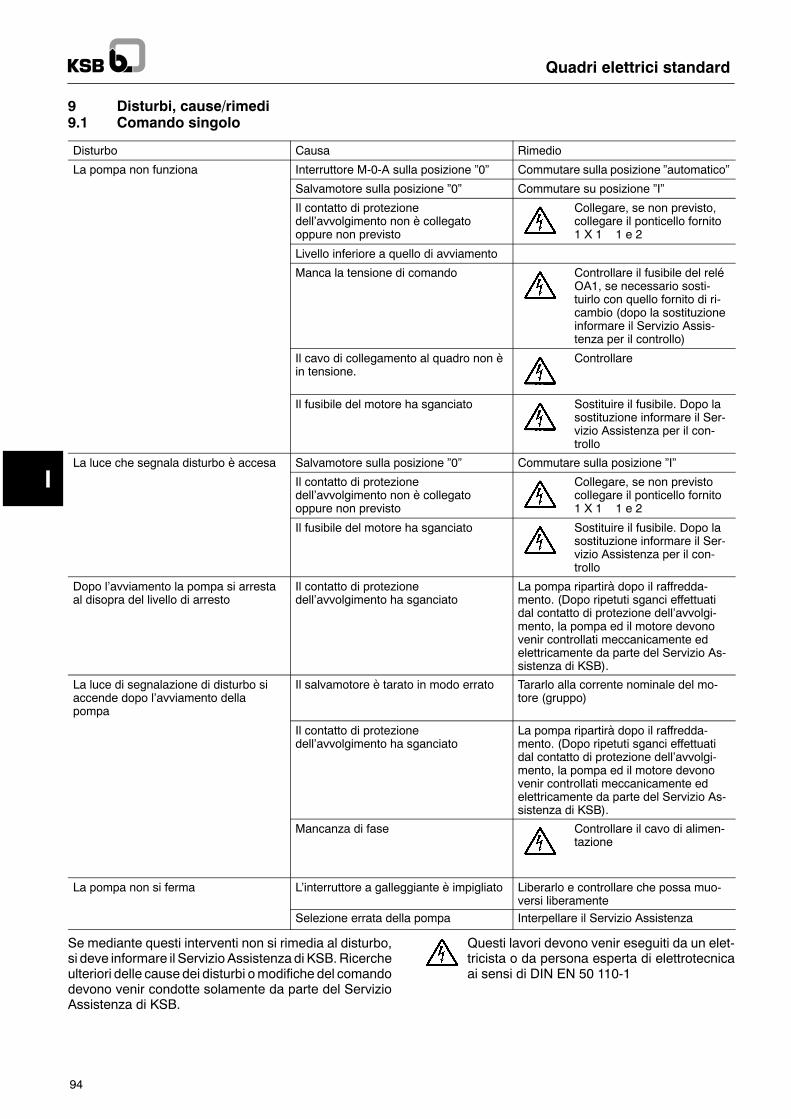
I
Quadri elettrici standard
94
9 Disturbi, cause/rimedi9.1 Comando singolo
Disturbo Causa Rimedio
La pompa non funziona Interruttore M-0-A sulla posizione �0� Commutare sulla posizione �automatico�
Salvamotore sulla posizione �0� Commutare su posizione �I�
Il contatto di protezionedell�avvolgimento non è collegatooppure non previsto
Collegare, se non previsto,collegare il ponticello fornito1 X 1 1 e 2
Livello inferiore a quello di avviamento
Manca la tensione di comando Controllare il fusibile del reléOA1, se necessario sosti-tuirlo con quello fornito di ri-cambio (dopo la sostituzioneinformare il Servizio Assis-tenza per il controllo)
Il cavo di collegamento al quadro non èin tensione.
Controllare
Il fusibile del motore ha sganciato Sostituire il fusibile. Dopo lasostituzione informare il Ser-vizio Assistenza per il con-trollo
La luce che segnala disturbo è accesa Salvamotore sulla posizione �0� Commutare sulla posizione �I�
Il contatto di protezionedell�avvolgimento non è collegatooppure non previsto
Collegare, se non previstocollegare il ponticello fornito1 X 1 1 e 2
Il fusibile del motore ha sganciato Sostituire il fusibile. Dopo lasostituzione informare il Ser-vizio Assistenza per il con-trollo
Dopo l�avviamento la pompa si arrestaal disopra del livello di arresto
Il contatto di protezionedell�avvolgimento ha sganciato
La pompa ripartirà dopo il raffredda-mento. (Dopo ripetuti sganci effettuatidal contatto di protezione dell�avvolgi-mento, la pompa ed il motore devonovenir controllati meccanicamente edelettricamente da parte del Servizio As-sistenza di KSB).
La luce di segnalazione di disturbo siaccende dopo l�avviamento dellapompa
Il salvamotore è tarato in modo errato Tararlo alla corrente nominale del mo-tore (gruppo)
Il contatto di protezionedell�avvolgimento ha sganciato
La pompa ripartirà dopo il raffredda-mento. (Dopo ripetuti sganci effettuatidal contatto di protezione dell�avvolgi-mento, la pompa ed il motore devonovenir controllati meccanicamente edelettricamente da parte del Servizio As-sistenza di KSB).
Mancanza di fase Controllare il cavo di alimen-tazione
La pompa non si ferma L�interruttore a galleggiante è impigliato Liberarlo e controllare che possa muo-versi liberamente
Selezione errata della pompa Interpellare il Servizio Assistenza
Se mediante questi interventi non si rimedia al disturbo,si deve informare il Servizio Assistenza di KSB.Ricercheulteriori delle cause dei disturbi omodifiche del comandodevono venir condotte solamente da parte del ServizioAssistenza di KSB.
Questi lavori devono venir eseguiti da un elet-tricista o da persona esperta di elettrotecnicaai sensi di DIN EN 50 110-1

I
Quadri elettrici standard
95
9.2 Comando doppio
Disturbo Causa Rimedio
La pompa non funziona Interruttore M-0-A sulla posizione �0� Commutare sulla posizione �automatico�
Salvamotore sulla posizione �0� Commutare su posizione �I�
Il contatto di protezionedell�avvolgimento non è collegatooppure non previsto
Collegare, se non previstocollegare i ponticelli fornitiPompa 1 => 1 X 1 1 e 2Pompa 2 => 1 X 1 3 e 4
Livello inferiore a quello di avviamento
Manca la tensione di comando Controllare il fusibile del reléOA1, se necessario sosti-tuirlo con quello fornito di ri-cambio (dopo la sostituzioneinformare il Servizio Assis-tenza per il controllo)
Il cavo di collegamento al quadro non èin tensione.
Controllare
Interruttore esterno/interno sul relè dicomando OA1 in posizione �esterno� enessun segnale esterno dal contatto dicommutazione
Controllare , eventualmentecommutare su �interno�all�apparecchio di comandoOA1.
La luce che segnala disturbo è accesa Salvamotore sulla posizione �0� Commutare sulla posizione �I�
I contatti di protezione dell�avvolgimentonon sono collegati oppure non previsti
Collegare, se non previsti,collegare i ponticelli fornitiPompa 1 => 1 X 1 1 e 2Pompa 2 => 1 X 1 3 e 4
La luce di segnalazione di disturbo siaccende dopo l�avviamento dellapompa
Il salvamotore è tarato in modo errato Tararlo alla corrente nominale del mo-tore (gruppo)
Il contatto di protezionedell�avvolgimento ha sganciato
La pompa ripartirà dopo il raffredda-mento. (Dopo ripetuti sganci effettuatidal contatto di protezione dell�avvolgi-mento, la pompa ed il motore devonovenir controllati meccanicamente edelettricamente da parte del Servizio As-sistenza di KSB).
Mancanza di fase Controllare il cavo di alimen-tazione
Nessun cambio di pompa Un salvamotore non è sulla posizione�I�
Commutare
Un interruttore M-0-A sulla posizione�0�
Commutare su �automatico�
Contatti di protezione dell�avvolgimentonon collegati oppure nessun ponticelloinserito
Collegare
La pompa non si ferma L�interruttore a galleggiante è impigliato Liberarlo e controllare che possa muo-versi liberamente
Selezione errata della pompa Interpellare il Servizio Assistenza
Dopo ogni intervento funzionano en-trambe le pompe
L�interruttore a galleggiante 1 èimpigliato o guasto
Liberarlo e controllare che possa muo-versi liberamente.
Se mediante questi interventi non si rimedia al disturbo,si deve informare il Servizio Assistenza di KSB.Ricercheulteriori delle cause dei disturbi omodifiche del comandodevono venir condotte solamente da parte del ServizioAssistenza di KSB.
Questi lavori devono venir eseguiti da un elet-tricista o da persona esperta di elettrotecnicaai sensi di DIN EN 50 110-1

Technische
Änderungenbleibenvorbehalten.
2315.8-90
1.1.1999
01052835
KSB Aktiengesellschaft67225 Frankenthal " Johann-Klein-Str. 9 " 67227 Frankenthal (Deutschland)Tel. +49 6233 86-0 " Fax +49 6233 86-3401 " www.ksb.de
Standard-Schaltgeräte