Embed Size (px)
Citation preview
11
建立基本的StateFlow模型
元智大學機械系陳傳生博士
Copyright 1984 - 1999 by The MathWorks, Inc.
2建立基本的Stateflow模型
課程目標w 了解Simulink/Stateflow環境內的術語.
w 使用Graphic Edition建立stateflow diagram.w 建立包含Stateflow block的基本 Simulink 模型.w 建立Stateflow/Simulink之間的資料交換介面.
w 模擬Stateflow/Simulink的執行.

22
Copyright 1984 - 1999 by The MathWorks, Inc.
3建立基本的Stateflow模型
How Does Stateflow Work?建立及模擬一個Simulink/Stateflow的模型將用到下列工具
Data Dictionary
GraphicsEditor
DialogBoxes
Explorer
FinderGeneratedCode
Simulink
Debugger
Copyright 1984 - 1999 by The MathWorks, Inc.
4建立基本的Stateflow模型
術語TerminologyStateflow Machine
The collection of all Stateflow diagrams contained within a single Simulink model.
Stateflow BlockA block inside a Simulink diagram that represents Stateflow.
Stateflow Diagram or ChartThe Stateflow contents that are contained in a single graphical window and correspond to one Stateflow Block.
one-to-one
33
Copyright 1984 - 1999 by The MathWorks, Inc.
5建立基本的Stateflow模型
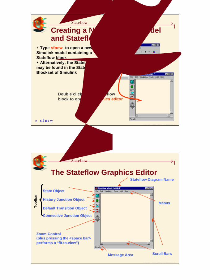
Creating a New Simulink Model and Stateflow Diagram
w Type sfnew to open a new Simulink model containing a Stateflow blockw Alternatively, the Stateflow blockmay be found in the Stateflow Blockset of Simulink
Double click on the Stateflowblock to open the graphics editor
» sfnew
Copyright 1984 - 1999 by The MathWorks, Inc.
6建立基本的Stateflow模型
The Stateflow Graphics Editor
State Object
History Junction Object
Default Transition Object
Connective Junction Object
To
olb
ar
Message Area
Zoom Control(plus pressing the <space bar>performs a “fit-to-view”)
Menus
Scroll Bars
Stateflow Diagram Name
44
Copyright 1984 - 1999 by The MathWorks, Inc.
7建立基本的Stateflow模型
Graphics Editor Menus
Add: Create a new data or event object
Simulation: Open the Simulation Parameter dialog box, start a simulation
Edit: Copy, paste, and change the format(font, color, size, etc… ) of selected objects.
File: Save or print current model; open a newmodel
Help: Open the online help (HTML)
Tools: Open other Stateflow tools: Explorer,Finder, Debugger, Simulation Target
Copyright 1984 - 1999 by The MathWorks, Inc.
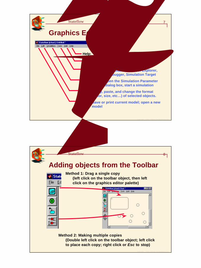
8建立基本的Stateflow模型
Adding objects from the ToolbarMethod 1: Drag a single copy
(left click on the toolbar object, then leftclick on the graphics editor palette)
Method 2: Making multiple copies(Double left click on the toolbar object; left click to place each copy; right click or Esc to stop)
55
Copyright 1984 - 1999 by The MathWorks, Inc.
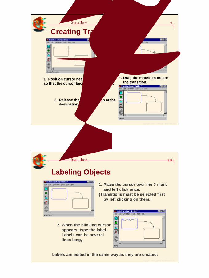
9建立基本的Stateflow模型
Creating Transitions
1. Position cursor near source objectso that the cursor becomes a crosshair.
2. Drag the mouse to create the transition.
3. Release the mouse button at the destination object.
Copyright 1984 - 1999 by The MathWorks, Inc.
10建立基本的Stateflow模型
Labeling Objects
1. Place the cursor over the ? mark and left click once.
(Transitions must be selected first by left clicking on them.)
2. When the blinking cursor appears, type the label. Labels can be several lines long, 不能有空格
Labels are edited in the same way as they are created.
66
Copyright 1984 - 1999 by The MathWorks, Inc.
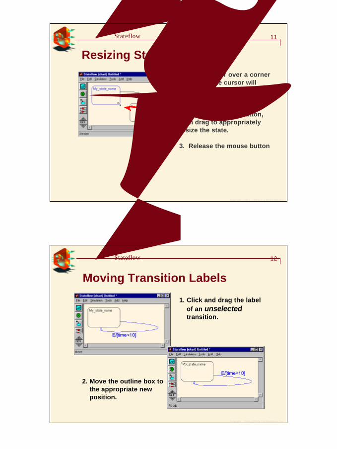
11建立基本的Stateflow模型
Resizing States1. Place cursor over a cornerof a state; the cursor will become a bi-directional arrow.
2. Press left mouse button, then drag to appropriately resize the state.
3. Release the mouse button
Copyright 1984 - 1999 by The MathWorks, Inc.
12建立基本的Stateflow模型
Moving Transition Labels
1. Click and drag the label of an unselectedtransition.
2. Move the outline box to the appropriate new position.
77
Copyright 1984 - 1999 by The MathWorks, Inc.
13建立基本的Stateflow模型
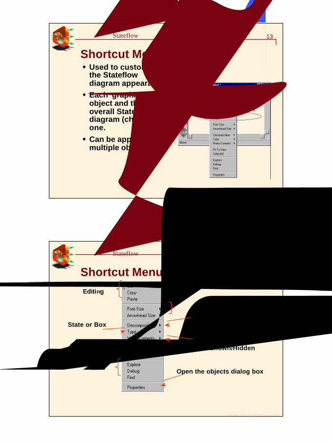
Shortcut Menuw Used to customize
the Stateflow diagram appearance.w Each graphical
object and the overall Stateflow diagram (chart) has one.w Can be applied to
multiple objects.
滑鼠右鍵或是Ctrl+ 滑鼠左鍵
Copyright 1984 - 1999 by The MathWorks, Inc.
14建立基本的Stateflow模型
Shortcut Menu
Open the objects dialog box
Editing
啟動其他工具
調整大小
Parallel or Exclusive
Grouped/Ungroupedand Shown/Hidden
State or Box
88
Copyright 1984 - 1999 by The MathWorks, Inc.
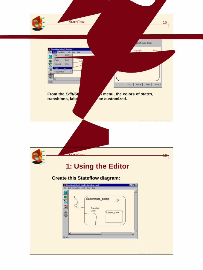
15建立基本的Stateflow模型
改變顏色
From the Edit/Style pulldown menu, the colors of states, transitions, labels, etc can be customized.
Copyright 1984 - 1999 by The MathWorks, Inc.
16建立基本的Stateflow模型
練習 1: Using the Editor
Create this Stateflow diagram:
99
Copyright 1984 - 1999 by The MathWorks, Inc.
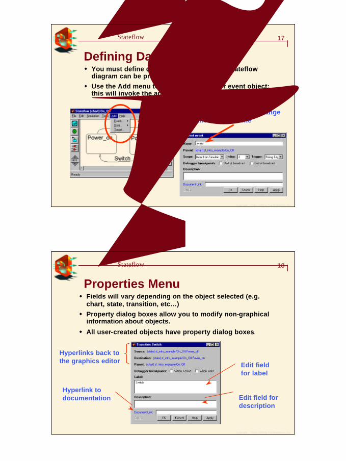
17建立基本的Stateflow模型
Defining Data and Eventsw You must define data and events before a Stateflow
diagram can be properly parsed.
w Use the Add menu to define a new data or event object; this will invoke the appropriate dialog.
You will generally change the default name
Copyright 1984 - 1999 by The MathWorks, Inc.
18建立基本的Stateflow模型
Properties Menuw Fields will vary depending on the object selected (e.g.
chart, state, transition, etc… )
w Property dialog boxes allow you to modify non-graphical information about objects.
w All user-created objects have property dialog boxes.
Hyperlinks back to the graphics editor
Edit field for label
Edit field for description
Hyperlink to documentation
1010
Copyright 1984 - 1999 by The MathWorks, Inc.
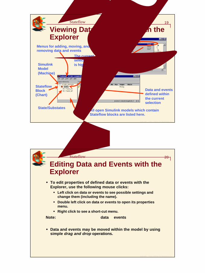
19建立基本的Stateflow模型
Viewing Data and Events with the Explorer
Simulink Model (Machine)
Stateflow Block (Chart)
Menus for adding, moving, andremoving data and events
Data and events defined within the current selection
All open Simulink models which contain Stateflow blocks are listed here.
The current selectionis highlighted
State/Substates
Copyright 1984 - 1999 by The MathWorks, Inc.
20建立基本的Stateflow模型
Editing Data and Events with the Explorerw To edit properties of defined data or events with the
Explorer, use the following mouse clicks:w Left click on data or events to see possible settings and
change them (including the name).w Double left click on data or events to open its properties
menu.w Right click to see a short-cut menu.
Note:可以同時選取及修改多個data 或events
w Data and events may be moved within the model by using simple drag and drop operations.
1111
Copyright 1984 - 1999 by The MathWorks, Inc.
21建立基本的Stateflow模型
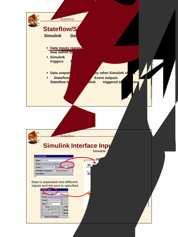
Stateflow/Simulink InterfacingSimulink透過Data 及 Events 與Stateflow溝通
輸入w Data inputs represent numerical values, the usual signal
flow within Simulink.w Simulink中的trigger 對應到 Stateflow 內的Event. 模擬時的
triggers送入Stateflow chart時, 等於發生一個事件(Event).
輸出w Data outputs are used as any other Simulink signal.w 從Stateflow diagram送出的Event outputs可用來觸發其他
Stateflow blocks或Simulink中的triggered subsystems.
Copyright 1984 - 1999 by The MathWorks, Inc.
22建立基本的Stateflow模型
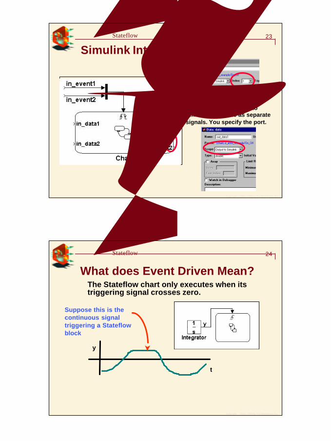
Simulink Interface Inputs 從Simulink來的信號不只一個時,必須先聚合成一個向量,然後透過index,得到特定的event信號
Data is separated into differentinputs and the port is specified
1212
Copyright 1984 - 1999 by The MathWorks, Inc.
23建立基本的Stateflow模型
Simulink Interface Outputs
Data and event outputs to Simulink originate as separate signals. You specify the port.
Copyright 1984 - 1999 by The MathWorks, Inc.
24建立基本的Stateflow模型
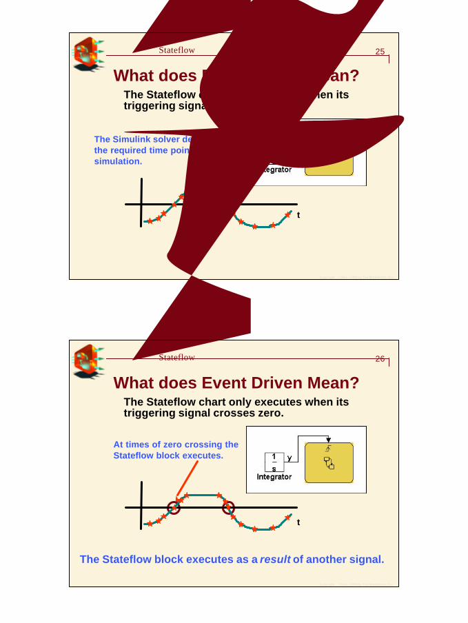
What does Event Driven Mean?The Stateflow chart only executes when its triggering signal crosses zero.
y
t
Suppose this is the continuous signal triggering a Stateflow block
1313
Copyright 1984 - 1999 by The MathWorks, Inc.
25建立基本的Stateflow模型
What does Event Driven Mean?The Stateflow chart only executes when its triggering signal crosses zero.
The Simulink solver determines the required time points for simulation.
t
Copyright 1984 - 1999 by The MathWorks, Inc.
26建立基本的Stateflow模型
What does Event Driven Mean?The Stateflow chart only executes when its triggering signal crosses zero.
At times of zero crossing the Stateflow block executes.
The Stateflow block executes as a result of another signal.
t
1414
Copyright 1984 - 1999 by The MathWorks, Inc.
27建立基本的Stateflow模型
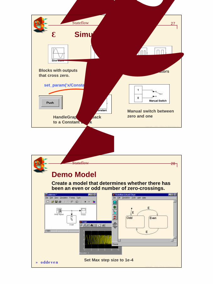
如何在Simulink產生Events
Blocks with outputs that cross zero.
HandleGraphic Callback to a Constant Block
Manual switch between zero and one
Step Functions Pulse Generators
set_param('x/Constant','value','0')
Copyright 1984 - 1999 by The MathWorks, Inc.
28建立基本的Stateflow模型
Demo ModelCreate a model that determines whether there has been an even or odd number of zero-crossings.
Set Max step size to 1e-4» oddeven
1515
Copyright 1984 - 1999 by The MathWorks, Inc.
29建立基本的Stateflow模型
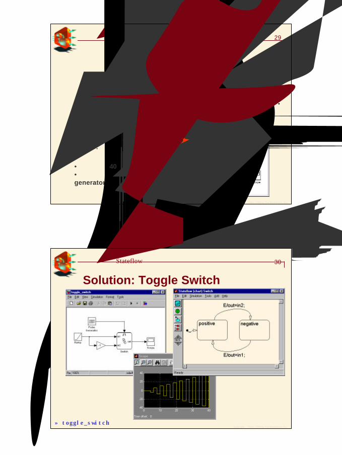
練習 2: Toggle Switch 建立一項模擬toggle switch的StateFlow 模型:
w 使用兩個states及兩個transitions在兩個states間轉換.
w 當輸入的切換信號改變時,它的狀態改變成另一個狀態.w 包含兩個data inputs及一個data output. 輸出值在兩個輸入值切換.
建立如右圖的模型,並且完成模擬:
•模擬時間 40 秒•使用一個週期4秒的 pulse generator
Copyright 1984 - 1999 by The MathWorks, Inc.
30建立基本的Stateflow模型
Solution: Toggle Switch
» toggle_switch
1616
Copyright 1984 - 1999 by The MathWorks, Inc.
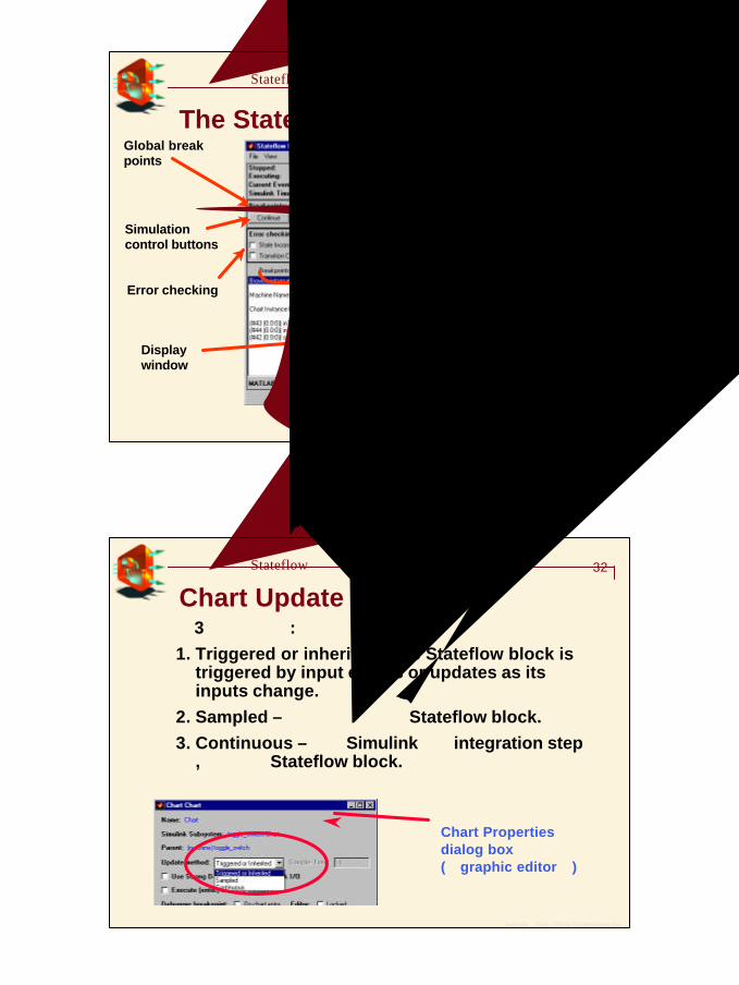
31建立基本的Stateflow模型
The Stateflow DebuggerCurrent executionstatus
Display window
Animation controls
Global break points
Simulationcontrol buttons
Displayoptions
Error checking
Command lineevaluations
Copyright 1984 - 1999 by The MathWorks, Inc.
32建立基本的Stateflow模型
Chart Update Methods有3種更新方式:1. Triggered or inherited –The Stateflow block is
triggered by input events or updates as its inputs change.
2. Sampled – 以固定速率更動Stateflow block.3. Continuous – 每次Simulink執行integration step時
,同時評估Stateflow block.
Chart Propertiesdialog box(在graphic editor內)
1717
Copyright 1984 - 1999 by The MathWorks, Inc.
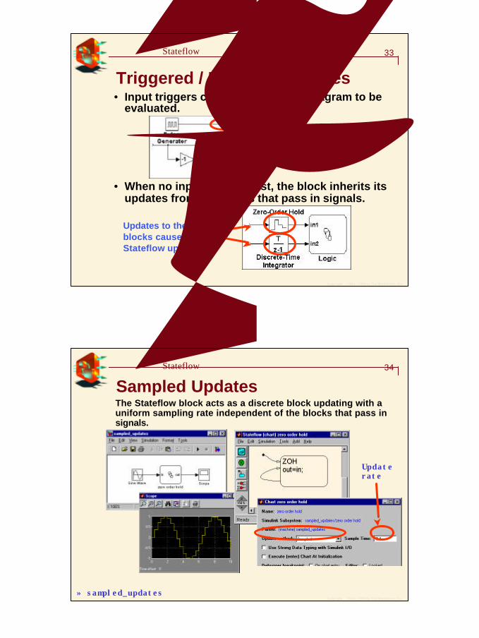
33建立基本的Stateflow模型
Triggered / Inherited Updates• Input triggers cause the Stateflow diagram to be
evaluated.
Zero crossing detection on the input signal causes updates
Updates to theseblocks cause aStateflow update
• When no input events exist, the block inherits its updates from the blocks that pass in signals.
Copyright 1984 - 1999 by The MathWorks, Inc.
34建立基本的Stateflow模型
Sampled UpdatesThe Stateflow block acts as a discrete block updating with a uniform sampling rate independent of the blocks that pass in signals.
» sampled_updates
Updaterate
1818
Copyright 1984 - 1999 by The MathWorks, Inc.
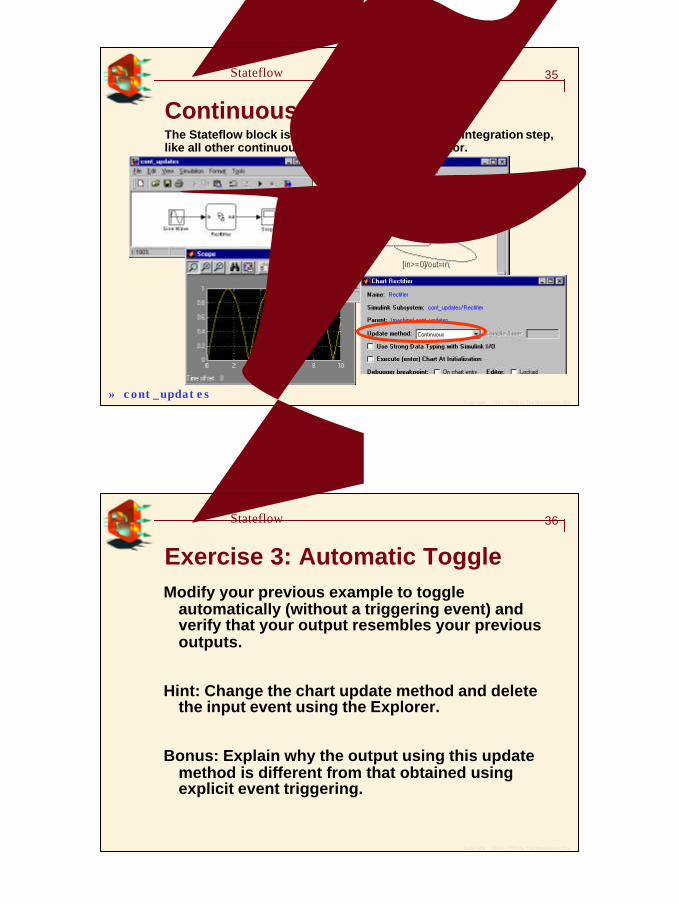
35建立基本的Stateflow模型
Continuous UpdatesThe Stateflow block is evaluated at each Simulation integration step, like all other continuous blocks, e.g., gain, integrator.
» cont_updates
Copyright 1984 - 1999 by The MathWorks, Inc.
36建立基本的Stateflow模型
Exercise 3: Automatic ToggleModify your previous example to toggle
automatically (without a triggering event) and verify that your output resembles your previous outputs.
Hint: Change the chart update method and delete the input event using the Explorer.
Bonus: Explain why the output using this update method is different from that obtained using explicit event triggering.
1919
Copyright 1984 - 1999 by The MathWorks, Inc.
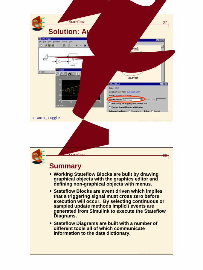
37建立基本的Stateflow模型
Solution: Automatic Toggle
» auto_toggle
Copyright 1984 - 1999 by The MathWorks, Inc.
38建立基本的Stateflow模型
Summaryw Working Stateflow Blocks are built by drawing
graphical objects with the graphics editor and defining non-graphical objects with menus.w Stateflow Blocks are event driven which implies
that a triggering signal must cross zero before execution will occur. By selecting continuous or sampled update methods implicit events are generated from Simulink to execute the Stateflow Diagrams.
w Stateflow Diagrams are built with a number of different tools all of which communicate information to the data dictionary.