Embed Size (px)
Citation preview
Stereo Calibration & Rectification
3/13/12 ECEn 631 2
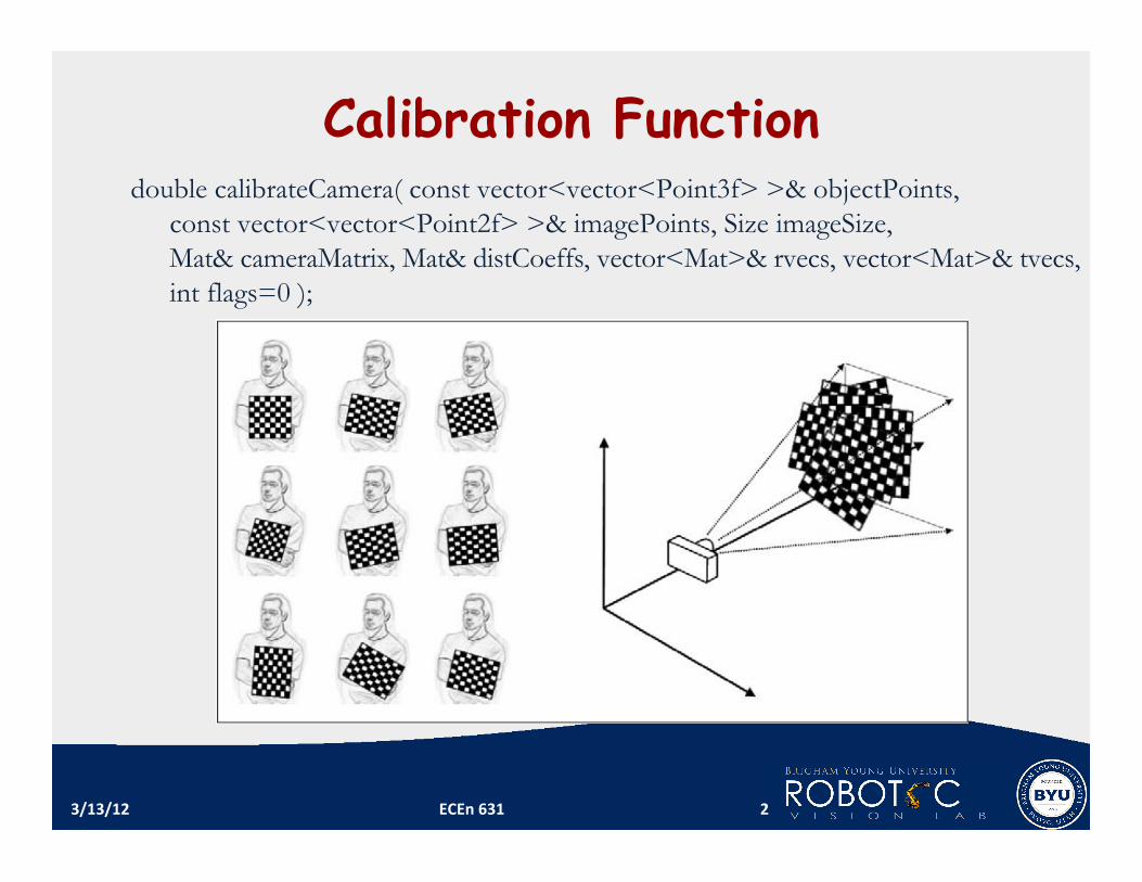
Calibration Function double calibrateCamera( const vector<vector<Point3f> >& objectPoints,
const vector<vector<Point2f> >& imagePoints, Size imageSize, Mat& cameraMatrix, Mat& distCoeffs, vector<Mat>& rvecs, vector<Mat>& tvecs, int flags=0 );
Stereo Calibration Using homography calibra1on method, we can get mul1ple sets of extrinsic parameters, one for each chessboard view (between the camera and chessboard).
Unique camera intrinsic and distor1on parameters are calculated through homography calibra1on method
If a 3D known object is available, then solvePnP() can be used to get a set of R and T (between the camera and the calibra1on object) for each camera.
Alterna1vely, we can obtain one set of R and T (between the camera and the calibra1on object) for each camera by using the direct or indirect camera calibra1on method.
3/13/12 ECEn 631 3
Stereo Calibration
Assuming that we used direct or indirect method or solvePnP() to obtain a set of unique extrinsic parameters for each camera, then
Pw is the 3D point seen by both cameras. Pl is the same 3D point seen by the leG camera Pr is the same 3D point seen by the right camera Rl and Tl and Rr and Tr define the 3D rela1onship between the calibra1on object and the leG and right cameras, respec1vely.
3/13/12 ECEn 631 4
!
Pl= R
lP
w+ T
l and P
r= R
rP
w+ T
r
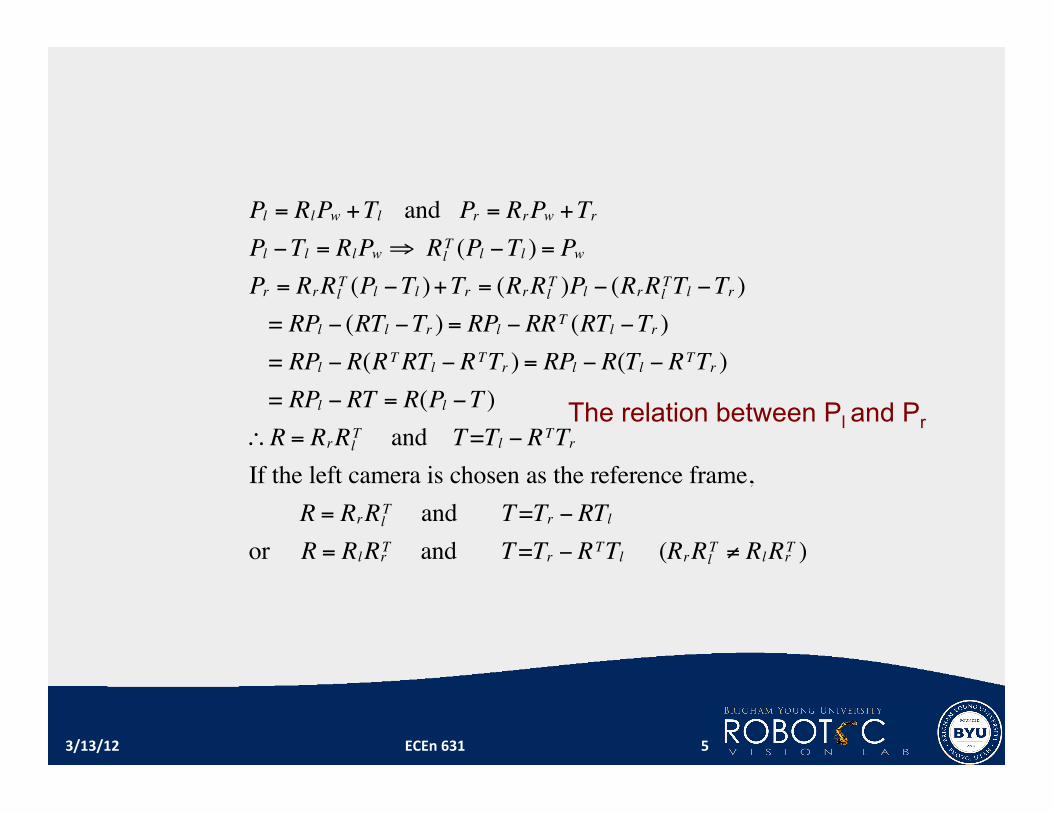
Pl = RlPw +Tl and Pr = RrPw +Tr
Pl !Tl = RlPw " Rl
T (Pl !Tl ) = Pw
Pr = RrRl
T (Pl !Tl )+Tr = (RrRl
T )Pl ! (RrRl
TTl !Tr )
= RPl ! (RTl !Tr ) = RPl ! RRT (RTl !Tr )
= RPl ! R(RTRTl ! RTTr ) = RPl ! R(Tl ! RTTr )
= RPl ! RT = R(Pl !T )
#R = RrRl
T and T=Tl ! RTTr
If the left camera is chosen as the reference frame,
R = RrRl
T and T=Tr ! RTl
or R = RlRrT and T=Tr ! RTTl (RrRl
T $ RlRrT )
The relation between Pl and Pr
3/13/12 ECEn 631 5

OpenCV Functions Single camera calibra1on double calibrateCamera( const vector<vector<Point3f> >& objectPoints,
const vector<vector<Point2f> >& imagePoints, Size imageSize, Mat& cameraMatrix, Mat& distCoeffs, vector<Mat>& rvecs, vector<Mat>& tvecs, int flags=0 );
Stereo calibra1on double stereoCalibrate( const vector<vector<Point3f> >& objectPoints,
const vector<vector<Point2f> >& imagePoints1, const vector<vector<Point2f> >& imagePoints2, Mat& cameraMatrix1, Mat& distCoeffs1, Mat& cameraMatrix2, Mat& distCoeffs2, Size imageSize, Mat& R, Mat& T, Mat& E, Mat& F, TermCriteria term crit = TermCriteria(TermCriteria::COUNT+ TermCriteria::EPS, 30, 1e-6), int flags=CALIB FIX INTRINSIC );
3/13/12 ECEn 631 6
OpenCV Functions calibrateCamera() outputs one set of intrinsic and distor1on parameters and mul1ple sets of extrinsic parameters (between the camera and the chessboard views).
stereoCalibrate() internally performs calibrateCamera() for leG and right cameras separately and use those mul1ple sets of extrinsic parameters to calculate a single rota1on matrix and transla1on vector (between the two cameras).
3/13/12 ECEn 631 7
stereoCalibrate() Because of image noise and rounding error, each chessboard pair results in slightly different values for rota-on and transla-on.
stereoCalibrate() uses an itera1ve algorithm to find the minimum of the reprojec1on error of the chessboard corners for both camera views.
The resul1ng rota1on matrix and transla1on vector does not make images row‐aligned as they would have been seen using canonical configura1on.
3/13/12 ECEn 631 8
stereoCalibrate() Chessboard size is cri1cal It affects Tx and 3D Z measurement If the chessboard size used is half of the actual size, then – the system will think the chessboard is at half of the actual distance (it appears on the image twice as big for the wrong half size).
– Since the distance is thought to be half, the baseline is reported half of the actual length (half of the actual Tx)
3/13/12 ECEn 631 9
StereoCalibrate() objectPoints is the vector of vectors of points on the calibration
pattern in its coordinate system, one vector per view. If the same calibration pattern is shown in each view and it’s fully visible then all the vectors will be the same, although it is possible to use partially occluded patterns, or even different patterns in different views - then the vectors will be different.
objectPoints are 3D points, but since they are in the pattern coordinate system, then if the rig is planar, it may make sense to put the model to the XY coordinate plane, so that Z-coordinate of each input object point is 0.
imagePoints1 and imagePoints2 are the vector of vectors of corresponding image (corner) points.
3/13/12 ECEn 631 10
StereoCalibrate()
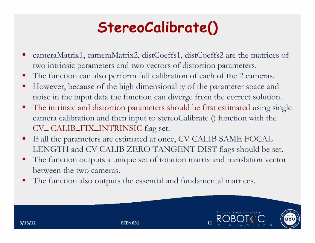
cameraMatrix1, cameraMatrix2, distCoeffs1, distCoeffs2 are the matrices of two intrinsic parameters and two vectors of distortion parameters.
The function can also perform full calibration of each of the 2 cameras. However, because of the high dimensionality of the parameter space and
noise in the input data the function can diverge from the correct solution. The intrinsic and distortion parameters should be first estimated using single
camera calibration and then input to stereoCalibrate () function with the CV_ CALIB_FIX_INTRINSIC flag set.
If all the parameters are estimated at once, CV CALIB SAME FOCAL LENGTH and CV CALIB ZERO TANGENT DIST flags should be set.
The function outputs a unique set of rotation matrix and translation vector between the two cameras.
The function also outputs the essential and fundamental matrices.
3/13/12 ECEn 631 11
ol
or
T
Z (cx, cy)
(cx, cy)
xl
xr
yl
yr
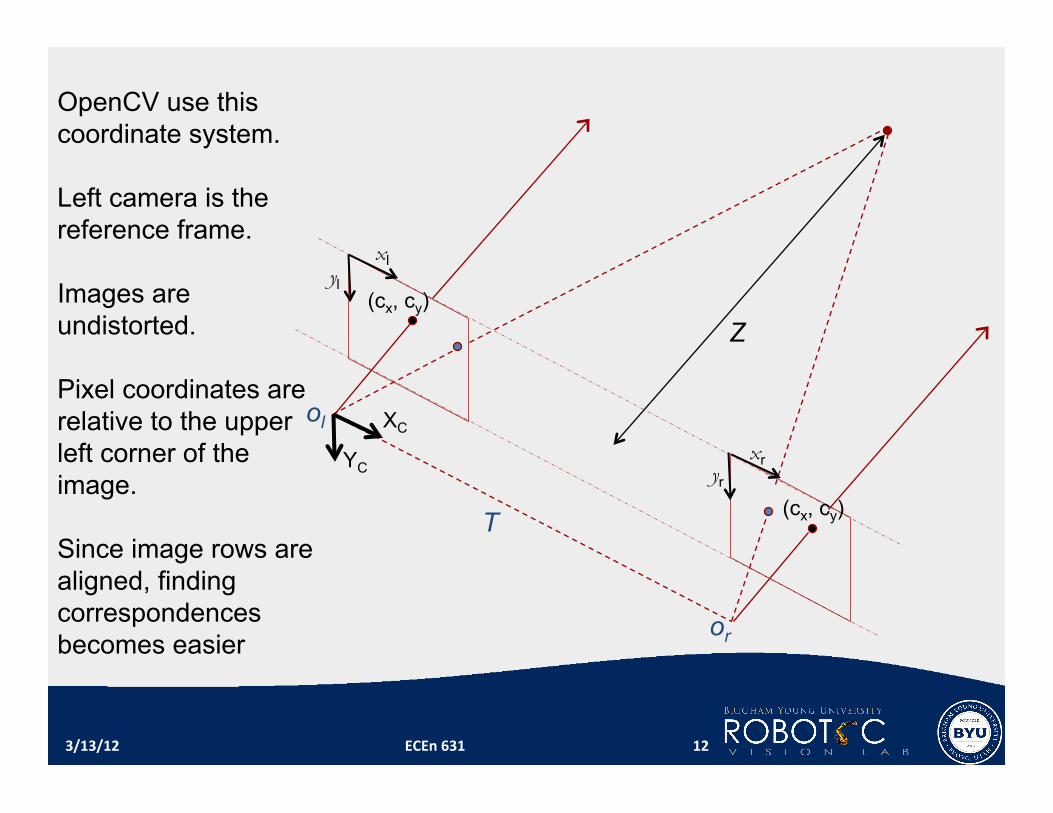
OpenCV use this coordinate system. Left camera is the reference frame. Images are undistorted. Pixel coordinates are relative to the upper left corner of the image. Since image rows are aligned, finding correspondences becomes easier
XC
YC
3/13/12 ECEn 631 12
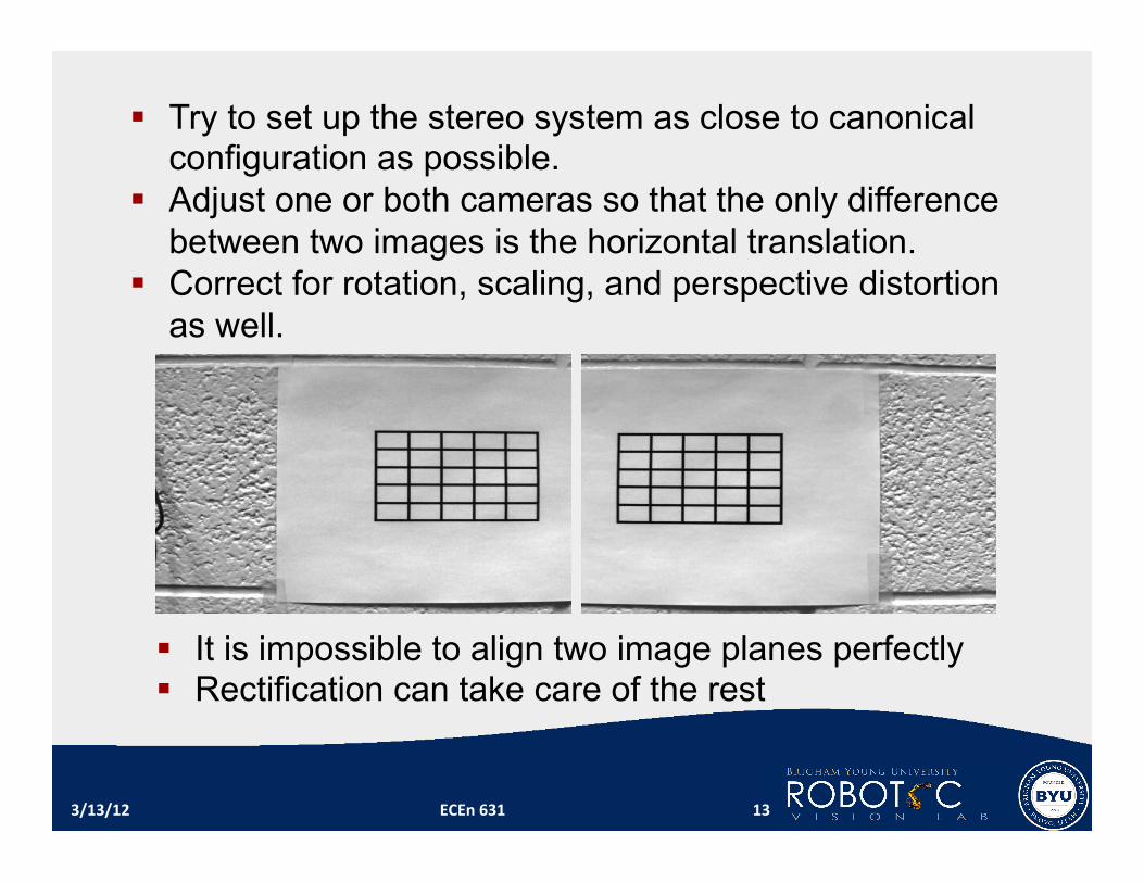
Try to set up the stereo system as close to canonical configuration as possible.
Adjust one or both cameras so that the only difference between two images is the horizontal translation.
Correct for rotation, scaling, and perspective distortion as well.
3/13/12 ECEn 631 13
It is impossible to align two image planes perfectly Rectification can take care of the rest

Why? – To change a 2‐D search problem in general (for finding corresponding points) into a 1‐D search problem (more reliable and can save 1me)
How? – The rec1fied images can be thought of as acquired by a new stereo rig, obtained by rota1ng the original cameras around their op1cal centers.
– Reproject both image planes so that they resides in the exact same plane and image rows perfectly aligned into a frontal parallel (canonical) configura1on.
3/13/12 ECEn 631 14
Image Rectification
ol
or
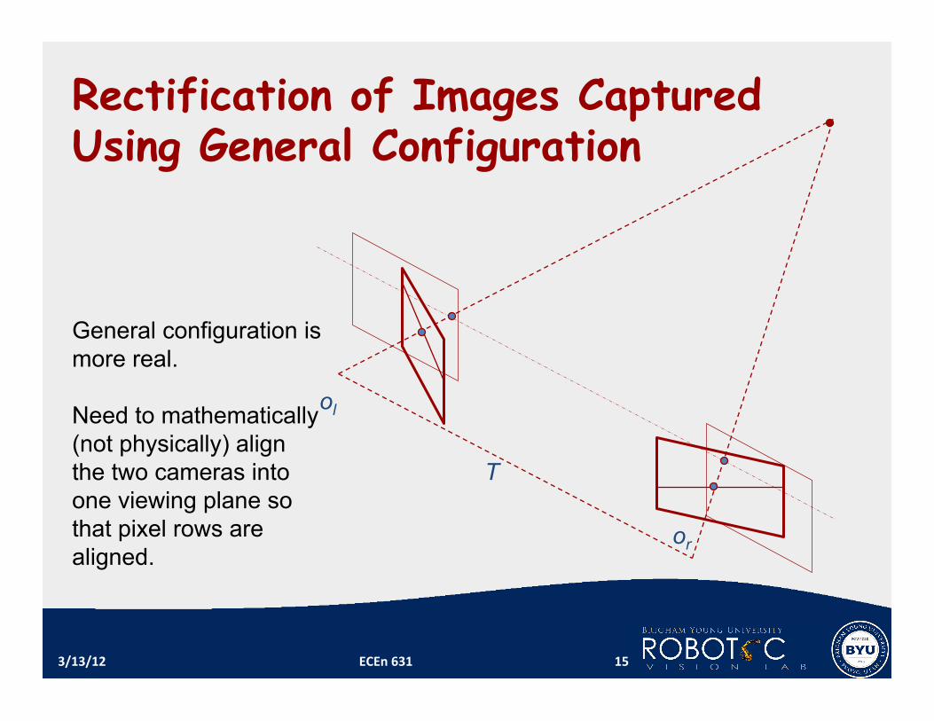
Rectification of Images Captured Using General Configuration
T
General configuration is more real. Need to mathematically (not physically) align the two cameras into one viewing plane so that pixel rows are aligned.
3/13/12 ECEn 631 15
]',','['
'
]',','[],,[
zyxzfp
zyxpRfyxp
l
ll
Tl
=
=
=
!
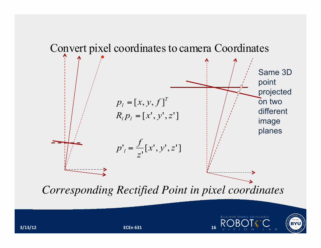
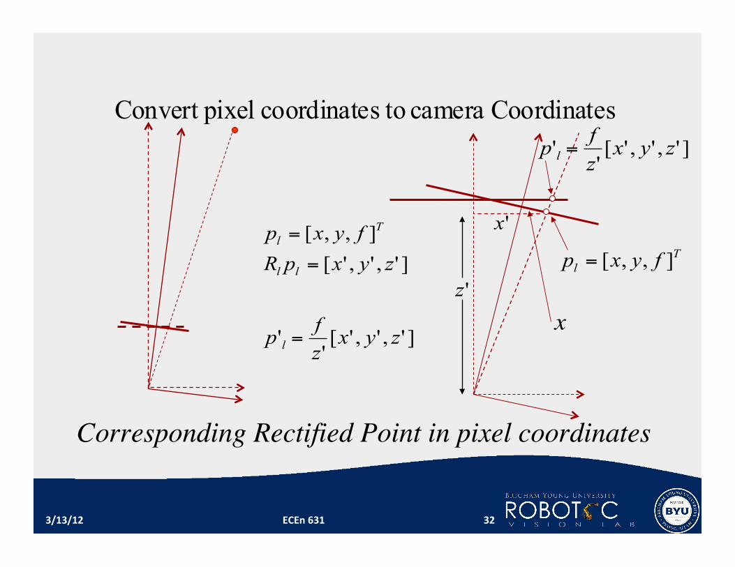
Corresponding Rectified Point in pixel coordinates
sCoordinatecamera toscoordinate pixelConvert
3/13/12 ECEn 631 16
Same 3D point projected on two different image planes
Image Rectification The geometry transforma1on that changes a general camera configura1on with non‐parallel epipolar lines to the canonical one.
Epipolar lines become collinear and parallel to the image horizontal axis. Where are the epipoles?
It is oGen used when stereo correspondence is to be determined by finding line‐wise matching points.
For high precision reconstruc1on, image rec1fica1on induces re‐sampling and interpola1on that cause loss of resolu1on.
The rec1fied images can be thought of as acquired by rotated cameras.
3/13/12 ECEn 631 17
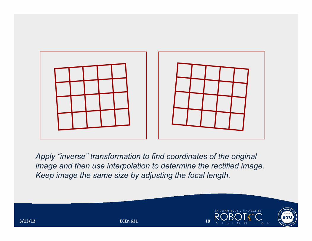
Apply “inverse” transformation to find coordinates of the original image and then use interpolation to determine the rectified image. Keep image the same size by adjusting the focal length.
3/13/12 ECEn 631 18
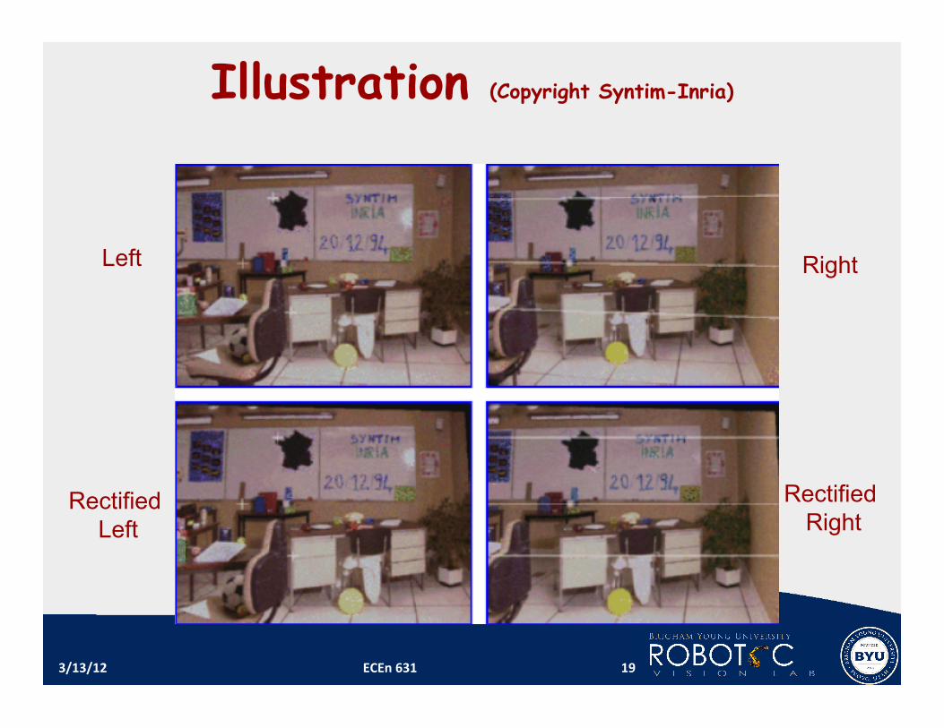
Illustration (Copyright Syntim-Inria)
3/13/12 ECEn 631 19
Left
Rectified Left
Right
Rectified Right
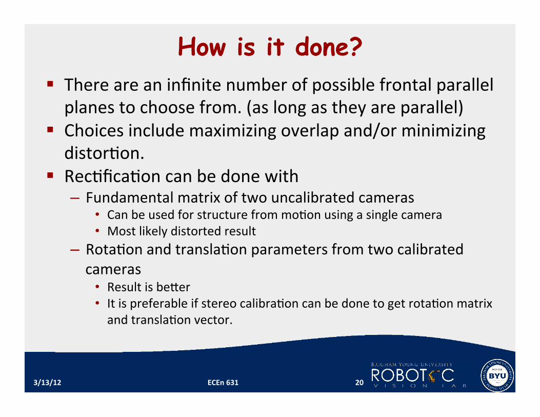
How is it done? There are an infinite number of possible frontal parallel planes to choose from. (as long as they are parallel)
Choices include maximizing overlap and/or minimizing distor1on.
Rec1fica1on can be done with – Fundamental matrix of two uncalibrated cameras
• Can be used for structure from mo1on using a single camera • Most likely distorted result
– Rota1on and transla1on parameters from two calibrated cameras
• Result is beYer • It is preferable if stereo calibra1on can be done to get rota1on matrix and transla1on vector.
3/13/12 ECEn 631 20
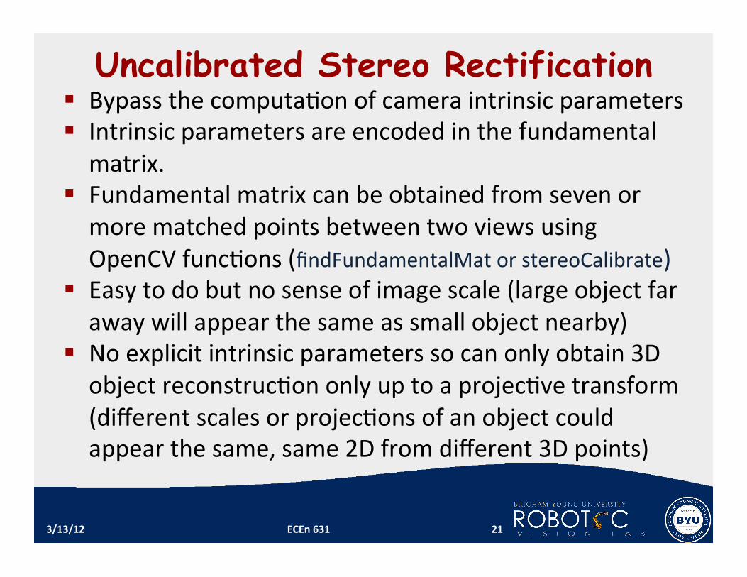
Uncalibrated Stereo Rectification Bypass the computa1on of camera intrinsic parameters Intrinsic parameters are encoded in the fundamental matrix.
Fundamental matrix can be obtained from seven or more matched points between two views using OpenCV func1ons (findFundamentalMat or stereoCalibrate)
Easy to do but no sense of image scale (large object far away will appear the same as small object nearby)
No explicit intrinsic parameters so can only obtain 3D object reconstruc1on only up to a projec1ve transform (different scales or projec1ons of an object could appear the same, same 2D from different 3D points)
3/13/12 ECEn 631 21
3/13/12 ECEn 631 22
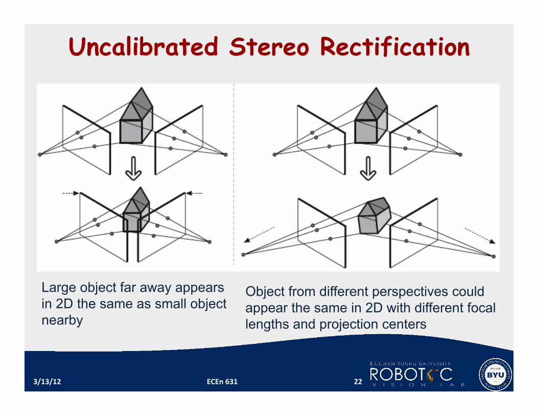
Uncalibrated Stereo Rectification
Large object far away appears in 2D the same as small object nearby
Object from different perspectives could appear the same in 2D with different focal lengths and projection centers
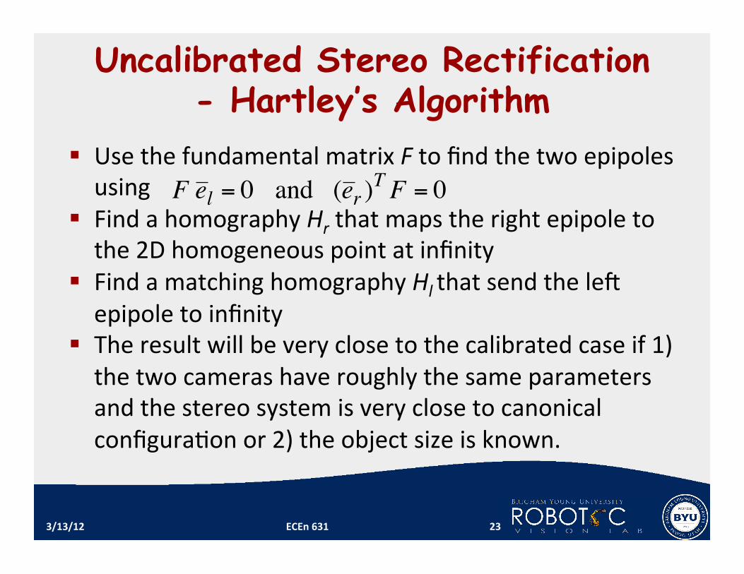
Uncalibrated Stereo Rectification - Hartley’s Algorithm
Use the fundamental matrix F to find the two epipoles using
Find a homography Hr that maps the right epipole to the 2D homogeneous point at infinity
Find a matching homography Hl that send the leG epipole to infinity
The result will be very close to the calibrated case if 1) the two cameras have roughly the same parameters and the stereo system is very close to canonical configura1on or 2) the object size is known.
3/13/12 ECEn 631 23
!
F e l = 0 and (e r )T
F = 0

OpenCV Function bool stereoRectifyUncalibrated( const Mat& points1, const Mat&
points2, const Mat& F, Size imgSize, Mat& H1, Mat& H2, double threshold=5 ); F can be computed by findFundamentalMat() streoRectifyUncalibrated() computes rec1fica1on
transforma1ons H1 and H2 without intrinsic parameters of the cameras and their rela1ve posi1on in space.
The rec1fica1on transforma1ons are actually planar perspec1ve transforma1ons encoded by the homography matrices
Camera lens distor1on could significantly affect the accuracy.
3/13/12 ECEn 631 24
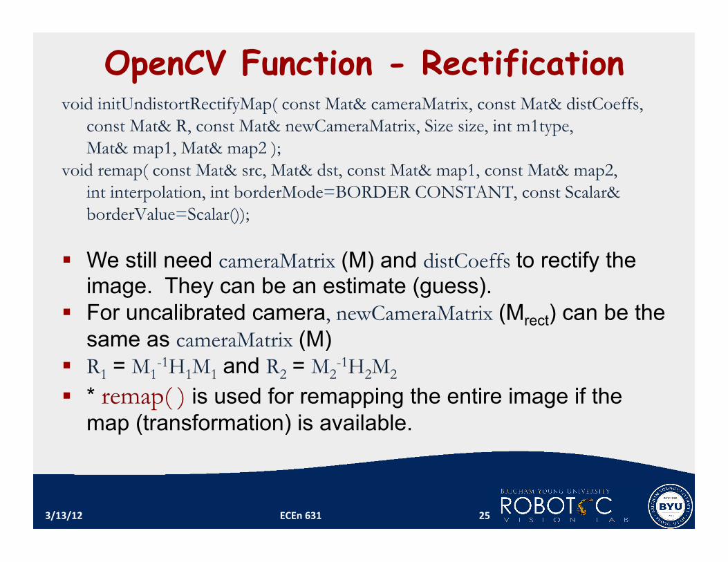
OpenCV Function - Rectification void initUndistortRectifyMap( const Mat& cameraMatrix, const Mat& distCoeffs,
const Mat& R, const Mat& newCameraMatrix, Size size, int m1type, Mat& map1, Mat& map2 );
void remap( const Mat& src, Mat& dst, const Mat& map1, const Mat& map2, int interpolation, int borderMode=BORDER CONSTANT, const Scalar& borderValue=Scalar());
We still need cameraMatrix (M) and distCoeffs to rectify the
image. They can be an estimate (guess). For uncalibrated camera, newCameraMatrix (Mrect) can be the
same as cameraMatrix (M) R1 = M1
-1H1M1 and R2 = M2-1H2M2
* remap( ) is used for remapping the entire image if the map (transformation) is available.
3/13/12 ECEn 631 25

Given a stereo pair of images, intrinsic parameters of each camera and extrinsic parameters of the stereo system – compute the transformation that makes epipolar lines parallel to the image horizontal axis.
The rectified images can be thought of as acquired by a new stereo rig, obtained by rotating the original cameras around their optical centers.
Attempts to minimize reprojection distortion
3/13/12 ECEn 631 26
Calibrated Stereo Rectification
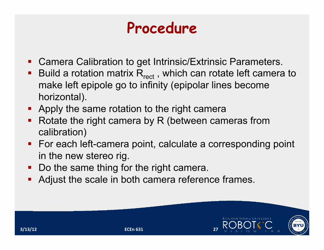
Procedure
Camera Calibration to get Intrinsic/Extrinsic Parameters. Build a rotation matrix Rrect , which can rotate left camera to
make left epipole go to infinity (epipolar lines become horizontal).
Apply the same rotation to the right camera Rotate the right camera by R (between cameras from
calibration) For each left-camera point, calculate a corresponding point
in the new stereo rig. Do the same thing for the right camera. Adjust the scale in both camera reference frames.
3/13/12 ECEn 631 27
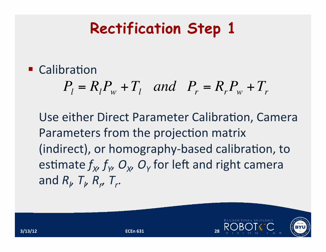
Rectification Step 1
Calibra1on Use either Direct Parameter Calibra1on, Camera Parameters from the projec1on matrix (indirect), or homography‐based calibra1on, to es1mate fX, fY, OX, OY for leG and right camera and Rl, Tl, Rr, Tr.
3/13/12 ECEn 631 28
!
Pl= R
lP
w+ T
l and P
r= R
rP
w+ T
r
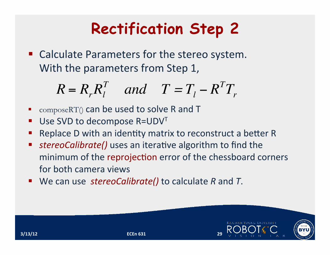
Rectification Step 2 Calculate Parameters for the stereo system. With the parameters from Step 1,
composeRT() can be used to solve R and T Use SVD to decompose R=UDVT Replace D with an iden1ty matrix to reconstruct a beYer R stereoCalibrate() uses an itera1ve algorithm to find the
minimum of the reprojec1on error of the chessboard corners for both camera views
We can use stereoCalibrate() to calculate R and T.
3/13/12 ECEn 631 29
!
R = RrR
l
T and T =T
l" R
TT
r

Rectification Step 3 Build the rota1on matrix Rrect for the leG camera so that the leG epipole goes to infinity and epipolar lines become horizontal
3/13/12 ECEn 631 30
TTe =1
Txy
yx
TTTT
e ]0,,[1222 −
+=
213 eee ×=
=T
T
T
rect
eee
R
3
2
1
A unit vector along the baseline
A normalized cross-product of e1 with the optical axis that is on the image plane
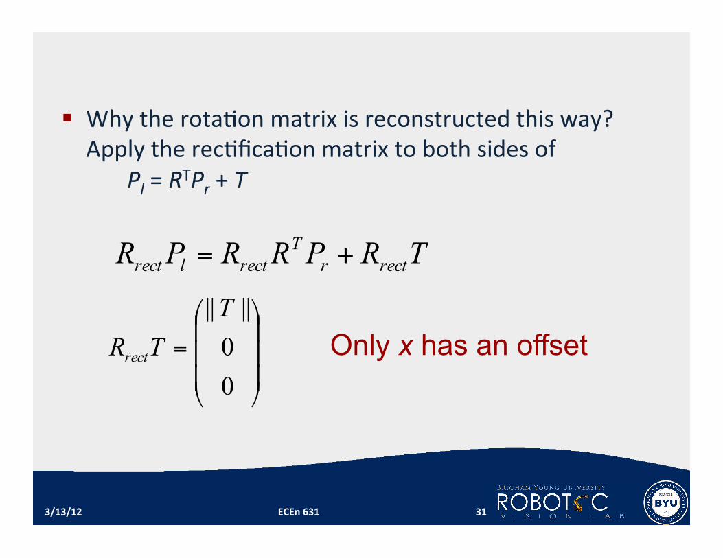
Why the rota1on matrix is reconstructed this way? Apply the rec1fica1on matrix to both sides of Pl = RTPr + T
TRPRRPR rectrT
rectlrect +=
=
00||||T
TRrect
3/13/12 ECEn 631 31
Only x has an offset
]',','['
'
]',','[],,[
zyxzfp
zyxpRfyxp
l
ll
Tl
=
=
=
!
Corresponding Rectified Point in pixel coordinates
sCoordinatecamera toscoordinate pixelConvert
Tl fyxp ],,[=
]',','['
' zyxzfp l =
'x
'z
!
x
3/13/12 ECEn 631 32
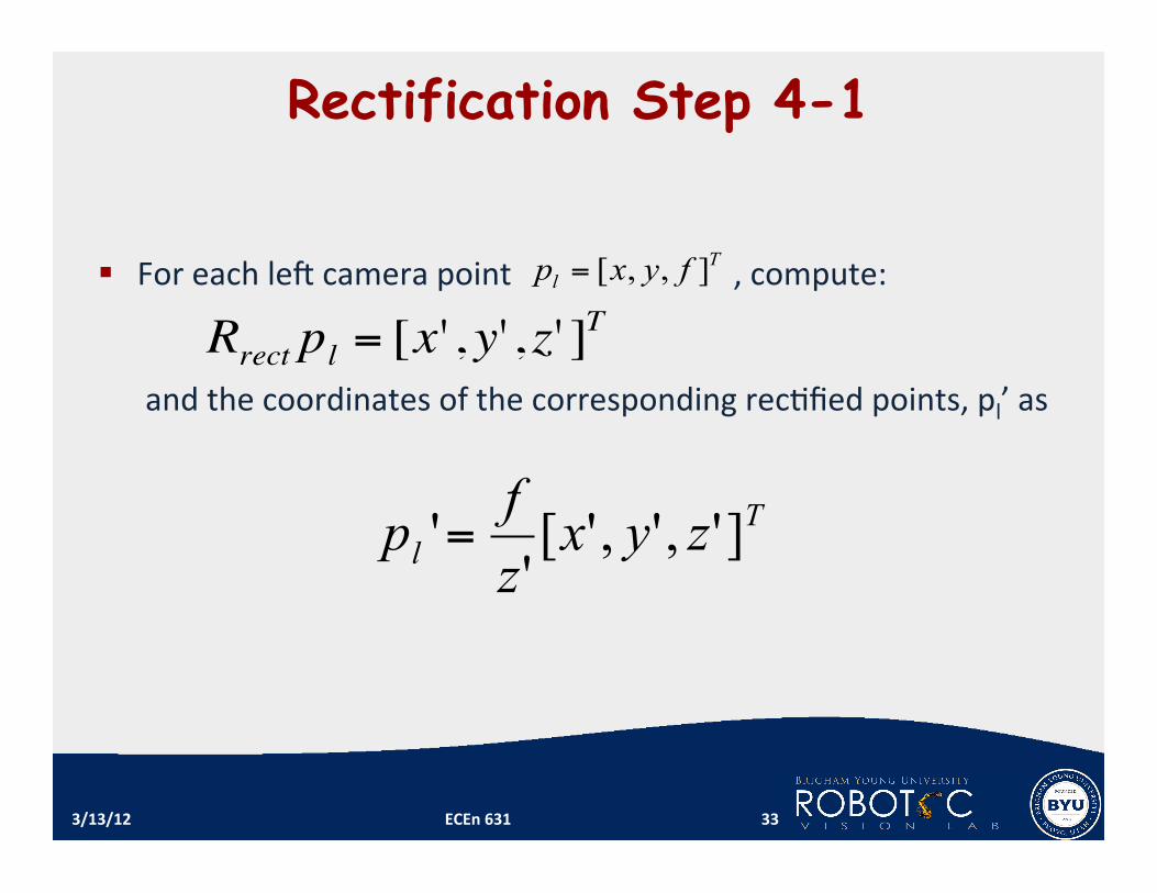
Rectification Step 4-1
For each leG camera point , compute:
and the coordinates of the corresponding rec1fied points, pl’ as
3/13/12 ECEn 631 33
Tl zyx
zfp ]',','['
'=
Tl fyxp ],,[=
!
Rrect pl = [x' , y' , z' ]T
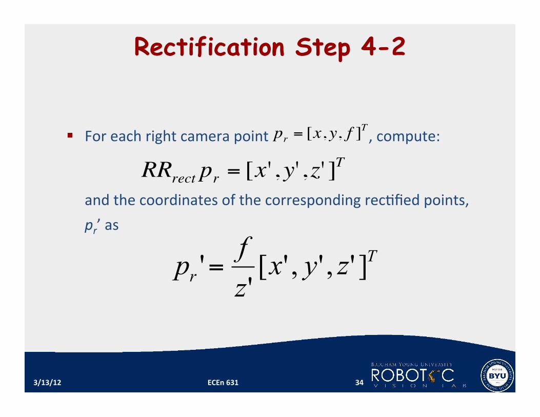
Rectification Step 4-2
3/13/12 ECEn 631 34
For each right camera point , compute:
and the coordinates of the corresponding rec1fied points, pr’ as
Tr zyx
zfp ]',','['
'=
!
pr = [x, y, f ]T
!
RRrect pr = [x' , y' , z' ]T
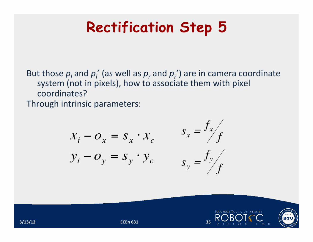
Rectification Step 5
But those pl and pl’ (as well as pr and pr’) are in camera coordinate system (not in pixels), how to associate them with pixel coordinates?
Through intrinsic parameters:
3/13/12 ECEn 631 35 !
xi " ox = sx # xc
yi " oy = sy # yc
!
sx =fx
f
sy =fy
f

Through Calibra1on, we have fX and fY ,but we don’t have f, what to do now? It cancels out, so we don’t really need it.
3/13/12 ECEn 631 36

Rectification Step 6
Perform the last step backwards, which means for each pixel in the rec1fied image, we need to find the correspondent point in the original image. The reason is that if we don’t do this, we will have a lot of holes in the rec1fied image.
3/13/12 ECEn 631 37
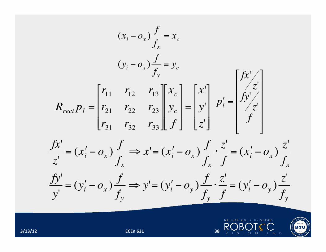
!
(xi " ox )f
f x= xc
(yi " ox )f
f y= yc
!
fx'
z'= ( " x i # ox )
f
f x
$ x'= ( " x i # ox )f
f x
%z'
f= ( " x i # ox )
z'
f x
fy'
y'= ( " y i # ox )
f
f y
$ y'= ( " y i # oy )f
f y
%z'
f= ( " y i # oy )
z'
f y
!
Rrect pl =
r11
r12
r13
r21
r22
r23
r31
r32
r33
"
#
$ $ $
%
&
' ' '
xc
yc
f
"
#
$ $ $
%
&
' ' '
=
x'
y'
z'
"
#
$ $ $
%
&
' ' '
!
" p l =
fx'z'
fy'z'
f
#
$
% % % %
&
'
( ( ( (
3/13/12 ECEn 631 38
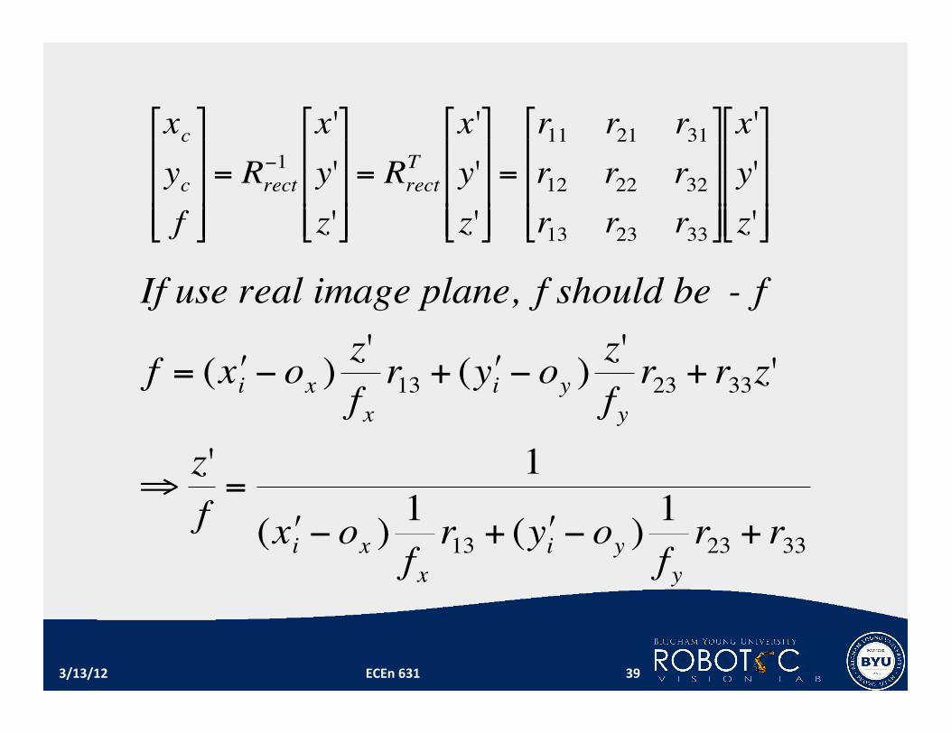
!
xc
yc
f
"
#
$ $ $
%
&
' ' '
= Rrect
(1
x'
y'
z'
"
#
$ $ $
%
&
' ' '
= Rrect
T
x'
y'
z'
"
#
$ $ $
%
&
' ' '
=
r11
r21
r31
r12
r22
r32
r13
r23
r33
"
#
$ $ $
%
&
' ' '
x'
y'
z'
"
#
$ $ $
%
&
' ' '
!
If use real image plane, f should be - f
f = ( " x i # ox )z'
f x
r13 + ( " y i # oy )z'
f y
r23 + r33z'
$z'
f=
1
( " x i # ox )1
f x
r13 + ( " y i # oy )1
f y
r23 + r33
3/13/12 ECEn 631 39

!
(xi " ox )f
f x
= xc = r11x'+r21y'+r31z'
= ( # x i " ox )z'
f x
r11 + ( # y i " oy )z'
f y
r21 + r31z'
!
(xi " ox ) = (x'i "ox )z'
f x
f x
fr11 + (y'i "oy )
z'
fy
f x
fr21 + r31
f x
fz'
# xi = (x'i "ox )z'
fr11 + (y'i "oy )
z'
f
fx
fyr21 " r31
z'
ff x + ox
3/13/12 ECEn 631 40
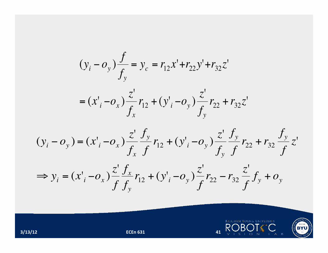
!
(yi " oy )f
f y= yc = r12x'+r22y'+r32z'
= (x'i "ox )z'
fxr12 + (y'i "oy )
z'
f yr22 + r32z'
!
(yi " oy ) = (x'i "ox )z'
f x
f y
fr12 + (y'i "oy )
z'
fy
f y
fr22 + r32
f y
fz'
# yi = (x'i "ox )z'
f
fx
fyr12 + (y'i "oy )
z'
fr22 " r32
z'
ff y + oy
3/13/12 ECEn 631 41
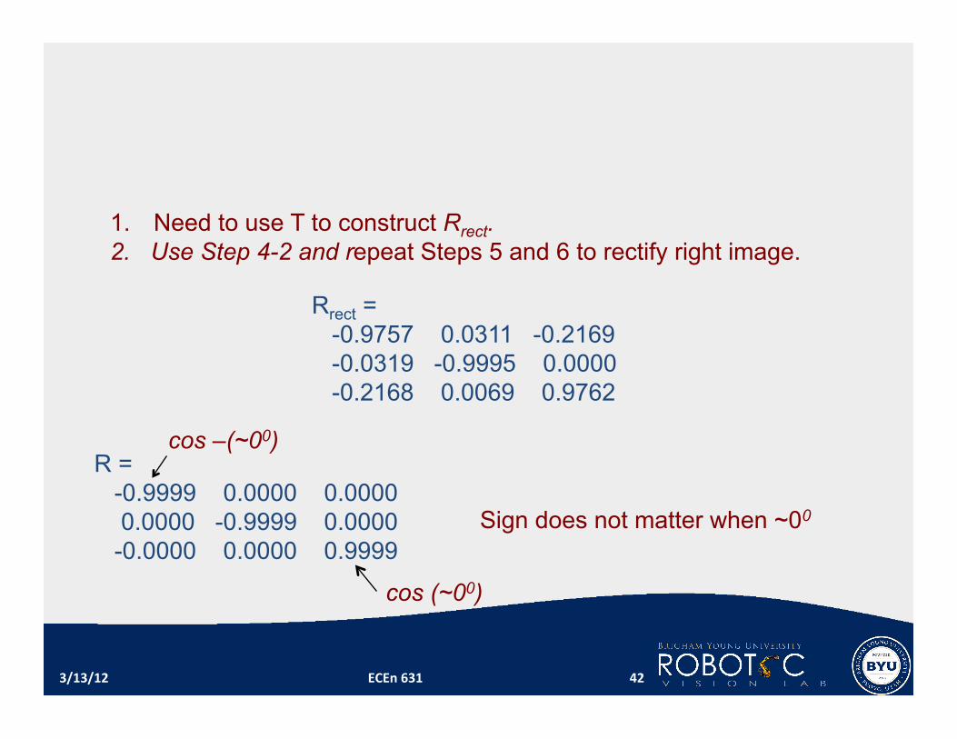
Rrect = -0.9757 0.0311 -0.2169 -0.0319 -0.9995 0.0000 -0.2168 0.0069 0.9762
1. Need to use T to construct Rrect. 2. Use Step 4-2 and repeat Steps 5 and 6 to rectify right image.
3/13/12 ECEn 631 42
R = -0.9999 0.0000 0.0000 0.0000 -0.9999 0.0000 -0.0000 0.0000 0.9999
cos (~00)
cos –(~00)
Sign does not matter when ~00
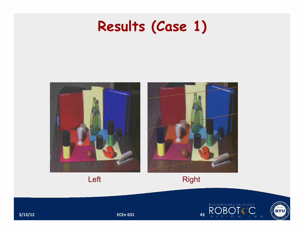
Results (Case 1)
3/13/12 ECEn 631 43
Left Right
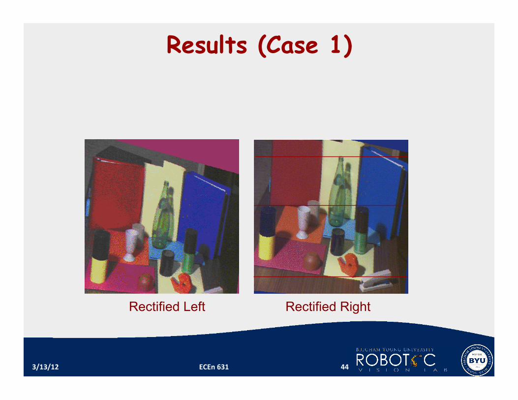
Results (Case 1)
3/13/12 ECEn 631 44
Rectified Left Rectified Right

OpenCV Function - Rectification
void stereoRectify( const Mat& cameraMatrix1, const Mat& distCoeffs1, const Mat& cameraMatrix2, const Mat& distCoeffs2, Size imageSize, const Mat& R, const Mat& T, Mat& R1, Mat& R2, Mat& P1, Mat& P2, Mat& Q, int flags=CALIB ZERO DISPARITY );
void stereoRectify( const Mat& cameraMatrix1, const Mat& distCoeffs1, const Mat& cameraMatrix2, const Mat& distCoeffs2, Size imageSize, const Mat& R, const Mat& T, Mat& R1, Mat& R2, Mat& P1, Mat& P2, Mat& Q, double alpha, Size newImageSize=Size(), Rect* roi1=0, Rect* roi2=0, int flags=CALIB ZERO DISPARITY );
stereoRectify() inputs 6 matrices from stereocalibrate() and
outputs 2 rotation matrices (R1 and R2), 2 projection matrices (P1 and P2), and one reprojection matrix Q.
Both stereoCalibrate() and stereoRectify() need only be done once.
3/13/12 ECEn 631 45
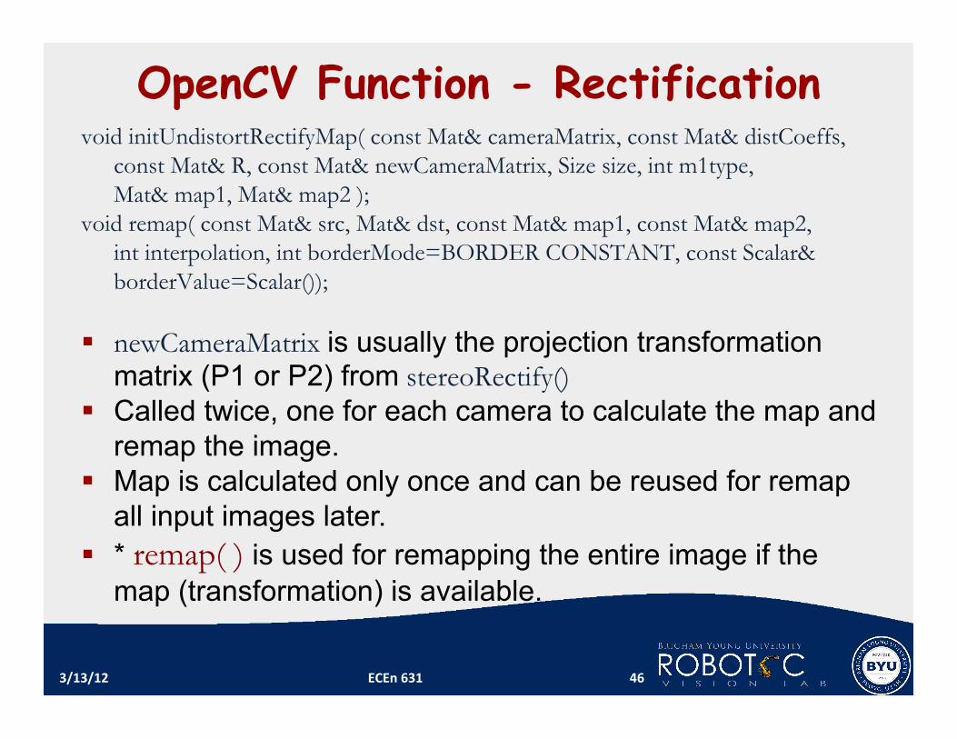
OpenCV Function - Rectification void initUndistortRectifyMap( const Mat& cameraMatrix, const Mat& distCoeffs,
const Mat& R, const Mat& newCameraMatrix, Size size, int m1type, Mat& map1, Mat& map2 );
void remap( const Mat& src, Mat& dst, const Mat& map1, const Mat& map2, int interpolation, int borderMode=BORDER CONSTANT, const Scalar& borderValue=Scalar());
newCameraMatrix is usually the projection transformation
matrix (P1 or P2) from stereoRectify() Called twice, one for each camera to calculate the map and
remap the image. Map is calculated only once and can be reused for remap
all input images later. * remap( ) is used for remapping the entire image if the
map (transformation) is available.
3/13/12 ECEn 631 46
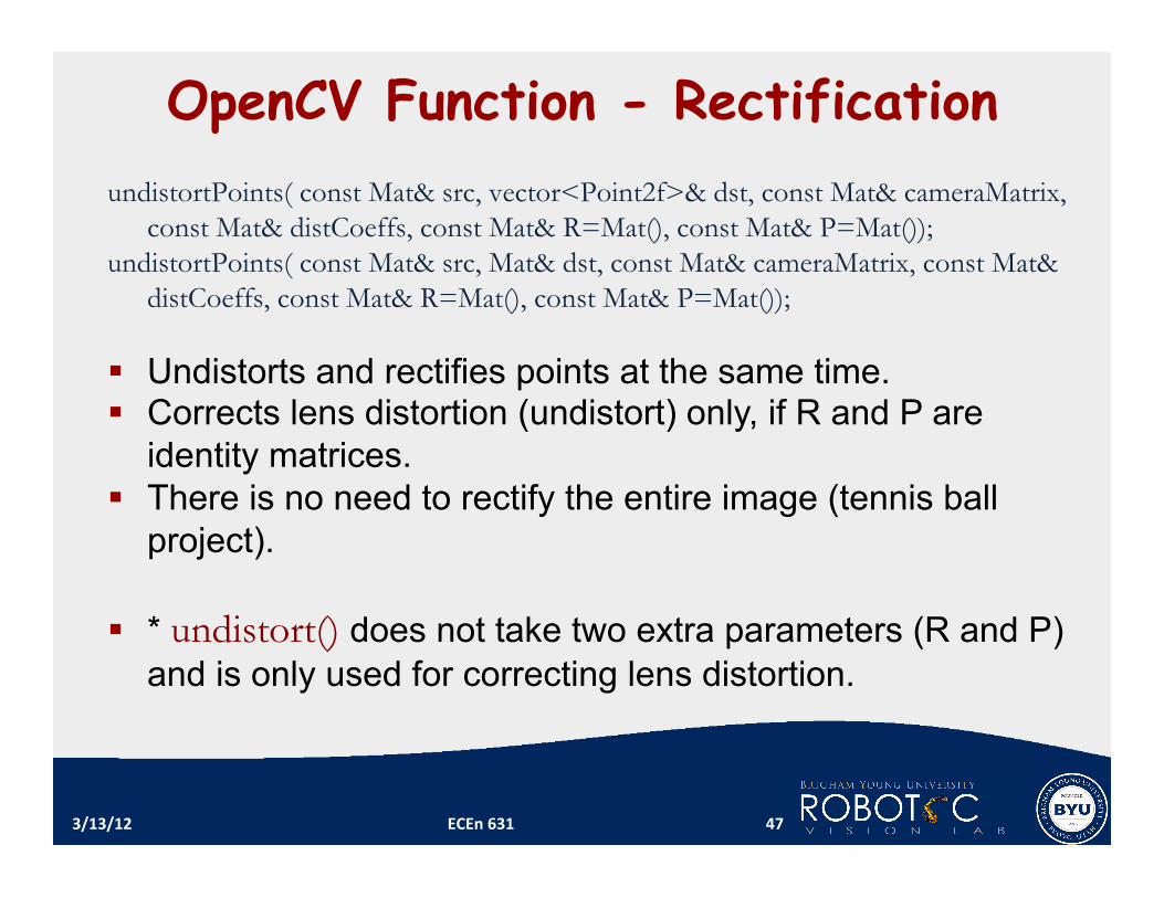
OpenCV Function - Rectification undistortPoints( const Mat& src, vector<Point2f>& dst, const Mat& cameraMatrix,
const Mat& distCoeffs, const Mat& R=Mat(), const Mat& P=Mat()); undistortPoints( const Mat& src, Mat& dst, const Mat& cameraMatrix, const Mat&
distCoeffs, const Mat& R=Mat(), const Mat& P=Mat()); Undistorts and rectifies points at the same time. Corrects lens distortion (undistort) only, if R and P are
identity matrices. There is no need to rectify the entire image (tennis ball
project).
* undistort() does not take two extra parameters (R and P) and is only used for correcting lens distortion.
3/13/12 ECEn 631 47
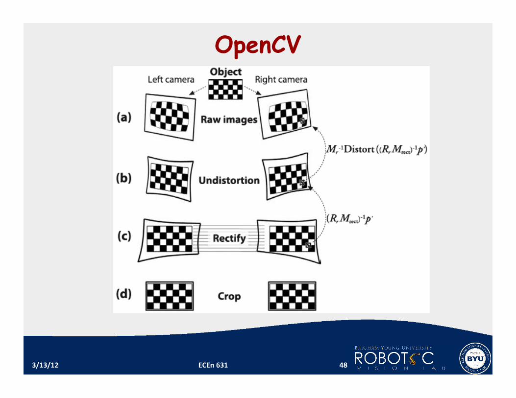
OpenCV
3/13/12 ECEn 631 48
3/13/12 ECEn 631 49


![El Destino de Diez [ECEN]](https://img.pdfslide.tips/doc/110x75/563db877550346aa9a93f1f9/el-destino-de-diez-ecen.jpg)