Embed Size (px)
Citation preview
June 2014 DocID026388 Rev 1 1/45
AN4499Application note
STM32 - nRF51822 Bluetooth Low Energy system solution
Introduction
The scope of this document is to describe the Bluetooth Low Energy (BLE) software (STSW-STM32149) implementation on the STM32L1 series and nRF51822 with the following features.
• Compatible with BLE profiles provided by Nordic
• Application integration ready
• Easy add-on of low power BLE solution on STM32L1 series
• Extremely low STM32L1 CPU load (HRS 1s update rate 0.065%)
• No latency requirements on STM32L1 series
• Small STM32L1 memory footprint
This document also describes how to interface to your own customer application and create your BLE services.
Customer application examples on STM32L1 using the Nordic BLE services are provided.
The reference hardware platform is based on the STM32Nucleo/64 and the Wavetek Bluetooth LE shield with Nordic BLE module nRF51822. The software supports the following list of products.
Note: It can be ported to other STM32 series.
Figure 1. STM32 Nordic nRF51822 BLE system solution
www.st.com
Contents AN4499
2/45 DocID026388 Rev 1
Contents
1 References . . . . . . . . . . . . . . . . . . . . . . . . . . . . . . . . . . . . . . . . . . . . . . . . . 6
2 Product definition . . . . . . . . . . . . . . . . . . . . . . . . . . . . . . . . . . . . . . . . . . . 7
3 Getting started . . . . . . . . . . . . . . . . . . . . . . . . . . . . . . . . . . . . . . . . . . . . . . 9
3.1 BLE system description . . . . . . . . . . . . . . . . . . . . . . . . . . . . . . . . . . . . . . . 9
3.2 Features . . . . . . . . . . . . . . . . . . . . . . . . . . . . . . . . . . . . . . . . . . . . . . . . . . . 9
3.3 Hardware/software quick setup . . . . . . . . . . . . . . . . . . . . . . . . . . . . . . . . 10
4 Reference platform . . . . . . . . . . . . . . . . . . . . . . . . . . . . . . . . . . . . . . . . . 12
4.1 Interface description . . . . . . . . . . . . . . . . . . . . . . . . . . . . . . . . . . . . . . . . . 12
4.2 UART 4-wire interface . . . . . . . . . . . . . . . . . . . . . . . . . . . . . . . . . . . . . . . 13
4.3 Reset system . . . . . . . . . . . . . . . . . . . . . . . . . . . . . . . . . . . . . . . . . . . . . . 13
4.3.1 Power on reset . . . . . . . . . . . . . . . . . . . . . . . . . . . . . . . . . . . . . . . . . . . 13
4.3.2 System reset . . . . . . . . . . . . . . . . . . . . . . . . . . . . . . . . . . . . . . . . . . . . . 13
4.4 Device programming . . . . . . . . . . . . . . . . . . . . . . . . . . . . . . . . . . . . . . . . 14
5 Software description . . . . . . . . . . . . . . . . . . . . . . . . . . . . . . . . . . . . . . . . 16
5.1 UART Interface . . . . . . . . . . . . . . . . . . . . . . . . . . . . . . . . . . . . . . . . . . . . . 16
5.1.1 BLE SD FW module . . . . . . . . . . . . . . . . . . . . . . . . . . . . . . . . . . . . . . . . 18
5.1.2 Low power manager . . . . . . . . . . . . . . . . . . . . . . . . . . . . . . . . . . . . . . . 18
5.1.3 Interrupt . . . . . . . . . . . . . . . . . . . . . . . . . . . . . . . . . . . . . . . . . . . . . . . . . 18
5.1.4 Context manager . . . . . . . . . . . . . . . . . . . . . . . . . . . . . . . . . . . . . . . . . . 18
5.1.5 Configuration . . . . . . . . . . . . . . . . . . . . . . . . . . . . . . . . . . . . . . . . . . . . . 19
5.1.6 STM32 resource requirements when BLE feature is used . . . . . . . . . . 19
5.1.7 Integration . . . . . . . . . . . . . . . . . . . . . . . . . . . . . . . . . . . . . . . . . . . . . . . 20
5.2 Timer interface . . . . . . . . . . . . . . . . . . . . . . . . . . . . . . . . . . . . . . . . . . . . . 20
5.2.1 BLE SD FW module . . . . . . . . . . . . . . . . . . . . . . . . . . . . . . . . . . . . . . . . 22
5.2.2 Initialization . . . . . . . . . . . . . . . . . . . . . . . . . . . . . . . . . . . . . . . . . . . . . . 22
5.2.3 User module . . . . . . . . . . . . . . . . . . . . . . . . . . . . . . . . . . . . . . . . . . . . . 23
5.2.4 Context manager . . . . . . . . . . . . . . . . . . . . . . . . . . . . . . . . . . . . . . . . . . 23
5.2.5 Configuration . . . . . . . . . . . . . . . . . . . . . . . . . . . . . . . . . . . . . . . . . . . . . 23
5.2.6 Integration . . . . . . . . . . . . . . . . . . . . . . . . . . . . . . . . . . . . . . . . . . . . . . . 24
5.3 NVM interface . . . . . . . . . . . . . . . . . . . . . . . . . . . . . . . . . . . . . . . . . . . . . . 24
DocID026388 Rev 1 3/45
AN4499 Contents
3
5.3.1 BLE SD FW module . . . . . . . . . . . . . . . . . . . . . . . . . . . . . . . . . . . . . . . . 26
5.3.2 Initialization . . . . . . . . . . . . . . . . . . . . . . . . . . . . . . . . . . . . . . . . . . . . . . 26
5.3.3 Operations . . . . . . . . . . . . . . . . . . . . . . . . . . . . . . . . . . . . . . . . . . . . . . . 27
5.3.4 Low power manager . . . . . . . . . . . . . . . . . . . . . . . . . . . . . . . . . . . . . . . 27
5.3.5 Configuration . . . . . . . . . . . . . . . . . . . . . . . . . . . . . . . . . . . . . . . . . . . . . 27
5.3.6 Integration . . . . . . . . . . . . . . . . . . . . . . . . . . . . . . . . . . . . . . . . . . . . . . . 28
5.4 Low power manager interface . . . . . . . . . . . . . . . . . . . . . . . . . . . . . . . . . 28
5.4.1 API . . . . . . . . . . . . . . . . . . . . . . . . . . . . . . . . . . . . . . . . . . . . . . . . . . . . . 30
5.4.2 Configuration . . . . . . . . . . . . . . . . . . . . . . . . . . . . . . . . . . . . . . . . . . . . . 30
5.4.3 Integration . . . . . . . . . . . . . . . . . . . . . . . . . . . . . . . . . . . . . . . . . . . . . . . 30
5.5 Exit from standby mode . . . . . . . . . . . . . . . . . . . . . . . . . . . . . . . . . . . . . . 30
5.6 BLE SD FW module firmware integration in application . . . . . . . . . . . . . . 31
5.6.1 BLE startup . . . . . . . . . . . . . . . . . . . . . . . . . . . . . . . . . . . . . . . . . . . . . . 31
5.6.2 Communication with the BLE SD FW module . . . . . . . . . . . . . . . . . . . . 31
5.7 Nordic delivery integration . . . . . . . . . . . . . . . . . . . . . . . . . . . . . . . . . . . . 32
6 BLE application configuration . . . . . . . . . . . . . . . . . . . . . . . . . . . . . . . 34
6.1 Architecture . . . . . . . . . . . . . . . . . . . . . . . . . . . . . . . . . . . . . . . . . . . . . . . 34
6.2 Direct test mode application . . . . . . . . . . . . . . . . . . . . . . . . . . . . . . . . . . . 35
6.3 Heart rate monitoring / Health thermometer application . . . . . . . . . . . . . . 35
6.3.1 Advertising application . . . . . . . . . . . . . . . . . . . . . . . . . . . . . . . . . . . . . . 36
6.3.2 Heart Rate application . . . . . . . . . . . . . . . . . . . . . . . . . . . . . . . . . . . . . . 36
6.3.3 Health thermomether application . . . . . . . . . . . . . . . . . . . . . . . . . . . . . . 37
7 Performances results . . . . . . . . . . . . . . . . . . . . . . . . . . . . . . . . . . . . . . . 38
7.1 Static power consumption . . . . . . . . . . . . . . . . . . . . . . . . . . . . . . . . . . . . 38
7.2 SD command exchange power consumption profile . . . . . . . . . . . . . . . . 38
7.3 Connection average power consumption . . . . . . . . . . . . . . . . . . . . . . . . . 39
7.4 Data throughput . . . . . . . . . . . . . . . . . . . . . . . . . . . . . . . . . . . . . . . . . . . . 41
8 System limitations . . . . . . . . . . . . . . . . . . . . . . . . . . . . . . . . . . . . . . . . . . 42
9 Revision history . . . . . . . . . . . . . . . . . . . . . . . . . . . . . . . . . . . . . . . . . . . 43
List of figures AN4499
4/45 DocID026388 Rev 1
List of figures
Figure 1. STM32 Nordic nRF51822 BLE system solution . . . . . . . . . . . . . . . . . . . . . . . . . . . . . . . . . . 1Figure 2. STM32 + nRF51822 system architecture . . . . . . . . . . . . . . . . . . . . . . . . . . . . . . . . . . . . . . . 8Figure 3. STM32 + nRF51822 HRM on Android . . . . . . . . . . . . . . . . . . . . . . . . . . . . . . . . . . . . . . . . 11Figure 4. HW platform stacking (Arduino signals) . . . . . . . . . . . . . . . . . . . . . . . . . . . . . . . . . . . . . . . 12Figure 5. nRF51822 - STM32 communication interface UART 4-wire. . . . . . . . . . . . . . . . . . . . . . . . 13Figure 6. STM32 programming with ST-LINK Utility . . . . . . . . . . . . . . . . . . . . . . . . . . . . . . . . . . . . . 14Figure 7. nRF51822 device programming . . . . . . . . . . . . . . . . . . . . . . . . . . . . . . . . . . . . . . . . . . . . . 15Figure 8. UART interface overview . . . . . . . . . . . . . . . . . . . . . . . . . . . . . . . . . . . . . . . . . . . . . . . . . . 17Figure 9. Timer interfaces overview. . . . . . . . . . . . . . . . . . . . . . . . . . . . . . . . . . . . . . . . . . . . . . . . . . 21Figure 10. Timer design overview . . . . . . . . . . . . . . . . . . . . . . . . . . . . . . . . . . . . . . . . . . . . . . . . . . . . 22Figure 11. NVM interfaces overview . . . . . . . . . . . . . . . . . . . . . . . . . . . . . . . . . . . . . . . . . . . . . . . . . . 25Figure 12. NVM design overview . . . . . . . . . . . . . . . . . . . . . . . . . . . . . . . . . . . . . . . . . . . . . . . . . . . . . 26Figure 13. Low power manager interfaces overview . . . . . . . . . . . . . . . . . . . . . . . . . . . . . . . . . . . . . . 28Figure 14. Low power manager design overview . . . . . . . . . . . . . . . . . . . . . . . . . . . . . . . . . . . . . . . . 29Figure 15. Scheduler implementation . . . . . . . . . . . . . . . . . . . . . . . . . . . . . . . . . . . . . . . . . . . . . . . . . 32Figure 16. Nordic delivery integration . . . . . . . . . . . . . . . . . . . . . . . . . . . . . . . . . . . . . . . . . . . . . . . . . 33Figure 17. Application overview . . . . . . . . . . . . . . . . . . . . . . . . . . . . . . . . . . . . . . . . . . . . . . . . . . . . . . 34Figure 18. Application DTM access . . . . . . . . . . . . . . . . . . . . . . . . . . . . . . . . . . . . . . . . . . . . . . . . . . . 35Figure 19. RxSD command exchange power consumption. . . . . . . . . . . . . . . . . . . . . . . . . . . . . . . . . 38Figure 20. TxSD command exchange power consumption . . . . . . . . . . . . . . . . . . . . . . . . . . . . . . . . . 39Figure 21. STM32 heart rate monitoring mobile notification . . . . . . . . . . . . . . . . . . . . . . . . . . . . . . . . 40
DocID026388 Rev 1 5/45
List of tables
5
List of tables
Table 1. STM32 memory footprint . . . . . . . . . . . . . . . . . . . . . . . . . . . . . . . . . . . . . . . . . . . . . . . . . . . 7Table 2. Interface between the STM32 and nRF51822 . . . . . . . . . . . . . . . . . . . . . . . . . . . . . . . . . . 12Table 3. Interface between the STM32 and Wavetek board . . . . . . . . . . . . . . . . . . . . . . . . . . . . . . 12Table 4. configuration of the BLE application . . . . . . . . . . . . . . . . . . . . . . . . . . . . . . . . . . . . . . . . . . 36Table 5. HRS profile average power consumption . . . . . . . . . . . . . . . . . . . . . . . . . . . . . . . . . . . . . . 41Table 6. Maximum data throughput L2CAP average power consumption . . . . . . . . . . . . . . . . . . . . 41Table 7. Document revision history . . . . . . . . . . . . . . . . . . . . . . . . . . . . . . . . . . . . . . . . . . . . . . . . . 43
References AN4499
6/45 DocID026388 Rev 1
1 References
[1] nRF51822 Soft Device specification, Nordic:
http://www.nordicsemi.com/
[2] nRF51822 Reference manual, Nordic:
http://www.nordicsemi.com/
[3] nRF51822 Product Specification, Nordic:
http://www.nordicsemi.com/
[4] Nordic Serializer project APIs
http://www.nordicsemi.com/
[5] STM32L151xx Reference Manual, ST:
http://www.st.com/
[6] STM32L15x Datasheet – Production data, ST:
http://www.st.com/
[7] STM32 Nucleo HW User Manual, ST
http://www.st.com/
[8] Wavetek Arduino Bluetooth LE shield UM, Wavetek
http://www.wavetek.com.hk
DocID026388 Rev 1 7/45
AN4499 Product definition
43
2 Product definition
The following firmware components are used:
• STM32 BLE application solution including the BLE SD FW Module
• nRF51822 S110 SoftDevice binary (see reference to Nordic documentation)
• nRF51822 connectivity serialized solution from Nordic (see reference to Nordic documentation)
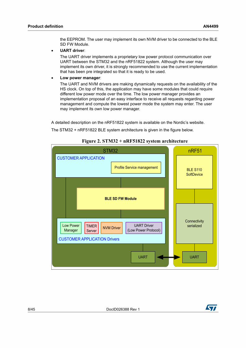
The STM32 + nRF51822 application provides a 2 chip BLE solution, where the STM32 operates as a host device and nRF51822 is the connectivity part.
In the STM32 + nRF51822 system the whole BLE stack is situated on the nRF51822 device, which interfaces to the STM32 via a UART.
The BLE SD FW module, UART, timer, NVM and the customer application are built on the STM32 platform. The customer application may be either a dedicated simple BLE application or a wider application on which BLE connectivity is added:
The following modules are required to add a BLE connectivity to the STM32:
• Profile service management :
The BLE services are running on the nRF51822 system and this module is providing an implementation proposal on the STM32 side to manage each supported BLE services. Although the implementation proposal is ready to be used, the user may implement its own services management.
• BLE SD FW module:
This module is not expected to be modified by the user. It provides an interface to the application to send and receive messages with the nRF51822 system. It requires from the STM32 platform a timer, a UART and a NVM.
• Timer server :
The Timer Server is an implementation proposal of a module that can provide multiple virtual timers all sharing the RTC Wakeup. The BLE Module gets a timer from that module to operate but the user may implement its own timer mechanism to be connected to the BLE Module.
• NVM driver:
The Non Volatile Memory driver is a very specific implementation proposal, using the EEPROM, suitable to be used by the BLE SD FW module. It provides an efficient mechanism to minimize the performance impact of the high latency required to write in
Table 1. STM32 memory footprint
ROM (Kbytes) RAM (Kbytes)
Full BLE SD FW Module
(When HRS application only)
31.3
(22.8)2.3
NVM driver, Timer server, UART driver, low power Manager
3.3 0.7
Product definition AN4499
8/45 DocID026388 Rev 1
the EEPROM. The user may implement its own NVM driver to be connected to the BLE SD FW Module.
• UART driver:
The UART driver implements a proprietary low power protocol communication over UART between the STM32 and the nRF51822 system. Although the user may implement its own driver, it is strongly recommended to use the current implementation that has been pre integrated so that it is ready to be used.
• Low power manager:
The UART and NVM drivers are making dynamically requests on the availability of the HS clock. On top of this, the application may have some modules that could require different low power mode over the time. The low power manager provides an implementation proposal of an easy interface to receive all requests regarding power management and compute the lowest power mode the system may enter. The user may implement its own low power manager.
A detailed description on the nRF51822 system is available on the Nordic’s website.
The STM32 + nRF51822 BLE system architecture is given in the figure below.
Figure 2. STM32 + nRF51822 system architecture
DocID026388 Rev 1 9/45
AN4499 Getting started
43
3 Getting started
3.1 BLE system description
By default the UART communication between the target MCU and ST-LINK MCU is enabled in order to support Virtual Com Port for mbed (SB13 and SB14 ON, SB62 and SB63 OFF).
As the communication between the target MCU and shield or extension board is required, SB62 and SB63 should be ON, SB13 and SB14 should be OFF.
The solution is composed of the following software items:
• STMicroelectronics BLE FW package: three pre-compiled applications
– stm_dtm_app.hex
– stm_hrs_app.hex
– stm_hts_app.hex
• nRF51822 SoftDevice binary (www.nordicsemi.com)
• s110_nrf51822_6.0.0_softdevice.hex
• nRF51822 serialized solution from Nordic (www.nordicsemi.com)
– ble_app_connectivity.hex
As the reference platform to run the previous software the following hardware items are used:
• 1 x STM32Nucleo/64 board revC with STM32L152RE
see Nucleo Rev C Hardware User manual [7] for more details
Note: By default the USART2 communication between the target MCU and ST-LINK MCU is enabled in order to support Virtual Com Port for mbed (SB13 and SB14 ON, SB62 and SB63 OFF). As the communication between the target MCU and shield or extension board is required, SB62 and SB63 should be ON, SB13 and SB14 should be OFF
• 1 x Wavetek Arduino shield with Nordic BLE module nRF51822
see Wavetek shield User Manual [8] for more details
Android Phone running STM32 BLE Toolbox can be used as demonstration tool.
• STM32_BLE_Toolbox.apk delivered with the solution
3.2 Features
The followings BLE services are supported with the system solution:
• Heart Rate service with Battery monitoring
• Health Thermometer service
• Direct Test Mode entry
• Advertiser Only
Getting started AN4499
10/45 DocID026388 Rev 1
3.3 Hardware/software quick setup
• Plug Wavetek Bluetooth LE shield on STM32Nucleo/64 board via the Arduino connectors. (See Figure at the front page 1)
• Connect the STM32 Nucleo/64 board to the PC with an USB cable (USB cable not provided)
• The PWD LED2 shall light up
• As pre-condition, the nRF51822 S110 Soft Device binary must be programmed. Refer to Nordic Quick Starter Guide documentation. (This part can’t be programmed with the ST-LINK)
• The nRF51822 needs to be programmed with the “Connectivity serialized” application.
• To program the “Connectivity serialized” via ST-LINK
– ST-LINK CN2 jumpers are OFF
– Wavetek Bluetooth LE shield RST J5&J6 Jumpers OFF
– Connect SWDCLK interface pin
STM32Nucleo/64 ST-LINK SWD CN4 pin 2 to Wavetek Bluetooth LE shield P1/JLINK SWDCLK pin4
– Connect SWDIO interface pin
STM32Nucleo/64 ST-LINK SWD CN4 pin4 to Wavetek Bluetooth LE shield J6.1
– Load “Connectivity” binary on nRF51822 with Keil™ or other tool
• Select BLE feature for STM32_ble_app” application
– Open “STM32_ble_app” project with MDK-ARM Microcontroller Development Kit by Keil™ or other tool
– Open stm32l1xx_conf.h to configure your project and compile.
• Program the STM32 with “STM32_ble_app” application
– Remove SWD interface connections between STM32Nucleo/64 ST-LINK and Wavetek Bluetooth LE shield
– ST-LINK CN2 jumpers are On
– Load “STM32L1_App_ble” binary on STM32 with Keil™ or other tool (STM32 ST-LINK Utility)
• Reset the System with Button Reset B2 on Nucleo Board.
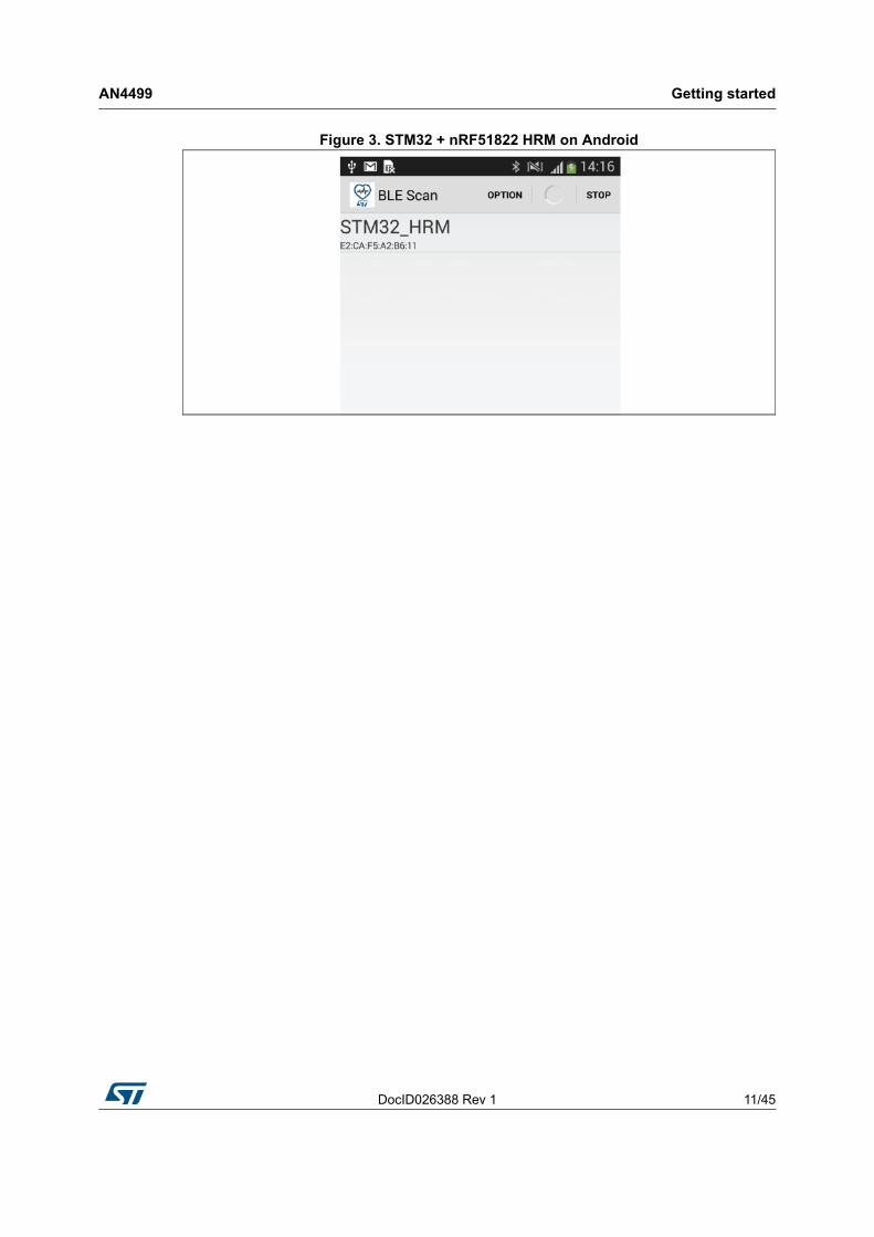
• BLE State is advertising
• Use Android or iPhone application to verify the advertiser packets
DocID026388 Rev 1 11/45
AN4499 Getting started
43
Figure 3. STM32 + nRF51822 HRM on Android
Reference platform AN4499
12/45 DocID026388 Rev 1
4 Reference platform
4.1 Interface description
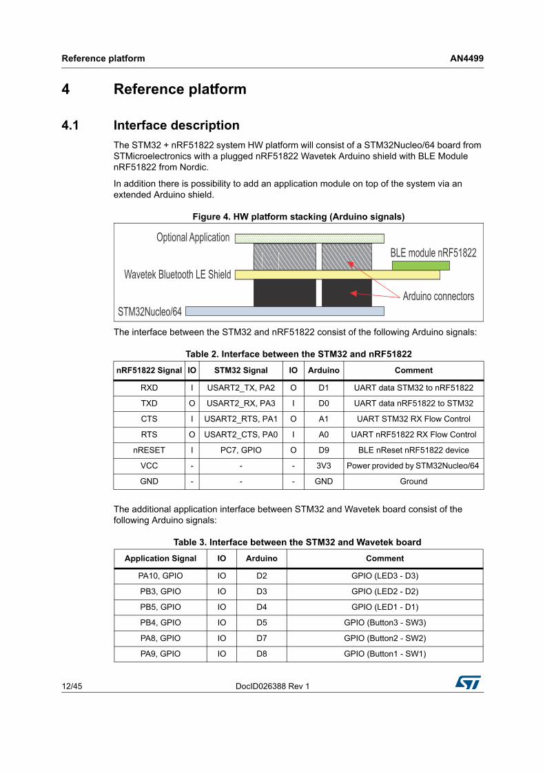
The STM32 + nRF51822 system HW platform will consist of a STM32Nucleo/64 board from STMicroelectronics with a plugged nRF51822 Wavetek Arduino shield with BLE Module nRF51822 from Nordic.
In addition there is possibility to add an application module on top of the system via an extended Arduino shield.
Figure 4. HW platform stacking (Arduino signals)
The interface between the STM32 and nRF51822 consist of the following Arduino signals:
The additional application interface between STM32 and Wavetek board consist of the following Arduino signals:
Table 2. Interface between the STM32 and nRF51822
nRF51822 Signal IO STM32 Signal IO Arduino Comment
RXD I USART2_TX, PA2 O D1 UART data STM32 to nRF51822
TXD O USART2_RX, PA3 I D0 UART data nRF51822 to STM32
CTS I USART2_RTS, PA1 O A1 UART STM32 RX Flow Control
RTS O USART2_CTS, PA0 I A0 UART nRF51822 RX Flow Control
nRESET I PC7, GPIO O D9 BLE nReset nRF51822 device
VCC - - - 3V3 Power provided by STM32Nucleo/64
GND - - - GND Ground
Table 3. Interface between the STM32 and Wavetek board
Application Signal IO Arduino Comment
PA10, GPIO IO D2 GPIO (LED3 - D3)
PB3, GPIO IO D3 GPIO (LED2 - D2)
PB5, GPIO IO D4 GPIO (LED1 - D1)
PB4, GPIO IO D5 GPIO (Button3 - SW3)
PA8, GPIO IO D7 GPIO (Button2 - SW2)
PA9, GPIO IO D8 GPIO (Button1 - SW1)
DocID026388 Rev 1 13/45
AN4499 Reference platform
43
4.2 UART 4-wire interface
The UART 4-wire interface is used to communicate between the 2 devices. The HW CTS/RTS flow control signals are also used for the low power control.
4.3 Reset system
The reset system can be divided into the following functions:
• Power on reset
• System reset
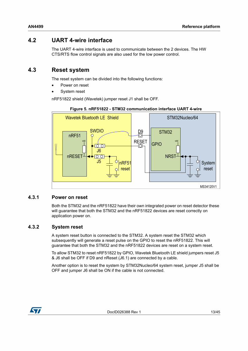
nRF51822 shield (Wavetek) jumper reset J1 shall be OFF.
Figure 5. nRF51822 - STM32 communication interface UART 4-wire
4.3.1 Power on reset
Both the STM32 and the nRF51822 have their own integrated power on reset detector these will guarantee that both the STM32 and the nRF51822 devices are reset correctly on application power on.
4.3.2 System reset
A system reset button is connected to the STM32. A system reset the STM32 which subsequently will generate a reset pulse on the GPIO to reset the nRF51822. This will guarantee that both the STM32 and the nRF51822 devices are reset on a system reset.
To allow STM32 to reset nRF51822 by GPIO, Wavetek Bluetooth LE shield jumpers reset J5 & J6 shall be OFF if D9 and nReset (J6.1) are connected by a cable.
Another option is to reset the system by STM32Nucleo/64 system reset, jumper J5 shall be OFF and jumper J6 shall be ON if the cable is not connected.
Reference platform AN4499
14/45 DocID026388 Rev 1
4.4 Device programming
The system solution provides FW download possibility through ST-LINK for both the STM32 and the nRF51822 serialized application. (The nRF51822 “Soft Device” can’t be loaded with the ST-LINK.)
See the STM32Nucleo/64 HW User Manual on how to program the software.
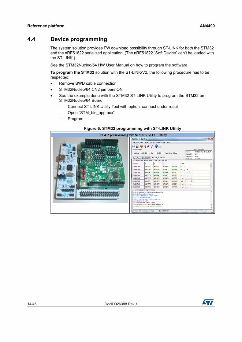
To program the STM32 solution with the ST-LINK/V2, the following procedure has to be respected:
• Remove SWD cable connection
• STM32Nucleo/64 CN2 jumpers ON
• See the example done with the STM32 ST-LINK Utility to program the STM32 on STM32Nucleo/64 Board
– Connect ST-LINK Utility Tool with option: connect under reset
– Open “STM_ble_app.hex”
– Program
Figure 6. STM32 programming with ST-LINK Utility
DocID026388 Rev 1 15/45
AN4499 Reference platform
43
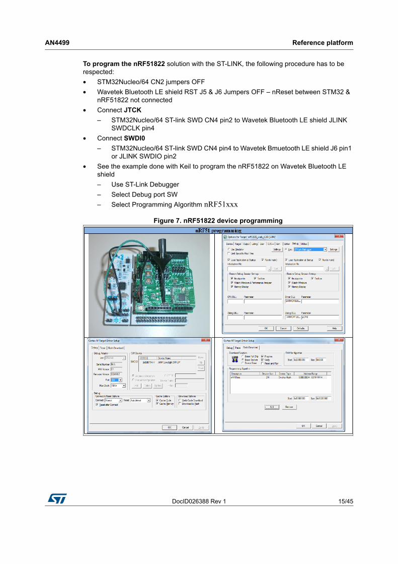
To program the nRF51822 solution with the ST-LINK, the following procedure has to be respected:
• STM32Nucleo/64 CN2 jumpers OFF
• Wavetek Bluetooth LE shield RST J5 & J6 Jumpers OFF – nReset between STM32 & nRF51822 not connected
• Connect JTCK
– STM32Nucleo/64 ST-link SWD CN4 pin2 to Wavetek Bluetooth LE shield JLINK SWDCLK pin4
• Connect SWDI0
– STM32Nucleo/64 ST-link SWD CN4 pin4 to Wavetek Bmuetooth LE shield J6 pin1 or JLINK SWDIO pin2
• See the example done with Keil to program the nRF51822 on Wavetek Bluetooth LE shield
– Use ST-Link Debugger
– Select Debug port SW
– Select Programming Algorithm nRF51xxx
Figure 7. nRF51822 device programming
Software description AN4499
16/45 DocID026388 Rev 1
5 Software description
This section provides a description of the interfaces of the different blocks shown in figure2 “STM32 + nRF51822 system architecture”:
• The interfaces between the BLE SD FW module and the STM32 peripherals (UART, Timer, NVM, Clocking)
• The interfaces between the BLE SD FW module and the application
• The project structure folder. It describes the split between the BLE SD FW module as such that does not require any modification by the application and the files that need to be adapted by the application.
Note: In the current delivery, the lowest low power mode supported when BLE is enabled is LP Stop. The application may enter Standby mode when BLE is not enabled.
Although it is described below in that chapter, there is no need for the application in the current delivery to:• Connect the UART CTS on the Wakeup pin
• Call the API HAL_UART_EnterStandByMode() when the device enters Standby mode
• Call the API HAL_UART_ExitStandByMode () when the device exits Standby mode
5.1 UART Interface
The BLE module sends and receives data over the UART interface. The UART driver provides a simple interface to send and receive messages and implements a proprietary protocol to notify the application when the UART may be disabled to enter low power mode.
DocID026388 Rev 1 17/45
AN4499 Software description
43
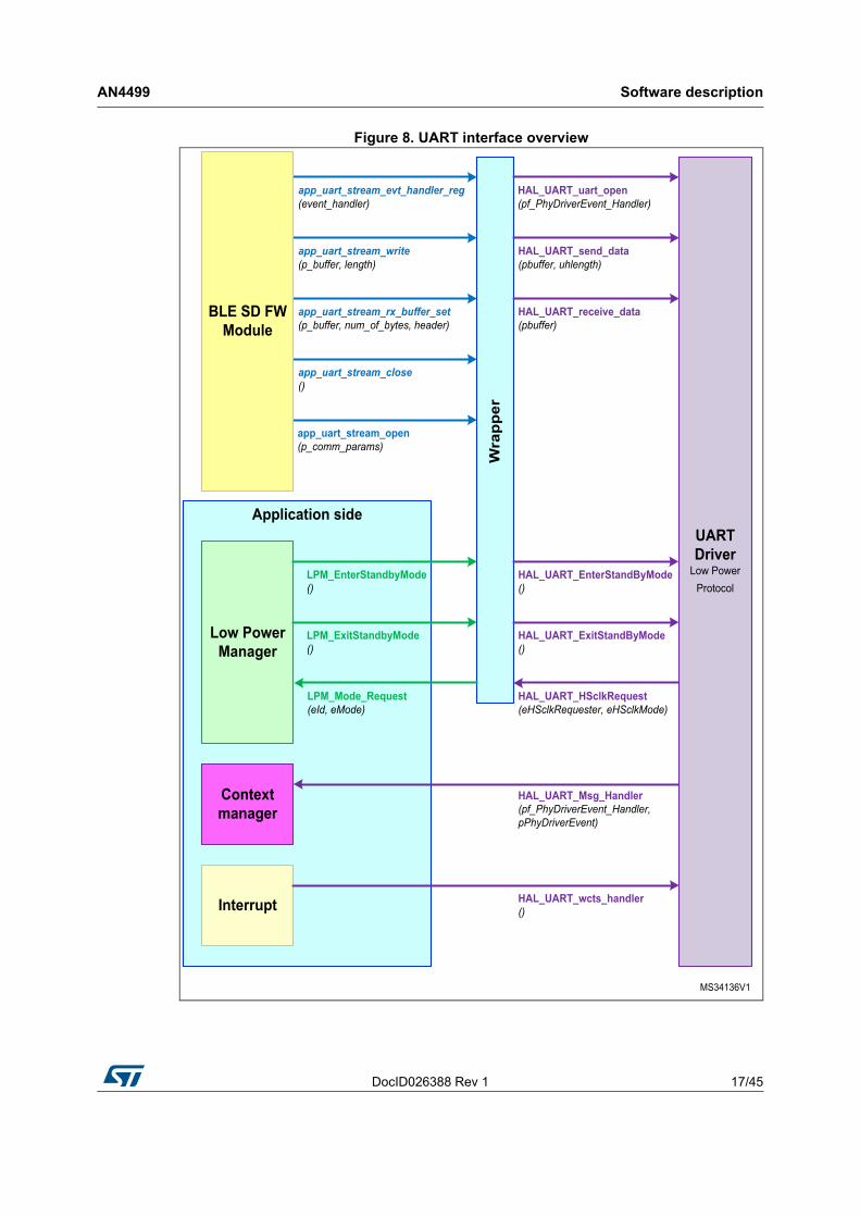
Figure 8. UART interface overview
Software description AN4499
18/45 DocID026388 Rev 1
5.1.1 BLE SD FW module
The following interfaces shall be mapped to the BLE module. They are not used by the application:
• HAL_UART_uart_open()
• HAL_UART_send_data()
• HAL_UART_receive_data()
As the mapping is not depending on the application but only on the BLE SD FW module interface, a default implementation is done in the file ble_uart.c.
There is no need for the application to make any modification.
5.1.2 Low power manager
• HAL_UART_EnterStandByMode()
• This API shall be called by the application before entering Standby mode
• HAL_UART_ExitStandByMode()
• This API shall be called by the application after the system did not succeed entering Standby mode. This is recovering the configuration before the HAL_UART_EnterStandByMode() has been called
• HAL_UART_HSclkRequest()
• This API is notifying the application when the HS clock may be stopped and when it shall be kept enabled. In addition, the application may switch ON the AHB DMA1 clock when the HS clock is requested and switch OFF the AHB DMA1 clock when the HS clocked is not required. This would save additional power when entering SLEEP mode.
5.1.3 Interrupt
• HAL_UART_wcts_handler()
This interrupt handler shall be called by the application in the EXTI15_10_IRQHandler() interrupt handler only when either USART1 or USART3 is used as interface with the connectivity device. When USART2 is selected, the UART driver is implementing the EXTI0_IRQHandler.
5.1.4 Context manager
• HAL_UART_Msg_Handler()
This API is notifying the BLE SD FW module that an event occurred on the UART interface. By default, all messages are handled in the UART interrupt context. The application may implement an Operating System to change the context priority where the BLE messages may be handled. A signal to the BLE task may be sent from this API to notify a full message has been received over UART.
DocID026388 Rev 1 19/45
AN4499 Software description
43
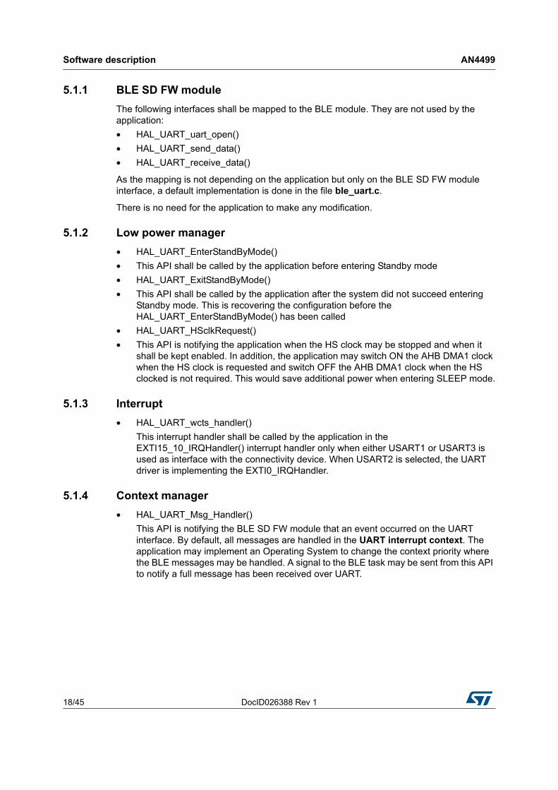
5.1.5 Configuration
The UART driver is fully configured in the file hal_uart_driver_configuration.h.
• The application may select to use USART1, USART2 or USART3 and chose the IO mapping. Default configuration is UART2 on PA0, PA1, PA2, and PA3.
• The application may change the UART baudrate. However, it is recommended to keep the default setting 1Mbits for power consumption optimization.
• The application may select which wakeup pin is used to get out of Standby mode on request from the nRF51822 connectivity device. Default is WakeupPin1. The wakeup pin selected shall be connected to the STM32 CTS line.
• The UART driver uses DMA, UART and EXTI interrupts. The priority set in the NVIC may be changed to allow the application to select the best priority with regard to already existing interrupts and timing requirement. The UART driver is able to run fine whatever priority is set. It is recommended to keep the same order as the default configuration which provides the best latency over UART. Default order is DMA (the highest), UART and EXTI (the lowest).
5.1.6 STM32 resource requirements when BLE feature is used
The UART driver requires some hardware resources that shall be made available before enabling the BLE feature. These hardware resources shall be kept enable as long as the BLE feature is enabled. The application should switch OFF all these hardware resources when BLE is disabled to save power.
The hardware resources concerned are:
• The GPIO AHB clock on which the UART is mapped from the file hal_uart_driver_configuration.h (GPIOxEN bit in the RCC_AHBENR register)
• The DMA1 AHB clock (DMA1EN bit in the RCC_AHBENR register)
• The DMA1 AHB clock in Sleep Mode (DMA1LPEN bit in the RCC_AHBLPENR register)
• The SRAM AHB clock in Sleep Mode (SRAMLPEN bit in the RCC_AHBLPENR register)
• The SYSCFG APB2 clock ((SYSCFGEN bit in the RCC_APB2ENR register)
• The PWR APB1 clock ((PWREN bit in the RCC_APB1ENR register)
• The APB clock of the USARTx selected in the file hal_uart_driver_configuration.h (USARTxEN bit in the RCC_APBxENR register)
• The APB clock in Sleep mode of the USARTx selected in the file hal_uart_driver_configuration.h (USARTxLPEN bit in the RCC_APBxLPENR register)
Software description AN4499
20/45 DocID026388 Rev 1
5.1.7 Integration
To include the UART low power driver in an existing application using BLE SD FW, the application shall:
1. Set the configuration required (USART, IOs, baudrate, wakeup pin and interrupt priority) in the file hal_uart_driver_configuration.h
2. Include the file hal_uart.c in the project
3. Map the UART BLE interface on the HAL UART driver (This step is already done in the wrapper implemented in the file ble_uart.c. The application may just include that file in the project)
4. Update the application low power manager to call the HAL_UART_EnterStandByMode() before entering standby mode (This step is done in the low power manager provided in the example). If standby mode is not supported in the application, there is nothing to do.
5. Update the application low power manager to call the HAL_UART_ExitStandByMode() when the CPU wakes up after failing entering standby mode (This step is done in the low power manager provided in the example). If standby mode is not supported in the application, there is nothing to do.
6. Implement the API HAL_UART_HSclkRequest() to handle the HS clock requirement and AHB DMA1 clock according to the low power UART driver activity.
7. When either USART1 or USART3 is selected, update the EXTI15_10_IRQHandler() to call the HAL_UART_wcts_handler() when the CTS line has triggered the interrupt. The . HAL_UART_wcts_handler() shall not be called if the CTS line is not the source that triggers the EXTI15_10_IRQHandler(). When USART2 is selected, there is nothing to do and the low power UART driver is taking care of it.
8. When an Operating System is used, the HAL_UART_Msg_Handler() may be used to send a signal with the associated parameter to handle the message in a different context than the UART interrupt. This API is executed within the UART interrupt handler context.
5.2 Timer interface
The BLE SD FW module uses a timer to timeout the connection parameters negotiations with the remote device. In order to save power consumption, this timer should be running on either the LSI or LSE LPO clock.
The timer server provides the following features:
• Up to 255 virtual timers ( or less due to RAM limitation)
• Single shot and Repeated mode
• Stop a virtual timer and restart it with a different timeout value
• Delete a timer
• Timeout up from 1 to 65535 ticks
The timer server provides multiple virtual timers sharing the Wakeup TIMER. Each virtual timer may be defined to be a single shot timer or a repeated timer. When a repeated timer elapses, the user is notified and the virtual timer is restarted automatically with the same timeout. When a single shot timer elapses, the user is notified and the virtual timer is set to the pending state. The user may stop a virtual timer and restart it with a different timeout
DocID026388 Rev 1 21/45
AN4499 Software description
43
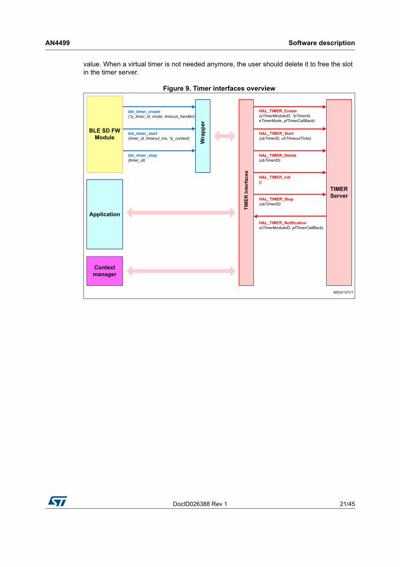
value. When a virtual timer is not needed anymore, the user should delete it to free the slot in the timer server.
Figure 9. Timer interfaces overview
Software description AN4499
22/45 DocID026388 Rev 1
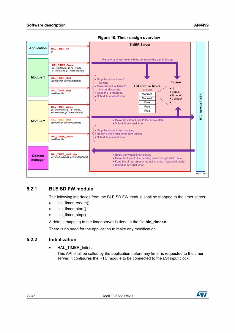
Figure 10. Timer design overview
5.2.1 BLE SD FW module
The following interfaces from the BLE SD FW module shall be mapped to the timer server:
• ble_timer_create()
• ble_timer_start()
• ble_timer_stop()
A default mapping to the timer server is done in the file ble_timer.c.
There is no need for the application to make any modification.
5.2.2 Initialization
• HAL_TIMER_Init() :
This API shall be called by the application before any timer is requested to the timer server. It configures the RTC module to be connected to the LSI input clock.
DocID026388 Rev 1 23/45
AN4499 Software description
43
5.2.3 User module
• HAL_TIMER_Create()
The user shall call this API to create a timer. Once created, the timer is reserved to the module until it has been deleted. When creating a timer, the user shall specify the mode (Single shot or Repeated), the Callback to be notified when the timer expires and a Module ID to identify in the timer interrupt handler which module is concerned.
In return, the User gets a timer ID to handle it.
• HAL_TIMER_Start()
This API shall be used to start a timer. The timeout value is specified and may be different each time.
When the timer is in the Single shot mode, it will move to the pending state when it expires. The user may restart it at any time with a different timeout value
When the timer is in the Repeated mode, it always stay in the running state. When the timer expires, it will be restarted with the same timeout value.
This API shall not be called on a running timer.
• HAL_TIMER_Stop()
This API may be used to stop a running timer. A timer which is stopped is move to the pending state.
A pending timer may be restarted at any time with a different timeout value but the mode cannot be changed.
• HAL_TIMER_Delete()
This API should be used when a timer is not needed anymore by the user. A deleted timer is removed from the timer list managed by the timer server. It cannot be restarted again. The user has to go with the creation of a new timer if required and may get a different timer id.
5.2.4 Context manager
• HAL_TIMER_Notification ()
This API notifies the application that a timer expires. This API is running in the RTC Wakeup interrupt context. The application may implement an Operating System to change the context priority where the timer Callback may be handled. This API provides the module ID to identify which module is concerned and to allow sending the information to the correct task.
5.2.5 Configuration
Some parameters of the Timer server may be configured in the file hal_timer.h.
• MAX_NBR_CONCURRENT_TIMER: The user may define the maximum number of virtual timer supported. It shall not exceed 255. Default configuration is 8
• NVIC_UART_RTC_WAKEUP_IT_PRIORITY: The user may define the priority in the NVIC of the RTC_WKUP interrupt handler that is used to manage the wakeup timer. Default configuration is 3.
• eHAL_TIMER_ModuleID_t: The user shall define the list of Module Id that the timer server shall support.
Software description AN4499
24/45 DocID026388 Rev 1
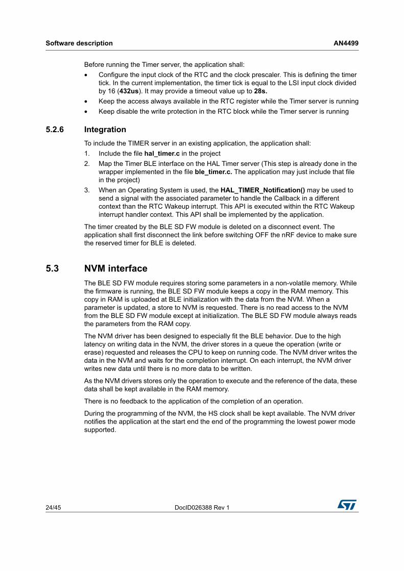
Before running the Timer server, the application shall:
• Configure the input clock of the RTC and the clock prescaler. This is defining the timer tick. In the current implementation, the timer tick is equal to the LSI input clock divided by 16 (432us). It may provide a timeout value up to 28s.
• Keep the access always available in the RTC register while the Timer server is running
• Keep disable the write protection in the RTC block while the Timer server is running
5.2.6 Integration
To include the TIMER server in an existing application, the application shall:
1. Include the file hal_timer.c in the project
2. Map the Timer BLE interface on the HAL Timer server (This step is already done in the wrapper implemented in the file ble_timer.c. The application may just include that file in the project)
3. When an Operating System is used, the HAL_TIMER_Notification() may be used to send a signal with the associated parameter to handle the Callback in a different context than the RTC Wakeup interrupt. This API is executed within the RTC Wakeup interrupt handler context. This API shall be implemented by the application.
The timer created by the BLE SD FW module is deleted on a disconnect event. The application shall first disconnect the link before switching OFF the nRF device to make sure the reserved timer for BLE is deleted.
5.3 NVM interface
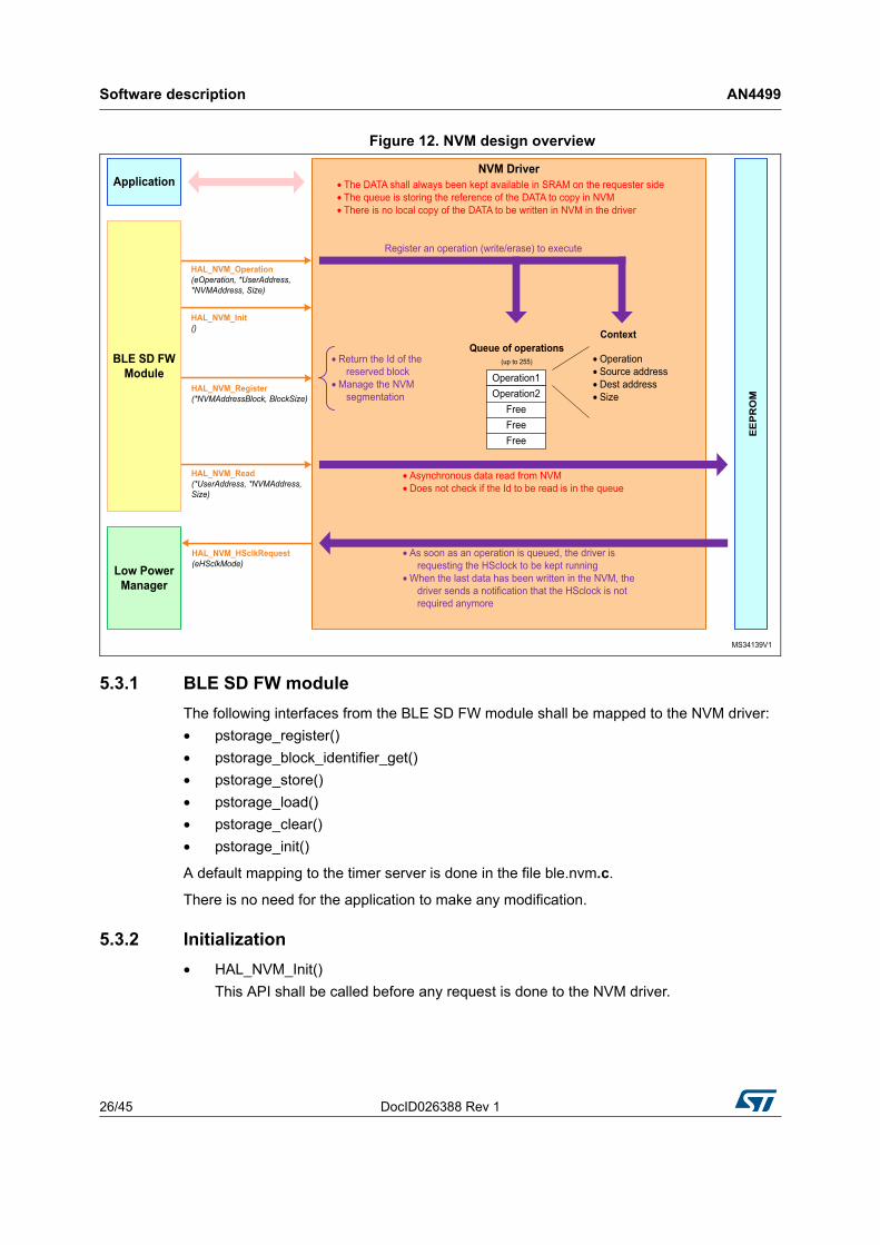
The BLE SD FW module requires storing some parameters in a non-volatile memory. While the firmware is running, the BLE SD FW module keeps a copy in the RAM memory. This copy in RAM is uploaded at BLE initialization with the data from the NVM. When a parameter is updated, a store to NVM is requested. There is no read access to the NVM from the BLE SD FW module except at initialization. The BLE SD FW module always reads the parameters from the RAM copy.
The NVM driver has been designed to especially fit the BLE behavior. Due to the high latency on writing data in the NVM, the driver stores in a queue the operation (write or erase) requested and releases the CPU to keep on running code. The NVM driver writes the data in the NVM and waits for the completion interrupt. On each interrupt, the NVM driver writes new data until there is no more data to be written.
As the NVM drivers stores only the operation to execute and the reference of the data, these data shall be kept available in the RAM memory.
There is no feedback to the application of the completion of an operation.
During the programming of the NVM, the HS clock shall be kept available. The NVM driver notifies the application at the start end the end of the programming the lowest power mode supported.
DocID026388 Rev 1 25/45
AN4499 Software description
43
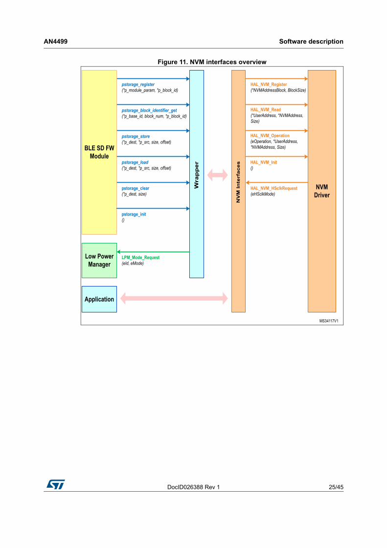
Figure 11. NVM interfaces overview
Software description AN4499
26/45 DocID026388 Rev 1
Figure 12. NVM design overview
5.3.1 BLE SD FW module
The following interfaces from the BLE SD FW module shall be mapped to the NVM driver:
• pstorage_register()
• pstorage_block_identifier_get()
• pstorage_store()
• pstorage_load()
• pstorage_clear()
• pstorage_init()
A default mapping to the timer server is done in the file ble.nvm.c.
There is no need for the application to make any modification.
5.3.2 Initialization
• HAL_NVM_Init()
This API shall be called before any request is done to the NVM driver.
DocID026388 Rev 1 27/45
AN4499 Software description
43
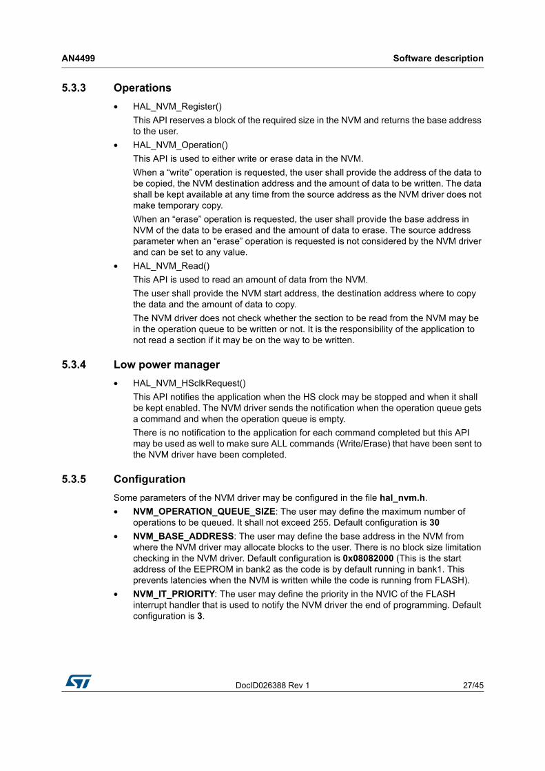
5.3.3 Operations
• HAL_NVM_Register()
This API reserves a block of the required size in the NVM and returns the base address to the user.
• HAL_NVM_Operation()
This API is used to either write or erase data in the NVM.
When a “write” operation is requested, the user shall provide the address of the data to be copied, the NVM destination address and the amount of data to be written. The data shall be kept available at any time from the source address as the NVM driver does not make temporary copy.
When an “erase” operation is requested, the user shall provide the base address in NVM of the data to be erased and the amount of data to erase. The source address parameter when an “erase” operation is requested is not considered by the NVM driver and can be set to any value.
• HAL_NVM_Read()
This API is used to read an amount of data from the NVM.
The user shall provide the NVM start address, the destination address where to copy the data and the amount of data to copy.
The NVM driver does not check whether the section to be read from the NVM may be in the operation queue to be written or not. It is the responsibility of the application to not read a section if it may be on the way to be written.
5.3.4 Low power manager
• HAL_NVM_HSclkRequest()
This API notifies the application when the HS clock may be stopped and when it shall be kept enabled. The NVM driver sends the notification when the operation queue gets a command and when the operation queue is empty.
There is no notification to the application for each command completed but this API may be used as well to make sure ALL commands (Write/Erase) that have been sent to the NVM driver have been completed.
5.3.5 Configuration
Some parameters of the NVM driver may be configured in the file hal_nvm.h.
• NVM_OPERATION_QUEUE_SIZE: The user may define the maximum number of operations to be queued. It shall not exceed 255. Default configuration is 30
• NVM_BASE_ADDRESS: The user may define the base address in the NVM from where the NVM driver may allocate blocks to the user. There is no block size limitation checking in the NVM driver. Default configuration is 0x08082000 (This is the start address of the EEPROM in bank2 as the code is by default running in bank1. This prevents latencies when the NVM is written while the code is running from FLASH).
• NVM_IT_PRIORITY: The user may define the priority in the NVIC of the FLASH interrupt handler that is used to notify the NVM driver the end of programming. Default configuration is 3.
Software description AN4499
28/45 DocID026388 Rev 1
5.3.6 Integration
To include the NVM driver, the application shall:
1. Set the configuration required in the file hal_timer.h
2. Include the file hal_nvm.c in the project
3. Map the pstorage BLE interface on the HAL NVM driver (This step is already done in the wrapper implemented in the file ble.nvm.c. The application may just include that file in the project)
4. Implement the API HAL_NVM_HSclkRequest() to handle the HS clock requirement according to the NVM driver activity.
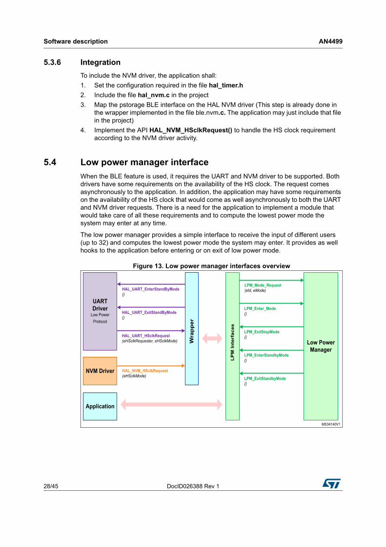
5.4 Low power manager interface
When the BLE feature is used, it requires the UART and NVM driver to be supported. Both drivers have some requirements on the availability of the HS clock. The request comes asynchronously to the application. In addition, the application may have some requirements on the availability of the HS clock that would come as well asynchronously to both the UART and NVM driver requests. There is a need for the application to implement a module that would take care of all these requirements and to compute the lowest power mode the system may enter at any time.
The low power manager provides a simple interface to receive the input of different users (up to 32) and computes the lowest power mode the system may enter. It provides as well hooks to the application before entering or on exit of low power mode.
Figure 13. Low power manager interfaces overview
DocID026388 Rev 1 29/45
AN4499 Software description
43
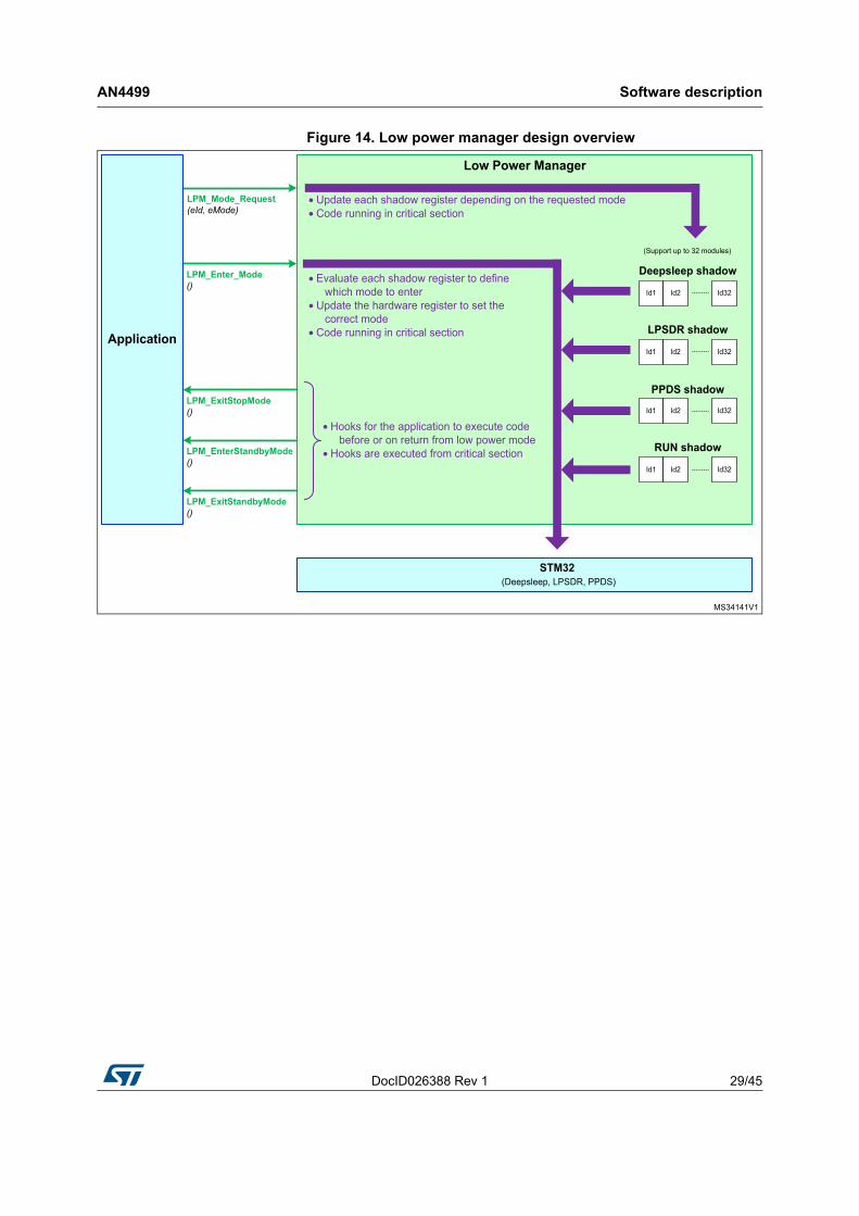
Figure 14. Low power manager design overview
Software description AN4499
30/45 DocID026388 Rev 1
5.4.1 API
• LPM_Mode_Request()
This API shall be used by all users to specify the lowest low power mode it supports.
• LPM_Enter_Mode()
This API shall be used by the application when there is no more code to execute so that the system may enter low power mode.
• LPM_ExitStopMode()
This API is called by the low power manager in a critical section (PRIMASK bit set) to allow the application to implement dedicated code before getting out from the critical section.
This is the location where the application should reconfigure the clock tree as the system gets out from Stop mode with the MSI clock selected as source clock.
• LPM_EnterStandbyMode()
This API is called by the low power manager in a critical section (PRIMASK bit set) to allow the application to implement dedicated code before entering standby mode.
This is the location where the application could save data in the retention memory as the RAM memory content will be lost.
• LPM_ExitStandbyMode()
This API is called by the low power manager in a critical section (PRIMASK bit set) to allow the application to implement dedicated code before getting out from Standby mode.
This can only happen when the Standby mode is finally not entered. In that case, the application may reverse some configurations done before entering Standby mode. When Standby mode is successful, the system is reset when getting out from this low power mode.
5.4.2 Configuration
The application shall configure in the file stm32l1xx_lpm.h the Id for each user supported and the list of low power mode supported.
The default lowest power mode supported for all users is Standby mode.
5.4.3 Integration
To include the low power manager driver, the application shall:
1. Set the configuration required in the file stm32l1xx_lpm.h
2. Include the file stm32l1xx_lpm.c in the project.
5.5 Exit from standby mode
The user may select in the UART configuration which Wakeup pin to use to exit standby mode on request of the nRF51822 system. When several Wakeup pins are configured on the STM32 system, the application shall manage the other wakeup pins. The wakeup pin selected for the BLE feature is fully managed by the UART driver and the application does not need to implement dedicated code for this.
DocID026388 Rev 1 31/45
AN4499 Software description
43
5.6 BLE SD FW module firmware integration in application
The STM32_ble_app project provides an application using the BLE SD FW module based on a scheduler. It comes with a Timer server, NVM driver and low power protocol UART driver to interface with the STM32 platform. Whenever the BLE function is enabled, the STM32 shall not enter standby mode, the application shall take care that STOP mode is the lowest low power mode used.
The user may either implement its own services or integrate those which are provided in the project.
5.6.1 BLE startup
When the nRF device is in OFF mode, the application shall execute following steps to get BLE ready to be used:
1. Enable the TIMER and NVM services.
The NVM driver is enabled at the same time the BLE SD FW module is initialized. There is no additional implementation required in the application
To enable the timer server, the application shall called the API HAL_TIMER_Init().
2. Enable hardware resources required for the BLE low power protocol UART driver
All resources as described in “6.1.6 STM32 resource requirements when BLE feature is used” are enabled in the API UART_BLE_Init(). The user may update the content of this API depending on its own implementation.
3. Reset and initialize the nRF device
The nRF device shall be first reset before running any initialization. The reset is applied when the API connectivity_chip_reset() is called. The firmware drives low the IO connected to the nRF nRESET pin for a minimum amount of time. After that time, the firmware configures the IO to analog mode to release the nRF nRESET pin. The nRF nRESET pin should not be driven high to release the reset. The reset timing requirement may be found on the Nordic website.
After the nRF device has been reset, the firmware runs the nRF initialization with the API ble_app_main_init_Reset(). All details on the nRF initialization may be found on the Nordic website.
5.6.2 Communication with the BLE SD FW module
The application sends requests or data to the BLE SD FW module with a SD command.
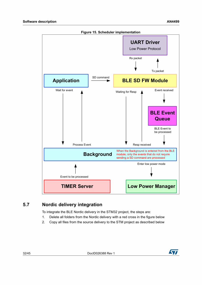
When a SD command is sent, the application shall wait for the response before sending another SD command. On each SD command, the BLE SD FW module calls the API blocking_resp_wait() to pause the BLE processing until the response is received. The application may enter low power mode until the response is received. In addition, all events that do not require sending a SD command may be processed as well over that time.
As described below, the current project provides a scheduler where the API blocking_resp_wait() is implemented in the file blocking.c to enter the background task when waiting for a response. When the firmware enters the background task from the BLE SD FW module, all events that do not require sending a SD command are processed.
Software description AN4499
32/45 DocID026388 Rev 1
Figure 15. Scheduler implementation
5.7 Nordic delivery integration
To integrate the BLE Nordic delivery in the STM32 project, the steps are:
1. Delete all folders from the Nordic delivery with a red cross in the figure below
2. Copy all files from the source delivery to the STM project as described below
DocID026388 Rev 1 33/45
AN4499 Software description
43
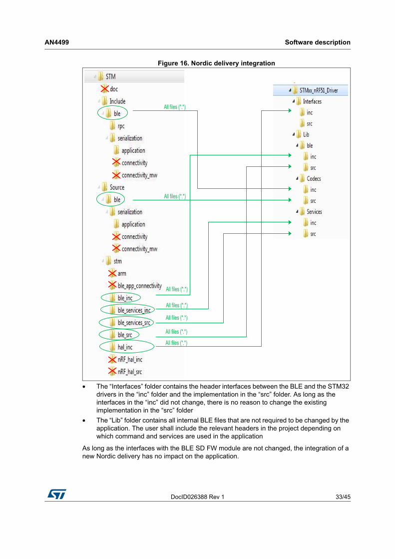
Figure 16. Nordic delivery integration
• The “Interfaces” folder contains the header interfaces between the BLE and the STM32 drivers in the “inc” folder and the implementation in the “src” folder. As long as the interfaces in the “inc” did not change, there is no reason to change the existing implementation in the “src” folder
• The “Lib” folder contains all internal BLE files that are not required to be changed by the application. The user shall include the relevant headers in the project depending on which command and services are used in the application
As long as the interfaces with the BLE SD FW module are not changed, the integration of a new Nordic delivery has no impact on the application.
BLE application configuration AN4499
34/45 DocID026388 Rev 1
6 BLE application configuration
The Nordic nRF51822 SDK provides examples how to manage the different profiles and Services.
To allow customers to verify BLE profiles and services, two applications are available in the STM32 “Project” directory:
• Direct Test Mode application
– “STM_dtm_app” project
• Heart Rate Monitoring/Health Thermometer application
– “STM_ble_app” project
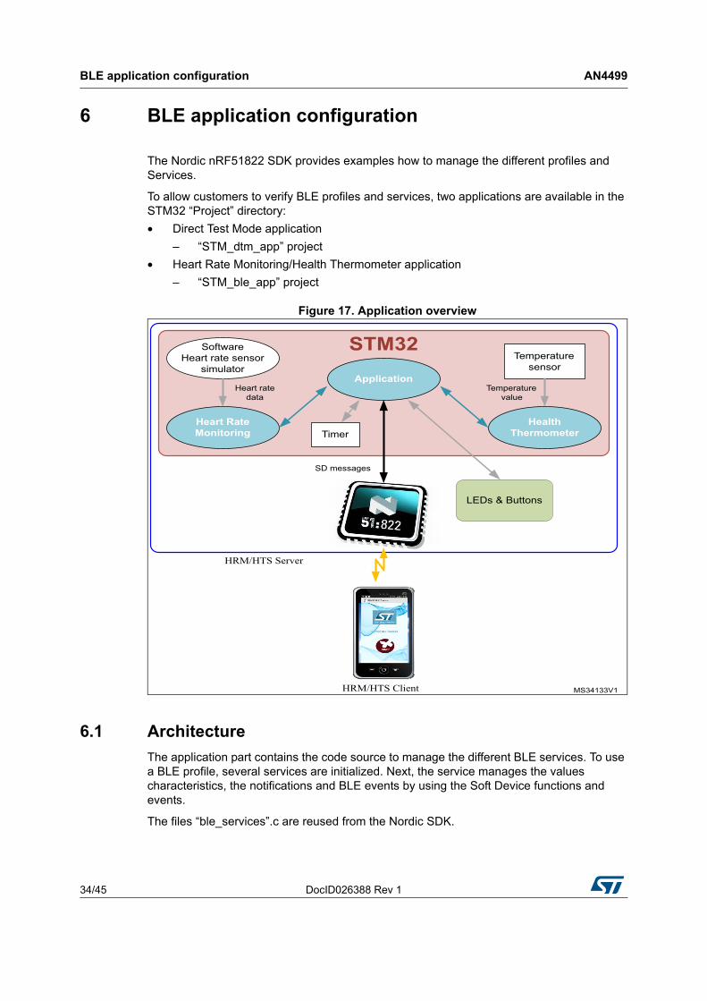
Figure 17. Application overview
6.1 Architecture
The application part contains the code source to manage the different BLE services. To use a BLE profile, several services are initialized. Next, the service manages the values characteristics, the notifications and BLE events by using the Soft Device functions and events.
The files “ble_services”.c are reused from the Nordic SDK.
DocID026388 Rev 1 35/45
AN4499 BLE application configuration
43
6.2 Direct test mode application
The Direct Test Mode application is a firmware example that manages to initialize the nRF51822 to enter Direct Test Mode and redirect the nRF51822 UART to the tester.
• Project : STM_dtm_app
To initialize the DTM on nRF51822 side, the following function sends information to the nRF51822:
• ble_dtm_init (&uart_params)
The DTM uart parameters are configured by the following defines:
• #defineDTM_RX_PIN_NUMBER 10
• #defineDTM_TX_PIN_NUMBER 11
• 57600 is the default Uart Baud rate
Next, the STM32 after having sent the DTM command goes to Standby.
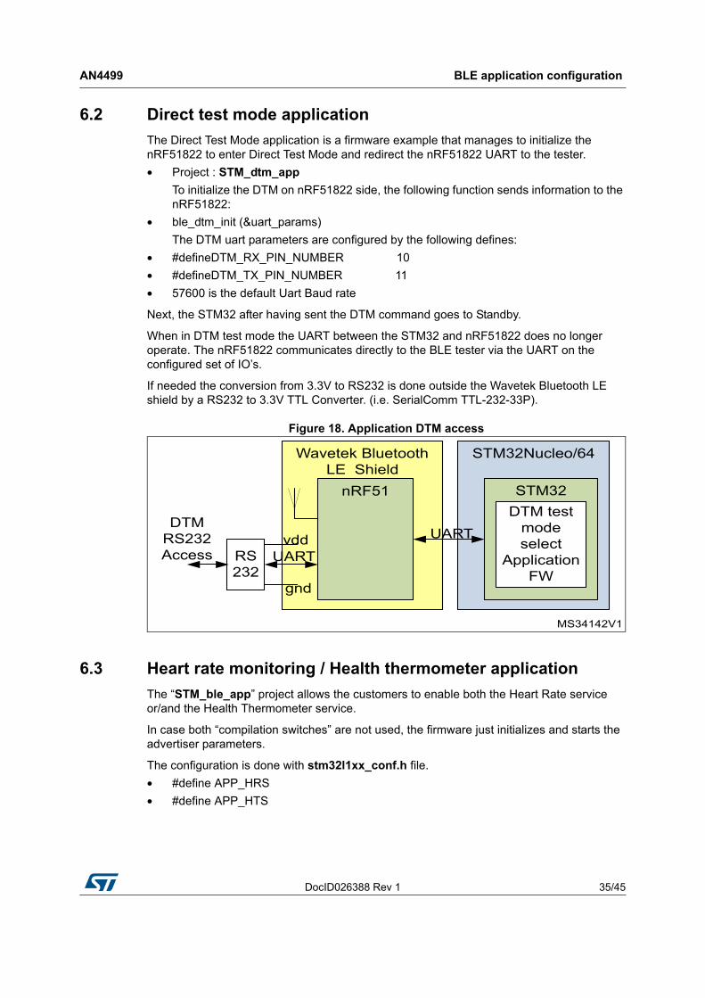
When in DTM test mode the UART between the STM32 and nRF51822 does no longer operate. The nRF51822 communicates directly to the BLE tester via the UART on the configured set of IO’s.
If needed the conversion from 3.3V to RS232 is done outside the Wavetek Bluetooth LE shield by a RS232 to 3.3V TTL Converter. (i.e. SerialComm TTL-232-33P).
Figure 18. Application DTM access
6.3 Heart rate monitoring / Health thermometer application
The “STM_ble_app” project allows the customers to enable both the Heart Rate service or/and the Health Thermometer service.
In case both “compilation switches” are not used, the firmware just initializes and starts the advertiser parameters.
The configuration is done with stm32l1xx_conf.h file.
• #define APP_HRS
• #define APP_HTS
BLE application configuration AN4499
36/45 DocID026388 Rev 1
The application supports the bond manager. The identification information exchanged between central device and peripheral device are store in memory to be used for identity verification when they reconnect in the future.
After the startup of the application, pushing the button “B1” erases all the stored bonding information. It is also recommended to delete the bonding information on the remote device.
Once a BLE connection is done, the button “B1” is used to update and provide the Heart value to the connectivity device.
6.3.1 Advertising application
In case, both “APP_HRS” and “APP_HTS” are not defined, the application manages the advertising interval, the device name, the GAP configuration, and connection establishment according to the following parameters. The application also manages the connection, disconnection and timeout events.
6.3.2 Heart Rate application
Once the “APP_HRS” is defined, the application includes:
• Heart Rate Service
• Device Information Service
• Battery Service
The application reuses the Nordic Services code example.
• ble_hrs.c
• ble_dis.c
• ble_bas.c
The module ble_hrs.c implements the Heart Rate Service with the Heart Rate Measurement, Body Sensor Location and Heart Rate Control Point characteristics. During initialization it adds the Heart Rate Service and Heart Rate Measurement characteristic to the BLE stack database. It also adds the Body Sensor Location and Heart Rate Control Point characteristics.
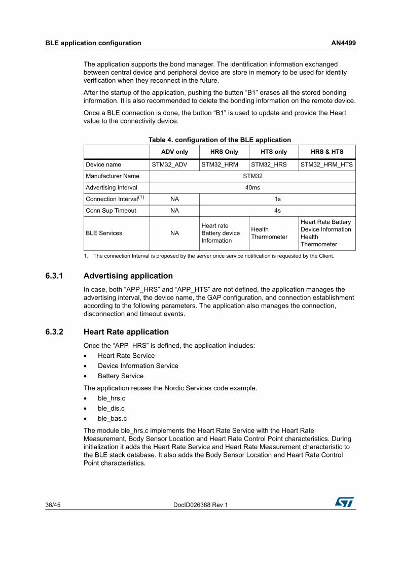
Table 4. configuration of the BLE application
ADV only HRS Only HTS only HRS & HTS
Device name STM32_ADV STM32_HRM STM32_HRS STM32_HRM_HTS
Manufacturer Name STM32
Advertising Interval 40ms
Connection Interval(1)
1. The connection Interval is proposed by the server once service notification is requested by the Client.
NA 1s
Conn Sup Timeout NA 4s
BLE Services NAHeart rate Battery device Information
Health Thermometer
Heart Rate Battery Device Information Health Thermometer
DocID026388 Rev 1 37/45
AN4499 BLE application configuration
43
The module ble_dis.c implements the Device Information Service. During initialization it adds the Device Information Service to the BLE stack database. It then encodes the supplied information, and adds the corresponding characteristics.
The module ble_bas.c implements the Battery Service with the Battery Level characteristic. During initialization it adds the Battery Service and Battery Level characteristic to the BLE stack database. It also adds a Report Reference descriptor to the Battery Level characteristic (used when including the Battery Service in the HID service).
By calling the previous modules, the application initializes the services.
• Initialize Heart Rate Service
– Sensor Location : Finger (can be changed easily by a define)
– Security Level for heart rate service measurement attribute
– Security Level for body sensor location attribute
• Initialize Battery Service
– Security Level for battery characteristics attribute
– Security Level for battery report read attribute
• Initialize Device information Service
– Manufacturer Name : “STM32”
The application manages the GAP configuration, and connection establishment according to the Bluetooth Specification Heart Rate Profile.
The Heart Rate values are provided by an application sensor module (ble_sensorsim.c”), there is no external sensor.
Different timers are started to simulate:
• Battery measurement
• Heart Rate measurement
• RR interval
• Sensor contact detection
At the first connection, the parameters are provided by the client side.
The connection interval is requested by the application once the heart rate notification is enabled by the server. (ble_conn_param.c)
6.3.3 Health thermomether application
Once the “APP_HTS” is defined, the application includes:
• Health Thermomether Service
The application reuses the Nordic Services code example.
• ble_hts.c
The module ble_hts.c implements the Health Thermometer Service to provide to the Client the temperature in Degree Celsius, the Temperature Type and the Time Stamp.
The temperature value is measured by the internal STM32 temperature sensor. There is no external sensor.
At each indication enabled by the remote, the temperature is measured, provided to the nRF51822 and finally transferred to the remote.
The connection parameters are provided by the client side and may be changed by the application.
Performances results AN4499
38/45 DocID026388 Rev 1
7 Performances results
This chapter relates system performance measured for power consumption & data throughput. It describes efficiency of the overall system in term of low power consumption along with maximum data throughput achievable.
7.1 Static power consumption
The referenced STM32 Static power consumption numbers such as Standby mode, Low Power Stop Mode, are to be taken from the STM32 Datasheet reference [6].
7.2 SD command exchange power consumption profile
Next graph shows in detail power values diagram of Power Consumption on STM32 devices for UART message processing through the BLE SD FW MODULE while:
In UART Receiving Mode by Current vs Time using #APP_HRS only:
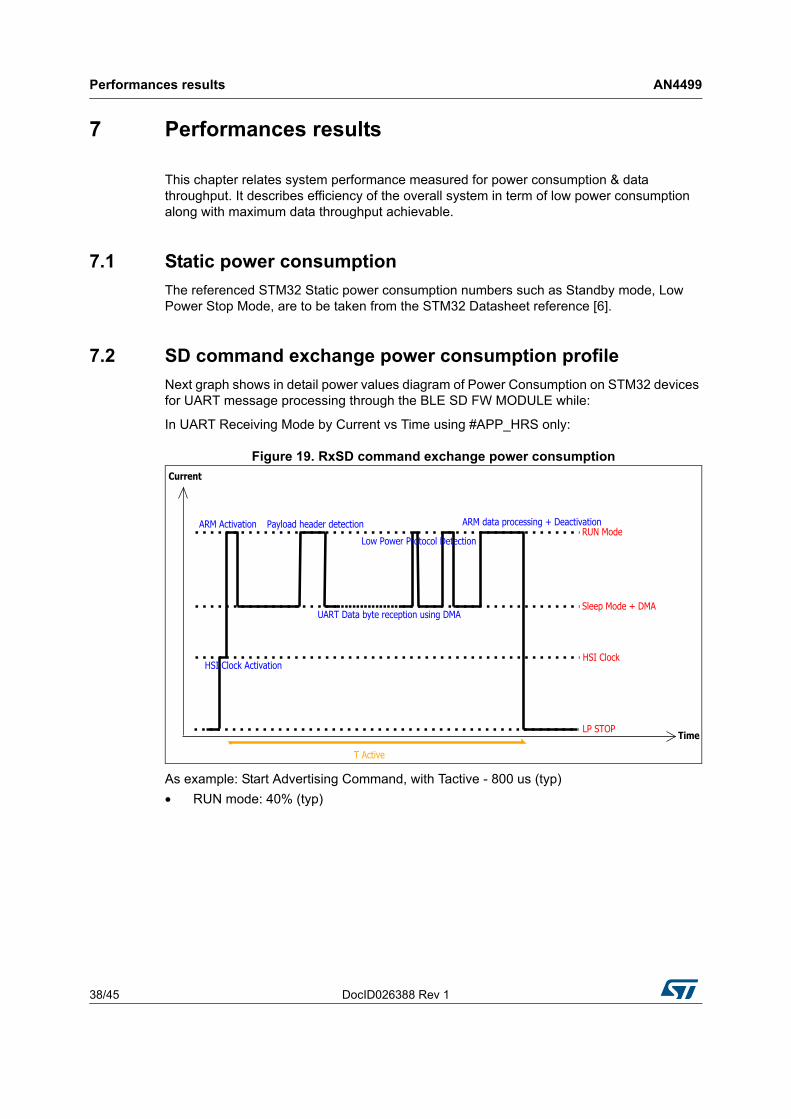
Figure 19. RxSD command exchange power consumption
As example: Start Advertising Command, with Tactive - 800 us (typ)
• RUN mode: 40% (typ)
DocID026388 Rev 1 39/45
AN4499 Performances results
43
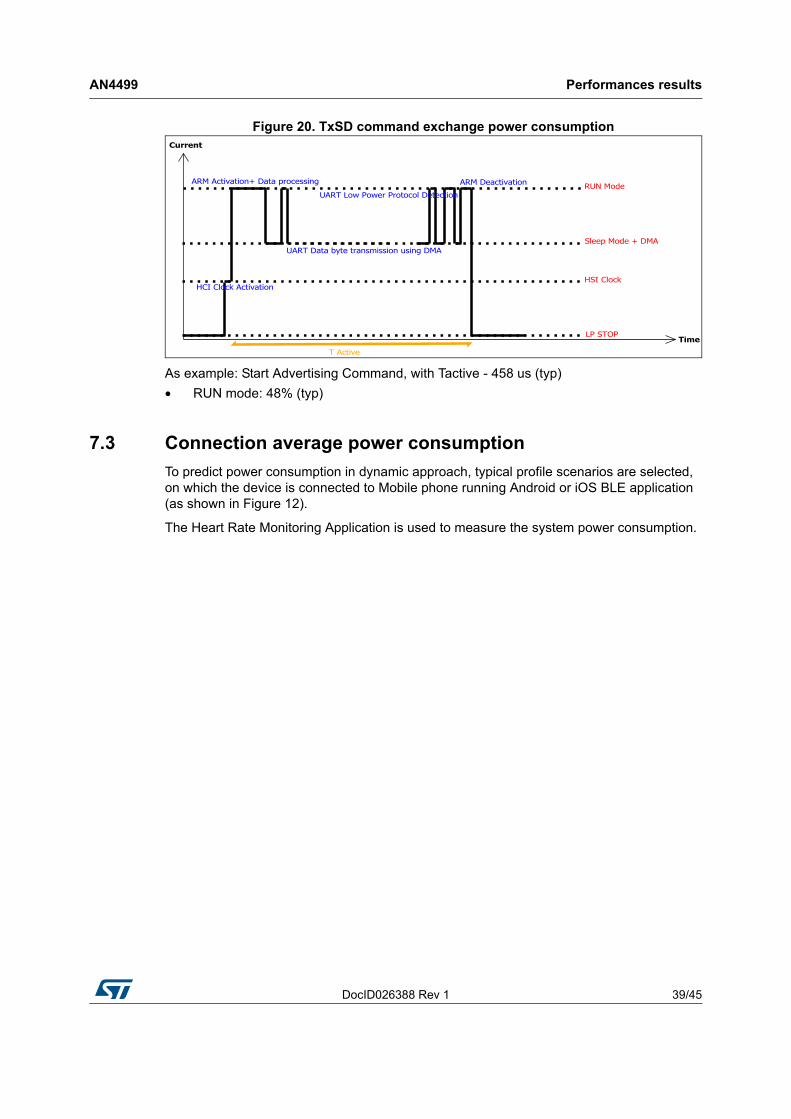
Figure 20. TxSD command exchange power consumption
As example: Start Advertising Command, with Tactive - 458 us (typ)
• RUN mode: 48% (typ)
7.3 Connection average power consumption
To predict power consumption in dynamic approach, typical profile scenarios are selected, on which the device is connected to Mobile phone running Android or iOS BLE application (as shown in Figure 12).
The Heart Rate Monitoring Application is used to measure the system power consumption.
Performances results AN4499
40/45 DocID026388 Rev 1
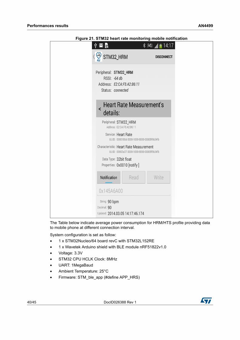
Figure 21. STM32 heart rate monitoring mobile notification
The Table below indicate average power consumption for HRM/HTS profile providing data to mobile phone at different connection interval.
System configuration is set as follow:
• 1 x STM32Nucleo/64 board revC with STM32L152RE
• 1 x Wavetek Arduino shield with BLE module nRF51822v1.0
• Voltage: 3.3V
• STM32 CPU HCLK Clock: 8MHz
• UART: 1MegaBaud
• Ambient Temperature: 25°C
• Firmware: STM_ble_app (#define APP_HRS)
DocID026388 Rev 1 41/45
AN4499 Performances results
43
NB : Numbers are typical, measured on a single STM32 + nRF51822 solution for reference only.
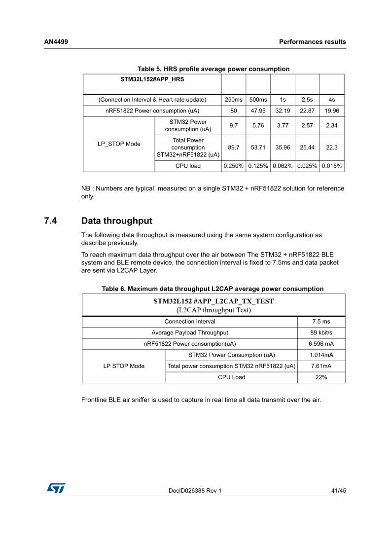
7.4 Data throughput
The following data throughput is measured using the same system configuration as describe previously.
To reach maximum data throughput over the air between The STM32 + nRF51822 BLE system and BLE remote device, the connection interval is fixed to 7.5ms and data packet are sent via L2CAP Layer.
Frontline BLE air sniffer is used to capture in real time all data transmit over the air.
Table 5. HRS profile average power consumption
STM32L152#APP_HRS
(Connection Interval & Heart rate update) 250ms 500ms 1s 2.5s 4s
nRF51822 Power consumption (uA) 80 47.95 32.19 22.87 19.96
LP_STOP Mode
STM32 Power consumption (uA)
9.7 5.76 3.77 2.57 2.34
Total Power consumption
STM32+nRF51822 (uA)89.7 53.71 35.96 25.44 22.3
CPU load 0.250% 0.125% 0.062% 0.025% 0.015%
Table 6. Maximum data throughput L2CAP average power consumption
STM32L152 #APP_L2CAP_TX_TEST(L2CAP throughput Test)
Connection Interval 7.5 ms
Average Payload Throughput 89 kbit/s
nRF51822 Power consumption(uA) 6.596 mA
LP STOP Mode
STM32 Power Consumption (uA) 1.014mA
Total power consumption STM32 nRF51822 (uA) 7.61mA
CPU Load 22%
System limitations AN4499
42/45 DocID026388 Rev 1
8 System limitations
• The STM32 shall not enter standby mode when BLE is enabled.
DocID026388 Rev 1 43/45
AN4499 Revision history
43
9 Revision history
Table 7. Document revision history
Date Revision Changes
25-June-2014 1 initial release
AN4499
44/45 DocID026388 Rev 1
Please Read Carefully:
Information in this document is provided solely in connection with ST products. STMicroelectronics NV and its subsidiaries (“ST”) reserve the right to make changes, corrections, modifications or improvements, to this document, and the products and services described herein at any time, without notice.
All ST products are sold pursuant to ST’s terms and conditions of sale.
Purchasers are solely responsible for the choice, selection and use of the ST products and services described herein, and ST assumes no liability whatsoever relating to the choice, selection or use of the ST products and services described herein.
No license, express or implied, by estoppel or otherwise, to any intellectual property rights is granted under this document. If any part of this document refers to any third party products or services it shall not be deemed a license grant by ST for the use of such third party products or services, or any intellectual property contained therein or considered as a warranty covering the use in any manner whatsoever of such third party products or services or any intellectual property contained therein.
UNLESS OTHERWISE SET FORTH IN ST’S TERMS AND CONDITIONS OF SALE ST DISCLAIMS ANY EXPRESS OR IMPLIED WARRANTY WITH RESPECT TO THE USE AND/OR SALE OF ST PRODUCTS INCLUDING WITHOUT LIMITATION IMPLIED WARRANTIES OF MERCHANTABILITY, FITNESS FOR A PARTICULAR PURPOSE (AND THEIR EQUIVALENTS UNDER THE LAWS OF ANY JURISDICTION), OR INFRINGEMENT OF ANY PATENT, COPYRIGHT OR OTHER INTELLECTUAL PROPERTY RIGHT.
ST PRODUCTS ARE NOT DESIGNED OR AUTHORIZED FOR USE IN: (A) SAFETY CRITICAL APPLICATIONS SUCH AS LIFE SUPPORTING, ACTIVE IMPLANTED DEVICES OR SYSTEMS WITH PRODUCT FUNCTIONAL SAFETY REQUIREMENTS; (B) AERONAUTIC APPLICATIONS; (C) AUTOMOTIVE APPLICATIONS OR ENVIRONMENTS, AND/OR (D) AEROSPACE APPLICATIONS OR ENVIRONMENTS. WHERE ST PRODUCTS ARE NOT DESIGNED FOR SUCH USE, THE PURCHASER SHALL USE PRODUCTS AT PURCHASER’S SOLE RISK, EVEN IF ST HAS BEEN INFORMED IN WRITING OF SUCH USAGE, UNLESS A PRODUCT IS EXPRESSLY DESIGNATED BY ST AS BEING INTENDED FOR “AUTOMOTIVE, AUTOMOTIVE SAFETY OR MEDICAL” INDUSTRY DOMAINS ACCORDING TO ST PRODUCT DESIGN SPECIFICATIONS. PRODUCTS FORMALLY ESCC, QML OR JAN QUALIFIED ARE DEEMED SUITABLE FOR USE IN AEROSPACE BY THE CORRESPONDING GOVERNMENTAL AGENCY.
Resale of ST products with provisions different from the statements and/or technical features set forth in this document shall immediately void any warranty granted by ST for the ST product or service described herein and shall not create or extend in any manner whatsoever, any liability of ST.
ST and the ST logo are trademarks or registered trademarks of ST in various countries.Information in this document supersedes and replaces all information previously supplied.
The ST logo is a registered trademark of STMicroelectronics. All other names are the property of their respective owners.
© 2014 STMicroelectronics - All rights reserved
STMicroelectronics group of companies
Australia - Belgium - Brazil - Canada - China - Czech Republic - Finland - France - Germany - Hong Kong - India - Israel - Italy - Japan - Malaysia - Malta - Morocco - Philippines - Singapore - Spain - Sweden - Switzerland - United Kingdom - United States of America
www.st.com