Embed Size (px)
Citation preview
Structural Use of Fibre-Reinforced Polymer
(FRP) Composites in Construction: Past Achievements and Future Opportunities
Jin-Guang Teng 滕锦光
Chair Professor of Structural Engineering &
Director of Research Institute for Sustainable Urban Development (RISUD)
The Hong Kong Polytechnic University (PolyU)
香港理工大学
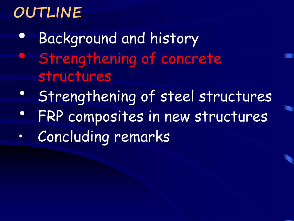
OUTLINE
• Background and history
• Strengthening of concrete structures
• Strengthening of steel structures
• FRP composites in new structures
• Concluding remarks
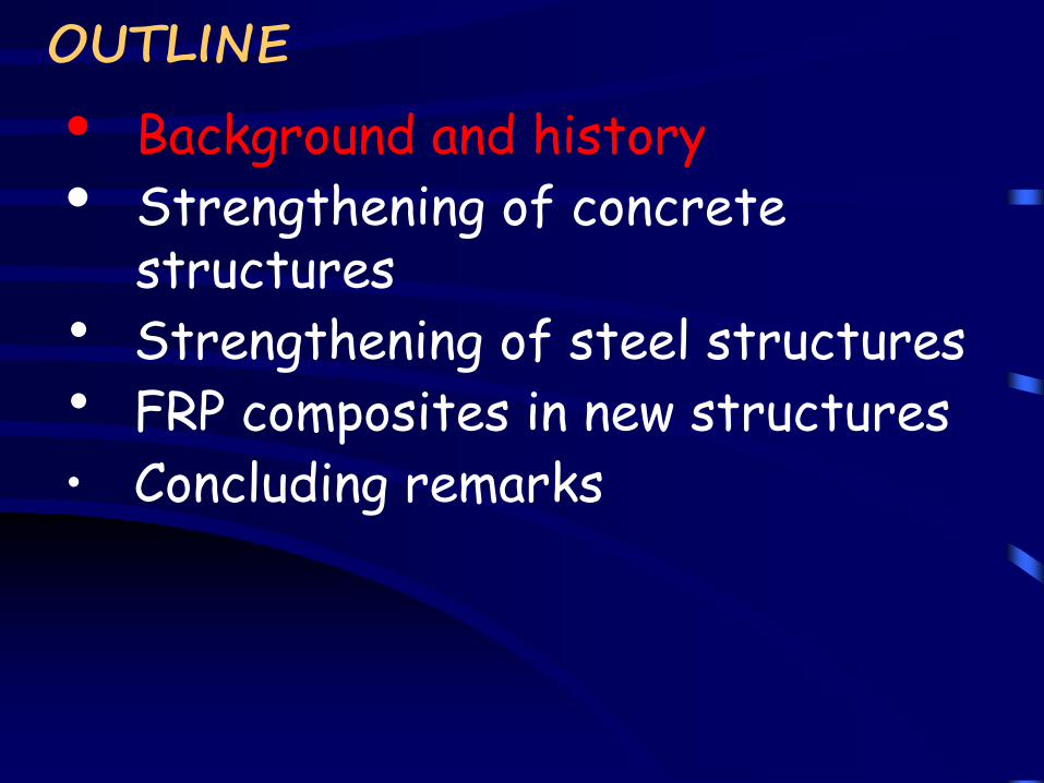
Span = 14 meters
By Amoorland
The First Reinforced Concrete Bridge Chazelet Bridge in France, by Joseph Monier, 1875
The first reinforced concrete building (a small two-story servant's cottage) was erected in 1854 by a plasterer, William B. Wilkinson of Newcastle-upon-Tyne, UK.
In 1824, Joseph Aspdin, from Leeds, England, patented the Portland cement; it resembled a natural stone quarried on the nearby Isle of Portland.
https://en.wikipedia.org
Corrosion in Concrete Structures
http://www.adbengineering.com/services/structural-inspections/
http://is2c.nl/project-10979/files/Corrosion_to_Rebar_of_Concrete_Pile.jpg
Fibre-Reinforced Polymer (FRP) Composites
Fibers
Resin matrix
Fiber-reinforced polymer (FRP) composites are formed by embedding continuous fibres in a polymeric resin matrix
0.0 0.5 1.0 1.5 2.0 2.5 3.00
500
1000
1500
2000
2500
3000
Mild steel
GFRP
Str
ess
(MP
a)
Strain (%)
CFRP
AFRP = Aramid FRP
BFRP = Basalt FRP
CFRP = Carbon FRP
GFRP = Glass FRP
FRP Products for Strengthening Applications
Why FRP Composites?
ADVANTAGES:
Have all the advantages of steel plates for plate bonding
Speedy application; Minimal increases in structural
weight and size.
High strength/weight ratio
Lifting equipment eliminated; Reduced labour cost.
Flexibility in shape
Can be handled in rolls; easy for wrapping on curved
surfaces and around columns.
Tailorability of material properties
Providing mechanical resistance in chosen directions
through appropriate fibre orientations and lamination
structures
High resistance to corrosion and other chemical attacks
Durable performance.
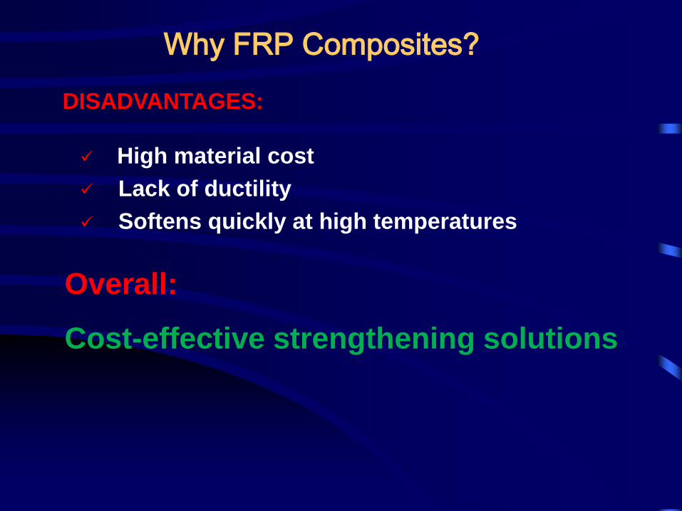
DISADVANTAGES:
High material cost
Lack of ductility
Softens quickly at high temperatures
Overall:
Cost-effective strengthening solutions
Why FRP Composites?
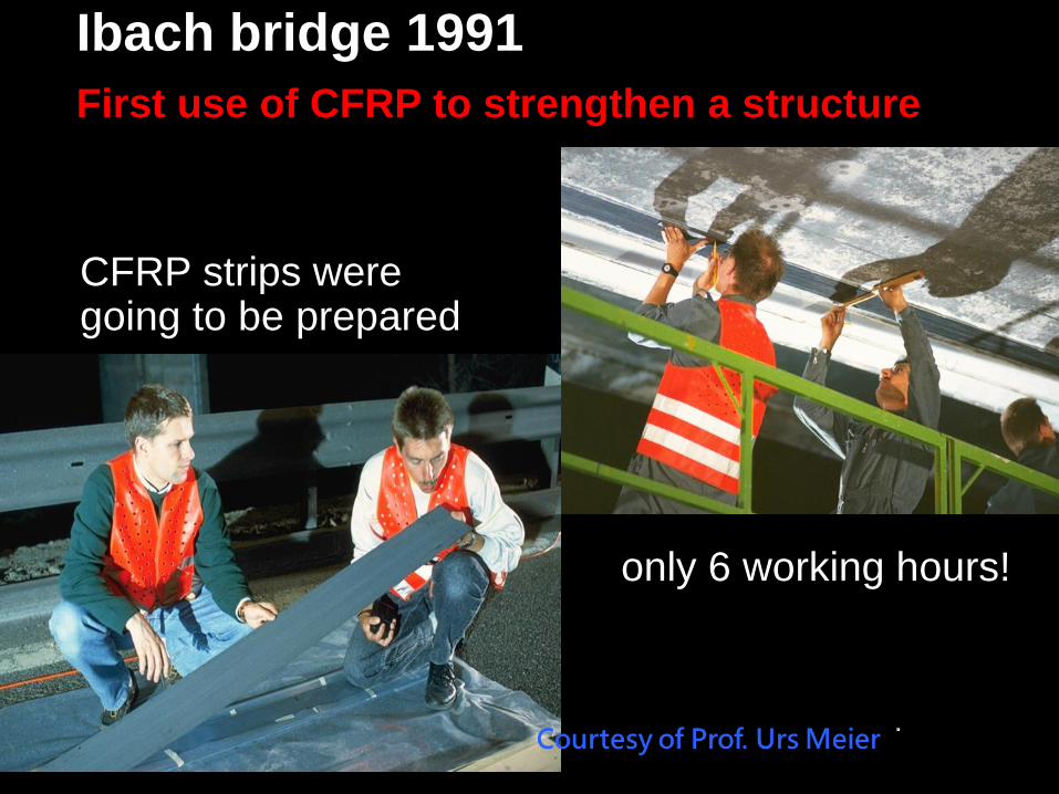
Ibach bridge 1991
only 6 working hours!
CFRP strips were going to be prepared
Ibach bridge 1991
First use of CFRP to strengthen a structure
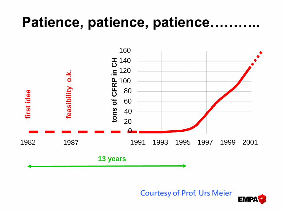
13 years
0
20
40
60
80
100
120
140
160
1991 1993 1995 1997 1999 20011982 1987
firs
t id
ea
feasib
ilit
y
o.k
.
ton
s o
f C
FR
P i
n C
H
Patience, patience, patience………..
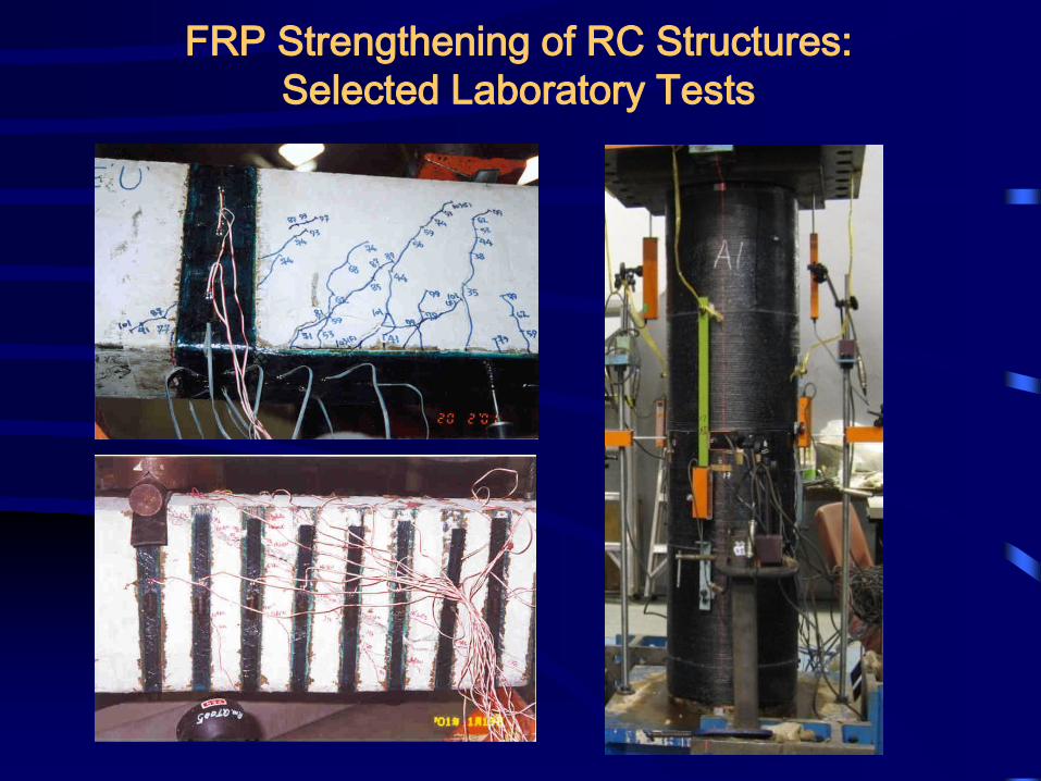
FRP Strengthening of RC Structures:
Selected Laboratory Tests
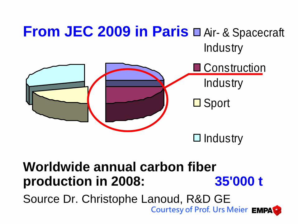
From JEC 2009 in Paris
Worldwide annual carbon fiber production in 2008: 35'000 t
Source Dr. Christophe Lanoud, R&D GE
Air- & Spacecraft
Industry
Construction
Industry
Sport
Industry
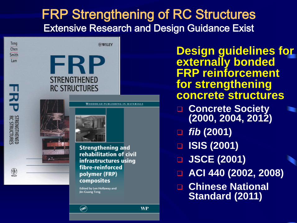
FRP Strengthening of RC StructuresExtensive Research and Design Guidance Exist
Concrete Society (2000, 2004, 2012)
fib (2001)
ISIS (2001)
JSCE (2001)
ACI 440 (2002, 2008)
Chinese National Standard (2011)
Design guidelines for externally bonded FRP reinforcement for strengthening concrete structures
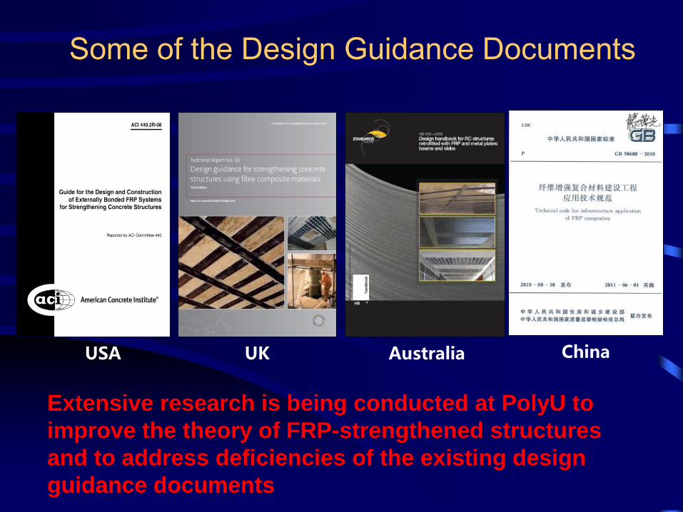
Some of the Design Guidance Documents
USA UK Australia China
Extensive research is being conducted at PolyU to
improve the theory of FRP-strengthened structures
and to address deficiencies of the existing design
guidance documents
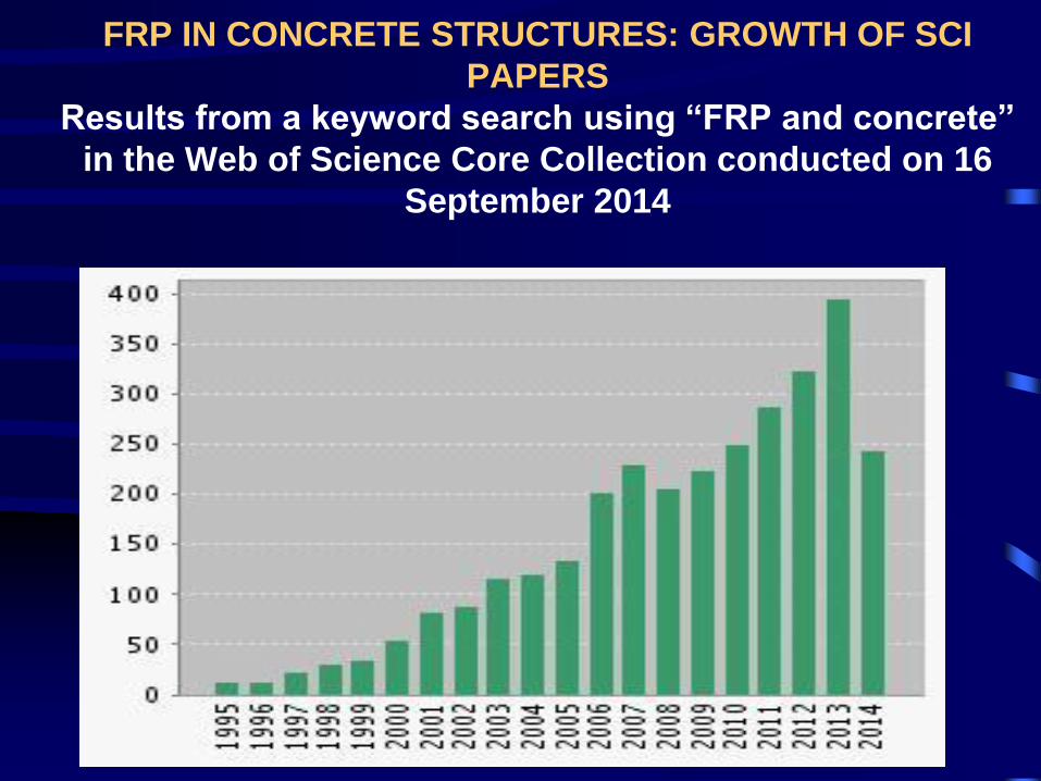
FRP IN CONCRETE STRUCTURES: GROWTH OF SCI
PAPERS
Results from a keyword search using “FRP and concrete”
in the Web of Science Core Collection conducted on 16
September 2014
OUTLINE
• Background and history
• Strengthening of concrete structures
• Strengthening of steel structures
• FRP composites in new structures
• Concluding remarks

Flexural Strengthening of Concrete Beams
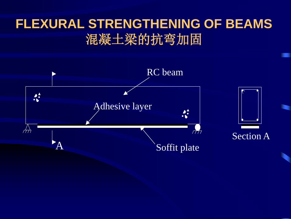
FLEXURAL STRENGTHENING OF BEAMS
混凝土梁的抗弯加固
RC beam
Soffit plate
Adhesive layer
ASection A
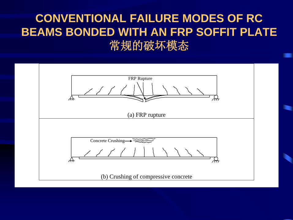
CONVENTIONAL FAILURE MODES OF RC
BEAMS BONDED WITH AN FRP SOFFIT PLATE
常规的破坏模态
(a) FRP rupture
(b) Crushing of compressive concrete
Concrete Crushing
FRP Rupture
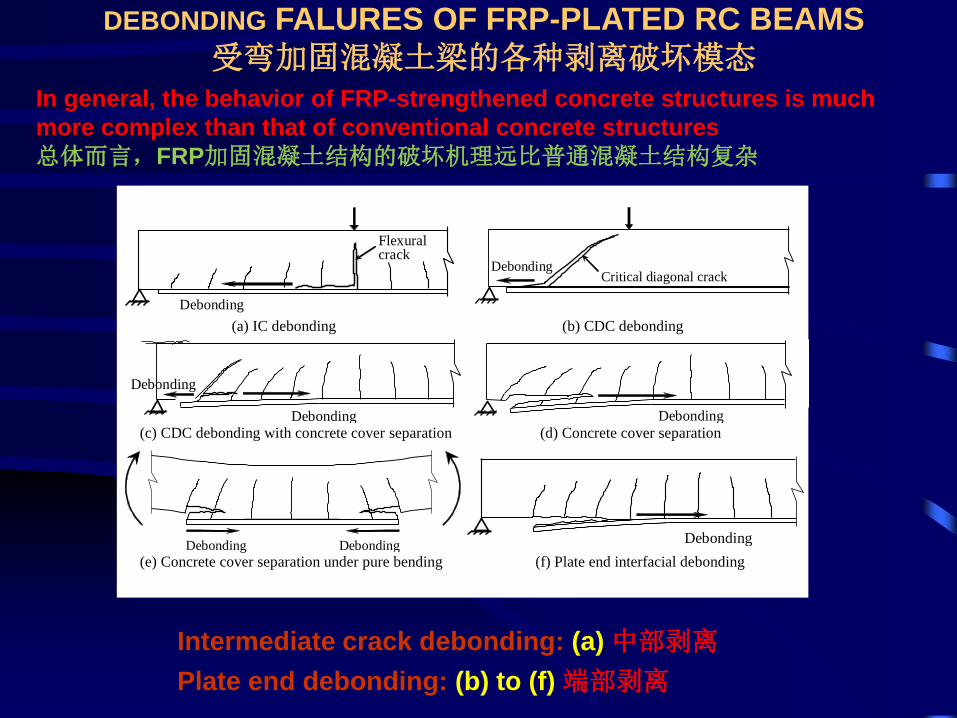
DEBONDING FALURES OF FRP-PLATED RC BEAMS
受弯加固混凝土梁的各种剥离破坏模态In general, the behavior of FRP-strengthened concrete structures is much
more complex than that of conventional concrete structures
总体而言,FRP加固混凝土结构的破坏机理远比普通混凝土结构复杂
Debonding
Flexural crack
Debonding Critical diagonal crack
(a) IC debonding (b) CDC debonding
Debonding
Debonding
Debonding (c) CDC debonding with concrete cover separation (d) Concrete cover separation
Debonding Debonding
Debonding
(e) Concrete cover separation under pure bending (f) Plate end interfacial debonding
Intermediate crack debonding: (a) 中部剥离
Plate end debonding: (b) to (f) 端部剥离
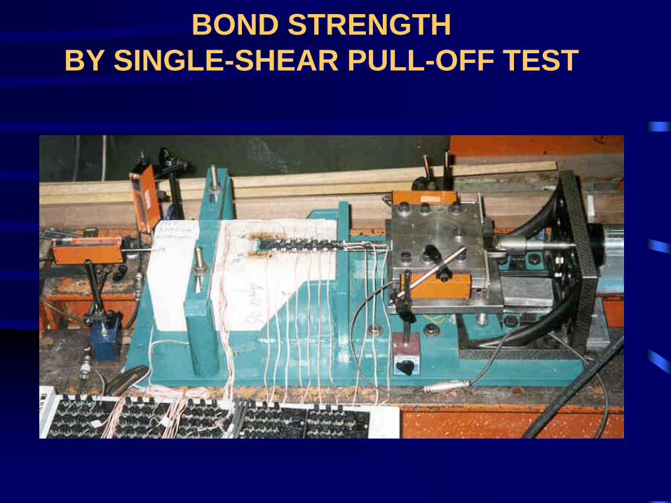
BOND STRENGTH
BY SINGLE-SHEAR PULL-OFF TEST
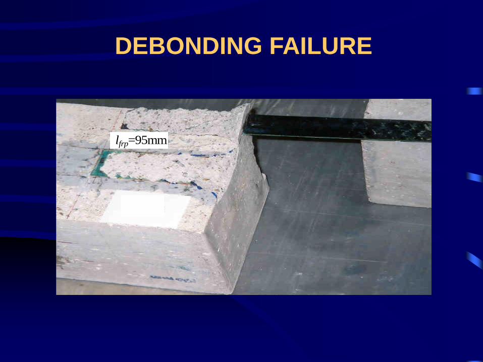
lfrp=95mm
DEBONDING FAILURE

BEHAVIOUR OF BONDED JOINTS
Failure generally occurs in the concrete adjacent to the
adhesive-to-concrete bi-material interface
An increase of the bond length L may not increase the
bond strength.
Tensile rupture of the FRP plate generally does not
occur in such a test
Bonded plateConcrete
P
L
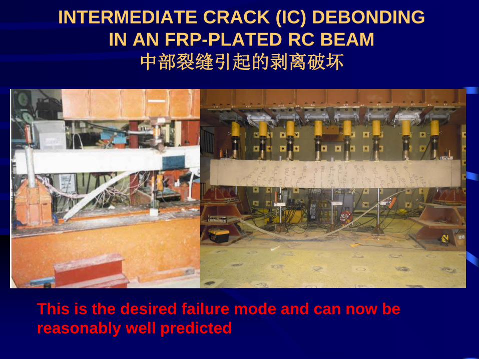
INTERMEDIATE CRACK (IC) DEBONDING
IN AN FRP-PLATED RC BEAM
中部裂缝引起的剥离破坏
This is the desired failure mode and can now be
reasonably well predicted
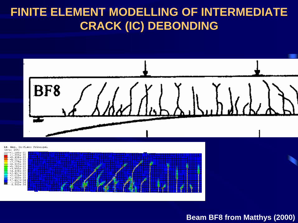
FINITE ELEMENT MODELLING OF INTERMEDIATE
CRACK (IC) DEBONDING
Beam BF8 from Matthys (2000)
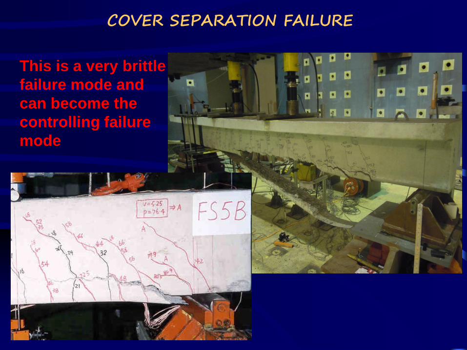
COVER SEPARATION FAILURE
This is a very brittle
failure mode and
can become the
controlling failure
mode
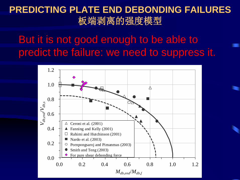
PREDICTING PLATE END DEBONDING FAILURES
板端剥离的强度模型
0.0
0.2
0.4
0.6
0.8
1.0
1.2
0.0 0.2 0.4 0.6 0.8 1.0 1.2
Vd
b,e
nd/V
db
,s
Mdb,end/Mdb,f
Ceroni et al. (2001)
Fanning and Kelly (2001)
Rahimi and Hutchinson (2001)
Nardo et al. (2003)
Pornpongsaroj and Pimanmas (2003)
Smith and Teng (2003)
For pure shear debonding force
But it is not good enough to be able to
predict the failure: we need to suppress it.
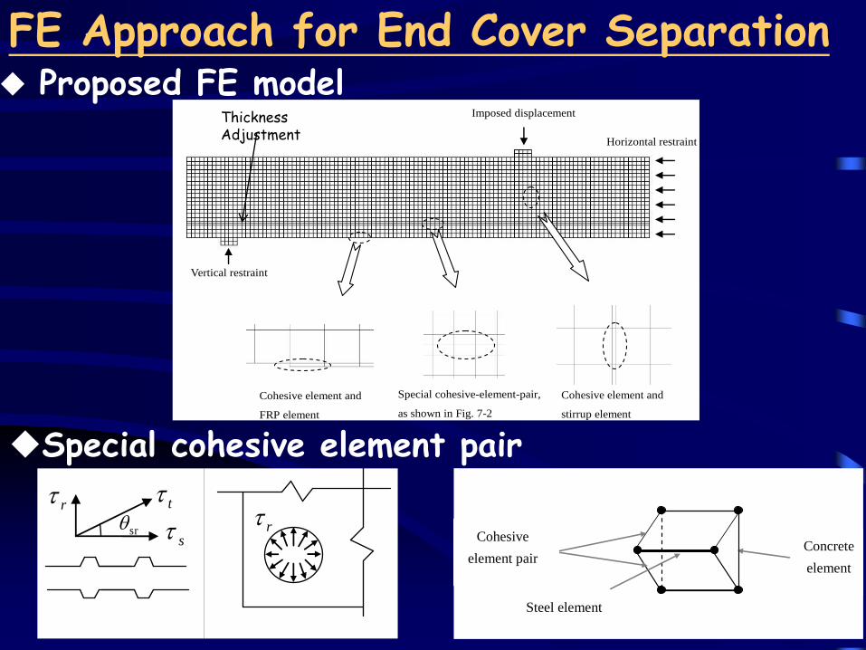
FE Approach for End Cover Separation
Imposed displacement
Vertical restraint
Horizontal restraint
Special cohesive-element-pair,
as shown in Fig. 7-2
Cohesive element and
FRP element
Cohesive element and
stirrup element
Thickness Adjustment
Proposed FE model
Cohesive
element pair
Steel element
Concrete
element
Special cohesive element pair
rs
r t
sr
rs
r t
sr
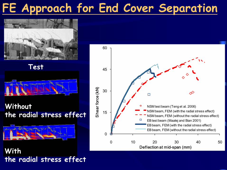
FE Approach for End Cover Separation
0
15
30
45
60
0 10 20 30 40 50
Sh
ea
r fo
rce (
kN
)
Def lection at mid-span (mm)
NSM test beam (Teng et al. 2006)
NSM beam, FEM (with the radial stress effect)
NSM beam, FEM (without the radial stress effect)
EB test beam (Maalej and Bian 2001)
EB beam, FEM (with the radial stress effect)
EB beam, FEM (without the radial stress effect)
Test
Without the radial stress effect
With the radial stress effect
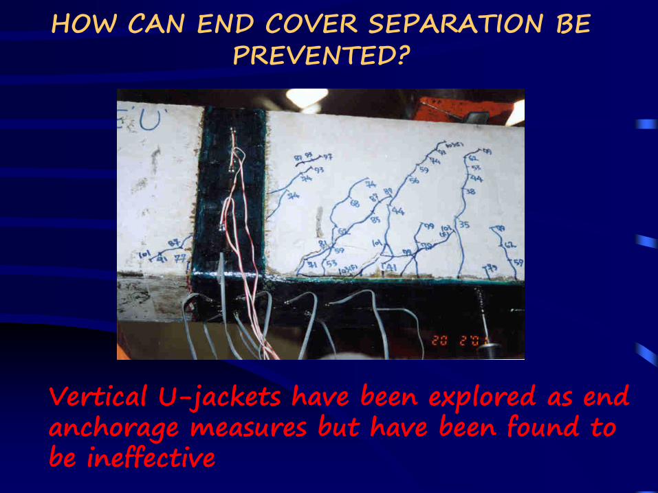
HOW CAN END COVER SEPARATION BE PREVENTED?
Vertical U-jackets have been explored as end anchorage measures but have been found to be ineffective
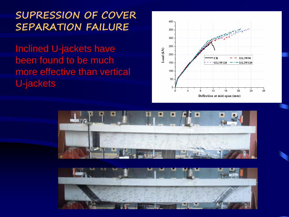
SUPRESSION OF COVER SEPARATION FAILURE
Inclined U-jackets have
been found to be much
more effective than vertical
U-jackets

Shear Strengthening of Concrete Beams
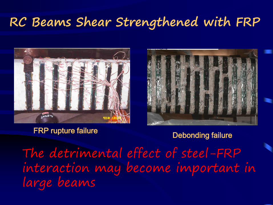
RC Beams Shear Strengthened with FRP
The detrimental effect of steel-FRP interaction may become important in large beams
FRP rupture failureDebonding failure
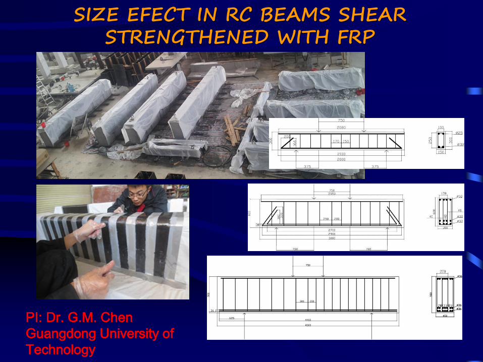
SIZE EFECT IN RC BEAMS SHEAR STRENGTHENED WITH FRP
PI: Dr. G.M. Chen
Guangdong University of
Technology
SIZE EFECT IN RC BEAMS SHEAR STRENGTHENED WITH FRP
PI: Dr. G.M. Chen, Guangdong University of Technology

Axial Strengthening of Concrete Columns
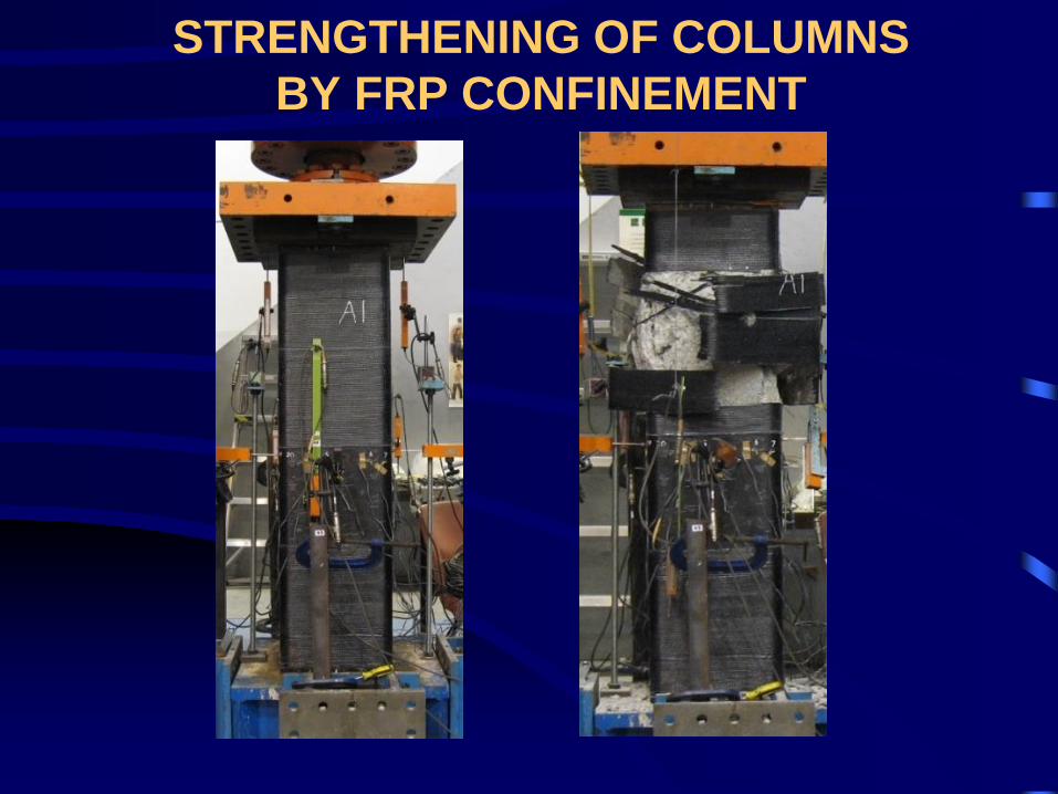
STRENGTHENING OF COLUMNS
BY FRP CONFINEMENT
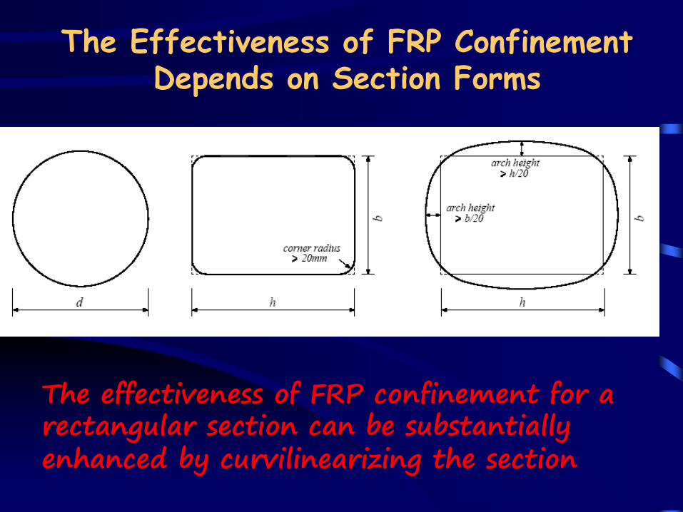
The Effectiveness of FRP Confinement Depends on Section Forms
The effectiveness of FRP confinement for a rectangular section can be substantially enhanced by curvilinearizing the section
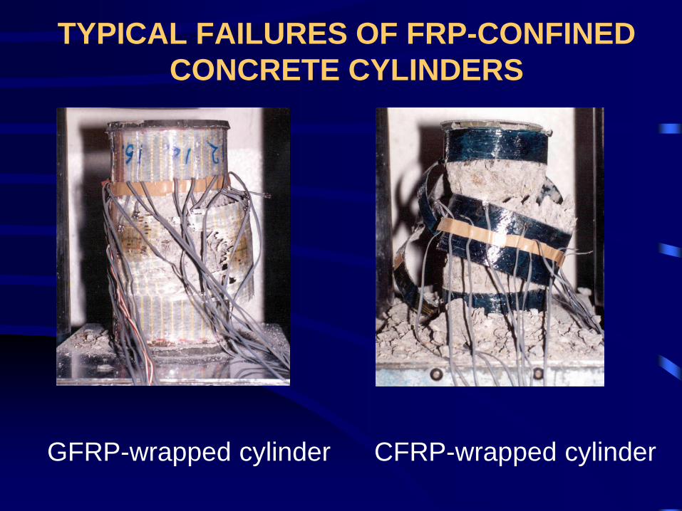
TYPICAL FAILURES OF FRP-CONFINED
CONCRETE CYLINDERS
GFRP-wrapped cylinder CFRP-wrapped cylinder
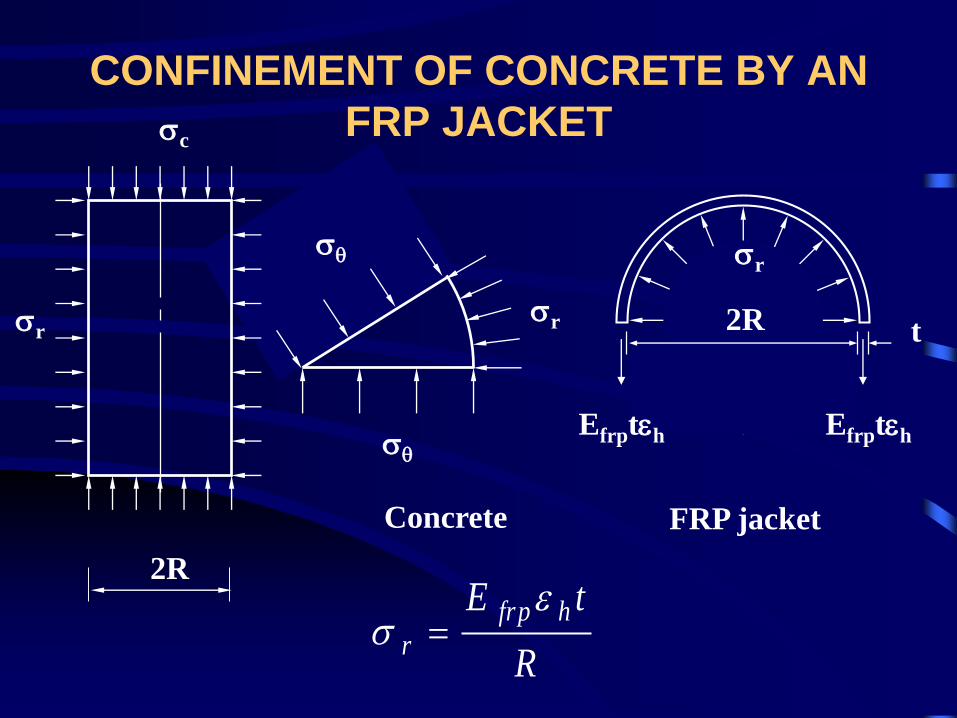
s
s
sr 2R
sr
t
Efrpteh Efrpteh
Concrete FRP jacket
2R
sc
sr
CONFINEMENT OF CONCRETE BY AN
FRP JACKET
R
tE hfrp
r
es
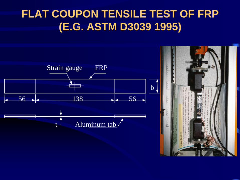
FLAT COUPON TENSILE TEST OF FRP
(E.G. ASTM D3039 1995)
b
56 138 56
FRP
t Aluminum tab
Strain gauge
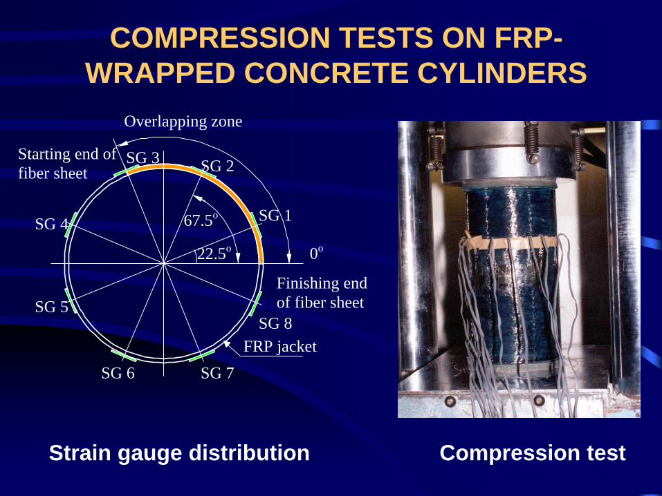
COMPRESSION TESTS ON FRP-
WRAPPED CONCRETE CYLINDERS
Strain gauge distribution Compression test
22.5o
67.5o
Finishing end
of fiber sheet
Starting end of
fiber sheet
Overlapping zone
FRP jacket
0o
SG 1
SG 2SG 3
SG 4
SG 5
SG 6 SG 7
SG 8
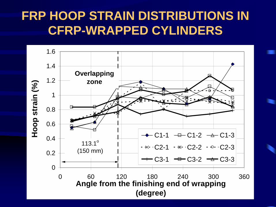
FRP HOOP STRAIN DISTRIBUTIONS IN
CFRP-WRAPPED CYLINDERS
0
0.2
0.4
0.6
0.8
1
1.2
1.4
1.6
0 60 120 180 240 300 360Angle from the finishing end of wrapping
(degree)
Ho
op
str
ain
(%
)
C1-1 C1-2 C1-3
C2-1 C2-2 C2-3
C3-1 C3-2 C3-3
Overlapping
zone
113.1o
(150 mm)
A RELIABLE AND UNIFIED
MODEL FOR FRP-CONFINED
CONCRETE SHOULD BE
BASED ON ACTUAL HOOP
RUPTURE STRAINS
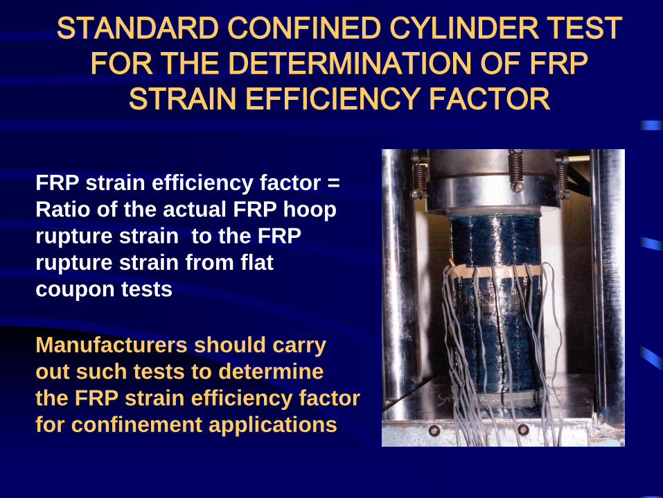
STANDARD CONFINED CYLINDER TEST
FOR THE DETERMINATION OF FRP
STRAIN EFFICIENCY FACTOR
FRP strain efficiency factor =
Ratio of the actual FRP hoop
rupture strain to the FRP
rupture strain from flat
coupon tests
Manufacturers should carry
out such tests to determine
the FRP strain efficiency factor
for confinement applications
DIFFERENT TYPES OF STRESS-STRAIN CURVES
ecu
Axial strain ec
'
cof
'
ccf
Axia
l str
ess s
c
ecu
'
cof
'
ccf
Axia
l str
ess s
c
'
cuf
ecc
Axial strain ec ecu
'
cof
'
ccf
Axia
l str
ess s
c '
cuf
ecc
1'' cocu ff
21 '' c oc u ff
2'' cocu ff
weakly-confined
moderately-confined
heavily-confined
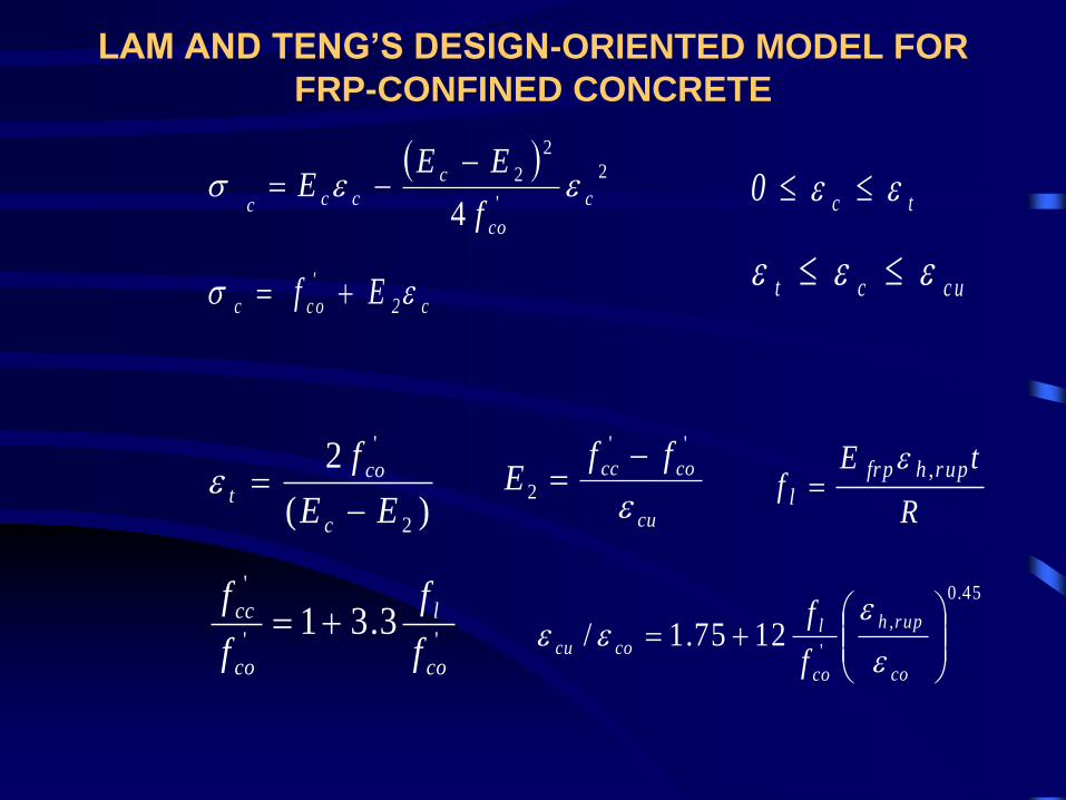
LAM AND TENG’S DESIGN-ORIENTED MODEL FOR
FRP-CONFINED CONCRETE
2
'
2
2
4c
co
c
ccc f
EEE ees
tc0 ee
c2
'
c oc Ef es c uct eee
)(
2
2
'
EE
f
c
co
t
ecu
cocc ffE
e
''
2
45.0
,
'1275.1/
co
ruph
co
lcocu
f
f
e
eee''
'
3.31co
l
co
cc
f
f
f
f
R
tEf
ruphfrp
l
,e
LAM AND TENG’S STRESS-STRAIN MODEL
Axial Strain, ec
Axia
l S
tre
ss,
sc
Unconfined Concrete
(GB 50010)
FRP-confined Concete
(Lam and Teng)
fcc
fco
eco
et 0.0033 e
cu
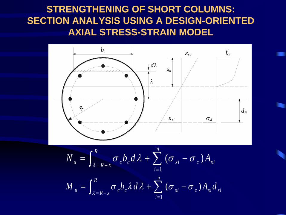
STRENGTHENING OF SHORT COLUMNS:
SECTION ANALYSIS USING A DESIGN-ORIENTED
AXIAL STRESS-STRAIN MODEL
xn
R
si
bc
d
cu
sid
'ccf
si
1
( )nR
u c c si c siR x
i
N b d A
s s s
1
( )nR
u c c si c si siR x
i
M b d A d
s s s
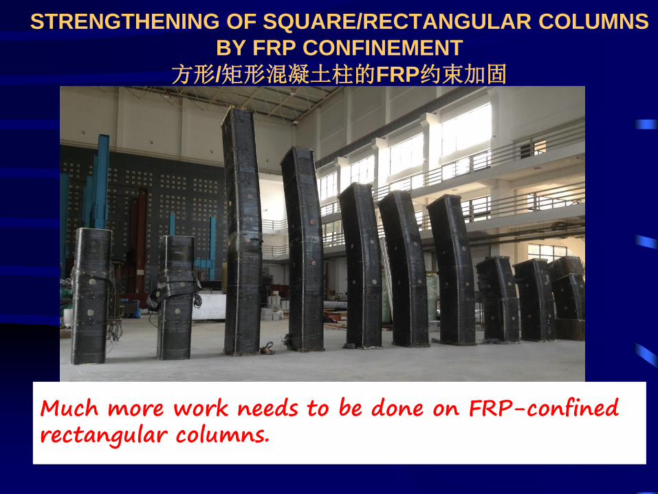
STRENGTHENING OF SQUARE/RECTANGULAR COLUMNS
BY FRP CONFINEMENT
方形/矩形混凝土柱的FRP约束加固
Much more work needs to be done on FRP-confined rectangular columns.
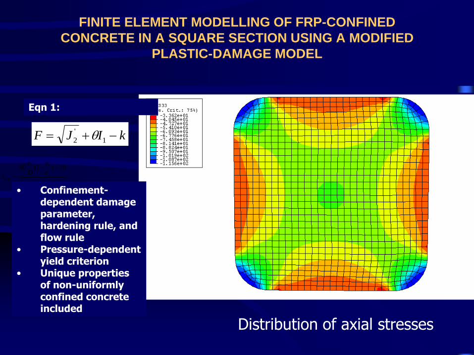
FINITE ELEMENT MODELLING OF FRP-CONFINED
CONCRETE IN A SQUARE SECTION USING A MODIFIED
PLASTIC-DAMAGE MODEL
2 1
2
',
'
60 (1 ) 20
(1 0.06 )
crit
h rupcc
coco
e e
D e
f
f
e
e
Distribution of axial stresses
• Confinement-dependent damage parameter, hardening rule, and flow rule
• Pressure-dependent yield criterion
• Unique properties of non-uniformly confined concrete included
kIJF 1
'
2
Eqn 1:
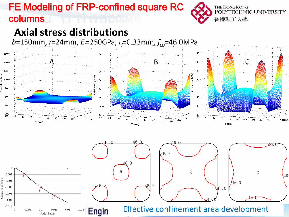
FE Modeling of FRP-confined square RC
columns
52
Axial stress distributions
A B C
b=150mm, r=24mm, Ej=250GPa, tj=0.33mm, fco=46.0MPa
46.0
46.0
46.0
46.0
46.0
46.0
46.0
46.0
46.0
46.0
46.0
46.0
46.0
A B C
0
10
20
30
40
50
60
70
0 0.005 0.01 0.015 0.02 0.025
Ax
ial
Str
ess
(MP
a)
Axial Strain
A
BC
-0.012
-0.01
-0.008
-0.006
-0.004
-0.002
0
0 0.005 0.01 0.015 0.02 0.025
Co
rner
ho
op
str
ain
Axial Strain
A
B
C
Effective confinement area development
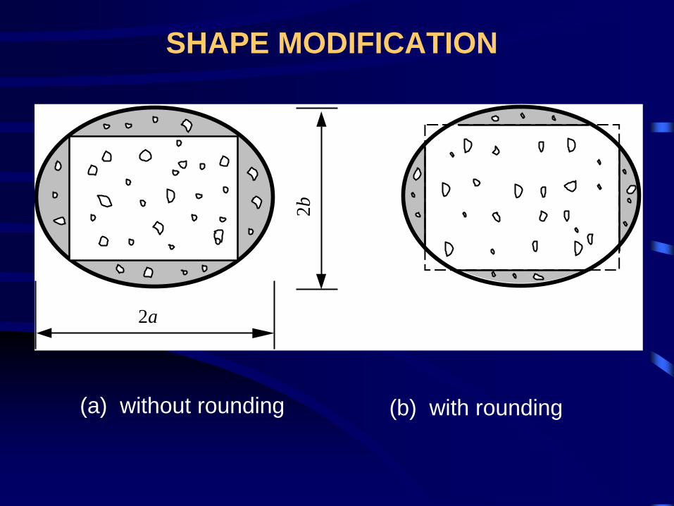
SHAPE MODIFICATION
2a2
b
(a) without rounding (b) with rounding
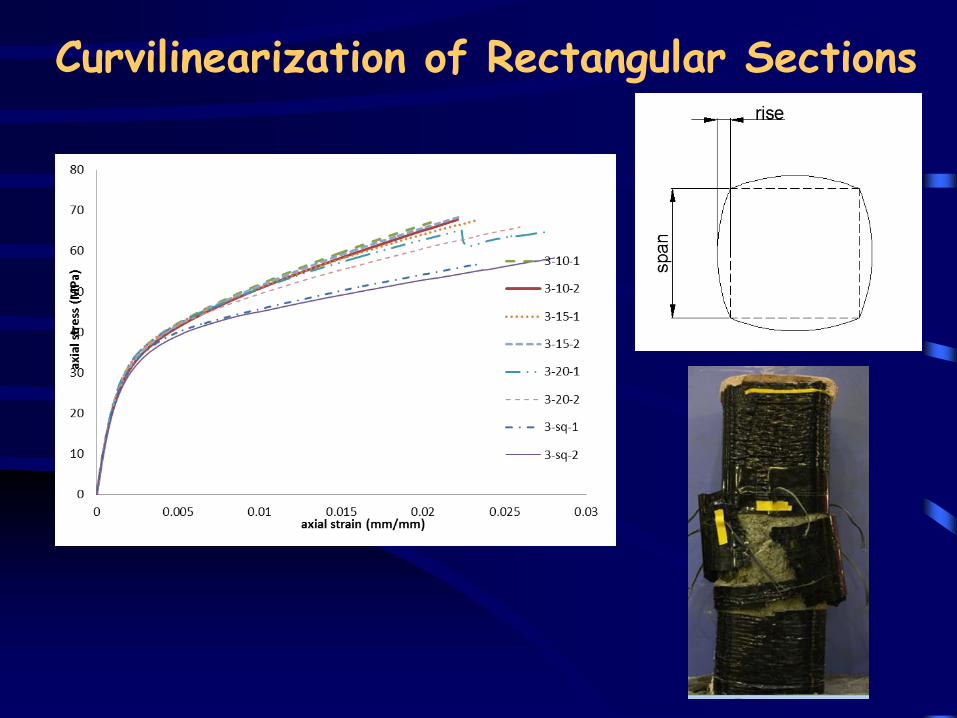
Curvilinearization of Rectangular Sections

Seismic Retrofit of Concrete Columns
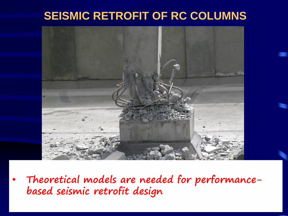
SEISMIC RETROFIT OF RC COLUMNS
• Theoretical models are needed for performance-based seismic retrofit design
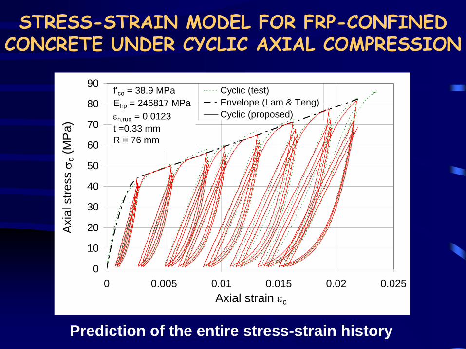
STRESS-STRAIN MODEL FOR FRP-CONFINED CONCRETE UNDER CYCLIC AXIAL COMPRESSION
Prediction of the entire stress-strain history
0
10
20
30
40
50
60
70
80
90
0 0.005 0.01 0.015 0.02 0.025
Axial strain ec
Axia
l str
ess s
c (
MP
a)
Cyclic (test)
Envelope (Lam & Teng)
Cyclic (proposed)
f'co = 38.9 MPa
Efrp = 246817 MPa
eh,rup = 0.0123
t =0.33 mm
R = 76 mm
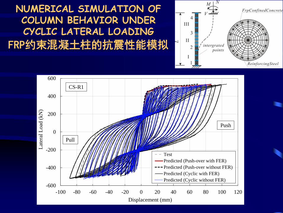
NUMERICAL SIMULATION OF COLUMN BEHAVIOR UNDER CYCLIC LATERAL LOADING
FRP约束混凝土柱的抗震性能模拟
-600
-400
-200
0
200
400
600
-100 -80 -60 -40 -20 0 20 40 60 80 100 120
Lat
eral
Load
(kN
)
Displacement (mm)
Test
Predicted (Push-over with FER)
Predicted (Push-over without FER)
Predicted (Cyclic with FER)
Predicted (Cyclic without FER)
Push
Pull
CS-R1
Strengthening of Concrete Structures with Near-Surface Mounted FRP Reinforcement
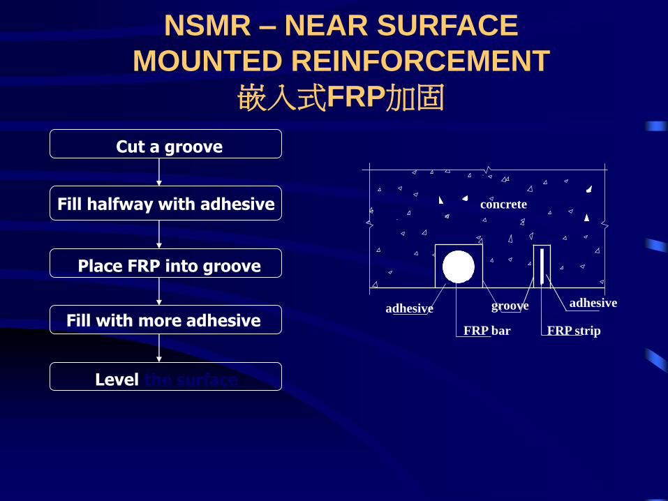
NSMR – NEAR SURFACE
MOUNTED REINFORCEMENT
嵌入式FRP加固
Cut a groove
Fill halfway with adhesive
Place FRP into groove
Fill with more adhesive
Level the surface
concrete
groove
FRP bar
adhesive
FRP strip
adhesive
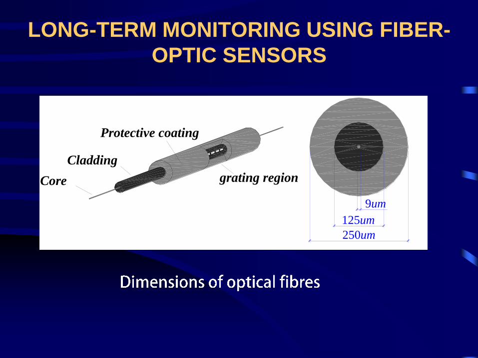
LONG-TERM MONITORING USING FIBER-
OPTIC SENSORS
grating region
Cladding
Protective coating
9um
125um
250um
Core
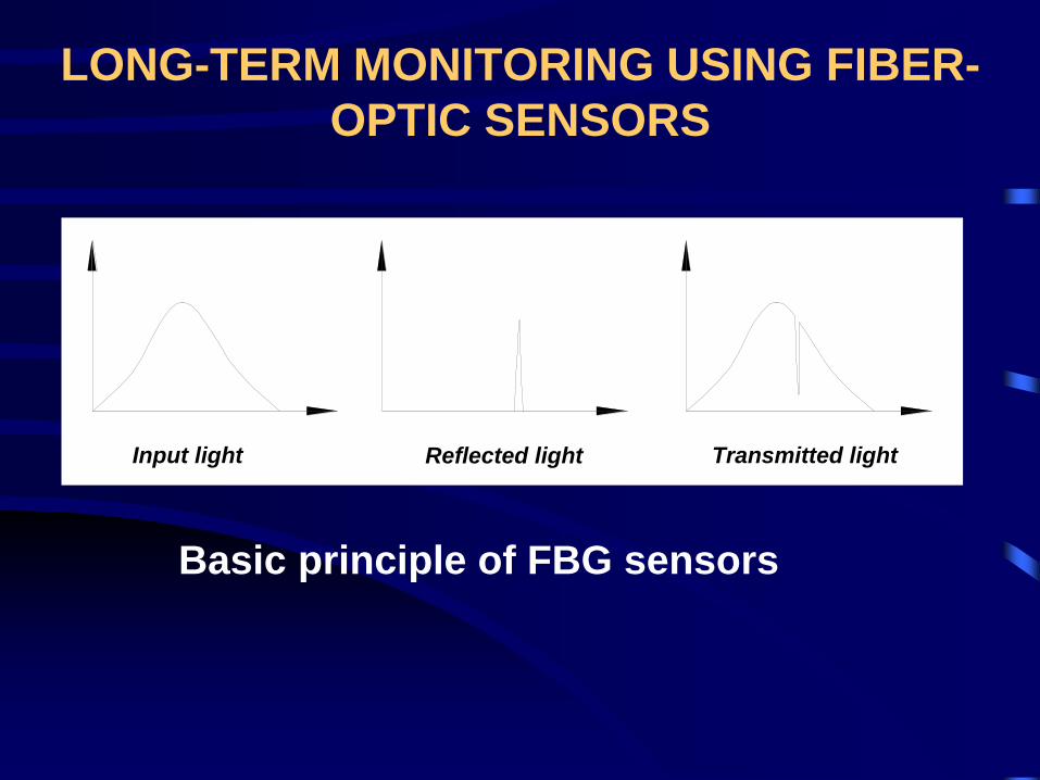
LONG-TERM MONITORING USING FIBER-
OPTIC SENSORS
Input light Reflected light Transmitted light
Basic principle of FBG sensors
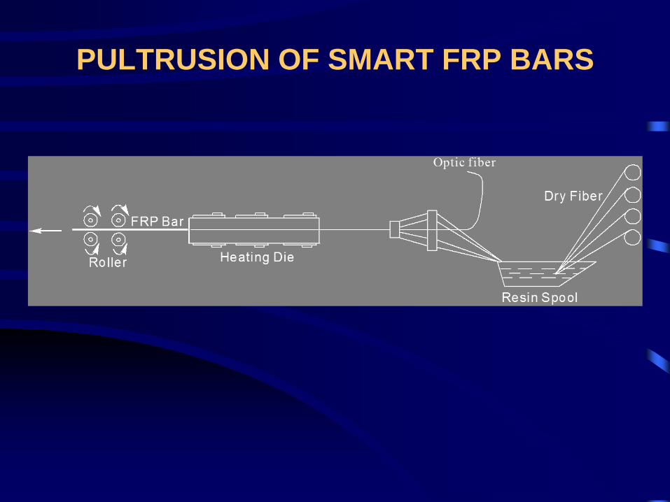
PULTRUSION OF SMART FRP BARS
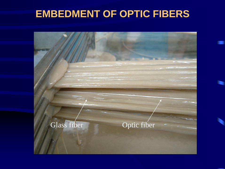
Optic fiberGlass fiber
EMBEDMENT OF OPTIC FIBERS
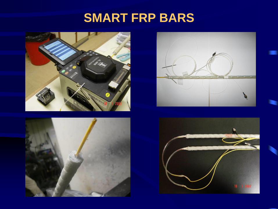
SMART FRP BARS
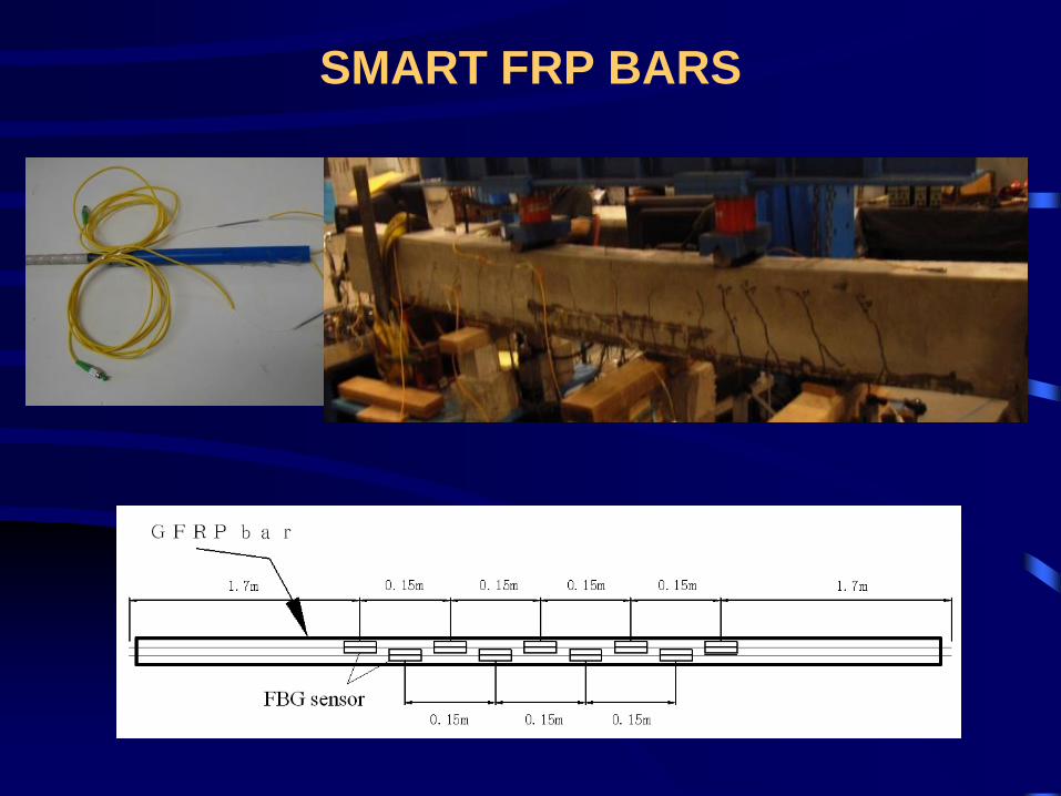
SMART FRP BARS
OUTLINE
• Background and history
• Strengthening of concrete structures
• Strengthening of steel structures
• FRP composites in new structures
• Concluding remarks
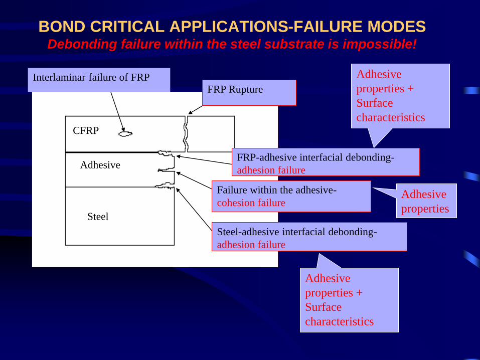
BOND CRITICAL APPLICATIONS-FAILURE MODESDebonding failure within the steel substrate is impossible!
Steel
Adhesive
CFRP
Interlaminar failure of FRPFRP Rupture
FRP-adhesive interfacial debonding-
adhesion failure
Failure within the adhesive-
cohesion failure
Steel-adhesive interfacial debonding-
adhesion failure
Adhesive
properties +
Surface
characteristics
Adhesive
properties
Adhesive
properties +
Surface
characteristics
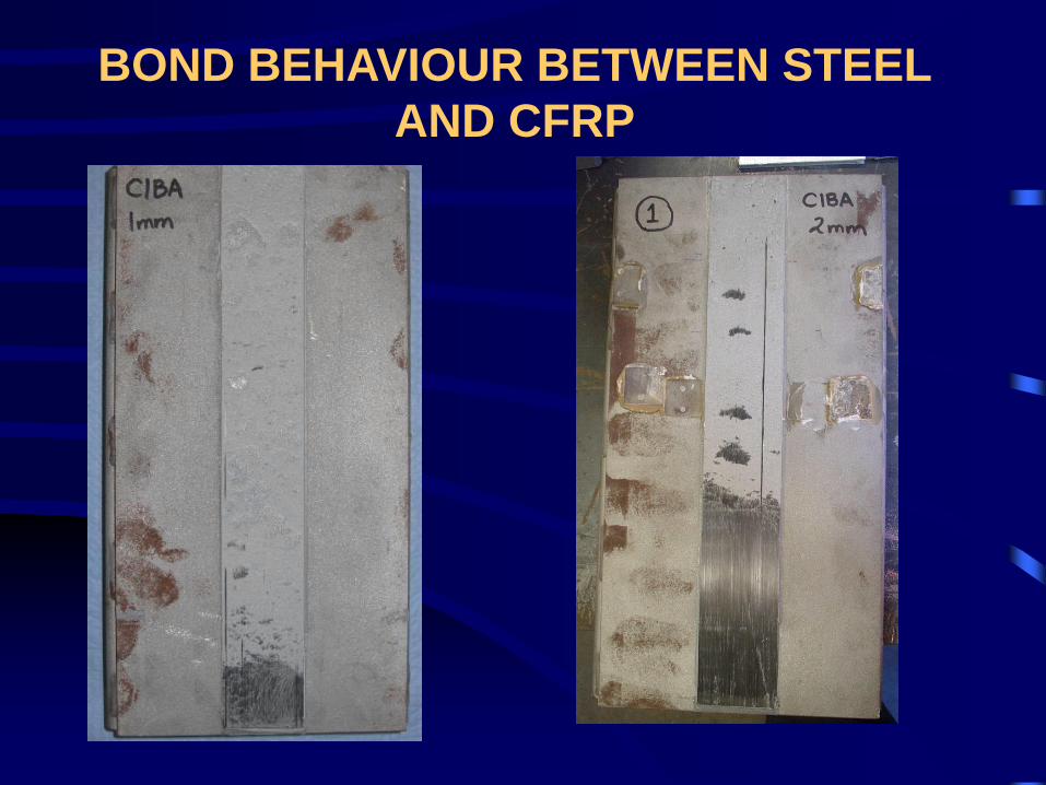
BOND BEHAVIOUR BETWEEN STEEL
AND CFRP
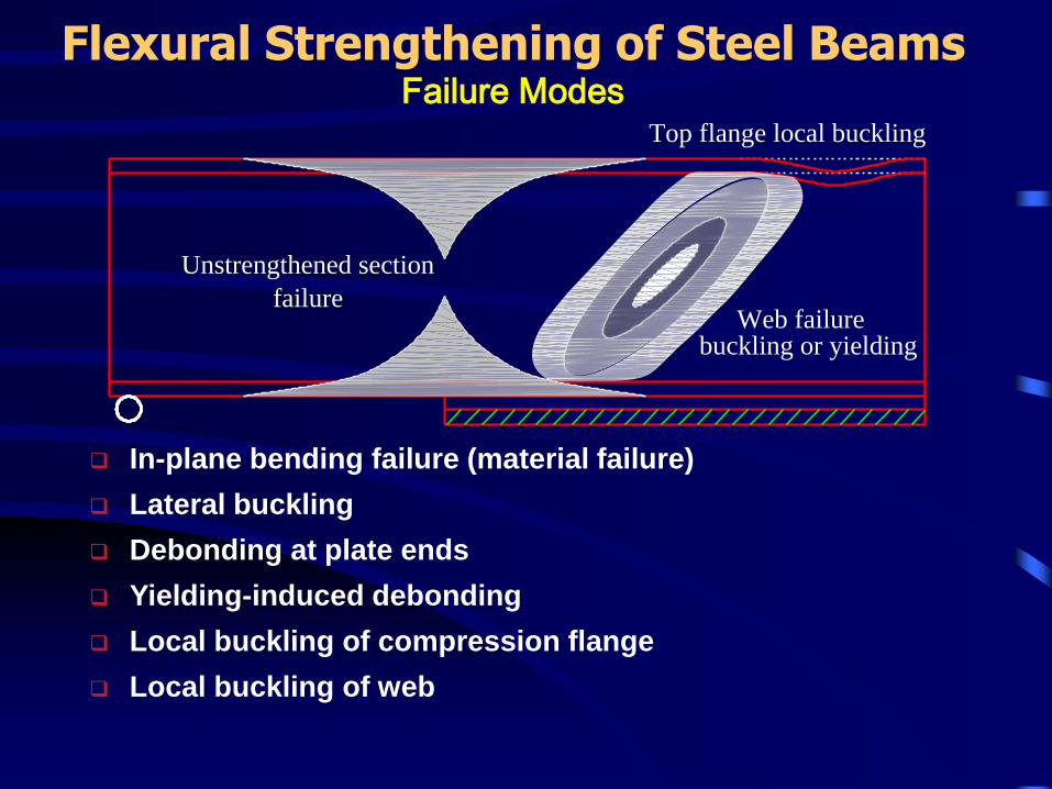
In-plane bending failure (material failure)
Lateral buckling
Debonding at plate ends
Yielding-induced debonding
Local buckling of compression flange
Local buckling of web
Flexural Strengthening of Steel BeamsFailure Modes
Top flange local buckling
Unstrengthened section
Web failurefailure
buckling or yielding
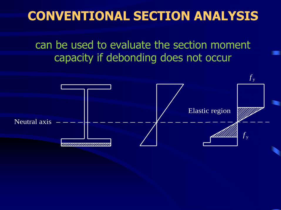
CONVENTIONAL SECTION ANALYSIS
can be used to evaluate the section moment capacity if debonding does not occur
Neutral axis
f y
Elastic region
f y
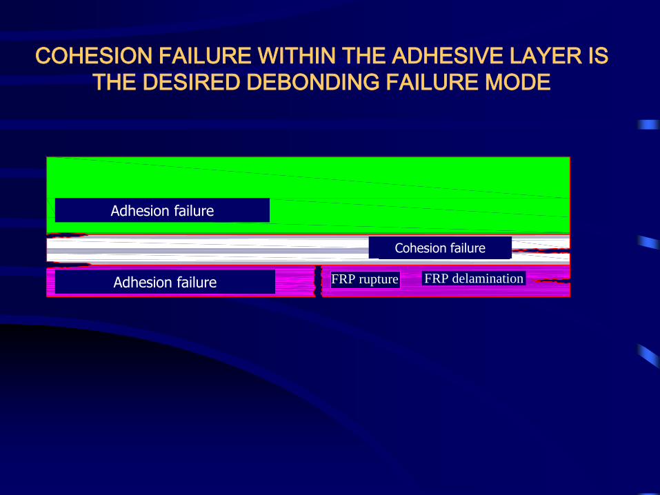
FRP/adhesive interface debonding FRP rupture FRP delamination
Adhesive layer failure
Adhesive/steel interface debonding
COHESION FAILURE WITHIN THE ADHESIVE LAYER IS
THE DESIRED DEBONDING FAILURE MODE
Cohesion failure
Adhesion failure
Adhesion failure
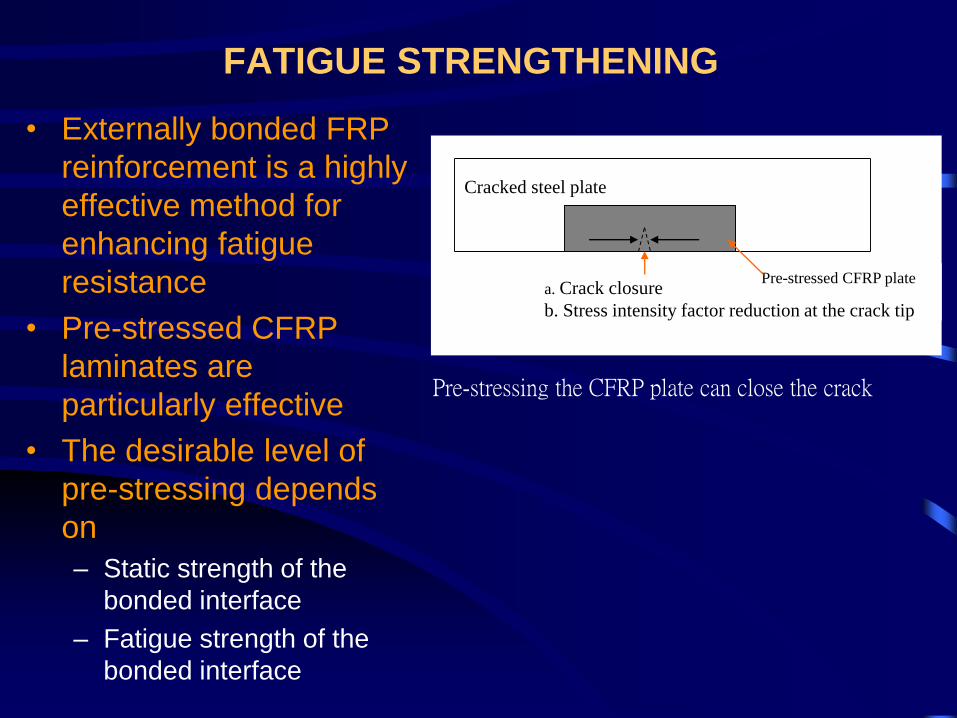
FATIGUE STRENGTHENING
• Externally bonded FRP
reinforcement is a highly
effective method for
enhancing fatigue
resistance
• Pre-stressed CFRP
laminates are
particularly effective
• The desirable level of
pre-stressing depends
on
– Static strength of the
bonded interface
– Fatigue strength of the
bonded interface
Pre-stressed CFRP platea. Crack closure
b. Stress intensity factor reduction at the crack tip
Cracked steel plate
Pre-stressing the CFRP plate can close the crack
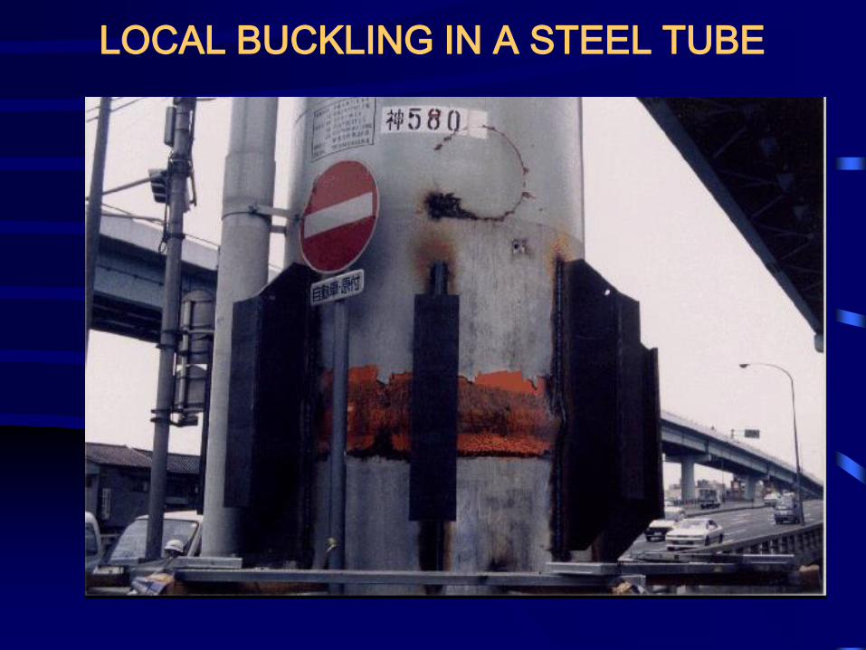
LOCAL BUCKLING IN A STEEL TUBE
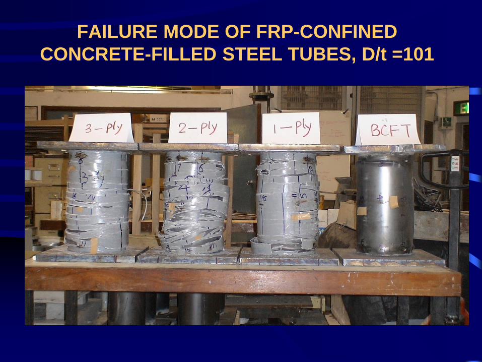
FAILURE MODE OF FRP-CONFINED
CONCRETE-FILLED STEEL TUBES, D/t =101
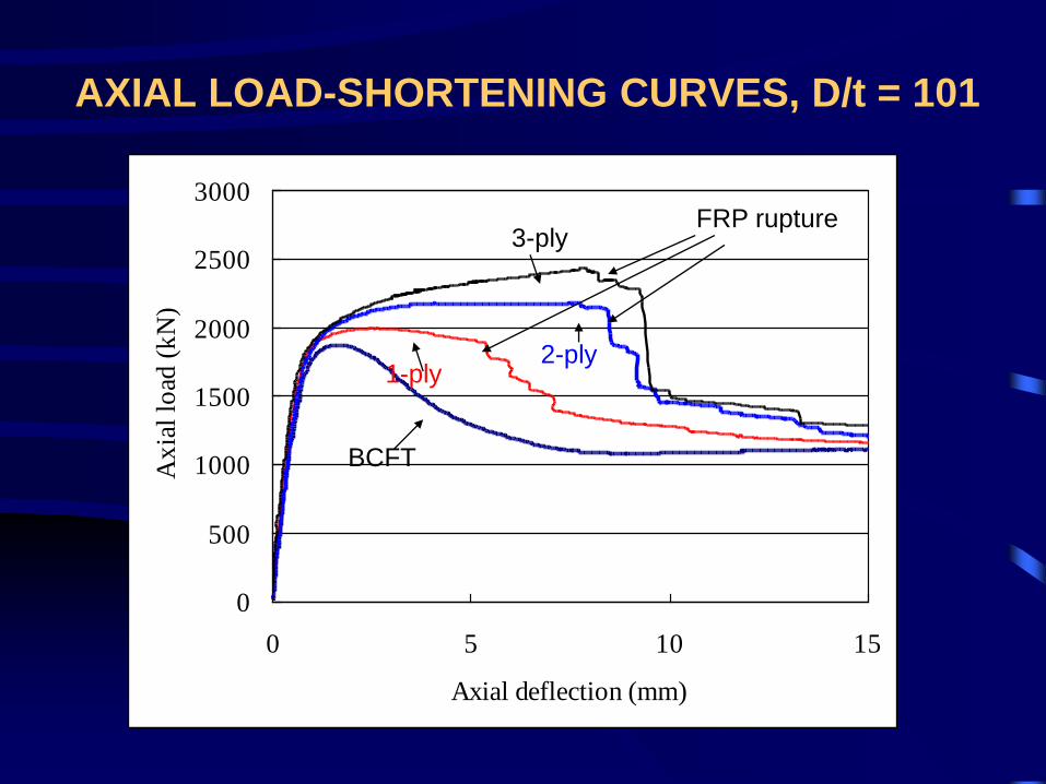
AXIAL LOAD-SHORTENING CURVES, D/t = 101
BCFT
3-ply
0
500
1000
1500
2000
2500
3000
0 5 10 15
Axial deflection (mm)
Ax
ial
load
(k
N)
BCFT
1-ply2-ply
3-plyFRP rupture
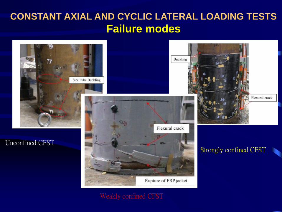
CONSTANT AXIAL AND CYCLIC LATERAL LOADING TESTS
Failure modes
Unconfined CFST
Weakly confined CFST
Strongly confined CFST
OUTLINE
• Background and history
• Strengthening of concrete structures
• Strengthening of steel structures
• FRP composites in new structures
• Concluding remarks
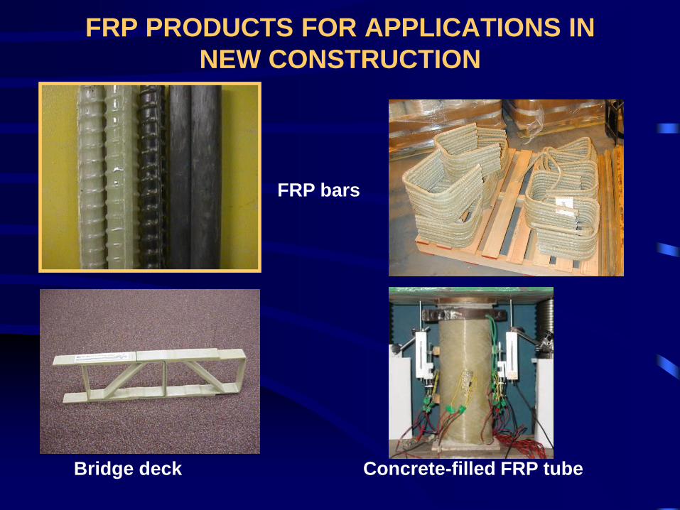
FRP bars
Bridge deck Concrete-filled FRP tube
FRP PRODUCTS FOR APPLICATIONS IN
NEW CONSTRUCTION
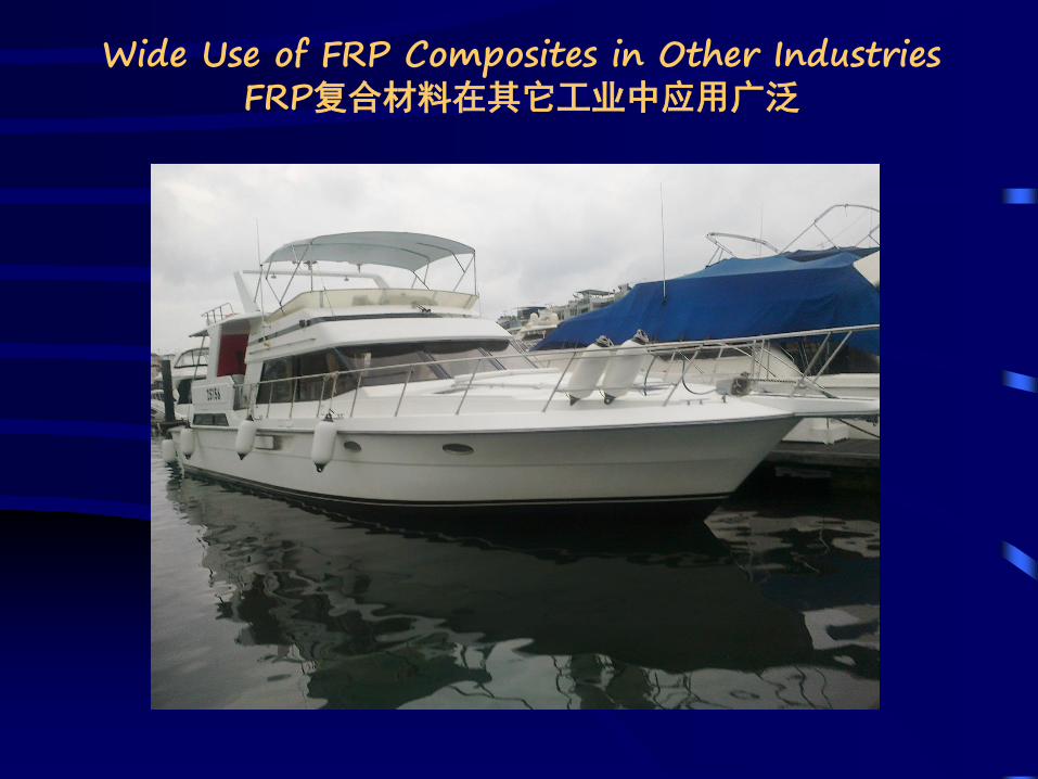
Wide Use of FRP Composites in Other IndustriesFRP复合材料在其它工业中应用广泛
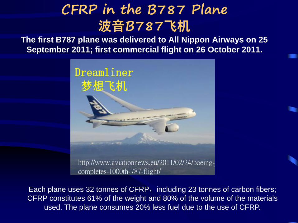
CFRP in the B787 Plane波音B787飞机
The first B787 plane was delivered to All Nippon Airways on 25
September 2011; first commercial flight on 26 October 2011.
Each plane uses 32 tonnes of CFRP,including 23 tonnes of carbon fibers;
CFRP constitutes 61% of the weight and 80% of the volume of the materials
used. The plane consumes 20% less fuel due to the use of CFRP.
Dreamliner梦想飞机
http://www.aviationnews.eu/2011/02/24/boeing-completes-1000th-787-flight/
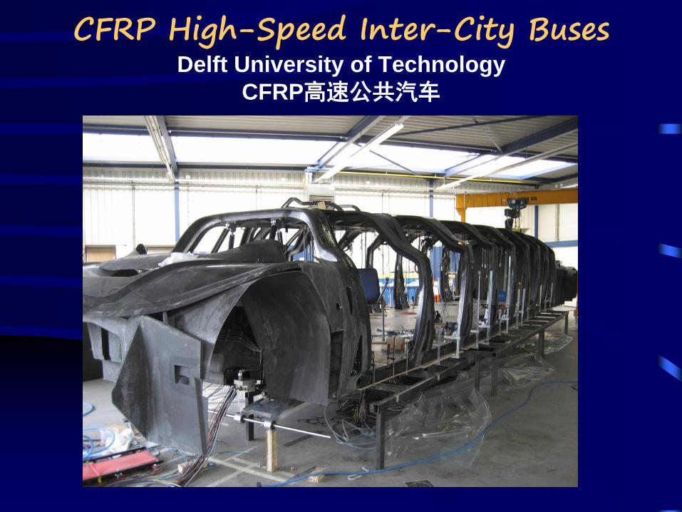
CFRP High-Speed Inter-City BusesDelft University of Technology
CFRP高速公共汽车
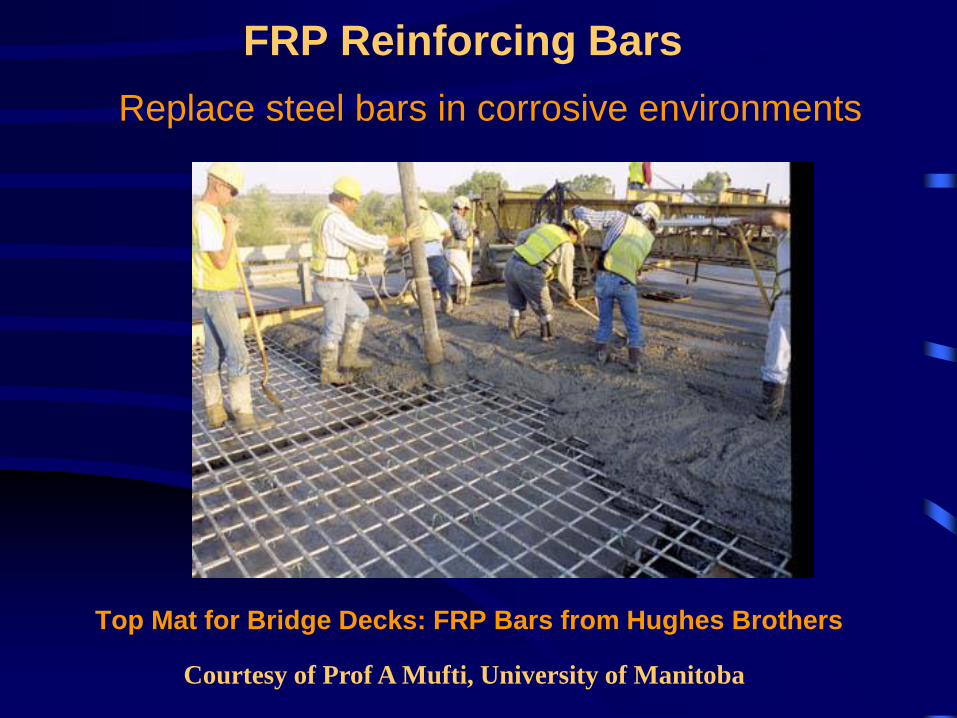
FRP Reinforcing Bars
Top Mat for Bridge Decks: FRP Bars from Hughes Brothers
Replace steel bars in corrosive environments
Courtesy of Prof A Mufti, University of Manitoba

MANITOBA FLOODWAY PROJECTSTEEL-FREE CONSTRUCTION
Modified from a slide provided by Prof. Aftab Mufti
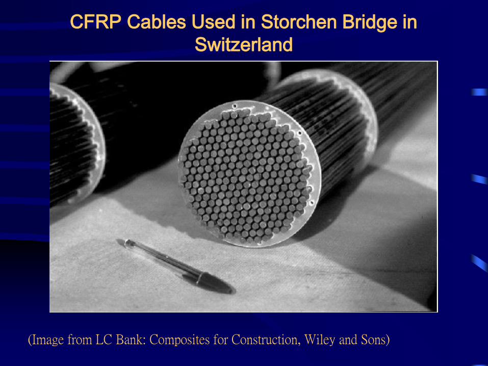
CFRP Cables Used in Storchen Bridge in
Switzerland
(Image from LC Bank: Composites for Construction, Wiley and Sons)
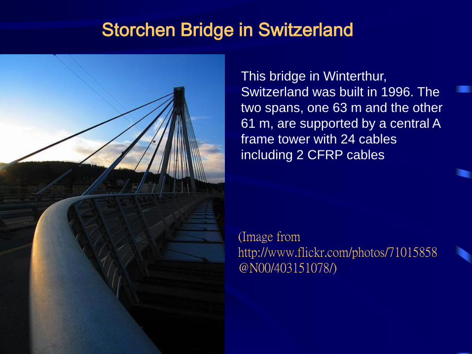
Storchen Bridge in Switzerland
This bridge in Winterthur,
Switzerland was built in 1996. The
two spans, one 63 m and the other
61 m, are supported by a central A
frame tower with 24 cables
including 2 CFRP cables
(Image from http://www.flickr.com/photos/71015858@N00/403151078/)
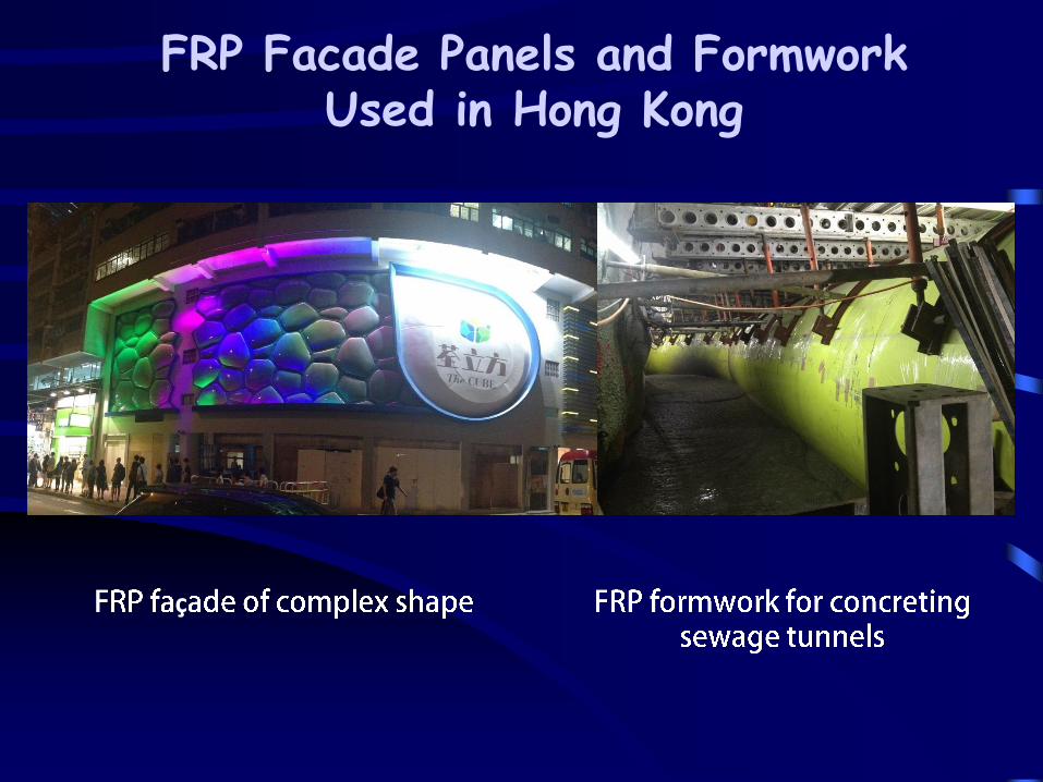
FRP Facade Panels and FormworkUsed in Hong Kong
ç
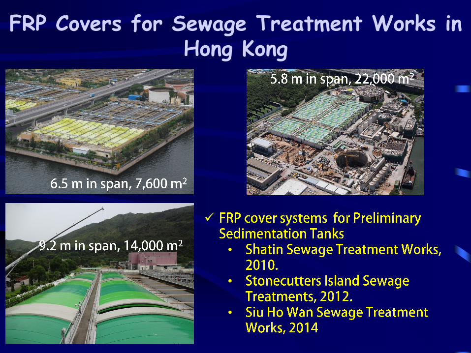
FRP Covers for Sewage Treatment Works in Hong Kong
•
•
•
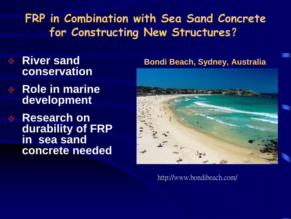
FRP in Combination with Sea Sand Concrete for Constructing New Structures?
River sand conservation
Role in marine development
Research on durability of FRP in sea sand concrete needed
http://www.bondibeach.com/
Bondi Beach, Sydney, Australia
FRP-enabled Hybrid Structures
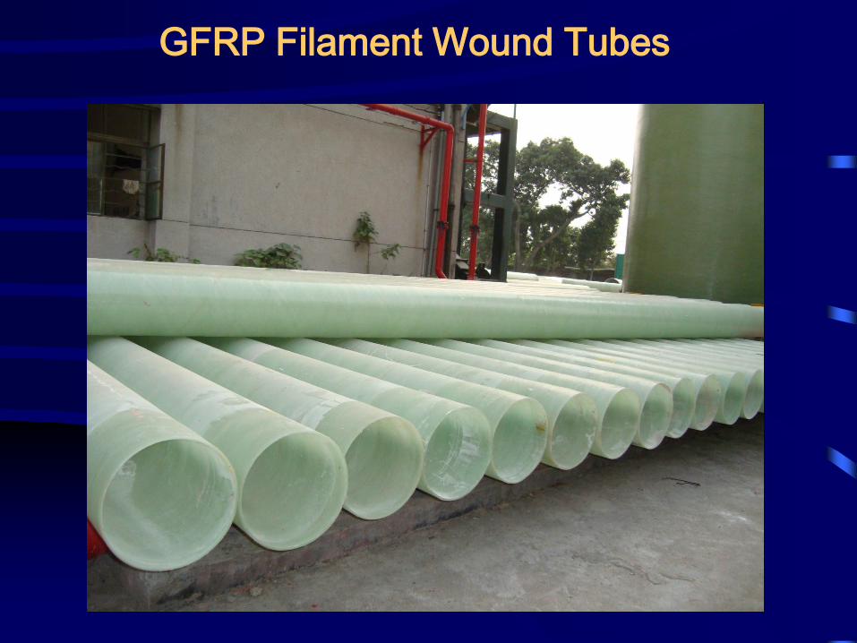
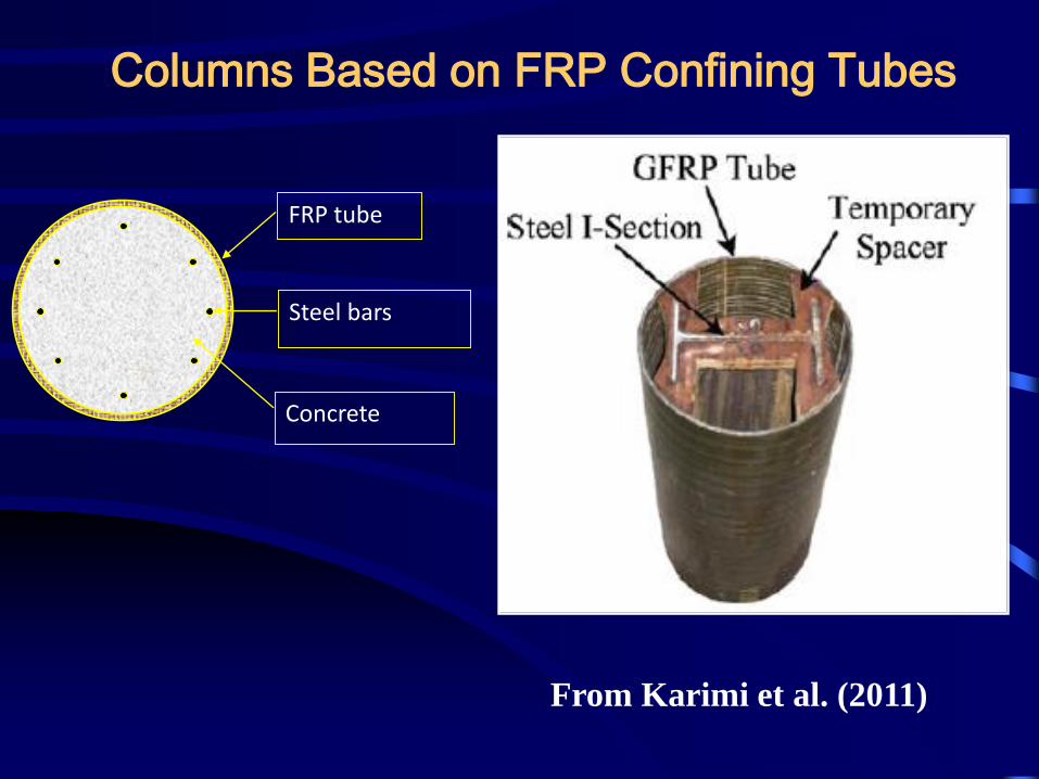
GFRP Filament Wound Tubes
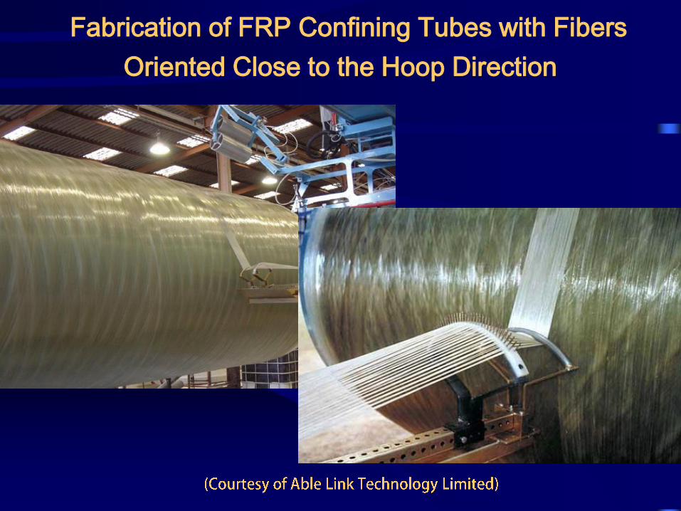
Fabrication of FRP Confining Tubes with Fibers
Oriented Close to the Hoop Direction
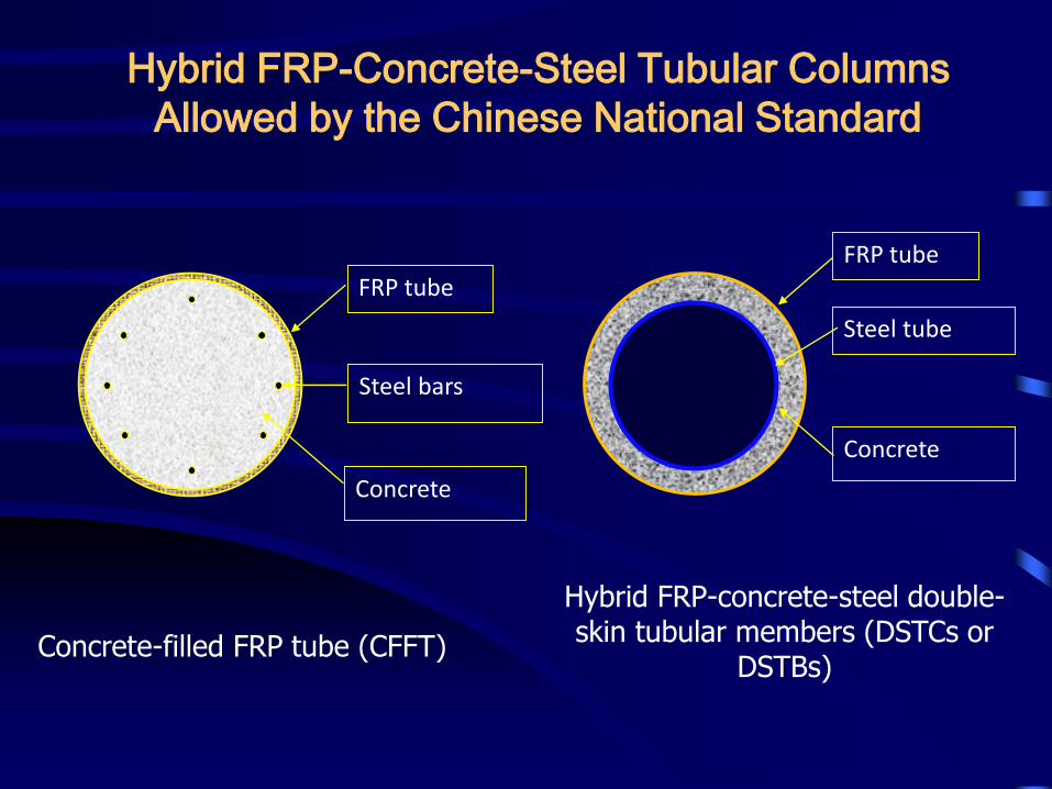
Hybrid FRP-Concrete-Steel Tubular Columns
Allowed by the Chinese National Standard
Concrete-filled FRP tube (CFFT)
FRP tube
Concrete
Steel tube
Steel bars
FRP tube
Concrete
Hybrid FRP-concrete-steel double-skin tubular members (DSTCs or
DSTBs)
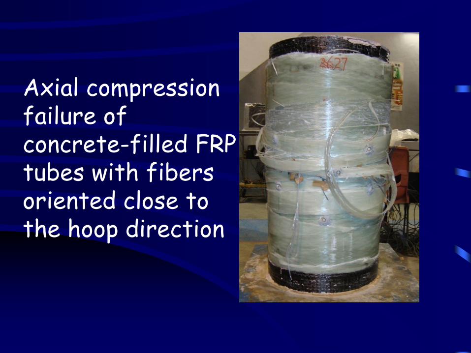
Axial compression failure of concrete-filled FRP tubes with fibers oriented close to the hoop direction
Steel bars
FRP tube
Concrete
From Karimi et al. (2011)
Columns Based on FRP Confining Tubes
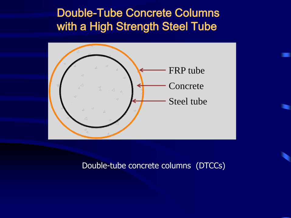
Double-tube concrete columns (DTCCs)
FRP tube
Concrete
Steel tube
Double-Tube Concrete Columns
with a High Strength Steel Tube
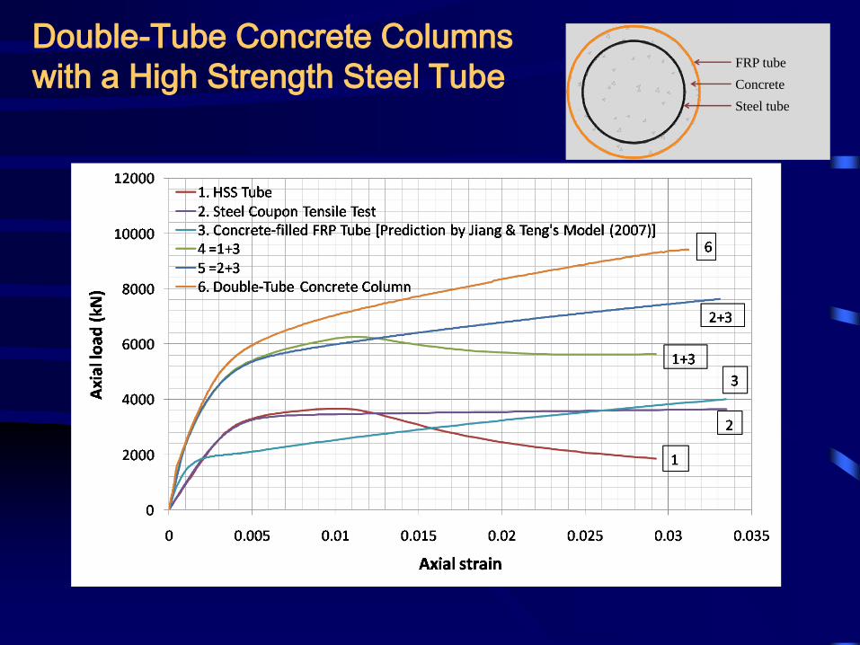
Double-Tube Concrete Columns
with a High Strength Steel TubeFRP tube
Concrete
Steel tube
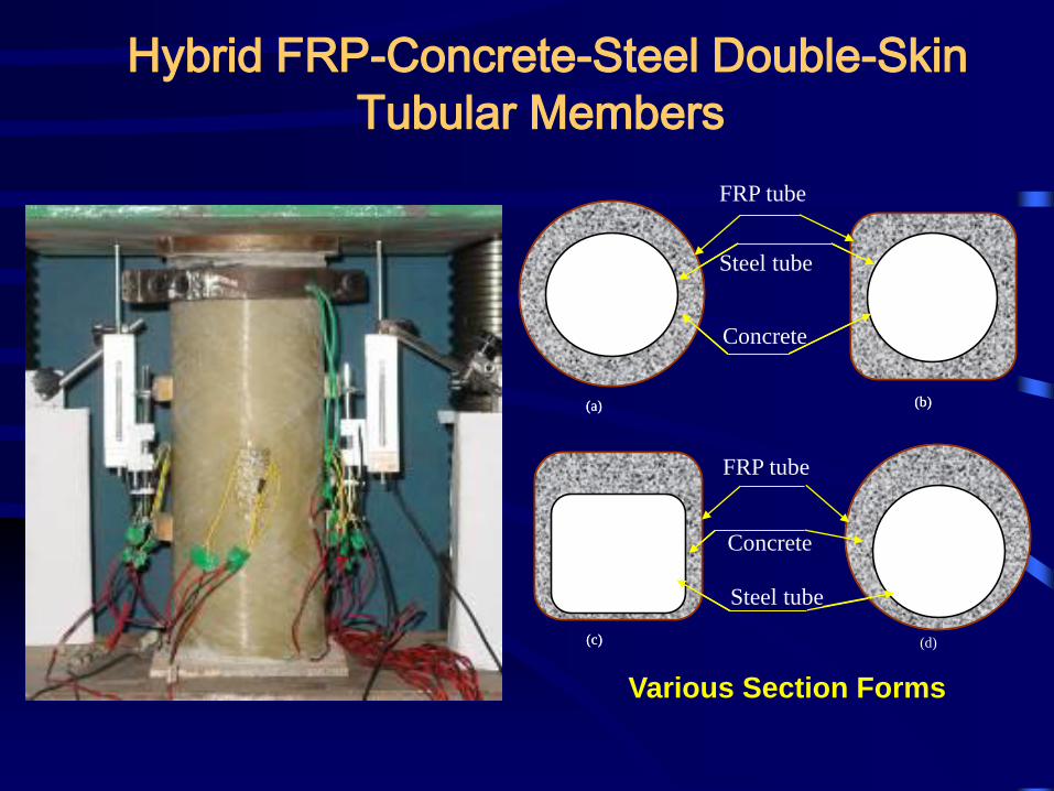
Hybrid FRP-Concrete-Steel Double-Skin
Tubular Members
Various Section Forms
FRP tube
Steel tube
Concrete
FRP tube
Concrete
Steel tube
(a) (b)
(c) (d)
(a) (b)
(c)
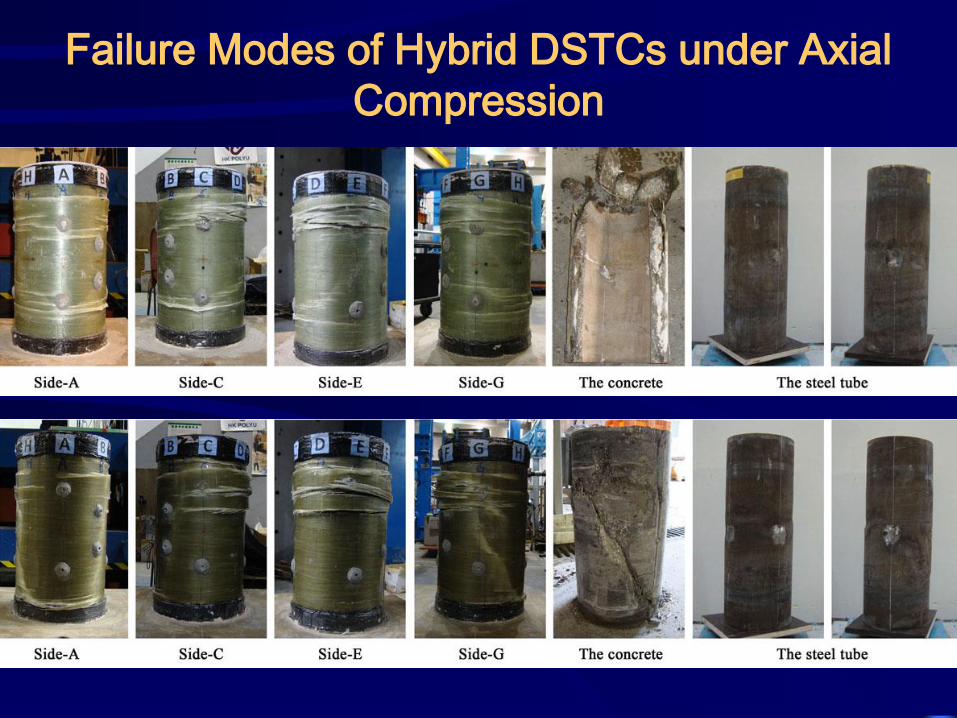
Failure Modes of Hybrid DSTCs under Axial
Compression
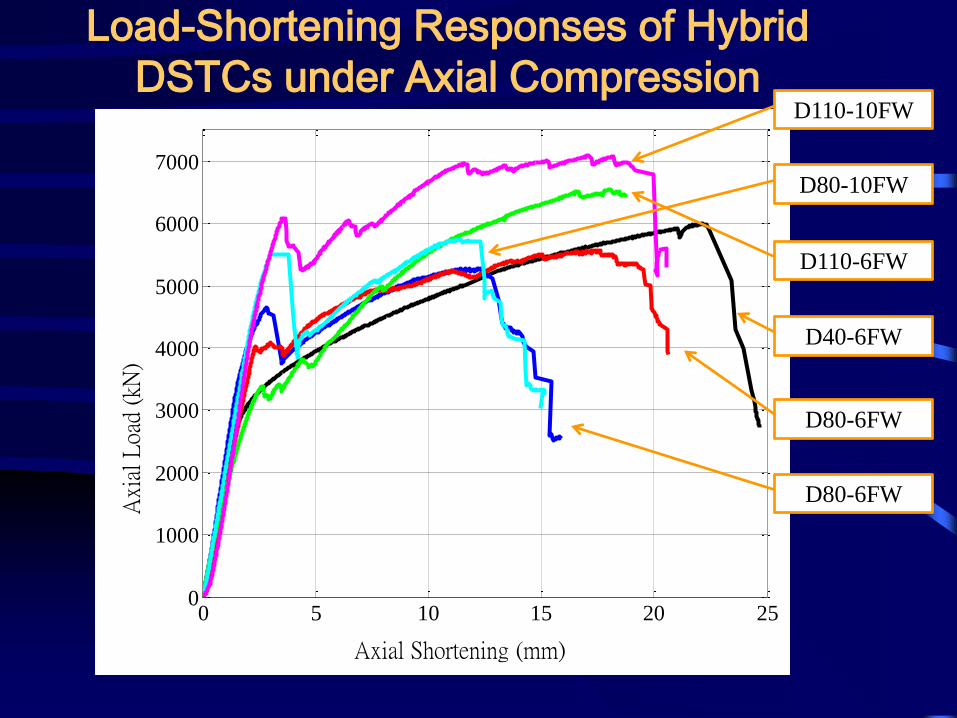
0 5 10 15 20 250
1000
2000
3000
4000
5000
6000
7000
Axial Shortening (mm)
Axi
al L
oad
(kN
)
D40-6FW
D80-6FW
D80-6FW
D110-6FW
D80-10FW
D110-10FW
Load-Shortening Responses of Hybrid
DSTCs under Axial Compression
Vertical actuator
Top plate
Bottom plate
Hinge
Column head fixture
Hinge
Horizontal actuator
Steel bolts
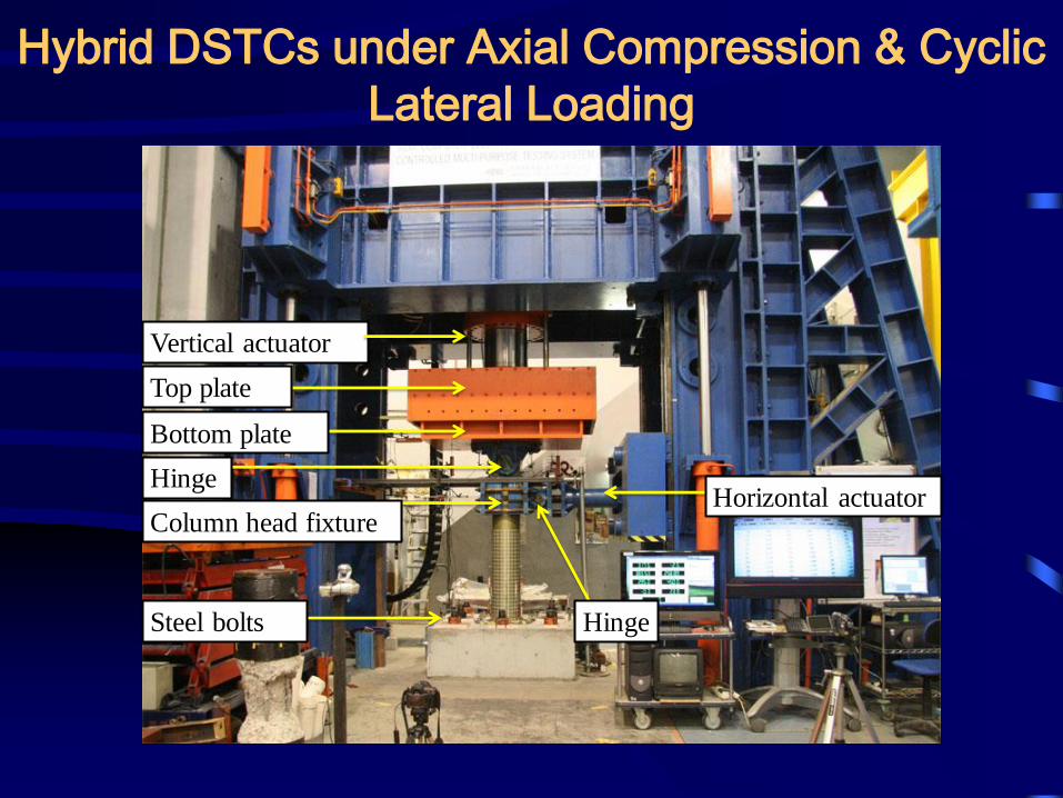
Hybrid DSTCs under Axial Compression & Cyclic
Lateral Loading
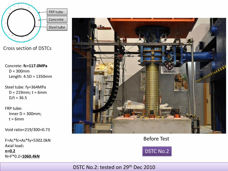
DSTC No.2: tested on 29th Dec 2010
Concrete: fc=117.0MPaD = 300mmLength: 4.5D = 1350mm
Steel tube: fy=364MPaD = 219mm; t = 6mmD/t = 36.5
FRP tube: Inner D = 300mm;t = 6mm
Void ratio=219/300=0.73
F=Ac*fc+As*fy=5302.0kNAxial load:n=0.2N=F*0.2=1060.4kN
DSTC No.2
Before Test
Department of Civil and Environmental Engineering
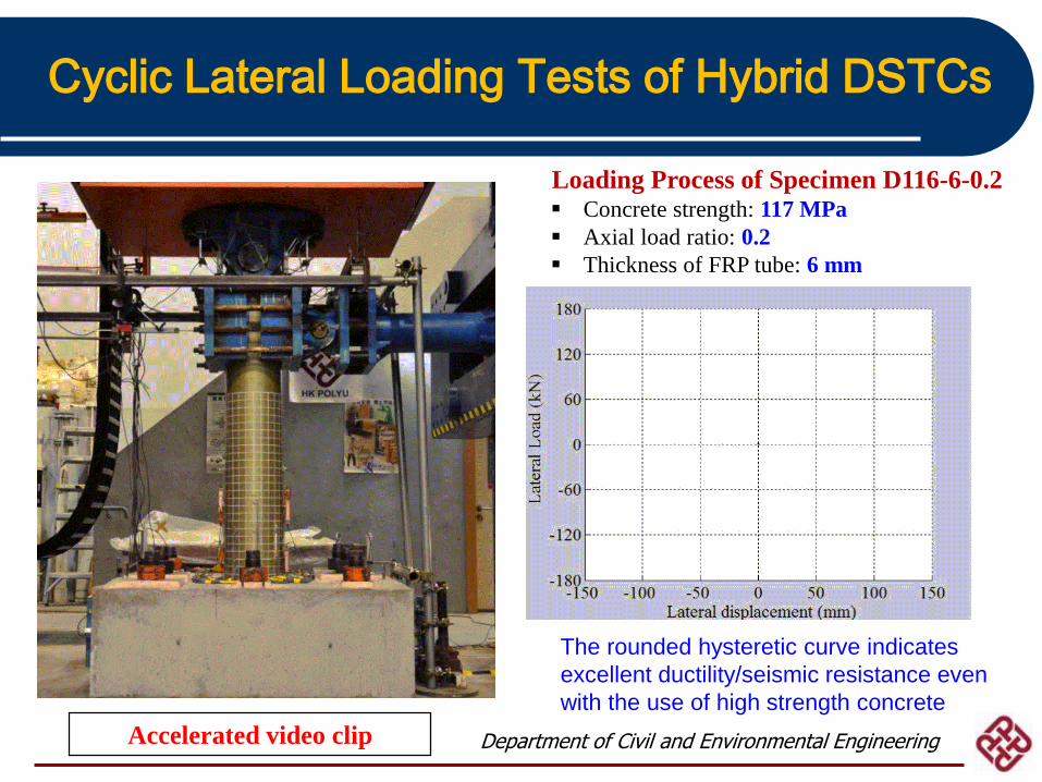
Cyclic Lateral Loading Tests of Hybrid DSTCs
The rounded hysteretic curve indicates
excellent ductility/seismic resistance even
with the use of high strength concrete
Loading Process of Specimen D116-6-0.2 Concrete strength: 117 MPa
Axial load ratio: 0.2
Thickness of FRP tube: 6 mm
Accelerated video clip
Department of Civil and Environmental Engineering
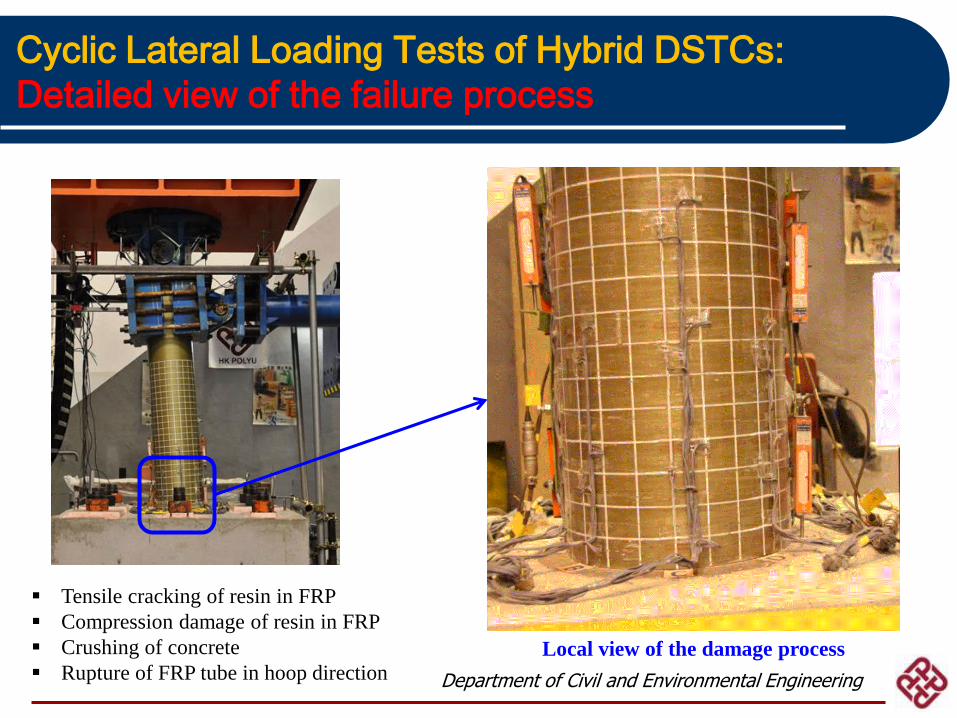
Cyclic Lateral Loading Tests of Hybrid DSTCs:
Detailed view of the failure process
Local view of the damage process
Tensile cracking of resin in FRP
Compression damage of resin in FRP
Crushing of concrete
Rupture of FRP tube in hoop direction
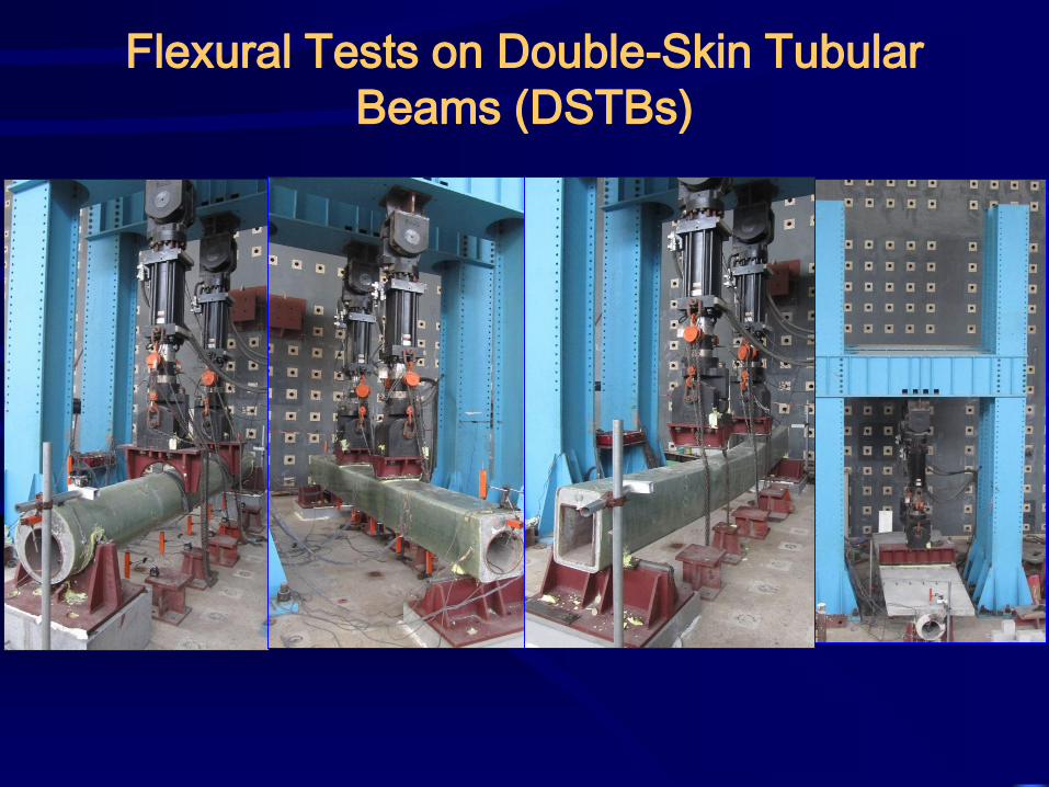
Flexural Tests on Double-Skin Tubular
Beams (DSTBs)
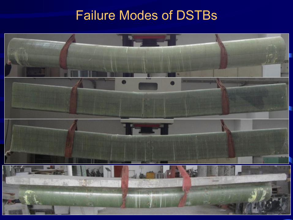
Failure Modes of DSTBs
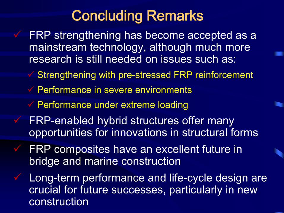
Concluding Remarks
FRP strengthening has become accepted as a mainstream technology, although much more research is still needed on issues such as:
Strengthening with pre-stressed FRP reinforcement
Performance in severe environments
Performance under extreme loading
FRP-enabled hybrid structures offer many opportunities for innovations in structural forms
FRP composites have an excellent future in bridge and marine construction
Long-term performance and life-cycle design are crucial for future successes, particularly in new construction

Acknowledgements
Funding support from the following organizations is gratefully acknowledged:
Research Grants Council of Hong Kong SAR
National Natural Science Foundation of China
Ministry of Science and Technology of China
Innovation and Technology Fund of Hong Kong SAR
The Hong Kong Polygenic University
Thanks are also due to the collaborators and members of my research group


![TANK TAMADA FRP TANK LINING FRp5y53d:Y5 (SS400) 1 1 Okliõ5Y5] TAMAOA 20 Ë5 FRP (Fiber Reinforced Plasutic) rîü+FRPJ AQUA ANGEL x —J ñ— L]" -F920-0332 (076) 267-4888 FAX (076)](https://img.pdfslide.tips/doc/110x75/5e90e672c1c33a79ff2ec9ee/tank-tamada-frp-tank-lining-frp5y53dy5-ss400-1-1-okli5y5-tamaoa-20-5-frp.jpg)