Embed Size (px)
Citation preview
Information Technology
Structured Cabling & Infrastructure
Standards
Revision Date: 06/11/2015
TABLE OF CONTENTS
I. PART 1 – General
1.01 Description ……………………………………… 1
1.02 Quality Assurance ……………………………… 1
1.03 Regulatory Requirements …………………….… 2
1.04 Abbreviations …………………………………... 3
1.05 Submittals ……………………………………… 3
II. PART 2 – Products
2.01 General …………………………………………. 4
2.02 Telecom Room (MDF/IDF) Termination ……… 6
2.03 Cable Routing/Pathway ………………………… 8
2.04 Station Wiring ………………………………….. 8
2.05 Station Hardware ………………………………. 9
2.06 Fiber Optic Products …………………………… 10
III. PART 3 – Execution
3.01 General …………………………………….…… 11
3.02 Documentation ………………………………… 12
3.03 Equipment Rack Configuration ……………….. 14
3.04 Station Wiring Installation ……………….……. 15
3.05 Station Hardware ………………………….…… 16
3.06 Fiber Optic Installation …………………….….. 16
3.07 Cable Testing Requirements ……………….….. 17
3.08 Inspection …………………………………..….. 18
IV. PART 4 – Appendix 4.01 IDF/MDF Standards ……………………….….. 19
4.02 Wireless Access Points….………………….….. 20
4.03 Voice over IP Phones.….………………….…... 20
4.04 Figure 2: Sample IDF Rack Layout & Electrical. 21
HCC STRUCTURED CABLING STANDARDS PART 1 - GENERAL
1.01 DESCRIPTION
A. Structured Cabling Standard Summary:
Houston Community College – Information Technology (HCC-IT) has established the structured cabling standard to ensure consistently high quality voice, data and video services at all HCC locations. The structured cabling standard is a complete and tested Systimax, category 6, cable distribution system for video, voice and data local area network (LAN) interconnections. The voice and data distribution system shall include fully terminated unshielded twisted pair cables, raceway, conduit, IDC termination devices, voice and data communications outlets, patch panels, patch cables, racks, and other incidental and miscellaneous wiring system hardware as required for a complete and usable video, voice & data network system.
Each Telecommunications Room (TR or IDF) will connect to the Main Equipment Room (MER or MDF) via 24-strand Multimode OM4 (MM) fiber optic cable for data/VoIP, and 25 pair Cat 3 copper (plenum rated) riser cable for voice as indicated in the project RFP/RFQ or as specified by and authorized Houston Community College-Information Technology (HCC-IT) representative.
Inter-building connections will be via Singlemode (SM) fiber optic cable. The SM fiber cable specifications will be as indicated in the project RFP/RFQ or as specified by and authorized HCC-IT representative
The installation of all cable shall comply with all applicable local, state, NEC, EIA/TIA and BICSI codes & standards and as indicated by project drawings and specifications.
1.02 QUALITY ASSURANCE
A. Installer Qualifications:
The Video, Voice and Data (LAN) System installer shall be licensed and shall meet all applicable regulations of the State of Texas and Department of Labor as they apply to this type of cable system installation. The installer shall be a firm normally employed in the low voltage - video, voice and data cabling industry and shall provide a reference list of at least ten (10) large-scale projects and contact names confirming successful video, voice and/or Category 6 or higher data (LAN) cable system installations. Large-scale projects shall be defined as projects involving at least 100, Category 6 or higher, cabling runs per site.
B. Pre-Construction Meeting:
The installer shall attend a mandatory pre-construction meetings with individuals deemed necessary by the HCC representative prior to the start of the work.
C. Acceptance:
The HCC representative reserves the right to reject all or a portion of the work performed, either on technical or aesthetic grounds.
Rev 06/11/2015 - page 1
HCC STRUCTURED CABLING STANDARDS
D. Warranty:
The selected cable system installer shall be a factory certified SYSTIMAX Value Added Reseller (VAR) and shall provide a SYSTIMAX end-to-end performance warranty of not less than twenty (20) years. The cable system installer must provide Systimax certification documentation prior to the start of work. The performance warranty shall be issued by the manufacturer, and a workmanship warranty shall be issued by the cable installer which shall warrant that ALL voice and/or data Category 6 links have been bi-directionally (end to end) tested using a Level 2 tester, per TSB-67, and that all test results conform to the most current EIA/TIA-568-B and TSB-67 Link standards.
The warranty will also cover Singlemode and Multimode fiber optic cabling. Performance testing shall be conducted in accordance with EIA/TIA-526-14 standards.
The warranty will stipulate that all products used in this installation meet the prescribed mechanical and transmission specifications for such products as described in ISO/IEC 11801, EIA/TIA-568-B. Quality and workmanship evaluation shall be solely by HCC designated representatives and SYSTIMAX.
1.03 REGULATORY REQUIREMENTS
A. Standards: All work shall be performed in accordance with the latest revisions of the following standards and codes:
1. Latest Local Codes and Amendments 2. 2008 National Electrical Code
B. Other References:
1. EIA/TIA-568-B Commercial Building Telecommunications Wiring Standard. 2. EIA/TIA-569-A Commercial Building Standard for Telecommunication
pathways and spaces. 3. EIA/TIA-606-A Administration Standard for the Telecommunications
4.
EIA/TIA-607-A
Infrastructure of commercial buildings. Commercial Building Grounding and Bonding Requirements
for Telecommunications. 5. EIA/TIA-455-A Standard test procedure for fiber optic cables, Transducers,
sensors, connecting and terminating devices and other fiber- optic components. 6. EIA/TIA TSB-67 Transmission performance specification for field testing of
unshielded twisted pair cabling systems. 7. EIA/TIA TSB-72 Centralized Optical Fiber guidelines. 8. ISO/IEC 11801 Generic Cabling standard. 9. EIA/TIA 526-14 Optical power loss measurements of installed Multimode fiber
cable plan.
C. Governing Codes and Conflicts:
If the requirements of these specifications or the project drawings exceed those of the governing codes and regulations, then the requirements of these specifications and the drawings shall govern. However, nothing in the drawings or specifications shall be construed to permit work not conforming to all governing codes and regulations.
Rev 06/11/2015 - page 2
HCC STRUCTURED CABLING STANDARDS
1.04 ABBREVIATIONS
A. The following abbreviations are used in this document:
DC Direct Current TR or IDF Telecommunications Room MER or MDF Main Equipment Room PBX Private Branch Exchange UTP Unshielded Twisted Pair IDC Insulation Displacement Connection I/O Information Outlet(s) CAM Video Surveillance Camera GW Physical Access Gateway ENC Analog to Digital Video Encoder
1.05 SUBMITTALS
A. Project Initiation:
Within ten (10) working days of Notice to Proceed, the cable system installer shall furnish the following in a single consolidated submittal to HCC-IT:
1. Construction Schedule: A time-scaled Construction Schedule, using PERT/CPM,
Microsoft Project or equivalent indicating general project deadlines/milestones and specific dates relating to the installation of the cable distribution system.
2. Permits: The cable system installer shall obtain all required permits, if required by state
and local law.
3. Product Literature: Complete manufacturer's product literature for all cable, patch panels, cross-connect blocks, cable supports, cable labels, outlet devices, and other products to be used in the installation. In addition, whenever substitutions (when requested by the HCC-IT/Designer) for recommended products are made, samples and the manufacturer's supporting documentation demonstrating compatibility with other related products must be included.
B. Installation Plan:
Submit the following items, for HCC-IT review and approval, within ten (10) working days of notice to proceed:
1. Cable Routing: Proposed cable routing and cable grouping plan prepared by a BICSI
certified RCDD (Registered Communications Distribution Designer). The RCDD certification must be current.
2. Conformance: For items that are not as specified, provide standard manufacturer's cut
sheets or other descriptive information and a written description detailing the reason for the substitution. Substitutions are subject to HCC-IT approval.
3. Working “as -built” Drawings : Provide HCC-IT a preliminary “as-built” drawing set via
email, disk, flash memory or two (2) Mylar plots of each drawing. The preliminary “as- built” drawings will include cable pathways, voice & data outlets, room numbers, and MDF/IDF locations with correct labeling. This “as-built” drawing will be utilized by HCC- IT to configure network & telephony equipment.
Rev 06/11/2015 - page 3
HCC STRUCTURED CABLING STANDARDS
C. Project Completion:
As a condition for project acceptance, the cable system installer shall submit the following for review and approval:
1. Samples: Complete manufacturer's product literature and samples (if requested) for all
pre-approved substitutions to the recommended products made during the course of the Project.
2. Inspection and Test Reports: During the course of the project, the cable system installer
shall maintain an adequate inspection system to insure that the materials supplied and the work performed conforms to contract requirements. The cable system installer shall provide written documentation that indicates materials acceptance testing was conducted as specified. The cable system installer shall also provide documentation, which indicates that all cable termination testing was completed and that all irregularities were corrected prior to job completion. Test data will be provided on disk and/or hardcopy.
3. Operating and Maintenance Instructions: Operating and maintenance instructions for all
devices within the system. These instructions shall reflect any changes made during the course of construction, and shall be provided to the HCC-IT for their use in a three-ring binder labeled with the project name and description (1 copy unless otherwise specified by HCC-IT).
4. Final “as-built” Drawings: As-built drawings will include cable pathways, data outlet
locations with correct labeling, room numbers, and MDF/IDF locations. The as-built drawings will be prepared using AutoCAD version 14 or later. Provide HCC-IT with electronic versions of the as-built drawings via email, CD, DVD or flash drive.
PART 2 - PRODUCTS
2.01 GENERAL
A. Installation:
The cabling system shall be installed per requirements of BICSI standards, recommendations of the manufacturer and the project documents, utilizing materials that meet all applicable EIA/TIA standards. The cable system installer shall also be responsible for meeting all city and state codes. The cable system installer is responsible for providing all incidental and /or miscellaneous hardware not explicitly specified as required for a complete operating system.
B. Materials:
Materials shall be as listed or shall be approved equivalent products of other manufacturers meeting the intent and quality level of the EIA/TIA standards. All approved equivalent products will be published by addendum for approval ten (10) days prior to installation for HCC-IT.
Rev 06/11/2015 - page 4
HCC STRUCTURED CABLING STANDARDS
C. Testing:
All installed cabling shall be tested 100% good, via Level II test equipment, after installation and prior to job completion by the cable system installer.
D. Ratings:
All products shall be new and brought to the job site in the original manufacturer's packaging. Electrical components (including inner duct) shall bear the Underwriter's Laboratories (UL) label. All communications systems cable shall bear flammability testing ratings as follows:
1. CM Communications Cable 2. CMP Plenum Rated Communications Cable 3. CMR Riser-Rated Communications Cable
E. Initial Cable Inspection:
The cable system installer shall inspect all cable prior to installation to verify that it has been identified properly on the reel identification label; it is of the proper gauge containing the correct number of pairs, etc. and is ready for installation. Damaged cable or any other components failing to meet specifications shall not be used in the installation.
F. Cable Lubricants:
Lubricants specifically designed for installing communications cable may be used to reduce pulling tension as necessary when pulling cable through conduit.
1. Approved Products for twisted-pair cable:
3M Green Lee HCC-IT Pre-approved equivalent
G. Fire Wall Sealant:
Any penetration through MDF/IDF and fire rated walls will be sleeved and sealed with an Underwriter Laboratories (UL) approved sealant and/or mechanical fire-proofing solution.
1. Approved Products:
3M Hilti System Fire Safe HCC-IT Pre-approved equivalent
Rev 06/11/2015 - page 5
HCC STRUCTURED CABLING STANDARDS
2.02 TELECOMM & MAIN EQUIPMENT ROOM (MDF/IDF) CABLING TERMINATION HARDWARE
A. Equipment and Distribution Racks: Provide and install equipment and distribution racks in locations indicated on telecommunications room design drawings or as indicated by HCC-IT. All racks shall be floor mounted, type 19” x 84” unless otherwise approved by HCC-IT.
1. Approved Products - Floor Mount Racks: Chatsworth Products, Inc. (CPI) #55053-703 Hoffman or equivalent HCC-IT Pre-approved equivalent
2. Approved Products - Wall Mount Enclosures: Hubbell Premise Wiring #HSQ3636 Hoffman or equivalent HCC-IT Pre-approved equivalent
3. Approved Products – Equipment Shelf for Two-Post Rack: Rack Solutions rack shelf 3-RU compatible with Hoffman rack HCC-IT Pre-approved equivalent
A two (2) RU horizontal wire management product will be installed in between each patch panel on the equipment racks. Additional horizontal wire managers will be provided for placement between network equipment, adjacent to patch panel racks, per HCC-IT Network and project requirements for patch cable management. Vertical cable managers should be 12” between racks, and 6” on rack ends. 1. Approved Products: Chatsworth Products, Inc. (CPI) #35441-702 Hoffman or equivalent HCC-IT Pre-approved equivalent
B. Equipment and Distribution Rack Grounding:
Equipment and distribution racks shall be grounded using a stranded #6 AWG insulated copper conductor. Ground wire will connect to the Telecommunications grounding bus bar in each respective MDF or IDF. The cable system installer shall provide all required bonding materials and hardware, and bond to the Telecommunications bonding backbone interconnecting conductor that is bonded to building grounding electrode subsystem at building electrical service entrance.
1. Approved Products: Chatsworth Products, Inc. (CPI) #08009-001 HCC-IT Pre-approved equivalent
C. Fiber Optic Patch Panels:
The enclosures used shall provide termination panels for duplex SC type connectors and be sufficient size and capacity to terminate 100% of all inside and outside fiber optic cables and in addition have enough for a 10% growth. Enclosures must be 19” rack mount compatible. The cable system installer will provide all termination accessories, enclosures and test data.
1. Approved Products:
Systimax 72 Port Fiber Termination Unit
Product/Part Code LST1F-072/7 Commercial Code 760 026 245
Rev 06/11/2015 - page 6
HCC STRUCTURED CABLING STANDARDS
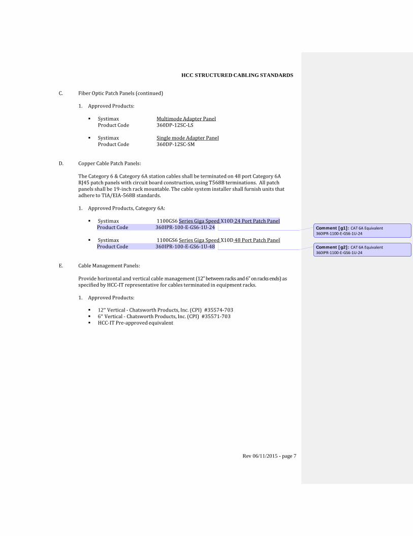
C. Fiber Optic Patch Panels (continued)
1. Approved Products:
Systimax Multimode Adapter Panel
Product Code 360DP-12SC-LS
Systimax Single mode Adapter Panel Product Code 360DP-12SC-SM
D. Copper Cable Patch Panels:
The Category 6 & Category 6A station cables shall be terminated on 48 port Category 6A RJ45 patch panels with circuit board construction, using T568B terminations. All patch panels shall be 19-inch rack mountable. The cable system installer shall furnish units that adhere to TIA/EIA-568B standards. 1. Approved Products, Category 6A:
Systimax 1100GS6 Series Giga Speed X10D 24 Port Patch Panel
Product Code 360IPR-100-E-GS6-1U-24
Systimax 1100GS6 Series Giga Speed X10D 48 Port Patch Panel Product Code 360IPR-100-E-GS6-1U-48
E. Cable Management Panels:
Provide horizontal and vertical cable management (12” between racks and 6” on racks ends) as specified by HCC-IT representative for cables terminated in equipment racks.
1. Approved Products: 12” Vertical - Chatsworth Products, Inc. (CPI) #35574-703 6” Vertical - Chatsworth Products, Inc. (CPI) #35571-703 HCC-IT Pre-approved equivalent
Comment [g1]: CAT 6A Equivalent 360IPR-1100-E-GS6-1U-24
Comment [g2]: CAT 6A Equivalent 360IPR-1100-E-GS6-1U-24
Rev 06/11/2015 - page 7
HCC STRUCTURED CABLING STANDARDS 2.03 CABLE ROUTING/PATHWAY
A. Cable Tray:
Metal cable tray shall be provided and affixed to the top of all floor-mounted racks as indicated in MDF/IDF layout drawings. Cable tray shall be used to brace racks to walls and to support cable routing from either ceilings or walls to the rack in the MDF/IDF rooms.
1. Approved Products:
Chatsworth Products, Inc. (CPI) 11252-712 Chatsworth Products, Inc. (CPI) 10822-712 And all applicable installation accessories HCC-IT Pre-approved equivalent
B. Cable Support System:
Cables not in conduit or cable tray shall be supported by BICSI/EIA/TIA approved supports. The Contractor shall provide and install the necessary quantity and size of CADDY Fastener “Cable CAT” hangers and support hardware necessary for routing all station cable bundles outside of cable tray systems. At a minimum, there shall be one “Cable CAT” hanger every 4 to 5 feet. Exact placement shall be dictated by Manufacturer’s installation guidelines and site conditions. Caddy-bags will be used for the larger trunks. Bridal rings are not to be used. Cables for physical security and life safety must not be exposed.
1. Approved Products:
Caddy Fasteners® or HCC-IT Pre-approved equivalent
Cable dressing will be required every two (2) to three (3) feet. Cables will be secured with Velcro® type wire wrap. Plastic tie/wire wraps are not permitted.
C. Outside Plant Pathways:
MaxCell OSP Mesh shall be installed in exterior conduit pathways for building-to-building communications tie cables.
1. Approved Products:
MaxCell OSP Mesh HCC-IT Pre-approved equivalent
2.04 STATION WIRING
A. Wire-Copper:
The wire provided for all outlets shall be Category 6 (Category 6A where indicated), Unshielded Twisted Pair (UTP), four- pair, 24 AWG solid copper conductor, meeting the intent and quality level of the EIA/ TIA -568-B Commercial Building Wire Standard. All Wireless Access Point (AP) wiring should consist of two Category 6A cables per designated AP location. Cable count to be confirmed with HCC-IT, per project plans.
Rev 06/11/2015 - page 8
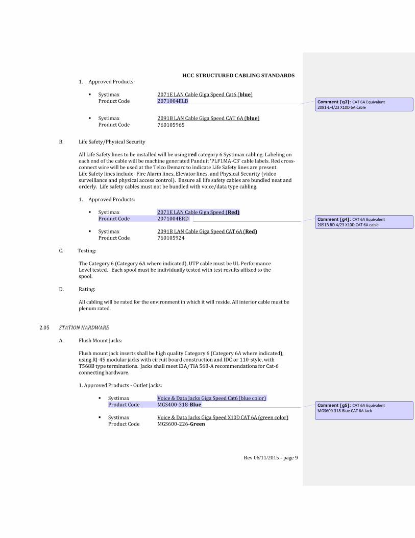
HCC STRUCTURED CABLING STANDARDS 1. Approved Products:
Systimax 2071E LAN Cable Giga Speed Cat6 (blue) Product Code
2071004ELB
Systimax 2091B LAN Cable Giga Speed CAT 6A (blue) Product Code
760105965
B. Life Safety/Physical Security
All Life Safety lines to be installed will be using red category 6 Systimax cabling. Labeling on each end of the cable will be machine generated Panduit ‘PLF1MA-C3’ cable labels. Red cross-connect wire will be used at the Telco Demarc to indicate Life Safety lines are present. Life Safety lines include- Fire Alarm lines, Elevator lines, and Physical Security (video surveillance and physical access control). Ensure all life safety cables are bundled neat and orderly. Life safety cables must not be bundled with voice/data type cabling. 1. Approved Products:
Systimax 2071E LAN Cable Giga Speed (Red)
Product Code 2071004ERD
Systimax 2091B LAN Cable Giga Speed CAT 6A (Red) Product Code 760105924
C. Testing:
The Category 6 (Category 6A where indicated), UTP cable must be UL Performance Level tested. Each spool must be individually tested with test results affixed to the spool.
D. Rating:
All cabling will be rated for the environment in which it will reside. All interior cable must be plenum rated.
2.05 STATION HARDWARE
A. Flush Mount Jacks:
Flush mount jack inserts shall be high quality Category 6 (Category 6A where indicated), using RJ-45 modular jacks with circuit board construction and IDC or 110-style, with T568B type terminations. Jacks shall meet EIA/TIA 568-A recommendations for Cat-6 connecting hardware.
1. Approved Products - Outlet Jacks:
Systimax Voice & Data Jacks Giga Speed Cat6 (blue color)
Product Code MGS400-318-Blue
Systimax Voice & Data Jacks Giga Speed X10D CAT 6A (green color) Product Code MGS600-226-Green
Comment [g3]: CAT 6A Equivalent 2091-L-4/23 X10D 6A cable
Comment [g4]: CAT 6A Equivalent 2091B RD 4/23 X10D CAT 6A cable
Comment [g5]: CAT 6A Equivalent MGS600-318-Blue CAT 6A Jack
Rev 06/11/2015 - page 9
HCC STRUCTURED CABLING STANDARDS
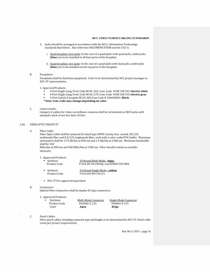
2. Jacks should be arranged in accordance with the HCC/ Information Technology standards that follow. Also reference DOCUMENTATION section 3.02-A.
i. Quad faceplate, four jacks: In the case of a quad plate with quad jacks, outlet jacks
(blue) are to be installed in all four ports of the faceplate.
ii. Quad faceplate, two jacks: In the case of a quad plate with dual jacks, outlet jacks (blue) are to be installed on the top ports of the faceplate.
B. Faceplates:
Faceplates shall be Systimax equipment. Color to be determined by HCC project manager or HCC-IT representative.
1. Approved Products: 4-Port Single Gang, Prod. Code M14L-262, Com. Code #108 168 543-electric white 4-Port Single Gang, Prod. Code M14L-270, Com. Code #108 168 535-electric gray 3-Port Cubicle Faceplate M13C-003 Com Code # 106650864- Black * Note: Com. Code may change depending on color.
C. Camera Jacks: Category 6 cables for video surveillance cameras shall be terminated on RJ45 jacks with
adequate slack of not less than 10 feet.
2.06 FIBER OPTIC PRODUCTS
A. Fiber Cable: Fiber Optic Cable shall be armored UL listed type OFNP; twenty four strand, 50/125, multimode fiber and 8.3/125 singlemode fiber, each with a color-coded PVC buffer. Maximum attenuation shall be 3.75 dB/km at 850 nm and 1.5 dB/km at 1300 nm. Minimum bandwidth shall be 160 MHz/km at 850 nm and 500 MHz/km at 1300 nm. Fiber should contain no metallic elements.
1 . Approved Products: Systimax 24 Strand Multi-Mode –Aqua
Product Code P-024-DS-5K-FSUAQ–LazrSPEED 550 OM4
Systimax 24 Strand Single-Mode - yellow Product Code P-024-DS-8W-FSUYL
HCC-IT Pre-approved equivalent
B. Connectors: Optical Fiber Connectors shall be duplex SC type connectors.
1 . Approved Products: Systimax Multi-Mode Connector Single-Mode Connector
Product Code P6200A-Z_125 P6000A-Z-125 Color Aqua Beige
.
C. Patch Cables: Fiber patch cables, including connector type and length, to be determined by HCC-IT. Patch cable count per project requirements.
Rev 06/11/2015 - page 10
HCC STRUCTURED CABLING STANDARDS PART 3 - EXECUTION
3.01 GENERAL
A. Wall Penetrations:
The cable system installer shall avoid penetration of fire-rated walls and floors wherever possible. Where penetrations are necessary, they shall be sleeved with metallic conduit, bushings installed on both ends, and resealed with a UL approved fire rated sealant and/or mechanical fire-proofing solution. Cable system installer shall also seal all floor, ceiling and wall penetrations in fire or smoke barriers and in wiring telecommunication and equipment rooms (IDF/MDF).
B. Allowable Cable Bend Radius and Pull Tension:
In general, communications cable cannot tolerate sharp bends or excessive pull tension during installation. Refer to the Systimax’s bend radius recommendations for the maximum allowable limits.
C. Cable Lubricants:
After installation, exposed cable and other surfaces must be cleaned free of lubricant residue.
D. Pull Strings:
Provide pull strings (approved jet-line or mule-line) in all new conduits, including all conduits with cable installed as part of this contract.
E. Conduit Fill:
Conduit fill shall not exceed 40%. Reference the TIA/EIA Design and Installation Guidelines.
F. Damage:
1. The cable system installer shall replace or rework cables showing evidence of improper handling including stretches, kinks, short radius bends, over-tightened bindings, loosely twisted and over-twisted pairs at terminals and cable sheath removed too far (greater than 1/2 inch).
2. The cable system installer shall be responsible for any damage to the network,
equipment and or facility that occurred during the cable system installation.
G. Clean Up:
All clean up activity related to work performed will be the responsibility of the cable system installer and must be completed daily before leaving the facility.
Rev 06/11/2015 - page 11
HCC STRUCTURED CABLING STANDARDS
3.02 DOCUMENTATION
A. Labels and Outlet Jack Placement:
The cable system installer will label all information outlets using permanent machine generated labels approved by the HCC-IT representative. Handwritten labels are not permitted. Label all patch panels in the telecommunication and equipment room(s) to match those on the corresponding voice and data outlets. The font shall be at least one-eighth inch (1/8") in height, block. All labels shall correspond to as-built drawing and to final test reports. Each cable shall be labeled at the work station within 1” of termination with machine generated labels. This is an addition to the labeling of the wall plate. All wireless access point drops hidden behind ceiling tiles shall be labeled on the corresponding ceiling grid with clear labels.
To meet HCC standards, telecommunication outlet faceplates should be labeled and constructed as follows:
1. In the case of a QUAD plate with QUAD jacks; outlet jacks will be installed in all four
ports. See Figure 1 below, section 3.02-A-8.
2. General jack placement in quad faceplate is shown in figure 1 under the face plate port layout section.
3. In the case of a single network jack, utilize the upper left side port and insert blanks into unused outlets.
4. Labels should be self-adhesive. Outlets should have non-embossed area for label
placement to ensure label will adhere properly.
5. Labels are to be machine generated. Handwritten labels are unacceptable and will not be used.
6. Do not duplicate existing cable number identifications. New patch panel jack numbers
shall be numbered in continuation to any existing identification numbers and must be coordinated with HCC-IT.
• Example: If existing numbers are 1-40, new identification numbers should start at
41.
7. The following label nomenclature should be used. Identification labels must be coordinated with HCC-IT prior to printing and placement:
• Telecom Room Example: T2B-001
T - Telecommunication Room (TR or IDF) 2 - Floor Identifier – 2nd floor B - IDF room B on floor level (A, B, C, etc.) 001 - Cable Number
• Main Equipment Room Example: M2-025
M - Main Equipment Room (MER or MDF) 2 - Floor Identifier – 2nd floor 025 - Cable Number
Rev 06/11/2015 - page 12
HCC STRUCTURED CABLING STANDARDS
8. Faceplate Port Layout:
Legend J - Outlet Jack B – Blank Insert J B
QUAD
Faceplate
B B
J J
QUAD Faceplate B B
J J
QUAD Faceplate
J B Figure 1
J J
QUAD Faceplate J J
B. Labeling of Life Safety Cables at Patch Panel and Jack
The cable system installer will label all life safety outlets using permanent machine generated labels approved by the HCC-IT representative. Handwritten labels are not permitted. Label all patch panels in the telecommunication and equipment room(s) to match those on the corresponding camera jacks. The font shall be at least one-eighth inch (1/8") in height, block. All labels shall correspond to as-built drawing and to final test reports. Each cable shall be labeled on the jack at the camera end with machine generated labels. The following label nomenclature should be used. Identification labels must be coordinated with HCC-IT prior to printing and placement:
• Example: CAM-101
CAM - Camera 1 - Floor Identifier – 1st floor 01 - Camera Number
• Example: GW-201
GW – Physical Access Control Gateway 2 - Floor Identifier – 2nd floor B - IDF room B on floor level (A, B, C, etc.) 01 – Gateway Number
C. Floor Plan Drawing:
A floor plan drawing, clearly labeled with all outlet jack numbers shall be included in the as- built plans. See section 1.05, C-4.
Rev 06/11/2015 - page 13
HCC STRUCTURED CABLING STANDARDS
3.03 EQUI
A.
PMENT RACK CONFIGURATION
Equipment Racks:
Equipment racks shall be assembled and mounted in locations shown on project drawings and verified with HCC-IT prior to installation. Each rack shall be securely mounted to the
floor and braced to the wall with shall be mounted such that the side rails are plumb with vertical cable management panels.
Racks are to be located so that future expansion can occur without relocating existing racks. Racks shall be grounded in accordance with BICSI, EIA/TIA and NEC requirements.
B. Wire Management Components:
Horizontal cable management panels shall be installed directly above and below each patch panel. Vertical cable management panels shall be installed on each side of the rack or as specified by HCC-IT.
C. Cable Placement:
Cable installation in the wiring telecommunications room(s) and main equipment room must conform to the Project Drawings. Avoid potential sources of electromagnetic interference (e.g., motors and transformers that share distribution space, copiers used in work areas, etc.) when designing and installing the horizontal pathways. At a minimum, the Contractor shall provide clearances of at least:
• 1.2 m (4 ft.) from motors or transformers. • 0.3 m (1 ft.) from conduit and cables used for electrical power distribution. • 0.3 m (1 ft.) from fluorescent lighting. Pathways should cross perpendicular to
fluorescent lighting and electrical power cables or conduits.
All cabling shall be routed so as to avoid interference with any other service or system, operation, or maintenance location. Avoid crossing area horizontally just above or below any riser conduit. Lay and dress cables to allow other cables to enter the conduit/riser without difficulty at a later time by maintaining a working distance from these openings.
D. Cable Routing:
Cable shall be routed as close as possible to the ceiling, floor or corners to ensure that adequate wall or backboard space is available for current and future equipment. All cable runs within the wiring telecommunications and equipment room(s) shall be horizontal or vertical within the constraints of minimum cable bending radius. Minimum bend radius shall be observed. Cables shall not be tie-wrapped to electrical conduit or other equipment. Cables will be wrapped with Velcro® type tie wraps. Plastic tie wraps are not permitted.
E. Installation:
All incoming cables shall be routed on the cable tray and secured with Velcro® type wire wrap. Unless otherwise indicated by the HCC-IT.
F. Hardware:
Provide all miscellaneous rack, jack and panel hardware as required for all station wiring. Rev 06/11/2015 - page 14
HCC STRUCTURED CABLING STANDARDS
G. MDF/ IDF Room Specifications: A. Room size: A minimum of nine feet by twelve feet or 0.75 sq. ft. of equipment room space for every 100 square feet of work area space, whichever is greater.
B. Ceiling Height: Minimum ceiling height shall be eight feet six inches. Communications and equipment rooms shall generally be provided without a finished ceiling. Data centers and computer rooms shall have a finished ceiling. C. Plywood backboard: All walls in communication room drawings, shall be covered with eight-foot ¾ inch AC-grade or better plywood, with C-grade facing
the wall. Plywood shall be fire-rated or covered with two coats of fire-retardant paint. Fire-rated certificate shall be visible
3.04 STATION WIRING INSTALLATION
A. General:
Cabling between telecommunications/equipment room(s) and workstation locations shall be made as individual “home runs”. No intermediate punch down blocks or splices may be installed or utilized between the telecommunications/equipment room(s) and the information outlets at the workstation location.
All cable must be handled with care during installation so as not to change performance specifications. Factory twists of each individual pair must be maintained up to the connection points at both ends of the cable. There shall never be more than one-half inches (1/2”) of unsheathed enhanced Category 6 UTP cable at either the telecommunications/equipment room or the workstation termination locations.
B. Exposed Cable:
Exposed station cable will only be run in conduit or approved cabling duct system and will require HCC-IT pre-approval, and will only be allowed when no other options exist.
C. Placement:
All cabling and associated hardware shall be placed so as to make efficient use of available space. All cabling and associated hardware shall be placed so as not to impair HCC-IT's efficient use of the space.
D. Cable Routes:
All cabling placed above drop ceilings must be supported by cable tray, j-hooks, and caddy bags or in conduit. Cable supports shall be permanently affixed to the building structure or substrates and no more than four (4) to five (5) feet apart. Provide attachment hardware and anchors designed for the structure to which it is to be attached, and are suitably sized to sustain the weight of the cables to be supported. Attaching cable to pipes or other mechanical items is not permitted. Communication cables shall be routed so as to provide a minimum of 12 inches spacing whenever possible from light fixtures, sources of heat and EMI sources. Cabling shall not be attached directly to ceiling grid wires, refer to section 2.03 for approved cabling support systems.
Rev 06/11/2015 - page 15
HCC STRUCTURED CABLING STANDARDS
3.05 STATION HARDWARE
A. Flush Mount Jacks:
Flush mount jacks shall be mounted in a faceplate with back box support.
B. Placement:
Where possible, the information outlets shall be located so that its centerline is 18 inches above finished floor level or 12 inches above permanent bench surfaces. Outlets shall not be mounted on temporary, movable, or removable surfaces, doors, or access hatches unless specified by HCC-IT representative.
C. RJ-45 Jack Pin Assignments:
1. Pin connections for voice and data information outlets and patch panels shall match T568B termination standard under the EIA/TIA 568-B code.
2. Pin assignments at all panels or connecting blocks shall match pin assignments at the
information outlets. i.e. (straight through wiring).
3.06 FIBER OPTIC CABLE INSTALLATION
A. Placement:
Fiber Optic Cable, unless armored, shall be installed in innerduct from near end termination point to far end termination point. Only UL approved plenum rated innerduct shall be installed in all plenum areas. Metallic conduit may be used in lieu of innerduct in plenum rated ceilings. All interior fiber optic cable should be armored.
B. Terminations:
Manufacturer-trained and certified (Systimax VAR) technicians shall perform terminations. Terminations shall be made in a controlled environment. Cables may be assembled off -site, although testing must be completed with the cable in its final installed condition.
C. Warning Tags:
At each location where fiber cable is exposed to human intrusion, it shall be marked with warning tags. These tags shall be yellow or orange in color, and shall contain the warning "CAUTION FIBER OPTIC CABLE". The text shall be permanent, black, block characters, and at least 3/16" high. A warning tag shall be permanently affixed to each exposed cable or bundle of cables, at intervals of not less than five (5) feet. Any section of exposed cable that is less than five (5) feet in length shall have at least one warning tag affixed to it.
Rev 06/11/2015 - page 16
HCC STRUCTURED CABLING STANDARDS
3.07 CABLE TESTING REQUIREMENTS
A. Notification:
The HCC-IT shall be notified at least one (1) week prior to any testing so that the testing may be witnessed.
B. Inspection:
Before requesting a final inspection, the cable system installer shall perform a series of end- to-end installation performance tests. The cable system installer shall submit for approval, a proposal describing the test procedures, test result forms and timetable for testing all copper and fiber optic cabling.
C. Procedures:
Trained personnel shall perform all testing. Acceptance of the test procedures discussed below is predicated on the cable system installer's use of recommended products and adherence to the inspection requirements and practices set forth by NEC and Systimax. Acceptance of the completed installation will be evaluated in the context of each of the NEC and Systimax factors.
D. Errors:
When errors are found, the source of each shall be determined, corrected and the cable re- tested. All defective components shall be replaced and re-tested. Re-test results must be provided on HCC-IT approved forms and witnessed by HCC-IT.
E. Twisted Pair Cable Testing:
1. At a minimum, the cable system installer shall test all station I/O’s cable pairs from MDF/IDF termination patch panels to RJ45 station outlet jacks. Category 6 products shall be tested for compliance to EIA/TIA 568-B and ISO/IES 11801 for Category 6 rated installation. Test equipment shall meet EIA/TIA TSB-67, Level 2 accuracy. Furthermore, the cable system installer shall have a copy in their possession and be familiar with its contents.
2. Each wire/pair shall be tested at both ends for the following:
a. Wire map (pin to pin connectivity) b. Length (in feet) c. Attenuation d. Near end cross talk (NEXT) e. Far end cross talk (FEXT) f. Power Sum
3. Test equipment shall provide an electronic and printed record of these tests.
4. Test results for each Category 6 UTP cable must be submitted with identification to
match labels on all patch panel ports and RJ45 jacks and must match as-built drawing associated with that cable.
Rev 06/11/2015 - page 17
HCC STRUCTURED CABLING STANDARDS
F. Testing:
All cabling will be tested for continuity, shorts and grounds after installation.
1. Cabling
a. Continuity - 100% continuity testing is required and will be tested from the input of the backbone to each drop. A checklist of each cable and test performed on that cable will be submitted once the testing has been completed.
b. Shorts - No cable shorts will be permitted on the system. If a short is detected, the
connector or cable will be repaired or replaced.
c. Grounds - No direct ground on the center conductor of the AVDN cables is permitted.
3.08 INSPECTION
A. General:
1. Conformances to installation practices covered above are to be verified when completed.
2. On large projects (100+ cable runs), the cable system installer will setup and coordinate a cable system inspection walk through with a Systimax inspector and HCC-IT.
3. HCC-IT will inspect the cabling system before acceptance.
Rev 06/11/2015 - page 18
HCC STRUCTURED CABLING STANDARDS
PART 4 – Appendix A
4.01 IDF/MDF STANDARDS A. MDF / IDF Room Specifications:
Room size: MDF shall be a minimum of fifteen feet by eighteen feet ( 270 sq. ft.), and
an IDF shall be a minimum of ten feet by twelve feet (120 sq. ft.). Ceiling Height: Minimum ceiling height shall be eight feet six inches. Communications
and equipment rooms shall generally be provided without a finished ceiling. Data centers and computer rooms shall have a finished ceiling.
Plywood backboard: All walls in communication rooms shall be covered with eight-foot by four foot by ¾ inch A through C-grade rating or better plywood with clean side facing out. Plywood shall be fire-rated and covered with two coats of white paint. Fire-rated stamp on plywood backboard shall be visible.
B. Power:
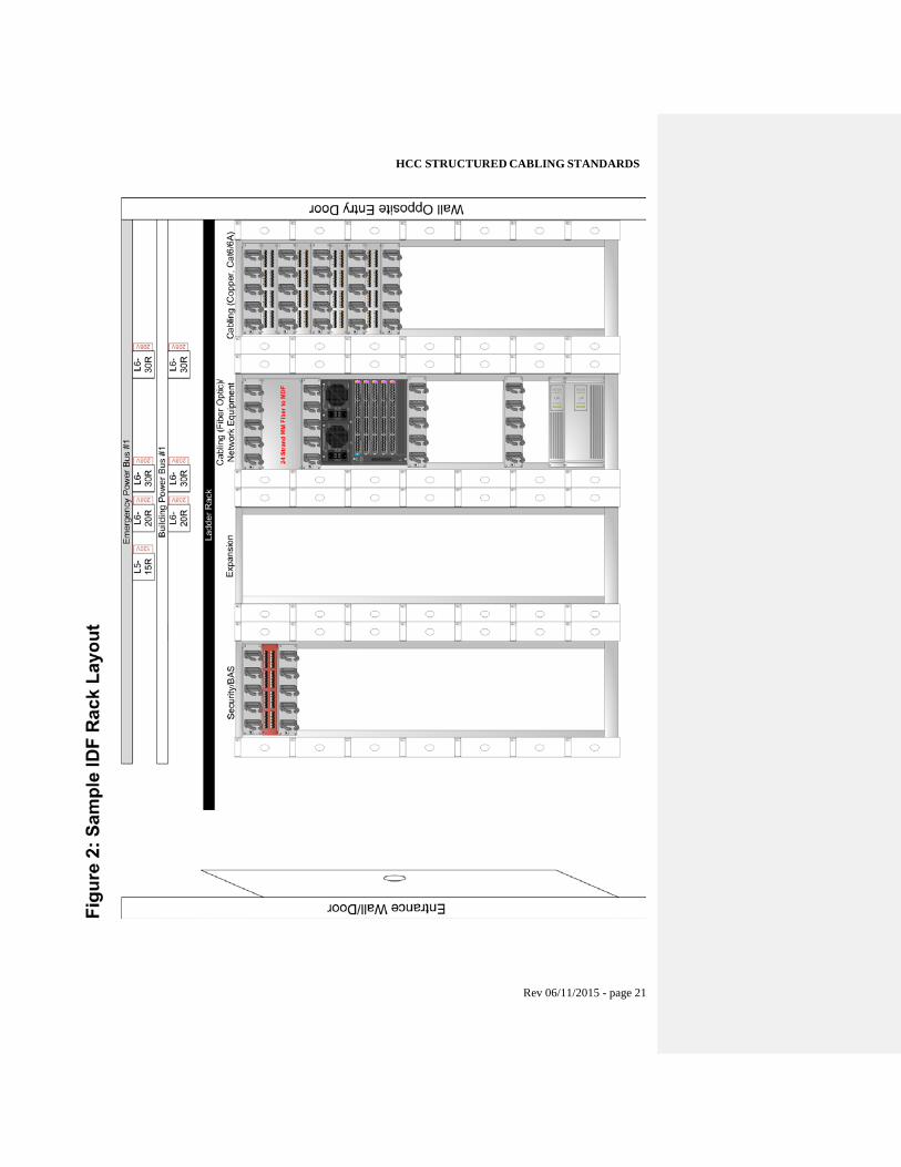
Both standard building power and emergency-generator based power feeds should be available within each respective IDF/MDF. Power circuits shall be provisioned based upon a distributed power bus system (60 AMP, 4 POLE, 'STARLINE' TRACK BUSWAY SYSTEM) with both bus bar taps mounted parallel to and above the equipment/cable racks (see figure 2). Minimum two (2) L6-30R receptacles & one (1) L6-20R taps per power feed shall be provisioned. Minimum one (1) L5-15R 120V quad receptacle power should be available in room, with preference on bus bar tap. All power requirements and quantity of circuits will be verified with HCC-IT/Networks prior to installation.
C. Uninterruptable Power Supply (UPS):
All network, voice, and server systems located within the IDF/MDF are required to be powered by HCC-IT provided Uninterruptable Power Supplies/battery back-ups. Minimum one (1) APC SAU5000RMT5U (5KVA) Smart UPS and one (1) APC AP7811 Power Distribution Unit is required per 196 Data Drops, Qty. one (1) Chassis-based switch, or Qty. four (4) stack-based switches; whichever is greater. Minimum one (1) APC AP9626 Step down transformer is required per every two (2) APC 5KVA UPS.
D. HVAC:
All IDF/MDF rooms shall be on autonomous HVAC systems, separate from the general HVAC system and cooling, with thermostats and air handlers specific to each IDF.
E. Equipment Rack Placement:
Each IDF shall have a minimum of four (4) equipment racks (per standards above). The first rack shall be mounted on the wall farthest from the entry door, and house copper patch panels. The second rack shall be reserved for the fiber patch panel (top of rack), network equipment installation (router/switches), and UPS/PDU systems at bottom of rack. The third rack will be reserved for expansion, with the fourth rack allocated for building automation and security. See figure2: for sample layout elevation.
F. Security:
All IDF/MDF rooms shall have card readers and door locks integrated into HCC’s Access Control system for restricted access.
Rev 06/11/2015 - page 19
HCC STRUCTURED CABLING STANDARDS G. Demarc Provisions
MDF rooms that are the designated demarc for the respective building/campus location should have basic provisions relative to WAN vendor and remote connectivity (i.e. AT&T, Verizon, and Level 3 Communications). These requirements shall be reviewed with HCC-IT/Networks to ensure compliance. Examples of these provisions include dedicated plywood backboards, copper grounding, fiber raceways/ladder racks, and 120V power at the fiber/equipment termination point.
4.02 WIRELESS ACCESS POINTS (AP)
A. Placement & Mounting To ensure proper placement, coverage, and density; a pre-planning site survey based upon building plans conducted by HCC-IT/Networks is required. Once locations are identified, each wireless access point (AP) is required to have a total of two Category 6A drops. Drops will be terminated into surface mount boxes with corresponding green (CAT 6A) keystone jacks, per section 2.05 A-1. Access points will be mounted on suspended ceiling grid via HCC supplied Cisco mounting brackets. Cabling vendor will coordinate installation of bracket and wireless Access Point with HCC-IT/Networks.
4.02 VOICE OVER IP (VoIP) PHONES
A. Placement & Mounting
In plan locations identifying wall phone mounts, vendor will install HCC provided Cisco IP Phone mount, product number CP-WALLMOUNTKIT. Data jack should be placed appropriately, with adequate spacing (per wall mount specifications) to accommodate mount and not interfere with BAS switches, lighting or other wall mount building devices. Wall phone locations and mounting bracket type shall be confirmed with HCC-IT/Telecom prior to installation. Current phone unit standards are listed below.
• Wall Phone CISCO CP-7821-K9= Cisco UC Phone 7821 • Desk Phone CISCO CP-8851-K9= Cisco IP Phone 8851 • Conference Room CISCO CP-8831-K9= Cisco 8831 Base/Control Panel for North America • Video Phone CISCO CP-8865-K9= Cisco IP Phone 8865, Charcoal, Camera, USB, WiFi, Expansion Port • Analog - 4 devices CISCO VG204XM Cisco VG204XM Analog Voice Gateway • Analog - 24 devices CISCO VG310 Cisco VG310 - Modular 24 FXS Port Voice over IP Gateway
Rev 06/11/2015 - page 20
HCC STRUCTURED CABLING STANDARDS
Rev 06/11/2015 - page 21