Embed Size (px)
Citation preview
8/8/2019 STS-41D Press Kit
http://slidepdf.com/reader/full/sts-41d-press-kit 1/31
NATIONAL AERONAUTICS AND SPACE ADMINISTRATION
SPACE SHUTTLE
MISSION
STS-41DPRESS KIT
AUGUST 1984
FIRST FLIGHT OF DISCOVERY
SBS-4, LEASAT-2, TELSTAR-3 DEPLOYMENT; OAST-1

8/8/2019 STS-41D Press Kit
http://slidepdf.com/reader/full/sts-41d-press-kit 2/31
STS-41D INSIGNIA
S84-26391 -- The insignia for the STS-41D mission features the Discovery, NASA's third orbital vehicle, as it makes
its maiden voyage. The ghost ship represents the orbiter's namesakes which have figured prominently in the history
of exploration. The space shuttle Discovery heads for new horizons to extend that proud tradition.
The NASA insignia design for space shuttle flights is reserved for use by the astronauts and for other official use as
the NASA Administrator may authorize. Public availability has been approved only in the form of illustrations by
the various news media. When and if there is any change in this policy, which we do not anticipate, it will be
publicly announced.
PHOTO CREDIT: NASA or National Aeronautics and Space Administration.
8/8/2019 STS-41D Press Kit
http://slidepdf.com/reader/full/sts-41d-press-kit 3/31
RELEASE NO: 84 - 11 7 Augus t 19 84
CONTACTS
Charles Redmond/Debra Rahn
Headquarters, Washington, D.C.
(Phone: 202/453-8590)
Dick Young
Kennedy Space Center, Fla.
(Phone: 305/867-2468)
Dave Alter
Johnson Space Center, Houston, Texas
(Phone: 713/483-5111)
Bob RuhlMarshall Space Flight Center, Huntsville, Ala.
(Phone: 205/453-0034)
Ralph Jackson
Dryden Flight Research Facility, Edwards, Calif.
(Phone: 805/258-8381)
8/8/2019 STS-41D Press Kit
http://slidepdf.com/reader/full/sts-41d-press-kit 4/31
RELEASE NO: 84 - 11 7 Augus t 19 84
CONTENTS
GENERAL RELEASE 5
41-D BRIEFING SCHEDULE 7
GENERAL INFORMATION 8MISSION 41-D REMANIFEST -- QUICK LOOK FACTS 9
SUMMARY OF MAJOR ACTIVITIES 10
41-D REMANIFEST SEQUENCE OF EVENTS 12
CONFIGURATION AND WEIGHTS 13
SBS-4 15
LEASAT 2 (Syncom IV-2) 16
TELSTAR 3 18
OAST-1 19
Solar Array Experiment 22
Dynamic Augmentation Experiment 23
Solar Cell Calibration Facility 23
OAST-1 Team 23
CONTINUOS FLOW ELECTROPHORESIS SYSTEM 25VEHICLE GLOW EXPERIMENT 27
CLOUDS 27
IMAX 27
SHUTTLE STUDENT INVOLVEMENT PROJECT 28
41-D FLIGHT CREW DATA 29
8/8/2019 STS-41D Press Kit
http://slidepdf.com/reader/full/sts-41d-press-kit 5/31
RELEASE NO: 84 - 11 7 Augus t 20 ,
1984
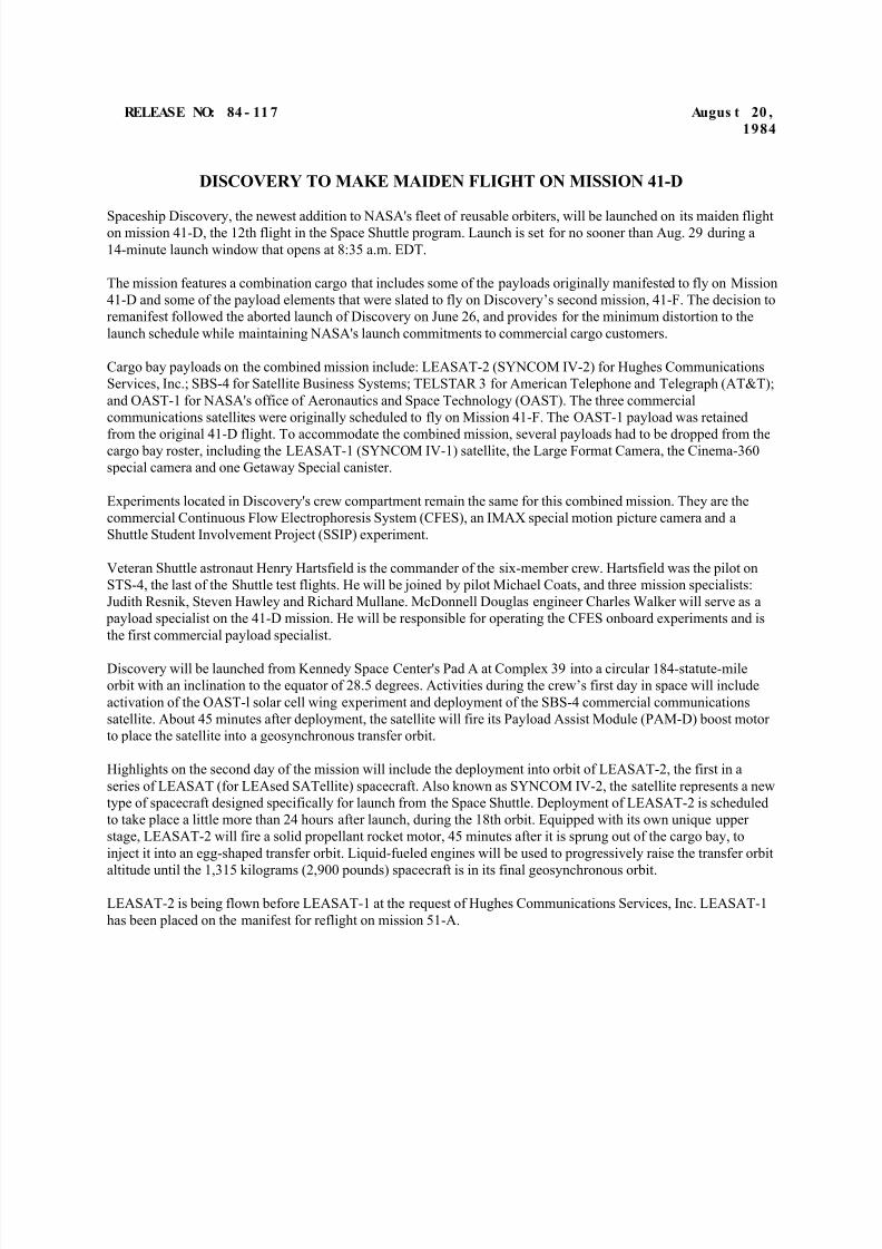
DISCOVERY TO MAKE MAIDEN FLIGHT ON MISSION 41-D
Spaceship Discovery, the newest addition to NASA's fleet of reusable orbiters, will be launched on its maiden flighton mission 41-D, the 12th flight in the Space Shuttle program. Launch is set for no sooner than Aug. 29 during a
14-minute launch window that opens at 8:35 a.m. EDT.
The mission features a combination cargo that includes some of the payloads originally manifested to fly on Mission
41-D and some of the payload elements that were slated to fly on Discovery’s second mission, 41-F. The decision to
remanifest followed the aborted launch of Discovery on June 26, and provides for the minimum distortion to the
launch schedule while maintaining NASA's launch commitments to commercial cargo customers.
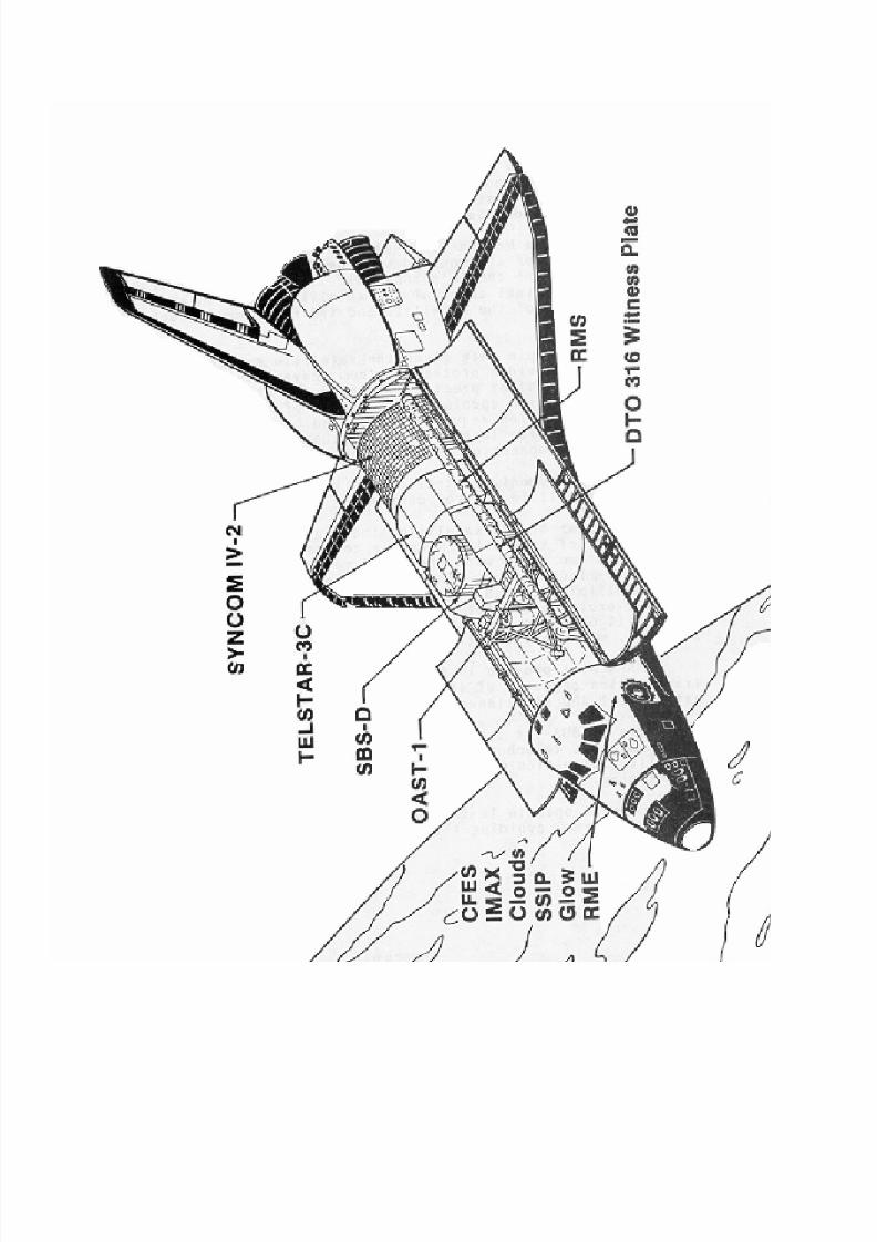
Cargo bay payloads on the combined mission include: LEASAT-2 (SYNCOM IV-2) for Hughes Communications
Services, Inc.; SBS-4 for Satellite Business Systems; TELSTAR 3 for American Telephone and Telegraph (AT&T);
and OAST-1 for NASA's office of Aeronautics and Space Technology (OAST). The three commercial
communications satellites were originally scheduled to fly on Mission 41-F. The OAST-1 payload was retained
from the original 41-D flight. To accommodate the combined mission, several payloads had to be dropped from thecargo bay roster, including the LEASAT-1 (SYNCOM IV-1) satellite, the Large Format Camera, the Cinema-360
special camera and one Getaway Special canister.
Experiments located in Discovery's crew compartment remain the same for this combined mission. They are the
commercial Continuous Flow Electrophoresis System (CFES), an IMAX special motion picture camera and a
Shuttle Student Involvement Project (SSIP) experiment.
Veteran Shuttle astronaut Henry Hartsfield is the commander of the six-member crew. Hartsfield was the pilot on
STS-4, the last of the Shuttle test flights. He will be joined by pilot Michael Coats, and three mission specialists:
Judith Resnik, Steven Hawley and Richard Mullane. McDonnell Douglas engineer Charles Walker will serve as a
payload specialist on the 41-D mission. He will be responsible for operating the CFES onboard experiments and is
the first commercial payload specialist.
Discovery will be launched from Kennedy Space Center's Pad A at Complex 39 into a circular 184-statute-mile
orbit with an inclination to the equator of 28.5 degrees. Activities during the crew’s first day in space will include
activation of the OAST-l solar cell wing experiment and deployment of the SBS-4 commercial communications
satellite. About 45 minutes after deployment, the satellite will fire its Payload Assist Module (PAM-D) boost motor
to place the satellite into a geosynchronous transfer orbit.
Highlights on the second day of the mission will include the deployment into orbit of LEASAT-2, the first in a
series of LEASAT (for LEAsed SATellite) spacecraft. Also known as SYNCOM IV-2, the satellite represents a new
type of spacecraft designed specifically for launch from the Space Shuttle. Deployment of LEASAT-2 is scheduled
to take place a little more than 24 hours after launch, during the 18th orbit. Equipped with its own unique upper
stage, LEASAT-2 will fire a solid propellant rocket motor, 45 minutes after it is sprung out of the cargo bay, to
inject it into an egg-shaped transfer orbit. Liquid-fueled engines will be used to progressively raise the transfer orbit
altitude until the 1,315 kilograms (2,900 pounds) spacecraft is in its final geosynchronous orbit.
LEASAT-2 is being flown before LEASAT-1 at the request of Hughes Communications Services, Inc. LEASAT-1
has been placed on the manifest for reflight on mission 51-A.
8/8/2019 STS-41D Press Kit
http://slidepdf.com/reader/full/sts-41d-press-kit 6/31
8/8/2019 STS-41D Press Kit
http://slidepdf.com/reader/full/sts-41d-press-kit 7/31
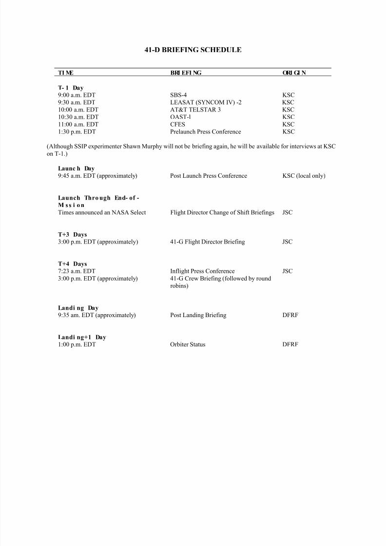
41-D BRIEFING SCHEDULE
TI ME BRI EFI NG ORI GI N
T- 1 Day
9:00 a.m. EDT SBS-4 KSC9:30 a.m. EDT LEASAT (SYNCOM IV) -2 KSC
10:00 a.m. EDT AT&T TELSTAR 3 KSC
10:30 a.m. EDT OAST-l KSC
11:00 a.m. EDT CFES KSC
1:30 p.m. EDT Prelaunch Press Conference KSC
(Although SSIP experimenter Shawn Murphy will not be briefing again, he will be available for interviews at KSC
on T-1.)
Launc h Day
9:45 a.m. EDT (approximately) Post Launch Press Conference KSC (local only)
Launch Thro ugh End- of -
Mi s s i o n
Times announced an NASA Select Flight Director Change of Shift Briefings JSC
T+3 Days
3:00 p.m. EDT (approximately) 41-G Flight Director Briefing JSC
T+4 Days
7:23 a.m. EDT Inflight Press Conference JSC
3:00 p.m. EDT (approximately) 41-G Crew Briefing (followed by round
robins)
Landi ng Day
9:35 am. EDT (approximately) Post Landing Briefing DFRF
Landi ng+1 Day
1:00 p.m. EDT Orbiter Status DFRF
8/8/2019 STS-41D Press Kit
http://slidepdf.com/reader/full/sts-41d-press-kit 8/31
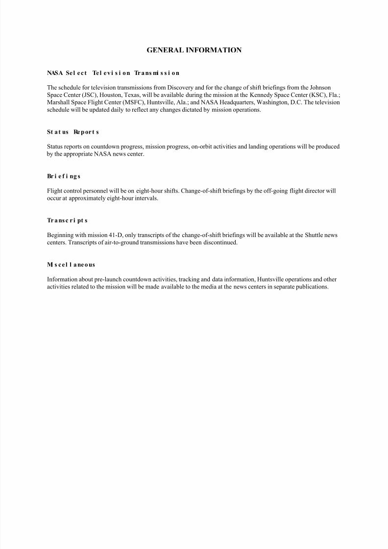
GENERAL INFORMATION
NASA Se l ec t Te l ev i s i on Trans mi s s i on
The schedule for television transmissions from Discovery and for the change of shift briefings from the Johnson
Space Center (JSC), Houston, Texas, will be available during the mission at the Kennedy Space Center (KSC), Fla.;Marshall Space Flight Center (MSFC), Huntsville, Ala.; and NASA Headquarters, Washington, D.C. The television
schedule will be updated daily to reflect any changes dictated by mission operations.
St at us Report s
Status reports on countdown progress, mission progress, on-orbit activities and landing operations will be produced
by the appropriate NASA news center.
Br i e f i ng s
Flight control personnel will be on eight-hour shifts. Change-of-shift briefings by the off-going flight director willoccur at approximately eight-hour intervals.
Tr a ns c r i pt s
Beginning with mission 41-D, only transcripts of the change-of-shift briefings will be available at the Shuttle news
centers. Transcripts of air-to-ground transmissions have been discontinued.
Mi s ce l l aneous
Information about pre-launch countdown activities, tracking and data information, Huntsville operations and other
activities related to the mission will be made available to the media at the news centers in separate publications.
8/8/2019 STS-41D Press Kit
http://slidepdf.com/reader/full/sts-41d-press-kit 9/31
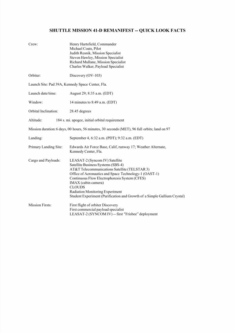
SHUTTLE MISSION 41-D REMANIFEST -- QUICK LOOK FACTS
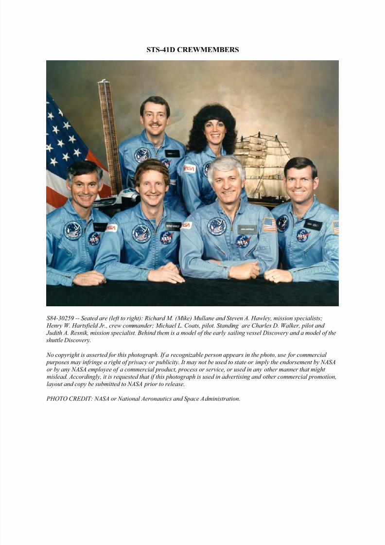
Crew: Henry Hartsfield, Commander
Michael Coats, Pilot
Judith Resnik, Mission Specialist
Steven Hawley, Mission SpecialistRichard Mullane, Mission Specialist
Charles Walker, Payload Specialist
Orbiter: Discovery (OV-103)
Launch Site: Pad 39A, Kennedy Space Center, Fla.
Launch date/time: August 29; 8:35 a.m. (EDT)
Window: 14 minutes to 8:49 a.m. (EDT)
Orbital Inclination: 28.45 degrees
Altitude: 184 s. mi. apogee, initial orbital requirement
Mission duration: 6 days, 00 hours, 56 minutes, 30 seconds (MET), 96 full orbits; land on 97
Landing: September 4, 6:32 a.m. (PDT); 9:32 a.m. (EDT)
Primary Landing Site: Edwards Air Force Base, Calif, runway 17; Weather Alternate,
Kennedy Center, Fla.
Cargo and Payloads: LEASAT-2 (Syncom IV) Satellite
Satellite Business Systems (SBS-4)
AT&T Telecommunications Satellite (TELSTAR 3)
Office of Aeronautics and Space Technology-1 (OAST-1)Continuous Flow Electrophoresis System (CFES)
IMAX (cabin camera)
CLOUDS
Radiation Monitoring Experiment
Student Experiment (Purification and Growth of a Simple Gallium Crystal)
Mission Firsts: First flight of orbiter Discovery
First commercial payload specialist
LEASAT-2 (SYNCOM IV) -- first "Frisbee” deployment
8/8/2019 STS-41D Press Kit
http://slidepdf.com/reader/full/sts-41d-press-kit 10/31
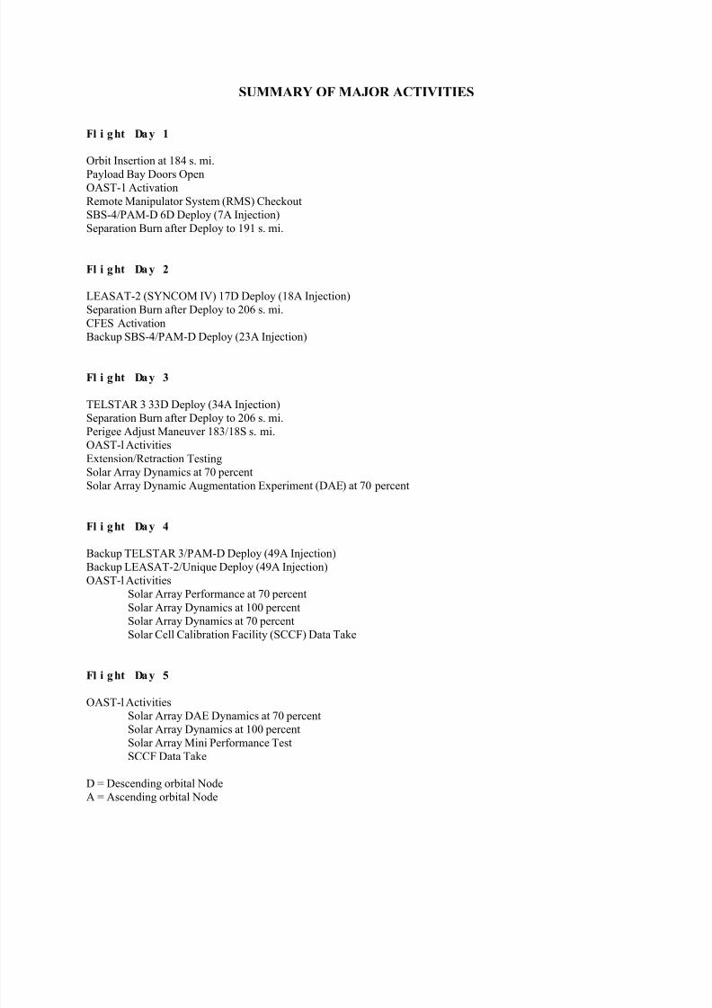
SUMMARY OF MAJOR ACTIVITIES
Fl i ght Day 1
Orbit Insertion at 184 s. mi.
Payload Bay Doors OpenOAST-1 Activation
Remote Manipulator System (RMS) Checkout
SBS-4/PAM-D 6D Deploy (7A Injection)
Separation Burn after Deploy to 191 s. mi.
Fl i ght Day 2
LEASAT-2 (SYNCOM IV) 17D Deploy (18A Injection)
Separation Burn after Deploy to 206 s. mi.
CFES Activation
Backup SBS-4/PAM-D Deploy (23A Injection)
Fl i ght Day 3
TELSTAR 3 33D Deploy (34A Injection)
Separation Burn after Deploy to 206 s. mi.
Perigee Adjust Maneuver 183/18S s. mi.
OAST-l Activities
Extension/Retraction Testing
Solar Array Dynamics at 70 percent
Solar Array Dynamic Augmentation Experiment (DAE) at 70 percent
Fl i ght Day 4
Backup TELSTAR 3/PAM-D Deploy (49A Injection)
Backup LEASAT-2/Unique Deploy (49A Injection)
OAST-l Activities
Solar Array Performance at 70 percent
Solar Array Dynamics at 100 percent
Solar Array Dynamics at 70 percent
Solar Cell Calibration Facility (SCCF) Data Take
Fl i ght Day 5
OAST-l ActivitiesSolar Array DAE Dynamics at 70 percent
Solar Array Dynamics at 100 percent
Solar Array Mini Performance Test
SCCF Data Take
D = Descending orbital Node
A = Ascending orbital Node
8/8/2019 STS-41D Press Kit
http://slidepdf.com/reader/full/sts-41d-press-kit 11/31
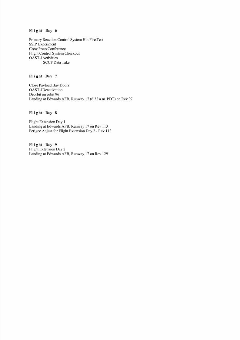
Fl i ght Day 6
Primary Reaction Control System Hot Fire Test
SSIP Experiment
Crew Press Conference
Flight Control System Checkout
OAST-l ActivitiesSCCF Data Take
Fl i ght Day 7
Close Payload Bay Doors
OAST-l Deactivation
Deorbit on orbit 96
Landing at Edwards AFB, Runway 17 (6:32 a.m. PDT) on Rev 97
Fl i ght Day 8
Flight Extension Day 1
Landing at Edwards AFB, Runway 17 on Rev 113
Perigee Adjust for Flight Extension Day 2 - Rev 112
Fl i ght Day 9
Flight Extension Day 2
Landing at Edwards AFB, Runway 17 on Rev 129
8/8/2019 STS-41D Press Kit
http://slidepdf.com/reader/full/sts-41d-press-kit 12/31
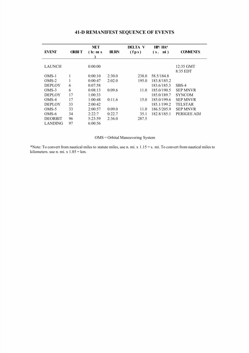
41-D REMANIFEST SEQUENCE OF EVENTS
EVENT ORBI T
MET
( h: m: s
)
BURN
DELTA V
( f p s )
HP/ HA*
( s . mi ) COMMENTS
LAUNCH 0:00:00 12:35 GMT
8:35 EDT
OMS-1 1 0:00:10 2:30.0 238.0 58.5/184.8
OMS-2 1 0:00:47 2:02.0 195.0 183.8/185.2
DEPLOY 6 0:07:58 183.6/185.3 SBS-4
OMS-3 6 0:08:13 0:09.6 11.0 185.0/190.5 SEP MNVR
DEPLOY 17 1:00:33 185.0/189.7 SYNCOM
OMS-4 17 1:00:48 0:11.6 15.0 185.0/199.6 SEP MNVR
DEPLOY 33 2:00:42 185.1/199.2 TELSTAR
OMS-5 33 2:00:57 0:09.0 11.0 186.5/205.9 SEP MNVR
OMS-6 34 2:22:7 0:22.7 35.1 182.8/185.1 PERIGEE ADJ
DEORBIT 96 5:23:59 2:36.0 287.5
LANDING 97 6:00:56
OMS = Orbital Maneuvering System
*Note: To convert from nautical miles to statute miles, use n. mi. x 1.15 = s. mi. To convert from nautical miles to
kilometers. use n. mi. x 1.85 = km.
8/8/2019 STS-41D Press Kit
http://slidepdf.com/reader/full/sts-41d-press-kit 13/31
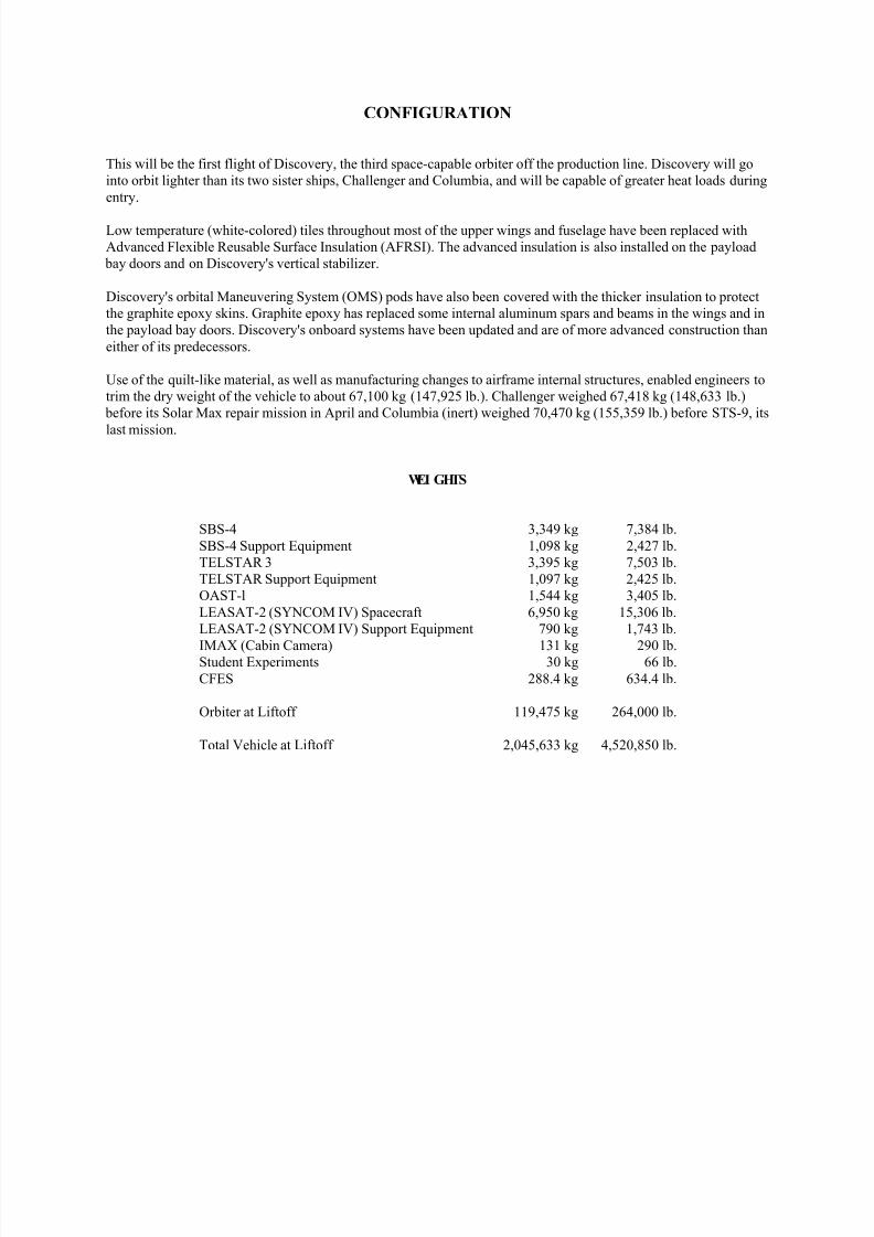
CONFIGURATION
This will be the first flight of Discovery, the third space-capable orbiter off the production line. Discovery will go
into orbit lighter than its two sister ships, Challenger and Columbia, and will be capable of greater heat loads during
entry.
Low temperature (white-colored) tiles throughout most of the upper wings and fuselage have been replaced with
Advanced Flexible Reusable Surface Insulation (AFRSI). The advanced insulation is also installed on the payload
bay doors and on Discovery's vertical stabilizer.
Discovery's orbital Maneuvering System (OMS) pods have also been covered with the thicker insulation to protect
the graphite epoxy skins. Graphite epoxy has replaced some internal aluminum spars and beams in the wings and in
the payload bay doors. Discovery's onboard systems have been updated and are of more advanced construction than
either of its predecessors.
Use of the quilt-like material, as well as manufacturing changes to airframe internal structures, enabled engineers to
trim the dry weight of the vehicle to about 67,100 kg (147,925 lb.). Challenger weighed 67,418 kg (148,633 lb.)
before its Solar Max repair mission in April and Columbia (inert) weighed 70,470 kg (155,359 lb.) before STS-9, its
last mission.
WEI GHTS
SBS-4 3,349 kg 7,384 lb.
SBS-4 Support Equipment 1,098 kg 2,427 lb.
TELSTAR 3 3,395 kg 7,503 lb.
TELSTAR Support Equipment 1,097 kg 2,425 lb.
OAST-l 1,544 kg 3,405 lb.
LEASAT-2 (SYNCOM IV) Spacecraft 6,950 kg 15,306 lb.
LEASAT-2 (SYNCOM IV) Support Equipment 790 kg 1,743 lb.
IMAX (Cabin Camera) 131 kg 290 lb.Student Experiments 30 kg 66 lb.
CFES 288.4 kg 634.4 lb.
Orbiter at Liftoff 119,475 kg 264,000 lb.
Total Vehicle at Liftoff 2,045,633 kg 4,520,850 lb.
8/8/2019 STS-41D Press Kit
http://slidepdf.com/reader/full/sts-41d-press-kit 14/31
8/8/2019 STS-41D Press Kit
http://slidepdf.com/reader/full/sts-41d-press-kit 15/31
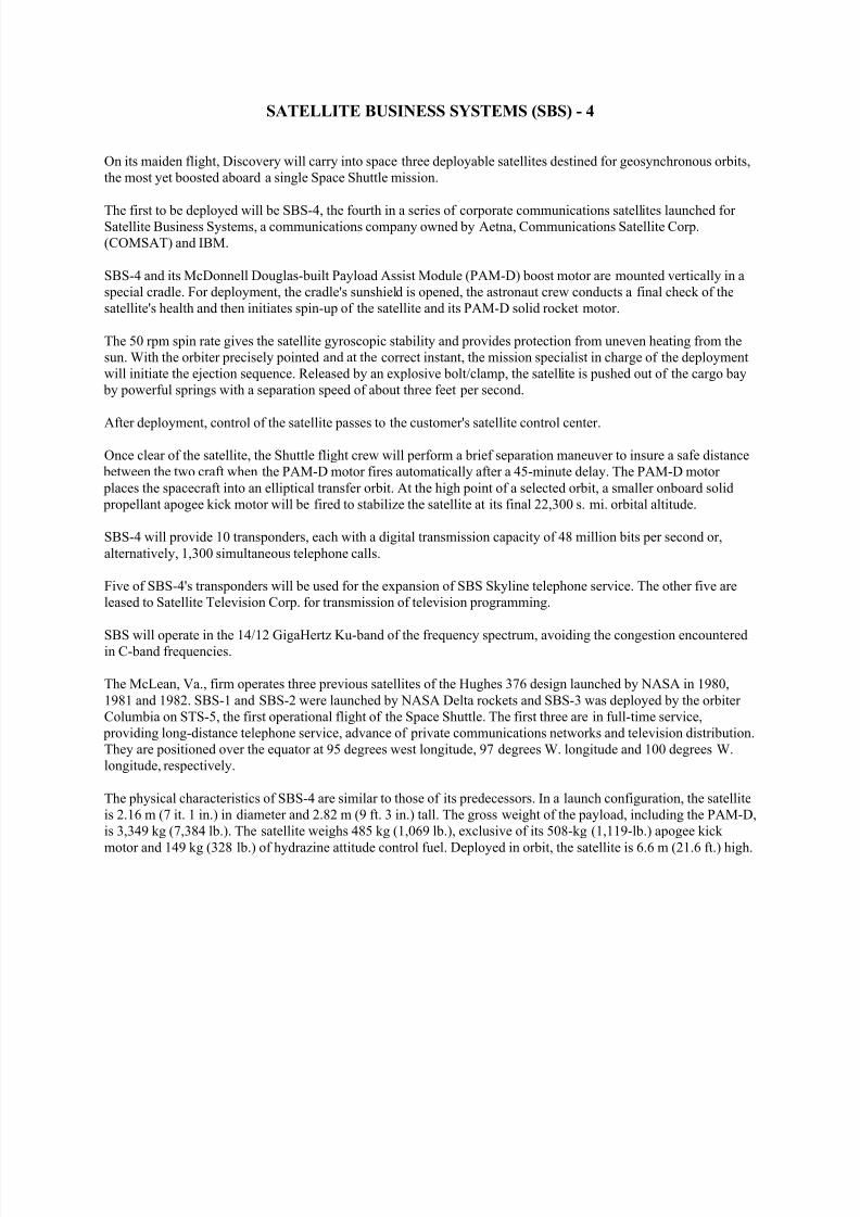
SATELLITE BUSINESS SYSTEMS (SBS) - 4
On its maiden flight, Discovery will carry into space three deployable satellites destined for geosynchronous orbits,
the most yet boosted aboard a single Space Shuttle mission.
The first to be deployed will be SBS-4, the fourth in a series of corporate communications satellites launched for Satellite Business Systems, a communications company owned by Aetna, Communications Satellite Corp.
(COMSAT) and IBM.
SBS-4 and its McDonnell Douglas-built Payload Assist Module (PAM-D) boost motor are mounted vertically in a
special cradle. For deployment, the cradle's sunshield is opened, the astronaut crew conducts a final check of the
satellite's health and then initiates spin-up of the satellite and its PAM-D solid rocket motor.
The 50 rpm spin rate gives the satellite gyroscopic stability and provides protection from uneven heating from the
sun. With the orbiter precisely pointed and at the correct instant, the mission specialist in charge of the deployment
will initiate the ejection sequence. Released by an explosive bolt/clamp, the satellite is pushed out of the cargo bay
by powerful springs with a separation speed of about three feet per second.
After deployment, control of the satellite passes to the customer's satellite control center.
Once clear of the satellite, the Shuttle flight crew will perform a brief separation maneuver to insure a safe distance
between the two craft when the PAM-D motor fires automatically after a 45-minute delay. The PAM-D motor
places the spacecraft into an elliptical transfer orbit. At the high point of a selected orbit, a smaller onboard solid
propellant apogee kick motor will be fired to stabilize the satellite at its final 22,300 s. mi. orbital altitude.
SBS-4 will provide 10 transponders, each with a digital transmission capacity of 48 million bits per second or,
alternatively, 1,300 simultaneous telephone calls.
Five of SBS-4's transponders will be used for the expansion of SBS Skyline telephone service. The other five are
leased to Satellite Television Corp. for transmission of television programming.
SBS will operate in the 14/12 GigaHertz Ku-band of the frequency spectrum, avoiding the congestion encounteredin C-band frequencies.
The McLean, Va., firm operates three previous satellites of the Hughes 376 design launched by NASA in 1980,
1981 and 1982. SBS-1 and SBS-2 were launched by NASA Delta rockets and SBS-3 was deployed by the orbiter
Columbia on STS-5, the first operational flight of the Space Shuttle. The first three are in full-time service,
providing long-distance telephone service, advance of private communications networks and television distribution.
They are positioned over the equator at 95 degrees west longitude, 97 degrees W. longitude and 100 degrees W.
longitude, respectively.
The physical characteristics of SBS-4 are similar to those of its predecessors. In a launch configuration, the satellite
is 2.16 m (7 it. 1 in.) in diameter and 2.82 m (9 ft. 3 in.) tall. The gross weight of the payload, including the PAM-D,
is 3,349 kg (7,384 lb.). The satellite weighs 485 kg (1,069 lb.), exclusive of its 508-kg (1,119-lb.) apogee kick
motor and 149 kg (328 lb.) of hydrazine attitude control fuel. Deployed in orbit, the satellite is 6.6 m (21.6 ft.) high.
8/8/2019 STS-41D Press Kit
http://slidepdf.com/reader/full/sts-41d-press-kit 16/31
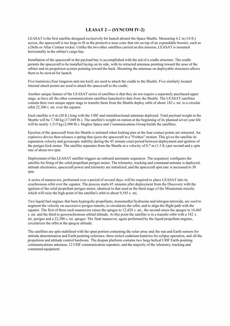
LEASAT 2 -- (SYNCOM IV-2)
LEASAT is the first satellite designed exclusively for launch aboard the Space Shuttle. Measuring 4.2 m (14 ft.)
across, the spacecraft is too large to fit in the protective nose cone that sits on top of an expendable booster, such as
a Delta or Atlas Centaur rocket. Unlike the two other satellites carried on this mission, LEASAT is mounted
horizontally in the orbiter's cargo bay.
Installation of the spacecraft in the payload bay is accomplished with the aid of a cradle structure. The cradle
permits the spacecraft to be installed laying on its side, with its retracted antennas pointing toward the nose of the
orbiter and its propulsion system pointing toward the back. Mounting the antennas on deployable structures allows
them to be stowed for launch.
Five trunnions (four longeron and one keel) are used to attach the cradle to the Shuttle. Five similarly located
internal attach points are used to attach the spacecraft to the cradle.
Another unique feature of the LEASAT series of satellites is that they do not require a separately purchased upper
stage, as have all the other communications satellites launched to date from the Shuttle. The LEASAT satellites
contain their own unique upper stage to transfer them from the Shuttle deploy orbit of about 182 s. mi. to a circular
orbit 22,300 s. mi. over the equator.
Each satellite is 6 m (20 ft.) long with the UHF and omnidirectional antennas deployed. Total payload weight in theShuttle will be 7,740 kg (17,049 lb.). The satellite's weight on station at the beginning of its planned seven year life
will be nearly 1,315 kg (2,900 lb.). Hughes Space and Communications Group builds the satellites.
Ejection of the spacecraft from the Shuttle is initiated when locking pins at the four contact points are retracted. An
explosive device then releases a spring that ejects the spacecraft in a "Frisbee" motion. This gives the satellite its
separation velocity and gyroscopic stability during the 45 minute coast period between deployment and ignition of
the perigee kick motor. The satellite separates from the Shuttle at a velocity of 0.7 m (1.5 ft.) per second and a spin
rate of about two rpm.
Deployment of the LEASAT satellite triggers an onboard automatic sequencer. The sequencer configures the
satellite for firing of the solid propellant perigee motor. The telemetry, tracking and command antenna is deployed,
attitude electronics, spacecraft power and telemetry are initialized, and the spacecraft spin rate is increased to 30
rpm.
A series of maneuvers, performed over a period of several days, will be required to place LEASAT into its
synchronous orbit over the equator. The process starts 45 minutes after deployment from the Discovery with the
ignition of the solid propellant perigee motor, identical to that used as the third stage of the Minuteman missile,
which will raise the high point of the satellite's orbit to about 9,545 s. mi.
Two liquid fuel engines that burn hypergolic propellants, monomethyl hydrazine and nitrogen tetroxide, are used to
augment the velocity on successive perigee transits, to circularize the orbit, and to align the flight path with the
equator. The first of three such maneuvers raises the apogee to 12,420 s. mi., the second raises the apogee to 16,445
s. mi. and the third to geosynchronous orbital altitude. At this point the satellite is in a transfer orbit with a 182 s.
mi. perigee and a 22,300 s. mi. apogee. The final maneuver, again performed by the liquid propellant engines,
circularizes the orbit at the apogee altitude.
The satellites are spin-stabilized with the spun portion containing the solar array and the sun and Earth sensors for
attitude determination and Earth pointing reference, three nickel-cadmium batteries for eclipse operation, and all the
propulsion and attitude control hardware. The despun platform contains two large helical UHF Earth-pointing
communications antennas, 12 UHF communication repeaters, and the majority of the telemetry, tracking and
command equipment.

8/8/2019 STS-41D Press Kit
http://slidepdf.com/reader/full/sts-41d-press-kit 17/31
Hughes Communications Services, Inc., will operate the worldwide LEASAT satellite communications system
under a contract with the Department of Defense, with the U.S. Navy acting as the executive agent. The system will
include five LEASAT satellites, one of which will be a spare, and the associated ground facilities. Users will
include mobile air, surface, subsurface and fixed Earth stations of the Navy, Marine Corps, Air Force and Army.
The satellites will occupy geostationary positions south of the United States and over the Atlantic, Pacific and
Indian oceans .
8/8/2019 STS-41D Press Kit
http://slidepdf.com/reader/full/sts-41d-press-kit 18/31
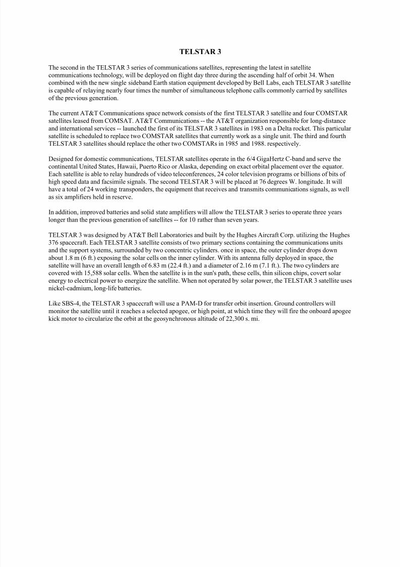
TELSTAR 3
The second in the TELSTAR 3 series of communications satellites, representing the latest in satellite
communications technology, will be deployed on flight day three during the ascending half of orbit 34. When
combined with the new single sideband Earth station equipment developed by Bell Labs, each TELSTAR 3 satellite
is capable of relaying nearly four times the number of simultaneous telephone calls commonly carried by satellites
of the previous generation.
The current AT&T Communications space network consists of the first TELSTAR 3 satellite and four COMSTAR
satellites leased from COMSAT. AT&T Communications -- the AT&T organization responsible for long-distance
and international services -- launched the first of its TELSTAR 3 satellites in 1983 on a Delta rocket. This particular
satellite is scheduled to replace two COMSTAR satellites that currently work as a single unit. The third and fourth
TELSTAR 3 satellites should replace the other two COMSTARs in 1985 and 1988. respectively.
Designed for domestic communications, TELSTAR satellites operate in the 6/4 GigaHertz C-band and serve the
continental United States, Hawaii, Puerto Rico or Alaska, depending on exact orbital placement over the equator.
Each satellite is able to relay hundreds of video teleconferences, 24 color television programs or billions of bits of
high speed data and facsimile signals. The second TELSTAR 3 will be placed at 76 degrees W. longitude. It will
have a total of 24 working transponders, the equipment that receives and transmits communications signals, as well
as six amplifiers held in reserve.
In addition, improved batteries and solid state amplifiers will allow the TELSTAR 3 series to operate three years
longer than the previous generation of satellites -- for 10 rather than seven years.
TELSTAR 3 was designed by AT&T Bell Laboratories and built by the Hughes Aircraft Corp. utilizing the Hughes
376 spacecraft. Each TELSTAR 3 satellite consists of two primary sections containing the communications units
and the support systems, surrounded by two concentric cylinders. once in space, the outer cylinder drops down
about 1.8 m (6 ft.) exposing the solar cells on the inner cylinder. With its antenna fully deployed in space, the
satellite will have an overall length of 6.83 m (22.4 ft.) and a diameter of 2.16 m (7.1 ft.). The two cylinders are
covered with 15,588 solar cells. When the satellite is in the sun's path, these cells, thin silicon chips, covert solar
energy to electrical power to energize the satellite. When not operated by solar power, the TELSTAR 3 satellite uses
nickel-cadmium, long-life batteries.
Like SBS-4, the TELSTAR 3 spacecraft will use a PAM-D for transfer orbit insertion. Ground controllers will
monitor the satellite until it reaches a selected apogee, or high point, at which time they will fire the onboard apogee
kick motor to circularize the orbit at the geosynchronous altitude of 22,300 s. mi.
8/8/2019 STS-41D Press Kit
http://slidepdf.com/reader/full/sts-41d-press-kit 19/31
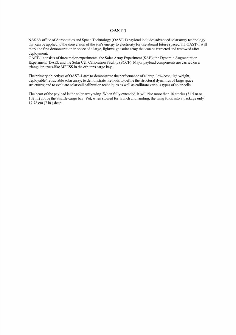
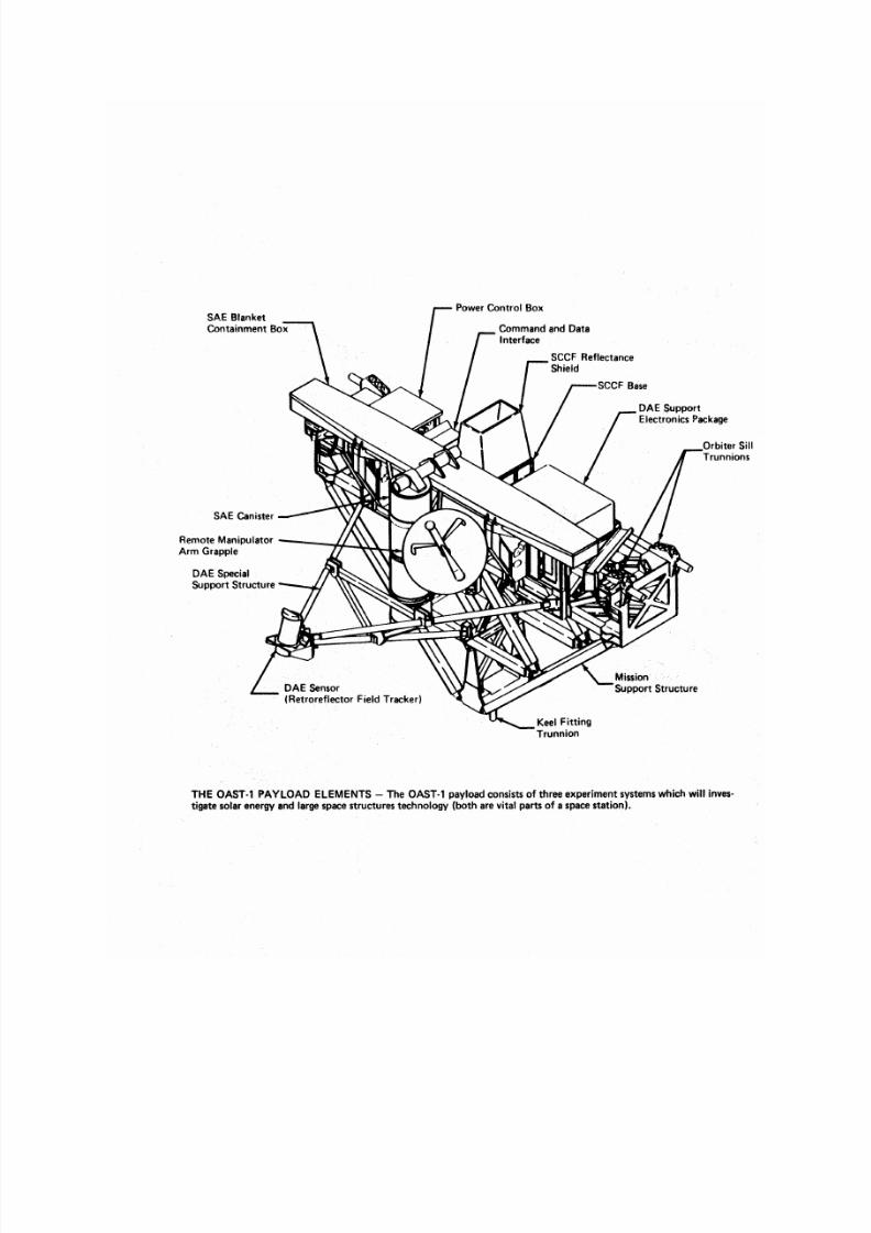
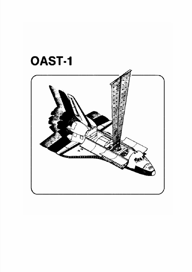
OAST-1
NASA's office of Aeronautics and Space Technology (OAST-1) payload includes advanced solar array technology
that can be applied to the conversion of the sun's energy to electricity for use aboard future spacecraft. OAST-1 will
mark the first demonstration in space of a large, lightweight solar array that can be retracted and restowed after
deployment.
OAST-1 consists of three major experiments: the Solar Array Experiment (SAE); the Dynamic AugmentationExperiment (DAE); and the Solar Cell Calibration Facility (SCCF). Major payload components are carried on a
triangular, truss-like MPESS in the orbiter's cargo bay.
The primary objectives of OAST-1 are: to demonstrate the performance of a large, low-cost, lightweight,
deployable/ retractable solar array; to demonstrate methods to define the structural dynamics of large space
structures; and to evaluate solar cell calibration techniques as well as calibrate various types of solar cells.
The heart of the payload is the solar array wing. When fully extended, it will rise more than 10 stories (31.5 m or
102 ft.) above the Shuttle cargo bay. Yet, when stowed for launch and landing, the wing folds into a package only
17.78 cm (7 in.) deep.
8/8/2019 STS-41D Press Kit
http://slidepdf.com/reader/full/sts-41d-press-kit 20/31
8/8/2019 STS-41D Press Kit
http://slidepdf.com/reader/full/sts-41d-press-kit 21/31
8/8/2019 STS-41D Press Kit
http://slidepdf.com/reader/full/sts-41d-press-kit 22/31
During the mission, the array will be deployed and retracted several times, and data will be gathered on how the
system performs. The deployed wing will also be vibrated by controlled firings of the orbiter's vernier reaction
control system thrusters. Movements of the wing will be sensed and recorded for post-flight analysis. Additionally,
a facility for calibrating solar cells will be operated.
OAST-l will be operated from the aft flight deck of the orbiter by the Shuttle crew. Payload operations will be
controlled from the Mission Control Center at the Johnson Space Center. An OAST-1 mission management teamwill support these operations from the Customer Support Room in Mission Control, and teams of engineers and
investigators will provide technical support from the Marshall Space Flight Center's Huntsville Operations Support
Center (HOSE). This group will receive and monitor mission data in real-time and will advise the mission team at
Johns on .
Sol ar Arr ay Experi ment
The solar array is 31.5 m (102 ft.) tall by 4 m (13 ft.) wide. Its primary structure is a thin blanket of plastic material
called Kapton. The blanket consists of 84 panels that fold accordion-style when the structure is retracted.
The solar array blanket is deployed by extending an epoxyfiberglass mast, stored in a 43 cm (17-in.) diameter, 1.5 m
(5 ft.) tall canister. The mast consists of three continuous longerons, about 0.63 cm (1/4 in.) in diameter,interconnected by three battens at intervals of 23 cm (9 in.). The result is a structure with a triangular cross section
that is longitudinally stabilized by short guy wires between batten attachments. Rollers are located on the outside of
all three longerons at the intersections with the battens.
To extend the mast, a "nut" with internal threads rotates at the top of the canister. As it rotates, the rollers move up
through the threads of the nut, allowing the longerons to straighten and the guy wires to hold the structure in a rigid
form. Rotation of the nut in the opposite direction drives the rollers back into the canister, retracting the mast and
coiling it back into the canister.
The initial few inches of mast extension unlatches the containment box lid holding the array blanket. As the mast is
extended, it unfolds the blanket. When the blanket is 70 percent deployed, a tension bar is also deployed that applies
about 66.7 Newtons of pull (about 15 lb.) in the direction of the containment box. This assures that the section of
blanket deployed up to that point will be pulled flat.
Another tension bar at the bottom of the blanket applies another 22.7 Newtons (5 lb.) of pull to flatten the last 30
percent of the blanket when the array is fully extended. Structural dynamics tests will be conducted with the solar
array at both 70 percent and 100 percent of its fully deployed height.
The mast is extended and retracted at about 4 cm (1.5 in.) per second. It takes about 14 minutes to fully extend the
wing. When the wing is retracted, small springs at the panel hinges "remind" the blanket of which direction to
collapse as it refolds.
The mast canister and solar array containment box are mounted on the side of the MPESS by bracketry. Also
mounted on this bracketry is a tape recorder and other support electronics. Accelerometers mounted to the cover of
the containment box provide data on the movement of the top of the structure. Additional data will be gathered by
television cameras located in the cargo bay. These cameras will be used to observe mechanical motions of the
blanket panels as they are deployed and restowed. other sensors will monitor the thermal environment of the
structure and the solar cells mounted near the top of the blanket. Data from accelerometers and thermal sensors, and
the electrical performance of the solar cells on the wing, will be stored on the recorder.
8/8/2019 STS-41D Press Kit
http://slidepdf.com/reader/full/sts-41d-press-kit 23/31

8/8/2019 STS-41D Press Kit
http://slidepdf.com/reader/full/sts-41d-press-kit 24/31
The development of photogrammetric techniques used to acquire structural dynamics data and the post flight
analysis of that data will be managed by the Langley Research Center in Hampton, Va. The SCCF experiment
development and data analysis activity will be managed by the Jet Propulsion Laboratory. These activities are also
being conducted on behalf of the office of Aeronautics and Space Technology.
Investigators for SAE and DAE include: L.E. Young, principal investigator, MSFC; R.W. Schock, co-investigator,
DAE structural dynamics, MSFC; M.L. Brumfield, co-investigator, photogrammetry-structural dynamics, LaRC;and SCCF, R.G. Downing, principal investigator, JPL.
8/8/2019 STS-41D Press Kit
http://slidepdf.com/reader/full/sts-41d-press-kit 25/31
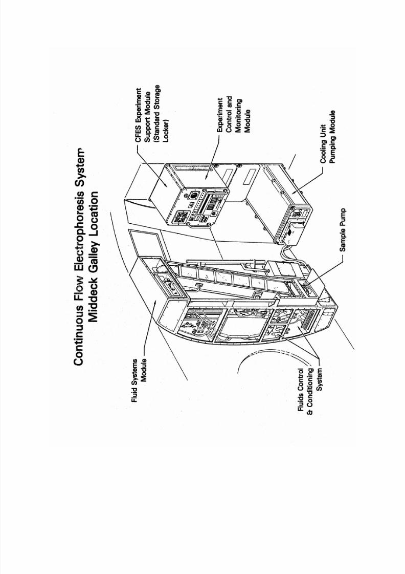
CONTINUOUS FLOW ELECTROPHORESIS SYSTEM
McDonnell Douglas engineer Charles D. Walker will become the first non-astronaut to fly into space under a
NASA policy that allows major Space Shuttle customers to have one of their own people onboard to operate their
payloads. Payload specialists will most often be scientists or engineers with special skills to operate a scientific
experiment or to run a unique and critical processing system.
Walker's job will be to operate the CFES, which is a modified version of the device that has been flown on four
previous Shuttle missions. His presence is needed because the device has been changed significantly to operate
continuously for about 100 hours during the mission. Instead of processing several small samples, the CFES will
collect one large sample on this mission.
The large quantities of material processed will be furnished to Ortho Pharmaceutical Corp., Raritan, N.J., for
clinical testing. McDonnell Douglas has an agreement with Ortho Pharmaceutical Corp. to study jointly the
commercial feasibility of using space-based processing to manufacture pharmaceuticals. McDonnell Douglas will
separate material in increasing quantities so that Ortho will be able to conduct research and clinical testing needed to
gain Food and Drug Administration approval for a new pharmaceutical product. Both companies hope this new
product will be ready for the commercial market by the late 1980s.
The CFES is a device that separates materials in solution by subjecting them to an electrical field. In this process, acontinuous stream of biological material is injected into a buffer solution flowing through a thin, rectangular
chamber. When the electrical field is applied, the biological materials pull apart into separate streams. These streams
flow out of the top of the chamber and are collected.
The CFES is mounted on the middeck of the Discovery. The system weighs about 288.4 kg (634.4 lb.). The orbiter
supplies the necessary power to the unit and access to a cooling system to dissipate the heat generated by the
process.
8/8/2019 STS-41D Press Kit
http://slidepdf.com/reader/full/sts-41d-press-kit 26/31
8/8/2019 STS-41D Press Kit
http://slidepdf.com/reader/full/sts-41d-press-kit 27/31
VEHICLE GLOW EXPERIMENT
A flight experiment to characterize surface-originated vehicle glow will be conducted during flight 41-D.
observations made during recent Shuttle flights (STS flights 3-8) indicate that optical emissions originate on
spacecraft surfaces facing the direction of orbital motion. Material specimens flown on STS-8 have shown spectral
distribution and intensity of the glow to be different for different materials, and that the intensity becomes stronger
as spacecraft altitude is reduced. These results are of principal concern to mission scientists for the Space Telescopeand for the astronomical observatories that will be aboard the Space Station, because slight orbit degradations will
cause the glow to become more intense and possibly interfere with faint star-light measurements for attitudes where
the telescope optics are oriented toward the "windward" direction.
Nine strips of material, representing different spacecraft materials, have been attached circumferentially to the
orbiter's robot arm. The flight crew will take pictures of the strips from the orbiter's aft flight deck during two night
passes late in the mission. Prior to each photographic opportunity, the attitude of the orbiter will be adjusted to
produce direct impingement of the orbital environment onto the material strips.
One set of photographs will be obtained at an orbital altitude of 199 s. mi. and a second set at 139 s. mi. to evaluate
the intensity of glow at these altitudes. To enhance the brightness level and reduce the exposure time, an image
intensifier will be used with the camera system. Spectral information of the glow region above each material will be
documented using a spectrometer assembly uniquely designed for this experiment.
CLOUDS
The Clouds payload consists of two, 250-exposure camera assemblies with battery-powered motor drives, l05 mm
F/2 lenses and infrared filters. All of the hardware will be stowed in a middeck locker and will be used at the aft
flight deck station for cloud photography data collection.
IMAX
Located in the middeck will be an IMAX motion picture camera, making the second of three scheduled trips into
space aboard the Shuttle. Footage from the Shuttle flights will be assembled into a film called "The Dream IsAlive." The IMAX high-fidelity motion picture system uses a large 70 mm film frame that, because of its size,
improves picture quality. IMAX films are displayed on a screen that is nine times larger than a conventional screen,
producing a more compelling effect.
Fifteen IMAX theaters are now operating around the world and 13 are under construction. IMAX Systems Corp. is
producing the film, which is expected to premiere at the National Air and Space Museum in Washington, D.C., in
early summer 1985. About a month after it premieres in Washington, the film will be shown at the new IMAX
theater at Kennedy Space Center's Visitors' Center.
The IMAX camera is part of a joint project among NASA, the National Air and Space Museum, IMAX Systems
Corp. of Toronto, Canada, and the Lockheed Corp.

8/8/2019 STS-41D Press Kit
http://slidepdf.com/reader/full/sts-41d-press-kit 28/31
SHUTTLE STUDENT INVOLVEMENT PROJECT
There is one experiment chosen for mission 41-D from the Shuttle Student Involvement Project. This experiment
was proposed by Shawn P. Murphy from Newburg, Ohio. It is sponsored by Rockwell International. The
experiment is designed to compare a crystal grown by the "Float Zone" technique in a low gravity environment with
one grown in an identical manner on Earth.
The material consists of a 25-cm (10-in.) rod of gallium impregnated with thallium. Heat is applied to the crystal
interface until a molten zone is formed, and the zone then moves up the length of the rod. In the absence of gravity,
a more uniform distribution of the thallium and a more perfect gallium crystal is expected to result. The experiment
is contained in the middeck.
8/8/2019 STS-41D Press Kit
http://slidepdf.com/reader/full/sts-41d-press-kit 29/31
8/8/2019 STS-41D Press Kit
http://slidepdf.com/reader/full/sts-41d-press-kit 30/31
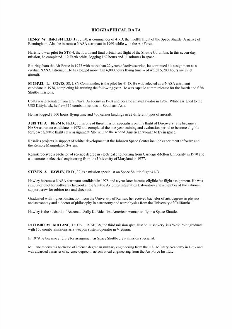
BIOGRAPHICAL DATA
HENRY W. HARTSFI ELD Jr . , 50, is commander of 41-D, the twelfth flight of the Space Shuttle. A native of
Birmingham, Ala., he became a NASA astronaut in 1969 while with the Air Force.
Hartsfield was pilot for STS-4, the fourth and final orbital test flight of the Shuttle Columbia. In this seven-day
mission, he completed 112 Earth orbits, logging 169 hours and 11 minutes in space.
Retiring from the Air Force in 1977 with more than 22 years of active service, he continued his assignment as a
civilian NASA astronaut. He has logged more than 6,000 hours flying time -- of which 5,200 hours are in jet
aircraft.
MI CHAEL L. COATS, 38, USN Commander, is the pilot for 41-D. He was selected as a NASA astronaut
candidate in 1978, completing his training the following year. He was capsule communicator for the fourth and fifth
Shuttle missions.
Coats was graduated from U.S. Naval Academy in 1968 and became a naval aviator in 1969. While assigned to the
USS Kittyhawk, he flew 315 combat missions in Southeast Asia.
He has logged 3,500 hours flying time and 400 carrier landings in 22 different types of aircraft.
JUDI TH A. RESNI K , Ph.D., 35, is one of three mission specialists on this flight of Discovery. She became a
NASA astronaut candidate in 1978 and completed the one-year training and evaluation period to become eligible
for Space Shuttle flight crew assignment. She will be the second American woman to fly in space.
Resnik's projects in support of orbiter development at the Johnson Space Center include experiment software and
the Remote Manipulator System.
Resnik received a bachelor of science degree in electrical engineering from Carnegie-Mellon University in 1970 and
a doctorate in electrical engineering from the University of Maryland in 1977.
STEVEN A. HAWLEY, Ph.D., 32, is a mission specialist on Space Shuttle flight 41-D.
Hawley became a NASA astronaut candidate in 1978 and a year later became eligible for flight assignment. He was
simulator pilot for software checkout at the Shuttle Avionics Integration Laboratory and a member of the astronaut
support crew for orbiter test and checkout.
Graduated with highest distinction from the University of Kansas, he received bachelor of arts degrees in physics
and astronomy and a doctor of philosophy in astronomy and astrophysics from the University of California.
Hawley is the husband of Astronaut Sally K. Ride, first American woman to fly in a Space Shuttle.
RI CHARD M. MULLANE, Lt. Col., USAF, 38, the third mission specialist on Discovery, is a West Point graduate
with 150 combat missions as a weapon system operator in Vietnam.
In 1979 he became eligible for assignment as Space Shuttle crew mission specialist.
Mullane received a bachelor of science degree in military engineering from the U.S. Military Academy in 1967 and
was awarded a master of science degree in aeronautical engineering from the Air Force Institute.

8/8/2019 STS-41D Press Kit
http://slidepdf.com/reader/full/sts-41d-press-kit 31/31
CHARLES D. WALKER , 36, is the first commercial payload specialist assigned by NASA to a Space Shuttle flight
crew.
Walker is chief test engineer for the McDonnell Douglas Electrophoresis operations in Space project. As payload
specialist, Walker will operate the materials processing equipment, a project aimed at separating large quantities of
biological materials in space for ultimate use in new pharmaceuticals.
Walker was graduated from Purdue University in 1971 with a bachelor of science degree in aeronautical and
astronautical engineering.
Prior to joining McDonnell Douglas, Walker was project engineer responsible for computer-based manufacturing
process controls and design of ordnance production equipment at the Naval Sea Systems Command Engineering
Center, Crane, Ind.