Embed Size (px)
Citation preview
Studies on High Alumina Blast Furnace Slags
Amitabh Shankar
Doctoral Thesis
School of Industrial Engineering and Management
Department of Material Science and Engineering
Royal Institute of Technology
SE-100 44 Stockholm
Sweden 2007
Akademisk avhandling som med tillstånd av Kungliga Tekniska Högskolan i Stockholm,
framlägges för offentlig granskning för avläggande av Teknologie doktorsexamen,
fredagen den 15 Juni 2007, kl. 10:00 i sal B1 Brinellvägen 23, KTH, Stockholm
ISRN KTH/MSE--07/38--SE+THMETU/AVH
ISBN 978-91-7178-710-1

This work is dedicated to my Parents.
ABSTRACT
In the present work, viscosities and sulphide capacities of high alumina blast
furnace slags were investigated. The systems investigated were four component CaO-
SiO2-MgO-Al2O3 quaternary system, CaO-SiO2-MgO-Al2O3-TiO2 and CaO-SiO2-MgO-
Al2O3-CaF2 quinary systems.
Viscosities of high alumina blast furnace slags were experimentally determined
by the rotating cylinder method using Brookfield digital viscometer model LVDV-II+
pro. Experiments were conducted in the temperature range of 1573- 1873 K. The effects
of temperature, basicity, TiO2, CaF2 and silica activity of slags on viscosity were studied.
Viscosity decreases with basicity for high alumina blast furnace slags with increase in
basicity and CaF2. At higher basicity (~0.8), slag viscosity decreases even with small
amount of TiO2 (~2%) addition in the slag. With increase in silica activity in the range of
0.1 to 0.4,viscosity of slag increases and the increase is steeper below liquidus
temperature.
Sulphide capacity of the slag was measured using gas-slag equlibria. The liquid
slag was equilibrated with Ar-CO-CO2-SO2 gas mixture. The slag systems studied were
the same as in the case of viscosity measurements. Experiments were conducted in the
temperature range of 1773 to 1873 K. Effect of temperature, basicity, MgO,TiO2 and
CaF2 contents of slags on sulphide capacity were studied. As expected, sulphide capacity
was found to increase with increase in temperature and basicity. At higher experimental
temperature (~ 1873 K) TiO2 was found to decrease the sulphide capacity of slags. But, at
lower temperature, there was no significant effect of TiO2 on the sulphide capacity.
Sulphide capacity increases with increase in MgO content of slag if MgO content is more
than 5%.
Based on above experimental data, models were developed for estimation of
viscosity and sulphide capacity of blast furnace slags. These models were later on applied
for designing the slags for achieving the optimum slag characteristics so that slag volume
can be reduced. With the help of these models slag volume was reduced to the extent of
5-10 kg per ton hot metal and also silicon content of the hot metal was reduced by around
10% with some improvement in slag viscosity and sulphide capacity of the slag.
ACKNOWLEDGEMENTS
First, and most of all, I would like to thank my supervisor Professor Seshadri
Seetharaman for his excellent guidance, support and sincere help throughout the various
stages of his research work.
I would also like to thank my co supervisor Professor A. K. Lahiri for his excellent
guidance, support and encouragement through out this work. Special thanks for his help
in analyzing the results.
I am also grateful to Dr. Mårten Görnerup for helping me in setting up the experimental
facility to start up the work.
I take this opportunity to thank Dr. Sanjay Chandra and Mr. R. V. Ramna, TATA
STEEL, for their valuable discussion in analyzing the results and help for implementing
the results in the plant.
I am also thankful to Dr. Debashish Bhattacharjee, TATA STEEL, for his constant
support and encouragement during his research work.
I also take this opportunity to thank my colleagues in the Department of Material Science
and Engineering especially Peter Kling for helping me in the experimental work.
Financial help from TATA STEEL, India is gratefully acknowledged.
Last, I would like to thank my wife Rupa Shankar, brothers Pramod Shankar and Binod
Shankar for their encouragement and support during this work.
Amitabh Shankar
June 2007, Stockholm, Sweden
SUPPLEMENTS
The present thesis is based on following papers:
Supplement 1: “Experimental investigation of viscosities in CaO-SiO2-MgO-Al2O3 and
CaO-SiO2-MgO-Al2O3 -TiO2 slags”: A. Shankar, Mårten Görnerup, A.
K. Lahiri, S. Seetharaman.
Submitted for publication in Metallurical and Materials Transaction
B, 2007.
Supplement 2: “Estimation of viscosities of high alumina blast furnace slags”: A.
Shankar , Mårten Görnerup, A. K. Lahiri, S. Seetharaman.
Accepted in Ironmaking & Steelmaking 2007
Supplement 3: “Sulphur partition between hot metal and high alumina blast furnace
slag”: A. Shankar.
Ironmaking & Steelmaking, Vol. 33, No. 5, 2006, pp. 413-418.
Supplement 4: “Sulphide capacity of high alumina blast furnace slags”:Amitabh
Shankar, Mårten Görnerup, A. K. Lahiri, S. Seetharaman.
Metallurical and Materials Transaction B, Vol. 37B, No.6, 2006,
pp.941-947.
The author’s contribution to the different supplement of this thesis:
Supplement 1: Literature Survey, experimental work, thermodynamic calculation and
major part of writing.
Approximate contribution: 80%
Supplement 2: Literature Survey, experimental work, modeling work and major part of
writing.
Approximate contribution: 75%
Supplement 3: Literature Survey, data collection, thermodynamic calculation and
complete writing.
Approximate contribution: 100%
Supplement 4: Literature Survey, experimental work, thermodynamic calculation and
major part of writing.
Approximate contribution: 70%.
Parts of the work were presented in the following conferences:
I: “Viscosity and Sulphide capacity of high alumina blast furnace slags”: A. Shankar,
Mårten Görnerup, A. K. Lahiri, S. Seetharaman.
Ishii Symposium, Sydney, Australia March 2006
II. “Property measurements of Slags and Fluxes towards slag design in blast furnace,
BOF and continuous casting”: A. Shankar, S. Basu, A. K. Lahiri, S.
Seetharaman.
Accepted for presentation in International conference on Advances in
Metallurgical Processes and Materials to be held in Dnipropetrovsk, Ukraine,
during May 27 – 30, 2007.
CONTENTS
1. INTRODUCTION 1
2. VISCOSITY OF BLAST FURNACE SLAGS 2
2.1 Viscosity of slags –a fundamental consideration 2
2.2 Relevance of present work on viscosities
in Ironmaking 3
2.3 Available Viscosity models in the literature 4
2.4 Experimental determination of viscosity 9
2.4.1 Apparatus for viscosity measurement 9
2.4.2 Materials and preparation of samples 11
2.4.3 Procedure for viscosity measurement 12
2.4.4 Sample analysis 13
2.5 Results and discussion 14
3. SULPHIDE CAPACITY OF BLAST FURNACE SLAGS 20
3.1 Thermodynamics of desulphurisation 20
3.1.1 General aspects 20
3.1.2 Gas –slag distribution equilibria 20
3.1.3 Slag-metal distribution equilibria 21
3.2 Relevance of present work on sulphide
capacities in Ironmaking process 22
3.3 Available Sulphide capacity models in the literature 23
3.4 Present work 24
3.4.1 Materials 24
3.4.2 Experimental Procedure 24
3.5 Results and discussion 28
4. PLANT TRIALS 35
5. SUMMARY AND CONCLUSIONS 40
6. FUTURE WORK 41
7. REFERENCES 42
1
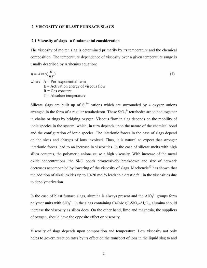
1. INTRODUCTION
Blast furnace slag composition has very important bearing on its physicochemical
characteristics which affects the degree of desulphurisation, smoothness of operation,
slag handling, coke consumption, hot metal productivity and its quality etc. The slag
properties which affect most are viscosity, sulphide capacity, alkali capacity and liquidus
temperature. These properties have great influence on the overall blast furnace process.
Variation of these slag characteristics with composition and temperature has, therefore,
been a field of active research from 1960’s to 1980’s1-5. Most of these studies were
carried out over low alumina blast furnace slags with alumina normally less than 15 pct.
as found in literature6-12. Low alumina slags generally have low viscosity, high sulphide
capacity, and low liquidus temperature as well as lower slag volume than high alumina
slag with alumina normally more than 15 pct. High alumina slag is encountered mainly
with Indian blast furnaces because of high alumina/silica ratio in iron ore as well as sinter
and high ash content in coke. These slags are highly viscous. Thus, there is a wide scope
for studying the physicochemical properties of high alumina slags so as to improve
performance of the blast furnace in terms of slag volume and thereby, furnace
productivity.
In the present work, viscosity and sulphide capacity of high alumina slags have been
investigated for CaO-SiO2-MgO-Al2O3,CaO-SiO2-MgO-Al2O3-TiO2, and CaO-SiO2-
MgO-Al2O3- CaF2 systems. Viscosity was measured by the rotating cylinder method
using Brookfield digital viscometer. Sulphide capacity was determined by gas–slag
equilibration technique. The objective of the present work was to create a database for
viscosities and sulphide capacities of high alumina blast furnace slags so that the blast
furnace slags can be designed for optimum blast furnace performance.
2
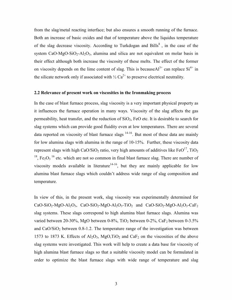
2. VISCOSITY OF BLAST FURNACE SLAGS
2.1 Viscosity of slags –a fundamental consideration
The viscosity of molten slag is determined primarily by its temperature and the chemical
composition. The temperature dependence of viscosity over a given temperature range is
usually described by Arrhenius equation:
)exp(RT
EA=η (1)
where A = Pre- exponential term
E = Activation energy of viscous flow
R = Gas constant
T = Absolute temperature
Silicate slags are built up of Si4+ cations which are surrounded by 4 oxygen anions
arranged in the form of a regular tetrahederon. These SiO44- tetrahedra are joined together
in chains or rings by bridging oxygen. Viscous flow in slag depends on the mobility of
ionic species in the system, which, in turn depends upon the nature of the chemical bond
and the configuration of ionic species. The interionic forces in the case of slags depend
on the sizes and charges of ions involved. Thus, it is natural to expect that stronger
interionic forces lead to an increase in viscosities. In the case of silicate melts with high
silica contents, the polymeric anions cause a high viscosity. With increase of the metal
oxide concentrations, the Si-O bonds progressively breakdown and size of network
decreases accompanied by lowering of the viscosity of slags. Mackenzie13 has shown that
the addition of alkali oxides up to 10-20 mol% leads to a drastic fall in the viscosities due
to depolymerization.
In the case of blast furnace slags, alumina is always present and the AlO45- groups form
polymer units with SiO44-. In the slags containing CaO-MgO-SiO2-Al2O3, alumina should
increase the viscosity as silica does. On the other hand, lime and magnesia, the suppliers
of oxygen, should have the opposite effect on viscosity.
Viscosity of slags depends upon composition and temperature. Low viscosity not only
helps to govern reaction rates by its effect on the transport of ions in the liquid slag to and
3
from the slag/metal reacting interface; but also ensures a smooth running of the furnace.
Both an increase of basic oxides and that of temperature above the liquidus temperature
of the slag decrease viscosity. According to Turkdogan and Bills8 , in the case of the
system CaO-MgO-SiO2-Al2O3, alumina and silica are not equivalent on molar basis in
their effect although both increase the viscosity of these melts. The effect of the former
on viscosity depends on the lime content of slag. This is becauseAl3+ can replace Si
4+ in
the silicate network only if associated with ½ Ca2+ to preserve electrical neutrality.
2.2 Relevance of present work on viscosities in the Ironmaking process
In the case of blast furnace process, slag viscosity is a very important physical property as
it influences the furnace operation in many ways. Viscosity of the slag affects the gas
permeability, heat transfer, and the reduction of SiO2, FeO etc. It is desirable to search for
slag systems which can provide good fluidity even at low temperatures. There are several
data reported on viscosity of blast furnace slags 14-16
. But most of these data are mainly
for low alumina slags with alumina in the range of 10-15%. Further, these viscosity data
represent slags with high CaO/SiO2 ratio, very high amounts of additives like FeO17, TiO2
18, Fe2O3
16 etc. which are not so common in final blast furnace slag. There are number of
viscosity models available in literature14-16
, but they are mainly applicable for low
alumina blast furnace slags which couldn’t address wide range of slag composition and
temperature.
In view of this, in the present work, slag viscosity was experimentally determined for
CaO-SiO2-MgO-Al2O3, CaO-SiO2-MgO-Al2O3-TiO2 and CaO-SiO2-MgO-Al2O3-CaF2
slag systems. These slags correspond to high alumina blast furnace slags. Alumina was
varied between 20-30%, MgO between 0-8%, TiO2 between 0-2%, CaF2 between 0-3.5%
and CaO/SiO2 between 0.8-1.2. The temperature range of the investigation was between
1573 to 1873 K. Effects of Al2O3, MgO,TiO2 and CaF2 on the viscosities of the above
slag systems were investigated. This work will help to create a data base for viscosity of
high alumina blast furnace slags so that a suitable viscosity model can be formulated in
order to optimize the blast furnace slags with wide range of temperature and slag
4
chemistry. This in turn will help to design the slag which could lead in reducing the slag
rate and hence increase in the blast furnace productivity.
2.3 Available Viscosity models in the literature
There are number of models available in the literature for estimation of viscosity. Out of
these models, some of the models which are most relevant to blast furnace slags have
been discussed below.
Iida Model
In general, molten slags have random network structure; the viscosity is the property
which is very sensitive to their structure. Thus, the models for a viscosity prediction must
take the structure into account. Iida’s model14 is based upon relating the structure to
parameters representing the basicity of the slag and is expressed as
)exp(*
i
OB
EAµµ = (2)
where E and A are function of temperature, µo is a function of molar volume, melting point and chemical composition and Bi
* is function of chemical composition
TTA27
10000.710962.1745.1 3 −×+−= ×− (3)
TE 1065.311.113−−= × (4)
X ii∑= µµ
00
(5)
where µ0
is the viscosity of non network forming (hypothetical) melts.
])(/exp[)(
)/exp())([108.1 3/2
2/1
7
0
.
TRHV
RTHTM
mim
im ii
ii
i
−×=µ (6)
)(1.52/1
TH m ii= (7)
where M is the formula weight , Vm the molar volume at the melting point Tm, R gas
constant, , X the mole fraction and the subscript i refers to the component. The model is
5
connected with the modified basiicty index Bi
* , which can readily calculated using the
relationship
∑
∑
++
+
=
WWW
WWB
TiOTiOOAlOAlii
OFeOFeii
iA
B
223232
**
*
)(
)(32
*
32
ααα
αα (8)
where α and W are the specific coefficients and the mass percentage, and the subscripts
A and B represent acidic and basic oxides respectively. The value ofα i and µ i0 are
given in Table I. α i is the modified specific coefficient indicating the interaction of the
amphoteric oxide with other components in slags, and would be given as function of
basicity index Bi
19 and the mass percentage of the amphoteric oxide Wi. Thus the
modified basicity index Bi
*can be obtained by taking account of characteristic features of
amphoteric oxides: the value of α*
iwill widely vary with slag composition. A correlation
between α*
i and slag composition can be established based on known slag viscosity and
this has been shown for α*
32OAlas follows:
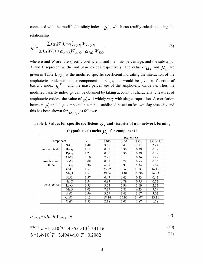
Table I: Values for specific coefficient α i and viscosity of non network forming
(hypothetical) melts µi0 for component i
µOi/ mPa.s
Component
αi 1400 1450 1500 1530/ oC
SiO2 1.48 3.76 3.43 3.11 2.92
B2O3 1.12 0.31 0.30 0.29 0.29
Acidic Oxide
P2O5 1.23 0.30 0.30 0.29 0.28
Al2O3 0.10 7.95 7.12 6.36 5.89
Fe2O3 0.08 0.81 0.78 0.75 0.73
Amphoteric
Oxide TiO2 0.36 6.59 5.93 5.34 5.02
CaO 1.53 23.82 20.67 17.83 16.15
MgO 1.51 39.66 34.01 28.96 26.03
K2O 1.37 0.47 0.45 0.43 0.42
Na2O 1.94 0.83 0.79 0.75 0.72
Li2O 3.55 3.24 2.96 2.69 2.52
MnO 1.03 7.35 6.81 6.23 5.79
FeO 0.96 3.59 3.43 3.07 3.02
Cr2O3 0.13 18.14 15.92 14.07 13.11
Basic Oxide
CaF2 1.53 2.18 2.02 1.87 1.78
cbWaB OAlOAl i++=
3232
*
α (9)
where 16.41103552.4102.1225
+−= ××−−TTa (10)
2062.0104944.3104.1427
+−= ××−−
TTb (11)
6
16.22105568.21000.8226
−+= ××−−−
TTc (12)
Hence, using equation (2) to (9) slag viscosity can be estimated for CaO-SiO2-MgO-
Al2O3, CaO-SiO2-MgO-Al2O3-TiO2, and CaO-SiO2-MgO-Al2O3- CaF2 slag systems.
NPL model
Mills and Sridhar 16 proposed following viscosity model based on Arrhenius equation:
T
BA += lnlnη (13)
The parameters B and lnA were expressed in terms of corrected optical basicity as
follows:
Λ− +=
CORR
B 88.277.1
1000ln (14)
17.14432.357)(69.232ln2
−ΛΛ− +=CORRCORR
A (15)
The corrected optical basicity, ΛCORR
can be derived from the charge balance and the
compositions of the slag studied20
∑∑ ΛΛΛ
Λ++
++=
nxnxnx
nxnxnxCORR
3
'
32
'
21
'
1
33
'
322
'
211
'
1 (16)
where xi
' and ni are the corrected mole fraction and the number of oxygen in the oxide
of component i. Λiis the optical basicity of ith oxide.
Ray’s model
Ray and Pal17 developed a simple, novel method which allows the estimation of
viscosity on the basis of melt composition and optical basicity. They used Weymann-
Frenkel equation for viscosity calculation and this was expressed as follows:
7
T
BA
T
1000lnln +=
η (17)
where A and B are linearly related, similar to Urbain’s equation and B was quadratic
expression of optical basicity. Equations for expressing A and B are shown below:
492.122056.0ln +=− BA (18)
22.19669.46614.2972
+Λ−Λ=B (19)
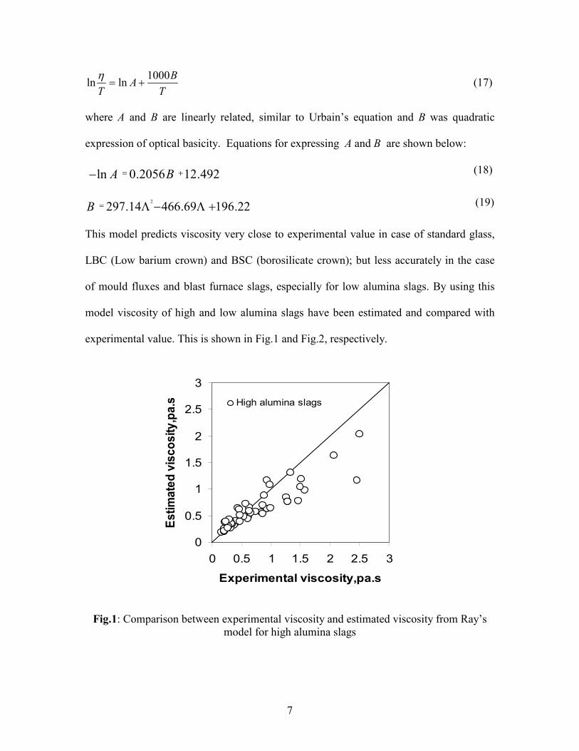
This model predicts viscosity very close to experimental value in case of standard glass,
LBC (Low barium crown) and BSC (borosilicate crown); but less accurately in the case
of mould fluxes and blast furnace slags, especially for low alumina slags. By using this
model viscosity of high and low alumina slags have been estimated and compared with
experimental value. This is shown in Fig.1 and Fig.2, respectively.
0
0.5
1
1.5
2
2.5
3
0 0.5 1 1.5 2 2.5 3
Experimental viscosity,pa.s
Estimated viscosity,pa.s High alumina slags
Fig.1: Comparison between experimental viscosity and estimated viscosity from Ray’s
model for high alumina slags
8
0
0.5
1
1.5
2
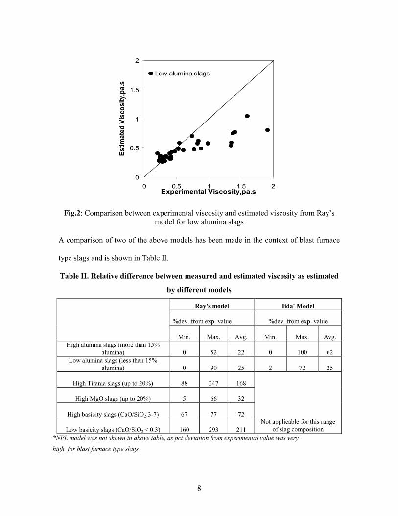
0 0.5 1 1.5 2Experimental Viscosity,pa.s
Estimated Viscosity,pa.s
Low alumina slags
Fig.2: Comparison between experimental viscosity and estimated viscosity from Ray’s
model for low alumina slags
A comparison of two of the above models has been made in the context of blast furnace
type slags and is shown in Table II.
Table II. Relative difference between measured and estimated viscosity as estimated
by different models
Ray's model Iida' Model
%dev. from exp. value
%dev. from exp. value
Min.
Max.
Avg. Min.
Max.
Avg.
High alumina slags (more than 15%
alumina) 0
52 22 0
100
62
Low alumina slags (less than 15%
alumina) 0
90 25 2
72 25
High Titania slags (up to 20%) 88
247 168
High MgO slags (up to 20%) 5
66 32
High basicity slags (CaO/SiO2:3-7) 67
77 72
Low basicity slags (CaO/SiO2 < 0.3) 160
293 211
Not applicable for this range
of slag composition
*NPL model was not shown in above table, as pct deviation from experimental value was very
high for blast furnace type slags
9
From this table it is clear that error associated with above models is very high compared
to the experimental error. Therefore, it was required to develop a viscosity model, which
could be applicable for wide range of slag composition and temperature.
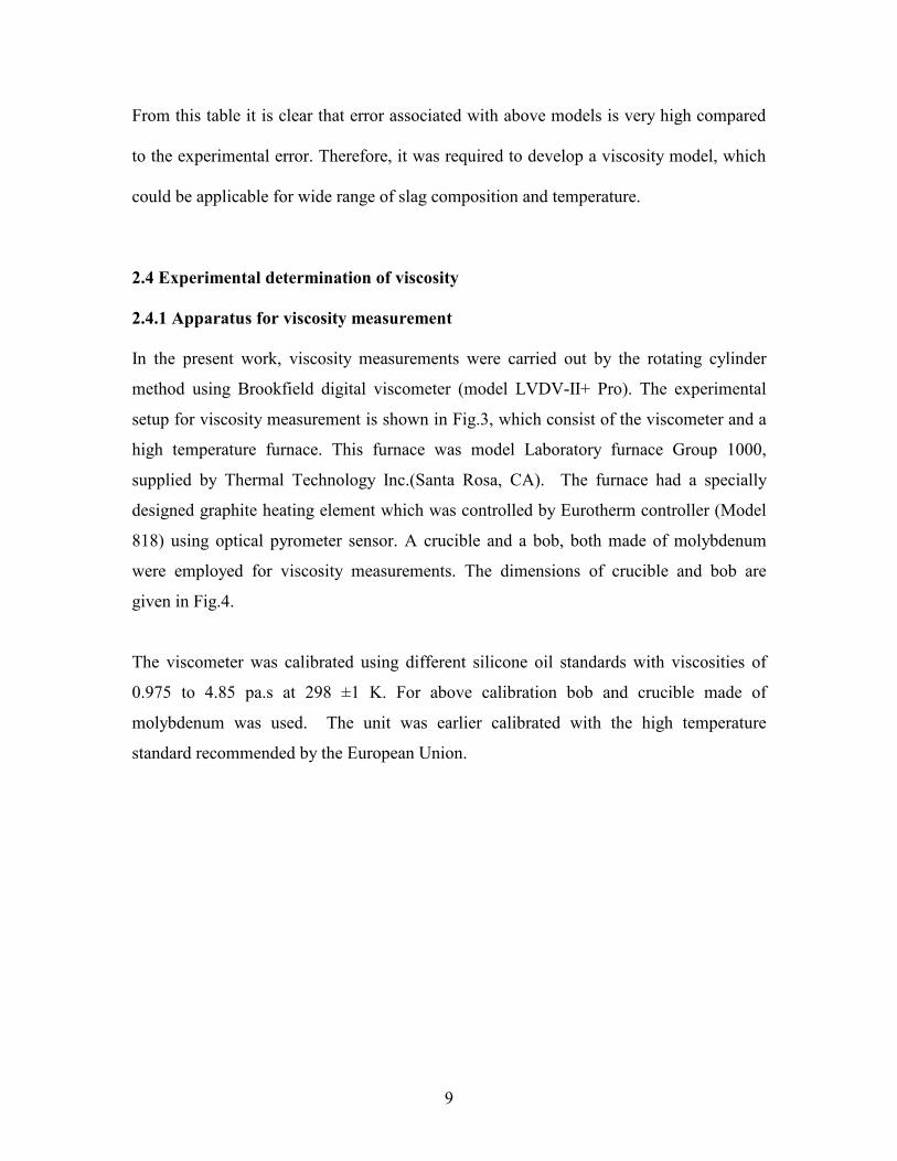
2.4 Experimental determination of viscosity
2.4.1 Apparatus for viscosity measurement
In the present work, viscosity measurements were carried out by the rotating cylinder
method using Brookfield digital viscometer (model LVDV-II+ Pro). The experimental
setup for viscosity measurement is shown in Fig.3, which consist of the viscometer and a
high temperature furnace. This furnace was model Laboratory furnace Group 1000,
supplied by Thermal Technology Inc.(Santa Rosa, CA). The furnace had a specially
designed graphite heating element which was controlled by Eurotherm controller (Model
818) using optical pyrometer sensor. A crucible and a bob, both made of molybdenum
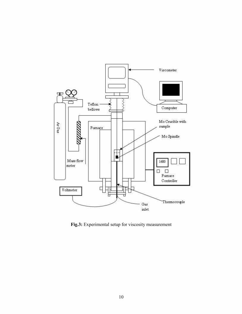
were employed for viscosity measurements. The dimensions of crucible and bob are
given in Fig.4.
The viscometer was calibrated using different silicone oil standards with viscosities of
0.975 to 4.85 pa.s at 298 ±1 K. For above calibration bob and crucible made of
molybdenum was used. The unit was earlier calibrated with the high temperature
standard recommended by the European Union.
10
Fig.3: Experimental setup for viscosity measurement
11
Fig.4: Dimension of crucible and bob
2.4.2 Materials and preparation of samples
The materials used in the present work are presented in Table III. CaO, SiO2, Al2O3 and
MgO were calcined at 1273 K in a muffle furnace to decompose any carbonate or
hydroxide present. On the other hand, both TiO2 and CaF2 were heated to 573 and 373 K,
respectively for dehydration purpose. The above powders were mixed in desired
proportions and mixed in agate ball mill for about 1 hr. The mixtures were packed in a
graphite crucible and pre-melted in induction furnace. Once the slag was pre-melted, it
was poured into the molybdenum crucible under the argon atmosphere. The slag sample
in the molybdenum crucible was again pre-melted in the vertical tubular furnace to
achieve the correct level of the slag inside the crucible. Dimension of molybdenum
crucible and bob are given in Table IV. This process was repeated till slag level of 70 mm
was achieved inside the crucible. Pre-melting of slag samples was carried out in argon
atmosphere with gas flow rate of 0.5 l/min. The traces of moisture in the argon gas were
removed by passing it through columns of silica gel and Mg(ClO4)2 and the CO2 impurity
12
was absorbed by ascarite kept in the gas stream. The gas was further passed through a
column of copper and magnesium turnings at 773 K to remove last traces of oxygen. The
gas thus purified was found to have an oxygen partial pressure less than 10-17Pa, as
measured by means of a zirconia gas sensor. The slag samples were heated to temperature
of 1773 K and held at that temperature for about 4 hours. After pre-melting, the slag
sample along with the crucible was preserved in a desiccator.
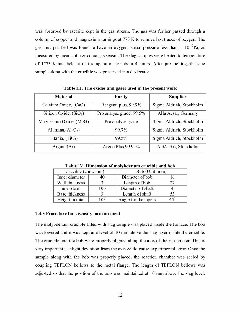
Table III. The oxides and gases used in the present work
Material Purity Supplier
Calcium Oxide, (CaO) Reagent plus, 99.9% Sigma Aldrich, Stockholm
Silicon Oxide, (SiO2) Pro analyse grade, 99.5% Alfa Aesar, Germany
Magnesium Oxide, (MgO) Pro analyse grade Sigma Aldrich, Stockholm
Alumina,(Al2O3) 99.7% Sigma Aldrich, Stockholm
Titania, (TiO2) 99.5% Sigma Aldrich, Stockholm
Argon, (Ar) Argon Plus,99.99% AGA Gas, Stockholm
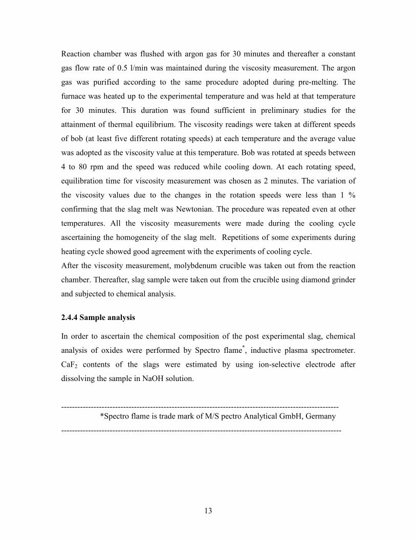
Table IV: Dimension of molybdenum crucible and bob
Crucible (Unit: mm) Bob (Unit: mm)
Inner diameter 40 Diameter of bob 16
Wall thickness 3 Length of bob 27
Inner depth 100 Diameter of shaft 4
Base thickness 3 Length of shaft 53
Height in total 103 Angle for the tapers 45o
2.4.3 Procedure for viscosity measurement
The molybdenum crucible filled with slag sample was placed inside the furnace. The bob
was lowered and it was kept at a level of 10 mm above the slag layer inside the crucible.
The crucible and the bob were properly aligned along the axis of the viscometer. This is
very important as slight deviation from the axis could cause experimental error. Once the
sample along with the bob was properly placed, the reaction chamber was sealed by
coupling TEFLON bellows to the metal flange. The length of TEFLON bellows was
adjusted so that the position of the bob was maintained at 10 mm above the slag level.
13
Reaction chamber was flushed with argon gas for 30 minutes and thereafter a constant
gas flow rate of 0.5 l/min was maintained during the viscosity measurement. The argon
gas was purified according to the same procedure adopted during pre-melting. The
furnace was heated up to the experimental temperature and was held at that temperature
for 30 minutes. This duration was found sufficient in preliminary studies for the
attainment of thermal equilibrium. The viscosity readings were taken at different speeds
of bob (at least five different rotating speeds) at each temperature and the average value
was adopted as the viscosity value at this temperature. Bob was rotated at speeds between
4 to 80 rpm and the speed was reduced while cooling down. At each rotating speed,
equilibration time for viscosity measurement was chosen as 2 minutes. The variation of
the viscosity values due to the changes in the rotation speeds were less than 1 %
confirming that the slag melt was Newtonian. The procedure was repeated even at other
temperatures. All the viscosity measurements were made during the cooling cycle
ascertaining the homogeneity of the slag melt. Repetitions of some experiments during
heating cycle showed good agreement with the experiments of cooling cycle.
After the viscosity measurement, molybdenum crucible was taken out from the reaction
chamber. Thereafter, slag sample were taken out from the crucible using diamond grinder
and subjected to chemical analysis.
2.4.4 Sample analysis
In order to ascertain the chemical composition of the post experimental slag, chemical
analysis of oxides were performed by Spectro flame*, inductive plasma spectrometer.
CaF2 contents of the slags were estimated by using ion-selective electrode after
dissolving the sample in NaOH solution.
-------------------------------------------------------------------------------------------------------
*Spectro flame is trade mark of M/S pectro Analytical GmbH, Germany
--------------------------------------------------------------------------------------------------------
14
2.5 Results and Discussion
Viscosity of quaternary and quinary systems
(Supplement I)
In the present work, slag viscosity was experimentally determined for CaO-SiO2-MgO-
Al2O3 and CaO-SiO2-MgO-Al2O3-TiO2 slags. These slags correspond to high alumina
blast furnace slags. Alumina was varied between 20-30%, MgO between 0-8%, TiO2
between 0-2% and CaO/SiO2 between 0.8-1.2. Temperature range of the investigation
was between 1673 to 1873 K. Effects of Al2O3, MgO and TiO2 on the viscosities of the
above slag systems were investigated.
Effect of basicity, TiO2 and silica activity on viscosity of slag was studied. In general, an
increase in basicity decreases the slag viscosity because silicate structure changes from
network to discrete anionic groups containing simple chains and/or rings as basic oxide
contents are increased 21,22
. Similar observation was found in present work. Change in
viscosity with respect to temperature was more at low levels of basicity. TiO2 doesn’t
have any significant effect on viscosity at low levels of basicity (~0.5). But at higher
basicity(~0.8), viscosity decreases with TiO2 addition.
Hadfield et al.23 have investigated the influence of TiO2 addition and temperature (~1573-
1873 K) on a blast furnace type slags in both homogeneous liquid melts and melts
containing solid particles. The slag contained, 18% MgO, 1.2% TiO2, 4% Al2O3, 1.2%S,
0.4% MnO,0.2%Fe and 1.3% others with a (CaO+MgO)/(SiO2+ Al2O3) ratio of 1.3.
These measurements showed, that at a given temperature, TiO2 reduces the viscosity of
blast furnace type slags. Sommerville and Bell5 also reported that TiO2 lowers the
viscosity of CaO-SiO2-MgO-Al2O3 –TiO2 slag, the decrease is lower at higher basicities.
Effect of silica activity on slag viscosity was studied and it was observed that slag
viscosity increases with increase in silica activity. On the other hand, with increase in
temperature, effect of silica activity on slag viscosity is minimized.
15
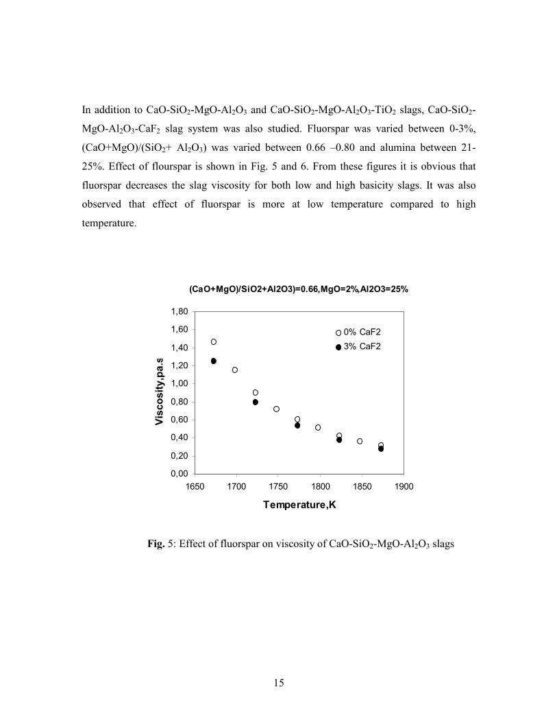
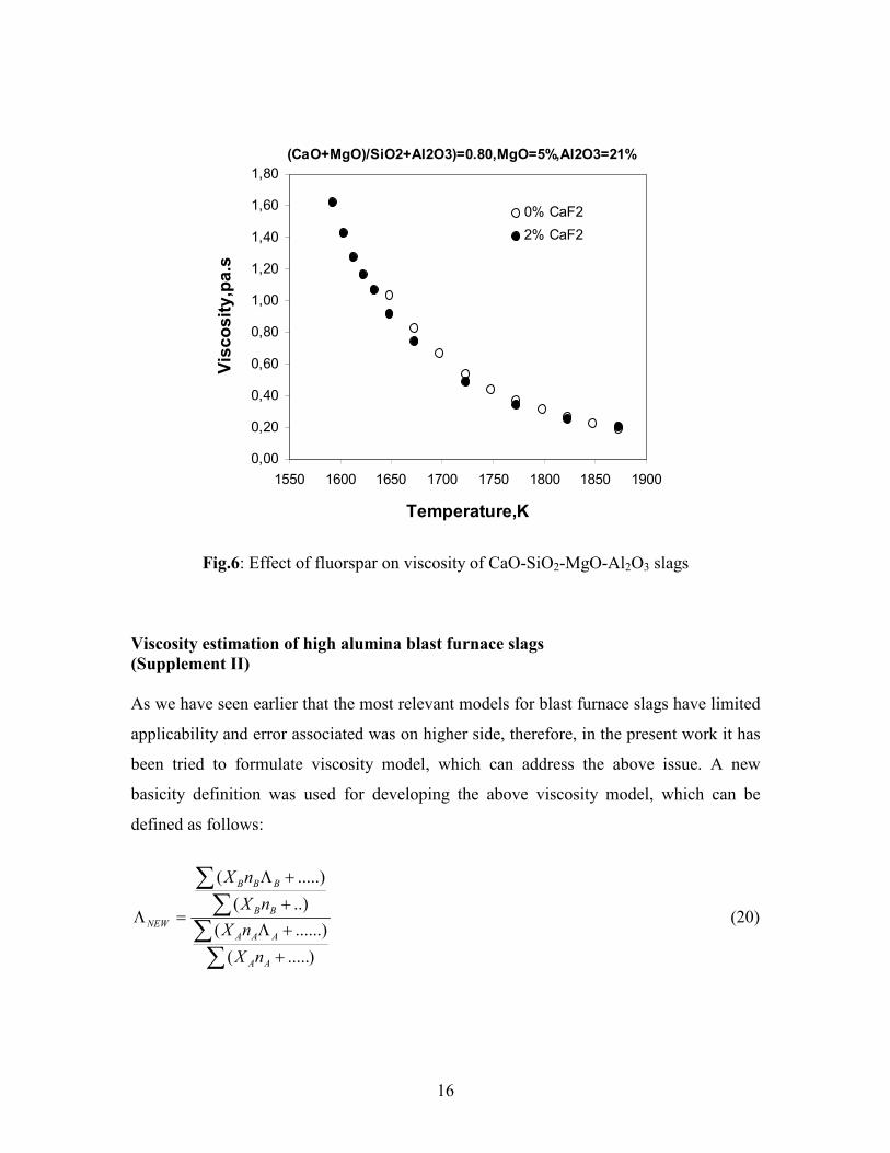
In addition to CaO-SiO2-MgO-Al2O3 and CaO-SiO2-MgO-Al2O3-TiO2 slags, CaO-SiO2-
MgO-Al2O3-CaF2 slag system was also studied. Fluorspar was varied between 0-3%,
(CaO+MgO)/(SiO2+ Al2O3) was varied between 0.66 –0.80 and alumina between 21-
25%. Effect of flourspar is shown in Fig. 5 and 6. From these figures it is obvious that
fluorspar decreases the slag viscosity for both low and high basicity slags. It was also
observed that effect of fluorspar is more at low temperature compared to high
temperature.
(CaO+MgO)/SiO2+Al2O3)=0.66,MgO=2%,Al2O3=25%
0,00
0,20
0,40
0,60
0,80
1,00
1,20
1,40
1,60
1,80
1650 1700 1750 1800 1850 1900
Temperature,K
Viscosity,pa.s
0% CaF2
3% CaF2
Fig. 5: Effect of fluorspar on viscosity of CaO-SiO2-MgO-Al2O3 slags
16
(CaO+MgO)/SiO2+Al2O3)=0.80,MgO=5%,Al2O3=21%
0,00
0,20
0,40
0,60
0,80
1,00
1,20
1,40
1,60
1,80
1550 1600 1650 1700 1750 1800 1850 1900
Temperature,K
Viscosity,pa.s
0% CaF2
2% CaF2
Fig.6: Effect of fluorspar on viscosity of CaO-SiO2-MgO-Al2O3 slags
Viscosity estimation of high alumina blast furnace slags
(Supplement II)
As we have seen earlier that the most relevant models for blast furnace slags have limited
applicability and error associated was on higher side, therefore, in the present work it has
been tried to formulate viscosity model, which can address the above issue. A new
basicity definition was used for developing the above viscosity model, which can be
defined as follows:
).....(
......)(
..)(
.....)(
∑∑∑
∑
+
+Λ
+
+Λ
=Λ
AA
AAA
BB
BBB
NEW
nX
nX
nX
nX
(20)
17
where AΛ and BΛ are the optical basicities of acidic and basic oxides respectively, AX
and BX are the mole fractions of acidic and basic oxides respectively, and nA and nB are
number of oxygen atoms associated with acidic and basic oxides ,respectively.
The above basicity is actually the ratio of optical basicity of basic oxide to acidic oxide.
The model developed in the present work is based on Arrhenius equation:
T
BA += lnlnη (21)
where 7374.63068.0ln −×−= BA (22)
347.31897.9 +Λ×−= NEWB (23)
The above model has been tried for a variety of slags ranging from low alumina (<15%
alumina) slags, high alumina (>15% and <30% alumina) slags, high TiO2 (>10% TiO2)
slags, high MgO slags (>15% MgO) slags, high basicity (CaO/SiO2:3-7) and low basicity
(CaO/SiO2:0.3-1.25) slags.
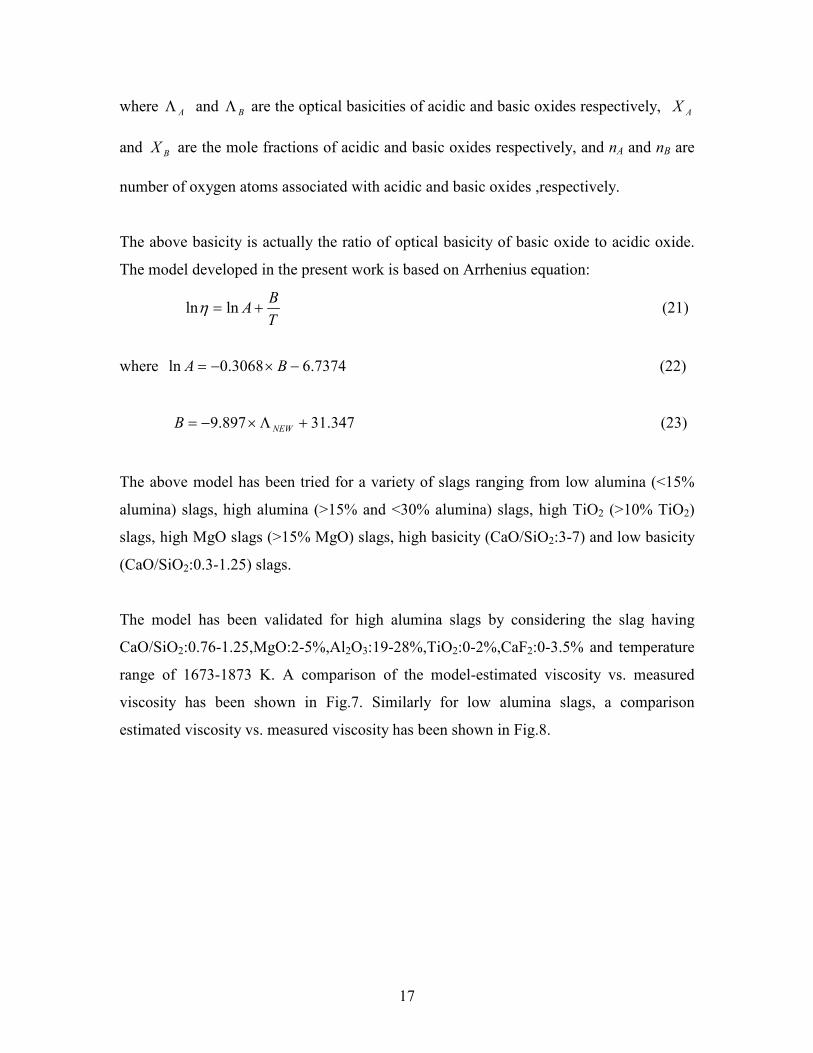
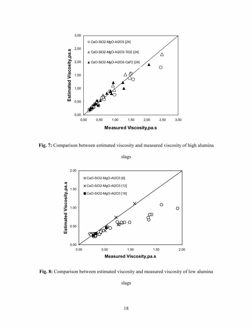
The model has been validated for high alumina slags by considering the slag having
CaO/SiO2:0.76-1.25,MgO:2-5%,Al2O3:19-28%,TiO2:0-2%,CaF2:0-3.5% and temperature
range of 1673-1873 K. A comparison of the model-estimated viscosity vs. measured
viscosity has been shown in Fig.7. Similarly for low alumina slags, a comparison
estimated viscosity vs. measured viscosity has been shown in Fig.8.
18
0,00
0,50
1,00
1,50
2,00
2,50
3,00
0,00 0,50 1,00 1,50 2,00 2,50 3,00
Measured Viscosity,pa.s
Estimated Viscosity,pa.s
CaO-SiO2-MgO-Al2O3 [24]
CaO-SiO2-MgO-Al2O3-TiO2 [24]
CaO-SiO2-MgO-Al2O3-CaF2 [24]
Fig. 7: Comparison between estimated viscosity and measured viscosity of high alumina
slags
0.00
0.50
1.00
1.50
2.00
0.00 0.50 1.00 1.50 2.00
Measured Viscosity,pa.s
Estimated Viscosity,pa.s
CaO-SiO2-MgO-Al2O3 [6]
CaO-SiO2-MgO-Al2O3 [12]
CaO-SiO2-MgO-Al2O3 [16]
Fig. 8: Comparison between estimated viscosity and measured viscosity of low alumina
slags
19
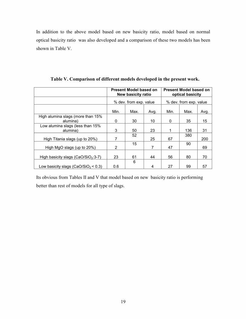
In addition to the above model based on new basicity ratio, model based on normal
optical basicity ratio was also developed and a comparison of these two models has been
shown in Table V.
Table V. Comparison of different models developed in the present work.
Present Model based on
New basicity ratio Present Model based on
optical basicity
% dev. from exp. value % dev. from exp. value
Min.
Max.
Avg. Min.
Max.
Avg.
High alumina slags (more than 15% alumina) 0
30 10 0
35 15
Low alumina slags (less than 15% alumina) 3
50 23 1
136 31
High Titania slags (up to 20%) 7 52
25 67 380
200
High MgO slags (up to 20%) 2 15
7 47 90
69
High basicity slags (CaO/SiO2:3-7) 23
61 44 56
80 70
Low basicity slags (CaO/SiO2 < 0.3) 0.6 6
4 27
99 57
Its obvious from Tables II and V that model based on new basicity ratio is performing
better than rest of models for all type of slags.
20
3. SULPHIDE CAPACITY OF BLAST FURNACE SLAGS
3.1 Thermodynamics of desulphurization
3.1.1 General aspects
During the process of iron and steelmaking, sulphur is undergoing continuous
redistribution between metal, slag and gas phases. In order to understand the conditions
governing the final sulphur content of the melt, it is necessary to understand the
distribution across the individual slag-metal and gas-slag interfaces.
3.1.2 Gas-slag distribution equilibria
Sulphur may be present in the slags either as sulphide or sulphate, i.e. as S2- or SO4
2-
ions, so the gas-slag equilibrium could follow either:
)(2
1)(
2
1 2
)(2
2
)(2 SOOS gasgas
−−+=+ (24)
Or
)()(2
3
2
1 2
4
2
2)(2 SOOOS gas
−−=++ (25)
Richardson and Fincham25 have found that if Henrian behaviour of S
2- and SO4
2- , ions
were assumed, the equation (24) is valid at constant slag composition at low oxygen
concentrations. For oxygen pressure below 10-6 atmposhere, equation (24) is favourable.
These authors have defined the sulphide capacity of the slag as follows:
p
pC
S
OSwt
S
2
2)%(= (26)
where wt pct S is the concentration of Sulphur in the slag, while pO2 and pS2 are partial
pressures of oxygen and sulphur in gas phase. Equation (25) is favorable for oxygen
21
pressures above 10-5 atmosphere. According to reaction (24), if sufficient O
2- ions are
available, and dissolved oxygen content in the metal is low enough, the reaction will take
place from left to right. A highly basic slag will certainly make available sufficient O2-
ions.
3.1.3 Slag-metal distribution equilibria
Most of the desulphurization treatments utilize metal-slag exchange reaction:
[S] + (O2-) = [O] + (S
2-) (27)
where “[ ]” and “( )” denotes solution in the metal and slag phase, respectively. It is seen
from equation (27) that transfer of sulphur into slag liberates a corresponding amount of
oxygen which is dissolved into the metal. The equilibrium constant of reaction (27) is
then:
)]([
])[(
2
2
aa
aaK
O
S
S
O
−
−
= (28)
Where K is equilibrium constant and “a” terms stand for the activities of the various
species.
It follows that,
][
)(
][
)( 2
2
2
a
aK
a
a
O
O
S
S−
−
−
= (29)
The activities of sulphur in the two phases can be expressed in terms of concentrations;
γsS Swta −− = 22 .)%( (30)
[ ] [ ] fa SSwt
S.%2 =− (31)
where fS and γS2- represent the activity coefficients of sulphur in the metal and the
sulphide ion in the slag respectively. The sulphur distribution ratio, LS is then:
22
[ ] [ ] γS
OKSwt
Swt f
a
aL
S
O
S−
−
==2
2
.)(
.%
)%( (32)
From this definition, it is obvious that higher Ls values are desirable for good sulphur
removal. From above equation, it is apparent that the sulphur distribution ratio will be
increased by increasing the basicity of the slag.
3.2 Relevance of present work on sulphide capacities in Ironmaking process
Steels with low sulphur are in great demand today as presence of sulphur is detrimental
for steel properties, especially toughness. Hence, blast furnace is expected to produce hot
metal with sulphur of the order of 0.005% or less 26. Therefore, it is always of great
interest to study the desulphurising capacity of slag or in other words, the sulphur
partition ratio between slag and hot metal. Earlier studies by Venkatadri et al.27, Ikabe et
al.28 and Young et al.
29 show that the sulfur partitioning between slag and metal attains
equilibrium in blast furnace. The study of Young et al.29 was based on cast-wise data
whereas other studies were based on mean daily data. These studies were made for slags
with Al2O3 content very close to 15% or less. These slags have liquidus temperatures
lower than furnace temperature and also low viscosity. These conditions are favorable for
attaining equilibrium. On the other hand, in Indian practice, slag is often high in alumina
(more than 18%). Sulphur partitioning for this type of slag has not been reported till now.
With a knowledge of the attainment of equilibrium during sulphur partition, sulphur in
the hot metal can be estimated based on sulphur input in the furnace since equilibrium
sulphur partition can be estimated from available models in the literature. Thus, it is
easier to control the hot metal sulphur by changing the slag chemistry.
Therefore, in the present work, an attempt was made to understand the approach of
sulphur partition ratio towards equilibrium using available sulphide capacity models in
the literature. Then, sulphide capacity experiments were performed to generate the data
for high alumina slags as practically no data available for such slags. This will help to
23
develop a better sulphide capacity model which can be further used to investigate the
slags which have been designed based on viscosity measurements.
3.3 Available Sulphide capacity models in the literature
There are number of models available in literature for sulphide capacity estimation of
blast furnace slags. Out of these models, some of the models which are most relevant to
present work have been discussed below.
Model by Sosinsky and Sommerville
An empirical model was developed by Sosinsky and Sommerville30 where composition
dependence of sulphide capacity was represented by optical basicity. The ratio of electron
donor power of the oxides in the glass to the electron donor power of “free” oxide ion
was termed as optical basicity by Duffy and Ingram 31. These authors
31 showed that
optical basicity of a slag can be calculated from the optical basicity of individual oxides
present in the slag using the relationship
......2211++= ΛΛΛ XX (33)
where Λi is the optical basicity of oxide with cation i and Xi is the equivalent cation
fraction.
Sosinsky and Sommerville30 derived the following empirical correlation between the
optical basicity, temperature, and sulphide capacity of slag:
2.25.6.43)5464022690
(log −Λ×+Λ×−
=T
C S (34)
Model by Young and Co Workers
Young et al.26 modified the Sosinsky and Sommerville’s model as it was not accurate
enough particularly at high basicity (or in high sulphide capacity)region.They
24
incorporated slag chemistry in the model and suggested following equations for sulphide
capacity:
For Λ<0.8
)(%02275.0)(%02223.0)11710(82.23.84.42913.13
322
2
log OAlSiOCTS
×−×−−×−Λ×+−= Λ (35)
For Λ≥ 0.8
)(%0005144.0.25871697
7197.0.4808.06261.02
FeOTT
C S×+
Λ×−+×+Λ×+−= Λ
(36)
3.4 Present work
3.4.1 Materials
The materials used in the present work are listed in Table VI. All the oxides were heated
to 1273 K for 12h in a muffle furnace to remove any trace of moisture. The samples were
then cooled rapidly and stored in desiccators.
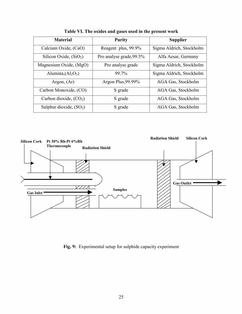
3.4.2 Experimental Procedure
The experimental setup is shown in Fig.9. All the experiments were carried out in a
horizontal tubular resistance furnace where temperature can be maintained up to 1973 K.
This furnace consists of an alumina tube having 1.2 m length and 0.058 m inner diameter.
The even temperature zone was measured and was found to be over a length of 0.2m,
temperature variation being within ±1 K. Two radiation shields made of alumina were
also used to maintain even temperature zone inside the furnace and they were placed
0.1m away from the sample.
25
Table VI. The oxides and gases used in the present work
Material Purity Supplier
Calcium Oxide, (CaO) Reagent plus, 99.9% Sigma Aldrich, Stockholm
Silicon Oxide, (SiO2) Pro analyse grade,99.5% Alfa Aesar, Germany
Magnesium Oxide, (MgO) Pro analyse grade Sigma Aldrich, Stockholm
Alumina,(Al2O3) 99.7% Sigma Aldrich, Stockholm
Argon, (Ar) Argon Plus,99.99% AGA Gas, Stockholm
Carbon Monoxide, (CO) S grade AGA Gas, Stockholm
Carbon dioxide, (CO2) S grade AGA Gas, Stockholm
Sulphur dioxide, (SO2) S grade AGA Gas, Stockholm
Fig. 9: Experimental setup for sulphide capacity experiment
Silicon Cork Pt 30% Rh-Pt 6%Rh
Thermocouple Radiation Shield
Gas Inlet Samples
Radiation Shield Silicon Cork
Gas Outlet
26
Furnace was controlled through PID controller, supplied by Eurotherm, 902 series. Two
different sets of Pt 30%Rh-Pt 6%Rh thermocouples were used. One thermocouple was
fixed close to the furnace heating element, just outside the furnace tube in order to control
the furnace temperature. The other thermocouple was fixed just above the sample to
measure the sample temperature.
A gas mixture consisting of Ar-CO-CO2-SO2 was used for equilibration with liquid slag.
The furnace was heated up to target temperature with argon gas flushing at a flow rate of
400 ml/min. Once target temperature was achieved, gas flow rates of Ar, CO, CO2 and
SO2 were changed to 200, 100, 80 and 20 ml/min respectively, keeping the total gas flow
rate 400 ml/min. Gas flow rates of different gases were estimated so that the partial
pressure of oxygen inside the furnace could generally be maintained at less than 10-7 atm.
Partial pressures of various gaseous species at the experimental temperatures are given in
Table VII. Purities of gases used are shown in Table VI. Gas flow rates were controlled
using Bronkhorst hi-tech mass flow meter. All the four gases were purified before they
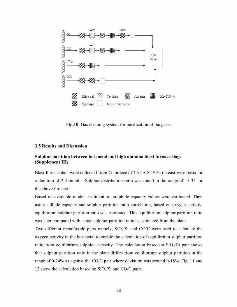
entered the furnace. The gas cleaning system for purification of the gases is shown in the
Fig. 10. Argon gas was passed through column of silica gel and Mg(ClO4)2 to remove
traces of moisture. CO2 impurity was removed by passing the gas through column of
ascarite. The argon gas was further passed through copper and magnesium turnings at
773 K to remove traces of oxygen. The moisture and CO2 impurity in the CO gas were
removed by silica gel and ascarite respectively. The CO gas was further passed through
copper at 773 K to remove traces of oxygen. CO2 gas was purified by passing it through
silica gel and Mg(ClO4)2 to remove traces of moisture. SO2 gas was purified by passing it
through silica gel twice.
Partial pressure of oxygen inside the furnace was maintained between 3.5× 10⁻⁸ and
2.0×10⁻⁷ atm so that sulphur entered the slag in the form of sulphide instead of sulphate.
Partial pressure of oxygen and sulphur in the gas mixture was calculated using
Thermocalc with SSUB3 database. Slag samples were prepared by mixing appropriate
proportions of the reagents in the ball mill, followed by pressing it into small pellets of
approximately 1.0 g. Platinum cups (made of 0.127 mm platinum foil, 99.9% (metal
27
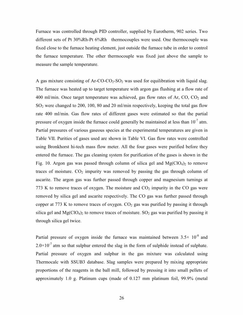
basis)) were used to hold the samples. These samples were kept on alumina boats and
pushed inside the furnace. Samples were kept inside the furnace for approximately 6
hours at the target temperature. Time required to achieve the equilibrium was established
by comparing the equilibrium sulphur values for 6 hours and 15 hours duration. The
equilibrium sulphur values were found to be very close to each other. Hence, for
subsequent experiments, equilibrium time for sulphur saturation in the slag was taken as
6 hours. After equilibration, the samples were pulled towards the cold end of the furnace
using a silica tube. Samples were taken out from the platinum crucibles and were
subjected to chemical analysis. The practice of post experimental analysis was followed
for all samples.
Table VII. Experimental partial pressure of various gaseous species at the
experimental temperatures
Partial pressure (atm.) Species
1773 K 1823 K 1873 K
Ar 5.059. 10-1
5.048. 10-1
5.038. 10-1
CO 2.043. 10-1
2.117. 10-1
2.185. 10-1
CO2 2.499.10-1
2.418.10-1
2.343.10-1
SO2 2.568.10-2 2.918.10
-2 3.234.10
-2
S2 1.060.10-2 8.662.10
-3 6.855.10
-3
O2 3.560.10-8 8.759.10
-8 2.061.10
-7
28
Fig.10: Gas cleaning system for purification of the gases
3.5 Results and Discussion
Sulphur partition between hot metal and high alumina blast furnace slags
(Supplement III)
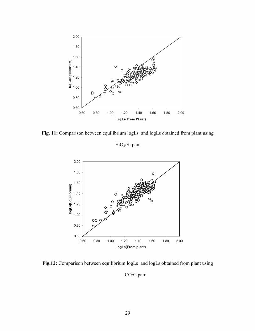
Blast furnace data were collected from G furnace of TATA STEEL on cast-wise basis for
a duration of 2-3 months. Sulphur distribution ratio was found in the range of 15-35 for
the above furnace.
Based on available models in literature, sulphide capacity values were estimated. Then
using sulhide capacity and sulphur partition ratio correlation, based on oxygen activity,
equilibrium sulphur partition ratio was estimated. This equilibrium sulphur partition ratio
was later compared with actual sulphur partition ratio as estimated from the plant.
Two different metal/oxide pairs namely, SiO2/Si and CO/C were used to calculate the
oxygen activity in the hot metal to enable the calculation of equilibrium sulphur partition
ratio from equilibrium sulphide capacity. The calculation based on SiO2/Si pair shows
that sulphur partition ratio in the plant differs from equilibrium sulphur partition in the
range of 0-24% as against the CO/C pair where deviation was around 0-18%. Fig. 11 and
12 show the calculation based on SiO2/Si and CO/C pairs.
29
0.60
0.80
1.00
1.20
1.40
1.60
1.80
2.00
0.60 0.80 1.00 1.20 1.40 1.60 1.80 2.00
logLs(From Plant)
logLs(Equilibrium)
Fig. 11: Comparison between equilibrium logLs and logLs obtained from plant using
SiO2/Si pair
0.60
0.80
1.00
1.20
1.40
1.60
1.80
2.00
0.60 0.80 1.00 1.20 1.40 1.60 1.80 2.00
logLs(From plant)
logLs(Equilibrium)
Fig.12: Comparison between equilibrium logLs and logLs obtained from plant using
CO/C pair
30
Sulphide capacity of high alumina blast furnace slags
(Supplement IV)
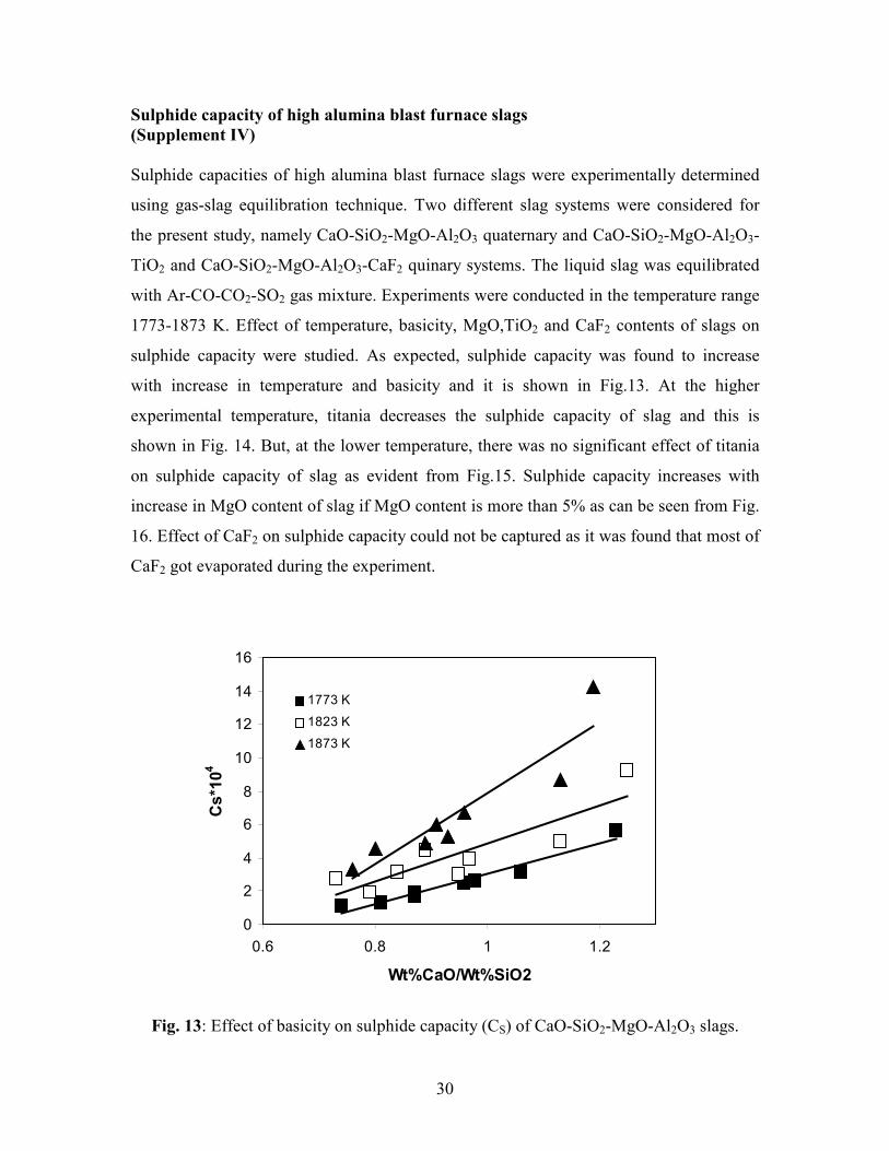
Sulphide capacities of high alumina blast furnace slags were experimentally determined
using gas-slag equilibration technique. Two different slag systems were considered for
the present study, namely CaO-SiO2-MgO-Al2O3 quaternary and CaO-SiO2-MgO-Al2O3-
TiO2 and CaO-SiO2-MgO-Al2O3-CaF2 quinary systems. The liquid slag was equilibrated
with Ar-CO-CO2-SO2 gas mixture. Experiments were conducted in the temperature range
1773-1873 K. Effect of temperature, basicity, MgO,TiO2 and CaF2 contents of slags on
sulphide capacity were studied. As expected, sulphide capacity was found to increase
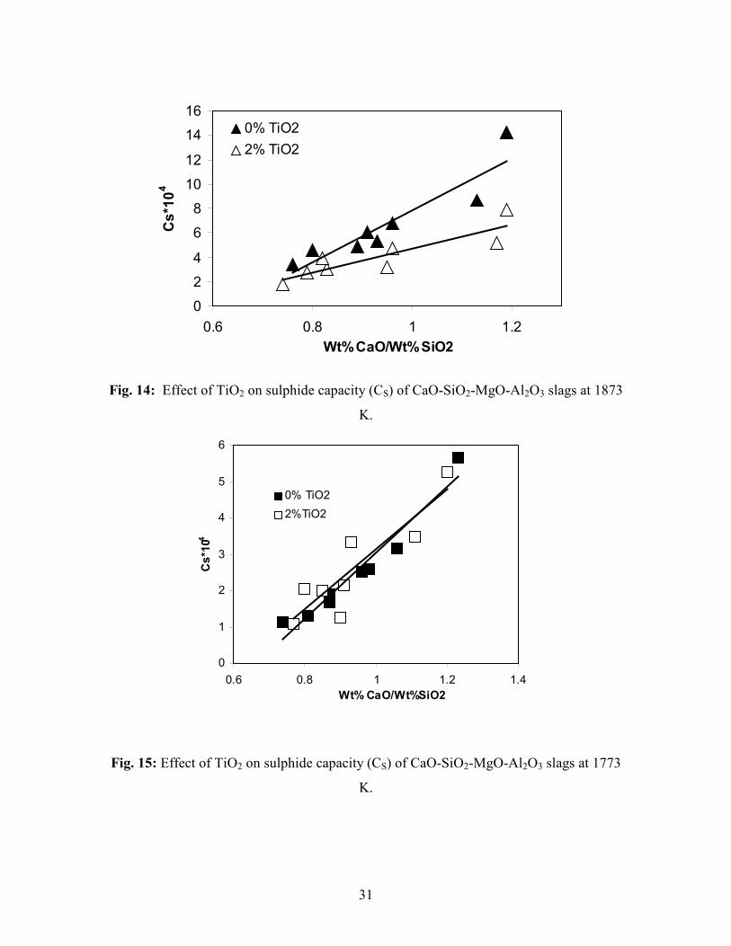
with increase in temperature and basicity and it is shown in Fig.13. At the higher
experimental temperature, titania decreases the sulphide capacity of slag and this is
shown in Fig. 14. But, at the lower temperature, there was no significant effect of titania
on sulphide capacity of slag as evident from Fig.15. Sulphide capacity increases with
increase in MgO content of slag if MgO content is more than 5% as can be seen from Fig.
16. Effect of CaF2 on sulphide capacity could not be captured as it was found that most of
CaF2 got evaporated during the experiment.
0
2
4
6
8
10
12
14
16
0.6 0.8 1 1.2
Wt%CaO/Wt%SiO2
Cs*104
1773 K
1823 K
1873 K
Fig. 13: Effect of basicity on sulphide capacity (CS) of CaO-SiO2-MgO-Al2O3 slags.
31
0
2
4
6
8
10
12
14
16
0.6 0.8 1 1.2
Wt%CaO/Wt%SiO2
Cs*104
0% TiO2
2% TiO2
Fig. 14: Effect of TiO2 on sulphide capacity (CS) of CaO-SiO2-MgO-Al2O3 slags at 1873
K.
0
1
2
3
4
5
6
0.6 0.8 1 1.2 1.4
Wt% CaO/Wt%SiO2
Cs*104
0% TiO2
2%TiO2
Fig. 15: Effect of TiO2 on sulphide capacity (CS) of CaO-SiO2-MgO-Al2O3 slags at 1773
K.
32
1.00
1.50
2.00
2.50
3.00
3.50
4.00
4.50
5.00
5.50
6.00
0.7 0.8 0.9 1 1.1 1.2 1.3
Wt% CaO/Wt%SiO2
Cs*104
2%MgO
5%MgO
7%MgO
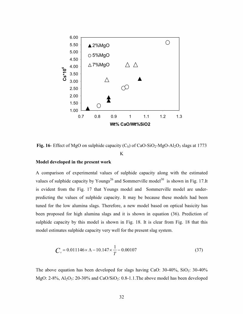
Fig. 16- Effect of MgO on sulphide capacity (CS) of CaO-SiO2-MgO-Al2O3 slags at 1773
K
Model developed in the present work
A comparison of experimental values of sulphide capacity along with the estimated
values of sulphide capacity by Youngs26 and Sommerville model
30 is shown in Fig. 17.It
is evident from the Fig. 17 that Youngs model and Sommerville model are under-
predicting the values of sulphide capacity. It may be because these models had been
tuned for the low alumina slags. Therefore, a new model based on optical basicity has
been proposed for high alumina slags and it is shown in equation (36). Prediction of
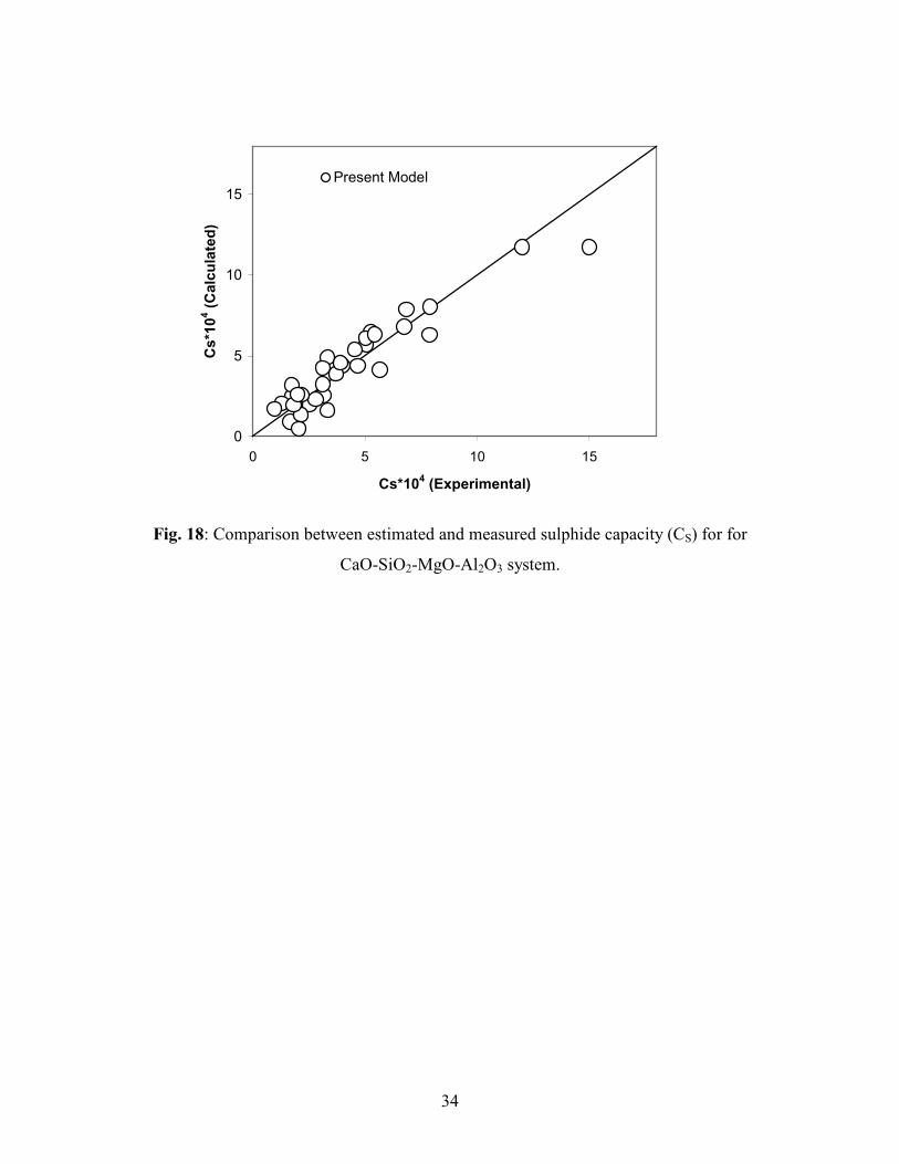
sulphide capacity by this model is shown in Fig. 18. It is clear from Fig. 18 that this
model estimates sulphide capacity very well for the present slag system.
00107.01
147.10011146.0 −×−Λ×=T
C s (37)
The above equation has been developed for slags having CaO: 30-40%, SiO2: 30-40%
MgO: 2-8%, Al2O3: 20-30% and CaO/SiO2: 0.8-1.1.The above model has been developed
33
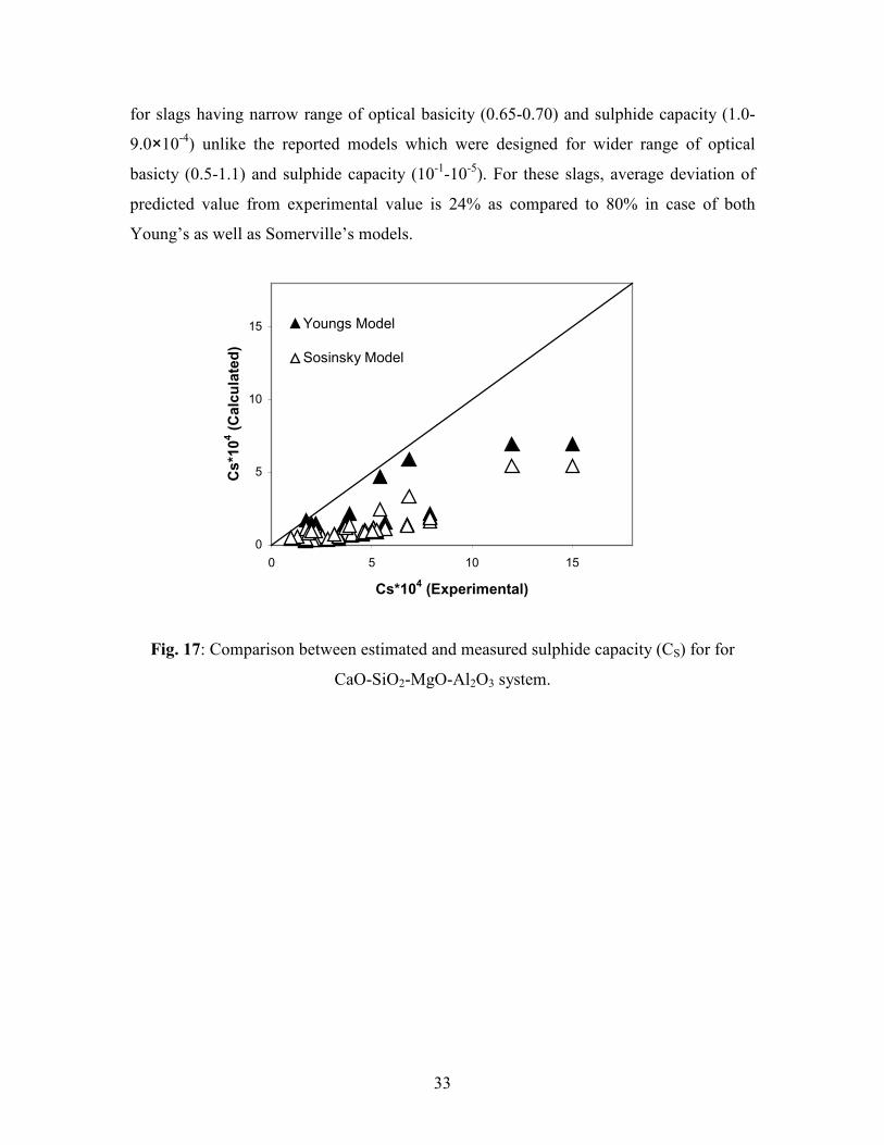
for slags having narrow range of optical basicity (0.65-0.70) and sulphide capacity (1.0-
9.0×10⁻⁴) unlike the reported models which were designed for wider range of optical
basicty (0.5-1.1) and sulphide capacity (10-1-10
-5). For these slags, average deviation of
predicted value from experimental value is 24% as compared to 80% in case of both
Young’s as well as Somerville’s models.
0
5
10
15
0 5 10 15
Cs*104 (Experimental)
Cs*104 (Calculated)
Youngs Model
Sosinsky Model
Fig. 17: Comparison between estimated and measured sulphide capacity (CS) for for
CaO-SiO2-MgO-Al2O3 system.
34
0
5
10
15
0 5 10 15
Cs*104 (Experimental)
Cs*104 (Calculated)
Present Model
Fig. 18: Comparison between estimated and measured sulphide capacity (CS) for for
CaO-SiO2-MgO-Al2O3 system.
35
4. PLANT TRIALS
Strategy to be adopted for reduction in the slag volume
An attempt is made to apply the viscosity and sulphide capacity model developed in the
present work to step-by-step reduce the slag volume in the blast furnace. A-Blast Furnace
of TATA STEEL is considered as a typical case. Given the Al2O3 input from the raw
materials – about 60 kg Al2O3 / THM input coming mainly from ore, sinter and coke- any
attempt to reduce slag volume should result in higher alumina concentration in the slag.
The following steps were selected for reduction in slag volume:
Step-1: As a first step, this can be done by reduction in direct addition of quartzite in blast
furnace to increase slag basicity CaO/SiO2 from a level of 0.92 to about 1.0. A
decrease in slag rate of about 10 kg/THM and Al2O3 concentration by 0.6% will
result. Higher basicity will also help in decreasing the slag viscosity by nearly
10% and nearly 25% increase in sulphide capacity compared to the base level,
Table VIII.
Step-2: A further decrease of 10 kg/THM in slag volume can be attempted by reducing
the sinter CaO from 9.5% to 9.0%, by concentrating slag alumina by an additional
0.6% and keeping the slag basicity at the same level of 1.0 and maintaining the
same sulphide capacity of the slag. In this analysis, it is assumed that 9.0% CaO
sinter of good quality can be produced in near future.
Step-3: In this step, MgO in slag can also be marginally increased from 7% to 8% level
with further improvement in viscosity and sulphide capacity of slag. A correlation
between MgO required and alumina concentration is shown in Fig. 19.
By the above action steps, it is possible to reduce slag volume by about 20 kg/THM
ensuring a good viscosity and sulphide capacity of slag even while slag basicity and
alumina concentration in slag are increased (Table VIII).
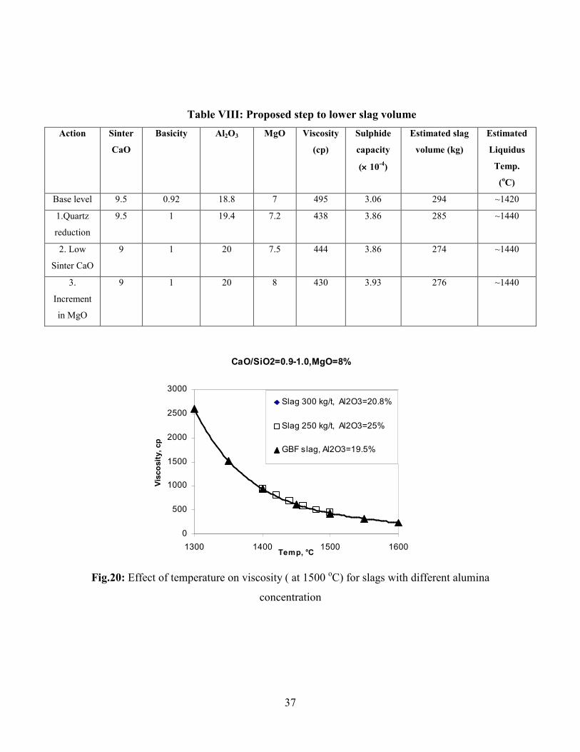
There are also concerns on the effect of higher basicity and alumina contents on the
liquidus temperature of slag. Table VIII also shows the results of liquidus temperature
measured using Slag Atlas for different slag compositions. It was found that with increase
in basicity from 0.9 to 1.0 will increase the liquidus temperature by around 20oC.
36
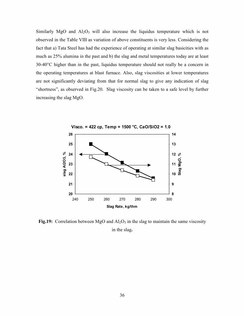
Similarly MgO and Al2O3 will also increase the liquidus temperature which is not
observed in the Table VIII as variation of above constituents is very less. Considering the
fact that a) Tata Steel has had the experience of operating at similar slag basicities with as
much as 25% alumina in the past and b) the slag and metal temperatures today are at least
30-40°C higher than in the past, liquidus temperature should not really be a concern in
the operating temperatures at blast furnace. Also, slag viscosities at lower temperatures
are not significantly deviating from that for normal slag to give any indication of slag
“shortness”, as observed in Fig.20. Slag viscosity can be taken to a safe level by further
increasing the slag MgO.
Visco. = 422 cp, Temp = 1500 °C, CaO/SiO2 = 1.0
20
21
22
23
24
25
26
240 250 260 270 280 290 300
Slag Rate, kg/thm
slag Al2O3, %
8
9
10
11
12
13
14
Slag MgO, %
Fig.19: Correlation between MgO and Al2O3 in the slag to maintain the same viscosity
in the slag.
37
Table VIII: Proposed step to lower slag volume
Action Sinter
CaO
Basicity Al2O3 MgO Viscosity
(cp)
Sulphide
capacity
(×××× 10-4)
Estimated slag
volume (kg)
Estimated
Liquidus
Temp.
(oC)
Base level 9.5 0.92 18.8 7 495 3.06 294 ~1420
1.Quartz
reduction
9.5 1 19.4 7.2 438 3.86 285 ~1440
2. Low
Sinter CaO
9 1 20 7.5 444 3.86 274 ~1440
3.
Increment
in MgO
9 1 20 8 430 3.93 276 ~1440
CaO/SiO2=0.9-1.0,MgO=8%
0
500
1000
1500
2000
2500
3000
1300 1400 1500 1600Temp, °C
Viscosity, cp
Slag 300 kg/t, Al2O3=20.8%
Slag 250 kg/t, Al2O3=25%
GBF slag, Al2O3=19.5%
Fig.20: Effect of temperature on viscosity ( at 1500 oC) for slags with different alumina
concentration
38
Recommendation
Based on above strategy, it was recommended in the plant to increase slag basicity from
0.9 to 1.0 by reduction in quartzite addition, increasing the MgO content from 7% to 8%.
By doing so, slag alumina will concentrate by about 1.5 %, which will reduce the slag
rate by about 20 kg/thm and still ensure better slag viscosity and sulphide capacity.
These steps may lead to increase in alkali concentration, which can be minimized by
simultaneous use of low alkali limestone like Bhutan Limestone during the trial period.
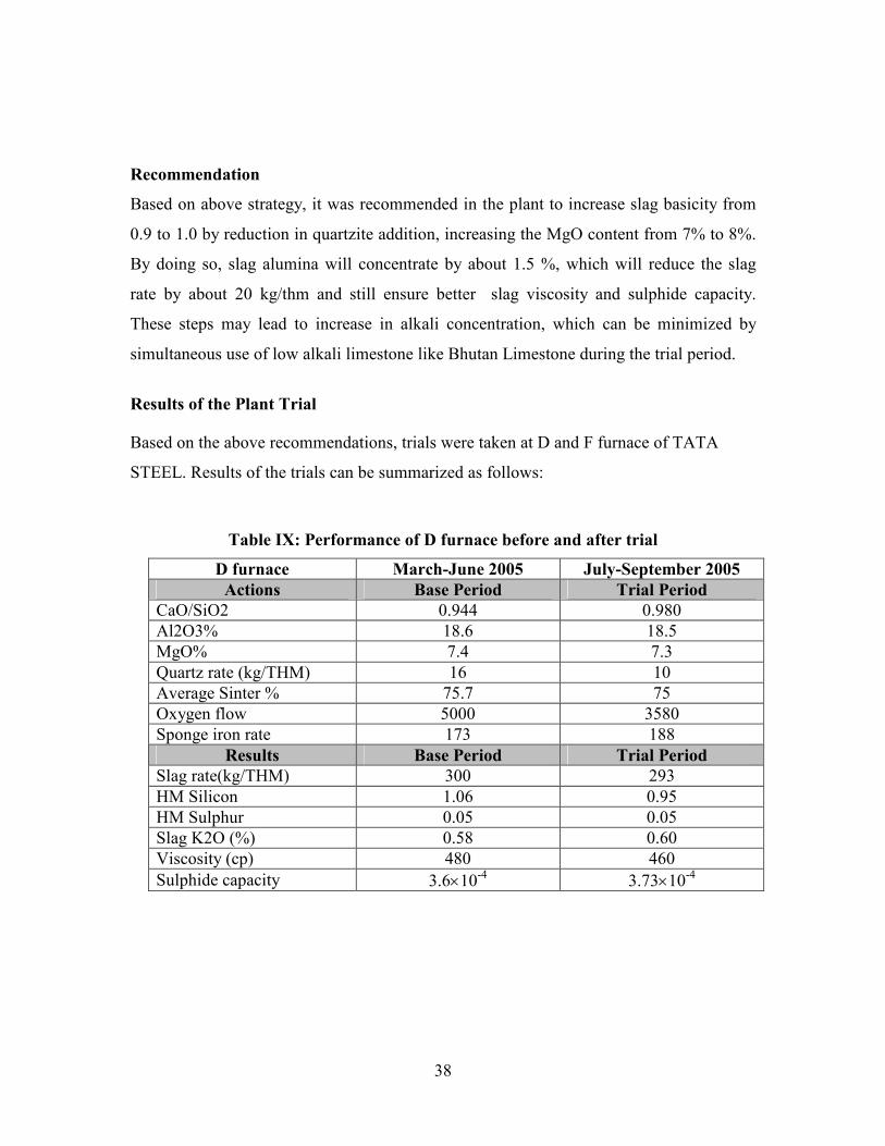
Results of the Plant Trial
Based on the above recommendations, trials were taken at D and F furnace of TATA
STEEL. Results of the trials can be summarized as follows:
Table IX: Performance of D furnace before and after trial
D furnace March-June 2005 July-September 2005
Actions Base Period Trial Period
CaO/SiO2 0.944 0.980
Al2O3% 18.6 18.5
MgO% 7.4 7.3
Quartz rate (kg/THM) 16 10
Average Sinter % 75.7 75
Oxygen flow 5000 3580
Sponge iron rate 173 188
Results Base Period Trial Period
Slag rate(kg/THM) 300 293
HM Silicon 1.06 0.95
HM Sulphur 0.05 0.05
Slag K2O (%) 0.58 0.60
Viscosity (cp) 480 460
Sulphide capacity 3.6×10⁻⁴ 3.73×10⁻⁴
39
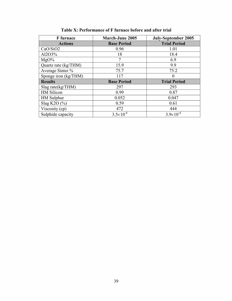
Table X: Performance of F furnace before and after trial
F furnace March-June 2005 July-September 2005
Actions Base Period Trial Period
CaO/SiO2 0.96 1.01
Al2O3% 18 18.4
MgO% 7 6.9
Quartz rate (kg/THM) 15.9 9.9
Average Sinter % 75.7 75.2
Sponge iron (kg/THM) 117 0
Results Base Period Trial Period
Slag rate(kg/THM) 297 293
HM Silicon 0.99 0.87
HM Sulphur 0.052 0.047
Slag K2O (%) 0.59 0.61
Viscosity (cp) 472 444
Sulphide capacity 3.5×10⁻⁴ 3.9×10⁻⁴

40
5. SUMMARY AND CONCLUSIONS
In the present work, viscosity and sulphide capacities of high alumina blast furnace slags
were measured. The slag systems considered were CaO-SiO2-MgO-Al2O3 quaternary and
CaO-SiO2-MgO-Al2O3-TiO2 quinary. It was found that with increase in silica activity in
the range of 0.1 to 0.4, viscosity of slag increases, the increase being steeper below
liquidus temperature. The data developed in the present work were later used to develop
models for viscosity and sulphide capacity estimation of blast furnace slags. The viscosity
model was found applicable for all kinds of blast furnace slags ranging from low to high
alumina, low to high basicity, low to high MgO and for low to high TiO2 slags preferably
above liquidus temperature. A new parameter called ‘New Basicity Ratio’ has been used
to develop the above model.
Sulphide capacity increases with increase in basicity and MgO beyond 5 pct.At high
temperature, TiO2 affects the sulphide capacity of slag. The sulphide capacity is found to
decrease with increase in TiO2 content. The model developed for sulphide capacity is
applicable for high alumina slag systems with alumina more than 15 pct.
Based on above finding some plant trials have been taken and results were found
encouraging as slag volume was reduced by about 4-7 kg per ton of hot metal with some
improvement in viscosity and sulphide capacity.
41
6. FUTURE WORK
The future work is expected to be carried out in following areas:
1. The present investigation mainly deals with final slag in the blast furnace.
This could be further extended to bosh slag which has high basicity and
high FeO in the slag.
2. In addition to viscosity and sulphide capacity, alkali capacity and liquidus
temperature of final slags can be measured to design the slag in better
way.
3. Development of a comprehensive model for sulphide capacities and
viscosities.
42
7._REFERENCES
1. V. Ya. Miller and N.M. Babushkin, STAL,1961,May 1961,pp314-317
2. A. Ohno, and H.U. Ross, Can. Met. Quaterly,1963, Vol.2,p.243
3. E.U. Chukukere and H.U. Ross, Can. Met. Quaterly,1967, Vol.6,p.137
4. M. Higuchi, Iron & Steelmaker, June 1978,p.33
5. I.D. Sommerville and H.B. Bell, Can. Met. Quaterly, 1982, Vol.21,pp.145-155
6. T. Iida,H. Sakai, Y. Kita, K. Shigeno, ISIJ 2000,pp. S110-114.
7. N. Saito, N. Hori,K. Nakashima, and K. Mori, Met. and Materials Trans.,
Vol.34B,Oct. 2003, pp.509-516.
8. E.T. Turkdogan, and Patrica M. Bills, Ceramic Bulletin, Vol. 39,
No.11,1960,pp.682-686.
9. J.R. Kim, Y. S. LEE, D. J. MIN, S. M. Jung and S. H. Yi, 2004,ISIJ, pp.1291-
1297.
10. Y.S. Lee, D. J. Min, S. M. Jung, and S. H. Yi,,2004, ISIJ,pp.1283-1290.
11. J. S.Machin and D.L. Hanna, Vol.28, No.11, Journal of American Ceramic
Society, 1945.pp.310-316.
12. M. Nakamoto, T. Tanaka, J. LEE, and T. V Sui,Vol.44,ISIJ
2004,No.12,pp.2115-2119.
13. J.D. Mackenzie: Adv. Inorg. Chem.. Radiochem, 4 (1962),p.293
14. T. Iida, H. Sakai, Y.Kita and K.Shigeno, ISIJ International, Supplement
2000,Vol.40,pp.S110-S114.
15. G. Urbain, Steel Research, 1987, 58, pp.111-116.
16. K. C. Mills and S. Sridhar, Ironmaking and Steelmaking, 1999, 26, pp.262-
268.
17. H. S. Ray and S. Pal, Ironmaking and Steelmaking, 2004, 31, pp.125-130.
18. J.A. Duffy and M.D. Ingram: J. Amer. Chem. Soc., 1971, 93, pp.6448-54.
19. Japanese patent No. 115341
20. K. C. Mills, ISIJ International, vol.33, 1993, No.1, pp.148-155.
21. J. O’M. Bockris and D.C. Lowe : proc. Roy. Soc., (London), A, 1954, p.423.
22. L. Zhang and S. Jahanshahi: Metall. Mater. Trans. B, 1998, vol.29, p.177.
43
23. G. Hadfield, G. G. Charette, and H. Y. Lee,. J Metals, 1972, vol. 24(9), pp.37-
40.
24. A. Shankar, Märten Görnerup, A.K. Lahiri, S. Seetharaman,Sumitted for
publication in Met. and Materials Trans.B,2007
25. C.J.B. Fincham, F.D. Richardson,Proc. R. Soc. A(1954),40
26. R.W. Young, J.A. Duffy. G.J. Hassall, and Z. Xu.: Ironmaking and
Steelmaking, 1992,19, pp.201-219.
27. A.S. Venkatadri and H.B. Bell : ibid., 1969, 207, 1110
28. K. Ikabe, N. Tsuchiya, G. Fukutaske, and Y. Takada: Kwasaki Steel Tech.
Res. Lab. Rep., English Translation BISI 13657, 14 May 1974.
29. D.J. Young and C.J. Cripps Clark: Ironmaking and Steelmaking, 1980, 209-
214
30. D.J. Sosinsky and I.D. Sommerwhile:Metall. Trans.B, 1986,17B,331-337.
31. A Duffy and M.D. Ingram: J.Amer. Chem. Soc., 1971,93,6448-54