Embed Size (px)
Citation preview
Title Study on Multi-DOF Spherical Actuator andIntelligent Control
Author(s) 朱, 程鉉
Citation
Issue Date
Text Version ETD
URL https://doi.org/10.18910/67141
DOI 10.18910/67141
rights
博士学位論文
Study on Multi-DOF Spherical
Actuator
And Intelligent Control
Junghyun Chu
2017 年 7 月
大阪大学大学院工学研究科
知能・機能創成工学専攻

- 1 -
Abstract
Spherical actuators have been regarded as a new trend in robotics due to their
superior performances. The spherical actuator is able to perform multi degree of
freedom motions using only one actuator. Therefore, a multi-DOF device using the
spherical actuator can reduce its weight and the structure can be simple.
Adaptive neuro-fuzzy inference systems (ANFIS) has the advantage of expert
knowledge of the fuzzy inference system (FIS) and learning capabilities of the neural
networks (NN) for control of a nonlinear system. The membership function parameters
are tuned using a combination of the least squares estimation and back propagation.
Therefore, a control method using ANFIS will produce more accurate results compared
with other control methods.
In Chapter 1, the comparison of a multi-degree-of-freedom mechanism combining a
spherical actuator and plurality of motors are conducted, and the advantage of the
spherical actuator and the significance of development are shown. Previous research
examples of the spherical actuator are shown. In addition, the purpose of this research,
“Proposal of 3-degree-of-freedom spherical actuator using voice coil motor principle ”
and “Feedback control using adaptive neuro-fuzzy inference system (ANFIS) control
method” are shown.
In Chapter 2, in order to achieve a large angle of the tilt motion, high tilt torque,
easy control and good dynamic performance, the design flow chart is considered. A new
structure is described for the spherical actuator. The structure of the proposed
actuator and its operating principle are described.
In Chapter 3, explained the proposed intelligent control method (ANFIS) for
feedback control of spherical actuator.
- 2 -
In Chapter 4, Verification of a 2-DOF spherical actuator and proposed spherical
actuator using ANFIS feedback control method is described. Firstly, in order to verify
the ANFIS, a prototype of 2-DOF spherical actuator is described. After that, each
characteristic of the proposed spherical actuator is computed by FEM simulations.
Finally, the proposed spherical actuator with ANFIS control is described.
In Chapter 5, the contents of Chapters 2 to 4 are summarized and conclusion of
thesis.
- 3 -
Contents
Abstract .................................................................................................................. - 1 -
Introduction ........................................................................................... - 5 - Chapter 1
1.1 Research background ..................................................................................... - 5 -
1.1.1 Spherical actuator technology ................................................................. - 8 -
1.2 Previous researches ....................................................................................... - 8 -
1.2.1 Induction spherical actuator ................................................................... - 9 -
1.2.2 Ultrasonic spherical actuator ................................................................ - 10 -
1.2.3 Variable reluctance spherical actuator .................................................. - 11 -
1.3 Objective of research ................................................................................... - 13 -
1.3.1 Requirements of spherical actuator and feedback control ...................... - 13 -
1.3.2 Objective ............................................................................................... - 14 -
1.3.3 Scope ..................................................................................................... - 14 -
1.4 Concept of the proposed spherical actuator ................................................. - 15 -
Spherical Actuator ............................................................................... - 18 - Chapter 2
2.1 Structure of actuator ................................................................................... - 18 -
2.1.1 Features of the proposed spherical actuator .......................................... - 18 -
2.1.2 Design flow chart .................................................................................. - 18 -
2.1.3 Design considerations ........................................................................... - 19 -
2.1.4 Conceptual design ................................................................................. - 21 -
2.1.5 Modeling ............................................................................................... - 24 -
2.1.6 Design optimization .............................................................................. - 25 -
2.1.7 Final design .......................................................................................... - 27 -
2.2 Operating principle of actuator ................................................................... - 28 -
Intelligent Control Method................................................................... - 32 - Chapter 3
3.1 Adaptive Neuro-Fuzzy Inference System (ANFIS) ....................................... - 32 -
Verification .......................................................................................... - 38 - Chapter 4
- 4 -
4.1 Experiments of 2-DOF spherical actuator with intelligent control .............. - 38 -
4.1.1 Basic structure of 2-DOF spherical actuator ......................................... - 38 -
4.1.2 Proposed controller scheme and prototype ............................................ - 40 -
4.1.3 Experimental results ............................................................................ - 43 -
4.2 Analyzed results of 3-DOF spherical actuator with intelligent control ........ - 49 -
4.2.1 Characteristic analysis ......................................................................... - 49 -
4.2.1.1 Analysis method ................................................................................. - 49 -
4.2.1.2 Static torque characteristic analysis .................................................. - 50 -
4.2.1.2.1 Uniaxial tilt motion ........................................................................ - 53 -
4.2.1.2.2 Uniaxial rotation motion ................................................................. - 54 -
4.2.1.2.3 Biaxial tilt motion .......................................................................... - 54 -
4.2.1.2.4 Simultaneous rotation and tilt motion ............................................ - 54 -
4.2.1.3 Dynamic operating characteristic analysis ......................................... - 58 -
4.2.1.3.1 Uniaxial tilt motion ........................................................................ - 58 -
4.2.1.3.2 Uniaxial rotation motion ................................................................. - 59 -
4.2.1.3.3 Triaxial motion ............................................................................... - 59 -
4.2.2 Proposed controller scheme ................................................................... - 61 -
4.2.3 Analyzed results under feedback control ............................................... - 61 -
Summary ............................................................................................. - 66 - Chapter 5
References ............................................................................................................ - 68 -
Research Achievements ........................................................................................ - 73 -
- 5 -
Introduction Chapter 1
1.1 Research background
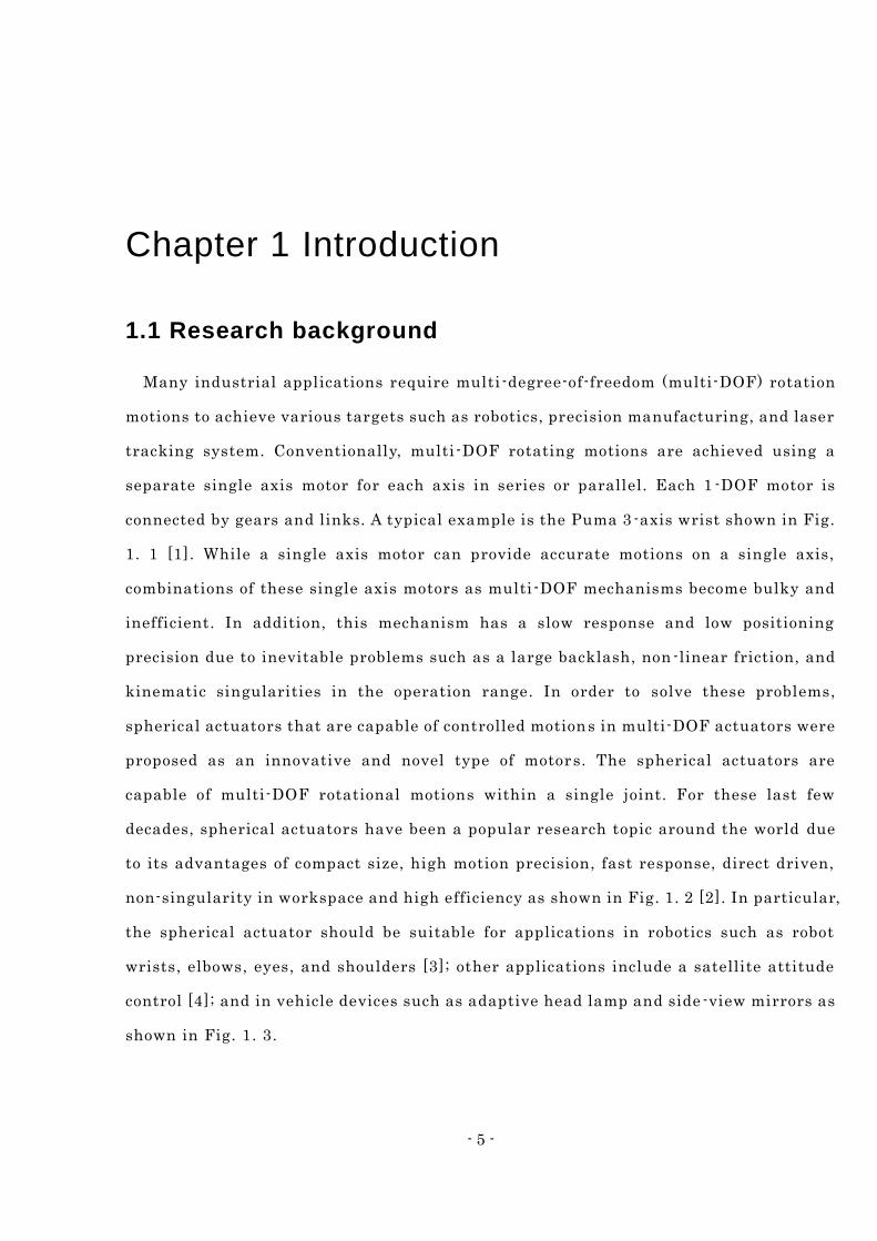
Many industrial applications require multi -degree-of-freedom (multi-DOF) rotation
motions to achieve various targets such as robotics, precision manufacturing, and laser
tracking system. Conventionally, multi -DOF rotating motions are achieved using a
separate single axis motor for each axis in series or parallel. Each 1 -DOF motor is
connected by gears and links. A typical example is the Puma 3 -axis wrist shown in Fig.
1. 1 [1]. While a single axis motor can provide accurate motions on a single axis,
combinations of these single axis motors as multi -DOF mechanisms become bulky and
inefficient. In addition, this mechanism has a slow response and low positioning
precision due to inevitable problems such as a large backlash, non -linear friction, and
kinematic singularities in the operation range. In order to solve these problems,
spherical actuators that are capable of controlled motions in multi-DOF actuators were
proposed as an innovative and novel type of motors. The spherical actuators are
capable of multi-DOF rotational motions within a single joint. For these last few
decades, spherical actuators have been a popular research topic around the world due
to its advantages of compact size, high motion precision, fast response, direct driven,
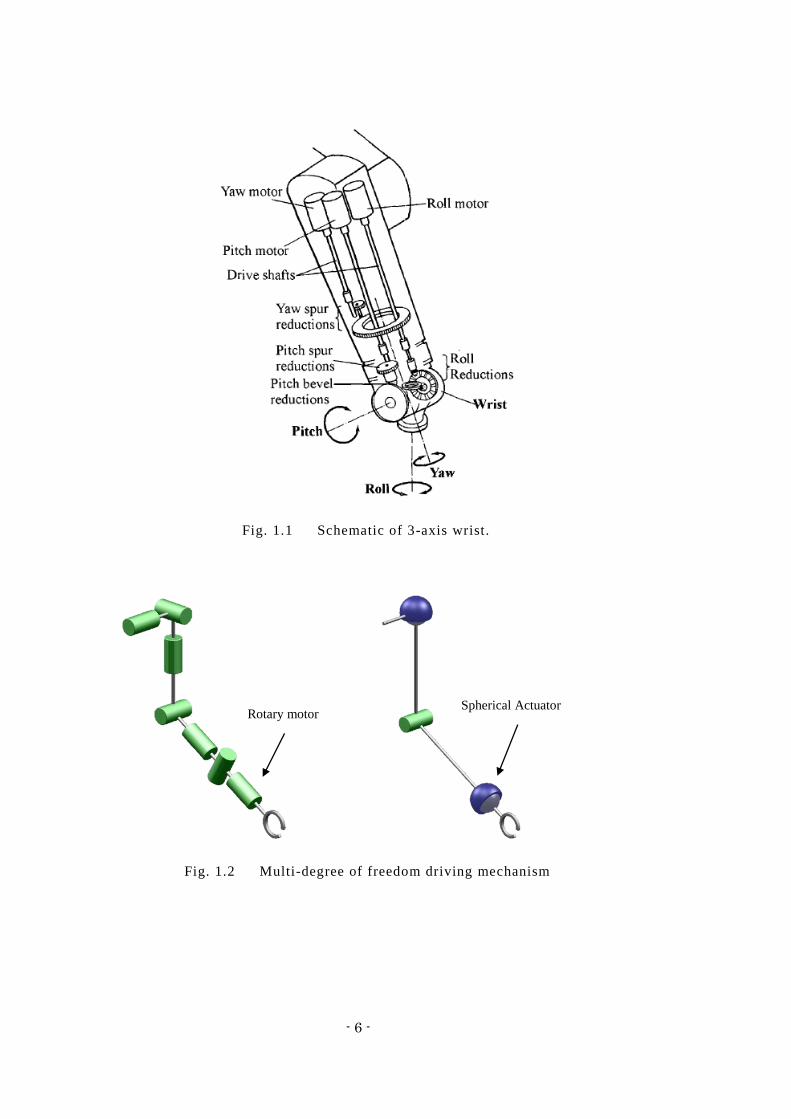
non-singularity in workspace and high efficiency as shown in Fig. 1. 2 [2]. In particular,
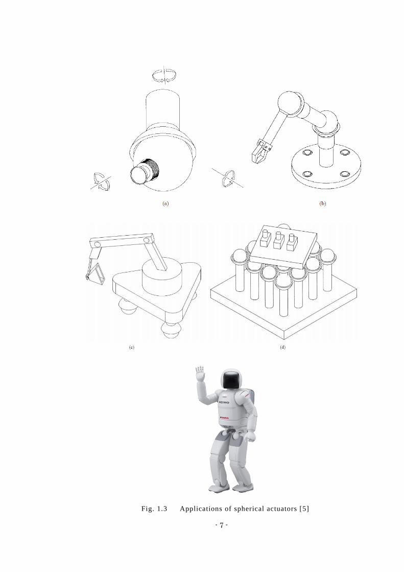
the spherical actuator should be suitable for applications in robotics such as robot
wrists, elbows, eyes, and shoulders [3]; other applications include a satellite attitude
control [4]; and in vehicle devices such as adaptive head lamp and side -view mirrors as
shown in Fig. 1. 3.
- 6 -
Fig. 1.1 Schematic of 3-axis wrist.
Fig. 1.2 Multi-degree of freedom driving mechanism
Rotary motorSpherical Actuator
- 7 -
Fig. 1.3 Applications of spherical actuators [5]
- 8 -
1.1.1 Spherical actuator technology
Spherical actuators take a number of forms including induction motors [6 -8],
reluctance motors [9-15], and ultrasonic motors [16-18]. Most spherical actuators are
based on the principle of electromagnetism. The three dimensional nature of the
electromagnetic field distribution in almost all of the foregoing spherical actuators
make their electromagnetic and dynamic behavior difficult to analyze, and this has
been a significant obstacle to their design optimization and servo application.
Closed-loop control systems for nonlinear electromagnetic spherical actuators
especially have difficulties due to a number of uncertainties involving system
identification and force/torque computation. As a result, the potential advantages of
employing spherical actuators have not been realized. Therefore, most developed
spherical actuators remain un-commercialized [15].
The greatest drawback associated with existing spherical actuators is that the
actuating mechanism is very complicated. Most spherical actuators are based on the
principle of electromagnetism. The three-dimensional nature of the electromagnetic
field distribution in nearly all spherical actuators makes their electromagnetic and
dynamic behavior difficult to analyze. This has been a significant obstacle which
prevents the optimization of their design and their use in servo application s.
1.2 Previous researches
Multi degree of freedom spherical actuators offer the potential for much improved
performance and have been the subject of research for several decades. Research into
multi-DOF spherical actuators has been in progress for several decades, and various
types of driving techniques have been proposed in the design of multi -DOF spherical
actuators.
- 9 -
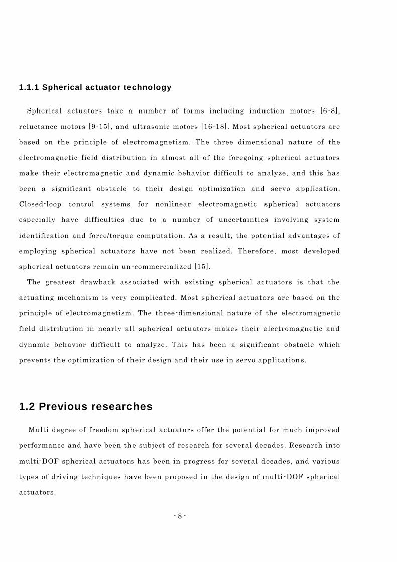
1.2.1 Induction spherical actuator
A spherical induction actuator was first proposed by Williams and Laithwaite et al
[22]. The actuation principle of the induction spherical actuator is that the magnetic
field generated by the stator windings induces a current on the rotor surface, which
causes the rotor to incline. Davey proposed a general analysis of both the fields and
resultant forces generic to the spherical induction actuator [6]. However, the actuator
had a mechanical complexity and inherent poor servo characteristics. Dehez developed
and analyzed a spherical induction actuator with magnetic teeth [8]. The stator
consists of five separate inductors as shown in Fig. 2. 1. In order to minimize the air
gap length and avoid friction, an aerostatic suspension of the rotor was used. The
results and the topology are interesting but still, no mention of control strategies are
provided to solve the low capability for a position control in the induction motor [23].
Traditionally, induction spherical actuators have not attracted commercial interests,
probably due to the relatively complex stator core and winding arrangement and the
inherently poor servo characteristics of induction motors.
Fig. 1. 4 Induction spherical actuator [8]
- 10 -
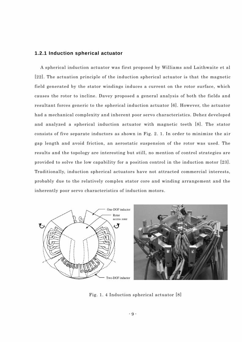
1.2.2 Ultrasonic spherical actuator
The ultrasonic spherical actuator is one of the most interesting spherical actuator
systems. Compared with an induction type driven by a mutual action of currents, the
ultrasonic spherical actuator lacks massive windings, and its simple structure makes
it lightweight and compact. The operating principle of the ultrasonic spherical
actuators is a frictional drive from the elliptical motion, in which a stator generates
vibration in the ultrasonic frequency range. The PZT elements are attached to the
stator and can produce expansion or contraction motions after being energized
positively or negatively as shown in Fig. 1. 5. The advantages of the ultrasonic
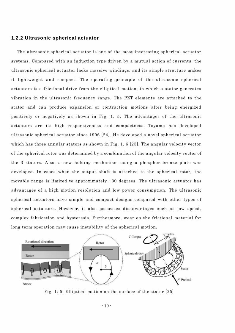
actuators are its high responsiveness and compactness. Toyama has developed
ultrasonic spherical actuator since 1996 [24]. He developed a novel spherical actuator
which has three annular stators as shown in Fig. 1. 6 [25]. The angular velocity vector
of the spherical rotor was determined by a combination of the angular velocity ve ctor of
the 3 stators. Also, a new holding mechanism using a phosphor bronze plate was
developed. In cases when the output shaft is attached to the spherical rotor, the
movable range is limited to approximately ±30 degrees. The ultrasonic actuator has
advantages of a high motion resolution and low power consumption. The ultrasonic
spherical actuators have simple and compact designs compared with other types of
spherical actuators. However, it also possesses disadvantages such as low speed,
complex fabrication and hysteresis. Furthermore, wear on the frictional material for
long term operation may cause instability of the spherical motion.
Fig. 1. 5. Elliptical motion on the surface of the stator [25]
- 11 -
Fig. 1. 6. Novel spherical ultrasonic actuator [25]
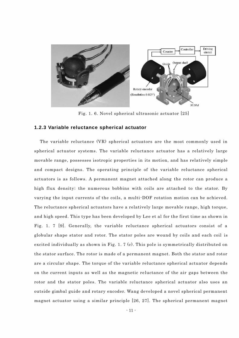
1.2.3 Variable reluctance spherical actuator
The variable reluctance (VR) spherical actuators are the most commonly used in
spherical actuator systems. The variable reluctance actuator has a relatively large
movable range, possesses isotropic properties in its motion, and has relatively simple
and compact designs. The operating principle of the variable reluctance spherical
actuators is as follows. A permanent magnet attached along the rotor can produce a
high flux density; the numerous bobbins with coils are attached to the stator. By
varying the input currents of the coils, a multi -DOF rotation motion can be achieved.
The reluctance spherical actuators have a relatively large movable range, high torque,
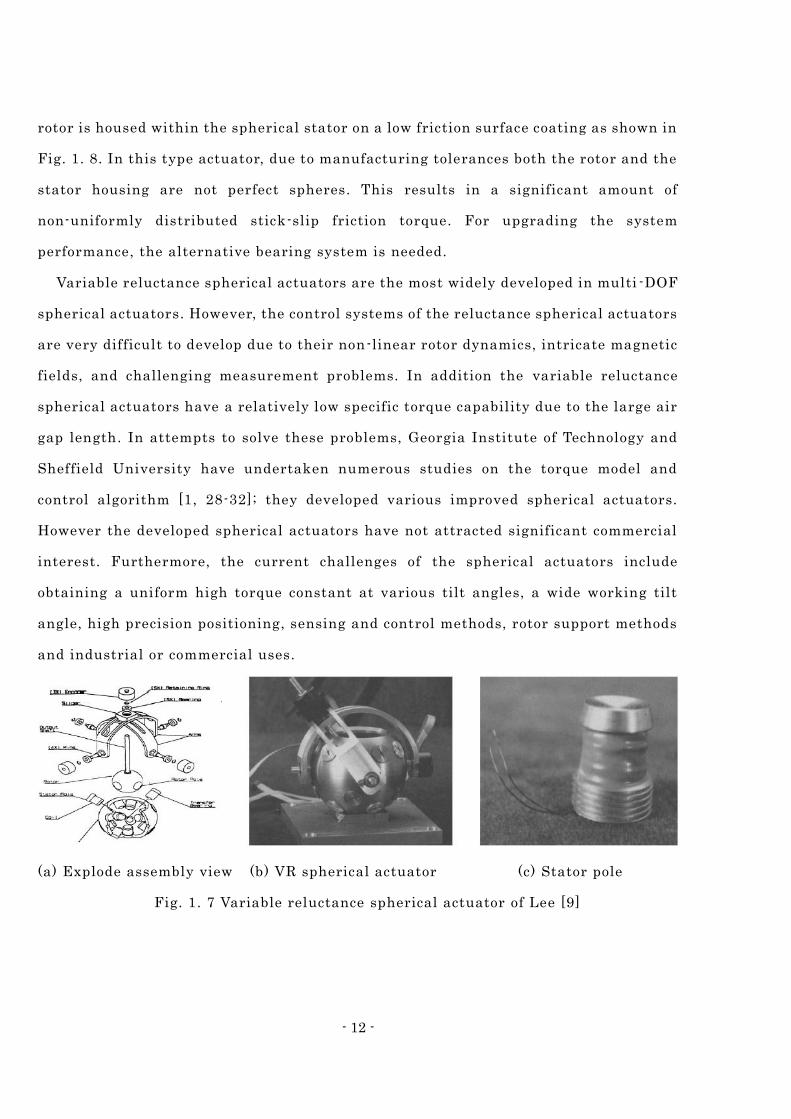
and high speed. This type has been developed by Lee et al for the first time as shown in
Fig. 1. 7 [9]. Generally, the variable reluctance spherical actuators consist of a
globular shape stator and rotor. The stator poles are wound by coils and each coil is
excited individually as shown in Fig. 1. 7 (c). This pole is symmetrically distributed on
the stator surface. The rotor is made of a permanent magnet. Both the stator and rotor
are a circular shape. The torque of the variable reluctance spherical actuator depends
on the current inputs as well as the magnetic re luctance of the air gaps between the
rotor and the stator poles. The variable reluctance spherical actuator also uses an
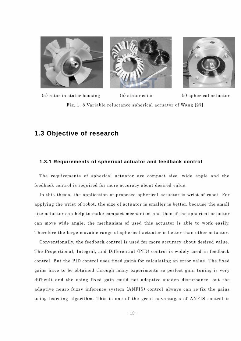
outside gimbal guide and rotary encoder. Wang developed a novel spherical permanent
magnet actuator using a similar principle [26, 27]. The spherical permanent magnet
- 12 -
rotor is housed within the spherical stator on a low friction surface coating as shown in
Fig. 1. 8. In this type actuator, due to manufacturing tolerances both the rotor and the
stator housing are not perfect spheres. This results in a significant amount of
non-uniformly distributed stick-slip friction torque. For upgrading the system
performance, the alternative bearing system is needed.
Variable reluctance spherical actuators are the most widely developed in multi -DOF
spherical actuators. However, the control systems of the reluctance spherical actuators
are very difficult to develop due to their non-linear rotor dynamics, intricate magnetic
fields, and challenging measurement problems. In addition the variable reluctance
spherical actuators have a relatively low specific torque capability due to the large air
gap length. In attempts to solve these problems, Georgia Institute of Technology and
Sheffield University have undertaken numerous studies on the torque model and
control algorithm [1, 28-32]; they developed various improved spherical actuators.
However the developed spherical actuators have not attracted significant commercial
interest. Furthermore, the current challenges of the spherical actuators include
obtaining a uniform high torque constant at various tilt angles, a wide working tilt
angle, high precision positioning, sensing and control methods, rotor support methods
and industrial or commercial uses.
(a) Explode assembly view (b) VR spherical actuator (c) Stator pole
Fig. 1. 7 Variable reluctance spherical actuator of Lee [9]
- 13 -
(a) rotor in stator housing (b) stator coils (c) spherical actuator
Fig. 1. 8 Variable reluctance spherical actuator of Wang [27]
1.3 Objective of research
1.3.1 Requirements of spherical actuator and feedback control
The requirements of spherical actuator are compact size, wide angle and the
feedback control is required for more accuracy about desired value.
In this thesis, the application of proposed spherical actuator is wrist of robot. For
applying the wrist of robot, the size of actuator is smaller is better, because the small
size actuator can help to make compact mechanism and then if the spherical actuator
can move wide angle, the mechanism of used this actuator is able to work easily.
Therefore the large movable range of spherical actuator is better than other actuator.
Conventionally, the feedback control is used for more accuracy about desired value.
The Proportional, Integral, and Differential (PID) control is widely used in feedback
control. But the PID control uses fixed gains for calculating an error value. The fixed
gains have to be obtained through many experiments so perfect gain tuning is very
difficult and the using fixed gain could not adaptive sudden disturbance, but the
adaptive neuro fuzzy inference system (ANFIS) control always can re-fix the gains
using learning algorithm. This is one of the great advantages of ANFIS control is
- 14 -
automating gain tuning.
1.3.2 Objective
A main objective of this thesis is to control a multi-DOF spherical actuator using
intelligent control method. The used intelligent control method in this thesis is ANFIS.
The multi-DOF spherical actuator is to propose, design a novel type of spherical
actuators in an application with a multi-DOF joint. The proposed spherical actuator is
capable of providing the three-DOF motions required for robotic wrists.
The aim of these control strategies is to obtain improved performances in terms of
disturbance rejection or parameter variation than obtained using conventional
algorithms. Because of integrate the best features of fuzzy logic and neural network.
Fuzzy logic control introduces a good tool to deal with complicated, non -linear and
ill-defined systems. Neural network has the powerful capability for learning,
adaptation, robustness and rapidity.
The key feature of the proposed spherical actuator is that it uses the same operating
principle with a VCM. Owing to the simple operating principle of the VCM, the
proposed spherical actuator has also a simple driving principle. The structure of VCM
principle is simpler than other synchronous motor principle. Therefore the structure of
proposed spherical actuator is more compact than previous spherical actuator.
1.3.3 Scope
This thesis mainly focuses on the intelligent control and the design of a novel
spherical actuator. The main points to consider in this thesis are as follows.
1. Intelligent control of the proposed spherical actuator
The proposed spherical actuator is controlled by an intelligent control. The final
output motion of the spherical actuator has coupled with 3-DOF rotational motions.
- 15 -
However, the three torque generation parts of the spherical actuator are totally
decoupled. Therefore, a control algorithm which enables input currents to decouple is
needed. The three degrees-of-freedom control method based on the system modeling is
described.
2. Proposal of a new spherical actuator
A novel spherical actuator is proposed. The operating principle of the new proposed
spherical actuator is based on a physics principle called the Lorentz force. It is easier
to control compared with previously used principles of actuating.
3. Modeling and analysis of the proposed spherical actuator
Firstly, in order to calculate the forces and torques acting on the rotor, the magnetic
flux distribution of the permanent magnet will be calculated at the air gap boundaries.
Secondly, forces and torques will be calculated by the Lorentz force principle. Thirdly,
the model will be verified using FEM tools. The verified analytical model will be used
for an optimal design process.
4. Design optimization of the proposed spherical actuator
Since the performance of the spherical actuator is heavily influenced by the design
parameters, an optimization procedure should be performed to obtain the best design
parameters. The dimensions of the permanent magnets, coils and steel yokes are
determined using design optimization frameworks in order to achieve a higher force
and torque.
1.4 Concept of the proposed spherical actuator
The proposed spherical actuator aims to overcome drawbacks of existing
development spherical actuators. The spherical actuators which were developed in the
- 16 -
past have complex manufacturing processes and non-linear rotor dynamics. Because of
these drawbacks, most of the developed spherical actuators are useless in industrial
applications. Therefore, my primary plan is to make a spherical actuator which is
useful in industrial application first. In addition, the proposed spherical actuator
should as much as possible have better performance than other spherical actuators. It
is impossible to solve the above problems using conventional actuation principles
(induction, ultrasonic, variable reluctance). Therefore, the actu ating method should be
changed. The new actuating method will be able to solve the above problems. The new
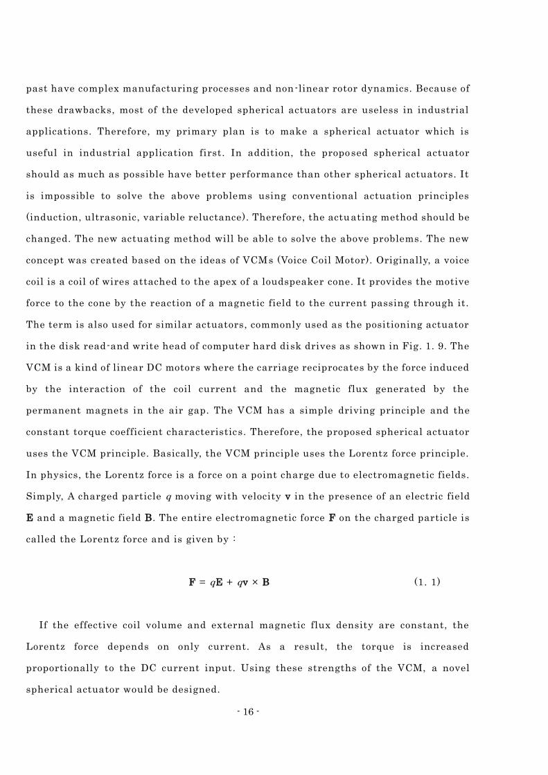
concept was created based on the ideas of VCMs (Voice Coil Motor). Originally, a voice
coil is a coil of wires attached to the apex of a loudspeaker cone. It provides the motive
force to the cone by the reaction of a magnetic field to the current passing through it.
The term is also used for similar actuators, commonly used as the positioning actuator
in the disk read-and write head of computer hard disk drives as shown in Fig. 1. 9. The
VCM is a kind of linear DC motors where the carriage reciprocates by the force induced
by the interaction of the coil current and the magnetic flux generated by the
permanent magnets in the air gap. The VCM has a simple driving principle and the
constant torque coefficient characteristics. Therefore, the proposed spherical actuator
uses the VCM principle. Basically, the VCM principle uses the Lorentz force principle.
In physics, the Lorentz force is a force on a point charge due to electromagnetic fields.
Simply, A charged particle q moving with velocity v in the presence of an electric field
E and a magnetic field B. The entire electromagnetic force F on the charged particle is
called the Lorentz force and is given by :
F = qE + qv × B (1. 1)
If the effective coil volume and external magnetic flux density are constant, the
Lorentz force depends on only current. As a result, the torque is increased
proportionally to the DC current input. Using these strengths of the VCM, a novel
spherical actuator would be designed.
- 17 -
Fig. 1. 9 HDD VCM
- 18 -
Spherical Actuator Chapter 2
2.1 Structure of actuator
2.1.1 Features of the proposed spherical actuator
Spherical actuators that have been developed in the past have complex
manufacturing processes and non-linear rotor dynamics. As a result of these
drawbacks, most of the developed spherical actuators are not useful in industrial
applications. Therefore, the first aim of the proposed spherical actuator is to be useful
in industrial applications. In addition, the proposed spherical actuator is designed to
have better performance than existing spherical actuators. For practical applications,
there is one significant design feature of the proposed spherical a ctuator: the moving
principle. The moving principle of the proposed spherical actuator was created based
on the ideas of the Voice Coil Motor (VCM). The VCM has a simple moving principle
and a constant torque coefficient characteristic. Using these strengt hs of the VCM, the
proposed spherical actuator can obtain uniform high torque, high resolution, and high
accuracy.
2.1.2 Design flow chart
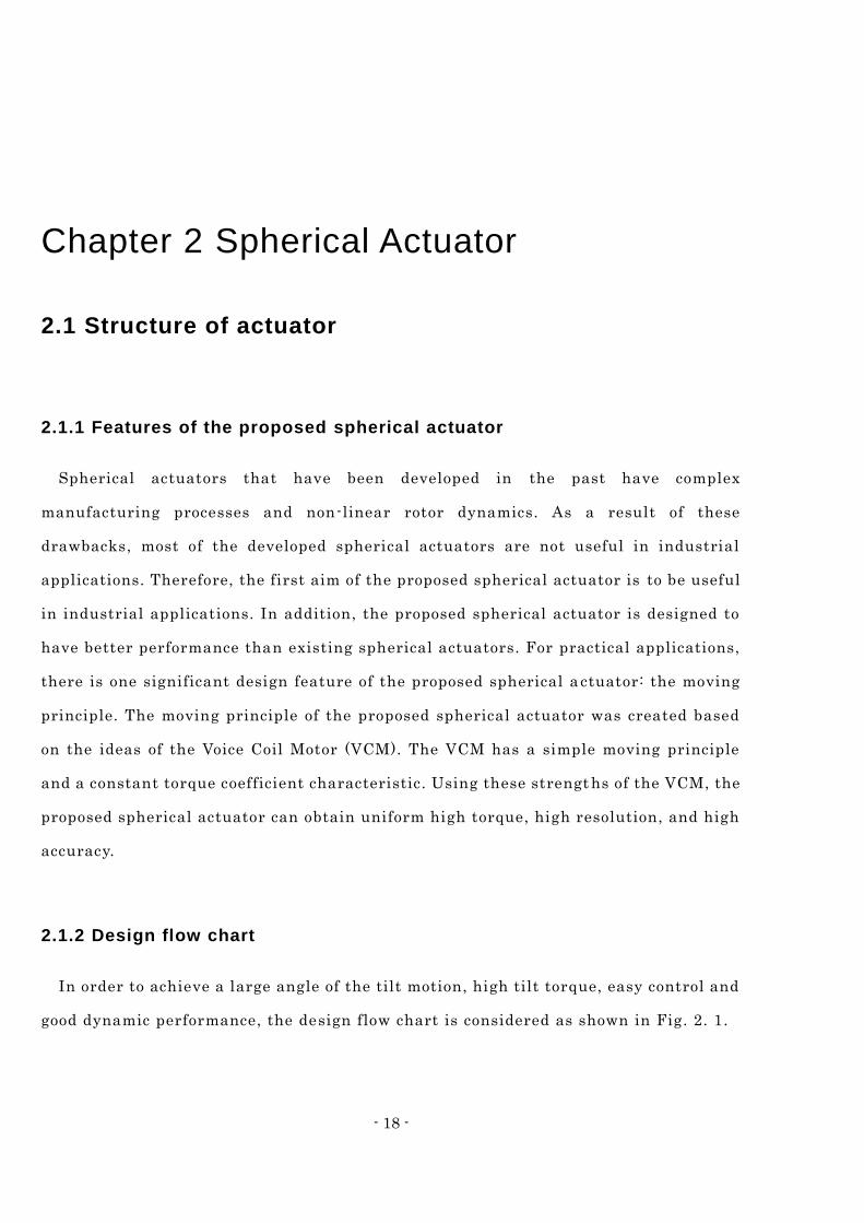
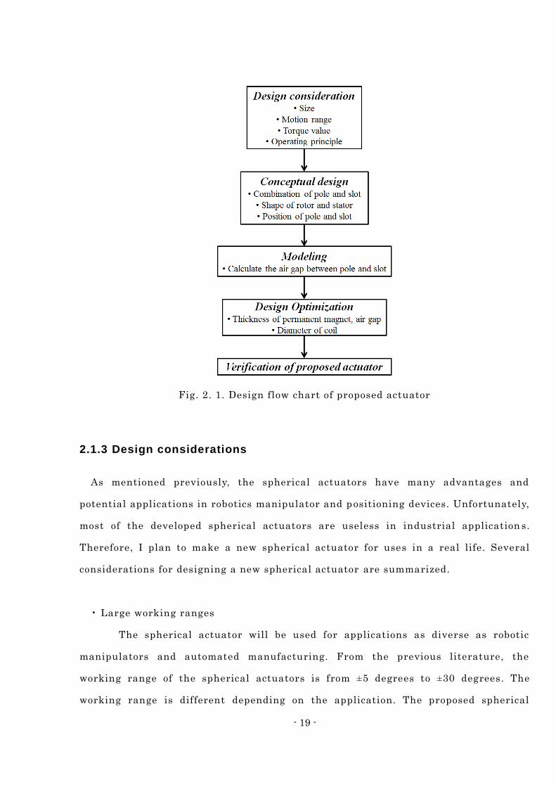
In order to achieve a large angle of the tilt motion, high tilt torque, easy control and
good dynamic performance, the design flow chart is considered as shown in Fig. 2. 1.
- 19 -
Fig. 2. 1. Design flow chart of proposed actuator
2.1.3 Design considerations
As mentioned previously, the spherical actuators have many advantages and
potential applications in robotics manipulator and positioning devices. Unfortunately,
most of the developed spherical actuators are useless in industrial application s.
Therefore, I plan to make a new spherical actuator for uses in a real life. Several
considerations for designing a new spherical actuator are summarized.
• Large working ranges
The spherical actuator will be used for applications as diverse as robotic
manipulators and automated manufacturing. From the previous literature, the
working range of the spherical actuators is from ±5 degrees to ±30 degrees. The
working range is different depending on the application. The proposed spherical
- 20 -
actuator will be applied to a wrist of a robot arm. Because the wrist of the robot arm
has an inherent angle of grapping, the working range of the proposed spherical
actuator is designed to be ±40 degrees. Considering that the existing spherical
actuator which has a ±40 working range did not have a constant torque constant at
whole tilt ranges. This working range specification is of the highest levels in the
development of the spherical actuators.
• Compact size
The size of the actuator is one of the main design considerations. In my case,
the outside diameter is 80 mm. In general, a bigger actuator has a higher torque. The
proposed spherical actuator has a small size compared to the other spherical actuators.
• High torque density
As mentioned earlier, the maximum torque does not mean anything. It is
natural that the bigger actuator has a higher torque. The torque density is more
important than the maximum torque. If the small actuator generates high torques, it is
the best one. The torque density of the proposed spherical actuator is 0.2 Nm/A. These
values were determined considering performances of literatures. Also it is large
enough for my applications.
• Constant torque in whole working range
Theoretically, the proposed spherical actuator has a constant torque in whole
working ranges. The most of the existing developed spherical actuators use a
variable-reluctance type. The variable-reluctance actuator makes only attraction
forces by inductions. The variable reluctance (VR) type actuator has nonlinear force s
to current and air gap length. However, the proposed spherical actuator uses a VCM
principle. The Lorentz force is independent of the rotor position if the magnetic flux
density is uniform.
- 21 -
• Manufacturing cost
The manufacturing cost is also an important design consideration. Considering
the manufacturing sizes of permanent magnets, coils and yokes, some components are
designed as discrete bodies. That should not affect the performance of the actuator. I
have tried to reduce the cost with an efficient design.
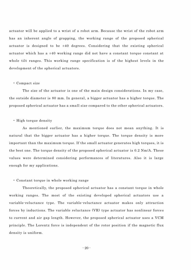
2.1.4 Conceptual design
The proposed spherical actuator consists of inner rotor, outer rotor and motion guide
as shown in Fig. 2. 2. The outer rotor and outer stator are used for tilt motions around
the X- and Y-axes.
Fig. 2. 2. Schematic diagram of whole model
- 22 -
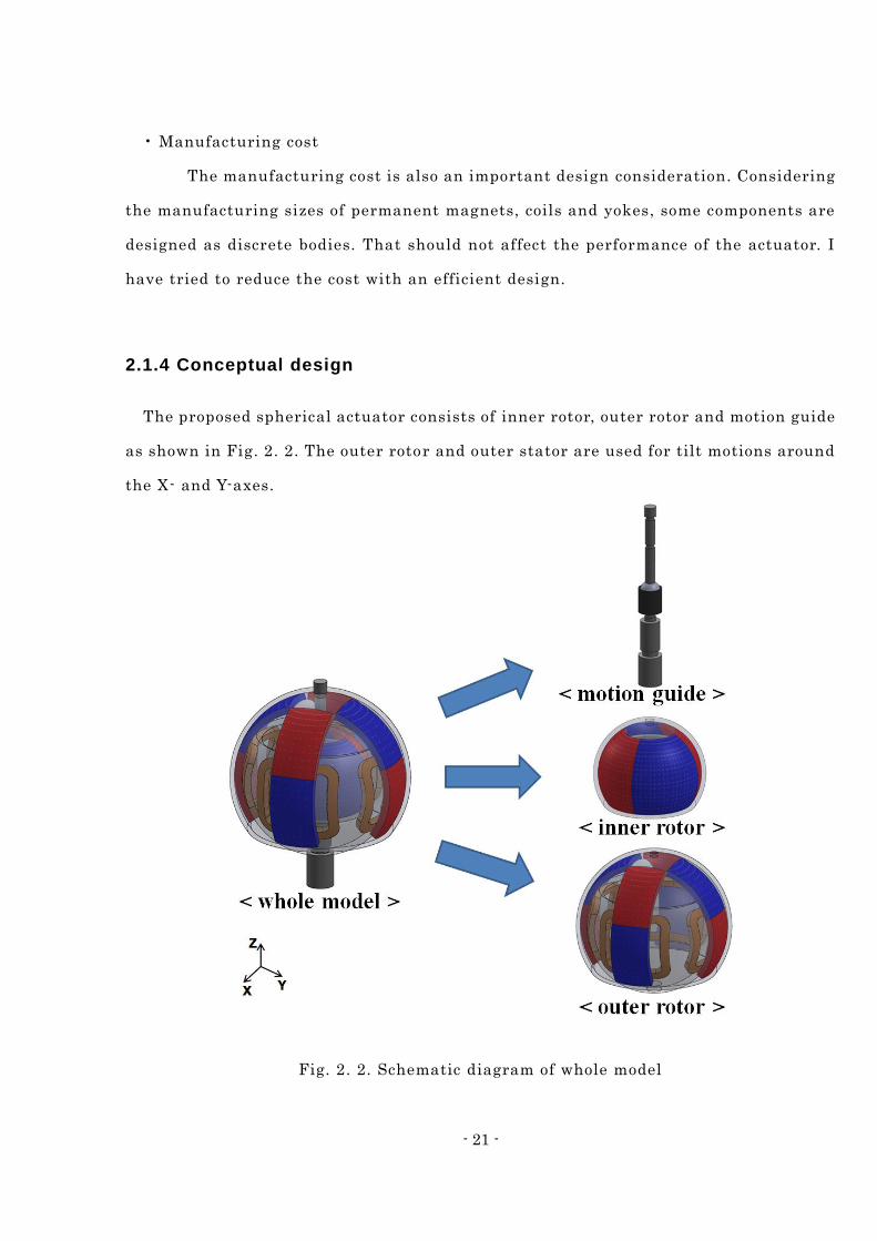
The outer rotor consists of 8-pole permanent magnets and 4 coils embedded into the
stator as shown in Fig. 2. 3. The inner rotor and inner stator are used for a rotation
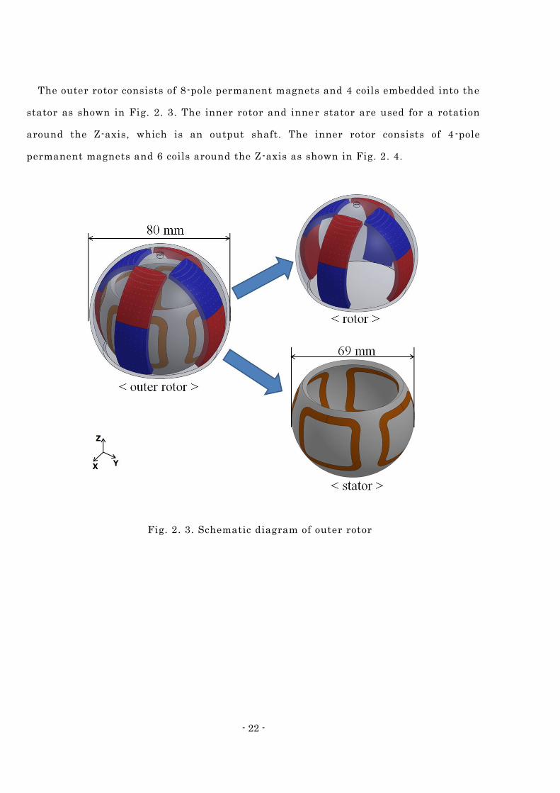
around the Z-axis, which is an output shaft. The inner rotor consists of 4 -pole
permanent magnets and 6 coils around the Z-axis as shown in Fig. 2. 4.
Fig. 2. 3. Schematic diagram of outer rotor
- 23 -
Fig. 2. 4. Schematic diagram of inner rotor
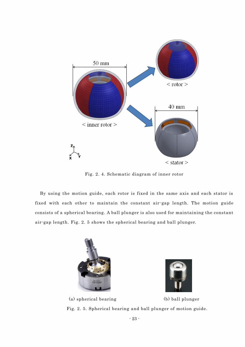
By using the motion guide, each rotor is fixed in the same axis and each stator is
fixed with each other to maintain the constant air-gap length. The motion guide
consists of a spherical bearing. A ball plunger is also used for maintaining the constant
air-gap length. Fig. 2. 5 shows the spherical bearing and ball plunger.
(a) spherical bearing (b) ball plunger
Fig. 2. 5. Spherical bearing and ball plunger of motion guide.
- 24 -
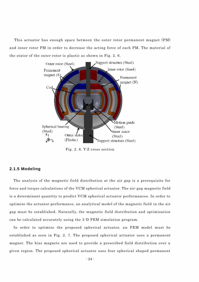
This actuator has enough space between the outer rotor permanent magnet (PM)
and inner rotor PM in order to decrease the acting force of each PM. The material of
the stator of the outer rotor is plastic as shown in Fig. 2. 6.
Fig. 2. 6. Y-Z cross section
2.1.5 Modeling
The analysis of the magnetic field distribution at the air gap is a prerequisite for
force and torque calculations of the VCM spherical actuator. The air-gap magnetic field
is a determinant quantity to predict VCM spherical actuator performances. In order to
optimize the actuator performance, an analytical model of the magnetic field in the air
gap must be established. Naturally, the magnetic field distribution and optimization
can be calculated accurately using the 3-D FEM simulation program.
In order to optimize the proposed spherical actuator, an FEM model must be
established as seen in Fig. 2. 7. The proposed spher ical actuator uses a permanent
magnet. The bias magnets are used to provide a prescribed field distribution over a
given region. The proposed spherical actuator uses four spherical shaped permanent
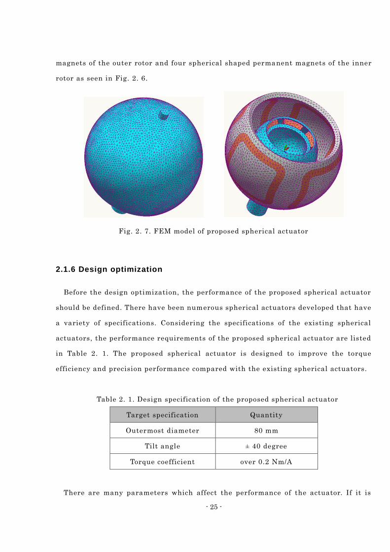
- 25 -
magnets of the outer rotor and four spherical shaped permanent magnets of the inner
rotor as seen in Fig. 2. 6.
Fig. 2. 7. FEM model of proposed spherical actuator
2.1.6 Design optimization
Before the design optimization, the performance of the proposed spherical actuator
should be defined. There have been numerous spherical actuators developed that have
a variety of specifications. Considering the specifications of the existing spherical
actuators, the performance requirements of the proposed spherical actuator are listed
in Table 2. 1. The proposed spherical actuator is designed to improve the torque
efficiency and precision performance compared with the existing spherical actuators.
Table 2. 1. Design specification of the proposed spherical actuator
Target specification Quantity
Outermost diameter 80 mm
Tilt angle ± 40 degree
Torque coefficient over 0.2 Nm/A
There are many parameters which affect the performance of the actuator. If it is
- 26 -
taking all these parameters into consideration, the optimal design process would be
very complicated and ineffective. Therefore, some parameters are fixed as constant
values.
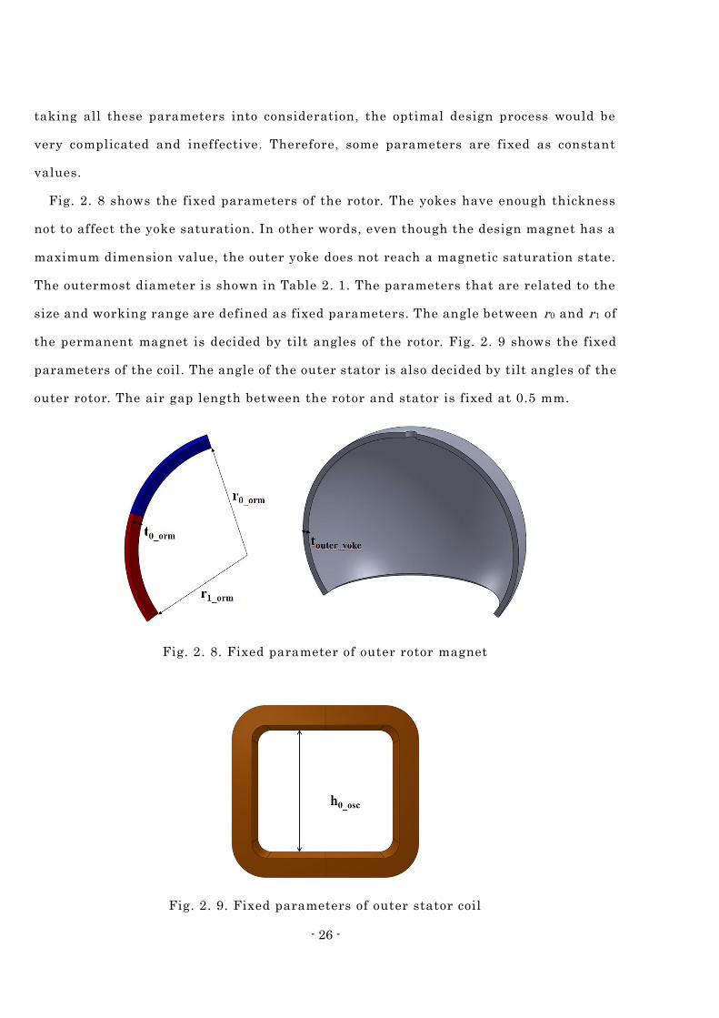
Fig. 2. 8 shows the fixed parameters of the rotor. The yokes have enough thickness
not to affect the yoke saturation. In other words, even though the design magnet has a
maximum dimension value, the outer yoke does not reach a magnetic saturation state.
The outermost diameter is shown in Table 2. 1. The parameters that are related to the
size and working range are defined as fixed parameters. The angle between r0 and r1 of
the permanent magnet is decided by tilt angles of the rotor. Fig. 2. 9 shows the fixed
parameters of the coil. The angle of the outer stator is also decided by tilt angles of the
outer rotor. The air gap length between the rotor and stator is fixed at 0.5 mm.
Fig. 2. 8. Fixed parameter of outer rotor magnet
Fig. 2. 9. Fixed parameters of outer stator coil
- 27 -
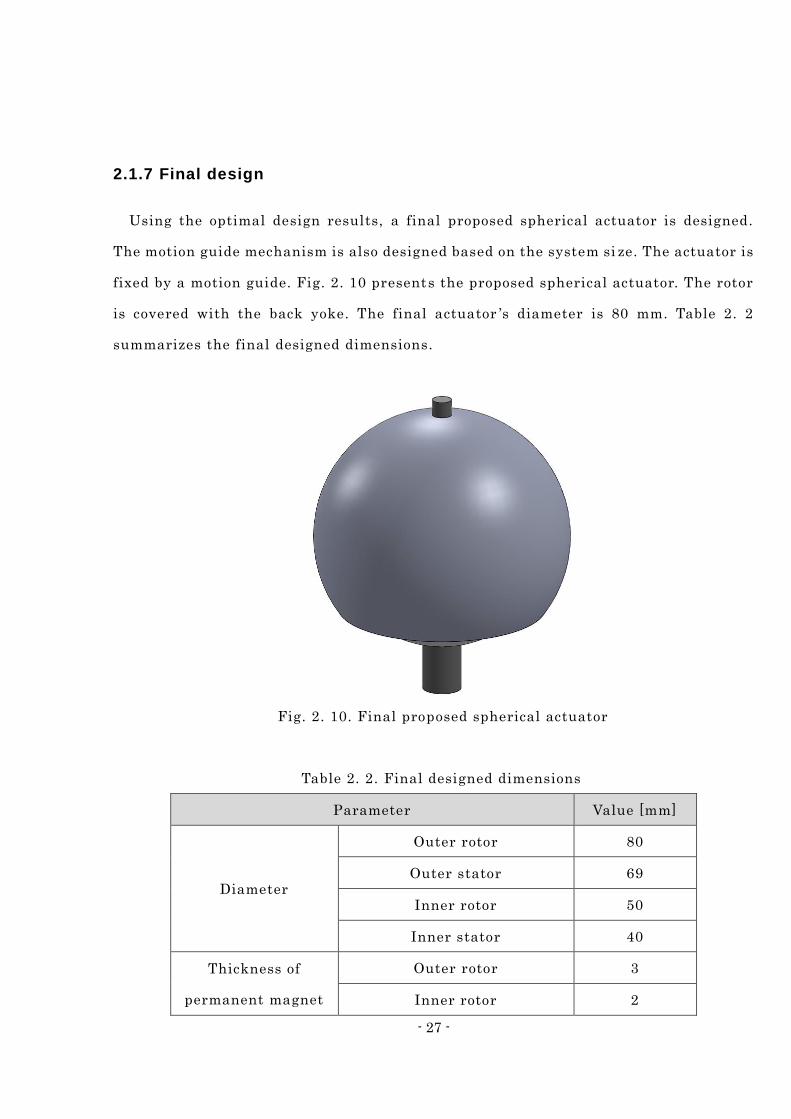
2.1.7 Final design
Using the optimal design results, a final proposed spherical actuator is designed.
The motion guide mechanism is also designed based on the system si ze. The actuator is
fixed by a motion guide. Fig. 2. 10 presents the proposed spherical actuator. The rotor
is covered with the back yoke. The final actuator ’s diameter is 80 mm. Table 2. 2
summarizes the final designed dimensions.
Fig. 2. 10. Final proposed spherical actuator
Table 2. 2. Final designed dimensions
Parameter Value [mm]
Diameter
Outer rotor 80
Outer stator 69
Inner rotor 50
Inner stator 40
Thickness of
permanent magnet
Outer rotor 3
Inner rotor 2
- 28 -
Width of permanent
magnet
Outer rotor 20
Inner rotor 24.33
Thickness of air-gap
Outer rotor Outer stator 0.5
Outer stator Inner rotor 6.5
Inner rotor Inner stator 1
Teeth of inner stator 0.1
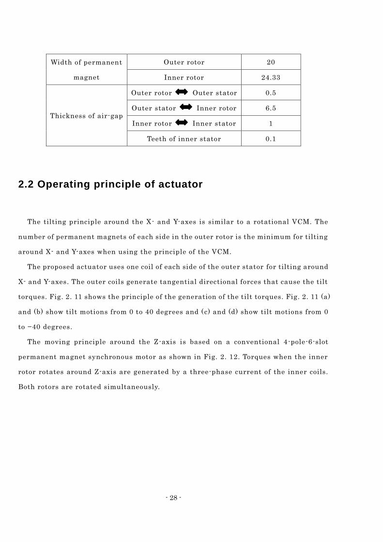
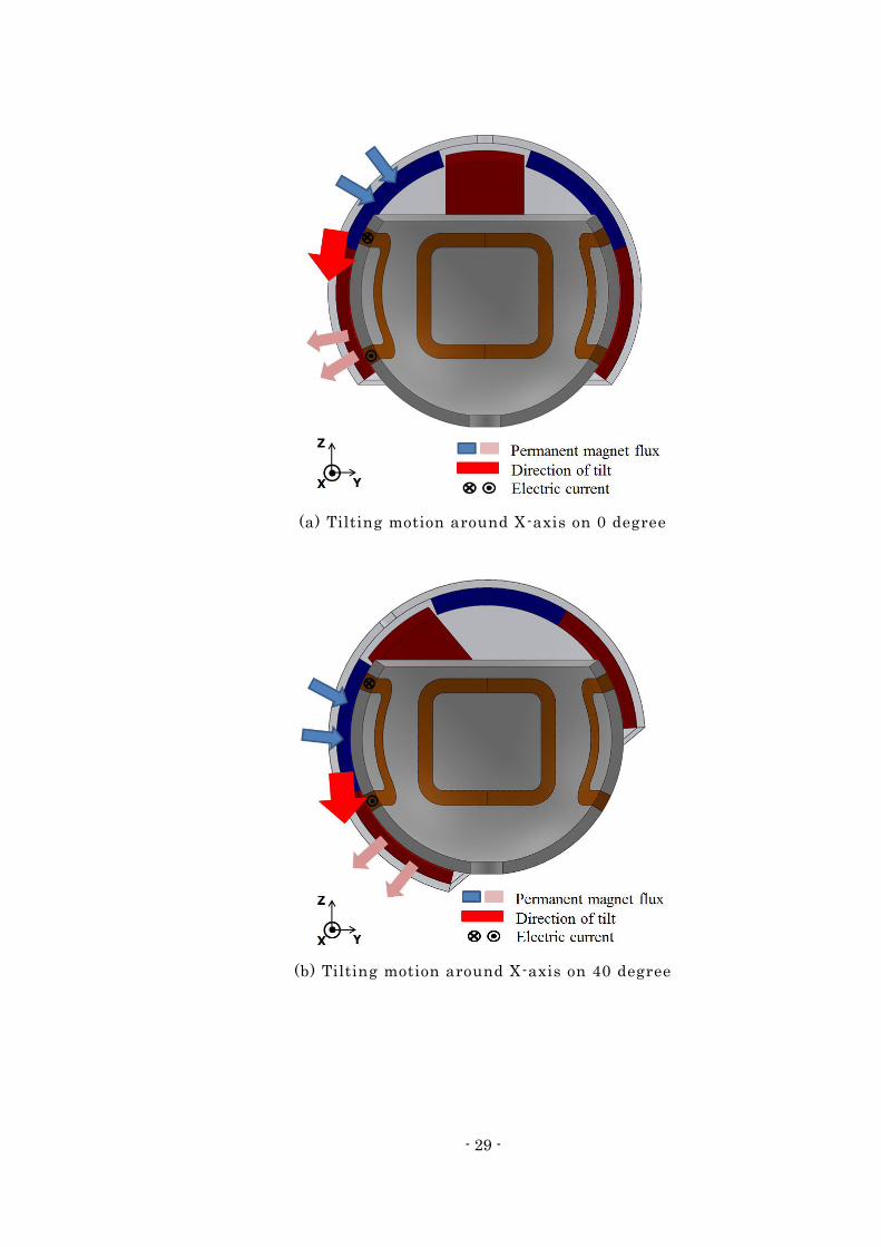
2.2 Operating principle of actuator
The tilting principle around the X- and Y-axes is similar to a rotational VCM. The
number of permanent magnets of each side in the outer rotor is the minimum for tilting
around X- and Y-axes when using the principle of the VCM.
The proposed actuator uses one coil of each side of the outer stator for tilting around
X- and Y-axes. The outer coils generate tangential directional forces that cause the tilt
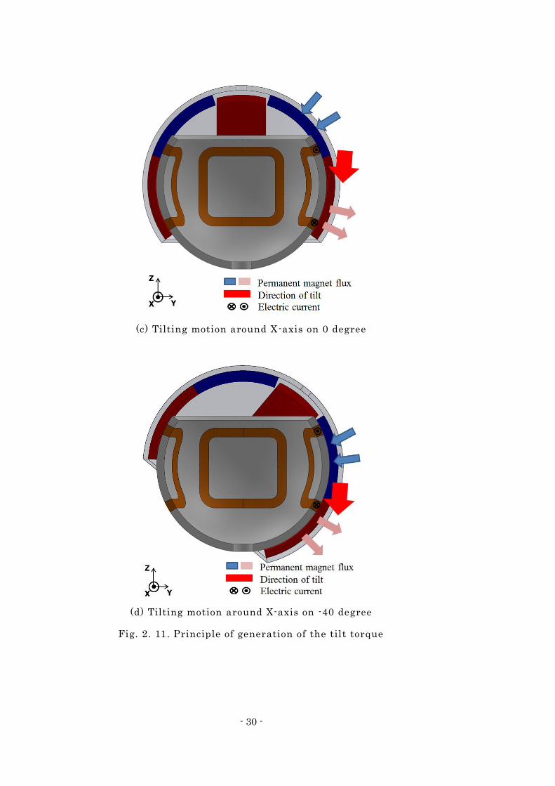
torques. Fig. 2. 11 shows the principle of the generation of the tilt torques. Fig. 2. 11 (a)
and (b) show tilt motions from 0 to 40 degrees and (c) and (d) show tilt motions from 0
to −40 degrees.
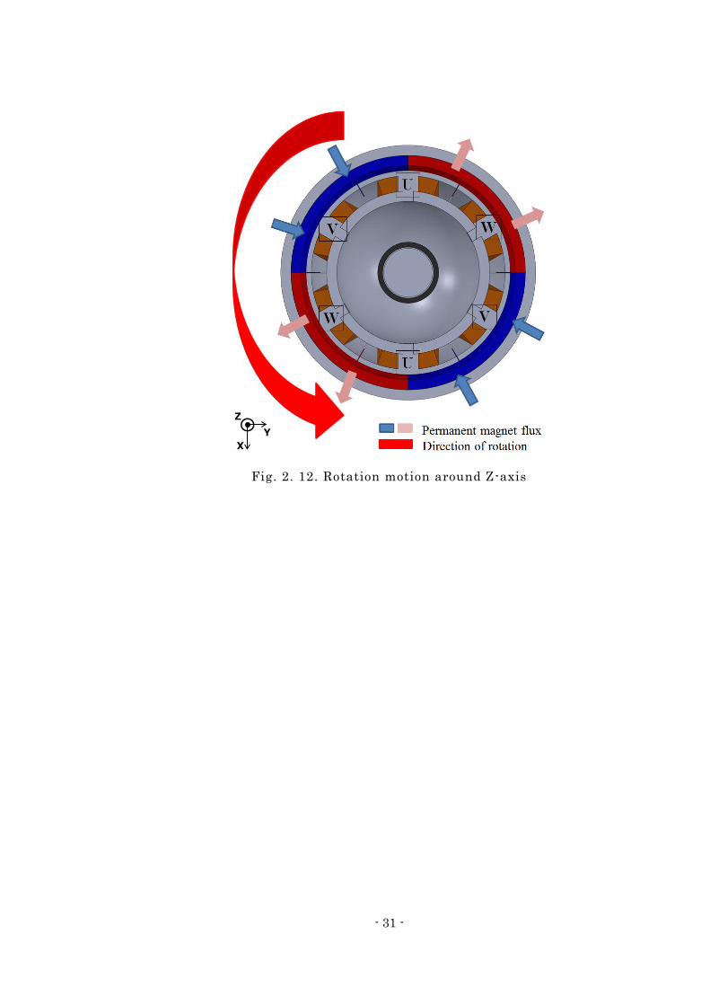
The moving principle around the Z-axis is based on a conventional 4-pole-6-slot
permanent magnet synchronous motor as shown in Fig. 2. 12. Torques when the inner
rotor rotates around Z-axis are generated by a three-phase current of the inner coils.
Both rotors are rotated simultaneously.
- 29 -
(a) Tilting motion around X-axis on 0 degree
(b) Tilting motion around X-axis on 40 degree
- 30 -
(c) Tilting motion around X-axis on 0 degree
(d) Tilting motion around X-axis on -40 degree
Fig. 2. 11. Principle of generation of the tilt torque
- 31 -
Fig. 2. 12. Rotation motion around Z-axis
- 32 -
Intelligent Control Method Chapter 3
Many feedback control algorithms such as PID (Proportional, Integral, and
Differential) control, fuzzy control and neural network control for actuator control
have been proposed. A PID controller is a control loop feedback mechanism controller
widely used in industrial control systems [33]. The PID controller calculates an error
value as the difference between a measured process variable and a desired value using
fixed gains which have to be obtained through many experiments, which is a
disadvantage. The adaptive neuro-fuzzy inference system (ANFIS), which was
developed in the early 1990s by Jang [34], combines the concepts of the fuzzy logic [35]
and neural networks [36, 37, 38] to form a hybrid intelligent system that enhances the
ability to automatically learn and adapt. The adaptive network is a network of nodes
and directional links. These networks learn the relationship between inputs and
outputs using learning rules such as a back propagation [39]. Therefore, a control
method is expected to produce more accurate results compared to other control
methods.
3.1 Adaptive Neuro-Fuzzy Inference System (ANFIS)
The fuzzy logic systems implement fuzzy sets to model uncertainty and approximate
knowledge reasoning, but the fuzzy logic architecture lacks learning rules. The neural
network systems strengthen adaptive learning rules for numerical sets to fit nonline ar
data, but the neural network feature lacks knowledge representation.
The neuro-fuzzy systems include intelligent systems which combine the main
- 33 -
features of both the fuzzy logic and the neural network systems to solve problems that
cannot be solved with desired performance by using either the fuzzy logic or the neural
network methodology alone [40]. The ANFIS is a fuzzy inference system embedded in
the framework of adaptive networks which provides the best optimization algorithm
for finding parameters to fit the given data. Based on human reasoning in the form of
fuzzy “IF-THEN” rules, the ANFIS develops the mapping of input and output data
pairs using a hybrid learning procedure. The hybrid learning procedure of the ANFIS
uses the backpropagation gradient descent algorithm in backward pass to tune the
premise parameters of membership functions and least squared error (LSE, also known
as Widrow-Hoff learning rule) [41] method in forward pass to adjust the consequent
parameters of output functions.
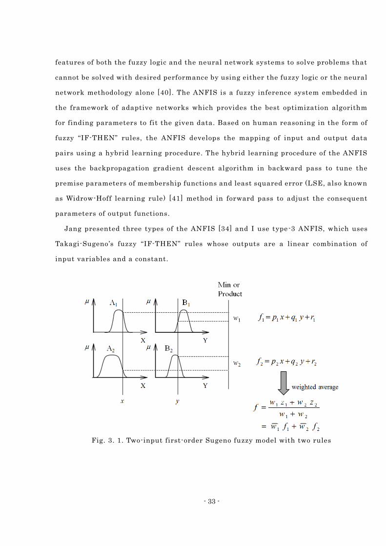
Jang presented three types of the ANFIS [34] and I use type-3 ANFIS, which uses
Takagi-Sugeno ’s fuzzy “IF-THEN” rules whose outputs are a linear combination of
input variables and a constant.
Fig. 3. 1. Two-input first-order Sugeno fuzzy model with two rules
- 34 -
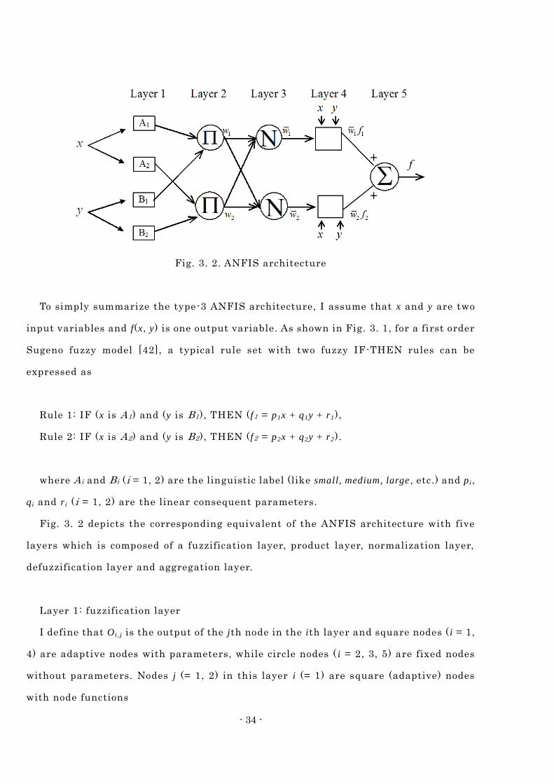
Fig. 3. 2. ANFIS architecture
To simply summarize the type-3 ANFIS architecture, I assume that x and y are two
input variables and f(x, y) is one output variable. As shown in Fig. 3. 1, for a first order
Sugeno fuzzy model [42], a typical rule set with two fuzzy IF-THEN rules can be
expressed as
Rule 1: IF (x is A1) and (y is B1), THEN ( f1 = p1x + q1y + r1),
Rule 2: IF (x is A2) and (y is B2), THEN ( f2 = p2x + q2y + r2).
where A i and B i (i = 1, 2) are the linguistic label (like small, medium, large , etc.) and p i,
q i and r i (i = 1, 2) are the linear consequent parameters.
Fig. 3. 2 depicts the corresponding equivalent of the ANFIS architecture with five
layers which is composed of a fuzzification layer, product layer, normalization layer,
defuzzification layer and aggregation layer.
Layer 1: fuzzification layer
I define that O i , j is the output of the jth node in the ith layer and square nodes ( i = 1,
4) are adaptive nodes with parameters, while circle nodes ( i = 2, 3, 5) are fixed nodes
without parameters. Nodes j (= 1, 2) in this layer i (= 1) are square (adaptive) nodes
with node functions
- 35 -
1, ( )jj AO x (3. 1)
1, ( )jj BO y
where the two crisp input x and y to nodes j are fuzzified through membership functions
(1) of the linguistic labels correlated to the node functions O1, j. The commonly used
membership functions are triangular, trapezoid, Gaussian-shaped and bell-shaped
membership functions.
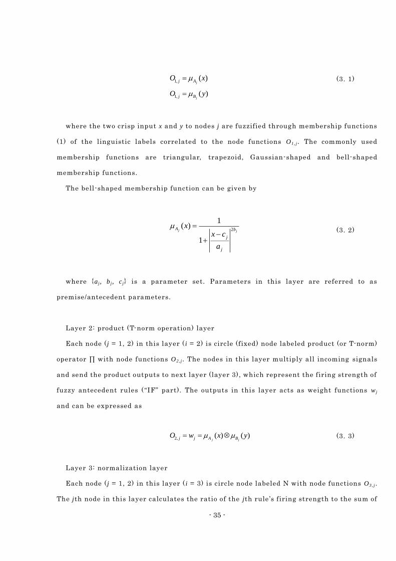
The bell-shaped membership function can be given by
2
1( )
1
j jA b
j
j
xx c
a
(3. 2)
where a j, b j, c j is a parameter set. Parameters in this layer are referred to as
premise/antecedent parameters.
Layer 2: product (T-norm operation) layer
Each node ( j = 1, 2) in this layer ( i = 2) is circle (fixed) node labeled product (or T-norm)
operator ∏ with node functions O2, j . The nodes in this layer multiply all incoming signals
and send the product outputs to next layer (layer 3), which represent the firing strength of
fuzzy antecedent rules (“IF” part). The outputs in this layer acts as weight functions w j
and can be expressed as
2, ( ) ( )j jj j A BO w x y (3. 3)
Layer 3: normalization layer
Each node ( j = 1, 2) in this layer ( i = 3) is circle node labeled N with node functions O3, j .
The jth node in this layer calculates the ratio of the jth rule ’s firing strength to the sum of
- 36 -
all rules ’ firing strengths. The outputs in this layer normalize the weight functions that
are transmitted from the previous product layer and the normalized weight functions
(firing strengths) jw can be written as
3,
1 2
jjj
wO w
w w
(3. 4)
Layer 4: defuzzification (consequent) layer
Each node ( j = 1, 2) in this layer ( i = 4) is square nodes with node functions O4, j . The jth
node in this layer defuzzifies the fuzzy consequent rule ( “THEN” part). The defuzzified
outputs in this layer are multiplied by normalized firing strengths based on the
formulation
4, ( )j j j j j j jO w f w p x q y r (3. 5)
where jw is the normalized firing strength from the previous layer (third layer) and p j,
q j, r j is a parameter set. The parameters in this layer will be referred to as consequent
parameters.
Layer 5: aggregation (summation) layer
The single node in this layer ( i = 5) is a fixed node labeled ∑ with a node function O5, 1,
which computes the overall output as a summation of all incoming signals and can be
expressed as
5, 1
j jj
j j
j jj
w fO w f
w
(3. 6)
In the ANFIS architecture, there are adaptive nodes in the first layer and fourth layer.
To optimize this parameter needs learning algorithm. There are two learning algorithms
- 37 -
developed by Jang et al. [43], namely hybrid learning algorithm and backpropagation. The
hybrid learning algorithm is an algorithm that combines of two methods which is
least-squares and gradient descent. There are two steps in this method, forward and the
backward movements. In the forward movement, the network input will propagate forward
until the fourth layer, where the consequent parameters will be identified by using a
least-square method. In the backwards movement step, after calculating the error, the
error signal will propagate backward and the premise parameters will be fixed by using a
gradient-descent method. In this thesis, hybrid learning algorithm is selected for training
the ANFIS model.
In the determining network topology of ANFIS, refer to the problem to be solved, the
number of input membership function and the number of rule is determined principal
component analysis with initial data. In order to determine the optimal numbers of
membership function and the numbers of rule, several numbers of clustering ar ound 2 to 3
are evaluated. After several numbers of clustering are evaluated, each model adopts an
appropriate number of rules.
- 38 -
Verification Chapter 4
In this chapter, the manufactured 2-DOF spherical actuator will be controlled using
ANFIS and 3-DOF spherical actuator will be analyzed using ANFIS. The 3-DOF
spherical actuator modeling results with the optimal design process in chapter 2 are
analytically verified.
4.1 Experiments of 2-DOF spherical actuator with
intelligent control
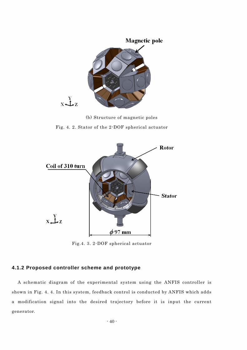
4.1.1 Basic structure of 2-DOF spherical actuator
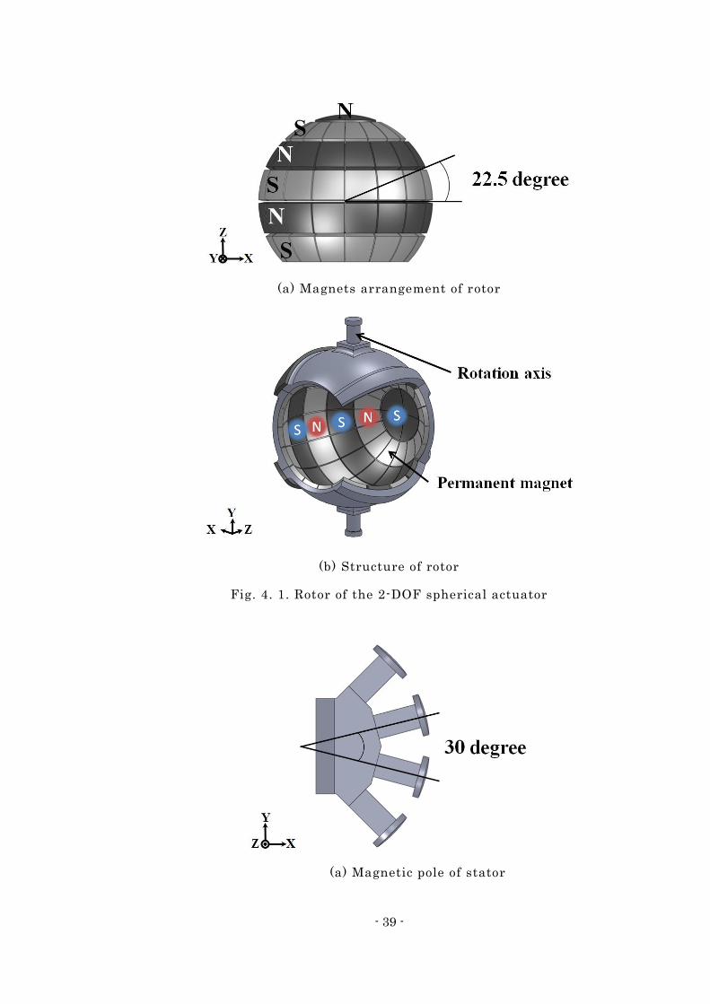
The 2-DOF spherical actuator is composed of a stator and rotor as shown in Fig. 4. 1
and 4. 2. In the rotor, six rows of identically polarized N and S pole shell -shaped
permanent magnets are arranged around the Z-axis. On the other hand, the stator has
24 teeth with 310 turn concentrated windings on each pole. They are also arrayed
around the Z-axis at even intervals as shown in Fig. 4. 3. This structure makes it
similar to controlling a 16-pole-12-slot synchronous motor the X- and Y-axes.
- 39 -
(a) Magnets arrangement of rotor
(b) Structure of rotor
Fig. 4. 1. Rotor of the 2-DOF spherical actuator
(a) Magnetic pole of stator
- 40 -
(b) Structure of magnetic poles
Fig. 4. 2. Stator of the 2-DOF spherical actuator
Fig.4. 3. 2-DOF spherical actuator
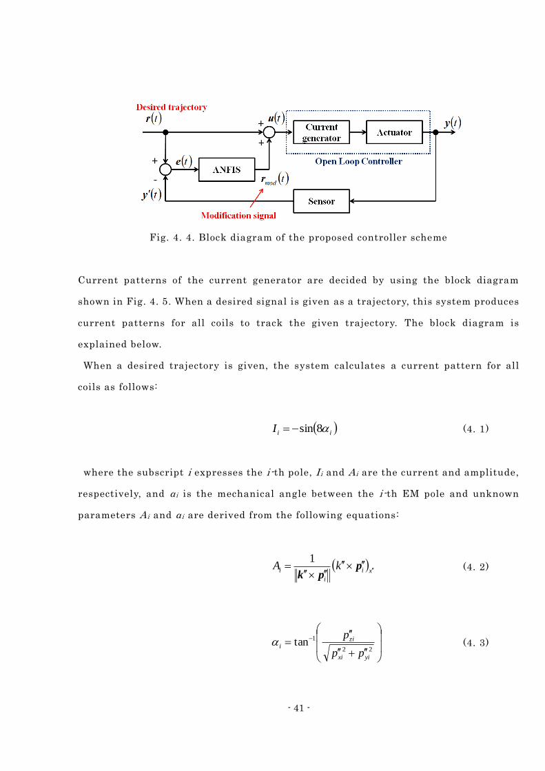
4.1.2 Proposed controller scheme and prototype
A schematic diagram of the experimental system using the ANFIS controller is
shown in Fig. 4. 4. In this system, feedback control is conducted by ANFIS which adds
a modification signal into the desired trajectory before it is input the current
generator.
- 41 -
Fig. 4. 4. Block diagram of the proposed controller scheme
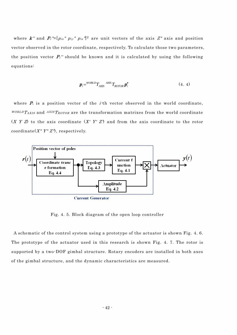
Current patterns of the current generator are decided by using the block diagram
shown in Fig. 4. 5. When a desired signal is given as a trajectory, this system produces
current patterns for all coils to track the given trajectory. The block diagram is
explained below.
When a desired trajectory is given, the system calculates a current pattern for all
coils as follows:
iiI 8sin (4. 1)
where the subscript i expresses the i-th pole, I i and A i are the current and amplitude,
respectively, and α i is the mechanical angle between the i-th EM pole and unknown
parameters A i and α i are derived from the following equations:
xi
i
i kA
ppk
1 (4. 2)
22
1tan
yixi
zii
pp
p (4. 3)
- 42 -
where k'' and P i ' '=[p ix" p iy" p iz"]T are unit vectors of the axis Z" axis and position
vector observed in the rotor coordinate, respectively. To calculate those two parameters,
the position vector P i ' ' should be known and it is calculated by using the following
equations:
iROTOR
AXIS
AXIS
WORLD
i TT pp (4. 4)
where P i is a position vector of the i-th vector observed in the world coordinate,
WORLDTAXIS and AXISTROTOR are the transformation matrixes from the world coordinate
(X Y Z) to the axis coordinate (X' Y' Z') and from the axis coordinate to the rotor
coordinate(X" Y" Z"), respectively.
Fig. 4. 5. Block diagram of the open loop controller
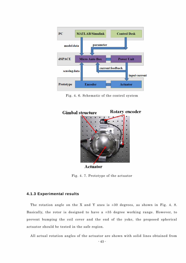
A schematic of the control system using a prototype of the actuator is shown Fig. 4. 6.
The prototype of the actuator used in this research is shown Fig. 4. 7. The rotor is
supported by a two-DOF gimbal structure. Rotary encoders are installed in both axes
of the gimbal structure, and the dynamic characteristics are measured.
- 43 -
Fig. 4. 6. Schematic of the control system
Fig. 4. 7. Prototype of the actuator
4.1.3 Experimental results
The rotation angle on the X and Y axes is ±30 degrees, as shown in Fig. 4. 8.
Basically, the rotor is designed to have a ±35 degree working range. However, to
prevent bumping the coil cover and the end of the yoke, the proposed spherical
actuator should be tested in the safe region.
All actual rotation angles of the actuator are shown with solid lines obtained from
- 44 -
the two rotary encoders of the gimbal structure.
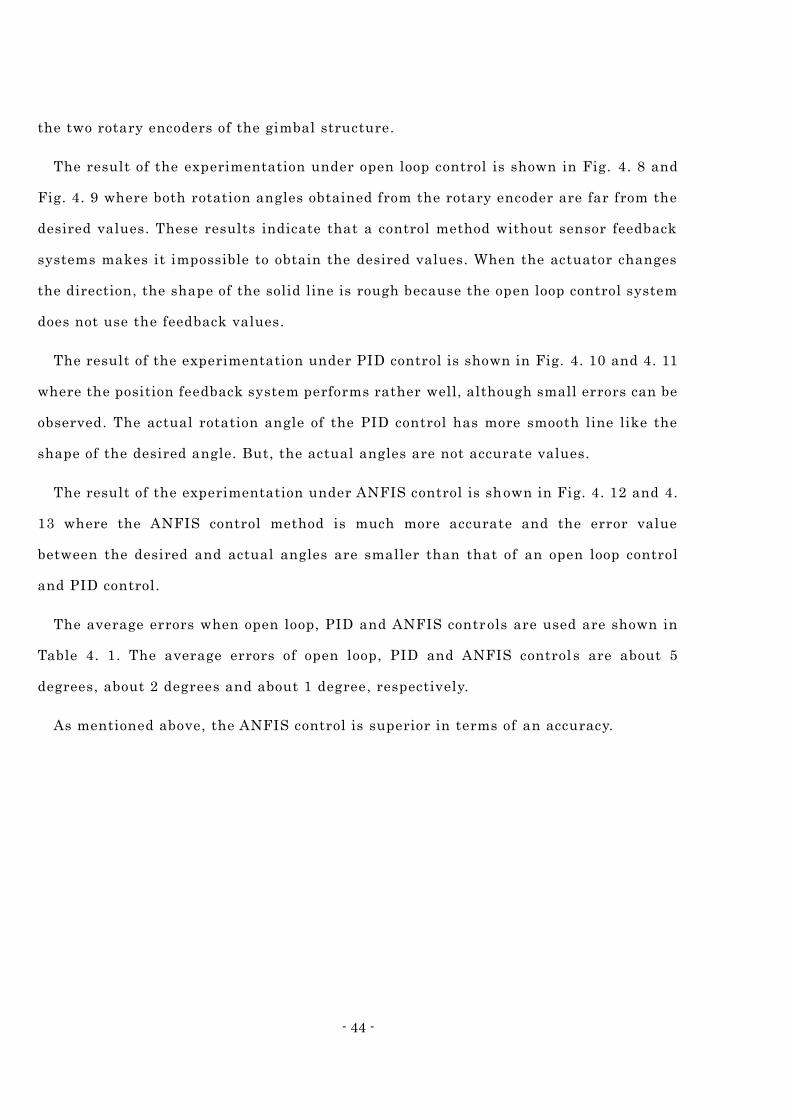
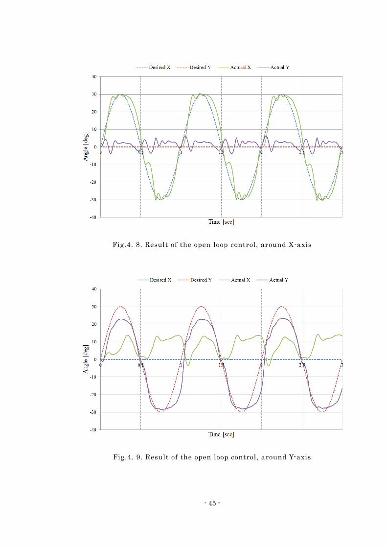
The result of the experimentation under open loop control is shown in Fig. 4. 8 and
Fig. 4. 9 where both rotation angles obtained from the rotary encoder are far from the
desired values. These results indicate that a control method without sensor feedback
systems makes it impossible to obtain the desired values. When the actuator changes
the direction, the shape of the solid line is rough because the open loop control system
does not use the feedback values.
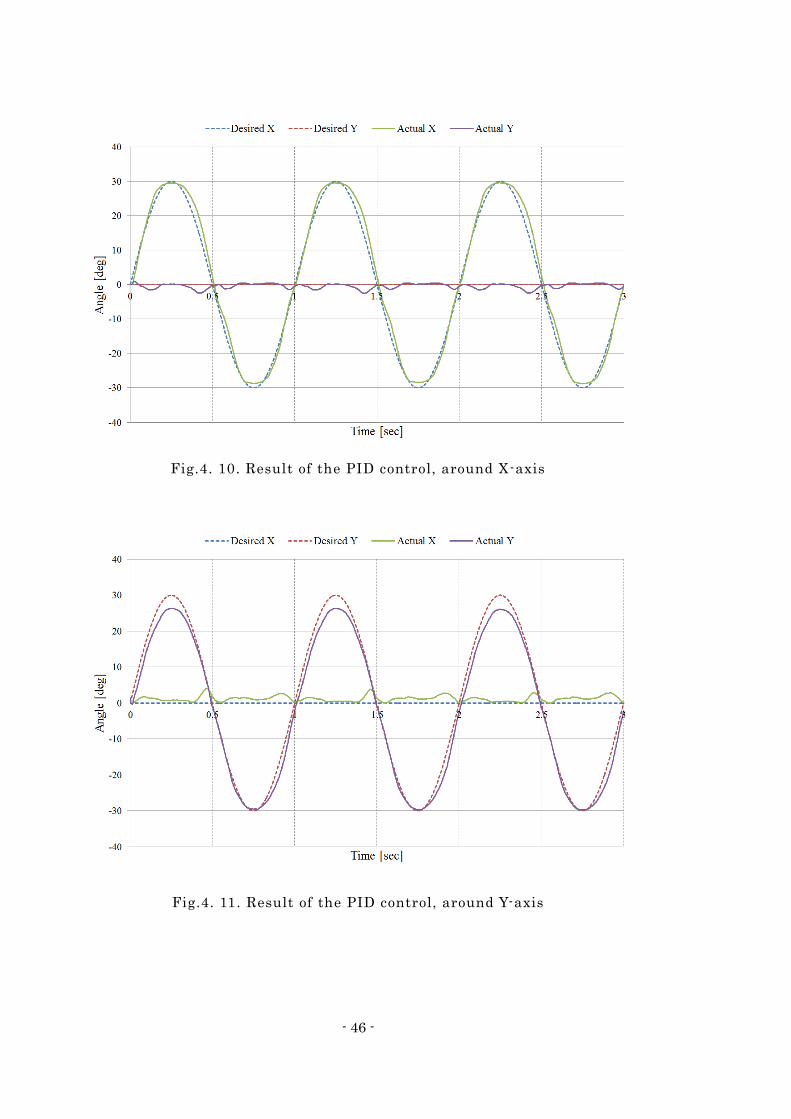
The result of the experimentation under PID control is shown in Fig. 4. 10 and 4. 11
where the position feedback system performs rather well, although small errors can be
observed. The actual rotation angle of the PID control has more smooth line like the
shape of the desired angle. But, the actual angles are not accurate values.
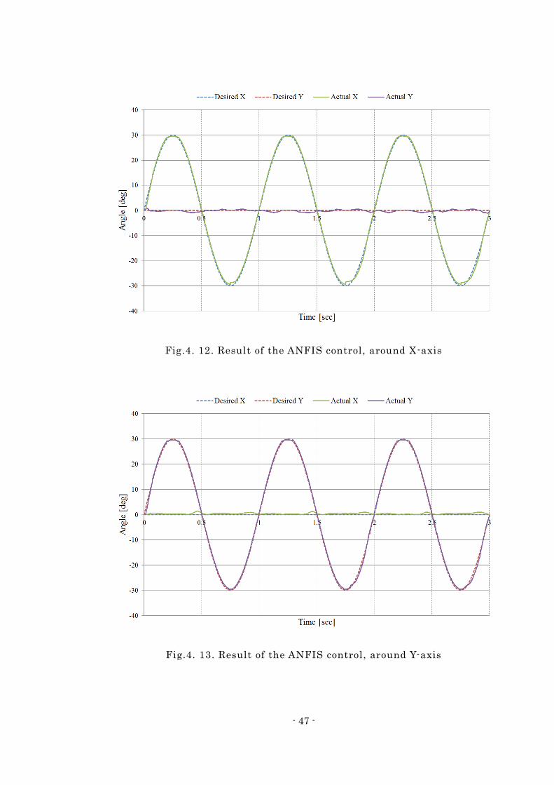
The result of the experimentation under ANFIS control is shown in Fig. 4. 12 and 4.
13 where the ANFIS control method is much more accurate and the error value
between the desired and actual angles are smaller than that of an open loop control
and PID control.
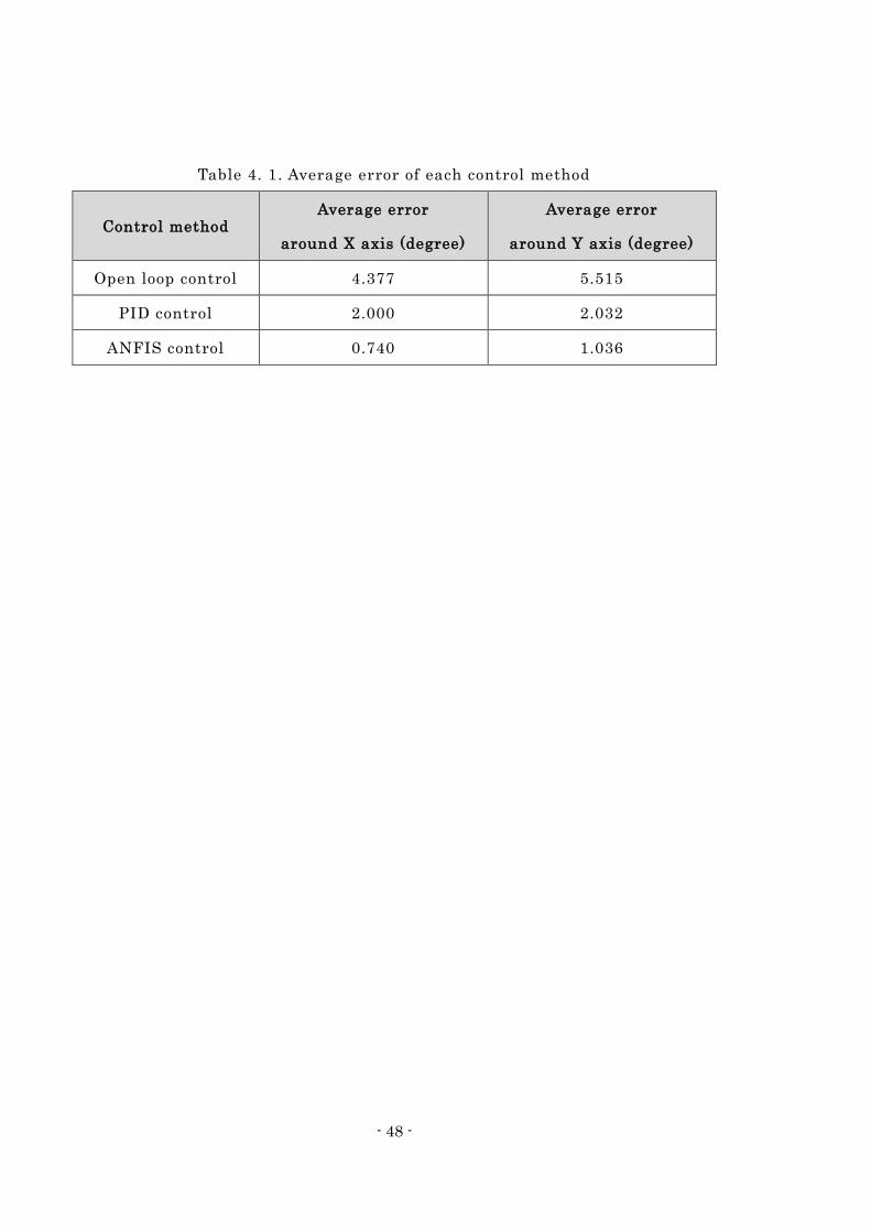
The average errors when open loop, PID and ANFIS controls are used are shown in
Table 4. 1. The average errors of open loop, PID and ANFIS control s are about 5
degrees, about 2 degrees and about 1 degree, respectively.
As mentioned above, the ANFIS control is superior in terms of an accuracy.
- 45 -
Fig.4. 8. Result of the open loop control, around X-axis
Fig.4. 9. Result of the open loop control, around Y-axis
- 46 -
Fig.4. 10. Result of the PID control, around X-axis
Fig.4. 11. Result of the PID control, around Y-axis
- 47 -
Fig.4. 12. Result of the ANFIS control, around X-axis
Fig.4. 13. Result of the ANFIS control, around Y-axis
- 48 -
Table 4. 1. Average error of each control method
Control method Average error
around X axis (degree)
Average error
around Y axis (degree)
Open loop control 4.377 5.515
PID control 2.000 2.032
ANFIS control 0.740 1.036
- 49 -
4.2 Analyzed results of 3-DOF spherical actuator with
intelligent control
4.2.1 Characteristic analysis
4.2.1.1 Analysis method
An electromagnetic field analysis using 3 -D finite element method (FEM) is
conducted to determine the static torque characteristics and the dynamic operating
characteristics of the proposed actuator. These characteristics of the actuator are
computed by employing the Ω-method given in (4. 5) through (4. 7).
(4. 5)
(4. 6)
(4. 7)
where μ is the permeabil i ty , T0 and Tm are the current vector potential derived fr
om the forced current density J0 and equivalent magnetization current density Jm ,
respect ively , as given in (4. 6) , and Ω is the magnetic scalar potential as is given b
y (4. 7) . H is the magnetic f ie ld intensity . Equation ( 4. 5) is computed by using Gale
rkin ’s method and then the magnetic force is determined by using Maxwell ’ s stress
method. The dynamic characterist i cs are computed in each axis combined with the
motion equation is given as fo l lows.
(i = x, y, z) (4 . 8)
0 graddiv 0 TTm
00 rot
rot
TJ
TJ mm
grad0TTH m
misi
i
ii
i
ii TT
dt
dD
dt
dI
2
2
- 50 -
where I i is the moment o f inert ia of the rotor, D i is the viscous damping coe ff i c ie
nt , Ɵ i is the rotation angle of the rotor, T s i and T m i are the fri ct ion torque and the
torque act ing on the rotor , respect ively , and i is the rotation axis of the rotor.
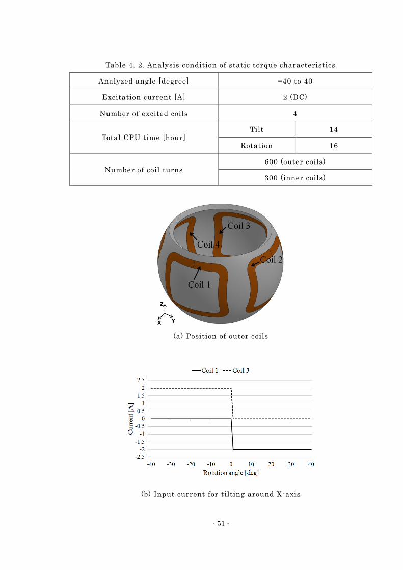
4.2.1.2 Static torque characteristic analysis
Static torque characteristics analyses were conducted under the following four
conditions. In addition to uniaxial motions, the characteristics of multi -axial motions
were analyzed to see how a motion around one axis affects a motion around another.
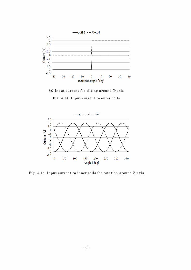
Fig. 4. 14 shows the position and the input current of the outer coils for tilting motions
around the X- and Y-axes. Fig. 4. 15 shows the input current to the inner coils to rotate
around the Z-axis. The 3-D finite element mesh model used in these analyses is shown
in Fig. 2. 7, and Table 4. 2 shows the analysis conditions to compute the static torque
characteristics.
The analyzed angular ranges of these analyses are from −40 to 40 degrees for a tilt
motion and from 0 to 90 degrees for a rotation motion. Each coil is excited by a 2-A DC
during tilt motion, and the inner coils are excited by 2-A 3-phase AC during rotation
motion. In addition to the output torque characteristics, the cogging torque
characteristics are also computed in each analysis (dashed lines in each figure). The
results of the analyses are shown in Figs. 4. 17-22.
- 51 -
Table 4. 2. Analysis condition of static torque characteristics
Analyzed angle [degree] −40 to 40
Excitation current [A] 2 (DC)
Number of excited coils 4
Total CPU time [hour] Tilt 14
Rotation 16
Number of coil turns 600 (outer coils)
300 (inner coils)
(a) Position of outer coils
(b) Input current for tilting around X-axis
- 52 -
(c) Input current for tilting around Y-axis
Fig. 4.14. Input current to outer coils
Fig. 4.15. Input current to inner coils for rotation around Z-axis
- 53 -
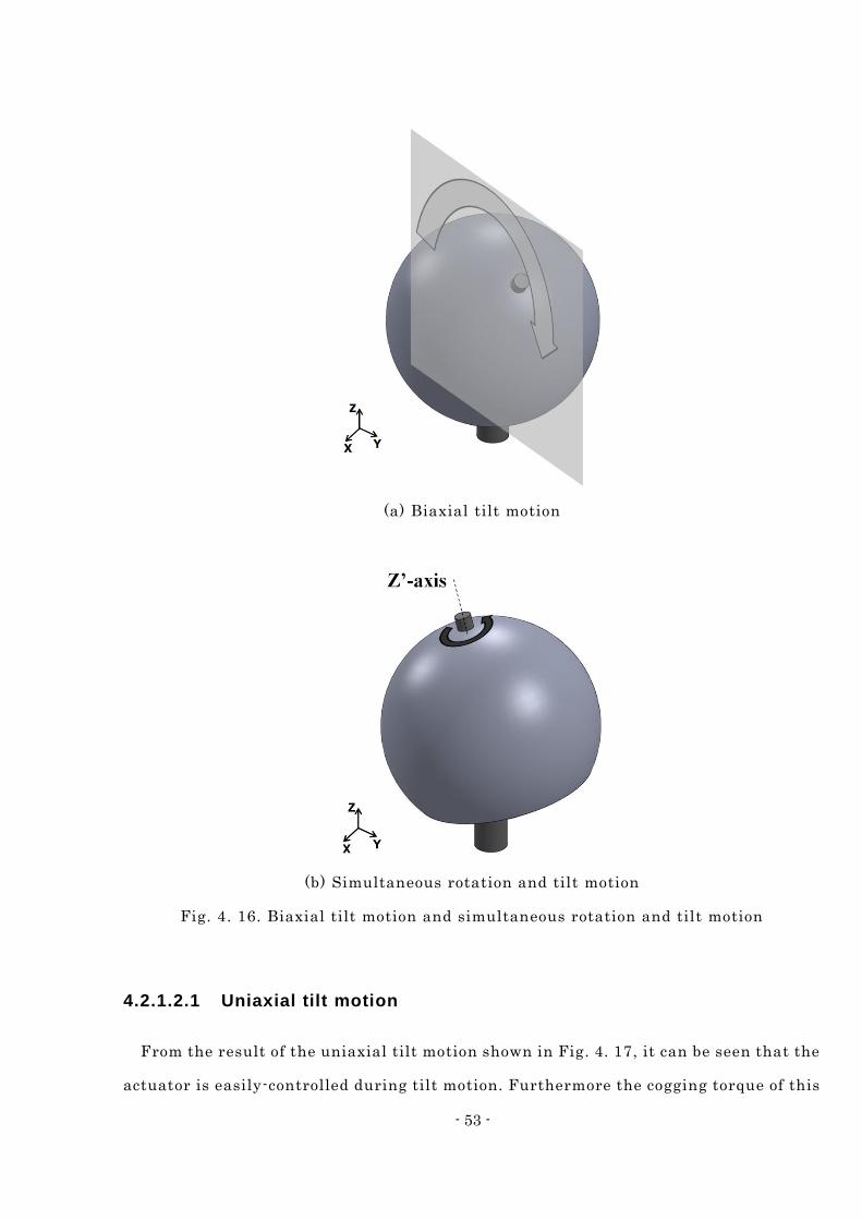
(a) Biaxial tilt motion
(b) Simultaneous rotation and tilt motion
Fig. 4. 16. Biaxial tilt motion and simultaneous rotation and tilt motion
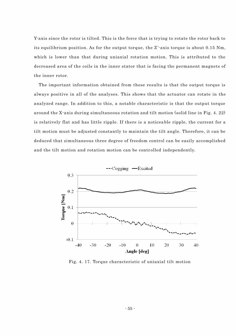
4.2.1.2.1 Uniaxial tilt motion
From the result of the uniaxial tilt motion shown in Fig. 4. 17, it can be seen that the
actuator is easily-controlled during tilt motion. Furthermore the cogging torque of this
- 54 -
actuator is relatively small and the equilibrium point is at the center sinc e the cogging
torque value is 0, and its gradient is negative when the actuator is tilted becaus e the
current density is decreased. The average output torque is 0.2 Nm.
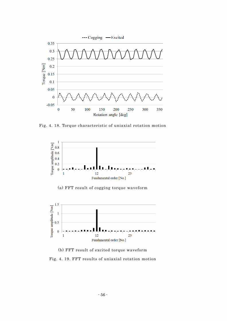
4.2.1.2.2 Uniaxial rotation motion
Fig. 4. 18 shows the torque characteristics of the uniaxial rotation motion. The
fundamental order of the cogging torque is 12, which is the least common multiple of
the pole and slot numbers. The fundamental order of the excited torque is also 12 as
shown in Fig. 4. 19. This means that the cogging torque is dominant in the excited
torque ripple.
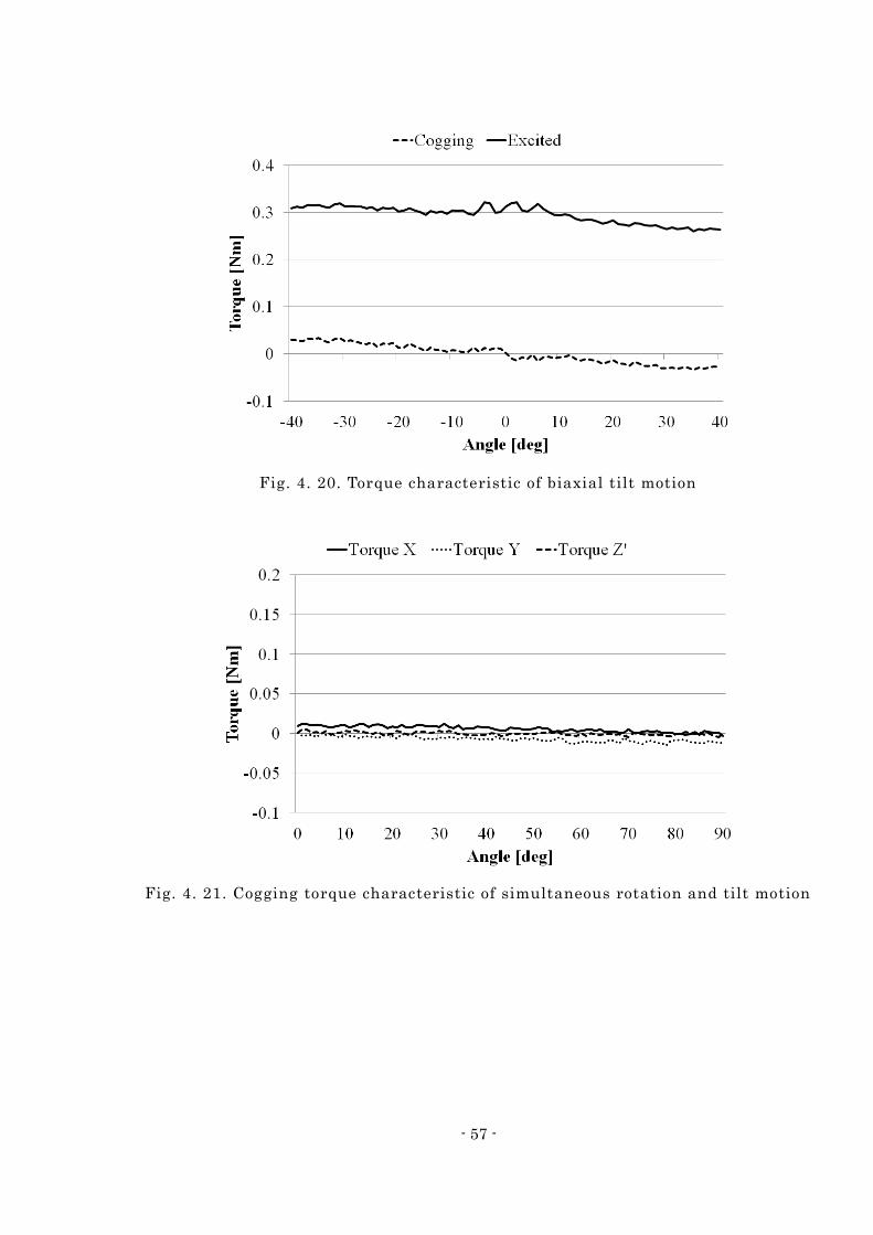
4.2.1.2.3 Biaxial tilt motion
The analyzed results shown in Fig. 4. 20 are the cogging and output torque
characteristics of the biaxial tilt motion. In this analysis, the rotor tilts toward the 45
degrees angle due to the resultant force of the X - and Y-axes motions as shown in Fig. 4.
16 (a). Since all four coils on the stator are excited, the output torque is higher than
that of uniaxial motion. Furthermore the cogging torque characteristics during biaxial
tilt motion are about the same gradient as that during uniaxial tilt motion. Therefore
the cogging torque characteristics will be the same during tilt motion in any arbitrary
direction.
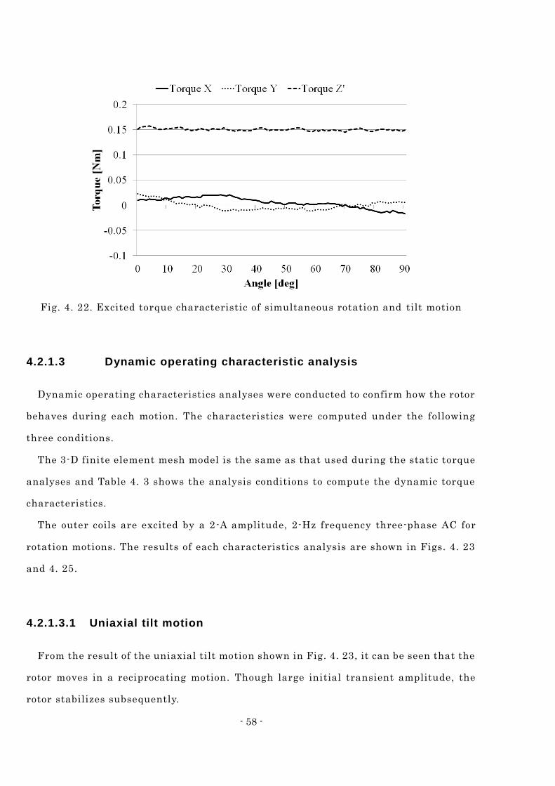
4.2.1.2.4 Simultaneous rotation and tilt motion
Figs. 4. 21 and 4. 22 are the analyzed results of the simultaneous rotation and tilt
motion. Fig. 4. 16 (b) shows that the rotor was rotated around the Z ’-axis which is the Z
axis that has been rotated 20 degrees around the X-axis. From the analyzed result of
the cogging torque, it can be seen that little cogging torque is generated around the
- 55 -
Y-axis since the rotor is tilted. This is the force that is trying to rotate the rotor back to
its equilibrium position. As for the output torque, the Z ’-axis torque is about 0.15 Nm,
which is lower than that during uniaxial rotation motion. This is attributed to the
decreased area of the coils in the inner stator that is facing the permanent magnets of
the inner rotor.
The important information obtained from these results is that the output torque is
always positive in all of the analyses. This shows that the actuator can rotate in the
analyzed range. In addition to this, a notable characteristic is that the output torque
around the X-axis during simultaneous rotation and tilt motion (solid line in Fig. 4. 22)
is relatively flat and has little ripple. If there is a noticea ble ripple, the current for a
tilt motion must be adjusted constantly to maintain the tilt angle. Therefore, it can be
deduced that simultaneous three degree of freedom control can be easily accomplished
and the tilt motion and rotation motion can be controlled independently.
Fig. 4. 17. Torque characteristic of uniaxial tilt motion
- 56 -
Fig. 4. 18. Torque characteristic of uniaxial rotation motion
(a) FFT result of cogging torque waveform
(b) FFT result of excited torque waveform
Fig. 4. 19. FFT results of uniaxial rotation motion
- 57 -
Fig. 4. 20. Torque characteristic of biaxial tilt motion
Fig. 4. 21. Cogging torque characteristic of simultaneous rotation and tilt motion
- 58 -
Fig. 4. 22. Excited torque characteristic of simultaneous rotation and tilt motion
4.2.1.3 Dynamic operating characteristic analysis
Dynamic operating characteristics analyses were conducted to confirm how the rotor
behaves during each motion. The characteristics were computed under the following
three conditions.
The 3-D finite element mesh model is the same as that used during the static torque
analyses and Table 4. 3 shows the analysis conditions to compute the dynamic torque
characteristics.
The outer coils are excited by a 2-A amplitude, 2-Hz frequency three-phase AC for
rotation motions. The results of each characteristics analysis are shown in Figs. 4. 23
and 4. 25.
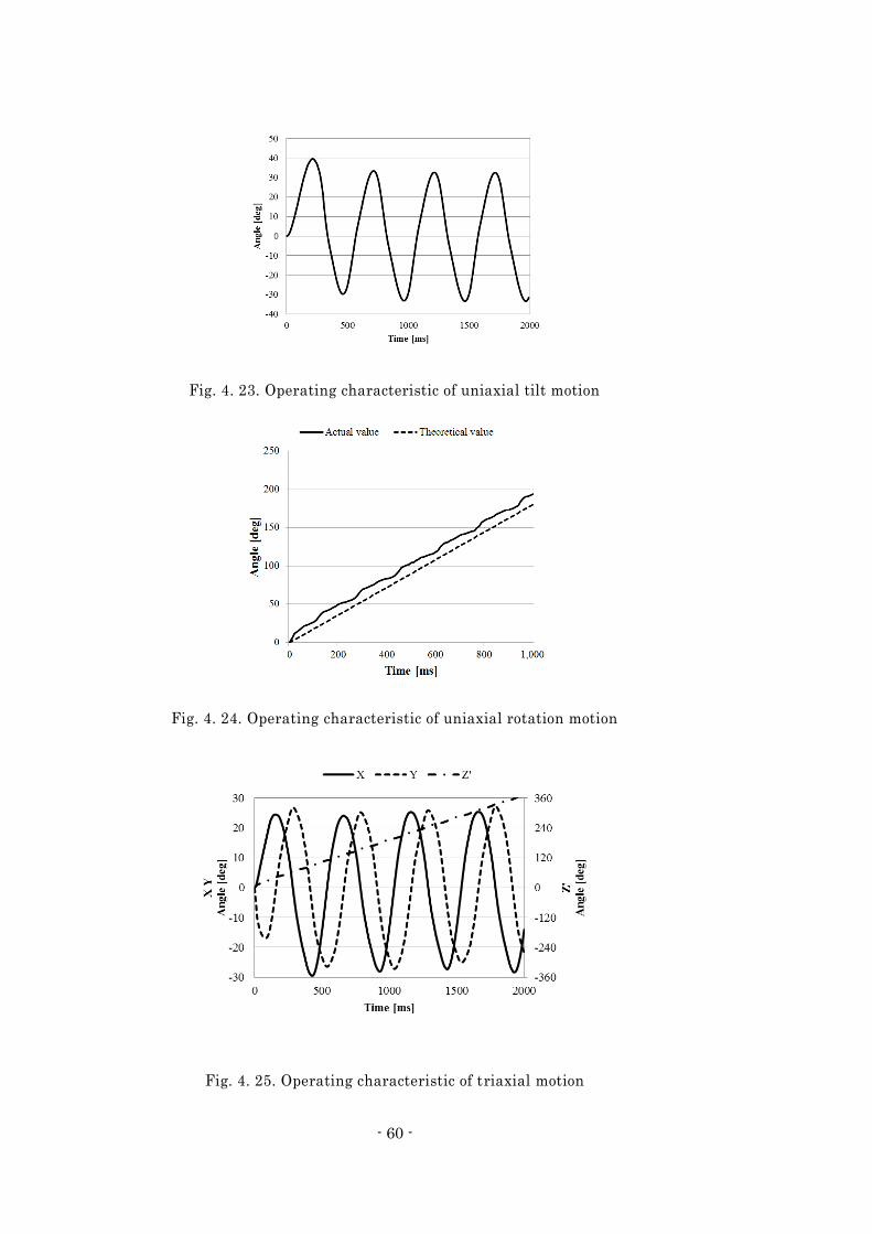
4.2.1.3.1 Uniaxial tilt motion
From the result of the uniaxial tilt motion shown in Fig. 4. 23, it can be seen that the
rotor moves in a reciprocating motion. Though large initial transient amplitude, the
rotor stabilizes subsequently.
- 59 -
4.2.1.3.2 Uniaxial rotation motion
In the rotation motion, the rotor should theoretically rotate 180 degrees per second
because the frequency of the electrical angle is 2 Hz. As shown in Fig. 4. 24, the
analyzed result shows a good agreement with this theoretical value and the rotor
(mover) synchronizes with the rotating magnetic field, though small ripples which
resulted mainly from the cogging torque can be seen.
4.2.1.3.3 Triaxial motion
Fig. 4. 25 shows the analyzed result of a triaxial simultaneous motion combining the
circular motion and the tilted rotation. From the analyzed result, it can be confirmed
that the rotor is rotating around the Z ’-axis and at the same time the Z ’-axis is rotating
along a circular path. This result shows that a simultaneous triaxial motion is possible
by just simply combing the current control for each uniaxial motion.
Table 4. 3. Analysis condition of dynamic characteristics
Number of element 738,768
Number of time steps Uniaxial rotation 80
Other analyses 160
Total CPU time [hour] Uniaxial rotation 14
Other analyses 20
Moment of inertia [kg*m2] Tilt 1.62 × 10 -4
Rotation 1.25 × 10 -4
- 60 -
Fig. 4. 23. Operating characteristic of uniaxial tilt motion
Fig. 4. 24. Operating characteristic of uniaxial rotation motion
Fig. 4. 25. Operating characteristic of triaxial motion
- 61 -
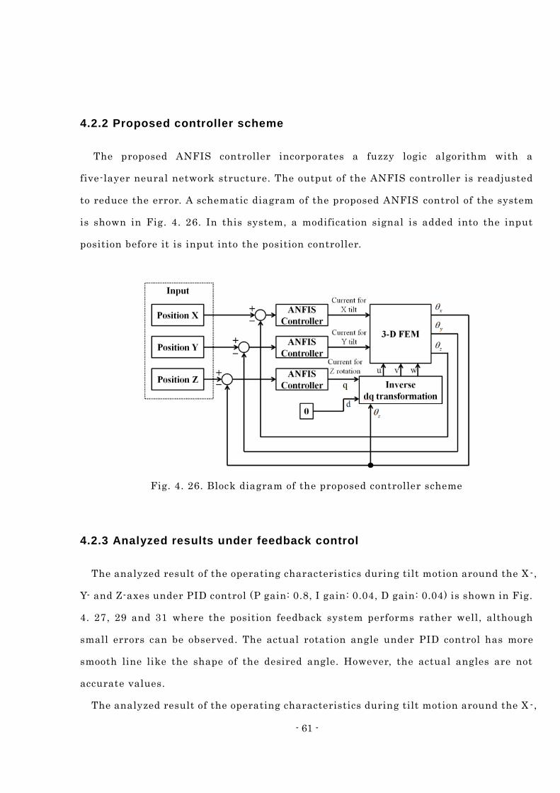
4.2.2 Proposed controller scheme
The proposed ANFIS controller incorporates a fuzzy logic algorithm with a
five-layer neural network structure. The output of the ANFIS controller is readjusted
to reduce the error. A schematic diagram of the proposed ANFIS control of the system
is shown in Fig. 4. 26. In this system, a modification signal is added into the input
position before it is input into the position controller.
Fig. 4. 26. Block diagram of the proposed controller scheme
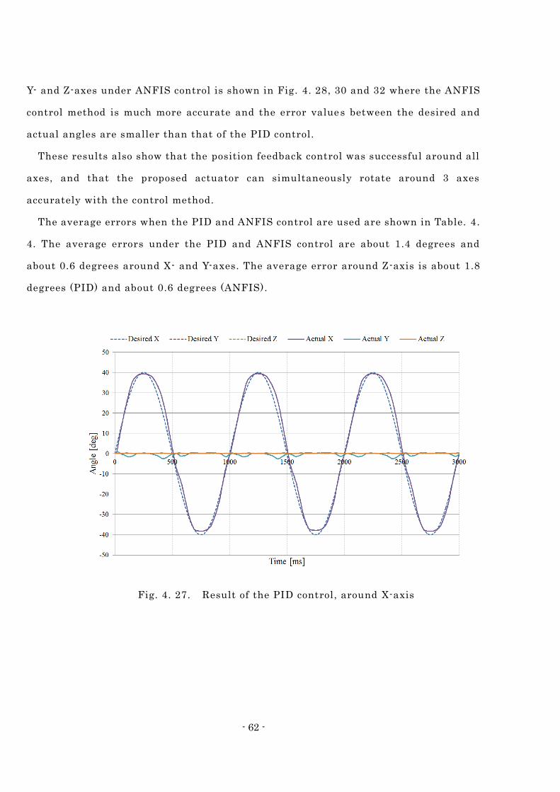
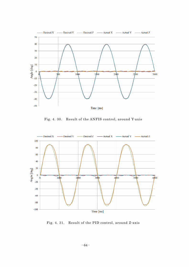
4.2.3 Analyzed results under feedback control
The analyzed result of the operating characteristics during tilt motion around the X -,
Y- and Z-axes under PID control (P gain: 0.8, I gain: 0.04, D gain: 0.04) is shown in Fig.
4. 27, 29 and 31 where the position feedback system performs rather well, although
small errors can be observed. The actual rotation angle under PID control has more
smooth line like the shape of the desired angle. However, the actual angles are not
accurate values.
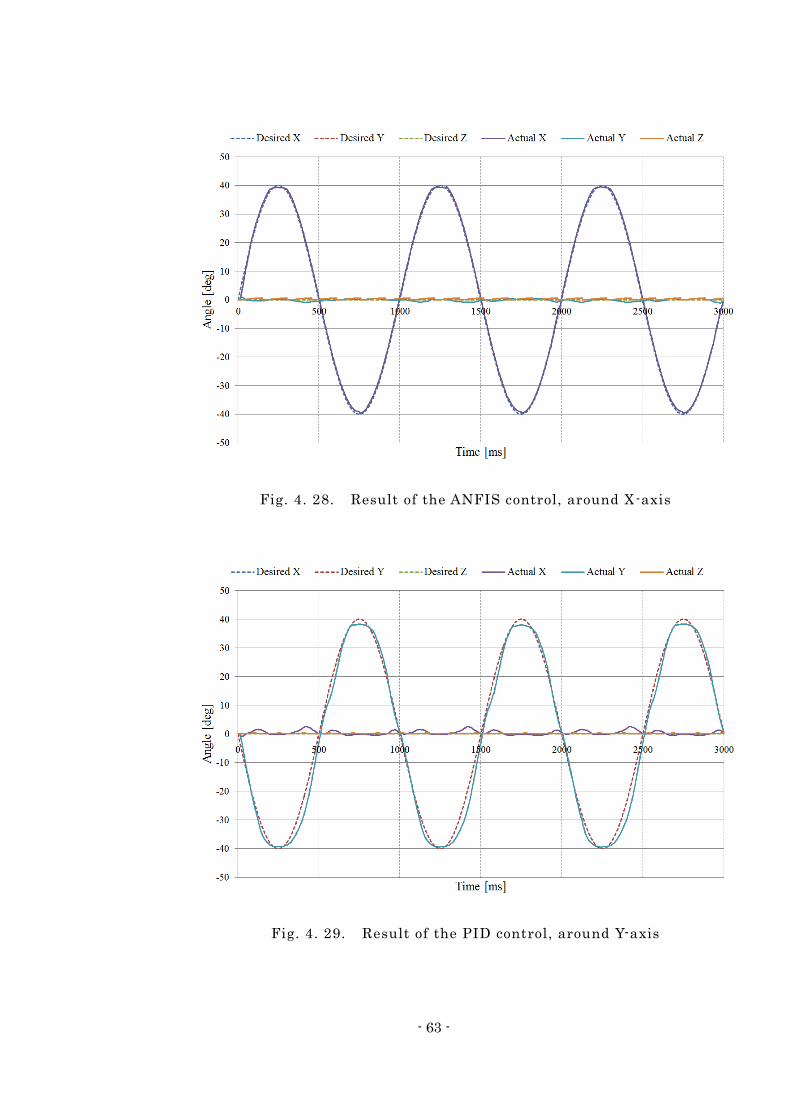
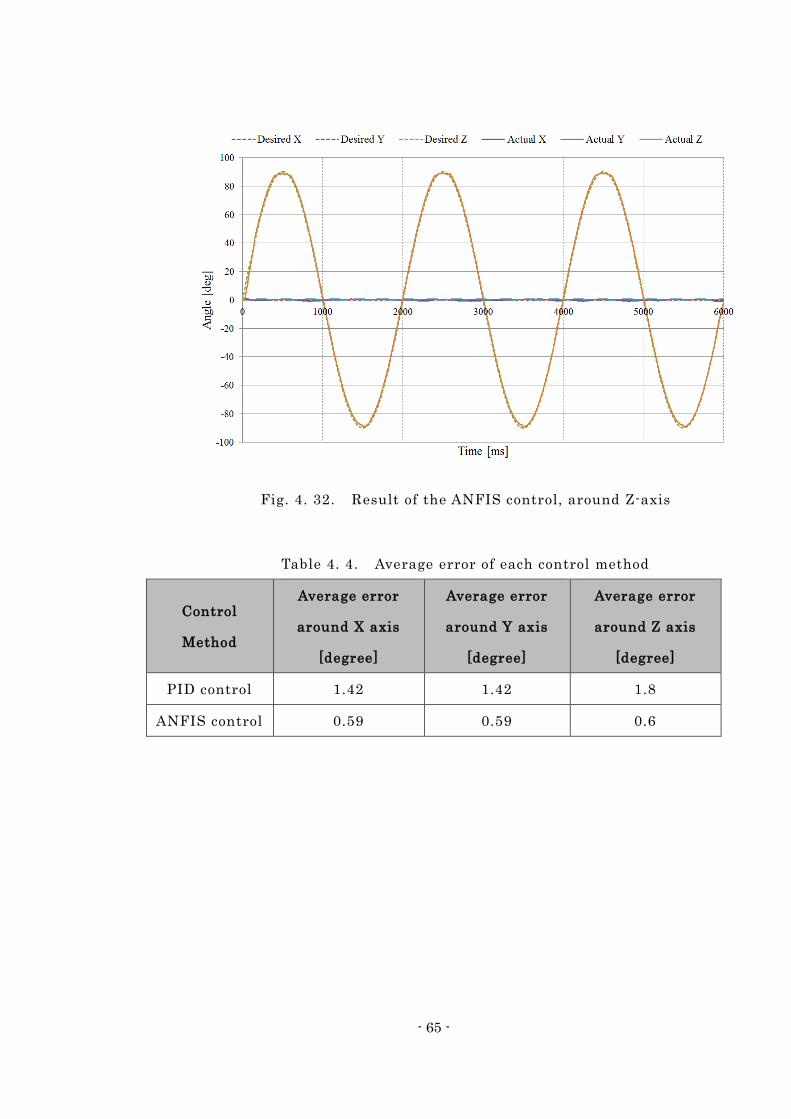
The analyzed result of the operating characteristics during tilt motion around the X -,
- 62 -
Y- and Z-axes under ANFIS control is shown in Fig. 4. 28, 30 and 32 where the ANFIS
control method is much more accurate and the error values between the desired and
actual angles are smaller than that of the PID control.
These results also show that the position feedback control was successful around all
axes, and that the proposed actuator can simultaneously rotate around 3 axes
accurately with the control method.
The average errors when the PID and ANFIS control are used are shown in Table. 4.
4. The average errors under the PID and ANFIS control are about 1.4 degrees and
about 0.6 degrees around X- and Y-axes. The average error around Z-axis is about 1.8
degrees (PID) and about 0.6 degrees (ANFIS).
Fig. 4. 27. Result of the PID control, around X-axis
- 63 -
Fig. 4. 28. Result of the ANFIS control, around X-axis
Fig. 4. 29. Result of the PID control, around Y-axis
- 64 -
Fig. 4. 30. Result of the ANFIS control, around Y-axis
Fig. 4. 31. Result of the PID control, around Z-axis
- 65 -
Fig. 4. 32. Result of the ANFIS control, around Z-axis
Table 4. 4. Average error of each control method
Control
Method
Average error
around X axis
[degree]
Average error
around Y axis
[degree]
Average error
around Z axis
[degree]
PID control 1.42 1.42 1.8
ANFIS control 0.59 0.59 0.6
- 66 -
Summary Chapter 5
This thesis extensively studied multi -degree-of-freedom spherical actuators and
intelligent control.
Chapter 1 started off with the comparison of the conventional multi degree of
freedom mechanism combining a spherical actuator and plurality of motors and
clarified the advantage of the spherical actuator and the significance of a development.
The previous research examples of a spherical actuator are showed. In addition, the
purpose of this research, “Proposal of 3-degree-of-freedom spherical actuator using
voice coil motor principle” and “Feedback control using adaptive neuro-fuzzy inference
system (ANFIS) control method” are shown and the objective of the research is
described.
Chapter 2 moved on to the topic of a new spherical actuator. In order to achieve a
large angle of the tilt motion, high tilt torque, easy control and good dynamic
performance, a design flow chart is considered. A proposed spherical actuator with a
new structure is described. The structure of the proposed actuator and its operating
principle are explained.
Chapter 3 explained the adaptive neuro fuzzy inference system (ANFIS) for
feedback control of a spherical actuator.
In Chapter 4, the verification of a 2-DOF spherical actuator and proposed spherical
actuator using ANFIS feedback control method are described. Firstly, in order to verify
the ANFIS using a prototype of the 2-DOF spherical actuator. By the results of
experiments, it became clear that the drive around each axis can be controlled without
complicated inputs to each coil, which was required for the conventional spherical
actuator. Secondly, the analyzed results of proposed spherical actuator with ANFIS
- 67 -
control. The analyzed results showed the feedback control method using ANFIS more
accuracy than other control method.
The spherical actuator is capable of multi -DOF rotational motion within a single
joint. Previous spherical actuators had problems with modeling, ma nufacturing and
control. In this thesis, a novel spherical actuator with 3 -DOF was proposed. In order to
overcome the complex actuation principle of the existing spherical actuators, the
proposed spherical actuator used the VCM principle.
The ANFIS is used for improving the performance of feedback control. ANFIS has
the advantage of expert knowledge of the fuzzy inference system (FIS) and learning
capabilities of the neural networks (NN) for control of a nonlinear system. The gains
and parameters for feedback control are auto-tuned using a combination of the least
squares estimation and back propagation. Therefore, a control method using ANFIS
will produce more accurate results compared with other control methods.
- 68 -
References
1. J. Wang, K. Mitchell, G.W. Jewell, D. Howe, “Multi-degree-of-freedom spherical
permanent magnet motors”, in: Robotics and Automation, 2001. Proceedings 2001
ICRA. IEEE International Conference on, vol. 2, pp. 1798 -1805, 2001.
2. L. Yan, I.-M. Chen, C.K. Lim, G. Yang, K.-M. Lee, “Design, Modeling and
Experiments of 3-DOF Electromagnetic Spherical Actuators, Springer, 2011 .
3. M. K. Rashid, and Z. A. Khalil : “Configuration Design and Intelligent Stepping of
a Spherical Motor in Robotic Joint”, Journal of Intelligent and Robotic Systems,
Vol.40, pp.165-181, 2004.
4. L. Rossini, O. Ch'etelat, E. Onillon, and Y. Perriard : "Force and Torque Analytical
Models of a Reaction Sphere Actuator Based on Spherical Harmonic Rotation and
Decomposition," IEEE/ASME Transactions, Vol .PP, pp.1-13, 2012.
5. G.S. Chirikjian, D. Stein, “Kinematic design and commutation of a spherical
stepper motor”, Mechatronics, IEEE/ASME Transactions on, 4, pp.342 -353, 1999.
6. K. Davey, G. Vachtsevanos, R. Powers, “The analysis of fields and torques in
spherical induction motors”, Magnetics, IEEE Transactions on, 23, pp. 273-282,
1987.
7. A. Foggia, E. Olivier, F. Chappuis, J.C. Sabonnadiere, “A new three degrees of
freedom electromagnetic actuator”, in: Industry Applications Society Annual
Meeting, 1988., Conference Record of the 1988 IEEE, vol. 1, pp. 137-141, 1988.
8. B. Dehez, G. Galary, D. Grenier, B. Raucent, “Development of a Spherical Induction
Motor With Two Degrees of Freedom”, Magnetics, IEEE Transactions on, vol. 42, pp.
2077-2089, 2006.
9. K. –M. Lee, J. Pei, R. Roth, “Kinematic analysis of a three-degree-of-freedom
- 69 -
spherical wrist actuator”, Mechatronics, pp. 581-605, 1994.
10. Zhi Zhou, Kok-Meng Lee, “Real-time motion control of a multi -degree-of-freedom
variable reluctance”, in: Robotics and Automation, 1996. Proceedings., 1996 IEEE
International Conference on, vol. 3, pp. 1050-4729, 1996.
11. Kok-Meng Lee, Zhiyong Wei, Jeffry Joni, “Parametric study on pole geometry and
thermal effects of a VRSM”, in: Robotics, Automation and Mechatronics, 2004 IEEE
Conference on, vol. 1, pp. 548-553, 2004.
12. Kok-Meng Lee, Hungsun Son, “Torque Model for Design and Control of a Spherical
Wheel Motor”, in: Advanced Intelligent Mechatronics. Proceedings, 2005
IEEE/ASME International Conference on, pp. 335 -340, 2005.
13. Kok-Meng Lee, Hungsun Son, J. Joni, “Concept Development and Design of a
Spherical Wheel Motor (SWM)”, Proceedings of the 2005 IEEE International
Conference on Robotics and Automation, pp. 3652-3657, 2005.
14. Liang Yan, I-Ming Chen, Chee Kian Lim, Guilin Yang, Wei Lin, Kok-Meng Lee,
“Design and Analysis of a Permanent Magnet Spherical Actuator ”, IEEE/ASME
Transactions on Mechatronics, vol. 13, pp. 239-248, 2008.
15. Yusuf Ö ner, “ A permanent magnet spherical rotor design and three dimensional
static magnetic analysis”, Sensors and Actuators A: Physical, vol. 137, pp. 200 -208,
2007.
16. T. Shigeki, Z. Guoqiang, M. Osamu, “Development of new generation spherical
ultrasonic motor”, Proceedings of IEEE International Conference on Robotics and
Automation, vol. 3, pp. 2871-2876, 1996.
17. E. Purwanto, S. Toyama, “Control method of a spherical ultrasonic motor ”,
Proceedings 2003 IEEE/ASME International Conference on Advanced Intelligent
Mechatronics (AIM 2003), vol. 2, pp. 1321-1326, 2003.
18. Chunsheng Zhao, Zhirong Li, Weiqing Huang, “Optimal design of the stator of a
three-DOF ultrasonic motor”, vol. 121, pp. 494-499, 2005.
19. T. Takizawa, M. Shinoda, K. Wakabayashi, K. Takamine, Y. Ikawa, I. Satoh, “High
Speed Access Mechanism For 90mm 1 “Height Optical Disk Drive”, Conference
- 70 -
Digest Joint International Symposium on Optical Memory and Optical Data
Storage 1993, pp. 93-94, 1993.
20. Chang Seop Koh, Osama A. Mohammed, Jun-O Kim, Song-yop Hahn, “Optimum
design of voice coil motor with constant torque coefficients using evolution
strategy”, vol. 75, pp. 6045-6047, 1994.
21. Dong-Ju Lee, Kang-Nyung Lee, No-Cheol Park, Young-Pil Park, Hyuk Kim,
Suk-Won Lee, Hyoung Gil Choi, Moon Gu Lee, Jiho Uh, Jung-Woo Park, Yong-Hwan
Choi, Dong-Jin Lee, “Development of 3-axis nano stage for precision positioning in
lithography”, IEEE International Conference Mechatronics and Automation, 2005,
vol. 3, pp. 1598-1603, 2005.
22. F. C. Williams, E. R. Laithwaite, J. F. Eastham, “Development and design of
spherical induction motors”, Proceedings of the IEE – Part A: Power Engineering,
vol. 106, pp. 471-484, 1959.
23. DM Munnoz, “Spherical Machines: A Literature Review [Elektronisk resurs], IEA,
2005.
24. Shigeki Toyama, A. Kobayashi, “Development of Spherical Ultrasonic Motor”, CIRP
Annals – Manufacturing Technology, vol. 45, pp. 27-30, 1996.
25. Tomoaki Mashimo, Shigeki Toyama, Hiroshi Ishida, “Design and implementation of
spherical ultrasonic motor”, IEEE Transactions on Ultrasonics, Ferroelectrics, and
Frequency Control, vol. 56, pp. 2514-2521, 2009.
26. W. Wang, K. Wang, G. W. Jewell, D. Howe, “Design and control of a novel spherical
permanent magnet actuator with three degrees of freedom ”, IEEE/ASME
Transactions on Mechatronics, vol. 8, pp. 457-468, 2003.
27. B. Ackermann, H. Steinbusch, T. Vollmer, J. Wang, G. W. Jewell, D. Howe, “A
spherical permanent magnet actuator for a high-fidelity force-feedback joystick”,
Mechatronics, vol. 14, pp. 327-339, 2004.
28. Hungsun Son, Kok-Meng Lee, “Distributed Multipole Models for Design and
Control of PM Actuators and Sensors ”, IEEE/ASME Transactions on Mechatronics,
vol. 13, pp. 228-238, 2008.
- 71 -
29. Kok-Meng Lee, Kun Bai, Jungyoul Lim, “Dipole Models for Forward/Inverse Torque
Computation of a Spherical Motor”, IEEE/ASME Transactions on Mechatronics, vol.
14, pp. 46-54, 2009.
30. Hungson Son, Kok-Meng Lee, “Open-Loop Controller Design and Dynamic
Characteristics of a Spherical Wheel Motor ”, IEEE Transactions on Industrial
Electronics, vol. 57, pp. 3475-3482, 2010.
31. Liang Yan, I-Ming Chen, Chee Kian Lim, Guilin Yang, Kok-Meng Lee, “Modeling
and Iron-Effect Analysis on Magnetic Field and Torque Output of Electromagnetic
Spherical Actuators With Iron Stator”, IEEE/ASME Transactions on Mechatronics,
vol. 17, pp. 1080-1087, 2012.
32. J. Wang, G. W. Jewell, D. Howe, “Modelling of a novel spherical permanent magnet
actuator”, Proceedings of International Conference on Robotics and Automation,
vol. 2, pp. 1190-1195, 1997.
33. K. H. Ang, G. Chong, and Y. Li, “PID control system analysis, design, and
technology,” IEEE Trans. Control Syst. Technol., vol. 13, no. 4, pp. 559 -576, 2005.
34. J.-S.R. Jang, “ANFIS: Adaptive-network-based fuzzy inference system,” IEEE
Transactions on Systems, Man, and Cybernetics, vol. 23, pp. 665 -685, 1993.
35. Chun-Tian Cheng, Jian-Yi Lin, Ying-Cuang Sun, Kwokwing Chau, “Long -Term
Prediction of Discharges in Manwan Hydropower Using Adaptive-Network-Based
Fuzzy Inference Systems Models,” ICNC 2005, pp. 1152 -1161, 2005.
36. Simon Haykin, “Neural Networks and Learning Machines,” Prentice Hall, 2008.
37. Warren S. McCulloch and Walter H. Pitts, “A Logical Calculus of The Ideas
Immanent in Nervous Activity,” Bull Math Biophys, vol. 5, pp. 115 -133, 1943.
38. W. Duch, N. Jankowski, “Survey of neural transfer function,” Neural computing
surveys 2, pp. 163-212, 1999.
39. A.K. Jain, M. Jianchang, K.M. Mohiuddin, “Artificial neural networks: a tuto rial,”
Computer 29 (3), pp. 1-44, 1996.
40. H. Takagi, “Fusion technology of neural networks and fuzzy systems: a chronicled
progression from the laboratory to our daily lives, ” International Journal of
- 72 -
Applied Mathematics and Computer Science, Vol. 10, pp. 647-673, 2000.
41. B. Widrow, M. E. Hoff, “Adaptive switching circuits,” IRE WESCON Convention
Record, pp. 96-104, 1960.
42. T. Takagi and M. Sugeno, “Derivation of fuzzy control rules from human operator ’s
control actions,” in Proceedings IFAC Symposium Fuzzy Information, Knowledge
Representation and Decision Analysis, pp. 55-60, 1983.
43. R.J.S. Jang, C.T. Sun, and E. Mitzutani, “Neuro-Fuzzy and Soft Computing,” A
Computational Approach to Learning and Machine Intelligence, Pre ntice-Hall, Inc,
1997.
- 73 -
Research Achievements
Published Papers
(1) J. Chu, N. Niguchi, K. Hirata, "Hybrid Artificial Intelligent Control
for Feedback Control of Outer Rotor Spherical Actuator", Sensing
Technology: Current Status and Future Trends IV, Journal of
SPRINGER, Vol. 12, pp.253-268, 2015.01
(2) Junghyun Chu, Noboru Niguchi, Katsuhiro Hirata, "Analysis of a
3-Degree-of-Freedom Spherical Actuator using VCM principle", The
transactions of the Korean Institute of Power Electronics, 2017.06
International Conferences
(1) Junghyun Chu, Noboru Niguchi, Katsuhiro Hirata, "Feedback
Control of Outer Rotor Spherical Actuator Using Adaptive
Neuro-Fuzzy Inference System", Proceedings of the Seventh
International Conference on Sensing Technology, Wellington, S7.20,
pp. 405-409, 2013.12.
(2) J. Chu, N. Niguchi, K. Hirata, "Design and analysis of a new
spherical actuator," Proceedings of IEEE International Magnetics
Conference (Intermag2015), Beijing, China, BG-11, 2015.05.