Embed Size (px)
Citation preview
Computer Numerically Controlled Machine
Presentation Of Training Underwent At
On
Submitted by:M.Abhishek Krishnan (R800209032)Siddharth Pratap Singh (R800209065)

BHEL HARIDWARIndia’s economical backbone
• BHEL is the largest engineering and manufacturing enterprise in India in the energy/infrastructure sector. •BHEL was established more than 40 years ago, ushering in the indigenous Heavy Electrical Equipment industry in India. •BHEL has been earning profits continuously since 1971-72 and paying dividends since 1976-77.
BHEL PRODUCTION
BHEL produces the following equipments
GeneratorTransformerTurbine MotorValves
BHEL has the following achievements:- • Installed equipment for over 90,000 MW of power generation -- for Utilities, Captive and Industrial users. • Supplied over 2,25,000 MVA transformer capacity and other equipment operating in Transmission & Distribution network up to 400 kV (AC & DC). • Supplied over 25,000 Motors with Drive Control System to Power projects, Petrochemicals, Refineries, Steel, Aluminum, Fertilizer, Cement plants, etc. • Supplied Traction electrics and AC/DC locos to power over 12,000 kms Railway network. • Supplied over one million Valves to Power Plants and other Industries.
• BHEL employs 42,600 highly skilled and committed employees.
CNC SYSTEMS
Introduction
Numerical control (NC) is a method employed for controlling the motions of a machine tool slide and its auxiliary functions with input in the form of numerical data. A computer numerical control (CNC) is a microprocessor-based system to store and process the data for the control of slide motions and auxiliary functions of the machine tools. The CNC system is the heart and brain of a CNC machine which enables the operation of various machine members such as slides, spindles, etc. as per the sequence programmed into it, depending on the machining operations.
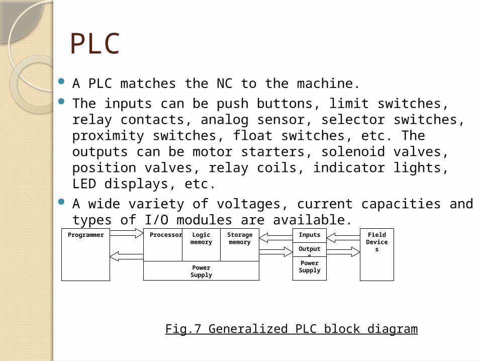
PLC A PLC matches the NC to the machine. The inputs can be push buttons, limit switches, relay
contacts, analog sensor, selector switches, proximity switches, float switches, etc. The outputs can be motor starters, solenoid valves, position valves, relay coils, indicator lights, LED displays, etc.
A wide variety of voltages, current capacities and types of I/O modules are available.
Processor Logic memory
Storage memory
PowerSupply
Inputs
Outputs
Power Supply
Programmer Field Devices
Fig.7 Generalized PLC block diagram
Configuration Of CNC System
A CNC system basically consists of the following:
Central processing unit (CPU)Servo-control unitOperator control panelMachine control panelOther peripheral deviceProgrammable logic controller (PLC)
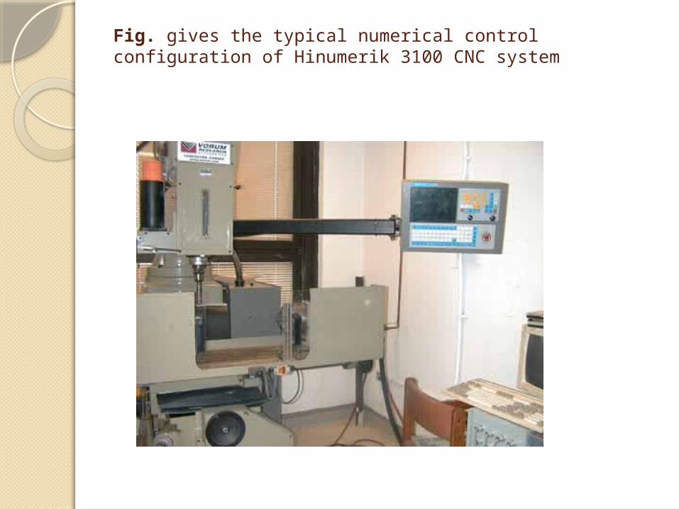
Fig. gives the typical numerical control configuration of Hinumerik 3100 CNC system
Blocks of the CNC Machines
Central Processing Unit (CPU)The CPU is the heart and brain of a CNC system. It accepts the information stored in the memory as part program. This data is decoded and transformed into specific position control and velocity control signals. It also oversees the movement of the control axis or spindle whenever this does not match the programmed values, a corrective action is taken.
Servo Control Unit
This unit acts in unison with the CPU for the movement of the machine axes. The CPU sends the control signals generated for the movement of the axis to the servo control unit and the servo control unit convert these signals into the suitable digital or analog signal to be fed to the machine tool axis movement. This also checks whether machine tool axis movement is at the same speed as directed by the CPU. In case any safety conditions related to the axis are overruled during movement or otherwise they are reported to the CPU for corrective action.
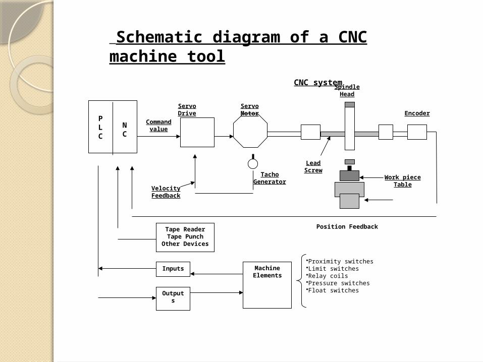
NC
PLC
Servo Drive Servo Motor
Spindle Head
Work pieceTable
Encoder
Position Feedback
TachoGenerator
VelocityFeedback
Tape ReaderTape Punch
Other Devices
MachineElements
Inputs
Outputs
LeadScrew
Command value
•Proximity switches•Limit switches•Relay coils•Pressure switches•Float switches
CNC system
Schematic diagram of a CNC machine tool
Servo-Control Unit
The servo-drive unit converts the command values, which are interfaced with the axis and the spindle motors.
The servo-control unit receives the
position feedback signals for actual movement of the machine tool axes from the feedback devices (like linear scales, rotary encoders, resolves, etc.). The velocity feedback is generally obtained through tacho generators.
SERVO-DRIVES
The servo-drive receives signals from the CNC system and transforms it into actual movement on the machine. The actual rate of movement and direction depend upon the command signal from CNC system. There are various types of servo-drives, viz., dc drives, ac drives and stepper motor drives. A servo-drive consists of two parts, namely, the motor and the electronics for driving the motor.
OPERATOR CONTROL SYSTEM
The operator control panel provides the user interface to facilitate a two-way communication between the user, CNC system and the machine tool. This consists of two parts:
Video Display Unit (VDU)Keyboard
VIDEO DISPLAY UNIT (VDU)The VDU displays the status of the various parameters of the CNC system and the machine tool. It displays all current information such as:Complete information of the block currently being
executedActual position value, set or actual difference,
current feed rate, spindle speedDisplay of all entered data, user programs, user
data, machine data, etc.
POSITION FEEDBACK
A closed-loop system, regardless of the type of feedback device, will constantly try to achieve and maintain a given position by self-correcting. As the slide of the machine tool moves, its movement is fed back to the CNC system for determining the position of the slide to decide how much is yet to be traveled and also to decide whether the movement is as per the commanded rate.
VELOCITY FEEDBACK
Velocity feedback must be present along with the position feedback whenever CNC system are used for contouring, in order to produce correct interpolation and also specified acceleration and deceleration velocities. The tacho generator used for velocity feedback is normally connected to the motor and it rotates whenever the motor rotates, thus giving an analog output proportional to the speed of motor.
OPEN-LOOP SYSTEM
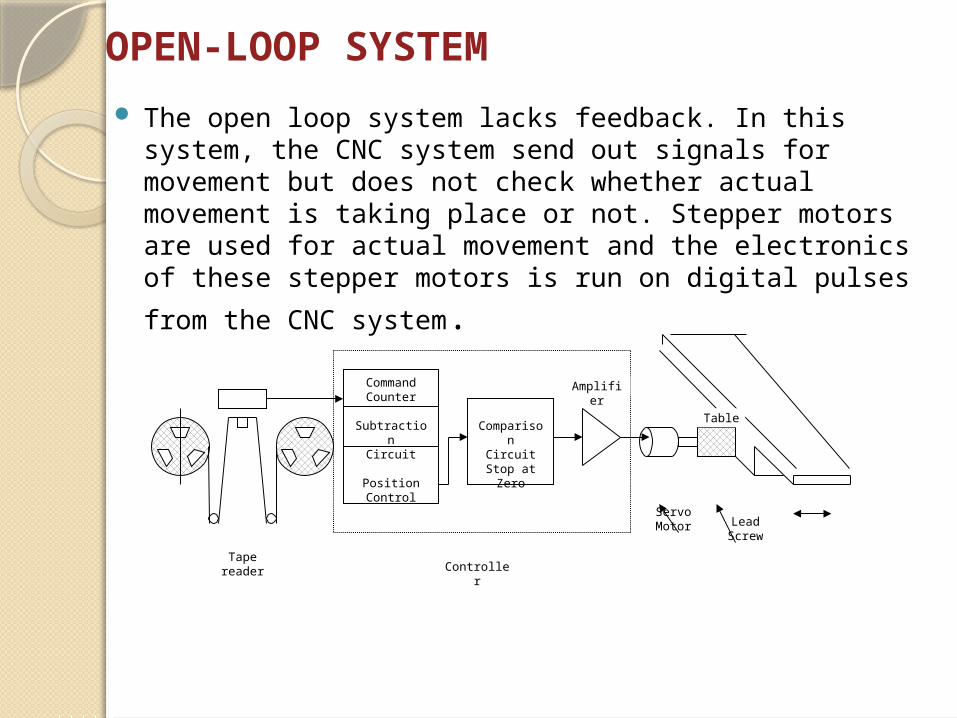
The open loop system lacks feedback. In this system, the CNC system send out signals for movement but does not check whether actual movement is taking place or not. Stepper motors are used for actual movement and the electronics of these stepper motors is run on digital pulses
from the CNC system.
ComparisonCircuitStop at
Zero
CommandCounter
SubtractionCircuit
PositionControl
Tape readerController
Servo Motor Lead
Screw
Table
Amplifier
Closed-loop System
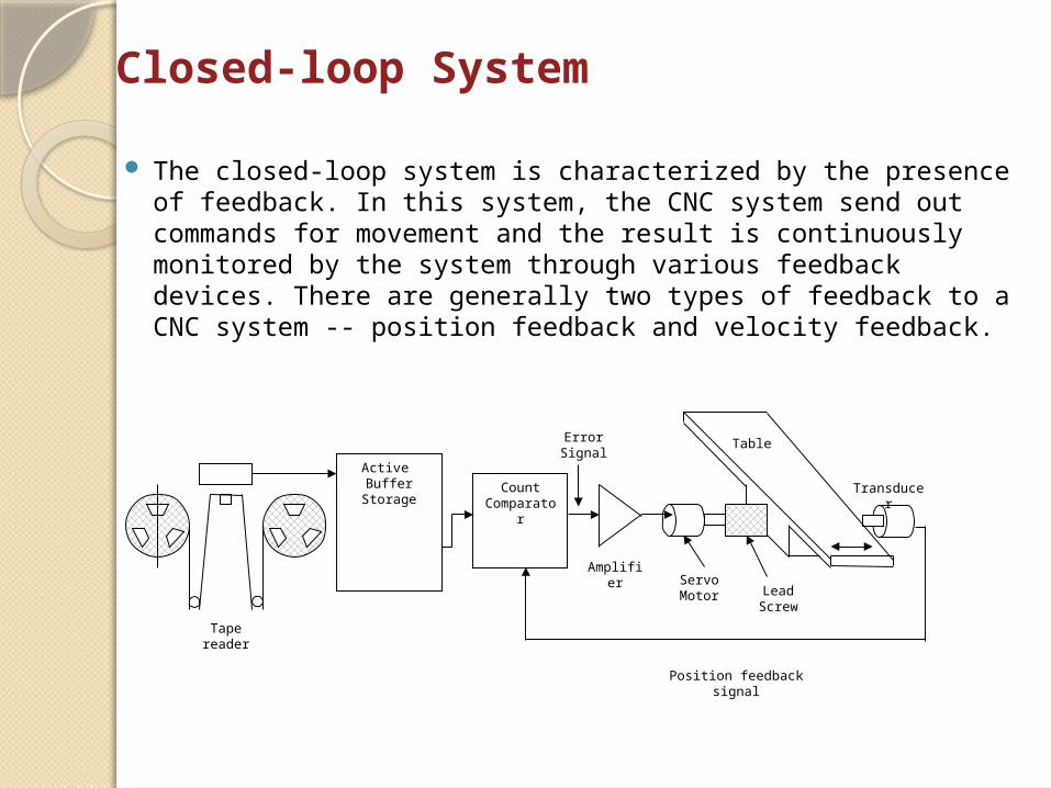
The closed-loop system is characterized by the presence of feedback. In this system, the CNC system send out commands for movement and the result is continuously monitored by the system through various feedback devices. There are generally two types of feedback to a CNC system -- position feedback and velocity feedback.
CountComparator
Active Buffer
Storage
Tape reader
Servo Motor Lead
Screw
Table
Amplifier
Position feedback signal
ErrorSignal
Transducer
MACHINE CONTROL PANEL (MCP)
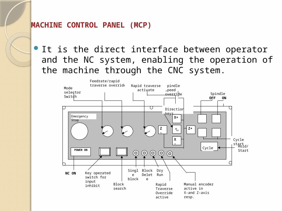
It is the direct interface between operator and the NC system, enabling the operation of the machine through the CNC system.
Z -
X -
Z+
X+
POWER ON
Emergency Stop
Cycle
Mode selector Switch
Spindle speed override
Feedrate/rapid traverse override Rapid traverse activate
Direction keys
SpindleOFF ON
FeedHold/Start
Cycle start
NC ON Key operated switch for input inhibit
Block search
Single block
Dry Run
Block Delete
Rapid TraverseOverride active
Manual encoder active inX-and Z-axis resp.
Modes of Operation
Generally, the CNC system can be operated in the following modes: Manual modeManual data input (MDI) modeAutomatic modeReference modeInput modeOutput mode, etc.
ADVANTAGES OF CNC MACHINE Higher flexibility Increased productivity Consistent quality Reduced scrap rate Reliable operation Reduced non productive time Reduced manpower Shorter cycle time High accuracy Reduced lead time Just in time (JIT) manufacture Automatic material handling Lesser floor space Increased operation safety Machining of advanced material

THANK YOU