Embed Size (px)
Citation preview

I N C O R P O R A T E DSUNRISE TELECOM
22 Great Oaks Blvd. San Jose, CA 95119Tel: 1-408-363-8000 Fax: 1-408-363-8313
Sunrise Telecom..... A Step Ahead
SunSet xDSL
User’s ManualVersion 2.01nSSxDSL-160
MAN-10000-US002 REV C
Copyright 2001Sunrise Telecom Incorporated
This device uses software either developed by Sunrise or licensedby Sunrise from third parties. The software is confidential andproprietary. The software is protected by copyright and containstrade secrets of Sunrise or Sunrise's licensors. The purchaser ofthis device agrees that it has received a license solely to use thesoftware as embedded in the device, and the purchaser is prohib-ited from copying, reverse engineering, decompiling, or disassem-bling the software.

SunSet xDSL Revision CTable of Contents
Chapter 1 Introduction ...............................................................5
Chapter 2 Initial Setup ............................................................9
Chapter 3 Product Description .............................................. 111.0 Keypad Functions ........................................................... 122.0 LEDs............................................................................... 173.0 Connector Panels ............................................................ 213.1 TDR/LINE/DMM Panel ..................................................... 213.2 Module Side Panel .......................................................... 213.3 Top Panel ........................................................................ 233.4 Replacing the Battery Pack ............................................. 243.5 NV Ram Erase ................................................................ 25
Chapter 4 TDR ...................................................................... 271.0 TDR Setup Screen .......................................................... 272.0 TDR Results .................................................................... 302.1 Using the AUTO Search Function .................................... 302.2 Finding Multiple Faults .................................................... 352.3 Sample Trouble Indications on the TDR ........................... 383.0 Performing a TDR Measurement ...................................... 41
Chapter 5 DMM Applications ................................................. 431.0 Measuring Capacitance ................................................... 442.0 Measuring Resistance..................................................... 453.0 Measuring AC Voltage ..................................................... 464.0 Measuring DC Voltage ..................................................... 475.0 DMM Application ............................................................. 48
Chapter 6 Line Measurements .............................................. 491.0 Single-ended line tests .................................................... 511.1 Background Noise ........................................................... 511.1.1 PSD (ADSL DMT/CAP) Background Noise ................. 511.1.2 Other Background Noise Tests ..................................... 591.2 Level Meter ..................................................................... 601.3 Frequency Generator ....................................................... 611.4 Coil Detection .................................................................. 621.5 Impulse Noise ................................................................. 642.0 Controller tests ................................................................ 682.1 Insertion Loss ................................................................. 682.1.1 Insertion Loss for DMT/CAP Freq. Band ...................... 682.1.2 Single Frequency Insertion Loss Tests .......................... 722.2 Signal-to-Noise Test ........................................................ 732.3 Loop Resistance Test ....................................................... 753.0 Responder testing ........................................................... 774.0 Remote Auto Test ............................................................ 79

Chapter 7 Printing & Storing Results ..................................... 851.0 Storing Results ............................................................... 851.1 Viewing Stored Results ................................................... 871.2 Locking Stored Results ................................................... 871.3 Clearing Stored Results .................................................. 871.4 Storing/ Recalling Results ............................................... 882.0 Printing Results .............................................................. 892.1 Configuring the Serial Port ............................................... 892.2 Printing from the SunSet xDSL ....................................... 912.3 Printing to a TAN printer ................................................... 932.4 Printing to a PC................................................................ 94
Chapter 8 Auto Test .............................................................. 951.0 Auto Test Single .............................................................. 951.1 Test Procedure ................................................................ 952.0 Measurement Settings .................................................. 108
Chapter 9 Customer Information ......................................... 1111.0 Customer Service ......................................................... 1112.0 Express Limited Warranty ............................................. 113
Index..................................................................................... 115

Ch.1 Introduction 5
Chapter 1 Introduction
You will soon find your SunSet xDSL an indispensable tool fortroubleshooting and qualifying DSL circuits. Figure 1, DSL Span,shows the SunSet xDSL testing from the Central Office, the Cross-Box (or B-Box), and the NID (Network Interface Device).
ATU-RNID
TR
RT
CrossBox
MDF
DSLAM
Network
POTSSplitterPOTS
at C.O.
Figure 1 DSL Span
Physical Layer Testing
Time Domain Reflectometer (TDR)
• Locate cable faults• Determine distance to: open, short, load coil, and bridge tap
Load Coil Detector
• Determine presence of load coils
Capacitance Meter
• Estimate loop length• Determine capacitive line balance

6 SunSet xDSL Rev. C
Resistance Meter
• Verify isolation resistance• Estimate loop length (with the far end shorted)• Detect the presence of shorts
DC Volt Meter
• Verify proper POTS line power• Verify proper line powering for HTU-R (if necessary)
AC Volt Meter
• Detect presence of AC induced voltage T/G, R/G, T/R, fromadjacent power lines
Frequency Response/Attenuation Measurement
• Determine the loss characteristics for the entire DMT/CAP/DSL band.
PSD Background Noise Measurement
• Characterize spectral compatibility in binder• Measure ambient noise
Loop Resistance
• Estimate loop length
SunSet xDSL Plug-in ModulesThe SunSet xDSL provides incredible versatility for a hand-
held test set. Plug-in modules allow you to assemble the test setyou need for testing digital subscriber lines or other technologies.The modular platform extends the life of your test equipment in-vestment. You simply need to add a new module whenever therequirement for a new technology arises.
Currently, the following modules are available:
ADI ADSL ATU-R (SSxDSL-10)This module performs ADI ATU-R emulation for both installing
and troubleshooting ADSL circuits. This module performs the sametests as the SSxDSL-3, but to ADI chipset standards.
Alcatel ADSL ATU-R (SSxDSL-3)This module performs Alcatel ATU-R emulation for both in-
stalling and troubleshooting ADSL circuits. A one-button accep-tance test turns up the link with the DSLAM (ATU-C) and displaysvital information such as: current rate, maximum attainable rate,and noise margin, all within seconds.

Ch.1 Introduction 7
Additional information helps you troubleshoot marginal ortroublesome circuits. A bits per tone graphic displays the precisebit assignment per tone. By checking the frequencies of low bitlevels, you can detect possible interferers. Alarm status & linkmeasurements show any alarm or error conditions that have oc-curred at the near or far end. Both current and history informationprovides you with the full picture. Optional software adds a sec-ond step by pinging the far end gateway to verify completion ofvirtual circuit provisioning.
Alcatel ADSL ATU-C (SSxDSL-4)This module performs Alcatel ATU-C emulation for both in-
stalling and troubleshooting ADSL circuits. ATU-C emulation is akey application for qualifying ADSL circuits before the DSLAM isinstalled and working in the central office. A one-button accep-tance test turns up the link with the far end modem (ATU-R) andquickly displays vital information such as: current rate, maximumattainable rate, and noise margin.
Comprehensive setup configurations gives the user a widerange of troubleshooting tools. You may set the exact rate, noisemargin, etc. for rate adaptive or fixed rate circuits. A carrier maskfeature enables you to manually control the 256 tones to experi-ment and determine optimum settings for the DSLAM.
Pairgain T1 HDSL (SSxDSL-1)This module performs Pairgain HDSL T1 emulation for install-
ing and troubleshooting HDSL circuits. The module combines bothHTU-C and HTU-R functions. Upon turn-up, the set provides a fullreport of span status including max/min/avg rate and noise mar-gin for both HDSL loops. Further results provide error and alarmcounters for both near and far end. Optional software providesbasic testing at the T1 interface.
VF TIMS (SSxDSL-6)This module provides baseband 20 Hz to 20 kHz TIMS testing
from both 2-wire and 4-wire interfaces. Tone generation includesfixed tone, 3-tone slope, and configurable frequency sweep tests.Measurements include signal-to-noise, impulse noise, and noisewith filters (3k-flat, 15k-flat, C-message). The module also con-tains signaling and dialing functions for placing calls.

8 SunSet xDSL Rev. C
IDSL (SSxDSL-5)This module supports both IDSL and ISDN BRI testing. The
IDSL capabilities support BERT Testing on both the U and the S/T Interface in a point-to-point mode. In addition, EOC commandssupport B1, B2, and 2B+D Loopbacks from the Central Officeside (LT Interface) of the circuit. They allow for U-BRiTE cards,Repeaters, and NT1 looping. ISDN Basic Rate testing includescall setup and X.25 call setup.
Datacom/DDS (SSxDSL-9)This module provides transmission and BERT testing from both
Datacom and DDS-4W interfaces. Datacom testing supports DTE,DCE, and monitor modes from a V.35, RS232, RS449, RS530, orX.21 interface. The module performs DDS- 4wire testing at the CPE(DSU/CSU emulation) for both primary and secondary channels.
SDSL (SSxDSL-7)The SDSL module is designed for line qualification, installa-
tion, and troubleshooting of SDSL circuits. Based on the ConexantRS8973 SDSL chipset, it can be configured as a general SDSLtester to prequalify a copper pair for any rate from 144 kbps to2320 kbps. It also can emulate a specific SDSL modem, HTU-Cat the central office or HTU-R at the customer premise, for serviceverification and troubleshooting applications. Currently, modememulation supports systems compatible with the Conexant RS8973chip set, including Lucent TNT and Stinger, Nokia Speedlink, andCopper Mountain Copper Edge.
Dual T1 (SSxDSL-8)The Dual T1 module offers full T1 functionality. One Dual T1
module in combination with the SunSet xDSL provides combined,integrated testing offering TDR, DMM, TIMS, T1, DSL, BRI, andDatacom.
Alcatel ADSL-over-ISDN (SSxDSL-11)The Alcatel ADSL-over-ISDN module is designed for Euro
ADSL-over-ISDN systems.

9Ch.2 Initial Set-Up
Chapter 2 Initial Setup
Use the following procedure for unpacking and testing yournew SunSet xDSL:
1. Remove the packing list from the shipping container.2. Remove the SunSet xDSL and accessories from the shipping
container.3. Inspect all parts and immediately report any damage to the
carrier and to Sunrise Telecom.4. Verify that all parts specified on the packing list were received.5. Complete the Warranty Registration Card and return it immedi-
ately to Sunrise Telecom.
Note : Sunrise Telecom must receive your Warranty RegistrationCard in order to provide you with updated software releases.
6. Ensure that the software cartridge is fully seated in it’s slot.When properly installed, the top of the cartridge is pushed flushwith the top of the ejector button. The SunSet xDSL has twosoftware card slots:
• The inside card contains the actual software and optionsneeded to operate the SunSet xDSL. This card may be upgradedin the field to provide you with new software options or softwarereleases.
• The outside slot may be used in the future for extra memorystorage.
7. Plug the AC Battery Charger into an AC wall outlet and connectit to the SunSet xDSL. The charger plugs in at the top of theSunSet xDSL, where it is labelled 15VDC.
• The SunSet xDSL uses a NiMH battery. Use only the adaptersupplied with the test set (SS138-D). The SS138-D AC adaptershould be used for charging the test set batteries only.
• For optimum performance, the test set should be used onbatteries only.
8. Power the SunSet xDSL (with the red POWER key at the bottom)and verify that it passes the SELF TEST. If the test set doesnot turn on immediately, it may need to charge for up to 5minutes before it can run.

10 SunSet xDSL Rev. C
• Upon first powering up, the screen should show several Down-load and Calibrate messages. All should display “PASS” on theright side. If a module is installed, the final message should read“Downloading (type of module) Module PASS.”
• The SunSet xDSL main screen now appears.
9. Setting the System Clock:A. To set the System Clock to the current time, press the
MENU key.B. Cursor down to OTHER SETUP and press ENTER.C. Press the down arrow key to cursor down to the SYSTEM
CLOCK. Press ENTER.D. At DATE: Use the INC (F1) and DEC (F2) to set the Month,
date, and Year. Use the right and left arrow keys to move thecursor. When you’re finished setting the date, press thedown arrow key to access the TIME setting.
E. At TIME: Use the INC (F1) and DEC (F2) keys to set theHour, Minutes, and Seconds.
F. When you have finished entering the date and time, pressSET (F3) to save your entries.
10.Charge the unit overnight before its first use on battery.
Note : For optimum performance of the test set, use with batteriesonly.
11.Put the test set and accessories into the soft carrying case (ifit was ordered).
11Ch.3 Product Description
Chapter 3 Product Description
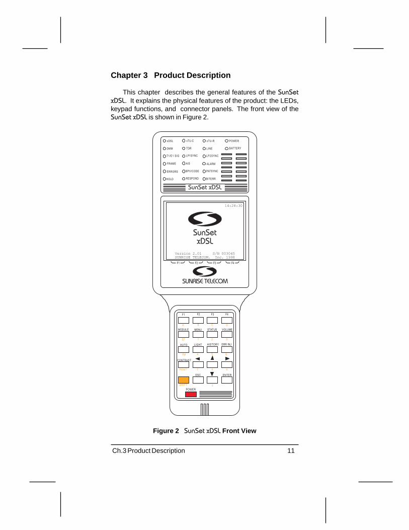
This chapter describes the general features of the SunSetxDSL. It explains the physical features of the product: the LEDs,keypad functions, and connector panels. The front view of theSunSet xDSL is shown in Figure 2.
Figure 2 SunSet xDSL Front View
BATTERY
ALARM
xTU-R POWER
LINE
LP2SYNC
BITERR
xTU-C
TDR
LP1SYNC
BPV/CODE
RESPOND
AISFRAME
xDSL
DMM
T1/E1 SIG
ERRORS
HOLD
PATSYNC
SunSet xDSL
F1 F2 F3 F4
SunSetxDSL
14:28:30
Version 2.01 S/N 003045SUNRISE TELECOM. Inc. 1998
SUNRISE TELECOM
ESC
ERR INJLIGHT
SHIFT
STATUS
F3F1 F2 F4
VOLUME
PRINT 7
CONTRAST
AUTO
ENTER
POWER
HISTORY
8
MENUMODULEA B C D
1 2 3
4 5 6
9
0
E*
F#

12 SunSet xDSL Rev. C
1.0 Keypad Functions
The SunSet xDSL keypad is shown in Figure 3.
PEEL TAB
SHIFT
POWER
F2 F3 F4
ERR INJ
ESC ENTER
MODULE
AUTO
7
F1
LIGHT
MENU STATUS VOLUME
HISTORY
8
A B C D
1 2 3
4 5 6
CONTRAST
9
0
E*
F#
Figure 3 SunSet xDSL Keypad
SunSet xDSL keys can have two distinct meanings:
• The White Label above the key indicates what function will beperformed if the key is pressed by itself (i.e. MODULE orHISTORY).
• The Orange Label below the key shows what function will beperformed if the SHIFT function is activated (i.e. numbers orPRINT).
Shift Key FunctionsTo activate the Shift function, press the orange SHIFT key.
The SHIFT-lock key should not be pressed simultaneously withanother key. Instead, the SHIFT-lock key should be pressed andreleased. At this point, a SHIFT indicator will appear in the upperleft-hand corner of the screen. Then the other key should be pressed.The set will then perform the function indicated on the orange la-bel. SHIFT-lock will remain activated until the SHIFT key is pressedagain and the SHIFT indicator disappears.

13Ch.3 Product Description
Note ::::: The SHIFT indicator should be checked if the keys are notbehaving as expected. If the SHIFT indicator at the upper left-hand corner of the screen indicates the wrong status, simply pressthe SHIFT-lock key.
White Label KeysF1-F4: The F-keys are used to select choices F1 through F4 at thebottom of the LCD display. If more than four F-key options areavailable, a “more” indicator will appear in the F4 position. Press-ing the F4 key will display the other available F-keys.
MODULE: The MODULE key brings up the main menu of the mod-ule installed in the left side. Use this key to access all modulefunctions.
MENU: The MENU key brings up the Main Menu. Use this key toaccess all non-module functions. Figure 4 outlines the Main Menu.

14 SunSet xDSL Rev. C
Figure 4 Main Menu Flowchart
M
EN
U
KE
Y
DM
M
LIN
E
TD
R
Mai
n M
enu
OT
HE
R S
ET
UP
AU
TO
TE
ST
SIN
GLE
AU
TO
TE
ST
ST
OR
AG
E
DIG
ITA
L M
ULT
IME
TE
R
DC
V, A
CV
, OH
M o
r C
AP
LIN
E M
AIN
ME
NU
BA
CK
GR
OU
ND
NO
ISE
LEV
EL
ME
TE
R
FR
EQ
UE
NC
Y G
EN
ER
AT
OR
CO
IL D
ET
EC
TIO
N
IMP
ULS
E N
OIS
E
CO
NT
RO
LLE
R
RE
SP
ON
DE
R
CA
LIB
RA
TIO
N
RE
MO
TE
AU
TO
TE
ST
TIM
E D
OM
AIN
R
EF
LEC
TO
ME
TE
R
OT
HE
R S
YS
TE
M S
ET
UP
NV
RA
M E
RA
SE
MA
NU
FA
CT
UR
E P
RO
FIL
E
SY
ST
EM
CO
NF
IG
SY
ST
EM
CLO
CK
SE
RIA
L P
OR
T C
NF
G
VE
RS
ION
/ O
PT
ION
ME
AS
UR
EM
EN
T S
ET
TIN
GS
AU
TO
TE
ST
SIN
GLE
S
TO
RE
D R
ES
ULT
S
15Ch.3 Product Description
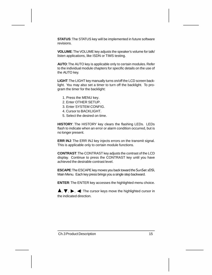
STATUS: The STATUS key will be implemented in future softwarerevisions.
VOLUME: The VOLUME key adjusts the speaker’s volume for talk/listen applications, like ISDN or TIMS testing.
AUTO: The AUTO key is applicable only to certain modules. Referto the individual module chapters for specific details on the use ofthe AUTO key.
LIGHT: The LIGHT key manually turns on/off the LCD screen back-light. You may also set a timer to turn off the backlight. To pro-gram the timer for the backlight:
1. Press the MENU key.2. Enter OTHER SETUP.3. Enter SYSTEM CONFIG.4. Cursor to BACKLIGHT.5. Select the desired on time.
HISTORY: The HISTORY key clears the flashing LEDs. LEDsflash to indicate when an error or alarm condition occurred, but isno longer present.
ERR INJ: The ERR INJ key injects errors on the transmit signal.This is applicable only to certain module functions.
CONTRAST: The CONTRAST key adjusts the contrast of the LCDdisplay. Continue to press the CONTRAST key until you haveachieved the desirable contrast level.
ESCAPE: The ESCAPE key moves you back toward the SunSet xDSLMain Menu. Each key press brings you a single step backward.
ENTER: The ENTER key accesses the highlighted menu choice.
, , , : The cursor keys move the highlighted cursor inthe indicated direction.
16 SunSet xDSL Rev. C
Orange Label KeysThe SHIFT key activates the orange label function written below
some of the keys. The orange SHIFT key activates the SHIFT-lock, meaning that the keys perform the orange label function writ-ten below the key. You will need to press the SHIFT key again todeactivate the SHIFT-lock and return the keys to their normal,white label functions.
The orange shift keys have the following functions:
0-9: The 0-9 keys are used to enter numbers during testing. Ex-amples are entering IP addresses during PING testing or enteringuser test patterns.
A-F: The A-F keys are used to enter hexadecimal values.
PRINT: The PRINT key prints the current screen display to theserial port. This key is functional only if you have selected aGraphic print mode. Refer to Chapter 7, Storing & Printing Re-sults, for more details.

17Ch.3 Product Description
2.0 LEDs
The LEDs (Light Emitting Diodes) provide valuable informa-tion on:
• The SunSet xDSLs current test mode. In TDR testing, the TDRLED lights green.
• The status of the received signal. When the SunSet xDSLdetects an alarm, the ALARM LED lights red.
• The status of modem synchronization. In DSL testing, a solidgreen LED for XTU-R (for ATU-R testing) indicates the SunSetxDSL has achieved synchronization with the DSLAM.
Figure 5 shows the SunSet xDSL LED panel.
SunSet xDSL
BATTERY
FRAME ALARM
xDSL xTU-C xTU-R POWER
DMM TDR LINE
T1/E1 SIG LP1SYNC LP2SYNC
ERRORS PATSYNCBPV/CODE
HOLD RESPOND BIT ERR
AIS
Figure 5 SunSet xDSL LED Panel
The LEDs have the following meanings:
xDSL
• Green: The xDSL LED lights green to indicate that the SunSetis in the xDSL mode. When a modem is installed, the SunSetxDSL starts off in xDSL mode upon powering up.
xTU-CThe xTU-C LED is active when the SunSet xDSL is emulating
an xTU-C (i.e. ATU-C or HTU-C).
• Green: The xTU-C LED lights green when the set has synchedwith the xTU-R.
• Red: The SunSet xDSL has not connected with the xTU-R.• Blinking Red: The SunSet xDSL is attempting to open the link
with the xTU-R.

18 SunSet xDSL Rev. C
xTU-RThe xTU-R LED is active when the SunSet xDSL is emulating
an xTU-R (i.e. ATU-R or HTU-R).
• Green: The xTU-R LED lights green when the set has synchedwith the xTU-C at the Central Office.
• Red: The SunSet xDSL has not connected with the xTU-C.• Blinking Red: The SunSet xDSL is attempting to open the link
with the xTU-C.
DMM
• Green: The DMM LED lights green to indicate that the SunSetxDSL is in the DMM mode.
• Red: The DMM LED lights red only during self test.
TDR
• Green: The xDSL TDR lights green to indicate that the SunSetxDSL is in the TDR mode.
• Red: The TDR LED lights red only during self test.
LINE
• Green: The LINE LED lights green to indicate that the SunSetxDSL is in the LINE mode.
• Red: The LINE LED lights red only during self test.
T1/E1 SIGThe T1/E1 SIG LED is active during test modes with T1 and
E1 signals. For example, HDSL T1/E1 tests the T1/E1 signal.
• Green: The T1/E1 SIG LED lights green when the SunSet xDSLis receiving a T1 or E1 signal.
• Red: The SunSet xDSL is not receiving a T1/E1 signal asexpected.
LP 1 SYNCThe LP 1 SYNC LED is active during test modes with 2 loops.
For example, in HDSL T1/E1 testing this LED displays the statusof HDSL loop 1.
• Green: The LP 1 SYNC LED lights green when loop 1 (i.e. HDSLLoop 1) is in sync.
• Red: The LP 1 SYNC LED lights red when loop 1 is not in sync.

19Ch.3 Product Description
LP 2 SYNCThe LP 2 SYNC LED is active during test modes with 2 loops.
For example, in HDSL T1/E1 testing this LED displays the statusof HDSL loop 2.
• Green: The LP 2 SYNC LED lights green when loop 2 (i.e. HDSLLoop 2) is in sync.
• Red: This LED lights red when loop 2 is not in sync.
FRAMEThe FRAME LED is active when the SunSet xDSL is in a framed
test mode (i.e T1/E1 framing for HDSL testing).
• Green: A green FRAME LED indicates that the SunSet xDSL hasachieved frame sync and the framing found on the receivedsignal matches the framing set in Test Configuration.
• Red: A red LED indicates that the configured framing type is notfound on the received signal. This could indicate either a loss offraming on the received signal or a framing mismatch.
ALARMThe Alarm LED has functions specific to the module in use.
Please refer to plug-in module manual.
ERRORS
• Red: The SunSet xDSL is currently detecting an error.• Blinking Red: The SunSet xDSL previously detected an error, but
that error is no longer present. Pressing the HISTORY key willclear this flashing LED.
BPV/CODE
• Red: The SunSet xDSL is currently detecting a Bipolar Violation(BPV) or Code error.
• Blinking Red: The SunSet xDSL previously detected a BPV orcode error, but that error condition is no longer present. Pressingthe HISTORY key will clear this flashing LED.
HOLD
• Green: You have pressed the HOLD key while in the TDRscreen. This freezes the screen display . This LED is activeonly in TDR mode.
• Red: The HOLD LED lights red only during self test.
20 SunSet xDSL Rev. C
RESPOND
• Green: indicates that the test set is in responder mode. This isapplicable only to LINE testing.
• Red: The RESPOND LED lights red only during self test.
PAT SYNCThe PAT SYNC LED is active whenever the SunSet xDSL is
performing a BERT test with a known test pattern. For example, itis active in HDSL, IDSL, Datacom/DDS, or T1 testing.
• Green: The PAT SYNC LED lights green when the set hasachieved pattern synchronization.
• Red: The SunSet xDSL has lost pattern synchronization orcannot achieve pattern sync.
BIT ERRThe BIT ERR LED is active whenever the SunSet xDSL is
performing a BERT test with a known test pattern. For example, itis active in HDSL, IDSL, Datacom/DDS, or T1 testing.
• Red: The SunSet xDSL is currently detecting bit errors.• Blinking Red: The SunSet xDSL previously detected bit errors,
but they are no longer present. Pressing the HISTORY key willclear this flashing LED.
POWER
• Green: The test set is powered on.
BATTERY
• Green: The SS138D AC Adapter/Charger is connected and thatthe SunSet xDSL is charging.
• Red: This indicates a low battery. You should connect the unitto the SS138D charger as soon as possible.

21Ch.3 Product Description
3.0 Connector Panels
The SunSet xDSL has two side panels and one top panel. Theleft side contains a slot to insert plug-in modules. The right sidecontains an RJ-45 connector jack for physical layer testing: LINE,DMM, and TDR. Make sure to use the correct connector for yourtest. The top panel of the SunSet xDSL has a serial port and DCpower adapter jack.
3.1 TDR/LINE/DMM Panel
The SunSet xDSLs right side contains the RJ-45 connectorjack for all TDR, LINE,and DMM applications. Refer to Figure 6.
TDR/LINE/DMM
Figure 6 Right Side Panel
3.2 Module Side Panel
Warning!Inserting or removing a module with the power on maydamage the module. Always verify that the test set is off
before changing or inserting modules.
The left side of the SunSet xDSL contains a slot to insert aplug-in module. Such modules include: Alcatel ATU-R (SSxDSL-3), Alcatel ATU-C (SSxDSL-4), T1 HDSL (SSxDSL-1), VF TIMS(SSxDSL-6), SDSL (SSxDSL-7), Datacom (SSxDSL-9), ADI ATU-R (SSxDSL-10), and IDSL (SSxDSL-5). Upon ordering the SunSetxDSL with module, the module will already be inserted upon deliv-ery. To remove or change modules, use the following procedure:
1. Make sure the SunSet xDSL is powered off before removing themodule.
2. Loosen the two thumbscrews on either side of the module.3. Gently pull the module out from the slot. Place it in its hard case
or protective wrapper.

22 SunSet xDSL Rev. C
4. While the SunSet xDSL is powered off, insert the other module.Make sure it is firmly seated in the slot.
Note : Inserting or removing the module with the power on maydamage the module.
5. Screw in the two thumbscrews. Make sure these are secure.6. Power up the unit. The screen should show the set is
downloading the new module and this should read PASS.7. Access NV RAM ERASE by pressing the MENU key and
access OTHER SETUP > NV RAM ERASE. You are now readyto begin testing with the new module.
Note : Performing a NV RAM ERASE operation will erase alluser-stored information that has been entered into the test set.All stored results will be erased.

23Ch.3 Product Description
3.3 Top Panel
The top panel is shown in Figure 7, SunSet xDSL Top Panel.
SERIALPORT 15 VDC
Figure 7 SunSet xDSL Top Panel
15 VDC
Warning!Do not use a charger other than the SunSet xDSL charger
(SS138D) provided with your test set.Use of other chargers may cause damage to the SunSet xDSL
and will void your warranty.
CautionDo not use the SS138D charger during normal operation.
For optimum results, we recommend fully charging the testset then performing your tests on battery power alone.
Plug the AC Adapter/Charger into this 15 VDC port. SunriseTelecom provides the SS138D Adapter/Charger; its output is 15VDC, input 100-240 VAC. The unit may be operated while charg-ing, but optimum performance will be with battery operation.
Serial PortThe RJ-11 Serial Port should be used for printing results. Sun-
rise Telecom provides three different cables for connecting to aprinter: RJ-11 to DB-9 (SS144), RJ-11 to DB-25 (SS144A), andRJ-11 to RJ11 (SS144B). Refer to Chapter 7, Storing & PrintingResults , for details on the printer cables and connections.
24 SunSet xDSL Rev. C
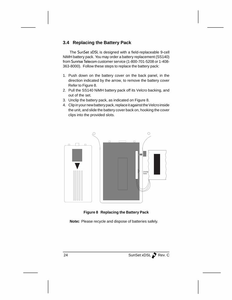
3.4 Replacing the Battery Pack
The SunSet xDSL is designed with a field-replaceable 9-cellNiMH battery pack. You may order a battery replacement (SS140)from Sunrise Telecom customer service (1-800-701-5208 or 1-408-363-8000). Follow these steps to replace the battery pack:
1. Push down on the battery cover on the back panel, in thedirection indicated by the arrow, to remove the battery coverRefer to Figure 8.
2. Pull the SS140 NiMH battery pack off its Velcro backing, andout of the set.
3. Unclip the battery pack, as indicated on Figure 8.4. Clip in your new battery pack, replace it against the Velcro inside
the unit, and slide the battery cover back on, hooking the coverclips into the provided slots.
Uncliphere
Figure 8 Replacing the Battery Pack
Note ::::: Please recycle and dispose of batteries safely.
25Ch.3 Product Description
3.5 NV Ram Erase
WARNING!Performing a NV RAM ERASE operation will erase all user-stored information that has been entered into the test set.
All stored results will be erased.
Erase NV (Non Volatile) RAM erases all the user-storable in-formation entered into the test set. This operation should alwaysbe performed after inserting a new software cartridge. This opera-tion should also be performed as a last resort if the set is notperforming properly. If this is the case, you should initiate EraseNV RAM, only after attempting to correct the problem by:
1. Making sure that the SunSet xDSL is properly configured for theapplication being attempted.
2. Turning the power switch off and on has not corrected theproblem.
Use the following procedure to perform the NV RAM ERASEprocedure:
1. Press the MENU key.2. Access OTHER SETUP.3. Access NV RAM ERASE.4. Press the ENTER key after the warning message is displayed.
A “WORKING” message will be displayed.5. After the set powers up, reconfigure the SunSet xDSL for the
operations you need to perform.

26 SunSet xDSL Rev. C
Ch.4 TDR Menus & Applications 27
Chapter 4 TDR
A Time Domain Reflectometer (TDR) operates by sending apulse of energy down the cable. It then measures any reflectionsthat return to the SunSet xDSL. These reflections are caused byfaults that cause impedance changes in the cable. For example,a load coil looks like a large increase in impedance (the high fre-quency pulses cannot pass through) and can easily be detectedby a TDR. Any major change in the twisted pair’s plastic insulationor the cable fill’s material (like water in the cable) causes a reflec-tion.
A TDR plays an integral role in testing DSL circuits. It can:
• locate bridge taps, indicating the presence of a bridge tap, theexact location, and the length of the lateral.
• locate load coils, showing the presence and exact location ofload coils.
• detect any other circuit faults like an open or shorted cable.
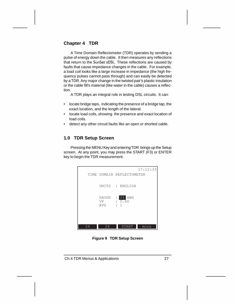
1.0 TDR Setup Screen
Pressing the MENU Key and entering TDR brings up the Setupscreen. At any point, you may press the START (F3) or ENTERkey to begin the TDR measurement.
UNITS : ENGLISH
GAUGE : 24 AWGVP : 0.60AVG : 1
17:12:33TIME DOMAIN REFLECTOMETER
24 moreSTART26
Figure 9 TDR Setup Screen

28 SunSet xDSL Rev. C
UNITSOptions: English or Metric.
This is for display only; you do not change the setting here. Tochange it:
1. Press the MENU key.2. Access OTHER SETUP.3. Access SYSTEM CONFIG.4. Move thew cursor to UNIT; you may now select either English
(F1) or Metric (F2).
GAUGEOptions: Eng: F1= 24/19/28, F2= 26/22, F3= START, & F4= moreMetric: F1= .4/.6/.3, F2= .5/.9, F3= START, & F4= more
• This setting specifies the wire gauge. An incorrect setting willresult in a reduction of measurement range. If you are testinga cable span with mixed gauge values, select the highest gaugevalue.
• The UNITS setting above determines if gauge will be expressedin AWG (English) or mm (Metric).
• In North America, thickness is expressed in AWG (AmericanWire Gauge). A value of 24AWG refers to wire that is 1/24” indiameter.
• Outside North America, wire gauge is expressed by the diam-eter in millimeters.
• 0.4mm roughly compares to 26AWG; 0.5mm roughly to 24AWG.
VPOptions: from .40 to .99
• Use the (F1) and (F2) keys to change the Velocity of Propaga-tion. The more (F4) key sets the increment/decrement factor at+/- .01 or +/-.01
• This setting is important for accurate results; if you are unfamil-iar with Vp settings, please read the following.

Ch.4 TDR Menus & Applications 29
Velocity of PropagationPropagation Velocity (Vp) indicates the speed that the signal
travels down the cable. It is a ratio of the speed in cable to thespeed of light; a value of .65 means the signal travels down thatcable at 65% the speed of light.
Setting the Propagation Velocity is crucial for using a TDR.This calibrates the SunSet xDSL for the particular cable type. Youshould be able to find the Vp in the Cable’s specification sheet orfrom the manufacturer. If you cannot find it, take a representativecable of a known length and measure it with the SunSet xDSLsTDR. Change the Propagation Velocity setting until the SunSetxDSL provides an accurate distance reading.
AVGOptions: 1-5
This setting determines the number of times the SunSet xDSLsends the pulse. If this value is set for greater than one, theSunSet xDSL displays an average of all attempts. Sunrise Telecomrecommends setting the AVG at 1.
Press the START (F3) key to begin the TDR Measurement.

30 SunSet xDSL Rev. C
2.0 TDR Results
After pressing START, the TDR result appears. Look for anyspikes, dips, or sudden changes in the pulse. These indicate pos-sible faults. There are several different methods for finding faults:
1. Press the SEARCH key for auto search; the SunSet xDSL scansthe cable for the first fault.
2. Press the ZOOM_OUT F-key to view the whole cable span.3. Press the PG_RGT or PG_LFT key to scroll through the various
length segments.
Once you have located a fault, you can find its location usingthe cursor (solid line). Press the right/left arrow keys to move thecursor to the fault. The DISTANCE reading at top provides thelocation of the cursor.
2.1 Using the AUTO Search Function
The Auto Search feature searches for the first fault on thecable pair. The SunSet xDSL looks for any dips or spikes in thegraph and displays that segment of the cable to you. Auto searchis a quick and easy way to begin your TDR testing.
13:14:21TDRSHIFT
ZOOM_IN ZOOM_OT SEARCH more
[10 ]MARKER: 960.2 MARKER GAIN
[1616 ][0: 0 ][H: 32 ][V: 1 ]
DISTANCE:970.2 FEET:FOUND
Figure 10 Auto Search

Ch.4 TDR Menus & Applications 31
To use Auto Search:1. Press the SEARCH (F3) key on the screen.2. While the SunSet xDSL is searching for a fault, it will display
“SEARCHING” in the middle of the screen.3. When it has found a fault, it will be displayed on the screen.
“FOUND” appears at the top right, as shown in Figure 10.4. The SunSet xDSL automatically places the cursor near the fault.
The DISTANCE reading at the top left provides the cursor’slocation. Use the left and right arrow keys to adjust the position.
5. If the SunSet xDSL does not find any faults, it will show NONEin the top right. You still may want to zoom out and manuallysearch for any faults.
Adjusting the ZoomYou can use the ZOOM_IN and ZOOM_OT F-keys to scan
the entire cable span for faults of focus on a particular fault orcable segment. ZOOM_OUT shows more of the cable span, whileZOOM_IN focuses on shorter portions. Note the “H” (horizontal)value at bottom right displays the Zoom factor. It can range from1-512 (1 being the closest range and 512 being the farthest out).Zooming out to the maximum value (H= 256 or 512) enables youto view the entire span length so you may better locate cablefaults. Zooming in allows you to interpret potential faults.
Upon entering the TDR screen, press the ZOOM_OT (F2) keyuntil you have zoomed out all the way (H=256 or 512) to see theentire cable span.
13:14:21TDRSHIFT
ZOOM_IN ZOOM_OT SEARCH more
[10 ]MARKER: 384.2 MARKER GAIN
[13763 ][0: 0 ][H: 256 ][V: 4.000]
DISTANCE: 701.5 FEET
STORED
Figure 11 Result Zoomed Out

32 SunSet xDSL Rev. C
Figure 11 shows a bridge tap with the zoom out (H=256). Thisscreen shows the whole cable span: from 10 to 13,763 feet. Youcan start to make out a bridge tap in the far left of the screen. Usethe right arrow key to move the cursor near the fault; the Distancereading shows it at 701 feet.
Press the ZOOM_IN (F1) key to zoom in on the fault. Sincethe SunSet xDSL zooms in on the cursor’s location, move the cur-sor to the fault- then press ZOOM_IN. This screen shows theSunSet xDSL at H=128; the bridge tap is now more visible. Thescreen shows from 10 to 6,886 feet.
13:14:21TDRSHIFT
ZOOM_IN ZOOM_OT SEARCH more
[10 ]MARKER: 268.9 MARKER GAIN
[6886 ][0: 0 ][H: 128 ][V: 1.000]
DISTANCE: 816.7 FEET
STORED
Figure 12 Zooming in Once
Ch.4 TDR Menus & Applications 33
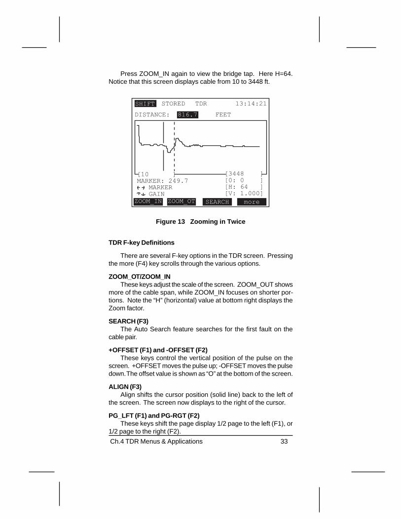
Press ZOOM_IN again to view the bridge tap. Here H=64.Notice that this screen displays cable from 10 to 3448 ft.
13:14:21TDRSHIFT
ZOOM_IN ZOOM_OT SEARCH more
[10 ]MARKER: 249.7 MARKER GAIN
[3448 ][0: 0 ][H: 64 ][V: 1.000]
DISTANCE: 816.7 FEET
STORED
Figure 13 Zooming in Twice
TDR F-key Definitions
There are several F-key options in the TDR screen. Pressingthe more (F4) key scrolls through the various options.
ZOOM_OT/ZOOM_INThese keys adjust the scale of the screen. ZOOM_OUT shows
more of the cable span, while ZOOM_IN focuses on shorter por-tions. Note the “H” (horizontal) value at bottom right displays theZoom factor.
SEARCH (F3)The Auto Search feature searches for the first fault on the
cable pair.
+OFFSET (F1) and -OFFSET (F2)These keys control the vertical position of the pulse on the
screen. +OFFSET moves the pulse up; -OFFSET moves the pulsedown. The offset value is shown as “O” at the bottom of the screen.
ALIGN (F3)Align shifts the cursor position (solid line) back to the left of
the screen. The screen now displays to the right of the cursor.
PG_LFT (F1) and PG-RGT (F2)These keys shift the page display 1/2 page to the left (F1), or
1/2 page to the right (F2).

34 SunSet xDSL Rev. C
CURSOR/MARKER (F1)This key determines the left & right arrow key control. Press
Cursor to move the cursor, solid line, with the left and right arrowkeys. Press Marker to move the marker, dotted line.
Arrow Keys
• The left and right arrow keys are used to move the position ofthe cursor or marker.
• The up and down arrow keys are used to adjust the gain (pulsestrength). Increasing the gain (up arrow) increases the strengthof the reflection.
Lower Display Features
Below the reflection, there are several display items.
MARKER ALIGN more
MARKER: 289.7CURSOR GAIN
[1500 ] [8715 ][O: -2 ][H: 128 ][V: 1.0000
Figure 14 Auto Search Lower Screen Items
[1500 ] shows the distance at the left-most start of the screen.
[8715] shows the distance at the right-most end of the screen.
MARKER: shows the distance between the Marker and the Cur-sor. When the cursor is at the beginning of a bridge tap and themarker is at the open end, this value shows the length of yourbridge tap.
O: shows the Offset value. Offset represents the vertical positionof the pulse on the screen. This can range from +64 (high onscreen) to -64 (low on screen).
H: shows the Zoom factor. Zoom refers to the scale of the screen.This can range from 1-512. 1 shows only a limited portion of thescreen in more detail. 512 shows the whole cable span.
V: shows the Gain value. Gain adjusts the strength of the pulse.This can range from 32 (strongest) to .125 (weakest).

Ch.4 TDR Menus & Applications 35
2.2 Finding Multiple Faults
You can see past a bridge tap, cable splice, wet cable, orother impairments with a TDR. However, a TDR cannot show be-yond an open, load coil, or short. For example, if a load coil isdetected, it must be removed before you can continue looking formore faults with the TDR. Refer to the following scenario for locat-ing multiple faults with your TDR.
ZOOM_IN ZOOM_OT SEARCH more
[10 ]MARKER: 412.8 MARKER GAIN
[3223 ][0: 0 ][H: 64 ][V: 4.000]
FEETDISTANCE: 1589
13:14:21TDRSHIFT
Figure 15 Bridge Tap at 1589 ft
A bridge tap is found at 1589 feet. Note how the Cursor (solidline) indicates its location (DISTANCE). The Marker (dotted line)indicates the length of the lateral (MARKER).
36 SunSet xDSL Rev. C
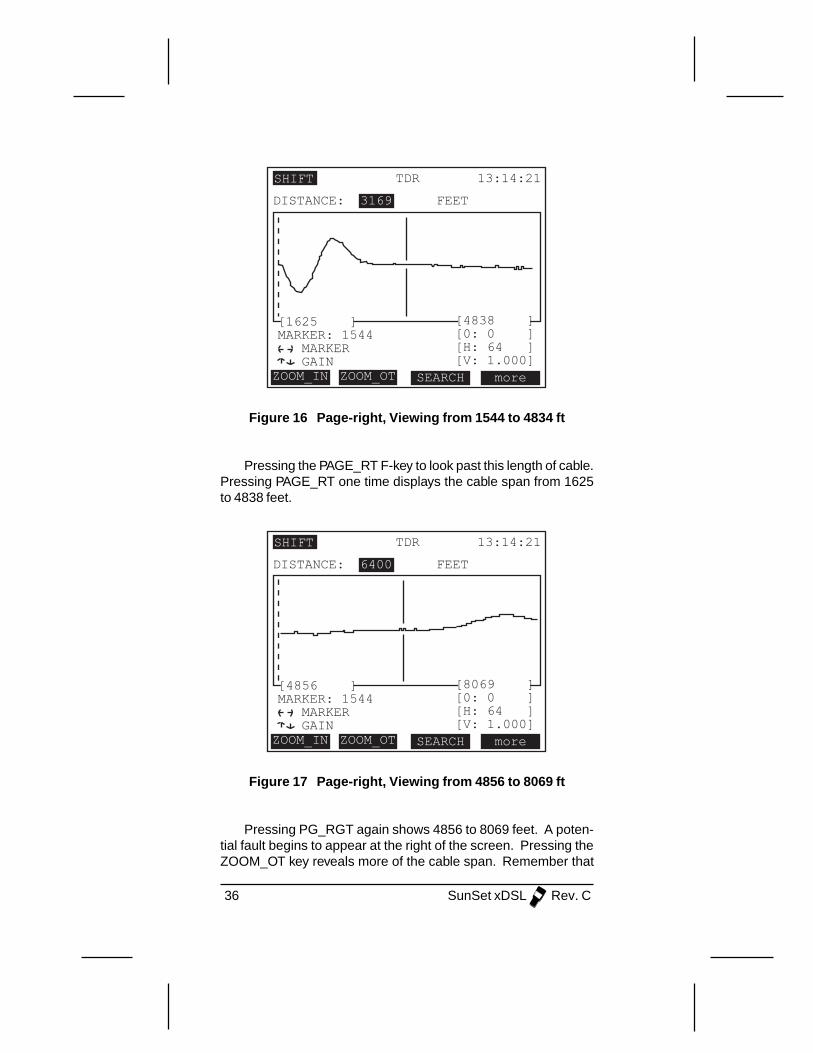
ZOOM_IN ZOOM_OT SEARCH more
[1625 ]MARKER: 1544 MARKER GAIN
[4838 ][0: 0 ][H: 64 ][V: 1.000]
FEETDISTANCE: 3169
13:14:21TDRSHIFT
Figure 16 Page-right, Viewing from 1544 to 4834 ft
Pressing the PAGE_RT F-key to look past this length of cable.Pressing PAGE_RT one time displays the cable span from 1625to 4838 feet.
ZOOM_IN ZOOM_OT SEARCH more
[4856 ]MARKER: 1544 MARKER GAIN
[8069 ][0: 0 ][H: 64 ][V: 1.000]
FEETDISTANCE: 6400
13:14:21TDRSHIFT
Figure 17 Page-right, Viewing from 4856 to 8069 ft
Pressing PG_RGT again shows 4856 to 8069 feet. A poten-tial fault begins to appear at the right of the screen. Pressing theZOOM_OT key reveals more of the cable span. Remember that

Ch.4 TDR Menus & Applications 37
the SunSet xDSL zooms in on the position of the cursor; to focuson a potential fault, move the cursor to that position.
ZOOM_IN ZOOM_OT SEARCH more
[4856 ]MARKER: 2046 MARKER GAIN
[11281 ][0: 0 ][H: 128 ][V: 2.000]
FEETDISTANCE: 6902
13:14:21TDRSHIFT
Figure 18 Zoom out, Viewing from 4856 to 11281 ft
Pressing the ZOOM-OT displays from 4856 to 11281 feet. Theopen is now very visible. The position of the cursor shows it to beat 6902 feet.
Note : You may want to press the up arrow key once to increasethe GAIN. This will make the fault more visible. Note that in thisfigure the GAIN value is 2.00, where it had been 1.00 previously.
TDR Hints:1. Adjust the zoom value to your approximate cable length; check
the right-side distance in brackets. Zooming out as much aspossible (H=256, 512) allows you to view the entire cable length,but it may make locating smaller or near faults more difficult tointerpret.
2. The SunSet xDSL has a fixed pulse width for the span that isdisplayed. At times, when viewing far distant cable, you maywant to increase the gain. This will make far away faults morevisible. Press the up arrow key once to increase GAIN. Notethe GAIN value at the lower right (V).
3. To find the exact distance between two points (i.e the start of abridge tap and the end of that lateral), place the cursor at oneend, and the marker at the other. The MARKER reading belowthe graph provides the difference between the two.
38 SunSet xDSL Rev. C
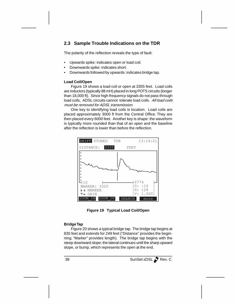
2.3 Sample Trouble Indications on the TDR
The polarity of the reflection reveals the type of fault:
• Upwards spike: indicates open or load coil.• Downwards spike: indicates short.• Downwards followed by upwards: indicates bridge tap.
Load Coil/OpenFigure 19 shows a load coil or open at 3355 feet. Load coils
are inductors (typically 88 mH) placed in long POTS circuits (longerthan 18,000 ft). Since high frequency signals do not pass throughload coils, ADSL circuits cannot tolerate load coils. All load coilsmust be removed for ADSL transmission.
One key to identifying load coils is location. Load coils areplaced approximately 3000 ft from the Central Office. They arethen placed every 6000 feet. Another key is shape: the waveformis typically more rounded than that of an open and the baselineafter the reflection is lower than before the reflection.
ZOOM_IN ZOOM_OT SEARCH more
[10 ]MARKER: 3325 MARKER GAIN
[6774 ][0: -16 ][H: 128 ][V: 1.000]
FEETDISTANCE: 3335
13:14:21TDRSHIFT STORED
Figure 19 Typical Load Coil/Open
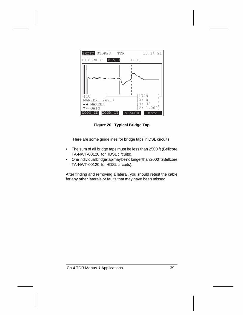
Bridge TapFigure 20 shows a typical bridge tap. The bridge tap begins at
835 feet and extends for 249 feet (“Distance” provides the begin-ning; “Marker” provides length). The bridge tap begins with thesteep downward slope; the lateral continues until the sharp upwardslope, or bump, which represents the open at the end.
Ch.4 TDR Menus & Applications 39
ZOOM_IN ZOOM_OT SEARCH more
[10 ]MARKER: 249.7 MARKER GAIN
[1729 ][0: 0 ][H: 32 ][V: 1.000]
FEETDISTANCE: 835.9
13:14:21TDRSHIFT STORED
Figure 20 Typical Bridge Tap
Here are some guidelines for bridge taps in DSL circuits:
• The sum of all bridge taps must be less than 2500 ft (BellcoreTA-NWT-00120, for HDSL circuits).
• One individual bridge tap may be no longer than 2000 ft (BellcoreTA-NWT-00120, for HDSL circuits).
After finding and removing a lateral, you should retest the cablefor any other laterals or faults that may have been missed.

40 SunSet xDSL Rev. C
Typical ShortFigure 21 shows a sample short occurring at 3355 feet. A
short is represented as a sharp dip in the waveform.
ZOOM_IN ZOOM_OT SEARCH more
[10 ]MARKER: 3325 MARKER GAIN
[6774 ][0: -6 ][H: 128 ][V: 1.000]
FEETDISTANCE: 3335
13:14:21TDRSHIFT STORED
Figure 21 Typical Short

Ch.4 TDR Menus & Applications 41
3.0 Performing a TDR Measurement
Follow this step-by-step procedure for making an TDR mea-surement with the SunSet xDSL:
1. Press the MENU key located on the second row of the keypad.2. Enter TDR. Note that TDR LED lights green.3. Configure this menu as follows. Refer to 1.0 in this chapter for
more information on each of the settings:
UNITS: ENGLISH or METRIC, as required.GAUGE: as specified by circuit cable.VP: as specified by circuit cable. If you don’t know the specificVP, keep the default setting provided by the SunSet xDSL.AVG: 1
4. Connect to the cable pair. A common method for connectinguses an RJ-45 to alligator clip cable. Plug the RJ-45 into the jackon the right side of the SunSet xDSL (labeled DMM/TDR/LINE).Use the alligator clips to clip directly to the cable pair. Refer toFigure 22.
TipRing
Figure 22 Connecting to the Cable Pair
5. Press the START (F3) key when you have completed yoursettings and have connected to the pair.
6. The waveform is now shown on the screen.7. Press the SEARCH (F3) key. The SunSet xDSL now begins to
look for the first fault. The screen shows SEARCHING while itscans the result.

42 SunSet xDSL Rev. C
ZOOM_IN ZOOM_OT SEARCH more
[10 ]MARKER: 960.2 MARKER GAIN
[1616 ][0: 0 ][H: 32 ][V: 1 ]
FEETDISTANCE:
13:14:21TDRSHIFT
FOUND970.2
Figure 23 Fault Found
8. When a fault is found, it appears on the screen. FOUND isdisplayed at the top right. Refer to Figure 23.
9. Use the left or right arrow keys to move the cursor to thebeginning of the reflection.
• The DISTANCE reading at top shows the location of the cursor.By placing the cursor at the beginning of the reflection, you haveidentified the fault location.
• If you need to adjust the display vertically, press the +OFFSETand -OFFSET F-keys.
10. If the reflection indicates a bridge tap, you’ll want to know thelength of the lateral. To find this, press MARKER (F1); you willprobably need to press the more (F4) key to find this option.Now use the right arrow key to move the dotted line, marker.Position the Marker at the end of the bridge tap. The MARKERreading at the bottom shows the distance between the Cursorand Marker.
11.To look past this bridge tap for other possible faults, either pressthe ZOOM_OT or PAGE-RGT keys. Refer to 2.2, FindingMultiple Faults in this chapter for more details.
43Ch.5 DMM Applications
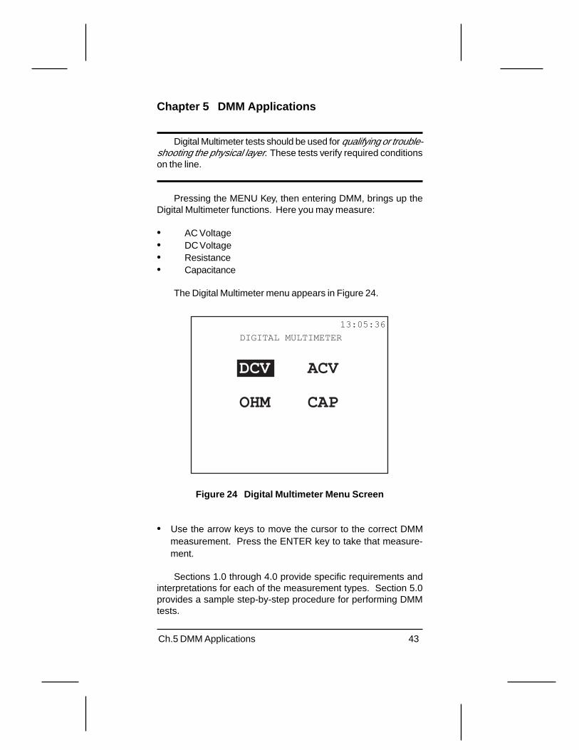
Chapter 5 DMM Applications
Digital Multimeter tests should be used for qualifying or trouble-shooting the physical layer. These tests verify required conditionson the line.
Pressing the MENU Key, then entering DMM, brings up theDigital Multimeter functions. Here you may measure:
• AC Voltage• DC Voltage• Resistance• Capacitance
The Digital Multimeter menu appears in Figure 24.
13:05:36
DCV ACV
OHM CAP
DIGITAL MULTIMETER
Figure 24 Digital Multimeter Menu Screen
• Use the arrow keys to move the cursor to the correct DMMmeasurement. Press the ENTER key to take that measure-ment.
Sections 1.0 through 4.0 provide specific requirements andinterpretations for each of the measurement types. Section 5.0provides a sample step-by-step procedure for performing DMMtests.

44 SunSet xDSL Rev. C
1.0 Measuring Capacitance
To measure capacitance, move the cursor to CAP; then pressthe ENTER key. The SunSet xDSL can measure from 1 nF to 1 µF.
13:14:21
CAP
DIST (FT) : 12898
TYPE : TIP_RNG
T_R:199.02 nFT_G:196.93 nFR_G:195.77 nF
RNG_GNDTIP_GNDTIP_RNG
Figure 25 Capacitance Screen
First, select the type of measurement to be performed:
• Press TIP_RNG (F1) to measure tip to ring.• Press TIP_GND (F2) to measure tip to ground.• Press RNG_GND (F3) to measure ring to ground.
Note : All three measurements are displayed simultaneously. How-ever, only the selected measurement is a live, updating result.
This measurement can be used to estimate loop length (tip-ring).
• This test measures the loop to the far end with an open circuit.• The bottom line provides the distance calculation; it is based on
the conversion factor, 83 nF/mile, as specified in ANSI T1.601Annex E.
• This calculation assumes there are no bridge taps present. Itwill add any bridge tap lengths to the total distance.
45Ch.5 DMM Applications
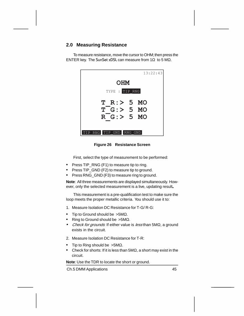
2.0 Measuring Resistance
To measure resistance, move the cursor to OHM; then press theENTER key. The SunSet xDSL can measure from 1Ω to 5 MΩ.
13:22:43
OHM
TIP_RNG
TYPE : TIP_RNG
T_R:> 5 MOT_G:> 5 MOR_G:> 5 MO
RNG_GNDTIP_GND
Figure 26 Resistance Screen
First, select the type of measurement to be performed:
• Press TIP_RNG (F1) to measure tip to ring.• Press TIP_GND (F2) to measure tip to ground.• Press RNG_GND (F3) to measure ring to ground.
Note : All three measurements are displayed simultaneously. How-ever, only the selected measurement is a live, updating result.....
This measurement is a pre-qualification test to make sure theloop meets the proper metallic criteria. You should use it to:
1. Measure Isolation DC Resistance for T-G/ R-G:
• Tip to Ground should be >5MΩ.• Ring to Ground should be >5MΩ.• Check for grounds: If either value is less than 5MΩ, a ground
exists in the circuit.
2. Measure Isolation DC Resistance for T-R:
• Tip to Ring should be >5MΩ.• Check for shorts: If it is less than 5MΩ, a short may exist in the
circuit.
Note : Use the TDR to locate the short or ground.

46 SunSet xDSL Rev. C
3.0 Measuring AC Voltage
DANGER!AC voltage can kill or cause serious injury.
To measure AC voltage, move the cursor to ACV; then pressthe ENTER key. The SunSet xDSL can measure up to 250 VAC.
TIP_RNG
13:26:34
ACVTYPE: TIP_RNG
T_R:0.033VT_G:0.014VR_G:0.003V
RNG_GNDTIP_GND
Figure 27 AC Voltage Screen
First, select the type of measurement to be performed:
• Press TIP_RNG (F1) to measure tip to ring.• Press TIP_GND (F2) to measure tip to ground.• Press RNG_GND (F3) to measure ring to ground.
Note : All three measurements are displayed simultaneously. How-ever, only the selected measurement is a live, updating result.
An AC Voltmeter should be used for troubleshooting the loop.It can identify unwanted power influence.
47Ch.5 DMM Applications
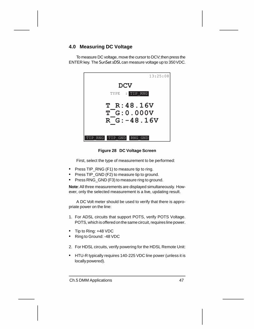
4.0 Measuring DC Voltage
To measure DC voltage, move the cursor to DCV; then press theENTER key. The SunSet xDSL can measure voltage up to 350 VDC.
TIP_RNG
13:25:08
DCVTYPE : TIP_RNG
T_R:48.16VT_G:0.000VR_G:-48.16V
RNG_GNDTIP_GND
Figure 28 DC Voltage Screen
First, select the type of measurement to be performed:
• Press TIP_RNG (F1) to measure tip to ring.• Press TIP_GND (F2) to measure tip to ground.• Press RNG_GND (F3) to measure ring to ground.
Note : All three measurements are displayed simultaneously. How-ever, only the selected measurement is a live, updating result.
A DC Volt meter should be used to verify that there is appro-priate power on the line:
1. For ADSL circuits that support POTS, verify POTS Voltage.POTS, which is offered on the same circuit, requires line power.
• Tip to Ring: +48 VDC• Ring to Ground: -48 VDC
2. For HDSL circuits, verify powering for the HDSL Remote Unit:
• HTU-R typically requires 140-225 VDC line power (unless it islocally powered).

48 SunSet xDSL Rev. C
5.0 DMM Application
Refer to this step-by-step sample procedure for performing aDMM measurement.
1. Press the MENU Key on the 2nd row of the keypad.2. Access DMM.3. Connect to the circuit. A common method is to use an RJ-45
to alligator clip cable. Plug the RJ-45 into the SunSet xDSL, atthe jack on the right side. Use alligator clips to clip directly ontothe copper pair at the NID, Cross-Box (B-Box), aerial or otheraccess points. Refer to Figure 29.
Ring
Tip
Figure 29 Connecting with RJ-45 to Alligator Clips
4. Use the arrow keys to move the cursor to the measurement youwant to take: then press the ENTER key.
5. Once you’re in a measurement screen, select the measurementtype:
• Press TIP_RNG (F1) to measure tip to ring.• Press TIP_GND (F2) to measure tip to ground.• Press RNG_GND (F3) to measure ring to ground.
Refer to the previous menu sections to learn the significanceand requirements for each of your results.

49Ch.6 Line Measurements
Chapter 6 Line Measurements
There are two types of Line Measurements, single-ended andpaired tests. Single-ended tests require one SunSet xDSL; theSunSet xDSL performs the test and takes the measurement fromone end of the cable. Refer to Figure 30.
Figure 30 Single-ended Test
The single-ended tests are described in Section 1. They are:
• Background Noise: checks for interfering services or noise.• Coil Detection: detects load coils in the circuit.• Impulse noise: checks for any transient noise sources.• Frequency generator and level meter; sends and receives test
tones.

50 SunSet xDSL Rev. C
Paired tests require two SunSet xDSLs, one on each end ofthe cable pair. There is a Controller unit, which sends the com-mands and takes the measurement. The Responder unit at the farend responds to commands by sending the tone or shorting thefar end. Refer to Figure 31.
Controller Responder
1. Sends Tone2. Shorts far end
Figure 31 Paired Tests
The dual-ended tests are:
• Insertion Loss: measures attenuation over the ADSL spectrumor for a single frequency.
• Signal to Noise: measures the signal to noise ratio over theADSL spectrum.
• Loop resistance: determines loop length by measuring loopresistance with a responder SunSet xDSL at the far end providinga short. This could also be a single-ended test with a short atthe far end.
51Ch.6 Line Measurements
1.0 Single-ended line tests
1.1 Background Noise
The Background Noise Test is used to detect interferers fromsuch sources as other digital services or AM radio. This is a single-ended test. It is recommended that the far end be terminated at100 Ω wherever possible.
You may test for noise at the full ADSL spectrum (22 kHz to1.6 MHz) or choose to place a filter which tests at ISDN BRI,HDSL, or ADSL frequencies. For ADSL testing, common inter-ferer templates can be placed on the screen so you may easilydetermine the type of interferer on your circuit.
1.1.1 PSD (ADSL DMT/CAP) Background Noise
The PSD (Power Spectral Density) background noise mea-surement includes the full frequency bandwidth for both ADSL,DMT, and CAP services.
Note : If this is the first time running the background noise test,you will need to calibrate your unit. Make sure the SunSet xDSL isdisconnected from the circuit, also remove the power supply con-nection. Press the MENU key, access LINE > CALIBRATION >BACKGROUND NOISE. Calibration may take up to 20 seconds.You should see a “Calibrate is Done!” message when finished. Ifthe calibration fails, try to run it again. Then you may proceed withyour background noise test.
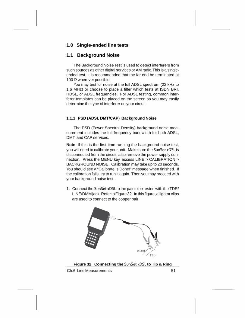
1. Connect the SunSet xDSL to the pair to be tested with the TDR/LINE/DMM jack. Refer to Figure 32. In this figure, alligator clipsare used to connect to the copper pair.
Tip
Ring
Figure 32 Connecting the SunSet xDSL to Tip & Ring

52 SunSet xDSL Rev. C
2. Press the MENU Key.3. Access LINE. The LINE LED will light green indicating the set
is performing a Line measurement.4. Access BACKGROUND NOISE.5. The setup screen appears in Figure 33.
08:21:36BACKGROUND NOISE
RxLEVEL : BRIDGE
PSD
TYPE : PSD
E START more
Figure 33 Background Noise Setup Screen
RxLEVELOptions: TERM (F1), BRIDGE (F2)
Set the receiver level for the SunSet xDSL:
• TERM (F1) places a 100 Ω termination on the received signal.This should be used for out-of-service testing only. When youhave selected TERM, you can use interferer templates in themeasurement screen.
• BRIDGE (F2) is a high-impedance mode that protects the livesignal. You may use this mode for in-service testing. When youhave selected BRIDGE, you may use noise masks in themeasurement screen.
Note : If you are connecting to a live circuit, be sure to selectBRIDGE mode before connecting.

53Ch.6 Line Measurements
TYPEOptions: PSD (F1), E (F2), F (more, F1), G (more, F2)
There are four different types of tests. Select the F-key corre-sponding to the desired test:
• PSD (F1): measures noise in the full ADSL DMT/CAP spec-trum: 13 kHz to 1.6 MHz.
• E (F2): measures noise in the spectrum for ISDN BRI. Filtersections:
High Pass: 3 dB down at 1 kHzLow Pass: 3 dB down at 50 kHzThe effective range for the SunSet xDSL is from 10 kHz.
• F (more, F1): measures noise in spectrum for HDSL. Filtersections:
High Pass: 3 dB down at 5 kHzLow Pass: 3 dB down at 245 kHzThe effective range for the SunSet xDSL is from 10 kHz.
• G (more, F2): measures noise in spectrum for ADSL. Filtersections:
High Pass: 3 dB down at 20 kHzLow Pass: 3 dB down at 1.1 MHz
Note : A 100 Ω to 135 Ω converter cable is required for E and Ffilter measurements.
6. For ADSL DMT/CAP, press PSD (F1). Then, press START (F3)to begin the measurement.
7. The results are shown in Figure 34.

54 SunSet xDSL Rev. C
08:22:08Template:NONE
GAIN MASKZOOM_IN TABLE more
-68-76-84-92
-100-108-116
[1600][4 ]X:(kHz) : 185.4 189.8 194.1Y:(dBm/Hz):-120.0 -120.0 -120.0
BACKGROUND NOISE
Figure 34 PSD Background Noise Results
The F-Keys in this screen are used as follows:
ZOOM_OUT/IN (F1): The ZOOM key sets the display scale forthe screen. Press ZOOM-OUT to display the full 1.6 MHz band-width on the screen. The resolution is 3 tones/pixel with the high-est noise value of the three tones plotted on the screen.
Note : When you have Zoomed in the full amount, two more F-keysare available: PG_LFT (more, F1) moves the screen display to theleft to display the lower tone frequencies. PG_RGT (more, F2) movesthe screen display to the right to display the higher tone frequencies.
MASK (F2): MASK places various templates of noise masks on thescreen to help you determine the interferer type. After pressing MASK,use the left and right arrow keys to scroll through the various tem-plate masks. The displayed mask is identified at the top of the screen.
CURSOR (F2): Press the CURSOR key to move the cursor on the dis-play. This can tell you the exact frequency of a disturber. After pressingCURSOR, use the left and right arrow keys to move the cursor. Checkthe Frequency reading at the bottom to know the exact frequency .
dBm and dBm/Hz (more, F1): These keys toggle the noise readingat the bottom of the screen. dBm is a pure power reading with areference to 1 milliwatt. The dBm/Hz measurement uses a refer-ence bandwidth of 4.3125 kHz for the reading.
55Ch.6 Line Measurements
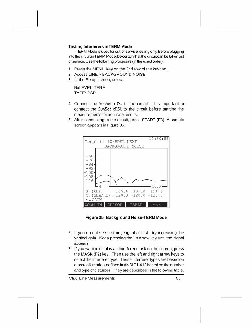
Testing Interferers in TERM ModeTERM Mode is used for out-of-service testing only. Before plugging
into the circuit in TERM Mode, be certain that the circuit can be taken outof service. Use the following procedure (in the exact order):
1. Press the MENU Key on the 2nd row of the keypad.2. Access LINE > BACKGROUND NOISE.3. In the Setup screen, select:
RxLEVEL: TERMTYPE: PSD
4. Connect the SunSet xDSL to the circuit. It is important toconnect the SunSet xDSL to the circuit before starting themeasurements for accurate results.
5. After connecting to the circuit, press START (F3). A samplescreen appears in Figure 35.
12:30:55
BACKGROUND NOISETemplate:10-HDSL NEXT
GAINCURSORZOOM_IN TABLE more
-68-76-84-92
-100-108-116
[1600][4 ]X:(kHz) : 185.4 189.8 194.1Y:(dBm/Hz):-120.0 -120.0 -120.0
Figure 35 Background Noise-TERM Mode
6. If you do not see a strong signal at first, try increasing thevertical gain. Keep pressing the up arrow key until the signalappears.
7. If you want to display an interferer mask on the screen, pressthe MASK (F2) key. Then use the left and right arrow keys toselect the interferer type. These interferer types are based oncross-talk models defined in ANSI T1.413 based on the numberand type of disturber. They are described in the folowing table.

56 SunSet xDSL Rev. C
Table 1 Interferer Type
Interferer Type Description 24-DSL NEXT 24 IDSL services in the same binder group 10-HDSL NEXT 10 HDSL services in the same binder group 4-T1 ADJ NEXT 4 T1 services in an adjacent binder group 24-T1 ADJ NEXT
24 T1 services in an adjacent binder group
10-ADSL DN NEXT
10 ADSL downstream services in the same binder group
10-ADSL UP NEXT
10 ADSL upstream services in the same binder group
T1.601 NEXT ANSI T1.601 Basic Rate ISDN in the same binder pair
10-DSL NEXT 10 IDSL services in the same binder group 10-ADSL NEXT 10 ADSL services in the same binder group 10-T1 ADJ NEXT
10 T1 services in an adjacent binder group
INT AMI 2M International 2.048 Mbps AMI signal (E1) ETSI BRA ETSI Basic Rate ISDN service ETSI HDSL ETSI HDSL service ADSL XTALK, ANSI 7,13
ADSL cross-talk ANSI loops 7 & 13
ADSL XTALK CSA 4
ADSL cross-talk, CSA loop 4
ADSL XTALK CSA 6
ADSL cross-talk, CSA loop 6
ADSL XTALK CSA 7
ADSL cross-talk, CSA loop 7
DSL NEXT IDSL service in the same binder group HDSL NEXT HDSL service in the same binder group G.DMT EC ADSL UP NEXT
G.DMT Echo-cancellation ADSL upstream service in the same binder group
G.DMT FDM ADSL UP NEXT
G.DMT Frequency division multiplexing ADSL upstream service in the same binder group
HDSL2 DN NEXT
HDSL2 downstream service in the same binder group
HDSL2 UP NEXT
HDSL2 upstream service in the same binder group
T1 NEXT T1 service in the same binder group EC ADSL DN Echo-cancellation downstream ADSL G.DMT FDM ADSL DN NEXT
G.DMT Frequency division multiplexing ADSL downstream service in the same binder group

57Ch.6 Line Measurements
These masks represent the common disturbers associatedwith DSL circuits. If you see an increase in the background noiselevel (Y-value), try scrolling through the various templates until atemplate matches the signal. This will help you to distinguish thenoise source on your circuit
8. You could also view your results in a tabular format. This formatprovides a list of the background noise measurements for eachtone level. To view the table, press TABLE (F3).
Testing Interferers in BRIDGE Mode
Caution!Bridge mode testing does not interfere with standard digitalline technologies such as T1 and E1. However, for complextechnologies using modem communications, like ADSL,bridging onto the circuit can cause a significant drop in thenoise margin causing the ADSL circuit to lose synchronizationand then resynchronize.
In BRIDGE Mode, the test set places a high impedance onthe received signal to protect the circuit. There will be a slight hiton the circuit, which may result in momentary alarms.
Follow this procedure (in the exact order):
1. Press the MENU Key on the 2nd row of the keypad.2. Access LINE > BACKGROUND NOISE.3. In the Setup screen, select:
RxLEVEL: BRIDGETYPE: PSD
4. Connect the SunSet xDSL to the circuit. It is important to connect theSunSet xDSL to the circuit before starting the measurements foraccurate results. Also, try to be as close to the transmitter as possible.For example, when checking the ATU-C Tx signal, connect as closeto the DSLAM as possible. You may clip directly onto the transmit pairwith alligator clips, or you could use a RJ-45 Y-adapter.
5. After connecting to the circuit, press START (F3). A samplescreen appears in Figure 36.
6. If you do not see a strong signal at first, try increasing the verticalgain. Keep pressing the up arrow key until the signal appears.
58 SunSet xDSL Rev. C
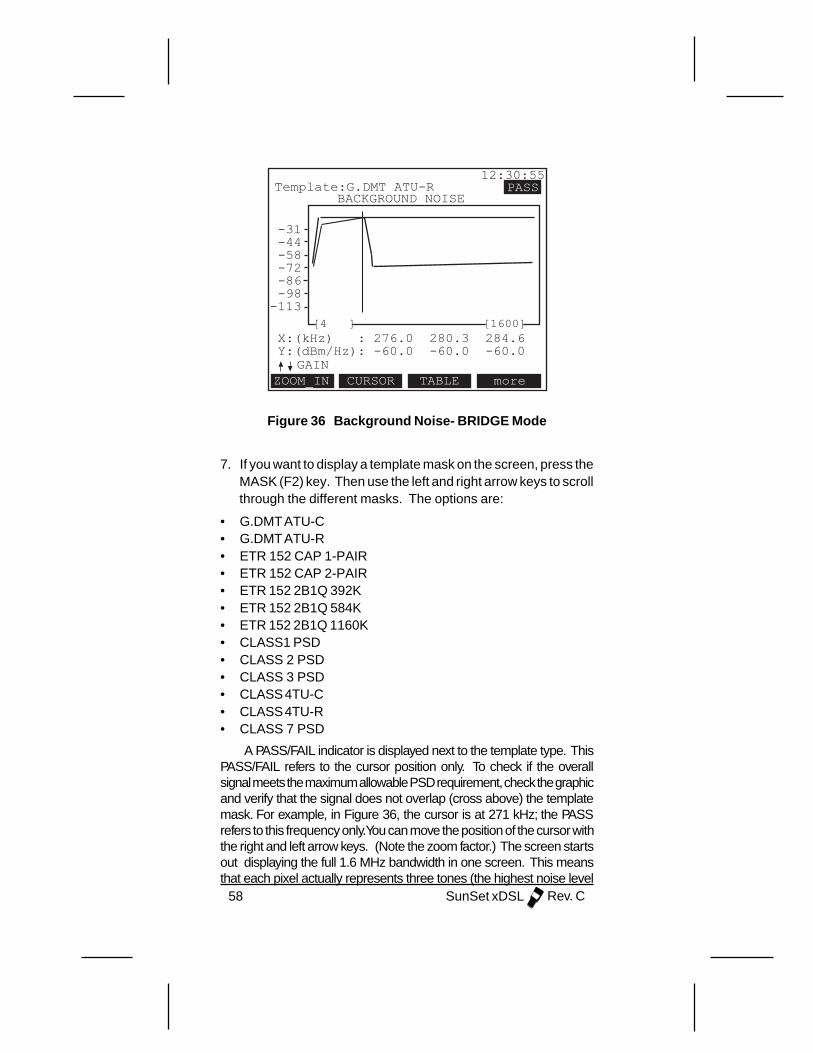
12:30:55
BACKGROUND NOISETemplate:G.DMT ATU-R
GAINCURSORZOOM_IN TABLE more
-31-44-58-72-86-98
-113[1600][4 ]
X:(kHz) : 276.0 280.3 284.6Y:(dBm/Hz): -60.0 -60.0 -60.0
PASS
Figure 36 Background Noise- BRIDGE Mode
7. If you want to display a template mask on the screen, press theMASK (F2) key. Then use the left and right arrow keys to scrollthrough the different masks. The options are:
• G.DMT ATU-C• G.DMT ATU-R• ETR 152 CAP 1-PAIR• ETR 152 CAP 2-PAIR• ETR 152 2B1Q 392K• ETR 152 2B1Q 584K• ETR 152 2B1Q 1160K• CLASS1 PSD• CLASS 2 PSD• CLASS 3 PSD• CLASS 4TU-C• CLASS 4TU-R• CLASS 7 PSD
A PASS/FAIL indicator is displayed next to the template type. ThisPASS/FAIL refers to the cursor position only. To check if the overallsignal meets the maximum allowable PSD requirement, check the graphicand verify that the signal does not overlap (cross above) the templatemask. For example, in Figure 36, the cursor is at 271 kHz; the PASSrefers to this frequency only. You can move the position of the cursor withthe right and left arrow keys. (Note the zoom factor.) The screen startsout displaying the full 1.6 MHz bandwidth in one screen. This meansthat each pixel actually represents three tones (the highest noise level

59Ch.6 Line Measurements
for those three tones is displayed). For better resolution, press theZOOM_IN (F1) key. You can use the Page-Right and Page-Left keys toshift the screen display from the higher and lower tones.
8. You could also view your results in a tabular format. This formatprovides a list of the background noise measurements for eachtone level. To view the table, press TABLE (F3).
1.1.2 Other Background Noise TestsIn addition to the ADSL DMT/CAP background noise test described
in section 1.1.1, you also may test background noise in the ISDN BRI,HDSL, or ADSL spectrums. Refer to the following procedure:
1. Press the MENU Key on the 2nd row of the keypad.2. Enter LINE.3. Enter BACKGROUND NOISE.4. Select the Rx Level:
• TERM (F1) places a 100 Ω termination on the received signal.This should be used for out-of-service testing only.
• BRIDGE (F2) is a high-impedance mode that protects the livesignal. You may use this mode for in-service testing.
Note : If you are connecting to a live circuit, be sure to selectBRIDGE mode before connecting.
5. Select the type.
• E (F2): measures noise in the spectrum for ISDN BRI. Filtersections:
High Pass: 3 dB down at 1 kHzLow Pass: 3 dB down at 50 kHz
• F (more, F1): measures noise in spectrum for HDSL. Filtersections:
High Pass: 3 dB down at 5 kHzLow Pass: 3 dB down at 245 kHz
• G (more, F2): measures noise in spectrum for ADSL. Filtersections:
High Pass: 3 dB down at 20 kHzLow Pass: 3 dB down at 1.1 MHz
Note: Sunrise Telecom recommends a 100 Ω to 135 Ω converter cablefor E and F filter measurements. Effective range is from 10 kHz.
6. Press START (F3). The results display the filter type and thenoise reading.

60 SunSet xDSL Rev. C
1.2 Level Meter
The Level Meter can be used to measure the frequency andlevel of a received tone. The Level Meter can be connected to aconventional TIMS tone generator or a frequency oscillator at thefar end. The Level Meter measures the highest power frequency.Refer to Figure 37.
To enter level meter:
1. Press the MENU key.2. Access LINE > LEVEL METER. A sample screen appears in
Figure 37.
11:05:34
LEVEL METER
FREQ. (kHz) : 40
LEVEL (dBm) : -22.8
Figure 37 Level Meter

61Ch.6 Line Measurements
1.3 Frequency Generator
You may use the SunSet xDSL to send a tone at a specifiedfrequency and level. You can use a tone analyzer at the far end tomeasure the level and frequency. To send a tone, refer to thefollowing procedure:
1. Press the MENU key.2. Access LINE > FREQUENCY GENERATOR. A sample screen
appears in Figure 38.
05:43:00
FREQUENCY GENERATOR
FREQ (kHz) : 10.0
dBm : 1
TRANSMITTING ...
+1 -1 START more
Figure 38 Frequency Generator
You may adjust the frequency and level of your tone.
FREQRange: 10 to 1600 kHz
• Use the F-keys (F1) and (F2) to adjust the tone frequency.• The following increment/decrement values are available (press
the more key): +/- 0.1, +/-1, +/- 10, +/- 100.
dBmRange: -10 to +26 dBm
• Use the F-keys +1 (F1) and -1 (F2) to adjust the tone level.
3. Once you have set your frequency and level, press the START(F3) key. The test set will transmit the specified tone until youescape out of the screen.

62 SunSet xDSL Rev. C
1.4 Coil Detection
The Coil Detection test is a quick and easy way to check forload coils on your cable. The Coil Detection test does not providea location for the load coils (you will need to use the TDR for this)but it will show you if any are present.
The typical spacing for load coils is every 6000ft.
What is a Load Coil?Over long cable lengths, upper voiceband signals are attenu-
ated due to increased capacitance. Phone companies deal withthese long loops (greater than 18,000 feet) by placing load coils atregular intervals. A load coil is an inductor, typically 88 mH. Loadcoils are placed at regular intervals on cable longer than 18,000feet. The first appears 3,000 feet from the C.O. or exchange. Then,load coils are placed every 6,000 feet.
Loaded cable enables transmission between 300 Hz to 3.1kHz at a higher power level than unloaded cable. However, after 4kHz, the power level drops below that of an unloaded circuit. Theresult is that higher frequencies (>4 kHz) are more heavily attenu-ated with load coils. Therefore, high frequency signals, like ADSL,are severely attenuated by load coils
Performing a Coil Detection TestFollow this procedure to perform the Coil Detection test. For
accurate results, the load coils on the circuit should comply tostandard spacing rules.
1. Connect the SunSet xDSL to the circuit with the TDR/LINE/DMMjack. A sample diagram is shown in Figure 39. Plug an RJ-45into the SunSet xDSLs TDR/TIMS/DMM jack. Connect thealligator clips at the other end directly to the cable pair. Theremust be an open at the far end for this test.
Tip
Ring
Figure 39 Connecting the SunSet xDSL to the Cable Pair

63Ch.6 Line Measurements
2. Press the MENU Key.3. Access LINE. The LINE LED will light green indicating the set
is performing a Line measurement.4. Cursor down to COIL DETECTION. Press the ENTER key.5. Refer to the top row on the screen to read the status messages.
There are two states:
• PROCESSING: The test set has finished initializing and is inthe process of taking the measurement. The processing stagetakes approximately 20 seconds.
• COMPLETED: The test set has completed the measurementand now displays the results. These results do not constantlyupdate; you will need to press the RESTART (F4) key to restartthe test and update the results.
6. Refer to the graph in Figure 40. The plot measures impedance(y-axis) by frequency (x-axis).
13:08:21>COMPLETED COMPLETED<
COIL DETECTION
Possible Coils: 3
STORE RESTART
Figure 40 Coil Detection
• A load coil causes a change in impedance. This is displayed on thegraph. A big dip in the impedance (y) represents a load coil.
• The number of load coils is displayed at the bottom of thescreen. In Figure 40, there are three dips in the graph indicatingthree load coils.
• The screen display does not update. Press the RESTART (F4)key to retake the measurement.

64 SunSet xDSL Rev. C
Removing Load CoilsThe Coil Detection test is the fastest method for determining
the presence of load coils. If this test proves the presence of loadcoils, you will need to use the SunSet xDSLs TDR to determine theexact location of the load coils for removal. The safest way toensure that all load coils are removed is to remove the first loadcoil, then run the test again to check if there are more farther downthe cable. Continue this same process: find a load coil, remove it,then check for another one. Remember: all load coils must beremoved for DSL transmission.
1.5 Impulse Noise
The SunSet xDSLs Impulse Noise feature detects impulse noisespikes on the signal and keeps a running count of the number ofimpulse events over time. Impulse noise is defined as a randompulse whose amplitude is much higher than that of backgroundnoise. IEEE defines impulse noise as any burst of noise thatproduces a voltage exceeding the RMS value of the backgroundor quantizing noise by more than 12 dB [IEEE 743-1995].
Use the following procedure to test for impulse noise:
1. Connect the SunSet xDSL to the circuit with the TDR/LINE/DMMjack. A sample diagram is shown in Figure 41. Plug an RJ-45into the SunSet xDSLs TDR/TIMS/DMM jack. Connect thealligator clips at the other end directly to the cable pair.
Tip
Ring
Figure 41 Connecting the SunSet xDSL to the Cable Pair
2. Press the MENU key.3. Access LINE. The LINE LED lights green indicating the set is
in the Line testing mode.4. Cursor down to IMPULSE NOISE. Press the ENTER key.

65Ch.6 Line Measurements
5. The Impulse Noise Setup screen appears. Refer to Figure 42.
02:20:36
IMPULSE NOISE
THRESHOLD : 60 dBrnDELTA : 4 dBMAX COUNT : 998DEAD TIME : 125.0msTIMER : CONTINU
+1 moreSTART-1
Figure 42 Impulse Noise Setup
This screen contains the following setup parameters:
ThresholdRange: 50 dBrn to 100 dBrrn
This defines the lower threshold value for an impulse noiseevent. When the test set detects noise above this threshold, theSunSet xDSL records it as an impulse noise event.
• Use the +1 (F1) and -1 (F2) keys to adjust this value.• Press more (F4) to access +10 (F1) and -10 (F2).
DeltaRange: 2 to 6
Delta sets the range for the Low, Middle, and High event counts.In Figure 42, the threshold is set for 60 dBrn; this is the Low count.The delta value is set for 4. Therefore, the low count refers to anynoise between 60 and 64; the middle count refers to any noisebetween 64 and 68. High refers to anything above 68 dBrn.
• Use the +1 (F1) and -1 (F2) keys to adjust this value.
66 SunSet xDSL Rev. C
Max CountRange: 1 to 9999
Max count refers to the maximum number of impulse eventsthat will be counted during a single measurement.
• Use the +1 (F1) and -1 (F2) keys to adjust this value.• Press more (F4) to access +10 (F1) and -10 (F2).• Press more (F4) again to access +100 (F1), -100 (F2)• Press more (F4) again to access +1000 (F1), -1000 (F2)
Dead TimeRange: 0.1 ms to 255 ms
Dead Time refers to the measurement delay after the unit de-tects the initial impulse. Dead Time begins as soon as the SunSetxDSL detects the initial impulse. The test set resumes measuringevents after the dead time has elapsed. This prevents the SunSetxDSL from measuring the same impulse noise spike multiple times.
TimerRange: 1 to 999, Continu
Timer sets the duration time of the measurement. You can runyour test from 1 to 999 minutes. As soon as you start the mea-surement, the elapsed time starts counting up to this value. Whenit reaches the timer value, the test stops. To run a continuous test,press the more (F4) key several times, then select CONTINU (F1).
When you have completed your settings, press the START(F3) key to begin the test. A sample results screen is shown inFigure 43.
Press RESTART (F4) to restart the measurement and resetall counters to zero.
Press STORE (F3) to save your results.
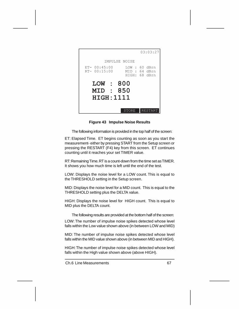
67Ch.6 Line Measurements
03:03:27
IMPULSE NOISE
ET- 00:45:00RT- 00:15:00
LOW : 60 dBrnMID : 64 dBrnHIGH: 68 dBrn
LOW : 800MID : 850HIGH:1111
STORE RESTART
Figure 43 Impulse Noise Results
The following information is provided in the top half of the screen:
ET: Elapsed Time. ET begins counting as soon as you start themeasurement- either by pressing START from the Setup screen orpressing the RESTART (F4) key from this screen. ET continuescounting until it reaches your set TIMER value.
RT: Remaining Time. RT is a count-down from the time set as TIMER.It shows you how much time is left until the end of the test.
LOW: Displays the noise level for a LOW count. This is equal tothe THRESHOLD setting in the Setup screen.
MID: Displays the noise level for a MID count. This is equal to theTHRESHOLD setting plus the DELTA value.
HIGH: Displays the noise level for HIGH count. This is equal toMID plus the DELTA count.
The following results are provided at the bottom half of the screen:
LOW: The number of impulse noise spikes detected whose levelfalls within the Low value shown above (in between LOW and MID)
MID: The number of impulse noise spikes detected whose levelfalls within the MID value shown above (in between MID and HIGH).
HIGH: The number of impulse noise spikes detected whose levelfalls within the High value shown above (above HIGH).
68 SunSet xDSL Rev. C
2.0 Controller tests
There are three tests listed within the Controller menu: InsertionLoss, Signal to Noise, and Loop Resistance. These are paired testsand require another SunSet xDSL in responder mode at the far end.Section 2.0 outlines the controller set for each application. Section3.0 discusses how to set the xDSL for responder mode.
2.1 Insertion Loss
Insertion loss testing is an excellent pre-qualification tool. Itmeasures attenuation using two SunSet xDSLs: the Responder unitsends the tones from the far end, while the Controller SunSet xDSLconducts the measurement. It provides loss characteristics up to1.6 MHz, including the entire ADSL band (both DMT and CAP).Single frequency measurements are also available. It can be usedto qualify HDSL transmission (196 kHz), T1 (772 kHz), U-Inter-face ISDN (40 kHz), etc.
2.1.1 Insertion Loss for DMT/CAP Freq. BandBoth ADSL CAP and DMT frequencies are covered with the
ADSL PSD (Power Spectral Density) test. For DMT ADSL, theattenuation measurement must be made for the entire DMT fre-quency band: 22 kHz to 1.1 MHz. The SunSet xDSL measuresbeyond this range to 1.6 MHz to test for CAP ADSL. The Re-sponder unit sends the frequency sweep tones; the Controller unittakes the measurement.
Follow these steps to configure the Controller unit:
Note: If this is the first time running the insertion loss test, or after an NVRAM ERASE, you will need to calibrate your unit. Make sure the SunSetxDSL is disconnected from the circuit. Press the MENU key; accessLINE >CALIBRATION > INSERTION LOSS. Calibration may take upto 20 seconds. You should see a “Calibrate is Done!” message whenfinished. Then you may proceed with your insertion loss test.
1. Connect the SunSet xDSL to the circuit with the TDR/LINE/DMMjack. Refer to Figure 44. In this figure, alligator clips are usedto connect to the tip & ring wires.
2. Press the MENU Key.3. Access LINE. The LINE LED will light green indicating the set
is performing a Line measurement.4. Access CONTROLLER > INSERTION LOSS > ADSL PSD.
ADSL PSD includes both the DMT and CAP bandwidth.

69Ch.6 Line Measurements
Tip
Ring
Figure 44 Connecting the SunSet xDSL to Tip & Ring
5. The top line of the screen shows the unit’s status. There arethree possible states:
• Processing: The Responder has received the command and isin the process of sending a tone.
• Completed: The Responder has carried out the command.• Failed: The Responder has failed to reply to the command.
6. The results show a Level vs. Frequency plot. Refer to Figure 45.
13:08:21>PROCESSING COMPLETED>
INSERTION LOSS
Freq. (kHz) : 500Loss ( dB) : 44
[22 ] [768 ]
PG_LFT PG_RGT TABLE RESTART
Figure 45 ADSL PSD Insertion Loss Result
• ANSI T1.413 specifies insertion loss results for various loopsand impaired lines. Variables in these results include: wiregauge, impairments, and temperature.

70 SunSet xDSL Rev. C
• To find the exact insertion loss for a particular frequency, refer tothe results provided below the graph. Use the right and left arrowkeys to move the cursor. Check the frequency reading (Freq. kHz)until the cursor has reached the desired frequency. Then refer tothe loss reading (Loss dB) for that particular frequency.
The F-Keys in this screen are:
PG_LFT (F1) and PG_RGT (F2): These keys move the screen dis-play to the left or right. The following screen displays are available:
• 22 kHz to 768 kHz• 397 kHz to 1143 kHz• 772 kHz to 1518 kHz• 854 kHz to 1600 kHz
TABLE (F3): This key displays the loss readings in a table formatfor each particular tone. A sample screen is provided in Figure 46.
13:08:21>PROCESSING CONNECTED>
INSERTION LOSSkHz LEVEL kHz LEVEL kHz LEVEL798 57 802 57 806 57811 58 815 58 819 58824 58 828 58 832 59837 59 841 59 845 59850 60 854 60 858 60863 60 867 61 871 61875 61 880 61 884 62888 62 893 62 897 63901 63 906 63 910 63914 64 919 64 923 64
RESTARTGRAPHPAGE-DNPAGE-UP
Figure 46 Insertion Loss - Table format
RESTART (F4): This key restarts the measurement and updatesthe results.
BRG_TAP (F1): This key searches for and reports any bridge tapson the cable pair.
Note: You may store and print both the Insertion Loss graphic andtable results to a serial port printer. Refer to the Printing & Storagechapter for more details.

71Ch.6 Line Measurements
Detecting Bridge Taps with Insertion LossInsertion loss may be used as an alternative method for de-
tecting bridge taps on the cable pair. Insertion loss can be advan-tageous because it allows you to test a greater range than a TDR.This method shows the presence of bridge taps and can calculatethe approximate length. However, a TDR is still needed to deter-mine the exact location.
1. In the Insertion Loss screen, press BRG_TAP (F1). You mayneed to press more (F4) first.
2. The set looks for any dips in the frequency curve. A typicalinsertion loss result without any faults is a linear curve slopingdownward. A bridge tap will appear as a subtle dip in the curve.The bridge tap length affects different frequencies.
3. If the set finds a bridge tap, it moves the cursor to the dip. Itreports the length of the bridge tap (BT Ln) in feet at the bottomof the screen. Note that this is the length of the bridge tap, notthe location.
4. The set calculates the length based on the Vp (Velocity ofPropagation) setting shown above. The default setting is 0.66.If you know the specific Vp setting, use the +VP (F2) and -VP(F3) keys to adjust the value. The Vp setting will affect thelength calculation for the bridge tap. Refer to Chapter 4 for moredetails on Vp.
5. Insertion loss can detect multiple bridge taps on the cable pair.After it has detected the first bridge tap, simply press BRG_TAP(F1) again to detect the next tap.
Note : Insertion loss checks for dips in the frequency curve. Thesedips could be caused by other impairments or cable factors. Youshould verify the presence of a bridge tap with a TDR.

72 SunSet xDSL Rev. C
2.1.2 Single Frequency Insertion Loss Tests
The other Insertion Loss tests measure loss at one particularfrequency. Each can be used to qualify the span for a particulartransmission type (i.e HDSL, T1, ISDN BRI).
Follow these steps to configure the Controller unit:
1. Connect the SunSet xDSL to the span.2. Press the MENU Key.3. Access LINE > CONTROLLER > INSERTION LOSS.4. Cursor down to the desired Insertion Loss test. Press ENTER.
The tests should be used as follows:
• HDSL (European): 150 kHz• HDSL, 2 pair T1: 196 kHz• HDSL, 1 pair T1: 392 kHz• HDSL E1: 260 kHz• ISDN BRI at the U-Interface: 40 kHz• ISDN BRI at the S-Interface: 96 kHz• DDS: 82 kHz• T1: 772 kHz• E1: 1.024 MHz
5. The results show the single frequency tested and the dB lossat this frequency. Refer to Figure 47.
13:08:21>PROCESSING CONNECTED>
INSERTION LOSS
FREQ (kHz) : 196
LOSS (dB) : 0.03
RESTART
Figure 47 Single Frequency Insertion Loss
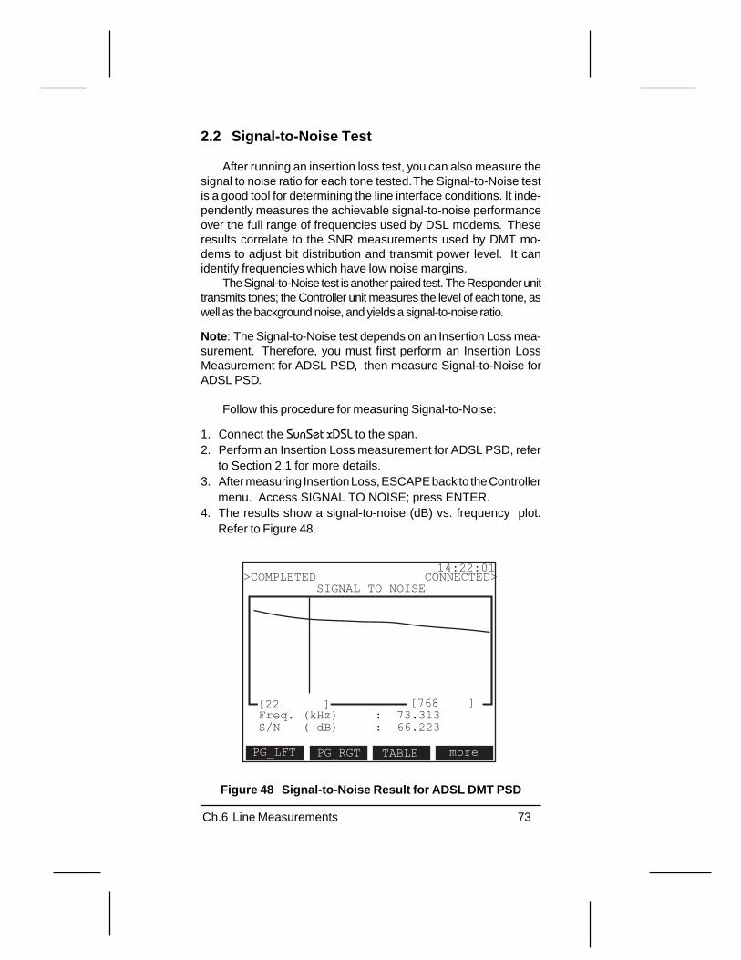
73Ch.6 Line Measurements
2.2 Signal-to-Noise Test
After running an insertion loss test, you can also measure thesignal to noise ratio for each tone tested. The Signal-to-Noise testis a good tool for determining the line interface conditions. It inde-pendently measures the achievable signal-to-noise performanceover the full range of frequencies used by DSL modems. Theseresults correlate to the SNR measurements used by DMT mo-dems to adjust bit distribution and transmit power level. It canidentify frequencies which have low noise margins.
The Signal-to-Noise test is another paired test. The Responder unittransmits tones; the Controller unit measures the level of each tone, aswell as the background noise, and yields a signal-to-noise ratio.
Note : The Signal-to-Noise test depends on an Insertion Loss mea-surement. Therefore, you must first perform an Insertion LossMeasurement for ADSL PSD, then measure Signal-to-Noise forADSL PSD.
Follow this procedure for measuring Signal-to-Noise:
1. Connect the SunSet xDSL to the span.2. Perform an Insertion Loss measurement for ADSL PSD, refer
to Section 2.1 for more details.3. After measuring Insertion Loss, ESCAPE back to the Controller
menu. Access SIGNAL TO NOISE; press ENTER.4. The results show a signal-to-noise (dB) vs. frequency plot.
Refer to Figure 48.
14:22:01
Freq. (kHz) : 73.313S/N ( dB) : 66.223
[22 ] [768 ]
SIGNAL TO NOISE
PG_RGTPG_LFT TABLE
>COMPLETED CONNECTED>
more
Figure 48 Signal-to-Noise Result for ADSL DMT PSD

74 SunSet xDSL Rev. C
Notes:
• This test measures noise in a 22 kHz to 1.6 MHz spectrum. Thefirst screen displays tones from 22 Hz to 768 kHz. The secondscreen displays tones from 344 kHz to 1.6 MHz. Use thePG_LFT (F1) and PG_RGT (F2) keys to change between thesetwo screens.
• To learn the exact S/N reading at a particular frequency, referto the results below the graph. Use the left and right arrow keysto move the cursor to the desired frequency (as read at Freq.kHz). The S/N (dB) shows the exact signal to noise ratio for thatfrequency.
• A vertical double dot will appear above the signal to noisereading when the background noise measured is < -120 dBm/Hzor the Signal to Noise ratio is <0 dB.
• If the measured background noise is < -120 dBm/Hz, it will beindicated by “NSE < -120 dBm/Hz”, displayed towards thebottom of the screen.
• Tabular results maybe viewed by pressing the TABLE (F3) key.• The S/N value is shown in reverse video if the S/N ratio is < 0 dB
or if the background noise is < -120 dBm/Hz.

75Ch.6 Line Measurements
2.3 Loop Resistance Test
The Loop Resistance Test provides an estimated loop length.It is measured with a short at the far end. This test can be a single-ended test if a short can be manually placed at the far end. LoopResistance could also be a paired test with the Responder unitproviding the short at the far end.
A loop resistance measurement can be used to:
• Estimate Loop Length: Loop Resistance can be used to esti-mate loop length. The SunSet xDSL provides the calculation foryou, based on ANSI T1.601, Annex G. This conversion factoris based on cable type, AWG (cable width), and temperature.
• Verify circuit has acceptable loop resistance (tip-ring). Theseare maximum values with the far end shorted.
HDSL Requirement: 900 ΩADSL Requirement: 1300 Ω
To measure loop resistance, follow these steps:
1. Connect the SunSet xDSL to the circuit. Refer to Figure 49. Inthis figure, alligator clips are used to connect to the tip & ring ata cross-box. There must be a short at the far end to performthis measurement.
TR
RT
Cross-Box, B-Box
C.O.
Short at Far-End
Figure 49 Connecting the SunSet xDSL to the Circuit toMeasure Resistance

76 SunSet xDSL Rev. C
Note : You may also use another SunSet xDSL to provide the shortat the far end. If you do so, it is recommended to wait 10 secondsbefore restarting the measurement due to communication betweenthe two units.
2. Press the MENU Key.3. Access LINE. The LINE LED will light green indicating the set
is performing a Line measurement.4. Access CONTROLLER > LOOP RESISTANCE. Press the
ENTER key. The screen is shown in Figure 50.
12:11:09
RESISTANCE
0.7584 kohmDIST(22 AWG): 23409DIST(24 AWG): 14718DIST(26 AWG): 9256
<< FEET >>
TIP_RING moreRNG_GNDTIP_GND
TYPE : TIP_RINGTEMP (F): 70
Figure 50 Loop Resistance Screen
You need to configure two settings for this measurement:
TYPEOptions: TIP_RNG (F1), TIP_GND (F2), RNG_GND (F3)
Press the F-key corresponding to the measurement you wantto make: tip-ring, tip-ground, or ring-ground.
TEMP (F)Use the INC (F1) and DEC (F2) keys to select the temperature.
• Remember the far end must be shorted in order to run this test.If it is not shorted, the screen will read “OPEN” and will notprovide a measurement.

77Ch.6 Line Measurements
3.0 Responder testing
The paired tests (Insertion Loss, Signal to Noise, and LoopResistance) require a SunSet xDSL in Responder mode at the farend. This unit responds to commands from the controller unit.
To set up the Responder unit, refer to the following steps:
1. Connect the SunSet xDSL to the span with the TDR/LINE/DMMjack. A common method is to use an RJ-45 to alligator/probe-clip cable. Clip directly onto the copper pair with the alligatorclips; plug the RJ-45 into the SunSet xDSL.
2. Press the MENU Key.3. Access LINE. The LINE LED will light green indicating the set
is performing a Line measurement.4. Access RESPONDER. Note that the RESPOND LED lights
green indicating the set is in responder mode.5. The SunSet xDSL will now automatically respond to commands
from the Controller unit. You must remain in this screen torespond to commands. These commands and the unit’s statusare displayed on the screen in Figure 51.
12:14:58LINE MEASUREMENTMODE: RESPONDER
LINE : CONNECTEDCOMMAND : INSERTION LOSSSTATUS : COMPLETED
< Press ESC to Exit >
Figure 51 Responder Mode

78 SunSet xDSL Rev. C
There are three lines of information on the Responder Modescreen:
LINE: shows the connection with the Controller unit. LINE displays IDLE(when it’s not receiving anything from the Controller) or CONNECTED(when it is receiving messages from the Controller).
COMMAND: refers to the type of command received from theController unit. Here, the Controller unit is running an InsertionLoss test.
STATUS: shows the Responder unit’s status. This can be either:
• Received: The set received the command from the controllerunit.
• Processing: The set is in the process of responding to thecontroller’s commands.
• Completed: The set responded to the controller’s command.

79Ch.6 Line Measurements
4.0 Remote Auto Test
Sunrise Telecom and Turnstone Inc. have partnered in the de-velopment of an automated two-ended testing solution to help sim-plify the installation and maintenance of DSL services. This al-lows for the SunSet xDSL and Copper CrossConnect™ CX100 tocommunicate with each other across a copper pair. The result isan automated, two-ended testing of the copper pair that is provid-ing the DSL service.
The connection between the CX100 (COTE, Central OfficeTest Equipment) and the SunSet xDSL (FETE, Far End Test Equip-ment) is simply the copper pair. Refer to Figure 52. The two-endedtests that are run are used to qualify this pair to for DSL service.
Copper Pair
TurnstoneCX100COTE
SunSet xDSLFETE
Figure 52 Connection from CX100 to SunSet xDSL
Use the following procedure to run the Remote Auto Test.
Note : For this two-ended testing application, the Turnstone CX100device must be in INSTALL MODE.
1. Connect the SunSet xDSL to the cable pair. You will typically dothis with the RJ-45 to alligator clips cable.
2. Press the MENU key.3. Access LINE > REMOTE AUTO TEST. Refer to Figure 53.

80 SunSet xDSL Rev. C
14:03:19
VIEW START
ELAPSED TIME : 00:00:00REMAINING TIME : 00:06:10
COTE TESTINGFETE TESTING256 TONE TESTING
COTE RESULT :FETE RESULT :
REMOTE AUTO TEST
Figure 53 Remote Auto Test Screen
4. To begin the test, press the START (F4) key. You will see aseries of messages at the top of the screen indicating the statusof the test as it is progressing through the measurements. Youwill first see a detection of the CX100 device and then ahandshaking process to time synch the two devices. Then thetests will begin.A. The VIEW (F1) key will allow you to access any stored
results from previous tests.
5. On the screen, you will see an Elapsed Time, Remaining Time,COTE TEST, FETE TEST, 256 TONE SWEEP, COTE RE-SULT, and FETE RESULT displayed. Refer to Figure 53. Thescreen displays the results as the test progresses.
The tests that are run are as follows:
• COTE Testing: This is in two parts. For the first 30 seconds, theFETE places an OPEN on the circuit. The COTE will then run anumber of tests with this condition on the cable pair. For the next20 seconds, the FETE places a SHORT on the cable pair and theCOTE will run the appropriate tests for this condition.
• FETE Testing: During the next 45 seconds, the COTE placesan OPEN on the pair, and the FETE will run the appropriate testson the cable pair (Primarily Background Noise).

81Ch.6 Line Measurements
• 256 Tone Sweep. Immediately following the FETE Testing, theFETE begins sending the 256 Tone Sweep while the COTEtakes a measurement of each tone for 1 second per tone.
• Results Exchange. At the end of the 256 Tone Sweep, theresults are exchanged and then displayed on the SunSet xDSL.
6. At the end of the test, you will see the final results that have beenexchanged between the COTE and the FETE. These resultsindicate the status of the test that was run. You may see aPASS, FAIL, MARGINAL, or UNEXPECTED ERROR result forthe test from either end of the circuit. Refer to Figure 54.
14:09:29
STORE RESTART
ELAPSED TIME : 00:00:00REMAINING TIME : COMPLETED
COTE TESTING - DONEFETE TESTING - DONE256 TONE TESTING - DONE
COTE RESULT : PASSFETE RESULT : PASS
REMOTE AUTO TEST
>TEST COMPLETED <
PAGE-UP PAGE-DN
Figure 54 Remote Auto Test Completed Screen
Options: STORE (F1), PAGE-UP (F2), PAGE-DN (F3), RESTART (F4)
STORE: To store, view, or print a result, press the STORE key.This displays the STORED RESULTS page, where you will seethe EDIT, VIEW, or PRINT Function keys.
• Storage and Printing of Results: The SunSet xDSL can store upto 10 results for the Remote Auto Test feature, with a LABEL anda TICKET, just like the storage for any other function in the testset. It stores all of the Background Noise measurements per-formed, as well as the final results of the test from both ends of thecircuit (PASS, FAIL, MARGINAL, or UNEXPECTED ERROR).The CX100 device also stores the results obtained from the testin its management system for the user to retrieve remotely.
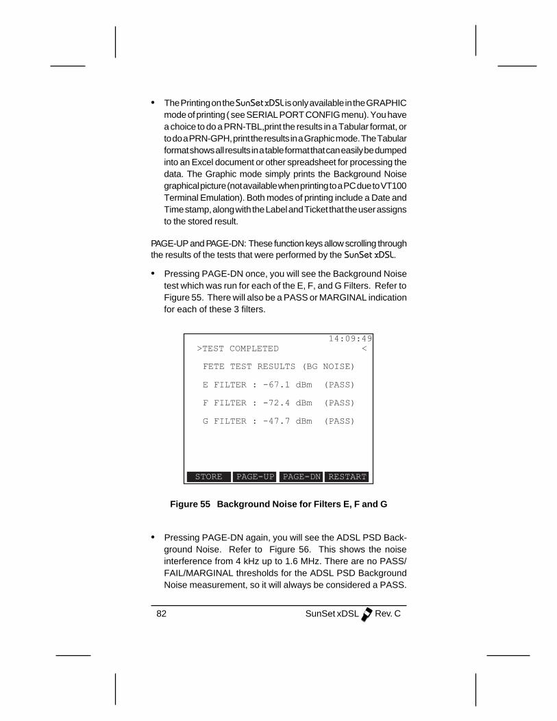
82 SunSet xDSL Rev. C
• The Printing on the SunSet xDSL is only available in the GRAPHICmode of printing ( see SERIAL PORT CONFIG menu). You havea choice to do a PRN-TBL,print the results in a Tabular format, orto do a PRN-GPH, print the results in a Graphic mode. The Tabularformat shows all results in a table format that can easily be dumpedinto an Excel document or other spreadsheet for processing thedata. The Graphic mode simply prints the Background Noisegraphical picture (not available when printing to a PC due to VT100Terminal Emulation). Both modes of printing include a Date andTime stamp, along with the Label and Ticket that the user assignsto the stored result.
PAGE-UP and PAGE-DN: These function keys allow scrolling throughthe results of the tests that were performed by the SunSet xDSL.
• Pressing PAGE-DN once, you will see the Background Noisetest which was run for each of the E, F, and G Filters. Refer toFigure 55. There will also be a PASS or MARGINAL indicationfor each of these 3 filters.
14:09:49
FETE TEST RESULTS (BG NOISE)
E FILTER : -67.1 dBm (PASS)
F FILTER : -72.4 dBm (PASS)
G FILTER : -47.7 dBm (PASS)
>TEST COMPLETED <
STORE PAGE-UP PAGE-DN RESTART
Figure 55 Background Noise for Filters E, F and G
• Pressing PAGE-DN again, you will see the ADSL PSD Back-ground Noise. Refer to Figure 56. This shows the noiseinterference from 4 kHz up to 1.6 MHz. There are no PASS/FAIL/MARGINAL thresholds for the ADSL PSD BackgroundNoise measurement, so it will always be considered a PASS.

83Ch.6 Line Measurements
14:09:49>TEST COMPLETED <
STORE PAGE-UP PAGE-DN RESTART
FETE TEST RESULTS (BG NOISE)
-10--27--34--51--68--85-
-102-[4 ] [1600]
X(kHz) :4.3 8.6 12.9Y(dBm/Hz):-120.0 -120.0 -120.0
GAIN
Figure 56 ADSL PSD Background Noise Measurement
RESTART: To Restart the test, simply press the RESTART key.

84 SunSet xDSL Rev. C

85Ch.7 Storing & Printing Results
Chapter 7 Printing & Storing Results
1.0 Storing Results
You may store results to view/print at a later time. Each resultcan be labelled with both a Label name and Circuit ID for easyidentification. For ATU-R/C testing, you may store up to 50 sepa-rate results. Each result includes Link Turn up, General Status,Link Measurements, and Alarm Status information. For physicallayer testing, you may store up to 10 results for each test (i.e 10TDR results; 10 Insertion Loss tests).
Use the STORE F-key found in results screens to store andrecall results. For example, the Link Turn-up results or TDR re-sults screen contains a STORE F-key. You may need to press themore (F4) key several times to access STORE.
Upon pressing a STORE F-key, you will see the STOREDRESULTS menu screen. The screen in Figure 57 lists all otherresults that have already been stored in the buffer.
12:30:55
more
STORED RESULTS
PAGE-UP PAGE-DN VIEW
1.2.3.4.5.6.7.8.9.10.
22-GREATOAKS333W57STMULBERRY-3/11*TARRYT-3/12
UNLOCKUNLOCKUNLOCKLOCK
Figure 57 Stored Results Menu
Use the following procedure to store your results:
1. Press the STORE F-key found in a results screen.2. The STORED RESULTS screen appears as in Figure 57.3. Use the down arrow key to move the cursor to a blank line. If
more than 10 results are stored, you will need to press thePAGE-DN (F2) key to find a blank line.
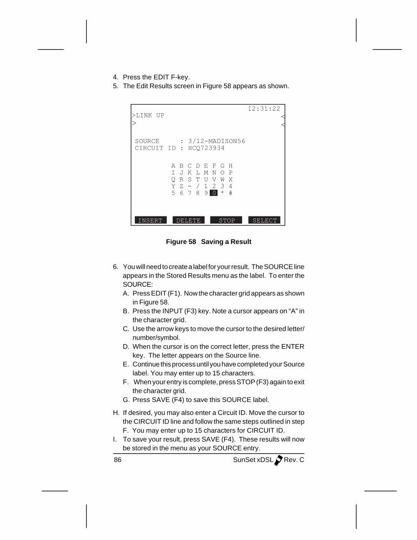
86 SunSet xDSL Rev. C
4. Press the EDIT F-key.5. The Edit Results screen in Figure 58 appears as shown.
12:31:22>LINK UP>
<<
SELECTINSERT DELETE STOP
SOURCE : 3/12-MADISON56CIRCUIT ID : HCQ723934
A B C D E F G HI J K L M N O PQ R S T U V W XY Z - / 1 2 3 45 6 7 8 9 0 * #
Figure 58 Saving a Result
6. You will need to create a label for your result. The SOURCE lineappears in the Stored Results menu as the label. To enter theSOURCE:A. Press EDIT (F1). Now the character grid appears as shown
in Figure 58.B. Press the INPUT (F3) key. Note a cursor appears on “A” in
the character grid.C. Use the arrow keys to move the cursor to the desired letter/
number/symbol.D. When the cursor is on the correct letter, press the ENTER
key. The letter appears on the Source line.E. Continue this process until you have completed your Source
label. You may enter up to 15 characters.F. When your entry is complete, press STOP (F3) again to exit
the character grid.G. Press SAVE (F4) to save this SOURCE label.
H. If desired, you may also enter a Circuit ID. Move the cursor tothe CIRCUIT ID line and follow the same steps outlined in stepF. You may enter up to 15 characters for CIRCUIT ID.
I. To save your result, press SAVE (F4). These results will nowbe stored in the menu as your SOURCE entry.

87Ch.7 Storing & Printing Results
1.1 Viewing Stored Results
Refer to the following procedure to view your stored results ata later time:
1. Press the STORE F-key found in a results screen.2. The STORED RESULTS screen appears in figure 52.3. Use the down arrow key to move the cursor to the result you
wish to view. If more than 10 results are stored, you may needto press the PAGE-DN (F2) key to find the result.
4. When the cursor has highlighted the correct result, press theVIEW (F2) key.
1.2 Locking Stored Results
You may lock your results to prevent them from being acciden-tally erased. When a result is locked, it cannot be edited or deleted(except by Erase NV Ram). To lock a result:
1. In the Stored Results menu, use the down arrow key to movethe cursor to the result you wish to lock. If more than 10 resultsare stored, you may need to press the PAGE-DN (F2) key to findthe result.
2. When the cursor is highlighting the correct result, press themore (F4) key; then press UN/LOCK (F2). The UN/LOCK keytoggles between locked and unlocked.
3. Note the right column now shows this result as locked.4. In order to unlock this result (to edit or delete it), press the UN/
LOCK F-key.
1.3 Clearing Stored Results
Refer to the following procedure to clear a stored result:
1. In the Stored Results menu, use the down arrow key to movethe cursor to the correct result.
2. Make sure the right column shows this result to be unlocked. Ifnot, you will need to press MORE (F4), then UN/LOCK (F2). Aresult cannot be deleted while locked.
3. When the cursor is highlighting the correct result, press theCLEAR (F3) key.
4. The result should now deleted and this space free to storeanother result.

88 SunSet xDSL Rev. C
1.4 Storing/ Recalling Results
To store and access results, you must be in a measurementscreen:
• For ADSL, this can be the Link Turn-up Results, General Status,Link Measurements, Bits per tone, and Alarm Status screens.
• For DMM, this is any of the DMM result screens (e.g. DCVscreen).
• For TDR, you must have started the TDR measurement.• For LINE, you must have started the LINE measurement (i.e.
you must be in the COIL DETECTION results screen).

89Ch.7 Storing & Printing Results
2.0 Printing Results
You may print the results in two ways:
• Printing Results: If you have stored results, as described inSection 1, you may print out the stored information.
• Printing individual screens: Pressing the orange Shift-functionPRINT key prints the single screen.
2.1 Configuring the Serial Port
In order to print correctly, the SunSet xDSLs serial port mustbe configured to match the destination printer/PC. To configurethe serial port:
1. Press the MENU key.2. Access OTHER SETUP > SERIAL PORT CONFG. Press
ENTER.3. Refer to Figure 59 and the following description of each setting.
12:23:38SERIAL PORT CONFIGURATION
BAUD RATE : 19200PARITY_BIT : NOSTOP_BIT : 1_BITDATA SIZE : 8_BITCR/LF INSRT : CRPRINT MODE : TEXTPRINT FORMAT: PRINTER
1200 1920096002400
Figure 59 Serial Port Configuration
BAUD RATEOptions: 1200 (F1), 2400 (F2), 9600 (F3), 19200 (F4)
Press the F-key that corresponds to your desired baud ratesetting. Make sure this setting matches that of the destinationprinter.

90 SunSet xDSL Rev. C
PARITY BITOptions: NO (F1), ODD (F2), EVEN (F3)
Parity is a method of checking the accuracy of transmitted orstored data. An extra bit, known as a parity bit, is added to thedata as an accuracy check. Make sure this setting matches thatof the destination printer.
• In Odd Parity (F2), the total number of ones (including the addedparity bit) is odd.
• In Even Parity (F3), the total number of ones (including theadded parity bit) is even.
• None (F1) signifies no parity checking.
STOP BITOptions: 1-BIT (F1), 2-BIT (F2)
In asynchronous transmission, the stop bit is the last trans-mitted character which permits the receiver to come into an idlecondition before accepting another character. Make sure this set-ting matches that of the destination printer.
DATA SIZEOptions: 5_BIT (F1), 6_BIT (F2), 7_BIT (F3), 8_BIT (F4)
Data Size specifies the number of bits per character. Makesure this setting matches that of the destination printer.
• Press (F1) to select 5 bits per character.• Press (F2) to select 6 bits per character.• Press (F3) to select 7 bits per character.• Press (F4) to select 8 bits per character.
CR/LF INSRTOptions: CR (F1), CR+LF (F2)
• Press CR (F1) to select carriage return.• Press CR+LF (F2) to select carriage return and line feed. This
mode inserts an extra line space after every line.
PRINT MODEOptions: TEXT (F1), GRAPHIC (F2)
Text: This mode prints a text-only format. If you are in text mode,you can only print from Alcatel ATU-R or ATU-C’s Stored Resultsscreen; the Print key is disabled. From the Stored Results menu,

91Ch.7 Storing & Printing Results
the text mode prints the Link Turn-up results and General Statusinformation. You cannot print any physical layer measurements (LINE,DMM, TDR). You should use text mode when your printer does notsupport graphics.
Graphic: This mode allows you to print both physical and ATU-Rresults. Graphic mode allows printing any single screen displayusing the PRINT Shift-function key. In ATU-R, graphic mode print-outs include: Link Turn-up Results, General Status, Link Measure-ments, and Alarm Status. Not all printers support graphics.Sunrise Telecom guarantees graphical printing only with the SS118printer provided by Sunrise Telecom.
PRINT FORMATOptions: PRINTER (F1), VT100 (F2)
Printer: Supports Sunset printers
VT100: Suppor ts terminal programs, such as WindowsHyperTerminal .
2.2 Printing from the SunSet xDSL
Follow these steps to print from the SunSet xDSL.
1. Verify that the SunSet xDSLs serial port is configured correctlyfor your printer.
2. Press the MENU key, then access OTHER SETUP > SERIALPORT CONFIG. Refer to Section 2.1 for more details on eachsetting.
3. Connect the SunSet xDSL to the printer. Plug the printer cablein the RJ-11 serial port located at the top of the set. SunriseTelecom provides three different printer cables:
• SS144: RJ-11 to DB-9• SS144A: RJ-11 to DB-25• SS144B: RJ-11 to RJ-11
You may print out the results in two ways:

92 SunSet xDSL Rev. C
Printing Single Screen displayTo print a single screen, simply press the PRINT key on the
keypad. This prints a bit-map graphic of the screen; the printoutlooks identical to the screen display. Since the PRINT key printsas a bit-map, it functions only when you have selected graphicprint mode in Serial Port Config and your printer supports graphic.
Printing Stored ResultsWhen you have stored results, you may print a full results
report. From a measurement screen, press the STORE F-key,then use the down arrow key to move the cursor to the desiredresult.
• You may see a combination of 4 different print F-key options.Press the more (F4) key to scroll through the various F-keychoices.
PRINT: Prints the stored result. This record consists of only onepage of results. An example is DMM; the PRINT F-key prints onemeasurement, like ACV.
PRN-ALL: Prints multiple pages of information associated with thisrecord. For example, in ATU-R testing, PRN-ALL prints all the ex-pected pages of ATU-R results.
PRN-TBL: Prints the results in a tabular format. This is applicableonly for Insertion Loss, Background Noise, and ADSL Bits perTone measurements.
PRN-GPH: Prints the results in a graphical format. This is appli-cable only for Insertion Loss, Background Noise, and ADSL Bitsper Tone measurements.
• When printing ATU-R stored results, text mode prints out boththe Link Turn-up Results and General Status information, alongwith the Source label and Circuit ID.
• When printing ATU-R stored results, the graphic mode printout:Link Turn-up, General Status, Alarm Status, and Link Measure-ments.

93Ch.7 Storing & Printing Results
2.3 Printing to a TAN printer
Refer to the following procedure if you are printing to a TANprinter:
1. Verify that the SunSet xDSLs serial port is configured correctlyfor your printer.A. Press the MENU key, access Other Setup > Serial Port
Config.B. Configure the setup items as follows:
BAUD RATE: 1200PARITY_BIT: NOSTOP_BIT: 1_BITDATA SIZE: 8_BITPRINT MODE:TEXTCR/LF INSRT: CR
2. Use the SS144B, RJ-11 to RJ-11, printer cable. Plug one endinto the TAN printer. The printer’s red light should now turngreen. If it does not, try the other end of the cable. Connect theother end of the cable into the SunSet xDSLs serial port- locatedon the top panel of the unit.
3. Since your Print Mode is set for text, you may print only thestored ATU-R results. Refer to Section 1 for details on storingresults. To print results:A. From either the Link Turn-up results or General Status
screens, press the STORE F-key.B. Cursor down to your desired result.C. Press more (F4), then PRN-ALL (F1)D. Both the Link Turn-up Results and General Status screens
will print.

94 SunSet xDSL Rev. C
2.4 Printing to a PC
In addition to printing to a serial port printer, you may alsosend your data to a PC configured for VT100 terminal emulation(i.e. Hyperterminal).
1. Verify that your serial port is configured properly for both thecomputer and the SunSet xDSL.
2. Connect the SunSet xDSL to the PC. You must use a null modemadapter for this application.
3. The following data can be printed to your computer:
• Text Mode: ADSL Modem Status and Link Turn-up Results.• Graphic Mode: print table for Bits per Tone, Insertion Loss, and
Background Noise.
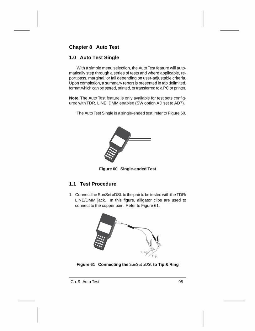
Ch. 9 Auto Test 95
Chapter 8 Auto Test
1.0 Auto Test Single
With a simple menu selection, the Auto Test feature will auto-matically step through a series of tests and where applicable, re-port pass, marginal, or fail depending on user-adjustable criteria.Upon completion, a summary report is presented in tab delimited,format which can be stored, printed, or transferred to a PC or printer.
Note : The Auto Test feature is only available for test sets config-ured with TDR, LINE, DMM enabled (SW option AD set to AD7).
The Auto Test Single is a single-ended test, refer to Figure 60.
Figure 60 Single-ended Test
1.1 Test Procedure
1. Connect the SunSet xDSL to the pair to be tested with the TDR/LINE/DMM jack. In this figure, alligator clips are used toconnect to the copper pair. Refer to Figure 61.
Tip
Ring
Figure 61 Connecting the SunSet xDSL to Tip & Ring

96 SunSet xDSL Rev. C
2. Press the MENU key, access AUTO TEST SINGLE and pressthe ENTER key. A Notice page will be displayed. Refer toFigure 62.
14:09:29
NOTE: Single-ended AUTO Testwill take about 6 minutes.You may ESCAPE at any time,but results will be lost.
AUTO TEST SINGLE
Press ENTER to begin
Figure 62 Auto Test Single, Notice
3. Pressing the ENTER key will start the test. During the test thefollowing message will be displayed “>AUTO TEST INPROGRESS”.
Notes
• Pressing the ESC key while the test is running will stop the test,and all results will be lost.
• A message will appear if Background Calibration has not beendone. You must enter the CALIBRATION Menu before procedingwith the AUTO TEST.
After AUTO TEST COMPLETED is displayed the user has 4 majorpages of data, they consist of:
• Screen 1: Voltage and Resistance readings• Screen 2: Background Noise PSD readings. This page contains
a summary page, graph page and a table page.• Screen 2: TDR results. This page contains a summary page
and a graph page.• Screen 4: Capacitance, Load Coil, G, F, E filter and Impulse
Noise readings.

Ch. 9 Auto Test 97
14:09:29>AUTO TEST COMPLETED
AUTO TEST Single Ended
DCV T-R : DONE :0.000 VDCV T-G : DONE :0.000 VDCV R-G : DONE :0.000 VACV T-R : PASS :0.001 VACV T-G : PASS :0.001 VACV R-G : PASS :0.001 VOHM T-R : PASS :>5 MOOHM T-G : PASS :>5 MOOHM R-G : PASS :>5 MO
PAGE UP PAGE DN STORE
Figure 63 Auto Test Completed, Results Page (Screen 1)
The following items appear in the Auto Test Completed, ResultsPage (Screen 1):
DCV T-R: DC Voltage Tip-to-Ring.
DCV T-G: DC Voltage Tip-to-Ground.
DCV R-G: DC Voltage Ring-to-Ground.
• For DCV readings there is no pass/fail threshold. Results aredisplayed only.
ACV T-R: AC Voltage Tip-to-Ring.
ACV T-G: AC Voltage Tip-to-Ground.
ACV R-G: AC Voltage Ring-to-Ground.
• For ACV readings, the following items apply:Pass: T-G or R-G < 10 VACMarginal: T-G or R-G ≥ 10 VAC, but ≤ 15 VAC.Fail: T-G or R-G > 15 VAC.
Notes:
• There is no pass/fail threshold applied to T-R measurement.• ACV thresholds are user definable.

98 SunSet xDSL Rev. C
OHM T-R: Resistance in ohms, Tip-to-Ring.
OHM T-G: Resistance in ohms, Tip-to-Ground.
OHM R-G: Resistance in ohms, Ring-to-Ground.
• For OHM readings the following items apply:Pass: T-R, T-G or R-G > 5 MΩMarginal: T-R, T-G or R-G > 3 kΩ but ≤ 5 MΩ.Fail: T-R, T-G or R-G < 3 kΩ.
Note : The above thresholds are defaults, this is a user definableparameter.
The following F-keys are displayed.
PAGE UP (F1), PAGE DN (F2): Allows access to the 4 majorpages of test results.
STORE (F3): Allows the user to store/print the test results. Whenan AUTO TEST result is stored the following table shows what canbe printed.
Screens Printer VT100 (PC) Auto Test Results X X TDR Graph X TDR Tabular Results X Background Noise Graph X Background Noise Tabular Results X
Table 2 Printer/VT100
Please see Chapter 7, Printing & Storing Results for moredetails.

Ch. 9 Auto Test 99
After pressing the PAGE DN F-key once the second screen,Background Noise PSD, Summary Page is displayed (Screen 2)
14:09:29>AUTO TEST COMPLETED
AUTO TEST Single Ended
BG NSE PSD :DONE :N/A
PAGE UP PAGE DN STORE GRAPH
Figure 64 Background Noise PSD, Summary Page
One additional F-key is added:
GRAPH (F4): This key allows access to the BACKGROUNDNOISE Graph. This is shown in the next figure, Background Noise,dBm/Hz Graph.
14:09:29Template:NONE
BACKGROUND NOISE
-110--112--113--115--116--118--119-
[4 ] [1600]X(kHz) :4.3 8.6 12.9Y(dBm/Hz):-120.0 -120.0 -120.0
GAINdBmTABLEMASKZOOM_IN
Figure 65 Background Noise, dBm/Hz Graph

100 SunSet xDSL Rev. C
The F-Keys in this screen are used as follows:
ZOOM_IN/ZOOM_OT (F1): The ZOOM key sets the display scalefor the screen. Press ZOOM-OUT to display the full 1.6 MHzbandwidth on the screen. The resolution is 3 tones/pixel with thehighest noise value of the three tones plotted on the screen.
After the ZOOM_IN key has been pressed another set of F-keys are displayed. They are:
PG_LFT (F1), PG_RGT (F2): These keys allow the user to changethe distance range shown in the Auto Test Single Ended, Graphfigures. The change in scale is shown in the bracketed numbersat the bottom of the graph.
Note : The Left and Right cursor keys on the keypad are now ac-tive. The user may move the cursor to a point on the graph andthe figures for X(kHz) and Y(dB or dBm) are displayed.
more (F4): Pressing this key returns to the previous screen.
MASK/CURSOR (F2): MASK places various templates of noisemasks on the screen to help you determine the interferer type.The interferer types are shown in the following Table.

Ch. 9 Auto Test 101
Interferer Type Description 24-DSL NEXT 24 IDSL services in the same binder group 10-HDSL NEXT 10 HDSL services in the same binder group 4-T1 ADJ NEXT 4 T1 services in an adjacent binder group 24-T1 ADJ NEXT 24 T1 services in an adjacent binder group 10-ADSL DN NEXT
10 ADSL downstream services in the same binder group
10-ADSL UP NEXT
10 ADSL upstream services in the same binder group
T1.601 NEXT ANSI T1.601 Basic Rate ISDN in the same binder pair
10-DSL NEXT 10 IDSL services in the same binder group 10-ADSL NEXT 10 ADSL services in the same binder group 10-T1 ADJ NEXT 10 T1 services in an adjacent binder group INT AMI 2M International 2.048 Mbps AMI signal (E1) ETSI BRA ETSI Basic Rate ISDN service ETSI HDSL ETSI HDSL service ADSL XTALK, ANSI 7,13
ADSL cross-talk ANSI loops 7 & 13
ADSL XTALK CSA 4
ADSL cross-talk, CSA loop 4
ADSL XTALK CSA 6
ADSL cross-talk, CSA loop 6
ADSL XTALK CSA 7
ADSL cross-talk, CSA loop 7
DSL NEXT IDSL service in the same binder group HDSL NEXT HDSL service in the same binder group G.DMT EC ADSL UP NEXT
G.DMT Echo-cancellation ADSL upstream service in the same binder group
G.DMT FDM ADSL UP NEXT
G.DMT Frequency division multiplexing ADSL upstream service in the same binder group
HDSL2 DN NEXT HDSL2 downstream service in the same binder group
HDSL2 UP NEXT HDSL2 upstream service in the same binder group
T1 NEXT T1 service in the same binder group EC ADSL DN Echo-cancellation downstream ADSL G.DMT FDM ADSL DN NEXT
G.DMT Frequency division multiplexing ADSL downstream service in the same binder group
Table 3 Interferer Type

102 SunSet xDSL Rev. C
After pressing MASK, use the left and right arrow keys toscroll through the various template masks. The exact mask dis-played is shown on the 2nd line at Template. Press the CURSOR(F2) key to return to the previous screen.
TABLE (F3): Press the Table key to access a tabular form of thegraph. Refer to Figures 67 and 68.
dBm and dBm/Hz (F4): This key toggles the noise reading at thebottom of the screen. dBm is a pure power reading with a refer-ence to 1 milliwatt. The dBm/Hz measurement uses a referenceof a certain frequency resolution bandwidth (4.3125 kHz) for thereading.
Pressing the dBm (F4) key displays the next screen shown inFigure 66, Auto Test Single Ended, dBm Graph.
14:09:29Template:NONE
BACKGROUND NOISE
X(kHz) :4.3 8.6 12.9Y(dBm/Hz):-83.7 -83.7 -83.7
GAINTABLEMASKZOOM_IN dBm/Hz
-74--75--77--78--80--81--83-
[4 ] [1600]
Figure 66 Background Noise dBm Graph
Pressing the TABLE (F3) key displays the next screen shownin Figure 67, Background Noise, dBm Table.

Ch. 9 Auto Test 103
14:09:29
BACKGROUND NOISE
dBmPG_DN PG_UP GRAPH
kHz417304356698295108121
LEVEL -120 -120 -120 -120 -120 -120 -120 -120 -120 -120
kHz922354760738699112125
LEVEL -120 -120 -120 -120 -120 -120 -120 -120 -120 -120
kHz13263952657891104116129
LEVEL -120 -120 -120 -120 -120 -120 -120 -120 -120 -120
Figure 67 Background Noise, dBm/Hz Table
Pressing the dBm (F4) key displays the next screen shown inFigure 68, Auto Test Single Ended, dBm/Hz Table.
14:09:29
BACKGROUND NOISE
PG_DN PG_UP GRAPH
kHz417304356698295108121
LEVEL -84 -84 -84 -84 -84 -84 -84 -84 -84 -84
kHz922354760738699112125
kHz13263952657891104116129
dBm/Hz
LEVEL -84 -84 -84 -84 -84 -84 -84 -84 -84 -84
LEVEL -84 -84 -84 -84 -84 -84 -84 -84 -84 -84
Figure 68 Auto Test Single Ended, dBm Table
Pressing the ESC key once and the PAGE DN key once bringsyou to the third page of test data, TDR Results.

104 SunSet xDSL Rev. C
14:09:29>AUTO TEST COMPLETED
AUTO TEST Single Ended
TDR :NO FAULTS:0
PAGE UP PAGE DN STORE GRAPH
Figure 69 Auto Test Single Ended, TDR
The TDR summary page, Figure 69, will list the nearest faultto the SunSet xDSL and give its distance in feet or meters.
Pressing the Graph (F4) key displays a graph of the line asshown in Figure 70.
14:09:29
PAGE UP PAGE DN MARKER
TDR
[10 ]MARKER: 384.2 MARKER GAIN
[940 ][O: 0 ][H: 16 ][V: 1.00 ]
DISTANCE: 10.0 FEET
Figure 70 Auto Test Single Ended, TDR Graph

Ch. 9 Auto Test 105
Display Items on the Graph in Figure 70
[10 ] shows the distance at the left-most start of the screen.
[940 ] shows the distance at the right-most end of the screen.
MARKER/CURSOR: shows the distance between the Marker andthe Cursor. If the cursor is at the beginning of a bridge tap and themarker is at the open at the end, this value shows the length ofyour bridge tap.
O: shows the Offset value. Offset represents the vertical positionof the pulse on the screen. This can range from +64 (high onscreen) to -64 (low on screen).
H: shows the Zoom factor. Zoom refers to the scale of the screen.This can range from 1-512. 1 shows only a limited portion of thescreen in more detail. 512 shows the whole cable span.
V: shows the Gain value. Gain adjusts the strength of the pulse.This can range from 32 (strongest) to .125 (weakest).
For further information on the TDR phase of this test, pleasesee Chapter 4, TDR.
Pressing the ESC key once and pressing the PAGE DN (F3)key once bring you to the last major page of information. Refer toFigure 71
14:09:29>AUTO TEST COMPLETED
AUTO TEST Single Ended
CAP BALANCE:PASS :100 %CAP LENGTH :DONE :64 ftCOIL DETECT:PASS :0G Filter :PASS :-66 dBmF Filter :PASS :-74 dBmE Filter :PASS :-73 dBmIMP NSE HI :DONE :0IMP NSE MID:DONE :0IMP NSE LOW:DONE :0
PAGE DNPAGE UP STORE
Figure 71 Auto Test Completed, Results Page (Screen 4)

106 SunSet xDSL Rev. C
The following items appear in the Auto Test Completed , ResultsPage (Screen 4):
CAP BALANCE: Capacitive Balance
Capacitive Balance is a measurement of the cable balance bycomparing the capacitance tip-to-ground and ring-to-ground val-ues. The balance is expressed as a ratio of (tip-to-ground) and(ring to ground) capacitance values. Pass/Marginal/Fail criteriaare applied per the user-defined threshold. Using the default set-ting, the following is derived:
PASS: Balance ≥ 95%MARGINAL: 90% ≤ Balance < 95%FAIL: Balance < 90%
• These are user definable parameters.
CAP LENGTH: Loop Length based on capacitance Tip-Ring mea-surement.
• The correlation factor is a user definable parameter.• The feet or meter setting can be set in the SYSTEM
CONFIGURATION menu.
COIL DETECT: Load Coil detector count.
PASS: 0 coilsFAIL: 1 or more coils
G FILTER:
PASS: Result < -50 dBmMARGINAL: Result ≥ -50 dBm
• This is a user definable parameter. Default is as shown.
F FILTER:
PASS: < -56 dBmMARGINAL: ≥ -56 dBm
• This is a user definable parameter. Default is as shown.
E FILTER:
PASS: < -63 dBmMARGINAL: ≥ -63 dBm
• This is a user definable parameter. Default is as shown.
Ch. 9 Auto Test 107
IMP NSE: Impulse Noise
Default Settings
Threshold: 75 dBrnDelta: 4 dBMax Count: 999Dead Time: 125 mSTimer: 1 minute
• Settings are editable in the IMPULSE NOISE MAIN MENU.• To keep the AUTO TEST at a reasonable duration, the
Impulse noise test will be limited to 5 minutes or less. Thetimer may be set from 1 - 5 minutes. If the setting is greaterthan 5 minutes then the 1 minute setting will be used. Usersrequiring a longer test can run the test in manual mode.

108 SunSet xDSL Rev. C
2.0 Measurement Settings
In the previous section there were many references to “userdefinable parameters” to determine PASS/MARGINAL/FAIL thresh-olds where applicable. This menu item allows the user to definethose parameters within certain ranges.
Notes:
• Measurement settings apply to the AUTO TEST feature only.• TDR setup is under the Main Menu > TDR.• IMPULSE NOISE setup is under the Main Menu > LINE >
IMPULSE NOISE.
To access the Measurement Settings menu, press the MENUkey on the keypad > OTHER SETUP > MEASUREMENT SET-TINGS. There are two screens, refer to Figures 72 and 73.
14:09:29
MEASUREMENT SETTINGS
CAP Loop (ft): 83 nF/mileCAP Loop (m) : 52.4 nF/kmCAP BAL High : 95 %CAP BAL Low : 90 %ACV High : 15 VACV Low : 10 VOHM High : 5 MOOHM Low : 3 KOG Filter Pass: -50 dBmF Filter Pass: -56 dBm
morePAGE-UPPAGE-DN
Figure 72 Measurement Settings, Screen 1
Options: PAGE-DN (F1), PAGE-UP (F2), Scroll+ (more, F1),SCROLL- (more, F2), DEFAULT (more, F3).
PAGE-DN & PAGE-UP: Allows access to the next or previous page.
Scroll+ and SCROLL- : Allows changes to the selected setting.
Note : Scroll+ and SCROLL- only apply to CAP Loop (ft) and CAPLoop (m). These two F-keys change to +1 (F1) and -1 (F2) in allother settings.

Ch. 9 Auto Test 109
DEFAULT: Restores the factory defaults to all settings in the Mea-surement Settings menu item.
14:09:29
MEASUREMENT SETTINGS
E Filter Pass: -62 dBm
PAGE-UPPAGE-DN-1+1
Figure 73 Measurement Settings, Screen 2
The following items are displayed within Measurement Set-tings, Screens 1 and 2.
CAP Loop (ft): Capacitance Loop length correlation factor in feet.
Range: 37-129 nF/mileDefault: 83 nF/mile
CAP Loop (m): Capacitance Loop length correlation factor in km.
Range: 23-80 nF/kmDefault: 52.4 nF/km
CAP BAL High: Capacitive Balance High as a percentage.
Range: 95-99%Default: 95%
CAP BAL Low: Capacitive Balance Low as a percentage.
Range: 85-90%Default: 90%

110 SunSet xDSL Rev. C
ACV High: AC Voltage High for Tip-Ground, Ring-Ground
Range: 15-50VDefault: 15V
ACV Low: AC Voltage Low
Range: 1 to 10VDefault: 10V
OHM High: Resistance High in mega Ohms
Range: 1 to 5 MΩDefault: 5 MΩ
OHM Low: Resistance Low in kilo Ohms
Range: 1 to 3 kΩDefault: 3 kΩ
G Filter Pass:
Range: -74 to +26 dBmDefault: -50 dBm
F Filter Pass:
Range: -74 to +26 dBmDefault: -56 dBm
E Filter Pass:
Range: -74 to +26 dBmDefault: -62 dBm

Ch.9 Customer Information 111
Chapter 9 Customer Information
1.0 Customer Service
General Sunrise Telecom Customer Service is available from7:30 AM to 5:30 PM Pacific Standard Time (California, U.S.A.).
Customer Service performs the following functions:
• Answers customer questions over the phone on such topics asproduct operation and repair.
• Facilitates prompt repair of malfunctioning SunSets.• Provides information about product upgrades.
A Return Merchandise Authorization (RMA) Number is requiredbefore any product may be shipped to Sunrise Telecom for repair.Out-of-warranty repairs require both an RMA and a Purchase Or-der before the unit is returned. All repairs are warranted for 90days.
Please contact Customer Service if you need additional as-sistance:
Customer ServiceSunrise Telecom Incorporated22 Great Oaks Blvd.San Jose, CA 95119U.S.A.Tel: 1 408 363 8000 or 1-800-701-5208Fax: 1 408 363 8313Internet: http://www.sunrisetelecom.comEmail: [email protected]
xDSL Support Hotline
In addition to general customer service, a 24-hour xDSL sup-port line is available for dedicated xDSL technical support. Ourknowledgeable xDSL support staff is ready to help you with anyquestions you might have regarding xDSL testing.
Call: 1-888-922-XDSL

112 SunSet xDSL Rev. C

Ch.9 Customer Information 113
2.0 Express Limited Warranty
A. Hardware Coverage. COMPANY warrants hardware productsagainst defects in materials and workmanship. During thewarranty period COMPANY will, at its sole option, either (i)refund of CUSTOMER’S purchase price without interest, (ii)repair said products, or (iii) replace hardware products whichprove to be defective; provided, however, that such productswhich COMPANY elects to replace must be returned to COM-PANY by CUSTOMER, along with acceptable evidence ofpurchase, within twenty (20) days of request by COMPANY,freight prepaid.
B. Software and Firmware Coverage. COMPANY warrants soft-ware media and firmware materials against defects in materialsand workmanship. During the warranty period COMPANY will,at its sole option, either (i) refund of CUSTOMER’S purchaseprice without interest, (ii) repair said products, or (iii) replacesoftware or firmware products which prove to be defective;provided, however, that such products which COMPANY electsto replace must be returned to COMPANY by CUSTOMER,along with acceptable evidence of purchase, within twenty (20)days of request by COMPANY, freight prepaid. In addition,during the warranty period, COMPANY will provide, withoutcharge to CUSTOMER, all fixes and patches to the originalproduct specifications sold which COMPANY issues during thewarranty period. COMPANY does not warrant or represent thatall software defects will be corrected. In any case whereCOMPANY has licensed a software product “AS-IS,”COMPANY’S obligation will be limited to replacing an inaccu-rate copy of the original material. This warranty does not coverupgrade or enhancements to product software and firmware.
C. Period. The warranty period for Hardware, Software andFirmware will be One (1) Year from date of shipment toCUSTOMER. The COMPANY may also sell warranty exten-sions or provide a warranty term of three years with the originalsale, which provide a longer coverage period for the test setchassis, software and firmware, in which case the terms of theexpress limited warranty will apply to said specified warrantyterm.
114 SunSet xDSL Rev. C
D. Only for CUSTOMER. COMPANY makes this warranty only forthe benefit of CUSTOMER and not for the benefit of anysubsequent purchaser or licensee of any merchandise.
E. LIMITATION ON WARRANTY. THIS CONSTITUTES THESOLE AND EXCLUSIVE WARRANTY MADE BY COMPANYWITH RESPECT TO HARDWARE, SOFTWARE AND FIRM-WARE. THERE ARE NO OTHER WARRANTIES, EXPRESSOR IMPLIED. COMPANY SPECIFICALLY DISCLAIMS THEIMPLIED WARRANTIES OF MERCHANTABILITY AND FIT-NESS FOR A PARTICULAR PURPOSE. COMPANY’S LI-ABILITY UNDER THIS AGREEMENT WITH RESPECT TO APRODUCT, INCLUDING COMPANY’S LIABILITY FOR FAIL-URE AFTER REPEATED EFFORTS TO INSTALL EQUIP-MENT IN GOOD WORKING ORDER OR TO REPAIR ORREPLACE EQUIPMENT, SHALL IN NO EVENT EXCEED THEPURCHASE PRICE OR LICENSE FEE FOR THAT PRODUCT,NOR SHALL COMPANY IN ANY EVENT BE LIABLE FOR ANYINCIDENTAL, CONSEQUENTIAL, INDIRECT, OR SPECIALDAMAGES OF ANY KIND OR NATURE WHATSOEVER,ARISING FROM OR RELATED TO THE SALE OF THEMERCHANDISE HEREUNDER, INCLUDING BUT NOT LIM-ITED TO DAMAGES ARISING FROM OR RELATED TO LOSSOF BUSINESS, LOSS OF PROFIT, LOSS OF GOODWILL,INJURY TO REPUTATION, OVERHEAD, DOWNTIME, RE-PAIR OR REPLACEMENT, OR CHARGE-BACKS OR OTHERDEBITS FROM CUSTOMER OR ANY CUSTOMER OF CUS-TOMER.
G. No Guaranty, Nonapplication of Warranty. COMPANY does notguaranty or warrant that the operation of hardware, software, orfirmware will be uninterrupted or error-free. Further, the warrantyshall not apply to defects resulting from:(1) Improper or inadequate maintenance by CUSTOMER;(2) CUSTOMER-supplied software or interfacing;(3) Unauthorized modification or misuse;(4) Operation outside of the environmental specifications for the
product;(5) Improper site preparation or maintenance; or(6) Improper installation by CUSTOMER.

Index 115
IndexSymbols15VDC port; 23800 tech-support number; 111
AACV
High; 110Low; 110R-G; 97T-G; 97T-R; 97
Auto key; 15
BBattery
Charger; 9LED; 20Replacing; 24
Bridge Tap; 38
CCAP
BAL High; 109BAL Low; 109Balance; 106Length; 106Loop (ft); 109Loop (m); 109
Charger; 23Circuit ID; 86Coil Detect; 106Conexant RS8973 SDSL chipset; 8Contrast Key; 15Copper CrossConnect™ CX100; 79Copper Mountain Copper Edge; 8
DDCV
R-G; 97T-G; 97T-R; 97
Digital Multimeter; 43DMM; 43

SunSet xDSL Rev. C116
EE Filter; 106
Pass; 110ERR INJ Key; 15ESCAPE key; 13, 15, 16
FF Filter; 106
Pass; 110Figure
01 DSL SPAN; 502 SunSet xDSL Front View; 1103 SunSet xDSL Keypad; 1204 Main Menu Flowchart; 1405 SunSet xDSL LED Panel; 1706 Right Side Panel; 2107 SunSet xDSL Top Panel; 2308 Replacing the Battery Pack; 2409 TDR Setup Screen; 2710 Auto Search; 3011 Result Zoomed Out; 3112 Zooming in Once; 3213 Zooming in Twice; 3314 Auto Search Lower Screen Items; 3415 Bridge Tap at 1589 ft; 3516 Page-right, Viewing from 1544 to 4834; 3617 Page-right, Viewing from 4856 to 8069; 3618 Zoom out, Viewing from 4856 to 11281 ft; 3719 Typical Load Coil/Open; 3820 Typical Bridge Tap; 3921 Typical Short; 4022 Connecting to the Cable Pair; 4123 Fault Found; 4224 Digital Multimeter Menu Screen; 4325 Capacitance Screen; 4426 Resistance Screen; 4527 AC Voltage Screen; 4628 DC Voltage Screen; 4729 Connecting with RJ-45 to Alligator Clip; 4830 Single-ended test; 4931 Paired Tests; 5032 Connecting the SunSet xDSL to Tip & Ring; 5133 Background Noise Setup Screen; 5234 PSD Background Noise Results; 5435 Background Noise-TERM Mode; 5536 Background Noise- BRIDGE Mode; 58

Index 117
37 Level Meter; 6038 Frequency Generator; 6139 Connecting the SunSet xDSL to the Cable Pair; 6240 Coil Detection; 6341 Connecting the SunSet xDSL to the Cable Pair; 6442 Impulse Noise Setup; 6543 Impulse Noise Results; 6744 Connecting the SunSet xDSL to Tip & Ring; 6945 ADSL PSD Insertion Loss Result; 6946 Insertion Loss-Table format; 7047 Single Frequency Insertion Loss; 7248 Signal-to-Noise Result for ADSL DMT PSD; 7349 Connecting the SunSet xDSL to the Circuit to; 7550 Loop Resistance Screen; 7651 Responder Mode; 7752 Connection from CX100 to SunSet xDSL; 7953 Remote Auto Test Screen; 8054 Remote Auto Test Completed Screen; 8155 Background Noise for Filters E, F and G; 8256 ADSL PSD Background Noise Measurement; 8357 Stored Results Menu; 8558 Saving a Result; 8659 Serial Port Configuration; 8960 Single-ended Test; 9561 Connecting the SunSet xDSL to Tip & Ring; 9562 Auto Test Single, Notice; 9663 Auto Test Completed, Results Page (Screen 1); 9764 Background Noise PSD, Summary Page; 9965 Background Noise, dBm/Hz Graph; 9966 Background Noise dBm Graph; 10267 Background Noise, dBm/Hz Table; 10368 Auto Test Single Ended, dBm Table; 10369 Auto Test Single Ended, TDR; 10470 Auto Test Single Ended, TDR Graph; 10471 Auto Test Completed, Results Page (Screen 4); 10572 Measurement Settings, Screen 1; 10873 Measurement Settings, Screen 2; 109
Frequency Generator; 61
GG Filter; 106
Pass; 110
HHistory Key; 15

SunSet xDSL Rev. C118
IIMP NSE; 107Inductor; 62Insertion Loss Test
Single Frequency; 72
KKeys
0-9; 16A-F; 16AUTO; 15Contrast; 15Cursor; 15Enter; 15ERR INJ; 15ESCAPE; 13F1-F4; 13History; 15Light; 15Menu; 13Module; 13Print; 16Status; 15
LLEDs; 17
ALARM; 19BATTERY; 20BIT ERR; 20BPV/CODE; 19DMM; 18Frame; 19HOLD; 19LINE; 18LP 1 SYNC; 18LP 2 SYNC; 19PAT SYNC; 20POWER; 20RESPOND; 20T1/E1 SIG; 18TDR; 18xDSL; 17xTU-C; 17xTU-R; 18
Load Coil; 62Load Coil/Open; 38

Index 119
Loop Resistance Test; 75Lucent TNT & Stinger; 8
MMASK; 100more; 13
NNokia Speedlink; 8
OOHM
High; 110Low; 110R-G; 98T-G; 98T-R; 98
Pparity; 90PRINT Key; 16Printing
Graphic Mode; 90, 91Text Mode; 90, 91to a PC; 94to TAN printer; 93
PRN-ALL; 92PRN-GPH; 92PRN-TBL; 92
RRemote Auto Testing
256 Tone Sweep; 81COTE; 80FETE; 80Results Exchange; 81
Removing Load Coils; 64Repair; 111Replacing the Battery Pack; 24RMA; 111RMA Number; 111

SunSet xDSL Rev. C120
SSerial Port
Configuration; 89Signal to Noise Test; 73Source; 86Stop Bit; 90Support Hotline; 111System Clock; 10
TTable
01 Interferer Type; 5602 Printer/VT100; 9803 Interferer Type; 101
TAN printer; 93TDR; 27
Sample Waveforms; 38TDR Hints; 37Time Domain Reflectometer; 27Turnstone Inc.; 79Typical Short; 40
VVelocity of Propagation; 29Volume Key; 15VP; 28VT100 terminal
Printing to; 94
WWarranty; 113

Index 121