Embed Size (px)
Citation preview
ATouch User Guide
1
Surface Acoustic Wave Touchscreen
Table of Contents Chapter 1 Introduction ………………………………. 3
1.1 Touchscreen Sensor ………………………………… 3
1.1.1 Standard Sensor …………………………................. 3
1.1.2 Anti-Vandalism Sensor …………………….............. 4
1.1.3 Protected SAW Sensor ……………..………………. 4
1.2 Touchscreen Controller …………………………….. 4
1.3 Software Drivers …………………………………..… 5
1.4 Agency Approvals …………………………………… 5
1.5 Warranty …………………………………………… 5
Chapter 2 Touchscreen Installation …………………. 6 2.1 CRT Monitor Installation ………………………..… 6
2.2 LCD Monitor Installation …...………………..…… 8
Chapter 3 Software Driver Installation …….………. 11 3.1 RS-232 Software Driver Installation for Windows 11
3.1.1 Installing the Touch Driver ……………………..…. 11
3.1.2 Uninstalling the Touch Driver …….…………..…… 14
3.1.3 Calibration ………………………………………….. 15
3.1.4 Control Center ………………………………….….. 17
3.2 USB Software Driver Installation for Windows ..… 25
3.3 Linux Driver…….…………………………………… 31

ATouch User Guide
2
Chapter 4 Troubleshooting ……………………….…. 32
Chapter 5 Contact ……………………………………. 34
ATouch User Guide
3
Chapter 1 Introduction ATouch Technologies Co., Ltd. Surface Acoustic Wave Touchscreen is a
pure glass surface Touch Screen in different types and dimensions.
CRT : Spherical CRT : 15”/17”/19”/21”
Flat CRT : 17”/19”/21”
LCD : 6.4”/10.4”/12.1”/14.1”/15”/17”/18.1”/19”/20.1”/23.1”
Surface Acoustic Wave Touchscreen features :
-Superior image clarity with high light transmission
-Sensitive and fast response
-Durability, deep scratch resistance and abrasion
-Highest resolution
-Active by finger, gloved hand, leather or soft stylus
-More then 50 million touches for a single point
-Dirt and splash sealed capability
-Custom size for OEM available
1.1 Touchscreen Sensor ATouch SAW Touchscreen sensor with 3 different types for customers’
option :
- Standard Sensor
- Anti-vandalism Sensor
- Protected SAW Sensor
ATouch User Guide
4
1.1.1 Standard Sensor It is 3mm-thickness standard glass.
1.1.2 Anti-Vandalism Sensor It is 6mm-thickness heat strengthened glass, meets UL1950
specification.
1.1.3 Protected SAW Sensor It is 6mm thickness heat strengthened glass, meets UL1950
specification with the ABS plastic frame covered around touch sensor.
It is dirt / dust / splash / water resistant.
1.2 Touchscreen Controller The ATouch SAW controller offers the drive signal for the
touchscreen, converts the received analog acoustic wave signals into
digital coordinates of the touch point, and sends the coordinates to the
computer.
The controller detects touch points by the comparison between
received average amplitude of vibration of the acoustic wave signals and
reference average waveform acquired when the touchscreen is in an
untouched condition. The controller is capable of detecting the stay time
of dirt, dust, water drops, scratches and other contaminants on the
screen and then ignores them. If the contamination is removed, the
controller relearns the original reference average waveform.
The re-calibration is not necessary unless the position of the video
image changes.
ATouch User Guide
5
Resolution of the ATouch SAW touch system based on the controller is
4096 x 4096.
1.3 Software Drivers Drivers support operating system are as follow :
Windows : 95/98/Me/2000/XP/NT
Linux : Red Hat 9.0, Mandrake 9.1
1.4 Agency Approvals FCC
CE
1.5 Warranty ATouch SAW Touchscreen products are the following warranty.
Touch sensor : 10 years
Controller (RS-232 / USB) : 5 years
ATouch User Guide
6
Chapter 2 Touchscreen Installation
2.1 CRT Monitor Installation CRT monitor installation process as following steps :
1. Incoming inspection
CRT monitor : please check if the monitor works well.
Touchscreen : please unpack the touchscreen, connect your
touchscreen with the controller on your PC and test if the
touchscreen works well.
After testing the monitor and touchscreen, you can start to install
touchscreen into your monitor by the following steps.
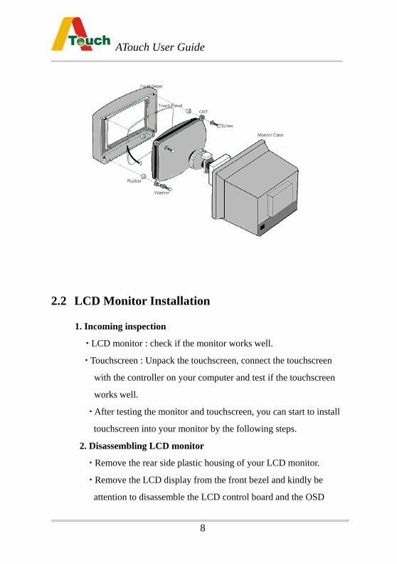
2. Disassembling CRT monitor
Remove the back side plastic housing of your CRT monitor.
Discharge the CRT tube from the front bezel (usually there are 4
screws on the 4 corners need to be released).
Check if the electronic board needs to be removed or not.
Verify the fit position on the CRT tube for the touchscreen.
After verifying the position, you can attach the touch sensor onto
the CRT. You can use the double side high tack adhesive tape (as
3M) to attach the touch sensor onto the CRT display
After this process, check the space between the touch
sensor and the front bezel. If the space is not enough, you may
need to add rubber spacers between the touch sensor and the front
bezel ( the 4 corners on which the CRT and the front bezel is
ATouch User Guide
7
screwed ).
Installing Touchscreen Controller
Connect all cables / connectors in right places and fix the
controller at the monitor chassis.
Power Supply
If you use internal power supply +5VDC, connect the power
cord (from touchscreen RS-232 controller) to the CRT monitor
electronic board +5VDC.
If the external power supply is used, the +5VDC will be
supplied from the keyboard through the RS-232 cable provided by
ATouch.
Fixing Cables
Cables should be fixed well and not movable.
After above processes, test if the touch monitor works normally.
3. Reassembling CRT Monitor
After the installation of the touchscreen, reassemble the CRT
monitor back side plastic housing and test if the function of the
touch monitor works well.
4. Sealing
Sealing should be even around the front bezel. The material is
special sponges from ATouch. The adhesive side of the sponge is
stuck on the front bezel, and the special plastic side on the touch
sensor.
Or use the material manufactured by VOLTEK.
(Suggest from VOLTEK : 2A/2E//4A/4E black flame retardant
material)
ATouch User Guide
8
2.2 LCD Monitor Installation
1. Incoming inspection
LCD monitor : check if the monitor works well.
Touchscreen : Unpack the touchscreen, connect the touchscreen
with the controller on your computer and test if the touchscreen
works well.
After testing the monitor and touchscreen, you can start to install
touchscreen into your monitor by the following steps.
2. Disassembling LCD monitor
Remove the rear side plastic housing of your LCD monitor.
Remove the LCD display from the front bezel and kindly be
attention to disassemble the LCD control board and the OSD
ATouch User Guide
9
board.
Verify the fit position on the LCD display for the touchscreen.
After verifying the position, attach the touchscreen sensor on the
LCD. Use the double side high tack adhesive tape (as 3M) to
attach touchscreen sensor on the LCD display.
After this process, check the space between the touchscreen sensor
and the front bezel if there is any gape ( You can use the special
sponge provided by ATouch to fulfill it).
Installing Touchscreen Controller
Connect all cables / connectors in the right places and fix the
controller at the right position on the monitor rear side metal or
plastic case.
Power supply
If you use internal power supply +5VDC, connect the power
cord (from touchscreen RS-232 controller ) to the LCD control
board +5VDC.
If the external power supply is used, the +5VDC will be
supplied from the keyboard through the RS-232 cable provided
by ATouch.
Fixing Cables
Cables should be fixed well and not movable. Please note that
cables do not get close to the inverter or the power supply.
After above processes, test if the touch monitor works well.
3. Reassembling LCD Monitor
After the processes mentioned above, reassemble the rear side
ATouch User Guide
10
plastic housing of the LCD monitor.
Seal the monitor if you need to seal it before you reassemble the
front bezel of the LCD monitor.
Test if the touch monitor function works well.
4. Sealing
Sealing should be even around the front bezel. The material is
the special sponges from ATouch. The adhesive side of the sponge
is stuck on the front bezel, and the special plastic side on the touch
sensor.
Or use the material manufactured by VOLTEK
(Suggest from VOLTEK : 2A/2E//4A/4E black flame retardant
material).
ATouch User Guide
Chapter 3 Software Driver Installation
3.1 RS-232 Software Driver Installation for Windows The following installation is applied to
Windows 95/98/Me/2000/XP/NT
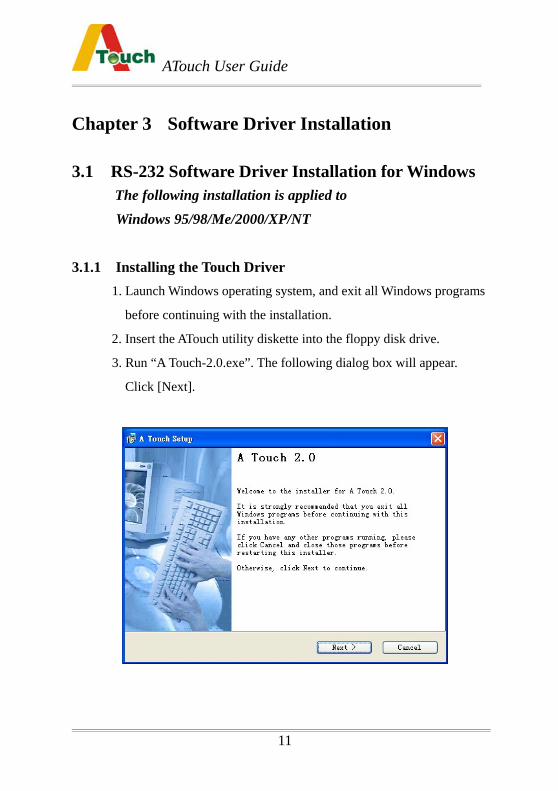
3.1.1 Installing the Touch Driver
1. Launch Windows operating system, and exit all Windows programs
before continuing with the installation.
2. Insert the ATouch utility diskette into the floppy disk drive.
3. Run “A Touch-2.0.exe”. The following dialog box will appear.
Click [Next].
11
ATouch User Guide
12
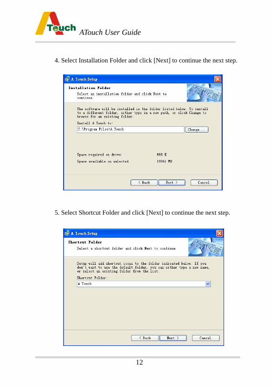
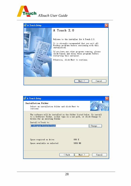
4. Select Installation Folder and click [Next] to continue the next step.
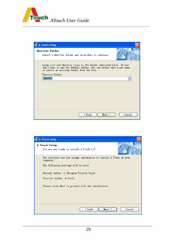
5. Select Shortcut Folder and click [Next] to continue the next step.
ATouch User Guide
13
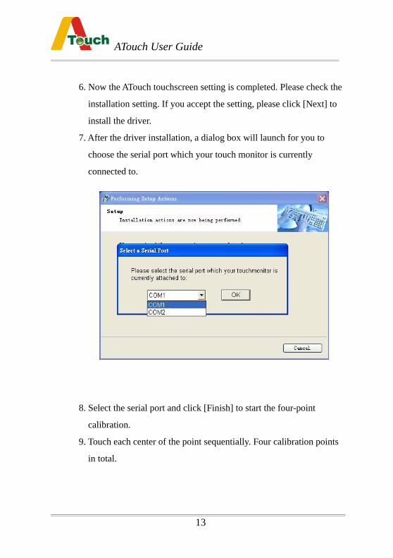
6. Now the ATouch touchscreen setting is completed. Please check the
installation setting. If you accept the setting, please click [Next] to
install the driver.
7. After the driver installation, a dialog box will launch for you to
choose the serial port which your touch monitor is currently
connected to.
8. Select the serial port and click [Finish] to start the four-point
calibration.
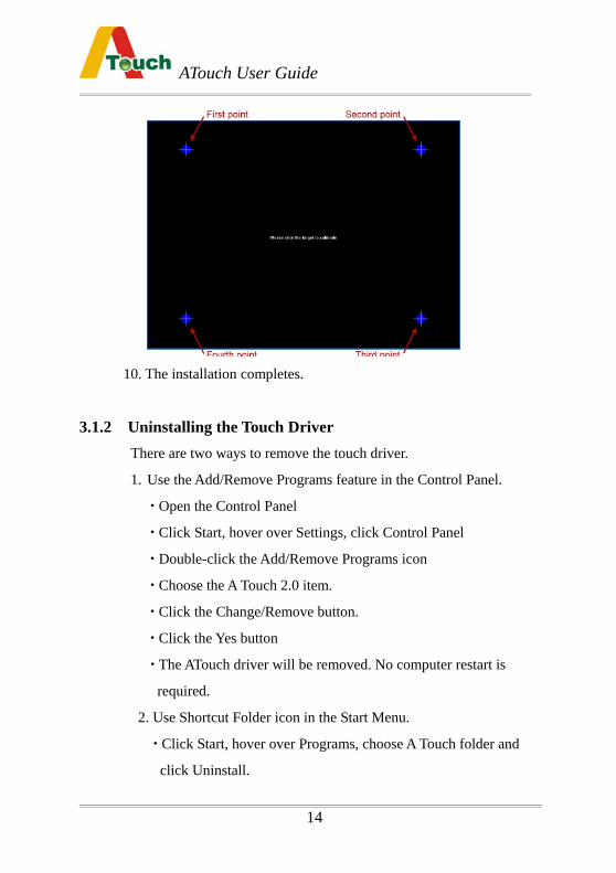
9. Touch each center of the point sequentially. Four calibration points
in total.
ATouch User Guide
14
10. The installation completes.
3.1.2 Uninstalling the Touch Driver There are two ways to remove the touch driver.
1. Use the Add/Remove Programs feature in the Control Panel.
Open the Control Panel
Click Start, hover over Settings, click Control Panel
Double-click the Add/Remove Programs icon
Choose the A Touch 2.0 item.
Click the Change/Remove button.
Click the Yes button
The ATouch driver will be removed. No computer restart is
required.
2. Use Shortcut Folder icon in the Start Menu.
Click Start, hover over Programs, choose A Touch folder and
click Uninstall.
ATouch User Guide
15
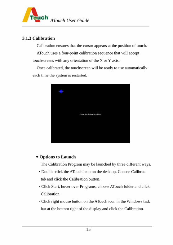
3.1.3 Calibration Calibration ensures that the cursor appears at the position of touch.
ATouch uses a four-point calibration sequence that will accept
touchscreens with any orientation of the X or Y axis.
Once calibrated, the touchscreen will be ready to use automatically
each time the system is restarted.
Options to Launch The Calibration Program may be launched by three different ways.
Double-click the ATouch icon on the desktop. Choose Calibrate
tab and click the Calibration button.
Click Start, hover over Programs, choose ATouch folder and click
Calibration.
Click right mouse button on the ATouch icon in the Windows task
bar at the bottom right of the display and click the Calibration.
ATouch User Guide
16
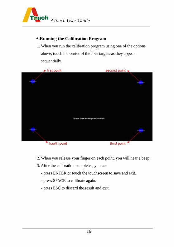
Running the Calibration Program 1. When you run the calibration program using one of the options
above, touch the center of the four targets as they appear
sequentially.
2. When you release your finger on each point, you will hear a beep.
3. After the calibration completes, you can
- press ENTER or touch the touchscreen to save and exit.
- press SPACE to calibrate again.
- press ESC to discard the result and exit.
ATouch User Guide
17
3.1.4 Control Center
The control Center application allows configuration of the driver to suit
the application programs, and present system and diagnostic
information to the user.
Each of the five tabs in the Control Center is described below.
1. Running the Control Center The Control Center may be launched by four different ways to
adjust the properties.
Double-click the ATouch icon on the desktop.
Click Start, hover over Programs, choose ATouch folder and click
Control Center.
Click the ATouch icon in the Windows task bar at the bottom right
of the display.
Click right mouse button on the ATouch icon in the Windows task
bar at the bottom right of the display and click Show Control
Center.
ATouch User Guide
18
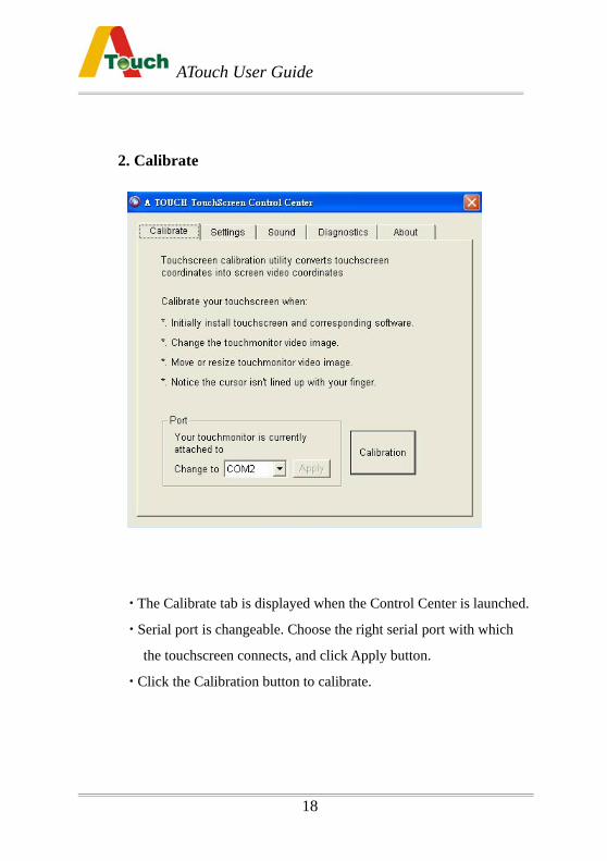
2. Calibrate
The Calibrate tab is displayed when the Control Center is launched.
Serial port is changeable. Choose the right serial port with which
the touchscreen connects, and click Apply button.
Click the Calibration button to calibrate.
ATouch User Guide
19
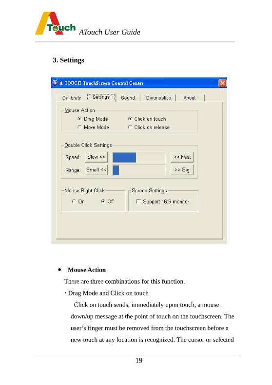
3. Settings
Mouse Action
There are three combinations for this function.
Drag Mode and Click on touch
Click on touch sends, immediately upon touch, a mouse
down/up message at the point of touch on the touchscreen. The
user’s finger must be removed from the touchscreen before a
new touch at any location is recognized. The cursor or selected
ATouch User Guide
20
objects can be dragged on the screen in this mode.
Move Mode and Click on touch
Click on touch sends, immediately upon touch, a mouse
down/up message at the point of touch on the touchscreen. The
user’s finger must be removed from the touchscreen before a
new touch at any location will be recognized. The cursor or
selected objects cannot be dragged on the screen in this mode.
Move Mode and Click on release
Click on release sends, at the time of release, a mouse down/up
message at the point that the screen was last touched. Dragging
across objects on the screen will not highlight or select them
unless untouch occurs when the touch is over the object.
Double Click Settings
Speed : To set the appropriate speed to achieve double-click that
is identical to the speed of a successful double-click with the
mouse.
Range : To set the dimensions of the location around each
clickable icon or object on the screen which will be recognized
by Windows.
Mouse Right Click
Allow a Windows right mouse button simulation on the
touchscreen.
ATouch User Guide
21
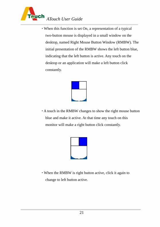
When this function is set On, a representation of a typical
two-button mouse is displayed in a small window on the
desktop, named Right Mouse Button Window (RMBW). The
initial presentation of the RMBW shows the left button blue,
indicating that the left button is active. Any touch on the
desktop or an application will make a left button click
constantly.
A touch in the RMBW changes to show the right mouse button
blue and make it active. At that time any touch on this
monitor will make a right button click constantly.
When the RMBW is right button active, click it again to
change to left button active.
ATouch User Guide
22
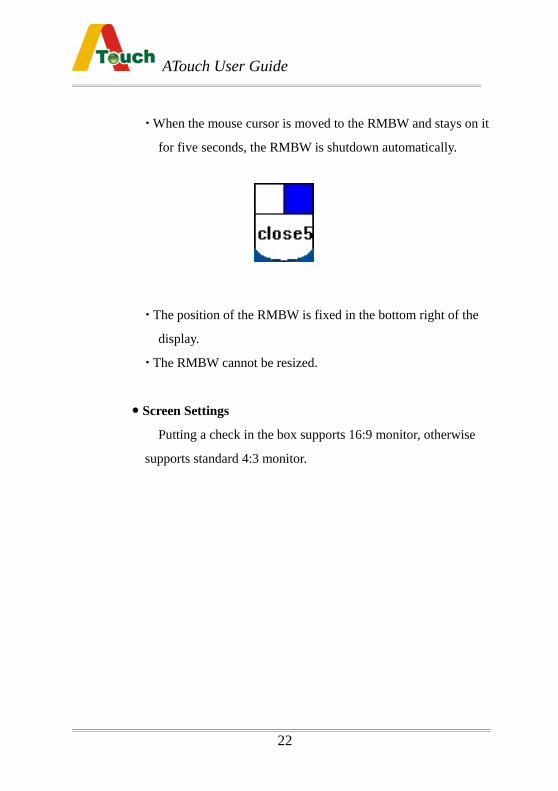
When the mouse cursor is moved to the RMBW and stays on it
for five seconds, the RMBW is shutdown automatically.
The position of the RMBW is fixed in the bottom right of the
display.
The RMBW cannot be resized.
Screen Settings
Putting a check in the box supports 16:9 monitor, otherwise
supports standard 4:3 monitor.
ATouch User Guide
23
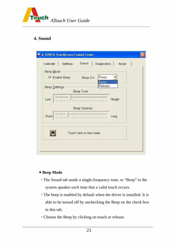
4. Sound
Beep Mode
The Sound tab sends a single-frequency tone, or “Beep” to the
system speaker each time that a valid touch occurs.
The beep is enabled by default when the driver is installed. It is
able to be turned off by unchecking the Beep on the check box
in this tab.
Choose the Beep by clicking on touch or release.
ATouch User Guide
24
Beep Settings
The frequency (Tone) and the Duration of the beep can be
adjusted by moving the appropriate slider in this tab with the
touchscreen or mouse, or by using the keyboard arrow keys.
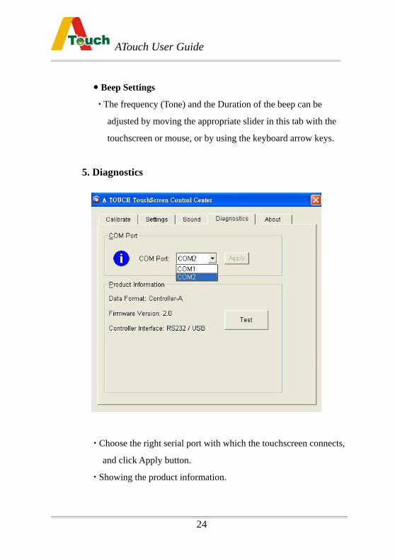
5. Diagnostics
Choose the right serial port with which the touchscreen connects,
and click Apply button.
Showing the product information.
ATouch User Guide
25
6. About The About tab show the version of the driver and provides the link
to ATouch’s web site.
3.2 USB Software Driver Installation for Windows The following installation is applied to
Windows 95/98/Me/2000/XP/NT The complete procedure is divided into two parts: pl2303 and ATouch-2.0.exe.
Step1. Run self-extract file “ATouch USB Drivers.exe” in the driver diskette.
Step2: Installing the pl2303 USB-to-Serial converter driver.
(Use Windows XP for example)
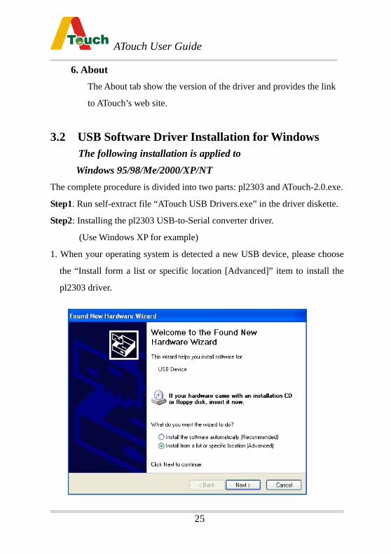
1. When your operating system is detected a new USB device, please choose
the “Install form a list or specific location [Advanced]” item to install the
pl2303 driver.
ATouch User Guide
26
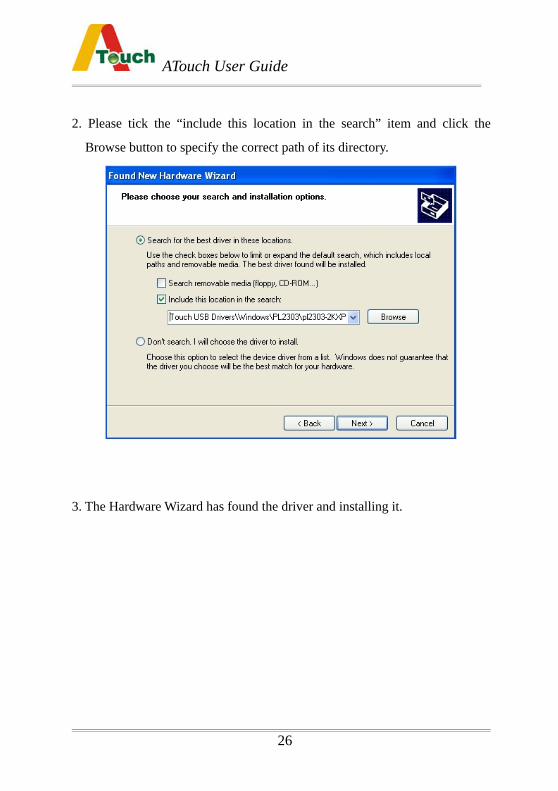
2. Please tick the “include this location in the search” item and click the
Browse button to specify the correct path of its directory.
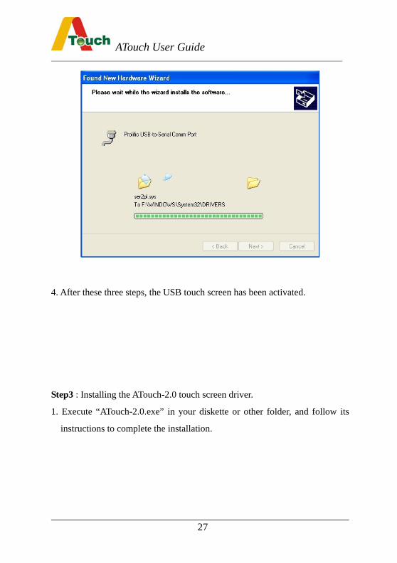
3. The Hardware Wizard has found the driver and installing it.
ATouch User Guide
27
4. After these three steps, the USB touch screen has been activated.
Step3 : Installing the ATouch-2.0 touch screen driver.
1. Execute “ATouch-2.0.exe” in your diskette or other folder, and follow its
instructions to complete the installation.
ATouch User Guide
28
ATouch User Guide
29
ATouch User Guide
30
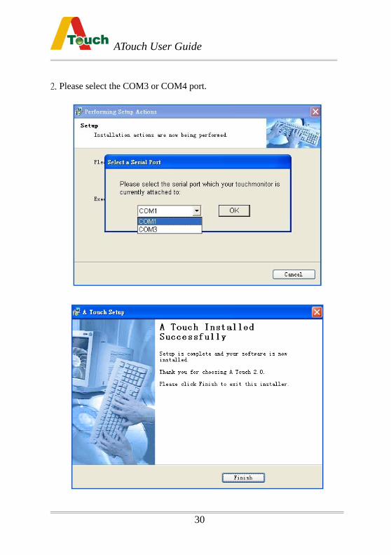
2. Please select the COM3 or COM4 port.
ATouch User Guide
31
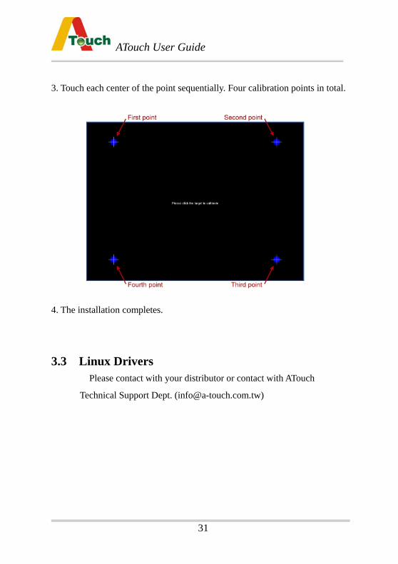
3. Touch each center of the point sequentially. Four calibration points in total.
4. The installation completes.
3.3 Linux Drivers
Please contact with your distributor or contact with ATouch
Technical Support Dept. ([email protected])
ATouch User Guide
32
Chapter 4 Troubleshooting
Before you start troubleshooting, check the following. Make sure your computer and monitor are working normally.
Check that the touchscreen connectors are all inserted correctly.
Make sure if the touchscreen hardware is normal in function. Connect the touch sensor and the controller with the computer. After
the computer power is opened, check the controller. The red LED on
the controller will light and then switch off after three seconds
automatically. When the touch sensor is touched, the LED lights.
That condition means the touchscreen system is normal.
The LED lights constantly, not switch off Check whether the protected film on the touch sensor is removed.
Check whether the touch sensor is very dirty and needs to be cleaned.
The transducers on the touch sensor are out of order during
transportation and movement.
The LED does not light The power-supply key board cable of the touchscreen does not be
connected or not connected tightly enough. Or the key board
connectors have some defects. Remove the touchscreen system from
the computer, and re-connect the key board with the computer to
check if the key board works normally.
ATouch User Guide
33
The touchscreen hardware is normal but no touch response .
If the RS-232 controller is used, check whether its COM port is
identical with the serial port setting in the ATouch Control Center
program . If they are not the same, correct it and retry.
Check whether the device resource of the computer is in conflict
condition. For example, the default IRQ of some network adapters is
3 ,and that conflicts with the IRQ of COM2. Change the IRQ of the
device to the idle one.
The touch position is not accurate. Use the Calibration function of the ATouch Control Center program
to re-align.
If the touch position is not accurate after the calibration, please check
whether the touchscreen driver you use is the newest version.
Maybe there is too much water, dust or other contaminants on the
surface of the touch sensor. Please clean it.
No touch response to the partial area of the touch sensor. Maybe the partial reflectors on the touch sensor surface are covered
with dust that influences the transmission of the acoustic wave.
Please check and clean it.
Maybe the partial reflectors on the touch sensor surface are scratched
by certain hard object. In this case, the touch sensor is not able to be
repaired.
ATouch User Guide
34
The cursor trembles on the screen automatically in untouched condition.
Check whether the setting position of the controller and the
touchscreen cables are set too close to the display’s inverter and the
power supply. Let the controller and the cables far away from them.
Check whether the insulation treatment is done.
Chapter 5 Contact
For any question, please contact with your distributor or
contact with A Touch Technical Support Dept.:


![Coaxial Noncontact Surface Compliance Distribution ... · measurement system can detect muscle contraction using acoustic radiation pressure in WHC 2013 [7]. This system measures](https://img.pdfslide.tips/doc/110x75/5f0e954a7e708231d43ff068/coaxial-noncontact-surface-compliance-distribution-measurement-system-can-detect.jpg)