Embed Size (px)
Citation preview
Journal of Electromagnetic Analysis and Applications, 2013, 5, 243-249 http://dx.doi.org/10.4236/jemaa.2013.56039 Published Online June 2013 (http://www.scirp.org/journal/jemaa)
243
Surface Magnet Gears with a New Magnet Arrangement and Optimal Shape of Stationary Pole Pieces
Tomoyuki Fujita1, Yoshinori Ando2, Kosuke Nagaya2, Masaru Oka3, Takashi Todaka3, Masato Enokizono3, Kazunobu Sugiura1
1Nissei Corporation, Anjo-Aichi, Japan; 2Mechanical System Engineering, Gunma University, Kiryu, Japan; 3Faculty of Engineering, Oita University, Oita, Japan. Email: [email protected] Received April 23rd, 2013; revised May 24th, 2013; accepted June 1st, 2013 Copyright © 2013 Tomoyuki Fujita et al. This is an open access article distributed under the Creative Commons Attribution License, which permits unrestricted use, distribution, and reproduction in any medium, provided the original work is properly cited.
ABSTRACT
In mechanical gear systems, dust, noise, vibration, and tooth wear are generated by frictions among gear teeth, and sup-pressing friction requires lubrication. Magnetic gears transmit torque by magnetic forces without contact and so avoid contact-related problems. The present paper discusses magnet arrangements and the shape of stationary gear teeth to improve transmission torque in surface magnet type magnetic gear transmission mechanisms. Keywords: Magnetic Gear; Stationary Pole Piece; Optimal Shape; Halbach Magnet Arrangement
1. Introduction
Lubricant is prohibited in factories that handle semicon- ductors, liquid crystals, and food, and noise can be prob- lematic in hospitals and offices, for example. Magnetic gears offer non-contact torque transmission without the need for lubricant. Quiet, non-lubricated, high perform- ance magnetic gears consisting of permanent magnet poles have been investigated extensively in recent years. Atallah and Howe [1] and Atallah et al. [2] proposed such gears, and Chau et al. [3], Linni et al. [4], Ikeda et al. [5], and Hirata et al. [6,7], Rasmussen [8] discussed transmission torque. Recently, Hitachi Metal Co. Ltd developed the magnetic gear with efficiency of 95%, but there was no experimental data [9]. Moreover, Hirata et al. presented a hybrid magnetic gear [6,7].
In the above studies, the transmission torque was ana- lyzed by magnetic field analysis, and the results were conformed experimentally. However, experimental stud- ies on magnetic gears with high-speed response and high transmission torque, which are required in practical ap- plication, have not yet been performed. The system under high-speed rotation and strong dynamic magnetic forces becomes unstable because large vibrations will occur due to unbalanced magnetic and centrifugal forces, and so it is difficult to achieve stable high-speed rotation.
The present study is an aim of the practical use of a surface magnet type magnetic gear, and provides the po-
werful (torque of 8 through 15 N·m) and high speed (about 3000 rpm) magnetic gear with practical size. At the first, the gear is actually made for trial purposes, and dynamic transmission torques, high-speed stabilities, and high-speed synchronizations, etc. are examined. How- ever, effects of flux leakages in the stator on the trans- mission torque are large, and the eddy current loss is large. Therefore, the present article provides a new type magnetic gear which prevents eddy current loss. In par- ticular, the optimal shape of the stator gear is investi- gated theoretically. The optimal magnet arrangement is also discussed, because the magnet arrangement is im- portant to high transmission torque in the gear.
2. Magnetic Gear with Beam Type Pole Pieces
2.1. Geometry of the Gear
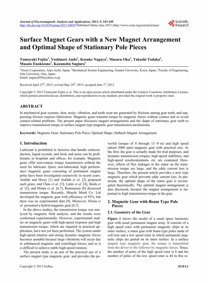
Figure 1 shows the model of a usual space harmonic gear with usual permanent magnet array. It consists of a high speed rotor with permanent magnetic chips at its outer surface, a stator gear with beam type poles made of soft iron and a low speed rotor in which permanent mag- netic chips are pasted on its inner surface. In a surface magnet type magnetic gear, the torque is transmitted from the driver to the follower by magnetic forces. Since, the number of poles of the high speed rotor is 8 and the number of poles of the low speed rotor is 44 in this re-
Copyright © 2013 SciRes. JEMAA
Surface Magnet Gears with a New Magnet Arrangement and Optimal Shape of Stationary Pole Pieces 244
search, the gear ratio is 5.5, and the low-speed rotor is rotated in the opposite direction to the high-speed rotor.
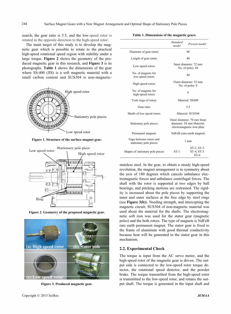
The main target of this study is to develop the mag- netic gear which is possible to rotate to the practical high-speed rotational speed region with stability under a large torque. Figure 2 shows the geometry of the pro- duced magnetic gear in this research, and Figure 3 is its photographs. Table 1 shows the dimensions of the gear where SS-400 (JIS) is a soft magnetic material with a small carbon content and SUS304 is non-magnetic-
High speed rotor
Stationery pole pieces
Low speed rotor
Figure 1. Structure of the surface magnet gear.
Stationary pole piece Low speed rotor
High speed rotor
Ring
Figure 2. Geometry of the proposed magnetic gear.
(a) High speed rotor (b) Stator pole
(c) Low speed rotor
Figure 3. Produced magnetic gear.
Table 1. Dimensions of the magnetic gears.
Standard
model Present model
Diameter of gear (mm) 90
Length of gear (mm) 40
Low-speed rotors Inner diameter: 72 mm
No. of poles: 44
No. of magnets for low-speed rotors
44
High-speed rotors Outer diameter: 52 mm
No. of poles: 8
No. of magnets for high-speed rotors
8
York rings of rotors Material: SS400
Gear ratio 5.5
Shafts of low-speed rotors Material: SUS304
Stationary pole pieces Outer diameter: 70 mm Inner diameter: 54 mm Material: electromagnetic iron plate
Permanent magnets NdFeB (rare-earth magnet)
Gaps between rotors and stationary pole pieces
1 mm
Shapes of stationary pole pieces ST-1 ST-2, ST-3 ST-4, ST-5
ST-6
stainless steel. In the gear, to obtain a steady high-speed revolution, the magnet arrangement is in symmetry about the axis of 180 degrees which cancels unbalance elec- tromagnetic forces and unbalance centrifugal forces. The shaft with the rotor is supported at two edges by ball bearings, and pitching motions are restrained. The rigid-ity is increased about the pole pieces by supporting the inner and outer surfaces at the free edge by steel rings (see Figure 3(b)). Needing strength, and intercepting the magnetic circuit, SUS304 of non-magnetic material was used about the material for the shafts. The electromag- netic soft iron was used for the stator gear (magnetic poles) and the both rotors. The type of magnets is NdFeB rare earth permanent magnet. The stator gear is fixed to the frame of aluminum with good thermal conductivity because heat will be generated in the stator gear in this mechanism.
2.2. Experimental Check
The torque is input from the AC servo motor, and the high-speed rotor of the magnetic gear is driven. The out-put side is connected to the low-speed rotor torque de-tector, the rotational speed detector, and the powder brake. The torque transmitted from the high-speed rotor is transmitted to the low-speed rotor, and rotates the out-put shaft. The torque is generated in the input shaft and
Copyright © 2013 SciRes. JEMAA
Surface Magnet Gears with a New Magnet Arrangement and Optimal Shape of Stationary Pole Pieces 245
the output shaft by giving the load by the powder brake. The input side detector detects the rotational speeds and the torque generated between the motor and the high- speed rotor. The output side detector detects the rota-tional speeds and the torque generated between the low-speed rotor and the powder brake.
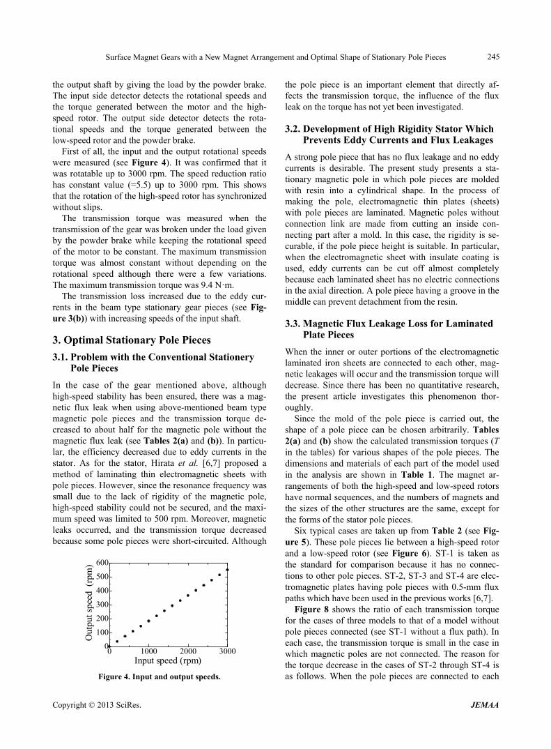
First of all, the input and the output rotational speeds were measured (see Figure 4). It was confirmed that it was rotatable up to 3000 rpm. The speed reduction ratio has constant value (=5.5) up to 3000 rpm. This shows that the rotation of the high-speed rotor has synchronized without slips.
The transmission torque was measured when the transmission of the gear was broken under the load given by the powder brake while keeping the rotational speed of the motor to be constant. The maximum transmission torque was almost constant without depending on the rotational speed although there were a few variations. The maximum transmission torque was 9.4 N·m.
The transmission loss increased due to the eddy cur- rents in the beam type stationary gear pieces (see Fig- ure 3(b)) with increasing speeds of the input shaft.
3. Optimal Stationary Pole Pieces
3.1. Problem with the Conventional Stationery Pole Pieces
In the case of the gear mentioned above, although high-speed stability has been ensured, there was a mag- netic flux leak when using above-mentioned beam type magnetic pole pieces and the transmission torque de- creased to about half for the magnetic pole without the magnetic flux leak (see Tables 2(a) and (b)). In particu- lar, the efficiency decreased due to eddy currents in the stator. As for the stator, Hirata et al. [6,7] proposed a method of laminating thin electromagnetic sheets with pole pieces. However, since the resonance frequency was small due to the lack of rigidity of the magnetic pole, high-speed stability could not be secured, and the maxi- mum speed was limited to 500 rpm. Moreover, magnetic leaks occurred, and the transmission torque decreased because some pole pieces were short-circuited. Although
0 1000 2000 30000
100
200
300
400
500
600
Input speed (rpm)
Out
put s
peed
(rp
m)
Figure 4. Input and output speeds.
the pole piece is an important element that directly af-fects the transmission torque, the influence of the flux leak on the torque has not yet been investigated.
3.2. Development of High Rigidity Stator Which Prevents Eddy Currents and Flux Leakages
A strong pole piece that has no flux leakage and no eddy currents is desirable. The present study presents a sta- tionary magnetic pole in which pole pieces are molded with resin into a cylindrical shape. In the process of making the pole, electromagnetic thin plates (sheets) with pole pieces are laminated. Magnetic poles without connection link are made from cutting an inside con- necting part after a mold. In this case, the rigidity is se- curable, if the pole piece height is suitable. In particular, when the electromagnetic sheet with insulate coating is used, eddy currents can be cut off almost completely because each laminated sheet has no electric connections in the axial direction. A pole piece having a groove in the middle can prevent detachment from the resin.
3.3. Magnetic Flux Leakage Loss for Laminated Plate Pieces
When the inner or outer portions of the electromagnetic laminated iron sheets are connected to each other, mag- netic leakages will occur and the transmission torque will decrease. Since there has been no quantitative research, the present article investigates this phenomenon thor- oughly.
Since the mold of the pole piece is carried out, the shape of a pole piece can be chosen arbitrarily. Tables 2(a) and (b) show the calculated transmission torques (T in the tables) for various shapes of the pole pieces. The dimensions and materials of each part of the model used in the analysis are shown in Table 1. The magnet ar- rangements of both the high-speed and low-speed rotors have normal sequences, and the numbers of magnets and the sizes of the other structures are the same, except for the forms of the stator pole pieces.
Six typical cases are taken up from Table 2 (see Fig-ure 5). These pole pieces lie between a high-speed rotor and a low-speed rotor (see Figure 6). ST-1 is taken as the standard for comparison because it has no connec- tions to other pole pieces. ST-2, ST-3 and ST-4 are elec- tromagnetic plates having pole pieces with 0.5-mm flux paths which have been used in the previous works [6,7].
Figure 8 shows the ratio of each transmission torque for the cases of three models to that of a model without pole pieces connected (see ST-1 without a flux path). In each case, the transmission torque is small in the case in which magnetic poles are not connected. The reason for the torque decrease in the cases of ST-2 through ST-4 is as follows. When the pole pieces are connected to each
Copyright © 2013 SciRes. JEMAA
Surface Magnet Gears with a New Magnet Arrangement and Optimal Shape of Stationary Pole Pieces 246
Table 2. (a) Effects of pole piece shape on the transmission torques; (b) Effects of pole piece shapes on the transmission torques.
ST-1 ST-2 ST-3
(a)
(1) T=20.5 N.m
(2) T=17.5N.m (3) T=18.6N.m
(4) T=14.2 N.m (5) T=20.4 N.m (6)T=17.0 N.m
(7) T=19.4 N.m
(8) T=19.0 N.m (9)T=19.8 N.m
(10)T=19.6N.m
(11)T=19.7N.m (12)T=20.7N.m
ST-4 ST-5 ST-6
(b)
(13)T=20.6N.m
(14)T=20.2N.m (15)T=19.6N.m
(16)T=20.1N.m
(17)T=18.0N.m
(18)T=19.4N.m
(19)T=20.9N.m
(20)T=21.0N.m (21)T=21.7N.m
(22)T=20.5N.m
(23)T=20.5N.m (24)T=20.8N.m
other, the magnetic fluxes through the flux path are short-circuited and the magnetic flux that contributes to the transmission torque decreases, and so the flux leak loss at the time of connecting the perimeter and middle, in order to obtain the strength of magnetic poles, will be 30%. Then, in order to improve the torque transmission efficiency, it is important to consider the shapes of pole
Figure 5. Shapes of stator pole pieces.
Figure 6. Cross section of the proposed gear with improved stator poles and Halbach magnet arrangement. pieces, which affect the magnetic flux leakage. These considerations have not been discussed in previous re- ports. When trying to improve the rigidity of pole pieces made of laminated iron plates for high-speed rotation, the width of the flux path should be increased, thereby de- creasing the transmission torque due to flux leakages, as mentioned above. Therefore, it is difficult to construct magnetic gears with high transmission efficiency using the conventional laminated stator.
3.4. Optimal Design of Pole Pieces
The transmission efficiency can be improved by choos- ing a pole piece of suitable shape. Figure 7 depicts the magnetic flux densities along the line at R = 31 mm from the center (see Figure 6) for the normal case of ST-1 and two typical cases of ST-5 and ST-6.
The transmission efficiency can be improved by choosing a pole piece of suitable shape. The magnetic flux densities in the cases of ST-5 and ST-6 are large in comparison with those of ST-1.
When compared to the ST-5 and ST-6 in Figure 7, much magnetic flux penetrates the pole piece of ST-5. In ST-5, the magnetic flux densities at the air gaps are smaller than those in case of ST-1 because the air gaps between the pole pieces along the central line (R = 31) are larger than those in the case of ST-1. As a result, lar-ger transmission torques are obtained in the case of ST-5, as shown in Figure 8.
On the other hand, in ST-6, since the pole piece be-
Copyright © 2013 SciRes. JEMAA
Surface Magnet Gears with a New Magnet Arrangement and Optimal Shape of Stationary Pole Pieces 247
Angle of the high speed rotor (º)
Mag
net
ic f
lux
den
sity
(T
)
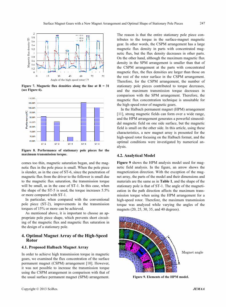
Figure 7. Magnetic flux densities along the line at R = 31 (see Figure 6).
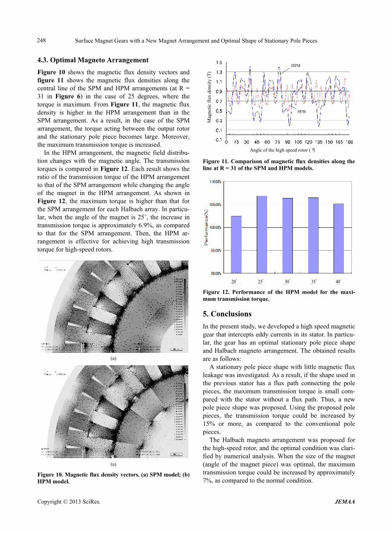
Figure 8. Performance of stationary pole pieces for the maximum transmission torque. comes too thin, magnetic saturation began, and the mag- netic flux in the pole piece is small. When the pole piece is slender, as in the case of ST-6, since the penetration of magnetic flux from the driver to the follower is small due to the magnetic flux saturation, the transmission torque will be small, as in the case of ST-1. In this case, when the shape of the ST-5 is used, the torque increases 5.5% or more compared with ST-1.
In particular, when compared with the conventional pole piece (ST-2), improvements in the transmission torques of 15% or more can be achieved.
As mentioned above, it is important to choose an ap- propriate pole piece shape, which prevents short circuit- ing of the magnetic flux and magnetic flux saturation in the design of a stationary pole.
4. Optimal Magnet Array of the High-Speed Rotor
4.1. Proposed Halbach Magnet Array
In order to achieve high transmission torque in magnetic gears, we examined the flux concentration of the surface permanent magnet (CSPM) arrangement [10]. However, it was not possible to increase the transmission torque using the CSPM arrangement in comparison with that of the usual surface permanent magnet (SPM) arrangement.
The reason is that the entire stationary pole piece con- tributes to the torque in the surface-magnet magnetic gear. In other words, the CSPM arrangement has a large magnetic flux density in parts with concentrated mag- netic flux, but the flux density decreases in other parts. On the other hand, although the maximum magnetic flux density in the SPM arrangement is smaller than that of the CSPM arrangement at the parts with concentrated magnetic flux, the flux densities are larger than those on the rest of the rotor surface in the CSPM arrangement. Therefore, for the CSPM arrangement, the number of stationary pole pieces contributed to torque decreases, and the maximum transmission torque decreases in comparison with the SPM arrangement. Therefore, the magnetic flux concentration technique is unsuitable for the high-speed rotor of magnetic gears.
In the Halbach permanent magnet (HPM) arrangement [11], strong magnetic fields can form over a wide range, and the HPM arrangement generates a powerful sinusoid- dal magnetic field on one side surface, but the magnetic field is small on the other side. In this article, using these characteristics, a new magnet array is presented for the high-speed rotor focusing on the Halbach format, and the optimal conditions were investigated by numerical an- alysis.
4.2. Analytical Model
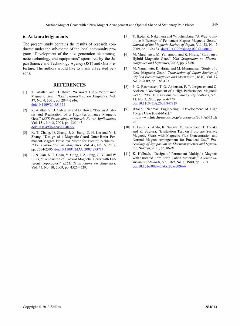
Figure 9 shows the HPM analysis model used for mag- netic field analysis. In the figure, an arrow shows the magnetization direction. With the exception of the mag- net array, the parts of the model and their dimensions and materials are the same as in Table 1, and the shape of the stationary pole is that of ST-1. The angle of the magneti- zation in the path direction affects the maximum trans- mission torque when using the HPM arrangement for a high-speed rotor. Therefore, the maximum transmission torque was analyzed while varying the angles of the magnets (20, 25, 30, 35, and 40 degrees).
Magnet angle
Figure 9. Elements of the HPM model.
Copyright © 2013 SciRes. JEMAA
Surface Magnet Gears with a New Magnet Arrangement and Optimal Shape of Stationary Pole Pieces 248
4.3. Optimal Magneto Arrangement
Figure 10 shows the magnetic flux density vectors and figure 11 shows the magnetic flux densities along the central line of the SPM and HPM arrangements (at R = 31 in Figure 6) in the case of 25 degrees, where the torque is maximum. From Figure 11, the magnetic flux density is higher in the HPM arrangement than in the SPM arrangement. As a result, in the case of the SPM arrangement, the torque acting between the output rotor and the stationary pole piece becomes large. Moreover, the maximum transmission torque is increased.
In the HPM arrangement, the magnetic field distribu- tion changes with the magnetic angle. The transmission torques is compared in Figure 12. Each result shows the ratio of the transmission torque of the HPM arrangement to that of the SPM arrangement while changing the angle of the magnet in the HPM arrangement. As shown in Figure 12, the maximum torque is higher than that for the SPM arrangement for each Halbach array. In particu- lar, when the angle of the magnet is 25˚, the increase in transmission torque is approximately 6.9%, as compared to that for the SPM arrangement. Then, the HPM ar- rangement is effective for achieving high transmission torque for high-speed rotors.
(a)
(a)
Figure 10. Magnetic flux density vectors. (a) SPM model; (b) HPM model.
Angle of the high speed rotor (º)
Mag
neti
c fl
ux d
ensi
ty (
T)
HPM
SPM
Figure 11. Comparison of magnetic flux densities along the line at R = 31 of the SPM and HPM models.
20゜ 25゜ 30゜ 35゜ 40゜
Figure 12. Performance of the HPM model for the maxi- mum transmission torque.
5. Conclusions
In the present study, we developed a high speed magnetic gear that intercepts eddy currents in its stator. In particu- lar, the gear has an optimal stationary pole piece shape and Halbach magneto arrangement. The obtained results are as follows:
A stationary pole piece shape with little magnetic flux leakage was investigated. As a result, if the shape used in the previous stator has a flux path connecting the pole pieces, the maximum transmission torque is small com- pared with the stator without a flux path. Thus, a new pole piece shape was proposed. Using the proposed pole pieces, the transmission torque could be increased by 15% or more, as compared to the conventional pole pieces.
The Halbach magneto arrangement was proposed for the high-speed rotor, and the optimal condition was clari- fied by numerical analysis. When the size of the magnet (angle of the magnet piece) was optimal, the maximum transmission torque could be increased by approximately 7%, as compared to the normal condition.
Copyright © 2013 SciRes. JEMAA
Surface Magnet Gears with a New Magnet Arrangement and Optimal Shape of Stationary Pole Pieces
Copyright © 2013 SciRes. JEMAA
249
6. Acknowledgements
The present study contains the results of research con- ducted under the sub-theme of the local community pro- gram “Development of the next generation electromag- netic technology and equipments” sponsored by the Ja- pan Science and Technology Agency (JST) and Oita Pre- fecture. The authors would like to thank all related per- sons.
REFERENCES [1] K. Atallah and D. Howe, “A novel High-Performance
Magnetic Gear,” IEEE Transactions on Magnetics, Vol. 37, No. 4, 2001, pp. 2844-2846. doi:10.1109/20.951324
[2] K. Atallah, S. D. Calverley and D. Howe, “Design Analy- sis and Realization of a High-Performance Magnetic Gear,” IEEE Proceedings of Electric Power Applications, Vol. 151, No. 2, 2004, pp. 135-143. doi:10.1049/ip-epa:20040224
[3] K. T. Chang, D. Zhang, J. Z. Jiang, C. H. Liu and Y. J. Zhang, “Design of a Magnetic-Geard Outer-Rotor Per- manent-Magnet Brushless Motor for Electric Vehicles,” IEEE Transactions on Magnetics, Vol. 43, No. 6, 2007, pp. 2504-2506. doi:10.1109/TMAG.2007.893714
[4] L. N. Jian, K. T. Chau, Y. Cong, J. Z. Jiang, C. Yu and W. L. Li, “Comparison of Coaxial Magnetic Gears with Dif- ferent Topologies,” IEEE Transactions on Magnetics, Vol. 45, No. 10, 2009, pp. 4526-4529.
[5] T. Ikeda, K. Nakamura and W. Ichinokura, “A Way to Im- prove Efficiency of Permanent-Magnet Magnetic Gears,” Journal of the Magnetic Society of Japan, Vol. 33, No. 2 2009, pp. 130-134. doi:10.3379/msjmag.0901RG8016
[6] M. Muramatsu, M. Yamamoto and K. Hirata, “Study on a Hybrid Magnetic Gear,” 20th Symposium on Electro-magnetics and Dynamics, 2008, pp. 77-80.
[7] M. Yamamoto, K. Hirata and M. Muramatsu, “Study of a New Magnetic Gear,” Transaction of Japan Society of Applied Electromagnetics and Mechanics (AEM), Vol. 17, No. 2, 2009, pp. 188-193.
[8] P. O. Rasmussen, T. O. Andersen, F. T. Jorgensen and O. Nielsen, “Development of a High-Performance Magnetic Gear,” IEEE Transactions on Industry Applications, Vol. 41, No. 3, 2005, pp. 764-770. doi:10.1109/TIA.2005.847319
[9] Hitachi, Neomax Engineering, “Development of High Torque Gear (Beat-Max).” http://www.hitachi-metals.co.jp/press/news/2011/n0721.htm
[10] T. Fujita, Y. Ando, K. Nagaya, M. Enokizono, T. Todaka and K. Sugiura, “Evaluation Test on Prototype Surface Magnetic Gears with Magnetic Flux Concentration and Normal Magnet Arrangement for Practical Use,” Pro- ceedings of Symposium on Electromagnetics and Dynam- ics, Nagoya, 2011, pp. 86-91.
[11] K. Halbach, “Design of Permanent Multipole Magnets with Oriented Rare Earth Cobalt Materials,” Nuclear In- struments Methods, Vol. 169, No. 1, 1980, pp. 1-10. doi:10.1016/0029-554X(80)90094-4


![Spilling the Gears [PIQUE]](https://img.pdfslide.tips/doc/110x75/577ce0591a28ab9e78b31ec5/spilling-the-gears-pique.jpg)