Embed Size (px)
Citation preview

�SUSPENSION - ELECTRONIC LEVEL CONTROL
�1998 Pontiac Bonneville
1998-99 SUSPENSION Electronic - Level Control - "C", "G" & "H" Bodies GM
Aurora, Bonneville, Eighty Eight, LeSabre, LSS, Park Avenue, Riviera
MODEL IDENTIFICATION
MODEL IDENTIFICATION�������������������������������������������������������������������������������������������������������������������������������������������
Body Code (1) Model
"C" .................................................... Park Avenue"G" ............................................... Aurora & Riviera"H" ............... Bonneville, Eighty Eight, LeSabre, LSS & Regency
(1) - Vehicle body code is fourth character of VIN.�������������������������������������������������������������������������������������������������������������������������������������������
NOTE: Bonneville is also equipped with a Computer Command Ride/Real-Time Damping (CCR/RTD) electronic suspension. For information on this system, see ELECTRONIC - REAL TIME DAMPING - BONNEVILLE article. In some literature, Computer Command Ride/Real Time Damping (CCR/RTD) system may be referred to as simply CCR or RTD.
DESCRIPTION
The Electronic Level Control (ELC) system automaticallyraises or lowers rear of vehicle to correct ride height (curb height),compensating for loads added to or removed from vehicle. Systemconsists of a compressor, air drier (desiccant) exhaust (vent)solenoid, compressor relay, height sensor, air adjustable shocks,pressure limiter and connecting air lines. Air drier (mounted oncompressor) contains moisture-absorbing dry chemical and valves thatmaintain minimum system air pressure at about 7-14 psi (.49-.98kg/cm
�
).
OPERATION
SYSTEM OPERATION
When ride height decreases due to weight being added tovehicle, height sensor arm assembly rotates upward in relation toheight sensor. See Fig. 1. This activates a timing circuit in heightsensor. After a delay of 17-27 seconds, height sensor groundscompressor relay, turning on compressor. Air is then pumped into theshock absorbers, raising vehicle. Delay prevents system from operatingduring normal changes in ride height that occur during driving. Asvehicle rises, height sensor rotates downward. When vehicle rises towithin one inch (25.4 mm) of curb height, height sensor opens groundcircuit to compressor relay, turning compressor off. When ride height increases due to weight being removed fromvehicle, height sensor arm assembly rotates downward. This activatesthe timing circuit in height sensor. After a delay of 17-27 seconds,height sensor grounds exhaust solenoid valve circuit, causing air tobe vented from shock absorbers, lowering vehicle. When vehicle lowers

to within 1" (25.4 mm) of curb height, height sensor opens exhaustsolenoid valve circuit, causing exhaust solenoid valve to close. To ensure system is operating with at least minimum airpressure, height sensor commands an air replenishment cycle each timeignition is turned on. An internal timer circuit is activated whenignition is turned on. After a delay of about 35-45 seconds,compressor turns on for 3-5 seconds to ensure residual system pressureexists. If weight is added to or removed from vehicle during 35-45second delay, air replenishment cycle will be overridden and vehiclewill rise or lower after normal time delay. Voltage is applied to compressor, compressor relay, inflatortimer and height sensor at all times. This allows system to vent ifload is removed with ignition off. Height sensor limits compressoroperation or exhaust solenoid energized time to about 4 1/2 and 7 1/2minutes. Time limit is necessary to prevent continuous compressoroperation in case of air leak or continuous exhaust solenoidoperation. Turning ignition switch from OFF to ON position resetscompressor operation or exhaust solenoid valve energized time.
COMPONENT OPERATION
Air Adjustable Shocks Air adjustable shock absorber is a conventional shockenclosed in an air chamber that extends when air pressure in chamberincreases.
Air Drier Air drier, attached to compressor outlet, absorbs moisturefrom air being delivered to air adjustable shock absorbers. Air driercontains a valve that maintains a minimum air pressure of 7-14 psi (.49-.98 kg/cm
�
) in shock absorbers.
Compressor Compressor provides air pressure for system operation.Compressor head casting contains intake and exhaust valves, andexhaust valve solenoid. Compressor is located on right rear underbody,behind wheelwell.
Compressor Relay When compressor relay is grounded by height sensor, voltageis supplied to compressor. Compressor relay is located in relay centerunder rear seat.
Exhaust Solenoid Valve Exhaust solenoid valve, located in compressor head assembly,exhausts air from system and limits compressor output pressure.
Height Sensor Height sensor, mounted to underbody frame in rear of vehicle,links body to right rear suspension arm. Sensor controls groundcircuits of compressor relay and exhaust solenoid valve.
ADJUSTMENTS
HEIGHT SENSOR
NOTE: Optional Height Sensor Adjustment Tool (J-34825) can be used to adjust height sensor. Follow tool manufacturer’s instructions.
1) Park vehicle on level surface. Ensure fuel tank is full.If necessary, simulate full tank by adding about 7 lbs. (3.2 kg) of

weight to rear of vehicle for each gallon of fuel that is not in tank.Ensure vehicle is unloaded and tire inflation pressure is correct.Move front seats rearward. 2) Turn ignition on to activate ELC system. Bounce rear ofvehicle 3 times to normalize suspension. Measure 23 1/2" (600 mm) fromcenter of rear wheel towards front of vehicle. See Fig. 2. Measuretrim/rear ride height from this point. 3) If rear ride height varies by more than 3/4" (19 mm) fromside to side or is lower than 9" (229 mm), repair suspension problembefore continuing procedure. If rear ride height is withinspecification, height sensor is adjusted correctly.
NOTE: Height sensor can be adjusted a total of 5 degrees. One degree of change at height sensor results in a 1/4" (6 mm) change in height at rear bumper.
4) If rear ride height is not within specification, loosenlock bolt on sensor actuating arm. See Fig. 1. Move plastic arm upwardor downward as necessary to increase or decrease rear ride height. Toincrease rear ride height, move plastic arm upward. To decrease rearride height, move plastic arm downward. Tighten lock bolt.
Fig. 1: Adjusting Height SensorCourtesy of General Motors Corp.
Fig. 2: Measuring Rear Ride HeightCourtesy of General Motors Corp.

RIDE HEIGHT
NOTE: See RIDE HEIGHT in WHEEL ALIGNMENT SPECIFICATIONS & PROCEDURES article in WHEEL ALIGNMENT section.
TROUBLE SHOOTING
SYSTEM OPERATION
Vehicle Loaded, Will Not Rise Check for leaks in air lines, fittings or shock absorbers,pinched lines between compressor and shock absorbers, defective heightsensor, inoperative compressor, and loose or damaged electricalconnections to sensor or compressor.
Vehicle Rises When Loaded, Then Leaks Down Check for severe leak in lines, fittings or shock absorbers,and internal leak in compressor.
Vehicle Rises Partially When Loaded Check for out-of-adjustment height sensor and defectivecompressor wiring.
Vehicle Rises When Loaded, Leaks Down When Driving Check for defective drier or compressor, pinched air lines,and/or leaks in fittings or air lines.
Vehicle Rides High Check for out-of-adjustment height sensor, plugged air drieror pinched air lines, and poor electrical connections.
DIAGNOSIS & TESTING
NOTE: Perform BASIC SYSTEM OPERATIONAL TEST before proceeding with ELC system testing. System is tested based upon symptoms. For ELC testing, see ELC SYSTEM SYMPTOM table.
ELC SYSTEM SYMPTOM�������������������������������������������������������������������������������������������������������������������������������������������
Symptom Test No.
Rear Of Vehicle Low .............................................. 1Rear Of Vehicle High ............................................. 2Compressor Runs For Maximum Time (7 Mins.) Then Turns Off; VehicleDoes Not Reach Proper Height ..................................... 3Compressor Cycles On And Off Frequently, No Air Leaks Present .... 3Compressor Does Not Run For 3-5 Seconds After Ignition On For 35-55Seconds .......................................................... 3Compressor Runs Excessively .................................... (1)
(1) - Check for disconnected/damaged air lines or shocks. Perform ELC SYSTEM CHECK under BASIC SYSTEM OPERATIONAL TEST.�������������������������������������������������������������������������������������������������������������������������������������������
BASIC SYSTEM OPERATIONAL TEST
ELC System Check 1) Ensure height sensor and link assembly are in goodcondition before performing system operation test. Place vehicle onflat surface. Measure distance from ground to rocker panel in front of

rear wheelwell opening. See Fig. 2. 2) Turn ignition on. Add 300-350 lbs. (136-159 kg) of weightto rear of vehicle. After 17-27 second delay, compressor should turnon and vehicle should start to rise. Vehicle should rise to within3/4" (19 mm) of measurement made in step 1). 3) Remove load from vehicle. After 17-27 second delay,vehicle should start to lower. Within 3 1/2 minutes, exhaust shouldstop and vehicle should be within 3/4" (19 mm) of measurement made instep 1). If ELC system does not function as specified, performappropriate test. See ELC SYSTEM SYMPTOM table.
NOTE: System leak test determines if a leak exists, and if leak is internal or external to compressor.
Residual Air Pressure Test 1) Install Pressure Gauge (J-22124-B) and Adapter (J-22124-91) to air drier and shock absorber. See Fig. 3. Open shutoff/togglevalve. 2) Disconnect link from height sensor, and move sensor armup. Air compressor should operate, inflating one shock absorber. Movesensor arm down. Air compressor should stop and air should escape.Allow vehicle to go down as far as possible. 3) Connect link to height sensor. Read pressure gauge. Ifpressure gauge reads less than 7 psi (.5 kg/cm
�
), replace air drier.Reconnect all air lines and check for leaks.
Fig. 3: Checking System For LeakageCourtesy of General Motors Corp.
SYMPTOM TESTS
* PLEASE READ THIS FIRST *

NOTE: To identify circuits and wire colors referenced in teting, see WIRING DIAGRAMS. After repairs are complete, recheck system operation. See ELC SYSTEM CHECK under BASIC SYSTEM OPERATIONAL TEST under DIAGNOSIS & TESTING.
TEST 1: REAR OF VEHICLE LOW
1) Turn ignition on, with engine off. Add about 300 lbs. (136kg) to rear of vehicle. Allow 27 seconds for air compressor to startand inflate shocks. If vehicle rear rises and does not leak, go tonext step. If rear of vehicle does not rise or leaks down, go to step4). 2) If vehicle rises to proper level within 30 seconds, ELCsystem is okay. If not, go to next step. 3) Adjust height sensor. See HEIGHT SENSOR under ADJUSTMENTS. 4) If air compressor operated when weight was added, go tostep 20). If air compressor did not operate when weight was added, goto next step. 5) Turn ignition off. Disconnect height sensor harnessconnector. Turn ignition on, with engine off. Using a fused jumperwire, jumper height sensor harness terminal "B" (Yellow wire) toground. If air compressor operates, go to TEST 3. If air compressordoes not operate, go to next step. 6) Turn ignition off. Reconnect height sensor harnessconnector. Remove ELC relay. Relay is located under rear seat. Turnignition on, with engine off. Check voltage between ground and relayterminal socket No. 85. If battery voltage is present, go to step 8).If battery voltage is not present, go to next step. 7) Check for open ELC fuse, located in fuse/relay block.Replace as necessary. If fuse is okay, repair open in circuit betweenfuse/relay block and rear electrical center. 8) Turn ignition off. Check voltage between ground and relayterminal socket No. 30. If battery voltage is present, go to step 10).If battery voltage is not present, go to next step. 9) Check for open ELC fuse or circuit breaker. Replace asnecessary. If fuse or circuit breaker is okay, repair open in circuitto electrical center. 10) Turn ignition off. Connect voltmeter between ELC relayterminal sockets No. 85 and 86. Turn ignition on, with engine off. Ifbattery is present after 17-27 seconds, go to step 12). If batteryvoltage is not present after 17-27 seconds, go to next step. 11) Check for poor connection at height sensor connectorterminal "B" or open in circuit No. 321 (Yellow wire). Repair asnecessary. If connection and circuit are okay, perform HEIGHTSENSORunder ADJUSTMENTS. 12) Using a fused (30-amp) jumper wire, jumper relay terminalsockets No. 30 and 87. If air compressor operates, go to next step. Ifair compressor does not operate, go to step 14). 13) Replace ELC relay. 14) Leave jumper wire connected. Disconnect air compressorharness connector. Check voltage between harness connector terminal"B" and ground. If battery voltage is present, go to step 16). Ifbattery voltage is not present, go to next step. 15) Check for poor connection at rear of power distributioncenter connectors C1 and C2 or connector C4 at relay center. SeeWIRING DIAGRAMS. Repair as necessary. If connections are okay, repairopen in circuit between ELC relay and air compressor motor. 16) Leave jumper wire connected. Check voltage at aircompressor terminals "B" and "D". If battery voltage is present, go tostep 18). If battery voltage is not present, go to next step. 17) Repair open in circuit between air compressor and ground. 18) Disconnect jumper wire. Install ELC relay. Connect jumperwire between air compressor terminal "D" and ground. Connect another

fused jumper wire between air compressor terminal "B" and batteryvoltage. If air compressor operates, repeat step 1). If air compressordoes not operate, go to next step. 19) Replace air compressor. 20) Check rear shock absorbers for leaking air sleeve.Perform RESIDUAL AIR PRESSURE TEST. Check kinked and pinched airlines. Check for disconnected sir line to air compressor or shockabsorbers. Check all fitting for leaks using a soap and watersolution. Repair leak or damage. If leak or damage was not found, goto next step. 21) Disconnect air line from air drier. Connect PressureGauge (J-22124-91) and Adapter (J-22124-B) between air drier. Closetoggle switch. Disconnect air compressor harness connector. Jumpercompressor terminal "D" to ground. Jumper compressor terminal "B" tobattery positive. Allow compressor to operate until air pressurereaches 100 psi (7 kg/cm
�
). Disconnect jumpers when pressure isreached. If pressure is reached, go to step 23). If pressure cannot bereached, go to next step. 22) Replace air compressor. 23) If air pressure holds at 100 psi (7 kg/cm
�
), go to nextstep. If air pressure does not hold, check air compressor for leak. 24) Check for binding rear shock absorber. Replace asnecessary.
TEST 2: REAR OF VEHICLE HIGH
1) Check height sensor adjustment. If height sensor has beenadjusted, go to step 3). If height sensor needs to be adjusted, go tonext step. 2) Adjust height sensor. See HEIGHT SENSOR under ADJUSTMENTS.If problem is not corrected, go to next step. 3) Raise vehicle. Vehicle must be raised on a drive-on hoistor supported under rear axle. Full vehicle weight must be on rearsuspension. Disconnect air line from air drier. If air vents fromline, go to step 5). If air does not vent from line, go to next step. 4) Check for binding in shock absorber. Replace as necessary.If shock absorber is okay, replace air line. 5) Reconnect air line to air drier. Disconnect link fromheight sensor. Raise height sensor lever. If air compressor operates,go to step 7). If air compressor does not operate, go to next step. 6) Check ELC fuse or circuit breaker. Replace as necessary.If fuse or circuit breaker is okay, check for open in circuit betweenfuse or circuit breaker to height sensor. See WIRING DIAGRAMS. Ifcircuit is okay, go to TEST 3. 7) Raise rear of vehicle as much as possible by holdingheight sensor arm up. Reconnect height sensor link. Disconnect aircompressor harness connector. Check voltage at air compressor harnessconnector terminal "A" and ground. If battery voltage is present, goto step 9). If battery voltage is not present, go to next step. 8) Check for poor connection at power distribution centerconnectors C1 and C2 and relay center connector C4. If connections areokay, repair open in circuit between power distribution center andrelay center. 9) Cycle ignition switch. Check voltage between aircompressor harness connector terminals "A" and "C". If battery voltageis present after 17-27 seconds (height sensor delay) after ignitionwas turned on, go to step 11). If battery voltage is still not presentafter 7 minutes, go to next step. 10) Check for open in circuit between air compressor andheight sensor. Check for poor connection at power distribution centerconnectors C1 and C2. Repair as necessary. If circuit and connectionsare okay, go to TEST 3. 11) Replace air compressor head.

TEST 3: HEIGHT SENSOR TEST
1) Disconnect ELC height sensor connector. Turn ignition on,with engine off. Check voltage between ground and ELC height sensorharness connector terminal "C". If battery voltage is present, go tostep 3). If battery voltage is not present, go to next step. 2) Repair open in circuit (Orange wire) between powerdistribution and air compressor. 3) Check voltage between ELC height sensor terminals "A" and"C". If battery voltage is present, go to step 5). If battery voltageis not present, go to next step. 4) Repair open in circuit (Black wire) between air compressorand ground. 5) Check voltage between ELC height sensor harness connectorterminals "A" and "D". If battery voltage is present, go to step 7).If battery voltage is not present, go to next step. 6) Repair open in circuit (Brown wire) between height sensorand power distribution center. 7) Check ELC height sensor harness connector contact. Repairas necessary. If terminal contact is okay, cycle ignition switch againand return to ON position. If air compressor operates for 3-5 secondsafter a 35-55 second delay, go to step 9). If air compressor does notoperate, go to next step. 8) Replace ELC height sensor. 9) Raise vehicle. Ensure rear wheels are supported as closeas possible to trim height dimension. Disconnect link from ELC heightsensor. Move height sensor arm upward. If air compressor operatesafter a 17-27 second delay, go to step 11). If not, go to next step. 10) Replace ELC height sensor. 11) Move height sensor arm down slightly until air compressorstops. If compressor stops, go to step 13). If compressor does notstop, go to next step. 12) Replace ELC height sensor. 13) Move height sensor arm downward. If air escapes from aircompressor after a 17-27 delay (vehicle begins to lower), go step 15).If not, go to next step. 14) Replace ELC height sensor. 15) Adjust ELC height sensor. See ADJUSTMENTS.
REMOVAL & INSTALLATION
* PLEASE READ THIS FIRST *
CAUTION: When battery is disconnected, vehicle computer and memory systems may lose memory data. Driveability problem may exist until computer systems have completed a relearn cycle. Before disconnecting battery, see COMPUTER RELEARN PROCEDURES article in GENERAL INFORMATION.
AIR DRIER
Removal Disconnect high pressure line by turning spring clip 90degrees and removing tube assembly. Disconnect air drier fromcompressor by turning spring clip and sliding drier and "O" ring fromcompressor head assembly. See Fig. 4.
Installation Lubricate "O" ring, and install in port of compressor head.Install retainer spring to its original position. Install air drier oncompressor head assembly. If difficulty arises when installing air
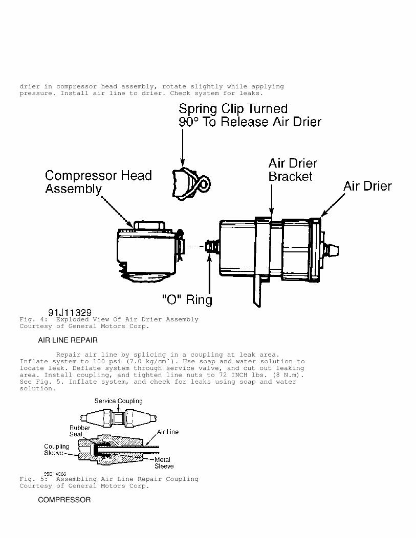
drier in compressor head assembly, rotate slightly while applyingpressure. Install air line to drier. Check system for leaks.
Fig. 4: Exploded View Of Air Drier AssemblyCourtesy of General Motors Corp.
AIR LINE REPAIR
Repair air line by splicing in a coupling at leak area.Inflate system to 100 psi (7.0 kg/cm
�
). Use soap and water solution tolocate leak. Deflate system through service valve, and cut out leakingarea. Install coupling, and tighten line nuts to 72 INCH lbs. (8 N.m).See Fig. 5. Inflate system, and check for leaks using soap and watersolution.
Fig. 5: Assembling Air Line Repair CouplingCourtesy of General Motors Corp.
COMPRESSOR

Removal Disconnect negative battery cable. Disconnect compressorelectrical connectors. Disconnect air lines as necessary. Removecompressor bracket mounting nuts or bolts. Remove compressor andbracket assembly from vehicle.
Installation To install, reverse removal procedure. Tighten compressorbracket mounting nuts or bolts to specification. See TORQUESPECIFICATIONS table. Turn ignition on and allow system to cycle.Check for leaks using soap and water solution.
COMPRESSOR HEAD ASSEMBLY
Removal & Installation Remove air drier assembly. See AIR DRIER. Remove compressorhead bolts. Remove compressor head assembly. See Fig. 6. To install,reverse removal procedure. Tighten compressor head bolts in sequenceto specification. See Fig. 7. See TORQUE SPECIFICATIONS table.
Fig. 6: Removing Compressor Head AssemblyCourtesy of General Motors Corp.

Fig. 7: Compressor Head Bolt Tightening SequenceCourtesy of General Motors Corp.
EXHAUST SOLENOID

Exhaust solenoid is replaced as an assembly with aircompressor head. See COMPRESSOR HEAD ASSEMBLY.
HEIGHT SENSOR
Removal Disconnect negative battery cable. Raise and support vehicle.Disconnect height sensor harness connector. Disconnect height sensorlink from height sensor actuating arm. Remove height sensor screws andremove height sensor.
Installation To install, reverse removal procedure. Tighten height sensorscrews to specification. See TORQUE SPECIFICATIONS table. Adjustheight sensor. See HEIGHT SENSOR under ADJUSTMENTS.
TORQUE SPECIFICATIONS
TORQUE SPECIFICATIONS�������������������������������������������������������������������������������������������������������������������������������������������
Application INCH Lbs. (N.m)
Compressor Bracket Mounting Bolt "G" Body .................................................. 62 (7)Compressor Bracket Mounting Nut "C" & "H" Bodies ......................................... 89 (10)Compressor Head Bolt .................................... (1) 53 (6)Compressor-To-Compressor Bracket Screw ...................... 26 (3)Height Sensor Link Nut "C" & "H" Bodies ......................................... 97 (11) "G" Body ................................................. 89 (10)Height Sensor Screw "C" & "H" Bodies ........................................ 22 (2.5) "G" Body ................................................ 22 (2.5)
(1) - Tighten in sequence. See Fig. 7.�������������������������������������������������������������������������������������������������������������������������������������������
WIRING DIAGRAMS

Fig. 8: Electronic Level Control (ELC) Wiring Diagram (Aurora &Riviera - 1998)
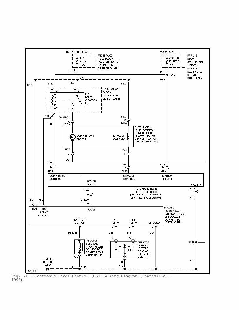
Fig. 9: Electronic Level Control (ELC) Wiring Diagram (Bonneville -1998)

Fig. 10: Electronic Level Control (ELC) Wiring Diagram (Eighty Eight,LeSabre, LSS & Regency - 1998)

Fig. 11: Electronic Level Control (ELC) Wiring Diagram (Park Avenue -1998)
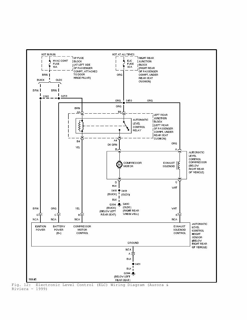
Fig. 12: Electronic Level Control (ELC) Wiring Diagram (Aurora &Riviera - 1999)

Fig. 13: Electronic Level Control (ELC) Wiring Diagram (Bonneville -1999)

Fig. 14: Electronic Level Control (ELC) Wiring Diagram (Eighty Eight,LeSabre & LSS - 1999)

Fig. 15: Electronic Level Control (ELC) Wiring Diagram (Park Avenue -1999)