Embed Size (px)
Citation preview
SWIRLMAX®
VFM4200Vortex Flowmeter
OUTLINE
SWIRLMAX® is a 2-wire, all-in-one type vortex flowmeter with
temperature and pressure sensors.
The VFM4200 can easily correct flow measurements of steam and
gases for temperature and pressure. There is no need for additional
sensors and correctors.
The VFM4200 is ideal for managing the energy of steam and gases.
FEATURES
❏ Measuring various fluids
Steam, gases, and liquids
❏ Flow correction for saturated steam by temperature as standard
The VFM4200 contains a temperature sensor and stores a table
of saturated steam density in the amplifier.
The flowmeter measures the flow rate of saturated steam,
corrects it by temperature, and outputs the result. It is easy to
measure the mass flow rate of saturated steam.
❏ Optional pressure sensor
A pressure sensor can be mounted as an option. The VFM4200
can easily correct flow measurements of steam and gases by
temperature and pressure. There is no need for additional sensors
and correctors.
❏ Corrosion-resistant all-stainless-steel construction
All wetted parts are made of welded stainless steel and are
robust, with excellent corrosion and heat resistance.
❏ Reduced diameters available for flange type
Flange type flowmeters with reduced meter sizes are available for
measuring low flow rates.
The diameter can be reduced by up to two steps from the
connection size.
❏ Advanced vortex frequency detection (AVFD) ensures stable
reading
The original AVFD technology eliminates external disturbances
and ensures stable, reliable readings.
❏ Robust construction
Robust, maintenance-free construction with no moving parts
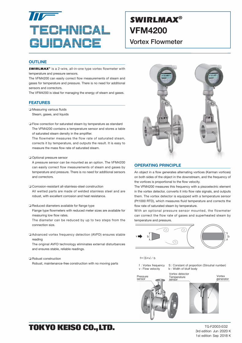
OPERATING PRINCIPLE
An object in a flow generates alternating vortices (Karman vortices)
on both sides of the object in the downstream, and the frequency of
the vortices is proportional to the flow velocity.
The VFM4200 measures this frequency with a piezoelectric element
in the vortex detector, converts it into flow rate signals, and outputs
them. The vortex detector is equipped with a temperature sensor
(Pt1000 RTD), which measures fluid temperature and corrects the
flow rate of saturated steam by temperature.
With an optional pressure sensor mounted, the f lowmeter
can correct the flow rate of gases and superheated steam by
temperature and pressure.
f=(S×v)/ b
f : Vortex frequency S : Constant of proportion (Strouhal number)v : Flow velocity b : Width of bluff body
bbv
Pressuresensor
Vortex detectorTemperaturesensor
Vortexgenerator
TG-F2003-E02Jun 2020Sep 2018
3rd edition1st edition
KK
SWIRLMAX® VFM4200 Vortex Flowmeter
2 TOKYO KEISO CO., LTD. TG-F2003-E02
STANDARD SPECIFICATIONS
General Specifications
● Meter size
• Flange type : 15, 25, 40, 50, 80, 100, 150, 200, 250,
and 300 mm
• Wafer type : 15, 25, 40, 50, 80, and 100 mm
● Protection class : IP66/67 (IEC 60529)
● Ambient temperature : −40 to +85ºC
* Refer to “Explosionproof Specifi cations”
for explosionproof products.
Fluid Specifications
● Measured fl uid : Gas, steam, and liquid
● Temperature : −40 to +240ºC
* Refer to “Explosionproof Specifi cations”
for explosion proof products.
● Pressure : Up to fl ange rating (max. 10 MPa)
● Viscosity : Up to 10 mPa·s
● Reynolds number (Re) : 10,000 or higher
Sensor Specifications
● Wetted parts material : Stainless steel (316L)
[Metering tube, fl ange, vortex detector, and gasket for vortex detector]
● Process connection : Flange or wafer (inserted between pipe
fl anges)
● Flange : JIS10K/20K
ASME class 150/300/600
● Temperature sensor : Built-in Pt1000 RTD (standard)
● Pressure sensor : Pressure sensor integrated (optional)
● Connection box material : Aluminum alloy (For remote type)
● Connection cable length : Max. 50 m (For remote type)
Converter Specifications
● Housing material : Aluminum alloy
● Painting : Two-layer coating (Epoxy / Polyester)
● Color : Gray (converter housing)
Jade green (converter cover)
● Cable entry : G1/2 female, 1/2 NPT female, or M20
watertight gland
● Power supply : 24 V DC (12 to 36 V DC)
* Refer to “Explosionproof Specifi cations”
for explosionproof products.
● Display : LCD
2 screens can be alternated, up to 3 lines
on each screen
Selectable among flow rate, total flow,
temperature, flow velocity, vortex fre
quency, and pressure (optional)
● Output
Current output
• Output : 2-wire, 4–20 mA DC
• Allowable load resistance
: R=(E−12) / 0.022Ω (E=Power voltage (V))
Contact output
• Output : Selectable among pulse output, frequency
output, status output, and limit switch
• Output type : Open collector (normally closed) or
NAMUR output
• Pulse rate : Max. 1,000 Hz (pulse output and fre-
quency output)
• Pulse width : 0.5 to 2,000 ms
• Load rating : Max. 36 V DC, 100 mA (open collector
output)
* Refer to “Explosionproof Specifications”
for explosionproof products.
● Flow rate correction function
: Flow correction of saturated steam by
temperature (standard)
Flow correction of superheated steam
and gas by temperature and pressure
(optional)
● HART communication : HART7 (standard)
● Damping time constant (63% response)
: 0 to 100 s (variable)
● Test function : Simulated current output and contact
output
● Burnout : Either 22 mA or 3.55 mA can be output at
error
Accuracy (under standard conditions)
• Re ≥ 20,000 : ±0.75% of reading (liquid)
±1% of reading (gas and steam)
• 10,000 < Re < 20,000
: ±2% of reading (liquid, gas, and steam)
[When corrected by temperature and pressure]
• Re ≥ 20,000 : ±1.5% of reading (gas and steam)
• 10,000 < Re < 20,000
: ±2.5% of reading (gas and steam)
* These values are display accuracy.
* Add ±0.1% of full scale to these values to obtain current output
accuracy.
• Repeatability : ±0.1%
Explosionproof Specifications
● JPN, ATEX, IECEx
* For further details, refer to “Explosionproof Specifications” on
pages 13 to 17.
Measurable Flow Rate Range
● Measurable minimum and maximum fl ow velocities
[ρ: Fluid density (unit: kg/m3)]Min. velocity Max. velocity
Liquid
The largest value among:
• 0.5 × (998/ρ) 0.5
• Flow velocity when Re is 10,000
• 0.3 m/s
The smallest value among:
• 7 × (998/ρ) 0.47
• 10 m/s
Gas,
steam
The largest value among:
• 6 × (1.204/ρ) 0.5
• Flow velocity when Re is 10,000
• 2 m/s (3 m/s for 15-mm meter
size)
The smallest value among:
• 7 × (998/ρ) 0.47
• 80 m/s
(45 m/s for 15-mm meter size,
70 m/s for 25-mm meter size)
● Measurable fl ow rate range for water
[Temperature: 20ºC]
Meter size Flow rate range (m3/h)
15 (0.46)
0.91 to 5.04
25 (0.82)
1.36 to 11.3
40 (2.05)
2.15 to 28.4
50 3.54 to 49.2
80 7.75 to 107
100 13.4 to 185
150 30.2 to 419
200 56.7 to 787
250 90.5 to 1260
300 128 to 1772
Note: Values in parentheses are the minimum flow rates at an accuracy of ±2.0%. Other values are the minimum and the maximum fl ow rates at an ac curacy of ±0.75%.
SWIRLMAX® VFM4200 Vortex Flowmeter
TOKYO KEISO CO., LTD. 3TG-F2003-E02
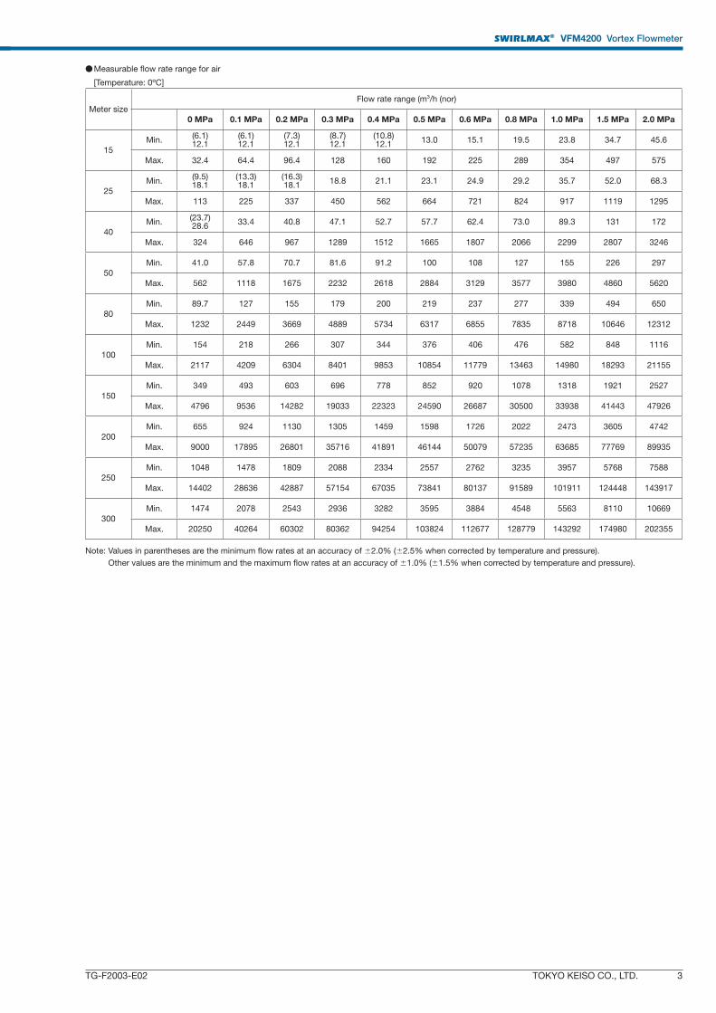
● Measurable fl ow rate range for air
[Temperature: 0ºC]
Meter size
Flow rate range (m3/h (nor)
0 MPa 0.1 MPa 0.2 MPa 0.3 MPa 0.4 MPa 0.5 MPa 0.6 MPa 0.8 MPa 1.0 MPa 1.5 MPa 2.0 MPa
15
Min.(6.1)12.1
(6.1)12.1
(7.3)12.1
(8.7)12.1
(10.8)12.1
13.0 15.1 19.5 23.8 34.7 45.6
Max. 32.4 64.4 96.4 128 160 192 225 289 354 497 575
25
Min.(9.5)18.1
(13.3)18.1
(16.3)18.1
18.8 21.1 23.1 24.9 29.2 35.7 52.0 68.3
Max. 113 225 337 450 562 664 721 824 917 1119 1295
40
Min.(23.7)28.6
33.4 40.8 47.1 52.7 57.7 62.4 73.0 89.3 131 172
Max. 324 646 967 1289 1512 1665 1807 2066 2299 2807 3246
50
Min. 41.0 57.8 70.7 81.6 91.2 100 108 127 155 226 297
Max. 562 1118 1675 2232 2618 2884 3129 3577 3980 4860 5620
80
Min. 89.7 127 155 179 200 219 237 277 339 494 650
Max. 1232 2449 3669 4889 5734 6317 6855 7835 8718 10646 12312
100
Min. 154 218 266 307 344 376 406 476 582 848 1116
Max. 2117 4209 6304 8401 9853 10854 11779 13463 14980 18293 21155
150
Min. 349 493 603 696 778 852 920 1078 1318 1921 2527
Max. 4796 9536 14282 19033 22323 24590 26687 30500 33938 41443 47926
200
Min. 655 924 1130 1305 1459 1598 1726 2022 2473 3605 4742
Max. 9000 17895 26801 35716 41891 46144 50079 57235 63685 77769 89935
250
Min. 1048 1478 1809 2088 2334 2557 2762 3235 3957 5768 7588
Max. 14402 28636 42887 57154 67035 73841 80137 91589 101911 124448 143917
300
Min. 1474 2078 2543 2936 3282 3595 3884 4548 5563 8110 10669
Max. 20250 40264 60302 80362 94254 103824 112677 128779 143292 174980 202355
Note: Values in parentheses are the minimum flow rates at an accuracy of ±2.0% (±2.5% when corrected by temperature and pressure).
Other values are the minimum and the maximum flow rates at an accuracy of ±1.0% (±1.5% when corrected by temperature and pressure).
SWIRLMAX® VFM4200 Vortex Flowmeter
4 TOKYO KEISO CO., LTD. TG-F2003-E02
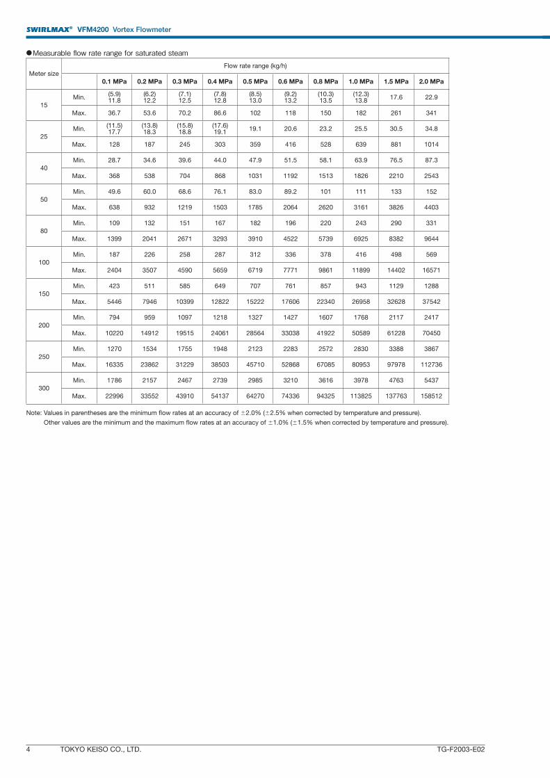
● Measurable fl ow rate range for saturated steam
Meter size
Flow rate range (kg/h)
0.1 MPa 0.2 MPa 0.3 MPa 0.4 MPa 0.5 MPa 0.6 MPa 0.8 MPa 1.0 MPa 1.5 MPa 2.0 MPa
15
Min.(5.9)11.8
(6.2)12.2
(7.1)12.5
(7.8)12.8
(8.5)13.0
(9.2)13.2
(10.3)13.5
(12.3)13.8
17.6 22.9
Max. 36.7 53.6 70.2 86.6 102 118 150 182 261 341
25
Min.(11.5)17.7
(13.8)18.3
(15.8)18.8
(17.6)19.1
19.1 20.6 23.2 25.5 30.5 34.8
Max. 128 187 245 303 359 416 528 639 881 1014
40
Min. 28.7 34.6 39.6 44.0 47.9 51.5 58.1 63.9 76.5 87.3
Max. 368 538 704 868 1031 1192 1513 1826 2210 2543
50
Min. 49.6 60.0 68.6 76.1 83.0 89.2 101 111 133 152
Max. 638 932 1219 1503 1785 2064 2620 3161 3826 4403
80
Min. 109 132 151 167 182 196 220 243 290 331
Max. 1399 2041 2671 3293 3910 4522 5739 6925 8382 9644
100
Min. 187 226 258 287 312 336 378 416 498 569
Max. 2404 3507 4590 5659 6719 7771 9861 11899 14402 16571
150
Min. 423 511 585 649 707 761 857 943 1129 1288
Max. 5446 7946 10399 12822 15222 17606 22340 26958 32628 37542
200
Min. 794 959 1097 1218 1327 1427 1607 1768 2117 2417
Max. 10220 14912 19515 24061 28564 33038 41922 50589 61228 70450
250
Min. 1270 1534 1755 1948 2123 2283 2572 2830 3388 3867
Max. 16335 23862 31229 38503 45710 52868 67085 80953 97978 112736
300
Min. 1786 2157 2467 2739 2985 3210 3616 3978 4763 5437
Max. 22996 33552 43910 54137 64270 74336 94325 113825 137763 158512
Note: Values in parentheses are the minimum flow rates at an accuracy of ±2.0% (±2.5% when corrected by temperature and pressure).
Other values are the minimum and the maximum flow rates at an accuracy of ±1.0% (±1.5% when corrected by temperature and pressure).
SWIRLMAX® VFM4200 Vortex Flowmeter
TOKYO KEISO CO., LTD. 5TG-F2003-E02
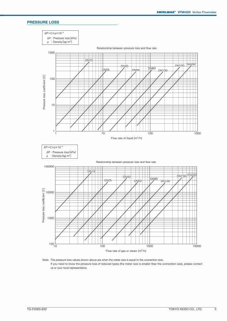
PRESSURE LOSS
Relationship between pressure loss and flow rate1000
100
10
11 10 100 1000
Flow rate of liquid [m3/h]
Pressure loss coefficient [C]
DN15
DN25DN40
DN50DN80
DN100
DN150 DN200
ΔP=C×ρ×10-4
ΔP : Pressure loss[kPa] ρ : Density[kg/m3]
Relationship between pressure loss and flow rate
100
1000
10000
100000
10 100 1000 10000
Flow rate of gas or steam [m3/h]
Pressure loss coefficient [C]
DN15
DN100
DN200DN150DN80
DN50DN40
DN25
ΔP=C×ρ×10-4
ΔP : Pressure loss[kPa] ρ : Density[kg/m3]
Note: The pressure loss values shown above are when the meter size is equal to the connection size.
If you need to know the pressure loss of reduced types (the meter size is smaller than the connection size), please contact
us or your local representative.
SWIRLMAX® VFM4200 Vortex Flowmeter
6 TOKYO KEISO CO., LTD. TG-F2003-E02
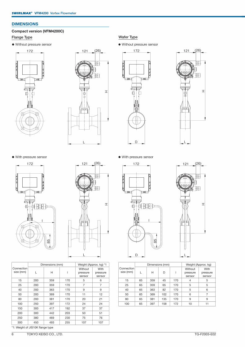
DIMENSIONS
Compact version (VFM4200C)
Flange Type Wafer Type
Connection
size (mm)
Dimensions (mm) Weight (Approx. kg)
L H D l
Without
pressure
sensor
With
pressure
sensor
15 65 359 45 170 4 5
25 65 359 65 170 5 5
40 65 363 82 170 5 6
50 65 369 102 170 6 7
80 65 381 135 170 9 9
100 65 397 158 172 10 11
Connection
size (mm)
Dimensions (mm) Weight (Approx. kg) *1
L H l
Without
pressure
sensor
With
pressure
sensor
15 200 359 170 5 6
25 200 359 170 7 7
40 200 363 170 9 9
50 200 369 170 11 12
80 200 381 170 20 21
100 250 397 172 24 24
150 300 417 192 37 37
200 300 442 203 50 51
250 380 469 230 75 76
300 450 493 255 107 107
*1: Weight of JIS10K flange type
● Without pressure sensor
● With pressure sensor
● Without pressure sensor
● With pressure sensor
172
L
H
121 (26) 172 121 (26)
H
D L
I
85
172 121 (26)
L
H
I
85
172 121 (26)
H
D L
SWIRLMAX® VFM4200 Vortex Flowmeter
TOKYO KEISO CO., LTD. 7TG-F2003-E02
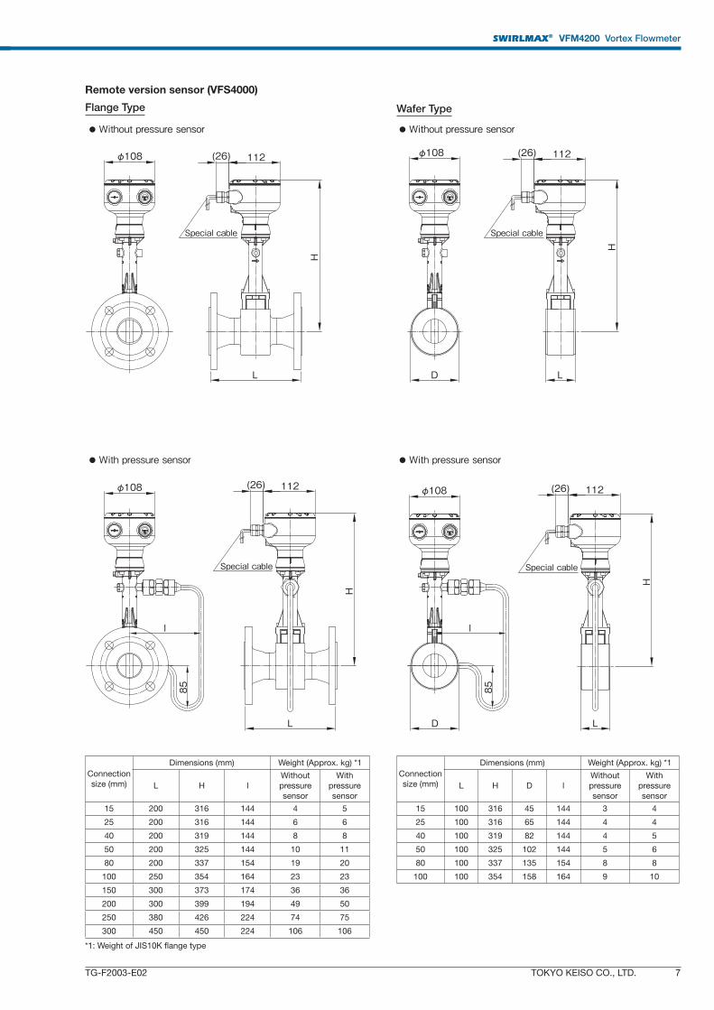
Remote version sensor (VFS4000)
Flange Type Wafer Type
Connection
size (mm)
Dimensions (mm) Weight (Approx. kg) *1
L H D l
Without
pressure
sensor
With
pressure
sensor
15 100 316 45 144 3 4
25 100 316 65 144 4 4
40 100 319 82 144 4 5
50 100 325 102 144 5 6
80 100 337 135 154 8 8
100 100 354 158 164 9 10
Connection
size (mm)
Dimensions (mm) Weight (Approx. kg) *1
L H l
Without
pressure
sensor
With
pressure
sensor
15 200 316 144 4 5
25 200 316 144 6 6
40 200 319 144 8 8
50 200 325 144 10 11
80 200 337 154 19 20
100 250 354 164 23 23
150 300 373 174 36 36
200 300 399 194 49 50
250 380 426 224 74 75
300 450 450 224 106 106
*1: Weight of JIS10K flange type
● Without pressure sensor
● With pressure sensor
● Without pressure sensor
● With pressure sensor
Special cable
Special cableSpecial cable
Special cable
H
D
φ108 (26) 11285
l
H
D L
φ108 (26) 112φ108 (26) 112
L
φ108 (26) 112
l
85
L
L
H
H
SWIRLMAX® VFM4200 Vortex Flowmeter
8 TOKYO KEISO CO., LTD. TG-F2003-E02
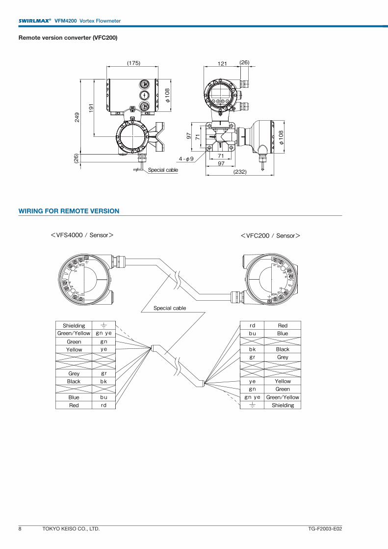
Remote version converter (VFC200)
WIRING FOR REMOTE VERSION
(175)
φ108
249 191
(26)
Special cable
φ108
121 (26)
97 71
7197
(232)
4 -φ9
RedBlue
BlackGrey
YellowGreen
rdbu
b kg r
yegngn ye
rdbu
b kg r
yegngn ye
RedBlue
BlackGrey
YellowGreen
rdbu
bk
gr
yegngnye rd bu
bkgr
yegn
gnye
<VFS4000 / Sensor>
ShieldingGreen/Yellow
Green/YellowShielding
<VFC200 / Sensor>
Special cable
SWIRLMAX® VFM4200 Vortex Flowmeter
TOKYO KEISO CO., LTD. 9TG-F2003-E02
MOUNTING DIRECTION OF CONVERTER AND DISPLAY (For compact version)
● Without pressure sensor ● With pressure sensor
Version A (standard) Version B
Version C Version D
* The arrow indicates the flow direction.* Note that the pressure sensor is on the opposite side of the display in versions B and D.
WIRING STANDARD ACCESSORIES
● Centering ring: 2 (only for wafer type)
● Magnet for setting data: 1
● Tool for removing the converter cover
● Tool for dismounting the display
● Setting data sheet: 1
● Instruction manual: 1
OPTIONS
● G1/2 watertight glands for cable entry: 1 set [symbol: WG]
● No presetting of converter data (parameters) [symbol: NS]
The fl owmeter is delivered with the standard setting.
Please set a fl ow rate range and other data necessary for opera-
tion.
ORDERING INSTRUCTIONS
1. Model and specifi cation code
Example:
Model: VFM4200
Spec code: VG164A2MM20001012010000000000
2. Full-scale fl ow rate (unnecessary when the option NS is specifi ed)
3. Mounting direction of the converter and the display (version A, B,
C, or D: Refer to the top of this page.)
4. Options (Specify if necessary.)
Specify the symbol with reference to [OPTIONS].
5. Name, temperature, pressure, density, and viscosity of measured
fl uid
● Install safety barriers when the VFM4200 is used as an intrinsi-cally safe apparatus.
● Observe the requirements of the safety barrier.● When an isolation barrier is used, ensure that the power supply meets the requirements of the barrier.
Current output (2-wire, 4‒20 mA)Powersupply
C1C2
I1
I2
M1M3
M2/4
+ -
+
-+
-+
Receiver
● Power supply and current output
-+
Power supply and current output (24 V DC)
Contact output
(4‒20 mA)
Safetybarrier
Non-hazardous area
Receiver
C1C2
I1
I2
M1M3
M2/4
+ -
+
-+
-+
● When used as an intrinsically safe apparatus
Safetybarrier
-
+Open collector output or NAMUR output
Open collector output: M1 (+), M2/4 (-)[Load rating: Max. 36 V DC, 100 mA]NAMUR output: M3 (+), M2/4 (-)
Powersupply
Current output (2-wire, 4‒20 mA)
Receiver
C1C2
I1
I2
M1M3
M2/4
+ -
+
-+
-+
● Pulse output, frequency output, status output, or alarm output
* The arrow indicates the flow direction.
Version C Version D
Version A (standard) Version B
SWIRLMAX® VFM4200 Vortex Flowmeter
10 TOKYO KEISO CO., LTD. TG-F2003-E02
MODEL CODE Model: VFM4200 (fl ange type)
Specification code VG164 A 1 1 10000000000 Description StandardFixed code A Always 1 ○
Connection size
2 15 mm / 1/2″ ○
4 25 mm / 1″ ○
6 40 mm / 1-1/2″ ○
7 50 mm / 2″ ○
A 80 mm / 3″ ○
B 100 mm / 4″ ○
D 150 mm / 6″ ○
E 200 mm / 8″ ○
F 250 mm / 10″ ○
G 300 mm / 12″ ○
Flange
A ASME class 150
B ASME class 300
D ASME class 600
M JIS 10K ○
N JIS 20K
TypeA ASME flange
M JIS flange ○
Meter size
2 15 mm / 1/2″
Reduce type:Sizes up to two steps smaller than the connection size can be selected.
○
4 25 mm / 1″ ○
6 40 mm / 1-1/2″ ○
7 50 mm / 2″ ○
A 80 mm / 3″ ○
B 100 mm / 4″ ○
D 150 mm / 6″ ○
E 200 mm / 8″ ○
F 250 mm / 10″ ○
G 300 mm / 12″ ○
Pressure sensor
0 None ○
1 Pressure sensor Max. 0.1 MPa
2 Pressure sensor Max. 0.2 MPa
3 Pressure sensor Max. 0.4 MPa
4 Pressure sensor Max. 0.6 MPa
5 Pressure sensor Max. 1 MPa
6 Pressure sensor Max. 1.6 MPa
7 Pressure sensor Max. 2.5 MPa
8 Pressure sensor Max. 4 MPa
A Pressure sensor Max. 6 MPa
B Pressure sensor Max. 10 MPa
C Pressure sensor with valve Max. 0.1 MPa
D Pressure sensor with valve Max. 0.2 MPa
E Pressure sensor with valve Max. 0.4 MPa
F Pressure sensor with valve Max. 0.6 MPa
G Pressure sensor with valve Max. 1 MPa
H Pressure sensor with valve Max. 1.6 MPa
K Pressure sensor with valve Max. 2.5 MPa
L Pressure sensor with valve Max. 4 MPa
M Pressure sensor with valve Max. 6 MPa
N Pressure sensor with valve Max. 10 MPa
Gasket for Pressure sensor
0 None ○
1 FPM *2 ○
2 FFKM *3
Explosionproof specifications
0 Standard (non-ex) ○
1 ATEX (intrinsically safe)
2 ATEX (flameproof)
5 IECEx (intrinsically safe)
6 IECEx (flameproof)
Y JPN Ex (flameproof)
Housing material 1 Aluminum alloy ○
Type
0 Compact type ○
1 Remote type / Cable length 5 m
2 Remote type / Cable length 10 m
3 Remote type / Cable length 15 m
4 Remote type / Cable length 20 m
5 Remote type / Cable length 25 m
6 Remote type / Cable length 30 m
7 Remote type / Cable length 35 m
8 Remote type / Cable length 40 m
A Remote type / Cable length 45 m
B Remote type / Cable length 50 m
Display 1 LCD ○
Cable entry
2 2 × M20 (with watertight cable gland) ○
8 2 × M20 (with metal cable gland / only for flameproof type)
K 2 × 1/2″ NPT female adapter
N 2 × G1/2 female adapter
Version0
For Gas and Liquid without correction.
For Saturated steam with temperature correction.○
2 For Gas and Superheated steam with temperature and pressure correction. *4
Fixed code 10000000000 Always 10000000000 ○
Special specificationBlank Without ○
/ Z With special request *5*1 JIS20K fl anges are used as standard in common with JIS10K fl anges for both connection sizes between 15 mm and 40 mm.*2 Fluorocarbon rubber*3 Perfl uoroelastomer*4 Selectable if with pressure sensor.*5 Special requirements not included in the above coding system should be designated by adding “/Z” at the end of the code. Please describe the content separately.
SWIRLMAX® VFM4200 Vortex Flowmeter
TOKYO KEISO CO., LTD. 11TG-F2003-E02
Model: VFM4200 (wafer type)
Specification code VG164 A 0 1 1 10000000000 Description Standard
Fixed code A Always 1 ○
Connection size
2 15 mm / 1/2″ ○
4 25 mm / 1″ ○
6 40 mm / 1-1/2″ ○
7 50 mm / 2″ ○
A 80 mm / 3″ ○
B 100 mm / 4″ ○
Flange
A ASME class 150
B ASME class 300
D ASME class 600
M JIS 10K ○
N JIS 20K
Type 0 Wafer type ○
Meter size
2 15 mm / 1/2″Reduce type:
The same size as the
connection size can be
selected.
○
4 25 mm / 1″ ○
6 40 mm / 1-1/2″ ○
7 50 mm / 2″ ○
A 80 mm / 3″ ○
B 100 mm / 4″ ○
Pressure sensor
0 None ○
1 Pressure sensor Max. 0.1 MPa
2 Pressure sensor Max. 0.2 MPa
3 Pressure sensor Max. 0.4 MPa
4 Pressure sensor Max. 0.6 MPa
5 Pressure sensor Max. 1 MPa
6 Pressure sensor Max. 1.6 MPa
7 Pressure sensor Max. 2.5 MPa
8 Pressure sensor Max. 4 MPa
A Pressure sensor Max. 6 MPa
B Pressure sensor Max. 10 MPa
C Pressure sensor with valve Max. 0.1 MPa
D Pressure sensor with valve Max. 0.2 MPa
E Pressure sensor with valve Max. 0.4 MPa
F Pressure sensor with valve Max. 0.6 MPa
G Pressure sensor with valve Max. 1 MPa
H Pressure sensor with valve Max. 1.6 MPa
K Pressure sensor with valve Max. 2.5 MPa
L Pressure sensor with valve Max. 4 MPa
M Pressure sensor with valve Max. 6 MPa
N Pressure sensor with valve Max. 10 MPa
Gasket for Pressure sensor
0 None ○
1 FPM *1 ○
2 FFKM *2
Explosionproof specifications
0 Standard (non-ex) ○
1 ATEX (intrinsically safe)
2 ATEX (flameproof)
5 IECEx (intrinsically safe)
6 IECEx (flameproof)
Y JPN Ex (flameproof)
Housing material 1 Aluminum alloy ○
Type
0 Compact type ○
1 Remote type / Cable length 5 m
2 Remote type / Cable length 10 m
3 Remote type / Cable length 15 m
4 Remote type / Cable length 20 m
5 Remote type / Cable length 25 m
6 Remote type / Cable length 30 m
7 Remote type / Cable length 35 m
8 Remote type / Cable length 40 m
A Remote type / Cable length 45 m
B Remote type / Cable length 50 m
Display 1 LCD ○
Cable entry
2 2 × M20 (with watertight cable gland) ○
8 2 × M20 (with metal cable gland / only for flameproof type)
K 2 × 1/2″ NPT female adapter
N 2 × G1/2 female adapter
Version0
For Gas and Liquid without correction.For Saturated steam with temperature correction.
○
2 For Gas and Superheated steam with temperature and pressure correction. *3
Fixed code 10000000000 Always 10000000000 ○
Special specificationBlank Without ○
/ Z With special request *4
*1 Fluorocarbon rubber
*2 Perfl uoroelastomer
*3 Selectable if with pressure sensor.*4 Special requirements not included in the above coding system should be designated by adding “/Z” at the end of the code. Please describe the content separately.
SWIRLMAX® VFM4200 Vortex Flowmeter
12 TOKYO KEISO CO., LTD. TG-F2003-E02
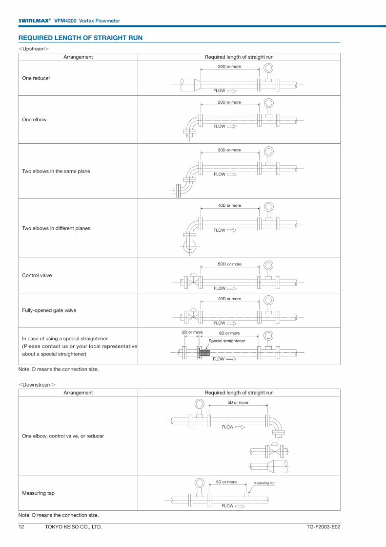
REQUIRED LENGTH OF STRAIGHT RUN
<Upstream>
Arrangement Required length of straight run
One reducer
One elbow
Two elbows in the same plane
Two elbows in different planes
Control valve
Fully-opened gate valve
In case of using a special straightener
(Please contact us or your local representative
about a special straightener)
Note: D means the connection size.
<Downstream>
Arrangement Required length of straight run
One elbow, control valve, or reducer
Measuring tap
Note: D means the connection size.
FLOW
5D or more Measuring tap
FLOW
5D or more
FLOW
20D or more
FLOW
50D or more
FLOW
40D or more
FLOW
30D or more
FLOW
20D or more
FLOW
20D or more
FLOW
Special straightener
8D or more2D or more
SWIRLMAX® VFM4200 Vortex Flowmeter
TOKYO KEISO CO., LTD. 13TG-F2003-E02
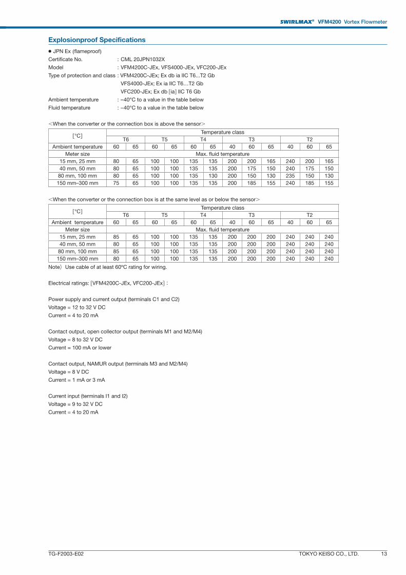
Explosionproof Specifications
● JPN Ex (fl ameproof)Certifi cate No. : CML 20JPN1032X
Model : VFM4200C-JEx, VFS4000-JEx, VFC200-JEx
Type of protection and class : VFM4200C-JEx; Ex db ia IIC T6...T2 Gb
VFS4000-JEx; Ex ia IIC T6…T2 Gb
VFC200-JEx; Ex db [ia] IIC T6 Gb
Ambient temperature : –40°C to a value in the table below
Fluid temperature : –40°C to a value in the table below
<When the converter or the connection box is above the sensor>
[°C]Temperature class
T6 T5 T4 T3 T2
Ambient temperature 60 65 60 65 60 65 40 60 65 40 60 65
Meter size Max. fluid temperature
15 mm, 25 mm 80 65 100 100 135 135 200 200 165 240 200 165
40 mm, 50 mm 80 65 100 100 135 135 200 175 150 240 175 150
80 mm, 100 mm 80 65 100 100 135 130 200 150 130 235 150 130
150 mm–300 mm 75 65 100 100 135 135 200 185 155 240 185 155
<When the converter or the connection box is at the same level as or below the sensor>
[°C]Temperature class
T6 T5 T4 T3 T2
Ambient temperature 60 65 60 65 60 65 40 60 65 40 60 65
Meter size Max. fluid temperature
15 mm, 25 mm 85 65 100 100 135 135 200 200 200 240 240 240
40 mm, 50 mm 80 65 100 100 135 135 200 200 200 240 240 240
80 mm, 100 mm 85 65 100 100 135 135 200 200 200 240 240 240
150 mm–300 mm 80 65 100 100 135 135 200 200 200 240 240 240
Note)Use cable of at least 60ºC rating for wiring.
Electrical ratings: [VFM4200C-JEx, VFC200-JEx]:
Power supply and current output (terminals C1 and C2)
Voltage = 12 to 32 V DC
Current = 4 to 20 mA
Contact output, open collector output (terminals M1 and M2/M4)
Voltage = 8 to 32 V DC
Current = 100 mA or lower
Contact output, NAMUR output (terminals M3 and M2/M4)
Voltage = 8 V DC
Current = 1 mA or 3 mA
Current input (terminals I1 and I2)
Voltage = 9 to 32 V DC
Current = 4 to 20 mA
SWIRLMAX® VFM4200 Vortex Flowmeter
14 TOKYO KEISO CO., LTD. TG-F2003-E02
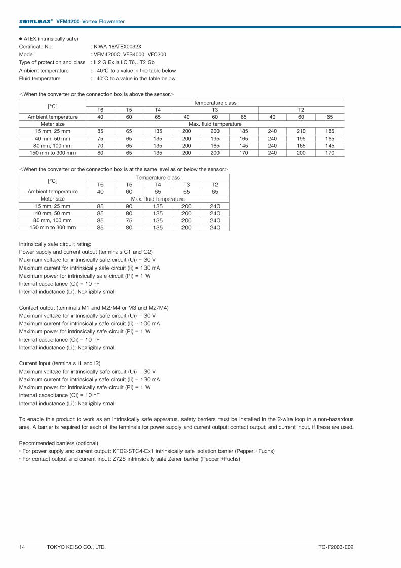
● ATEX (intrinsically safe)
Certifi cate No. : KIWA 18ATEX0032X
Model : VFM4200C, VFS4000, VFC200
Type of protection and class : II 2 G Ex ia IIC T6…T2 Gb
Ambient temperature : −40ºC to a value in the table below
Fluid temperature : −40ºC to a value in the table below
<When the converter or the connection box is above the sensor>
[°C]Temperature class
T6 T5 T4 T3 T2
Ambient temperature 40 60 65 40 60 65 40 60 65
Meter size Max. fluid temperature
15 mm, 25 mm 85 65 135 200 200 185 240 210 185
40 mm, 50 mm 75 65 135 200 195 165 240 195 165
80 mm, 100 mm 70 65 135 200 165 145 240 165 145
150 mm to 300 mm 80 65 135 200 200 170 240 200 170
<When the converter or the connection box is at the same level as or below the sensor>
[°C] Temperature classT6 T5 T4 T3 T2
Ambient temperature 40 60 65 65 65Meter size Max. fl uid temperature
15 mm, 25 mm 85 90 135 200 24040 mm, 50 mm 85 80 135 200 24080 mm, 100 mm 85 75 135 200 240
150 mm to 300 mm 85 80 135 200 240
Intrinsically safe circuit rating:Power supply and current output (terminals C1 and C2)Maximum voltage for intrinsically safe circuit (Ui) = 30 VMaximum current for intrinsically safe circuit (Ii) = 130 mAMaximum power for intrinsically safe circuit (Pi) = 1 WInternal capacitance (Ci) = 10 nFInternal inductance (Li): Negligibly small
Contact output (terminals M1 and M2/M4 or M3 and M2/M4)Maximum voltage for intrinsically safe circuit (Ui) = 30 VMaximum current for intrinsically safe circuit (Ii) = 100 mAMaximum power for intrinsically safe circuit (Pi) = 1 WInternal capacitance (Ci) = 10 nFInternal inductance (Li): Negligibly small
Current input (terminals I1 and I2)Maximum voltage for intrinsically safe circuit (Ui) = 30 VMaximum current for intrinsically safe circuit (Ii) = 130 mAMaximum power for intrinsically safe circuit (Pi) = 1 WInternal capacitance (Ci) = 10 nFInternal inductance (Li): Negligibly small
To enable this product to work as an intrinsically safe apparatus, safety barriers must be installed in the 2-wire loop in a non-hazardous area. A barrier is required for each of the terminals for power supply and current output; contact output; and current input, if these are used.
Recommended barriers (optional)• For power supply and current output: KFD2-STC4-Ex1 intrinsically safe isolation barrier (Pepperl+Fuchs)• For contact output and current input: Z728 intrinsically safe Zener barrier (Pepperl+Fuchs)
SWIRLMAX® VFM4200 Vortex Flowmeter
TOKYO KEISO CO., LTD. 15TG-F2003-E02
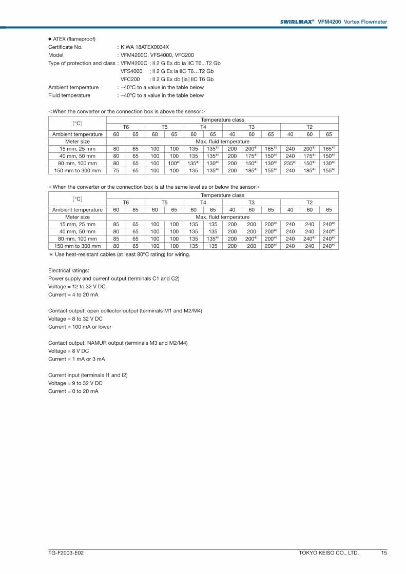
● ATEX (flameproof)
Certifi cate No. : KIWA 18ATEX0034X
Model : VFM4200C, VFS4000, VFC200
Type of protection and class : VFM4200C ; II 2 G Ex db ia IIC T6...T2 Gb
VFS4000 ; II 2 G Ex ia IIC T6…T2 Gb
VFC200 ; II 2 G Ex db [ia] IIC T6 Gb
Ambient temperature : −40ºC to a value in the table below
Fluid temperature : −40ºC to a value in the table below
<When the converter or the connection box is above the sensor>
[°C]Temperature class
T6 T5 T4 T3 T2
Ambient temperature 60 65 60 65 60 65 40 60 65 40 60 65
Meter size Max. fluid temperature
15 mm, 25 mm 80 65 100 100 135 135✽) 200 200✽) 165✽) 240 200✽) 165✽)
40 mm, 50 mm 80 65 100 100 135 135✽) 200 175✽) 150✽) 240 175✽) 150✽)
80 mm, 100 mm 80 65 100 100✽) 135✽) 130✽) 200 150✽) 130✽) 235✽) 150✽) 130✽)
150 mm to 300 mm 75 65 100 100 135 135✽) 200 185✽) 155✽) 240 185✽) 155✽)
<When the converter or the connection box is at the same level as or below the sensor>
[°C]Temperature class
T6 T5 T4 T3 T2
Ambient temperature 60 65 60 65 60 65 40 60 65 40 60 65
Meter size Max. fluid temperature
15 mm, 25 mm 85 65 100 100 135 135 200 200 200✽) 240 240 240✽)
40 mm, 50 mm 80 65 100 100 135 135 200 200 200✽) 240 240 240✽)
80 mm, 100 mm 85 65 100 100 135 135✽) 200 200✽) 200✽) 240 240✽) 240✽)
150 mm to 300 mm 80 65 100 100 135 135 200 200 200✽) 240 240 240✽)
* Use heat-resistant cables (at least 80ºC rating) for wiring.
Electrical ratings:
Power supply and current output (terminals C1 and C2)
Voltage = 12 to 32 V DC
Current = 4 to 20 mA
Contact output, open collector output (terminals M1 and M2/M4)
Voltage = 8 to 32 V DC
Current = 100 mA or lower
Contact output, NAMUR output (terminals M3 and M2/M4)
Voltage = 8 V DC
Current = 1 mA or 3 mA
Current input (terminals I1 and I2)
Voltage = 9 to 32 V DC
Current = 0 to 20 mA
SWIRLMAX® VFM4200 Vortex Flowmeter
16 TOKYO KEISO CO., LTD. TG-F2003-E02
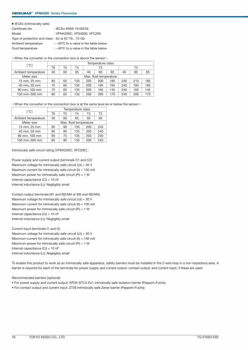
● IECEx (intrinsically safe)
Certifi cate No. : IECEx KIWA 19.0023X
Model : VFM4200C, VFS4000, VFC200
Type of protection and class : Ex ia IIC T6…T2 Gb
Ambient temperature : −40ºC to a value in the table below
Fluid temperature : −40ºC to a value in the table below
<When the converter or the connection box is above the sensor>
[°C]Temperature class
T6 T5 T4 T3 T2
Ambient temperature 40 60 65 40 60 65 40 60 65
Meter size Max. fluid temperature
15 mm, 25 mm 85 65 135 200 200 185 240 210 185
40 mm, 50 mm 75 65 135 200 195 165 240 195 165
80 mm, 100 mm 70 65 135 200 165 145 240 165 145
150 mm–300 mm 80 65 135 200 200 170 240 200 170
<When the converter or the connection box is at the same level as or below the sensor>
[°C]Temperature class
T6 T5 T4 T3 T2
Ambient temperature 40 60 65 65 65
Meter size Max. fluid temperature
15 mm, 25 mm 85 90 135 200 240
40 mm, 50 mm 85 80 135 200 240
80 mm, 100 mm 85 75 135 200 240
150 mm–300 mm 85 80 135 200 240
Intrinsically safe circuit rating [VFM4200C, VFC200] :
Power supply and current output (terminals C1 and C2)
Maximum voltage for intrinsically safe circuit (Ui) = 30 V
Maximum current for intrinsically safe circuit (Ii) = 130 mA
Maximum power for intrinsically safe circuit (Pi) = 1 W
Internal capacitance (Ci) = 10 nF
Internal inductance (Li): Negligibly small
Contact output (terminals M1 and M2/M4 or M3 and M2/M4)
Maximum voltage for intrinsically safe circuit (Ui) = 30 V
Maximum current for intrinsically safe circuit (Ii) = 100 mA
Maximum power for intrinsically safe circuit (Pi) = 1 W
Internal capacitance (Ci) = 10 nF
Internal inductance (Li): Negligibly small
Current input (terminals I1 and I2)
Maximum voltage for intrinsically safe circuit (Ui) = 30 V
Maximum current for intrinsically safe circuit (Ii) = 130 mA
Maximum power for intrinsically safe circuit (Pi) = 1 W
Internal capacitance (Ci) = 10 nF
Internal inductance (Li): Negligibly small
To enable this product to work as an intrinsically safe apparatus, safety barriers must be installed in the 2-wire loop in a non-hazardous area. A
barrier is required for each of the terminals for power supply and current output; contact output; and current input, if these are used.
Recommended barriers (optional)
• For power supply and current output: KFD2-STC4-Ex1 intrinsically safe isolation barrier (Pepperl+Fuchs)
• For contact output and current input: Z728 intrinsically safe Zener barrier (Pepperl+Fuchs)
SWIRLMAX® VFM4200 Vortex Flowmeter
TOKYO KEISO CO., LTD. 17TG-F2003-E02
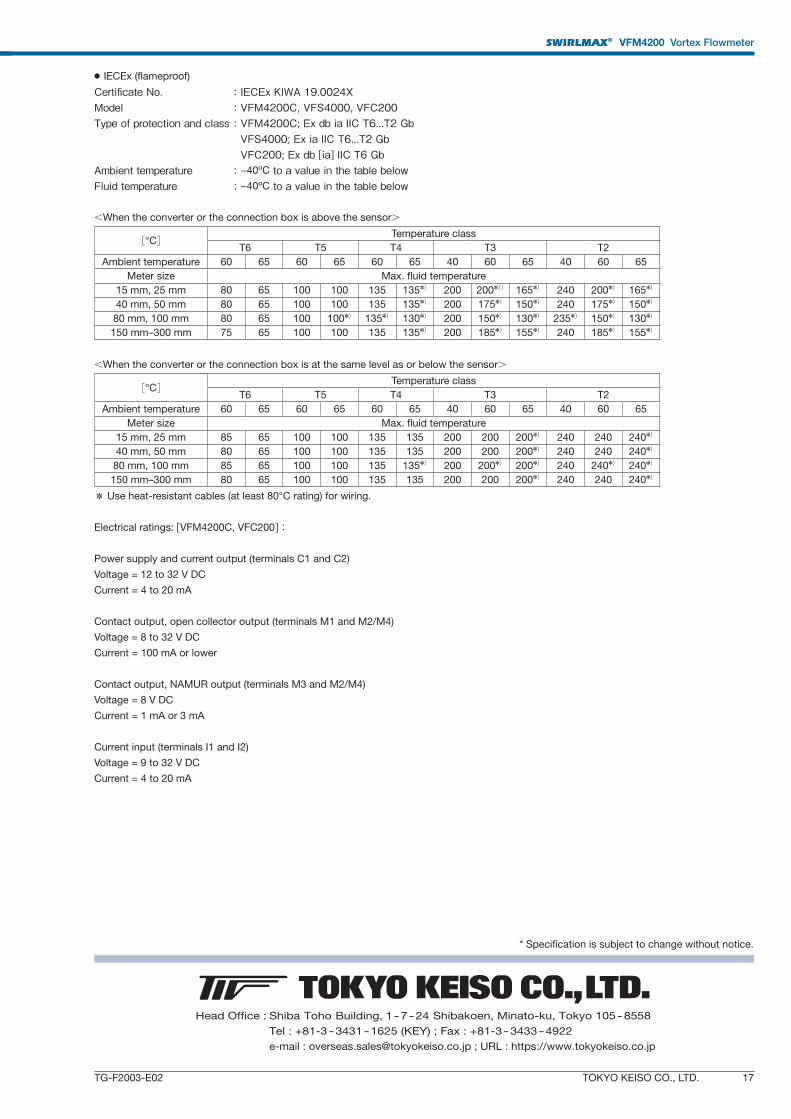
● IECEx (fl ameproof)
Certifi cate No. : IECEx KIWA 19.0024XModel : VFM4200C, VFS4000, VFC200Type of protection and class : VFM4200C; Ex db ia IIC T6...T2 Gb VFS4000; Ex ia IIC T6...T2 Gb VFC200; Ex db [ia] IIC T6 GbAmbient temperature : −40ºC to a value in the table belowFluid temperature : −40ºC to a value in the table below
<When the converter or the connection box is above the sensor>
[°C]Temperature class
T6 T5 T4 T3 T2
Ambient temperature 60 65 60 65 60 65 40 60 65 40 60 65
Meter size Max. fluid temperature
15 mm, 25 mm 80 65 100 100 135 135✽) 200 200✽)) 165✽) 240 200✽) 165✽)
40 mm, 50 mm 80 65 100 100 135 135✽) 200 175✽) 150✽) 240 175✽) 150✽)
80 mm, 100 mm 80 65 100 100✽) 135✽) 130✽) 200 150✽) 130✽) 235✽) 150✽) 130✽)
150 mm–300 mm 75 65 100 100 135 135✽) 200 185✽) 155✽) 240 185✽) 155✽)
<When the converter or the connection box is at the same level as or below the sensor>
[°C]Temperature class
T6 T5 T4 T3 T2
Ambient temperature 60 65 60 65 60 65 40 60 65 40 60 65
Meter size Max. fluid temperature
15 mm, 25 mm 85 65 100 100 135 135 200 200 200✽) 240 240 240✽)
40 mm, 50 mm 80 65 100 100 135 135 200 200 200✽) 240 240 240✽)
80 mm, 100 mm 85 65 100 100 135 135✽) 200 200✽) 200✽) 240 240✽) 240✽)
150 mm–300 mm 80 65 100 100 135 135 200 200 200✽) 240 240 240✽)
* Use heat-resistant cables (at least 80°C rating) for wiring.
Electrical ratings: [VFM4200C, VFC200]:
Power supply and current output (terminals C1 and C2)
Voltage = 12 to 32 V DC
Current = 4 to 20 mA
Contact output, open collector output (terminals M1 and M2/M4)
Voltage = 8 to 32 V DC
Current = 100 mA or lower
Contact output, NAMUR output (terminals M3 and M2/M4)
Voltage = 8 V DC
Current = 1 mA or 3 mA
Current input (terminals I1 and I2)
Voltage = 9 to 32 V DC
Current = 4 to 20 mA
Head Office : Shiba Toho Building, 1 – 7 – 24 Shibakoen, Minato-ku, Tokyo 105 – 8558
Tel : +81-3 – 3431 – 1625 (KEY) ; Fax : +81-3 – 3433 – 4922
e-mail : [email protected] ; URL : https://www.tokyokeiso.co.jp
* Specification is subject to change without notice.


![会期 会場 ]東京ビッグサイト[ 会期 ]2020年11月11 日 水~13日金[ 会場 ]東京ビッグサイト レンタル備品 のご案内 スマート装飾プラン](https://img.pdfslide.tips/doc/110x75/5f223de7174d1b119a5cf70a/oe-ffff-oe-202011oe11-i13e.jpg)