Embed Size (px)
Citation preview

Expert Documentation
System Variables
For KUKA System Software 8.1, 8.2 and 8.3
KUKA Roboter GmbH
Issued: 16.08.2012
Version: KSS 8.1, 8.2, 8.3 Systemvariablen V2 en (PDF)

System Variables
2 / 131 Issued: 16.08.2012 Version: KSS 8.1, 8.2, 8.3 Systemvariablen V2 en (PDF)
© Copyright 2012
KUKA Roboter GmbH
Zugspitzstraße 140
D-86165 Augsburg
Germany
This documentation or excerpts therefrom may not be reproduced or disclosed to third parties without the express permission of KUKA Roboter GmbH.
Other functions not described in this documentation may be operable in the controller. The user has no claims to these functions, however, in the case of a replacement or service work.
We have checked the content of this documentation for conformity with the hardware and software described. Nevertheless, discrepancies cannot be precluded, for which reason we are not able to guarantee total conformity. The information in this documentation is checked on a regular basis, how-ever, and necessary corrections will be incorporated in the subsequent edition.
Subject to technical alterations without an effect on the function.
Translation of the original documentation
KIM-PS5-DOC
Publication: Pub KSS 8.1, 8.2, 8.3 Systemvariablen (PDF) en
Bookstructure: KSS 8.1, 8.2, 8.3 Systemvariablen V1.1
Version: KSS 8.1, 8.2, 8.3 Systemvariablen V2 en (PDF)

Contents
Contents
1 Introduction .................................................................................................. 9
1.1 Target group .............................................................................................................. 9
1.2 Industrial robot documentation ................................................................................... 9
1.3 Representation of warnings and notes ...................................................................... 9
1.4 Terms used ................................................................................................................ 10
2 Safety ............................................................................................................ 11
3 System variables ......................................................................................... 13
3.1 $ABS_ACCUR ........................................................................................................... 13
3.2 $ABS_RELOAD ......................................................................................................... 13
3.3 $ABS_UPDATE ......................................................................................................... 13
3.4 $ACC ......................................................................................................................... 14
3.5 $ACC_C ..................................................................................................................... 14
3.6 $ACC_AXIS ............................................................................................................... 14
3.7 $ACC_AXIS_C ........................................................................................................... 15
3.8 $ACC_CAR_ACT ....................................................................................................... 15
3.9 $ACC_CAR_MAX ...................................................................................................... 16
3.10 $ACC_EXTAX ............................................................................................................ 16
3.11 $ACC_EXTAX_C ....................................................................................................... 16
3.12 $ACCU_STATE ......................................................................................................... 17
3.13 $ACT_ADVANCE ...................................................................................................... 17
3.14 $ADVANCE ................................................................................................................ 18
3.15 $ACT_EX_AX ............................................................................................................ 18
3.16 $ACT_BASE .............................................................................................................. 18
3.17 $ACT_BASE_C .......................................................................................................... 18
3.18 $ACT_TOOL .............................................................................................................. 19
3.19 $ACT_TOOL_C ......................................................................................................... 19
3.20 $ANIN ........................................................................................................................ 19
3.21 $ANOUT .................................................................................................................... 19
3.22 $APO ......................................................................................................................... 20
3.23 $APO_C ..................................................................................................................... 21
3.24 $ASYNC_AXIS .......................................................................................................... 21
3.25 $ASYNC_EX_AX_DECOUPLE ................................................................................. 22
3.26 $ASYNC_FLT ............................................................................................................ 23
3.27 $ASYNC_STATE ....................................................................................................... 23
3.28 $AXIS_ACT ................................................................................................................ 24
3.29 $AXIS_ACT_MEAS ................................................................................................... 24
3.30 $AXIS_BACK ............................................................................................................. 24
3.31 $AXIS_FOR ............................................................................................................... 25
3.32 $AXIS_INT ................................................................................................................. 26
3.33 $AXIS_MOT ............................................................................................................... 26
3.34 $AXIS_RET ................................................................................................................ 26
3.35 $B_IN ......................................................................................................................... 26
3.36 $B_OUT ..................................................................................................................... 26
3.37 $BASE ....................................................................................................................... 27
3.38 $BASE_C ................................................................................................................... 27
3.39 $BASE_KIN ............................................................................................................... 27
3 / 131Issued: 16.08.2012 Version: KSS 8.1, 8.2, 8.3 Systemvariablen V2 en (PDF)

4 / 131
System Variables
3.40 $BRAKE_SIG ............................................................................................................ 28
3.41 $CAB_FANSPEED .................................................................................................... 28
3.42 $CIRC_MODE ........................................................................................................... 28
3.43 $CIRC_TYPE ............................................................................................................ 31
3.44 $CIRC_TYPE_C ........................................................................................................ 31
3.45 $CMD ........................................................................................................................ 31
3.46 $CURR_ACT ............................................................................................................. 32
3.47 $CYCFLAG ................................................................................................................ 32
3.48 $DATA_EXT_OBJx .................................................................................................. 33
3.49 $DATA_INTEGRITY .................................................................................................. 33
3.50 $DATAPATH ............................................................................................................. 33
3.51 $DATE ....................................................................................................................... 34
3.52 $DEVICE ................................................................................................................... 35
3.53 $DISTANCE .............................................................................................................. 35
3.54 $DIST_NEXT ............................................................................................................. 35
3.55 $DRIVES_ENABLE ................................................................................................... 35
3.56 $ERR ......................................................................................................................... 35
3.57 $EX_AX_IGNORE ..................................................................................................... 37
3.58 $FAST_MEAS_COUNT ............................................................................................ 37
3.59 $FAST_MEAS_COUNT_RESET .............................................................................. 37
3.60 $FAST_MEAS_COUNT_TIME .................................................................................. 37
3.61 $FILTER .................................................................................................................... 38
3.62 $FILTER_C ................................................................................................................ 38
3.63 $FLAG ....................................................................................................................... 38
3.64 $FOL_ERROR ........................................................................................................... 39
3.65 $FCT_CALL ............................................................................................................... 39
3.66 $GEAR_JERK ........................................................................................................... 39
3.67 $GEAR_JERK_C ....................................................................................................... 40
3.68 $HOLDING_TORQUE ............................................................................................... 40
3.69 $HOLDING_TORQUE_MAND .................................................................................. 41
3.70 $HOME ...................................................................................................................... 41
3.71 $IN ............................................................................................................................. 42
3.72 $INPOSITION ............................................................................................................ 42
3.73 $INTERPRETER ....................................................................................................... 42
3.74 $IOBUS_INFO ........................................................................................................... 43
3.75 $IOSIM_IN ................................................................................................................. 43
3.76 $IOSIM_OPT ............................................................................................................. 44
3.76.1 Simulating inputs/outputs – KUKA System Software 8.2 or higher ...................... 45
3.76.2 Simulating inputs/outputs – KUKA System Software 8.1 ..................................... 45
3.77 $IOSIM_OUT ............................................................................................................. 45
3.78 $IOSYS_IN_FALSE ................................................................................................... 46
3.79 $IOSYS_IN_TRUE .................................................................................................... 46
3.80 $IPO_MODE .............................................................................................................. 47
3.81 $IPO_MODE_C ......................................................................................................... 47
3.82 $IPO_WAIT_FOR ...................................................................................................... 47
3.83 $IPO_WAIT_FOR_ON .............................................................................................. 48
3.84 $IPO_WAIT_STATE .................................................................................................. 48
3.85 $IS_OFFICE_LITE .................................................................................................... 48
3.86 $I2T_OL ..................................................................................................................... 48
Issued: 16.08.2012 Version: KSS 8.1, 8.2, 8.3 Systemvariablen V2 en (PDF)

Contents
3.87 $JERK ........................................................................................................................ 49
3.88 $JERK_C ................................................................................................................... 49
3.89 $KCP_CONNECT ...................................................................................................... 50
3.90 $KCP_IP .................................................................................................................... 50
3.91 $KCP_TYPE .............................................................................................................. 50
3.92 $KDO_ACT ................................................................................................................ 50
3.93 $KR_SERIALNO ........................................................................................................ 51
3.94 $LDC_ACTIVE ........................................................................................................... 51
3.95 $LDC_LOADED ......................................................................................................... 51
3.96 $LDC_RESULT .......................................................................................................... 52
3.97 $LK_MASTER ............................................................................................................ 52
3.98 $LK_SLAVES ............................................................................................................ 52
3.99 $LOAD ....................................................................................................................... 53
3.100 $LOAD_C ................................................................................................................... 54
3.101 $LOAD_A1 ................................................................................................................. 55
3.102 $LOAD_A1_C ............................................................................................................ 55
3.103 $LOAD_A2 ................................................................................................................. 56
3.104 $LOAD_A2_C ............................................................................................................ 56
3.105 $LOAD_A3 ................................................................................................................. 57
3.106 $LOAD_A3_C ............................................................................................................ 57
3.107 $MAMES_ACT ........................................................................................................... 58
3.108 $MASTERINGTEST_GROUP ................................................................................... 59
3.109 $MASTERINGTEST_REQ_INT ................................................................................. 59
3.110 $MEAS_PULSE ......................................................................................................... 60
3.111 $MODE_OP ............................................................................................................... 60
3.112 $MOT_STOP ............................................................................................................. 60
3.113 $MOT_TEMP ............................................................................................................. 61
3.114 $MOUSE_ACT ........................................................................................................... 61
3.115 $MOUSE_DOM ......................................................................................................... 61
3.116 $MOUSE_ON ............................................................................................................ 62
3.117 $MOUSE_ROT .......................................................................................................... 62
3.118 $MOUSE_TRA ........................................................................................................... 62
3.119 $MOVE_BCO ............................................................................................................. 62
3.120 $NULLFRAME ........................................................................................................... 62
3.121 $NUM_IN ................................................................................................................... 63
3.122 $NUM_OUT ............................................................................................................... 63
3.123 $ORI_TYPE ............................................................................................................... 63
3.124 $ORI_TYPE_C ........................................................................................................... 64
3.125 $OUT ......................................................................................................................... 64
3.126 $OUT_C ..................................................................................................................... 64
3.127 $OV_ASYNC ............................................................................................................. 65
3.128 $OV_PRO .................................................................................................................. 65
3.129 $OV_ROB .................................................................................................................. 66
3.130 $PAL_MODE ............................................................................................................. 66
3.131 $PATHTIME ............................................................................................................... 66
3.132 $PC_FANSPEED ....................................................................................................... 67
3.133 $PINGCOOPKRC ...................................................................................................... 67
3.134 $POS_ACT ................................................................................................................ 68
3.135 $POS_ACT_MES ...................................................................................................... 68
5 / 131Issued: 16.08.2012 Version: KSS 8.1, 8.2, 8.3 Systemvariablen V2 en (PDF)

6 / 131
System Variables
3.136 $POS_BACK ............................................................................................................. 68
3.137 $POS_FOR ............................................................................................................... 69
3.138 $POS_INT ................................................................................................................. 69
3.139 $POS_RET ................................................................................................................ 70
3.140 $POWER_FAIL ......................................................................................................... 70
3.141 $POWEROFF_DELAYTIME ..................................................................................... 70
3.142 $PRO_IP ................................................................................................................... 70
3.143 $PRO_IP0 ................................................................................................................. 71
3.144 $PRO_IP1 ................................................................................................................. 72
3.145 $PRO_MODE ............................................................................................................ 72
3.146 $PRO_MODE0 .......................................................................................................... 73
3.147 $PRO_MODE1 .......................................................................................................... 73
3.148 $PRO_NAME ............................................................................................................ 74
3.149 $PRO_NAME0 .......................................................................................................... 74
3.150 $PRO_NAME1 .......................................................................................................... 74
3.151 $PRO_STATE ........................................................................................................... 75
3.152 $PRO_STATE0 ......................................................................................................... 75
3.153 $PRO_STATE1 ......................................................................................................... 75
3.154 $RCV_INFO .............................................................................................................. 75
3.155 $RED_VEL ................................................................................................................ 76
3.156 $RED_VEL_C ............................................................................................................ 76
3.157 $REVO_NUM ............................................................................................................ 76
3.158 $RINT_LIST ............................................................................................................... 76
3.159 $ROB_TIMER ............................................................................................................ 77
3.160 $ROBNAME .............................................................................................................. 78
3.161 $ROBROOT_C .......................................................................................................... 78
3.162 $ROBROOT_KIN ...................................................................................................... 78
3.163 $ROBRUNTIME ........................................................................................................ 79
3.164 $ROBTRAFO ............................................................................................................. 79
3.165 $ROTSYS .................................................................................................................. 79
3.166 $ROTSYS_C ............................................................................................................. 79
3.167 $RUNTIME_DATA0 ................................................................................................... 80
3.168 $RUNTIME_DATA1 ................................................................................................... 80
3.169 $RUNTIME_ERROR0 ............................................................................................... 81
3.170 $RUNTIME_ERROR1 ............................................................................................... 81
3.171 $RVM ......................................................................................................................... 81
3.172 $SAFETY_DRIVES_ENABLED ................................................................................ 82
3.173 $SAFETY_SW ........................................................................................................... 82
3.174 $SAFE_FS_STATE ................................................................................................... 83
3.175 $SAFE_IBN ............................................................................................................... 83
3.176 $SAFE_IBN_ALLOWED ............................................................................................ 83
3.177 $SEN_PINT ............................................................................................................... 84
3.178 $SEN_PINT_C .......................................................................................................... 84
3.179 $SEN_PREA ............................................................................................................. 84
3.180 $SEN_PREA_C ......................................................................................................... 85
3.181 $SERVO_SIM ............................................................................................................ 85
3.182 $SET_IO_SIZE .......................................................................................................... 85
3.183 $SINGUL_DIST ......................................................................................................... 86
3.184 $SINT_LIST ............................................................................................................... 86
Issued: 16.08.2012 Version: KSS 8.1, 8.2, 8.3 Systemvariablen V2 en (PDF)

Contents
3.185 $SOFTPLCBOOL ...................................................................................................... 87
3.186 $SOFTPLCINT ........................................................................................................... 87
3.187 $SOFTPLCREAL ....................................................................................................... 88
3.188 $SOFT_PLC_EVENT ................................................................................................ 88
3.189 $SPL_TECH .............................................................................................................. 89
3.190 $SPL_TECH_C .......................................................................................................... 92
3.191 $SPL_TECH_LINK .................................................................................................... 93
3.192 $SPL_TECH_LINK_C ................................................................................................ 94
3.193 $SPL_TSYS ............................................................................................................... 94
3.194 $SPL_VEL_MODE ..................................................................................................... 95
3.195 $SPL_VEL_RESTR ................................................................................................... 95
3.196 $SR_ACTIVETOOL ................................................................................................... 96
3.197 $SSB_ACTIVE ........................................................................................................... 96
3.198 $STOPMB_ID ............................................................................................................ 97
3.199 $STOPNOAPROX ..................................................................................................... 97
3.200 $SUPPRESS_ABS_ACCUR ..................................................................................... 97
3.201 $TECH ....................................................................................................................... 97
3.202 $TECH_C ................................................................................................................... 101
3.203 $TECHANGLE ........................................................................................................... 102
3.204 $TECHANGLE_C ...................................................................................................... 102
3.205 $TECHIN .................................................................................................................... 102
3.206 $TECHPAR ................................................................................................................ 103
3.207 $TECHPAR_C ........................................................................................................... 103
3.208 $TECHSYS ................................................................................................................ 104
3.209 $TECHSYS_C ........................................................................................................... 104
3.210 $TECHVAL ................................................................................................................ 105
3.211 $TIMER ...................................................................................................................... 105
3.212 $TIMER_FLAG .......................................................................................................... 106
3.213 $TIMER_STOP .......................................................................................................... 106
3.214 $TOOL ....................................................................................................................... 106
3.215 $TOOL_C ................................................................................................................... 106
3.216 $TORQ_DIFF ............................................................................................................. 107
3.217 $TORQ_DIFF2 ........................................................................................................... 107
3.218 $TORQMON .............................................................................................................. 107
3.219 $TORQMON_COM .................................................................................................... 108
3.220 $TORQUE_AXIS_ACT .............................................................................................. 108
3.221 $TORQUE_AXIS_LIMITS .......................................................................................... 109
3.222 $TORQUE_AXIS_MAX .............................................................................................. 110
3.223 $TORQUE_AXIS_MAX_0 .......................................................................................... 111
3.224 $TRACE ..................................................................................................................... 111
3.225 $TSYS ....................................................................................................................... 112
3.226 $VEL .......................................................................................................................... 112
3.227 $VEL_C ..................................................................................................................... 113
3.228 $VEL_ACT ................................................................................................................. 113
3.229 $VEL_AXIS ................................................................................................................ 113
3.230 $VEL_AXIS_C ........................................................................................................... 113
3.231 $VEL_AXIS_ACT ....................................................................................................... 114
3.232 $VEL_EXTAX ............................................................................................................ 114
3.233 $VEL_EXTAX_C ........................................................................................................ 114
7 / 131Issued: 16.08.2012 Version: KSS 8.1, 8.2, 8.3 Systemvariablen V2 en (PDF)

8 / 131
System Variables
3.234 $WAIT_FOR .............................................................................................................. 115
3.235 $WAIT_FOR0 ............................................................................................................ 115
3.236 $WAIT_FOR1 ............................................................................................................ 115
3.237 $WAIT_FOR_INDEXRES .......................................................................................... 116
3.238 $WAIT_FOR_ON ....................................................................................................... 116
3.239 $WAIT_FOR_ON0 ..................................................................................................... 116
3.240 $WAIT_FOR_ON1 ..................................................................................................... 117
3.241 $WAIT_STATE .......................................................................................................... 117
3.242 $WBOXDISABLE ...................................................................................................... 118
3.243 $WORLD ................................................................................................................... 118
4 KUKA Service ............................................................................................... 119
4.1 Requesting support ................................................................................................... 119
4.2 KUKA Customer Support ........................................................................................... 119
Index ............................................................................................................. 127
Issued: 16.08.2012 Version: KSS 8.1, 8.2, 8.3 Systemvariablen V2 en (PDF)

1 Introduction
1 Introduction
1.1 Target group
This documentation is aimed at users with the following knowledge and skills:
Advanced knowledge of the robot controller system
Advanced KRL programming skills
1.2 Industrial robot documentation
The industrial robot documentation consists of the following parts:
Documentation for the manipulator
Documentation for the robot controller
Operating and programming instructions for the KUKA System Software
Documentation relating to options and accessories
Parts catalog on storage medium
Each of these sets of instructions is a separate document.
1.3 Representation of warnings and notes
Safety These warnings are relevant to safety and must be observed.
Notes These hints serve to make your work easier or contain references to further information.
For optimal use of our products, we recommend that our customers take part in a course of training at KUKA College. Information about the training program can be found at www.kuka.com or can be ob-
tained directly from our subsidiaries.
These warnings mean that it is certain or highly probable that death or severe physical injury will occur, if no pre-
cautions are taken.
These warnings mean that death or severe physical inju-ry may occur, if no precautions are taken.
These warnings mean that minor physical injuries may occur, if no precautions are taken.
These warnings mean that damage to property may oc-cur, if no precautions are taken.
These warnings contain references to safety-relevant information or general safety measures. These warnings do not refer to individual hazards or individual precautionary measures.
Tip to make your work easier or reference to further information.
9 / 131Issued: 16.08.2012 Version: KSS 8.1, 8.2, 8.3 Systemvariablen V2 en (PDF)

10 / 131
System Variables
1.4 Terms used
Term Description
HTTP Hypertext Transfer Protocol
Protocol for transferring data via a network.
KCP The KCP (KUKA Control Panel) teach pendant has all the operator con-trol and display functions required for operating and programming the industrial robot.
The KCP variant for the KR C4 is called KUKA smartPAD.
SOAP Simple Object Access Protocol
Protocol for exchanging XML-based messages via a network. Any trans-fer protocol can be used for sending the messages. Due to the greatest compatibility with other systems, HTTP is most commonly used.
TTS Tool-based technological system
The TTS is a coordinate system that moves along the path with the robot. It is calculated every time a LIN or CIRC motion is executed. It is derived from the path tangent, the +X axis of the TOOL coordinate sys-tem and the resulting normal vector.
The tool-based moving frame coordinate system is defined as follows:
XTTS: path tangent
YTTS: normal vector to the plane derived from the path tangent and the +X axis of the TOOL coordinate system
ZTTS: vector of the right-angled system derived from XTTS and YTTS
The path tangent and the +X axis of the TOOL coordinate system must not be parallel, otherwise the TTS cannot be calculated.
Issued: 16.08.2012 Version: KSS 8.1, 8.2, 8.3 Systemvariablen V2 en (PDF)

2 Safety
2 Safety
The fundamental safety information for the industrial robot can be found in the “Safety” chapter of the Operating and Programming Instructions for System In-tegrators or the Operating and Programming Instructions for End Users.
The “Safety” chapter in the operating and programming instructions must be observed. Death to persons, severe injuries or considerable damage to property may otherwise result.
11 / 131Issued: 16.08.2012 Version: KSS 8.1, 8.2, 8.3 Systemvariablen V2 en (PDF)

12 / 131
System Variables
Issued: 16.08.2012 Version: KSS 8.1, 8.2, 8.3 Systemvariablen V2 en (PDF)

3 System variables
3 System variables
3.1 $ABS_ACCUR
Description Indicates whether the positionally accurate robot model is active.
Syntax $ABS_ACCUR=State
Explanation of
the syntax
3.2 $ABS_RELOAD
Description Reloading of the positionally accurate robot model
This variable can be used to reload the active positionally accurate robot mod-el, i.e. the file robot serial number.PID from the RDC. For this purpose, $ABS_RELOAD is set to TRUE. As soon as the active positionally accurate robot model has been reloaded, the variable is automatically reset again.
Precondition Positionally accurate robot model is active: $ABS_ACCUR=#ACTIVATED
Syntax $ABS_RELOAD=State
Explanation of
the syntax
3.3 $ABS_UPDATE
Description Updating of the positionally accurate robot model by means of a SOAP-HTTP protocol
Precondition The positionally accurate robot model is deactivated: $ABS_ACCUR=TRUE
Syntax $ABS_UPDATE=State
Explanation of
the syntax
The variable is write-protected and can only be read.
Element Description
State Type: ENUM
#ACTIVATED: Positionally accurate robot model active
#SUPPRESSED: Positionally accurate robot model currently suppressed (by $SUPPRESS_ABS_ACCUR)
#NONE: No positionally accurate robot model available
Element Description
State Type: BOOL
TRUE: Reloading of the robot model is triggered.
FALSE: Trigger is not active.
Default: FALSE
Element Description
State Type: BOOL
TRUE: Update of the robot model
FALSE: No update
Default: FALSE
13 / 131Issued: 16.08.2012 Version: KSS 8.1, 8.2, 8.3 Systemvariablen V2 en (PDF)

14 / 131
System Variables
3.4 $ACC
Description Acceleration of the TCP in the advance run
The variable of structure type CP contains the programmed Cartesian accel-eration for the following components:
CP: Path acceleration in [m/s2]
ORI1: Swivel acceleration in [°/s2]
ORI2: Rotational acceleration in [°/s2]
Limit values for Cartesian acceleration:
0.0 … $ACC_MA
The maximum Cartesian acceleration $ACC_MA is defined in the machine data.
If $ACC violates the limit values, the message Value assignment inadmissible is displayed. Program execution is stopped or the associated motion instruc-tion is not executed during jogging.
Example
3.5 $ACC_C
Description Acceleration of the TCP in the main run
The variable of structure type CP contains the current Cartesian acceleration for the following components:
CP: Path acceleration in [m/s2]
ORI1: Swivel acceleration in [°/s2]
ORI2: Rotational acceleration in [°/s2]
3.6 $ACC_AXIS
Description Acceleration of the robot axes in the advance run
The variable contains the planned axis acceleration as a percentage. In the case of motions planned using the dynamic model, the percentage value re-fers to the axis torque available for acceleration.
If no dynamic model is available, the percentage value refers to the maximum acceleration values defined by means of $RAISE_TIME in the machine data (variable in the file …R1\Mada\$machine.dat).
Syntax $ACC_AXIS[Axis number]=Acceleration
Further information about the variable $ACC_MA can be found in the machine data documentation.
$ACC={CP 5.0,ORI1 500.0,ORI2 500.0}
The variable is write-protected and can only be read.
Issued: 16.08.2012 Version: KSS 8.1, 8.2, 8.3 Systemvariablen V2 en (PDF)

3 System variables
Explanation of
the syntax
3.7 $ACC_AXIS_C
Description Acceleration of the robot axes in the main run
The variable contains the axis acceleration of the motion currently being exe-cuted as a percentage value. In the case of motions planned using the dynam-ic model, the percentage value refers to the axis torque available for acceleration.
If no dynamic model is available, the percentage value refers to the maximum acceleration values defined by means of $RAISE_TIME in the machine data (variable in the file …R1\Mada\$machine.dat).
Syntax $ACC_AXIS_C[Axis number]=Acceleration
Explanation of
the syntax
3.8 $ACC_CAR_ACT
Description Current Cartesian acceleration
The variable of structure type ACC_CAR contains the current Cartesian accel-eration for the following components:
X, Y, Z: Cartesian acceleration for X, Y, Z in [m/s2]
A, B, C: Cartesian acceleration for A, B, C in [°/s2]. This acceleration is not be evaluated.
ABS: Overall Cartesian acceleration in the XYZ space, i.e. relative to the
absolute value of the acceleration in X, Y, Z in [m/s2]
The current Cartesian acceleration $ACC_CAR_ACT must not exceed the maximum Cartesian acceleration $ACC_CAR_LIMIT defined in the machine data (variable in the file …R1\Mada\$machine.dat).
To ensure this, the monitoring of the Cartesian acceleration must be activated in the machine data: $ACC_CAR_STOP = TRUE (variable in the file …R1\Ma-da\$machine.dat)
If the monitoring is active, the manipulator stops with a STOP 2 if the maxi-mum permissible acceleration in the X, Y, Z direction or relative to the absolute value is exceeded. Additionally, the acknowledgement message Maximum Cartesian acceleration exceeded is displayed.
Element Description
Axis number Type: INT
1 … 6: Robot axis A1 ... A6
Acceleration Type: INT; unit: %
1 … 100
The variable is write-protected and can only be read.
Element Description
Axis number Type: INT
1 … 6: Robot axis A1 ... A6
Acceleration Type: INT; unit: %
1 … 100
15 / 131Issued: 16.08.2012 Version: KSS 8.1, 8.2, 8.3 Systemvariablen V2 en (PDF)

16 / 131
System Variables
3.9 $ACC_CAR_MAX
Description Maximum Cartesian acceleration
The variable of structure type ACC_CAR saves the value of the highest mag-nitude that the Cartesian acceleration $ACC_CAR_ACT reaches.
X, Y, Z: Cartesian acceleration for X, Y, Z in [m/s2]
A, B, C: Cartesian acceleration for A, B, C in [°/s2]. This acceleration is not be evaluated.
ABS: Overall Cartesian acceleration in the XYZ space, i.e. relative to the
absolute value of the acceleration in X, Y, Z in [m/s2]
Example The variable can be set to zero in the KRL program in order to determine the maximum values.
3.10 $ACC_EXTAX
Description Acceleration of the external axes in the advance run
The variable contains the planned axis acceleration as a percentage. In the case of motions planned using the dynamic model, the percentage value re-fers to the axis torque available for acceleration.
If no dynamic model is available, the percentage value refers to the maximum acceleration values defined by means of $RAISE_TIME in the machine data (variable in the file …R1\Mada\$machine.dat).
Syntax $ACC_EXTAX[Axis number]=Acceleration
Explanation of
the syntax
3.11 $ACC_EXTAX_C
Description Acceleration of the external axes in the main run
The variable contains the axis acceleration of the motion currently being exe-cuted as a percentage value. In the case of motions planned using the dynam-ic model, the percentage value refers to the axis torque available for acceleration.
If no dynamic model is available, the percentage value refers to the maximum acceleration values defined by means of $RAISE_TIME in the machine data (variable in the file …R1\Mada\$machine.dat).
Further information about the machine data can be found in the ma-chine data documentation.
$ACC_CAR_MAX={X 0.0, Y 0.0, Z 0.0, A 0.0, B 0.0, C 0.0 ABS 0.0}
Element Description
Axis number Type: INT
1 … 6: External axis E1 … E6
Acceleration Type: INT; unit: %
1 … 100
The variable is write-protected and can only be read.
Issued: 16.08.2012 Version: KSS 8.1, 8.2, 8.3 Systemvariablen V2 en (PDF)

3 System variables
Syntax $ACC_EXTAX_C[Axis number]=Acceleration
Explanation of
the syntax
3.12 $ACCU_STATE
Description Result of the battery test
The variable can be used to display the result of the battery test or the result of monitoring of the charging current.
Syntax $ACCU_STATE=Result
Explanation of
the syntax
3.13 $ACT_ADVANCE
Description Number of motion blocks currently planned in the main run
The maximum possible number of planned motion blocks depends on $AD-VANCE (default: 3).
Syntax $ACT_ADVANCE=Number
Explanation of
the syntax
Element Description
Axis number Type: INT
1 … 6: External axis E1 … E6
Acceleration Type: INT; unit: %
1 … 100
The variable is write-protected and can only be read.
Element Description
Result Type: ENUM
#CHARGE_OK: The battery test was positive.
#CHARGE_OK_LOW: The battery test was positive but the battery was still not fully charged after the maximum charging time.
#CHARGE_UNKNOWN: The battery is being charged but the charging current has not yet dropped sufficient-ly. The battery test has not yet been carried out.
#CHARGE_TEST_NOK: The battery test was negative.
#CHARGE_NOK: A battery test is not possible. The battery was still not fully charged after the maximum charging time.
#CHARGE_OFF: There is no charging current avail-able. Either there is no battery present or the battery is defective.
The variable is write-protected and can only be read.
Element Description
Number Type: INT
1 … 5
Default: 1 … 3
17 / 131Issued: 16.08.2012 Version: KSS 8.1, 8.2, 8.3 Systemvariablen V2 en (PDF)

18 / 131
System Variables
3.14 $ADVANCE
Description Maximum number of motion instructions in the advance run
The variable is used to define the maximum number of motion instructions that the robot controller can calculate and plan in advance. The actual number of motion instructions calculated in advance is dependent on the capacity of the computer.
The advance run refers to the current position of the block pointer. The ad-vance run is required, for example, in order to be able to calculate approximate positioning motions.
Syntax $ADVANCE=Number
Explanation of
the syntax
3.15 $ACT_EX_AX
Description Number of the current external BASE kinematic system
Syntax $ACT_EX_AX=Kinematic system number
Explanation of
the syntax
3.16 $ACT_BASE
Description Number of the current BASE coordinate system in the advance run
Syntax $ACT_BASE=Base number
Explanation of
the syntax
3.17 $ACT_BASE_C
Description Number of the current BASE coordinate system in the main run
Syntax $ACT_BASE_C=Base number
Explanation of
the syntax
Element Description
Number Type: INT
1 … 5
Default: 3
Element Description
Kinematic system number
Type: INT
1 … 6
Element Description
Base number Type: INT
1 … 32
The variable is write-protected and can only be read.
Element Description
Base number Type: INT
1 … 32
Issued: 16.08.2012 Version: KSS 8.1, 8.2, 8.3 Systemvariablen V2 en (PDF)

3 System variables
3.18 $ACT_TOOL
Description Number of the current TOOL coordinate system in the advance run
Syntax $ACT_TOOL=Tool number
Explanation of
the syntax
3.19 $ACT_TOOL_C
Description Number of the current TOOL coordinate system in the main run
Syntax $ACT_TOOL_C=Tool number
Explanation of
the syntax
3.20 $ANIN
Description Voltage at the analog inputs
The variable indicates the input voltage, standardized to a range between -1.0 and +1.0. The actual voltage depends on the device settings of the relevant analog module (scaling factor).
Syntax $ANIN[Input number]=Voltage
Explanation of
the syntax
3.21 $ANOUT
Description Voltage at the analog outputs
The variable can be used to set an analog voltage limited to values between -1.0 and +1.0. The actual voltage generated depends on the analog module used (scaling factor).
If an attempt is made to set voltages outside the valid range of values, the message Limit {Signal name} is displayed.
Syntax $ANOUT[Output number]=Voltage
Element Description
Tool number Type: INT
1 … 16
The variable is write-protected and can only be read.
Element Description
Tool number Type: INT
1 … 16
The variable is write-protected and can only be read.
Element Description
Input number Type: INT
1 … 32
Voltage Type: REAL
-1.0 … +1.0
19 / 131Issued: 16.08.2012 Version: KSS 8.1, 8.2, 8.3 Systemvariablen V2 en (PDF)

20 / 131
System Variables
Explanation of
the syntax
3.22 $APO
Description Approximation parameters in the advance run
This variable is used to define the approximation distance.
Syntax $APO={CVEL Velocity, CPTP DisPTP, CDIS DisCP, CORI Orientation}
Explanation of
the syntax
CPTP The approximation parameter CPTP has a different effect depending on whether a PTP or a PTP spline motion (SPTP) is programmed.
In the case of a PTP motion, the percentage value specified for CPTP re-fers to an axis angle defined by $APO_DIS_PTP in the machine data. As soon as the axis angle of all axes has fallen below the approximate posi-tioning distance thus defined, approximate positioning is carried out.
Approximate positioning is not started, however, until 50% of the block length has been reached, i.e. half the distance between the start point and
Element Description
Output number
Type: INT
1 … 32
Voltage Type: REAL
-1.0 … +1.0
Element Description
CVEL Type: INT; unit: %
Velocity parameter
1 … 100
The approximation parameter specifies the percentage of the programmed velocity at which the approximate posi-tioning process is started, at the earliest, in the decelera-tion phase towards the end point.
CPTP Type: INT; unit: %
Approximation distance for PTP and PTP spline motions (= furthest distance before the end point at which approximate positioning can begin)
1 … 100
Explanation of the approximation parameter: (>>> "CPTP" Page 20)
Note: PTP spline motions (SPTP) can be programmed in KUKA System Software 8.3 or higher.
CDIS Type: REAL; unit: mm
distance parameter
Approximation starts, at the earliest, when the distance to the end point falls below the value specified here.
CORI Type: REAL; unit: °
Orientation parameter
Approximation starts, at the earliest, when the dominant orientation angle (rotation or swiveling of the longitudinal axis of the tool) falls below the angle distance to the target point specified here.
Issued: 16.08.2012 Version: KSS 8.1, 8.2, 8.3 Systemvariablen V2 en (PDF)

3 System variables
end point relative to the contour of the PTP motion without approximate positioning has been covered.
This 50% limitation also applies to approximate positioning between 2 in-dividual SPTP motions. In the case of approximate positioning between PTP splines that are programmed as one of several segments in spline blocks, the earliest point at which approximate positioning may be started is not defined, i.e. approximate positioning starts as defined by CPTP.
In the case of approximate positioning between PTP splines, the percent-age value specified by CPTP refers to the distance of the last spline seg-ment in the first spline block and the distance of the first spline segment in the subsequent spline block covered by all robot axes and mathematically coupled external axes in the axis space.
3.23 $APO_C
Description Approximation parameters in the main run
The variable contains the currently valid approximation distance.
Syntax $APO_C={CVEL Velocity, CPTP DisPTP, CDIS DisCP, CORI Orientation}
Explanation of
the syntax
(>>> 3.22 "$APO" Page 20)
3.24 $ASYNC_AXIS
Description Bit array for switching external axes to asynchronous mode
By means of a value assignment to $ASYNC_AXIS in the robot program, ex-ternal axes can be switched to asynchronous mode and back to synchronous mode. Mechanically coupled external axes must always be switched to asyn-chronous mode together.
If the variable $ASYNC_AXIS is rewritten, the robot controller triggers an ad-vance run stop. The new value is not saved until all synchronous and asyn-chronous movements have been completed and all axes are in position.
Syntax $ASYNC_AXIS=Bit array
The variable is write-protected and can only be read.
This variable must not be used in the Submit interpreter or in an inter-rupt program.
Axes of a ROBROOT kinematic system and axes of a mathematically coupled BASE kinematic system cannot be switched to asynchro-nous mode.
21 / 131Issued: 16.08.2012 Version: KSS 8.1, 8.2, 8.3 Systemvariablen V2 en (PDF)

22 / 131
System Variables
Explanation of
the syntax
Example
The mathematical coupling is canceled by programming a motion block with a static base. External axis E3 is switched to asynchronous mode.
3.25 $ASYNC_EX_AX_DECOUPLE
Description Bit array for decoupling external axes
By means of a value assignment to $ASYNC_EX_AX_DECOUPLE in the ro-bot program, external axes can be functionally decoupled and recoupled.
Properties of decoupled external axes:
Decoupled external axes can no longer be moved by the robot controller. All monitoring functions are deactivated.
Decoupled external axes can be switched to asynchronous mode by means of the system variable $ASYNC_AXIS.
The mastering of decoupled external axes is deleted.
Decoupled external axes can be mastered by means of $AXIS_ACT in the robot program by assigning the mastering position to the external axis via the system variable (note value before decoupling!).
Element Description
Bit array Bit array with which external axes can be switched to syn-chronous mode and back to asynchronous mode.
Bit n = 0: External axis is switched to synchronous mode.
Precondition:
The external axis is not permanently switched to asynchronous mode in the machine data: $EX_AX_ASYNC, Bit n=0 (variable in the file …R1\Mada\$machine.dat)
Bit n = 1: External axis is switched to asynchronous mode.
Precondition:
Mathematical coupling is canceled.
Note: Following a program reset, external axes switched to asynchronous mode are automatically switched back to synchronous mode.
Bit n 5 4 3 2 1 0
Axis E6 E5 E4 E3 E2 E1
PTP P10 VEL = 100% PDAT50 Tool[1]:Pen Base[17]:DKP400PTP P11 VEL = 100% PDAT5 Tool[1]:Pen Base[0]$ASYNC_AXIS = 'B0100'
The system variable is available in KUKA System Software 8.2 and higher.
Decoupled external axes cannot be switched back to synchronous mode by means of the system variable $ASYNC_AXIS.
Issued: 16.08.2012 Version: KSS 8.1, 8.2, 8.3 Systemvariablen V2 en (PDF)

3 System variables
Precondition Decoupling an external axis:
The external axis is neither mathematically nor mechanically coupled to other axes.
The external axis is not part of an external kinematic system.
External axis mode is set in the machine data: $BRK_MODE, bit 3=1 (vari-able in the file …R1\Mada\$machine.dat)
Syntax $ASYNC_EX_AX_DECOUPLE=Bit array
Explanation of
the syntax
Example
External axis E3 is decoupled.
3.26 $ASYNC_FLT
Description Filter for coordinated asynchronous motions
This filter can be used to smooth ASYPTP motions.
Syntax $ASYNC_FLT=Filter value
Explanation of
the syntax
Example
Filter value = 6 * interpolation cycle
3.27 $ASYNC_STATE
Description State of asynchronous coordinated motions
The variable can be used to poll the state of ASYPTP motions in the robot pro-gram. The variable is write-protected.
Syntax $ASYNC_STATE=State
If the variable $ASYNC_EX_AX_DECOUPLE is rewritten, the robot controller triggers an advance run stop. The new value is not saved until all synchronous and asynchronous movements have been com-
pleted and all axes are in position.
Element Description
Bit array Bit array with which external axes can be decoupled and recoupled.
Bit n = 0: external axis is coupled.
Bit n = 1: external axis is decoupled.
Bit n 5 4 3 2 1 0
Axis E6 E5 E4 E3 E2 E1
$ASYNC_EX_AX_DECOUPLE='B0100'
Element Description
Filter value Type: INT; unit: ms
0 ... 16 * interpolation cycle
The value must be an integer multiple of the interpolation cycle (12 ms).
Default: $DEF_FLT_PTP (variable in the file …R1\Mada\$machine.dat)
$ASYNC_FLT = 96
23 / 131Issued: 16.08.2012 Version: KSS 8.1, 8.2, 8.3 Systemvariablen V2 en (PDF)

24 / 131
System Variables
Explanation of
the syntax
Example
An ASYPTP motion of external axis E2 is started. An output is set during the motion, e.g. to activate a warning lamp. The output is reset when the ASYPTP motion is completed.
3.28 $AXIS_ACT
Description Current axis-specific setpoint position of the robot
The variable of structure type E6AXIS contains the current axis angles or axis positions.
A1 … A6: Setpoint position of the robot axes in [°] or [mm]
E1 … E6: Setpoint position of the external axes in [°] or [mm]
In the robot program, the variable triggers an advance run stop.
Example
3.29 $AXIS_ACT_MEAS
Description Current axis-specific actual position of the robot
The variable of structure type E6AXIS contains the current axis angles or axis positions.
A1 … A6: Actual position of the robot axes in [°] or [mm]
E1 … E6: Actual position of the external axes in [°] or [mm]
Unlike $AXIS_ACT, which contains the setpoint positions, this variable always delivers the current actual axis angles of the drive.
3.30 $AXIS_BACK
Description Axis-specific start position of the current motion block
The variable of structure type E6AXIS contains the axis angles or axis posi-tions at the start position.
A1 … A6: Axis position of the robot axes in [°] or [mm]
E1 … E6: Axis position of the external axes in [°] or [mm]
Element Description
State Type: ENUM
#BUSY: Asynchronous motions are active.
#CANCELLED: There are no active or stopped asyn-chronous motions. The last asynchronous motion was canceled with ASYCANCEL.
#IDLE: There are no active or stopped asynchronous motions. The last asynchronous motion was completed and not canceled with ASYCANCEL.
#PEND: Asynchronous motions were stopped with ASYSTOP.
ASYPTP {E2 45}WHILE $ASYNC_STATE == #BUSY$OUT[10] = TRUEENDWHILE$OUT[10] = FALSE
$AXIS_ACT={A1 0.0,A2 -90.0,A3 90.0,A4 0.0,A5 0.0,A6 0.0,E1 250.0,E2 0.0,E3 0.0,E4 0.0,E5 0.0,E6 0.0}
Issued: 16.08.2012 Version: KSS 8.1, 8.2, 8.3 Systemvariablen V2 en (PDF)

3 System variables
$AXIS_BACK can be used to execute a PTP motion to return to the start po-sition of an interrupted motion instruction. $AXIS_BACK corresponds to the beginning of the window for an interruption within the approximation window and to the end of the window for an interruption after the approximation win-dow.
The variable is write-protected. In the robot program, the variable triggers an advance run stop.
Example Approximated PTP motion
3.31 $AXIS_FOR
Description Axis-specific target position of the current motion block
The variable of structure type E6AXIS contains the axis angles or axis posi-tions at the target position.
A1 … A6: Axis position of the robot axes in [°] or [mm]
E1 … E6: Axis position of the external axes in [°] or [mm]
$AXIS_FOR can be used to execute a PTP motion to the target position of an interrupted motion instruction. $AXIS_FOR corresponds to the end of the win-dow for an interruption within the approximation window and to the beginning of the window for an interruption before the approximation window.
The variable is write-protected. In the robot program, the variable triggers an advance run stop.
Example (>>> 3.30 "$AXIS_BACK" Page 24)
PTP P1PTP P2 C_PTPPTP P3
Fig. 3-1: $AXIS_BACK, $AXIS_FOR – P2 is approximated
1 Single block 3 Following block
2 Intermediate block
25 / 131Issued: 16.08.2012 Version: KSS 8.1, 8.2, 8.3 Systemvariablen V2 en (PDF)

26 / 131
System Variables
3.32 $AXIS_INT
Description Axis-specific robot position in the case of an interrupt
The variable of structure type E6AXIS contains the axis angles or axis posi-tions at the time of the interrupt.
A1 … A6: Axis position of the robot axes in [°] or [mm]
E1 … E6: Axis position of the external axes in [°] or [mm]
$AXIS_INT can be used to return to the axis-specific position at which an in-terrupt was triggered by means of a PTP motion.
The variable is write-protected and is only admissible in an interrupt program. In the interrupt program, the variable triggers an advance run stop.
3.33 $AXIS_MOT
Description Current motor-specific robot position
The variable of structure type E6AXIS contains the current motor axis posi-tions.
A1 … A6: Motor angle of the robot axes in [°]
E1 … E6: Motor angle of the external axes in [°]
3.34 $AXIS_RET
Description Axis-specific robot position when leaving the path
The variable of structure type E6AXIS contains the axis angles or axis posi-tions at the time that the programmed path was left.
A1 … A6: Axis position of the robot axes in [°] or [mm]
E1 … E6: Axis position of the external axes in [°] or [mm]
When the robot is stationary, $AXIS_RET can be used to return to the axis-specific position at which the path was left by means of a PTP motion. The variable is write-protected.
3.35 $B_IN
Description Value of a binary input
Syntax $B_IN[Input number]=Value
Explanation of
the syntax
3.36 $B_OUT
Description Value of a binary output
Syntax $B_OUT[Output number]=Value
Element Description
Input number Type: INT
1 … 64
Value Type: INT
The range of values depends on the configuration of the binary input $BIN_IN in the machine data (variable in the file …STEU\Mada\$custom.dat).
Issued: 16.08.2012 Version: KSS 8.1, 8.2, 8.3 Systemvariablen V2 en (PDF)

3 System variables
Explanation of
the syntax
Example Configuration of a binary output in $CUSTOM.DAT:
This example configuration can be used to write values with a bit width of 5, starting from bit 3, with even parity.
3.37 $BASE
Description BASE coordinate system in the advance run
The variable of structure type FRAME defines the setpoint position of the workpiece in relation to the WORLD coordinate system.
X, Y, Z: Offset of the origin along the axes in [mm]
A, B, C: Rotational offset of the axis angles in [°]
3.38 $BASE_C
Description BASE coordinate system in the main run
The variable of structure type FRAME defines the current actual position of the workpiece in relation to the WORLD coordinate system.
X, Y, Z: Offset of the origin along the axes in [mm]
A, B, C: Rotational offset of the axis angles in [°]
3.39 $BASE_KIN
Description Information about the external BASE kinematic system
The variable contains the name of the external kinematic system and a list of the external axes contained in the transformation. The name and the external
Element Description
Output number
Type: INT
1 … 64
Value Type: INT
The range of values depends on the configuration of the binary output $BIN_OUT in the machine data (variable in the file …STEU\Mada\$custom.dat).
$BIN_OUT[3] = {F_BIT 3, LEN 5, PARITY #EVEN}
Element Description
F_BIT Type: INT
First bit – number of the first bit for which values can be set
LEN Type: INT
Bit width – number of bits for the values to be set
PARITY Type: ENUM
Parity bit
#NONE: no parity
#EVEN: even parity
#ODD: odd parity
The variable is write-protected and can only be read.
27 / 131Issued: 16.08.2012 Version: KSS 8.1, 8.2, 8.3 Systemvariablen V2 en (PDF)

28 / 131
System Variables
axes contained in the transformation are defined in the machine data, e.g. $ET1_NAME and $ET1_AX.
Syntax $BASE_KIN[]="Information"
Explanation of
the syntax
3.40 $BRAKE_SIG
Description Bit array for reading the brake signals
The variable can be used to display the state of the axis brakes (open or closed).
Syntax $BRAKE_SIG=Bit array
Explanation of
the syntax
Example
The brakes of robot axes A1 to A6 are closed. The brake of external axis E1 is open.
3.41 $CAB_FANSPEED
Description Speed of the cabinet fan (external fan)
Syntax $CAB_FANSPEED=Speed
Explanation of
the syntax
3.42 $CIRC_MODE
Description Behavior of the orientation control and external axis guidance at the auxiliary point and end point of a SCIRC circle
During SCIRC motions, the robot controller can take the programmed orienta-tion of the auxiliary point into consideration. $CIRC_MODE can be used to de-fine whether and to what extent it is taken into consideration.
In the case of SCIRC statements with circular angles, $CIRC_MODE can also be used to define whether the end point is to have the programmed orientation or whether the orientation is to be scaled according to the circular angle.
$CIRC_MODE can only be written to by means of a SCIRC statement. $CIRC_MODE cannot be read.
Further information about the machine data can be found in the ma-chine data documentation.
Element Description
Information Type: CHAR
Name and external axes of the transformation: max. 29 characters
Element Description
Bit array Bit n = 0: Brake is closed.
Bit n = 1: Brake is open.
Bit n 12 … 5 4 3 2 1 0
Axis E6 A6 A5 A4 A3 A2 A1
$BRAKE_SIG='B1000000'
Element Description
Speed Type: INT; unit: RPM
Issued: 16.08.2012 Version: KSS 8.1, 8.2, 8.3 Systemvariablen V2 en (PDF)

3 System variables
Syntax For auxiliary points:
$CIRC_MODE.AUX_PT.ORI = BehaviorAUX
For end points:
$CIRC_MODE.TARGET_PT.ORI = BehaviorEND
Explanation of
the syntax
Limitations If $ORI_TYPE = #IGNORE for a SCIRC segment, $CIRC_MODE is not evaluated.
If a SCIRC segment is preceded by a SCIRC or SLIN segment with $ORI_TYPE = #IGNORE, #CONSIDER cannot be used in this SCIRC segment.
For SCIRC with circular angle:
#INTERPOLATE must not be set for the auxiliary point.
If $ORI_TYPE = #IGNORE, #EXTRAPOLATE must not be set for the end point.
If it is preceded by a spline segment with $ORI_TYPE = #IGNORE, #EX-TRAPOLATE must not be set for the end point.
Example:
Auxiliary point
The TCP executes an arc with a Cartesian angle of 192°.
The orientation at the start point is 0°.
The orientation at the auxiliary point is 98°.
The orientation at the end point is 197°.
The re-orientation is thus 197° if the auxiliary point is taken into consideration.
If the orientation at the auxiliary point is ignored, the end orientation can also be achieved by means of a re-orientation of 360° - 197° = 163°.
Element Description
BehaviorAUX Type: ENUM
#INTERPOLATE: The programmed orientation is ac-cepted in the auxiliary point.
#IGNORE: The transition from the start orientation to the end orientation is carried out over the shortest pos-sible distance. The programmed orientation of the aux-iliary point is disregarded.
#CONSIDER: The transition from the start orientation to the end orientation passes through the programmed ori-entation of the auxiliary point, i.e. the orientation of the auxiliary point is accepted at some point during the tran-sition, but not necessarily at the auxiliary point.
Default: #CONSIDER
BehaviorEND Type: ENUM
#INTERPOLATE: The programmed orientation of the end point is accepted at the actual end point.
(Only possibility for SCIRC without specification of cir-cular angle. If #EXTRAPOLATE is set, #INTERPO-LATE is nonetheless executed.)
#EXTRAPOLATE: The programmed orientation is ac-cepted at the programmed end point. The orientation at the actual end point is scaled according to the circular angle.
Default for SCIRC with specification of circular angle: #EXTRAPOLATE
29 / 131Issued: 16.08.2012 Version: KSS 8.1, 8.2, 8.3 Systemvariablen V2 en (PDF)

30 / 131
System Variables
#INTERPOLATE:
The programmed orientation of 98° is accepted in the auxiliary point. The re-orientation is thus 197°.
#IGNORE:
The programmed orientation of the auxiliary point is disregarded. The shorter re-orientation through 163° is used.
#CONSIDER:
The distance traveled includes the orientation of the auxiliary point, in this case the re-orientation through 197°, i.e. the 98° are accepted at some point during the transition, but not necessarily at the auxiliary point.
Example:
End point
The example schematically illustrates the behavior of #INTERPOLATE and #EXTRAPOLATE.
The pale, dotted arrows show the programmed orientation.
The dark arrows show the actual orientation where this differs from the programmed orientation.
#INTERPOLATE:
At TP, which is situated before TP_CA, the programmed orientation has not yet been reached. The programmed orientation is accepted at TP_CA.
#EXTRAPOLATE:
The programmed orientation is accepted at TP. For TP_CA, this orientation is scaled in accordance with the circular angle.
Fig. 3-2: #INTERPOLATE
SP Start point
AuxP Auxiliary point
TP Programmed end point
TP_CA Actual end point. Determined by the circular angle.
Issued: 16.08.2012 Version: KSS 8.1, 8.2, 8.3 Systemvariablen V2 en (PDF)

3 System variables
3.43 $CIRC_TYPE
Description Orientation control of CIRC in the advance run
The variable contains the programmed orientation control of a circular motion. This can be base-related or path-related.
Syntax $CIRC_TYPE=Type
Explanation of
the syntax
3.44 $CIRC_TYPE_C
Description Orientation control of CIRC in the main run
The variable contains the orientation control of the circular motion currently be-ing executed. This can be base-related or path-related.
Syntax $CIRC_TYPE_C=Type
Explanation of
the syntax
3.45 $CMD
Description Management number (handle) for command channel $CMD
The CWRITE( ) function can be used to write statements to the $CMD com-mand channel. The variable itself is write-protected.
Fig. 3-3: #EXTRAPOLATE
Element Description
Type Type: ENUM
#BASE: Base-related orientation control
#PATH: Path-related orientation control
The variable is write-protected and can only be read.
Element Description
Type Type: ENUM
#BASE: Base-related orientation control
#PATH: Path-related orientation control
31 / 131Issued: 16.08.2012 Version: KSS 8.1, 8.2, 8.3 Systemvariablen V2 en (PDF)

32 / 131
System Variables
Syntax $CMD=Number
Explanation of
the syntax
3.46 $CURR_ACT
Description Actual current of axes
The variable contains the actual current as a percentage of the maximum am-plifier or motor current. The actual current always refers to the lower of the two maximum values. The variable is write-protected.
Syntax $CURR_ACT[Axis number]=Current
Explanation of
the syntax
3.47 $CYCFLAG
Description Activation of cyclical flags
There are a total of 256 cyclical flags, 64 of which can be activated at the same time.
Cyclical evaluation of cyclical flags can be activated by assigning a Boolean expression in a robot program. Assignment of a Boolean expression in the submit program does not result in cyclical evaluation.
Syntax $CYCFLAG[Number]=Boolean expression
Explanation of
the syntax
Example Assignment of a Boolean expression in the robot program:
The assignment causes the expression on the right-hand side to be evaluated cyclically in the background, i.e. as soon as the value of a sub-expression on the right-hand side changes, the value of $CYCFLAG also changes.
Detailed information on the CWRITE() command can be found in the CREAD/CWRITE documentation.
Element Description
Number Type: INT
Element Description
Axis number Type: INT
1 … 6: Robot axis A1 ... A6
7 … 12: External axis E1 … E6
Current Type: REAL; unit: %
-100.0 … +100.0
Element Description
Number Type: INT
1 … 256
Boolean expression
Type: BOOL
Boolean expression: Cyclical flag is activated.
FALSE: Cyclical flag is deactivated.
Default: FALSE
$CYCFLAG[15] = $IN[3] OR NOT $FLAG[7] AND (UserVar > 15)
Issued: 16.08.2012 Version: KSS 8.1, 8.2, 8.3 Systemvariablen V2 en (PDF)

3 System variables
The Boolean expression assigned to the cyclical flag can be overwritten at any time by the robot program or by a trigger assignment. Cyclical processing is stopped as soon as the cyclical flag is assigned the value FALSE.
3.48 $DATA_EXT_OBJx
Description Counter for data packets received via an external module of type LD_EXT_OBJ
The variable can be used to monitor whether data are available for reading.
Syntax $DATA_LD_EXT_OBJIndex=Number
Explanation of
the syntax
3.49 $DATA_INTEGRITY
Description Data consistency check for input and output signals
The variable is relevant when signals are transferred in groups; it has a differ-ent effect on inputs and ouputs:
With inputs, it is ensured that the I/O map does not change when a signal is read.
With outputs, it is checked whether a signal is mapped onto a single device I/O block.
Syntax $DATA_INTEGRITY=State
Explanation of
the syntax
3.50 $DATAPATH
Description Extended compiler search path
Using the variable correction function, variables from the kernel system of the robot can be read and displayed. In order to display a runtime variable via the variable correction function, the compiler search path must be extended to the current program or the current interpreter environment. The name of the pro-gram is specified with $DATAPATH.
Further information on use of the counter is contained in the CREAD/CWRITE documentation.
Element Description
Index Type: INT
Number of the data channel
1 … 2
Number Type: INT
Number of data packets received via the channel
The variable is write-protected and can only be read.
Element Description
State Type: BOOL
TRUE: Data consistency check is active.
FALSE: Data consistency check is inactive.
Default: TRUE
33 / 131Issued: 16.08.2012 Version: KSS 8.1, 8.2, 8.3 Systemvariablen V2 en (PDF)

34 / 131
System Variables
Syntax $DATAPATH[]="Name"
Explanation of
the syntax
Example Program: PALLETIZING.SRC
Data lists: PALLETIZING.DAT and $CONFIG.DAT
Case 1: The search path is extended to the program PALLETIZING.SRC.
If the program PALLETIZING.SRC is not selected, only the runtime variables of the program that are declared in the associated data list or in $CON-FIG.DAT can be displayed using the variable correction function (Origin, Pal-let).
Case 2: The search path is extended to the current interpreter environment.
If the program PALLETIZING.SRC is not selected, all the runtime variables of the program, including the associated subprograms, can be displayed using the variable correction function (Position, Pallet, Start, Origin).
If the program PALLETIZING.SRC is selected, only the runtime variables de-clared in the program can be displayed using the variable correction function (Position).
3.51 $DATE
Description System time and system date
Syntax $DATE={CSEC ms,SEC s,MIN min,HOUR h,DAY DD,MONTH MM,YEAR YYYY}
Explanation of
the syntax
Element Description
Name Type: CHAR
Program name: max. 32 characters
DEF Palletizing()REAL PositionPosition = 5.5Pallet = 9.9UP()END DEF UP()REAL StartStart = 1.1END
DEFDAT PalletizingREAL Origin = 7.7ENDDATDEFDAT $CONFIGREAL PalletENDDAT
...$DATAPATH[] = "Palletizing"...
...$DATAPATH[] = "."...
Element Description
— Type: INT (all components)
Issued: 16.08.2012 Version: KSS 8.1, 8.2, 8.3 Systemvariablen V2 en (PDF)

3 System variables
3.52 $DEVICE
Description Operating state of the connected teach pendant
Syntax $DEVICE=State
Explanation of
the syntax
3.53 $DISTANCE
Description Arc length of a CP motion
The variable can be used to evaluate a function relative to the path. At the start of a CP motion and a PTP-CP approximate positioning motion, the variable is set to zero. The variable is write-protected.
Syntax $DISTANCE=Distance
Explanation of
the syntax
3.54 $DIST_NEXT
Description Distance to the next point of the motion currently being executed
Syntax $DIST_NEXT=Distance
Explanation of
the syntax
3.55 $DRIVES_ENABLE
Description Switching drives on/off
Syntax $DRIVES_ENABLE=State
Explanation of
the syntax
3.56 $ERR
Description Structure with information about the current program
Element Description
State Type: ENUM
#ACTIVE: The teach pendant is active.
#BLOCK: The teach pendant is blocked, e.g. by error messages.
#PASSIVE: The teach pendant is passive, e.g. if the ro-bot controller is operated by an external PLC in Auto-matic External mode.
Note: In operating modes T1 and T2, the teach pendant is always #ACTIVE.
Element Description
Distance Type: REAL; unit: mm
Element Description
Distance Type: REAL; unit: mm
Element Description
State Type: BOOL
TRUE: Switches the drives on.
FALSE: Switches the drives off.
35 / 131Issued: 16.08.2012 Version: KSS 8.1, 8.2, 8.3 Systemvariablen V2 en (PDF)

36 / 131
System Variables
The variable can be used to evaluate the currently executed program relative to the advance run. For example, the variable can be used to evaluate errors in the program in order to be able to respond to them with a suitable fault ser-vice function.
Syntax $ERR=Information
Explanation of
the syntax
Error_T STRUC Error_T INT number, PROG_INT_E interpreter, INT_TYP_E int_type, INT int_prio, line_nr, CHAR mo-dule[24], up_name[24], TRIGGER_UP_TYPE trigger_type
The variable is write-protected and can only be read.
Element Description
Information Type: Error_T
List with information about the program currently being executed
Element Description
number Message number in the event of a runtime error.
If no error has occurred, the value zero is displayed.
interpreter Current interpreter
#R_INT: Robot interpreter
#S_INT: Submit interpreter
int_type Current program type and interrupt state
#I_NORMAL: The program is not an interrupt program.
#I_INTERRUPT: The program is an interrupt program.
#I_STOP_INTERRUPT: Interrupt by means of $STOPMESS (error stop)
int_prio Priority of the interrupt
1, 2, 4 … 39
81 …128
line_nr Line number in the current program
module[] Directory and name of the current program
up_name[] Directory and name of the current subprogram
trigger_type Context in which the trigger belonging to a subprogram was triggered
#TRG_NONE: The subprogram is not a trigger subpro-gram.
#TRG_REGULAR: The trigger subprogram was switched during forward motion.
#TRG_BACKWARD: The trigger subprogram was switched during backward motion.
#TRG_RESTART: The trigger subprogram was switched on switching back to forward motion.
#TRG_REPLAY: The trigger subprogram was switched repeatedly after backward motion.
Note: This component is available in KUKA System Soft-ware 8.3 or higher.
Issued: 16.08.2012 Version: KSS 8.1, 8.2, 8.3 Systemvariablen V2 en (PDF)
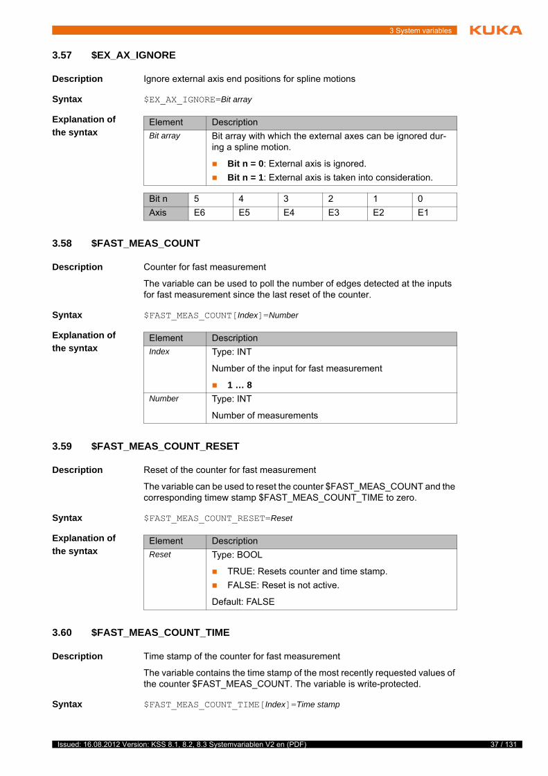
3 System variables
3.57 $EX_AX_IGNORE
Description Ignore external axis end positions for spline motions
Syntax $EX_AX_IGNORE=Bit array
Explanation of
the syntax
3.58 $FAST_MEAS_COUNT
Description Counter for fast measurement
The variable can be used to poll the number of edges detected at the inputs for fast measurement since the last reset of the counter.
Syntax $FAST_MEAS_COUNT[Index]=Number
Explanation of
the syntax
3.59 $FAST_MEAS_COUNT_RESET
Description Reset of the counter for fast measurement
The variable can be used to reset the counter $FAST_MEAS_COUNT and the corresponding timew stamp $FAST_MEAS_COUNT_TIME to zero.
Syntax $FAST_MEAS_COUNT_RESET=Reset
Explanation of
the syntax
3.60 $FAST_MEAS_COUNT_TIME
Description Time stamp of the counter for fast measurement
The variable contains the time stamp of the most recently requested values of the counter $FAST_MEAS_COUNT. The variable is write-protected.
Syntax $FAST_MEAS_COUNT_TIME[Index]=Time stamp
Element Description
Bit array Bit array with which the external axes can be ignored dur-ing a spline motion.
Bit n = 0: External axis is ignored.
Bit n = 1: External axis is taken into consideration.
Bit n 5 4 3 2 1 0
Axis E6 E5 E4 E3 E2 E1
Element Description
Index Type: INT
Number of the input for fast measurement
1 … 8
Number Type: INT
Number of measurements
Element Description
Reset Type: BOOL
TRUE: Resets counter and time stamp.
FALSE: Reset is not active.
Default: FALSE
37 / 131Issued: 16.08.2012 Version: KSS 8.1, 8.2, 8.3 Systemvariablen V2 en (PDF)

38 / 131
System Variables
Explanation of
the syntax
3.61 $FILTER
Description Programmed smooth ramp in the advance run
The variable can be used to set the filter value for motions in the robot pro-gram. The filter prevents an abrupt increase to the maximum acceleration val-ue. The motion time of a motion instruction is extended by an integer multiple of the interpolation cycle (12 ms).
Motion time extension = $FILTER * IPO cycle
Syntax $FILTER=Filter value
Explanation of
the syntax
3.62 $FILTER_C
Description Currently valid smooth ramp in the main run
The variable displays the currently valid filter value for motions.
Syntax $FILTER_C=Filter value
Explanation of
the syntax
3.63 $FLAG
Description Management of flags
A Boolean expression can be freely assigned to the variable $FLAG in a robot or submit program. This Boolean expression is only evaluated at the time of assignment.
Syntax $FLAG[Number]=Boolean expression
Element Description
Index Type: INT
Number of the input for fast measurement
1 … 8
Time stamp Type: REAL
Element Description
Filter value Type: INT
0 ... 16
If the filter value is zero, the filter is deactivated.
The variable is write-protected and can only be read.
Element Description
Filter value Type: INT
0 ... 16
If the filter value is zero, the filter is deactivated.
Issued: 16.08.2012 Version: KSS 8.1, 8.2, 8.3 Systemvariablen V2 en (PDF)

3 System variables
Explanation of
the syntax
3.64 $FOL_ERROR
Description Following error of an axis relative to the velocity
Syntax $FOL_ERROR[Axis number]=Following error
Explanation of
the syntax
3.65 $FCT_CALL
Description Management number (handle) for command channel $FCT_CALL
The CWRITE( ) function can be used to call functions via the $FCT_CALL command channel. The variable itself is write-protected.
Syntax $FCT_CALL=Number
Explanation of
the syntax
3.66 $GEAR_JERK
Description Gear jerk of the axes in the advance run
The variable is used to define the gear jerk of an axis. The gear jerk is specified as a percentage value of the corresponding machine data in the dynamic mod-el $DYN_DAT[].
If $GEAR_JERK is not initialized at the start of a spline motion, e.g. because the INI line has not been executed, the acknowledgement message Gear jerk not programmed {Axis number} is displayed and program execution is stopped.
Syntax $GEAR_JERK[Axis number]=Gear jerk
Element Description
Number Type: INT
1 … 1,024
Boolean expression
Type: BOOL
TRUE, FALSE or other Boolean expression
Default: FALSE
Element Description
Axis number Type: INT
1 … 6: Robot axis A1 ... A6
7 … 12: External axis E1 … E6
Following error
Type: REAL; unit: ms
Detailed information on the CWRITE() command can be found in the CREAD/CWRITE documentation.
Element Description
Number Type: INT
39 / 131Issued: 16.08.2012 Version: KSS 8.1, 8.2, 8.3 Systemvariablen V2 en (PDF)

40 / 131
System Variables
Explanation of
the syntax
3.67 $GEAR_JERK_C
Description Gear jerk of the axes in the main run
The variable contains the currently valid gear jerk of an axis. The gear jerk is specified as a percentage value of the corresponding machine data in the dy-namic model $DYN_DAT[].
Syntax $GEAR_JERK_C[Axis number]=Gear jerk
Explanation of
the syntax
3.68 $HOLDING_TORQUE
Description Holding torque of an axis
The variable contains the holding torque of an axis calculated in the dynamic model $DYN_DAT[]. The holding torque refers to the current actual position of the axis and the current load.
The variable is write-protected. Its value is not dependent on the interpreter. In the robot program, the variable triggers an advance run stop.
Syntax $HOLDING_TORQUE[Axis number]=Holding torque
Element Description
Axis number Type: INT
1 … 6: Robot axis A1 ... A6
7 … 12: External axis E1 … E6
Gear jerk Type: INT; unit: %
1 … 100
The variable is write-protected and can only be read.
Element Description
Axis number Type: INT
1 … 6: Robot axis A1 ... A6
7 … 12: External axis E1 … E6
Gear jerk Type: INT; unit: %
1 … 100
The system variable for torque mode is available in KUKA System Software 8.2 and higher.
If the upper and lower torque limits are set to $HOLDING_TORQUE for all axes, the robot must remain stationary when the brakes are re-leased.
If this is not the case, i.e. if the robot drifts, the load is not correctly configured.
Issued: 16.08.2012 Version: KSS 8.1, 8.2, 8.3 Systemvariablen V2 en (PDF)

3 System variables
Explanation of
the syntax
3.69 $HOLDING_TORQUE_MAND
Description Monitoring of the holding torque of an axis
If torque mode is activated with the function SET_TORQUE_LIMITS(), moni-toring is carried out by default to check whether the holding torque (axes with dynamic model) or zero torque (axes without dynamic model) are in the pro-grammed interval. This permissibility of the limits is only checked at the time of activation.
The purpose of the variable is to prevent unintentionally hazardous program-ming by means of SET_TORQUE_LIMITS(), as for normal applications the potentially dangerous state of allowing less than the holding torque is neither required nor intentional. Programmers who are aware of the effects and have to use the feature can deactivate the monitoring by writing to the variable. For this, the variable $HOLDING_TORQUE_MAND[] must be set to FALSE imme-diately before SET_TORQUE_LIMITS() and then reset.
Syntax $HOLDING_TORQUE_MAND[Axis number]=State
Explanation of
the syntax
3.70 $HOME
Description HOME directory of the compiler
Syntax $HOME[]="Directory"
Explanation of
the syntax
Element Description
Axis number Type: INT
1 … 6: Robot axis A1 ... A6
7 … 12: External axis E1 … E6
Holding tor-que
Type: REAL; unit: Nm (for linear axes: N)
Note: For external axes, the value 0 is always returned, as there are currently no model data defined for them.
The system variable for torque mode is available in KUKA System Software 8.2 and higher.
Element Description
Axis number Type: INT
1 … 6: Robot axis A1 ... A6
7 … 12: External axis E1 … E6
State Type: BOOL
TRUE: Monitoring is activated.
FALSE: Monitoring is deactivated.
Default: TRUE
Element Description
Directory Type: CHAR (max. 3 characters)
/R1: Robot system 1
/R2: Robot system 2
Default: /R1
41 / 131Issued: 16.08.2012 Version: KSS 8.1, 8.2, 8.3 Systemvariablen V2 en (PDF)

42 / 131
System Variables
3.71 $IN
Description Digital input states
The variable can be used to poll the current state of a digital input in a robot or submit program or via the variable correction function. The variable is write-protected.
Syntax $IN[Input number]=State
Explanation of
the syntax
3.72 $INPOSITION
Description Positioning window reached – axis in position
Syntax $INPOSITION=Bit array
Explanation of
the syntax
3.73 $INTERPRETER
Description Selection of the robot or submit interpreter
By default, the execution of a selected SUB program is not displayed in the ed-itor. This can be changed using the variable $INTERPRETER. The SUB pro-gram can only be displayed, however, if a motion program is selected at the same time.
Syntax $INTERPRETER=Type
Explanation of
the syntax
Element Description
Input number Type: INT
1 … 4,096: KUKA System Software 8.1
1 … 8,192: KUKA System Software 8.2 or higher
Note: The range of values contains the maximum possible number of digital I/Os. The number of digital I/Os actually available can be monitored via $NUM_IN/$NUM_OUT.
State Type: BOOL
TRUE or FALSE
Element Description
Bit array Bit array indicating the axes that have reached the posi-tioning window.
Bit n = 0: Axis still moving
Bit n = 1: Axis in the positioning window
Bit n 12 … 5 4 3 2 1 0
Axis E6 A6 A5 A4 A3 A2 A1
Element Description
Type Type: INT
0: Submit interpreter is selected.
The selected SUB program is displayed in the editor.
1: Robot interpreter is selected.
The selected motion program is displayed in the editor.
Default: 1
Issued: 16.08.2012 Version: KSS 8.1, 8.2, 8.3 Systemvariablen V2 en (PDF)

3 System variables
3.74 $IOBUS_INFO
Description Structure with information about the bus driver
Syntax = $IOBUS_INFO[Index]=Information
Explanation of
the syntax
Iobus_Info_T STRUC Iobus_Info_T CHAR name[256], drv_name[256], BOOL bus_ok, bus_installed
3.75 $IOSIM_IN
Description State of the digital inputs with simulation calculated
The variable can be used to poll the current state of a digital input in the robot program or via the variable correction function. It also specifies whether or not the input is simulated. The variable is write-protected.
Syntax $IOSIM_IN[Input number]="State"
The variable is write-protected and can only be read.
Element Description
Index Type: INT
Bus driver number
1 … 32
The serial number is automatically assigned to the bus drivers.
Information Type: Iobus_Info_T
List with information about the bus driver
Element Description
name[] Name of the bus instance, e.g. SYS-X44
drv_name[] Name of the bus driver, e.g. ECat.DRV
bus_ok TRUE: Bus driver is OK.
FALSE: Bus driver is faulty or incompatible.
bus_installed TRUE: Bus driver is installed.
FALSE: No bus driver installed.
43 / 131Issued: 16.08.2012 Version: KSS 8.1, 8.2, 8.3 Systemvariablen V2 en (PDF)

44 / 131
System Variables
Explanation of
the syntax
3.76 $IOSIM_OPT
Description Activation or deactivation of simulation
Precondition KUKA.OfficeLite is used or an image of the system software is running on the office PC.
Syntax $IOSIM_OPT=State
Explanation of
the syntax
Properties If simulation is activated, the robot controller takes simulated inputs and outputs into account.
(Inputs and outputs are simulated by means of the system variables $INSIM_TBL and $OUTSIM_TBL.)
Outputs can only be set if the enabling switch is pressed.
If simulation is not activated, the robot controller takes account of the real state of all inputs and outputs, and the simulated state is not relevant.
Robot controller response:
If an output[x] is simulated, its real state (i.e. $OUT[x]) can no longer be modified. To allow this, the simulated state of the output must first be reset.
The robot controller processes both simulated input signals and real input signals. If an input has been mapped to a robot controller output, the sim-ulated input also sets the physical output!
When simulation is deactivated again:
All outputs resume the state they had prior to simulation.
All inputs resume their real state.
When the robot controller is rebooted:
Simulation is automatically deactivated.
The simulated state of each input and output is reset.
Element Description
Input number Type: INT
1 … 4,096: KUKA System Software 8.1
1 … 8,192: KUKA System Software 8.2 or higher
Note: The range of values contains the maximum possible number of digital I/Os. The number of digital I/Os actually available can be monitored via $NUM_IN/$NUM_OUT.
State Type: CHAR
0: FALSE and not simulated
1: TRUE and not simulated
2: FALSE and simulated
3: TRUE and simulated
4: FALSE and not simulated and system input
5: TRUE and not simulated and system input
6: FALSE and simulated and system input
7: TRUE and simulated and system input
Element Description
State Type: BOOL
FALSE: The simulation is deactivated.
TRUE: Simulation is activated.
Default: FALSE
Issued: 16.08.2012 Version: KSS 8.1, 8.2, 8.3 Systemvariablen V2 en (PDF)

3 System variables
3.76.1 Simulating inputs/outputs – KUKA System Software 8.2 or higher
Example 1 State before simulation: $OUT[8]==FALSE
1. The simulated state of the output is set to TRUE. ($OUTSIM_TBL[8]="1")
2. Simulation is activated. ($IOSIM_OPT =TRUE)
The real state now reflects the simulated state, i.e. $OUT[8]==TRUE.
$OUT[8] can no longer be modified.
3. Simulation is deactivated. ($IOSIM_OPT =FALSE)
Now $OUT[8]==FALSE!
Deactivation of the simulation has reset $OUT[8] to the state it had before the simulation, i.e. FALSE. $OUT[8] can now be modified again.
Example 2 State before simulation: $OUT[9]==FALSE.
Furthermore, $OUTSIM_TBL[9]="-", i.e. the output is not simulated.
1. Simulation is activated. ($IOSIM_OPT =TRUE)
2. The real state of the output is changed to TRUE. ($OUT[9]=TRUE)
3. Simulation is deactivated again. ($IOSIM_OPT=FALSE)
Now $OUT[9]==FALSE!
Deactivation of the simulation has reset $OUT[9] to the state it had before the simulation, i.e. FALSE.
3.76.2 Simulating inputs/outputs – KUKA System Software 8.1
Example 1 State before simulation: $OUT[8]==FALSE
1. The simulated state of the output is set to TRUE. ($OUTSIM_TBL[8]=#SIM_TRUE)
2. Simulation is activated. ($IOSIM_OPT =TRUE)
The real state now reflects the simulated state, i.e. $OUT[8]==TRUE.
$OUT[8] can no longer be modified.
3. Simulation is deactivated. ($IOSIM_OPT =FALSE)
Now $OUT[8]==FALSE!
Deactivation of the simulation has reset $OUT[8] to the state it had before the simulation, i.e. FALSE. $OUT[8] can now be modified again.
Example 2 State before simulation: $OUT[9]==FALSE.
Furthermore, $OUTSIM_TBL[9]==#NONE, i.e. the output is not simulated.
1. Simulation is activated. ($IOSIM_OPT =TRUE)
2. The real state of the output is changed to TRUE. ($OUT[9]=TRUE)
3. Simulation is deactivated again. ($IOSIM_OPT=FALSE)
Now $OUT[9]==FALSE!
Deactivation of the simulation has reset $OUT[9] to the state it had before the simulation, i.e. FALSE.
3.77 $IOSIM_OUT
Description State of the digital outputs with simulation calculated
The variable can be used to poll the current state of a digital output in the robot program or via the variable correction function. It also specifies whether or not the output is simulated. The variable is write-protected.
45 / 131Issued: 16.08.2012 Version: KSS 8.1, 8.2, 8.3 Systemvariablen V2 en (PDF)

46 / 131
System Variables
Syntax $IOSIM_OUT[Output number]="State"
Explanation of
the syntax
3.78 $IOSYS_IN_FALSE
Description Number of the system input that is always FALSE
By default, input $IN[1026], which is always FALSE, is configured as a system input.
In the VW System Software, a different system input can be configured. The number of this system input can be polled using the variable.
Syntax $IOSYS_IN_FALSE=Input number
Explanation of
the syntax
3.79 $IOSYS_IN_TRUE
Description Number of the system input that is always TRUE
By default, input $IN[1025], which is always TRUE, is configured as a system input.
In the VW System Software, a different system input can be configured. The number of this system input can be polled using the variable.
Syntax $IOSYS_IN_TRUE=Input number
Element Description
Output number
Type: INT
1 … 4,096: KUKA System Software 8.1
1 … 8,192: KUKA System Software 8.2 or higher
Note: The range of values contains the maximum possible number of digital I/Os. The number of digital I/Os actually available can be monitored via $NUM_IN/$NUM_OUT.
State Type: CHAR
0: FALSE and not simulated
1: TRUE and not simulated
2: FALSE and simulated
3: TRUE and simulated
4: FALSE and not simulated and system input
5: TRUE and not simulated and system input
6: FALSE and simulated and system input
7: TRUE and simulated and system input
The variable is write-protected and can only be read.
Element Description
Input number Type: INT
Default: 1026
The variable is write-protected and can only be read.
Issued: 16.08.2012 Version: KSS 8.1, 8.2, 8.3 Systemvariablen V2 en (PDF)

3 System variables
Explanation of
the syntax
3.80 $IPO_MODE
Description Programmed interpolation mode in the advance run
Syntax $IPO_MODE=Mode
Explanation of
the syntax
3.81 $IPO_MODE_C
Description Current interpolation mode in the main run
Syntax $IPO_MODE_C=Mode
Explanation of
the syntax
3.82 $IPO_WAIT_FOR
Description Name of the workspace outside of which the robot is waiting
The workspace is currently disabled and the robot is waiting for the requested workspace to be enabled.
The variable is used to generate a message on the smartHMI indicating the name of the workspace for which the robot is waiting. The variable is write-pro-tected.
Syntax $IPO_WAIT_FOR[]="Name"
Explanation of
the syntax
Element Description
Input number Type: INT
Default: 1025
Element Description
Mode Type: ENUM
#TCP: The tool is a fixed tool.
#BASE: The tool is mounted on the mounting flange.
Default: #BASE
The variable is write-protected and can only be read.
Element Description
Mode Type: ENUM
#TCP: The tool is a fixed tool.
#BASE: The tool is mounted on the mounting flange.
Default: #BASE
Only relevant if KUKA.RoboTeam is used.
Element Description
Name Type: CHAR
Workspace name: max. 2047 characters
47 / 131Issued: 16.08.2012 Version: KSS 8.1, 8.2, 8.3 Systemvariablen V2 en (PDF)

48 / 131
System Variables
3.83 $IPO_WAIT_FOR_ON
Description Interpolator flag that displays the wait for enabling of a workspace
The variable indicates whether the workspace is currently disabled and the ro-bot is waiting for the requested workspace to be enabled.
Syntax $IPO_WAIT_FOR_ON=State
Explanation of
the syntax
3.84 $IPO_WAIT_STATE
Description Interpolator flag that displays the wait condition
Syntax $IPO_WAIT_STATE=State
Explanation of
the syntax
3.85 $IS_OFFICE_LITE
Description Identifier of the System Software as OfficeLite version
Syntax $IS_OFFICE_LITE=Identifier
Explanation of
the syntax
3.86 $I2T_OL
Description Deactivation of I2t monitoring (only permissible in KUKA.OfficeLite)
Syntax $I2T_OL=State
Only relevant if KUKA.RoboTeam is used.
Element Description
State Type: BOOL
TRUE: Robot is waiting for enabling.
FALSE: Workspace is enabled.
Only relevant if KUKA.RoboTeam is used.
The variable is write-protected and can only be read.
Element Description
State Type: ENUM
#NOT_WAITING : There is no wait condition active.
#WAIT_WORKSPACE: Robot waiting for requested workspace to be enabled.
Element Description
Identifier Type: BOOL
TRUE: Software is KUKA.OfficeLite.
FALSE: Software is KUKA System Software.
Issued: 16.08.2012 Version: KSS 8.1, 8.2, 8.3 Systemvariablen V2 en (PDF)

3 System variables
Explanation of
the syntax
3.87 $JERK
Description Cartesian jerk limitation for SPLINE in the advance run
The variable of structure type JERK_STRUC limits the change of the acceler-ation over time during CP spline motions (SLIN, SCIRC).
The aggregate consists of the following components:
CP: Change to the path acceleration in [m/s3]
ORI: Change to the orientation acceleration in [°/s3]
AX: Change to the axis acceleration in [°/s3] for rotational axes or in [m/s3] for linear axes
The maximum permissible jerk for SPLINE motions is defined in the machine data (variable $JERK_MA in the file …R1\Mada\$machine.dat).
Example
3.88 $JERK_C
Description Cartesian jerk limitation for SPLINE in the main run
The variable of structure type JERK_STRUC contains the current value for the change of the acceleration over time during a CP SPLINE motion (SLIN, SCIRC).
The aggregate consists of the following components:
CP: Change to the path acceleration in [m/s3]
ORI: Change to the orientation acceleration in [°/s3]
AX: Change to the axis acceleration in [°/s3] for rotational axes or in [m/s3] for linear axes
Element Description
State Type: ENUM
#ON: I2t monitoring is activated.
#OFF: I2t monitoring is not activated.
Default: #ON
The variable is only relevant in the case of CP spline motions that are planned without a dynamic model. (Only KUKA System Software 8.1. From KUKA System Software 8.2 onwards, the variable is no longer
relevant.)
$JERK={CP 50.0,ORI 50000.0,AX {A1 1000.0,A2 1000.0,A3 1000.0,A4 1000.0,A5 1000.0,A6 1000.0,E1 1000.0,E2 1000.0,E3 1000.0,E4 1000.0,E5 1000.0,E6 1000.0}}
The variable is only relevant in the case of CP spline motions that are planned without a dynamic model. (Only KUKA System Software 8.1. From KUKA System Software 8.2 onwards, the variable is no longer
relevant.)
The variable is write-protected and can only be read.
49 / 131Issued: 16.08.2012 Version: KSS 8.1, 8.2, 8.3 Systemvariablen V2 en (PDF)

50 / 131
System Variables
3.89 $KCP_CONNECT
Description Displays whether a KUKA smartPad is connected.
Syntax $KCP_CONNECT=State
Explanation of
the syntax
3.90 $KCP_IP
Description IP address of the currently connected KUKA smartPad
Syntax $KCP_IP=IP address
Explanation of
the syntax
3.91 $KCP_TYPE
Description Currently connected teach pendant
The variable can be used to monitor whether a teach pendant is currently con-nected to the robot controller and, if so, which type.
Syntax $KCP_TYPE=Type
Explanation of
the syntax
3.92 $KDO_ACT
Description Indication of whether a command motion is currently active
Examples of command motions are jog motions and motions of asynchronous axes.
Syntax $KDO_ACT=State
Element Description
State Type: BOOL
TRUE: smartPad is connected.
FALSE: No smartPad is connected.
The system variable is available in KUKA System Software 8.2 and higher.
Element Description
IP address Type: INT
If the value zero is displayed, no smartPad is currently con-nected.
The system variable is available in KUKA System Software 8.2 and higher.
Element Description
Type Type: ENUM
#NO_KCP: No teach pendant is connected.
#KCP: KUKA smartPad is connected.
#VRP: A virtual KUKA smartPad is connected (KU-KA.VirtualRemotePendant).
Issued: 16.08.2012 Version: KSS 8.1, 8.2, 8.3 Systemvariablen V2 en (PDF)

3 System variables
Explanation of
the syntax
3.93 $KR_SERIALNO
Description Robot serial number saved on the RDC
Syntax $KR_SERIALNO=Number
Explanation of
the syntax
3.94 $LDC_ACTIVE
Description Activation/deactivation of online load data verification
Precondition Online load data verification is loaded: $LDC_LOADED=TRUE
Syntax $LDC_ACTIVE=State
Explanation of
the syntax
3.95 $LDC_LOADED
Description Indication of whether online load data verification is loaded
The variable can be used to check whether online load data verification for the current robot type is available. Online load data verification is available for those robot types for which KUKA.LoadDataDetermination can be used.
Syntax $LDC_LOADED=State
Explanation of
the syntax
Element Description
State Type: BOOL
TRUE: Command motion active.
FALSE: No command motion active.
Element Description
Number Type: INT
Maximum 24 characters
The system variable is available in KUKA System Software 8.2 and higher.
Element Description
State Type: BOOL
TRUE: Online load data verification is activated.
FALSE: Online load data verification is deactivated.
Default: TRUE
The system variable is available in KUKA System Software 8.2 and higher.
Element Description
State Type: BOOL
TRUE: Online load data verification is loaded.
FALSE: Online load data verification is not loaded.
51 / 131Issued: 16.08.2012 Version: KSS 8.1, 8.2, 8.3 Systemvariablen V2 en (PDF)

52 / 131
System Variables
3.96 $LDC_RESULT
Description Current result of the online load data verification
Syntax $LDC_RESULT[Index]= Result
Explanation of
the syntax
3.97 $LK_MASTER
Description Name or IP address of the current LK master (Linked Kinematic Master)
The variable indicates the current motion master in a RoboTeam. This is a ro-bot that can move without a command being issued (e.g. by pressing the Start key or a jog key).
Syntax $LK_MASTER[]="Name"
Explanation of
the syntax
3.98 $LK_SLAVES
Description List with the names or IP addresses of the current LK slaves (Linked Kinematic Slaves)
The variable indicates the current motion slave if there is at least one other controller coupled to the local controller. This means that at least one robot also moves when the local robot or an external kinematic system is moved.
Syntax $LK_SLAVES[]="List"
The system variable is available in KUKA System Software 8.2 and higher.
Element Description
Index Type: INT
Tool number
1 … 32
Result Type: CHAR
#OK: The payload is OK. (Neither overload nor under-load.)
#OVERLOAD: There is an overload.
#UNDERLOAD: There is an underload.
#CHECKING: There are currently no results because load data verification is still active.
#NONE: There are currently no results, e.g. because the tool has been changed.
Element Description
Name Type: CHAR
Name or IP address of the robot controller: max. 50 char-acters
Note: If the variable is blank, the robot controller is inde-pendent, i.e. not part of a RoboTeam.
Issued: 16.08.2012 Version: KSS 8.1, 8.2, 8.3 Systemvariablen V2 en (PDF)

3 System variables
Explanation of
the syntax
3.99 $LOAD
Description Currently valid load data in the advance run
The structure contains the payload data entered in the robot controller and as-signed to the current tool. The reference coordinate system is the FLANGE co-ordinate system.
(>>> "Loads on the robot" Page 53)
Syntax $LOAD={M Mass, CM Center of gravity, J Inertia}
Explanation of
the syntax
Loads on the
robot
Various loads can be mounted on the robot:
Payload on the flange
Supplementary load on axis 3
Supplementary load on axis 2
Supplementary load on axis 1
Element Description
List Type: CHAR
List with the names or IP addresses of the currently cou-pled robot controllers: max. 100 characters
Element Description
Mass Type: REAL; unit: kg
Center of gra-vity
Type: FRAME
X, Y, Z: Position of the center of gravity relative to the flange
A, B, C: Orientation of the principal inertia axes relative to the flange
Inertia Type: INERTIA
X, Y, Z: Mass moments of inertia about the axes of the coordinate system that is rotated relative to the flange by A, B and C.
53 / 131Issued: 16.08.2012 Version: KSS 8.1, 8.2, 8.3 Systemvariablen V2 en (PDF)

54 / 131
System Variables
Parameters The load data are defined using the following parameters:
Reference systems of the X, Y and Z values for each load:
3.100 $LOAD_C
Description Currently valid load data in the main run
Fig. 3-4: Loads on the robot
1 Payload 3 Supplementary load on axis 2
2 Supplementary load on axis 3 4 Supplementary load on axis 1
Parameter Unit
Mass m kg
Distance to the center of gravity
Lx, Ly, Lz mm
Mass moments of iner-tia at the center of gravity
Ix, Iy, Iz kg m2
Load Reference system
Payload FLANGE coordinate system
Supplementary load A3
FLANGE coordinate system
A4 = 0°, A5 = 0°, A6 = 0°
Supplementary load A2
ROBROOT coordinate system
A2 = -90°
Supplementary load A1
ROBROOT coordinate system
A1 = 0°
Issued: 16.08.2012 Version: KSS 8.1, 8.2, 8.3 Systemvariablen V2 en (PDF)

3 System variables
The structure contains the payload data entered in the robot controller and as-signed to the current tool. The reference coordinate system is the FLANGE co-ordinate system.
(>>> "Loads on the robot" Page 53)
Syntax $LOAD_C={M Mass, CM Center of gravity, J Inertia}
Explanation of
the syntax
3.101 $LOAD_A1
Description Currently valid supplementary load data for axis A1 in the advance run
The structure contains the supplementary load data of the load mounted on axis A1 and entered in the robot controller.
(>>> "Loads on the robot" Page 53)
The reference coordinate system is the ROBROOT coordinate system with A1= 0°.
Syntax $LOAD_A1={M Mass, CM Center of gravity, J Inertia}
Explanation of
the syntax
3.102 $LOAD_A1_C
Description Currently valid supplementary load data for axis A1 in the main run
The structure contains the supplementary load data of the load mounted on axis A1 and entered in the robot controller.
(>>> "Loads on the robot" Page 53)
The variable is write-protected and can only be read.
Element Description
Mass Type: REAL; unit: kg
Center of gra-vity
Type: FRAME
X, Y, Z: Position of the center of gravity relative to the flange
A, B, C: Orientation of the principal inertia axes relative to the flange
Inertia Type: INERTIA
X, Y, Z: Mass moments of inertia about the axes of the coordinate system that is rotated relative to the flange by A, B and C.
Element Description
Mass Type: REAL; unit: kg
Center of gra-vity
Type: FRAME
X, Y, Z: Position of the center of gravity relative to the robot base
A, B, C: Orientation of the principal inertia axes relative to the robot base
Inertia Type: INERTIA
X, Y, Z: Mass moments of inertia about the axes of the coordinate system that is rotated relative to the robot base by A, B and C.
55 / 131Issued: 16.08.2012 Version: KSS 8.1, 8.2, 8.3 Systemvariablen V2 en (PDF)

56 / 131
System Variables
The reference coordinate system is the ROBROOT coordinate system with A1= 0°.
Syntax $LOAD_A1_C={M Mass, CM Center of gravity, J Inertia}
Explanation of
the syntax
3.103 $LOAD_A2
Description Currently valid supplementary load data for axis A2 in the advance run
The structure contains the supplementary load data of the load mounted on axis A2 and entered in the robot controller.
(>>> "Loads on the robot" Page 53)
The reference coordinate system is the ROBROOT coordinate system with A2= -90°.
Syntax $LOAD_A2={M Mass, CM Center of gravity, J Inertia}
Explanation of
the syntax
3.104 $LOAD_A2_C
Description Currently valid supplementary load data for axis A2 in the main run
The structure contains the supplementary load data of the load mounted on axis A2 and entered in the robot controller.
The variable is write-protected and can only be read.
Element Description
Mass Type: REAL; unit: kg
Center of gra-vity
Type: FRAME
X, Y, Z: Position of the center of gravity relative to the robot base
A, B, C: Orientation of the principal inertia axes relative to the robot base
Inertia Type: INERTIA
X, Y, Z: Mass moments of inertia about the axes of the coordinate system that is rotated relative to the robot base by A, B and C.
In the case of a 4-axis SCARA robot, the reference coordinate system is the ROBROOT coordinate system with A2= 0°.
Element Description
Mass Type: REAL; unit: kg
Center of gra-vity
Type: FRAME
X, Y, Z: Position of the center of gravity relative to the robot base
A, B, C: Orientation of the principal inertia axes relative to the robot base
Inertia Type: INERTIA
X, Y, Z: Mass moments of inertia about the axes of the coordinate system that is rotated relative to the robot base by A, B and C.
Issued: 16.08.2012 Version: KSS 8.1, 8.2, 8.3 Systemvariablen V2 en (PDF)

3 System variables
(>>> "Loads on the robot" Page 53)
The reference coordinate system is the ROBROOT coordinate system with A2= -90°.
Syntax $LOAD_A2_C={M Mass, CM Center of gravity, J Inertia}
Explanation of
the syntax
3.105 $LOAD_A3
Description Currently valid supplementary load data for axis A3 in the advance run
The structure contains the supplementary load data of the load mounted on axis A3 and entered in the robot controller.
(>>> "Loads on the robot" Page 53)
The reference coordinate system is the FLANGE coordinate system with A4= 0°, A5= 0° and A6= 0°.
Syntax $LOAD_A3={M Mass, CM Center of gravity, J Inertia}
Explanation of
the syntax
3.106 $LOAD_A3_C
Description Currently valid supplementary load data for axis A3 in the main run
In the case of a 4-axis SCARA robot, the reference coordinate system is the ROBROOT coordinate system with A2= 0°.
The variable is write-protected and can only be read.
Element Description
Mass Type: REAL; unit: kg
Center of gra-vity
Type: FRAME
X, Y, Z: Position of the center of gravity relative to the robot base
A, B, C: Orientation of the principal inertia axes relative to the robot base
Inertia Type: INERTIA
X, Y, Z: Mass moments of inertia about the axes of the coordinate system that is rotated relative to the robot base by A, B and C.
Element Description
Mass Type: REAL; unit: kg
Center of gra-vity
Type: FRAME
X, Y, Z: Position of the center of gravity relative to the flange
A, B, C: Orientation of the principal inertia axes relative to the flange
Inertia Type: INERTIA
X, Y, Z: Mass moments of inertia about the axes of the coordinate system that is rotated relative to the flange by A, B and C.
57 / 131Issued: 16.08.2012 Version: KSS 8.1, 8.2, 8.3 Systemvariablen V2 en (PDF)

58 / 131
System Variables
The structure contains the supplementary load data of the load mounted on axis A3 and entered in the robot controller.
(>>> "Loads on the robot" Page 53)
The reference coordinate system is the FLANGE coordinate system with A4= 0°, A5= 0° and A6= 0°.
Syntax $LOAD_A3_C={M Mass, CM Center of gravity, J Inertia}
Explanation of
the syntax
3.107 $MAMES_ACT
Description Robot-specific mastering position
The mastering position for each axis of a specific robot type is defined by means of $MAMES in the machine data.
The robot-specific mastering position $MAMES_ACT may deviate slightly. The offset relative to the mastering position stored in $MAMES is then saved as a MAM file on the RDC.
If offset values for the mastering are saved and are to be used, this must be specified in the machine data with $INDIVIDUAL_MAMES. The robot control-ler then reads the offset values during booting, adds them to the MAMES val-ues and writes the result to the variable $MAMES_ACT.
If a MAM file with offset data is to be used, $INDIVIDUAL_MAMES ≠ #NONE, $MAMES_ACT = $MAMES + MAM offset.
If a MAM file with offset data is to be used, $INDIVIDUAL_MAMES ≠ #NONE, but no MAM file is saved, $MAMES_ACT is invalid.
If a MAM file with offset data is not to be used, $INDIVIDUAL_MAMES = #NONE, $MAMES_ACT = $MAMES.
Syntax $MAMES_ACT[Axis number]=Axis value
The variable is write-protected and can only be read.
Element Description
Mass Type: REAL; unit: kg
Center of gra-vity
Type: FRAME
X, Y, Z: Position of the center of gravity relative to the flange
A, B, C: Orientation of the principal inertia axes relative to the flange
Inertia Type: INERTIA
X, Y, Z: Mass moments of inertia about the axes of the coordinate system that is rotated relative to the flange by A, B and C.
The variable is write-protected and can only be read.
Issued: 16.08.2012 Version: KSS 8.1, 8.2, 8.3 Systemvariablen V2 en (PDF)

3 System variables
Explanation of
the syntax
Example The MAMES value in the machine data for A3 is 90°. In the MAM file, an offset of 1° is saved for this axis:
$MAMES_ACT[3] = 90.0 + 1.0 = 91.0
3.108 $MASTERINGTEST_GROUP
Description Number of the reference group in reference position
If a robot is to be monitored safely, a mastering test must be performed. Up to 3 reference groups can be defined for the reference run.
The variable specifies the reference group that is currently in the reference po-sition.
Syntax $MASTERINGTEST_GROUP=Number
Explanation of
the syntax
3.109 $MASTERINGTEST_REQ_INT
Description Internal mastering test request
If a robot is to be monitored safely, a mastering test must be performed. Once the robot controller has booted or mastering has been carried out, the safety controller internally requests the mastering test and sets the variable to TRUE.
Syntax $MASTERINGTEST_REQ_INT=Request
Explanation of
the syntax
Element Description
Axis number Type: INT
1 … 6: Robot axis A1 ... A6
7 … 12: External axis E1 … E6
Axis value Type: REAL; unit: ° (for linear axes: mm)
-180° … +180°
Only relevant if KUKA.SafeOperation or KUKA.SafeRangeMonitoring is installed.
Element Description
Number Type: INT
0: No reference group in position
1 … 3: Reference group with this number in position
Only relevant if KUKA.SafeOperation or KUKA.SafeRangeMonitoring is installed.
Element Description
Request Type: BOOL
TRUE: Mastering test has been requested.
FALSE: Mastering test has not been requested.
Default: FALSE
59 / 131Issued: 16.08.2012 Version: KSS 8.1, 8.2, 8.3 Systemvariablen V2 en (PDF)

60 / 131
System Variables
3.110 $MEAS_PULSE
Description Activation of the inputs for fast measurement
The variable can be used to activate fast measurement via an interrupt. When the interrupt is activated, $MEAS_PULSE must have the value FALSE, other-wise an acknowledgement message is generated and the program is stopped.
Syntax $MEAS_PULSE[Measurement input number]=State
Explanation of
the syntax
3.111 $MODE_OP
Description Current operating mode
Syntax $MODE_OP=Operating mode
Explanation of
the syntax
3.112 $MOT_STOP
Description Disabling of the external start
The variable is set if the robot is not on the programmed path and the external start is disabled. The robot controller resets the variable if the user answers Yes to the prompt for confirmation of whether the robot should nevertheless be started. The external start from the higher-level controller is issued subse-quently in this case.
Precondition “Block external start” option is active: $MOT_STOP_OPT=TRUE (variable in the file …\R1\STEU\Mada\$option.dat)
Syntax $MOT_STOP=State
Further information about the inputs for fast measurement (interface X33) can be found in the documentation Optional interfaces for the KR C4.
Element Description
Measu-rement input number
Type: INT
1 … 8
State Type: BOOL
TRUE: Measurement input is active.
FALSE: Measurement input is not active.
Default: FALSE
Element Description
Operating mode
Type: ENUM
#AUT: Automatic
#EX: Automatic external
#T1
#T2
Issued: 16.08.2012 Version: KSS 8.1, 8.2, 8.3 Systemvariablen V2 en (PDF)

3 System variables
Explanation of
the syntax
3.113 $MOT_TEMP
Description Current motor temperature of an axis
In the case of master/slave axes, only the motor temperature of the master drive can be read.
Syntax $MOT_TEMP[Axis number]=Temperature
Explanation of
the syntax
3.114 $MOUSE_ACT
Description Operating state of the Space Mouse
Syntax $MOUSE_ACT=State
Explanation of
the syntax
3.115 $MOUSE_DOM
Description Jog mode of the Space Mouse
Syntax $MOUSE_DOM=Mode
Explanation of
the syntax
Element Description
State Type: BOOL
TRUE: External start is blocked.
FALSE: External start is not blocked.
Default: FALSE
Element Description
Axis number Type: INT
1 … 6: Robot axis A1 ... A6
7 … 12: External axis E1 … E6
Temperature Type: INT; unit: Kelvin; tolerance: ±12 Kelvin
The value zero is displayed for axes that are not config-ured.
Element Description
State Type: BOOL
TRUE: Space Mouse is active.
FALSE: Space Mouse is not active.
Default: FALSE
Element Description
Mode Type: BOOL
TRUE: Dominant mode is active.
Only the coordinate axis with the greatest deflection of the Space Mouse is moved.
FALSE: Dominant mode is not active.
Depending on the axis selection, either 3 or 6 axes can be moved simultaneously.
Default: TRUE
61 / 131Issued: 16.08.2012 Version: KSS 8.1, 8.2, 8.3 Systemvariablen V2 en (PDF)

62 / 131
System Variables
3.116 $MOUSE_ON
Description Activation/deactivation of the Space Mouse on the smartPad
Syntax $MOUSE_ON=State
Explanation of
the syntax
3.117 $MOUSE_ROT
Description Rotational motions with the Space Mouse On/Off
Syntax $MOUSE_ROT=State
Explanation of
the syntax
3.118 $MOUSE_TRA
Description Translational motions with the Space Mouse On/Off
Syntax $MOUSE_TRA=State
Explanation of
the syntax
3.119 $MOVE_BCO
Description Indication of whether a BCO run is currently being executed
Syntax $MOVE_BCO=State
Explanation of
the syntax
3.120 $NULLFRAME
Description NULLFRAME
Element Description
State Type: BOOL
TRUE: Space Mouse is activated.
FALSE: Space Mouse is deactivated.
Default: TRUE
Element Description
State Type: BOOL
TRUE: Rotational motions are possible.
FALSE: Rotational motions are not possible.
Default: TRUE
Element Description
State Type: BOOL
TRUE: Translational motions are possible.
FALSE: Translational motions are not possible.
Default: TRUE
Element Description
State Type: BOOL
TRUE: BCO run is being carried out.
FALSE: BCO run is not being carried out.
Issued: 16.08.2012 Version: KSS 8.1, 8.2, 8.3 Systemvariablen V2 en (PDF)

3 System variables
The variable of structure type FRAME can be used to set all components of a coordinate system to zero:
X, Y, Z: Offset of the origin along the axes in [mm]
A, B, C: Rotational offset of the axis angles in [°]
Example Position of the BASE coordinate system is NULLFRAME
3.121 $NUM_IN
Description Number of available digital inputs $IN
Syntax $NUM_IN=Number
Explanation of
the syntax
3.122 $NUM_OUT
Description Number of available digital outputs $OUT
Syntax $NUM_OUT=Number
Explanation of
the syntax
3.123 $ORI_TYPE
Description Orientation control of a CP motion in the advance run
Syntax $ORI_TYPE=Type
Explanation of
the syntax
$BASE=$NULLFRAME
The variable is write-protected and can only be read.
Element Description
Number Type: INT
The variable is write-protected and can only be read.
Element Description
Number Type: INT
Element Description
Type Type: ENUM
#CONSTANT: The orientation of the TCP remains con-stant during the motion.
#VAR: The orientation of the TCP changes continuously during the motion.
#JOINT: The orientation of the TCP changes continu-ously during the motion. This is done by linear transfor-mation (axis-specific motion) of the wrist axis angles.
Note: If $ORI_TYPE = #JOINT, the variable $CIRC_TYPE is ignored.
63 / 131Issued: 16.08.2012 Version: KSS 8.1, 8.2, 8.3 Systemvariablen V2 en (PDF)

64 / 131
System Variables
3.124 $ORI_TYPE_C
Description Orientation control of a CP motion in the main run
Syntax $ORI_TYPE_C=Type
Explanation of
the syntax
3.125 $OUT
Description Digital output states
The variable can be used to set a digital output in the robot program and then reset it again. Furthermore, the variable can be used to poll the current state of a digital output in the robot program or via the variable correction function.
Syntax $OUT[Output number]=State
Explanation of
the syntax
3.126 $OUT_C
Description Setting of digital outputs in the main run
The variable can be used to set or reset a digital output relative to the main run. The user can use the variable, for example, in order to set a digital output at the target point of an exact positioning motion or at the vertex of an approx-imate positioning motion.
Syntax $OUT_C[Output number]=State
The variable is write-protected and can only be read.
Element Description
Type Type: ENUM
#CONSTANT: The orientation of the TCP remains con-stant during the motion.
#VAR: The orientation of the TCP changes continuously during the motion.
#JOINT: The orientation of the TCP changes continu-ously during the motion. This is done by linear transfor-mation (axis-specific motion) of the wrist axis angles.
Note: If $ORI_TYPE_C = #JOINT, the variable $CIRC_TYPE_C is ignored.
Element Description
Output number
Type: INT
1 … 4,096: KUKA System Software 8.1
1 … 8,192: KUKA System Software 8.2 or higher
Note: The range of values contains the maximum possible number of digital I/Os. The number of digital I/Os actually available can be monitored via $NUM_IN/$NUM_OUT.
State Type: BOOL
TRUE or FALSE
Issued: 16.08.2012 Version: KSS 8.1, 8.2, 8.3 Systemvariablen V2 en (PDF)

3 System variables
Explanation of
the syntax
3.127 $OV_ASYNC
Description Override for coordinated asynchronous motions
The velocity of asynchronous axes is not influenced by the program override (POV). The override for coordinated asynchronous motions (= ASYPTP mo-tion) must be set with $OV_ASYNC in the KRL program. The override is spec-ified as a percentage of the programmed velocity.
Syntax $OV_ASYNC=Override
Explanation of
the syntax
Example
ASYPTP motions are carried out with 20% of the programmed velocity.
3.128 $OV_PRO
Description Program override is the velocity of the robot during program execution. The program override is specified as a percentage of the programmed velocity.
Syntax $OV_PRO=Override
Explanation of
the syntax
Element Description
Output number
Type: INT
1 … 4,096: KUKA System Software 8.1
1 … 8,192: KUKA System Software 8.2 or higher
Note: The range of values contains the maximum possible number of digital I/Os. The number of digital I/Os actually available can be monitored via $NUM_IN/$NUM_OUT.
State Type: BOOL
TRUE or FALSE
In T1 mode, the maximum velocity is 250 mm/s, irrespective of the value that is set.Exception: The velocity reduction for ASYPTP motions in T1 is deac-
tivated (variable $ASYNC_T1_FAST in the file …R1\Mada\$machine.dat). Further information about $ASYNC_T1_FAST can be found in the machine data documentation.
Element Description
Override Type: INT; unit: %
0 … 100
Default: 100
$OV_ASYNC=20
In T1 mode, the maximum velocity is 250 mm/s, irrespective of the value that is set.
Element Description
Override Type: INT; unit: %
0 … 100
Default: 100
65 / 131Issued: 16.08.2012 Version: KSS 8.1, 8.2, 8.3 Systemvariablen V2 en (PDF)

66 / 131
System Variables
3.129 $OV_ROB
Description Robot override
The robot override is the current velocity of the robot in program execution. The variable is write-protected.
The robot override is determined by the program override $OV_PRO as a function of the reduction factor for the program override $RED_VEL. If $RED_VEL=100, i.e. the program override is not reduced, $OV_ROB is iden-tical to $OV_PRO.
Syntax $OV_ROB=Override
Explanation of
the syntax
3.130 $PAL_MODE
Description Activation of palletizing mode (only relevant for palletizing robots)
Depending on the robot type, palletizing mode must either be explicitly activat-ed for this robot or is already activated:
In the case of palletizing robots with 6 axes, palletizing mode is deactivat-ed by default and must be activated. If palletizing mode is active, axis A4 may be locked at 0° and the mounting flange is held parallel to the floor by keeping A5 at a suitable angle. For a 6-axis robot, active palletizing mode is deactivated again after a cold restart of the robot controller.
In the case of palletizing robots with 4 or 5 axes, palletizing mode is active by default.
For 5-axis robots, palletizing mode can be deactivated via $PAL_MODE.
For 4-axis robots, palletizing mode cannot be deactivated via $PAL_MODE.
Syntax $PAL_MODE=State
Explanation of
the syntax
3.131 $PATHTIME
Description Structure with the data of a time-based spline motion (TIME_BLOCK)
The variable can be used to read the data of a time-based spline. $PATHTIME is filled with the data as soon as the robot controller has completed the plan-ning of the spline block. The data are retained until the next spline block has been planned.
Element Description
Override Type: INT; unit: %
0 … 100
Further information about activating the palletizing mode is contained in the Operating and Programming Instructions for System Integra-tors.
Element Description
State Type: BOOL
TRUE: Palletizing mode is active.
FALSE: Palletizing mode is not active.
Default: Dependent on the robot model
Issued: 16.08.2012 Version: KSS 8.1, 8.2, 8.3 Systemvariablen V2 en (PDF)

3 System variables
Syntax Path times=$PATHTIME
Explanation of
the syntax
Pathtime_Struc STRUC Pathtime_Struc REAL total, scheduled, programmed, INT n_sections, REAL max_dev, INT max_dev_section
3.132 $PC_FANSPEED
Description Speed of the PC fan (internal fan)
Syntax $PC_FANSPEED=Speed
Explanation of
the syntax
3.133 $PINGCOOPKRC
Description Accessibility of the cooperating robots in a cell
The variable can be used to display the currently accessible controllers of a RoboTeam. During program execution, status signals are received from the participating controllers via the kernel system network at regular intervals. The absence of a signal indicates that the controller concerned is no longer acces-sible in the network.
Syntax $PINGCOOPKRC=Bit array
Explanation of
the syntax
Example $PINGCOOPKRC = 'B11110'
Element Description
Path times Type: Pathtime_Struc
Data of the time-based spline motion
Element Description
total Time actually required for the entire spline block (s)
scheduled Overall time planned for the time block (s)
pro-grammed
Overall time programmed for the time block (s)
n_sections Number n of time components
max_dev Maximum deviation of all time components between the programmed time and the planned time (%)
max_dev_section
Number of the time component with the greatest deviation between the programmed time and the planned time
Element Description
Speed Type: INT; unit: RPM
Only relevant if KUKA.RoboTeam is used.
Element Description
Bit array Bit array with which the accessible controllers of a RoboTeam can be displayed.
Bit n = 0: Controller not accessible.
Bit n = 1: Controller accessible.
Bit value: The smallest bit is always the local controller, i.e. bit 0 is always zero.
67 / 131Issued: 16.08.2012 Version: KSS 8.1, 8.2, 8.3 Systemvariablen V2 en (PDF)

68 / 131
System Variables
All bit masks within the RoboTeam refer to the local list of the structure vari-able $COOP_KRC[ ]. For example, in the case of 5 cooperating robots, the variable $PINGCOOPKRC on robot R1 has the value 30 if the kernel system network connection is intact. This value is made up as follows:
The smallest bit is always the local controller (here: R1).
3.134 $POS_ACT
Description Current Cartesian robot position
The variable of structure type E6POS defines the setpoint position of the TCP in relation to the BASE coordinate system.
X, Y, Z: Offset of the origin along the axes in [mm]
A, B, C: Rotational offset of the axis angles in [°]
The variable is write-protected. In the robot program, the variable triggers an advance run stop.
3.135 $POS_ACT_MES
Description Measured Cartesian robot position
The variable of structure type E6POS defines the actual position of the TCP in relation to the BASE coordinate system.
X, Y, Z: Offset of the origin along the axes in [mm]
A, B, C: Rotational offset of the axis angles in [°]
3.136 $POS_BACK
Description Cartesian start position of the current motion block
The variable of structure type E6POS defines the start position of the TCP in relation to the BASE coordinate system.
X, Y, Z: Offset of the origin along the axes in [mm]
A, B, C: Rotational offset of the axis angles in [°]
$POS_BACK can be used to return to the start position of an interrupted mo-tion instruction. $POS_BACK corresponds to the beginning of the window for an interruption within the approximation window and to the end of the window for an interruption after the approximation window. $POS_BACK triggers an advance run stop in the KRL program.
Example Approximated PTP motion
R1 R2 R3 R4 R5 Robot
20 21 22 23 24 Binary coded
1 2 4 8 16 Decimal value
2 + 4 + 8 + 16 = 30 Variable display
PTP P1PTP P2 C_PTPPTP P3
Issued: 16.08.2012 Version: KSS 8.1, 8.2, 8.3 Systemvariablen V2 en (PDF)

3 System variables
3.137 $POS_FOR
Description Cartesian target position of the current motion block
The variable of structure type E6POS defines the target position of the TCP in relation to the BASE coordinate system.
X, Y, Z: Offset of the origin along the axes in [mm]
A, B, C: Rotational offset of the axis angles in [°]
$POS_FOR can be used to move to the target position of an interrupted mo-tion instruction. $POS_FOR corresponds to the end of the window for an in-terruption within the approximation window and to the beginning of the window for an interruption before the approximation window. $POS_FOR triggers an advance run stop in the KRL program.
Example (>>> 3.136 "$POS_BACK" Page 68)
3.138 $POS_INT
Description Cartesian robot position in the case of an interrupt
The variable of structure type E6POS defines the position of the TCP in rela-tion to the BASE coordinate system at the time of the interrupt.
X, Y, Z: Offset of the origin along the axes in [mm]
A, B, C: Rotational offset of the axis angles in [°]
$POS_INT can be used to return to the Cartesian position at which an interrupt was triggered. The variable is only admissible in an interrupt program and trig-gers an advance run stop.
Fig. 3-5: $POS_BACK, $POS_FOR – P2 is approximated
1 Single block 3 Following block
2 Intermediate block
69 / 131Issued: 16.08.2012 Version: KSS 8.1, 8.2, 8.3 Systemvariablen V2 en (PDF)

70 / 131
System Variables
3.139 $POS_RET
Description Cartesian robot position when leaving the path
The variable of structure type E6POS defines the position of the TCP in rela-tion to the BASE coordinate system at the time that the programmed path was left.
X, Y, Z: Offset of the origin along the axes in [mm]
A, B, C: Rotational offset of the axis angles in [°]
When the robot is stationary, $POS_RET can be used to return to the Carte-sian position at which the path was left.
3.140 $POWER_FAIL
Description Display of power failure
Syntax $POWER_FAIL=State
Explanation of
the syntax
3.141 $POWEROFF_DELAYTIME
Description Wait time for shutdown of the robot controller
The robot controller is shut down after the time set here.
Syntax $POWEROFF_DELAYTIME=Wait time
Explanation of
the syntax
3.142 $PRO_IP
Description Structure with the data of the process pointer in the selected interpreter
The variable contains the data of the block that will be executed next by the selected interpreter.
Depending on the specific interpreter, access to the data is as follows:
Reading the variable in a robot program refers to the status of the robot interpreter.
Reading the variable in a submit program refers to the status of the submit interpreter.
Reading/writing to the variable by means of the variable correction func-tion refers to the current value of $INTERPRETER.
$INTERPRETER = 0: the submit interpreter is selected.
$INTERPRETER = 1: the robot interpreter is selected.
Element Description
State Type: BOOL
TRUE: Power failure
FALSE: No power failure
Element Description
Wait time Type: INT; unit: s
1 … 30,000
0: The robot controller is shut down despite external power supply.
Default: 3
Issued: 16.08.2012 Version: KSS 8.1, 8.2, 8.3 Systemvariablen V2 en (PDF)

3 System variables
Syntax $PRO_IP=Process data
Explanation of
the syntax
Pro_Ip STRUC Pro_Ip CHAR name[32], INT snr, CHAR name_c[32], INT snr_c, BOOL i_executed, INT p_arrived, CHAR p_name[24], CALL_STACK S101, S102, …S110
3.143 $PRO_IP0
Description Structure with the data of the process pointer in the submit interpreter
The variable contains the data of the block that will be executed next by the submit interpreter. The variable can be read by means of both a robot program and a submit program. Data can also be written to it using the variable correc-tion function.
Syntax $PRO_IP0=Process data
The component P_Arrived of the variable $PRO_IP is not initialized in the submit interpreter. Reading P_Arrived in a submit program trig-gers error message {$variable} value invalid.
In order to be able to read the robot interpreter component P_Arrived in a submit program, the variable $PRO_IP1 must be used.
Element Description
Process data Type: Pro_Ip
Structure with the current data of the process pointer
Element Description
name[] Name of the module in which the interpreter is in the advance run
snr Number of the block in which the interpreter is in the advance run (usually not equal to the line number of the program)
name_c[] Name of the module in which the interpolator is in the main run
snr_c Number of the block in which the interpolator is in the main run
i_executed Indicates whether the block has already been executed by the interpreter (= TRUE)
p_arrived Indicates where the robot is located on the path (only rele-vant for motion instructions)
0: Arrived at the target or auxiliary point of the motion
1: Target point not reached, i.e. robot is somewhere on the path
2: Not relevant
3: Arrived at the auxiliary point of a CIRC or SCIRC mo-tion
4: On the move in the section between the start and the auxiliary point
p_name[] Name or aggregate of the target or auxiliary point at which the robot is located
S101 … S110
Caller stack in which the interpreter is situated
71 / 131Issued: 16.08.2012 Version: KSS 8.1, 8.2, 8.3 Systemvariablen V2 en (PDF)
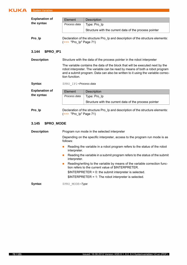
72 / 131
System Variables
Explanation of
the syntax
Pro_Ip Declaration of the structure Pro_Ip and description of the structure elements: (>>> "Pro_Ip" Page 71)
3.144 $PRO_IP1
Description Structure with the data of the process pointer in the robot interpreter
The variable contains the data of the block that will be executed next by the robot interpreter. The variable can be read by means of both a robot program and a submit program. Data can also be written to it using the variable correc-tion function.
Syntax $PRO_IP1=Process data
Explanation of
the syntax
Pro_Ip Declaration of the structure Pro_Ip and description of the structure elements: (>>> "Pro_Ip" Page 71)
3.145 $PRO_MODE
Description Program run mode in the selected interpreter
Depending on the specific interpreter, access to the program run mode is as follows:
Reading the variable in a robot program refers to the status of the robot interpreter.
Reading the variable in a submit program refers to the status of the submit interpreter.
Reading/writing to the variable by means of the variable correction func-tion refers to the current value of $INTERPRETER.
$INTERPRETER = 0: the submit interpreter is selected.
$INTERPRETER = 1: The robot interpreter is selected.
Syntax $PRO_MODE=Type
Element Description
Process data Type: Pro_Ip
Structure with the current data of the process pointer
Element Description
Process data Type: Pro_Ip
Structure with the current data of the process pointer
Issued: 16.08.2012 Version: KSS 8.1, 8.2, 8.3 Systemvariablen V2 en (PDF)

3 System variables
Explanation of
the syntax
3.146 $PRO_MODE0
Description Program run mode in the submit interpreter
The variable can be read by means of both a robot program and a submit pro-gram. Data can also be written to it using the variable correction function.
Syntax $PRO_MODE0=Type
Explanation of
the syntax
3.147 $PRO_MODE1
Description Program run mode in the robot interpreter
Element Description
Type Type: ENUM
#GO: The program is executed through to the end with-out stopping.
#MSTEP: Motion Step
The program is executed with a stop after each motion block and without advance processing.
#ISTEP: Incremental Step
The program is executed with a stop after each program line. Program lines that cannot be seen and blank lines are also taken into consideration. The program is exe-cuted without advance processing.
#BSTEP: Backward motion
This program run mode is automatically selected if the Start backwards key is pressed.
#PSTEP: Program Step
The program is executed step by step without advance processing. Subprograms are executed completely.
#CSTEP: Continuous Step
Approximate positioning points are executed with ad-vance processing, i.e. they are approximated. Exact po-sitioning points are executed without advance processing and with a stop after the motion instruction.
Default: #GO
Element Description
Type Type: ENUM
#GO: The program is executed through to the end with-out stopping.
#ISTEP: Incremental Step
The program is executed with a stop after each program line. Program lines that cannot be seen and blank lines are also taken into consideration. The program is exe-cuted without advance processing.
#PSTEP: Program Step
The program is executed step by step without advance processing. Subprograms are executed completely.
Default: #GO
Note: The program run modes #MSTEP, #BSTEP and #CSTEP are not available in the submit interpreter.
73 / 131Issued: 16.08.2012 Version: KSS 8.1, 8.2, 8.3 Systemvariablen V2 en (PDF)

74 / 131
System Variables
The variable can be read by means of both a robot program and a submit pro-gram. Data can also be written to it using the variable correction function.
Syntax $PRO_MODE1=Type
Explanation of
the syntax
(>>> 3.145 "$PRO_MODE" Page 72)
3.148 $PRO_NAME
Description Name of the program in the selected interpreter
Depending on the specific interpreter, access to the name is as follows:
Reading the variable in a robot program refers to the status of the robot interpreter.
Reading the variable in a submit program refers to the status of the submit interpreter.
It is not possible to write to the variable.
Syntax $PRO_NAME[]=Name
Explanation of
the syntax
3.149 $PRO_NAME0
Description Name of the program in the submit interpreter
Syntax $PRO_NAME1[]=Name
Explanation of
the syntax
3.150 $PRO_NAME1
Description Name of the program in the robot interpreter
Syntax $PRO_NAME1[]=Name
Explanation of
the syntax
Element Description
Name Type: CHAR
Program name: max. 24 characters
The variable is write-protected and can only be read.
Element Description
Name Type: CHAR
Program name: max. 24 characters
The variable is write-protected and can only be read.
Element Description
Name Type: CHAR
Program name: max. 24 characters
Issued: 16.08.2012 Version: KSS 8.1, 8.2, 8.3 Systemvariablen V2 en (PDF)

3 System variables
3.151 $PRO_STATE
Description Program state in the selected interpreter
Depending on the specific interpreter, access to the state is as follows:
Reading the variable in a robot program refers to the status of the robot interpreter.
Reading the variable in a submit program refers to the status of the submit interpreter.
It is not possible to write to the variable.
Syntax $PRO_STATE=State
Explanation of
the syntax
3.152 $PRO_STATE0
Description Program state in the submit interpreter
Syntax $PRO_STATE0=State
Explanation of
the syntax
(>>> 3.151 "$PRO_STATE" Page 75)
3.153 $PRO_STATE1
Description Program state in the robot interpreter
Syntax $PRO_STATE1=State
Explanation of
the syntax
(>>> 3.151 "$PRO_STATE" Page 75)
3.154 $RCV_INFO
Description Version identifier of the kernel system
Syntax $RCV_INFO[]="Identifier"
Explanation of
the syntax
Element Description
Type Type: ENUM
#P_FREE: Program is not selected.
#P_ACTIVE: Program is active.
#P_END: End of program has been reached.
#P_RESET: Program has been reset.
#P_STOP: Program has been stopped.
The variable is write-protected and can only be read.
The variable is write-protected and can only be read.
Element Description
Identifier Type: CHAR
Version identifier: max. 128 characters
75 / 131Issued: 16.08.2012 Version: KSS 8.1, 8.2, 8.3 Systemvariablen V2 en (PDF)

76 / 131
System Variables
Example
The identifier consists of the following components:
Kernel system version: KS V8.2.111
Name of author: krc1adm
Name of computer: deau1svr12pt-06
Date and time of compilation: 29 March 2012 at 10.34 a.m.
3.155 $RED_VEL
Description Reduction factor for program override in the advance run
Syntax $RED_VEL=Reduction factor
Explanation of
the syntax
3.156 $RED_VEL_C
Description Reduction factor for program override in the main run
Syntax $RED_VEL_C=Reduction factor
Explanation of
the syntax
3.157 $REVO_NUM
Description Counter for infinitely rotating axes
Syntax $REVO_NUM[Axis number]=Number
Explanation of
the syntax
3.158 $RINT_LIST
Description Structure with the data for a robot interrupt
$RCV_INFO[]="KS V8.2.111(krc1adm@deau1svr12pt-06) 1 Thu 29 Mar 2012 10:34:13 RELEASE"
Element Description
Reduction factor
Type: INT; unit: %
1 … 100
Default: 100
The variable is write-protected and can only be read.
Element Description
Reduction factor
Type: INT; unit: %
1 … 100
Default: 100
Element Description
Axis number Type: INT
1 … 6: Robot axis A1 ... A6
7 … 12: External axis E1 … E6
Number Type: INT
Number of revolutions
Issued: 16.08.2012 Version: KSS 8.1, 8.2, 8.3 Systemvariablen V2 en (PDF)

3 System variables
These data can be displayed via the variable correction function or by means of the diagnosis function in the main menu.
Precondition “Expert” user group
Procedure In the main menu, select Diagnosis > Interrupts.
Syntax $RINT_LIST[Index]={INT_PRIO Priority,INT_STATE State,INT_TYPE Type,PROG_LINE Line,PROG_NAME[] "Name"}
Explanation of
the syntax
3.159 $ROB_TIMER
Description Clock generator for measuring program runtimes
The variable is write-protected and counts in a cycle of 1 ms.
A maximum of 32 interrupts can be declared simultaneously in robot and submit programs and up to 16 interrupts can be active at the same time.
Further information about interrupt programming is contained in the “Operating and Programming Instructions for System Integrators”.
Element Description
Index Type: INT
Index of the interrupt
1 … 32
INT_PRIO Type: INT
Priority of the interrupt
1, 2, 4 … 39
81 …128
INT_STATE Bit array for interrupt states
Bit 0 = 1: Interrupt is declared and activated.
Bit 1 = 1: Interrupt is activated and enabled.
Bit 2 = 1: Interrupt is globally declared.
INT_TYPE Type: INT
Type of interrupt
0: Standard interrupt
1: Interrupt due to an EMERGENCY STOP ($EMSTOP)
2: Interrupt due to activation of the Fast Measurement inputs ($MEAS_PULSE)
3: Interrupt due to an error stop ($STOPMESS)
4: Interrupt due to a trigger (subprogram call)
PROG_LINE Type: INT
Line number of the robot program in which the interrupt is declared
PROG_NAME Type: CHAR
Directory and name of the robot program in which the inter-rupt is declared: max. 32 characters
77 / 131Issued: 16.08.2012 Version: KSS 8.1, 8.2, 8.3 Systemvariablen V2 en (PDF)

78 / 131
System Variables
Syntax $ROB_TIMER=Number
Explanation of
the syntax
3.160 $ROBNAME
Description User-defined robot name
The robot name entered in the robot data by the user is written to this variable.
Syntax $ROBNAME[]="Name"
Explanation of
the syntax
3.161 $ROBROOT_C
Description ROBROOT coordinate system in the main run
The ROBROOT coordinate system is a Cartesian coordinate system, which is always located at the robot base. The variable of structure type FRAME de-fines the current position of the robot in relation to the WORLD coordinate sys-tem.
X, Y, Z: Offset of the origin along the axes in [mm]
A, B, C: Rotational offset of the axis angles in [°]
3.162 $ROBROOT_KIN
Description Information about the external ROBROOT kinematic system
The variable contains the name of the external kinematic system and a list of the external axes contained in the transformation. The name and the external axes contained in the transformation are defined in the machine data, e.g. $ET1_NAME and $ET1_AX.
Syntax $ROBROOT_KIN[]="Information"
Explanation of
the syntax
$ROB_TIMER can only be assigned to an integer variable or com-pared with an integer variable. If a real variable is used, this results in values that are too high by a factor of around 100.
Element Description
Number Type: INT
Number of cycles
Element Description
Name Type: CHAR
Robot name: max. 50 characters
The variable is write-protected and can only be read.
Further information about the machine data can be found in the ma-chine data documentation.
Element Description
Information Type: CHAR
Name and external axes of the transformation: max. 29 characters
Issued: 16.08.2012 Version: KSS 8.1, 8.2, 8.3 Systemvariablen V2 en (PDF)

3 System variables
3.163 $ROBRUNTIME
Description Operating hours meter
The operating hours meter is running as long as the drives are switched on.
Syntax $ROBRUNTIME=Operating hours
Explanation of
the syntax
3.164 $ROBTRAFO
Description Robot name
The variable contains the robot name programmed on the RDC. This name must match the name of the coordinate transformation specified in the ma-chine data (variable $TRAFONAME in the file …R1\Mada\$machine.dat).
Syntax $ROBTRAFO[]="Name"
Explanation of
the syntax
3.165 $ROTSYS
Description Reference coordinate system for rotation in the advance run
The variable can be used to define the coordinate system in which the rotation (A, B, C) is executed in relative motions and in jogging.
Syntax $ROTSYS=Reference system
Explanation of
the syntax
3.166 $ROTSYS_C
Description Reference coordinate system for rotation in the main run
The variable contains the coordinate system in which the rotation (A, B, C) is currently executed in relative motions and in jogging.
Syntax $ROTSYS_C=Reference system
Element Description
Operating hours
Type: INT; unit: min
Element Description
Name Type: CHAR
Robot name: max. 32 characters
Element Description
Reference system
Type: ENUM
#AS_TRA: Rotation in the coordinate system $TRANS-SYS
#BASE: Rotation in the BASE coordinate system
#TCP: Rotation in the TOOL coordinate system
Default: #AS_TRA
The variable is write-protected and can only be read.
79 / 131Issued: 16.08.2012 Version: KSS 8.1, 8.2, 8.3 Systemvariablen V2 en (PDF)

80 / 131
System Variables
Explanation of
the syntax
3.167 $RUNTIME_DATA0
Description Structure with the runtime data of the submit interpreter
The variable can be used to display the runtime data via the variable correction function. The variable is write-protected.
Syntax $RUNTIME_DATA0={VISIBLE Visibility, NAME[] "Module", SNR Block number}
Explanation of
the syntax
3.168 $RUNTIME_DATA1
Description Structure with the runtime data of the robot interpreter
The variable can be used to display the runtime data via the variable correction function. The variable is write-protected.
Syntax $RUNTIME_DATA1={VISIBLE Visibility, NAME[] "Module", SNR Block number}
Element Description
Reference system
Type: ENUM
#AS_TRA: Rotation in the coordinate system $TRANS-SYS
#BASE: Rotation in the BASE coordinate system
#TCP: Rotation in the TOOL coordinate system
Default: #AS_TRA
This system variable is only available for reasons of compatibility. It is advisable to poll the runtime data via the variable $ERR.
Element Description
Visibility Type: BOOL
Visibility of the program in editor
TRUE: Program is visible.
FALSE: Program is not visible.
Module Type: CHAR
Name of the module in which the interpreter is situated: max. 32 characters
Block number Type: INT
Block number in which the interpreter is situated.
This system variable is only available for reasons of compatibility. It is advisable to poll the runtime data via the variable $ERR.
Issued: 16.08.2012 Version: KSS 8.1, 8.2, 8.3 Systemvariablen V2 en (PDF)

3 System variables
Explanation of
the syntax
3.169 $RUNTIME_ERROR0
Description Runtime error of the submit interpreter
Syntax $RUNTIME_ERROR0=State
Explanation of
the syntax
3.170 $RUNTIME_ERROR1
Description Runtime error of the robot interpreter
Syntax $RUNTIME_ERROR1=State
Explanation of
the syntax
3.171 $RVM
Description Resonance avoidance for approximated motions
If a motion is approximated and the next motion is a PTP motion with exact positioning, this can result in resonance vibrations of axis A1 if the distance be-tween the points is too small.
Element Description
Visibility Type: BOOL
Visibility of the program in editor
TRUE: Program is visible.
FALSE: Program is not visible.
Module Type: CHAR
Name of the module in which the interpreter is situated: max. 32 characters
Block number Type: INT
Block number in which the interpreter is situated.
This system variable is only available for reasons of compatibility. It is advisable to poll the runtime data via the variable $ERR.
Element Description
State Type: BOOL
TRUE: A runtime error has occurred.
FALSE: No runtime error has occurred.
Default: FALSE
This system variable is only available for reasons of compatibility. It is advisable to poll the runtime data via the variable $ERR.
Element Description
State Type: BOOL
TRUE: A runtime error has occurred.
FALSE: No runtime error has occurred.
Default: FALSE
81 / 131Issued: 16.08.2012 Version: KSS 8.1, 8.2, 8.3 Systemvariablen V2 en (PDF)

82 / 131
System Variables
If the variable $RVM is set to TRUE in the robot program, the motion time of the next motion sequence consisting of approximated motion and PTP motion with exact positioning is lengthened so that axis A1 no longer vibrates. The variable is then automatically reset to FALSE.
Syntax $RVM=State
Explanation of
the syntax
Example
Resonance avoidance does not take effect until the 2nd motion sequence in this program example. It has no effect on the 1st motion sequence because the exact positioning motion to which approximate positioning is carried out is a LIN motion.
3.172 $SAFETY_DRIVES_ENABLED
Description Drives enable of the safety controller
The variable indicates whether the safety controller has enabled the drives.
Syntax $SAFETY_DRIVES_ENABLED=State
Explanation of
the syntax
3.173 $SAFETY_SW
Description State of the enabling switches
Syntax $SAFETY_SW=State
This variable must not be used in the Submit interpreter or in an inter-rupt program.
Element Description
State Type: BOOL
TRUE: Resonance avoidance is active.
FALSE: Resonance avoidance is not active.
Default: FALSE
...$RVM=TRUE...PTP P5 C_PTPLIN P6...LIN P10 C_DISPTP P11...
Element Description
State Type: BOOL
TRUE: Drives are enabled.
FALSE: Drives are not enabled.
Default: FALSE
Issued: 16.08.2012 Version: KSS 8.1, 8.2, 8.3 Systemvariablen V2 en (PDF)

3 System variables
Explanation of
the syntax
3.174 $SAFE_FS_STATE
Description Status of the safety controller
The variable indicates whether the safety controller is running without errors. If the variable switches to TRUE, safe monitoring of the failsafe state has been activated and the safety controller is no longer operational.
Syntax $SAFE_FS_STATE=State
Explanation of
the syntax
3.175 $SAFE_IBN
Description Activation of Start-up mode
The variable is written to if Start-up mode is activated or deactivated via the main menu on the smartHMI.
Precondition Switching to Start-up mode is allowed: $SAFE_IBN_ALLOWED=TRUE
Syntax $SAFE_IBN=State
Explanation of
the syntax
3.176 $SAFE_IBN_ALLOWED
Description Switching to Start-up mode allowed?
The variable indicates whether switching to Start-up mode is currently al-lowed. Only if this is the case can Start-up mode be activated via the main menu on the smartHMI. The variable is write-protected.
Syntax $SAFE_IBN_ALLOWED=State
Element Description
State Type: ENUM
#PRESSED: An enabling switch is pressed (center po-sition).
#RELEASED: No enabling switch is pressed or an en-abling switch is fully pressed (panic position).
Element Description
State Type: BOOL
TRUE: The safety controller is not operable.
FALSE: The safety controller is running without errors.
Default: FALSE
Element Description
State Type: BOOL
TRUE: Start-up mode is active.
FALSE: Start-up mode is not active.
Default: FALSE
83 / 131Issued: 16.08.2012 Version: KSS 8.1, 8.2, 8.3 Systemvariablen V2 en (PDF)

84 / 131
System Variables
Explanation of
the syntax
3.177 $SEN_PINT
Description Exchange of integer values via a sensor interface
The sensor is used to transmit integer values to a sensor via an interface or to receive integer values from a sensor.
Syntax $SEN_PINT[Index]=Value
Explanation of
the syntax
3.178 $SEN_PINT_C
Description Exchange of integer values via a sensor interface
The sensor is used to transmit integer values to a sensor via an interface or to receive integer values from a sensor.
Syntax $SEN_PINT_C[Index]=Value
Explanation of
the syntax
3.179 $SEN_PREA
Description Exchange of real values via a sensor interface
The sensor is used to transmit real values to a sensor via an interface or to receive real values from a sensor.
Syntax $SEN_PREA[Index]=Value
Element Description
State Type: BOOL
TRUE: Start-up mode is allowed.
FALSE: Start-up mode is not allowed.
Default: FALSE
Element Description
Index Type: INT
Index of the variable
1 … 20
Value Type: INT
The variable $SEN_PINT_C has no relation to the main run. It is used in exactly the same way as the variable $SEN_PINT.
Element Description
Index Type: INT
Index of the variable
1 … 20
Value Type: INT
Issued: 16.08.2012 Version: KSS 8.1, 8.2, 8.3 Systemvariablen V2 en (PDF)

3 System variables
Explanation of
the syntax
3.180 $SEN_PREA_C
Description Exchange of real values via a sensor interface
The sensor is used to transmit real values to a sensor via an interface or to receive real values from a sensor.
Syntax $SEN_PREA_C[Index]=Value
Explanation of
the syntax
3.181 $SERVO_SIM
Description Simulation of the axis motions
Syntax $SERVO_SIM=State
Explanation of
the syntax
3.182 $SET_IO_SIZE
Description Number of digital inputs/outputs available
KUKA System Software 8.1: up to 4,096 digital I/Os
KUKA System Software 8.2 or higher: up to 8,192 digital I/Os
Syntax $SET_IO_SIZE=Number
Element Description
Index Type: INT
Index of the variable
1 … 20
Value Type: REAL
The variable $SEN_PREA_C has no relation to the main run. It is used in exactly the same way as the variable $SEN_PREA.
Element Description
Index Type: INT
Index of the variable
1 … 20
Value Type: REAL
Element Description
State Type: BOOL
TRUE: Simulation is active.
FALSE: No simulation active.
Default: FALSE
This system variable is only available for reasons of compatibility. The number of digital I/Os available can be monitored directly via the vari-ables $NUM_IN/$NUM_OUT.
The variable is write-protected and can only be read.
85 / 131Issued: 16.08.2012 Version: KSS 8.1, 8.2, 8.3 Systemvariablen V2 en (PDF)

86 / 131
System Variables
Explanation of
the syntax
3.183 $SINGUL_DIST
Description Standardized distance from the singularity
The variable specifies the standardized distance of the current robot position from the singularity in question. The variable is write-protected.
If the standardized distance at a robot position ≤1 and this position is used as a Cartesian end point of a PTP motion, the robot controller calculates the am-biguous axis angles according to the strategy defined with $SINGUL_POS[] in the machine data (variable in the file …R1\Mada\$machine.dat).
Syntax $SINGUL_DIST[Index]=Distance
Explanation of
the syntax
3.184 $SINT_LIST
Description Structure with the data for a submit interpreter
These data can be displayed via the variable correction function or by means of the diagnosis function in the main menu.
Precondition “Expert” user group
Procedure In the main menu, select Diagnosis > Interrupts.
Syntax $SINT_LIST[Index]={INT_PRIO Priority,INT_STATE State,INT_TYPE Type,PROG_LINE Line,PROG_NAME[] "Name"}
Element Description
Number Type: INT
1: 1 … 1,024
2: 1 … 2,048
4: 1 … 4,096
8: 1 … 8,192 (only for 8.2 or higher)
Default: 4
Element Description
Index Type: INT
Type of singularity position:
1: Overhead singularity $SINGUL_POS[1]
2: Extended position singularity $SINGUL_POS[2]
3: Wrist axis singularity $SINGUL_POS[3]
Distance Type: INT
Standardized distance from the specified singularity
A maximum of 32 interrupts can be declared simultaneously in robot and submit programs and up to 16 interrupts can be active at the same time.
Further information about interrupt programming is contained in the “Operating and Programming Instructions for System Integrators”.
Issued: 16.08.2012 Version: KSS 8.1, 8.2, 8.3 Systemvariablen V2 en (PDF)

3 System variables
Explanation of
the syntax
3.185 $SOFTPLCBOOL
Description Exchange of Boolean values between ProConOS and the robot controller
With the aid of function blocks of the Mulitprog library KrcExVarLib, individual or multiple values can be read from the array variable or written to the array variable.
Syntax $SOFTPLCBOOL[Index]=Value
Explanation of
the syntax
3.186 $SOFTPLCINT
Description Exchange of integer values between ProConOS and the robot controller
Element Description
Index Type: INT
Index of the interrupt
1 … 32
INT_PRIO Type: INT
Priority of the interrupt
1, 2, 4 … 39
81 …128
INT_STATE Bit array for interrupt states
Bit 0 = 1: Interrupt is declared and activated.
Bit 1 = 1: Interrupt is activated and enabled.
Bit 2 = 1: Interrupt is globally declared.
INT_TYPE Type: INT
Type of interrupt
0: Standard interrupt
1: Interrupt due to an EMERGENCY STOP ($EMSTOP)
2: Interrupt due to activation of the Fast Measurement inputs ($MEAS_PULSE)
3: Interrupt due to an error stop ($STOPMESS)
4: Interrupt due to a trigger (subprogram call)
PROG_LINE Type: INT
Line number of the submit program in which the interrupt is declared
PROG_NAME Type: CHAR
Directory and name of the submit program in which the interrupt is declared: max. 32 characters
Further information about the function blocks can be found in the KU-KA.PLC Multiprog documentation.
Element Description
Index Type: INT
Index of the variable
1 … 1024
Value Type: BOOL
87 / 131Issued: 16.08.2012 Version: KSS 8.1, 8.2, 8.3 Systemvariablen V2 en (PDF)

88 / 131
System Variables
With the aid of function blocks of the Mulitprog library KrcExVarLib, individual or multiple values can be read from the array variable or written to the array variable.
Syntax $SOFTPLCINT[Index]=Value
Explanation of
the syntax
3.187 $SOFTPLCREAL
Description Exchange of real values between ProConOS and the robot controller
With the aid of function blocks of the Mulitprog library KrcExVarLib, individual or multiple values can be read from the array variable or written to the array variable.
Syntax $SOFTPLCREAL[Index]=Value
Explanation of
the syntax
3.188 $SOFT_PLC_EVENT
Description Event tasks of the Soft PLC (ProConOS)
The variable can be used to call the mapped ProConOS events 0 to 7. The event tasks are triggered by a positive edge of the variable.
Syntax $SOFT_PLC_EVENT[Index]=State
Explanation of
the syntax
Further information about the function blocks can be found in the KU-KA.PLC Multiprog documentation.
Element Description
Index Type: INT
Index of the variable
1 … 1024
Value Type: INT
Further information about the function blocks can be found in the KU-KA.PLC Multiprog documentation.
Element Description
Index Type: INT
Index of the variable
1 … 1024
Value Type: REAL
Element Description
Index Type: INT
Index of the variable
1 … 8: ProConOS events 0 … 7 (= KRC event bits 0 … 7)
State Type: BOOL
TRUE: Event has been called.
FALSE: No event has been called.
Issued: 16.08.2012 Version: KSS 8.1, 8.2, 8.3 Systemvariablen V2 en (PDF)

3 System variables
3.189 $SPL_TECH
Description Function parameters of the spline function generator in the advance run
The variable can be used to program up to 6 spline function generators. A spline function generator is active in the case of SPLINE, SLIN and SCIRC and approximation of these spline motions. Only the main run variables are evaluated.
The function parameters can be modified in the robot program relative to the advance run.
Syntax $SPL_TECH[Index]=Parameters
Explanation of
the syntax
Spl_Tech STRUC Spl_Tech BOOL hand_weaving, REAL lim_full_hand_weaving, lim_no_hand_weaving, TECHMODE mo-de, TECHCLASS class, SPL_TECHSYS ref_sys, SPL_FCTCTRL fct-ctrl, SPL_TECHFCT fct, REAL fade_in, fade_out
The validity of the variable is reset after planning of a spline. If $SPL_TECH is displayed using the variable correction function, only the components of the next planned spline are visible.
Element Description
Index Type: INT
Number of the function generator:
1 … 6
Parameters Type: Spl_Tech
Definition of the function parameters and programming of the function evaluation
Element Description
hand_weaving
Activation of wrist axis weaving. This can prevent the robot from vibrating during weaving.
TRUE: Wrist axis weaving is activated.
FALSE: Wrist axis weaving is deactivated.
Default: FALSE
lim_full_hand_weaving
Limitation of the deviation from the programmed correction direction during wrist axis weaving. Only positive angles can be programmed. (Unit: °)
If the deviation is less than the angle lim_full_hand_weaving, only the wrist axis weav-ing correction is calculated.
If the deviation is greater than the angle lim_full_hand_weaving, but still less than lim_no_hand_weaving, both a wrist axis weaving correction and a standard correction are calculated.
If the deviation is greater than the angle lim_no_hand_weaving, only the standard correction is calculated.
lim_no_hand_weaving
mode Technology mode – type of function evaluation
#OFF: No function evaluation
#SINGLE: The function is evaluated once.
#CYCLE: The function is evaluated cyclically.
89 / 131Issued: 16.08.2012 Version: KSS 8.1, 8.2, 8.3 Systemvariablen V2 en (PDF)

90 / 131
System Variables
class Technology class – input size for the spline function gener-ator
#PATH: Input size is the arc length of a spline motion $DISTANCE (unit: mm)
#SYSTIME: Input size is the system time (unit: ms)
ref_sys Structure for definition of the reference coordinate system for geometric weaving of the spline function generator
STRUC Spl_Techsys TECHSYS sys, TECHANGLE angles, TECHGEOREF georef
Reference coordinate system selection (TECHSYS sys)
#WORLD
#BASE
#ROBROOT
#TCP
#TTS
Rotation of the reference coordinate system (TECHAN-GLE Angles; type: REAL; unit: °)
A, B, C: Angles about which the Z, Y and X axes of the reference coordinate system are rotated
Reference coordinate system axis used for weaving (TECHGEOREF Georef)
#NONE: Thermal weaving, not mechanical weav-ing, is carried out, i.e. the weave pattern is not exe-cuted; instead, only the function value is written to the variable $TECHVAL.
#X, #Y, #Z: During weaving, the TCP is offset by the function value in the direction of the X, Y or Z axis of the reference coordinate system.
#A, #B, #C: These components are not permissible.
fctctrl Control structure for the weave parameters of the spline function generator
STRUC Spl_Fctctrl BOOL adjust_wavelength, REAL scale_in, scale_out, offset_out
BOOL adjust_wavelength: The wavelength scale_in can be adapted to an integer multiple of the remaining path for a single spline block (= TRUE)
REAL scale_in: wavelength of the weave pattern
REAL scale_out: amplitude of the weave pattern
REAL offset_out: position of the weave pattern, e.g.:
$SPL_TECH[1].FCTCTRL.OFFSET_OUT = 0.0: The zero point of the weave motion is on the spline path.
Element Description
Issued: 16.08.2012 Version: KSS 8.1, 8.2, 8.3 Systemvariablen V2 en (PDF)

3 System variables
TechFct STRUC TechFct INT order, cpnum, TECHCPS cps1, cps2, cps3, cps4, cps5, SPL_TECH_BOUND bound_cond
fct Structure for defining the weave pattern for the spline func-tion generator
STRUC Spl_TechFct SPL_TECHFCT_MODE mode, TECHFCT Polynomial, SPL_FCTDEF fct_def, REAL blend_in, blend_out, phase_shift
ENUM for specification of the weave pattern type (SPL_TECHFCT_MODE mode)
#FCT_POLYNOMIAL: polynomial with control points
#FCT_SIN: asymmetrical sine (both half-waves can have different amplitudes and wavelengths)
Structure for defining the weave parameters for the weave pattern type #FCT_POLYNOMIAL (TECHFCT Polynomial)
(>>> "TechFct" Page 91)
Structure for defining the weave parameters for the weave pattern type #FCT_SIN (SPL_FCTDEF fct_def)
(>>> "Spl_FctDef" Page 92)
REAL blend_in: if the weave parameters are modified, it specifies the earliest fraction of the wavelength at which weaving deviates from the original pattern.
REAL blend_out: if the weave parameters are modified, it specifies the earliest fraction of the wavelength at which a transition to the new pattern is carried out.
REAL phase_shift: phase offset for execution of the weave pattern, e.g.:
$SPL_TECH[1].FCT.PHASE_SHIFT = 0.0: Weav-ing commences at the start of the spline path.
Note: The definition range and range of values of the func-tion fct are defined as follows:
Definition range: 0 … 1
Range of values: -1 … +1
fade_in Smoothing length for start of weaving and end of weaving
0.0 … 1.0
For a defined interval after the start and before the end, the specified weave pattern is multiplied by an S-shaped func-tion with values rising from 0 to 1.
The length of these intervals is defined using fade_in and fade_out. The longer the interval, the smoother the motion.
fade_out
Element Description
91 / 131Issued: 16.08.2012 Version: KSS 8.1, 8.2, 8.3 Systemvariablen V2 en (PDF)

92 / 131
System Variables
Spl_FctDef STRUC Spl_FctDef REAL amplitude1, amplitude2, wavelength_ratio
3.190 $SPL_TECH_C
Description Function parameters of the spline function generator in the main run
The variable can be used to program up to 6 spline function generators. A spline function generator is active in the case of SPLINE, SLIN and SCIRC and approximation of these spline motions. Only the main run variables are evaluated.
The function parameters can be modified relative to the main run by means of triggers, interrupts and the variable correction function. The modifications are
Element Description
order Degree of interpolation during spline evaluation
1: Weave pattern is defined by a polygon (sufficient in the case of thermal weaving only)
3: Weave pattern is defined by a cubic spline (required if mechanical weaving is carried out)
Note: If a polygon is sufficiently smooth for mechanical weaving due to utilization of the maximum number of con-trol points, degree of interpolation 1 is also allowed).
cpnum Total number of valid control points with reference to the following 4 control point structures
2 … 40
Note: No gaps are allowed between the valid control points.
cps1 List with control points 1 … 10 (type: REAL)
X1, Y1, … X10, Y10
cps2 List with control points 11 … 20 (type: REAL)
X1, Y1, … X10, Y10
cps3 List with control points 21 … 30 (type: REAL)
X1, Y1, … X10, Y10
cps4 List with control points 31 … 40 (type: REAL)
X1, Y1, … X10, Y10
cps5 This component cannot be written, as the number of con-trol points is limited to 40.
bound_cond Boundary conditions for a cubic spline (only relevant for degree of interpolation 3)
#CYCLIC: Cyclical boundary conditions (required in the case of mechanical weaving)
#NATURAL: Natural boundary conditions (sufficient in the case of thermal weaving only)
Element Description
amplitude1 Amplitude of the 1st half-wave of the asymmetrical sine (unit: dependent on the input size)
amplitude2 Amplitude of the 2nd half-wave of the asymmetrical sine (unit: dependent on the input size)
wavelength_ratio
Ratio of the wavelengths of the 2nd half-wave to the wave-length of the 1st half-wave
Issued: 16.08.2012 Version: KSS 8.1, 8.2, 8.3 Systemvariablen V2 en (PDF)

3 System variables
retained after a block change if these parameters have not been repro-grammed in the advance run.
Syntax $SPL_TECH_C[Index]=Parameters
Explanation of
the syntax
Spl_Tech Declaration of the structure and description of the structure elements: (>>> "Spl_Tech" Page 89)
Example
The weave amplitude SCALE_OUT changes with SLIN XP1 from 10 to 20. For SLIN XP2, also, the amplitude of 20 remains valid.
If, for SLIN XP2, the original weave amplitude of 10 is to apply again, this must be explicitly programmed:
3.191 $SPL_TECH_LINK
Description Shared function parameters of the spline function generators in the advance run
The variable of type Spl_Tech_Map can be used to link and unlink spline func-tion generators in the robot program, relative to the advance run.
Multidimensional function generators share the following function parameters:
The variable contains the currently used data of a spline function gen-erator. This has the following effect:
If the variable is modified, e.g. by a trigger, the change cannot be read immediately, but only after it has been accepted by the function genera-tor.
In the case of a multidimensional function generator, this refers to the shared data of the function generator acting as the master. (>>> 3.191 "$SPL_TECH_LINK" Page 93)
Element Description
Index Type: INT
Number of the function generator:
1 … 6
Parameters Type: Spl_Tech
Definition of the function parameters and programming of the function evaluation
$SPL_TECH[1].FCTCTRL.SCALE_OUT=10.0 TRIGGER WHEN PATH=-100 DELAY=0 DO $SPL_TECH_C[1].FCTCTRL.SCALE_OUT=20.0 SLIN XP1 SLIN XP2
$SPL_TECH[1].FCTCTRL.SCALE_OUT=10.0 TRIGGER WHEN PATH=-100 DELAY=0 DO $SPL_TECH_C[1].FCTCTRL.SCALE_OUT=20.0 SLIN XP1 $SPL_TECH[1].FCTCTRL.SCALE_OUT=10.0 SLIN XP2
Linked function generators ... Parameter
are activated together and deactivated together.
MODE
have a shared wavelength. FCTCTRL.SCALE_IN
FCTCTRL.ADJUST_WAVELENGTH
93 / 131Issued: 16.08.2012 Version: KSS 8.1, 8.2, 8.3 Systemvariablen V2 en (PDF)

94 / 131
System Variables
Spl_Tech_Map STRUC Spl_Tech_Map INT FG1, FG2, FG3, FG4, FG5, FG6
In order to link function generator x with function generator y, component FGx is assigned the integer value y. This means that function generator x uses the data of function generator y. Function generator y acts as the master. If x=y, function generator x is not linked.
Example
Function generators 1 to 3 are linked. Shared data are taken from function generator 1. Function generators 4 to 6 work without coupling.
Links across multiple stations, such as in the following example, are not per-missible:
If function generator 1 refers to function generator 2, function generator 2 can-not simultaneously refer to function generator 3.
3.192 $SPL_TECH_LINK_C
Description Shared function parameters of the spline function generators in the main run
The variable of type Spl_Tech_Map can be used to link and unlink spline func-tion generators by means of triggers or interrupts, relative to the main run.
Spl_Tech_Map Declaration of the structure and description of the linking: (>>> "Spl_Tech_Map" Page 94)
3.193 $SPL_TSYS
Description Position of the reference coordinate system of a spline function generator rel-ative to BASE
The variable contains the current position of the reference coordinate system of a function generator relative to the BASE coordinate system. The position is calculated for both active and inactive function generators in the spline in-terpolator. The variable is write-protected.
In the case of a PTP, LIN or CIRC motion, the variable loses its validity. This also applies if a program is reset or deselected.
require the same length of time to reach their full amplitude and to come back down from it.
FADE_IN
FADE_OUT
use the same input parameters, arc length or time.
CLASS
use the same reference coordinate system for the geometric correction.
REF_SYS.SYS
use wrist axis weaving together. HAND_WEAVING
HAND_WEAVING_MAX_ADJUST
Linked function generators ... Parameter
Wrist axis weaving is only possible for 2-dimensional function gener-ators.
$SPL_TECH_LINK={FG1 1, FG2 1, FG3 1, FG4 4, FG5 5, FG6 6}
$SPL_TECH_LINK={FG1 2, FG2 3, FG3 3, FG4 4, FG5 5, FG6 6}
It is only possible to add a new component to a multidimensional func-tion generator relative to the main run, or to remove it again, if the multidimensional function generator is not currently active.
Issued: 16.08.2012 Version: KSS 8.1, 8.2, 8.3 Systemvariablen V2 en (PDF)

3 System variables
Syntax $SPL_TSYS[Index]=Position
Explanation of
the syntax
3.194 $SPL_VEL_MODE
Description Motion profile for spline motions
In the robot program, the variable triggers an advance run stop.
Syntax $SPL_VEL_MODE=Motion profile
Explanation of
the syntax
3.195 $SPL_VEL_RESTR
Description Activation of Cartesian limits for spline motions with higher motion profile
The higher motion profile enables the robot controller already to take axis-spe-cific limits into consideration during path planning, and not wait until they are detected by monitoring functions during execution. All applications can gener-ally be executed faster with the higher motion profile.
The variable can be used to activate further Cartesian limits. In the robot pro-gram, the variable triggers an advance run stop.
Precondition The higher motion profile is active: $SPL_VEL_MODE=#OPT
Syntax $SPL_VEL_RESTR=Limits
Explanation of
the syntax
Element Description
Index Type: INT
Number of the function generator:
1 … 6
Position Type: FRAME
X, Y, Z: Offset of the origin along the axes in [mm]
A, B, C: Rotational offset of the axis angles in [°]
The system variable is available in KUKA System Software 8.2 and higher.
Element Description
Motion profile Type: ENUM
#OPT: Higher motion profile
This motion profile is activated by default when System Software 8.2 is installed for the first time.
#CART: Conventional motion profile
This motion profile is activated by default if a System Software version < 8.2 had previously been installed.
The system variable is available in KUKA System Software 8.2 and higher.
Element Description
Limits Type: Spl_Vel_Restr_Struc
The restrictions are deactivated by default. #ON activates them; #OFF deactivates them.
95 / 131Issued: 16.08.2012 Version: KSS 8.1, 8.2, 8.3 Systemvariablen V2 en (PDF)

96 / 131
System Variables
Spl_Vel_Restr
_Struc
STRUC Spl_Vel_Restr_Struc SW_ONOFF ori_vel, cart_acc, ori_acc, cart_jerk, ori_jerk, rob_acc, rob_jerk
Example
3.196 $SR_ACTIVETOOL
Description Number of the active safe tool
The variable indicates which tool is currently active on the safety controller. Only one safe tool may be active at any time. If interface X13 is used, this is always tool 1.
Syntax $SR_ACTIVETOOL=Number
Explanation of
the syntax
3.197 $SSB_ACTIVE
Description Structure with the IP addresses of the SSB-active robot controllers
Robot controllers are SSB-active if they have been enabled by the safety con-troller for the RoboTeam. SSB-inactive robot controllers receive the value ze-ro.
Syntax $SSB_ACTIVE=IP addresses
Explanation of
the syntax
Element Description
ori_vel Maximum orientation velocity
cart_acc Maximum Cartesian acceleration
ori_acc Maximum orientation acceleration
cart_jerk Maximum Cartesian jerk
ori_jerk Maximum orientation jerk
rob_acc Maximum acceleration of the robot axes
rob_jerk Maximum jerk of the robot axes
$SPL_VEL_RESTR={ORI_VEL=#OFF, CART_ACC=#ON, …, ROB_JERK=#OFF}
Only relevant if KUKA.SafeOperation is used.
Element Description
Number Type: INT
Number of the active safe tool:
0: no safe tool or multiple safe tools are selected.
1 … 16: safe tool 1 … 16 is active.
The system variable is available in KUKA System Software 8.2 and higher.
Element Description
IP addresses Type: ssb_active_t
STRUC ssb_active_t INT R1, R2, R3,… R14, R15, R16
Issued: 16.08.2012 Version: KSS 8.1, 8.2, 8.3 Systemvariablen V2 en (PDF)

3 System variables
3.198 $STOPMB_ID
Description Identification of the mailbox for stop messages
The variable is write-protected and required for reading the mailbox contents with the MBX_REC function.
Syntax $STOPMB_ID=Identifier
Explanation of
the syntax
3.199 $STOPNOAPROX
Description Message type in the case of “approximation not possible”
In modes T1 and T2, $STOPNOAPROX determines the message type for messages 1123, 1442 and 2920:
Either notification message that does not trigger a stop
Or acknowledgement message that triggers a stop
Syntax $STOPNOAPROX=State
Explanation of
the syntax
3.200 $SUPPRESS_ABS_ACCUR
Description Suppression of the positionally accurate robot model
The variable can be used to suppress the positionally accurate robot model briefly (for test purposes only).
Syntax $SUPPRESS_ABS_ACCUR=State
Explanation of
the syntax
3.201 $TECH
Description Function parameters of the function generator in the advance run
Element Description
Identifier Type: INT
Element Description
State Type: BOOL
TRUE
Operating mode T1 or T2: Acknowledgement mes-sage
Operating mode AUT or AUT EXT: Notification message
FALSE: Notification message only
Default: FALSE
Element Description
State Type: BOOL
TRUE: Positionally accurate robot model suppressed and thus not active
FALSE: No suppression, therefore positionally accurate robot model active
Default: FALSE
97 / 131Issued: 16.08.2012 Version: KSS 8.1, 8.2, 8.3 Systemvariablen V2 en (PDF)

98 / 131
System Variables
The variable can be used to program up to 6 function generators. The function generator is only active for CP motions; only the main run variables are eval-uated.
The function parameters can be modified in the robot program relative to the advance run.
Syntax $TECH[Index]=Parameter
Explanation of
the syntax
Tech STRUC Tech TECHMODE mode, TECHCLASS class, TECHFCTCTRL fctctrl, TECHFCT fct
Element Description
Index Type: INT
Number of the function generator
1 … 6
Parameter Type: Tech
Definition of the function parameters and programming of the function evaluation
Element Description
mode Technology mode – type of function evaluation
#OFF: No function evaluation
#SINGLE: The function is evaluated once.
#CYCLE: The function is evaluated cyclically.
class Technology class – input size for the function generator
#PATH: Input size is the arc length of a CP motion $DISTANCE (unit: mm)
#SYSTIME: Input size is the system time (unit: ms)
#VEL: Input size is the current path velocity $VEL_ACT (unit: m/s)
#SENSOR: Input size is the variable $TECHIN. De-pending on the input values, the robot performs a posi-tion correction.
#DATALINK: The input size is a correction frame that is written by the sensor task. Depending on the input val-ues, the robot performs a correction.
Issued: 16.08.2012 Version: KSS 8.1, 8.2, 8.3 Systemvariablen V2 en (PDF)

3 System variables
GeoRef
TechFct STRUC TechFct INT order, cpnum, TECHCPS cps1, cps2, cps3, cps4, cps5
fctctrl Control structure for the parameters of the function genera-tor
STRUC Fctctrl REAL scale_in, scale_out, offset_in, offset_out, TECHGEOREF georef
REAL scale_in: scales the definition range of the func-tion
REAL scale_out: scales the range of values of the func-tion
REAL offset_in: shifts the zero point of the definition range of the function
REAL offset_out: shifts the zero point of the range of values of the function
TECHGEOREF georef: ENUM for the geometric refer-ence of the technology function (>>> "GeoRef" Page 99)
Note: The offsets and scaling refer to the technology class, i.e. to the input size of the function generator.
fct Structure for defining the function parameters of the func-tion generator
(>>> "TechFct" Page 99)
Note: The definition range and range of values of the func-tion fct are defined as follows:
Definition range: 0 … 1
Range of values: -1 … +1
Element Description
Parameter Description
#NONE The programmed function is evaluated, but not carried out. The function value is written to the variable $TECHVAL.
Exception: If the technology class #SENSOR is used, the parameter has the effect that no function evaluation is car-ried out.
#X, #Y, #Z Axis of the reference coordinate system programmed by means of $TECHSYS and $TECHANGLE, used for weav-ing or sensor correction
During weaving or sensor correction, the TCP is offset by the function value in the direction of the X, Y or Z axis of the reference coordinate system.
#A, #B, #C Only relevant if the technology class #SENSOR is used!
Axis angle of the reference coordinate system pro-grammed by means of $TECHSYS and $TECHANGLE, used for sensor correction
The orientation of the TCP changes: rotation by the function value about the Z, Y or X axis of the reference coordinate system (always in the mathematically posi-tive direction)
99 / 131Issued: 16.08.2012 Version: KSS 8.1, 8.2, 8.3 Systemvariablen V2 en (PDF)

100 / 131
System Variables
Example Using a distance sensor, a correction of max. ±20 mm is to be made in the Z direction of the TTS. The analog sensor input delivers a voltage between -10 V and +10 V; this should be adjusted to 0 V (factor = 0.1; offset = 1.0).
Element Description
order Degree of interpolation during function evaluation
1: Function is defined by a polygon
cpnum Total number of valid control points with reference to the following 5 control point structures
2 … 50
Note: No gaps are allowed between the valid control points.
cps1 List with control points 1 … 10 (type: REAL)
X1, Y1, … X10, Y10
cps2 List with control points 11 … 20 (type: REAL)
X1, Y1, … X10, Y10
cps3 List with control points 21 … 30 (type: REAL)
X1, Y1, … X10, Y10
cps4 List with control points 31 … 40 (type: REAL)
X1, Y1, … X10, Y10
cps5 List with control points 41 … 50 (type: REAL)
X1, Y1, … X10, Y10
1 SIGNAL Correction $ANIN[2] 2 3 INTERRUPT DECL 1 WHEN $TECHVAL[1] > 20.0 DO Upper_Limit() 4 INTERRUPT DECL 2 WHEN $TECHVAL[1] < -20.0 DO Lower_Limit() 5 6 ANIN ON $TECHIN[1] = Factor * Correction + Offset 7 8 $TECHSYS = #TTS 9 $TECH[1].FTCCTRL.GEOREF = #Z 10 11 $TECH.CLASS = #SENSOR 12 13 $TECH[1].FCTCTRL.SCALE_IN = 2.0 14 $TECH[1].FCTCTRL.OFFSET_IN = 0.0 15 $TECH[1].FCTCTRL.SCALE_OUT = 2.0 16 $TECH[1].FCTCTRL.OFFSET_OUT = 0.0 17 $TECH[1].FCT.ORDER = 1 18 $TECH[1].FCT.CPNUM = 3 19 $TECH[1].FCT.CPS1.X1 = 0.0 20 $TECH[1].FCT.CPS1.Y1 = -1.0 21 $TECH[1].FCT.CPS1.X2 = 0.5 22 $TECH[1].FCT.CPS1.Y2 = 0.0 23 $TECH[1].FCT.CPS1.Y3 = 3.0 24 $TECHPAR[1,1] = 0.056 25 26 PTP Go_to_Workpiece 27 INTERRUPT ON 1 28 INTERRUPT ON 2 29 30 TECH[1].MODE = #CYCLE 31 LIN P1 C_DIS 32 LIN P2 C_DIS 33 LIN P3 34 35 TECH[1].MODE = #OFF 36 LIN_REL {X 0.0} 37 38 ANIN OFF Correction
Issued: 16.08.2012 Version: KSS 8.1, 8.2, 8.3 Systemvariablen V2 en (PDF)

3 System variables
3.202 $TECH_C
Description Function parameters of the function generator in the main run
The variable can be used to program up to 6 function generators. The function generator is only active for CP motions; only the main run variables are eval-uated.
The function parameters can be modified relative to the main run by means of triggers, interrupts and the variable correction function. The modifications are retained after a block change if these parameters have not been repro-grammed in the advance run.
Syntax $TECH_C[Index]=Parameter
Explanation of
the syntax
Tech Declaration of the structure TECH and description of the structure elements: (>>> "Tech" Page 98)
Line Description
1 Sensor at analog input 2
3, 4 Interrupts for monitoring the sensor correction
6 Cyclical reading of the analog input is started and the input value $TECHIN[1] is standardized to between 0.0 and 2.0.
8, 9 Correction in the Z direction of the TTS
13 Function generator with sensor correction functionality
14 … 23 Control parameters of the function generator
24 Smoothing constant (unit: s)
26 … 28 A motion is executed to a defined point in front of the work-piece and the interrupts for monitoring the sensor correction are activated.
30 Sensor correction is activated.
35 Sensor correction is deactivated.
36 The zero block is used to apply the advance run data to the main run data. This deactivates the function generator.
38 Cyclical reading of the analog input is started.
The variable contains the currently used data of a function generator. This has the following effect:
If the variable is modified, e.g. by a trigger, the change cannot be read immediately, but only after it has been accepted by the function genera-tor.
Element Description
Index Type: INT
Number of the function generator
1 … 6
Parameter Type: Tech
Definition of the function parameters and programming of the function evaluation
101 / 131Issued: 16.08.2012 Version: KSS 8.1, 8.2, 8.3 Systemvariablen V2 en (PDF)

102 / 131
System Variables
3.203 $TECHANGLE
Description Rotation of the reference coordinate system of a function generator in the ad-vance run
The variable can be used to define the orientation of the reference coordinate system defined by $TECHSYS and to modify it, relative to the advance run, in the robot program.
Syntax $TECHANGLE={A +z, B +y, C +x}
Explanation of
the syntax
3.204 $TECHANGLE_C
Description Rotation of the reference coordinate system of a function generator in the main run
The variable can be used to define the orientation of the reference coordinate system defined by $TECHSYS and to modify it, relative to the main run, by means of triggers, interrupts and the variable correction function. The modifi-cations are retained after a block change if the orientation has not been repro-grammed in the advance run.
Syntax $TECHANGLE_C={A +z, B +y, C +x}
Explanation of
the syntax
3.205 $TECHIN
Description Input value for the function generator
The variable forms the interface between the digital or analog sensor inputs of the robot controller and the function generator.
Data are written to this variable cyclically using the following statements:
Example of a sensor at analog input 2:
Example of a sensor at digital input 1 (entry in …\STEU\Mada\$ma-chine.dat):
This variable is not relevant for spline function generators.
Element Description
A Type: REAL; unit: °
Angle about which the Z, Y or X axis of the reference coor-dinate system is rotated (only positive direction permissi-ble)
B
C
This variable is not relevant for spline function generators.
Element Description
A Type: REAL; unit: °
Angle about which the Z, Y or X axis of the reference coor-dinate system is rotated (only positive direction permissi-ble)
B
C
SIGNAL Korrektur $ANIN[2] ANIN ON $TECHIN[1] = Faktor * Korrektur + Offset
Issued: 16.08.2012 Version: KSS 8.1, 8.2, 8.3 Systemvariablen V2 en (PDF)

3 System variables
It is not possible to write data directly to the variable from the robot program.
Precondition Technology class #SENSOR (>>> "Tech" Page 98)
Syntax $TECHIN[Index]=Input value
Explanation of
the syntax
3.206 $TECHPAR
Description Parameters of the function generator in the advance run
The variable can be used to define up to 10 input or output parameters of a function generator. If a parameter is used to output function generator states, the current parameter value can be found in the main run variable.
The variable can be modified in the robot program relative to the advance run.
Syntax $TECHPAR[Index 1,Index 2]=Parameter value
Explanation of
the syntax
3.207 $TECHPAR_C
Description Parameters of the function generator in the main run
The variable can be used to define up to 10 input or output parameters of a function generator. If a parameter is used to output function generator states, the current parameter value can be found in the main run variable.
The function parameters can be modified relative to the main run by means of triggers, interrupts and the variable correction function.
SIGNAL $DIGIN1 $IN[20]TO $IN[27] DECL DIGINCODE $DIGIN1CODE=#UNSIGNED DIGIN ON $TECHIN[2] = Faktor * $DIGIN1 + Offset
This variable is not relevant for spline function generators.
Element Description
Index Type: INT
Number of the function generator
1 … 6
Input value Type: REAL
Value loaded via the sensor input.
This variable is not relevant for spline function generators.
Element Description
Index 1 Type: INT
Number of the function generator
1 … 6
Index 2 Type: INT
Number of the parameter
1 … 10
Parameter value
Type: REAL
103 / 131Issued: 16.08.2012 Version: KSS 8.1, 8.2, 8.3 Systemvariablen V2 en (PDF)

104 / 131
System Variables
Syntax $TECHPAR_C[Index 1,Index 2]=Parameter value
Explanation of
the syntax
3.208 $TECHSYS
Description Reference coordinate system of a function generator in the advance run
The variable is used to define the reference coordinate system to which the function values calculated by the function generator refer.
The variable can be modified in the robot program relative to the advance run.
Syntax $TECHSYS=Coordinate system
Precondition GEOREF<>#NONE
(>>> "GeoRef" Page 99)
Explanation of
the syntax
3.209 $TECHSYS_C
Description Reference coordinate system of a function generator in the main run
The variable is used to define the reference coordinate system to which the function values calculated by the function generator refer.
The variable can be modified relative to the main run by means of triggers, in-terrupts and the variable correction function. The modification is retained after a block change if the reference coordinate system has not been repro-grammed in the advance run.
This variable is not relevant for spline function generators.
Element Description
Index 1 Type: INT
Number of the function generator
1 … 6
Index 2 Type: INT
Number of the parameter
1 … 10
Parameter value
Type: REAL
This variable is not relevant for spline function generators.
Element Description
Coordinate system
Type: ENUM
#BASE
#ROBROOT
#TCP
#TTS
#WORLD
Issued: 16.08.2012 Version: KSS 8.1, 8.2, 8.3 Systemvariablen V2 en (PDF)

3 System variables
Precondition GEOREF<>#NONE
(>>> "GeoRef" Page 99)
Syntax $TECHSYS_C=Coordinate system
Explanation of
the syntax
3.210 $TECHVAL
Description Function value of a function generator
The variable contains the result of the programmed function of a function gen-erator. This can be a conventionally programmed function generator or a spline function generator.
Syntax $TECHVAL[Index]=Result
Explanation of
the syntax
3.211 $TIMER
Description Timer for cycle time measurement
The timer can be set forwards or backwards to any freely selected value.
Syntax $TIMER[Index]=Time
Explanation of
the syntax
This variable is not relevant for spline function generators.
Element Description
Coordinate system
Type: ENUM
#BASE
#ROBROOT
#TCP
#TTS
#WORLD
If the function value $TECHVAL of a spline function generator is writ-ten to an analog output ANOUT, no negative DELAY is possible.
Element Description
Index Type: INT
Number of the function generator:
1 … 6
Result Type: REAL
Function value of the function generator
Element Description
Index Type: INT
Number of the timer
1 … 32
Time Type: INT; unit: ms
Default: 0
105 / 131Issued: 16.08.2012 Version: KSS 8.1, 8.2, 8.3 Systemvariablen V2 en (PDF)

106 / 131
System Variables
3.212 $TIMER_FLAG
Description Flag for the timer
The variable indicates whether the value of the timer is greater than or equal to zero.
$TIMER_FLAG can be used in interrupt conditions that are to be triggered af-ter a certain time has elapsed. If the corresponding $TIMER is started with a negative value, $TIMER_FLAG changes edge in the case of a zero passage.
Syntax $TIMER_FLAG[Index]=State
Explanation of
the syntax
3.213 $TIMER_STOP
Description Starting and stopping of the timer
The timer is started or stopped when the advance run pointer has reached the line with the timer.
Syntax $TIMER_STOP[Index]=State
Explanation of
the syntax
3.214 $TOOL
Description TOOL coordinate system in the advance run
The variable of structure type FRAME defines the setpoint position of the TOOL coordinate system in relation to the FLANGE coordinate system.
X, Y, Z: Offset of the origin along the axes in [mm]
A, B, C: Rotational offset of the axis angles in [°]
3.215 $TOOL_C
Description TOOL coordinate system in the main run
The variable of structure type FRAME defines the current actual position of the TOOL coordinate system in relation to the FLANGE coordinate system.
X, Y, Z: Offset of the origin along the axes in [mm]
A, B, C: Rotational offset of the axis angles in [°]
Element Description
Index Type: INT
Number of the timer
1 … 32
State Type: BOOL
TRUE: Value greater than zero
FALSE: Value equal to zero
Element Description
Index Type: INT
Number of the timer
1 … 32
State Type: BOOL
TRUE: Timer stopped
FALSE: Timer started
Issued: 16.08.2012 Version: KSS 8.1, 8.2, 8.3 Systemvariablen V2 en (PDF)

3 System variables
3.216 $TORQ_DIFF
Description Maximum torque deviation (force-induced torque)
During program execution, the $TORQ_DIFF values are calculated as the dif-ference between the setpoint torque and actual torque. These values are com-pared with the values from the previous program execution or with the default values. The highest value is saved.
If collision detection or torque monitoring is active, the system compares the values of $TORQ_DIFF with the saved values during the motion. The values are always calculated, even when collision detection or torque monitoring is deactivated.
Syntax $TORQ_DIFF[Axis number]=Deviation
Explanation of
the syntax
3.217 $TORQ_DIFF2
Description Maximum torque deviation (impact torque)
During program execution, the $TORQ_DIFF2 values are calculated as the difference between the setpoint torque and actual torque. These values are compared with the values from the previous program execution or with the de-fault values. The highest value is saved.
If collision detection or torque monitoring is active, the system compares the values of $TORQ_DIFF2 with the saved values during the motion. The values are always calculated, even when collision detection or torque monitoring is deactivated.
Syntax $TORQ_DIFF2[Axis number]=Deviation
Explanation of
the syntax
3.218 $TORQMON
Description Current factor for torque monitoring in program mode (force-induced torque)
If the robot collides with an object, the robot controller increases the axis torques in order to overcome the resistance. This can result in damage to the robot, tool or other objects.
The variable is write-protected and can only be read.
Element Description
Axis number Type: INT
1 … 6: Robot axis A1 ... A6
7 … 12: External axis E1 … E6
Deviation Type: INT; unit: %
Note: This value cannot be changed by the user.
Element Description
Axis number Type: INT
1 … 6: Robot axis A1 ... A6
7 … 12: External axis E1 … E6
Deviation Type: INT; unit: %
Note: This value cannot be changed by the user.
107 / 131Issued: 16.08.2012 Version: KSS 8.1, 8.2, 8.3 Systemvariablen V2 en (PDF)

108 / 131
System Variables
The variable $TORQMON contains the current tolerance range for the axis torques in program mode. This tolerance range is defined using the variable $TORQMON_DEF in the file …STEU\Mada\$custom.dat.
Syntax $TORQMON[Axis number]=Factor
Explanation of
the syntax
3.219 $TORQMON_COM
Description Current factor of torque monitoring in jogging
If the robot collides with an object, the robot controller increases the axis torques in order to overcome the resistance. This can result in damage to the robot, tool or other objects.
The variable $TORQMON_COM contains the current tolerance range for the axis torques in jogging. This tolerance range is defined using the variable $TORQMON_COM_DEF in the file …STEU\Mada\$custom.dat.
Syntax $TORQMON_COM[Axis number]=Factor
Explanation of
the syntax
3.220 $TORQUE_AXIS_ACT
Description Current motor torque of an axis
The displayed value is only relevant if the brakes are released. If the brakes are applied, it is virtually zero. (The state of the brakes can be displayed by means of the system variable $BRAKE_SIG. The value of $BRAKE_SIG is a bit array: bit 0 corresponds to A1, bit 6 corresponds to E1.)
The variable is write-protected. Its value is not dependent on the interpreter. In the robot program, the variable triggers an advance run stop.
Syntax $TORQUE_AXIS_ACT[Axis number]=Motor torque
Element Description
Axis number Type: INT
1 … 6: Robot axis A1 ... A6
7 … 12: External axis E1 … E6
Factor Type: INT; unit: %
Default: 200
Element Description
Axis number Type: INT
1 … 6: Robot axis A1 ... A6
7 … 12: External axis E1 … E6
Factor Type: INT; unit: %
Default: 200
The system variable for torque mode is available in KUKA System Software 8.2 and higher.
Issued: 16.08.2012 Version: KSS 8.1, 8.2, 8.3 Systemvariablen V2 en (PDF)

3 System variables
Explanation of
the syntax
3.221 $TORQUE_AXIS_LIMITS
Description Structure with the torque limits currently acting on an axis
The variable contains the currently active limits programmed with SET_TORQUE_LIMITS() for torque mode.
The variable is primarily intended for diagnosis via the variable correction func-tion or variable overview. In the robot program, the variable triggers an ad-vance run stop.
Syntax $TORQUE_AXIS_LIMITS[Axis number]=Limits
Explanation of
the syntax
TorqLimitParam STRUC TorqLimitParam REAL lower, upper, SW_ONOFF monitor, REAL max_vel, max_lag
Element Description
Axis number Type: INT
1 … 6: Robot axis A1 ... A6
7 … 12: External axis E1 … E6
Motor torque Type: REAL; unit: Nm (for linear axes: N)
The system variable for torque mode is available in KUKA System Software 8.2 and higher.
Element Description
Axis number Type: INT
1 … 6: Robot axis A1 ... A6
7 … 12: External axis E1 … E6
Limits Type: TorqLimitParam
Currently active torque limits
Element Description
lower Lower torque limit
Unit: Nm (for linear axes: N)
Default: -1E10 (i.e. unlimited)
upper Upper torque limit
Unit: Nm (for linear axes: N)
Default: 1E10 (i.e. unlimited)
monitor State of the regular monitoring functions
#ON: Activates the regular monitoring functions.
#OFF: Deactivates the regular monitoring functions. In-stead, the monitoring functions max_vel and max_lag are activated.
Default: #ON
109 / 131Issued: 16.08.2012 Version: KSS 8.1, 8.2, 8.3 Systemvariablen V2 en (PDF)

110 / 131
System Variables
Characteristics:
If there are currently no limits active, upper and lower remain non-initial-ized.
The component monitor is always initialized unless the axis does not ex-ist.
This is relevant, for example, in the case of 4-axis and 5-axis robots: if the entire array is displayed, the non-existent axes can be easily identified.
Non-existent external axes are simply not displayed when the entire array is displayed.
Max_vel and max_lag are non-initialized if monitor = #ON, as the reg-ular monitoring functions are active in this case.
If monitor = #OFF, the values of max_vel and max_lag are displayed, ir-respective of whether they have been set explicitly in the current program or whether the default values are being used.
3.222 $TORQUE_AXIS_MAX
Description Absolute maximum motor torque of an axis
The variable value is a constant and is provided by the motor driver. It corre-sponds to the maximum motor characteristic (converted to output coordinates) in which the functional relationship between velocity and achievable drive torque are represented by a partially linear function.
max_vel Maximum permissible actual velocity in torque mode (only relevant if the regular monitoring functions are deactivated)
Only a positive value may be programmed.
Unit: Degrees (for linear axes: mm)
Default value (valid for all operating modes): T1 jog velocity * internal safety factor
In T1, the maximum velocity with which jogging can be car-ried out is the default value, even if a higher value is pro-grammed.
Note: Only set a higher value than the default value if absolutely necessary.
max_lag Maximum permissible following error in torque mode (only relevant if the regular monitoring functions are deactivated)
Only a positive value may be programmed.
Unit: Degrees (for linear axes: mm)
Default value: 5 degrees (for linear axes: 100 mm)
Note: Only set a higher value than the default value if absolutely necessary.
The fact that certain components may remain non-initialized simpli-fies diagnosis for the user. If the variable is accessed via KRL, however, the robot controller may
regard the access as “invalid”. Recommendation: Check the state of the vari-able with VARSTATE() prior to access.
Element Description
The system variable for torque mode is available in KUKA System Software 8.2 and higher.
Issued: 16.08.2012 Version: KSS 8.1, 8.2, 8.3 Systemvariablen V2 en (PDF)

3 System variables
The variable is write-protected. Its value is not dependent on the interpreter.
Syntax $TORQUE_AXIS_MAX[Axis number]=Value
Explanation of
the syntax
3.223 $TORQUE_AXIS_MAX_0
Description Maximum permanent motor torque of an axis at velocity 0
The variable value is a constant and is provided by the motor driver. It does not normally correspond to the value of the motor characteristic at velocity 0, but is lower and already also takes into consideration derating effects of the converter.
The variable is write-protected. Its value is not dependent on the interpreter.
Syntax $TORQUE_AXIS_MAX_0[Axis number]=Value
Explanation of
the syntax
3.224 $TRACE
Description Parameters for the TRACE function of the oscilloscope
The variable of structure type TRACE is written in the case of data recording with the oscilloscope. The components of the aggregate can be used to start the recording via a program.
Syntax $TRACE={NAME[]"Name",MODE Mode,STATE State}
Explanation of
the syntax
Element Description
Axis number Type: INT
1 … 6: Robot axis A1 ... A6
7 … 12: External axis E1 … E6
Value Type: REAL; unit: Nm (for linear axes: N)
The value specifies an interval: from -value to +value.
The system variable for torque mode is available in KUKA System Software 8.2 and higher.
Element Description
Axis number Type: INT
1 … 6: Robot axis A1 ... A6
7 … 12: External axis E1 … E6
Value Type: REAL; unit: Nm (for linear axes: N)
The value specifies an interval: from -value to +value.
Element Description
Name Type: CHAR
Name of the TRC file: Maximum 7 characters
111 / 131Issued: 16.08.2012 Version: KSS 8.1, 8.2, 8.3 Systemvariablen V2 en (PDF)

112 / 131
System Variables
3.225 $TSYS
Description Position of the reference coordinate system of the function generator relative to BASE
The variable of structure type FRAME contains the current position of the ref-erence coordinate system of a function generator relative to the BASE coordi-nate system.
X, Y, Z: Offset of the origin along the axes in [mm]
A, B, C: Rotational offset of the axis angles in [°]
The variable is write-protected and is updated cyclically.
3.226 $VEL
Description Velocity of the TCP in the advance run
The variable of structure type CP contains the programmed Cartesian velocity for the following components:
CP: Path velocity in [m/s]
ORI1: Swivel velocity in [°/s]
ORI2: Rotational velocity in [°/s]
Limit values for the Cartesian velocity:
0.0 … $VEL_MA
The maximum Cartesian velocity $VEL_MA is defined in the machine da-ta.
If $VEL violates the limit values, the message Value assignment inadmissible is displayed. Program execution is stopped or the associated motion instruc-tion is not executed during jogging.
Example
Mode Type: ENUM
Recording mode
#T_START: Starts the recording.
#T_STOP: Stops the recording.
State Type: ENUM
State of the oscilloscope
#T_END: The oscilloscope does not record any data.
#TRIGGERED: The recording continues for the time de-fined by the trace length and trigger.
#T_WAIT: The oscilloscope is waiting for the trigger.
Element Description
This variable is not relevant for spline function generators.
Further information about the variable $VEL_MA can be found in the machine data documentation.
$VEL={CP 2.0,ORI1 300.0,ORI2 300.0}
Issued: 16.08.2012 Version: KSS 8.1, 8.2, 8.3 Systemvariablen V2 en (PDF)

3 System variables
3.227 $VEL_C
Description Velocity of the TCP in the main run
The variable of structure type CP contains the current Cartesian velocity for the following components:
CP: Path velocity in [m/s]
ORI1: Swivel velocity in [°/s]
ORI2: Rotational velocity in [°/s]
3.228 $VEL_ACT
Description Current path velocity
Syntax $VEL_ACT=Velocity
Explanation of
the syntax
3.229 $VEL_AXIS
Description Velocity of the robot axes in the advance run
The variable contains the programmed axis velocity as a percentage of the maximum axis velocity $VEL_AXIS_MA defined in the machine data (variable in the file …R1\Mada\$machine.dat).
Syntax $VEL_AXIS[Axis number]=Velocity
Explanation of
the syntax
3.230 $VEL_AXIS_C
Description Velocity of the robot axes in the main run
The variable contains the axis velocity of the motion currently being executed as a percentage of the maximum axis velocity $VEL_AXIS_MA defined in the machine data (variable in the file …R1\Mada\$machine.dat).
Syntax $VEL_AXIS_C[Axis number]=Velocity
The variable is write-protected and can only be read.
Element Description
Velocity Type: REAL; unit: m/s
0.0 … $VEL_MA.CP
Further information about the variable $VEL_MA can be found in the machine data documentation.
Element Description
Axis number Type: INT
1 … 6: Robot axis A1 ... A6
Velocity Type: INT; unit: %
1 … 100
The variable is write-protected and can only be read.
113 / 131Issued: 16.08.2012 Version: KSS 8.1, 8.2, 8.3 Systemvariablen V2 en (PDF)

114 / 131
System Variables
Explanation of
the syntax
3.231 $VEL_AXIS_ACT
Description Current motor speed
The variable contains the direction of rotation and the speed of the motor as a percentage of the maximum speed $VEL_AXIS_MA.
Syntax $VEL_AXIS_ACT[Axis number]=Speed
Explanation of
the syntax
3.232 $VEL_EXTAX
Description Velocity of the external axes in the advance run
The variable contains the programmed axis velocity as a percentage of the maximum axis velocity $VEL_AXIS_MA defined in the machine data (variable in the file …R1\Mada\$machine.dat).
Syntax $VEL_EXTAX[Axis number]=Velocity
Explanation of
the syntax
3.233 $VEL_EXTAX_C
Description Velocity of the external axes in the main run
The variable contains the axis velocity of the motion currently being executed as a percentage of the maximum axis velocity $VEL_AXIS_MA defined in the machine data (variable in the file …R1\Mada\$machine.dat).
Syntax $VEL_EXTAX_C[Axis number]=Velocity
Element Description
Axis number Type: INT
1 … 6: Robot axis A1 ... A6
Velocity Type: INT; unit: %
1 … 100
Further information about the variable $VEL_AXIS_MA can be found in the machine data documentation.
Element Description
Axis number Type: INT
1 … 6: Robot axis A1 ... A6
7 … 12: External axis E1 … E6
Speed Type: REAL; unit: %
-100.0 … +100.0
Element Description
Axis number Type: INT
1 … 6: External axis E1 … E6
Velocity Type: INT; unit: %
1 … 100
The variable is write-protected and can only be read.
Issued: 16.08.2012 Version: KSS 8.1, 8.2, 8.3 Systemvariablen V2 en (PDF)

3 System variables
Explanation of
the syntax
3.234 $WAIT_FOR
Description WAIT FOR statement at which the robot interpreter is currently waiting
Reading of the variable is only possible in a robot program. It cannot be read in a submit program. The variable is write-protected.
Syntax $WAIT_FOR[]="Statement"
Explanation of
the syntax
3.235 $WAIT_FOR0
Description WAIT FOR statement at which the submit interpreter is currently waiting
Syntax $WAIT_FOR0[]="Statement"
Explanation of
the syntax
Example WAIT FOR statement in the submit interpreter
The index resolution for $WAIT_FOR0 is always active. If $WAIT_FOR_ON0 == TRUE, i.e. the submit interpreter waits at the WAIT FOR statement, $WAIT_FOR0 = "WAIT FOR $IN[1026]".
3.236 $WAIT_FOR1
Description WAIT FOR statement at which the robot interpreter is currently waiting
Element Description
Axis number Type: INT
1 … 6: External axis E1 … E6
Velocity Type: INT; unit: %
1 … 100
Element Description
Statement Type: CHAR
WAIT FOR statement: max. 2,047 characters
The system variable is available in KUKA System Software 8.2 and higher.
The variable is write-protected and can only be read.
Element Description
Statement Type: CHAR
WAIT FOR statement: max. 2,047 characters
DEF submit() LOOP WAIT FOR $IN[1024 + 2] ENDLOOPEND
The system variable is available in KUKA System Software 8.2 and higher.
115 / 131Issued: 16.08.2012 Version: KSS 8.1, 8.2, 8.3 Systemvariablen V2 en (PDF)

116 / 131
System Variables
Syntax $WAIT_FOR1[]="Statement"
Explanation of
the syntax
Example WAIT FOR statement in the robot interpreter
The index resolution for $WAIT_FOR1 is always active. If $WAIT_FOR_ON1 == TRUE, i.e. the robot interpreter waits at the WAIT FOR statement, $WAIT_FOR1 = "WAIT FOR $IN[1026]".
3.237 $WAIT_FOR_INDEXRES
Description State of the index resolution with reference to the WAIT FOR statement
The variable can be read and changed via the variable correction function.
Syntax $WAIT_FOR_INDEXRES=State
Explanation of
the syntax
3.238 $WAIT_FOR_ON
Description State of the robot interpreter with reference to the WAIT FOR condition
Reading of the variable is only possible in a robot program. It cannot be read in a submit program.
Syntax $WAIT_FOR_ON=State
Explanation of
the syntax
3.239 $WAIT_FOR_ON0
Element Description
Statement Type: CHAR
WAIT FOR statement: max. 2,047 characters
DEF robot() LOOP WAIT FOR $IN[1024 + 2] ENDLOOPEND
Element Description
State Type: ENUM
#NO_RESOLUTION: Interpreter is waiting at a condi-tion that cannot be resolved.
#NO_WAIT: There is no wait condition active, and thus also no index resolution.
#WAIT_INDEX_RES: Interpreter is waiting for a condi-tion and the index resolution is active.
#WAIT_NO_INDEX_RES: Interpreter is waiting for a condition and the index resolution is not active.
Element Description
State Type: BOOL
TRUE: Interpreter is waiting.
FALSE: Interpreter is not waiting.
The system variable is available in KUKA System Software 8.2 and higher.
Issued: 16.08.2012 Version: KSS 8.1, 8.2, 8.3 Systemvariablen V2 en (PDF)

3 System variables
Description State of the submit interpreter with reference to the WAIT FOR condition
Syntax $WAIT_FOR_ON0=State
Explanation of
the syntax
3.240 $WAIT_FOR_ON1
Description State of the robot interpreter with reference to the WAIT FOR condition
Syntax $WAIT_FOR_ON1=State
Explanation of
the syntax
3.241 $WAIT_STATE
Description Interpreter flag for a wait condition
Syntax $WAIT_STATE=State
Explanation of
the syntax
The variable is write-protected and can only be read.
Element Description
State Type: BOOL
TRUE: Interpreter is waiting.
FALSE: Interpreter is not waiting.
The system variable is available in KUKA System Software 8.2 and higher.
The variable is write-protected and can only be read.
Element Description
State Type: BOOL
TRUE: Interpreter is waiting.
FALSE: Interpreter is not waiting.
The variable is write-protected and can only be read.
Element Description
State Type: ENUM
#NOT_WAITING : There is no wait condition active.
#WAIT_WORKSPACE: Robot is waiting for a work-space to be enabled.
#WAIT_PROGSYNC: When a PROGSYNC command is reached, the robot waits for all cooperating robots to reach this command (only relevant in RoboTeam).
#WAIT_REMOTECMD: Robot waits for a remote state-ment, e.g. via the network.
#WAIT_BOOL_EXPR: Robot waits for a Boolean ex-pression.
117 / 131Issued: 16.08.2012 Version: KSS 8.1, 8.2, 8.3 Systemvariablen V2 en (PDF)

118 / 131
System Variables
3.242 $WBOXDISABLE
Description State of workspace monitoring
Syntax $WBOXDISABLE=State
Explanation of
the syntax
3.243 $WORLD
Description WORLD coordinate system
The variable of structure type FRAME is write-protected and contains the ori-gin coordinate system for the ROBROOT and BASE coordinate system.
X, Y, Z: Offset of the origin along the axes in [mm]
A, B, C: Rotational offset of the axis angles in [°]
By definition, the variable components are set to zero.
Element Description
State Type: BOOL
TRUE: Monitoring is active.
FALSE: Monitoring is not active.
Default: FALSE
$WORLD={X 0.0, Y 0.0, Z 0.0, A 0.0, B 0.0, C 0.0}
The variable is write-protected and can only be read.
Issued: 16.08.2012 Version: KSS 8.1, 8.2, 8.3 Systemvariablen V2 en (PDF)

4 KUKA Service
4 KUKA Service
4.1 Requesting support
Introduction The KUKA Roboter GmbH documentation offers information on operation and provides assistance with troubleshooting. For further assistance, please con-tact your local KUKA subsidiary.
Information The following information is required for processing a support request:
Model and serial number of the robot
Model and serial number of the controller
Model and serial number of the linear unit (if applicable)
Model and serial number of the linear unit (if applicable)
Version of the KUKA System Software
Optional software or modifications
Archive of the software
For KUKA System Software V8: instead of a conventional archive, gener-ate the special data package for fault analysis (via KrcDiag).
Application used
Any external axes used
Description of the problem, duration and frequency of the fault
4.2 KUKA Customer Support
Availability KUKA Customer Support is available in many countries. Please do not hesi-tate to contact us if you have any questions.
Argentina Ruben Costantini S.A. (Agency)
Luis Angel Huergo 13 20
Parque Industrial
2400 San Francisco (CBA)
Argentina
Tel. +54 3564 421033
Fax +54 3564 428877
Australia Headland Machinery Pty. Ltd.
Victoria (Head Office & Showroom)
95 Highbury Road
Burwood
Victoria 31 25
Australia
Tel. +61 3 9244-3500
Fax +61 3 9244-3501
www.headland.com.au
119 / 131Issued: 16.08.2012 Version: KSS 8.1, 8.2, 8.3 Systemvariablen V2 en (PDF)
120 / 131
System Variables
Belgium KUKA Automatisering + Robots N.V.
Centrum Zuid 1031
3530 Houthalen
Belgium
Tel. +32 11 516160
Fax +32 11 526794
www.kuka.be
Brazil KUKA Roboter do Brasil Ltda.
Avenida Franz Liszt, 80
Parque Novo Mundo
Jd. Guançã
CEP 02151 900 São Paulo
SP Brazil
Tel. +55 11 69844900
Fax +55 11 62017883
Chile Robotec S.A. (Agency)
Santiago de Chile
Chile
Tel. +56 2 331-5951
Fax +56 2 331-5952
www.robotec.cl
China KUKA Automation Equipment (Shanghai) Co., Ltd.
Songjiang Industrial Zone
No. 388 Minshen Road
201612 Shanghai
China
Tel. +86 21 6787-1808
Fax +86 21 6787-1805
www.kuka.cn
Germany KUKA Roboter GmbH
Zugspitzstr. 140
86165 Augsburg
Germany
Tel. +49 821 797-4000
Fax +49 821 797-1616
www.kuka-roboter.de
Issued: 16.08.2012 Version: KSS 8.1, 8.2, 8.3 Systemvariablen V2 en (PDF)

4 KUKA Service
France KUKA Automatisme + Robotique SAS
Techvallée
6, Avenue du Parc
91140 Villebon S/Yvette
France
Tel. +33 1 6931660-0
Fax +33 1 6931660-1
www.kuka.fr
India KUKA Robotics India Pvt. Ltd.
Office Number-7, German Centre,
Level 12, Building No. - 9B
DLF Cyber City Phase III
122 002 Gurgaon
Haryana
India
Tel. +91 124 4635774
Fax +91 124 4635773
www.kuka.in
Italy KUKA Roboter Italia S.p.A.
Via Pavia 9/a - int.6
10098 Rivoli (TO)
Italy
Tel. +39 011 959-5013
Fax +39 011 959-5141
www.kuka.it
Japan KUKA Robotics Japan K.K.
Daiba Garden City Building 1F
2-3-5 Daiba, Minato-ku
Tokyo
135-0091
Japan
Tel. +81 3 6380-7311
Fax +81 3 6380-7312
Canada KUKA Robotics Canada Ltd.
6710 Maritz Drive - Unit 4
Mississauga
L5W 0A1
Ontario
Canada
Tel. +1 905 670-8600
Fax +1 905 670-8604
www.kuka-robotics.com/canada
121 / 131Issued: 16.08.2012 Version: KSS 8.1, 8.2, 8.3 Systemvariablen V2 en (PDF)

122 / 131
System Variables
Korea KUKA Robotics Korea Co. Ltd.
RIT Center 306, Gyeonggi Technopark
1271-11 Sa 3-dong, Sangnok-gu
Ansan City, Gyeonggi Do
426-901
Korea
Tel. +82 31 501-1451
Fax +82 31 501-1461
Malaysia KUKA Robot Automation Sdn Bhd
South East Asia Regional Office
No. 24, Jalan TPP 1/10
Taman Industri Puchong
47100 Puchong
Selangor
Malaysia
Tel. +60 3 8061-0613 or -0614
Fax +60 3 8061-7386
Mexico KUKA de México S. de R.L. de C.V.
Progreso #8
Col. Centro Industrial Puente de Vigas
Tlalnepantla de Baz
54020 Estado de México
Mexico
Tel. +52 55 5203-8407
Fax +52 55 5203-8148
www.kuka-robotics.com/mexico
Norway KUKA Sveiseanlegg + Roboter
Sentrumsvegen 5
2867 Hov
Norway
Tel. +47 61 18 91 30
Fax +47 61 18 62 00
Austria KUKA Roboter Austria GmbH
Vertriebsbüro Österreich
Regensburger Strasse 9/1
4020 Linz
Austria
Tel. +43 732 784752
Fax +43 732 793880
www.kuka-roboter.at
Issued: 16.08.2012 Version: KSS 8.1, 8.2, 8.3 Systemvariablen V2 en (PDF)

4 KUKA Service
Poland KUKA Roboter Austria GmbH
Spółka z ograniczoną odpowiedzialnością
Oddział w Polsce
Ul. Porcelanowa 10
40-246 Katowice
Poland
Tel. +48 327 30 32 13 or -14
Fax +48 327 30 32 26
Portugal KUKA Sistemas de Automatización S.A.
Rua do Alto da Guerra n° 50
Armazém 04
2910 011 Setúbal
Portugal
Tel. +351 265 729780
Fax +351 265 729782
Russia OOO KUKA Robotics Rus
Webnaja ul. 8A
107143 Moskau
Russia
Tel. +7 495 781-31-20
Fax +7 495 781-31-19
kuka-robotics.ru
Sweden KUKA Svetsanläggningar + Robotar AB
A. Odhners gata 15
421 30 Västra Frölunda
Sweden
Tel. +46 31 7266-200
Fax +46 31 7266-201
Switzerland KUKA Roboter Schweiz AG
Industriestr. 9
5432 Neuenhof
Switzerland
Tel. +41 44 74490-90
Fax +41 44 74490-91
www.kuka-roboter.ch
123 / 131Issued: 16.08.2012 Version: KSS 8.1, 8.2, 8.3 Systemvariablen V2 en (PDF)

124 / 131
System Variables
Spain KUKA Robots IBÉRICA, S.A.
Pol. Industrial
Torrent de la Pastera
Carrer del Bages s/n
08800 Vilanova i la Geltrú (Barcelona)
Spain
Tel. +34 93 8142-353
Fax +34 93 8142-950
www.kuka-e.com
South Africa Jendamark Automation LTD (Agency)
76a York Road
North End
6000 Port Elizabeth
South Africa
Tel. +27 41 391 4700
Fax +27 41 373 3869
www.jendamark.co.za
Taiwan KUKA Robot Automation Taiwan Co., Ltd.
No. 249 Pujong Road
Jungli City, Taoyuan County 320
Taiwan, R. O. C.
Tel. +886 3 4331988
Fax +886 3 4331948
www.kuka.com.tw
Thailand KUKA Robot Automation (M)SdnBhd
Thailand Office
c/o Maccall System Co. Ltd.
49/9-10 Soi Kingkaew 30 Kingkaew Road
Tt. Rachatheva, A. Bangpli
Samutprakarn
10540 Thailand
Tel. +66 2 7502737
Fax +66 2 6612355
www.kuka-roboter.de
Czech Republic KUKA Roboter Austria GmbH
Organisation Tschechien und Slowakei
Sezemická 2757/2
193 00 Praha
Horní Počernice
Czech Republic
Tel. +420 22 62 12 27 2
Fax +420 22 62 12 27 0
Issued: 16.08.2012 Version: KSS 8.1, 8.2, 8.3 Systemvariablen V2 en (PDF)

4 KUKA Service
Hungary KUKA Robotics Hungaria Kft.
Fö út 140
2335 Taksony
Hungary
Tel. +36 24 501609
Fax +36 24 477031
USA KUKA Robotics Corporation
51870 Shelby Parkway
Shelby Township
48315-1787
Michigan
USA
Tel. +1 866 873-5852
Fax +1 866 329-5852
www.kukarobotics.com
UK KUKA Automation + Robotics
Hereward Rise
Halesowen
B62 8AN
UK
Tel. +44 121 585-0800
Fax +44 121 585-0900
125 / 131Issued: 16.08.2012 Version: KSS 8.1, 8.2, 8.3 Systemvariablen V2 en (PDF)

126 / 131
System Variables
Issued: 16.08.2012 Version: KSS 8.1, 8.2, 8.3 Systemvariablen V2 en (PDF)

Index
Index
Symbols$ABS_ACCUR 13$ABS_RELOAD 13$ABS_UPDATE 13$ACC 14$ACC_AXIS 14$ACC_AXIS_C 15$ACC_C 14$ACC_CAR_ACT 15$ACC_CAR_LIMIT 15$ACC_CAR_MAX 16$ACC_CAR_STOP 15$ACC_EXTAX 16$ACC_EXTAX_C 16$ACC_MA 14$ACCU_STATE 17$ACT_ADVANCE 17$ACT_BASE 18$ACT_BASE_C 18$ACT_EX_AX 18$ACT_TOOL 19$ACT_TOOL_C 19$ADVANCE 18$ANIN 19$ANOUT 19$APO 20$APO_C 21$ASYNC_AXIS 21$ASYNC_EX_AX_DECOUPLE 22$ASYNC_FLT 23$ASYNC_STATE 23$AXIS_ACT 24$AXIS_ACT_MEAS 24$AXIS_BACK 24$AXIS_FOR 25$AXIS_INT 26$AXIS_MOT 26$AXIS_RET 26$B_IN 26$B_OUT 26$BASE 27$BASE_C 27$BASE_KIN 27$BRAKE_SIG 28, 108$CAB_FANSPEED 28$CIRC_MODE 28$CIRC_TYPE 31$CIRC_TYPE_C 31$CMD 31$CURR_ACT 32$CYCFLAG 32$DATA_EXT_OBJ1 33$DATA_EXT_OBJ2 33$DATA_INTEGRITY 33$DATAPATH 33$DATE 34$DEVICE 35$DIST_NEXT 35
$DISTANCE 35$DRIVES_ENABLE 35$ERR 35$EX_AX_ASYNC 22$EX_AX_IGNORE 37$FAST_MEAS_COUNT 37$FAST_MEAS_COUNT_RESET 37$FAST_MEAS_COUNT_TIME 37$FCT_CALL 39$FILTER 38$FILTER_C 38$FLAG 38$FOL_ERROR 39$GEAR_JERK 39$GEAR_JERK_C 40$HOLDING_TORQUE 40$HOLDING_TORQUE_MAND 41$HOME 41$I2T_OL 48$IN 42$INPOSITION 42$INTERPRETER 42, 70, 72$IOBUS_INFO 43$IOSIM_IN 43$IOSIM_OPT 44$IOSIM_OUT 45$IOSYS_IN_FALSE 46$IOSYS_IN_TRUE 46$IPO_MODE 47$IPO_MODE_C 47$IPO_WAIT_FOR 47$IPO_WAIT_FOR_ON 48$IPO_WAIT_STATE 48$IS_OFFICE_LITE 48$JERK 49$JERK_C 49$JERK_MA 49$KCP_CONNECT 50$KCP_IP 50$KCP_TYPE 50$KDO_ACT 50$KR_SERIALNO 51$LDC_ACTIVE 51$LDC_LOADED 51$LDC_RESULT 52$LK_MASTER 52$LK_SLAVES 52$LOAD 53$LOAD_A1 55$LOAD_A1_C 55$LOAD_A2 56$LOAD_A2_C 56$LOAD_A3 57$LOAD_A3_C 57$LOAD_C 54$MAMES_ACT 58$MASTERINGTEST_GROUP 59$MASTERINGTEST_REQ_INT 59
127 / 131Issued: 16.08.2012 Version: KSS 8.1, 8.2, 8.3 Systemvariablen V2 en (PDF)

128 / 131
System Variables
$MEAS_PULSE 60$MODE_OP 60$MOT_STOP 60$MOT_TEMP 61$MOUSE_ACT 61$MOUSE_DOM 61$MOUSE_ON 62$MOUSE_ROT 62$MOUSE_TRA 62$MOVE_BCO 62$NULLFRAME 62$NUM_IN 63$NUM_OUT 63$ORI_TYPE 63$ORI_TYPE_C 64$OUT 64$OUT_C 64$OV_ASYNC 65$OV_PRO 65$OV_ROB 66$PAL_MODE 66$PATHTIME 66$PC_FANSPEED 67$PINGCOOPKRC 67$POS_ACT 68$POS_ACT_MES 68$POS_BACK 68$POS_FOR 69$POS_INT 69$POS_RET 70$POWER_FAIL 70$POWEROFF_DELAYTIME 70$PRO_IP 70$PRO_IP0 71$PRO_IP1 72$PRO_MODE 72$PRO_MODE0 73$PRO_MODE1 73$PRO_NAME 74$PRO_NAME0 74$PRO_NAME1 74$PRO_STATE 75$PRO_STATE0 75$PRO_STATE1 75$RAISE_TIME 14, 15, 16$RCV_INFO 75$RED_VEL 76$RED_VEL_C 76$REVO_NUM 76$RINT_LIST 76$ROB_TIMER 77$ROBNAME 78$ROBROOT_C 78$ROBROOT_KIN 78$ROBRUNTIME 79$ROBTRAFO 79$ROTSYS 79$ROTSYS_C 79$RUNTIME_DATA0 80$RUNTIME_DATA1 80$RUNTIME_ERROR0 81
$RUNTIME_ERROR1 81$RVM 81$SAFE_FS_STATE 83$SAFE_IBN 83$SAFE_IBN_ALLOWED 83$SAFETY_DRIVES_ENABLED 82$SAFETY_SW 82$SEN_PINT 84$SEN_PINT_C 84$SEN_PREA 84$SEN_PREA_C 85$SERVO_SIM 85$SET_IO_SIZE 85$SINGUL_DIST 86$SINT_LIST 86$SOFT_PLC_EVENT 88$SOFTPLCBOOL 87$SOFTPLCINT 87$SOFTPLCREAL 88$SPL_TECH 89$SPL_TECH_C 92$SPL_TECH_LINK 93$SPL_TECH_LINK_C 94$SPL_TSYS 94$SPL_VEL_MODE 95$SPL_VEL_RESTR 95$SR_ACTIVETOOL 96$SSB_ACTIVE 96$STOPMB_ID 97$STOPNOAPROX 97$SUPPRESS_ABS_ACCUR 97$TECH 97$TECH_C 101$TECHANGLE 102$TECHANGLE_C 102$TECHIN 102$TECHPAR 103$TECHPAR_C 103$TECHSYS 104$TECHSYS_C 104$TECHVAL 105$TIMER 105$TIMER_FLAG 106$TIMER_STOP 106$TOOL 106$TOOL_C 106$TORQ_DIFF 107$TORQ_DIFF2 107$TORQMON 107$TORQMON_COM 108$TORQUE_AXIS_ACT 108$TORQUE_AXIS_LIMITS 109$TORQUE_AXIS_MAX 110$TORQUE_AXIS_MAX_0 111$TRACE 111$TSYS 112$VEL 112$VEL_ACT 113$VEL_AXIS 113$VEL_AXIS_ACT 114$VEL_AXIS_C 113
Issued: 16.08.2012 Version: KSS 8.1, 8.2, 8.3 Systemvariablen V2 en (PDF)

Index
$VEL_AXIS_MA 113, 114$VEL_C 113$VEL_EXTAX 114$VEL_EXTAX_C 114$VEL_MA 112$WAIT_FOR 115$WAIT_FOR_INDEXRES 116$WAIT_FOR_ON 116$WAIT_FOR_ON0 116$WAIT_FOR_ON1 117$WAIT_FOR0 115$WAIT_FOR1 115$WAIT_STATE 117$WBOXDISABLE 118$WORLD 118
CCenter of gravity 54CWRITE() 32, 39
DDocumentation, industrial robot 9
HHTTP 10
IInterpolation mode 47Introduction 9
KKCP 10KUKA Customer Support 119KUKA smartPAD 10
LLoads on the robot 53
MMass 54Mass moments of inertia 54Motion profile, c onventional 95Motion profile, higher 95
PPayloads 53
SSafety 11Safety instructions 9Service, KUKA Roboter 119Simulating inputs/outputs 45smartPAD 10SOAP 10Support request 119System variables 13
TTerms used 10Terms, used 10Training 9
TTS 10
VVelocity 65
WWarnings 9
129 / 131Issued: 16.08.2012 Version: KSS 8.1, 8.2, 8.3 Systemvariablen V2 en (PDF)

130 / 131
System Variables
Issued: 16.08.2012 Version: KSS 8.1, 8.2, 8.3 Systemvariablen V2 en (PDF)

131 / 131Issued: 16.08.2012 Version: KSS 8.1, 8.2, 8.3 Systemvariablen V2 en (PDF)
System Variables


![WEIHONG® WATERJET MACHINE’S MOTION CONTROL …¾ User can customize step-size under [Manual] interface. ¾ [System maintenance], user can maintain the system, and also can make](https://img.pdfslide.tips/doc/110x75/6103918f501bd113971b9da7/weihong-waterjet-machineas-motion-control-user-can-customize-step-size-under.jpg)


![Coaxial Noncontact Surface Compliance Distribution ... · measurement system can detect muscle contraction using acoustic radiation pressure in WHC 2013 [7]. This system measures](https://img.pdfslide.tips/doc/110x75/5f0e954a7e708231d43ff068/coaxial-noncontact-surface-compliance-distribution-measurement-system-can-detect.jpg)