Embed Size (px)
Citation preview
1
TABLE OF CONTENT FOR 400KV & 230KV SWITCHYARDS AND BOP ELECTRICAL AREAS FOR KKNPP 3 & 4
( EPC – E PACKAGE ) (Civil, Mechanical, Electrical, C & I Works and Services)
Sl. No
Section Name (As per CMM Format) Document Name Document No.
COVER PAGE
INSTRUCTION SHEET
1.0 SECTION - A GENERAL
1.1 Invitation to Tender & Tendering Conditions – Cover Page
1.2 Invitation to Tender & Tendering Conditions
1.3 Bidder Pre - Qualification Criteria for EPC – Electrical Package
2.0 SECTION - B GCC / SCC & APPLICABLE SAFETY GUIDES
2.1 General & Special Conditions of Contract - Cover / Separator Page
2.1.0 General Conditions of Contract - Cover Page
2.1.1 GENERAL CONDITIONS OF CONTRACT (GCC) FOR EPC GCC/EPC-4/REV-1
2.1.1.1
List of Annexure to EPC Form No. -
GCC/EPC-4/R-1 Annexure – A to J to GCC
2.1.1.2 AERB Safety Guidelines AERB/NRF/SG/IS-1 (Rev. 1)
2.1.1.3
Important Rules of Atomic energy (factories) rules, 1996 applicable to Engineering, Procurement & Construction contracts
2.1.1.4 NPCIL Model Rules for Labour Welfare
2.1.2 SPECIAL CONDITIONS OF CONTRACT (SCC)
2.1.2.0 Special Conditions of Contract - Cover Page / Separator Page
2.1.2.1 Special Conditions of the Contract - SCC
2.1.2.2 Special Conditions of Contract (SCC) – Payment Terms Annexure – A to SCC

2
Sl. No
Section Name (As per CMM Format) Document Name Document No.
2.1.2.2.1
Industrial Safety Clauses in Tender Documents for EPC Contracts issued by KKNPP Safety
Doc. No. PI / IS & F / 2016 / 01 / R0 Annexure – I to Annexure A of SCC
2.1.2.2.2 Project Instruction on HOUSE KEEPING for EPC Contracts Annexure – II to Annexure A of SCC
2.1.2.2.3 Project Instruction on PRESERVATION for EPC Contracts Annexure – III to Annexure A of SCC
2.1.2.3 Indicative Schedule for Execution of Works of EPC – Electrical Package
Annexure – B to SCC
I301.KK34.0.0.MP.PCA.P091
2.1.2.3.1 Indicative Network Schedule of Works in UAB + UAZ Building Annexure B – I
2.1.2.3.2 Indicative Network Schedule of Works in UAD Building Annexure B - II
2.1.2.3.3 Indicative Network Schedule of Works in 123 UBG + 0 4 UBG Building Annexure B - III
2.1.2.3.4 Indicative Network Schedule of Works in 0 UAC Building Annexure B - IV
2.1.2.3.5 Delivery schedule of Electrical-Package Equipments Annexure B - V
2.1.2.4
Special Conditions of Contract (SCC) - Loading and Penalty criteria for Transformers Annexure – C to SCC
2.1.2.5 ADDITIONAL SAFETY GUIDES
2.1.2.5.1
Earth resistance value and statutory provisions on earthing for construction, contractor & other facilities (infrastructures and electrical equipments etc.) of NPCIL projects/stations (not connected to permanent station earthing system) I&FS/2015/GL-02 – Rev. 1
2.1.2.5.2 Guidelines for use of Safety Helmets at KKNPP Site
2.1.2.5.3 Industrial Safety Guide on Pre-Job Briefing for Construction Works NPCIL / I & SF / 04700 / SG – 01 / R3
2.1.2.5.4
Technical Specifications for Construction Power Supply Distribution Boards (PDBs) & Extension Boards
3.0 SECTION - C TECHNICAL SPECIFICATIONS
OF STORES & DRAWINGS
Technical Specifications Of Stores & Drawings – Cover Page
3.1 SUB - SECTION
3.1
TECHNICAL REQUIREMENTS – SCOPE OF WORKS & SUPPLY -
Title Page

3
Sl. No
Section Name (As per CMM Format) Document Name Document No.
3.1.1
System Description & Scope of 400kV & 230kV Switchyards and BoP Electrical Areas for KKNPP 3 & 4 – EPC Package I02.KK34.0.0.TH.TS.PR004-Rev. 2
3.1.1.1
Scope Matrix to System Description and Scope of Electrical Area EPC Package Annexure – I to 3.1.1
3.1.1.2
Reference Document Matrix (RDM) for Electrical Area EPC Package Annexure – II to 3.1.1
3.1.1.3
List of applicable documents for the total scope of works Annexure – III to 3.1.1
3.1.1.4 Amendment to Applicable Documents Annexure – IV to 3.1.1
3.1.1.5 Seismic Inputs for Design of SSCs Annexure – V to 3.1.1
3.1.2
Scope of works – Civil Structural for Electrical Package I301.KK34.0.0.PR.TT.P022
3.1.3
Scope of works – Architecture for Electrical Area Package I301.KK34.0.0.PR.TT.P032
3.1.4
Scope of work / Supply for Material Handling Facilities of Electrical Package I301.KK34.0.0.PR.TT.WD001
3.1.5
Scope of work (Electrical) for Electrical Area Package
I02.KK34.0.0.PR.TT.PR.003 – Rev.R1
3.1.6 Scope of works – Technical Requirement of Instrumentation I02.KK34.0.0.AP.TT.PR002
3.1.7 Technical Compliance I301.KK34.0.0.MP.QN.PR001
3.1.8
Technical Confirmation list (Fire Fighting & Buried Pipelines) I301.KK34.0.0.PR.TT.P041
3.1.9
Technical Confirmation List (Civil – Structural) I301.KK34.0.0.MP.QN.PR020
3.2 SUB - SECTION – 3.2
PROJECT EXECUTION &
ASSURANCE PLAN
3.2.1
Project Execution & Assurance Plan – Project Procedure I301.KK34.0.0.MP.PCA.P011
3.2.2
Contract Completion for EPC Tender of KKNPP – 3 & 4 I301.KK34.0.0.MP.PCA.P130
3.2.3
Quality Management Systems Requirements from Contractors I301.KK34.0.0.MP.PCA.P151
3.2.4
Project Execution & Assurance Plan - Organisation I301.KK34.0.0.MP.PCA.P021
3.2.5
Project Execution & Assurance Plan - Communication I301.KK34.0.0.MP.PCA.P031
3.2.6
Project Execution & Assurance Plan - Coordination I301.KK34.0.0.MP.PCA.P041

4
Sl. No
Section Name (As per CMM Format) Document Name Document No.
3.2.7
Project Execution & Assurance Plan - Meetings I301.KK34.0.0.MP.PCA.P051
3.2.8
Project Execution & Assurance Plan - Reporting I301.KK34.0.0.MP.PCA.P061
3.2.9
Project Execution & Assurance Plan – Procurement and Sub-Contracting I301.KK34.0.0.MP.PCA.P071
3.2.10
Requirements for Construction, Supervision and management by Contractor I301.KK34.0.0.MP.PCA.P080
3.2.11
Project Planning, Scheduling, Monitoring and Control System for EPC Contracts of KKNPP- 3 & 4
I301.KK34.0.0.MP.PCA.P090 along with attachments listed in clause
3.2.11.1, 3.2.11.2 & 3.2.11.3
3.2.11.1
Project Schedule Hierarchy
Attachment No. 1 along with I301.KK34.0.0.MP.PCA.P090
3.2.11.2
Work Break Down Structure - Typical
Attachment No. 2 along with I301.KK34.0.0.MP.PCA.P090
3.2.11.3
Monthly Progress Report
Attachment No. 3 along with I301.KK34.0.0.MP.PCA.P090
3.3 SUB - SECTION
3.3
TECHNICAL REQUIREMENTS –
TECHNICAL SPECIFICATIONS
3.3
TECHNICAL REQUIREMENTS – TECHNICAL SPECIFICATIONS
TITLE SHEET
SUB - SECTION
3.3.1
CIVIL
3.3.1
Technical Specifications – Civil – Title Sheet -
3.3.1.1 Geotechnical Data for Electrical Area I301.KK34.0.0.GR.TS.WD023
3.3.1.2
Technical Specification for Construction of Civil Works I301.KK34.0.0.TH.TS.WD023
3.3.1.3 General Technical Requirements for Civil Design for Electrical Package I301.KK34.0.0.TH.TS.WD025
3.3.1.4
Technical Specification for Floor Finishing I301.KK34.0.AR.TS.WD031
3.3.1.5
Technical Specification for Steel / Al. Doors / Window & Ventilators I301.KK34.0.AR.TS.WD032
3.3.1.6 Technical Specification for Roofing I301.KK34.0.AR.TS.WD033
3.3.1.7
Technical Specification for Roof Treatment I301.KK34.0.AR.TS.WD034
3.3.1.8
Technical Specification for Fire check doors, Windows & Partitions I301.KK34.0.AR.TS.WD035

5
Sl. No
Section Name (As per CMM Format) Document Name Document No.
3.3.1.9
Technical Specification for Plastering & Pointing
I301.KK34.0.AR.TS.WD036
3.3.1.10
Technical Specification for White washing, Colour Washing, Distempering, Painting & Polishing I301.KK34.0.AR.TS.WD037
3.3.1.11 Technical Specification for Sanitary Fittings & Fixtures I301.KK34.0.AR.TS.WD038
3.3.1.12
Technical Specification for False Ceiling, False Flooring, under deck insulation and Partitioning I301.KK34.0.AR.TS.WD039
3.3.2 SUB SECTION -
3.3.2 TECHNICAL REQUIREMENTS –
TECHNICAL SPECIFICATIONS
MECHANICAL
3.3.2 Technical Specifications – Mechanical – Title Sheet
. 3.3.2.1
General Process Specification for KKNPP – 3 & 4 Project I301.KK34.0.0.AB.TS.PR001
3.3.2.2
Technical Specifications on Sewage Collection from Common access area, outdoor network, treatment plan & disposal of waste water (GQA) I301.KK34.0.GQA.TS.WD001
3.3.2.3
Technical Specifications For Storm and Ground Water Drain Collection From Various Areas, Outdoor Network To Storage Reservoir With Pumping Station 1301. KK34.0.GUD.TS.WD001
3.3.2.4
Technical Specifications for Fire Extinguishing (Water, Gas, Powder, Foam) System I301.KK34.0.SGA.TS.WD001
3.3.2.5 Technical Specifications for Domestic & Drinking Water System - GKD I02.KK34.0.GKD.TH.TS.PR001
3.3.2.6
Technical Specifications for Oil containing water sewage collection from various plant areas, Outdoor Network, Treatment Plant and disposal of waste water (GMA) I301.KK34.0.GMA.TS.WD001
3.3.2.7
Technical Specifications for Outdoor Buried Piping between various plant buildings I301.KK34.0.UZC.TS.WD001
3.3.2.8
Technical Specifications for Air Handling Units - HVAC I301 KK34 0 0 OW TS WD006
3.3.2.9 General guidelines for Piping I301.KK34.0.0.TH.TS.WD701
3.3.2.10 Piping Material Specifications I301.KK34.0.0.TH.TS.WD705
3.3.2.11 Valve Material Specifications I301.KK34.0.0.TH.TS.WD706
3.3.2.12
Technical Specification for fabrication and erection of piping I301.KK34.0.0.TH.TS.WD712
3.3.2.13
Technical Specification for inspection, flushing and hydro static testing of piping systems I301.KK34.0.0.TH.TS.WD713
3.3.2.14
Technical specification for non-destructive examination requirements of piping I208.KK36.0.0.TH.TS.PR016

6
Sl. No
Section Name (As per CMM Format) Document Name Document No.
3.3.2.15
Technical Specifications for Chain Pulley Block I301.KK34.0.0.MRR.TS.WD001
3.3.2.16
Technical Specifications for Electric Wire, Rope, Hoists I301.KK34.0.0.MRR.TS.WD002
3.3.2.17
Technical Specifications for EOT Crane I301.KK34.0.0.MRR.TS.WD003
3.3.2.18 Technical Specifications for Elevators I301.KK34.0.0.MRR.TS.WD004
3.3.2.19
Technical Specifications for Shop and Field Painting I301.KK34.0.0.TH.TS.WD122
3.3.2.20
Technical Specification for Ventilation and Air Conditioning Systems of NPCIL Design Scope of Plant Buildings I301.KK34.0.0.OW.TS.WD001
3.3.2.21 Technical Specifications for Air Filters I301.KK34.0.0.OW.TS.WD007
3.3.2.22
Technical Specifications for Ducting Systems (HVAC) I301.KK34.0.0.OW.TS.WD008
3.3.2.23 Technical Specifications of Dampers I301.KK34.0.0.OW.TS.WD009
3.3.2.24
Technical Specifications for Welding, Erection, Commissioning, Inspection and Testing (HVAC) I301.KK34.0.0.OW.TS.WD010
3.3.2.25
Technical Specifications of Centrifugal Fans I301.KK34.0.0.OW.TS.WD011
3.3.2.26
Technical Specifications of Axial Fans I301.KK34.0.0.OW.TS.WD012
3.3.2.27
Requirement for Equipment Erection for Balance of Plant (BOP) of KK unit 3&4 I01.KK36.0.0.TH.TS.WD717
3.3.2.28
Technical Specification for cold insulation of vessels, piping & equipments I301.KK34.0.0.TH.TS.WD703
3.3.2.29 Technical Specifications for Submersible Pumps I301.KK34.0.TH.TS.WD057
3.3.3 SUB - SECTION
C – 3.3.3 TECHNICAL REQUIREMENTS – TECHNICAL SPECIFICATIONS
ELECTRICAL
3.3.3.0
TECHNICAL SPECIFICATIONS – ELECTRICAL – Title Sheet
3.3.3.1
Job Specification – Electrical Part for 400kV & 230kV Switchyards and BoP Electrical Areas for KKNPP 3 & 4 – EPC Package I02.KK34.0.0.PR.TT.PR004
3.3.3.2
Technical Specifications for 400kV Gas Insulated Switchgear (GIS) & Gas Insulated Bus Duct (GIBD) I02.KK34.0.0.ET.TS.PR005
3.3.3.3
Technical Specifications for 230kV Gas Insulated Switchgear (GIS) & Gas Insulated Bus Duct (GIBD) I02.KK34.0.0.ET.TS.PR006
3.3.3.4
Technical Specifications for Control Metering, Relay Protection Panels for EHV Systems I02.KK34.0.0.ET.TS.PR008
Technical Specifications for 400kV Outdoor Switchyard I02.KK34.0.0.ET.TS.PR002

7
Sl. No
Section Name (As per CMM Format) Document Name Document No.
3.3.3.5
3.3.3.6
Technical Specifications for 230kV Outdoor Switchyard
I02.KK34.0.0.ET.TS.PR003
3.3.3.7
Technical Specifications for Oil Type Transformers & Reactors I02.KK34.0.0.ET.TS.PR024
3.3.3.8
Technical Specifications for 6kV Switchgear + Drawings I02.KK34.0.0.ET.TS.PR025
3.3.3.9
Technical Specifications for 415 V Switchgear I02.KK34.0.0.ET.TS.PR001
3.3.310
Technical Specifications for MV & LV Bus Ducts I02.KK34.0.0.ET.TS.PR028
3.3.3.11
Technical Specifications for 415 V MCCs I02.KK34.0.0.ET.TS.PR007
3.3.3.12
Technical Specifications for Dry type Auxiliary & Lighting transformer I02.KK34.0.0.ET.TS.PR023
3.3.3.13
Technical Specifications for MV Motors I02.KK34.0.0.ET.TS.PR021
3.3.3.14
Technical Specifications for LV Motors I02.KK34.0.0.ET.TS.PR022
3.3.3.15
Technical Specifications for Rectifier, Inverters, Direct Current Distribution Boards (DCDBs) & Alternating Current Distribution Boards (ACDBs), Spare Cell Chargers & Load Banks of Common Station Systems / BOP Areas I02.KK34.0.0.ET.TS.PR030
3.3.3.16
Technical Specification for Lead Acid Batteries I02.KK34.0.0.ET.TS.PR029
3.3.3.17
Technical Specification for Neutral Grounding Resistors (NGR) I02.KK34.0.0.ET.TS.PR032
3.3.3.18
Technical Specifications for Numerical Relays I02.KK34.0.0.ET.TS.PR026
3.3.3.19 Technical Specifications for Lighting Systems I02.KK34.0.0.ET.TS.PR004
3.3.3.20 Technical Specifications for Cable Systems & Cabling Guideline I02.KK34.0.0.ET.TT.PR001
3.3.3.21 Technical Specifications for Grounding and Lightning Protection Systems I02.KK34.0.0.ET.TT.PR002
3.3.3.22 Technical Specifications for SCADA I02.KK34.0.0.ET.TS.PR027
3.3.3.23
Technical Specifications for Cable Carrier System I02.KK34.0.0.ET.TS.PR009
3.3.3.24
Technical Specifications for MV Power Cables, Cable Type – PvVng (A) - LS I02.KK34.0.0.ET.TS.PR010
3.3.3.25
Technical Specifications for LV Power Cables, Cable Type – VVGng – FRLS & VVGEng - FRLS I02.KK34.0.0.ET.TS.PR011

8
Sl. No
Section Name (As per CMM Format) Document Name Document No.
3.3.3.26
Technical Specifications for LV Power Cables, Cable Type – VVGng –LS & VVGEng - LS I02.KK34.0.0.ET.TS.PR012
3.3.3.27
Technical Specifications for Control Cables, Cable Type – KVVGng – FRLS & KVVGEng - FRLS I02.KK34.0.0.ET.TS.PR013
3.3.3.28
Technical Specifications for Control Cables, Cable Type – KVVGng – LS & KVVGEng - LS I02.KK34.0.0.ET.TS.PR014
3.3.3.29
Technical Specifications for Fire Barrier & Fire Resistant Coating I02.KK34.0.0.ET.TS.PR015
3.3.3.30
Technical Specifications for Fibre Optic Cable & Accessories I02.KK34.0.0.ET.TS.PR031
3.3.3.31
Technical Specification for GS Rods, GS Flats, GS Junction Boxes and GS Test Link Boxes I02.KK34.0.0.ET.TS.PR016
3.3.3.32
Technical specification for Copper Bare Conductors up to 70 Sq. mm I02.KK34.0.0.ET.TS.PR017
3.3.3.33
Technical specification for Copper Bare Conductors up to 400 Sq. mm I02.KK34.0.0.ET.TS.PR018
3.3.3.34
Technical Specifications for Glass Reinforced Polyester (GRP) Cable Trays I02.KK34.0.0.ET.TS.PR019
3.3.3.35 Technical Specifications for Wire Mesh Cable Trays I02.KK34.0.0.ET.TS.PR020
3.3.3.36 Technical Specifications for Hazardous Area Equipment I301.KK34.0.0.ET.TS.PR032
3.3.3.37
Technical Specifications for 230kV Tie Line between KKNPP Unit – 1 & 2 and 3 &4 I02.KK34.0.0.ET.TS.PR034
3.3.4 SUB - SECTION
C – 3.3.4 TECHNICAL REQUIREMENTS – TECHNICAL SPECIFICATIONS
INSTRUMENTATION & CONTROL
3.3.4.0
TECHNICAL SPECIFICATIONS
– I & C – Title Sheet
3.3.4.1
Technical Requirements of Instrumentation I02.KK34.0.0.AP.TT.PR001_R0
3.3.4.2 Technical Requirements of Instruments I02.KK34.0.0.AP.TU.PR001_R1
3.3.4.3
Technical Specifications of Hydrogen Detector I02.KK34.0.0.AT.TS.PR002_R0
3.4 SUB SECTION -
3.4 TECHNICAL REQUIREMENTS –
DATA SHEETS
3.4.1 3.4.1
MECHANICAL
3.4.1.0 Mechanical Data Sheets – Title Sheet
3.4.1.1 Data sheet for Fire Fighting Systems I301.KK34.0.0.SGA.AB.DS.WD100

9
Sl. No
Section Name (As per CMM Format) Document Name Document No.
3.4.1.2
Data Sheet for Ventilation and Air-Conditioning Systems of NPCIL designed scope of Plant Buildings I301.KK34.0.0.OW.DS.WD001
3.4.1.3
Typical Data Sheet for Rotating Pumps I301.KK34.0.0.AB.DS.WD500
3.4.2 SUB - SECTION
3.4.2 TECHNICAL REQUIREMENTS –
DATA SHEETS
3.4.2.0
ELECTRICAL – Title Sheet
3.4.2.1
Data Sheet for 400kV Gas Insulated Switchgear (GIS) & Gas Insulated Bus Duct (GIBD) I02.KK34.0.0.ET.DS.PR005
3.4.2.2
Data Sheet for 230kV Gas Insulated Switchgear (GIS) & Gas Insulated Bus Duct (GIBD) I02.KK34.0.0.ET.DS.PR006
3.4.2.3
Data Sheet for Common Station Auxiliary Transformer (CSAT) I02.KK34.0.0.ET.DS.PR019
3.4.2.4
Data Sheet for Shunt Reactors I02.KK34.0.0.ET.DS.PR022
3.4.2.5
Data Sheet for Reserve Auxiliary Transformers (RATs) I02.KK34.0.0.ET.DS.PR021
3.4.2.6
Data Sheet for 400kV Outdoor Switchyard I02.KK34.0.0.ET.DS.PR002
3.4.2.7
Data Sheet for 230kV Outdoor Switchyard I02.KK34.0.0.ET.DS.PR003
3.4.2.8 Data Sheets for 6kV Switchgear I02.KK34.0.0.ET.DS.PR023
3.4.2.9 Data Sheets for 415 V Switchgear I02.KK34.0.0.ET.DS.PR001
3.4.2.10 Data Sheet for 415 V MCCs I02.KK34.0.0.ET.DS.PR007
3.4.2.11
Data Sheet for Dry Type Auxiliary & Lighting Transformer I02.KK34.0.0.ET.DS.PR018
3.4.2.12 Data sheet for MV Motors I02.KK34.0.0.ET.DS.PR016
3.4.2.13 Data sheet for LV Motors I02.KK34.0.0.ET.DS.PR017
3.4.2.14
Data Sheet for Rectifiers, Inverters, Direct Current Distribution Boards (DCDBs) & Alternating Current Distribution Boards (ACDBs), Spare Cell Chargers & Load Banks of Common Station Systems / BOP Areas I02.KK34.0.0.ET.DS.PR027
3.4.2.15
Data sheet for Lead Acid Batteries I02.KK34.0.0.ET.DS.PR026
3.4.2.16
Data Sheet for Neutral Grounding Resistor I02.KK34.0.0.ET.DS.PR015
3.4.2.17 Data Sheet for Numerical Relays I02.KK34.0.0.ET.DS.PR024
3.4.2.18 Data Sheet for MV Bus Duct I02.KK34.0.0.ET.DS.PR025
3.4.2.19
Data Sheet for LV Bus Duct I02.KK34.0.0.ET.DS.PR029

10
Sl. No
Section Name (As per CMM Format) Document Name Document No.
3.4.2.20 Data Sheet for Fibre Optic Cable & Accessories I02.KK34.0.0.ET.DS.PR028
3.4.2.21 Data Sheet for Lighting Fixtures I02.KK34.0.0.ET.DS.PR004
3.4.2.22 Data Sheet for 415 LDB I02.KK34.0.0.ET.DS.PR030
3.4.2.23
Data Sheet for MV Power Cables, Cable types – PvVng (A) - LS I02.KK34.0.0.ET.DS.PR008
3.4.2.24
Data Sheet for LV Power Cables, Cable types – VVGng – FRLS & VVGEng - FRLS
I02.KK34.0.0.ET.DS.PR009
3.4.2.25 Data Sheet for LV Power Cables, Cable types – VVGng – LS & VVGEng - LS
I02.KK34.0.0.ET.DS.PR010
3.4.2.26
Data Sheet for Control Cables, Cable types – KVVGng – FRLS & KVVGEng - FRLS
I02.KK34.0.0.ET.DS.PR011
3.4.2.27 Data Sheet for Control Cables, Cable types – KVVGng – LS & KVVGEng - LS I02.KK34.0.0.ET.DS.PR012
3.4.2.28
Data Sheet for Copper Bare Conductor up to 70 sq. mm I02.KK34.0.0.ET.DS.PR013
3.4.2.29
Data Sheet for Copper Bare Conductor up to 400 sq. mm I02.KK34.0.0.ET.DS.PR014
3.4.3 SUB - SECTION
C – 3.4.3 TECHNICAL REQUIREMENTS –
DATA SHEETS
3.4.3.0
INSTRUMENTATION – Title Sheet
3.4.3.1 Data Sheets of Instrumentation I301.KK34.0.0.AP.DS.PR001
3.5 SUB - SECTION
3.5
TECHNICAL REQUIREMENTS –
MANDATORY SPARES
3.5.1
MANDATORY SPARES MECHANICAL
3.5.1.0
MANDATORY SPARES MECHANICAL
Title Sheet
3.5.1.1 Mandatory Spares for Rotating Equipments I301.KK34.0.0.PR.MS.050
3.5.1.2
Mandatory Spare Parts for HVAC, Material Handling for Electrical Area Package I301.KK34.0.0.PR.MS.WD001
3.5.1.3
Mandatory Spare Parts (Fire Fighting & Buried Pipelines) I301.KK34.0.0.PR.TT.P031
3.5.2 MANDATORY SPARES
ELECTRICAL
3.5.2.0
MANDATORY SPARES ELECTRICAL
Title Sheet
3.5.2.1
Mandatory Spares for 400kV & 230kV Switchyards and BoP Electrical Area Package of KKNPP Unit – 3 & 4 I02.KK34.0.0.TH.ZI.PR002

11
Sl. No
Section Name (As per CMM Format) Document Name Document No.
3.5.3 MANDATORY SPARES
INSTRUMENTATION
3.5.3.0
MANDATORY SPARES INSTRUMENTATION
Title Sheet
3.5.3.1 Mandatory Spares for Instrumentation I02.KK34.0.0.AP.ZI.PR001_R0
3.6 SUB - SECTION
3.6
TECHNICAL REQUIREMENTS – VDR – VENDOR DRAWINGS AND
DOCUMENTS FOR OWNER REVIEW
3.6.0
VENDOR DRAWINGS AND DOCUMENTS FOR OWNER REVIEW
Title Sheet
3.6.1
Documents/drawings Preparation & Submission I301.KK34.0.0.PR.VDR.P001
3.6.2
Documents for NPCIL (Owners / PMC) Review – Civil Structural I301.KK34.0.0.PR.VDR.P020
3.6.3
Vendor Data Requirements (Architecture) for Electrical Area I301.KK34.0.0.PR.VDR.P032
3.6.4
Vendor Data Requirement (Buried Pipeline & Fire Fighting System) I301.KK34.0.0.PR.TT.P051
3.6.5
Vendor Data Requirements for Static Equipment I301.KK36.0.0.PR.VDR.P041
3.6.6
Vendor Data Requirements for Rotating Equipment I301.KK34.0.0.PR.VDR.P050
3.6.7
Vendor Data Requirements for Piping I301.KK34.0.0.PR.VDR.P070
3.6.8
Vendor Data Requirements for Electrical Equipments of 400kV & 230kV Switchyards and BoP Electrical Areas of KKNPP – 3 & 4 I02.KK34.0.0.TH.REP.PR002
3.6.9
Vendor Data Requirements for Instrumentation I02.KK34.0.0.AP.REP.PR001
3.7 SUB - SECTION
3.7
TECHNICAL REQUIREMENTS –
STANDARD SPECIFICATIONS
3.7.1
STANDARD SPECIFICATIONS
3.7.1.0
STANDARD SPECIFICATIONS Title Sheet
3.7.1.1
Standard Specification for Erection of Equipment and Machinery. 6-76-0001
3.7.1.2
Standard specification for earthwork for underground piping. 6-65-0006
3.7.1.3
Standard specification for chain link fencing. 6-65-0013
3.7.1.4
Standard specification for roads and flexible pavements (up to WMM layer). 6-65-0014

12
Sl. No
Section Name (As per CMM Format) Document Name Document No.
3.7.1.5
Standard specification for road & flexible pavements. (up to WBM layer). 6-65-0018
3.7.1.6
Standard specification for concrete pavement. 6-65-0019
3.7.1.7 Standard specification for flexible pavements with bitumen premix carpet. 6-65-0020
3.7.1.8
Standard specification for pipe culverts & ERC/ IRC crossing. 6-65-0021
3.7.1.9 Standard specification for tank pads. 6-65-0022
3.7.1.10 Standard specification for gravel filling. 6-65-0024
3.7.1.11
Standard specification for underground and above ground G.I. pipeline system (water services) 6-65-0027
3.7.1.12
Standard specification for fabrication and laying of underground piping. 6-65-0030
3.7.1.13
Standard specification for misc. civil & structural works for U/G piping & other civil works 6-65-0035
3.7.1.14
Standard specification for underground sewer system - pre cast R.C.C. pipes. 6-65-0042
3.7.1.15
Standard specification for underground sewer system - HDPE pipes. 6-65-0044
3.7.1.16 Standard specification for plumbing & building drainage. 6-65-0053
3.7.1.17
Standard specification for acid/alkali proof lining with bitumen mastic. 6-65-0061
3.7.1.18 Standard specification for acid proof tile lining. 6-65-0062
3.7.1.19
Standard specification for Rubber expansion joint. 6-65-0083
3.7.1.20
Standard specification for portable fire extinguisher 6-66-0004
3.7.1.21
Standard specification for rubber lined or rubberized fabric lined woven jacketed hose 6-66-0011
3.7.1.22
Standard specification for stand post type fire hydrant (with or without pumper connection) 6-66-0012
3.7.1.23
Standard specification for foam branch pipe. 6-66-0016
3.7.1.24
Standard specification for first aid hose reel 6-66-0018
3.7.1.25
Standard specification for stand post type water monitor 6-66-0021
3.7.1.26 Standard specification for foam chamber equipment for cone roof tanks. 6-66-0029
3.7.1.27
Standard specification for landing valve. 6-66-0035
3.7.1.28
Standard specification for safety shower and eye wash. 6-66-0038

13
Sl. No
Section Name (As per CMM Format) Document Name Document No.
3.7.1.29
Standard specification for water spray nozzle for cooling. 6-66-0046
3.7.1.30 Standard specification for hose cabinet. 6-66-0047
3.7.1.31
Standard specification for deluge valve (with hydraulic detection system) 6-66-0048
3.7.1.32
Standard specification for clean agent system 6-66-0050
3.7.1.33
Standard specification for 50 kg. & 75 kg. Capacity dry chemical powder extinguisher. 6-66-0061
3.7.1.34 Standard specification for welded tube sheet joints 6-15-0003
3.7.1.35 Standard specification for expanded tube sheet joints 6-15-0004
3.7.1.36 Allowable nozzle loads A209 – 000 – 16 – 46 – ST - 0038
3.7.2
TECHNICAL REQUIREMENTS –
STANDARDS
3.7.2.1
CIVIL – Title Sheet
Engineering / Installation Standards
3.7.2.1.1 Cable crossings under road (PVC pipes). 7-65-0006
3.7.2.1.2 Pipe sleeve detail 7-65-0008
3.7.2.1.3 Pipe culvert for storm water drainage. 7-65-0103
3.7.2.1.4 Box culvert type I, II, III and IV. 7-65-0104
3.7.2.1.5 Box culvert type V & VI. 7-65-0106
3.7.2.1.6 Catch basin (offsite) for depth < 2.5 m. 7-65-0204
3.7.2.1.7
Grating detail for catch basin (for both steel & galvanized material). 7-65-0206
3.7.2.1.8
Valve pit (RCC) type-V for dia 2" to * 6" valve 7-65-0207
3.7.2.1.9
Valve pit (RCC) type-VI for dia 8" to * 16" valve 7-65-0208
3.7.2.1.10
Details of rungs for manholes, valve pits, tanks, etc. 7-65-0211
3.7.2.1.11
Standard miscellaneous details for manholes 7-65-0212
3.7.2.1.12
Conc. Bedding and encasement for pipes. 7-65-0213
3.7.2.1.13 Gully trap chamber. 7-65-0214
3.7.2.1.14 Inspection chamber. 7-65-0215
3.7.2.1.15 Vents for manholes. 7-65-0219
3.7.2.1.16
Chequered plate details (for masonry valve pit type-I, type-II,type-III& type-IV 7-65-0224
3.7.2.1.17 Manhole type-6 for depth [3m, (f [800). 7-65-0256
3.7.2.1.18
Manhole type-8 for depth < 5m, (f < 1000). 7-65-0258
3.7.2.1.19
Standard detail of chain link fencing (with conc. post) 7-65-0400

14
Sl. No
Section Name (As per CMM Format) Document Name Document No.
3.7.2.1.20 RCC pavement details. 7-65-0404
3.7.2.1.21 Skirting detail (with brick wall) 7-75-0002
3.7.2.1.22 Skirting detail (with R.C.C Column) 7-75-0003
3.7.2.1.23 Dado detail (with BK. Wall & RCC col.) 7-75-0004
3.7.2.1.24 Steel door single shutter air tight. 7-75-0008
3.7.2.1.25 Steel door double shutter air tight 7-75-0009
3.7.2.1.26 Aluminium glazing detail 7-75-0014
3.7.2.1.27 Glazed aluminium window 7-75-0015
3.7.2.1.28
Steel windows / ventilators general specifications. 7-75-0027
3.7.2.1.29
Steel windows / ventilators use of sections. 7-75-0028
3.7.2.1.30 Steel windows section details. 7-75-0029
3.7.2.1.31
Steel windows / ventilator (with louvers). 7-75-0031
3.7.2.1.32 Steel windows fittings and fixtures. 7-75-0032
3.7.2.1.33 Pipe hand rail with Square upright type. 7-75-0036
3.7.2.1.34
False ceiling details with aluminium grid. 7-75-0041
3.7.2.1.35 Wall panelling pre-laminated board. 7-75-0045
3.7.2.1.36 False flooring 7-75-0049
3.7.2.1.37
Transformer gate details (up to 6000mm. width). 7-75-0051
3.7.2.1.38
Transformer gate details (beyond 6000mm. width). 7-75-0052
3.7.2.1.39 Steel gate for entrance. 7-75-0054
3.7.2.1.40 Orissa pan W.C. (fixing detail). 7-75-0060
3.7.2.1.41 European type W.C. (fixing detail). 7-75-0062
3.7.2.1.42 Urinal fixing detail. 7-75-0063
3.7.2.1.43 Wash basin fixing detail. 7-75-0064
3.7.2.1.44 Plinth protection (with building drain) 7-75-0065
3.7.2.1.45 Wooden panel door (toilet door). 7-75-0066
3.7.2.1.46
Roof drainage and water proofing. 7-75-0068
3.7.2.1.47
Steel door (pressed steel) single shutter. 7-75-0070
3.7.2.1.48
Steel door (pressed steel) double shutter. 7-75-0071

15
Sl. No
Section Name (As per CMM Format) Document Name Document No.
3.7.2.1.49
Engineering Standards – Civil – Structural : Contains the following standard specifications I301.KK34.0.0.TS.TH.WD201
Pedestal for stair/ladder A209 – 000 – 16 – 48 – STD.01
Flooring details for buildings A209 – 000 – 16 – 48 – STD.02
Standard lifting hooks in precast slabs & chequered plates. A209 – 000 – 16 – 48 – STD.03
Details of M.S. rungs for concrete structures. A209 – 000 – 16 – 48 – STD.04
Metal insert plates. A209 – 000 – 16 – 48 – STD.05
Edge protection to concrete floors and steps. A209 – 000 – 16 – 48 – STD.06
Handrail fixing to RCC structure. A209 – 000 – 16 – 48 – STD.07
Expansion joints and moulding parapets in roof A209 – 000 – 16 – 48 – STD.08
Adjustment of stirrups at beam crossing. A209 – 000 – 16 – 48 – STD.10
Reinforcement details at circular cut out in slabs. A209 – 000 – 16 – 48 – STD.11
Reinforcement details at Sq/Rect. Cut out in slabs. A209 – 000 – 16 – 48 – STD.12
Standard lugs. 7A209 – 000 – 16 – 48 – STD.13
Typical grating support. A209 – 000 – 16 – 48 – STD.14
Typical chequered plate supports. A209 – 000 – 16 – 48 – STD.15
Instrumentation cable duct / tray supporting arrangement. A209 – 000 – 16 – 48 – STD.16
M.S. anchor bolt assemblies. A209 – 000 – 16 – 48 – STD.17
Handrails A209 – 000 – 16 – 48 – STD.18
Steel stairs A209 – 000 – 16 – 48 – STD.19
Details of steel ladder A209 – 000 – 16 – 48 – STD. 20
Steel ladder joint details. A209 – 000 – 16 – 48 – STD.21
Details of pipe inserts in water proof RCC walls. A209 – 000 – 16 – 48 – STD.22
Liquid retaining structure concrete joints. A209 – 000 – 16 – 48 – STD.23
Monorail fixing details with steel members. A209 – 000 – 16 – 48 – STD.24
Monorail fixing detail with R.C.C beam. A209 – 000 – 16 – 48 – STD.25
Electrical cable tray supporting structure A209 – 000 – 16 – 48 – STD.26
Electro forged grating type-I & type-II A209 – 000 – 16 – 48 – STD.27

16
Sl. No
Section Name (As per CMM Format) Document Name Document No.
3.7.2.2
MECHANICAL STANDARDS
– Title Sheet
3.7.2.2.1
16 Documents are covered in Single Document /file
Details of metered elbow. A209-7-44-0033
Temporary strainer RF (all ratings), FF 125# - 300#. A209-7-44-0300
‘T’ type strainer type- 1 (2 to 4"-150# RF, 300# RF & RTJ, 600# RF & RTJ). " A209-7-44-0303
‘T’ strainer type-1 6 - 24"(150# RF, 300# RF and RTJ, 600# RF and RTJ) " A209-7-44-0304
Vent & drains (on lines 1 ½” and below). A209-7-44-0350
Vents and drains (on lines 2 and above). " A209-7-44-0351
Wells installation 1 ½” dia taps. A209-7-44-0353
Pressure tappings (PA, PG, PC, PT, PIC etc). A209-7-44-0354
Steam Trap Assembly A209-7-44-0400
Drip legs for steam lines A209-7-44-0403
Method of cutting and dimensions of field manufactured concentric reducers A209-7-44-0485
Tolerances for fabrication A209-7-44-0486
Method of cutting & dimensions of field manufactured eccentric reducers. A209-7-44-0487
Accessibility for valves and instruments A209-7-44-0502
Valve accessibility and clearances A209-7-44-0503
Clearances A209-7-44-0504

17
Sl. No
Section Name (As per CMM Format) Document Name Document No.
3.7.2.2.2
30 Documents are covered in Single Document / file
Pipe shoe for hot insulated CS Pipes, Size DN 50 through DN 200, Type S 1 (for temp. Up to 343 deg. C) A209-7-44-0601
Pipe shoe for hot insulated Alloy Steel Size DN 50 through DN 200, Type S 3 (for temp. Up to 343 deg. C) A209-7-44-0603
Pipe Saddles for CS Bare pipes, Size DN 350 through DN 1200, Type S 6A (for temp. Up to 343 deg. C) A209-7-44-0606
Pipe Saddles for CS Bare pipes, Size DN 250 through DN 2000, Type S 8 (for temp. Up to 343 deg. C) A209-7-44-0608
Low support sliding for bare & insulated pipe size DN50thru DN900type L1&L1A
A209-7-44-0621
Low support sliding for bare & insulated pipe size DN50thru DN900type L3&L3A
A209-7-44-0623
Low support sliding for bare & insulated pipe size DN20thru DN900type L5A
A209-7-44-0625
Low support sliding for bare & insulated pipe size DN50thru DN900type L6
A209-7-44-0626
Low support sliding for bare & insulated pipe size DN50thru DN900type L7&L7A
A209-7-44-0627
Low support sliding for bare & insulated pipe size DN50thru DN900type L8&L8A
A209-7-44-0628
Low support on mitered elbow for pipe size DN 350 thru. DN 900 type - L13 and L13A.
A209-7-44-0633
Low support sliding and fixed for bare & insulated pipe size DN 20 thru DN40 type-L15.
A209-7-44-0635

18
Sl. No
Section Name (As per CMM Format) Document Name Document No.
3.7.2.2.2
Low support stanchion for bare & insulated CS/AS/SS pipe type – L16 and L16A.
A209-7-44-0636
Adjustable low support with 4 bolts for pipe size DN 200 thru DN 600 type-L17 & 17A
A209-7-44-0637
Adjustable low support for bare & insulated pipe size DN 50 thru DN 600 type L-18 & L18A.
A209-7-44-0638
Adjustable low support with guide and cross-guide for bare & insulated pipe size DN 50 thru DN 600 type- L19 & L19A.
A209-7-44-0639
Pipe clamp for bare CS/AS/SS pipe size DN 15 thru. DN 600 type-C1.
A209-7-44-0641
Pipe clamp for insulated CS/AS/SS pipe size DN 15 thru DN 600 type- C3.
A209-7-44-0643
U-bolt for bare CS pipe size DN 15 thru. DN 600 type-C4 (for temp. upto 3430C.
A209-7-44-0644
Support lug (single) - sliding for bare & insulated pipe size DN 25 thru DN 600 type-C14
A209-7-44-0654
Pipe support bracket from horizontal equipment type-B23, B23A & B23B.
A209-7-44-0703
Dummy pipe support for bare pipe size DN 50 thru. DN 600 type B-39.
A209-7-44-0739
Dummy pipe support for insulated pipe size DN 50 thru DN 600 type B-40.
A209-7-44-0740
Pipe support brackets type-B43
A209-7-44-0743
Pipe support brackets from line pipe DN 80 thru DN 600 type-B44.
A209-7-44-0744
Guide support for bare pipe size DN 15 thru DN 600 type G1.
A209-7-44-0751
Guide support for bare pipe size DN 15 thru DN 600 type G2 & G2A
A209-7-44-0752
Cross Guide for bare pipe size DN 50 thru DN 600 type G3
A209-7-44-0753
Cross Guide for Bare Pipe on Sleeper / RCC Beam ; DN 50 through DN 600
A209-7-44-0754
Anchor for Bare Pipe on Sleeper / RCC Beam ; DN 50 through DN 600
A209-7-44-0755

19
Sl. No
Section Name (As per CMM Format) Document Name Document No.
3.7.2.2.3
Vessel tolerances. 7-12-0001
3.7.2.2.4
Support for horizontal vessel. 7-12-0002
3.7.2.2.5
Skirt base details. 7-12-0004
3.7.2.2.6
Skirt opening details. 7-12-0005
3.7.2.2.7
Angle leg support. 7-12-0006
3.7.2.2.8
Pipe leg support. 7-12-0007
3.7.2.2.9
Bracket support for vertical vessel. 7-12-0008
3.7.2.2.10
Manhole with davit. 7-12-0010
3.7.2.2.11
Ladder rungs for manhole / demister. 7-12-0011
3.7.2.2.12
Nozzle reinforcement and projection. 7-12-0013
3.7.2.2.13
Pad nozzles for vessels. 7-12-0014
3.7.2.2.14
Standard bolt hole orientation. 7-12-0015
3.7.2.2.15
Internal flanges. 7-12-0018
3.7.2.2.16
Vortex breakers. 7-12-0019
3.7.2.2.17
Inlet deflector baffle. 7-12-0020
3.7.2.2.18
Pipe davit. 7-12-0023
3.7.2.2.19
Lifting lug top head type (for vertical vessels / columns).
7-12-0024
3.7.2.2.20
Fire proofing & insulation supports.
7-12-0025
3.7.2.2.21
Earthing lug. 7-12-0026
3.7.2.2.22
Name plate. 7-12-0027
3.7.2.2.23
Manufacturer name plate. 7-12-0028
3.7.2.2.24
Bracket for name plate. 7-12-0029
3.7.2.2.25
Name plate for small equipments. 7-12-0030
3.7.2.2.26
Details of forged nozzles. 7-12-0031
3.7.2.2.27
Supports for internal feed pipe. 7-12-0032
3.7.2.2.28
Hot insulation supports for horizontal vessel.
7-12-0033
3.7.2.2.29
Typical details of wire mesh demister and its supports (for vessels and columns).
7-12-0036
3.7.2.2.30
S.R. nozzle neck. 7-12-0037
3.7.2.2.31
Earth connections.
7-13-0001

20
Sl. No
Section Name (As per CMM Format) Document Name Document No.
3.7.2.2.32
Anchor chair. 7-13-0002
3.7.2.2.33
Hot insulation supports for storage tanks.
7-13-0003
3.7.2.2.34
Level indicator supports (for cone roof/ floating roof tanks).
7-13-0006
3.7.2.2.35
Gauge hatch with cover (non-pressure tanks).
7-13-0007
3.7.2.2.36
Drain outlet (for tanks).
7-13-0009
3.7.2.2.37
Caged ladder for fixed roof tank.
7-13-0010
3.7.2.2.38
Name plate (for tanks). 7-13-0012
3.7.2.2.39
Spiral stairway and hand railing for cone roof / floating roof tanks. 7-13-0013
3.7.2.2.40
Still-well for temperature element (cone roof tanks). 7-13-0023
3.7.2.2.41
Roof structure for cone roof tanks - general notes 7-68-0661
3.7.2.2.42
Roof structure for cone roof tanks - table for forces 7-68-0662
3.7.2.2.43
Structural arrangement of cone roof - 2.5 m < dia < 6.0 m 7-68-0663
3.7.2.2.44
Structural arrangement of cone roof - 6.0 m < dia < 8.0 m 7-68-0664
3.7.2.2.45
Structural arrangement of cone roof - 8.0 m < dia < 10.0 m 7-68-0665
3.7.2.2.46
Structural arrangement of cone roof - 10.0 m < dia < 12.0 m 7-68-0666
3.7.2.2.47
Structural arrangement of cone roof - 12.0 m < dia < 15.0 m 7-68-0667
3.7.2.2.48
Structural arrangement of cone roof - 15.0 m < dia < 17.0 m 7-68-0668
3.7.2.2.49
Structural arrangement of cone roof -17.0 m < dia < 20.0 m 7-68-0669
3.7.2.2.50
Structural arrangement of cone roof - 20.0 m < dia < 23.0 m 7-68-0670
3.7.2.2.51
Structural arrangement of cone roof - 23.0 m < dia < 25.0 m 7-68-0671
3.7.2.2.52
Cone roof structure schematic joint details & central drum. 7-68-0682
3.7.2.2.53
Electroforged grating type-I & type-II 7-68-0697

21
Sl. No
Section Name (As per CMM Format) Document Name Document No.
3.7.2.2.54
Part details (shell & tube exchangers). 7-15-0001
3.7.2.2.55
Types of non standard gaskets (shell & tube exchangers). 7-15-0002
3.7.2.2.56
Support for vertical exchanger (shell & tube exchangers) 7-15-0003
3.7.2.2.57
Support for horizontal exchangers (shell & tube exchangers). 7-15-0004
3.7.2.2.58
Support for horizontal stack units (shell & tube exchangers). 7-15-0005
3.7.2.2.59
Tube hole preparation and roller expanding (shell & tube exchangers & air cooled heat exchangers). 7-15-0006
3.7.2.2.60
Sliding / deflector strips to tube sheet welding details (shell & tube exchangers). 7-15-0007
3.7.2.2.61
Eye bolt detail (shell & tube exchangers). 7-15-0008
3.7.2.2.62
Methods of fastening nuts to tie rods (shell & tube exchangers). 7-15-0009
3.7.2.2.63
Jack screw tapping and arrangement (shell & tube exchangers). 7-15-0010
3.7.2.2.64
Fixing detail of dowel pins (shell & tube exchangers). 7-15-0011
3.7.2.2.65
Coupling and plugs (shell & tube exchangers). 7-15-0012
3.7.2.2.66
Lifting lug detail (shell & tube exchangers). 7-15-0013
3.7.2.2.67
Davit for heat exchanger (shell & tube exchangers). 7-15-0014
3.7.2.2.68
Earthing lug (shell & tube exchangers). 7-15-0016
3.7.2.2.69
Name plate (shell & tube exchangers). 7-15-0017
3.7.2.2.70
Warning plate (shell & tube exchangers). 7-15-0018
3.7.2.2.71
Tolerances (shell & tube exchangers). 7-15-0019
3.7.2.2.72
Detail of sealing strip assembly for two pass shell (shell & tube exchangers). 7-15-0021

22
Sl. No
Section Name (As per CMM Format) Document Name Document No.
3.7.2.3
ELECTRICAL
(All the documents are in single file)
3.7.2.3.1
Typical earth electrode for earthing system 7-51-0101
Typical earth electrode in test pit 7-51-0102
Typical earth plate and fixing details 7-51-0103
Typical arrangement for earthing of motor 7-51-0104
Typical arrangement for earthing of transformer 7-51-0105
Typical earth connection for push button station. 7-51-0106
Typical earth connection for lighting pole. 7-51-0107
Typical earth connection for tanks, vessels and spheres. 7-51-0108
Typical arrangement for earthing of overhead cable tray and electric motor 7-51-0109
Typical arrangement for earthing of process equipment 7-51-0111
Earthing/bonding of pipes and pipe racks 7-51-0112
Fence and gate earthing (Transformer yard) 7-51-0115
Typical details of directly buried earthing electrode 7-51-0117
Typical installation of lighting fixture at ground level 7-51-0201
Typical installation of lighting fixture on platform 7-51-0202
Typical installation of open area flood lighting fixture mounted on wall or column 7-51-0203
Typical installation of flood light fixtures (two) mounted on pole 7-51-0205
Typical installation of street lighting fixture 7-51-0207
Typical Marshalling box details for lighting poles 7-51-0208
General Arrangement for Flood Light Mast 7-51-0209

23
Sl. No
Section Name (As per CMM Format) Document Name Document No.
3.7.2.3.1
Post top lantern installed at ground level 7-51-0210
Post top lantern installed on gate 7-51-0211
Typical installation of fluorescent fixture mounting in exposed wiring system. 7-51-0212
Typical Installation of recessed mounted fluorescent fixture 7-51-0213
Typical installation of recessed mounted or below false ceiling mounted fluorescent fixture. 7-51-0214
Typical Installation of recessed mounted fluorescent fixture block of four. 7-51-0215
Typical installation of high bay lighting fixture. 7-51-0216
Typical installation of well glass lighting fixture.(safe area) 7-51-0217
Typical installation of bulk-head lighting fixture. 7-51-0218
Typical installation of dispersive reflector fixture 7-51-0219
Typical installation of aviation obstruction light 7-51-0220
Typical installation of Hazardous area Well glass light fixture 7-51-0221
Typical installation of Hazardous area Bulk Head light fixture 7-51-0222
Typical installation of Hazardous area Flood light fixture 7-51-0223
Typical installation of weatherproof lighting fixture
7-51-0224

24
Sl. No
Section Name (As per CMM Format) Document Name Document No.
3.7.2.3.1
Typical installation of Flame proof lighting panel 7-51-0225
Typical installation of lighting/ power panel wall (surface) mounted 7-51-0226
Typical installation of lighting fixture mounting in concealed conduit system 7-51-0229
Typical Installation of lighting/ power panel flush mounted 7-51-0230
Typical installation for metsec channel 7-51-0232
Marking of trenches for electric cables 7-51-0301
Typical section of RCC cable trench 7-51-0303
Installation details for conduit or cable support on wall/ slab/ beam 7-51-0305
Installation details for Control Station on Structural Channel in paved area 7-51-0306
Installation details for Control Station on Concrete / Steel Column in paved area 7-51-0307
Installation details for Control Station on Structural Channel in unpaved areas. 7-51-0308
Connection details for Vertical Motor & Control Station (Cable below ground) 7-51-0311
Connection details for Horizontal Motor & Control Station (Cable below ground) 7-51-0312
Connection details for Horizontal Motor (Cable below ground) 7-51-0313
Connection details for Motor & Control Station - (Cable in Tray) 7-51-0314
Installation details for Socket / Receptacle mounted on wall / column (Cable below ground) 7-51-0315
Installation details for Socket / Receptacle mounted on column (Cable in Tray) 7-51-0316
Details of RCC Duct above Finished Grade Level 7-51-0321
Details of ERC below Grade Level. 7-51-0322
Cable termination for motors (Cable dropping from overhead trays) 7-51-0323
Cable termination for motors (Cable dropping along column) 7-51-0324
Cable termination for motors (Cable laid in trench) 7-51-0325

25
Sl. No
Section Name (As per CMM Format) Document Name Document No.
3.7.2.3.1
Arrangement for termination of cable laid in trench (for HV/MV motors) 7-51-0326
Safety measures for electrical installations during construction 7-51-0332
Details for hot dip galvanized ladder type cable trays 7-51-0333
Typical installation details of electrical panels on false flooring 7-51-0335
Typical installation details of electrical panels on cable trench 7-51-0336
Notes, legend and details for area classification 7-51-0701
3.7.2.4
INSTRUMENTATION
3.7.2.4.0
Standard Specifications – Title Sheet
3.7.2.4.1 Album Of Instrument Connection I02.KK34.0.0.AP.AL.PR002
3.8
DRAWINGS
3.8.0 DRAWINGS – Title Sheet
3.8.1
CIVIL
3.8.1.1 Overall Plot Plan for Auxiliary Area I301.KK34.0.000.WK.TT.P001
3.8.1.2
Overall Plot Plan for Auxiliary Area (Buried Services, Trenches & Tunnels) I301.KK34.0.000.WK.TT.P002
3.8.1.3
Overall Plot Plan for Auxiliary Area (Roads & Transport Approaches among buildings / structures) I301.KK34.0.000.WK.TT.P003
3.8.1.4
400 KV GIS Building - Ground Floor Plan, First Floor Plan, Elevations & Sections, Basement & Terrace, Plan, Schedule of openings and finishes
I301.KK34.0UAB.0.AR.OK.WD101 - 4 Sheets
3.8.1.5
Switchyard Central Control Building - Basement and Ground floor plan, First Floor and terrace plan, Elevations & Sections, Schedule of Door, window and finishes
I301.KK34.0UAC.0.AR.OK.WD101 3 Sheets
3.8.1.6
220 KV GIS Building - Basement, Ground and first floor plans, Second floor and terrace plan, Elevations & Sections, Schedule of Door, window and finishes
I301.KK34.0UAD.0.AR.OK.WD101 3 Sheets

26
Sl. No
Section Name (As per CMM Format) Document Name Document No.
3.8.1.7
Reserve & Common Station Power Supply Building – Basement, Ground and first floor plans, Elevations & Sections, Schedule of Door, window and finishes
I301.KK34.UBG.0.AR.OK.WD101 2 Sheets
3.8.1.8 Typical Architectural Details
I301.KK34.0.0.AR.OK.WD101
2 Sheets
3.8.1.9
Schematic General Arrangement drawings of Structures, Systems & Components, Civil - Structural
I301.KK34.0.0.KZ.WO.WD001 1 Sheet
3.8.1.10 Tentative Excavation Sketches
3.8.1.10.1
Tentative Excavation Sketches for 0 UAB I02.KK34.0 UAB.0.GR.OK.WD001
3.8.1.10.2
Tentative Excavation Sketches for 0 UAB I02.KK34.0 UAC.0.GR.OK.WD001
3.8.1.10.3
Tentative Excavation Sketches for 0 UAB I02.KK34.0 UAD.0.GR.OK.WD001
3.8.1.10.4
Tentative Excavation Sketches for 0 UAB
I02.KK34.0 1-3UBG.0.GR.OK.WD001
3.8.2
MECHANICAL
3.8.2.0
DRAWINGS – Title Sheet
3.8.2.1
P & ID Standard Symbols and nomenclature
I301.KK0.0. AB.CH.WD001 – 1 Sheet
3.8.2.2 P & ID General Notes & Typical Details
I301.KK0.0. AB.CH.WD002 – 1 Sheet
3.8.2.3 PFD For GMA System
I301.KK34.0.GMA.AB.CH.WD003 – 1 sheet
3.8.2.4 PFD For Fire Water System (SGA) I301.KK34.0.SGA.AB.CH.WD003 – 1 sheet
3.8.2.5 PFD For GQA System
I301.KK34.0.GQA.AB.CH.WD003 – 1 sheet
3.8.2.6 PFD For GKD System
I301.KK34.0.GKD.AB.OK.WD003 – 1 sheet
3.8.2.7 P & ID for GMA System I301.KK34.0.GMA.AB.CH.WD002
3.8.2.8 P&ID For SGA - Fire Fighting System
I301.KK34.0.SGA.AB.CH.WD002 – 2 sheets
3.8.2.9 P&ID For GQA System
I301.KK34.0.GQA.AB.CH.WD002 – 1 sheet
3.8.2.10 P&ID For GKD System
I301.KK34.0.GKD.AB.CH.WD002 – 1 sheet
3.8.2.11 Indicative Layout For GMA System
I301.KK34.0.GMA.AB.OK.WD001 – 1 sheet
3.8.2.12
Indicative Layout Of Fire Fighting System - SGA
I301.KK34.0.SGA.AB.OK.WD001 – 1 sheet
3.8.2.13 Indicative Layout For GQA System
I301.KK34.0.GQA.AB.OK.WD001 – 1 sheet
3.8.2.14 Indicative Layout For GKD System I301.KK34.0.GKD.AB.OK.WD001 – 1 sheet
3.8.2.15 Indicative Layout For GUD System
I301.KK34.0.GUD.AB.OK.WD001 – 1 sheet

27
Sl. No
Section Name (As per CMM Format) Document Name Document No.
3.8.3.
ELECTRICAL
3.8.3.0
DRAWINGS - Title Sheet
3.8.3.1
Single Line Drawing (SLD) of 400kV system I02.KK34.0.0.ET.OKP.WD001
3.8.3.2
Single Line Drawing (SLD) of 230kV System I02.KK34.0.0.ET.OKP.WD002
3.8.3.3 Key SLD for 6kV & 415V Systems
I301.KK34.0.0.ET.OKP.WD004 (Multi sheeted document – Key SLD followed by SLD of Major SSC)
3.8.3.4
Key SLD for Group – 1, 220 V DC & 240 V AC UPS Systems I301.KK34.0.0.ET.OKP.WD006
3.8.3.5 Indicative 400kV Switchyard Layout
I02.KK34.0.UAB.ET.OKS.WD001
3.8.3.6
Indicative 230kV Switchyard Layout
I02.KK34.0.UAD.ET.OKS.WD001
3.8.3.7
Indicative Equipment layout of Aux. Area Substation (UBS) – FOR REFERENCE ONLY I301.KK34.0.0.ET.OK.WD039
3.8.3.8 Grounding & Lightning Protection Layout – 400kV GIS – 0 UAB Building
I301.KK34.0.UAB.ET.OKS.WD010
3.8.3.9
Grounding & Lightning Protection Layout – 230kV GIS Building
I301.KK34.0.UAD.ET.OKS.WD011
3.8.3.10
Grounding & Lightning Protection Layout – Switchyard Central Control Building
I301.KK34.0.UAC.ET.OKS.WD012
3.8.3.11
Grounding & Lightning Protection Layout – Reserve & Common Station Power Supply Building I301.KK34.0.12UBG.ET.OKS.WD013
3.8.3.12 Overall Cable & Bus duct layout of KKNPP – 3 & 4
I301.KK34.0.0.ET.OKS.WD008
3.8..3.13
Key Single Line Diagram for Compressed air system (0UTF)
I301.KK34.0.0.ET.OKP.WD087
3.8.3.14
Folder containing 6kV Switchgear Drawings Folder containing 21 drawings
3.8.3.15
Folder containing Group – 1 Power supply excluding batteries drawings Folder containing 4 Drawings
3.8.3.16
Folder containing Lead acid batteries drawings
Folder containing 3 Drawings / Documents
3.8.3.17
Folder containing SCADA System drawings
Folder containing 11 Annexure Drawings
3.8.3.18 Cable Log Format -
3.8.3.19 Electrical Load Schedule Format -
3.8.3.20 Terminal list Format -

28
Sl. No
Section Name (As per CMM Format) Document Name Document No.
3.8.4
INSTRUMENTATION
3.8.4.0
DRAWINGS - Title Sheet
3.8.4.1 Album of Instrumentation Drawings I02.KK34.0.0.AP.AL.PR001_R0
3.9 APPROVED VENDOR LIST
3.9.0
Approved Vendor List - Title Sheet -
3.9.1
Sub Vendor List for Mechanical Items -
3.9.2
Vendor List – Electrical part of 400kV & 230kV switchyards and BoP electrical areas for KKNPP 3&4 - EPC Package
I02.KK34.0.0.AP.REP.PR004_R2
3.9.3
Approved Vendor List for Instrumentation
I02.KK34.0.0.AP.REP.PR002 _ R1
3.10 INDICATIVE QAPS
3.10.0 Indicative QAPs – Title Sheet
3.10.1 Indicative QAPs - Mechanical
3.10.1.0
Indicative QAPs – Mechanical - Title Sheet
3.10.1.1
Indicative Quality Assurance Plan
(IQAP) for Mechanical Works and
Equipment I02.KK34.0.0.TH.QP.PR001
3.10.1.2
Indicative QAP for Mechanical
Erection Works -
3.10.2 Indicative QAPs – Electrical Refer Index / List
3.10.2.0 Indicative QAPs – Electrical - Title Sheet
3.10.2.1 Indicative Quality Assurance Plan (QAP) for 6kV Switchgear,
Reference Specification No. : I02.KK34.0.0.ET.TS.PR025_R1
3.10.2.2
Indicative QAP for Cable Carrier System Elements
Reference Specification: Doc. No. I02.KK34.0.0.ET.TS.PR009
3.10.2.3
Indicative QAP For Control Cables Type KVVGng-FRLS & KVVGEng-FRLS
Reference Specification: No. I02.KK34.0.0.ET.TS.PR013
3.10.2.4
Indicative QAP for Control Cables Type KVVGng-LS & KVVGng-LS
Reference Specification: No. I02.KK34.0.0.ET.TS.PR014
3.10.2.5
Indicative QAP for Fire Barrier And Fire Resistant Coating
Reference Specification: No. I02.KK34.0.0.ET.TS.PR015
3.10.2.6
Indicative QAP for LV Power Cables Type VVGng-FRLS & VVGEng-FRLS
Reference Specification: No. I02.KK34.0.0.ET.TS.PR011
3.10.2.7
Indicative QAP for LV Power Cables Type VVGng-LS & VVGEng-LS
Reference Specification: NO. I02.KK34.0.0.ET.TS.PR012
3.10.2.8
Indicative QAP for MV Power Cables Type PVVng (A)-LS
Reference Specification: No. I02.KK34.0.0.ET.TS.PR010_R1

29
Sl. No
Section Name (As per CMM Format) Document Name Document No.
3.10.2.9
Indicative QAP for Rectifiers, Spare Cell Chargers and Load banks
Reference Technical Specification No.: I02.KK34.0.0.ET.TS.PR030
3.10.2.10
Indicative QAP for 6KV Motors
Reference Specification No. I02. KK34. 0. 0. ET. TS. PR021-REV1
3.10.2.11
Indicative QAP For dry Type Auxiliary Transformers
Reference Specification No.: I02. KK34. 0. 0. ET. TS. PR023
3.10.2.12
Indicative QAP For 415 V MCCs and PMCCs
Reference Specification No.: I02.Kk34.0.0.Et.Ts.Pr007_R1
3.10.2.13
Indicative QAP for 415 Motors greater than 50 KW I02.KK34.0.0.ET.TS.PR022
3.10.2.14
Indicative QAP for SCADA System
Reference Specification No. : I02.KK34.0.ET.TS.PR027_R1
3.10.2.15
Indicative QAP for Inverters
Reference Specification No. I02.KK34.0.0.ET.TS.PR030
3.10.2.16
Indicative QAP For 415V Switchgear
Reference Specification: I02. KK34. 0. 0. ET. TS. PR001_R2
3.10.2.17
Indicative QAP for AC and DC Distribution Boards
Reference Specification no.: I02.KK34.0.0.ET.TS.PR030
3.10.2.18
Indicative Quality Assurance Plan for Numerical Relays
Reference Specification No.: I02.KK34.0.0.ET.TS.PR026_R1
3.10.2.19
Indicative Quality Assurance Plan for Lead Acid Batteries
Reference Specification No.: I02.KK34.0.0.ET.TS.PR029
3.10.2.20
Indicative Quality Assurance Plan for 415V Non Phase Segregated Bus duct
Reference Specification No. I02.KK34.0.0.ET.TS.PR028
3.10.2.21
Indicative QAP for 6.0kV Isolated Phase Bus duct (MV bus duct)
Reference Specification no.: I02.KK34.0.0.ET.TS.PR028
3.10.2.22
Indicative Quality Assurance Plan for Fibre Optic Cables and Accessories,
Reference Specification No. I01.KK34.0.0.ET.TS.PR031
3.10.2.23
Indicative QAP for Copper Bare conductor of 70 sq. mm and up to 400 sq. mm
Reference Specification No. 02.KK34.0.0.ET.TS.PR017 & I02.KK34.0.0.ET.TS.PR018
3.10.2.24
Indicative QAP for 400kV Outdoor Switchyard
Reference Specification No.: I02.KK34.0.0.ET.TS.PR002-Rev. 1
3.10.2.25
Indicative QAP for 230kV Outdoor Switchyard
Reference Specification No.: I02.KK34.0.0.ET.TS.PR003-REV. 1
3.10.2.26
Indicative QAP for 400kV GIS
Reference Specification: I02.KK34.0.0.ET.TS.PR005-REV 1
3.10.2.27
Indicative QAP For 230kV GIS
Reference Specification No. I02.KK34.0.0.ET.TS.PR006-REV1
3.10.2.28
Indicative QAP for Billing Metering Panels-Rev. 1
Reference Specification No.: I02.KK34.0.0.ET.TS.PR008
3.10.2.29
Indicative QAP For CSAT and RAT-Rev. 0
Specification No.: I02.KK34.0.0.ET.TS.PR024
3.10.2.30 Indicative QAP for Electrical Erection Works -
3.10.2.31 Indicative QAP for Reactor -
3.10.3 Indicative QAPs – Civil Works
30
Sl. No
Section Name (As per CMM Format) Document Name Document No.
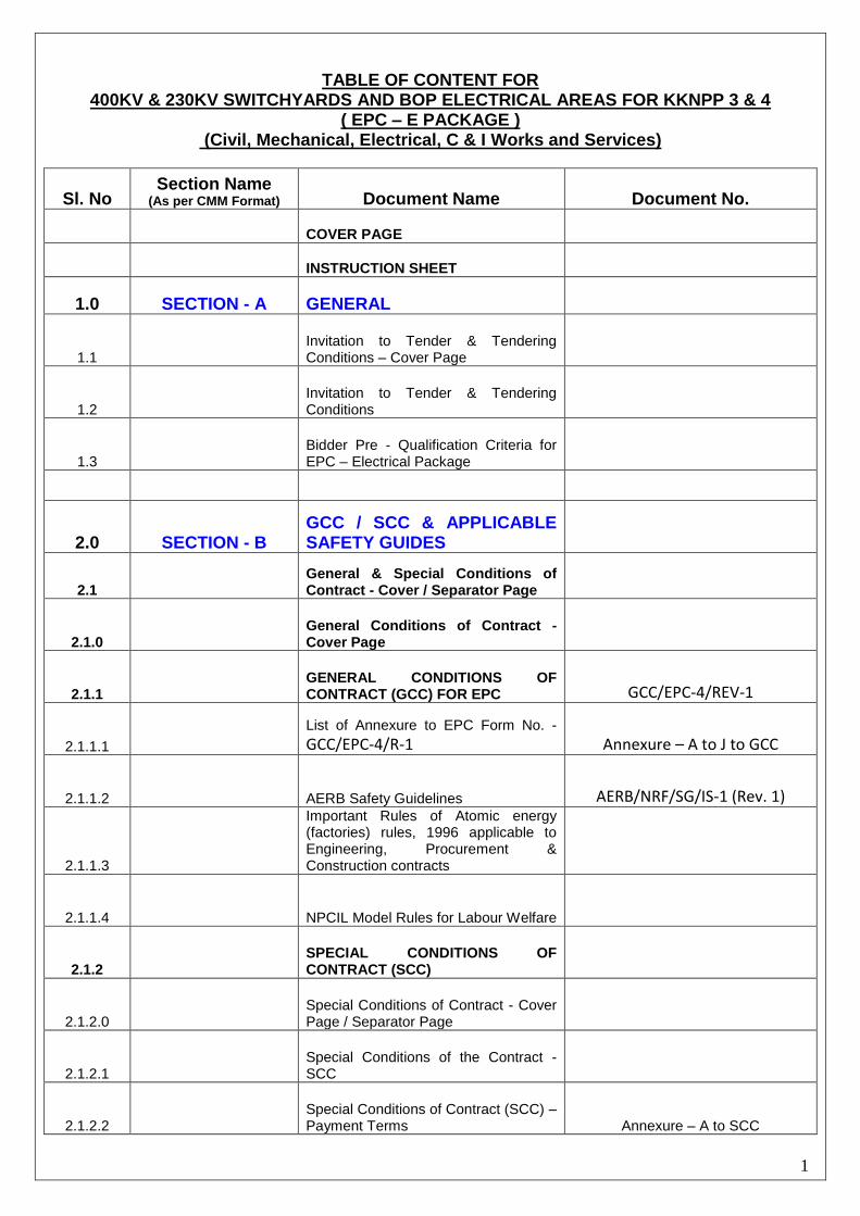
3.10.3.0 Indicative QAPs – Civil Works – Title Sheet
3.10.3.1 Indicative QAP for Civil Works
3.11
Indicative Weightages of SSCs for deriving Billing Break - Up
3.11.1
Indicative Weightages of SSCs – Supply Part
3.11.2
Indicative Weightages of SSCs – Erection & Commissioning Part
3.11.3
Indicative Weightages of SSCs – Civil Part
3.12
Indicative Milestones of the EPC Package
SECTION - D
4
FORMATS FOR SUBMISSION OF PART – 1 (TECHNICAL) OF THE TENDER (attached in case of Two Part Tender)
4 Section – D – Title Sheet
4
Tender Form for Part – I (Technical
and Commercial Bid except price) = Cover Page
4.0
Schedule Of Bidder’s Particulars W.R.T. Qualifying Criteria
4.1
Schedule of Bidder’s General Particulars
4.2 Schedule of Bidder’s experience
4.3 Schedule of Bidder’s resources
4.4
Format for submission of present commitment of the Bidder
4.5 Bidder’s Organization chart
4.6 Project & Site organization
4.7 Summary of QA/QC programme
4.8 Bidder’s safety programme
4.9
Schedule of Subcontractors & Consultants
4.10 Schedule of Sub-vendors
4.11
Exceptions & deviations on tender specification and drawings

31
Sl. No
Section Name (As per CMM Format) Document Name Document No.
4.12
Suggested changes on tender drgs/specifications
4.13
Schedule of Bidder’s queries/clarifications on Technical specifications/drawings
4.14
Format for submission of Technical Data for Mechanical items
4.15
Format for submission of Technical Data for Civil items
4.16
Format for submission of Technical Data for Control & Instrumentation items
4.17
Format for submission of Technical Data for Electrical items
4.18
Schedule of confirmation for submission of drawings/documents
4.19
Details of the Proposed Computer based Project Monitoring System.
4.20
Schedule of mandatory spares
4.21
Schedule of recommended spares
4.22
Schedule of Erection & start up spares, Maintenance tools & tackles
4.23
Time schedule
4.24
Activity schedule
4.25
Schedule for submission of drawings/documents
4.26
Schedule of Requirement of Space, Power and Water at site
4.27
Format for indicating import content of items/ components
4.28
Schedule for Bidder’s confirmation for total scope of EPC package
4.29
Format for indicating weightages & indices for price variation
4.30
Check List for Compliance of Technical Bid

32
Sl. No
Section Name (As per CMM Format) Document Name Document No.
5 SECTION - E
FORMAT FOR SUBMISSION OF
PART – II – (PRICE BID)
5.0
FORMAT FOR SUBMISSION OF
PART – II – (PRICE BID) – COVER PAGE
5.1
TENDER – FORM – PART – II
5.2 NOTES
5.3
FORMAT FOR SUBMISSION OF PRICE BID OF THE TENDER – SUMMARY SHEET
5.4
SCHEDULE OF RATES (SOR)
& ANNEXURE
5.4.1 Schedule of Rates – Supply + Special Tests + Mandatory Spares
5.4.2 Schedule of Rates – CIF Value of
Imported Items
5.4.3
Schedule of Rates – Civil Works
5.4.4
Schedule of Rates – Erection & Commissioning
5.4.5
Schedule of Rates – Ex Patriate Field Labour Charges
5.4.6
Schedule of Rates – Transformer Loading Charges
5.4.7
Schedule of Rates – Format for Recommended Spares
5.4.8
Schedule of Rates – Summary Sheet