Embed Size (px)
Citation preview
PRODUCT LITERATUREBELLEVUE, OH 44811
INSTALLATION INSTRUCTIONS UHPA
UNIT HEATERS Table Of Contents
Unit Dimensions………………….………………….. 1 Leak Check…………………………….. 8Shipping……………………………………………... 2 Start-Up Operation……………………… 9Requirements………………………………………… 2 Heating Sequence of Operation….……... 11Unit Heater Installation……………………………… 3 Ignition Control LED…………….……... 11Combustion & Ventilation Air……………………… 3 Optional Gas Conversion Kits………….. 11Rotation Of Induced Draft Blower…………………. 3 Adjustments…………………………….. 12Venting………………………………………………. 4 Service………………………………….. 14Electrical Connections……………………………….. 8 Typical Wiring Diagram………………... 15Gas Connections……………………………………... 8 Warranty………………………………... 16 Template………………………………... 18
RETAIN THESE INSTRUCTIONS FOR FUTURE REFERENCE
Do not store or use gasoline orother flammable vapors andliquids in the vicinity of this or anyother appliance.
Installation and service must beperformed by a qualified installer,service agency or the gas supplier.
WHAT TO DO IF YOU SMELL GAS:• Do not try to light any appliance.• Extinguish any open flame.• Do not touch any electrical switch; do not use any
phone in your building.• Immediately call your gas supplier from a neighbor's
phone. Follow the gas supplier's instructions.• If you cannot reach your gas supplier; call the fire
department.
If the information in this manual is notfollowed exactly, a fire or explosionmay result causing property damage,personal injury or loss of life.
WARNING
P/N: 065274401 ORGINATED: 10/99 REVISED: 3/01 SUPERSEDES: 065274400
1/2 (13)
H
TOP VIEW
SIDE VIEW
ADJUSTABLELOUVERS
GASVALVEHEAT
EXCHANGER
DIRECTDRIVE FAN
FLUEOUTLET
ELECTRICAL INLETS
AIR
FLOW
INDUCED DRAFTBLOWER
END VIEW
A
B
C
EF
G
D*7-5/8(194) 1/2
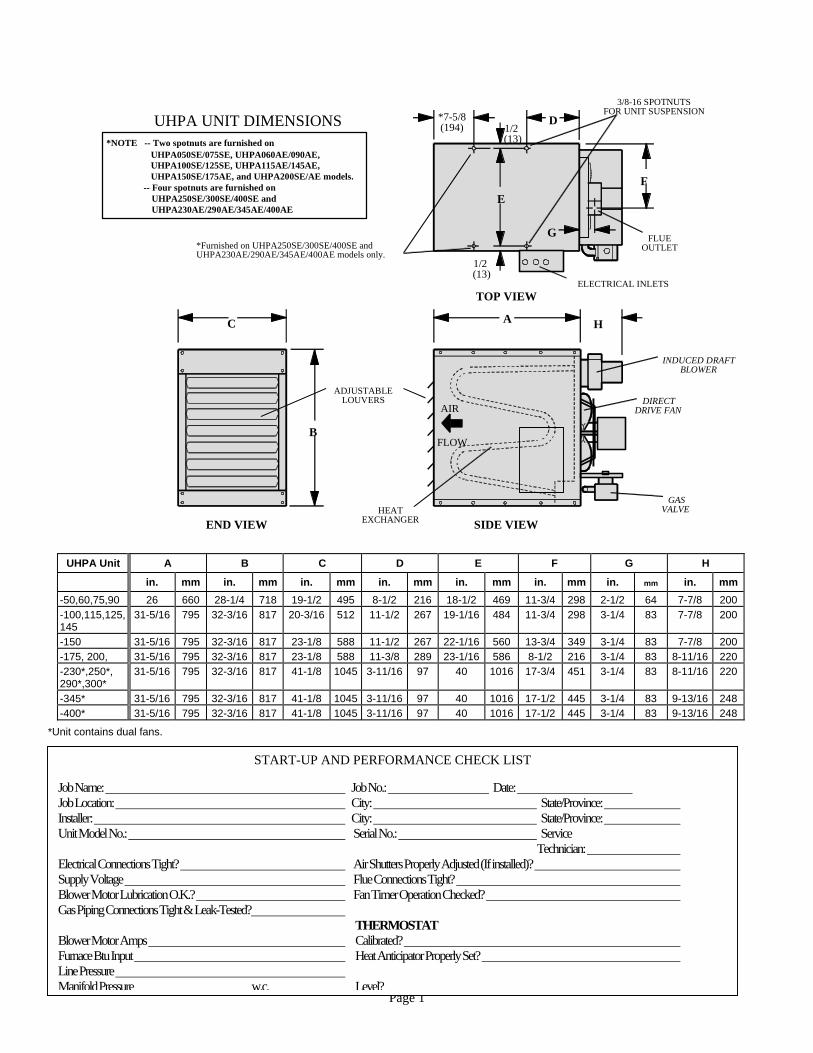
(13) UHPA UNIT DIMENSIONS
*Furnished on UHPA250SE/300SE/400SE andUHPA230AE/290AE/345AE/400AE models only.
3/8-16 SPOTNUTSFOR UNIT SUSPENSION
*NOTE -- Two spotnuts are furnished on UHPA050SE/075SE, UHPA060AE/090AE, UHPA100SE/125SE, UHPA115AE/145AE, UHPA150SE/175AE, and UHPA200SE/AE models. -- Four spotnuts are furnished on UHPA250SE/300SE/400SE and UHPA230AE/290AE/345AE/400AE
UHPA Unit A B C D E F G H in. mm in. mm in. mm in. mm in. mm in. mm in. mm in. mm-50,60,75,90 26 660 28-1/4 718 19-1/2 495 8-1/2 216 18-1/2 469 11-3/4 298 2-1/2 64 7-7/8 200 -100,115,125,145
31-5/16 795 32-3/16 817 20-3/16 512 11-1/2 267 19-1/16 484 11-3/4 298 3-1/4 83 7-7/8 200
-150 31-5/16 795 32-3/16 817 23-1/8 588 11-1/2 267 22-1/16 560 13-3/4 349 3-1/4 83 7-7/8 200 -175, 200, 31-5/16 795 32-3/16 817 23-1/8 588 11-3/8 289 23-1/16 586 8-1/2 216 3-1/4 83 8-11/16 220 -230*,250*, 290*,300*
31-5/16 795 32-3/16 817 41-1/8 1045 3-11/16 97 40 1016 17-3/4 451 3-1/4 83 8-11/16 220
-345* 31-5/16 795 32-3/16 817 41-1/8 1045 3-11/16 97 40 1016 17-1/2 445 3-1/4 83 9-13/16 248 -400* 31-5/16 795 32-3/16 817 41-1/8 1045 3-11/16 97 40 1016 17-1/2 445 3-1/4 83 9-13/16 248
*Unit contains dual fans.
Job Name: Job Location: Installer: Unit Model No.:
Electrical Connections Tight? Supply Voltage Blower Motor Lubrication O.K.? Gas Piping Connections Tight & Leak-Tested Blower Motor Amps Furnace Btu Input Line Pressure ManifoldPressure
START-UP AND PERFORMANCE CHECK LIST
Job No.: Date: City: State/Province: City: State/Province: Serial No.: Service
Technician: Air Shutters Properly Adjusted (If installed)? Flue Connections Tight? Fan Timer Operation Checked? ? THERMOSTAT Calibrated? Heat Anticipator Properly Set? w.c. Level?
Page 1
Shipping The heater is completely assembled with the following parts packed inside: installation and operating instructions, warranty certificate, and flue transition piece. Check the unit for shipping damage. The receiving party should contact the last carrier
mediately if any shipping damage is found. im Requirements – CSA in the USA
Installation of UHPA gas unit heaters must conform with local building codes or, in the absence of local codes, with the current National Fuel Gas Code ANSI-Z223.1. Installation in aircraft hangers must be in accordance with the current Standard for Aircraft Hangers ANSI/NFPA No. 409. Installation in parking structures must be in accordance with the current Standard for Parking Structures ANSI/NFPA No. 88A. Installation in repair garages must be in accordance with the current Standard for Repair Garages ANSI/NFPA No. 88B. Authorities having jurisdiction should be consulted before installation. Air for combustion and ventilation must conform to the methods outlined in ANSI Z223.1, section 5.3, Air for Combustion and Ventilation, or applicable provisions of local building codes. The National Fuel Gas Code is available from: American National Standard Institute, Inc. 1430 Broadway New York, NY 10018 These units are C.S.A. International design certified. These unit heaters are certified for installation to combustible material as listed in table 1 and on unit rating plate. Accessibility and service clearances must be observed in addition to fire protection clearances. All electrical wiring and ground for unit must be in accordance with the regulations of the current National Electric Code ANSI/NFPA No. 70. The National Electric Code is available from: The National Fire Protection Association 470 Atlantic Avenue
oston, MA 02210 B Requirements – CSA in Canada
The instructions are intended only as a general guide and do not supersede local codes in any way. Authorities having jurisdiction should be consulted before installation. The installation must conform with local building codes or in the absence of local codes, with the current codes CAN/CGA-B149.1 “Installation Code for Natural Gas Burning Appliances and
Equipment" and CAN/CGA-B149.2 “Installation Code for Propane Burning Appliances and Equipment." All electrical wiring and grounding for the unit must also comply with the Canadian Electrical Code CSA C22.1, current edition.
These unit heaters are CSA International certified for the clearances to combustible material listed on the rating plate and table 1. Adequate clearance shall be provided around the appliance and around air openings into the combustion chamber. Provision shall be made for service accessibility to the heater. Note that fire protection clearances may be exceeded to provide additional space for service and accessibility.
PUBLIC GARAGE:
1- In a storage area, clearance from heaters to combustible materials must be such that the material shall not attain a temperature above 160°F by continuous operation of the unit.
2- Eight foot minimum clearance from the floor to the
bottom of the heater must be maintained. Refer to the CAN/CGA-B149 Codes.
AIRCRAFT HANGER:
1- In an area where aircraft are housed or serviced, 10'
minimum clearance from highest surface of aircraft to bottom of the heater must be maintained.
2- In other areas, 8' minimum clearance from the floor to bottom of heater must be maintained.
3- Heaters should be located so as to be protected from damage from aircraft or other appliances needed for servicing of aircraft. Refer to requirements of the enforcing authorities.
In a confined area, the heater must be installed in accordance with the CAN/CGA-B149 Codes. Be sure to check with local codes and ordinances for additional requirements.
TABLE 1 UNIT CLEARANCES
Top Sides Bottom Rear Single wall vent*in mm in mm in mm in mm in mm
6 152 6 152 0 0 18 457 6 152 * Except for listed clearance thimbles.
Page 2
Unit Heater Installation
Locate the unit in the desired location as governed by clearances, vent connection, air direction, gas supply, electrical supply and service accessibility. Remove and retain screws securing shipping brackets to base of unit. Discard shipping brackets and reinstall screws in unit. On UHPA050, 060, 075, 090, 100, 115, 125, 145, 150, 175,and 200 units, 3/8" X 16 threads/on spot nuts are furnished at the balance point (2 positions only). On UHPA230, 250, 290, 300, 345, and 400 units, spot nuts are furnished at each corner of the unit for 3/8" X 16 threaded rods.
1- Cut threaded rods to desired length and thread a 3/8" nut onto the rod.
2- Slide a flat washer onto the threaded rod AFTER the nut (7/16"I.D. X 1" O.D. X 1/16THK washer).
3- Screw the rods (two or four) into the spot nuts on the unit.
4- Tighten nuts to secure unit to rods.
IMPORTANT Do not use the gas manifold pipe to lift unit. Any excessive upward or downward force on the manifold pipe and bracket assembly can cause the ignition burner and igniter to become misaligned. Combustion and Ventilation Air
Adequate facilities for supplying air for combustion and ventilation must be provided in accordance with the latest edition of section 5.3, Air for Combustion and Ventilation, of the National Fuel Gas Code, ANSI Z223.1, in the U.S.A., CAN/CGA-B149 Installation Codes in Canada, or applicable provisions of local building codes. All gas-fired appliances require air to be used for the combustion process. In many buildings today, there is a negative indoor air pressure caused by exhaust fans, etc. If sufficient quantities of combustion air are not available, the heater or another appliance will operate in an inefficient manner, resulting in incomplete combustion which can result in the production of excessive carbon monoxide. CAUTION - Insufficient combustion air can cause headaches, nausea, dizziness, asphyxiation or death.
If indoor air is to be used for combustion, it must be free of the following substances or the life of the heat exchanger will be adversely affected: chlorine, carbon tetrachloride, cleaning solvent, halogen refrigerants, acids, cements and glues, printing inks, fluorides, paint removers, varnishes, or any other corrosives.
Rotation of Induced Draft Blower
To facilitate convenient installation of the unit heater, the induced draft blower on some units may be rotated to better suit individual applications. The UHPA050 through UHPA150 induced draft blower may be rotated 90° either to the left or right of the original vertical position. NOTE - It is not permissible to rotate the induced draft assemblies of the UHPA175 through UHPA400 unit heaters. Rotate the induced draft assembly as follows: 1- Remove the unit heater from the carton. 2- Decide unit heater orientation. It may be advantageous
to rotate the induced draft blower to other than the original up position. The vent can be mounted in one of three discharge positions: up, left, or right. If the blower is to be rotated, follow the instructions in this section; otherwise, refer to instructions under “Venting" section.
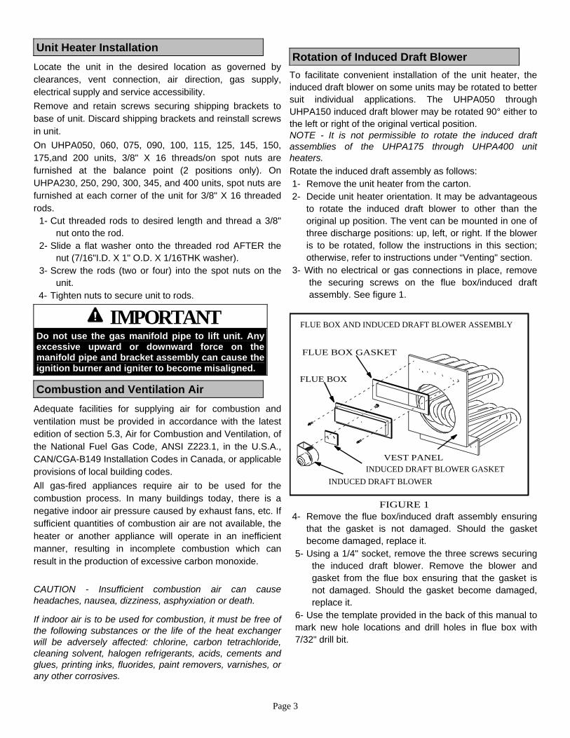
3- With no electrical or gas connections in place, remove the securing screws on the flue box/induced draft assembly. See figure 1.
FIGURE 1
FLUE BOX AND INDUCED DRAFT BLOWER ASSEMBLY
VEST PANEL
FLUE BOX GASKET
FLUE BOX
INDUCED DRAFT BLOWER GASKETINDUCED DRAFT BLOWER
4- Remove the flue box/induced draft assembly ensuring
that the gasket is not damaged. Should the gasket become damaged, replace it.
5- Using a 1/4" socket, remove the three screws securing the induced draft blower. Remove the blower and gasket from the flue box ensuring that the gasket is not damaged. Should the gasket become damaged, replace it.
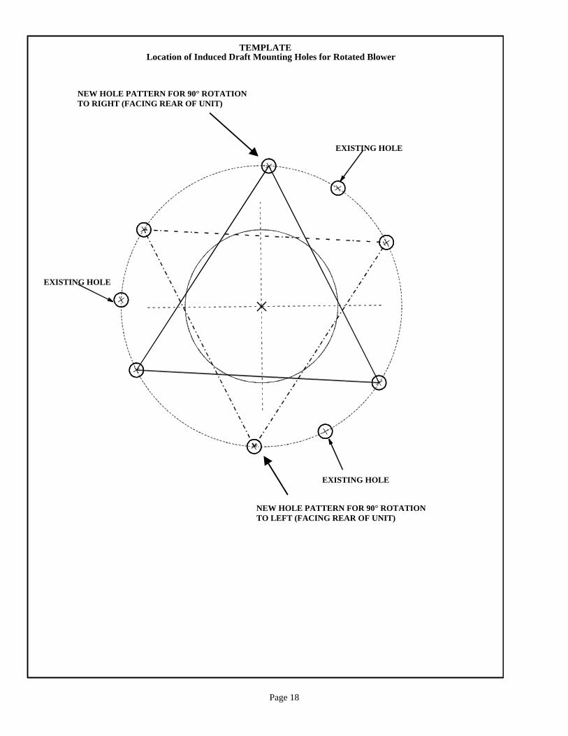
6- Use the template provided in the back of this manual to mark new hole locations and drill holes in flue box with 7/32" drill bit.
Page 3
Page 4
7- Rotate both the blower and the gasket 90° to the desired position. Reinsert and tighten the three blower securing screws (#8-16 X 1/2" HWHSMS). Place the gasket between the induced draft blower and the flue box.
8- Position the flue box/induced draft assembly on the vest panel. Place the gasket between the flue box and the vest panel. Fasten the flue box using the flue box securing screws (#10-16 X 5/8" HWHSMS) and a 5/16" drive.
9- An alternate sheet metal flue transition is certified for use with rotated induced draft blowers. The 2” to 3” transition #33J94 is for use with 3” diameter flue. The 3” to 4” transition #33J93 is for use with 4” diameter flue.
10- The unit heater is now ready for installation as described in the section under Venting.
Venting A-General Recommendations and Requirements NOTE - The vent is a passageway, vertical or nearly so, used to convey flue gases from an appliance, or its vent connector, to the outside atmosphere. The vent connector is the pipe or duct that connects a fuel-gas burning appliance to a vent or chimney.
NOTE - Local codes may supersede any of these provisions.
UHPA unit heaters must be vented in compliance with all local codes or requirements of the local utility, the current standards of the (American) National Fuel Gas Code, ANSI Z223.1 or (Canada) CAN/CGA-B149 Installation Codes, and the following instructions.
A sheet metal flue transition is supplied with this certified unit. It must not be modified or altered and must be installed on the outlet of the induced draft blower assembly prior to the installation of the vent connector. Failure to comply with this requirement will void the certification of the unit by the approval agencies.
The vent connector shall be 3” (76mm) on UHPA050 and 060 models. On UHPA075 through UHPA150 models the vent connector shall be 4" (102mm) diameter. On UHPA175 through UHPA300 models the vent connector shall be 5" (127mm) diameter. On UHPA345 and 400 models, the vent connector shall be 6" (152mm) diameter. In all cases, a flue transition piece (supplied) is required to fit over the outlet of the induced draft assembly on the appliance. On UHPA400 models, a minimum 6" (162mm) straight section must be placed between the flue transition and the first elbow of the vent.
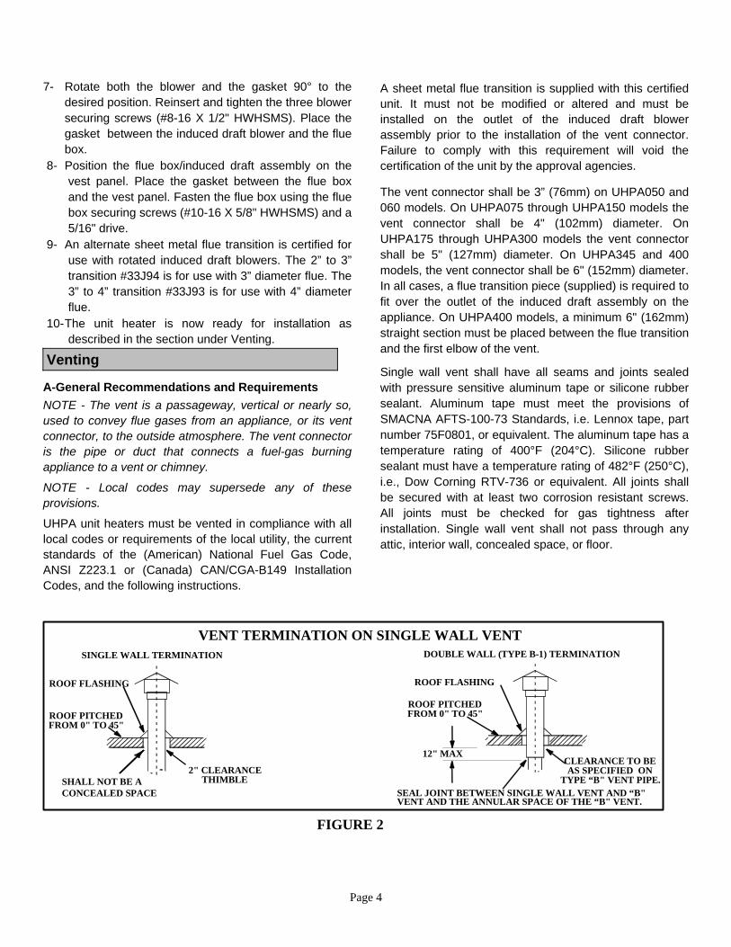
Single wall vent shall have all seams and joints sealed with pressure sensitive aluminum tape or silicone rubber sealant. Aluminum tape must meet the provisions of SMACNA AFTS-100-73 Standards, i.e. Lennox tape, part number 75F0801, or equivalent. The aluminum tape has a temperature rating of 400°F (204°C). Silicone rubber sealant must have a temperature rating of 482°F (250°C), i.e., Dow Corning RTV-736 or equivalent. All joints shall be secured with at least two corrosion resistant screws. All joints must be checked for gas tightness after installation. Single wall vent shall not pass through any attic, interior wall, concealed space, or floor.
FIGURE 2
VENT TERMINATION ON SINGLE WALL VENTSINGLE WALL TERMINATION DOUBLE WALL (TYPE B-1) TERMINATION
ROOF FLASHING
ROOF PITCHEDFROM 0" TO 45"
2" CLEARANCETHIMBLE
SEAL JOINT BETWEEN SINGLE WALL VENT AND “B"VENT AND THE ANNULAR SPACE OF THE “B" VENT.
CLEARANCE TO BEAS SPECIFIED ON
TYPE “B" VENT PIPE.
12" MAX
ROOF FLASHING
ROOF PITCHEDFROM 0" TO 45"
SHALL NOT BE ACONCEALED SPACE
Page 5
Venting - Continued
B-Vertical Vents Using Metal Vent Pipe UHPA unit heaters are listed as Category I appliances for vertical vent installations. 1- SEP unit heaters are to be used with NFPA- or ANSI-
approved chimneys, U.L. listed type B-1 gas vents, single wall metal pipe, or listed chimney lining system for gas venting where applicable, as well as the modifications and limitations listed in figure 2.
2-- Keep the vent connector runs as short as possible with a minimum number of elbows. Refer to the (American) National Fuel Gas Code ANSI Z223.1 or (Canada) CAN/CGA-B149 Installation Code for maximum vent and vent connector lengths. Horizontal run of the vent connector from the induced draft blower outlet to the chimney/vent pipe cannot exceed the values table 2. A single 3" (76mm), 4" (102mm), or 5" (127mm) elbow is equivalent to 5 ft. (1.5m) of vent pipe. A single 6" (152mm) elbow is equivalent to 9 feet (2.7m) of vent pipe.
3- When the length of a single wall vent, including elbows, exceeds the length shown in table 3, the vent shall be insulated along its entire length with a minimum of 1/2" thick foil faced fiberglass 1-1/2# density insulation. If a single wall vent connector is used in an unheated area it shall be insulated. Failure to do so will result in condensation of flue gases.
6- The UHPA may be vented vertically as a single appliance or as a common vent with other gas-fired appliances. In a common venting situation, vent connectors for other appliances must be joined to the vent at least 4" (102mm) above the highest connected UHPA connection. When common venting with other appliances, maintain at least a 4" (102mm) vertical separation between the vent connectors. Refer to common venting tables for proper vent size.
5 Clearance to combustible material is 6" (152mm) for single wall vent pipe except where a listed clearance thimble is used. Clearance to combustible material for type B-1 vent or factory-built chimney is per manufacturer’s instructions.
6 The vent shall be supported with hangers no more than 3' (1m) apart to prevent movement after installation. All horizontal vent connector runs shall have a slope up to the vertical vent of at least 1/4" per foot (1mm per 50mm).
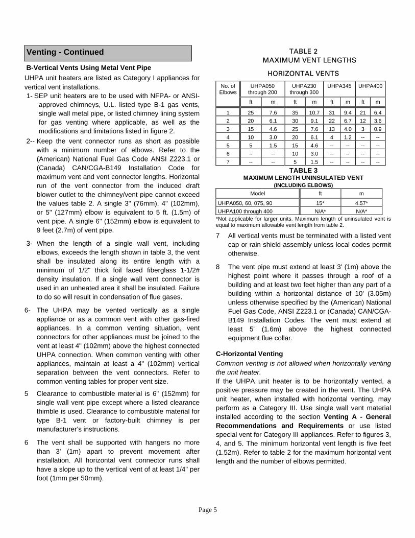
TABLE 2 MAXIMUM VENT LENGTHS
HORIZONTAL VENTS
No. of Elbows
UHPA050 through 200
UHPA230 through 300
UHPA345 UHPA400
ft m ft m ft m ft m
1 25 7.6 35 10.7 31 9.4 21 6.4 2 20 6.1 30 9.1 22 6.7 12 3.6 3 15 4.6 25 7.6 13 4.0 3 0.9 4 10 3.0 20 6.1 4 1.2 -- -- 5 5 1.5 15 4.6 -- -- -- -- 6 -- -- 10 3.0 -- -- -- -- 7 -- -- 5 1.5 -- -- -- --
TABLE 3 MAXIMUM LENGTH UNINSULATED VENT
(INCLUDING ELBOWS) Model ft m
UHPA050, 60, 075, 90 15* 4.57* UHPA100 through 400 N/A* N/A*
*Not applicable for larger units. Maximum length of uninsulated vent is equal to maximum allowable vent length from table 2.
7 All vertical vents must be terminated with a listed vent cap or rain shield assembly unless local codes permit otherwise.
8 The vent pipe must extend at least 3' (1m) above the highest point where it passes through a roof of a building and at least two feet higher than any part of a building within a horizontal distance of 10' (3.05m) unless otherwise specified by the (American) National Fuel Gas Code, ANSI Z223.1 or (Canada) CAN/CGA-B149 Installation Codes. The vent must extend at least 5' (1.6m) above the highest connected equipment flue collar.
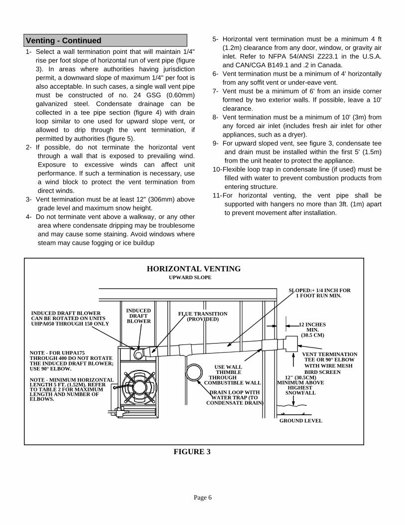
C-Horizontal Venting Common venting is not allowed when horizontally venting the unit heater. If the UHPA unit heater is to be horizontally vented, a positive pressure may be created in the vent. The UHPA unit heater, when installed with horizontal venting, may perform as a Category III. Use single wall vent material installed according to the section Venting A - General Recommendations and Requirements or use listed special vent for Category III appliances. Refer to figures 3, 4, and 5. The minimum horizontal vent length is five feet (1.52m). Refer to table 2 for the maximum horizontal vent length and the number of elbows permitted.
Page 6
Venting - Continued 1- Select a wall termination point that will maintain 1/4"
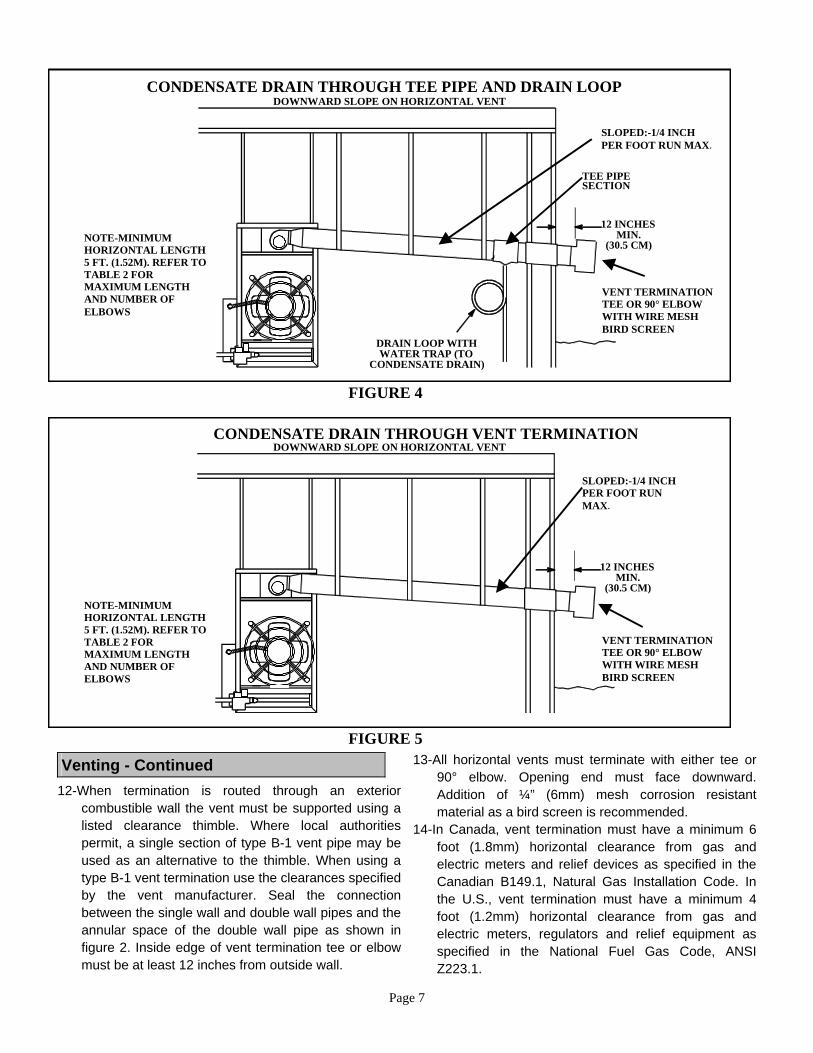
rise per foot slope of horizontal run of vent pipe (figure 3). In areas where authorities having jurisdiction permit, a downward slope of maximum 1/4" per foot is also acceptable. In such cases, a single wall vent pipe must be constructed of no. 24 GSG (0.60mm) galvanized steel. Condensate drainage can be collected in a tee pipe section (figure 4) with drain loop similar to one used for upward slope vent, or allowed to drip through the vent termination, if permitted by authorities (figure 5).
2- If possible, do not terminate the horizontal vent through a wall that is exposed to prevailing wind. Exposure to excessive winds can affect unit performance. If such a termination is necessary, use a wind block to protect the vent termination from direct winds.
3- Vent termination must be at least 12" (306mm) above grade level and maximum snow height.
4- Do not terminate vent above a walkway, or any other area where condensate dripping may be troublesome and may cause some staining. Avoid windows where steam may cause fogging or ice buildup
5- Horizontal vent termination must be a minimum 4 ft (1.2m) clearance from any door, window, or gravity air inlet. Refer to NFPA 54/ANSI Z223.1 in the U.S.A. and CAN/CGA B149.1 and .2 in Canada.
6- Vent termination must be a minimum of 4' horizontally from any soffit vent or under-eave vent.
7- Vent must be a minimum of 6' from an inside corner formed by two exterior walls. If possible, leave a 10' clearance.
8- Vent termination must be a minimum of 10' (3m) from any forced air inlet (includes fresh air inlet for other appliances, such as a dryer).
9- For upward sloped vent, see figure 3, condensate tee and drain must be installed within the first 5' (1.5m) from the unit heater to protect the appliance.
10- Flexible loop trap in condensate line (if used) must be filled with water to prevent combustion products from entering structure.
11- For horizontal venting, the vent pipe shall be supported with hangers no more than 3ft. (1m) apart to prevent movement after installation.
FIGURE 3
VENT TERMINATIONTEE OR 90° ELBOWWITH WIRE MESHBIRD SCREEN
HORIZONTAL VENTING
FLUE TRANSITION(PROVIDED)
INDUCED DRAFT BLOWERCAN BE ROTATED ON UNITSUHPA050 THROUGH 150 ONLY
NOTE - FOR UHPA175THROUGH 400 DO NOT ROTATETHE INDUCED DRAFT BLOWER;USE 90° ELBOW.
INDUCEDDRAFT
BLOWER
12" (30.5CM)MINIMUM ABOVE
HIGHESTSNOWFALLDRAIN LOOP WITH
WATER TRAP (TOCONDENSATE DRAIN)
USE WALLTHIMBLE
THROUGHCOMBUSTIBLE WALL
SLOPED:+ 1/4 INCH FOR1 FOOT RUN MIN.
(30.5 CM)
12 INCHESMIN.
GROUND LEVEL
UPWARD SLOPE
NOTE - MINIMUM HORIZONTALLENGTH 5 FT. (1.52M). REFERTO TABLE 2 FOR MAXIMUMLENGTH AND NUMBER OFELBOWS.
Page 7
FIGURE 4
SLOPED:-1/4 INCHPER FOOT RUN MAX.
VENT TERMINATIONTEE OR 90° ELBOWWITH WIRE MESHBIRD SCREEN
CONDENSATE DRAIN THROUGH TEE PIPE AND DRAIN LOOP
TEE PIPESECTION
DOWNWARD SLOPE ON HORIZONTAL VENT
DRAIN LOOP WITHWATER TRAP (TO
CONDENSATE DRAIN)
NOTE-MINIMUMHORIZONTAL LENGTH5 FT. (1.52M). REFER TOTABLE 2 FORMAXIMUM LENGTHAND NUMBER OFELBOWS
(30.5 CM)
12 INCHESMIN.
FIGURE 5
CONDENSATE DRAIN THROUGH VENT TERMINATION
VENT TERMINATIONTEE OR 90° ELBOWWITH WIRE MESHBIRD SCREEN
DOWNWARD SLOPE ON HORIZONTAL VENT
NOTE-MINIMUMHORIZONTAL LENGTH5 FT. (1.52M). REFER TOTABLE 2 FORMAXIMUM LENGTHAND NUMBER OFELBOWS
SLOPED:-1/4 INCHPER FOOT RUNMAX.
(30.5 CM)
12 INCHESMIN.
Venting - Continued
12-When termination is routed through an exterior combustible wall the vent must be supported using a listed clearance thimble. Where local authorities permit, a single section of type B-1 vent pipe may be used as an alternative to the thimble. When using a type B-1 vent termination use the clearances specified by the vent manufacturer. Seal the connection between the single wall and double wall pipes and the annular space of the double wall pipe as shown in figure 2. Inside edge of vent termination tee or elbow must be at least 12 inches from outside wall.
13-All horizontal vents must terminate with either tee or 90° elbow. Opening end must face downward. Addition of ¼” (6mm) mesh corrosion resistant material as a bird screen is recommended.
14-In Canada, vent termination must have a minimum 6 foot (1.8mm) horizontal clearance from gas and electric meters and relief devices as specified in the Canadian B149.1, Natural Gas Installation Code. In the U.S., vent termination must have a minimum 4 foot (1.2mm) horizontal clearance from gas and electric meters, regulators and relief equipment as specified in the National Fuel Gas Code, ANSI Z223.1.
Page 8
Electrical Connections NOTE - The UHPA series unit heaters use a direct spark ignition system. There is no pilot necessary as the spark lights the main burner as the gas valve is turned on. The direct spark ignition control board emits radio noise as the sparking process is underway. The level of energy may be sufficient to disturb a logic circuit in a microprocessor controlled thermostat. It is recommended that an isolation relay be used when connecting the UHPA series unit heaters to a microprocessor controlled thermostat. Install the thermostat according to instructions provided. Install a separate fused disconnect switch, fused according to blower motor size. Connect wiring through knockout on the junction box located on the side of the unit heater. Refer to heater wiring diagram for connection information. Use 18 gauge wire or larger for thermostat connections. Electrically ground unit in accordance with local codes or, in the absence of local codes, in accordance with the current National Electrical Code (ANSI/NFPA No. 70)in the U.S.A., and in Canada with the current Canadian Electrical code, Part 1 (CSA C22.1) NOTE - Uninsulated ground wires must be wrapped in electrical tape to avoid damage to the electrical system.Connect field wiring as shown on wiring diagram on unit. Also refer to typical diagram in this manual. An additional thermostat wire must be run to terminal "G" on
eater when continuous blower is desired. h Gas Connection
When connecting gas supply, the length of the run from the meter must be considered in determining the pipe size to avoid excessive pressure drop. A line pressure of 7" w.c. (178mm w.c.) for natural gas should be maintained when sizing piping. A line pressure of 13” w.c. (330mm w.c.) should be maintained for liquefied petroleum (LP) gas. For correct sizing of piping, consult the utility having jurisdiction.
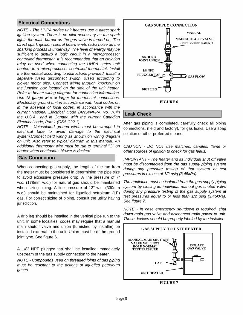
A drip leg should be installed in the vertical pipe run to the unit. In some localities, codes may require that a manual main shutoff valve and union (furnished by installer) be installed external to the unit. Union must be of the ground joint type. See figure 6. A 1/8" NPT plugged tap shall be installed immediately upstream of the gas supply connection to the heater. NOTE - Compounds used on threaded joints of gas piping must be resistant to the actions of liquefied petroleum gases.
FIGURE 6
GROUNDJOINT UNION
DRIP LEG
MANUAL
MAIN SHUT-OFF VALVE(Furnished by Installer)
GAS FLOW
1/8 NPTPLUGGED TAP
GAS SUPPLY CONNECTION
Leak Check
After gas piping is completed, carefully check all piping connections, (field and factory), for gas leaks. Use a soap solution or other preferred means.
CAUTION - DO NOT use matches, candles, flame or other sources of ignition to check for gas leaks.
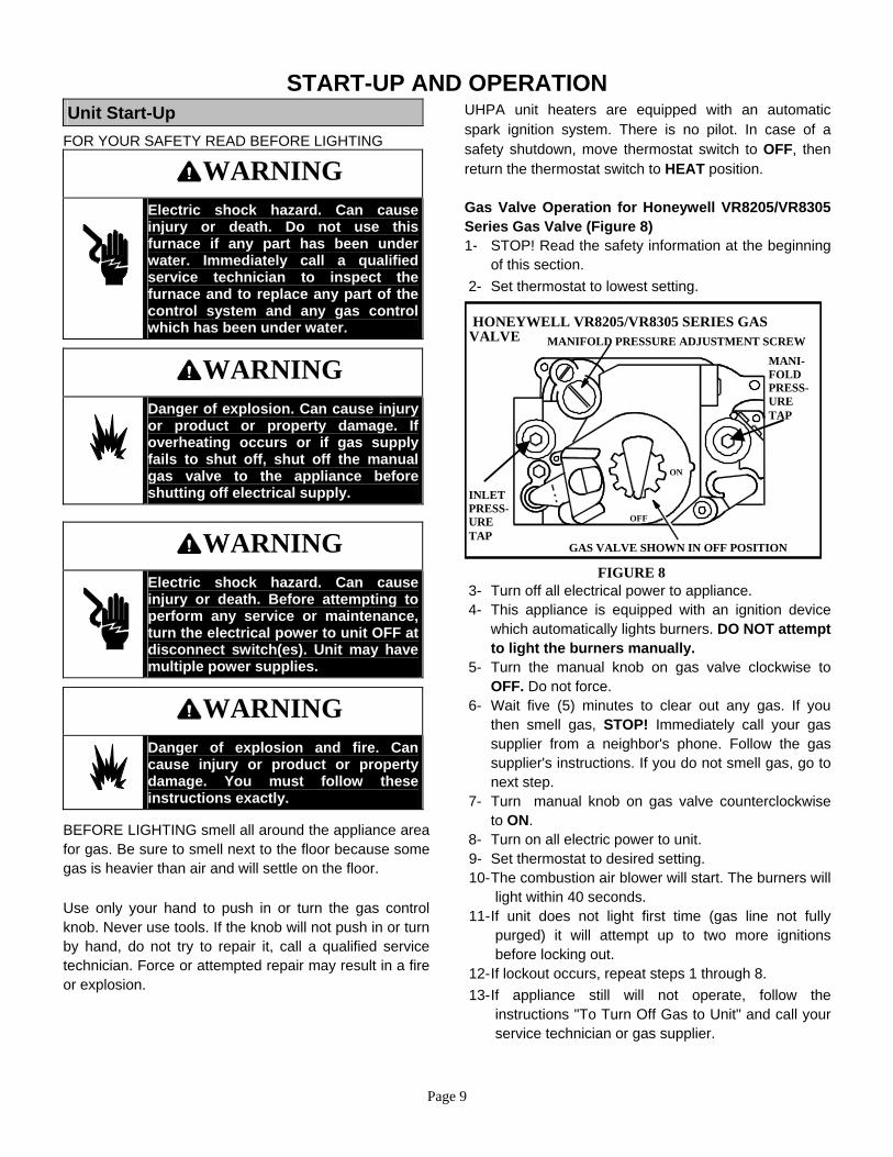
IMPORTANT - The heater and its individual shut off valve must be disconnected from the gas supply piping system during any pressure testing of that system at test pressures in excess of 1/2 psig (3.45kPa).
The appliance must be isolated from the gas supply piping system by closing its individual manual gas shutoff valve during any pressure testing of the gas supply system at test pressures equal to or less than 1/2 psig (3.45kPa). See figure 7.
NOTE - In case emergency shutdown is required, shut down main gas valve and disconnect main power to unit. These devices should be properly labeled by the installer.
FIGURE 7
MANUAL MAIN SHUT-OFFVALVE WILL NOT
HOLD NORMALTEST PRESSURE
CAP
ISOLATEGAS VALVE
GAS SUPPLY TO UNIT HEATER
UNIT HEATER
Page 9
START-UP AND OPERATION Unit Start-Up
FOR YOUR SAFETY READ BEFORE LIGHTING
WARNING
Electric shock hazard. Can cause injury or death. Do not use this furnace if any part has been under water. Immediately call a qualified service technician to inspect the furnace and to replace any part of the control system and any gas control which has been under water.
WARNING
Danger of explosion. Can cause injury or product or property damage. If overheating occurs or if gas supply fails to shut off, shut off the manual gas valve to the appliance before shutting off electrical supply.
WARNING
Electric shock hazard. Can cause injury or death. Before attempting to perform any service or maintenance, turn the electrical power to unit OFF at disconnect switch(es). Unit may have multiple power supplies.
WARNING
Danger of explosion and fire. Can cause injury or product or property damage. You must follow these instructions exactly.
BEFORE LIGHTING smell all around the appliance area for gas. Be sure to smell next to the floor because some gas is heavier than air and will settle on the floor. Use only your hand to push in or turn the gas control knob. Never use tools. If the knob will not push in or turn by hand, do not try to repair it, call a qualified service technician. Force or attempted repair may result in a fire or explosion.
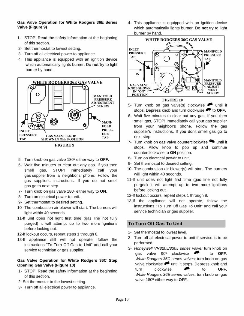
UHPA unit heaters are equipped with an automatic spark ignition system. There is no pilot. In case of a safety shutdown, move thermostat switch to OFF, then return the thermostat switch to HEAT position. Gas Valve Operation for Honeywell VR8205/VR8305 Series Gas Valve (Figure 8) 1- STOP! Read the safety information at the beginning
of this section. 2- Set thermostat to lowest setting.
MANIFOLD PRESSURE ADJUSTMENT SCREW
ON
OFF
FIGURE 8
HONEYWELL VR8205/VR8305 SERIES GASVALVE
INLETPRESS-URETAP
MANI-FOLDPRESS-URETAP
GAS VALVE SHOWN IN OFF POSITION
3- Turn off all electrical power to appliance. 4- This appliance is equipped with an ignition device
which automatically lights burners. DO NOT attempt to light the burners manually.
5- Turn the manual knob on gas valve clockwise to OFF. Do not force.
6- Wait five (5) minutes to clear out any gas. If you then smell gas, STOP! Immediately call your gas supplier from a neighbor's phone. Follow the gas supplier's instructions. If you do not smell gas, go to next step.
7- Turn manual knob on gas valve counterclockwise to ON.
8- Turn on all electric power to unit. 9- Set thermostat to desired setting. 10- The combustion air blower will start. The burners will
light within 40 seconds. 11- If unit does not light first time (gas line not fully
purged) it will attempt up to two more ignitions before locking out.
12- If lockout occurs, repeat steps 1 through 8. 13- If appliance still will not operate, follow the
instructions "To Turn Off Gas to Unit" and call your service technician or gas supplier.
Page 10
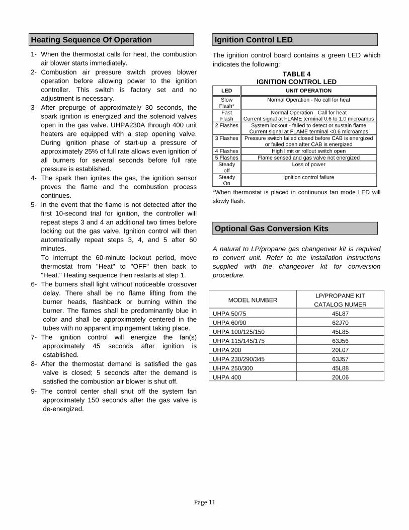
Gas Valve Operation for White Rodgers 36E Series Valve (Figure 9) 1- STOP! Read the safety information at the beginning
of this section. 2- Set thermostat to lowest setting. 3- Turn off all electrical power to appliance. 4 This appliance is equipped with an ignition device
which automatically lights burner. Do not try to light burner by hand.
FIGURE 9
WHITE RODGERS 36E GAS VALVE
GAS VALVE KNOBSHOWN IN OFF POSITION
NO
OFF
MANIFOLDPRESSURE
ADJUSTMENTSCREW
MANI-FOLDPRESS-URETAP
INLETPRESSURETAP
5- Turn knob on gas valve 180º either way to OFF. 6- Wait five minutes to clear out any gas. If you then
smell gas, STOP! Immediately call your gas supplier from a neighbor's phone. Follow the gas supplier's instructions. If you do not smell gas go to next step.
7- Turn knob on gas valve 180º either way to ON. 8- Turn on electrical power to unit. 9- Set thermostat to desired setting. 10- The combustion air blower will start. The burners will
light within 40 seconds. 11-If unit does not light first time (gas line not fully
purged) it will attempt up to two more ignitions before locking out.
12-If lockout occurs, repeat steps 1 through 8. 13-If appliance still will not operate, follow the
instructions "To Turn Off Gas to Unit" and call your service technician or gas supplier.
Gas Valve Operation for White Rodgers 36C Step Opening Gas Valve (Figure 10) 1- STOP! Read the safety information at the beginning
of this section. 2 Set thermostat to the lowest setting. 3- Turn off all electrical power to appliance.
4- This appliance is equipped with an ignition device which automatically lights burner. Do not try to light burner by hand.
WHITE RODGERS 36C GAS VALVE
GAS VALVEKNOB SHOWN
IN "ON"POSITION
FIGURE 10
IN
MANIFOLDPRESSURE
ADJUST-MENTSCREW
MANIFOLDPRESSURETAP
INLETPRESSURETAP
5- Turn knob on gas valve(s) clockwise until it
stops. Depress knob and turn clockwise to OFF. 6- Wait five minutes to clear out any gas. If you then
smell gas, STOP! Immediately call your gas supplier from your neighbor's phone. Follow the gas supplier's instructions. If you don't smell gas go to next step.
7- Turn knob on gas valve counterclockwise until it stops. Allow knob to pop up and continue counterclockwise to ON position.
8- Turn on electrical power to unit. 9- Set thermostat to desired setting. 10- The combustion air blower(s) will start. The burners
will light within 40 seconds. 11-If unit does not light first time (gas line not fully
purged) it will attempt up to two more ignitions before locking out.
12-If lockout occurs, repeat steps 1 through 8. 13-If the appliance will not operate, follow the
instructions "To Turn Off Gas To Unit" and call your service technician or gas supplier.
To Turn Off Gas To Unit
1- Set thermostat to lowest level. 2- Turn off all electrical power to unit if service is to be
performed. 3- Honeywell VR8205/8305 series valve: turn knob on
gas valve 90º clockwise to OFF. White Rodgers 36C series valves: turn knob on gas valve clockwise until it stops. Depress knob and turn clockwise to OFF. White Rodgers 36E series valves: turn knob on gas valve 180º either way to OFF.
Page 11
Heating Sequence Of Operation 1- When the thermostat calls for heat, the combustion
air blower starts immediately. 2- Combustion air pressure switch proves blower
operation before allowing power to the ignition controller. This switch is factory set and no adjustment is necessary.
3- After prepurge of approximately 30 seconds, the spark ignition is energized and the solenoid valves open in the gas valve. UHPA230A through 400 unit heaters are equipped with a step opening valve. During ignition phase of start-up a pressure of approximately 25% of full rate allows even ignition of all burners for several seconds before full rate pressure is established.
4- The spark then ignites the gas, the ignition sensor proves the flame and the combustion process continues.
5- In the event that the flame is not detected after the first 10-second trial for ignition, the controller will repeat steps 3 and 4 an additional two times before locking out the gas valve. Ignition control will then automatically repeat steps 3, 4, and 5 after 60 minutes.
To interrupt the 60-minute lockout period, move thermostat from "Heat" to "OFF" then back to "Heat." Heating sequence then restarts at step 1.
6- The burners shall light without noticeable crossover delay. There shall be no flame lifting from the burner heads, flashback or burning within the burner. The flames shall be predominantly blue in color and shall be approximately centered in the tubes with no apparent impingement taking place.
7- The ignition control will energize the fan(s) approximately 45 seconds after ignition is established.
8- After the thermostat demand is satisfied the gas valve is closed; 5 seconds after the demand is satisfied the combustion air blower is shut off.
9- The control center shall shut off the system fan approximately 150 seconds after the gas valve is de-energized.
Ignition Control LED The ignition control board contains a green LED which indicates the following:
TABLE 4 IGNITION CONTROL LED
LED UNIT OPERATION Slow
Flash* Normal Operation - No call for heat
Fast Flash
Normal Operation - Call for heat Current signal at FLAME terminal 0.6 to 1.0 microamps
2 Flashes System lockout - failed to detect or sustain flame Current signal at FLAME terminal <0.6 microamps
3 Flashes Pressure switch failed closed before CAB is energized or failed open after CAB is energized
4 Flashes High limit or rollout switch open 5 Flashes Flame sensed and gas valve not energized
Steady off
Loss of power
Steady On
Ignition control failure
*When thermostat is placed in continuous fan mode LED will slowly flash.
Optional Gas Conversion Kits A natural to LP/propane gas changeover kit is required to convert unit. Refer to the installation instructions supplied with the changeover kit for conversion procedure.
MODEL NUMBER LP/PROPANE KIT CATALOG NUMER
UHPA 50/75 45L87 UHPA 60/90 62J70 UHPA 100/125/150 45L85 UHPA 115/145/175 63J56 UHPA 200 20L07 UHPA 230/290/345 63J57 UHPA 250/300 45L88 UHPA 400 20L06
Page 12
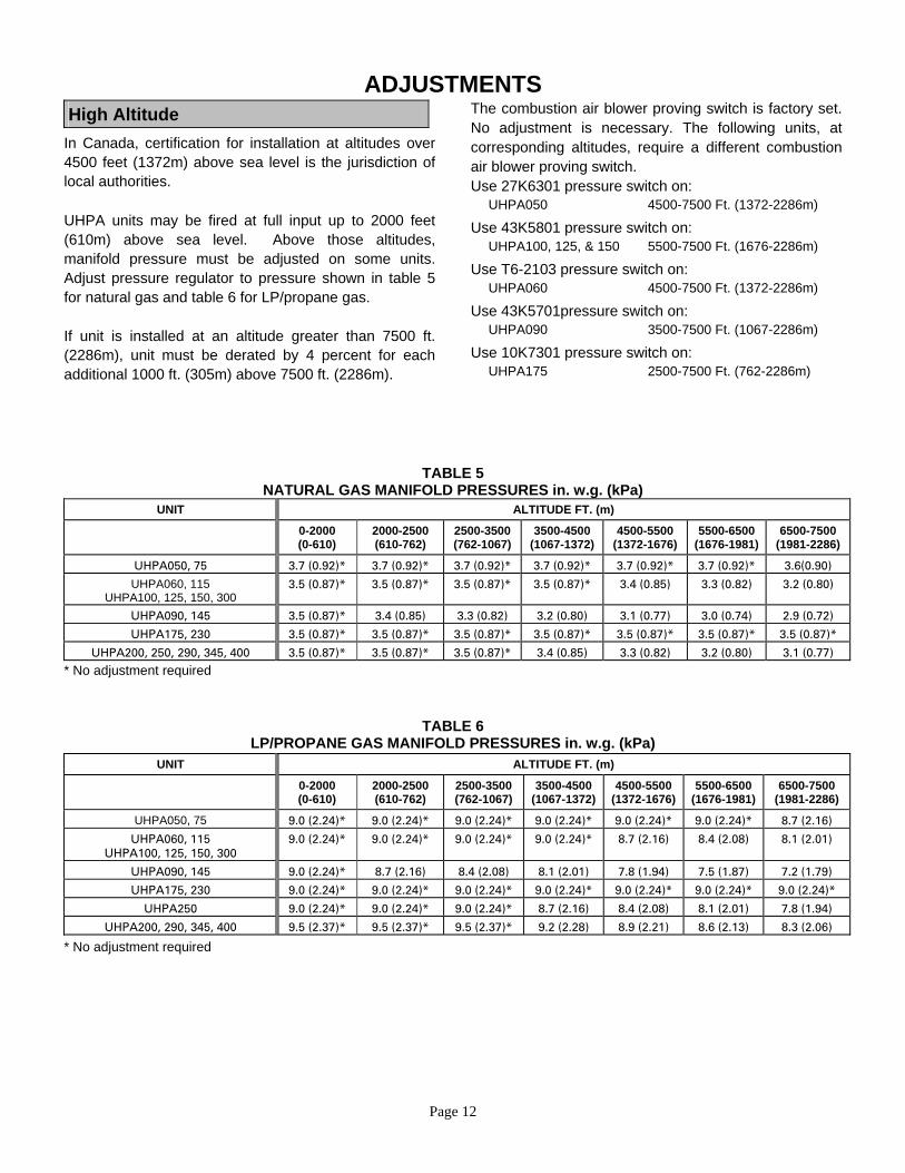
ADJUSTMENTS High Altitude
In Canada, certification for installation at altitudes over 4500 feet (1372m) above sea level is the jurisdiction of local authorities. UHPA units may be fired at full input up to 2000 feet (610m) above sea level. Above those altitudes, manifold pressure must be adjusted on some units. Adjust pressure regulator to pressure shown in table 5 for natural gas and table 6 for LP/propane gas. If unit is installed at an altitude greater than 7500 ft. (2286m), unit must be derated by 4 percent for each additional 1000 ft. (305m) above 7500 ft. (2286m).
The combustion air blower proving switch is factory set. No adjustment is necessary. The following units, at corresponding altitudes, require a different combustion air blower proving switch. Use 27K6301 pressure switch on: UHPA050 4500-7500 Ft. (1372-2286m)
Use 43K5801 pressure switch on: UHPA100, 125, & 150 5500-7500 Ft. (1676-2286m)
Use T6-2103 pressure switch on: UHPA060 4500-7500 Ft. (1372-2286m)
Use 43K5701pressure switch on: UHPA090 3500-7500 Ft. (1067-2286m)
Use 10K7301 pressure switch on: UHPA175 2500-7500 Ft. (762-2286m)
TABLE 5 NATURAL GAS MANIFOLD PRESSURES in. w.g. (kPa)
UNIT ALTITUDE FT. (m) 0-2000
(0-610) 2000-2500 (610-762)
2500-3500(762-1067)
3500-4500 (1067-1372)
4500-5500 (1372-1676)
5500-6500(1676-1981)
6500-7500 (1981-2286)
UHPA050, 75 3.7 (0.92)* 3.7 (0.92)* 3.7 (0.92)* 3.7 (0.92)* 3.7 (0.92)* 3.7 (0.92)* 3.6(0.90)
UHPA060, 115 UHPA100, 125, 150, 300
3.5 (0.87)* 3.5 (0.87)* 3.5 (0.87)* 3.5 (0.87)* 3.4 (0.85) 3.3 (0.82) 3.2 (0.80)
UHPA090, 145 3.5 (0.87)* 3.4 (0.85) 3.3 (0.82) 3.2 (0.80) 3.1 (0.77) 3.0 (0.74) 2.9 (0.72)
UHPA175, 230 3.5 (0.87)* 3.5 (0.87)* 3.5 (0.87)* 3.5 (0.87)* 3.5 (0.87)* 3.5 (0.87)* 3.5 (0.87)*
UHPA200, 250, 290, 345, 400 3.5 (0.87)* 3.5 (0.87)* 3.5 (0.87)* 3.4 (0.85) 3.3 (0.82) 3.2 (0.80) 3.1 (0.77) * No adjustment required
TABLE 6 LP/PROPANE GAS MANIFOLD PRESSURES in. w.g. (kPa)
UNIT ALTITUDE FT. (m) 0-2000
(0-610) 2000-2500 (610-762)
2500-3500(762-1067)
3500-4500 (1067-1372)
4500-5500 (1372-1676)
5500-6500(1676-1981)
6500-7500 (1981-2286)
UHPA050, 75 9.0 (2.24)* 9.0 (2.24)* 9.0 (2.24)* 9.0 (2.24)* 9.0 (2.24)* 9.0 (2.24)* 8.7 (2.16)
UHPA060, 115 UHPA100, 125, 150, 300
9.0 (2.24)* 9.0 (2.24)* 9.0 (2.24)* 9.0 (2.24)* 8.7 (2.16) 8.4 (2.08) 8.1 (2.01)
UHPA090, 145 9.0 (2.24)* 8.7 (2.16) 8.4 (2.08) 8.1 (2.01) 7.8 (1.94) 7.5 (1.87) 7.2 (1.79)
UHPA175, 230 9.0 (2.24)* 9.0 (2.24)* 9.0 (2.24)* 9.0 (2.24)* 9.0 (2.24)* 9.0 (2.24)* 9.0 (2.24)*
UHPA250 9.0 (2.24)* 9.0 (2.24)* 9.0 (2.24)* 8.7 (2.16) 8.4 (2.08) 8.1 (2.01) 7.8 (1.94)
UHPA200, 290, 345, 400 9.5 (2.37)* 9.5 (2.37)* 9.5 (2.37)* 9.2 (2.28) 8.9 (2.21) 8.6 (2.13) 8.3 (2.06)
* No adjustment required
Page 13
Gas Flow To check for proper gas flow to the combustion chamber, determine the Btu input from the appliance rating plate. Divide this input rating by the Btu per cubic feet of available gas. Result is the required number of cubic feet per hour. Determine the flow of gas through the gas meter for two minutes and multiply by 30 to get the hourly flow of gas.
Gas Pressure
1- Check gas line pressure with unit firing at maximum
rate. A minimum of 5.0" w.c. for natural gas or 11.0" w.c. for LP/propane gas should be maintained for proper unit operation.
2- After line pressure has been checked and adjusted,
check manifold pressure. Correct manifold pressure to that specified on the unit rating plate. See figures 8, 9, and 10 for gas pressure adjustment screw location. A natural gas to LP/propane gas changeover kit is required to convert unit. Refer to installation instructions provided with changeover kit for conversion procedure.
Limit Control / Auxiliary Limit The limit control switch(es) are factory set and are not ield adjustable. f Louver Vane Adjustment
The UHPA series unit heaters are provided with movable louver vanes. By adjusting them, air flow from the unit can be directed down, straight, up or any combination of these. WARNING-DO NOT CLOSE the bottom three louvers on SEP or premature failure to the heat exchanger can
ccur. o Combustion Air Pressure Switch
This pressure switch checks for proper combustion air blower operation before allowing an ignition trial. The switch is factory set and no field adjustment is necessary.
Page 14
SERVICE CAUTION - Turn off gas and electrical power to unit before performing any maintenance or service operations on this unit. Remember to follow lighting instructions when putting unit back into operation after ervice or maintenance. s Burners
1- Periodically examine burner flames for proper appearance during the heating season.
2- Before each heating season examine the burners for any deposits or blockage that may have occurred.
3- Clean burners as follows: a-Turn off both electrical and gas supplies to unit. b-Disconnect gas supply piping, high tension and sensor leads. Remove gas manifold. Remove burner tray. c-Clean burners as necessary. Make sure that burner heads line up properly to ensure flame crossover. Check spark gap on electrode and adjust if required. The gap should be between 0.110 inch and 0.140 inch (2.79mm to 3.56mm). The gap may be checked with appropriately sized twist drills or feeler gauges. d-Reinstall burner tray, gas manifold, high tension and sensor leads. Reconnect gas supply piping. e-Restore electrical power and gas supply. Follow lighting instructions to light unit. Check burner flame.
Flue Passageway and Flue Box The flue passages and flue box should be inspected and cleaned prior to each heating season. The sequence of operation should be as follows: 1- Turn off both electrical and gas supply to unit. 2- Disconnect combustion air blower wiring. 3- Remove screws securing flue box to unit. Remove
flue box. If necessary, remove blower assembly from flue box. Clean flue box with wire brush.
4- There are no flue baffles on UHPA050, 060, 075 or 090 unit heaters. On the remaining models remove baffle retention bracket and flue baffles. Clean flue baffles with wire brush.
5- Remove burners as described in "Burners" section. 6- Clean tubes with a wire brush. 7- Reassemble unit. The combustion air and flue box
gaskets should also be replaced during reassembly. 6- Restore electrical power and gas supply. Follow
lighting instructions to light unit. Check operation of unit.
Combustion Air Blower Under normal operating conditions, the combustion air blower should be checked and cleaned prior to the heating season with the power supply disconnected. Use a small brush to clean blower wheel.
Electrical
1- Check all wiring for loose connections. 2- Check for correct voltage at unit (unit operating). 3- Check amperage draw. Flue and Chimney
Check all vent and vent connector joints for tightness. Ensure that connections are sealed and that there are no blockages.
Failure To Operate
If unit fails to operate check the following: 1- Is thermostat calling for heat? 2- Is main disconnect closed? 3- Is there a breaker tripped or a fuse blown? 4- Is gas turned on at meter? 5- Is manual shutoff valve open? 6- Is unit ignition system in lock out? 7- If unit locks out again, call service technician to
inspect unit. Is pressure switch closed? Obstructed flue will cause unit to shut off at pressure switch. Check flue passage and outlet.
Repair Parts
When ordering repair parts include the complete unit model number listed on the unit rating plate. For example: UHPA060AE-1.
Page 15
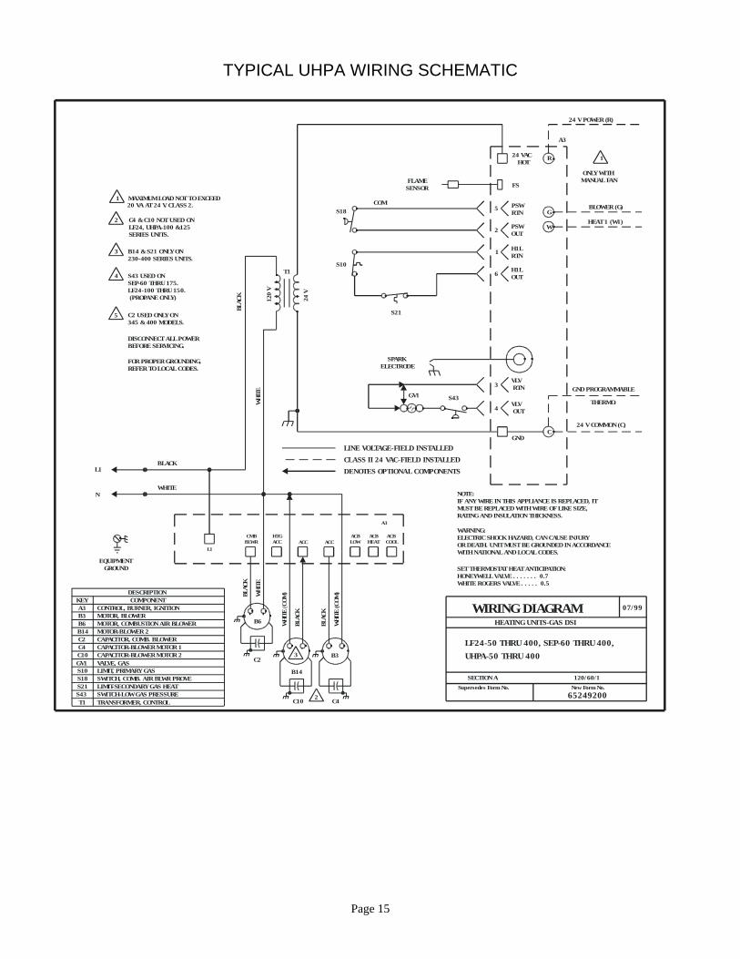
TYPICAL UHPA WIRING SCHEMATIC
MOTOR, COMBUSTION AIR BLOWER
DESCRIPTION
A3B3B6B14C2C4C10GV1S10S18
KEY
S21S43T1
COMPONENTCONTROL, BURNER, IGNITIONMOTOR, BLOWER
MOTOR-BLOWER 2CAPACITOR, COMB. BLOWERCAPACITOR-BLOWER MOTOR 1CAPACITOR-BLOWER MOTOR 2VALVE, GASLIMIT, PRIMARY GASSWITCH, COMB. AIR BLWR PROVELIMIT-SECONDARY GAS HEATSWITCH-LOW GAS PRESSURETRANSFORMER, CONTROL
NOTE:IF ANY WIRE IN THIS APPLIANCE IS REPLACED, IT MUST BE REPLACED WITH WIRE OF LIKE SIZE,RATING AND INSULATION THICKNESS.
WARNING:ELECTRIC SHOCK HAZARD, CAN CAUSE INJURYOR DEATH. UNIT MUST BE GROUNDED IN ACCORDANCEWITH NATIONAL AND LOCAL CODES.
SET THERMOSTAT HEAT ANTICIPATION:HONEYWELL VALVE . . . . . . . 0.7WHITE ROGERS VALVE . . . . .
20 VA AT 24 V. CLASS 2.
2 C4 & C10 NOT USED ON L 24, UHPA-100 &125 F SERIES UNITS.
1 MAXIMUM LOAD NOT TO EXCEED
3 B14 & S21 ONLY ON 230-400 SERIES UNITS.
4 S43 USED ONSEP-60 THRU 175.LF24-100 THRU 150. (PROPANE ONLY)
5 C2 USED ONLY ON345 & 400 MODELS.
DISCONNECT ALL POWERBEFORE SERVICING.
FOR PROPER GROUNDING,REFER TO LOCAL CODES.
WIRING DIAGRAM 07/99
HEATING UNITS-GAS DSI
LF24-50 THRU 400, SEP-60 THRU 400,UHPA-50 THRU 400
SECTION A 120/60/1Supersedes Form No. New Form No.
65249200
ACBCOOL
ACBHEAT
ACBLOWACCACC
HTGACC
CMBBLWR
A3
L1
24V
120
VT1
R
G
W
24 V POWER (R)
BLOWER (G)
HEAT 1 (W1)
1
ONLY WITH MANUAL FAN
24 VACHOT
FS
5
2
1
6
PSWRTN
PSWOUT
H1LRTN
H1LOUT
3
4
CGND
GND PROGRAMMABLE
THERMO.
24 V COMMON (C)
VLVRTN
VLVOUT
FLAME SENSOR
SPARK ELECTRODE
0.5
COMS18
S10
S21
GV1 S43
LINE VOLTAGE-FIELD INSTALLEDCLASS II 24 VAC-FIELD INSTALLEDDENOTES OPTIONAL COMPONENTS
BLAC
K
WHI
TE
WHI
TE(C
OM)
BLAC
K
BLAC
K
WHI
TE(C
OM)
BLACK
WHITE
L1
N
BLAC
K
WH
ITE
EQUIPMENTGROUND
3
2
B6
B3
B14
C2
C10 C4
A3
Page 16
EQUIPMENT LIMITED WARRANTY TWO (2) YEAR COVERAGE EXCLUDED COMPONENTS
The covered equipment and components are warranted for a period of two (2) years from the date of the original unit installation, when installed and operated in accordance with manufacturers recommendations. If, during this period, a covered component fails, a replacement part will be provided, F.O.B. point of shipment. You must pay all other costs of warranty service. Labor involved in diagnostic calls or in removing, servicing, or replacing parts, will not be paid.
The following components are not protected by the warranty: cabinets, cabinet pieces, wiring, and wiring harnesses. REPAIRS All repairs of covered components must be made with authorized service parts. Labor charges resulting from diagnostic calls or service are not covered by this warranty.
EXTENDED CARE OF EQUIPMENT
Your limited warranty provides extended coverage on the components outlined below. The extended warranty coverage begins with the date of the original unit installation and represents the total warranty period for the specific component.
Your new unit must be properly installed, operated, and maintained in accordance with the unit installation, operation, and maintenance instructions provided with each unit. Failure to provide maintenance per instructions may void the warranty.
Heat Exchangers Aluminized - Ten (10) years Stainless steel - Fifteen (15) years A replacement heat exchanger will be furnished or a credit will be allowed (in the amount of the suggested heat exchanger selling price) toward the purchase of an equivalent Armstrong appliance.
WARRANTY PROCEDURE When warranty parts are required: 1- Be prepared to furnish the following
information: a-Complete model and serial number and date of installation. b-An accurate description of the problem.
2-Call your local contractor.
Page 17
WARRANTY LIMITATIONS This warranty is voided if the covered equipment is removed from the original installation site. This warranty does not cover damage or defect resulting from: 1-Equipment installed and operated in a corrosive atmosphere (chlorine, fluorine, salt, or other damaging chemicals). 2-Accident, or neglect or unreasonable use or operation of the equipment, including operation of electrical equipment at voltages other than the range specified on the unit nameplate. 3-Modification, change or alteration of the equipment, except as directed by manufacturer. The furnishing of replacement parts under terms of this warranty will apply to the original warranty period (including any extended warranty period) and will not extend the warranty period.
Manufacturer makes no express warranties other than the warranty specified above. All implied warranties, including the implied warranty of merchantability and fitness for a particular purpose, are limited to the duration of the warranty specified above. Liability for incidental and consequential damage is excluded and is not covered by this warranty. Some states do not allow limitations on the duration of an implied warranty or the exclusion or limitation of incidental or consequential damages, so the limitations or exclusions may not apply to you. This warranty gives you specific legal rights, and you may also have other rights which vary from state to state. Manufacturer shall not be liable for any default or delay in performance under this warranty caused by any contingency beyond its control. NOTE TO CUSTOMER Please complete the information below and retain this warranty for your records and future reference. Unit Model Number: _________________________________________ Serial Number: _____________________ Date: __________________ Installing Contractor: ___________________ Phone: ________________
421 Monroe Street Bellevue, Ohio 44811
1-800-448-5872
Page 18
TEMPLATELocation of Induced Draft Mounting Holes for Rotated Blower
EXISTING HOLE
EXISTING HOLE
EXISTING HOLE
NEW HOLE PATTERN FOR 90° ROTATIONTO LEFT (FACING REAR OF UNIT)
NEW HOLE PATTERN FOR 90° ROTATIONTO RIGHT (FACING REAR OF UNIT)