Embed Size (px)
Citation preview
i
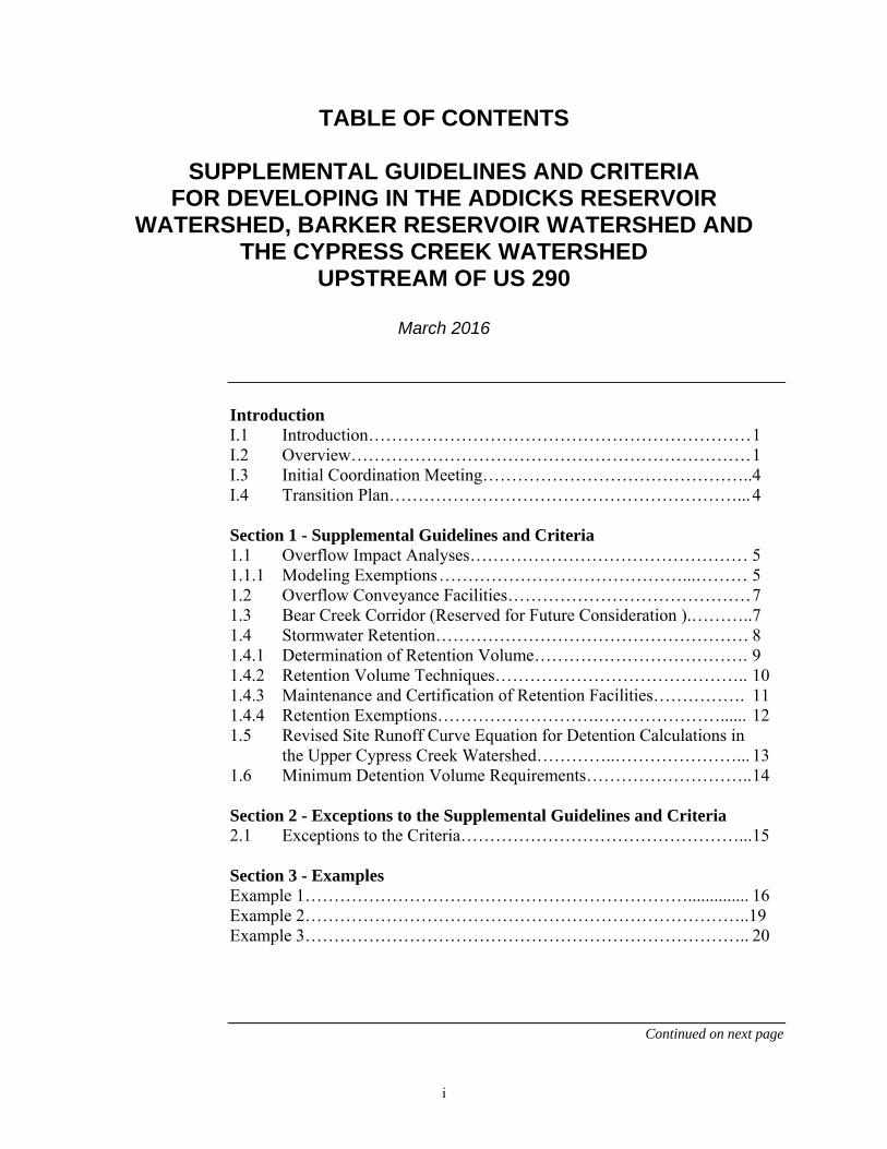
TABLE OF CONTENTS
SUPPLEMENTAL GUIDELINES AND CRITERIA FOR DEVELOPING IN THE ADDICKS RESERVOIR
WATERSHED, BARKER RESERVOIR WATERSHED AND THE CYPRESS CREEK WATERSHED
UPSTREAM OF US 290
March 2016
Introduction
I.1 Introduction………………………………………………………… 1 I.2 Overview…………………………………………………………… 1 I.3 Initial Coordination Meeting………………………………………..4 I.4 Transition Plan……………………………………………………... 4 Section 1 - Supplemental Guidelines and Criteria 1.1 Overflow Impact Analyses………………………………………… 5 1.1.1 Modeling Exemptions ……………………………………...……… 5 1.2 Overflow Conveyance Facilities…………………………………… 7 1.3 Bear Creek Corridor (Reserved for Future Consideration ).………..7 1.4 Stormwater Retention……………………………………………… 8 1.4.1 Determination of Retention Volume………………………………. 9 1.4.2 Retention Volume Techniques…………………………………….. 10 1.4.3 Maintenance and Certification of Retention Facilities……………. 11 1.4.4 Retention Exemptions……………………….…………………...... 12 1.5 Revised Site Runoff Curve Equation for Detention Calculations in
the Upper Cypress Creek Watershed…………..…………………... 13 1.6 Minimum Detention Volume Requirements……………………….. 14 Section 2 - Exceptions to the Supplemental Guidelines and Criteria 2.1 Exceptions to the Criteria…………………………………………... 15 Section 3 - Examples Example 1………………………………………………………….............. 16 Example 2…………………………………………………………………..19 Example 3………………………………………………………………….. 20
Continued on next page

ii
Table of Contents, Continued
Exhibits
Exhibit 1: General Service Area Map Exhibit 2: Region Requiring 2D Modeling for Impact Analyses in the upper Cypress Creek, Addicks Reservoir and Barker Reservoir Watersheds Exhibit 3: Cypress Creek Overflow Depths Exhibit 4: Overflow Region of Higher Depth and Velocity Exhibit 5: Upper and Lower Limits of the 500-ft Wide Corridor Along Bear Creek (U102-00-00) ( Reserved for Future Consideration) Exhibit 6: Retention Volume Service Area Map Exhibit 7: Retention Volume Service Area Watershed Map Exhibit 8: Regional Drainage Plans Exempt from the Retention Volume Criteria Exhibit 9: Area of Application for the Revised Upper Cypress Creek Site Runoff Curve Equations for Detention Storage Calculations

1
Introduction
I.1 Introduction These supplemental guidelines and criteria to the Harris County Flood
Control District's (HCFCD) Policy Criteria and Procedures Manual (PCPM) are intended to provide direction for the engineering community and HCFCD staff to comply with the HCFCD no adverse impact policy associated with management of stormwater runoff from land development and infrastructure projects in the Cypress Creek watershed upstream of US 290 (upper Cypress Creek), Addicks Reservoir and Barker Reservoir watersheds within Harris County. A general service area map for these supplemental criteria is provided on Exhibit 1. Current HCFCD policy, criteria, procedures, and requirements for land development and infrastructure projects will continue to apply except as noted with these supplemental guidelines and criteria.
This supplement is prompted by unique hydrologic and hydraulic conditions that exist in the western region of Harris County. These supplemental guidelines and criteria are intended to address:
Management of the occasional overflow of runoff that occurs from the upper Cypress Creek watershed to the Addicks Reservoir and Barker Reservoir watersheds during moderate to heavy rainfall events. It is estimated that the overflow initiates between the 20 percent (5-year) and 10 percent (10-year) probability storm events.
Mitigation of increases in runoff volume draining into the Addicks and Barker reservoirs that may be attributable to future development.
Reflection in the detention calculations of the higher rate of stormwater storage that is occurring within the upper Cypress Creek watershed under the existing rural and minimally developed conditions.
I.2 Overview These supplemental guidelines and criteria include information related to:
Impact analyses demonstrating no adverse impacts associated with development of properties or infrastructure projects that are affected by, or contribute to, the Cypress Creek overflow.
Dedication and construction of overflow conveyance facilities.
Stormwater runoff volume control (retention volume) for development of properties located within the Addicks Reservoir and Barker Reservoir watersheds, as well as a portion of the upper Cypress Creek watershed upstream of and adjacent to locations where the overflow occurs.
Continued on next page

2
Introduction, Continued
I.2 Overview (continued)
Revised Site Runoff Curve equations for detention calculations in the upper Cypress Creek watershed.
Revised minimum detention requirements within the upper Cypress Creek watershed.
The following table shows which of these guidelines and criteria apply to which watershed. Additionally, Exhibits 1-9 illustrate the area of application for these guidelines and criteria.
Continued on next page

3
Introduction, Continued
I.2 Overview (continued)
Table 1: Application of the Supplemental Drainage Guidelines and Criteria
Supplemental Guidelines and Criteria1
Upper Cypress Creek
Watershed2
Addicks Reservoir
Watershed2
Barker Reservoir
Watershed2
Overflow Impact Analyses3 (Section 1.1) x x x
Overflow Conveyance Facilities4
(Sections 1.2) x x
Bear Creek Corridor5
(Section 1.3) x
Stormwater Retention for New Development (Section 1.4)
x6 x x
Revised Site Runoff Curve Equations7
(Section 1.5) x
Revised Minimum Detention
Volume Requirements (Section 1.6)
x
Notes:
1. Exceptions to the supplemental guidelines and criteria are presented in Section 2.1.
2. These guidelines and criteria are applicable to those portions of the Addicks Reservoir, Barker Reservoir and upper Cypress Creek Watersheds located in Harris County.
3. Overflow impact analyses will be required within limited regions of the applicable watersheds. Please see Section 1.1 and Exhibit 2 for information regarding where and for what development conditions an overflow impact analysis will be required.
4. Dedication of overflow conveyance facilities will be required within limited regions of the applicable watersheds. Please see Sections 1.2, as well as Exhibits 3 and 4 for additional information regarding the aerial extent of the overflow, as well as regions of higher depth and velocity within the path of the 1% overflow footprint.
5. Reserved for future consideration.
6. Stormwater retention in the upper Cypress Creek watershed will be required upstream of Katy-Hockley Road. The portion of the upper Cypress Creek watershed located downstream of Katy-Hockley Road will not be required to provide stormwater retention. Please see Exhibits 6 and 7 for additional information.
7. The revised site runoff curves for the upper Cypress Creek watershed shall be used for Method 1 and 2 detention volume calculations and sizing detention facility outfall structures (See PCPM Sections 6.10 and 6.11).

4
Introduction, Continued
I.3 Initial Coordination Meeting
It is essential that the engineer meet with the HCFCD during the Preliminary Assessment (PCPM, Section 2.8.4) and prior to initiating any technical hydrologic investigation for new or modified projects. The purpose of the meeting is for the design engineer to describe the methodology and types of facilities that are proposed to address the requirements outlined within these supplemental guidelines and criteria, obtain concurrence from HCFCD of the proposed analytical approach, and confirm understanding of the requirements. Documentation by the engineer of the understandings and concurrence by the HCFCD is strongly recommended.
I.4 Transition Plan
All supplemental criteria in this document are important for the successful design, construction and function of HCFCD facilities. The HCFCD encourages using these supplemental criteria as soon as practical. Effective dates for these criteria are provided below and are based on project status on the day these criteria are adopted by Commissioners Court.
Table 2: Transition Period for the Supplemental Drainage Guidelines and Criteria
Project Status on Day of Adoption* Immed-iately
Three Months
Two Years
Stage 1, Initiation (New Project) No evidence of project initiation such as a HCFCD response letter or a Stage 2 submittal.
X
Stage 2 - Drainage or Design Report (Feasibility or Planning Phase)
Not Submitted - Stage 1 completed and report not submitted to HCFCD.
X
Submitted - Report submitted to HCFCD for approval as confirmed by the One Stop Shop submission records or a complete preliminary plat application as confirmed by a CPC-101 form or equivalent.
X
See PCPM Section 2.8 for a description of the phases of review and coordination with the HCFCD. Later stages shall be conducted in accordance with existing HCFCD guidelines.

5
Section 1 – Supplemental Guidelines and Criteria
1.1 Overflow Impact Analyses
Projects located in areas that are affected by or influence the Cypress Creek Overflow must perform an overflow impact analysis. The region in Harris County requiring overflow impact analyses include portions of the upper Cypress Creek watershed, Addicks Reservoir watershed, and a small portion of the Barker Reservoir watershed as shown on Exhibit 2. An overflow impact analysis will not be required for those portions of the upper Cypress Creek, Addicks Reservoir and Barker Reservoir watersheds that are not affected by the Cypress Creek Overflow. Additional discussion and guidance regarding overflow impact analyses can be found in the document titled Modeling Guidelines in Support of Development Impact Analyses to Establish No-Adverse Impacts in the Overflow Areas of the Addicks and Barker Reservoir Watersheds, a supplement to the HCFCD Hydrology and Hydraulics Manual.
1.1.1 Modeling Exemptions
Projects are generally exempt from performing overflow impact analyses if all of the following conditions apply:
1. The project overlaps with less than 10 acres of land that is subject to inundation by the 1 percent (100-year) overflow.
2. The project is not part of a larger master-planned community that overlaps with more than 10 acres of property that is subject to inundation by the 1 percent (100-year) overflow.
3. The project is located within an area that experiences inundation depths of 12-inches or less during a 1 percent (100-year) overflow occurrence. Coordination with HCFCD will be required to determine depth of overflow at applicant’s project site.
4. The project will have limited on-site drainage improvements and relatively small amounts of impervious cover. Impervious cover must be less than or equal to 15 percent of the site, including drainage facilities.
5. The project will have minimal fill below the base flood elevation. Table 3 provides the maximum allowable fill footprint for small projects exempt from overflow impact analyses. For projects less than 3 acres in size, a maximum fill surface area of 3,000 square feet below the base flood elevation will be permissible.
Continued on next page

6
Section 1 – Supplemental Guidelines and Criteria, Continued
1.1.1 Modeling Exemptions (continued)
If a base flood elevation is not available, coordinate with HCFCD to obtain the best available information regarding the 1 percent water surface elevation across the project site.
Table 3: Maximum Allowable Fill Surface Area for Small Projects that Qualify for Exemption from Performing Overflow
Impact Analyses
1 ac 3,000 ft2
2 ac 3,000 ft2
3 ac 3,000 ft2
4 ac 4,000 ft2
5 ac 5,000 ft2
6 ac 6,000 ft2
7 ac 7,000 ft2
8 ac 8,000 ft2
9 ac 9,000 ft2
9.9 ac 9,900 ft2
Development Size Maximum Fill Surface Area *
The maximum fill surface area is based on total project area located within the
1 percent (100-year) overflow. The modeling exemption is permissible for those properties located within areas that experience inundation depths less than or equal to 12 inches during the 1 percent (100-year) overflow.
These exemptions attempt to simplify the required analyses for small projects and those projects that overlap with relatively small, shallow areas of the overflow; however, circumstances may exist that would still require a detailed overflow impact analysis using numerical models. Therefore, small developments, as well as those projects that overlap with the 1 percent (100-year) overflow fringe, are encouraged to meet with HCFCD prior to plan development.

7
Section 1 – Supplemental Guidelines and Criteria, Continued
1.2 Overflow Conveyance Facilities
New development will be required to dedicate a public drainage easement for any property used to construct facilities that convey the overflow. Property dedication, preferably in fee to the HCFCD, will also be required across areas of higher depth and velocity for the overflow that are located north and west of the headwaters of Bear Creek (Channel U102-00-00) and north of FM 529 (see Exhibit 4). The exact location and size of the required property dedication upstream of Katy-Hockley Road will be determined based on the proposed development layout and detailed modeling results. A coordination meeting with the HCFCD Watershed Management Department prior to submitting any site plans or drainage reports is required.
The HCFCD will accept overflow management plans that include overflow conveyance facilities that discharge the overflow in a manner consistent with pre-project conditions. Regardless of how the overflow is discharged from a new development, no adverse impact must be demonstrated through the performance of an overflow impact analysis, as discussed in Section 1.1.
1.3 Bear Creek Corridor
Reserved for future consideration.

8
Section 1 – Supplemental Guidelines and Criteria, Continued
1.4 Stormwater Retention (continued)
In order to manage increased stormwater runoff volume from new developments into Addicks and Barker reservoirs, stormwater retention will be required for new development within the Addicks Reservoir and Barker Reservoir watersheds, as well as the upper Cypress Creek watershed west of Katy-Hockley Road (Exhibits 6 and 7) for projects greater than 1 acre in size. Stormwater retention will be used to capture a portion of stormwater runoff leaving new developments and hold it for an indefinite period of time. Low impact development and green infrastructure techniques such as reuse, infiltration and evaporation can be used to dispose of the retained stormwater, as well as controlled release into a receiving drainage facility under certain conditions.
The PCPM requires use of detention to temporarily store stormwater in order to restrict peak discharge from new developments to the pre-project peak discharge; however, the use of detention does not address the volume of stormwater draining from new developments. Applicants with new projects in the upper Cypress Creek (upstream of Katy-Hockley Rd), Addicks Reservoir and Barker Reservoir watersheds will be required to comply with stormwater retention and stormwater detention criteria. Stormwater retention must be provided in the same watershed as the proposed project.
The applicant is expected to comply with all other current Harris County and HCFCD criteria and policies for stormwater management and mitigation of land development and infrastructure projects (HCFCD PCPM and Harris County Regulations), including the minimum detention storage requirements provided in Section 6.9 of the PCPM and Section 1.6 of these supplemental guidelines and criteria.
A portion of the captured detention volume can be counted as both detention volume and retention volume provided the following conditions are met:
The retention volume is controlled and disposed of or released in accordance with Section 1.4.2, Retention Volume Techniques, of this document.
The detention volume provided by the detention basin is increased by 10%.
The following discussion provides criteria on how to determine the increased volume of stormwater runoff to be mitigated, as well as techniques that can be used to provide the required retention.

9
Section 1 – Supplemental Guidelines and Criteria, Continued
1.4.1 Determination of Retention Volume
Refer to the PCPM for the impervious cover values for common land use categories (PCPM Section 3.5.1), along with the depth of direct runoff (PCPM Section 3.6.7), needed to calculate the runoff volume. Provide a detailed description of the area to be developed that includes acreages and maps of existing and post-development land use/land cover types.
The minimum retention rate shall be no less than 0.1 acre-feet per acre with a detailed analysis. Absent a detailed analysis, the following retention volume is required to mitigate stormwater runoff volume:
Table 4: Minimum Retention Storage Rates Required if Detailed Calculations are Not Performed
Land Use*
Runoff Depth
(inches) Retention Rate (acre-feet/acre)
Residential - Small Lot (≤ ¼ ac) 2.1 0.17
Light Industrial/Commercial 2.9 0.24
High Density Commercial, Business, Industrial, or Apartments 3.9 0.32
Refer to the PCPM Section 3.5.1 for the impervious cover values for common land use categories, and to the PCPM Section 3.6.7 for the depth of direct runoff.
Certain Low Impact Development (LID) and Green Infrastructure (GI) techniques may be used to reduce stormwater runoff volume. The use of LID and GI practices may be considered in the retention volume calculations. However, LID and GI techniques must comply with the Harris County Low Impact Development and Green Infrastructure Design Criteria for Storm Water Management (LID and GI Manual). In accordance with Section 2.3 of the LID and GI Manual, there is the potential to reduce the required minimum detention rate for new development by 0.20 acre-feet per acre if GI techniques are employed.
Include a clear explanation describing how the retention volume was determined in the Impact Analysis Report. Two examples of approaches are in Section 3 of these criteria.

10
Section 1 – Supplemental Guidelines and Criteria, Continued
1.4.2 Retention Volume Techniques
Capture and retain the stormwater runoff to satisfy the retention volume mitigation requirement. Acceptable methods for satisfying the retention volume requirement include but are not limited to:
1. Demonstrate how the stored retention volume will be drained through reuse methods such as irrigation, or a combination of reuse, infiltration, evaporation, and/or controlled release techniques.
2. Contribute funds to a conservation area, approved by the HCFCD, dedicated to restoring prairie grasslands in the watershed on an acre-per-acre basis. This could take the form of a third-party agreement that outlines the contribution.
It is essential that the applicant meet with the HCFCD prior to participating in a prairie restoration program. The meeting will be used to discuss criteria that will be required by HCFCD to gain approval for prairie restoration programs as stormwater runoff volume mitigation facilities. Requirements will include:
a. Development of a detailed planting plan that includes suitable native plant cover.
b. A description of the restoration protocols to be used, as well as a long-term management plan that ensures retention volume benefits are achieved and maintained in perpetuity.
3. Controlled release into a receiving stream, or drainage system that outfalls into a HCFCD channel, is permissible unless the Harris County Flood Control District website: (http://www.hcfcd.org) indicates that stormwater may not be released into the outfall channel. HCFCD will develop and implement a communication system in coordination with the Corps of Engineers, Galveston District that provides information to retention basin owners, engineers, and operators regarding the release of stormwater into the outfall channel.
a. For the upper Cypress Creek watershed west of Katy-Hockley Road, the factors affecting the release of stormwater include current and forecasted water levels in Cypress Creek and rainfall forecasts that indicate an overflow to the Addicks Reservoir watershed may occur.
b. For Addicks Reservoir and Barker Reservoir watersheds, the factors include current and forecasted water levels in the reservoirs, release rates from the reservoirs, and rainfall forecasts.
Continued on next page
11
Section 1 – Supplemental Guidelines and Criteria, Continued
1.4.2 Retention Volume Techniques (continued)
c. Coordinate the discharge control method from the retention basin with the HCFCD. Options include valves, gates, pumps, etc. that are operated manually or are automated.
4. The applicant may pay a fee to purchase retention volume within a regional stormwater volume mitigation basin in lieu of constructing on-site retention volume measures if such a regional facility becomes available and is approved by the HCFCD.
5. Pumped detention facilities are required to drain at least 50 percent of the detention volume by gravity. The additional retention volume needed for runoff volume mitigation can be added to the pumped detention volume, and will not increase the volume of stormwater that would be required to drain through a gravity outfall. However, the retention volume must be managed using the runoff volume mitigation techniques 1and 3 listed above.
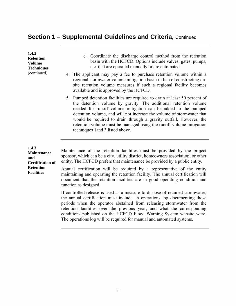
1.4.3 Maintenance and Certification of Retention Facilities
Maintenance of the retention facilities must be provided by the project sponsor, which can be a city, utility district, homeowners association, or other entity. The HCFCD prefers that maintenance be provided by a public entity.
Annual certification will be required by a representative of the entity maintaining and operating the retention facility. The annual certification will document that the retention facilities are in good operating condition and function as designed.
If controlled release is used as a measure to dispose of retained stormwater, the annual certification must include an operations log documenting those periods when the operator abstained from releasing stormwater from the retention facilities over the previous year, and what the corresponding conditions published on the HCFCD Flood Warning System website were. The operations log will be required for manual and automated systems.

12
Section 1 – Supplemental Guidelines and Criteria, Continued
1.4.4 Retention Exemptions
Stormwater retention will not be required under the following conditions:
For only one single family residence where no major changes in existing conditions are proposed and it is not part of a larger development project.
For developments less than or equal to one acre.
For new developments in the upper Cypress Creek watershed adjacent to or upstream of the overflow that construct drainage facilities with a design peak discharge rate for the 1 percent (100-year) and 10 percent (10-year) events at or below the pre-project 20 percent (5-year) discharge rate. It is anticipated that the Cypress Creek floodplain will have sufficient capacity to accommodate the pre-project 20 percent (5-year) flow rate without overflowing into the Addicks Reservoir watershed.
For large project areas, 5-year flow rates can be determined using the FEMA effective HEC-HMS models.
For small to moderate projects (less than 640 acres in size), peak discharge rates can be calculated for the 20 percent (5-year) event using the same equation that is provided in Section 3.3 of the PCPM:
Q = bAm
An m-value of 0.823 will be used for drainage areas greater than 20 acres, and an m-value of 1.0 will be used for drainage areas less than 20 acres. Table 5 provides the b-values that will be used in the equation.
Table 5: 5-Year Site Runoff Curve “b” Parameter
Impervious Cover
5-Year (20% Annual Exceedance
Probability)
<=20 acres >20 acres
0% 1.2 1.6
10% 1.5 0.7
20% 1.8 1.8
30% 2.3 1.9
40% 2.7 2
Continued on next page

13
Section 1 – Supplemental Guidelines and Criteria, Continued
1.4.4 Retention Exemptions (continued)
A ponding adjustment of the standard Harris County site runoff curves is required for estimating undeveloped peak runoff rates for small to moderate areas (areas less than 640 aces) in the upper Cypress Creek watershed, with the exception of the Mound Creek drainage area (see Exhibit 9), for the design of detention facilities. Please see Section 1.5 for more information about the use of ponding adjustment factors.
1.5 Revised Site Runoff Curve Equations for Detention Calculations in the Upper Cypress Creek Watershed
Section 3.3 in the PCPM provides an equation that is used to determine peak discharge rates for small to moderate drainage areas (areas less than 640 acres in size) for the 10-year and 100-year storm events:
Q = bAm
This equation can also be used to calculate 5-year discharge rates for small to moderate drainage areas, which is not included in the PCPM but is discussed in Section 1.4.4 of this document.
An adjustment to the standard Harris County site runoff curves is required for estimating existing peak runoff rates for small to moderate areas (areas less than 640 aces) in the upper Cypress Creek watershed, with the exception of the Mound Creek drainage area (see Exhibit 9), for the design of detention facilities. The following ponding adjustment should be used:
Upper Cypress Creek Modified Site Runoff Equation: Q = p*bAm
p = ponding adjustment factor
If percent impervious (IMP) ≥40%, p = 1.0
If percent impervious (IMP) < 40%, see the ponding equations on the following page.
For locations west of Katy-Hockley Road, excluding the Mound Creek watershed (Exhibit 9), use the following equations to calculate the ponding adjustment factor:
5-year event: p = 0.24 + 0.0190*(IMP)
10-year event: p = 0.33 + 0.0168*(IMP)
100-year event: p = 0.54 + 0.0115*(IMP)
For locations between Fry Road and Katy-Hockley Road (Exhibit 9), use the following equations to calculate the ponding adjustment factor:
5-year event: p = 0.28 + 0.0220*(IMP)
10-year event: p = 0.36 + 0.0181*(IMP)
100-year event: p = 0.57 + 0.0122*(IMP)
Continued on next page

14
Section 1 – Supplemental Guidelines and Criteria, Continued
1.5 Revised Site Runoff Curve Equations for Detention Calculations in the Upper Cypress Creek Watershed (continued)
An example of how to use the ponding adjustment factor is included in Section 3 of these criteria.
Standard Harris County site runoff curve equations should be used when designing drainage infrastructure other than detention facilities, such as interceptor channels around the perimeter of a property.
1.6 Minimum Detention Volume Requirements
Minimum detention volume requirements used to mitigate peak discharge rates from new developments within the upper Cypress Creek watershed, including the Mound Creek Watershed, are revised as follows:
The volume as calculated using Method 1 or 2 as described in Sections 6.10 and 6.11 of the PCPM, but not less than 0.65 acre-feet per acre of new development, or as defined in a watershed with an adopted regional plan.
The volume as calculated using the Optional Project Routing Technique or the Method 3 Technique as described in Sections 3.7 and 6.12 of the PCPM, but not less than 0.55 acre-feet per acre of new development.
These minimum values supersede the minimums in Section 6.9.4 of the PCPM, except for minimum rates for developed green areas and development with impervious cover less than 15%.

15
Section 2 – Exceptions to the Supplemental Guidelines and Criteria
2.1 Exceptions to the Criteria
Under certain circumstances, these supplemental guidelines and criteria will not be applicable. Those circumstances include:
In the event a Regional Overflow Management Plan is defined and formally adopted by Harris County Commissioner’s Court, the applicant will comply with the terms of that plan.
Projects with a master impact study or master drainage plan approved by the HCFCD prior to adoption of these criteria are exempt from these new requirements and may continue to develop under the same previously approved drainage criteria provided approval of the master plan is current and has not expired (see PCPM Section 2.3.5, Signature Expiration).
Properties located in the upper Cypress Creek watershed must comply with PCPM Section 2.15, Regional Flood Control Projects, and provide retention volume sufficient to comply with Section 1.4 of these criteria.
Properties located within the boundaries of the Upper Langham Creek Capital Improvement and Impact Fee Utilization Plan, which is shown on Exhibit 8, are exempt from these supplemental guidelines and criteria.
Properties located within the boundaries of the Langham Creek regional project that was adopted by Harris County Commissioners Court in March 1986, which are shown on Exhibit 8, are exempt from these supplemental guidelines and criteria.
Any Harris County road, bridge or park project may adhere to these supplemental criteria. In the event a Harris County road, bridge or park project elects not to participate in the supplemental criteria, that project will continue to comply with the requirements of the PCPM.

16
Section 3 - Examples
Example 1 Retention Volume Calculation
Project Size: 500 acres
Project Location: Addicks Reservoir Watershed
Documentation provided: Aerial photography of land cover
Summary of existing land use
Proposed land plan and written description
(450 acres of residential development with a gross lot density of 2.3 units/acre and 50 acres of commercial development)
Peak Flow Rate Impact Analysis (Detention)
The HCFCD Method 3 for detention volume calculations was used to determine the appropriate detention volume to mitigate increases in peak discharge rates from the development. The total detention rate was calculated to be 0.55 acre-feet/acre to control peak discharge rates from the development for the 10 percent (10-year) and 1 percent (100-year) annual chance storm events. Detention volume = 275 acre-feet.
Stormwater Retention Volume Analysis (Based on information provided in Sections 3.5 and 3.6 of the PCPM)
The approach for this analysis was to match the impervious cover and runoff depths provided in the PCPM with the existing and proposed land uses at the project location, and to calculate the stormwater runoff volume that will need to be mitigated. Doing so results in the following findings:
10% 1% 10% 1%
Rangeland 0 3.5 7.9 200 58.3 131.7
Grasslands 0 3.5 7.9 50 14.6 32.9
Agriculture 0 3.5 7.9 250 72.9 164.6
Total 500 145.8 329.2
10% 1% 10% 1%
1/3 Ac Residential 30 4.6 9.3 250 95.8 193.8
1/4 Ac Residential 40 4.9 9.7 105 42.9 84.9
1 Ac Residential 20 4.2 8.8 105 36.8 77.0
Detention Facilities 100 7.1 12.4 40 23.7 41.3
Total 500 199.1 397.0
Runoff Volume (ac‐ft)
Runoff Volume (ac‐ft)
Runoff Depth (in)
Existing Land Use
Impervious
Cover (%)
Project
Drainage
Area (Ac)
Proposed Land Use
Impervious
Cover (%)
Runoff Depth (in)Project
Drainage
Area (Ac)
Continued on next page

17
Section 3 - Examples, Continued
Example 1 Retention Volume Calculation (continued)
Change in Runoff 10% 53.3
Volume (Acre‐Feet) 1% 67.8
Retention Volume
Required (acre‐feet) 67.8
Retention Volume
Rate (acre‐feet/acre) 0.14
The 0.14 acre-ft/acre is less than the default value of 0.17 acre-feet/acre. A retention volume of 67.8 acre-feet of stormwater runoff will be managed for the 500-acre development.
Note: The development is retaining 0.14 acre-feet of stormwater for each acre of development because detailed calculations were performed to determine a suitable storage coefficient for runoff volume mitigation. Had this not been done, the development would have been required to retain 0.17 acre-feet of stormwater per acre of development.
Stormwater Mitigation Facility Design and Operation
The developer elects to use a portion of the detention volume to meet retention requirements. The basin will be designed to drain into Bear Creek using gravity flow through two outfall pipes. One will be a gated outfall pipe installed at the basin flow line and will be used to regulate release of the retention volume (67.8 acre-feet) from the detention basin during those times when retention release is not permitted. The second outfall pipe will be installed at an elevation above the retention storage elevation in the combined stormwater management facility and will allow free discharge into the receiving stream.
In accordance with section 1.4 of this document (Stormwater Retention) the detention storage provided by the basin will be increased by 10% because a portion of the detention storage will also serve as runoff volume mitigation. A storage volume of 302.5 acre-feet will be provided in the combined retention/detention facility (275 acre-feet * 1.1 = 302.5 acre-feet). The combined detention and retention system will be designed so that the combined discharge from both pipes does not exceed allowable limits. Additionally, the basin and outfall system will be designed such that the capacity of the detention basin isn’t exceeded for the 24-hour 1% annual chance design storm event when the lower pipe used to regulate the retention volume is closed.
A schematic of the combined detention facility is shown on the following page.
Continued on next page

18
Section 3 - Examples, Continued
Example 1 Retention Volume Calculation (continued)
Conceptual Illustration of the Combined
Detention and Retention Facility
The basin will be maintained by a municipal utility district, which will monitor the retention release conditions on the Harris County Flood Warning System website.
If the developer elected to construct segregated detention and retention facilities, the developer would have constructed one detention basin providing 275 acre feet of storage. A separate retention facility would have been constructed with a storage volume of 67.8 acre feet.
The outfall system from the detention basin would have been designed such that discharge from the detention basins did not exceed the allowable limit for the 10% and 1% storm events. The outfall for the retention facility would have been designed in accordance with Section 1.4.2

19
Section 3 - Examples, Continued
Example 2
Project size: 125 acres
Project Location: Upper Cypress Creek Watershed
Documentation provided: Aerial photography of land cover
Summary of existing land use
Proposed land plan map and written description
Stormwater Runoff Volume Impact Analysis
Applicant elects to not perform any analysis of retention rate. The default retention rate is set at 0.17 acre-feet/acre for residential development, 0.32 acre-feet/acre of commercial development and 0.24 acre-feet/acre of industrial development.
Retention Rate
Acre‐feet/Acre 10% 1%
High Density Commercial 85 0.32 5 1.60 1.60
Light Industrial 60 0.24 8 1.92 1.92
Residential (1/4 ac lots) 40 0.17 112 19.04 19.04
Combined Total 0.18 125 22.56 22.56
Proposed Land Use
Impervious
Cover (%)
Project Drainage
Area (Ac)
Retention Volume
(Ac‐Ft)
Stormwater Mitigation Facility Design and Operation
The developer elects to provide retention and detention in one combined system. Because a portion of the detention volume will also serve as retention, the minimum detention volume must be increased by 10%. The facility will provide 89.94 acre-feet of storage, for a combined storage rate of 0.715 acre-feet/acre (0.65 acre-feet/ac (minimum detention rate in upper Cypress Creek watershed) * 1.10 = 0.715 acre-feet/acre).
The detention and retention volume will be managed with the use of two interconnected basins. A smaller basin, designed using a storage rate of 0.18 acre-feet/acre of development will be used to manage the retention volume (22.56 acre-feet) and will drain into a larger detention basin through a gated pipe. The larger basin will provide 67.38 acre-feet (89.94 acre-feet - 22.56 acre-feet = 67.38 acre-feet) of storage. Discharge from the larger basin will be released into a HCFCD channel through an outlet pipe designed to restrict discharge from the site to an allowable limit. A shallow swale will be used to connect the two basins in the event the smaller basin holding retained water overfills.
20
Section 3 - Examples, Continued
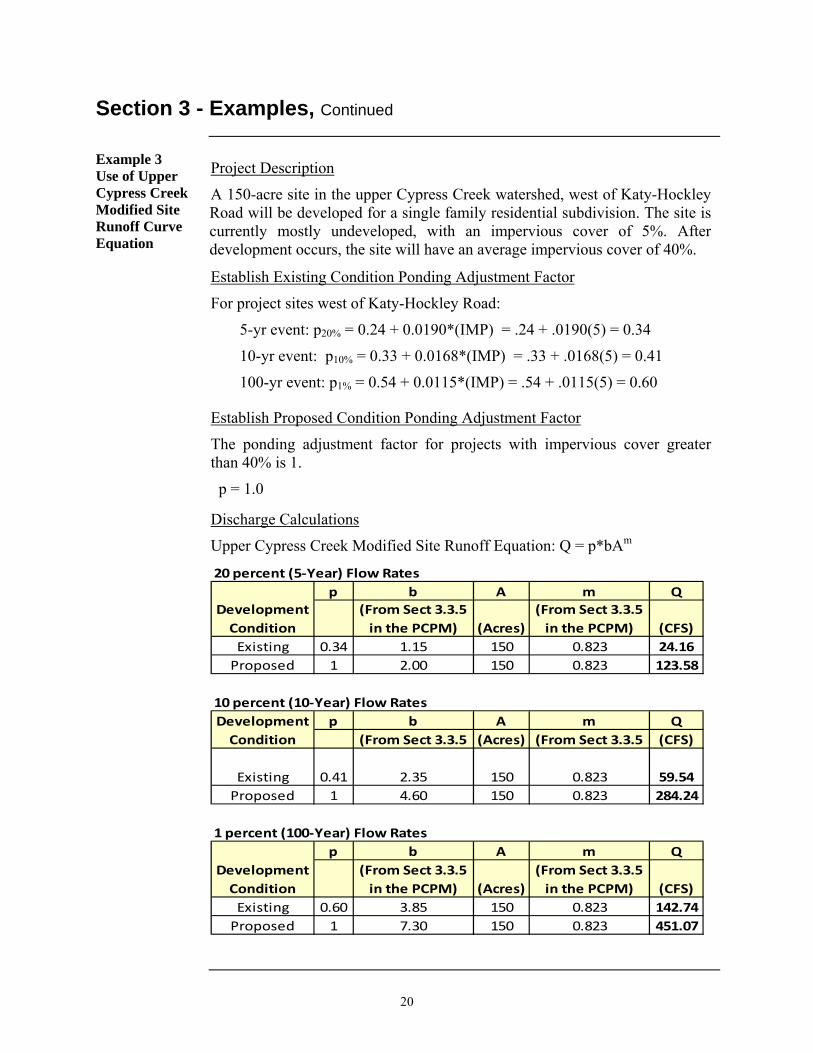
Example 3 Use of Upper Cypress Creek Modified Site Runoff Curve Equation
Project Description
A 150-acre site in the upper Cypress Creek watershed, west of Katy-Hockley Road will be developed for a single family residential subdivision. The site is currently mostly undeveloped, with an impervious cover of 5%. After development occurs, the site will have an average impervious cover of 40%.
Establish Existing Condition Ponding Adjustment Factor
For project sites west of Katy-Hockley Road:
5-yr event: p20% = 0.24 + 0.0190*(IMP) = .24 + .0190(5) = 0.34
10-yr event: p10% = 0.33 + 0.0168*(IMP) = .33 + .0168(5) = 0.41
100-yr event: p1% = 0.54 + 0.0115*(IMP) = .54 + .0115(5) = 0.60
Establish Proposed Condition Ponding Adjustment Factor
The ponding adjustment factor for projects with impervious cover greater than 40% is 1.
p = 1.0
Discharge Calculations
Upper Cypress Creek Modified Site Runoff Equation: Q = p*bAm
p b A m Q
(From Sect 3.3.5
in the PCPM) (Acres)
(From Sect 3.3.5
in the PCPM) (CFS)
Existing 0.34 1.15 150 0.823 24.16
Proposed 1 2.00 150 0.823 123.58
p b A m Q
(From Sect 3.3.5 (Acres) (From Sect 3.3.5 (CFS)
Existing 0.41 2.35 150 0.823 59.54
Proposed 1 4.60 150 0.823 284.24
1 percent (100‐Year) Flow Rates
p b A m Q
(From Sect 3.3.5
in the PCPM) (Acres)
(From Sect 3.3.5
in the PCPM) (CFS)
Existing 0.60 3.85 150 0.823 142.74
Proposed 1 7.30 150 0.823 451.07
20 percent (5‐Year) Flow Rates
Development
Condition
Development
Condition
10 percent (10‐Year) Flow Rates
Development
Condition

HarrisCounty
MontgomeryCounty
WallerCounty
Fort BendCounty
Waller County
BEAR CREEK
S. MAYDE C REEK
HORSEPEN CREEK
MASON CRK.
WESTPARK TOLLWAY
IH-10
HWY 290
IH-45
BE
LTW
AY
8
FM
285
5
SH 249
FM 1960
HWY 6
HA
RD
Y T
OL
L RO
AD
SH 1488
SH 2920
SH
99
FM 529
LOOP 610
HWY 59
SH
288
SH 1093
HWY 90
IH-10
Upper Cypress Creek Watershed
Addicks Reservoir Watershed
Barker Reservoir Watershed
C YPRE
SS
CREEK
WHITE OAK BAYOU
BUFFAL O BAYOU
GREENS B AYOU
LANGHAM CREEK
WILLOW CREEK
LITTLE CYPRESS CREEK
BRAYS BAYOUUPPER BUFFALO BAYOU
SPR ING CREEK
BRAYS BAYOU
SPR ING CREEK
AddicksReservoir
BarkerReservoir
Supplemental Development Guidelines & Criteria
UPPE
R BUF
FALO BAYOU:
0 1.5 3
Miles
General Service Area Map
DATE: MARCH 2016EXHIBIT 1
Addicks Reservoir Watershed
Barker Reservoir Watershed
Upper Cypress Creek Watershed
Supplemental Guidelines & Criteria Service Area
County Boundary

WallerWallerCountyCounty
Boundary for the region where use of the Cypress Creek Overflow 2D model will be required for overflow impact analyses.
Addicks ReservoirAddicks ReservoirWatershedWatershed
Barker ReservoirBarker ReservoirWatershedWatershed
Cypress CreekCypress CreekWatershedWatershed
HarrisHarrisCountyCounty
MOUNDCREEK
HWY 290
HWY 290
FR
YF
RY
CLAYCLAY
FM 529FM 529
FM
362
FM
362
SH
6S
H 6
SH
99
SH
99
TE
LGE
TE
LGE
WW EE SSTT
KA
TY
HO
CK
LEY
KA
TY
HO
CK
LEY
PE
EK
PE
EK
BA
RK
ER
CY
PR
ES
SB
AR
KE
R C
YP
RE
SS
QU
EE
NS
TO
NQ
UE
EN
ST
ON
PO
RT
ER
PO
RT
ER
LLIITTTTLLEE YYOORRKK
MO
UN
DM
OU
ND
SHARPSHARP
FM
2855
FM
2855
HHUU
F FFF
MMEE
IISSTT
E ER R
JARVISJARVIS
GGRR
EEEE
NNHH
OOUU
S SE E
HOUSE HAHLHOUSE HAHL
STOCKDICK SCHOOLSTOCKDICK SCHOOL
GRANT
GRANT
CCYYPPRREESSSSWWOOOODD
MMAASSOO
NN
SK
INN
ER
SK
INN
ER
MU
ES
CH
KE
MU
ES
CH
KE
KA
TY
HO
CK
LEY
CU
T O
FF
KA
TY
HO
CK
LEY
CU
T O
FF
BE
CK
ER
BE
CK
ER
LONGENBAUGHLONGENBAUGH
KEITH HARROWKEITH HARROW
SSPPRRIINNGG
CCYYPPRREESSSS
HEMPSTEAD
HEMPSTEAD
GUMMERTGUMMERT
BBRRIIDDGGEELLAANNDDSS LLAAKKEE
LOUETTA
LOUETTA
BA
UE
RB
AU
ER
CCYYPPRREESSSS NN HHOOUUSSTTOONN
KEITH HARROWKEITH HARROW
LLOOUUEETT TTAA
FM
362
FM
362
FM 529FM 529
MMA A
S SOO
NN
HHUU
FF FFMMEEIISSTTEERR
SSPPRRIINNGG CCYYPPRREESSSS
LONGENBAUGHLONGENBAUGH
LLOONNGGEENNBBAAUUGGHH
FM 529FM 529
KA
TY
HO
CK
LEY
KA
TY
HO
CK
LEY
CYPRESS CREEK
LANGHAM CREEK
LITTLE CYPRESS CR EEK
UPPER BUFFALO BAYOU
BEAR CREEK
SOUTH M AYDE CREEK
HORSEPEN CREEK
HORS
EPEN
CRE
EK/G
ULLY
HORS
EPEN
CRE
EK/G
ULLY
Effective FEMA Floodplains
500 Year Zone
100 Year Zone
Floodway
Watershed Boundary
Region Requiring 2D Modeling
:0 0.5 1
Miles
Region Requiring 2D Modeling for Impact Analyses in the UpperCypress Creek, Addicks Reservoir & Barker Reservoir Watersheds
2012 Aerial Imagery
DATE: March 2016
The roadway data used in this map are derived from the STAR*Map®.STAR*Map is a registered trademark of the Houston-Galveston Area Counciland the Geographic Data Committee.
EXHIBIT 2
Supplemental Development Guidelines & Criteria

WallerCounty
WallerCounty Waller
County
HarrisCounty
FM 529
HWY 290
CYPRESS CREEK
ADDICKSRESERVOIR
BARKER RESERVOIR
WHITE OAK BAYOU
LITTLE CYPRESS CREEK
FR
Y
CLAY
FM 529
FM
36
2S
H 6
PE
EK
WEST
TE
LGE
KA
TY
HO
CK
LEY
QU
EE
NS
TO
N
BA
RK
ER
CY
PR
ES
S
PO
RT
ER
FM
28
55
SHARP
LITTLE YORK
GR
EE
NH
OU
SE
JACKJARVIS
HOUSE HAHL
MO
UN
D
STOCKDICK SCHOOL
KA
TY
HO
CK
LE
Y C
UT
OF
F
LONGENBAUGH
KEITH HARROW
MA
SO
N
GUMMERT
SK
INN
ER
BRIDGELAND LAKE
GROESCHKE
CYPRESS N HOUSTON
FM 529
LONGENBAUGH
SH 99
LONGENBAUGH
KEITH HARROW
CYPRESS CREEK
LANGHAM CREEK
UPPER BUFFALO BAYOU
BEAR CREEK
SOUTHM
AYDE CRE EK
HORSEPEN CREEK/GULLY
Supplemental Development Guidelines & CriteriaWatershed Boundary
0 0.5 1
Miles
: Cypress Creek Overflow Depths
USGS DEM 10mH-GAC Hillshade
DATE: March 2016
The roadway data used in this map are derived from the STAR*Map®.STAR*Map is a registered trademark of the Houston-Galveston Area Counciland the Geographic Data Committee.
1% Cypress Creek Overflow
Depth in Feet
0 - 0.5
0.6 - 1
1.1 - 2
2.1 - 3
EXHIBIT 3
Effective FEMA Floodplains
500 Year Zone
100 Year Zone
Floodway

WallerCounty
HarrisCounty
FM 529
KA
TY
HO
CK
LEY
CYPRESS CREEK
BARKER RESERVOIR
FR
Y
PE
EK
KA
TY
HO
CK
LEY
FM
2855
SHARP
GR
EE
NH
OU
SE
HOUSE HAHL
STOCKDICK SCHOOL
LONGENBAUGH
KEITH HARROW
LONGENBAUGH
SH
99
CYPRESS CREEK
LANGHAM CREEK
BEARCREEK
Supplemental Development Guidelines & CriteriaWatershed Boundary
Overflow Area of Higher Depth& Velocity
0 0.25 0.5
Miles
:Overflow Region of Higher Depth and Velocity
USGS DEM 10mH-GAC Hillshade
DATE: March 2016
The roadway data used in this map are derived from the STAR*Map®.STAR*Map is a registered trademark of the Houston-Galveston Area Counciland the Geographic Data Committee.
1% Cypress Creek Overflow
Depth in Feet
0 - 0.5
0.6 - 1
1.1 - 2
2.1 - 3
EXHIBIT 4
Effective FEMA Floodplains
500 Year Zone
100 Year Zone
Floodway

DATE: March 2016
2012 Aerial Imagery
EXHIBIT 5
Supplemental Development Guidelines & CriteriaUpper and Lower Limits of the 500-ft wide Corridor
Along Bear Creek (U102-00-00)
Reserved for Future Consideration

HarrisCounty
MontgomeryCounty
WallerCounty
Fort BendCounty
Waller County
BEAR CREEK
S. MAYDE C REEK
HORSEPEN CREEK
MASON CRK.
WESTPARK TOLLWAYG
RA
ND
PK
WY
IH-10
HWY 290
IH-45B
ELT
WA
Y 8
FM
285
5
SH 249
FM 1960
HWY 6
HA
RD
Y T
OL
L RO
AD
SH 1488
SH 2920
SH
99
FM 529
LOOP 610
HWY 59
SH
288SH 1093
HWY 90IH-10
CYPR
ESS
CREE
K
UPPER
BUFFALO
BAYOU
LANGHAM CREEK
HWY 290WHITE OAK B AYOU
BUFFALO BAYOU
GREENS BA YOU
WILLOW CREEK
LITTLE CYPRESS CREEK
BRAYS BAYOU
SPRI NG CREEK
BRAYS BAYOU
SPRI NG CREEK
Source: Esri, DigitalGlobe, GeoEye, Earthstar Geographics, CNES/Airbus DS, USDA, USGS, AEX, Getmapping, Aerogrid, IGN, IGP, swisstopo, and the GIS UserCommunity
Retention Volume Service Area
County Boundary
Supplemental Development Guidelines & Criteria
UPPE
R BUF
FALO BAYOU:
0 2 4
Miles
Retention Volume Service Area Map
DATE: March 2016EXHIBIT 6

HarrisCounty
MontgomeryCounty
WallerCounty
Fort BendCounty
Waller County
BEAR CREEK
S. MAYDE C REEK
HORSEPEN CREEK
MASON CRK.
WESTPARK TOLLWAY
IH-10
HWY 290
IH-45B
ELT
WA
Y 8
FM
285
5
SH 249
FM 1960
HWY 6
HA
RD
Y T
OL
L RO
AD
SH 1488
SH 2920
SH
99
FM 529
LOOP 610
HWY 59
SH
288SH 1093
HWY 90IH-10
CYPR
ESS
CREE
K
UPPER
BUFFALO
BAYOU
LANGHAM CREEK
HWY 290WHITE OAK B AYOU
BUFFALO BAYOU
GREENS BA YOU
WILLOW CREEK
LITTLE CYPRESS CREEK
BRAYS BAYOU
SPRI NG CREEK
BRAYS BAYOU
SPRI NG CREEK
Source: Esri, DigitalGlobe, GeoEye, Earthstar Geographics, CNES/Airbus DS, USDA, USGS, AEX, Getmapping, Aerogrid, IGN, IGP, swisstopo, and the GIS UserCommunity
Retention Volume Service
County Boundary
Addicks Reservoir Watershed
Upper Cypress Creek Watershed
Barker Reservoir Watershed
Supplemental Development Guidelines & Criteria
UPPE
R BUF
FALO BAYOU:
0 2 4
Miles
Retention Volume Service Area Watershed Map
DATE: March 2016EXHIBIT 7

BEAR CREEK
S. MAYDE CREEK
HORSEPEN CREEK
BE
LTW
AY
8
HWY 6
SH 99
FM 529
CYPR
ESS
CREE
K
LANGHAM CREEK
Source: Esri, DigitalGlobe, GeoEye, Earthstar Geographics, CNES/Airbus DS, USDA, USGS, AEX, Getmapping, Aerogrid, IGN, IGP, swisstopo, and the GIS UserCommunity, IS-GIS
Regional Drainage Plans Exemptfrom Retention Criteria
Upper Langham Creek CapitalImprovement & Impact Fee Utilization Plan
Langham Creek Regional Project
Supplemental Development Guidelines & Criteria
UPPE
R BUF
FALO BAYOU:
0 0.65 1.3
Miles
Regional Drainage Plans Exempt from the Retention Criteria
DATE: March 2016EXHIBIT 8Retention Volume Service Area

Cypress Creek/Addicks ReservoirWatershed Divide
Do Not Use Ponding Adjustment Factor in the Mound Creek Watershed
Use Ponding Adjustment Factor forDetention Calculations in This Area.
Addicks ReservoirAddicks ReservoirWatershedWatershed
Cypress CreekCypress CreekWatershedWatershed
SH 2920SH 2920
SH
249S
H 249
FM 529FM 529
FR
YF
RY
WWEESSTT
SH
6S
H 6
SH
99
SH
99
BETKABETKA
KA
TY
HO
CK
LE
YK
AT
Y H
OC
KL
EY
LITTLE YORKLITTLE YORK
BIN
FO
RD
BIN
FO
RD
BBAA
RRK K
E ER R
C CY Y
P PR R
E ES S
S S
QQUU
EEEE
NNSS
T TOONN
MO
UN
DM
OU
ND
SHARPSHARP
RO
BE
RT
SR
OB
ER
TS
JACKJACK
PE
EK
PE
EK
HOUSE HAHLHOUSE HAHL
MA
TH
ISM
AT
HIS
WA
RR
EN
RA
NC
HW
AR
RE
N R
AN
CH
ST
OK
ES
ST
OK
ES
FM 1960
FM 1960
PO
RT
ER
PO
RT
ER
GR
EE
NH
OU
SE
GR
EE
NH
OU
SE
LONGENBAUGHLONGENBAUGH
HWY 290
HWY 290
LONGENBAUGHLONGENBAUGH
FM
36
2F
M 3
62
FM
362F
M 362
FM
36
2F
M 3
62
HU
FF
ME
IST
ER
HU
FF
ME
IST
ER
LLOONNGGEENNBBAAUUGGHH
CCYYPPRREESSSS CCRREEEEKK
MMOOUUNNDDCCRREEEEKK
LLAANNGGHHAAMMCCRREEEEKK
HarrisHarrisCountyCounty
WallerWallerCountyCounty
SPRING CRE E K
LITTLE CYPRESS CREEK
WILLOW CREEK
WHITE OAK BA YOU
BEAR CREEKSOUT HMAY DE CREEK
HORSEPEN CREEK
IS-GIS
Supplemental Development Guidelines & CriteriaPonding Adjustment Factor Required
Mound Creek Watershed
Watershed Boundary
County Boundary
:0 0.75 1.5
Miles
Area of Application for the Revised Upper Cypress CreekSite Runoff Curve Equations for Detention Storage Calculations
2012 Aerial Imagery2012 Aerial Imagery
DATE: March 2016
The roadway data used in this map are derived from the STAR*Map®.STAR*Map is a registered trademark of the Houston-Galveston Area Counciland the Geographic Data Committee.
EXHIBIT 9