Embed Size (px)
Citation preview
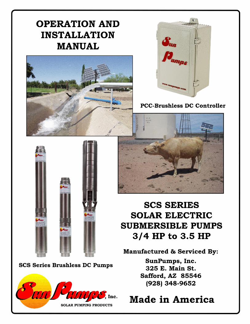
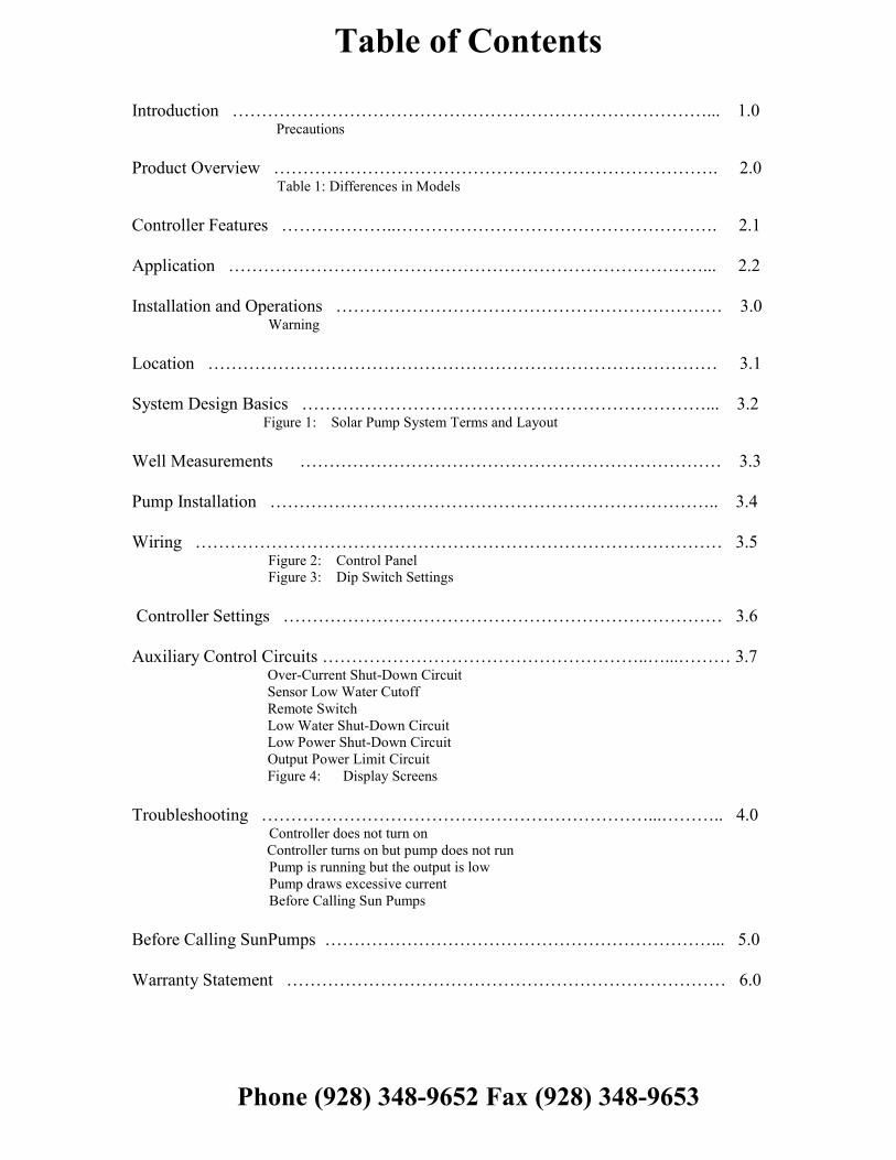
Table of Contents
Introduction ………………………………………………………………………... 1.0Precautions
Product Overview …………………………………………………………………. 2.0Table 1: Differences in Models
Controller Features ………………..………………………………………………. 2.1
Application ………………………………………………………………………... 2.2
Installation and Operations ………………………………………………………… 3.0Warning
Location …………………………………………………………………………… 3.1
System Design Basics ……………………………………………………………... 3.2Figure 1: Solar Pump System Terms and Layout
Well Measurements ……………………………………………………………… 3.3
Pump Installation ………………………………………………………………….. 3.4
Wiring ……………………………………………………………………………… 3.5Figure 2: Control PanelFigure 3: Dip Switch Settings
Controller Settings ………………………………………………………………… 3.6
Auxiliary Control Circuits ………………………………………………..…...……… 3.7Over-Current Shut-Down CircuitSensor Low Water CutoffRemote SwitchLow Water Shut-Down CircuitLow Power Shut-Down CircuitOutput Power Limit CircuitFigure 4: Display Screens
Troubleshooting …………………………………………………………...……….. 4.0Controller does not turn onController turns on but pump does not runPump is running but the output is lowPump draws excessive currentBefore Calling Sun Pumps
Before Calling SunPumps …………………………………………………………... 5.0
Warranty Statement ………………………………………………………………… 6.0
Phone (928) 348-9652 Fax (928) 348-9653
1.0 Introduction
Thank you for selecting a SunPumps SCS series solar pump system. The SCS series pump and PCC seriesSensorless Brushless DC - pump controller are the key components to high quality solar powered pumpingsystems. Their stand-alone, pollution free and low noise operation makes them an ideal solution for remotehomes, irrigation projects, and wildlife and stock watering without violating the environment.
SunPumps SCS series pumps are multi-stage centrifugal, DC powered, submersibles constructed of high qualitystainless steel. These pumps were designed specifically for water delivery in remote locations.
The PCC-BLS series controllers are microprocessor based solid state DC power converters designed as theinterface between a solar module array and a sensorless brushless DC pump motor. The purpose of the controlleris to operate the high efficiency, high reliability DC motor and maximize the total daily water output whileproviding protection for the pump as well as providing an interface with other related pumping system equipment.
Although these SCS series pump systems are easy to install, please read this manual to become familiarwith the controller features, functions, connection points and various configurations. For future reference,keep this manual and other relevant product information in a safe place.
PRECAUTIONS
Safety First – Always understand what you are doing when working with any form of electricity.Guessing may cause product damage and/or severe personal injury.
Shut down all power when working on the system.
Do not attempt to feed live wires into the PC-series controller. Product damage and/or personalinjury may result.
Do not exceed the voltage rating of the controller.
Do not set the controller to exceed the power rating of the motor. See 3.6 Controller Settings.
Do not splash water on the controller when the cover is open.
Mount the controller in a shaded, well vented, vertical position.
Installation of this system should be done by a licensed Pump Contractor.
2.0 Product Overview
The SunPumps PCC-BLS-M2 series controllers were designed specifically for SunPumps SCS-series, SensorlessBrushless DC submersible pumps. When properly installed and configured, the unique features incorporated intothis stand-alone system will automatically control and protect your pump system permitting many years ofdependable, trouble free service. SunPumps has produced multiple versions of this controller. The differencesbetween the two are certain set points and electrical characteristics which are detailed in the table below.
Table 1Controller Model Min
Voltage1Max
VoltageMin Power Max
PowerLow WaterCutoff Min
Low WaterCutoff Max
NominalVoltage
PCC-120BLS-M22 90 V 200 V Set by LWC 1500 W 100 W 585 W 120 VPCC-180BLS-M22 120 V 300 V Set by LWC 2250 W 100 W 1023 W 180 VPCC-240BLS-M22 220 V 380 V Set by LWC 3000 W 100 W 1023 W 240 V1Min Voltage is the minimum voltage which the unit must see in order to start the pump. If this voltage is not obtained, theunit will not attempt to start the pump. Voltages lower than this will not hurt the unit.2Both controller models have the same operating features, functionality and setup. Voltage and power tolerances are the onlydifferences of concern to the end user. This manual will only differentiate when necessary for clarity.
2.1 Controller Features
1. Current boosting for matching the load requirements of the pump.2. Voltage regulation of the solar electric array at its maximum power point. (MPPT)
3. Over-current protection via integrated electronic circuit breaker.
4. Reverse polarity protection (10 amperes maximum) on the input terminals.5. Voltage and current limiting to pump motor.
6. Transient protection and surge suppression.7. Adjustable output motor power control for precision output flow.
8. Digital display indicating status, power, voltage, current and more.
9. System ON/OFF switch.10. LED indicators; 1. Power In, 2. Motor Run, 3. MPPT, 4. RS Stop, 5. Low Power, 6. Over-Current, 7.
Fault Condition.
11. Weather resistant powder coated, die cast aluminum enclosure with a hinged door.12. Rising clamp screw terminal blocks – no fork terminals required.
13. Pre-adjusted pump configuration and power source selection.
14. Remote switch interface – float switch or remote shutdown –Normally Open or Normally Closed, userselectable.
15. Sensor and sensor less “Low Water Cutoff” circuit
16. Low Power Shut Down circuit
2.2 Application
The only application the PCC series controllers are designed for is the interface between a solar module array andSunPumps Sensorless Brushless DC motors.
No other applications or DC power sources are recommended or warrantied unless written approvalis provided by the SunPumps factory.
3.0 Installation and Operation
The following sections are outlined in a step-by-step format to guide you through the installation andconfiguration of an SCS series pump and PCC series controller. The procedure for installing the SCS submersiblepump is the same as a standard AC submersible pump. Any licensed pump contractor will be familiar with theproper installation procedures. The installation and operation should be in accordance with local regulations,accepted codes of good practice and common sense. This pump should be installed by a licensed professionalpump installer.
Before installing any pump system read all product manuals then review all system components to becomefamiliar with the physical and electrical layout. Check all equipment for any product damage. Refer toapplicable figure(s) as a guide during the installation. Controller door must be closed during normal operation.
Warning
Reverse polarity on a panel system capable of producing over 10 amps will result in non-warrantied product damage. Please check polarity before connecting power to the controller.
This controller is for SunPumps Sensorless Brushless DC Motors only. Do not use thiscontroller on Brush-Type motors or Sensor Type Brushless DC motors. Damage to thecontroller will result.
3.1 Location
As the majority of system installations vary greatly, only general comments can be made about the installationlocation. Prior to installing the system, it is suggested to make a system layout plan. During the system layout,take into consideration any potential shading of the solar electric modules, wire runs, wire size, conduit runs,trenching, controller accessibility, tank location, pump head etc. Shading even a small portion of the array canreduce the output of the entire array and thus reduce or completely stop the output of the pump. There is nosubstitute for a good plan!
The PCC-series controller can either be mounted indoors or outdoors. Locate all system equipment as close aspossible to each other. For top of pole mount racks, the controller is usually mounted on the north side (shadedside) of the mounting pole. The controller must be mounted in a vertical position for proper cooling and to keepthe electronics dry. The pole should be located close to the well (bore hole). This general physical layout isconducive to clean installation both aesthetically and electrically.
3.2 System Design Basics (Read carefully before installation)
1. The pump discharge piping should be sized for efficient pump operation. We suggest using the FrictionLoss Tables to calculate the Total Dynamic Head using different pipe sizes. As a rule of thumb use 1”for up to 8 GPM, 1 ¼” for up to 25 GPM, 1 ½” for up to 40 GPM and 2” for up to 70 GPM.
2. For optimum pump performance make sure that the wire is sized properly for the length of runbetween the pump and the solar modules. Wire sized too small will cause a decreased output from thepump. Keep the distance from the solar modules to the pump as short as possible. Refer to a DC wireloss chart for proper sizing. It is recommended to keep the voltage drop under 3%.
3. Due to the aggressive action of DC power, it is essential that any under-water splice be made correctly.This splice must be watertight. Improper sealing of the splice will cause poor pump performance andmay cause damage to the system. A submersible 4 wire splice kit is recommended for this watertightconnection.
4. Never rest the pump on the bottom of the well (bore hole). This can cause the pump to fill with mudand damage the impellers. It is recommended that the pump be set at least 10 feet off of the bottom of thebore hole. If this is not possible the pump may be placed a minimum of 5 feet above the bottom of thewell. If possible, install the pump above the well casing perforations. This will allow any sand intrusionto settle below the pump.
5. Never install a pump in a well that has had an oil-lubricated line shaft turbine in it without cleaning itfirst. Any drip oil remaining in the water may damage the pump shaft bearing sleeves.
6. On deep wells, a check valve should be installed in the drop pipe every 200 feet.
7. Never install the controller in direct sunlight. Direct sunlight on the controller may cause over-heatingof the controller.
8. Never lay the controller on the ground or mount the controller in a horizontal position. The controllershould be mounted in a vertical position only. A convenient place to mount the controller is on thenorth side (shaded side) of the solar module array.
9. The controller should be grounded to the pump motor housing, the frame of the solar modules and toan 8-foot ground rod. If the well casing is steel it may be used as the ground rod. Drill and tap a hole inthe casing or weld a bolt to the casing for the ground lug. Use only a copper lug to attach the groundwire. The cemented support structure pole will not provide an adequate ground. Do not ground thepositive or negative electrical wires. Always use a DC surge/lightning arrestor on the panel side of thecontroller. (Midnight Solar MN-SPD surge arrestor is recommended)
10. Do not ground the array positive or negative electrical wires.
3.3 Well Measurements
Before installing the pump measure the depth of the well (bore hole) and static water level. The static water levelis the distance from the top of the well casing to the water level in the well (bore hole). This information isnecessary in determining the pump setting (See Figure 1).

Figure 1 Solar Pump System Terms & Head Calculations
DrawDown
Static Water Level
VerticalLift
Pump Level
Pump Setting
SCS Submersible Pump
Pumping Level _____________Feet
Vertical Lift _____________Feet
Friction Loss _____________Feet
Total Dyn. Head _____________Feet
Total Dynamic Head = PL + VL + FL
Water Tank
Submersible Pump Cable
Sanitary Well Seal
Drop Pipe +
+
=
(See Friction Loss Chart)
Determining Total Dynamic Head
Pumping LevelPumping level is the vertical distance in feet from the discharge pipe at the well head to the water level in thewell while pumping at the specified flow rate.
Vertical LiftVertical lift is the vertical distance in feet from the discharge pipe at the well head to the discharge pipe at thetop of the water tank.
Friction LossFriction loss is the resistance to flow through a pipeline measured in PSI drop and converted to head feet. Theamount of loss depends on the diameter of the pipeline, the length of the pipeline, the flow rate, the numberand type of fittings and the coefficient of friction of the pipeline material. Refer to friction loss tables for yourspecific application. (There is a Friction Loss Program on the SunPumps web site in the engineering section atwww.sunpumps.com.)
3.4 Pump Installation
1. The well should be clean and disinfected before the pump is installed. You should always clean and develop anew well before installing the pump.
2. Write the pump, motor and controller model number and serial number in the space provided on the last page inthis Instruction Manual. This information will be needed when filling out the Warranty Card. And will aide inany troubleshooting which may be necessary.
3. Inspect all components for shipping damage and insure that you have all the components that are required for acomplete installation.
4. Select a well-ventilated, shaded location in which to vertically mount the control box. The shaded side of the solarpanel rack mounting pole is usually a convenient place.
5. If using unthreaded discharge pipe install a stainless steel or brass adapter fitting into the pump discharge head.Consult your pump supplier for other available adapter materials. Do not use galvanized connections onstainless steel or bronze discharge heads as galvanic corrosion will occur. Connect the drop pipe, safety ropeand sand shroud (if used) to the pump. Barbed type connectors should always be double clamped. For poly pipe,compression fittings are recommended.
6. Splice the drop cable to the motor lead using an under water splice kit. (See wire splicing instructions providedwith splice kit.) Match the drop cable wire colors to the pump motor leads. If the drop cable does not have thesame color wires as the pump, be sure to record which colors go to the various colors of the motor lead and labelthem. The motor can run in reverse if not connected properly.
7. You can now lower the pump into the well. Set the pump at least 10’ off the bottom (see 3.2 System DesignBasics #4). Never rest the pump on the bottom of the well. Never lower the pump by the submersible pumpcable.
8. Tie the drop pipe, drop cable and safety rope together every ten feet with 2” 10 mil pvc pipe wrap tape. Make surethat the tape does not loosen as it will block the pump suction if it falls down the well. The use of the safety ropeis at the discretion of the installer.
9. Slide the well seal over the discharge end of the pipe, connect the discharge fitting, pull the drop wire through thewell seal and connect the safety rope, if used, to the eye-bolt on the inside of the well seal.
10. Finish lowering the pump and pipe assembly into the well (bore hole) positioning the well seal over the top of thecasing. Connect the discharge pipe to the fitting on top of the well seal and run the pump wires to the controller.
3.5 Wiring
Prior to connecting any wires to the controller, be sure you have a system wiring diagram to use as a reference (seefigure 2). Guessing at polarity and connection points is not worth the risk of potential product damage and/or personalinjury.
Ensure the wire sizes are of adequate diameter (gauge) to minimize voltage drop. Please refer to a DC voltage losstable or call your SunPumps dealer for assistance. Wire gauge being too small will cause excessive voltage losses tothe motor and will reduce the flow rate of the pump.
All other system equipment should be installed before proceeding with wiring the controller. Double check polarityand wire termination tightness before powering up the system.
CAUTION: Photovoltaic panels produce DC electricity when exposed to sunlight. Cover the panels with ablanket or with a non-opaque material before wiring. Install a disconnect switch between the solar modulesand the controller.
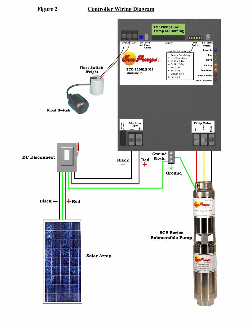
Figure 2 Controller Wiring Diagram
1. After mounting the controller, switch the controller to the OFF position.
2. Verify all dip switches are off at this time.
3. Connect ground rod conductor to the controller chassis ground block.
4. Connect solar module frame ground conductor to controller chassis ground block.
5. Connect the green pump ground conductor to controller chassis ground block.
6. Connect pump motor leads to the corresponding “Pump Motor” terminals on the controller. Red to “Red”, yellowto “Yellow” and black to “Black”.
7. Verify that the disconnect switch is in the off position. Connect the DC source supply negative (-), the blackconductor, to one of the controller terminals labeled “Negative” on the “Solar Array Input”. (NOTE: The powershould be connected to a disconnect and it should be in the OFF position before connecting power to thecontroller).
8. Connect the DC source supply positive (+), the red conductor, to one of the controller terminals labeled “Positive”on the “Solar Array Input”. (NOTE: The power should be connected to a disconnect and it should be in the OFFposition before connecting power to the controller).
9. Refer to the next section for “Remote Switch” and “Low Water Cutoff” connections as well as “AdjustmentProcedures” for configuration, if applicable.
10. At this point, all system components are installed and wired, double check conductor polarities, wire terminationtightness and controller configuration. With a DC volt meter check the array open circuit voltage (Voc) on thearray side of the disconnect switch and the module polarity. Record the Voc for future reference. You may dothis on the Before Calling Sun Pumps Worksheet near the end of this manual. Check this voltage reading againstthe “Voc” range for your specific system in the chart below. (Figure 3)
11. After you have verified the voltage and polarity, switch the disconnect switch on - if the polarity is correct the firstLED light will be on.
12. Turn the “On/Off “switch to the ON position. The system should be operational. If the system does not startand turns on any error lights or gives you an error message, proceed to the troubleshooting guide.
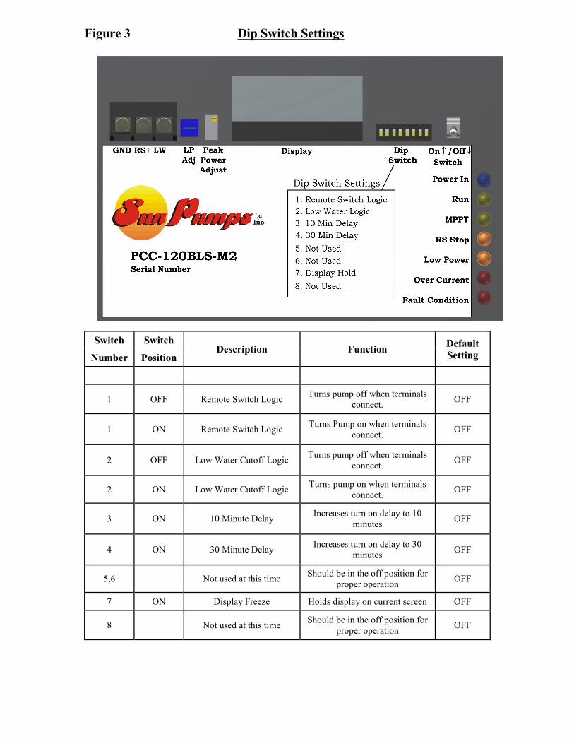
Figure 3 Dip Switch Settings
Switch SwitchDescription Function
DefaultSettingNumber Position
1 OFF Remote Switch LogicTurns pump off when terminals
connect.OFF
1 ON Remote Switch LogicTurns Pump on when terminals
connect.OFF
2 OFF Low Water Cutoff LogicTurns pump off when terminals
connect.OFF
2 ON Low Water Cutoff LogicTurns pump on when terminals
connect.OFF
3 ON 10 Minute DelayIncreases turn on delay to 10
minutesOFF
4 ON 30 Minute DelayIncreases turn on delay to 30
minutesOFF
5,6 Not used at this timeShould be in the off position for
proper operationOFF
7 ON Display Freeze Holds display on current screen OFF
8 Not used at this timeShould be in the off position for
proper operationOFF
3.6 Controller Settings
The PCC series controllers have several settings (see figure 3). Most features include system configurationadjustments, some of which are user selectable by an eight position DIP-switch located on the face of thecontroller.
Switch 1 is the Remote Switch Logic. With this switch off (down), terminals “RS+” and “GND” must beconnected to turn the controller off. With this switch on (up), terminals “RS+” and “GND” must be connected toturn the controller on.
Switch 2 is the Low Water Cutoff Logic. With this switch off (down), terminals “RS+” and “GND” must beconnected to turn the controller off. With this switch on (up), terminals “RS+” and “GND” must be connected toturn the controller on.
Switches 3 and 4 are delay timer adjustments. The delay timer is used for the remote switch and the low watercutoff. This timer by default is set for one minute. Switch 3 will increase the timer to 10 minutes; Switch 4 willincrease it to 30 minutes. See Remote Switch and Low Water Cutoff for more information.
Switch 7 is used to control the user interface. When switch 7 is down, the LCD will display various screensconveying pump and controller operating parameters. The display will cycle through each screen at apredetermined rate. For troubleshooting and some setup features certain screens are desired. By turning theswitch number 7 on, the display will stop cycling and the current screen will stay on the display.
Switches 5, 6, and 8 are not used at this time and should remain down.
3.7 Auxiliary Control Circuits
The auxiliary control circuits are configured and controlled with the “Dip Switches”, “LP Adj.”, “Speed Control”and the “RS”, “LW” and “GND” terminals. (See Figure 3)
These circuits offer expanded capability and are described here. The remote switch control is for float switches(storage tank level), pressure switches or a remote system “ON/OFF” toggle switch. The motor speed control isfor adjusting the flow rate of the pump. There is also the low water cutoff, low power shut down and over currentprotection circuits. See each corresponding detailed description below.
NOTE: Use only “Shielded Wire” to run from the remote switch to the controller and the ground wiremust be grounded to the controller side only. Induced voltages from lightning storms or two-way radiotransmissions could damage the controller.
Over-Current Shut Down Circuit
The over-current shut down circuit will turn the controller off any time the current exceeds the current limit of thecontroller. When it turns the controller off it will remain off for 3 minutes and then turn on again. When it turnsoff an error light will light and the display will say Over-Current. When it turns on again, if it is still pullingexcessive current it will continue to shut down for 3 minutes and try to restart.
Sensor Low Water Cutoff Circuit
The sensor type low water cutoff circuit is designed as a safety feature to protect your pump from running dry oryour tank from over flowing. The “LW” terminal of the controller should be attached to a low water sensorelectrode which is mounted in your tank or well. The system can be used to detect low water or to detect highwater depending on the position of switch 2 on the dip switch. When dip switch 2 is in the off position, the lowwater cutoff circuit expects not to touch water. If water comes into contact with it, and completes the circuit toground, the pump will shut off until the water is removed and the delay timer times out. A three minute timeout isdefault for this feature but is modifiable by switches 3 and 4 to 10 or 30 minutes respectively. This timeoutapplies to remote switch and low water cutoff.
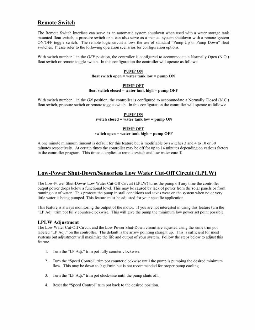
Remote Switch
The Remote Switch interface can serve as an automatic system shutdown when used with a water storage tankmounted float switch, a pressure switch or it can also serve as a manual system shutdown with a remote systemON/OFF toggle switch. The remote logic circuit allows the use of standard “Pump-Up or Pump Down” floatswitches. Please refer to the following operation scenarios for configuration options.
With switch number 1 in the OFF position, the controller is configured to accommodate a Normally Open (N.O.)float switch or remote toggle switch. In this configuration the controller will operate as follows:
PUMP ONfloat switch open = water tank low = pump ON
PUMP OFFfloat switch closed = water tank high = pump OFF
With switch number 1 in the ON position, the controller is configured to accommodate a Normally Closed (N.C.)float switch, pressure switch or remote toggle switch. In this configuration the controller will operate as follows:
PUMP ONswitch closed = water tank low = pump ON
PUMP OFFswitch open = water tank high = pump OFF
A one minute minimum timeout is default for this feature but is modifiable by switches 3 and 4 to 10 or 30minutes respectively. At certain times the controller may be off for up to 14 minutes depending on various factorsin the controller program. This timeout applies to remote switch and low water cutoff.
Low-Power Shut-Down/Sensorless Low Water Cut-Off Circuit (LPLW)
The Low-Power Shut-Down/ Low Water Cut-Off Circuit (LPLW) turns the pump off any time the controlleroutput power drops below a functional level. This may be caused by lack of power from the solar panels or fromrunning out of water. This protects the pump in stall conditions and saves wear on the system when no or verylittle water is being pumped. This feature must be adjusted for your specific application.
This feature is always monitoring the output of the motor. If you are not interested in using this feature turn the“LP Adj” trim pot fully counter-clockwise. This will give the pump the minimum low power set point possible.
LPLW AdjustmentThe Low Water Cut-Off Circuit and the Low Power Shut-Down circuit are adjusted using the same trim potlabeled “LP Adj.” on the controller. The default is the arrow pointing straight up. This is sufficient for mostsystems but adjustment will maximize the life and output of your system. Follow the steps below to adjust thisfeature.
1. Turn the “LP Adj.” trim pot fully counter clockwise.
2. Turn the “Speed Control” trim pot counter clockwise until the pump is pumping the desired minimumflow. This may be down to 0 gal/min but is not recommended for proper pump cooling.
3. Turn the “LP Adj.” trim pot clockwise until the pump shuts off.
4. Reset the “Speed Control” trim pot back to the desired position.
Output Power Limit Circuit (Motor Speed Control)
The Output Power Limit Control circuit is used to control the speed of the pump motor and thus the flow rate ofthe pump. It is primarily used for low producing wells where the pump output is matched to the production rate ofthe well. However it can also be used any time specific flow rates are required.
Output Power Limit AdjustmentThe purpose of this procedure is to adjust the output power of the controller and thus reduce the water flow of thepump. If tests have shown the pump will out produce the well capacity, then the controller “Speed Control”feature can be used to match the flow rate of the pump to the production of the well.
1. With the system installed and controller properly configured, allow the pump to run at full power at mid-dayuntil the pump starts surging.
2. Slowly turn the “Speed Control” trim pot located on the face of the controller counter clockwise until thepump stops surging. This is the point where the pump flow rate equals the well production. This process willprobably take a few attempts to “balance” the system for optimum water production. If maximum water is nota critical issue you may want to reduce the pumps flow rate an additional 5% to 10% to insure the pump willnot run dry.
(NOTE: The trim pot has a15- turn range. It usually takes many complete turns in a counter-clockwisedirection before you will notice any change in water output or output power on the display).
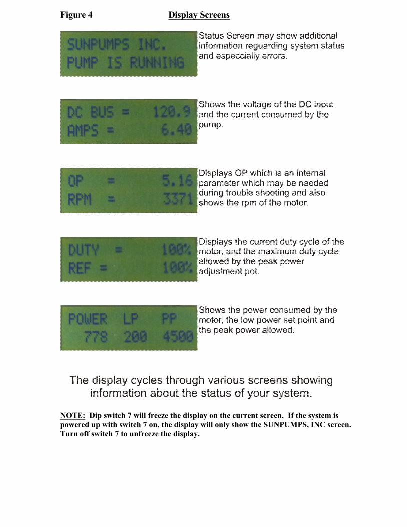
Figure 4 Display Screens
NOTE: Dip switch 7 will freeze the display on the current screen. If the system ispowered up with switch 7 on, the display will only show the SUNPUMPS, INC screen.Turn off switch 7 to unfreeze the display.
4.0 Troubleshooting
Sun Pumps, Inc. is dedicated to its customers and will gladly help you trouble shoot any problems with yoursystem. However, especially during the busy summer pumping season, we may not be able to help you rightaway. Using this trouble shooting guide as your first resource when your system is not working properly can saveyou valuable time in getting your system fully functional. If at any time however, you are not comfortableperforming any of these tasks, or do not fully understand the system, it is better to call than to guess. Beforecalling please go through the section below labeled “Before Calling Sun Pumps” and complete the stepsthere.
CONTROLLER DOES NOT TURN ON
1. Check the LED’s on the face of the controller. The top LED, labeled “Power In”, should be on. This indicatespower is connected to the controller and the polarity is correct. If it is not on, verify that the controller isproperly wired, including polarity, and that the input terminals have at least 60 volts. Less than 60 volts at theinput terminals and the unit may show no signs of operation. If you do have at least 60 volts in the rightpolarity, contact Sun Pumps for further assistance.
2. If the expected voltage is not present, disconnect the panels from the controller using the disconnect, andcheck any fuses and breakers in the system. Replace blown fuses and reset tripped breakers.
3. If there are not blown fuses and no tripped breakers, check the open circuit voltage of your array. If the opencircuit voltage is not correct trouble shoot the array to find the problem. If the open circuit voltage is correct,call Sun Pumps for further assistance.
CONTROLLER TURNS ON BUT PUMP DOES NOT RUN
1. Make sure the On/Off switch is in the up position. (On)
2. The second LED is labeled “Run”. This indicates the pump is running. If it is on, go to the bore hole andlisten for the sound of the motor. Check for breaks in the pipe. If you cannot find a problem call Sun Pumpsfor further assistance.
3. Check the fourth LED, labeled “RS Stop”; this is the remote switch shutdown indicator. If it is on, the remotecircuit or low water cutoff circuit is preventing the controller from running the pump. Set the #1 and #2 dipswitches to off and disconnect the remote switch and low water cutoff. If the pump starts, troubleshoot theremote switch and low water cutoff individually. If the pump does not start and the LED is still lit, call SunPumps for further assistance.
4. Check the fifth LED, labeled “Low Power”; this is the low power shutdown indicator. If it is on, thecontroller detected a low power or low water condition. The low power shut down is a common occurrenceon days which have clouds which block the sun momentarily. First check the input voltage to the controller.This will be shown on the LCD screen called DC BUS. Verify that this exceeds the minimum voltage inTable 1. If it does not meet or exceed the minimum voltage, you do not have enough power to start your
pump. Note: To accurately trouble shoot this feature there should be absolutely no clouds blocking the sunat any time during the following tests. If you have enough input voltage, turn the controller off then on againto reset this fault. If the low power or low water condition still exists then the controller will start but shutdown again. Verify power using the LCD screen. Wait for the screen to cycle to the power reading and turnon dip switch # 7. Note the number underneath the “LP” on the display. Cycle the pump off then on andwatch the power reading. If the power reading goes higher than the LP set point, the controller is shuttingdown due to a low water condition. If the number is not higher than the set point, skip to step 7. Check toverify the pump is not running out of water. If your pump is not running out of water, call Sun Pumps forfurther assistance.
5. If the sixth LED, labeled “Over Current” is on, the controller has exceeded its current limit and shut down.Turning the controller off then on again will reset this fault. If the controller continues to need high current, itwill turn itself off again. Check the pump for a short to ground using an ohm meter and call Sun Pumps forfurther assistance.
6. If the seventh LED, labeled “Fault Condition”, is on, this indicates a motor or ground fault fuse error. Checkthe controller display for the type of fault. Check motor wiring and connections. If the screen displays “GF
FUSE OPEN” the ground fault fuse has been blown. Check your system for ground loops and replace thefuse with a 500 VDC 1A rated fuse. If this does not solve the issue, contact Sun Pumps for further assistance.
7. Check for proper dip switch settings on your controller. Switches 5, 6, and 8 must be in the off position forproper operation.
8. Check for proper controller input voltage. A quick look at the controller display will verify the array voltage.If the pump is not running the display should be reading the array open circuit voltage, (Voc). Verify that thisvoltage is below the maximum input voltage allowed for your controller (Model Dependent See Table 1).Check the Voc on the label on the back of the solar modules and multiply this figure times the number ofmodules that are connected in series. This number should be + - 10% of the display reading. If it is not thenconfirm all electrical terminations are tight and secure. Use a DC volt meter to check each solar module forproper open circuit voltage (Voc). One bad module will drop the voltage on the complete series string.
PUMP IS RUNNING BUT THE OUTPUT IS LOW
1. Make sure you have full sun light at midday, that there are no clouds and no shadows on any part of the array.Then verify power coming out of the controller. Look at the LCD screen and read the voltage, current andpower. Check this against the pump chart for your specific application.
2. If the power is correct for your pump model and array size then make sure the pump wires are connected tothe proper terminals. If two wires are reversed the motor will be running in reverse. It may still pump but notat the full rated output.
3. If the wires are correct verify that your system does not have any leaks where water can be lost. If you cannotdetermine the problem, contact Sun Pumps for further assistance.
PUMP DRAWS EXCESSIVE CURRENT (More than the rating of the pump, but less than the rating ofthe controller)
1. Check wiring diagram for proper connection.
2. Check for skinned wires or faulty underwater splice.
3. Check for locked motor armature. With the pump out of the well, remove the pump end from the motor (ifthis is not feasible skip this step and contact Sun Pumps). Allow the controller to attempt to start the motor.If the motor still does not run. Contact the Sun Pumps for further assistance.
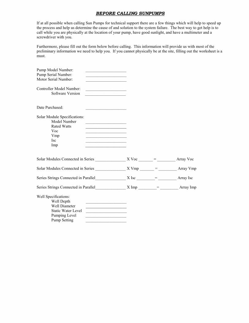
BEFORE CALLING SUNPUMPS
If at all possible when calling Sun Pumps for technical support there are a few things which will help to speed upthe process and help us determine the cause of and solution to the system failure. The best way to get help is tocall while you are physically at the location of your pump, have good sunlight, and have a multimeter and ascrewdriver with you.
Furthermore, please fill out the form below before calling. This information will provide us with most of thepreliminary information we need to help you. If you cannot physically be at the site, filling out the worksheet is amust.
Pump Model Number: ____________________Pump Serial Number: ____________________Motor Serial Number: ____________________
Controller Model Number: ____________________Software Version ____________________
Date Purchased: ____________________
Solar Module Specifications:Model Number ____________________Rated Watts ____________________Voc ____________________Vmp ____________________Isc ____________________Imp ____________________
Solar Modules Connected in Series _______________ X Voc _______ = _________ Array Voc
Solar Modules Connected in Series _______________ X Vmp _______ = _________ Array Vmp
Series Strings Connected in Parallel_______________ X Isc _________= _________ Array Isc
Series Strings Connected in Parallel_______________ X Imp _________= _________ Array Imp
Well Specifications:Well Depth ____________________Well Diameter ____________________Static Water Level ____________________Pumping Level ____________________Pump Setting ____________________
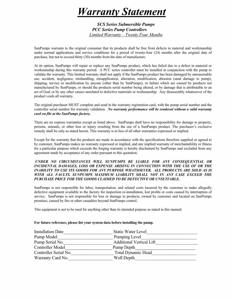
Warranty StatementSCS Series Submersible Pumps
PCC Series Pump ControllersLimited Warranty – Twenty Four Months
SunPumps warrants to the original consumer that its products shall be free from defects in material and workmanshipunder normal applications and service conditions for a period of twenty-four (24) months after the original date ofpurchase, but not to exceed thirty (30) months from the date of manufacture.
At its option, SunPumps will repair or replace any SunPumps product, which has failed due to a defect in material orworkmanship during this warranty period. A PCC series controller must be installed in conjunction with the pump tovalidate the warranty. This limited warranty shall not apply if the SunPumps product has been damaged by unreasonableuse, accident, negligence, mishandling, misapplication, alteration, modification, abrasion (sand damage to pump),shipping, service or modification by anyone (other than by SunPumps), or failure which are caused by products notmanufactured by SunPumps, or should the products serial number being altered, or by damage that is attributable to anact of God, or by any other causes unrelated to defective materials or workmanship. Any disassembly whatsoever of theproduct voids all warranty.
The original purchaser MUST complete and send in the warranty registration card, with the pump serial number and thecontroller serial number for warranty validation. No warranty performance will be rendered without a valid warrantycard on file at the SunPumps factory.
There are no express warranties except as listed above. SunPumps shall have no responsibility for damage to property,persons, animals, or other loss or injury resulting from the use of a SunPumps product. The purchaser’s exclusiveremedy shall be only as stated herein. This warranty is in lieu of all other warranties expressed or implied.
Except for the warranty that the products are made in accordance with the specifications therefore supplied or agreed toby customer, SunPumps makes no warranty expressed or implied, and any implied warranty of merchantability or fitnessfor a particular purpose which exceeds the forging warranty is hereby disclaimed by SunPumps and excluded from anyagreement made by acceptance of any order pursuant to this quotation.
UNDER NO CIRCUMSTANCES WILL SUNPUMPS BE LIABLE FOR ANY CONSEQUENTIAL ORINCIDENTAL DAMAGES, LOSS OR EXPENSE ARISING IN CONNECTION WITH THE USE OF OR THEINABILITY TO USE ITS GOODS FOR ANY PURPOSE WHATSOEVER. ALL PRODUCTS ARE SOLD AS ISWITH ALL FAULTS. SUNPUMPS MAXIMUM LIABILITY SHALL NOT IN ANY CASE EXCEED THEPURCHASE PRICE FOR THE GOODS CLAIMED TO BE DEFECTIVE OR UNSUITABLE.
SunPumps is not responsible for labor, transportation, and related costs incurred by the customer to make allegedlydefective equipment available to the factory for inspection re-installation, lost profits or costs caused by interruption ofservice. SunPumps is not responsible for loss or damage to products, owned by customer and located on SunPumpspremises, caused by fire or other casualties beyond SunPumps control.
This equipment is not to be used for anything other than its intended purpose as stated in this manual.
For future reference, please list your system data before installing the pump.
Installation Date______________________ Static Water Level_______________________Pump Model_________________________ Pumping Level_________________________Pump Serial No.______________________ Additional Vertical Lift___________________Controller Model_____________________ Pump Depth___________________________Controller Serial No.___________________ Total Dynamic Head____________________Warranty Card No.____________________ Well Depth___________________________