Embed Size (px)
DESCRIPTION
Rheem Tankless Water Heater Installation
Citation preview
94% CONDENSING TANKLESS WATER HEATER
AP15896-1(11/10) Printed in USA
*All models available for natural gas (N) or propane gas (P) usage.
Do not destroy manual. Please read carefully and keep in a safe place for future reference.
CERTIFIED
R
Direct Vent ModelsRheem/EcoSenseRTGH-95DV*RTGH-84V*ECOH200DV*ECOH160DV*Paloma/Wai WelaPHH-32RDV*PHH-25RDV*
Ruud RUTGH-95DV*RUTGH-84DV*RichmondRMTGH95DV*RMTGH84DV*
Outdoor ModelsRheem/EcoSenseRTGH-95X*RTGH-84X*ECOH200X*ECOH160X*Paloma/Wai WelaPHH-32ROF*PHH-25ROF*Ruud RUTGH-95X*RUTGH-84X*RichmondRMTGH95X*RMTGH84X*
WARNING: If the information in these instructions is not followed exactly, a fire or explosion may result, causing death, personal injury, or property damage.
For Your Safety!• Do not store or use gasoline
or other flammable vapors and liquids in the vicinity of this or any other appliance. To do so may result in an explosion or fire.
• Installation and service must be performed by a qualified installer, service agency, or the gas supplier.
What to Do If You Smell Gas• Do not try to light any
appliance.• Do not touch any electrical
switch; do not use any phone in your building.
• Immediately call your gas supplier from a neighbor’s phone. Follow the gas supplier’s instructions.
• If you cannot reach your gas supplier, call the fire department.
• Do not return to your home until authorized by the gas supplier or fire department.
DESIGN
CERTIFIED ®
USE AND CARE MANUALWith Installation Instructions for the Installer
Water Heaters for Other Than Recreational Vehicle Installation Only
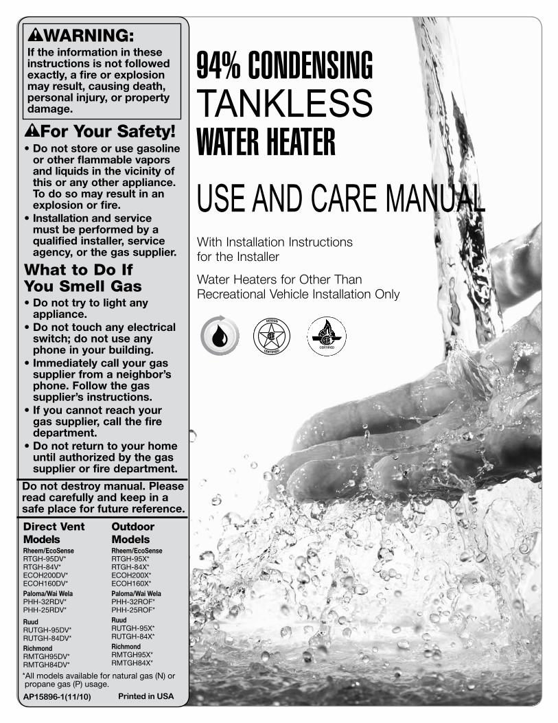
Important Safety InformationSafety Precautions .................................................. 2–8
Product InformationProduct Information .................................................... 8Specifications ........................................................ 9, 10General Descriptions ............................................11, 12
Using Your Water HeaterSetting the Water Temperature ............................ 13, 14
Caring for Your Water HeaterWater Heater Inspections .................................... 15, 16Care and Cleaning ................................................17, 18Preventive Maintenance ............................................ 19Draining the Water Heater .....................................20–22Freeze Protection ...................................................... 22Vacation and Extended Shutdown ........................... 23Troubleshooting Chart ......................................... 23, 24Service Error Code Chart .................................... 25, 26
Safet
y
If You Need ServiceCall for Assistance .................................................... 26
Installation InstructionsStandards Compliance ...............................................28Choosing a Location ............................................ 28, 29Product Inspection .................................................... 30Water Heater Installation ...................................... 30–33Venting .................................................................. 34–46Water Supply ........................................................ 47–51Condensate ................................................................51Gas Supply ........................................................... 52–56Electrical Wiring .................................................... 56–60Remote Control Installation .................................. 59, 60Insulation Blankets .....................................................61Installation Checklist ..................................................62Lighting the Water Heater ....................................63, 64Setting the Water Temperature .............................65–68High-Altitude Adjustments ...................................67, 68
Parts Replacement ...........................................69, 70
2
CONTENTS
READ THE SAFETY INFORMATIONYour safety and the safety of others are very important. There are many important safety messages in this manual and on your appliance. Always read and obey all safety messages.
This is the safety alert symbol. Recognize this symbol as an indication of Important Safety Information! This symbol alerts you to potential hazards
that can kill or hurt you and others.
All safety messages will follow the safety alert symbol and either the word “DANGER,” “WARNING,” “CAUTION,” or “NOTICE.”
2
These words mean:
IMPORTANT SAFETY INFORMATION
• This water heater is not suitable for use in manufactured (mobile) homes!
• Improper installation, adjustment, alteration, service, or maintenance can cause death, personal injury, or property damage. Refer to this manual.
READ ALL INSTRUCTIONS BEFORE USING.Be sure to read and understand the entire Use and Care Manual before attempting to install or operate this water heater. It may save you time and money. Pay particular attention to the Safety Instructions. Failure to follow these warnings could result in death or serious bodily injury. Should you have problems understanding the instructions in this manual, or have any questions, STOP and get help from a qualified service technician or the local gas utility.
WARNING: California Proposition 65This product contains chemicals known to the state of California to cause cancer, birth defects, or other reproductive harm.
WARNINGS:
DANGER: An imminently hazardous situation that will result in death or serious injury.
NOTICE: Attention is called to observe a specified procedure or maintain a specific condition.
CAUTION: A potentially hazardous situation that may result in minor or moderate injury.
WARNING: A potentially hazardous situation that can result in death or serious injury and/or damage to property.
Safety
3
IMPORTANT SAFETY INFORMATION
D A N G E R
FLAMMABLES Flammable Vapors
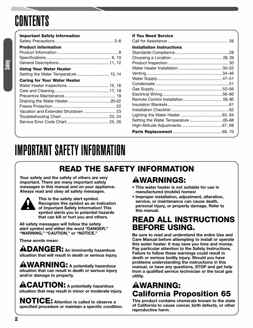
Water heater has a mainburner flame.The main burner flame:1. which can come on at any time and2. will ignite flammable vapors.Vapors:1. cannot be seen,2. are heavier than air,3. go a long way on the floor and4. can be carried from other rooms to the main burner flame by air currents.
Vapors from flammableliquids will explode andcatch fire causing death orsevere burns.Do not use or store flammableproducts such as gasoline,solvents or adhesives in thesame room or area near thewater heater.
Keep flammable products:1. far away from heater,2. in approved containers,3. tightly closed and4. out of children's reach.
Installation:Do not install water heaterwhere flammable products willbe stored or used unless themain burner flame is at least
18" above the floor. This will reduce, but not eliminate, the risk of vapors being ignited by the main burner flame.
Read and follow water heater warnings and instructions. If owners manual is missing, contact the retailer or manufacturer.
Water Heater Venting Safety
3
DANGER: Failure to install and properly vent the water heater to the outdoors as outlined in the “Venting” section of the Installation Instructions in this manual will result in death from fire, explosion, or asphyxiation from carbon monoxide. NEVER operate this water heater unless it is properly vented and has an adequate air supply for proper operation.
Be sure to inspect the vent terminal, the air intake, and the vent system on the water heater for proper installation at initial start-up and at least annually thereafter. Refer to the “Care and Cleaning” section of this manual for more information regarding vent system inspection.
WARNINGS: • Gasoline and other flammable liquids, materials,
and vapors (including paint thinners, solvents, and adhesives) are extremely dangerous. DO NOT handle, use, or store gasoline or other flammable or combustible materials anywhere in the vicinity of a water heater or any other appliance. Be sure to read and follow the labels on the water heater, as well as the warnings printed in this manual. Failure to do so can result in death, bodily injury, or property damage.
• Combustible construction refers to adjacent walls and ceilings and should not be confused with combustible or flammable products and materials. Combustible materials, such as clothing, cleaning materials, or flammable liquids, should never be stored in the vicinity of this or any gas appliance. Fire or explosion can occur causing death, personal injury, and/or product damage. See page 29 for clearances to combustible materials.
• Follow vent manufacturer’s instructions for venting installation, including additional clearances from combustibles, to avoid conditions that can lead to death, personal injury, and/or property damage.
• Use tankless water heater manufacturer-approved Schedule 40 PVC (foam core is not permitted at any time), Schedule 80 PVC, CPVC, ABS, or UL 1738-listed Category III Stainless Steel. No other vent material is permitted.
• Moisture in the flue gas will condense as it leaves the vent terminal. In cold weather this condensate can freeze on the exterior wall, under the eaves, and on surrounding objects. Some discoloration to the exterior of the building is to be expected. However, improper location or installation can result in severe damage to the structure or exterior finish of the building.
• For multiple-unit installation, a minimum distance between vent terminations must be maintained to prevent recirculation of vent gases. See page 39 for information on venting and clearances to multiple terminations.
CAUTIONS: • Ensure that the appliance vent is securely glued and
attached to the vent connection on the top of the water heater. DO NOT USE SCREWS.
• Do not operate without the condensate drain connected and routed to the proper drain.
4
IMPORTANT SAFETY INFORMATIONWater Supply Safety
DANGERS: • WATER TEMPERATURE
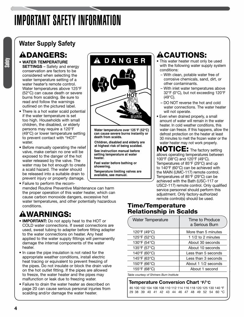
SETTINGS – Safety and energy conservation are factors to be considered when selecting the water temperature setting of a water heater’s remote control. Water temperatures above 125°F (52°C) can cause death or severe burns from scalding. Be sure to read and follow the warnings outlined on the pictured label.
• There is a hot water scald potential if the water temperature is set too high. Households with small children, the disabled, or elderly persons may require a 120°F (49°C) or lower temperature setting to prevent contact with “HOT” water.
• Before manually operating the relief valve, make certain no one will be exposed to the danger of the hot water released by the valve. The water may be hot enough to create a scald hazard. The water should be released into a suitable drain to prevent injury or property damage.
• Failure to perform the recom-
D A N G E R!
HOT
Water temperature over 125°F (52°C)can cause severe burns instantly or death from scalds.Children, disabled and elderly areat highest risk of being scalded.See instruction manual beforesetting temperature at waterheater.Feel water before bathing orshowering.Temperature limiting valves areavailable, see manual.
BURN
CAUTIONS: • This water heater must only be used
with the following water supply system conditions:– With clean, potable water free of
corrosive chemicals, sand, dirt, or other contaminants.
– With inlet water temperatures above 32°F (0°C), but not exceeding 120°F (49°C).
– DO NOT reverse the hot and cold water connections. The water heater will not operate.
• Even when drained properly, a small amount of water will remain in the water heater. In cold weather conditions, this water can freeze. If this happens, allow the defrost protection on the heater at least 30 minutes to melt the frozen water or the water heater may not work properly.
NOTICE: The factory setting allows operating temperatures between 100°F (38°C) and 120°F (49°C). Temperatures of 85°F (29°C) and up to 140°F (60°C) can be achieved with the MAIN (UMC-117) remote control. Temperatures of 85°F (29°C) can be achieved with the Bath (USC-117 or USC2-117) remote control. Only qualified service personnel should perform this adjustment. Only factory-authorized remote control(s) should be used.
• mended Routine Preventive Maintenance can harm the proper operation of this water heater, which can cause carbon monoxide dangers, excessive hot water temperatures, and other potentially hazardous conditions.
WARNINGS: • IMPORTANT: Do not apply heat to the HOT or
COLD water connections. If sweat connections are used, sweat tubing to adapter before fitting adapter to the water connections on heater. Any heat applied to the water supply fittings will permanently damage the internal components of the water heater.
• In case the pipe insulation is not rated for the appropriate weather conditions, install electric heat tracing or equivalent to prevent freezing of the pipes. Do not insulate or block the drain valve on the hot outlet fitting. If the pipes are allowed to freeze, the water heater and the pipes may malfunction or leak due to freezing water.
• Failure to drain the water heater as described on page 20 can cause serious personal injuries from scalding and/or damage the water heater.
Time/Temperature Relationship in Scalds
120°F (49°C) More than 5 minutes 125°F (52°C) 1 1/2 to 2 minutes 130°F (54°C) About 30 seconds 135°F (57°C) About 10 seconds 140°F (60°C) Less than 5 seconds 145°F (63°C) Less than 3 seconds 150°F (66°C) About 1 1/2 seconds 155°F (68°C) About 1 secondTable courtesy of Shriners Burn Institute
Water Temperature Time to Produce a Serious Burn
Temperature Conversion Chart °F/°C 85 100 102 104 106 108 110 112 114 116 118 120 125 130 140 °F 29 38 39 40 41 42 43 44 46 47 48 49 52 54 60 °C
Safet
y
5
IMPORTANT SAFETY INFORMATION
WARNINGS: • The installation of gas piping must conform to local
utility company requirements and/or in the absence of local codes, use the latest edition of National Fuel Gas Code (NFGC), ANSI Z223.1/NFPA 54, or CSA B149.1, Natural Gas and Propane Installation Code.
• Install a gas pressure regulator in the gas supply line. The regulator should not exceed the maximum supply pressure. DO NOT use an industrial-type gas regulator.
• Should overheating occur or the gas supply fail to shut off, turn off the manual gas control valve to the water heater.
CAUTIONS: • Do not attempt repair of electrical wiring, gas piping,
remote control, burners, vent connectors, or other safety devices. Refer repairs to qualified service personnel.
• Turn off the manual gas shut-off valve if the water heater has been subjected to overheating, fire, flood, physical damage, or if the gas supply fails to shut off.
• Do not turn on the water heater unless the water and gas supplies are completely opened.
Natural Gas and Liquefied Petroleum Safety
DANGERS: • Never attempt to convert the water heater from
natural gas to LP. The water heater should only use the fuel type in accordance with listing on data plate—natural gas for natural gas units and LP for LP units. Any other fuel usage will result in death or serious personal injury from fire and/or explosion. This water heater is not certified for any other fuel type.
• Both natural gas and propane (LP) have an odorant added to aid in detecting a gas leak. Some people may not physically be able to smell or recognize this odorant. If you are unsure or unfamiliar with the smell of natural gas or LP, ask the gas supplier. Other conditions, such as “odorant fade,” which causes the odorant to diminish in intensity, can also hide or camouflage a gas leak.
• Water heaters using LP gas are different from natural gas models. A natural gas water heater will not function safely on LP and vice versa.
• LP water heaters should not be installed below grade (for example, in a basement) if such installation is prohibited by federal, state, and/or local laws, rules, regulations, or customs.
• LP must be used with great caution. It is heavier than air and will collect first in lower areas, making it hard to detect at nose level.
• Before attempting to light the water heater, make sure to look and smell for gas leaks. Use a soapy solution to check all gas fittings and connections. Bubbling at a connection indicates a leak that must be corrected. When smelling to detect a gas leak, be sure to also sniff near the floor.
• Gas detectors are recommended in LP and natural gas applications and their installation should be in accordance with the detector manufacturer’s recommendations and/or local laws, rules, regulations, or customs.
• Combustible materials, such as clothing, cleaning materials, or flammable liquids, must not be placed in the vicinity of the water heater.
• If a gas leak is present or suspected:
– Do not attempt to find the cause yourself.– Never use an open flame to test for gas leaks. The
gas can ignite resulting in death, personal injury, or property damage.
– Follow the steps listed under “What to Do If You Smell Gas” found on the front cover of this manual.
Safety
6
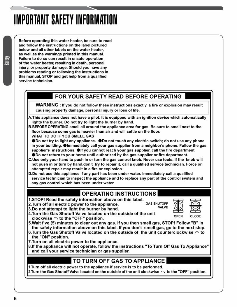
IMPORTANT SAFETY INFORMATIONBefore operating this water heater, be sure to read and follow the instructions on the label pictured below and all other labels on the water heater, as well as the warnings printed in this manual. Failure to do so can result in unsafe operation of the water heater, resulting in death, personal injury, or property damage. Should you have any problems reading or following the instructions in this manual, STOP and get help from a qualified service technician.
WARNING : If you do not follow these instructions exactly, a fire or explosion may resultcausing property damage, personal injury or loss of life.
FOR YOUR SAFETY READ BEFORE OPERATING
1.STOP! Read the safety information above on this label.2.Turn off all electric power to the appliance.3.Do not attempt to light the burner by hand.4.Turn the Gas Shutoff Valve located on the outside of the unit clockwise to the "OFF" position.5.Wait five (5) minutes to clear out any gas. If you then smell gas, STOP! Follow "B" in the safety information above on this label. If you don't smell gas, go to the next step.6.Turn the Gas Shutoff Valve located on the outside of the unit counterclockwise to the "ON" position.7.Turn on all electric power to the appliance.8.If the appliance will not operate, follow the instructions "To Turn Off Gas To Appliance" and call your service technician or gas supplier.
TO TURN OFF GAS TO APPLIANCE 1.Turn off all electric power to the appliance if service is to be performed.
2.Turn the Gas Shutoff Valve located on the outside of the unit clockwise to the "OFF" position.
GAS SHUTOFF VALVE
OPEN CLOSE
OPERATING INSTRUCTIONS
Safet
y
7
IMPORTANT SAFETY INFORMATIONElectrical Safety
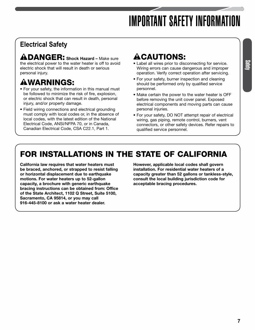
DANGER: Shock Hazard – Make sure the electrical power to the water heater is off to avoid electric shock that will result in death or serious personal injury.
WARNINGS:• For your safety, the information in this manual must
be followed to minimize the risk of fire, explosion, or electric shock that can result in death, personal injury, and/or property damage.
• Field wiring connections and electrical grounding must comply with local codes or, in the absence of local codes, with the latest edition of the National Electrical Code, ANSI/NFPA 70, or in Canada, Canadian Electrical Code, CSA C22.1, Part 1.
CAUTIONS: • Label all wires prior to disconnecting for service.
Wiring errors can cause dangerous and improper operation. Verify correct operation after servicing.
• For your safety, burner inspection and cleaning should be performed only by qualified service personnel.
• Make certain the power to the water heater is OFF before removing the unit cover panel. Exposed electrical components and moving parts can cause personal injuries.
• For your safety, DO NOT attempt repair of electrical wiring, gas piping, remote control, burners, vent connectors, or other safety devices. Refer repairs to qualified service personnel.
California law requires that water heaters must be braced, anchored, or strapped to resist falling or horizontal displacement due to earthquake motions. For water heaters up to 52-gallon capacity, a brochure with generic earthquake bracing instructions can be obtained from: Office of the State Architect, 1102 Q Street, Suite 5100, Sacramento, CA 95814, or you may call 916-445-8100 or ask a water heater dealer.
However, applicable local codes shall govern installation. For residential water heaters of a capacity greater than 52 gallons or tankless-style, consult the local building jurisdiction code for acceptable bracing procedures.
FOR INSTALLATIONS IN THE STATE OF CALIFORNIA
Safety
8
IMPORTANT SAFETY INFORMATION
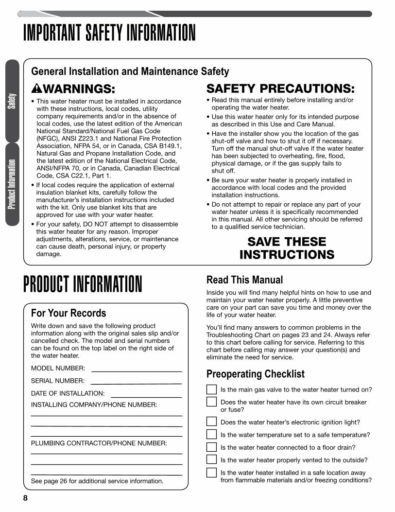
General Installation and Maintenance SafetyWARNINGS:
• This water heater must be installed in accordance with these instructions, local codes, utility company requirements and/or in the absence of local codes, use the latest edition of the American National Standard/National Fuel Gas Code (NFGC), ANSI Z223.1 and National Fire Protection Association, NFPA 54, or in Canada, CSA B149.1, Natural Gas and Propane Installation Code, and the latest edition of the National Electrical Code, ANSI/NFPA 70, or in Canada, Canadian Electrical Code, CSA C22.1, Part 1.
• If local codes require the application of external insulation blanket kits, carefully follow the manufacturer’s installation instructions included with the kit. Only use blanket kits that are approved for use with your water heater.
• For your safety, DO NOT attempt to disassemble this water heater for any reason. Improper adjustments, alterations, service, or maintenance can cause death, personal injury, or property damage.
SAVE THESE INSTRUCTIONS
SAFETY PRECAUTIONS: • Read this manual entirely before installing and/or
operating the water heater.• Use this water heater only for its intended purpose
as described in this Use and Care Manual.• Have the installer show you the location of the gas
shut-off valve and how to shut it off if necessary. Turn off the manual shut-off valve if the water heater has been subjected to overheating, fire, flood, physical damage, or if the gas supply fails to shut off.
• Be sure your water heater is properly installed in accordance with local codes and the provided installation instructions.
• Do not attempt to repair or replace any part of your water heater unless it is specifically recommended in this manual. All other servicing should be referred to a qualified service technician.
PRODUCT INFORMATIONFor Your RecordsWrite down and save the following product information along with the original sales slip and/or cancelled check. The model and serial numbers can be found on the top label on the right side of the water heater.
MODEL NUMBER:
SERIAL NUMBER:
DATE OF INSTALLATION:
INSTALLING COMPANY/PHONE NUMBER:
PLUMBING CONTRACTOR/PHONE NUMBER:
See page 26 for additional service information.
Read This ManualInside you will find many helpful hints on how to use and maintain your water heater properly. A little preventive care on your part can save you time and money over the life of your water heater.
You’ll find many answers to common problems in the Troubleshooting Chart on pages 23 and 24. Always refer to this chart before calling for service. Referring to this chart before calling may answer your question(s) and eliminate the need for service.
Preoperating ChecklistIs the main gas valve to the water heater turned on?
Does the water heater have its own circuit breaker or fuse?
Does the water heater’s electronic ignition light?
Is the water temperature set to a safe temperature?
Is the water heater connected to a floor drain?
Is the water heater properly vented to the outside?
Is the water heater installed in a safe location away from flammable materials and/or freezing conditions?
Produ
ct Inf
ormati
onSa
fety
9
PRODUCT INFORMATIONProduct Information
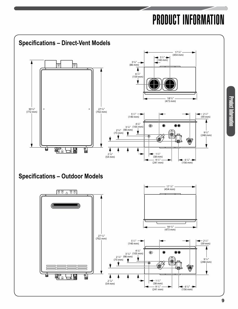
303/8"(772 mm)
275/8"(702 mm)
33/8"(86 mm)
51/2"(140 mm)
61/4"(159 mm)
177/8"(454 mm)
185/8"(473 mm)
93/4"(248 mm)
21/4"(59 mm)
51/2"(140 mm)
61/8"(156 mm)
21/8"(54 mm)
37/8"(98 mm)27/8"
(73 mm)
41/8"(105 mm)
91/2"(241 mm)
11/2"(38 mm)
Specifications – Direct-Vent Models
17 7/8"(454 mm)
18 5/8"(473 mm)
27 5/8"(702 mm)
9 3/4"(248 mm)
21/4"(59 mm)
51/2"(140 mm)
61/8"(156 mm)
2 1/8"(54 mm)
3 7/8"(98 mm)2 7/8"
(73 mm)
41/8"(105 mm)
9 1/2"(241 mm)
11/2"(38 mm)
Specifications – Outdoor Models
10
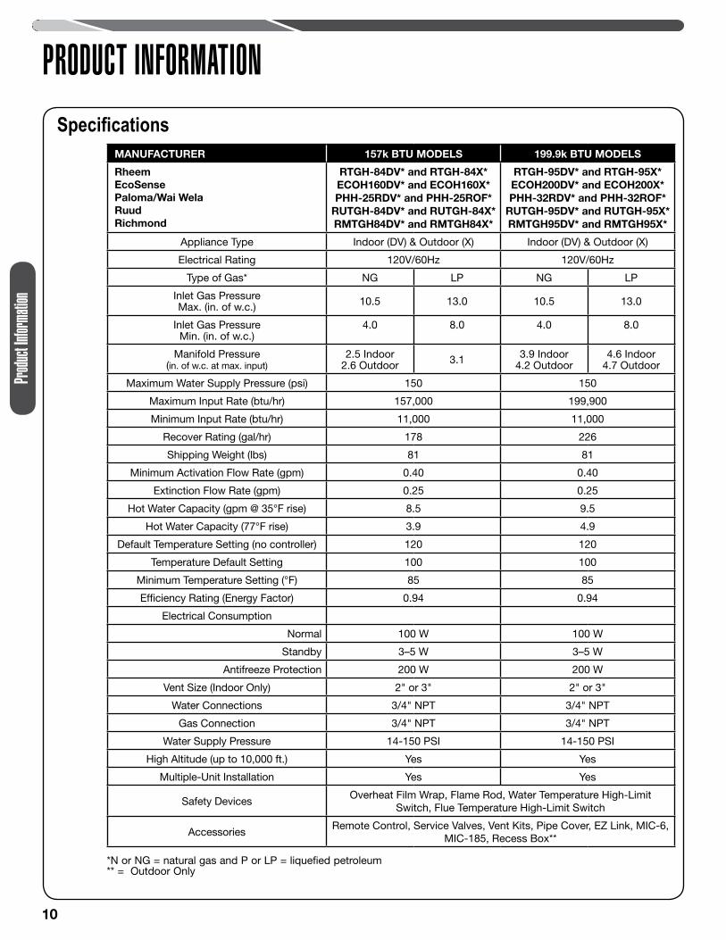
PRODUCT INFORMATIONSpecifications
MANUFACTURER 157k BTU MODELS 199.9k BTU MODELS
RheemEcoSense Paloma/Wai WelaRuudRichmond
RTGH-84DV* and RTGH-84X* ECOH160DV* and ECOH160X* PHH-25RDV* and PHH-25ROF*
RUTGH-84DV* and RUTGH-84X* RMTGH84DV* and RMTGH84X*
RTGH-95DV* and RTGH-95X* ECOH200DV* and ECOH200X* PHH-32RDV* and PHH-32ROF*
RUTGH-95DV* and RUTGH-95X* RMTGH95DV* and RMTGH95X*
Appliance Type Indoor (DV) & Outdoor (X) Indoor (DV) & Outdoor (X)
Electrical Rating 120V/60Hz 120V/60Hz
Type of Gas* NG LP NG LP
Inlet Gas Pressure Max. (in. of w.c.) 10.5 13.0 10.5 13.0
Inlet Gas Pressure Min. (in. of w.c.)
4.0 8.0 4.0 8.0
Manifold Pressure (in. of w.c. at max. input)
2.5 Indoor2.6 Outdoor 3.1 3.9 Indoor
4.2 Outdoor4.6 Indoor
4.7 Outdoor
Maximum Water Supply Pressure (psi) 150 150
Maximum Input Rate (btu/hr) 157,000 199,900
Minimum Input Rate (btu/hr) 11,000 11,000
Recover Rating (gal/hr) 178 226
Shipping Weight (lbs) 81 81
Minimum Activation Flow Rate (gpm) 0.40 0.40
Extinction Flow Rate (gpm) 0.25 0.25
Hot Water Capacity (gpm @ 35°F rise) 8.5 9.5
Hot Water Capacity (77°F rise) 3.9 4.9
Default Temperature Setting (no controller) 120 120
Temperature Default Setting 100 100
Minimum Temperature Setting (°F) 85 85
Efficiency Rating (Energy Factor) 0.94 0.94
Electrical Consumption
Normal 100 W 100 W
Standby 3–5 W 3–5 W
Antifreeze Protection 200 W 200 W
Vent Size (Indoor Only) 2" or 3" 2" or 3"
Water Connections 3/4" NPT 3/4" NPT
Gas Connection 3/4" NPT 3/4" NPT
Water Supply Pressure 14-150 PSI 14-150 PSI
High Altitude (up to 10,000 ft.) Yes Yes
Multiple-Unit Installation Yes Yes
Safety DevicesOverheat Film Wrap, Flame Rod, Water Temperature High-Limit
Switch, Flue Temperature High-Limit Switch
AccessoriesRemote Control, Service Valves, Vent Kits, Pipe Cover, EZ Link, MIC-6,
MIC-185, Recess Box**
*N or NG = natural gas and P or LP = liquefied petroleum ** = Outdoor Only
Produ
ct Inf
ormati
on
11
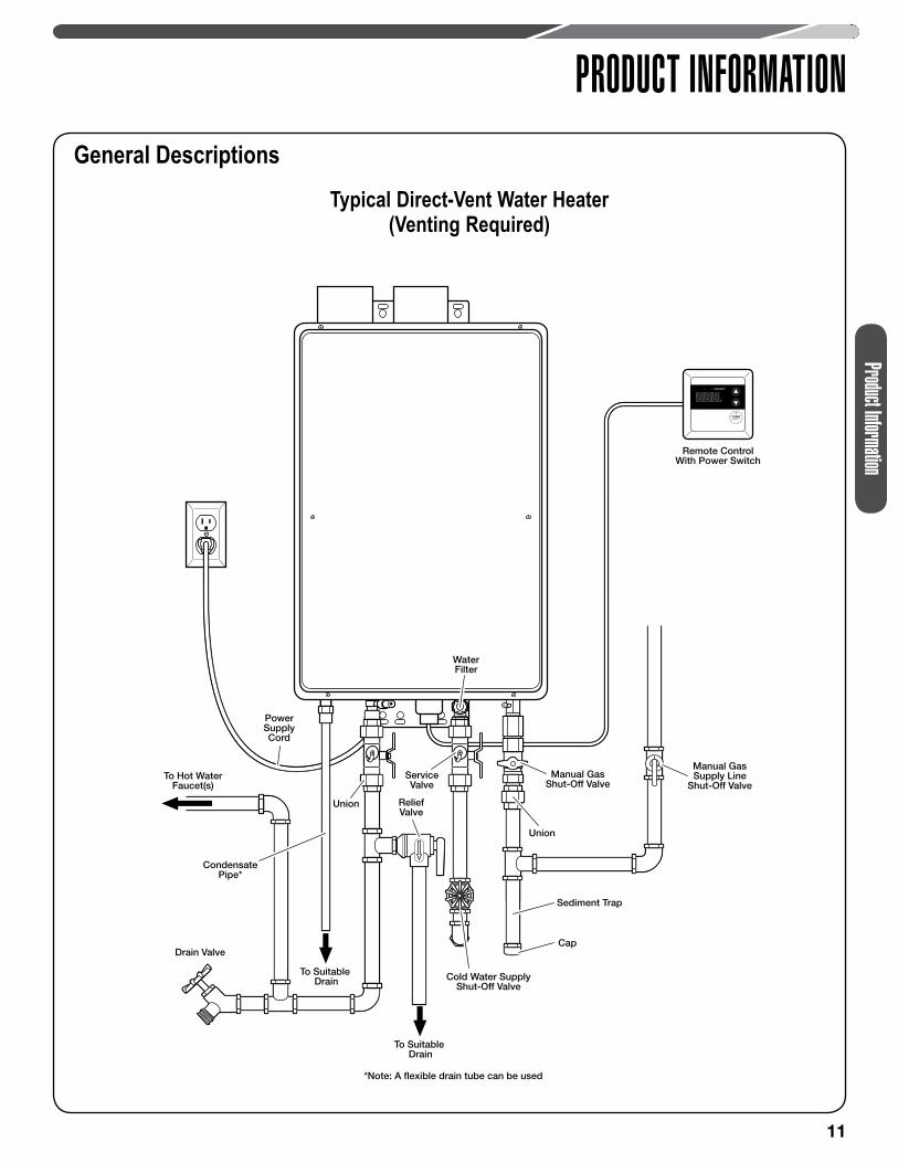
PRODUCT INFORMATIONGeneral Descriptions
Typical Direct-Vent Water Heater (Venting Required)
Product Information
Remote ControlWith Power Switch
To Hot WaterFaucet(s)
Drain Valve
WaterFilter
Cold Water SupplyShut-Off Valve
*Note: A flexible drain tube can be used
To Suitable Drain
To Suitable Drain
PowerSupplyCord
Union
Union
Manual GasSupply Line
Shut-Off ValveManual Gas
Shut-Off Valve
CondensatePipe*
Cap
Sediment Trap
ServiceValve
ReliefValveReliefValve
12
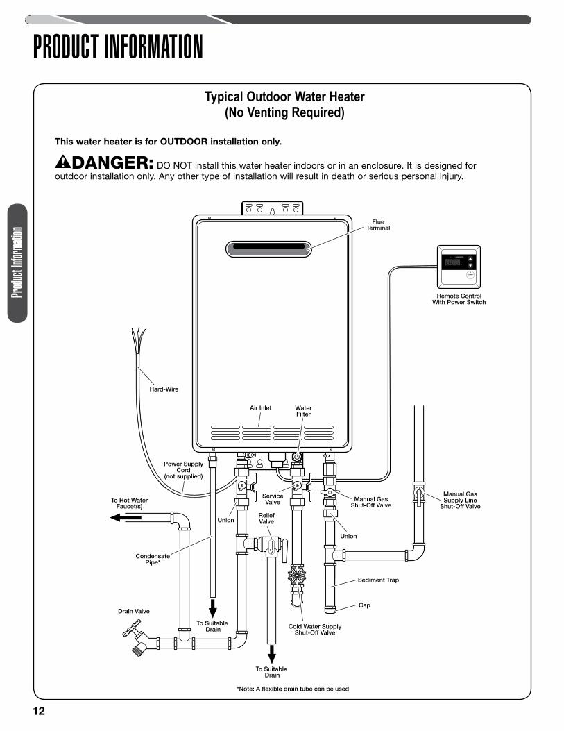
PRODUCT INFORMATIONTypical Outdoor Water Heater
(No Venting Required)
Remote ControlWith Power Switch
To Hot WaterFaucet(s)
Drain Valve
WaterFilter
Air Inlet
Hard-Wire
FlueTerminal
Cold Water SupplyShut-Off Valve
Power SupplyCord
(not supplied)
Union
Union
Manual GasSupply Line
Shut-Off ValveManual Gas
Shut-Off Valve
Cap
Sediment Trap
ServiceValve
ReliefValveReliefValve
*Note: A flexible drain tube can be used
To Suitable Drain
To Suitable Drain
CondensatePipe*
This water heater is for OUTDOOR installation only.
DANGER: DO NOT install this water heater indoors or in an enclosure. It is designed for outdoor installation only. Any other type of installation will result in death or serious personal injury.
Produ
ct Inf
ormati
on
13
Use Instructions
USING YOUR WATER HEATER
WARNING: Flammable vapors can be drawn by air currents from surrounding areas to the water heater. Vapors can ignite causing death, personal injury, or product damage.
• DO NOT store or use flammable or combustible materials (gasoline, paint thinner, adhesives, newspapers, rags, mops, etc.) in the vicinity of the water heater or any other gas appliance. If they must be used, open doors and windows for ventilation, and shut off all gas-burning appliances, including their pilot lights.
• DO turn off manual gas shut-off valve if water heater has been subjected to overheating, fire, flood, physical damage, or if the gas supply fails to shut off.
• DO NOT turn on water heater unless water and gas supplies are completely opened.
• DO NOT turn on water heater if cold water supply shut-off valve is closed.
• If there is any difficulty in understanding or following the operating and care instructions in this manual, it is recommended that you contact a qualified service technician to perform the work.
Safety Precautions
Setting the Water Temperature
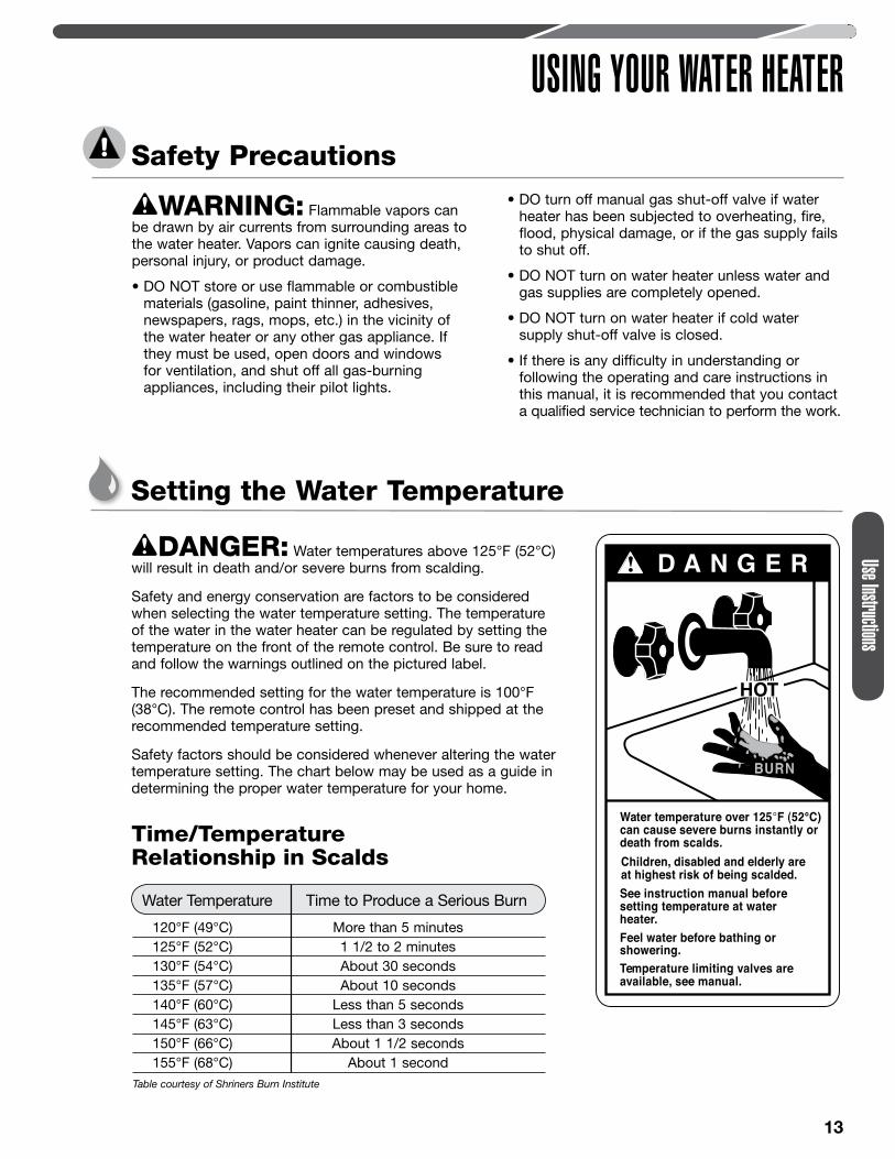
D A N G E R!
HOT
Water temperature over 125°F (52°C)can cause severe burns instantly or death from scalds.Children, disabled and elderly areat highest risk of being scalded.See instruction manual beforesetting temperature at waterheater.Feel water before bathing orshowering.Temperature limiting valves areavailable, see manual.
BURN
Time/Temperature Relationship in Scalds
Water Temperature Time to Produce a Serious Burn
120°F (49°C) More than 5 minutes 125°F (52°C) 1 1/2 to 2 minutes 130°F (54°C) About 30 seconds 135°F (57°C) About 10 seconds 140°F (60°C) Less than 5 seconds 145°F (63°C) Less than 3 seconds 150°F (66°C) About 1 1/2 seconds 155°F (68°C) About 1 secondTable courtesy of Shriners Burn Institute
DANGER: Water temperatures above 125°F (52°C) will result in death and/or severe burns from scalding.
Safety and energy conservation are factors to be considered when selecting the water temperature setting. The temperature of the water in the water heater can be regulated by setting the temperature on the front of the remote control. Be sure to read and follow the warnings outlined on the pictured label.
The recommended setting for the water temperature is 100°F (38°C). The remote control has been preset and shipped at the recommended temperature setting.
Safety factors should be considered whenever altering the water temperature setting. The chart below may be used as a guide in determining the proper water temperature for your home.
14
Use I
nstruc
tions
USING YOUR WATER HEATER
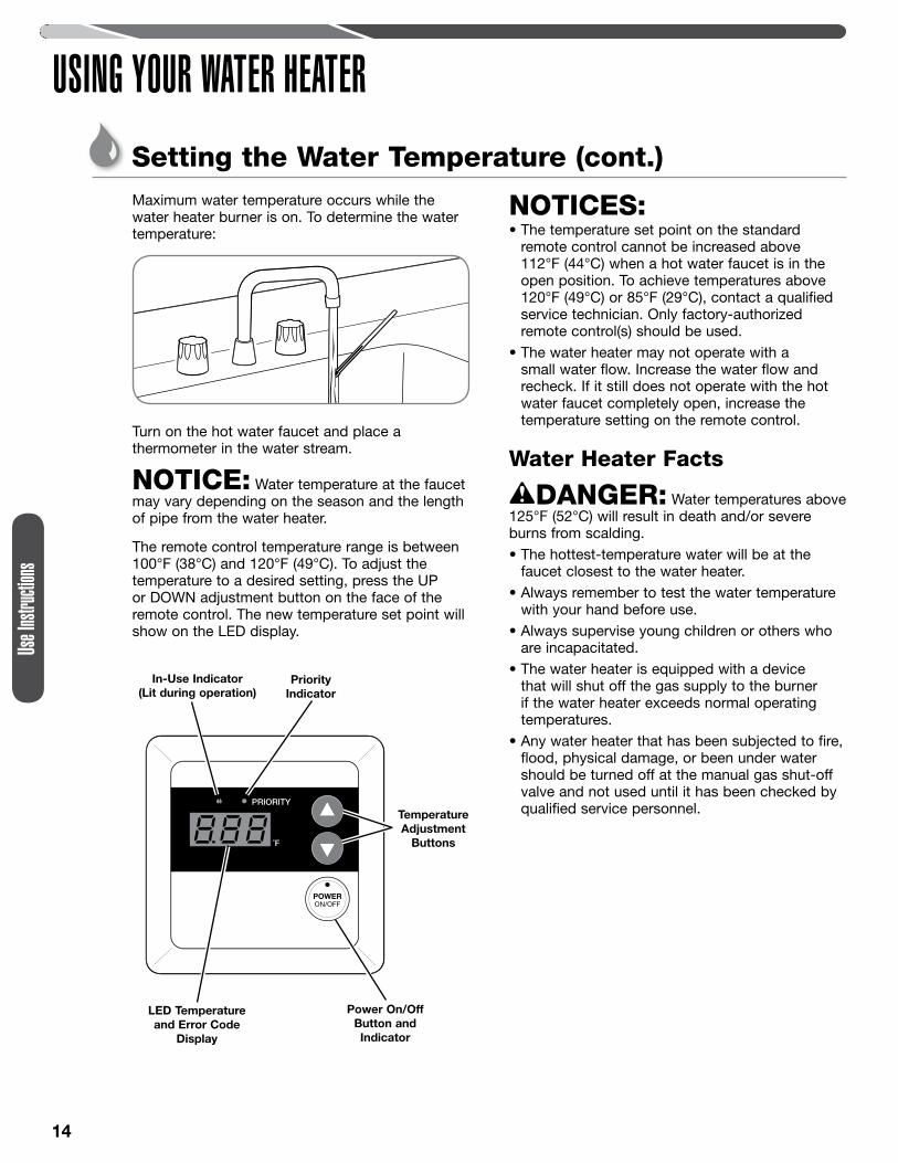
Maximum water temperature occurs while the water heater burner is on. To determine the water temperature:
Turn on the hot water faucet and place a thermometer in the water stream.
NOTICE: Water temperature at the faucet may vary depending on the season and the length of pipe from the water heater.
The remote control temperature range is between 100°F (38°C) and 120°F (49°C). To adjust the temperature to a desired setting, press the UP or DOWN adjustment button on the face of the remote control. The new temperature set point will show on the LED display.
NOTICES:• The temperature set point on the standard
remote control cannot be increased above 112°F (44°C) when a hot water faucet is in the open position. To achieve temperatures above 120°F (49°C) or 85°F (29°C), contact a qualified service technician. Only factory-authorized remote control(s) should be used.
• The water heater may not operate with a small water flow. Increase the water flow and recheck. If it still does not operate with the hot water faucet completely open, increase the temperature setting on the remote control.
Water Heater Facts
DANGER: Water temperatures above 125°F (52°C) will result in death and/or severe burns from scalding.• The hottest-temperature water will be at the
faucet closest to the water heater.• Always remember to test the water temperature
with your hand before use.• Always supervise young children or others who
are incapacitated.• The water heater is equipped with a device
that will shut off the gas supply to the burner if the water heater exceeds normal operating temperatures.
• Any water heater that has been subjected to fire, flood, physical damage, or been under water should be turned off at the manual gas shut-off valve and not used until it has been checked by qualified service personnel.Temperature
Adjustment Buttons
Power On/Off Button and Indicator
LED Temperature and Error Code
Display
In-Use Indicator (Lit during operation)
Priority Indicator
Setting the Water Temperature (cont.)
15
CARING FOR YOUR WATER HEATERWater Heater Inspections
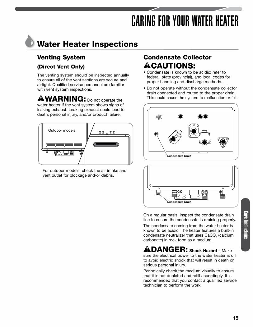
Venting System (Direct Vent Only) The venting system should be inspected annually to ensure all of the vent sections are secure and airtight. Qualified service personnel are familiar with vent system inspections.
WARNING: Do not operate the water heater if the vent system shows signs of leaking exhaust. Leaking exhaust could lead to death, personal injury, and/or product failure.
For outdoor models, check the air intake and vent outlet for blockage and/or debris.
Condensate Collector CAUTIONS:
• Condensate is known to be acidic; refer to federal, state (provincial), and local codes for proper handling and discharge methods.
• Do not operate without the condensate collector drain connected and routed to the proper drain. This could cause the system to malfunction or fail.
On a regular basis, inspect the condensate drain line to ensure the condensate is draining properly. The condensate coming from the water heater is known to be acidic. The heater features a built-in condensate neutralizer that uses CaCO3 (calcium carbonate) in rock form as a medium.
DANGER: Shock Hazard – Make sure the electrical power to the water heater is off to avoid electric shock that will result in death or serious personal injury.Periodically check the medium visually to ensure that it is not depleted and refill accordingly. It is recommended that you contact a qualified service technician to perform the work.
Condensate Drain
Outdoor models
Care Instructions

16
CARING FOR YOUR WATER HEATER
Burner Visually inspect the main burner annually.
DANGER: Shock Hazard – Removing the front cover panel exposes you to live electricity. Electric shock will cause death or serious personal injury.
Remove 6 screws and the unit cover panel.
Turn on a hot water faucet.
While the water heater is operating, inspect the main burner flames through the burner sight glass. The flames should be blue when the main burner is firing.
NOTICE: If the flames are not blue or you observe unusual burner operation, shut off the water heater and contact a qualified service technician.
Turn off the hot water faucet and reinstall the unit cover panel.
4
2
1
BurnerSightGlass
3
Water Heater Inspections (cont.)
Care
Instru
ctions
17
CARING FOR YOUR WATER HEATERCare and Cleaning
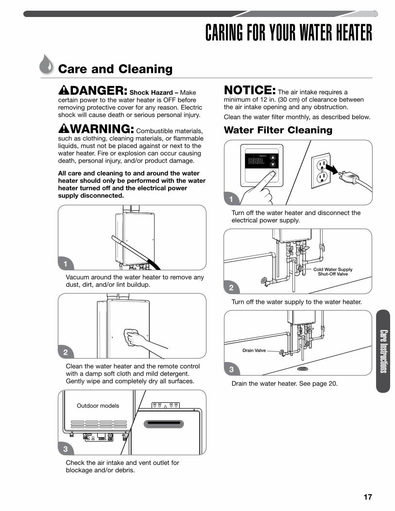
DANGER: Shock Hazard – Make certain power to the water heater is OFF before removing protective cover for any reason. Electric shock will cause death or serious personal injury.
WARNING: Combustible materials, such as clothing, cleaning materials, or flammable liquids, must not be placed against or next to the water heater. Fire or explosion can occur causing death, personal injury, and/or product damage.
All care and cleaning to and around the water heater should only be performed with the water heater turned off and the electrical power supply disconnected.
Vacuum around the water heater to remove any dust, dirt, and/or lint buildup.
Clean the water heater and the remote control with a damp soft cloth and mild detergent. Gently wipe and completely dry all surfaces.
Check the air intake and vent outlet for blockage and/or debris.
NOTICE: The air intake requires a minimum of 12 in. (30 cm) of clearance between the air intake opening and any obstruction.
Clean the water filter monthly, as described below.
Water Filter Cleaning
Turn off the water heater and disconnect the electrical power supply.
Turn off the water supply to the water heater.
Drain the water heater. See page 20.
1
2
1
Drain Valve
3
Cold Water SupplyShut-Off Valve
2
3
Outdoor models
Care Instructions
18
CARING FOR YOUR WATER HEATER
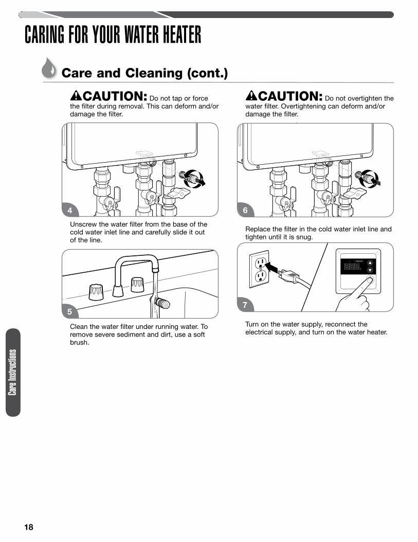
CAUTION: Do not tap or force the filter during removal. This can deform and/or damage the filter.
Unscrew the water filter from the base of the cold water inlet line and carefully slide it out of the line.
Clean the water filter under running water. To remove severe sediment and dirt, use a soft brush.
CAUTION: Do not overtighten the water filter. Overtightening can deform and/or damage the filter.
Replace the filter in the cold water inlet line and tighten until it is snug.
Turn on the water supply, reconnect the electrical supply, and turn on the water heater.
4
75
6
Care and Cleaning (cont.)
Care
Instru
ctions
19
CARING FOR YOUR WATER HEATERPreventive Maintenance
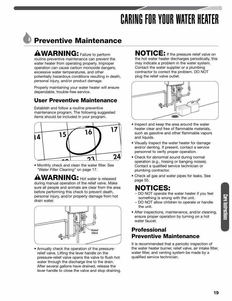
WARNING: Failure to perform routine preventive maintenance can prevent the water heater from operating properly. Improper operation can cause carbon monoxide dangers, excessive water temperatures, and other potentially hazardous conditions resulting in death, personal injury, and/or product damage.
Properly maintaining your water heater will ensure dependable, trouble-free service.
User Preventive MaintenanceEstablish and follow a routine preventive maintenance program. The following suggested items should be included in your program.
• Monthly check and clean the water filter. See “Water Filter Cleaning” on page 17.
WARNING: Hot water is released during manual operation of the relief valve. Make sure all people and animals are clear from the area before performing this check to prevent death, personal injury, and/or property damage from hot drain water.
• Annually check the operation of the pressure-relief valve. Lifting the lever handle on the pressure-relief valve opens the valve to flush hot water through the discharge line to the drain. After several gallons have drained, release the lever handle to close the valve and stop draining.
NOTICE: If the pressure relief valve on the hot water heater discharges periodically, this may indicate a problem in the water system. Contact the water supplier or a plumbing contractor to correct the problem. DO NOT plug the relief valve outlet.
• Inspect and keep the area around the water heater clear and free of flammable materials, such as gasoline and other flammable vapors and liquids.
• Visually inspect the water heater for damage and/or denting. If present, contact a service personnel to verify proper operation.
• Check for abnormal sound during normal operation (e.g., hissing or banging noises). Contact a qualified service technician or plumbing contractor.
• Check all gas and water pipes for leaks. See page 55.
NOTICES: – DO NOT operate the water heater if you feel something is wrong with the unit. – DO NOT allow children to operate or handle the unit.
• After inspections, maintenance, and/or cleaning, ensure proper operation by turning on a hot water faucet.
Professional Preventive Maintenance
It is recommended that a periodic inspection of the water heater burner, relief valve, air intake filter, water filter, and venting system be made by a qualified service technician.
ReliefValve
Care Instructions
20
Care
Instru
ctions
CARING FOR YOUR WATER HEATERDraining the Water Heater
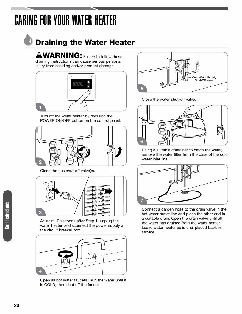
WARNING: Failure to follow these draining instructions can cause serious personal injury from scalding and/or product damage.
Turn off the water heater by pressing the POWER ON/OFF button on the control panel.
Close the gas shut-off valve(s).
At least 10 seconds after Step 1, unplug the water heater or disconnect the power supply at the circuit breaker box.
Open all hot water faucets. Run the water until it is COLD; then shut off the faucet.
Close the water shut-off valve.
Using a suitable container to catch the water, remove the water filter from the base of the cold water inlet line.
Connect a garden hose to the drain valve in the hot water outlet line and place the other end in a suitable drain. Open the drain valve until all the water has drained from the water heater. Leave water heater as is until placed back in service.
1
2
3
4
Cold Water SupplyShut-Off Valve
5
6
7
21
Care Instructions
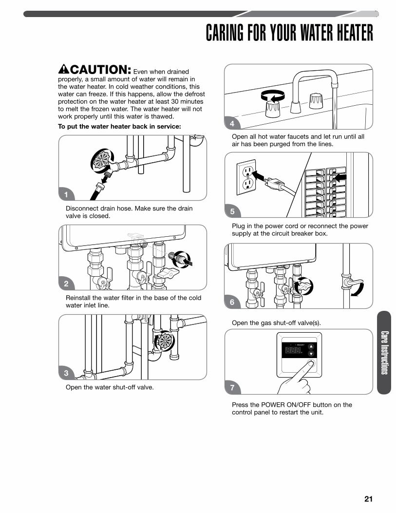
CARING FOR YOUR WATER HEATERCAUTION: Even when drained
properly, a small amount of water will remain in the water heater. In cold weather conditions, this water can freeze. If this happens, allow the defrost protection on the water heater at least 30 minutes to melt the frozen water. The water heater will not work properly until this water is thawed.
To put the water heater back in service:
Disconnect drain hose. Make sure the drain valve is closed.
Reinstall the water filter in the base of the cold water inlet line.
Open the water shut-off valve.
Open all hot water faucets and let run until all air has been purged from the lines.
Plug in the power cord or reconnect the power supply at the circuit breaker box.
Open the gas shut-off valve(s).
Press the POWER ON/OFF button on the control panel to restart the unit.
1
2
3
4
5
6
7
22
CARING FOR YOUR WATER HEATERDraining the Water Heater (cont.)
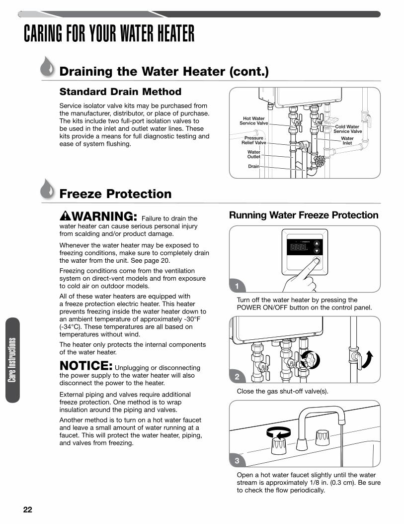
Standard Drain MethodService isolator valve kits may be purchased from the manufacturer, distributor, or place of purchase. The kits include two full-port isolation valves to be used in the inlet and outlet water lines. These kits provide a means for full diagnostic testing and ease of system flushing.
Freeze Protection
WARNING: Failure to drain the water heater can cause serious personal injury from scalding and/or product damage.
Whenever the water heater may be exposed to freezing conditions, make sure to completely drain the water from the unit. See page 20.
Freezing conditions come from the ventilation system on direct-vent models and from exposure to cold air on outdoor models.
All of these water heaters are equipped with a freeze protection electric heater. This heater prevents freezing inside the water heater down to an ambient temperature of approximately -30°F (-34°C). These temperatures are all based on temperatures without wind.
The heater only protects the internal components of the water heater.
NOTICE: Unplugging or disconnecting the power supply to the water heater will also disconnect the power to the heater.
External piping and valves require additional freeze protection. One method is to wrap insulation around the piping and valves.
Another method is to turn on a hot water faucet and leave a small amount of water running at a faucet. This will protect the water heater, piping, and valves from freezing.
Running Water Freeze Protection
Turn off the water heater by pressing the POWER ON/OFF button on the control panel.
Close the gas shut-off valve(s).
Open a hot water faucet slightly until the water stream is approximately 1/8 in. (0.3 cm). Be sure to check the flow periodically.
Cold Water Service Valve
Hot WaterService Valve
PressureRelief Valve
PressureRelief Valve
Water OutletWaterOutlet
Water Inlet
WaterInlet
DrainDrain
1
2
3
Care
Instru
ctions
23
CARING FOR YOUR WATER HEATERVacation and Extended Shutdown
WARNING: Failure to drain the water heater can cause serious personal injury from scalding and/or product damage.
If the water heater is to remain idle for an extended period of time, the power and water to the heater should be turned off.
The water heater and piping should be drained if they might be subjected to freezing temperatures. See “Freeze Protection” section on page 22.
After an extended shutdown, the water heater’s operation and controls should be checked by a qualified service technician.
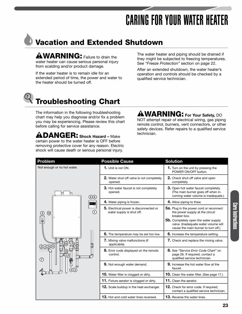
Troubleshooting ChartThe information in the following troubleshooting chart may help you diagnose and/or fix a problem you may be experiencing. Please review this chart before calling for service assistance.
DANGER: Shock Hazard – Make certain power to the water heater is OFF before removing protective cover for any reason. Electric shock will cause death or serious personal injury.
WARNING: For Your Safety, DO NOT attempt repair of electrical wiring, gas piping remote control, burners, vent connectors, or other safety devices. Refer repairs to a qualified service technician.
Problem Possible Cause SolutionNot enough or no hot water. 1. Unit is not ON. 1. Turn on the unit by pressing the
POWER ON/OFF button.
2. Water shut-off valve is not completely opened.
2. Check shut-off valve and open completely.
3. Hot water faucet is not completely opened.
3. Open hot water faucet completely. (The main burner goes off when in-coming water volume is inadequate.)
4. Water piping is frozen. 4. Allow piping to thaw.
5. Electrical power is disconnected or water supply is shut off.
5a. Plug in the power cord or reconnectthe power supply at the circuit breaker box.
5b. Completely open the water supply valve. (Inadequate water volume will cause the main burner to turn off.)
6. The temperature may be set too low. 6. Increase the temperature setting.
7. Mixing valve malfunctions (if applicable).
7. Check and replace the mixing valve.
8. Error code displayed on the remote control.
8. See “Service Error Code Chart” on page 26. If required, contact a qualified service technician.
9. Not enough water demand. 9. Increase the hot water flow at the faucet.
10. Water filter is clogged or dirty. 10. Clean the water filter. (See page 17.)
11. Fixture aerator is clogged or dirty. 11. Clean the aerator.
12. Scale buildup in the heat exchanger. 12. Check for error code. If required, contact a qualified service technician.
13. Hot and cold water lines reversed. 13. Reverse the water lines.
Care Instructions
24
Care
Instru
ctions
CARING FOR YOUR WATER HEATER
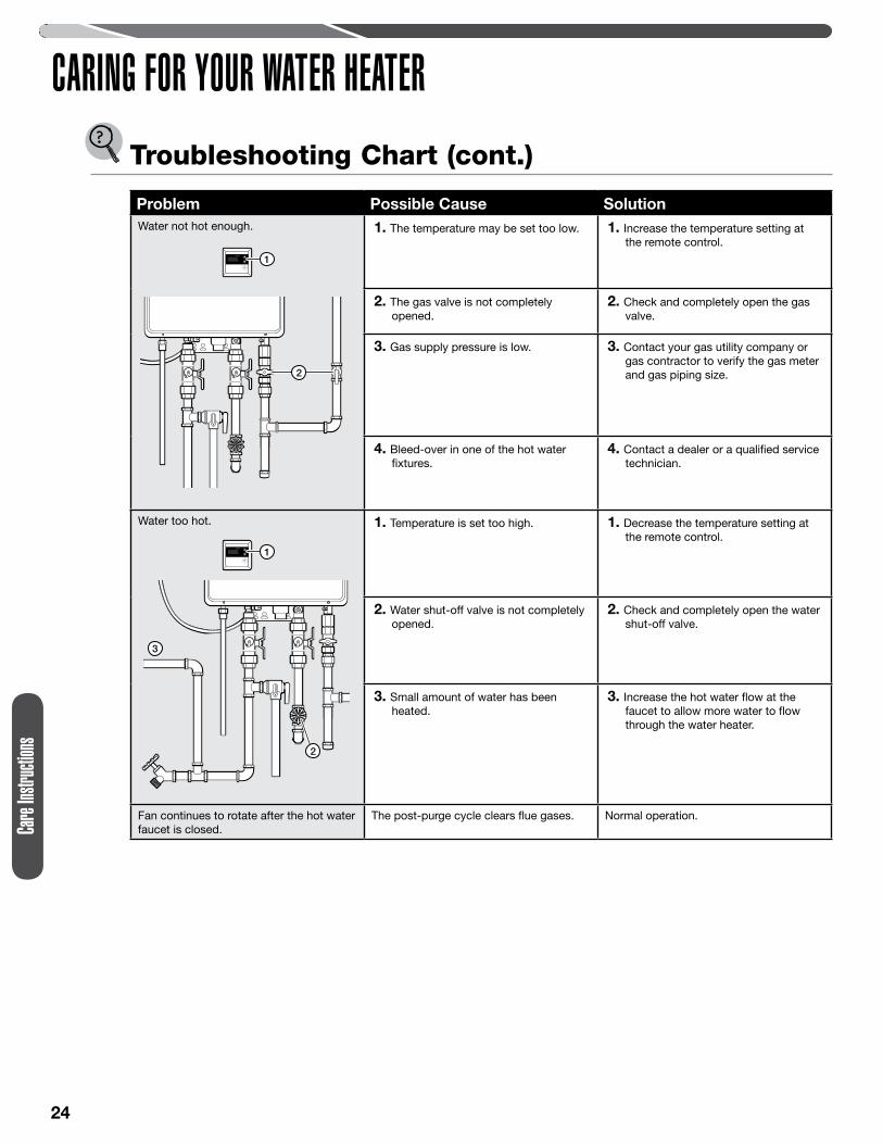
Problem Possible Cause SolutionWater not hot enough. 1. The temperature may be set too low. 1. Increase the temperature setting at
the remote control.
2. The gas valve is not completely opened.
2. Check and completely open the gas valve.
3. Gas supply pressure is low. 3. Contact your gas utility company or gas contractor to verify the gas meter and gas piping size.
4. Bleed-over in one of the hot water fixtures.
4. Contact a dealer or a qualified service technician.
Water too hot. 1. Temperature is set too high. 1. Decrease the temperature setting at the remote control.
2. Water shut-off valve is not completely opened.
2. Check and completely open the water shut-off valve.
3. Small amount of water has been heated.
3. Increase the hot water flow at the faucet to allow more water to flow through the water heater.
Fan continues to rotate after the hot water faucet is closed.
The post-purge cycle clears flue gases. Normal operation.
1
2
3
1
2
Troubleshooting Chart (cont.)
25
Care Instructions
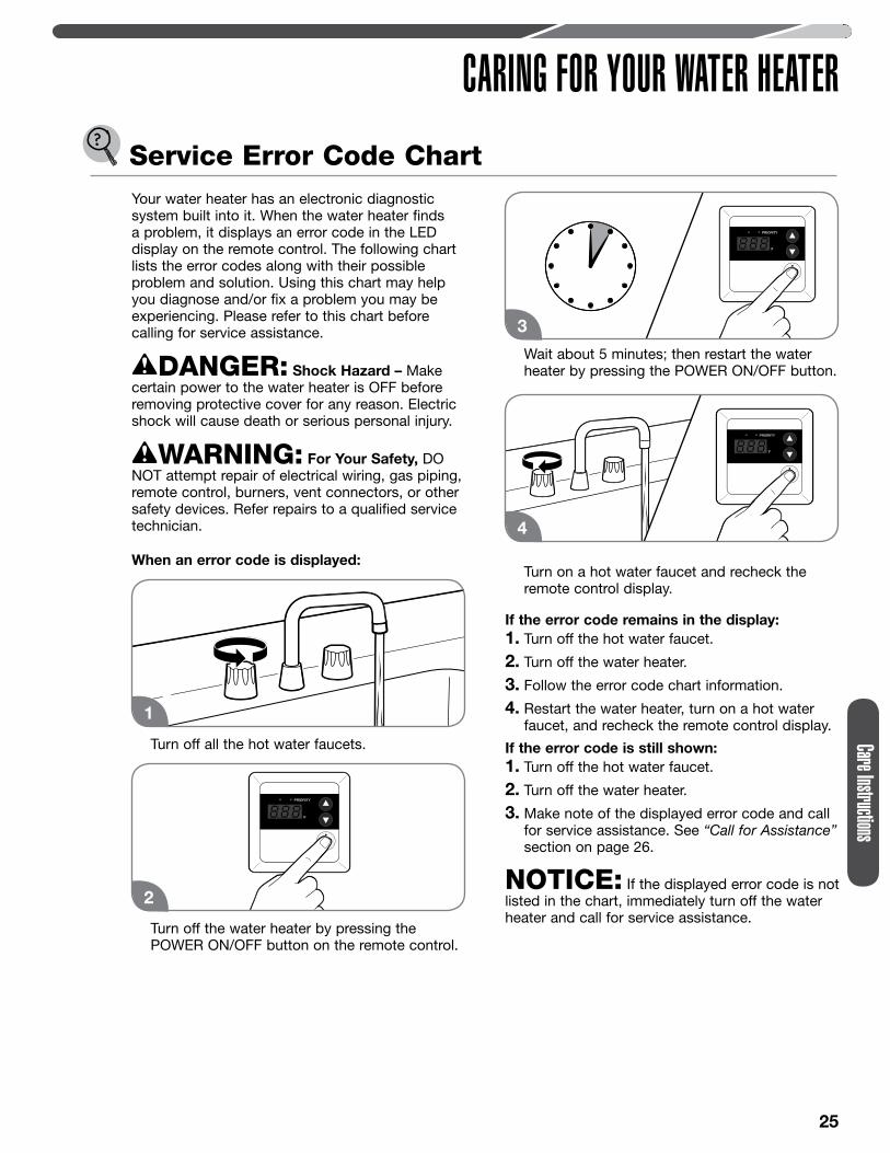
CARING FOR YOUR WATER HEATERService Error Code ChartYour water heater has an electronic diagnostic system built into it. When the water heater finds a problem, it displays an error code in the LED display on the remote control. The following chart lists the error codes along with their possible problem and solution. Using this chart may help you diagnose and/or fix a problem you may be experiencing. Please refer to this chart before calling for service assistance.
DANGER: Shock Hazard – Make certain power to the water heater is OFF before removing protective cover for any reason. Electric shock will cause death or serious personal injury.
WARNING: For Your Safety, DO NOT attempt repair of electrical wiring, gas piping, remote control, burners, vent connectors, or other safety devices. Refer repairs to a qualified service technician.
When an error code is displayed:
Turn off all the hot water faucets.
Turn off the water heater by pressing the POWER ON/OFF button on the remote control.
Wait about 5 minutes; then restart the water heater by pressing the POWER ON/OFF button.
Turn on a hot water faucet and recheck the remote control display.
If the error code remains in the display:1. Turn off the hot water faucet.
2. Turn off the water heater.
3. Follow the error code chart information.
4. Restart the water heater, turn on a hot water faucet, and recheck the remote control display.
If the error code is still shown:1. Turn off the hot water faucet.
2. Turn off the water heater.
3. Make note of the displayed error code and call for service assistance. See “Call for Assistance” section on page 26.
NOTICE: If the displayed error code is not listed in the chart, immediately turn off the water heater and call for service assistance.
1
2
3
4
26
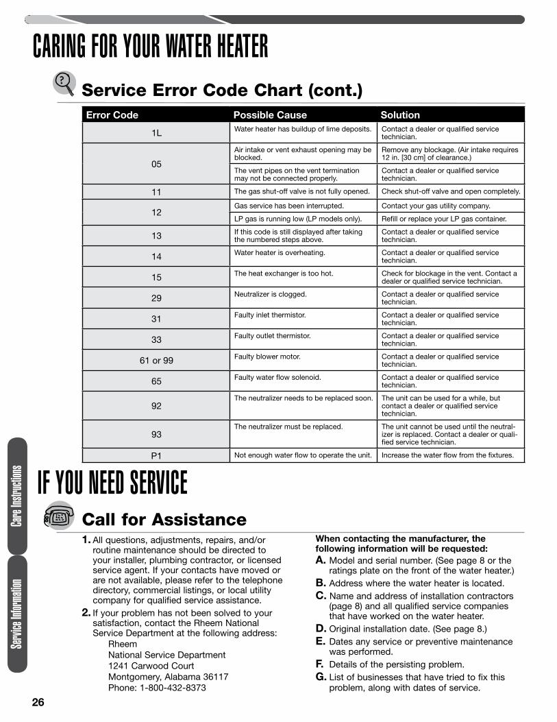
Error Code Possible Cause Solution
1L Water heater has buildup of lime deposits. Contact a dealer or qualified service technician.
05
Air intake or vent exhaust opening may be blocked.
Remove any blockage. (Air intake requires 12 in. [30 cm] of clearance.)
The vent pipes on the vent termination may not be connected properly.
Contact a dealer or qualified service technician.
11 The gas shut-off valve is not fully opened. Check shut-off valve and open completely.
12Gas service has been interrupted. Contact your gas utility company.
LP gas is running low (LP models only). Refill or replace your LP gas container.
13 If this code is still displayed after taking the numbered steps above.
Contact a dealer or qualified service technician.
14 Water heater is overheating. Contact a dealer or qualified service technician.
15 The heat exchanger is too hot. Check for blockage in the vent. Contact a dealer or qualified service technician.
29 Neutralizer is clogged. Contact a dealer or qualified service technician.
31 Faulty inlet thermistor. Contact a dealer or qualified service technician.
33 Faulty outlet thermistor. Contact a dealer or qualified service technician.
61 or 99 Faulty blower motor. Contact a dealer or qualified service technician.
65 Faulty water flow solenoid. Contact a dealer or qualified service technician.
92The neutralizer needs to be replaced soon. The unit can be used for a while, but
contact a dealer or qualified service technician.
93The neutralizer must be replaced. The unit cannot be used until the neutral-
izer is replaced. Contact a dealer or quali-fied service technician.
P1 Not enough water flow to operate the unit. Increase the water flow from the fixtures.
Servi
ce Inf
ormati
on
Service Error Code Chart (cont.)
Care
Instru
ctions
CARING FOR YOUR WATER HEATER
1. All questions, adjustments, repairs, and/or routine maintenance should be directed to your installer, plumbing contractor, or licensed service agent. If your contacts have moved or are not available, please refer to the telephone directory, commercial listings, or local utility company for qualified service assistance.
2. If your problem has not been solved to your satisfaction, contact the Rheem National Service Department at the following address:
RheemNational Service Department1241 Carwood CourtMontgomery, Alabama 36117Phone: 1-800-432-8373
When contacting the manufacturer, the following information will be requested:A. Model and serial number. (See page 8 or the
ratings plate on the front of the water heater.)B. Address where the water heater is located.C. Name and address of installation contractors
(page 8) and all qualified service companies that have worked on the water heater.
D. Original installation date. (See page 8.)E. Dates any service or preventive maintenance
was performed.F. Details of the persisting problem.G. List of businesses that have tried to fix this
problem, along with dates of service.
Call for Assistance
IF YOU NEED SERVICE
INSTALLATION INSTRUCTIONS
FOR THE CONTRACTOR
Installation
28
INSTALLATION INSTRUCTIONS
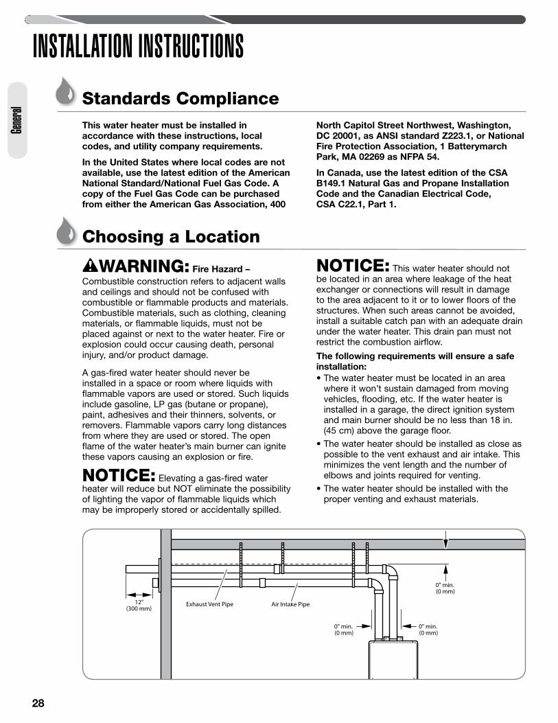
Exhaust Vent Pipe Air Intake Pipe
0" min.(0 mm)
0" min.(0 mm)
0" min.(0 mm)
12"(300 mm)
Standards ComplianceThis water heater must be installed in accordance with these instructions, local codes, and utility company requirements.
In the United States where local codes are not available, use the latest edition of the American National Standard/National Fuel Gas Code. A copy of the Fuel Gas Code can be purchased from either the American Gas Association, 400
North Capitol Street Northwest, Washington, DC 20001, as ANSI standard Z223.1, or National Fire Protection Association, 1 Batterymarch Park, MA 02269 as NFPA 54.
In Canada, use the latest edition of the CSA B149.1 Natural Gas and Propane Installation Code and the Canadian Electrical Code, CSA C22.1, Part 1.
Choosing a Location
WARNING: Fire Hazard –Combustible construction refers to adjacent walls and ceilings and should not be confused with combustible or flammable products and materials. Combustible materials, such as clothing, cleaning materials, or flammable liquids, must not be placed against or next to the water heater. Fire or explosion could occur causing death, personal injury, and/or product damage.
A gas-fired water heater should never be installed in a space or room where liquids with flammable vapors are used or stored. Such liquids include gasoline, LP gas (butane or propane), paint, adhesives and their thinners, solvents, or removers. Flammable vapors carry long distances from where they are used or stored. The open flame of the water heater’s main burner can ignite these vapors causing an explosion or fire.
NOTICE: Elevating a gas-fired water heater will reduce but NOT eliminate the possibility of lighting the vapor of flammable liquids which may be improperly stored or accidentally spilled.
NOTICE: This water heater should not be located in an area where leakage of the heat exchanger or connections will result in damage to the area adjacent to it or to lower floors of the structures. When such areas cannot be avoided, install a suitable catch pan with an adequate drain under the water heater. This drain pan must not restrict the combustion airflow.
The following requirements will ensure a safe installation:• The water heater must be located in an area
where it won’t sustain damaged from moving vehicles, flooding, etc. If the water heater is installed in a garage, the direct ignition system and main burner should be no less than 18 in. (45 cm) above the garage floor.
• The water heater should be installed as close as possible to the vent exhaust and air intake. This minimizes the vent length and the number of elbows and joints required for venting.
• The water heater should be installed with the proper venting and exhaust materials.
Gener
al
29
INSTALLATION INSTRUCTIONSGeneral
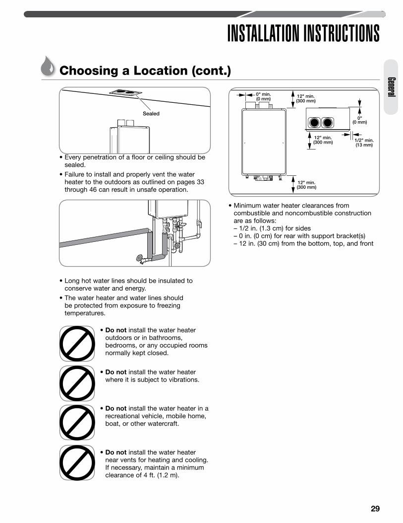
• Every penetration of a floor or ceiling should be sealed.
• Failure to install and properly vent the water heater to the outdoors as outlined on pages 33 through 46 can result in unsafe operation.
• Long hot water lines should be insulated to conserve water and energy.
• The water heater and water lines should be protected from exposure to freezing temperatures.
• Minimum water heater clearances from combustible and noncombustible construction are as follows: – 1/2 in. (1.3 cm) for sides – 0 in. (0 cm) for rear with support bracket(s) – 12 in. (30 cm) from the bottom, top, and front
12" min.(300 mm)
12" min.(300 mm) 1/2" min.
(13 mm)
12" min.(300 mm)
0"(0 mm)
0" min.(0 mm)
Sealed
• Do not install the water heater outdoors or in bathrooms, bedrooms, or any occupied rooms normally kept closed.
• Do not install the water heater where it is subject to vibrations.
• Do not install the water heater in a recreational vehicle, mobile home, boat, or other watercraft.
• Do not install the water heater near vents for heating and cooling. If necessary, maintain a minimum clearance of 4 ft. (1.2 m).
Choosing a Location (cont.)
30
INSTALLATION INSTRUCTIONSGe
neral
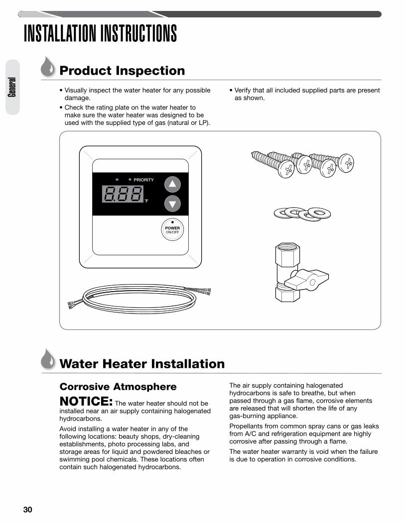
Product Inspection• Visually inspect the water heater for any possible
damage.• Check the rating plate on the water heater to
make sure the water heater was designed to be used with the supplied type of gas (natural or LP).
• Verify that all included supplied parts are present as shown.
Water Heater Installation
Corrosive Atmosphere
NOTICE: The water heater should not be installed near an air supply containing halogenated hydrocarbons.
Avoid installing a water heater in any of the following locations: beauty shops, dry-cleaning establishments, photo processing labs, and storage areas for liquid and powdered bleaches or swimming pool chemicals. These locations often contain such halogenated hydrocarbons.
The air supply containing halogenated hydrocarbons is safe to breathe, but when passed through a gas flame, corrosive elements are released that will shorten the life of any gas-burning appliance.
Propellants from common spray cans or gas leaks from A/C and refrigeration equipment are highly corrosive after passing through a flame.
The water heater warranty is void when the failure is due to operation in corrosive conditions.
31
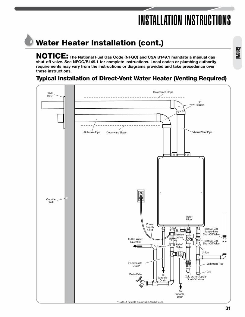
INSTALLATION INSTRUCTIONSGeneralNOTICE: The National Fuel Gas Code (NFGC) and CSA B149.1 mandate a manual gas
shut-off valve. See NFGC/B149.1 for complete instructions. Local codes or plumbing authority requirements may vary from the instructions or diagrams provided and take precedence over these instructions.
Typical Installation of Direct-Vent Water Heater (Venting Required)
To Hot WaterFaucet(s)
Drain Valve
WallPlate
WaterFilter
Cold Water SupplyShut-O� Valve
PowerSupply
Cord
UnionUnion
Union
Manual GasSupply Line
Shut-O� Valve
Downward Slope
Downward Slope
Manual GasShut-O� Valve
Cap
Sediment Trap
OutsideWall
91˚Elbow
ServiceValve
ServiceValve
ReliefValveReliefValve
*Note: A �exible drain tube can be used
ToSuitable
Drain
ToSuitable
Drain
Condensate Drain*
Air Intake Pipe Exhaust Vent Pipe
Water Heater Installation (cont.)
32
Gener
al
INSTALLATION INSTRUCTIONSWater Heater Installation (cont.)
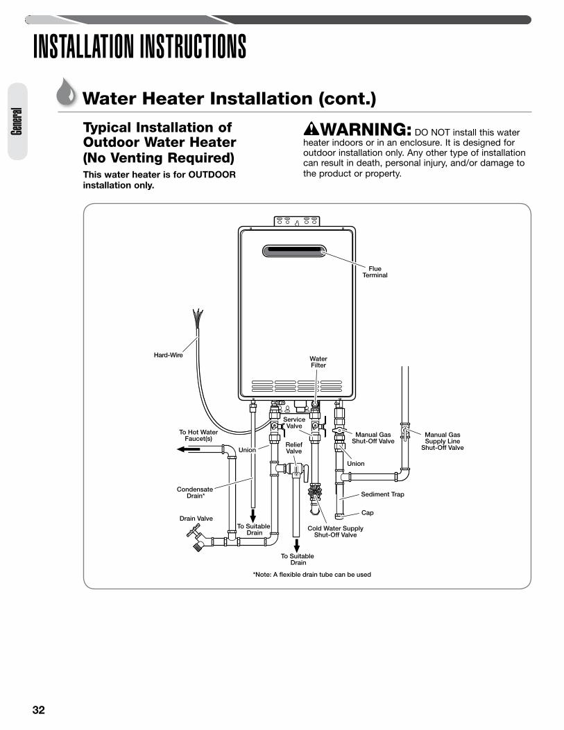
Typical Installation of Outdoor Water Heater (No Venting Required)This water heater is for OUTDOOR installation only.
*Note: A flexible drain tube can be used
To Suitable Drain
To Suitable Drain
To Hot WaterFaucet(s)
Drain Valve
Cold Water SupplyShut-Off Valve
Hard-Wire
Union
Manual GasSupply Line
Shut-Off Valve
FlueTerminal
Cap
Sediment Trap
Manual GasShut-Off Valve
WaterFilter
UnionUnion
ServiceValve
ServiceValve
ReliefValveReliefValve
Condensate Drain*
WARNING: DO NOT install this water heater indoors or in an enclosure. It is designed for outdoor installation only. Any other type of installation can result in death, personal injury, and/or damage to the product or property.
33
General
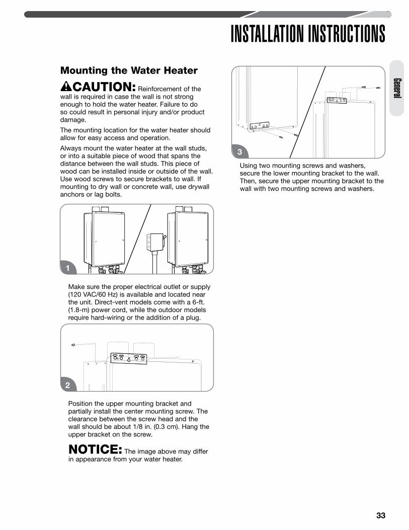
INSTALLATION INSTRUCTIONSMounting the Water Heater
CAUTION: Reinforcement of the wall is required in case the wall is not strong enough to hold the water heater. Failure to do so could result in personal injury and/or product damage.
The mounting location for the water heater should allow for easy access and operation.
Always mount the water heater at the wall studs, or into a suitable piece of wood that spans the distance between the wall studs. This piece of wood can be installed inside or outside of the wall. Use wood screws to secure brackets to wall. If mounting to dry wall or concrete wall, use drywall anchors or lag bolts.
Make sure the proper electrical outlet or supply (120 VAC/60 Hz) is available and located near the unit. Direct-vent models come with a 6-ft. (1.8-m) power cord, while the outdoor models require hard-wiring or the addition of a plug.
Position the upper mounting bracket and partially install the center mounting screw. The clearance between the screw head and the wall should be about 1/8 in. (0.3 cm). Hang the upper bracket on the screw.
NOTICE: The image above may differ in appearance from your water heater.
Using two mounting screws and washers, secure the lower mounting bracket to the wall. Then, secure the upper mounting bracket to the wall with two mounting screws and washers.
2
1
3
34
INSTALLATION INSTRUCTIONSVenting for Direct-Vent Water Heater
DANGER: Failure to properly vent the water heater to the outdoors as outlined in this Venting section will result in death or serious personal injury. To avoid the risk of fire, explosion, or asphyxiation from carbon monoxide, NEVER operate the water heater unless it is properly vented and has adequate air supply for proper operation as outlined in this Venting section.
WARNING: Refer to page 29 for required clearances to combustible materials. Improper clearances can cause explosion or fire resulting in death, personal injury, and/or product damage.
CAUTIONS: • Check to make sure flue gases do not recirculate
into the air intake terminal when using direct venting. If the water heater is having service issues, flue recirculation may be a contributing factor.
• Even when the minimum vent terminal separation distances are followed, recirculation may still occur depending upon the location outside the building, the distance from other buildings, proximity to corners, weather conditions, wind patterns, and snow depth.
• Periodically check to make sure that flue recirculation is not occurring. Signs of flue gas recirculation include frosted or frozen intake terminals and condensate in the intake terminal and venting system.
• Correction to flue recirculation may involve angling the intake away from the exhaust terminal and increasing the distance between them. Check to be sure the intake and exhaust terminals are not obstructed, especially during periods of below-freezing weather.
Venting RequirementsThe installation of venting must comply with national codes, local codes, and the vent manufacturer’s instructions.The vent exhaust and air intake must be vented outside as described in these instructions. DO NOT vent this water heater through a chimney. It must be vented separately from all other appliances.
NOTICE: The unit can be vented using only the following recommended pipe material. Use only 2- or 3-inch diameter pipe. Refer to local codes for restrictions on the use of PVC, CPVC, or ABS pipe and fittings. All exhaust venting materials for product installed in Canada must meet ULC-S636.
Acceptable materials or equivalent:PVC (Schedule 40, ASTM D-1785)CPVC (Schedule 40, ASTM F-441)ABS (Schedule 40, ASTM D-2661) (Not permitted
in Canada)The fittings, other than the VENT TERMINAL, should be equivalent to the following:PVC (Schedule 40 DWV, ASTM D-2665)CPVC (Schedule 40 DWV, ASTM F-438)ABS (Schedule 40 DWV, ASTM D-2661) (Not permitted in Canada)Category III Stainless SteelDO NOT USE Schedule 20, Cell Core, Drain Pipe, Galvanized, Aluminum, or B-Vent.
Recommended Vent LengthsBefore starting the vent installation, careful planning should be given to the routing and termination of the vent pipes. The length of the vent pipes (inlet and outlet) should be kept to a minimum. Also, see pages 37–38 and 44 for vent terminal placement. Refer to the maximum and minimum vent length charts for the pipe sizes that can be used and the total equivalent length of pipe that can be used. Do not exceed equivalent length of pipe in maximum vent length chart.
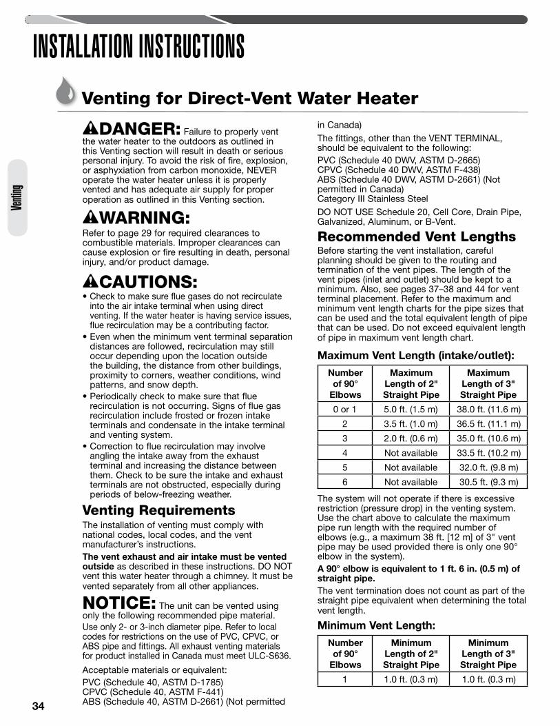
Maximum Vent Length (intake/outlet):
Number of 90°
Elbows
Maximum Length of 2" Straight Pipe
Maximum Length of 3" Straight Pipe
0 or 1 5.0 ft. (1.5 m) 38.0 ft. (11.6 m)
2 3.5 ft. (1.0 m) 36.5 ft. (11.1 m)
3 2.0 ft. (0.6 m) 35.0 ft. (10.6 m)
4 Not available 33.5 ft. (10.2 m)
5 Not available 32.0 ft. (9.8 m)
6 Not available 30.5 ft. (9.3 m)
The system will not operate if there is excessive restriction (pressure drop) in the venting system. Use the chart above to calculate the maximum pipe run length with the required number of elbows (e.g., a maximum 38 ft. [12 m] of 3" vent pipe may be used provided there is only one 90° elbow in the system).A 90° elbow is equivalent to 1 ft. 6 in. (0.5 m) of straight pipe. The vent termination does not count as part of the straight pipe equivalent when determining the total vent length.
Minimum Vent Length:
Number of 90°
Elbows
Minimum Length of 2" Straight Pipe
Minimum Length of 3" Straight Pipe
1 1.0 ft. (0.3 m) 1.0 ft. (0.3 m)
Venti
ng
35
INSTALLATION INSTRUCTIONSVenting
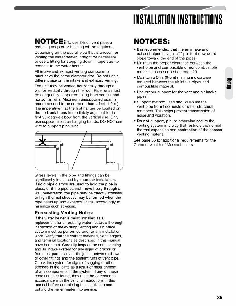
NOTICE: To use 2-inch vent pipe, a reducing adapter or bushing will be required.Depending on the size of pipe that is chosen for venting the water heater, it might be necessary to use a fitting for stepping down in pipe size, to connect to the water heater.All intake and exhaust venting components must have the same diameter size. Do not use a different size on the intake and exhaust venting.The unit may be vented horizontally through a wall or vertically through the roof. Pipe runs must be adequately supported along both vertical and horizontal runs. Maximum unsupported span is recommended to be no more than 4 feet (1.2 m). It is imperative that the first hanger be located on the horizontal runs immediately adjacent to the first 90-degree elbow from the vertical rise. Only use support isolation hanging bands. DO NOT use wire to support pipe runs.
Stress levels in the pipe and fittings can be significantly increased by improper installation. If rigid pipe clamps are used to hold the pipe in place, or if the pipe cannot move freely through a wall penetration, the pipe may be directly stresses, or high thermal stresses may be formed when the pipe heats up and expands. Install accordingly to minimize such stresses.
Preexisting Venting Notes:If the water heater is being installed as a replacement for an existing water heater, a thorough inspection of the existing venting and air intake system must be performed prior to any installation work. Verify that the correct materials, vent lengths, and terminal locations as described in this manual have been met. Carefully inspect the entire venting and air intake system for any signs of cracks or fractures, particularly at the joints between elbows or other fittings and the straight runs of vent pipe. Check the system for signs of sagging or other stresses in the joints as a result of misalignment of any components in the system. If any of these conditions are found, they must be corrected in accordance with the venting instructions in this manual before completing the installation and putting the water heater into service.
NOTICES: • It is recommended that the air intake and
exhaust pipes have a 1/4" per foot downward slope toward the end of the pipes.
• Maintain the proper clearance between the vent pipe and combustible or noncombustible materials as described on page 29.
• Maintain a 0-in. (0-cm) minimum clearance required between the air intake pipes and combustible material.
• Use proper support for the vent and air intake pipes.
• Support method used should isolate the vent pipe from floor joists or other structural members. This helps prevent transmission of noise and vibration.
• Do not support, pin, or otherwise secure the venting system in a way that restricts the normal thermal expansion and contraction of the chosen venting material.
See page 36 for additional requirements for the Commonwealth of Massachusetts.
36
Venti
ng
INSTALLATION INSTRUCTIONSVenting for Direct-Vent Water Heater (cont.)
In the Commonwealth of MassachusettsThe Commonwealth of Massachusetts requires compliance with regulation 248 CMR 4.00 and 5.00 for installation of through-the-wall vented gas appliances as follows:
5.08: Modifications to NFPA–54, Chapter 10
(1) Revise NFPA–54 section 10.5.4.2 by adding a second exception as follows:
Existing chimneys shall be permitted to have their use continued when a gas conversion burner is installed, and shall be equipped with a manual reset device that will automatically shut off the gas to the burner in the event of a sustained back-draft.
(2) Revise 10.8.3 by adding the following additional requirements:
(a) For all side-wall, horizontally vented, gas-fueled equipment installed in every dwelling, building, or structure used in whole or part for residential purposes, including those owned or operated by the Commonwealth and where the side-wall exhaust vent termination is less than seven (7) feet above finished grade in the area of the venting, including but not limited to decks and porches, the following requirements shall be satisfied.
1. INSTALLATION OF CARBON MONOXIDE DETECTORS. At the time of installation of the side-wall, horizontally vented, gas-fueled equipment, the installing plumber or gas fitter shall observe that a hard-wired carbon monoxide detector with an alarm and battery backup is installed on the floor level where the gas equipment is to be installed. In addition, the installing plumber or gas fitter shall observe that a battery-operated or hard-wired carbon monoxide detector with an alarm is installed on each additional level of the dwelling, building, or structure served by the side-wall, horizontally vented, gas-fueled equipment. It shall be the responsibility of the property owner to secure the services of qualified licensed professionals for the installation of hard-wired carbon monoxide detectors.
a. In the event that the side-wall, horizontally vented, gas-fueled equipment is installed in a crawl space or an attic, the hard-wired carbon monoxide detector with alarm and battery backup may be installed on the next adjacent floor level.
b. In the event that the requirements of this subdivision cannot be met at the time of completion of installation, the owner shall have a period of thirty (30) days to comply with the above requirements, provided, however, that during said thirty (30) day period, a battery-operated carbon monoxide detector with an alarm shall be installed.
2. APPROVED CARBON MONOXIDE DETECTORS. Each carbon monoxide detector as required in accordance with the above provisions shall comply with NFPA 720 and be ANSI/UL 2034-listed and IAS-certified.
3. SIGNAGE. A metal or plastic identification plate shall be permanently mounted to the exterior of the building at a minimum height of eight (8) feet above grade directly in line with the exhaust vent terminal for the horizontally vented, gas-fueled heating appliance or equipment. The sign shall read, in print size no less than one-half (1/2) inch in size, “GAS VENT DIRECTLY BELOW. KEEP CLEAR OF ALL OBSTRUCTIONS.”
4. INSPECTION. The state or local gas inspector of the side-wall, horizontally vented, gas-fueled equipment shall not approve the installation unless, upon inspection, the inspector observes carbon monoxide detectors and signage installed in accordance with the provisions of 248 CMR 5.08 (2)(a)(1 through 4).
(b) EXEMPTIONS: The following equipment is exempt from 248 CMR 5.08 (2)(a)(1 through 4):
1. The equipment listed in Chapter 10 entitled “Equipment Not Required To Be Vented” in the most current edition of NFPA 54 as adopted by the Board, and
2. Product-approved side-wall, horizontally vented, gas-fueled equipment installed in a room or structure separate from the dwelling, building, or structure used in whole or in part for residential purposes.
(c) MANUFACTURER REQUIREMENTS – GAS EQUIPMENT VENTING SYSTEM PROVIDED. When the manufacturer of product-approved side-wall, horizontally vented, gas-fueled equipment provides a venting system design or venting system components with the equipment, the instructions provided by the manufacturer for installation of the equipment and the venting system shall include:
1. Detailed instructions for the installation of the venting system design or the venting system components; and
2. A complete parts list for the venting system design or venting system.
(d) MANUFACTURER REQUIREMENTS – GAS EQUIPMENT VENTING SYSTEM NOT PROVIDED. When the manufacturer of product-approved side-wall, horizontally vented, gas-fueled equipment does not provide the parts for venting the flue gases, but identifies “special venting systems,” the following requirements shall be satisfied by the manufacturer:
1. The referenced “special venting systems” instructions shall be included with the appliance or equipment installation instructions, and
2. The “special venting systems” shall be product-approved by the Board, and the instructions for that system shall include a parts list and detailed installation instructions.
(e) A copy of all installation instructions for all product-approved side-wall, horizontally vented, gas-fueled equipment, all venting instructions, all parts lists for venting instructions, and/or all venting design instructions shall remain with the appliance or equipment at the completion of the installation.
37
Venting
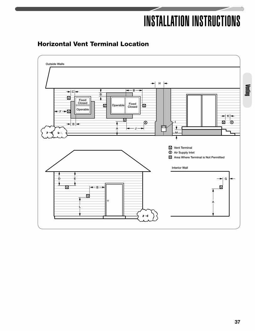
INSTALLATION INSTRUCTIONSHorizontal Vent Terminal Location
Outside Walls
FixedClosed
FixedClosed
OperableOperable
V
V
V
V
V
VX X
V
V
Interior Wall
Vent Terminal
Air Supply Inlet
Area Where Terminal is Not Permitted
B
B
A J
I
B
MM
F
C
K
H
V
V
D E
B
L
G
A
X
38
INSTALLATION INSTRUCTIONSVe
nting
Venting for Direct-Vent Water Heater (cont.)
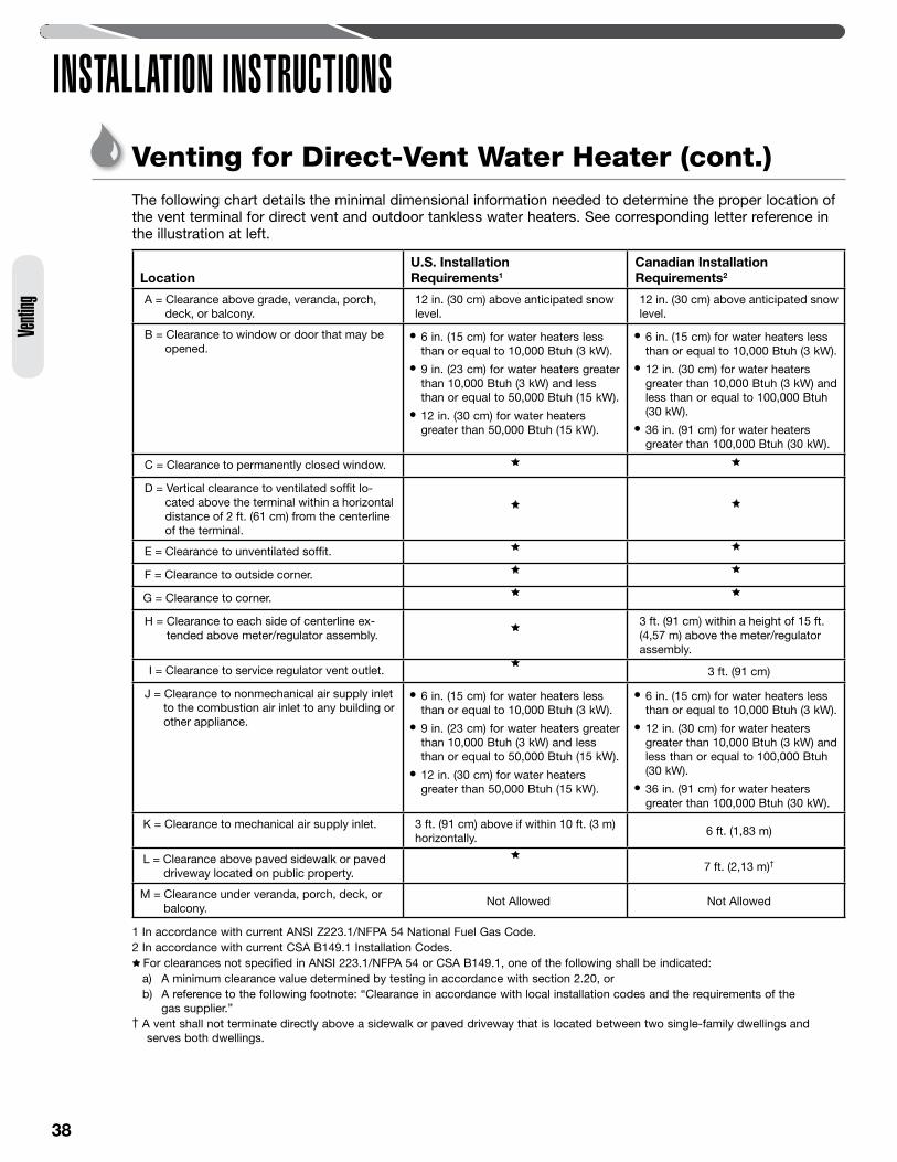
LocationU.S. Installation Requirements1
Canadian Installation Requirements2
A = Clearance above grade, veranda, porch, deck, or balcony.
12 in. (30 cm) above anticipated snow level.
12 in. (30 cm) above anticipated snow level.
B = Clearance to window or door that may be opened.
• 6 in. (15 cm) for water heaters less than or equal to 10,000 Btuh (3 kW).
• 9 in. (23 cm) for water heaters greater than 10,000 Btuh (3 kW) and less than or equal to 50,000 Btuh (15 kW).
• 12 in. (30 cm) for water heaters greater than 50,000 Btuh (15 kW).
• 6 in. (15 cm) for water heaters less than or equal to 10,000 Btuh (3 kW).
• 12 in. (30 cm) for water heaters greater than 10,000 Btuh (3 kW) and less than or equal to 100,000 Btuh (30 kW).
• 36 in. (91 cm) for water heaters greater than 100,000 Btuh (30 kW).
C = Clearance to permanently closed window.
D = Vertical clearance to ventilated soffit lo-cated above the terminal within a horizontal distance of 2 ft. (61 cm) from the centerline of the terminal.
E = Clearance to unventilated soffit.
F = Clearance to outside corner.
G = Clearance to corner.
H = Clearance to each side of centerline ex-tended above meter/regulator assembly.
3 ft. (91 cm) within a height of 15 ft. (4,57 m) above the meter/regulator assembly.
I = Clearance to service regulator vent outlet. 3 ft. (91 cm)
J = Clearance to nonmechanical air supply inlet to the combustion air inlet to any building or other appliance.
• 6 in. (15 cm) for water heaters less than or equal to 10,000 Btuh (3 kW).
• 9 in. (23 cm) for water heaters greater than 10,000 Btuh (3 kW) and less than or equal to 50,000 Btuh (15 kW).
• 12 in. (30 cm) for water heaters greater than 50,000 Btuh (15 kW).
• 6 in. (15 cm) for water heaters less than or equal to 10,000 Btuh (3 kW).
• 12 in. (30 cm) for water heaters greater than 10,000 Btuh (3 kW) and less than or equal to 100,000 Btuh (30 kW).
• 36 in. (91 cm) for water heaters greater than 100,000 Btuh (30 kW).
K = Clearance to mechanical air supply inlet. 3 ft. (91 cm) above if within 10 ft. (3 m) horizontally.
6 ft. (1,83 m)
L = Clearance above paved sidewalk or paved driveway located on public property. 7 ft. (2,13 m)†
M = Clearance under veranda, porch, deck, or balcony.
Not Allowed Not Allowed
1 In accordance with current ANSI Z223.1/NFPA 54 National Fuel Gas Code.2 In accordance with current CSA B149.1 Installation Codes.
For clearances not specified in ANSI 223.1/NFPA 54 or CSA B149.1, one of the following shall be indicated:a) A minimum clearance value determined by testing in accordance with section 2.20, orb) A reference to the following footnote: “Clearance in accordance with local installation codes and the requirements of the
gas supplier.Ӡ A vent shall not terminate directly above a sidewalk or paved driveway that is located between two single-family dwellings and
serves both dwellings.
The following chart details the minimal dimensional information needed to determine the proper location of the vent terminal for direct vent and outdoor tankless water heaters. See corresponding letter reference in the illustration at left.
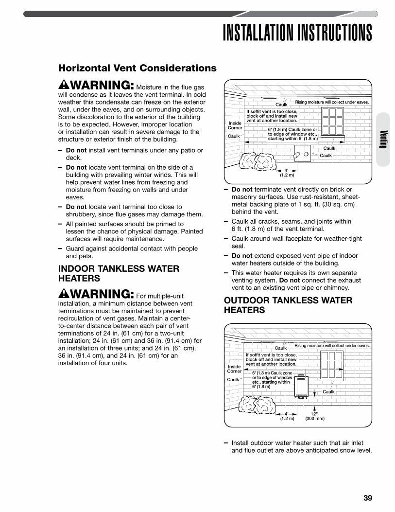
39
INSTALLATION INSTRUCTIONSVenting
Horizontal Vent Considerations
WARNING: Moisture in the flue gas will condense as it leaves the vent terminal. In cold weather this condensate can freeze on the exterior wall, under the eaves, and on surrounding objects. Some discoloration to the exterior of the building is to be expected. However, improper location or installation can result in severe damage to the structure or exterior finish of the building.
– Do not install vent terminals under any patio or deck.
– Do not locate vent terminal on the side of a building with prevailing winter winds. This will help prevent water lines from freezing and moisture from freezing on walls and under eaves.
– Do not locate vent terminal too close to shrubbery, since flue gases may damage them.
– All painted surfaces should be primed to lessen the chance of physical damage. Painted surfaces will require maintenance.
– Guard against accidental contact with people and pets.
INDOOR TANkLESS WATER HEATERS
WARNING: For multiple-unit installation, a minimum distance between vent terminations must be maintained to prevent recirculation of vent gases. Maintain a center-to-center distance between each pair of vent terminations of 24 in. (61 cm) for a two-unit installation; 24 in. (61 cm) and 36 in. (91.4 cm) for an installation of three units; and 24 in. (61 cm), 36 in. (91.4 cm), and 24 in. (61 cm) for an installation of four units.
– Do not terminate vent directly on brick or masonry surfaces. Use rust-resistant, sheet-metal backing plate of 1 sq. ft. (30 sq. cm) behind the vent.
– Caulk all cracks, seams, and joints within 6 ft. (1.8 m) of the vent terminal.
– Caulk around wall faceplate for weather-tight seal.
– Do not extend exposed vent pipe of indoor water heaters outside of the building.
– This water heater requires its own separate venting system. Do not connect the exhaust vent to an existing vent pipe or chimney.
OUTDOOR TANkLESS WATER HEATERS
– Install outdoor water heater such that air inlet and flue outlet are above anticipated snow level.
Rising moisture will collect under eaves.
InsideCorner
Caulk
Caulk
Caulk
Caulk
If sof�t vent is too close,block off and install newvent at another location.
6' (1.8 m) Caulk zone or to edge of window etc., starting within 6' (1.8 m)
4' (1.2 m)
Rising moisture will collect under eaves.
InsideCorner
Caulk
Caulk
Caulk
If sof�t vent is too close,block off and install newvent at another location.
6' (1.8 m) Caulk zoneor to edge of windowetc., starting within 6' (1.8 m)
4' (1.2 m)
12" (300 mm)
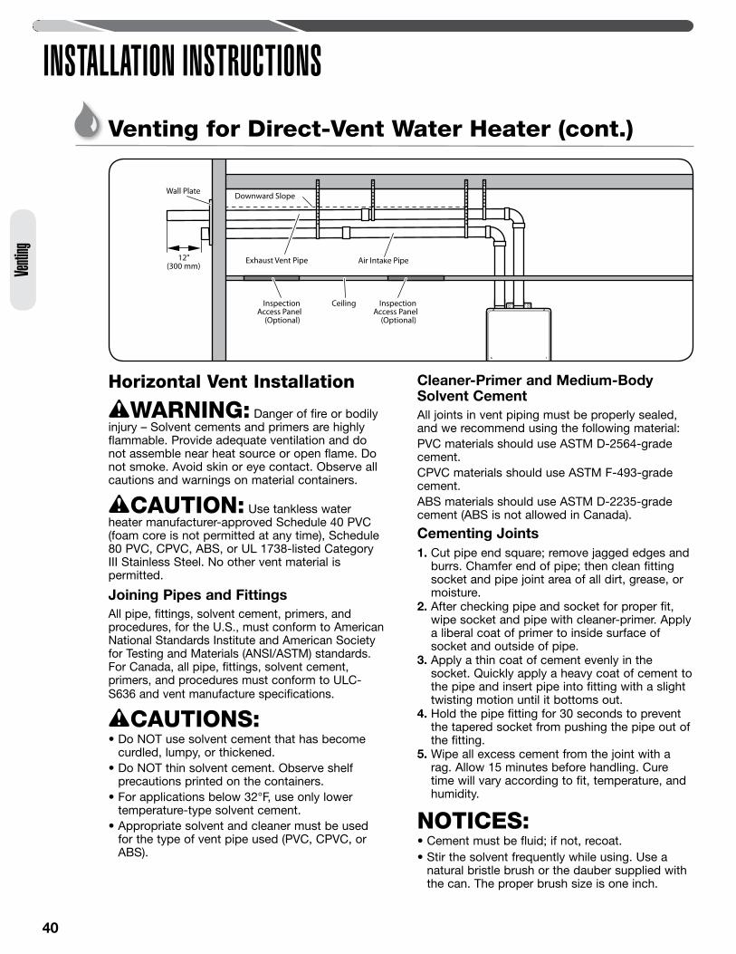
40
Venti
ng
INSTALLATION INSTRUCTIONSVenting for Direct-Vent Water Heater (cont.)
Exhaust Vent Pipe Air Intake Pipe
Wall Plate
InspectionAccess Panel
(Optional)
InspectionAccess Panel
(Optional)
Ceiling
Downward Slope
12"(300 mm)
Horizontal Vent Installation
WARNING: Danger of fire or bodily injury – Solvent cements and primers are highly flammable. Provide adequate ventilation and do not assemble near heat source or open flame. Do not smoke. Avoid skin or eye contact. Observe all cautions and warnings on material containers.
CAUTION: Use tankless water heater manufacturer-approved Schedule 40 PVC (foam core is not permitted at any time), Schedule 80 PVC, CPVC, ABS, or UL 1738-listed Category III Stainless Steel. No other vent material is permitted.
Joining Pipes and FittingsAll pipe, fittings, solvent cement, primers, and procedures, for the U.S., must conform to American National Standards Institute and American Society for Testing and Materials (ANSI/ASTM) standards. For Canada, all pipe, fittings, solvent cement, primers, and procedures must conform to ULC-S636 and vent manufacture specifications.
CAUTIONS: • Do NOT use solvent cement that has become
curdled, lumpy, or thickened.• Do NOT thin solvent cement. Observe shelf
precautions printed on the containers. • For applications below 32°F, use only lower
temperature-type solvent cement.• Appropriate solvent and cleaner must be used
for the type of vent pipe used (PVC, CPVC, or ABS).
Cleaner-Primer and Medium-Body Solvent CementAll joints in vent piping must be properly sealed, and we recommend using the following material:PVC materials should use ASTM D-2564-grade cement.CPVC materials should use ASTM F-493-grade cement.ABS materials should use ASTM D-2235-grade cement (ABS is not allowed in Canada).
Cementing Joints1. Cut pipe end square; remove jagged edges and
burrs. Chamfer end of pipe; then clean fitting socket and pipe joint area of all dirt, grease, or moisture.
2. After checking pipe and socket for proper fit, wipe socket and pipe with cleaner-primer. Apply a liberal coat of primer to inside surface of socket and outside of pipe.
3. Apply a thin coat of cement evenly in the socket. Quickly apply a heavy coat of cement to the pipe and insert pipe into fitting with a slight twisting motion until it bottoms out.
4. Hold the pipe fitting for 30 seconds to prevent the tapered socket from pushing the pipe out of the fitting.
5. Wipe all excess cement from the joint with a rag. Allow 15 minutes before handling. Cure time will vary according to fit, temperature, and humidity.
NOTICES: • Cement must be fluid; if not, recoat.• Stir the solvent frequently while using. Use a
natural bristle brush or the dauber supplied with the can. The proper brush size is one inch.
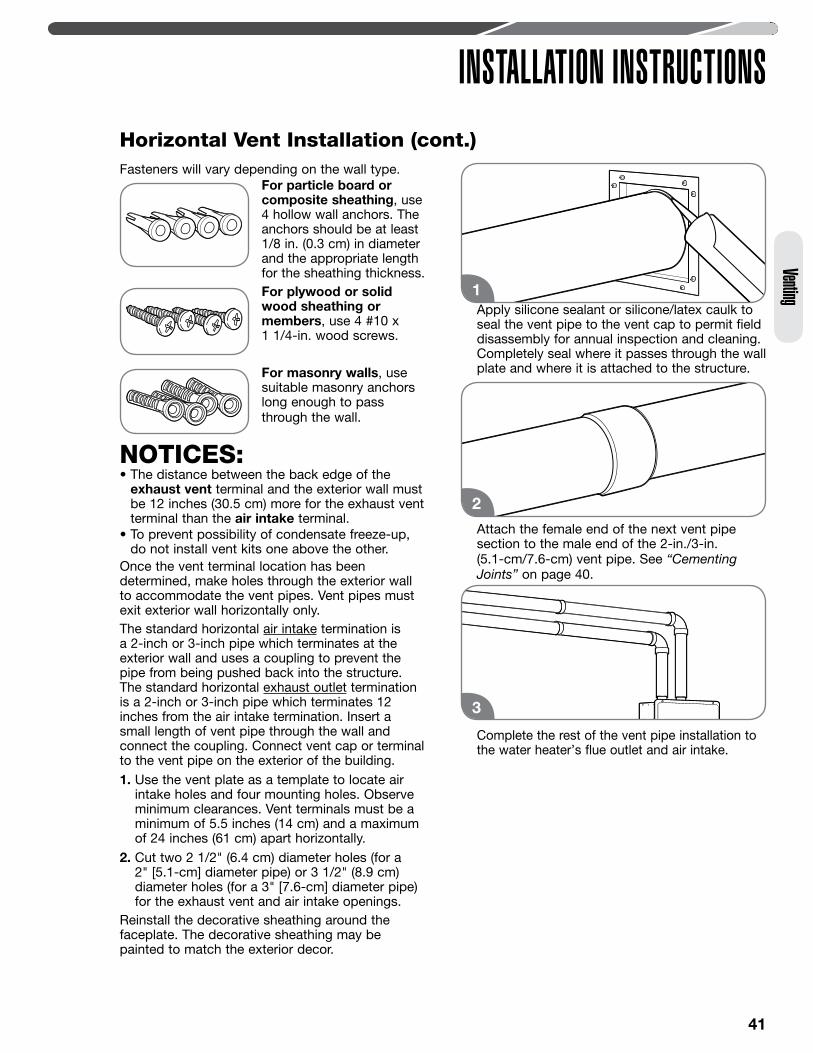
41
Venting
INSTALLATION INSTRUCTIONSHorizontal Vent Installation (cont.)Fasteners will vary depending on the wall type.
For particle board or composite sheathing, use 4 hollow wall anchors. The anchors should be at least 1/8 in. (0.3 cm) in diameter and the appropriate length for the sheathing thickness.
For plywood or solid wood sheathing or members, use 4 #10 x 1 1/4-in. wood screws.
For masonry walls, use suitable masonry anchors long enough to pass through the wall.
NOTICES: • The distance between the back edge of the
exhaust vent terminal and the exterior wall must be 12 inches (30.5 cm) more for the exhaust vent terminal than the air intake terminal.
• To prevent possibility of condensate freeze-up, do not install vent kits one above the other.
Once the vent terminal location has been determined, make holes through the exterior wall to accommodate the vent pipes. Vent pipes must exit exterior wall horizontally only.The standard horizontal air intake termination is a 2-inch or 3-inch pipe which terminates at the exterior wall and uses a coupling to prevent the pipe from being pushed back into the structure. The standard horizontal exhaust outlet termination is a 2-inch or 3-inch pipe which terminates 12 inches from the air intake termination. Insert a small length of vent pipe through the wall and connect the coupling. Connect vent cap or terminal to the vent pipe on the exterior of the building. 1. Use the vent plate as a template to locate air
intake holes and four mounting holes. Observe minimum clearances. Vent terminals must be a minimum of 5.5 inches (14 cm) and a maximum of 24 inches (61 cm) apart horizontally.
2. Cut two 2 1/2" (6.4 cm) diameter holes (for a 2" [5.1-cm] diameter pipe) or 3 1/2" (8.9 cm) diameter holes (for a 3" [7.6-cm] diameter pipe) for the exhaust vent and air intake openings.
Reinstall the decorative sheathing around the faceplate. The decorative sheathing may be painted to match the exterior decor.
Apply silicone sealant or silicone/latex caulk to seal the vent pipe to the vent cap to permit field disassembly for annual inspection and cleaning. Completely seal where it passes through the wall plate and where it is attached to the structure.
Attach the female end of the next vent pipe section to the male end of the 2-in./3-in. (5.1-cm/7.6-cm) vent pipe. See “Cementing Joints” on page 40.
Complete the rest of the vent pipe installation to the water heater’s flue outlet and air intake.
1
3
2
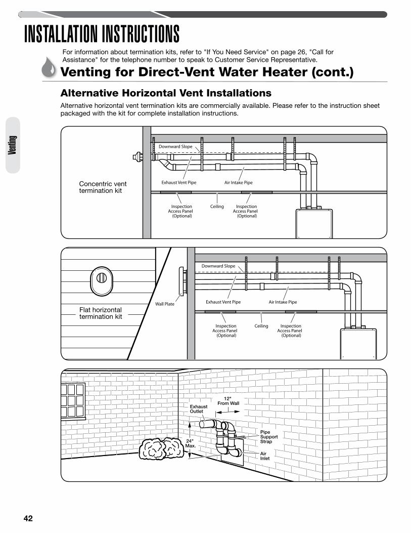
42
Venti
ng
INSTALLATION INSTRUCTIONSVenting for Direct-Vent Water Heater (cont.)
Alternative Horizontal Vent Installations
Exhaust Vent Pipe Air Intake Pipe
InspectionAccess Panel
(Optional)
InspectionAccess Panel
(Optional)
Ceiling
Downward Slope
Exhaust Vent Pipe Air Intake PipeWall Plate
InspectionAccess Panel
(Optional)
InspectionAccess Panel
(Optional)
Ceiling
Downward Slope
Alternative horizontal vent termination kits are commercially available. Please refer to the instruction sheet packaged with the kit for complete installation instructions.
AirInlet
ExhaustOutlet
PipeSupportStrap24"
Max.
12" From Wall
Concentric vent termination kit
Flat horizontal termination kit
For information about termination kits, refer to "If You Need Service" on page 26, "Call for Assistance" for the telephone number to speak to Customer Service Representative.
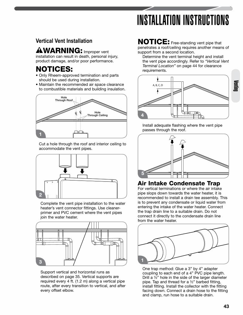
43
Venting
INSTALLATION INSTRUCTIONSVertical Vent Installation
WARNING: Improper vent installation can result in death, personal injury, product damage, and/or poor performance.
NOTICES: • Only Rheem-approved termination and parts
should be used during installation.• Maintain the recommended air space clearance
to combustible materials and building insulation.
Cut a hole through the roof and interior ceiling to accommodate the vent pipes.
Complete the vent pipe installation to the water heater’s vent connector fittings. Use cleaner-primer and PVC cement where the vent pipes join the water heater.
Support vertical and horizontal runs as described on page 35. Vertical supports are required every 4 ft. (1.2 m) along a vertical pipe route, after every transition to vertical, and after every offset elbow.
NOTICE: Free-standing vent pipe that penetrates a roof/ceiling requires another means of support from a second location. Determine the vent terminal height and install
the vent pipe accordingly. Refer to “Vertical Vent Terminal Location” on page 44 for clearance requirements.
Install adequate flashing where the vent pipe passes through the roof.
Air Intake Condensate TrapFor vertical terminations or where the air intake pipe slops down towards the water heater, it is recommended to install a drain tee assembly. This is to prevent any condensate or liquid water from entering the intake of the water heater. Connect the trap drain line to a suitable drain. Do not connect it directly to the condensate drain line from the water heater.
One trap method: Glue a 3” by 4” adapter coupling to each end of a 4” PVC pipe length. Drill a ½” hole in the side of the larger diameter pipe. Tap and thread for a ½” barbed fitting, install fitting. Install the collector with the fitting facing down. Connect a drain hose to the fitting and clamp, run hose to a suitable drain.
HoleThrough Roof
CL HoleThrough Ceiling
CL
1
2
A, B, C, D
4
5
3 1
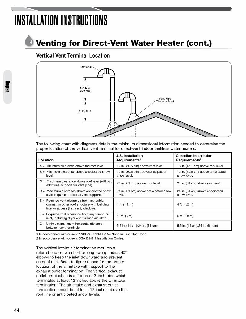
44
Vertical Vent Terminal Location
A, B, C, D
12" Min.(300 mm)
Vent PipeThrough Roof
Optional
The following chart with diagrams details the minimum dimensional information needed to determine the proper location of the vertical vent terminal for direct-vent indoor tankless water heaters:
LocationU.S. Installation Requirements1
Canadian Installation Requirements2
A = Minimum clearance above the roof level. 12 in. (30.5 cm) above roof level. 18 in. (45.7 cm) above roof level.
B = Minimum clearance above anticipated snow level.
12 in. (30.5 cm) above anticipated snow level.
12 in. (30.5 cm) above anticipated snow level.
C = Maximum clearance above roof level (without additional support for vent pipe).
24 in. (61 cm) above roof level. 24 in. (61 cm) above roof level.
D = Maximum clearance above anticipated snow level (requires additional vent support).
24 in. (61 cm) above anticipated snow level.
24 in. (61 cm) above anticipated snow level.
E = Required vent clearance from any gable, dormer, or other roof structure with building interior access (i.e., vent, window).
4 ft. (1.2 m) 4 ft. (1.2 m)
F = Required vent clearance from any forced air inlet, including dryer and furnace air inlets.
10 ft. (3 m) 6 ft. (1.8 m)
G = Minimum/maximum horizontal distance between vent terminals
5.5 in. (14 cm)/24 in. (61 cm) 5.5 in. (14 cm)/24 in. (61 cm)
1 In accordance with current ANSI Z223.1/NFPA 54 National Fuel Gas Code.2 In accordance with current CSA B149.1 Installation Codes.
The vertical intake air termination requires a return bend or two short or long sweep radius 90° elbows to keep the inlet downward and prevent entry of rain. Refer to figure above for the proper location of the air intake with respect to the exhaust outlet termination. The vertical exhaust outlet termination is a 2-inch or 3-inch pipe which terminates at least 12 inches above the air intake termination. The air intake and exhaust outlet terminations must be at least 12 inches above the roof line or anticipated snow levels.
Venti
ng
INSTALLATION INSTRUCTIONSVenting for Direct-Vent Water Heater (cont.)
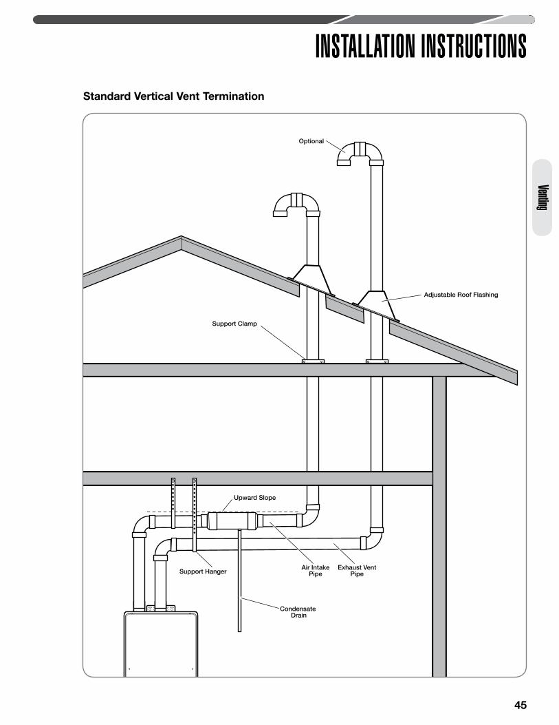
45
Venting
INSTALLATION INSTRUCTIONS
Adjustable Roof Flashing
Support Clamp
Upward Slope
Support HangerAir Intake
PipeExhaust Vent
Pipe
Condensate Drain
Optional
Standard Vertical Vent Termination
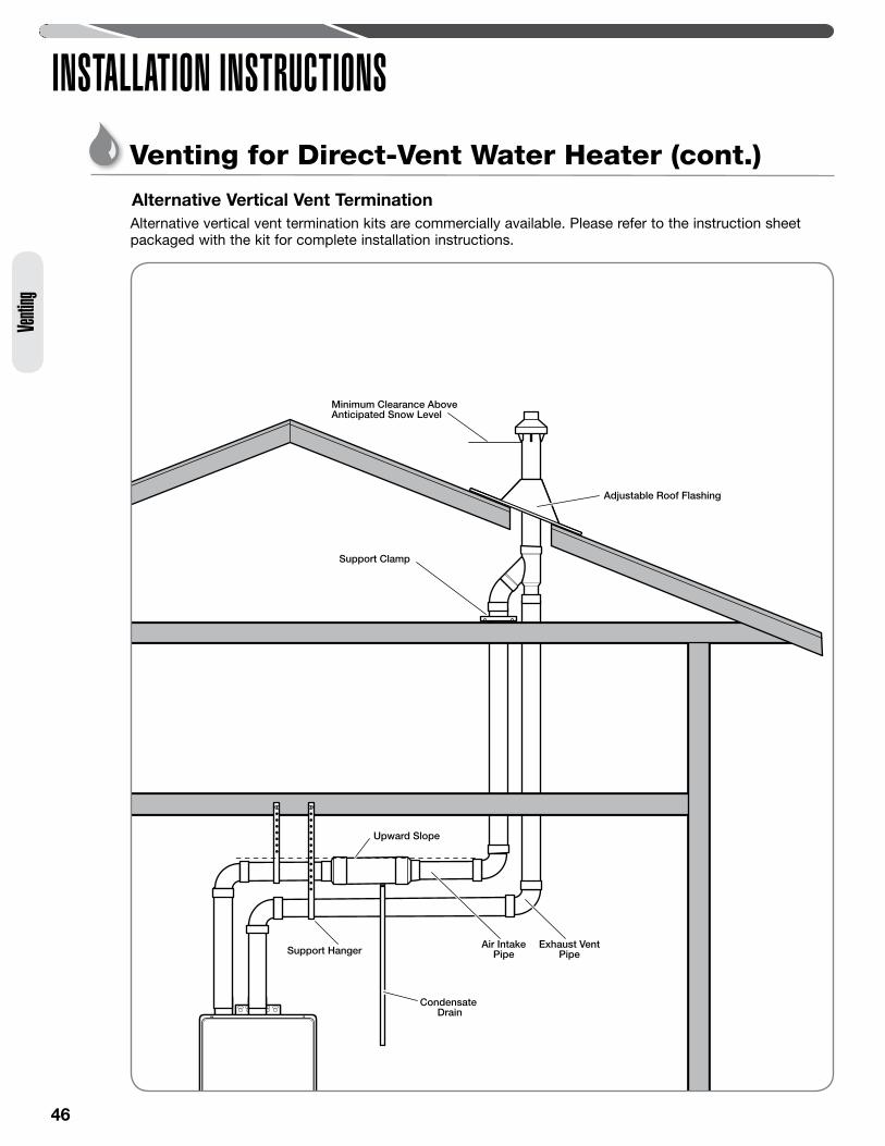
46
Support Hanger
Adjustable Roof Flashing
Support Clamp
Upward Slope
Air IntakePipe
Exhaust VentPipe
Minimum Clearance AboveAnticipated Snow Level
Condensate Drain
Alternative Vertical Vent Termination
INSTALLATION INSTRUCTIONSVenting for Direct-Vent Water Heater (cont.)
Venti
ng
Alternative vertical vent termination kits are commercially available. Please refer to the instruction sheet packaged with the kit for complete installation instructions.

47
INSTALLATION INSTRUCTIONS
CAUTION: This water heater MUST ONLY be used with the following water supply conditions to prevent product damage and operation failure.
• Clean, potable water free of corrosive chemicals, sand, dirt, or other contaminates.
• Inlet water temperatures above 32°F (0°C), but not exceeding 120°F (49°C).
• DO NOT reverse the HOT and COLD water connections.
• DO NOT connect this water heater to water lines previously used for space heating. All water piping and components shall be suitable for potable water.
• With recommended water quality (see chart).
Thermal ExpansionA thermal expansion tank will be required if the water heater is installed in a recirculation system. This prevents damage to the heater, related piping, and the relief valve.
NOTICE: Replacing the relief valve will not correct the problem!
The expansion tank is designed with a built-in air cushion that compresses as the system pressure increases. This relieves the over-pressure condition and eliminates the repeat operation of the relief valve.
For other approved methods of thermal expansion, contact an installing contractor, water supplier, or plumbing inspector.
Water Supply ConnectionsCAUTION: IMPORTANT—Do
not apply heat to the HOT or COLD water connections. If sweat connections are used, sweat tubing to the adapter before fitting the adapter to the water connections on the water heater. Any heat applied to the water supply fittings will permanently damage the internal components of the water heater.
NOTICE: In cold environments, ice can accumulate in the water heater’s connectors. Plug in the water heater power cord for approximately 10 minutes before making these connections. This will melt any ice buildup.
Plumbing should be carried out by a qualified plumbing contractor in accordance with local codes.
Only use approved plumbing materials.
The minimum diameter of all water pipes should be 3/4 in. (1.9 cm).
To conserve energy and to prevent freezing, insulate both COLD and HOT water supply lines. Do not insulate the drain line or pressure-relief valve.
Chart for Recommended Water Quality Levels
pHTDS (Total
Dissolved Solids)Free Carbon Dioxide (CO2)
Total Hardness Aluminum Chlorides Copper Iron Manganese Zinc
6.5–8.5 Up to 500 mg/L Up to 15 mg/LUp to
200 mg/LUp to
0.2 mg/LUp to
200 mg/LUp to
1.0 mg/LUp to
0.3 mg/LUp to
0.05 mg/LUp to
1.0 mg/L
Water Supply
Plumbing
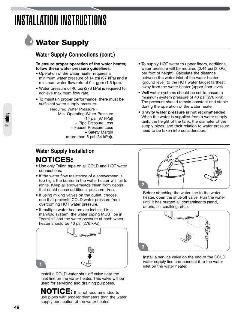
48
INSTALLATION INSTRUCTIONSWater Supply
Plumb
ing
Water Supply InstallationNOTICES: • Use only Teflon tape on all COLD and HOT water
connections.• If the water flow resistance of a showerhead is
too high, the burner in the water heater will fail to ignite. Keep all showerheads clean from debris that could cause additional pressure drop.
• If using mixing valves on the outlet, choose one that prevents COLD water pressure from overcoming HOT water pressure.
• If multiple water heaters are installed in a manifold system, the water piping MUST be in “parallel” and the water pressure at each water heater should be 40 psi (276 kPa).
Install a COLD water shut-off valve near the inlet line on the water heater. This valve will be used for servicing and draining purposes.
NOTICE: It is not recommended to use pipes with smaller diameters than the water supply connection of the water heater.
Before attaching the water line to the water heater, open the shut-off valve. Run the water until it has purged all contaminants (sand, debris, air, caulking, etc.).
Install a service valve on the end of the COLD water supply line and connect it to the water inlet on the water heater.
To ensure proper operation of the water heater, follow these water pressure guidelines.• Operation of the water heater requires a
minimum water pressure of 14 psi (97 kPa) and a minimum water flow rate of 0.4 gpm (1.5 lpm).
• Water pressure of 40 psi (276 kPa) is required to achieve maximum flow rate.
• To maintain proper performance, there must be sufficient water supply pressure.
Required Water Pressure = Min. Operating Water Pressure
(14 psi [97 kPa]) + Pipe Pressure Loss
+ Faucet Pressure Loss + Safety Margin
(more than 5 psi [34 kPa]).
• To supply HOT water to upper floors, additional water pressure will be required (0.44 psi [3 kPa] per foot of height). Calculate the distance between the water inlet of the water heater (ground level) to the HOT water faucet farthest away from the water heater (upper floor level).
• Well water systems should be set to ensure a minimum system pressure of 40 psi (276 kPa). The pressure should remain constant and stable during the operation of the water heater.
• Gravity water pressure is not recommended. When the water is supplied from a water supply tank, the height of the tank, the diameter of the supply pipes, and their relation to water pressure need to be taken into consideration.
1
Water Supply Connections (cont.)
2
3
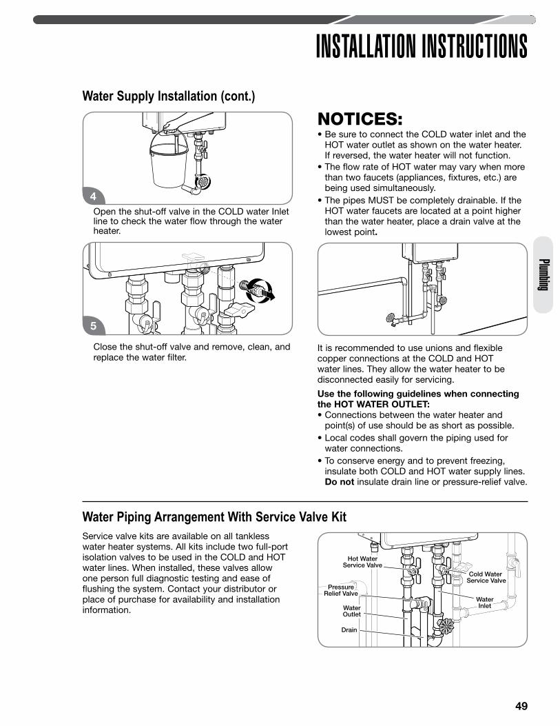
49
INSTALLATION INSTRUCTIONSPlumbing
Open the shut-off valve in the COLD water Inlet line to check the water flow through the water heater.
Close the shut-off valve and remove, clean, and replace the water filter.
NOTICES: • Be sure to connect the COLD water inlet and the
HOT water outlet as shown on the water heater. If reversed, the water heater will not function.
• The flow rate of HOT water may vary when more than two faucets (appliances, fixtures, etc.) are being used simultaneously.
• The pipes MUST be completely drainable. If the HOT water faucets are located at a point higher than the water heater, place a drain valve at the lowest point.
It is recommended to use unions and flexible copper connections at the COLD and HOT water lines. They allow the water heater to be disconnected easily for servicing.
Use the following guidelines when connecting the HOT WATER OUTLET:• Connections between the water heater and
point(s) of use should be as short as possible.• Local codes shall govern the piping used for
water connections. • To conserve energy and to prevent freezing,
insulate both COLD and HOT water supply lines. Do not insulate drain line or pressure-relief valve.
5
4
PressureRelief Valve
PressureRelief Valve
Cold Water Service ValveCold Water
Service Valve
WaterInlet
WaterInletWater
OutletWaterOutlet
Hot WaterService Valve
Hot WaterService Valve
DrainDrain
Water Piping Arrangement With Service Valve KitService valve kits are available on all tankless water heater systems. All kits include two full-port isolation valves to be used in the COLD and HOT water lines. When installed, these valves allow one person full diagnostic testing and ease of flushing the system. Contact your distributor or place of purchase for availability and installation information.
Water Supply Installation (cont.)
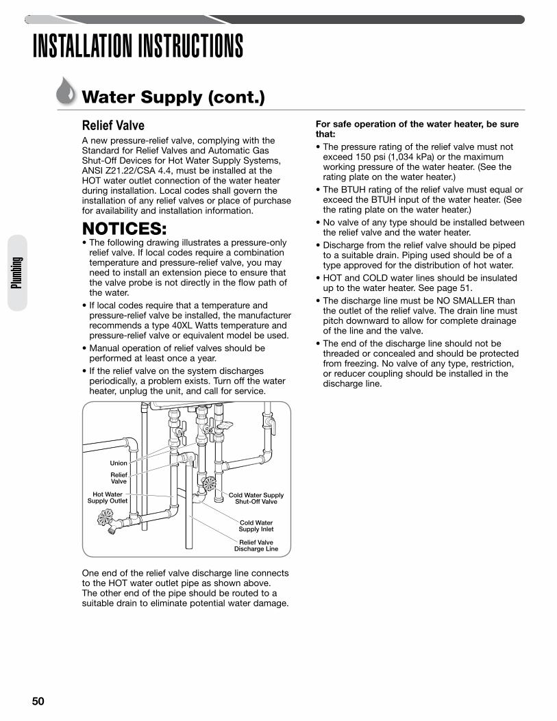
50
INSTALLATION INSTRUCTIONSPlu
mbing
Water Supply (cont.)
Relief ValveA new pressure-relief valve, complying with the Standard for Relief Valves and Automatic Gas Shut-Off Devices for Hot Water Supply Systems, ANSI Z21.22/CSA 4.4, must be installed at the HOT water outlet connection of the water heater during installation. Local codes shall govern the installation of any relief valves or place of purchase for availability and installation information.
NOTICES: • The following drawing illustrates a pressure-only
relief valve. If local codes require a combination temperature and pressure-relief valve, you may need to install an extension piece to ensure that the valve probe is not directly in the flow path of the water.
• If local codes require that a temperature and pressure-relief valve be installed, the manufacturer recommends a type 40XL Watts temperature and pressure-relief valve or equivalent model be used.
• Manual operation of relief valves should be performed at least once a year.
• If the relief valve on the system discharges periodically, a problem exists. Turn off the water heater, unplug the unit, and call for service.
One end of the relief valve discharge line connects to the HOT water outlet pipe as shown above. The other end of the pipe should be routed to a suitable drain to eliminate potential water damage.
For safe operation of the water heater, be sure that:• The pressure rating of the relief valve must not
exceed 150 psi (1,034 kPa) or the maximum working pressure of the water heater. (See the rating plate on the water heater.)
• The BTUH rating of the relief valve must equal or exceed the BTUH input of the water heater. (See the rating plate on the water heater.)
• No valve of any type should be installed between the relief valve and the water heater.
• Discharge from the relief valve should be piped to a suitable drain. Piping used should be of a type approved for the distribution of hot water.
• HOT and COLD water lines should be insulated up to the water heater. See page 51.
• The discharge line must be NO SMALLER than the outlet of the relief valve. The drain line must pitch downward to allow for complete drainage of the line and the valve.
• The end of the discharge line should not be threaded or concealed and should be protected from freezing. No valve of any type, restriction, or reducer coupling should be installed in the discharge line.
ReliefValve
UnionUnion
Cold Water SupplyShut-Off Valve
Cold WaterSupply Inlet
Hot WaterSupply Outlet
Relief ValveDischarge Line
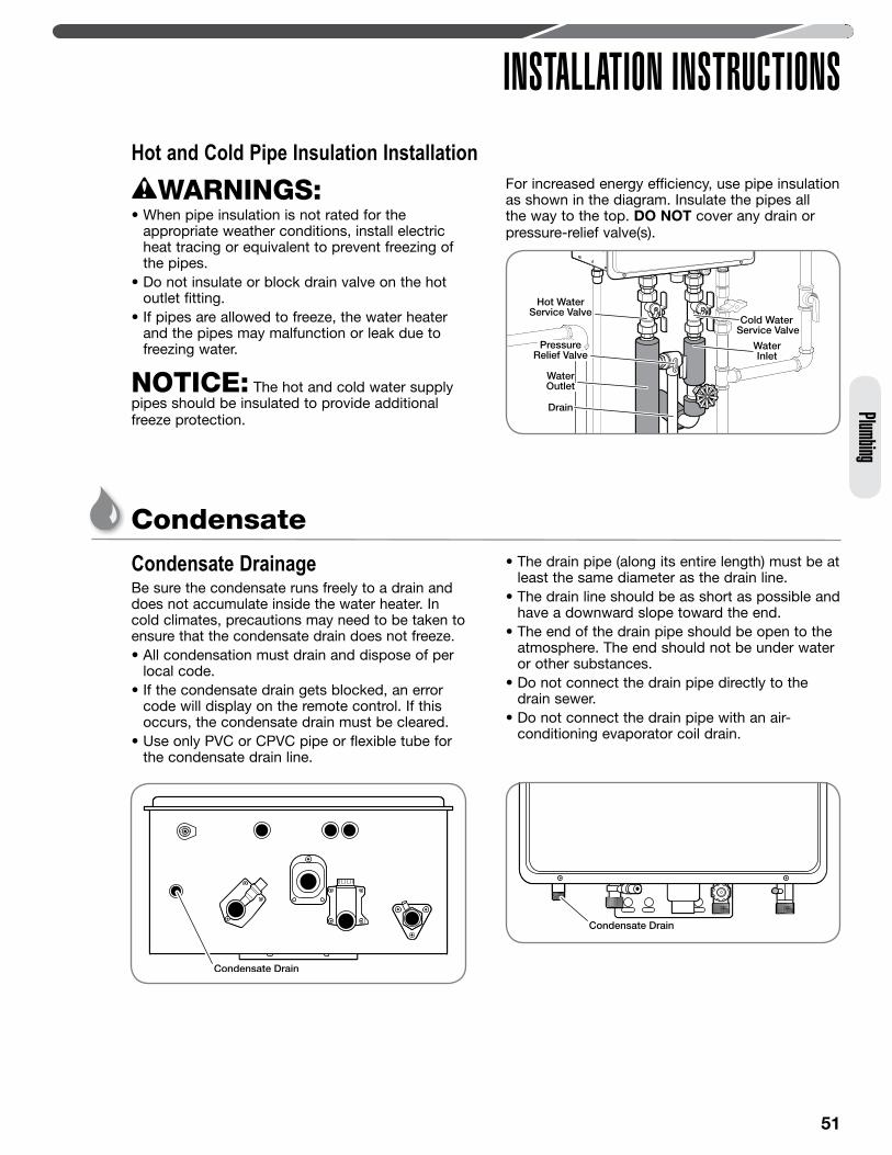
51
INSTALLATION INSTRUCTIONSPlumbing
WARNINGS: • When pipe insulation is not rated for the
appropriate weather conditions, install electric heat tracing or equivalent to prevent freezing of the pipes.
• Do not insulate or block drain valve on the hot outlet fitting.
• If pipes are allowed to freeze, the water heater and the pipes may malfunction or leak due to freezing water.
NOTICE: The hot and cold water supply pipes should be insulated to provide additional freeze protection.
For increased energy efficiency, use pipe insulation as shown in the diagram. Insulate the pipes all the way to the top. DO NOT cover any drain or pressure-relief valve(s).
Hot and Cold Pipe Insulation Installation
Cold Water Service Valve
Hot WaterService Valve
PressureRelief Valve
PressureRelief Valve
Water OutletWaterOutlet
Water Inlet
WaterInlet
DrainDrain
Condensate DrainageBe sure the condensate runs freely to a drain and does not accumulate inside the water heater. In cold climates, precautions may need to be taken to ensure that the condensate drain does not freeze. • All condensation must drain and dispose of per
local code. • If the condensate drain gets blocked, an error
code will display on the remote control. If this occurs, the condensate drain must be cleared.
• Use only PVC or CPVC pipe or flexible tube for the condensate drain line.
• The drain pipe (along its entire length) must be at least the same diameter as the drain line.
• The drain line should be as short as possible and have a downward slope toward the end.
• The end of the drain pipe should be open to the atmosphere. The end should not be under water or other substances.
• Do not connect the drain pipe directly to the drain sewer.
• Do not connect the drain pipe with an air-conditioning evaporator coil drain.
Condensate
Condensate Drain
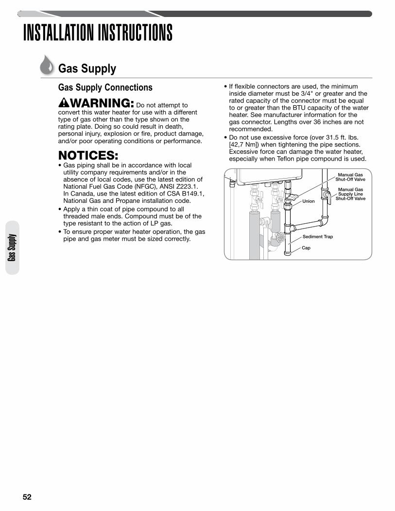
52
INSTALLATION INSTRUCTIONS
Gas Supply ConnectionsWARNING: Do not attempt to
convert this water heater for use with a different type of gas other than the type shown on the rating plate. Doing so could result in death, personal injury, explosion or fire, product damage, and/or poor operating conditions or performance.
NOTICES: • Gas piping shall be in accordance with local
utility company requirements and/or in the absence of local codes, use the latest edition of National Fuel Gas Code (NFGC), ANSI Z223.1. In Canada, use the latest edition of CSA B149.1, National Gas and Propane installation code.
• Apply a thin coat of pipe compound to all threaded male ends. Compound must be of the type resistant to the action of LP gas.
• To ensure proper water heater operation, the gas pipe and gas meter must be sized correctly.
• If flexible connectors are used, the minimum inside diameter must be 3/4" or greater and the rated capacity of the connector must be equal to or greater than the BTU capacity of the water heater. See manufacturer information for the gas connector. Lengths over 36 inches are not recommended.
• Do not use excessive force (over 31.5 ft. lbs. [42,7 Nm]) when tightening the pipe sections. Excessive force can damage the water heater, especially when Teflon pipe compound is used.
Gas Supply
Union
Manual GasSupply Line
Shut-Off Valve
Cap
Sediment Trap
Manual GasShut-Off Valve
Gas S
upply
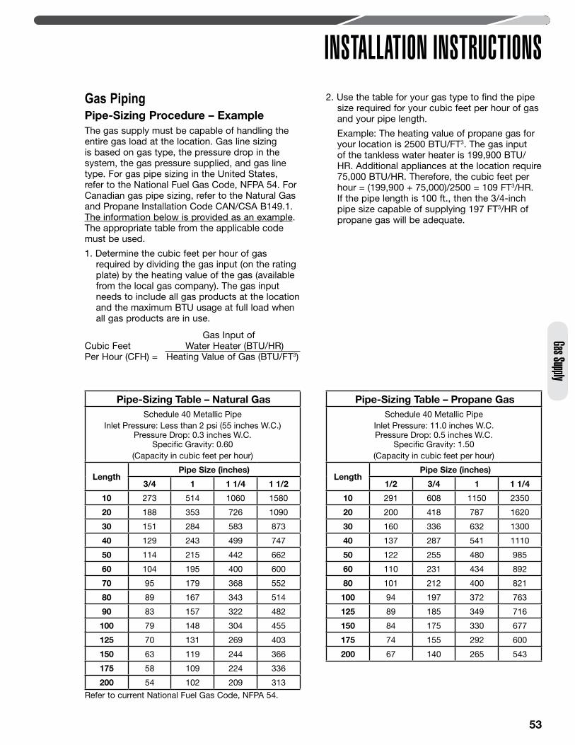
53
INSTALLATION INSTRUCTIONSGas Supply
Gas PipingPipe-Sizing Procedure – ExampleThe gas supply must be capable of handling the entire gas load at the location. Gas line sizing is based on gas type, the pressure drop in the system, the gas pressure supplied, and gas line type. For gas pipe sizing in the United States, refer to the National Fuel Gas Code, NFPA 54. For Canadian gas pipe sizing, refer to the Natural Gas and Propane Installation Code CAN/CSA B149.1. The information below is provided as an example. The appropriate table from the applicable code must be used.
1. Determine the cubic feet per hour of gas required by dividing the gas input (on the rating plate) by the heating value of the gas (available from the local gas company). The gas input needs to include all gas products at the location and the maximum BTU usage at full load when all gas products are in use.
2. Use the table for your gas type to find the pipe size required for your cubic feet per hour of gas and your pipe length.
Example: The heating value of propane gas for your location is 2500 BTU/FT3. The gas input of the tankless water heater is 199,900 BTU/HR. Additional appliances at the location require 75,000 BTU/HR. Therefore, the cubic feet per hour = (199,900 + 75,000)/2500 = 109 FT3/HR. If the pipe length is 100 ft., then the 3/4-inch pipe size capable of supplying 197 FT3/HR of propane gas will be adequate.
Gas Input of Cubic Feet Water Heater (BTU/HR) Per Hour (CFH) = Heating Value of Gas (BTU/FT3)
Pipe-Sizing Table – Natural GasSchedule 40 Metallic Pipe
Inlet Pressure: Less than 2 psi (55 inches W.C.)Pressure Drop: 0.3 inches W.C.
Specific Gravity: 0.60 (Capacity in cubic feet per hour)
LengthPipe Size (inches)
3/4 1 1 1/4 1 1/2
10 273 514 1060 1580
20 188 353 726 1090
30 151 284 583 873
40 129 243 499 747
50 114 215 442 662
60 104 195 400 600
70 95 179 368 552
80 89 167 343 514
90 83 157 322 482
100 79 148 304 455
125 70 131 269 403
150 63 119 244 366
175 58 109 224 336
200 54 102 209 313
Pipe-Sizing Table – Propane GasSchedule 40 Metallic Pipe
Inlet Pressure: 11.0 inches W.C.Pressure Drop: 0.5 inches W.C.
Specific Gravity: 1.50 (Capacity in cubic feet per hour)
LengthPipe Size (inches)
1/2 3/4 1 1 1/4
10 291 608 1150 2350
20 200 418 787 1620
30 160 336 632 1300
40 137 287 541 1110
50 122 255 480 985
60 110 231 434 892
80 101 212 400 821
100 94 197 372 763
125 89 185 349 716
150 84 175 330 677
175 74 155 292 600
200 67 140 265 543
Refer to current National Fuel Gas Code, NFPA 54.
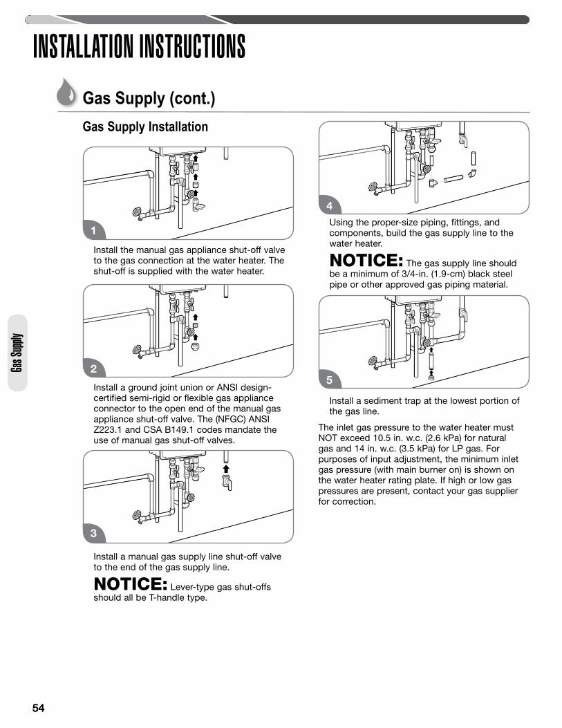
54
INSTALLATION INSTRUCTIONSGa
s Supp
ly
Gas Supply Installation
Install the manual gas appliance shut-off valve to the gas connection at the water heater. The shut-off is supplied with the water heater.
Install a ground joint union or ANSI design-certified semi-rigid or flexible gas appliance connector to the open end of the manual gas appliance shut-off valve. The (NFGC) ANSI Z223.1 and CSA B149.1 codes mandate the use of manual gas shut-off valves.
Install a manual gas supply line shut-off valve to the end of the gas supply line.
NOTICE: Lever-type gas shut-offs should all be T-handle type.
Using the proper-size piping, fittings, and components, build the gas supply line to the water heater.
NOTICE: The gas supply line should be a minimum of 3/4-in. (1.9-cm) black steel pipe or other approved gas piping material.
Install a sediment trap at the lowest portion of the gas line.
The inlet gas pressure to the water heater must NOT exceed 10.5 in. w.c. (2.6 kPa) for natural gas and 14 in. w.c. (3.5 kPa) for LP gas. For purposes of input adjustment, the minimum inlet gas pressure (with main burner on) is shown on the water heater rating plate. If high or low gas pressures are present, contact your gas supplier for correction.
1
2
4
3
5
Gas Supply (cont.)
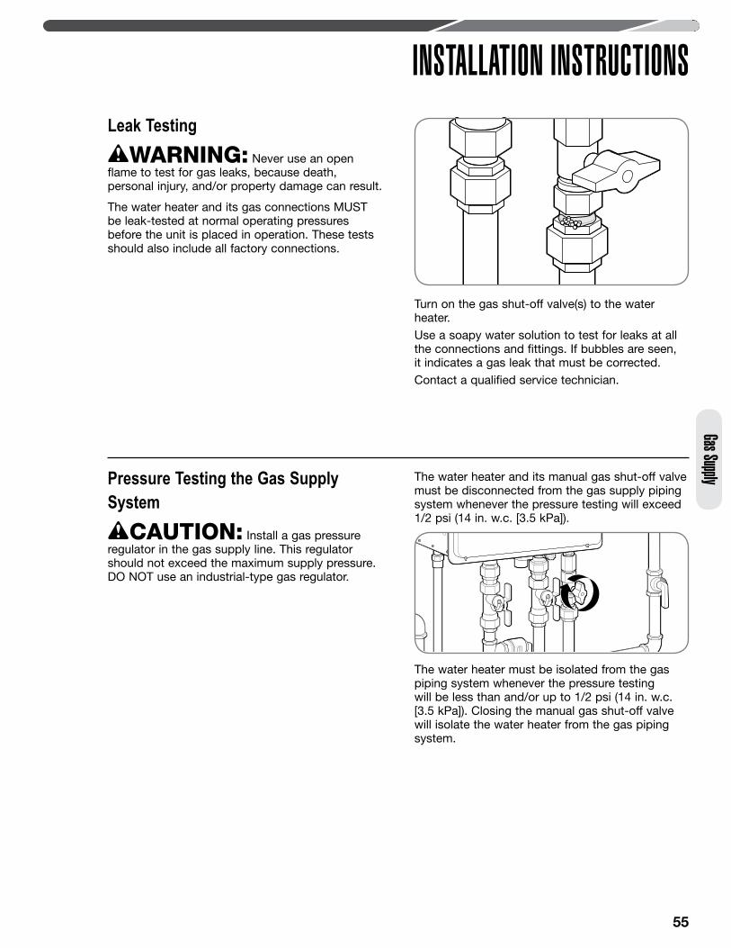
55
INSTALLATION INSTRUCTIONSGas Supply
Leak TestingWARNING: Never use an open
flame to test for gas leaks, because death, personal injury, and/or property damage can result.
The water heater and its gas connections MUST be leak-tested at normal operating pressures before the unit is placed in operation. These tests should also include all factory connections.
Turn on the gas shut-off valve(s) to the water heater.Use a soapy water solution to test for leaks at all the connections and fittings. If bubbles are seen, it indicates a gas leak that must be corrected.Contact a qualified service technician.
Pressure Testing the Gas Supply System
CAUTION: Install a gas pressure regulator in the gas supply line. This regulator should not exceed the maximum supply pressure. DO NOT use an industrial-type gas regulator.
The water heater and its manual gas shut-off valve must be disconnected from the gas supply piping system whenever the pressure testing will exceed 1/2 psi (14 in. w.c. [3.5 kPa]).
The water heater must be isolated from the gas piping system whenever the pressure testing will be less than and/or up to 1/2 psi (14 in. w.c. [3.5 kPa]). Closing the manual gas shut-off valve will isolate the water heater from the gas piping system.
56
Gas S
upply
INSTALLATION INSTRUCTIONSGas Supply (cont.)
Electrical WiringDANGER: Shock Hazard – Before
servicing the water heater, turn off the electrical power to the water heater at the main disconnect or circuit breaker. Failure to do so will result in death or serious personal injury.
WARNING: Field wiring connections and electrical grounding must comply with local codes or, in the absence of local codes, with the latest edition of the National Electrical Code, ANSI/NFPA 70, in the U.S., or Canadian Electrical Code, CSA C22.1, Part 1, in Canada.
CAUTION: Label all wires prior to disconnecting. Wiring errors can cause personal injury, product damage, and/or dangerous operating conditions. Verify correct operation after servicing.
NOTICES: • Do not connect power until venting installation is
complete (see Venting Installation pages 34–46).• Wait ninety (90) seconds after power is
connected for the first time to initiate operation of the water heater.
Power Cord• The electric power supply requirement for this
water heater is 120 VAC/60 Hz, 2 amps.• A dedicated circuit is recommended for the water
heater. Do not connect to a GFCI or AFCI circuit. Multiple units may be connected to a single circuit up to the circuit rating.
• Do not use 3-prong to 2-prong adapters. Do not use power strips or multiple outlet adapters.
• All direct-vent gas models come with a three-prong power cord. Only use this power cord and a matching grounded electrical outlet.
• All outdoor gas models do not come with a power cord. Only hard-wire to an appropriate power outlet with a ground terminal.
• Keep any excess length of the power supply cord on the outside of the water heater.
• If local codes require hard-wiring, see instructions for “Hard-Wiring the Electrical Connections” below.
Hard-Wiring the Electrical Connections• Wiring should be performed by a qualified
electrician in accordance with local codes.• The water heater requires a properly grounded
120 VAC/60 Hz dedicated power supply. Multiple water heaters may be connected to a single circuit up to that circuit’s rating.
• DO NOT connect grounding wire to water pipes, gas pipes, telephone cables, lighting conductor circuits, or to any other grounding circuits that require a GFCI or AFCI (arc fault circuit interrupter).
• An ON/OFF switch must be provided and installed for the incoming 120 VAC power supply.
• Wire the water heater exactly as shown in the wiring diagram. This wiring diagram can also be found inside the water heater cover panel.
• The green screw is provided in the enclosure for a grounding connection.
• Connect the live wire to the black wire and neutral wire to the white neutral wire.
High-Altitude InstallationThe water heater is certified for installations up to 3,280 ft. (1,000 m) above sea level. The input rating of this water heater is based on sea level operation. At higher elevations, the actual input rate may be lower than the value listed on the rating label.
NOTICES: • For installations above 3,280 ft. (1,000 m)
elevation, contact a qualified service technician to make the proper altitude adjustments. See pages 67 and 68 for additional information.
• Do not install this water heater at elevations above 3,280 ft. (1,000 m) without the proper adjustments. Please contact your installer, local gas supplier, place of purchase, or the Rheem Customer Service phone number listed on page 26 in the “Call for Assistance” section.
Electr
ical

57
INSTALLATION INSTRUCTIONSElectrical
Wiring Diagram
FLAM
E ROD
2ÉL
ECTR
ODE D
EDÉ
TECT
ION
DE FL
AMME
2
31-98
419 2
NEUT
RALIZ
ER W
ATER
LEVE
L ELE
CTRO
DE
RR
ÉLEC
TROD
E DE N
IVEAU
D’EA
U DE N
EUTR
ALISA
NT
2 1
P
GRÉ
SISTA
NCE
VERT
/JAUN
EG/
Y: GRE
EN/ Y
ELLO
W,
AC 120V
O: OR
ANGE
, ORA
NGE
USUA
LLYDI
SCON
NECT
EDNO
RMAL
EMEN
TDÉ
CONN
ECTÉ
CODE
DE C
OULE
URCO
LOR C
ODE
MIN B
UTTO
NBO
UTON
MIN
.
G/Y o
r GWBK
BOUT
ON M
AX.
BL
BLBL
LED
GG
MAX B
UTTO
NAD
JUST
ER BU
TTON BL
BOUT
ON D
E RÉG
LAGE
BL
GG
BLBL
12345A
`
FOR I
NDOO
R, DI
RECT
-VENT
MODE
L ONL
YPO
UR M
ODEL
E INT
ERIÉU
R ÀÉV
ENT D
IRECT
SEUL
EMEN
T
43
21
YW
RBK
BLW
BLR
OY
`FO
R DIRE
CT-VE
NT M
ODEL
ONL
YPO
UR M
ODEL
E À ÉV
ENT D
IRECT
SEUL
EMEN
T
W
SW3
SW2
SW1
GND
BK
U2 1
S13 2
W W
12
34
IJ
H
F
RY
OW
BRW W
23
41
8
B
R Y O W BRBK
12345678R Y O W BRBK
12345678
C9
BKR
YO
WBR
RBR BK
BK WGN
D
BK W
12
34
YWBK
12
3K
SV0
SV1
SV2
SV3
WBK
W
G/Y
GY
BKIG
W WW
12
34
56
G
FM5
GY
W R RBKBK
R1234567
PSVR1R2R3R4
BK
BK − +
MOTE
UR D
UVE
NTILA
TEUR
FAN M
OTOR
RESIS
TOR
ELEC
TROD
EIG
NITE
R
FUSE
(3A)
(UMC
-117)
CIRCU
IT BO
ARD
PLAQ
UE D
E CIRC
UIT
SOLE
NOID
VALV
E 3ÉL
ECTR
OVAL
VE 3
SOLE
NOID
VALV
E 2ÉL
ECTR
OVAL
VE 2
ÉLEC
TROV
ALVE
1SO
LENO
ID VA
LVE 1
ÉLEC
TROV
ALVE
DAN
SAD
MISS
ION D
E GAZ
SOLE
NOID
VALV
E 0
ELEC
TROD
EAL
LUME
UR
ANTI-
FROS
T HEA
TER
CHAU
FFAG
E ANT
I-GIVR
E
FUSIB
LE (3
A)
OVER
HEAT
LIMI
TER
LIMITE
UR D
E SUR
CHAU
FFE
WATE
R FLO
W SE
NSOR
CAPT
EUR D
E DÉB
IT D’
EAU
P.G.F.R
VALV
E
ON MARC
HE
OFF
ARRÊ
TCONT
ACTE
UR D
IP 1
DIP S
WITC
H 1
DIP S
WITC
H 2CO
NTAC
TEUR
DIP
2
ON MARC
HE
OFF
ARRÊ
T
ÉLEC
TROV
ALVE
DE D
ÉRIVA
TION D
’EAU
WATE
R VOL
UME C
ONTR
OL M
OTOR
WATE
R BY-P
ASS C
ONTR
OL M
OTOR
AMBIE
NT AI
RTH
ERMI
STOR
THER
MIST
ORDE
SORT
IE D’
EAU C
HAUD
E
HOT W
ATER
OUT
LET
THER
MIST
OR
THER
MIST
ORD’
ECHA
NGEU
R DE C
HALE
UR
HEAT
EXCH
ANGE
RTH
ERMI
STOR
THER
MIST
ORD’
ADMI
SSIO
N D'EA
U
WATE
R INL
ETTH
ERMI
STOR
THER
MIST
ORD’
AIR AM
BIANT
GAS T
YPE
CIRCU
IT BO
ARD
PLAQ
UE D
E CIRC
UIT
IMPR
IMÉ D
E TYP
E Â GA
Z
MOTE
UR D
E CON
TRÔL
E DU V
OLUM
E D’EA
U
R: RE
D, RO
UGE
W: W
HITE
, BLA
NCBR
: BRO
WN, B
RUN
BL: B
LUE, B
LEU
BK: B
LACK
, NOI
R
MAIN
REMO
TECO
NTRO
L
GY: G
RAY, G
RIS
TÉLÉ
COMM
ANDE
G: GR
EEN,
VERT
Y: YEL
LOW,
JAUN
E
« MAIN
»
BK BATH
REMO
TECO
NTRO
L 1BA
TH RE
MOTE
CONT
ROL 2
TÉLÉ
COMM
ANDE
1TÉ
LÉCO
MMAN
DE 2
« BAT
H »« B
ATH »
(USC
1-117
)(U
SC2-1
17)
()
WW
LIMITE
RLIM
ITEUR
MOTO
RMO
TEUR
8
LIMITE
RLIM
ITEUR
MOTO
RMO
TEUR
45
67
8
GY
R
BL
SV4
SOLE
NOID
VALV
E 4ÉL
ECTR
OVAL
VE 4
BK
BK
BK
BK
123V
TBL
MW
FLAM
E ROD
1ÉL
ECTR
ODE D
EDÉ
TECT
ION
DE FL
AMME
1
FOR I
NDOO
R, DI
RECT
-VENT
MODE
L ONL
YPO
UR M
ODÈL
E INT
ÉRIEU
R ÀÉV
ENT D
IRECT
SEUL
EMEN
T
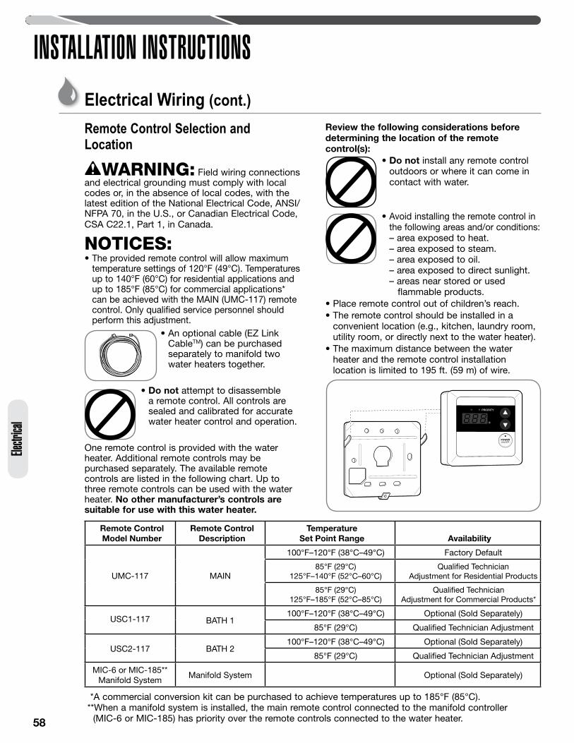
58
INSTALLATION INSTRUCTIONSEle
ctrica
l
Remote Control Selection and Location
WARNING: Field wiring connections and electrical grounding must comply with local codes or, in the absence of local codes, with the latest edition of the National Electrical Code, ANSI/NFPA 70, in the U.S., or Canadian Electrical Code, CSA C22.1, Part 1, in Canada. NOTICES:• The provided remote control will allow maximum
temperature settings of 120°F (49°C). Temperatures up to 140°F (60°C) for residential applications and up to 185°F (85°C) for commercial applications* can be achieved with the MAIN (UMC-117) remote control. Only qualified service personnel should perform this adjustment.
• An optional cable (EZ Link CableTM) can be purchased separately to manifold two water heaters together.
• Do not attempt to disassemble a remote control. All controls are sealed and calibrated for accurate water heater control and operation.
One remote control is provided with the water heater. Additional remote controls may be purchased separately. The available remote controls are listed in the following chart. Up to three remote controls can be used with the water heater. No other manufacturer’s controls are suitable for use with this water heater.
Review the following considerations before determining the location of the remote control(s):
• Do not install any remote control outdoors or where it can come in contact with water.
• Avoid installing the remote control in the following areas and/or conditions:– area exposed to heat. – area exposed to steam. – area exposed to oil. – area exposed to direct sunlight.– areas near stored or used
flammable products.• Place remote control out of children’s reach.• The remote control should be installed in a
convenient location (e.g., kitchen, laundry room, utility room, or directly next to the water heater).
• The maximum distance between the water heater and the remote control installation location is limited to 195 ft. (59 m) of wire.
Remote Control Model Number
Remote Control Description
Temperature Set Point Range Availability
UMC-117 MAIN
100°F–120°F (38°C–49°C) Factory Default
85°F (29°C) 125°F–140°F (52°C–60°C)
Qualified Technician Adjustment for Residential Products
85°F (29°C) 125°F–185°F (52°C–85°C)
Qualified Technician Adjustment for Commercial Products*
USC1-117 BATH 1100°F–120°F (38°C–49°C) Optional (Sold Separately)
85°F (29°C) Qualified Technician Adjustment
USC2-117 BATH 2100°F–120°F (38°C–49°C) Optional (Sold Separately)
85°F (29°C) Qualified Technician Adjustment
MIC-6 or MIC-185** Manifold System
Manifold System Optional (Sold Separately)
*A commercial conversion kit can be purchased to achieve temperatures up to 185°F (85°C). **When a manifold system is installed, the main remote control connected to the manifold controller (MIC-6 or MIC-185) has priority over the remote controls connected to the water heater.
Electrical Wiring (cont.)
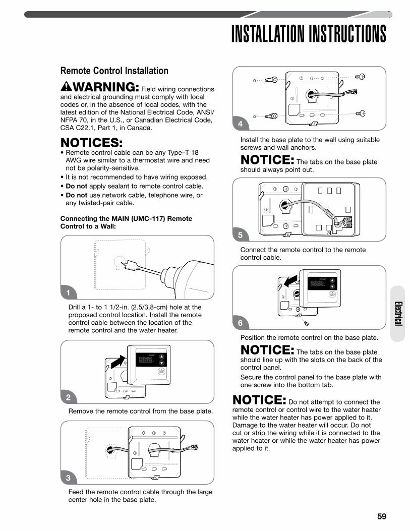
59
INSTALLATION INSTRUCTIONSElectrical
Remote Control InstallationWARNING: Field wiring connections
and electrical grounding must comply with local codes or, in the absence of local codes, with the latest edition of the National Electrical Code, ANSI/NFPA 70, in the U.S., or Canadian Electrical Code, CSA C22.1, Part 1, in Canada. NOTICES:• Remote control cable can be any Type–T 18
AWG wire similar to a thermostat wire and need not be polarity-sensitive.
• It is not recommended to have wiring exposed.• Do not apply sealant to remote control cable.• Do not use network cable, telephone wire, or
any twisted-pair cable.
Connecting the MAIN (UMC-117) Remote Control to a Wall:
Drill a 1- to 1 1/2-in. (2.5/3.8-cm) hole at the proposed control location. Install the remote control cable between the location of the remote control and the water heater.
Remove the remote control from the base plate.
Feed the remote control cable through the large center hole in the base plate.
Install the base plate to the wall using suitable screws and wall anchors.
NOTICE: The tabs on the base plate should always point out.
Connect the remote control to the remote control cable.
Position the remote control on the base plate.
NOTICE: The tabs on the base plate should line up with the slots on the back of the control panel.
Secure the control panel to the base plate with one screw into the bottom tab.
NOTICE: Do not attempt to connect the remote control or control wire to the water heater while the water heater has power applied to it. Damage to the water heater will occur. Do not cut or strip the wiring while it is connected to the water heater or while the water heater has power applied to it.
2
3
4
5
6
1
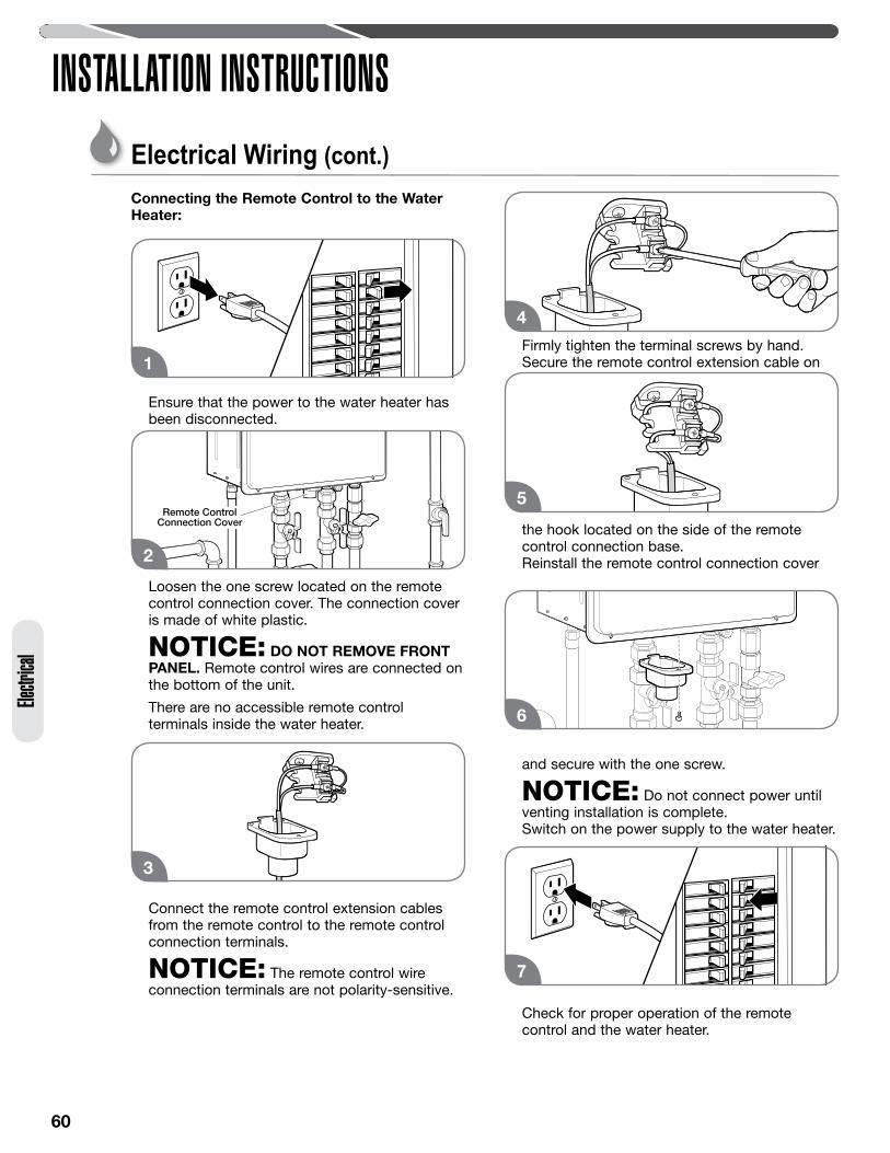
60
INSTALLATION INSTRUCTIONSEle
ctrica
l
Connecting the Remote Control to the Water Heater:
Ensure that the power to the water heater has been disconnected.
Loosen the one screw located on the remote control connection cover. The connection cover is made of white plastic.
NOTICE: DO NOT REMOVE FRONT PANEL. Remote control wires are connected on the bottom of the unit.
There are no accessible remote control terminals inside the water heater.
Connect the remote control extension cables from the remote control to the remote control connection terminals.
NOTICE: The remote control wire connection terminals are not polarity-sensitive.
Firmly tighten the terminal screws by hand. Secure the remote control extension cable on
the hook located on the side of the remote control connection base.
Reinstall the remote control connection cover
and secure with the one screw.
NOTICE: Do not connect power until venting installation is complete.
Switch on the power supply to the water heater.
Check for proper operation of the remote control and the water heater.
1
3
4
Remote ControlConnection CoverRemote Control
Connection Cover
2
5
6
7
Electrical Wiring (cont.)
61
INSTALLATION INSTRUCTIONSElectrical
Insulation BlanketsIn general, insulation blankets for external use on gas water heaters are not necessary. The purpose of an insulation blanket is to reduce the standby heat loss from the water heater’s storage tank. Since these water heaters do not store water, they eliminate the need for the insulation blanket.
WARNINGS: • If local codes require the application of external
insulation blanket kits, carefully follow the manufacturer’s installation instructions included with the kit. Only use blanket kits that are approved for use with your water heater.
• NEVER cover the air inlet, flue outlet, or operating and warning labels attached to the water heater. Operating and warning labels should not be relocated to the exterior of an insulation blanket. Covering these components will cause dangerous operating conditions that can lead to death, personal injury, property damage, and/or product damage.
The manufacturer’s warranty does not cover any damage or defect caused by insulation, insulation attachment, or use of any type of energy-saving or other unapproved devices (unless authorized by the manufacturer). The use of unauthorized energy-saving devices can result in death, personal injury, and/or property damage. The manufacturer disclaims any responsibility for such loss or injury resulting from the use of such unauthorized devices.
Installation Precautions• Follow all installation instructions covered in this
manual.• Check the inlet gas pressure to make sure it is
within the range specified on the rating plate.• Make sure there is adequate air for combustion
and ventilation as described on pages 37–38 or page 44 in this manual.
• Maintain proper clearances to combustibles and noncombustibles as specified on the rating plate.
• Make sure the venting system complies with local codes, National Fuel Gas Codes (ANSI Z223.1/NFPA 54) or CSA B149.1, and the guidelines found on pages 34 through 46 in this manual.
• Contact the local gas company to make sure the gas meter and gas piping are adequately sized.
• Use only Teflon tape on all male water line connections and fittings.
• Do not block or restrict any air intake openings.• Do not remove the front cover unless absolutely
necessary. This should only be done by a qualified service technician.
• Do not install this product where standing water may occur.
• Do not use pipe dope on water line connections and fittings.
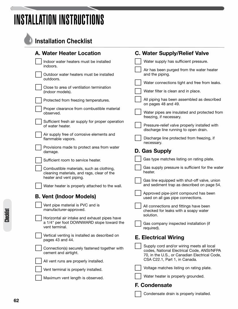
62
INSTALLATION INSTRUCTIONS
Condensate drain is properly installed.
F. Condensate
Installation Checklist
Indoor water heaters must be installed indoors.
Outdoor water heaters must be installed outdoors.
Close to area of ventilation termination (indoor models).
Protected from freezing temperatures.
Proper clearance from combustible material observed.
Sufficient fresh air supply for proper operation of water heater.
Air supply free of corrosive elements and flammable vapors.
Provisions made to protect area from water damage.
Sufficient room to service heater.
Combustible materials, such as clothing, cleaning materials, and rags, clear of the heater and vent piping.
Water heater is properly attached to the wall.
A. Water Heater Location
B. Vent (Indoor Models)
Vent pipe material is PVC and is manufacturer-approved.
Horizontal air intake and exhaust pipes have a 1/4" per foot DOWNWARD slope toward the vent terminal.
Vertical venting is installed as described on pages 43 and 44.
Connection(s) securely fastened together with cement and airtight.
All vent runs are properly installed.
Vent terminal is properly installed.
Maximum vent length is observed.
Water supply has sufficient pressure.
Air has been purged from the water heater and the piping.
Water connections tight and free from leaks.
Water filter is clean and in place.
All piping has been assembled as described on pages 48 and 49.
Water pipes are insulated and protected from freezing, if necessary.
Pressure-relief valve properly installed with discharge line running to open drain.
Discharge line protected from freezing, if necessary.
C. Water Supply/Relief Valve
Gas type matches listing on rating plate.
Gas supply pressure is sufficient for the water heater.
Gas line equipped with shut-off valve, union and sediment trap as described on page 54.
Approved pipe-joint compound has been used on all gas pipe connections.
All connections and fittings have been checked for leaks with a soapy water solution.
Gas company inspected installation (if required).
D. Gas Supply
Supply cord and/or wiring meets all local codes, National Electrical Code, ANSI/NFPA 70, in the U.S., or Canadian Electrical Code, CSA C22.1, Part 1, in Canada.
Voltage matches listing on rating plate.
Water heater is properly grounded.
E. Electrical Wiring
Check
list
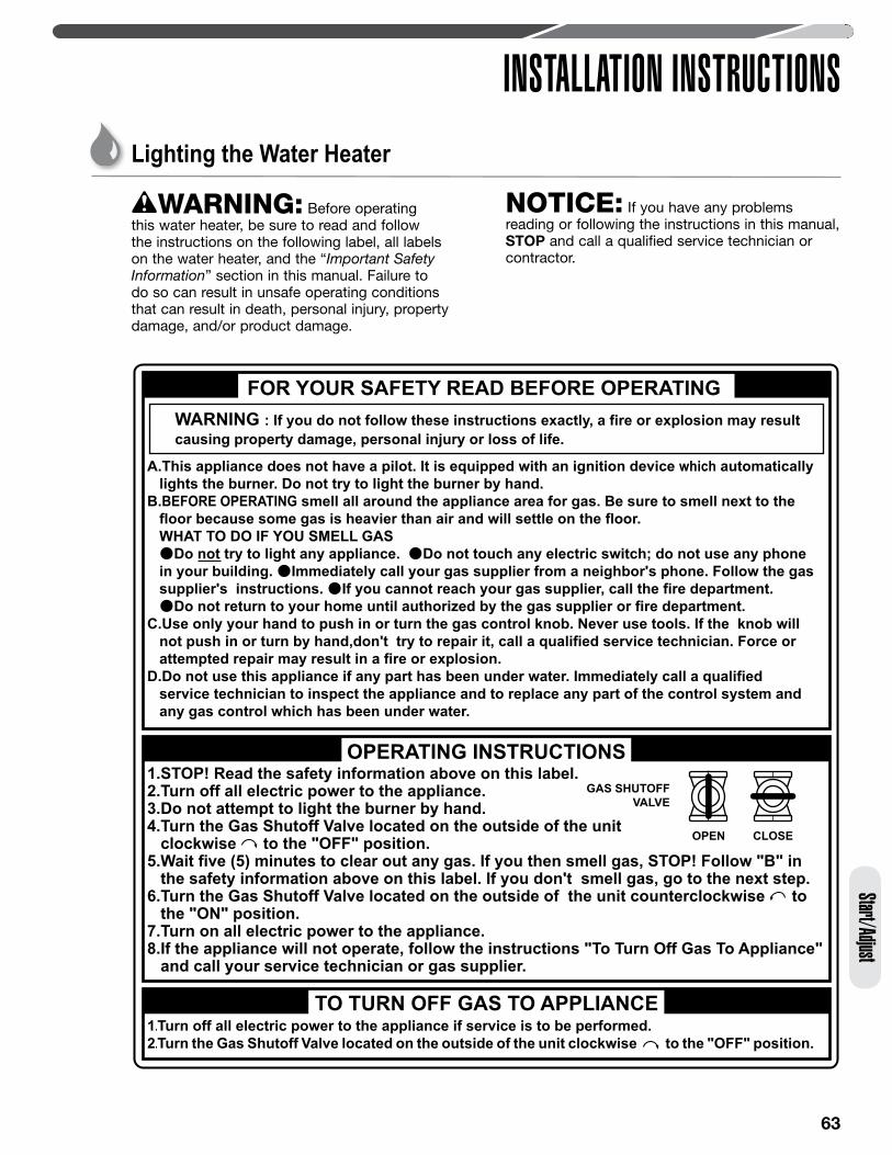
63
INSTALLATION INSTRUCTIONSStart/Adjust
Lighting the Water Heater
WARNING: Before operating this water heater, be sure to read and follow the instructions on the following label, all labels on the water heater, and the “Important Safety Information” section in this manual. Failure to do so can result in unsafe operating conditions that can result in death, personal injury, property damage, and/or product damage.
NOTICE: If you have any problems reading or following the instructions in this manual, STOP and call a qualified service technician or contractor.
WARNING : If you do not follow these instructions exactly, a fire or explosion may resultcausing property damage, personal injury or loss of life.
FOR YOUR SAFETY READ BEFORE OPERATING
1.STOP! Read the safety information above on this label.2.Turn off all electric power to the appliance.3.Do not attempt to light the burner by hand.4.Turn the Gas Shutoff Valve located on the outside of the unit clockwise to the "OFF" position.5.Wait five (5) minutes to clear out any gas. If you then smell gas, STOP! Follow "B" in the safety information above on this label. If you don't smell gas, go to the next step.6.Turn the Gas Shutoff Valve located on the outside of the unit counterclockwise to the "ON" position.7.Turn on all electric power to the appliance.8.If the appliance will not operate, follow the instructions "To Turn Off Gas To Appliance" and call your service technician or gas supplier.
TO TURN OFF GAS TO APPLIANCE 1.Turn off all electric power to the appliance if service is to be performed.
2.Turn the Gas Shutoff Valve located on the outside of the unit clockwise to the "OFF" position.
GAS SHUTOFF VALVE
OPEN CLOSE
OPERATING INSTRUCTIONS
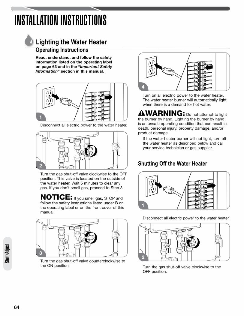
64
INSTALLATION INSTRUCTIONSSta
rt/Ad
just
Operating InstructionsRead, understand, and follow the safety information listed on the operating label on page 63 and in the “Important Safety Information” section in this manual.
Disconnect all electric power to the water heater.
Turn the gas shut-off valve clockwise to the OFF position. This valve is located on the outside of the water heater. Wait 5 minutes to clear any gas. If you don’t smell gas, proceed to Step 3.
NOTICE: If you smell gas, STOP and follow the safety instructions listed under B on the operating label or on the front cover of this manual.
Turn the gas shut-off valve counterclockwise to the ON position.
Turn on all electric power to the water heater. The water heater burner will automatically light when there is a demand for hot water.
WARNING: Do not attempt to light the burner by hand. Lighting the burner by hand is an unsafe operating condition that can result in death, personal injury, property damage, and/or product damage. If the water heater burner will not light, turn off
the water heater as described below and call your service technician or gas supplier.
Shutting Off the Water Heater
Disconnect all electric power to the water heater.
Turn the gas shut-off valve clockwise to the OFF position.
1
2
3
4
1
2
Lighting the Water Heater
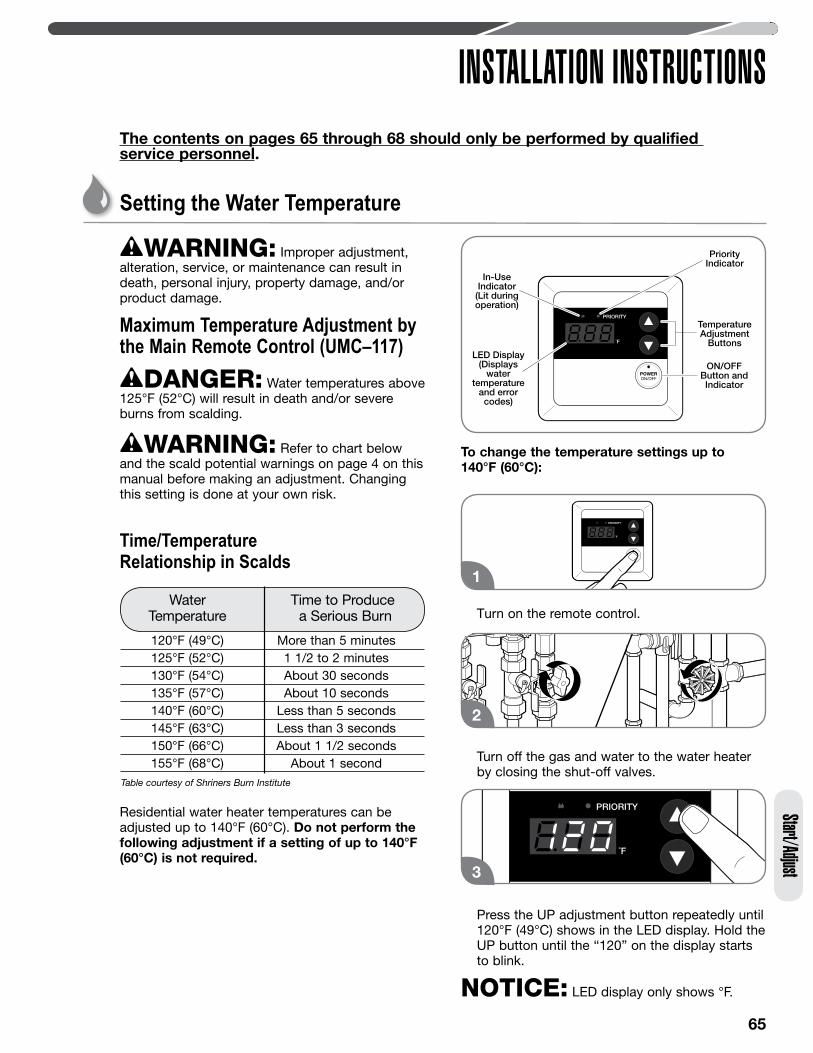
65
INSTALLATION INSTRUCTIONSStart/Adjust
Setting the Water Temperature
WARNING: Improper adjustment, alteration, service, or maintenance can result in death, personal injury, property damage, and/or product damage.
Maximum Temperature Adjustment by the Main Remote Control (UMC–117)
DANGER: Water temperatures above 125°F (52°C) will result in death and/or severe burns from scalding.
WARNING: Refer to chart below and the scald potential warnings on page 4 on this manual before making an adjustment. Changing this setting is done at your own risk.
Residential water heater temperatures can be adjusted up to 140°F (60°C). Do not perform the following adjustment if a setting of up to 140°F (60°C) is not required.
To change the temperature settings up to 140°F (60°C):
Turn on the remote control.
Turn off the gas and water to the water heater by closing the shut-off valves.
Press the UP adjustment button repeatedly until 120°F (49°C) shows in the LED display. Hold the UP button until the “120” on the display starts to blink.
NOTICE: LED display only shows °F.
Time/Temperature Relationship in Scalds
Water Time to Produce Temperature a Serious Burn
120°F (49°C) More than 5 minutes 125°F (52°C) 1 1/2 to 2 minutes 130°F (54°C) About 30 seconds 135°F (57°C) About 10 seconds 140°F (60°C) Less than 5 seconds 145°F (63°C) Less than 3 seconds 150°F (66°C) About 1 1/2 seconds 155°F (68°C) About 1 secondTable courtesy of Shriners Burn Institute
The contents on pages 65 through 68 should only be performed by qualified service personnel.
In-UseIndicator(Lit duringoperation)
PriorityIndicator
TemperatureAdjustment
Buttons
ON/OFFButton andIndicator
LED Display(Displays
watertemperature
and errorcodes)
1
2
3
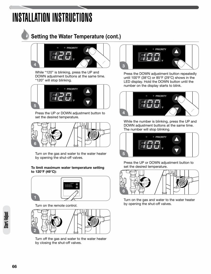
66
Start/
Adjus
t
INSTALLATION INSTRUCTIONS
While “120” is blinking, press the UP and DOWN adjustment buttons at the same time. “120” will stop blinking.
Press the UP or DOWN adjustment button to set the desired temperature.
Turn on the gas and water to the water heater by opening the shut-off valves.
To limit maximum water temperature setting to 120°F (49°C):
Turn on the remote control.
Turn off the gas and water to the water heater by closing the shut-off valves.
Press the DOWN adjustment button repeatedly until 100°F (38°C) or 85°F (29°C) shows in the LED display. Hold the DOWN button until the number on the display starts to blink.
While the number is blinking, press the UP and DOWN adjustment buttons at the same time. The number will stop blinking.
Press the UP or DOWN adjustment button to set the desired temperature.
Turn on the gas and water to the water heater by opening the shut-off valves.
4
5
6
1
2
3
4
5
6
Setting the Water Temperature (cont.)
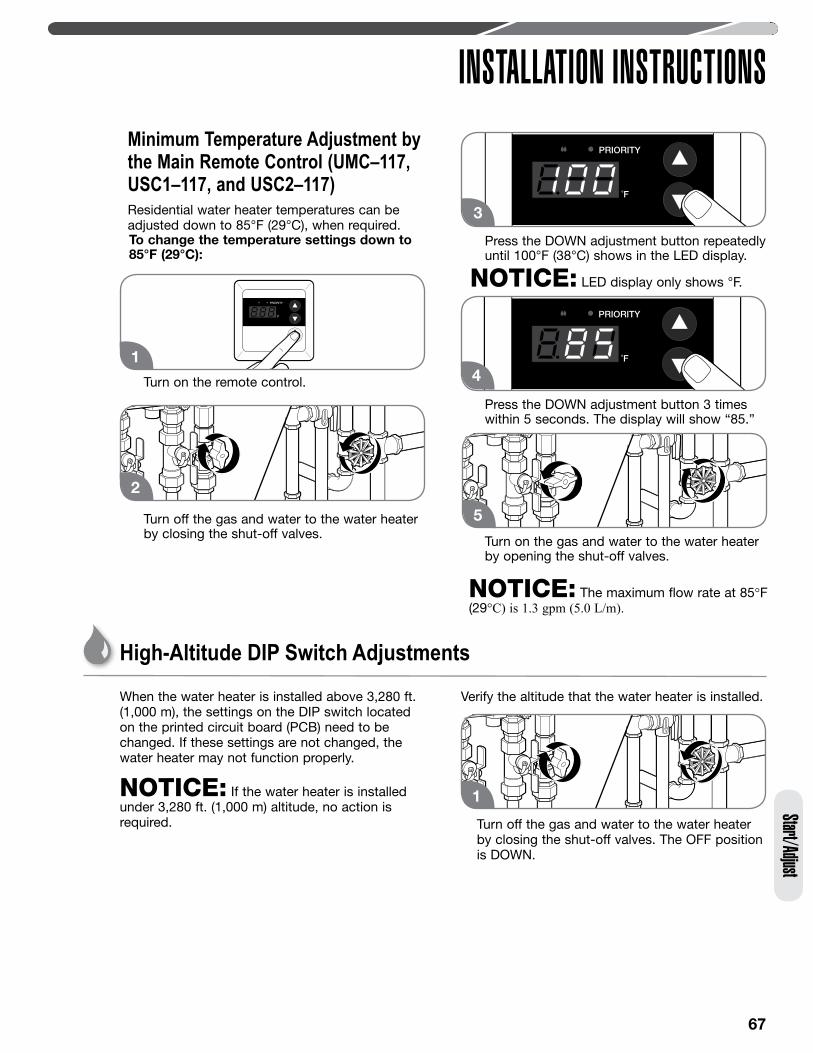
67
Minimum Temperature Adjustment by the Main Remote Control (UMC–117, USC1–117, and USC2–117) Residential water heater temperatures can be adjusted down to 85°F (29°C), when required.To change the temperature settings down to 85°F (29°C):
Turn on the remote control.
Turn off the gas and water to the water heater by closing the shut-off valves.
Press the DOWN adjustment button repeatedly until 100°F (38°C) shows in the LED display.
NOTICE: LED display only shows °F.
Press the DOWN adjustment button 3 times within 5 seconds. The display will show “85.”
Turn on the gas and water to the water heater by opening the shut-off valves.
NOTICE: The maximum flow rate at 85°F (29°C) is 1.3 gpm (5.0 L/m).
INSTALLATION INSTRUCTIONSStart/Adjust
When the water heater is installed above 3,280 ft. (1,000 m), the settings on the DIP switch located on the printed circuit board (PCB) need to be changed. If these settings are not changed, the water heater may not function properly.
NOTICE: If the water heater is installed under 3,280 ft. (1,000 m) altitude, no action is required.
Verify the altitude that the water heater is installed.
Turn off the gas and water to the water heater by closing the shut-off valves. The OFF position is DOWN.
1
2
4
5
High-Altitude DIP Switch Adjustments
1
3
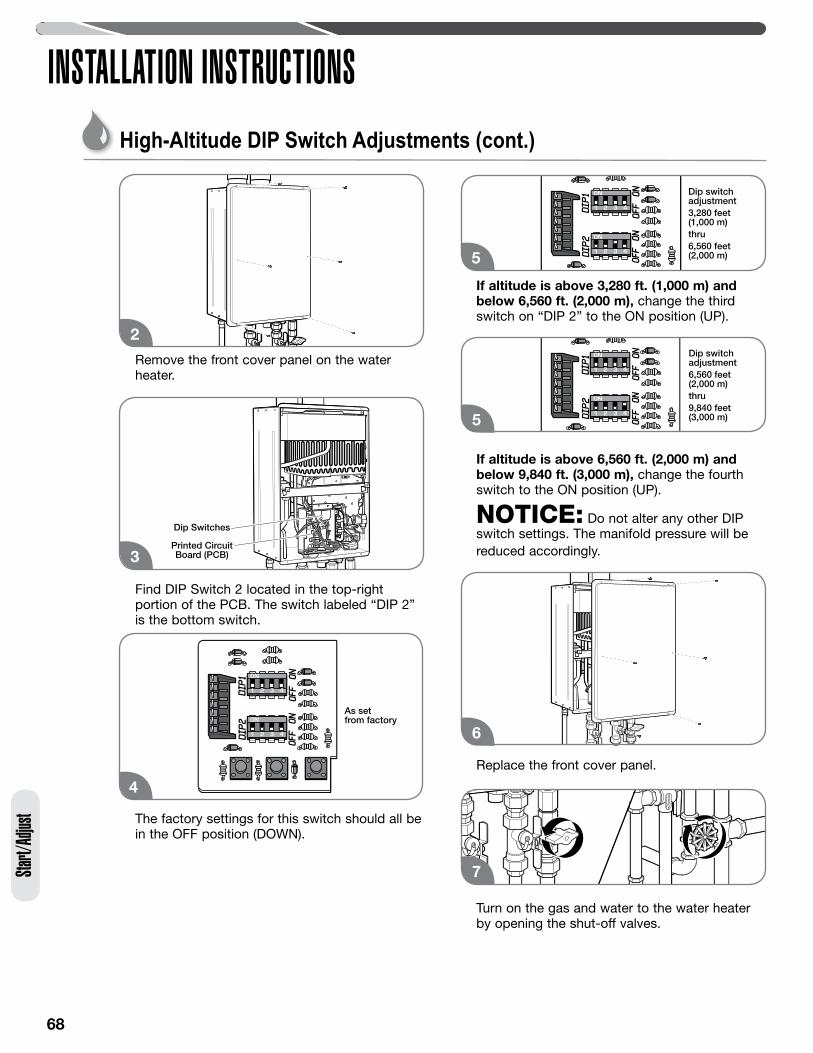
68
INSTALLATION INSTRUCTIONSSta
rt/Ad
just
High-Altitude DIP Switch Adjustments (cont.)
Printed CircuitBoard (PCB)
Dip Switches
3
Dip switch adjustment3,280 feet (1,000 m)thru6,560 feet (2,000 m)5
2
Remove the front cover panel on the water heater.
Find DIP Switch 2 located in the top-right portion of the PCB. The switch labeled “DIP 2” is the bottom switch.
The factory settings for this switch should all be in the OFF position (DOWN).
If altitude is above 3,280 ft. (1,000 m) and below 6,560 ft. (2,000 m), change the third switch on “DIP 2” to the ON position (UP).
If altitude is above 6,560 ft. (2,000 m) and below 9,840 ft. (3,000 m), change the fourth switch to the ON position (UP).
NOTICE: Do not alter any other DIP switch settings. The manifold pressure will be reduced accordingly.
Replace the front cover panel.
Turn on the gas and water to the water heater by opening the shut-off valves.
7
As setfrom factory
4
Dip switchadjustment6,560 feet(2,000 m)thru9,840 feet(3,000 m)5
6
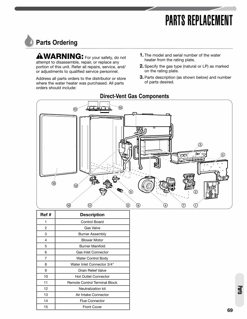
69
PARTS REPLACEMENTParts
Parts Ordering
WARNING: For your safety, do not attempt to disassemble, repair, or replace any portion of this unit. Refer all repairs, service, and/or adjustments to qualified service personnel.
Address all parts orders to the distributor or store where the water heater was purchased. All parts orders should include:
1. The model and serial number of the water heater from the rating plate.
2. Specify the gas type (natural or LP) as marked on the rating plate.
3. Parts description (as shown below) and number of parts desired.
Direct-Vent Gas Components
Ref # Description
1 Control Board
2 Gas Valve
3 Burner Assembly
4 Blower Motor
5 Burner Manifold
6 Gas Inlet Connector
7 Water Control Body
8 Water Inlet Connector 3/4"
9 Drain Relief Valve
10 Hot Outlet Connector
11 Remote Control Terminal Block
12 Neutralization kit
13 Air Intake Connector
14 Flue Connector
15 Front Cover
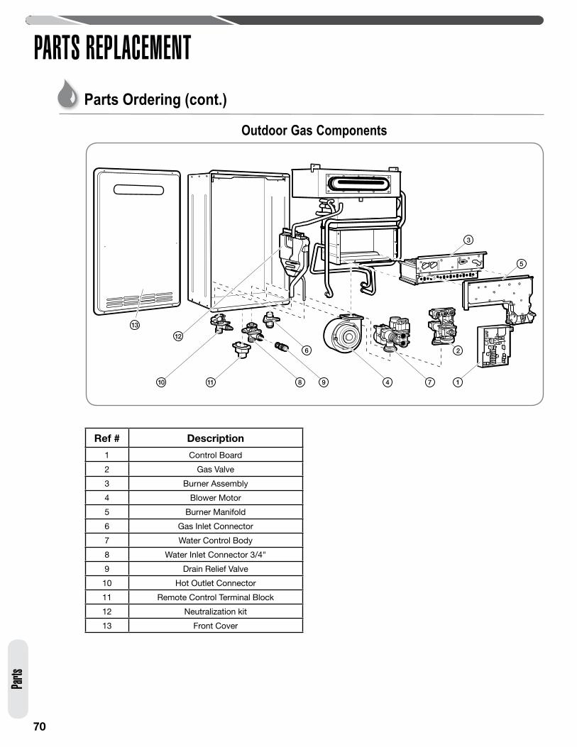
70
PARTS REPLACEMENTParts Ordering (cont.)
Parts
Outdoor Gas Components
Ref # Description
1 Control Board
2 Gas Valve
3 Burner Assembly
4 Blower Motor
5 Burner Manifold
6 Gas Inlet Connector
7 Water Control Body
8 Water Inlet Connector 3/4"
9 Drain Relief Valve
10 Hot Outlet Connector
11 Remote Control Terminal Block
12 Neutralization kit
13 Front Cover
71
NOTES
72
NOTES