Embed Size (px)
Citation preview

Tapio Terävä
Workflows for Creating 3D Game Characters
Bachelor of Business
Administration
Business Information
Technology
Spring 2017


TIIVISTELMÄ
Tekijä: Tapio Terävä
Työn nimi: Työtapoja 3D pelihahmojen luomiseen
Tutkintonimike: Tradenomi (AMK), Tietojenkäsittely
Asiasanat: peli, hahmo, pelihahmo, 3D, työtapa
Opinnäytetyö käsittelee 3D pelihahmojen luomiseen käytettäviä erilaisia työtapoja, sekä niissä käy-
tettäviä eri työkaluja. Lisäksi opinnäytetyö pyrkii luomaan kokonaisvaltaisen kuvan 3D pelihahmo-
jen luomisprosessista, siihen liittyvistä keskeisistä teknologioista, sekä rajoituksista joita erilaiset
pelialustat asettavat hahmojen luomiselle.
Opinnäytetyö käsittelee alkuun pelihahmojen luomisen eri lähtökohtia, sekä hahmosuunnittelun eri
käytäntöjä ja työtapoja. Seuraavaksi käydään läpi yleistetty esimerkki 3D pelihahmon luomispro-
sessista, johon sisältyy useita eri työvaiheita. Yleistetyn esimerkin jälkeen esitellään tästä poik-
keavia työtapoja, joiden eroavaisuudet johtuvat eri pelialustojen asettamista rajoitteista tai niiden
tarjoamista mahdollisuuksista. Lopuksi vertaillaan miten perinteiset työtavat eroavat nykyaikaisista
työtavoista, ja esitellään uusien työtapojen etuja.
ABSTRACT
Author: Tapio Terävä
Title of the Publication: Workflows for Creating 3D Game Characters
Degree Title: Bachelor of Business Administration (UAS), Business Information Technology
Keywords: game, character, game character, 3D, workflow
This thesis deals with the various workflows, methods, and tools used for creating 3D game char-
acters. The objective of the thesis was to construct a complete picture of the creation process of
3D game characters, and the related technologies essential to the process, as well as the re-
strictions set by different game platforms.
First, the different motives for creating game characters are introduced, along with the different
practices and methods used for designing characters. This is followed by a generalized example
of the process of creating a 3D game character, which consists of several different stages. After
this generalized example, workflows deviating from this example are introduced. The differences
between these workflows are caused by the restrictions set by different game platforms, or the
possibilities they offer. In the final chapters, differences between traditional workflows and modern
workflows are discussed, and the advantages of modern workflows are presented. Finally, the
thesis is concluded by summarizing how games and artists are affected by the different workflows,
tools, and technologies.

ALKUSANAT
Omistettu perheelleni. Kiitos kaikesta tuesta mitä olen saanut opiskelujeni aikana.
TABLE OF CONTENTS
1 INTRODUCTION ............................................................................................... 1
2 GAME CHARACTERS ...................................................................................... 3
2.1 General game character design principles ........................................... 3
2.2 General game character design workflow ............................................ 7
3 3D GAME CHARACTER WORKFLOWS ........................................................ 11
3.1 General workflow ................................................................................ 11
3.1.1 Concept art ............................................................................ 12
3.1.2 3D modeling .......................................................................... 12
3.1.3 UV mapping .......................................................................... 18
3.1.4 Texturing ............................................................................... 23
3.1.5 Rigging .................................................................................. 30
3.1.6 Animation .............................................................................. 36
3.2 Methods and techniques for games on mobile and low-end devices . 47
3.3 Workflows for games on game consoles and computers ................... 56
3.3.1 Traditional workflows ............................................................. 56
3.3.2 Current generation workflows ................................................ 61
3.3.3 Other workflows .................................................................... 64
4 CURRENT GENERATION TOOLS AND TECHNIQUES ................................ 69
4.1 Digital sculpting .................................................................................. 69
4.1.1 General digital sculpting workflow ......................................... 70
4.2 Physically based rendering ................................................................ 77
4.2.1 Specular-Glossiness ............................................................. 82
4.2.2 Metallic-Roughness ............................................................... 84
4.3 Workflows for creating PBR content ................................................... 87
4.3.1 Workflows using traditional tools ........................................... 88
4.3.2 Workflows using modern tools .............................................. 90
5 CONCLUSION ................................................................................................ 98
REFERENCES ................................................................................................... 99
LIST OF FIGURES ........................................................................................... 139
SYMBOLS
Video game Interactive game played using an electronic device, such as a computer, mobile device or a game console.
Game character Character in a game, especially a video game.
Gameplay The way players interact with a game. The experience of playing a game, excluding graphics and sound.
Player character Video game character that is controlled by the player.
Non-player character Video game character that is not controlled by the player, but by the game’s artificial intelligence.
3D model A representation of a three-dimensional object in a computer software environment.
3D modeling The process of creating and shaping a 3D model in a 3D modeling software.
Workflow The progression of steps in a process of creating something, for example a game character.
Lore In the context of games, the history, legends, locations, nature, and characters of the game’s universe.
Story bible A document describing the important aspects of a game’s storyline, lore, characters, and so on.
Pre-production The preparatory stages before starting the actual pro-duction of a project, like making concept art and the lore.
Target device The device on which an application, such as a video game, is intended to be run on.
(Game) Asset Any individual piece of content that can be used in a game, such as a 3D model, a texture, or a sound effect.
Pipeline The different stages and processes that an asset or a project goes through, from idea to final product.
Computational power The ability of a computer to perform a certain amount of work within a given timeframe.
Base mesh A low poly 3D model that can be used as the starting point for digital sculpting.
(Computer) Program A list of instructions for a computer, which tell it to do a particular task. Computers require programs to be used.
Software A general term used for all computer programs, such as operating systems like Windows, as well as video games.
Hardware A general term for all the physical parts that make up a computer, or an electronic device like a mobile phone.
Game engine A software framework used to create video games, which includes helpful tools for efficient development.
(Image) Resolution The amount of detail in an image. For digital images, this is measured in the number of pixels in an image.
Plugin A software component that adds a specific functionality to an existing program. Also called addon or extension.
(Game) Performance How well a game runs on a device. In some cases, bad performance can even make a game unplayable.
(Computer) Memory Where a computer stores information, specifically tem-porary information for programs. Also called RAM.
(Computer) Storage space
Where a computer stores permanent information, such as files and programs. Often either HDD or SSD.
User interface The interface used to interact with a computer, such as the input devices and the visual elements of a software.
Procedural (Genera-tion)
A method of creating data, like textures or animations, algorithmically instead of manually.
Sine wave A mathematical curve that describes a smooth repeating oscillation. Named after the sine function.
Triangle wave A triangular waveform that is not a pure sine wave. Can be derived from simple math functions.
Boolean operations Logical operations that can be performed on 3D models, such as add or subtract. Based on Boolean algebra.

1
1 INTRODUCTION
3D game characters have come a long way since the early days of 3D games.
Classics like Quake and Tomb Raider paved the way for modern 3D characters in
games, and since then the advancements in video game technology have brought
us to an era where it is sometimes possible to forget that the character you are
looking at is not a real person, but is instead a digital work of art constructed by
highly skilled professionals. However, we are still a long way from complete real-
ism, and new technologies are constantly being developed in order to reach the
next big milestone in the evolution of video game graphics.
Of course, not all game characters need to be realistic. Most likely, there will al-
ways be a place for more stylized games, with cartoony, exaggerated, and goofy
characters. Just like there are gritty, action packed live-action movies, and heart-
warming computer-animated films, not to forget the brilliantly hand-drawn classics,
there is also room for equal variety in the medium of video games. After all, video
games can be considered an art form of their own, and art comes in many shapes
and sizes.
Another factor that adds variety to the mix are the technical restrictions set by
different game platforms. Game characters in games developed for powerful com-
puters and modern game consoles can take advantage of the new technologies,
allowing them to look more realistic than before. In comparison, game characters
in games developed for less powerful devices like mobile phones have to settle for
using older, outdated technologies, requiring artists to come up with different kinds
of tricks to make the best of what they have at their disposal.
Knowing all this, the scope of this thesis might seem very frightening at first, since
it aims to construct a comprehensive picture of the different workflows of creating
3D game characters, with relatively detailed descriptions and explanations of the
related concepts and methods. However, this thesis is intended to be understand-
able even for people who are not familiar with game development. Many of the

2
concepts are described and explained using simple examples, and the structure
of the thesis follows the different steps of creating a 3D game character from start
to finish, before moving on to descriptions of alternative workflows. Therefore, I
encourage you to keep on reading, especially if you are interested in game char-
acters, or game development in general.
3
2 GAME CHARACTERS
Characters are an essential part of all story based mediums, like books, films and
video games. Therefore, creating good characters that fit the medium’s needs is
very important, and the process should be given plenty of resources like time and
manpower during the project. The process of designing a character can consist of
creating a unique personality and backstory for the character, as well as defining
their goals, motives and needs. However, this chapter will focus only on the visual
design of characters, specifically the visual design of video game characters. [1,
p10] [1, p15-27]
2.1 General game character design principles
Developing the visual design of a game character can be approached in different
ways, depending on the style of the game and the intended use of the character.
The different kinds of character designs in games can be roughly divided into two
different types: art-driven character designs and story-driven character designs.
An art-driven character design takes the visual appearance of the character as the
primary focus during the development, while the backstory and character traits
become less important for the overall design. Art-driven character designs rely
heavily on art principles like shape, form, color, and value to convey the charac-
ter’s personality, talents and abilities to the player. These features can be exag-
gerated even further in order to clearly express the role and functionality of the
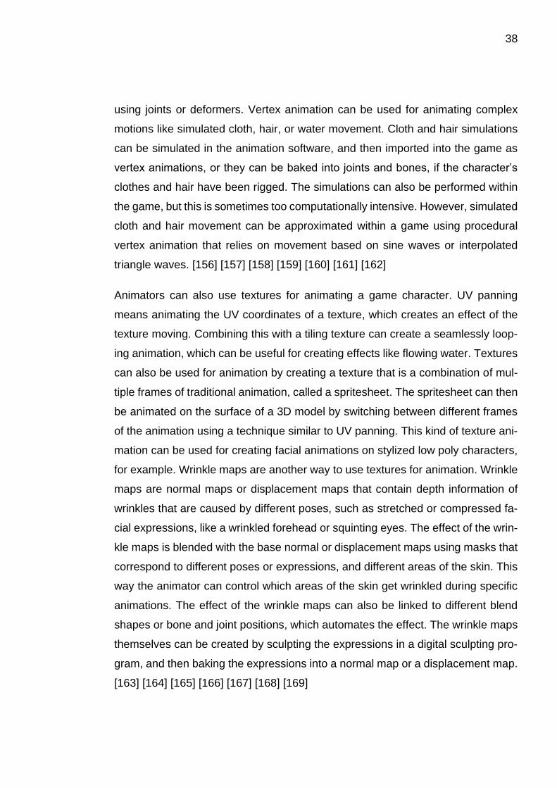
character. The aforementioned principles of art can also be used to design the
character so that its features support the gameplay of the game. For example, the
size of the facial features like eyes could be a design choice to help the players
understand where the character is looking, or which way the character is facing.
Art-driven character designs could be viewed as puppets or avatars which the

4
player controls, and are often used in simple games which focus more on game-
play instead of storytelling. [1, p59-61] [2, p121-129]
Figure 1. Art-driven characters in Rovio’s Angry Birds. Adapted by author.
Story-driven character designs focus on the backstory and the personality of the
character, which can be conveyed through the character’s behavior, like quirks
and habits. Therefore, not every aspect of the character has to be visually repre-
sented, at least in an obvious way, and so the story-driven character designs often
rely less on the appearance of the character and exaggeration of the visual fea-
tures when compared to art-driven character designs. [1, p61-62] [2, p130-135]
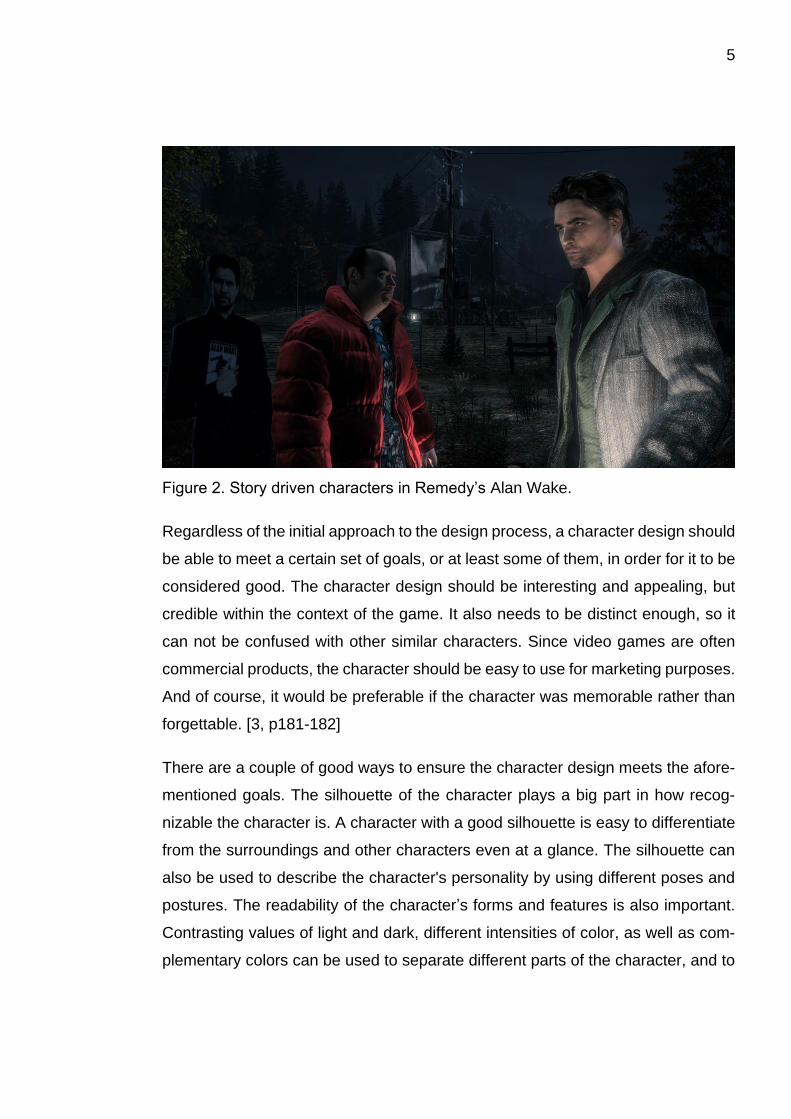
5
Figure 2. Story driven characters in Remedy’s Alan Wake.
Regardless of the initial approach to the design process, a character design should
be able to meet a certain set of goals, or at least some of them, in order for it to be
considered good. The character design should be interesting and appealing, but
credible within the context of the game. It also needs to be distinct enough, so it
can not be confused with other similar characters. Since video games are often
commercial products, the character should be easy to use for marketing purposes.
And of course, it would be preferable if the character was memorable rather than
forgettable. [3, p181-182]
There are a couple of good ways to ensure the character design meets the afore-
mentioned goals. The silhouette of the character plays a big part in how recog-
nizable the character is. A character with a good silhouette is easy to differentiate
from the surroundings and other characters even at a glance. The silhouette can
also be used to describe the character's personality by using different poses and
postures. The readability of the character’s forms and features is also important.
Contrasting values of light and dark, different intensities of color, as well as com-
plementary colors can be used to separate different parts of the character, and to
6
draw attention to the most important features of the character. [4, p74-78] [5, p8-
14] [6] [7]
Basing the character on real-world examples is a good way to make the design
more believable. If the character is human, paying attention to human proportions
and anatomy is important. However, this does not mean that the design has to be
realistic. The proportions can be exaggerated to make the character more dynamic
and interesting, or to achieve a specific stylized look. If the character is an animal
or a monster of some sort, it is important that the creature remains believable,
even if the design is highly stylized. Gathering reference on different animals and
looking at their anatomy, movement, and other characteristics makes it easier to
design realistic, or at least plausible creatures. [5, p3-7] [8, p3-5] [9]
It is also good to remember the “form follows function” rule of thumb, which basi-
cally means that the design should look like it could actually physically work if the
character was real, and that there is a reason for why the character looks like it
does. This is especially important when designing clothing and armor, or some-
thing mechanical like robots and cyborgs. If a warrior character has huge pointy
shoulder pads, what happens when the character tries to raise his arms? In the
real world, he would either end up hitting the pads against his head, or would not
be able to lift his arms at all. Similarly, a robot’s limbs need to have enough space
to move around, and they need to use appropriate parts for the joints (compare a
ball joint to a hinge joint). If a 3D model is made based on a character design
where form does not follow function, different parts of the model can end up inter-
secting unnaturally with other parts during animation, which is called clipping.
Some clipping will occur almost always, and it can be acceptable if the character
is viewed from a distance, or if the clipping happens during a movement that is so
fast the player will not be able to notice it, but it is good practice to try and avoid it
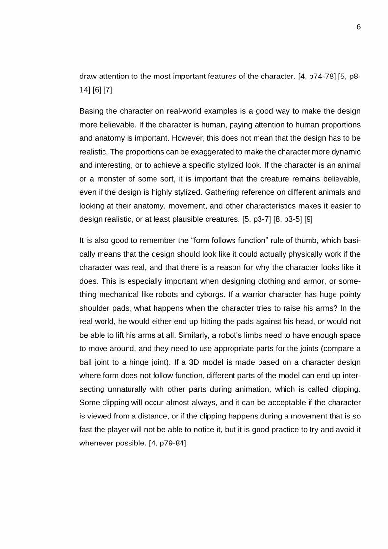
whenever possible. [4, p79-84]
7
Figure 3. Armor clipping in Crytek’s Ryse: Son of Rome (lower right corner).
Of course, there are exceptions to these rules. A ghost, for example, does not
have to be based on anything that can be found in the real world. However, it might
be wise to look at how ghosts are traditionally portrayed in other contexts, like in
films, comics, and other video games, and use those portrayals as guidelines
when designing, so that it is clear to the player that the character is indeed a ghost.
2.2 General game character design workflow
The process of designing a game character often starts with coming up with certain
guidelines for the design. These guidelines can be as simple as a small selection
of keywords that define the key characteristics of the character, such as adjectives
or metaphors describing the character’s size, shape, age, attitude, behavior, and
so on. After creating the initial list of keywords, the list can be supplemented with
words that are conceptually in opposition to the original words, which can add more
depth and contrast to the character design, making it more interesting. This list of
keywords can then be converted into a compact written description of the charac-
ter, a so-called high concept. The keywords can also be used for gathering visual
8
research for the character, by typing them into an internet search engine like
Google, and searching for images that represent the keywords, for example.
[10, p2]
Sometimes game characters are based on existing character concepts, for exam-
ple if the game is based on licensed content such as a movie or a book. Even in
games that are not based on any licensed content, the characters of the game
may have been strictly defined in the lore of the game, written into a so-called story
bible, which was made during the pre-production. In these cases, there are usually
more restrictions on what the designers and artists can do, since the character is
based on a fully fleshed concept, and not a relatively vague high concept. How
strict these restrictions are depends on the source material and the licensor.
Mickey Mouse, for example, has a very thoroughly defined appearance and per-
sonality, whereas some characters in books can be very open to interpretation.
[11, p62-63] [12, p314] [13, p311-312] [14]
After the general guidelines for the character design have been defined, the next
step in the process is usually creating initial sketches and concept art for the char-
acter. There are various sketching techniques that concept artists can use in their
design process. A common way to start out is to draw several small black-and-
white silhouettes or grayscale sketches of the character, which can be done very
fast and loosely. These are called thumbnail sketches or simply thumbnails, and
their purpose is to let the artist explore multiple different ideas quickly. Once there
are enough thumbnails the artist and his team can choose which thumbnails or
which specific elements in those should be refined further. The next set of sketches
could be thumbnails that combine elements from the previous sketches, or some
of the first thumbnails could be improved on by creating more detailed sketches
based on them. This practice of improving on previous versions and making
changes based on feedback is called iteration, and it can repeat for several cycles
until the artist, or his superiors, are satisfied with the result. Iteration often happens
at every step of making games, not just when creating concept art. Next step, once
the initial look of the character has been defined, is to create colored sketches, or
to simply color over the grayscale sketches. It is common to create different color
9
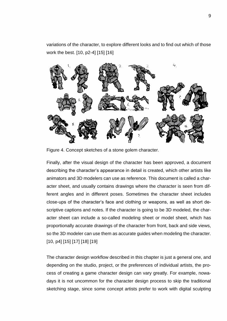
variations of the character, to explore different looks and to find out which of those
work the best. [10, p2-4] [15] [16]
Figure 4. Concept sketches of a stone golem character.
Finally, after the visual design of the character has been approved, a document
describing the character’s appearance in detail is created, which other artists like
animators and 3D modelers can use as reference. This document is called a char-
acter sheet, and usually contains drawings where the character is seen from dif-
ferent angles and in different poses. Sometimes the character sheet includes
close-ups of the character’s face and clothing or weapons, as well as short de-
scriptive captions and notes. If the character is going to be 3D modeled, the char-
acter sheet can include a so-called modeling sheet or model sheet, which has
proportionally accurate drawings of the character from front, back and side views,
so the 3D modeler can use them as accurate guides when modeling the character.
[10, p4] [15] [17] [18] [19]
The character design workflow described in this chapter is just a general one, and
depending on the studio, project, or the preferences of individual artists, the pro-
cess of creating a game character design can vary greatly. For example, nowa-
days it is not uncommon for the character design process to skip the traditional
sketching stage, since some concept artists prefer to work with digital sculpting

10
programs such as ZBrush or Autodesk Mudbox. These programs allow the artists
to create detailed concept 3D models by sculpting “digital clay”. Because all of the
work is done digitally, it is possible to quickly create multiple variations of the base
concept and make edits to the concepts based on feedback, without losing any of
the previous versions. Once the final concept is approved, it is already a 3D model,
which makes it easier to create a game ready 3D model based on the concept 3D
model. Sometimes the digitally sculpted concept 3D model is converted straight
into the game ready 3D model using a method called retopologizing, which will be
described further in the following chapters. [8, p1] [20]

11
3 3D GAME CHARACTER WORKFLOWS
Workflows for creating 3D game characters can have big differences depending
on things like the technical limitations of the target device, the artistic style of the
game, whether the character is a main character or a background character, how
the character is going to be animated, and is the character organic like an animal,
or inorganic like a robot. Other things that can affect the workflows are differences
between game studios, such as the number of dedicated artists, the employee
hierarchy of the studio, the software used at the studio, and specific asset pipelines
that are used exclusively by certain studios. To begin with, this chapter will give
an overview of a general workflow for creating a 3D game character, and will then
describe the specific methods and techniques used in other common workflows.
3.1 General workflow
This description of a general workflow focuses on the different steps of creating
3D game characters using traditional tools and techniques commonly used in the
game industry, and is described from the point of view of an asset production pipe-
line in a game studio where different steps are done by different professionals.
However, this is not the definitive workflow for creating 3D game characters, but
just one example of how the process could be executed. For example, in a small
independent game studio all of the following steps could be performed by a single
artist, instead of several specialized artists dedicated to each different task. In ad-
dition to describing the different steps in the workflow of creating a 3D game char-
acter, some of the technical concepts related to the process will also be explained,
as well as how artists need to take them into consideration in their work.

12
3.1.1 Concept art
As explained in the previous chapter, the process of creating a game character
usually begins with creating concept art for the character, which in the case of a
3D character may include specific documents called model sheets. These model
sheets, together with other pieces of concept art, are used by the 3D modeler as
guides for creating the 3D model of the character, similarly how construction work-
ers use blueprints made by an architect as guides to construct buildings. The 3D
modeler can import the images into the 3D modeling program, where they can
then apply the images onto 3D planes. These images can then be used as exact
guides which the modeler attempts to follow as accurately as possible. However,
the 3D model often differs slightly from the original modeling sheet. Sometimes
changes need to be made because of technical restrictions, and sometimes the
3D modeler is given some creative freedom to interpret and change the design. It
is also possible that the original images in the modeling sheet were not proportion-
ally accurate, or the character’s poses were not correctly portrayed from different
angles. [21]
3.1.2 3D modeling
There are many different ways to construct a 3D model, depending on which soft-
ware is used, what the model is going to be used for, as well as which modeling
techniques the 3D modeler prefers to use. For example, computer-aided design
editors like Autodesk AutoCAD can be used to create 3D models that have prop-
erties like being solid inside the three-dimensional surface, and digital sculpting
programs like ZBrush and Mudbox allow the 3D modeler to sculpt the model out
of “digital clay”. Since this is a description of the general workflow of creating a 3D
game character, the following paragraphs will first cover the 3D modeling process
using more traditional polygonal modeling tools. Also, because computer-aided

13
design editors are mostly used in industrial design and are not widely used in com-
puter games, that subject will not be covered in this thesis. However, the subject
of digital sculpting will be addressed later on. [22] [23]
In traditional polygonal modeling programs, such as Autodesk 3ds Max, Autodesk
Maya, and Blender, 3D models are constructed by creating 3D surfaces out of
shapes called polygons. Polygons are geometric planes, or faces, which consist
of units called vertices and edges. Vertices (sg. vertex) are essentially points in
three-dimensional space, and can also have a property called a normal, which
defines the direction where the vertex is facing. When vertices are connected, they
form edges, and when there are at least three vertices connected to each other in
the shape of a triangle, they can form a polygon. Polygons can also be created out
of four vertices in the shape of a quadrilateral, like a rectangle, in which case they
are called quads. If a polygon has more than four vertices, it is called an n-gon.
The normals of the faces or vertices in a polygon determine which direction the
polygon’s visible surface is facing. By creating, connecting and manipulating these
vertices, edges, and polygons, a 3D modeler can create three-dimensional sur-
faces, called meshes, which all complex polygonal 3D models, like game charac-
ters, consist of. [24] [25]
Figure 5. The basic components of a polygonal 3D model. Adapted by author.
14
When creating 3D models, a 3D modeler has several different techniques and
tools at his disposal. Two common approaches to polygonal modeling are box
modeling and edge modeling. In box modeling the 3D modeler starts out with a
pre-made primitive shape, such as a cube, a cylinder, or a ball, and begins adding
features and details to it. In edge modeling the 3D modeler starts building the
model out of individual polygons, constructing them into loops, which create the
shape of the model. There are various ways a modeler can edit the 3D model,
such as extruding polygons and edges out of the model, creating bevels and cham-
fers into the model, adding loops of edges across polygons, as well as moving the
vertices of the model in groups or individually. Many 3D programs also contain
modifiers, which are tools that allow the modeler to modify the properties of a
model based on options which they can adjust. [26] [27] [28]
Modifiers are automatic operations that affect the properties of an object by per-
forming effects that would be tedious to do manually, and they allow the modeler
to work in a non-destructive manner, and with more flexibility and speed. Modifiers
change the way an object is displayed and rendered, but not the underlying geom-
etry, which means the changes that are made to the object are not permanent until
the modifier is purposefully applied, or “collapsed”. A 3D model can be affected by
multiple modifiers simultaneously, which are stored in a modifier stack. The order
of the modifiers contained in the modifier stack can be arranged to achieve differ-
ent results, since each modifier affects those that come after it. The modifiers can
also be copied and deleted, or their effects can simply be toggled on or off, to see
how they affect the model. There are many modifiers that can be found in most 3D
programs, or there are equivalent modifiers that offer similar functionality, while
some modifiers are only available in specific 3D programs. Some common modi-
fiers are: mirror modifier, bend modifier, twist modifier, and subdivision modifier.
[28] [29] [30]
A mirror modifier can be used to create symmetrical models, since it makes a mir-
rored copy of the model based on the symmetry axis which the modeler chooses.
This way the modeler can model only half of the model, and the other half is auto-
15
matically mirrored by the modifier. In Blender this modifier is called the Mirror mod-
ifier, while 3ds Max offers two modifiers with similar functionalities, the Mirror mod-
ifier and the Symmetry modifier. Both Blender’s Mirror modifier and 3ds Max’s
Symmetry modifier have an option to merge the mirrored copies of the 3D model
together to create a single continuous model, which is especially useful for creating
symmetrical characters. [31] [32] [33]
A bend modifier could be used to model objects like wheels or bent pipes, since it
can bend objects based on parameters defined by the 3D modeler, while a twist
modifier could be useful for modeling objects like screws or bolts, since it can twist
objects. In Blender, the functionalities of both of these modifiers can be found
within the Simple Deform modifier, while 3ds Max has two separate modifiers, the
Bend modifier and the Twist modifier. [34] [35] [36]
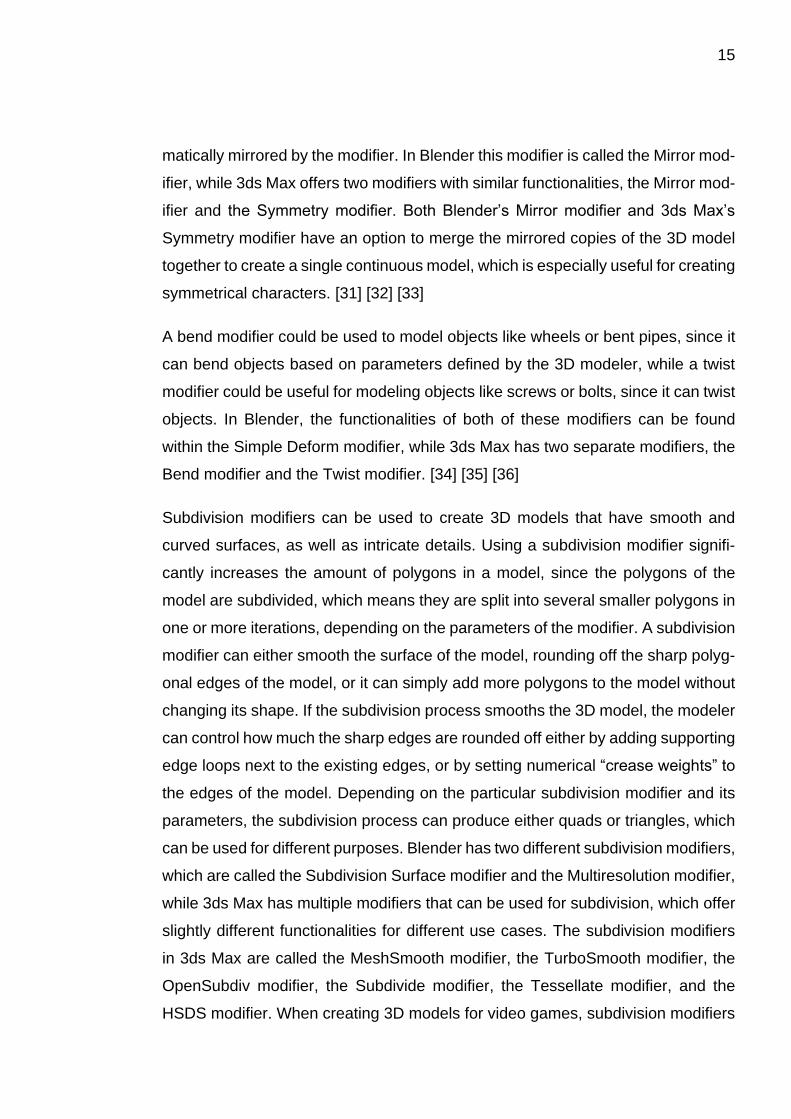
Subdivision modifiers can be used to create 3D models that have smooth and
curved surfaces, as well as intricate details. Using a subdivision modifier signifi-
cantly increases the amount of polygons in a model, since the polygons of the
model are subdivided, which means they are split into several smaller polygons in
one or more iterations, depending on the parameters of the modifier. A subdivision
modifier can either smooth the surface of the model, rounding off the sharp polyg-
onal edges of the model, or it can simply add more polygons to the model without
changing its shape. If the subdivision process smooths the 3D model, the modeler
can control how much the sharp edges are rounded off either by adding supporting
edge loops next to the existing edges, or by setting numerical “crease weights” to
the edges of the model. Depending on the particular subdivision modifier and its
parameters, the subdivision process can produce either quads or triangles, which
can be used for different purposes. Blender has two different subdivision modifiers,
which are called the Subdivision Surface modifier and the Multiresolution modifier,
while 3ds Max has multiple modifiers that can be used for subdivision, which offer
slightly different functionalities for different use cases. The subdivision modifiers
in 3ds Max are called the MeshSmooth modifier, the TurboSmooth modifier, the
OpenSubdiv modifier, the Subdivide modifier, the Tessellate modifier, and the
HSDS modifier. When creating 3D models for video games, subdivision modifiers
16
are often used to create so-called high poly models, which are smooth and intri-
cately detailed versions of the less detailed models that are used in the game,
which are correspondingly called low poly models. The surface details of the high
poly models can be transferred to the textures of the low poly models in a process
called baking. [37] [38] [39] [40] [41] [42] [43] [44] [45] [46]
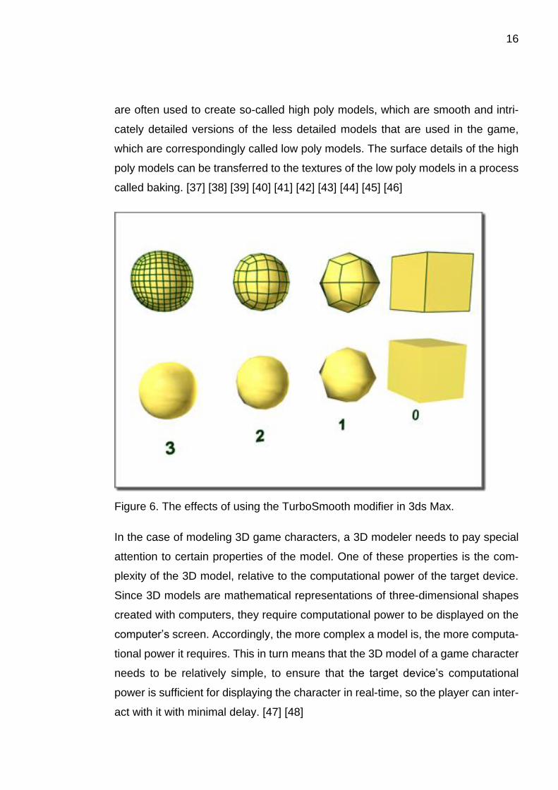
Figure 6. The effects of using the TurboSmooth modifier in 3ds Max.
In the case of modeling 3D game characters, a 3D modeler needs to pay special
attention to certain properties of the model. One of these properties is the com-
plexity of the 3D model, relative to the computational power of the target device.
Since 3D models are mathematical representations of three-dimensional shapes
created with computers, they require computational power to be displayed on the
computer’s screen. Accordingly, the more complex a model is, the more computa-
tional power it requires. This in turn means that the 3D model of a game character
needs to be relatively simple, to ensure that the target device’s computational
power is sufficient for displaying the character in real-time, so the player can inter-
act with it with minimal delay. [47] [48]
17
The complexity of a 3D model depends on a couple of factors, one of the most
important ones being the amount of polygons and vertices the model has. Poly
count is the term used when discussing the amount of polygons in a 3D model. It
refers specifically to the amount of triangles or quads in a model, since a triangle
is the simplest polygon, and a quad is essentially just two triangles joined together.
Consequently, a model with a poly count of 1000 quads has a poly count of 2000
triangles. Poly count can be used to categorize 3D models into so-called high or
low poly models. However, these definitions are highly subjective, since what is
considered high or low poly depends on both the intended use of the 3D model,
as well as how much computational power the current target devices have. Modern
computers and game consoles can easily display hundreds of thousands or even
millions of triangles in real-time, but mobile devices such as smart phones, tablets,
and handheld game consoles are usually more restricted in terms of computational
power. Therefore, a 3D modeler has to keep in mind the technical restrictions of
the target device and use an appropriate amount of polygons when modeling the
3D game character. [48] [49] [50] [51]
Another important property of a 3D model is its topology, which refers to the struc-
ture and distribution of polygons in a 3D model. Having “good” and “clean” topol-
ogy in a 3D model is important for several reasons. For example, the topology of
a 3D model can determine how predictably it subdivides, and topology can also
be used to control the deformation of a model during animation. However, depend-
ing on the intended use of a 3D model, the requirements for “good” topology are
different. For a 3D model that is going to be subdivided, like a base mesh used for
digital sculpting, as well as 3D models that are going to be used in animated or
live action films, it is advisable to use topology that is based on loops of quads,
and to avoid using triangles and n-gons. These loops of quads should conform to
the shapes and curvatures of the 3D model, such as the muscles and anatomy of
a character. In contrast, when creating 3D models for games it is actually accepta-
ble to use triangles alongside quads, but it is good practice to use them sparingly.
Using n-gons, however, should be avoided. [52] [53] [54] [55] [56]

18
The way polygons are distributed across the 3D model of a game character is also
important. More polygons should be placed in areas that are going to deform dur-
ing animation, such as the joints and the face of the character, but using triangles
in these areas should be avoided. This makes it possible to create more natural
looking animations, since the animators have more control over the deformation
of the 3D model, allowing them to create detailed facial expressions, as well as
making sure the character’s limbs retain their shape while bending, instead of col-
lapsing in on themselves like bent straws. [52] [54] [57] [58] [59]
Figure 7. Limb deformation tips by Ben Mathis. Adapted by author.
3.1.3 UV mapping
The 3D modeling process gives the game character its three-dimensional shape,
but in addition to being shaped like the character, the model’s surface usually
needs some color information and material definition, so the character will not ap-
pear to be just a silhouette or a non-defined blob, but instead has distinct features
like skin, hair, and clothing. These details are usually added to the model in a

19
process called texturing, where images called textures are applied onto the sur-
face of the 3D model. However, since the computer has no way of knowing how
to apply these images, which are inherently two-dimensional, over a three-dimen-
sional shape, the polygons of the 3D model need to be mapped onto a two-dimen-
sional surface that matches the images. [60]
UV mapping, or UV unwrapping, is the process of mapping the polygons of a 3D
model onto a two-dimensional surface, so it can be textured. This surface onto
which the polygons are mapped is called a UV map. The “U” and “V” refer to the
coordinate axes of the two-dimensional plane, since “X”, “Y”, and “Z” are used to
refer to the coordinate axes of the three-dimensional space. Each polygon, edge,
and vertex of the 3D model is represented on the UV map, and their location on
the UV map is stored into the UV coordinates of the vertices of the 3D model.
When a texture is applied to the 3D model using the UV map, the parts of the
texture that align with the polygons in the UV map, appear on the corresponding
polygons on the surface of the 3D model. The UV map can also be simply referred
to as the “UVs”. [61] [62] [63]
There are many different ways to map the polygons of a 3D model onto the UV
map. For example, the 3D model can be mapped using different kind of projec-
tions, such as projecting the polygons of the model onto the surface of a plane, a
sphere, a cube or a cylinder. That projection can then be unfolded and flattened
onto the UV map, which in the case of a spherical projection could happen similarly
how the Earth’s surface is projected onto a world map. UV mapping using these
projections can be useful for simple 3D models that resemble these shapes, but
when used with more complex 3D models, these projections often create UV maps
where the polygons of the model are severely distorted or overlapping each other.
Distorted polygons in a UV map can make the textures appear stretched on the
surface of the 3D model, and polygons that are overlapping each other in the UV
map will have the same part of the texture applied to them, which may be unde-
sired. Therefore, for more complex 3D models such as game characters, it is usu-
ally advisable to manually unwrap the surface of the model, hence the name UV
unwrapping. [62] [64] [65] [66] [67]
20
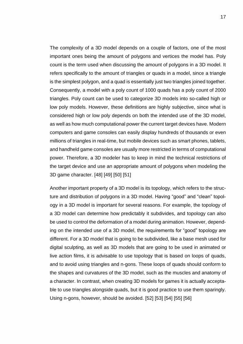
Figure 8. Example of a spherical UV projection in Blender.
Manual UV unwrapping could be compared to peeling an orange or skinning an
animal – the skin is first cut open, and then peeled off, after which it can be flat-
tened by stretching it a bit. Like making cuts into the skin of an animal, seams are
defined along the edges between the polygons of the 3D model. The surface of
the 3D model is then unwrapped into the UV map based on the seams. Sometimes
the seams need to be adjusted or more seams need to be added to make sure the
whole model can be flattened properly, to avoid unwanted stretching and overlap-
ping of the polygons. [62]
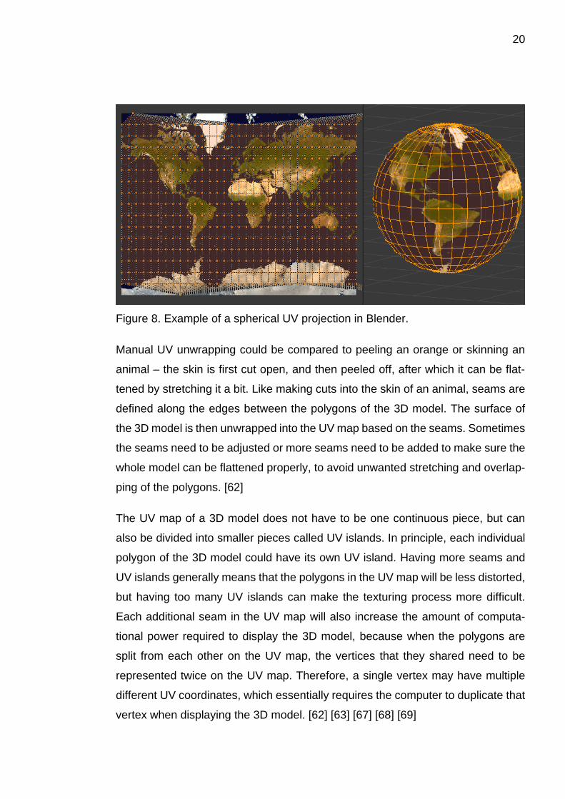
The UV map of a 3D model does not have to be one continuous piece, but can
also be divided into smaller pieces called UV islands. In principle, each individual
polygon of the 3D model could have its own UV island. Having more seams and
UV islands generally means that the polygons in the UV map will be less distorted,
but having too many UV islands can make the texturing process more difficult.
Each additional seam in the UV map will also increase the amount of computa-
tional power required to display the 3D model, because when the polygons are
split from each other on the UV map, the vertices that they shared need to be
represented twice on the UV map. Therefore, a single vertex may have multiple
different UV coordinates, which essentially requires the computer to duplicate that
vertex when displaying the 3D model. [62] [63] [67] [68] [69]
21
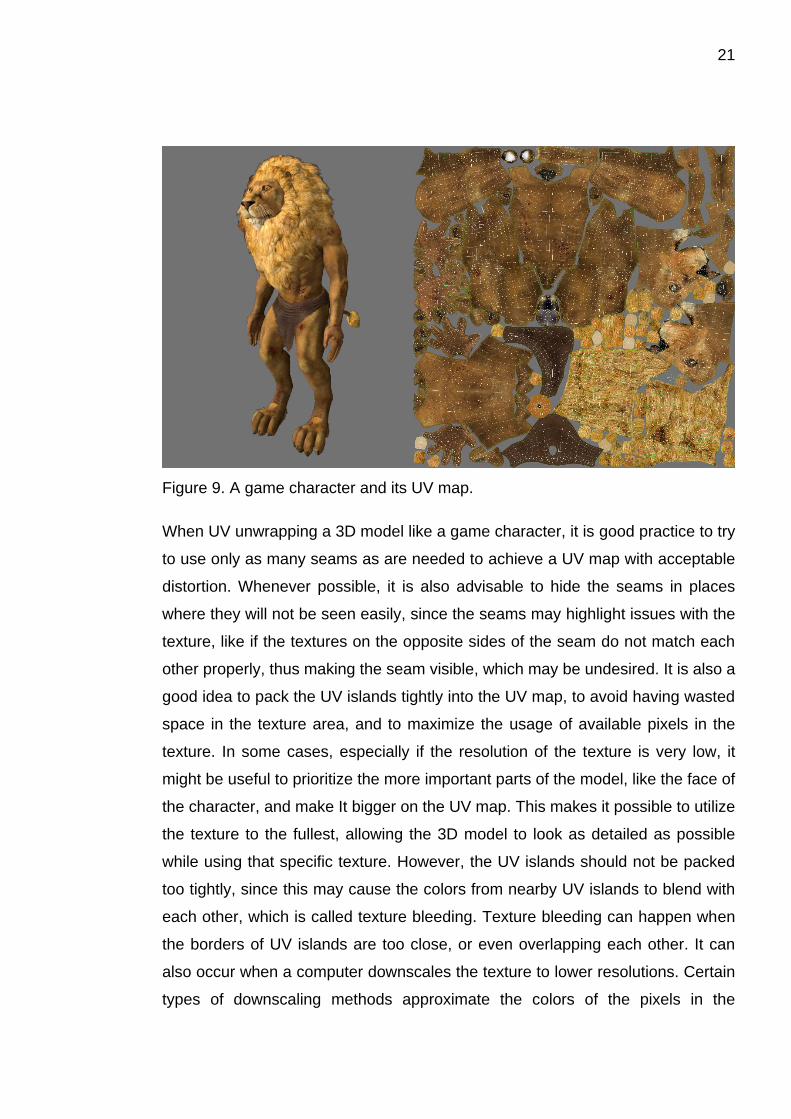
Figure 9. A game character and its UV map.
When UV unwrapping a 3D model like a game character, it is good practice to try
to use only as many seams as are needed to achieve a UV map with acceptable
distortion. Whenever possible, it is also advisable to hide the seams in places
where they will not be seen easily, since the seams may highlight issues with the
texture, like if the textures on the opposite sides of the seam do not match each
other properly, thus making the seam visible, which may be undesired. It is also a
good idea to pack the UV islands tightly into the UV map, to avoid having wasted
space in the texture area, and to maximize the usage of available pixels in the
texture. In some cases, especially if the resolution of the texture is very low, it
might be useful to prioritize the more important parts of the model, like the face of
the character, and make It bigger on the UV map. This makes it possible to utilize
the texture to the fullest, allowing the 3D model to look as detailed as possible
while using that specific texture. However, the UV islands should not be packed
too tightly, since this may cause the colors from nearby UV islands to blend with
each other, which is called texture bleeding. Texture bleeding can happen when
the borders of UV islands are too close, or even overlapping each other. It can
also occur when a computer downscales the texture to lower resolutions. Certain
types of downscaling methods approximate the colors of the pixels in the

22
downscaled texture based on the pixels of the original texture, essentially blending
the original colors. As a result of texture bleeding, the seams on the surface of the
3D model can become visible if the bleeding colors are different from the ones in
the UV island. To prevent texture bleeding, the UV islands should have some
space between them, to allow for texture padding, which means expanding the
desired texture past the borders of the UV island. [62] [68] [70]
Figure 10. The dark line splitting the car’s roof is caused by texture bleeding.
There are also tools and programs that attempt to automatically UV unwrap a 3D
model, or pack the UV map effectively to maximize the use of texture space. Tools
like these can be found in many popular 3D modeling programs, but there are also
several programs and plugins dedicated specifically for these tasks, such as Road-
kill, TexTools, iPackThat, UVLayout, and Unwrella. Using these tools can greatly
reduce the time needed to UV map a 3D model, but they usually still require some
input from the user, and the results often require some manual tweaking, espe-
cially for game assets which need to be optimized. [67] [71] [72] [73] [74] [75] [76]
23
3.1.4 Texturing
Once the character has been UV mapped, it is ready for texturing. As previously
mentioned, textures, which are sometimes called maps or skins, are images that
are applied onto the surface of a 3D model, and the process of creating those
images is called texturing. Textures can be created in a variety of ways. They can
be hand painted by using a digital painting program, or they can be painted directly
onto the 3D model by using a 3D painting program. Photos can be used as textures
by using photo-manipulation to combine different images together and to tweak
their colors, as well as to align them with the UV map. Textures can also be created
procedurally using parameters that are defined by the artist, and they can be de-
rived from other 3D models in a process called baking. There are several different
types of textures used for different purposes, and they can be used in different
combinations to achieve different effects. The most commonly used texture types
are different color maps. Other commonly used texture types are different kinds of
specular maps and bump maps, as well as transparency maps, also known as
opacity maps. There are also different texture types that affect the way a 3D model
is lit, such as ambient occlusion maps, cavity maps, and emissive maps. [77] [78]
Color maps define the surface color of the 3D model, or in more technical terms,
the diffuse reflection of light from the surface. In traditional texturing workflows
these maps are called diffuse maps, but when creating textures for physically
based rendering, their equivalents are called albedo maps. The concept of physi-
cally based rendering will be discussed in more detail in the following chapters.
The diffuse map can sometimes be the only texture used in a 3D model, and can
therefore contain lighting information such as highlights and shadows, as well as
different material definitions like metal and wood. In contrast, the albedo map is
usually used with several other maps and should only contain the base color of
the material, with as little lighting information as possible, and the brightness of the
color should be consistent with the diffuse reflectivity of the corresponding real-
world material. [78] [79] [80] [81]
24
Different kinds of specular maps control how reflective or glossy the surface of the
model appears. Just like with color maps, different workflows use different specu-
lar maps. Basic specular maps used with traditional workflows usually control only
the brightness of the specular reflections, but if the specular map is colored, it can
also change the tint of the reflections, which is useful for creating metallic surfaces.
Gloss maps control how glossy or matte the surface of the model appears, and
are often used together with specular maps. In physically based rendering work-
flows the equivalent material properties are controlled with roughness maps, re-
flectivity maps, and metallic maps. [78] [82] [83]
Bump maps are textures that change how the 3D model is shaded, which means
they can be used to create an illusion that the surface of the model has more detail
than there actually is in the model’s geometry. The most basic bump maps are
grayscale textures, where areas that are lighter color appear to come outwards
from the surface of the model, and areas of darker color appear to sink into the
model. Normal maps are similar to basic bump maps, but are more advanced,
since instead of storing simple one-directional height information, they modify the
direction of the model’s surface normals, which allows for more complex surface
detail to be depicted. This makes it possible to store the surface detail of a high
poly model into the normal map of a low poly model in a process called baking. By
using baked normal maps, a low poly 3D model can appear almost as detailed as
a high poly 3D model, while requiring only a fraction of the computational power
needed to display the high poly model. [60] [78] [84] [85] [86]

25
Figure 11. A game character with and without a baked normal map.
Height maps, often also referred to as displacement maps, are similar to bump
maps. Like basic bump maps, height maps are grayscale textures that represent
the height difference from the model’s surface as areas of lighter and darker col-
ors. However, instead of using the textures to create an illusion of height, the maps
are used to displace the vertices of the model, which means the model’s shape is
modified based on the height map. When this is combined with dynamic tessella-
tion, which means subdividing the polygons of the model in real-time, the surface
of the model can become extremely detailed. Dynamic tessellation can be linked
to the viewing distance, which allows for having very detailed models when viewing
up close, while having less detailed models in the distance. Height maps can also
be used for other effects, such as parallax mapping, which is another technique
used to create an illusion of depth in a texture. There are several different versions
of parallax mapping, but they all work by moving around the pixels of the other
textures of the model in real-time, based on the height map and the viewing angle.
This creates the effect of the texture changing along shifts in perspective, which
can create the illusion of depth. [78] [84] [87] [88] [89] [90] [91]
26
Transparency maps define which parts of the model are either partly or completely
transparent. They can be used to create objects like windows, but can also be
used to cut out parts of a surface, which allows for creating things like tree leaves,
grass, and hair without needing to model complex details, by using simple flat
planes of polygons with partly transparent textures. Transparency maps can
sometimes be stored in other textures like diffuse or normal maps, but can also be
separate textures, in which case they are either grayscale textures or black-and-
white masks. [78] [92] [93]
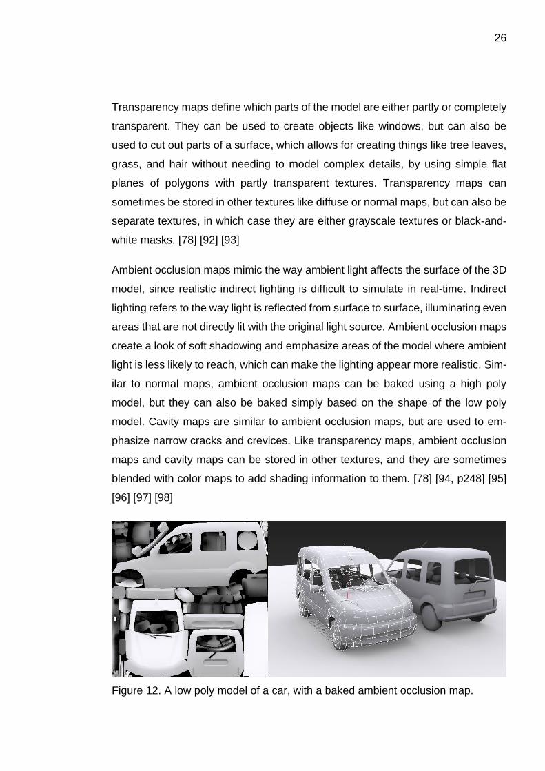
Ambient occlusion maps mimic the way ambient light affects the surface of the 3D
model, since realistic indirect lighting is difficult to simulate in real-time. Indirect
lighting refers to the way light is reflected from surface to surface, illuminating even
areas that are not directly lit with the original light source. Ambient occlusion maps
create a look of soft shadowing and emphasize areas of the model where ambient
light is less likely to reach, which can make the lighting appear more realistic. Sim-
ilar to normal maps, ambient occlusion maps can be baked using a high poly
model, but they can also be baked simply based on the shape of the low poly
model. Cavity maps are similar to ambient occlusion maps, but are used to em-
phasize narrow cracks and crevices. Like transparency maps, ambient occlusion
maps and cavity maps can be stored in other textures, and they are sometimes
blended with color maps to add shading information to them. [78] [94, p248] [95]
[96] [97] [98]
Figure 12. A low poly model of a car, with a baked ambient occlusion map.
27
Emissive maps create an effect that makes the texture of the model appear as if it
is emitting light. However, the texture does not actually function as a light source,
so it cannot be used for lighting purposes, unless the game engine is specifically
instructed to consider the emissive textures as light sources. Emissive maps are
useful for creating objects such as glowing computer monitors, burning coal or
magical items. [78] [99] [100]
In addition to the aforementioned texture types, there are also several other texture
types that are sometimes used alongside the more common textures. For exam-
ple, so-called detail maps can be used to add small scale details to 3D models.
Detail maps are tiling textures, which means that the textures are repeated infi-
nitely in one or more directions to cover large areas with sufficient detail. Detail
maps are blended together with the primary textures, which makes it possible to
create very detailed surfaces without having to use high resolution textures, where
all the detail would have to be in the primary textures. Additionally, some material
properties cannot be convincingly conveyed by using only the more common tex-
ture types, and as a result there are multiple texture types that are used for very
specific purposes, such as creating realistic looking skin, hair, and velvet, or for
creating effects like flowing liquids. [78] [101] [102] [103]
There are various different workflows that can be used for creating textures for a
3D model of a game character, and which of those are used for a specific model
depends on several things, such as the artistic style of the game, the requirements
of the game engine, the technical limitations of the target device, and the prefer-
ences of the texture artist, as well as what software and tools are available at the
game studio. It is common to start the texturing by creating the color map, since it
is the most commonly used texture type. The color map is traditionally created in
a program like Adobe Photoshop, where the texture can be either hand painted
using the UV map as a guide, or it can be created out of photographs using the
program’s photo-manipulation tools. However, nowadays there are also programs
that allow the texture artist to paint or project photographs directly onto the surface
of the 3D model, which means the artist does not have to guess how the texture
28
they are creating will appear on the surface of the model, since it is immediately
visible as they are working on it. [104, p86] [105] [106]
One way to approach the creation of the color map is to first separate areas of
different materials by covering them with different base colors that match the color
of the intended material. The base color can then be overlaid with more detail and
color variation to better express the look of the material. Once the material has
been properly defined, it is possible to add some weathering and wear to the tex-
ture, such as dust, grime, rust, and dirt, as well as scratches, scuff marks, and
edge wear. [107, p48-62] [107, p278] [108, p124-128] [108, p206-215]
Another approach to the creation of the color map is to start the texturing by com-
bining photographs of different materials into the texture. These photographs are
then photo-manipulated to align with the UV map of the model, and color corrected
to remove differences in lighting between different photographs. The aim is to
achieve a sort of neutral lighting, so the textures will look good in all lighting con-
ditions within the game. [107, p273-275]
After the color map has been created, it can be complemented with other maps
that add material definition to the model, such as specular maps or bump maps.
Sometimes the other maps can be created by modifying the original color map, or
generated from it using special software, such as CrazyBump, AwesomeBump or
Bitmap2Material. [107, p95] [108, p216] [109] [110] [111]
If the color map is the only map that will be used with the 3D model, the texture
artist can attempt to imitate the effects of the other maps by creating fake highlights
and shading into the color map, and by using different types of shading for different
materials to better distinguish them from each other. Ambient occlusion maps and
other baked lighting information can also be blended with the color map to achieve
more realistic shading. [97] [107, p50-59] [107, p90-92] [107, p123-125] [112, p28-
29]
If a high poly version of the 3D model was created during the 3D modeling process,
it can be used to create textures for the low poly 3D model, by baking the details
29
of the high poly model into the textures of the low poly model. It is common to bake
textures like normal maps and ambient occlusion maps from the high poly model,
but sometimes even textures like color maps and specular maps can be baked, if
the high poly model has had materials and textures applied onto it. This can be
useful for workflows where the high poly model is made first, and the low poly
model is created from the high poly model using a method called retopoligizing.
[107, p180] [107, p108] [107, p270] [108, p123-126] [112, p28-29] [113] [114] [115]
When creating textures for games, texture artists need to take into consideration
how the textures will affect the performance of the game. Textures contain data
which the target device needs to store and process, and the amount of data in-
creases as there are more textures, or if the textures are large in terms of how
many pixels they have. It is advisable to use only as many, and only as large tex-
tures as are needed to make the game look good, while still maintaining good
performance. Using more and larger textures with more pixels in them can lead to
bad performance, since they require more computational power, memory, and
storage space.
Texture artists should also pay attention to what the dimensions of the textures
are. To make sure the textures are as efficient as possible in terms of game per-
formance, their dimensions, measured in pixels, should conform to the so-called
“Power of Two” rule, sometimes abbreviated as PoT. The PoT rule dictates that
both the horizontal and vertical resolutions of a texture should be in powers of two,
which are exponentiations of the number two. For example, a texture could be 16
pixels wide and 2 pixels high, or 1024 pixels wide and 256 pixels high, but a texture
that was 1500 pixels wide and 2000 pixels high would not follow the PoT rule.
Modern games also have a preference for textures that are either square, or rec-
tangular with two-to-one dimensions, like a texture with a width and height of 512
pixels, or a texture that is 4096 pixels wide and 2048 pixels high. The PoT rule is
used because game engines and computers manage and process data in
“chunks” of certain sizes, rather than all at once, and textures that conform to the
PoT rule are optimized for that process. That said, textures that do not follow the
30
PoT rule can usually still be used in games, but using them will be less efficient
and can negatively affect the performance of the game. [116]
The so-called working size is another thing to consider while creating textures for
games. Working size refers to the size in which the textures are initially created,
in comparison to the size they are going to be used in the game. In some cases,
it can be useful to create the textures larger than the size in which they will appear
in the game, and then downscale them for the game. This makes it possible to use
the original working size textures if there happens to be a need to use higher res-
olution textures, which means the textures do not have to be remade for that pur-
pose. Of course, if the working size of the textures is larger than the size in which
they appear in the game, the texture artists need to take into consideration the
amount and size of the details they create into the textures, since details that are
too small might not be properly depicted in the downscaled textures. [108, p55-56]
[117, p50-51] [118]
3.1.5 Rigging
Before a complex 3D model like a game character can be animated, the model
needs to be rigged. Rigging is the process of creating a rig, which is a system of
digital bones, joints, and other controls which are bound to the 3D model, and
which the animators can use to move and bend the model to create animations.
The complexity of the rig depends on how the character is supposed to be ani-
mated, and what the technical limitations of the target device are. A rig for simple
posing and movement can be created in a few hours, but for achieving more de-
tailed animations like nuanced facial expressions, a more complex rig is needed,
which may require days or weeks of work from a professional rigger. [119] [120]
A basic character rig would consist of a so-called “skeleton” which is a system of
digital bones and joints. The terms “joint” and “bone” are sometimes used inter-
changeably, since different software use different naming conventions and slightly
different rigging techniques. However, a simple explanation of the terms would be

31
that joints are the actual articulation points of the rig, and bones are the connec-
tions between different joints. So, bones represent the direct connections each
joint has to other joints, but not every joint is connected to every other joint directly.
Some rigging tools, like the 3ds Max Character Animation Toolkit, have visual rep-
resentations for bones, whereas they have no visual representations for joints,
which are simply the points where the bones are connected to each other. [120]
[121] [122]
Figure 13. A low poly game character and its rig, highlighted in white.
The rig follows a logical hierarchy. The highest component in the hierarchy of the
skeleton is called the root joint or root bone, to which each subsequent joint and
bone is connected to, either directly, or indirectly through other joints and bones.
The hierarchy makes it possible to create a system where the rotation of a joint
affects every joint that is lower in the hierarchy, so that they follow the movement.
For example, rotating a character’s shoulder joint would rotate the whole arm. This
kind of rig is called an FK, or Forward Kinematics rig. Sometimes it is useful to
have the rig function in the opposite way, so that the joints lower in the hierarchy
affect the joints above. For example, an animator might want to place the charac-
ter’s palms or feet to specific locations, and have the rest of the arms and legs
move into appropriate positions. A rig that allows for this kind of functionality is
called an IK, or Inverse Kinematics rig. An IK rig automatically interpolates the
32
positions of the other joints in the rig based on where the joints lower in the hier-
archy are placed. This can speed up the animating process, since the animator
does not have to adjust each and every joint in the rig manually to get the last
joints into the correct positions. However, since the positions of the other joints are
interpolated automatically, the animator may have to correct some of the joints if
they are not pleased with the results of the interpolation. [119] [120]
In addition to creating a rig with IK and FK controls, a rigger can utilize so-called
driven keys. Driven keys allow the animator to “drive” different functions of the rig
with simple controls. A driven key consists of a driver and the driven. For example,
the function driven by the driven key could be closing and opening the fist of a
character, and the driver controlling that function could be a numerical value, an
attribute of another 3D object, or a slider in the user interface of the animation
software. Using a driven key can significantly speed up the animating process,
since the animator can use a single control to drive complex actions that involve
multiple joints in different positions, instead of having to manually position each of
those joints every time they want to perform those actions. [120] [123] [124]
A basic rig consisting of joints and bones is suitable for simple posing and body
movements, but for nuanced facial expressions, a separate facial rig is needed. A
facial rig could be a combination of blend shapes and other deformers, as well as
joints and bones. While joints and bones can be used for some facial movements,
like moving the jaw bone, they do not work very well for subtler facial expressions,
which require very stretchy and organic motion. Instead of bones and joints, de-
formers such as blend shapes can be used to achieve these more detailed move-
ments. [120] [119] [125, p379-380] [126] [127]
Blend shapes, sometimes referred to as morph targets, are versions of the 3D
model in which the vertices of the model have been moved from their neutral po-
sition to achieve a certain shape, such as a facial expression. Blend shapes are
linked to the original model, and their effect on the model can be blended on or off,
similar to using driven keys. For example, a variation of a character model could
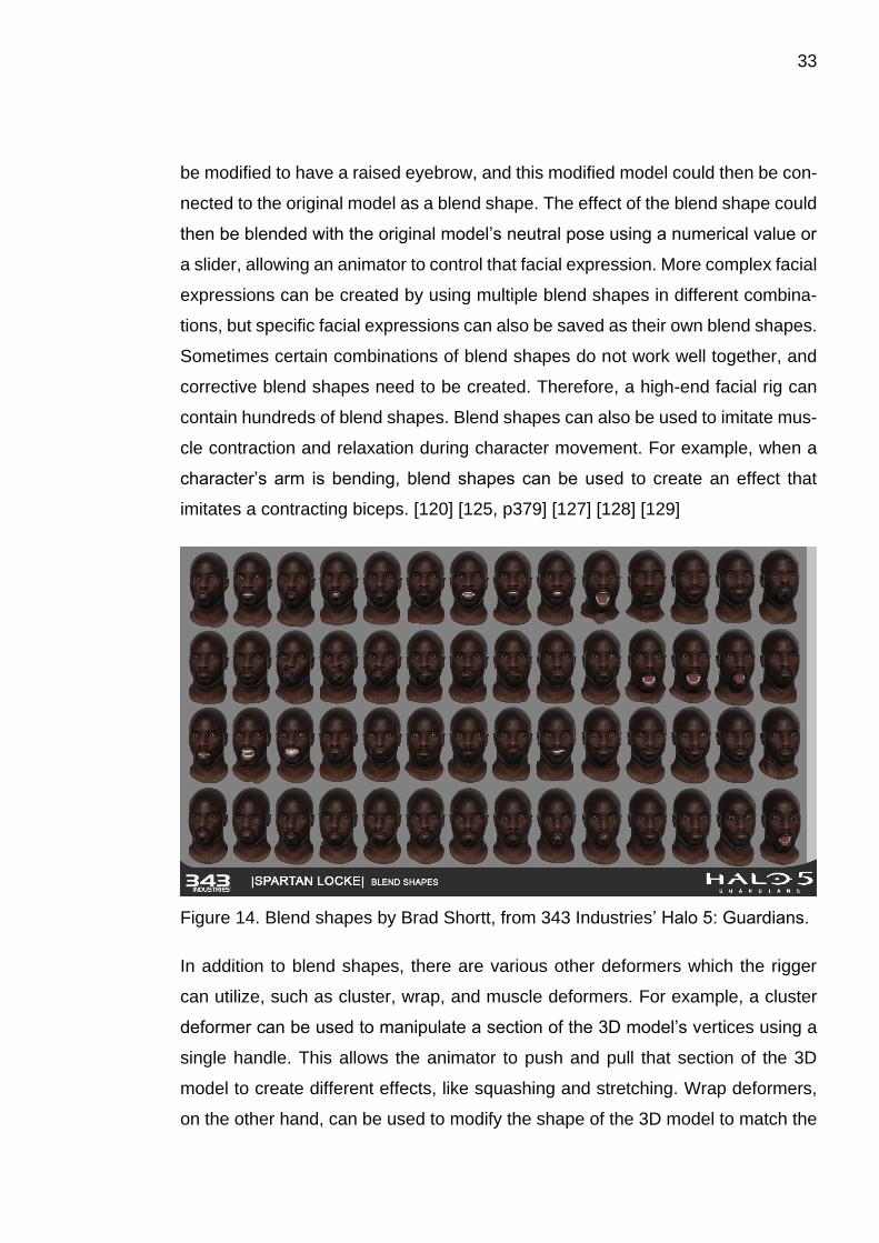
33
be modified to have a raised eyebrow, and this modified model could then be con-
nected to the original model as a blend shape. The effect of the blend shape could
then be blended with the original model’s neutral pose using a numerical value or
a slider, allowing an animator to control that facial expression. More complex facial
expressions can be created by using multiple blend shapes in different combina-
tions, but specific facial expressions can also be saved as their own blend shapes.
Sometimes certain combinations of blend shapes do not work well together, and
corrective blend shapes need to be created. Therefore, a high-end facial rig can
contain hundreds of blend shapes. Blend shapes can also be used to imitate mus-
cle contraction and relaxation during character movement. For example, when a
character’s arm is bending, blend shapes can be used to create an effect that
imitates a contracting biceps. [120] [125, p379] [127] [128] [129]
Figure 14. Blend shapes by Brad Shortt, from 343 Industries’ Halo 5: Guardians.
In addition to blend shapes, there are various other deformers which the rigger
can utilize, such as cluster, wrap, and muscle deformers. For example, a cluster
deformer can be used to manipulate a section of the 3D model’s vertices using a
single handle. This allows the animator to push and pull that section of the 3D
model to create different effects, like squashing and stretching. Wrap deformers,
on the other hand, can be used to modify the shape of the 3D model to match the
34
shape of another 3D model. For example, a wrap deformer with a cone-shaped
3D model could be used to create an animation of a spike growing on the head of
a character. Muscle deformers are slightly more complex than cluster or wrap de-
formers, since they simulate the effects of muscles contracting and relaxing, as
well as the effect of skin sliding over the muscles. In some rigging tools, muscle
deformers can also be used to simulate the jiggle of muscles during fast move-
ments, as well as the collisions between different muscles and body parts. How-
ever, muscle deformers tend to be computationally heavy, and are not usually
used in games. Even fairly recent high end games, such as Crytek’s Ryse: Son of
Rome, still use joint and blend shape based rigs instead of muscle deformers.
[130] [131] [132] [133] [134] [135, p9-10, 95-105] [136, p13] [137] [138]
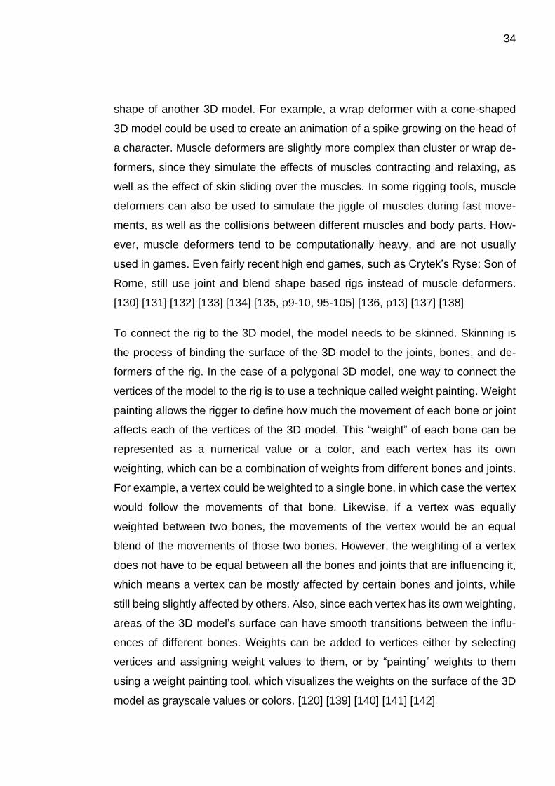
To connect the rig to the 3D model, the model needs to be skinned. Skinning is
the process of binding the surface of the 3D model to the joints, bones, and de-
formers of the rig. In the case of a polygonal 3D model, one way to connect the
vertices of the model to the rig is to use a technique called weight painting. Weight
painting allows the rigger to define how much the movement of each bone or joint
affects each of the vertices of the 3D model. This “weight” of each bone can be
represented as a numerical value or a color, and each vertex has its own
weighting, which can be a combination of weights from different bones and joints.
For example, a vertex could be weighted to a single bone, in which case the vertex
would follow the movements of that bone. Likewise, if a vertex was equally
weighted between two bones, the movements of the vertex would be an equal
blend of the movements of those two bones. However, the weighting of a vertex
does not have to be equal between all the bones and joints that are influencing it,
which means a vertex can be mostly affected by certain bones and joints, while
still being slightly affected by others. Also, since each vertex has its own weighting,
areas of the 3D model’s surface can have smooth transitions between the influ-
ences of different bones. Weights can be added to vertices either by selecting
vertices and assigning weight values to them, or by “painting” weights to them
using a weight painting tool, which visualizes the weights on the surface of the 3D
model as grayscale values or colors. [120] [139] [140] [141] [142]
35
Figure 15. Weight painting a game character in 3ds Max.
There are a couple of things a rigger can do to make animating the rig easier for
animators. For example, the rigger can create controls and handles which the an-
imators can use to animate the rig, since the actual rig is usually hidden inside the
3D model to which it is bound to. These controls and handles are often simply
called controls or control curves, but in the 3ds Max Character Animation Toolkit
they are called manipulation gizmos. In addition to creating handles which the an-
imators can use to grab and manipulate the rig, a rigger can also use driven keys
to create a simple interface for animating more complex functions of the rig, such
as blending between different blend shapes. Another thing a rigger can implement
to the rig is to add rotation and movement constraints to the joints and bones. For
example, a human character’s knees and elbows should only be able to rotate on
one axis, and should not be able to rotate past the point where the limb is straight.
However, while creating these constraints, the rigger needs to take into consider-
ation that the animators might want to deliberately “break” the rig to create exag-
gerated movements. [120] [119] [124] [143] [144] [145]
While complex rigs such as facial rigs or muscle rigs often need to be hand crafted
by a dedicated rigger, many rigging tools allow the rigger to partially automate the
36
rigging process, and there are even specific plugins, programs, and online ser-
vices which can rig characters almost completely automatically. For example, 3ds
Max Character Animation Toolkit creates both IK and FK systems automatically
for each limb that is created, and speeds up the rigging process by allowing the
rigger to simply input the amount of limbs, bones, and digits in each body part,
without needing to manually create the skeleton. Many 3D software, such as Au-
todesk Maya, Autodesk 3ds Max, and Blender, also have either built in tools or
plugins that can automate most of the rigging process, such as Maya’s Quick Rig
Tool, the Anzovin Rig Tools plugin for Maya, the LH Auto-Rig plugin for 3ds Max,
and the Auto-Rig Pro plugin for Blender. In addition, Mixamo offers similar func-
tionality as an online service, called Auto-Rigger. Automating the rigging process
either partially or entirely can significantly speed up the production of game char-
acters, and is especially useful for small game studios which may not have dedi-
cated riggers. [146] [147] [148] [149] [150] [151]
3.1.6 Animation
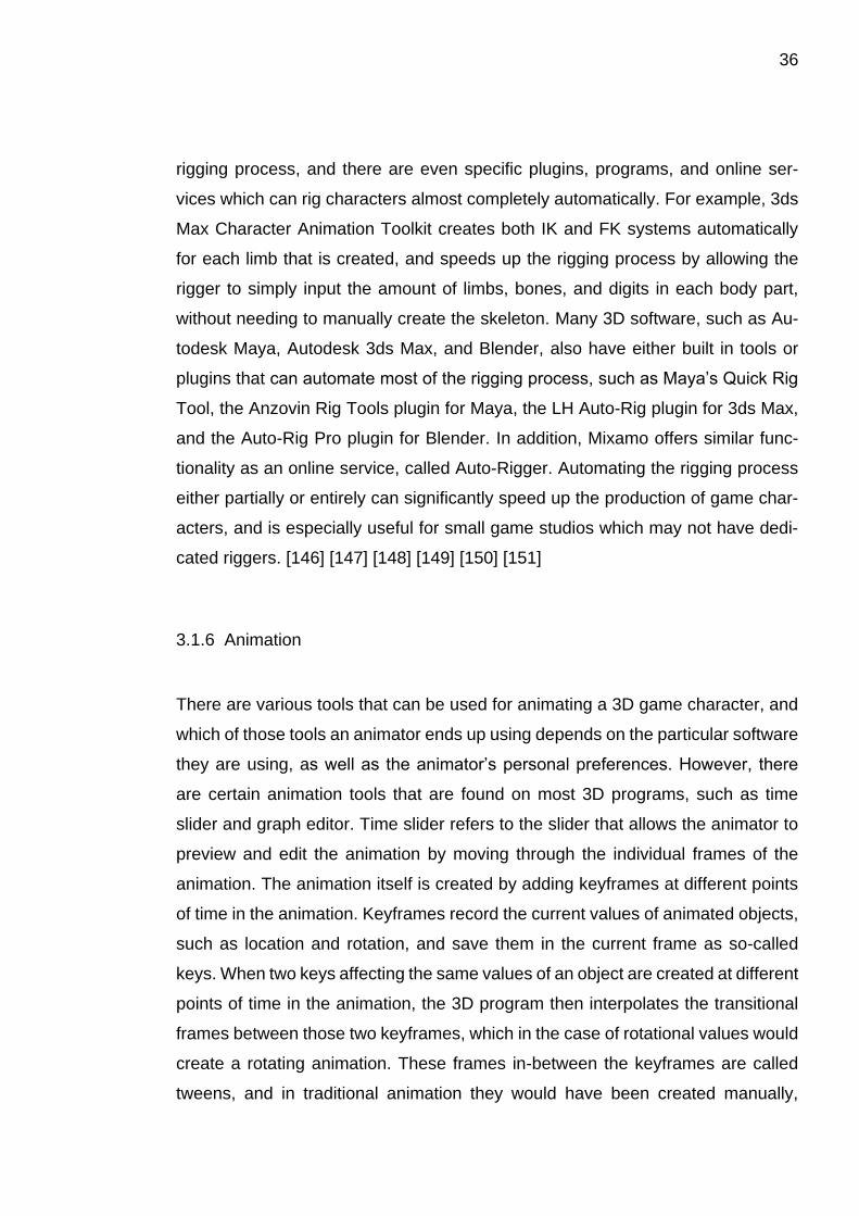
There are various tools that can be used for animating a 3D game character, and
which of those tools an animator ends up using depends on the particular software
they are using, as well as the animator’s personal preferences. However, there
are certain animation tools that are found on most 3D programs, such as time
slider and graph editor. Time slider refers to the slider that allows the animator to
preview and edit the animation by moving through the individual frames of the
animation. The animation itself is created by adding keyframes at different points
of time in the animation. Keyframes record the current values of animated objects,
such as location and rotation, and save them in the current frame as so-called
keys. When two keys affecting the same values of an object are created at different
points of time in the animation, the 3D program then interpolates the transitional
frames between those two keyframes, which in the case of rotational values would
create a rotating animation. These frames in-between the keyframes are called
tweens, and in traditional animation they would have been created manually,
37
whereas in 3D animation the program creates them automatically. If the animator
is not pleased with the speed of the animation, they can simply move the keys
from one frame to another, making the animation faster or slower. For more pre-
cise control over the animation, the animator can use the graph editor. Graph ed-
itor allows the animator to edit the so-called animation curves between different
keys. Animation curves are visual representations of the way the 3D program in-
terpolates the transition from one key value to another. The values of the keys can
be seen on a graph, where they are visualized at different vertical positions de-
pending on their numerical values, and at different horizontal positions depending
on the points in time they are keyed at. The keys affecting the same value are
connected with lines called curves, which represent the interpolation between
those keys. The curves can be edited to achieve different effects for the animation.
For example, a straight line between two location keys would mean that the inter-
polation between them would be linear, which would result in a movement that has
constant velocity. However, if the line between the keys was curved, it would result
in an accelerating or decelerating movement. [152] [153] [154] [155]
Figure 16. Time slider, keyframes, and animation curves in 3ds Max.
Animators have a lot of different techniques at their disposal when animating a
game character. They can use skeletal animation, which refers to animating using
a rig consisting of bones and joints, and they can complement the skeletal anima-
tion with deformers and blend shape animation if the rig supports them. They can
also use vertex animation, which refers to animating vertices of a model without
38
using joints or deformers. Vertex animation can be used for animating complex
motions like simulated cloth, hair, or water movement. Cloth and hair simulations
can be simulated in the animation software, and then imported into the game as
vertex animations, or they can be baked into joints and bones, if the character’s
clothes and hair have been rigged. The simulations can also be performed within
the game, but this is sometimes too computationally intensive. However, simulated
cloth and hair movement can be approximated within a game using procedural
vertex animation that relies on movement based on sine waves or interpolated
triangle waves. [156] [157] [158] [159] [160] [161] [162]
Animators can also use textures for animating a game character. UV panning
means animating the UV coordinates of a texture, which creates an effect of the
texture moving. Combining this with a tiling texture can create a seamlessly loop-
ing animation, which can be useful for creating effects like flowing water. Textures
can also be used for animation by creating a texture that is a combination of mul-
tiple frames of traditional animation, called a spritesheet. The spritesheet can then
be animated on the surface of a 3D model by switching between different frames
of the animation using a technique similar to UV panning. This kind of texture ani-
mation can be used for creating facial animations on stylized low poly characters,
for example. Wrinkle maps are another way to use textures for animation. Wrinkle
maps are normal maps or displacement maps that contain depth information of
wrinkles that are caused by different poses, such as stretched or compressed fa-
cial expressions, like a wrinkled forehead or squinting eyes. The effect of the wrin-
kle maps is blended with the base normal or displacement maps using masks that
correspond to different poses or expressions, and different areas of the skin. This
way the animator can control which areas of the skin get wrinkled during specific
animations. The effect of the wrinkle maps can also be linked to different blend
shapes or bone and joint positions, which automates the effect. The wrinkle maps
themselves can be created by sculpting the expressions in a digital sculpting pro-
gram, and then baking the expressions into a normal map or a displacement map.
[163] [164] [165] [166] [167] [168] [169]
39
Figure 17. Wrinkle map sculpting for Naughty Dog’s Uncharted 4: A Thief’s End.
Adapted by author.
When creating animations for game characters, animators should always keep in
mind the 12 principles of animation, which are a collection of guidelines and tech-
niques created by Frank Thomas and Ollie Johnston, who were pioneers of ani-
mation at Walt Disney Studios. The 12 principles of animation are: timing and
spacing, slow in and slow out, squash and stretch, follow through and overlapping
action, arcs, anticipation, secondary action, straight ahead and pose to pose, stag-
ing, solid drawing, appeal, and exaggeration. All of these principles apply to game
animation, however, the way they are used may slightly differ from traditional ani-
mation. [170]
Timing and spacing are perhaps the most important principles of animation. Timing
is an animation term that is used to describe how long an action or a movement
takes to complete, or when it begins and ends. The timing of a movement can be
measured in either the amount of frames, or the amount of time it takes to complete
that movement, since the amount of frames there are within any given amount of
time depends on the frame rate of the animation. Frame rate refers to the amount
of frames that are displayed in one second, which is measured in frames per sec-
ond, or FPS. If an animation had a frame rate of 24 FPS, a movement lasting one
second would have 24 frames, but at the frame rate of 60 FPS, it would have 60
frames. Spacing is closely related to timing, but whereas timing refers to the
amount of frames in a movement, spacing describes how the movement pro-
gresses within those frames. For example, if an object was animated to move at a
constant speed, the amount of movement from frame to frame would be equal.

40
However, if the object was animated to accelerate or decelerate, the amount of
movement from frame to frame would either gradually increase or decrease. If
each of these animations had the same amount of frames, they would all still last
the same amount of time, but the movement in each animation would be drastically
different from the others. Timing and spacing are the basic building blocks that
create the illusion of movement in animation. When used correctly, they can make
animations appear believable and realistic, but also appealing and impactful. [154]
[170] [171] [172] [173]
Figure 18. Visualization of timing and spacing.
Slow in and slow out, often also referred to as ease in and ease out, are animation
principles that refer to accelerating and decelerating movement. In the real world,
all movements require time for either acceleration or deceleration. For example, a
stationary car cannot reach its top speed in an instant, but must first accelerate
until the speed is reached. In animation, this gradual transition from stationary to
full speed is called a slow in, and conversely, if the car was braking to a halt from
top speed, this would be referred to as slow out. Of course, these principles can
also be applied to character movements, such as the swinging hands of a walking
character. Whenever the hands change direction while swinging back and forth,
41
they need to slow out to a stop, and then again slow in to the movement in the
opposite direction. In most 3D programs, the slow in and slow out can be observed
in the animation curves within the graph editor, and can be edited to achieve dif-
ferent kinds of effects. In video games, the principles of slow in and slow out are
sometimes also used to blend different animations to create more natural looking
movements. For example, a character could have separate animations for walking
and running, but switching or blending between these two animations might result
in movement that looks unnatural. To fix this issue, a transitional jogging animation
could be created, which, when blended in-between the two existing animations,
would essentially create slow in and slow out effects for the walking and running
animations. [170] [174] [175]
Squash and stretch refers to the way an object’s shape deforms during movement.
For example, a bouncy ball will squash when hitting the ground after a fall, and
conversely, will stretch when bouncing off the ground. An important part of the
effect is that the object retains its volume during the movement. While squashing,
the ball is compressing in height, but also thickening in width, and while stretching,
the ball will get thinner, but also longer. Squash and stretch can also be observed
in the nature and in living beings, like in the facial expressions of people. In ani-
mation the effect can be exaggerated to achieve more appealing movement.
Squash and stretch can also be exaggerated even further to create cartoony and
comical animations. [176]
Follow through and overlapping action could be considered two different, yet
closely related principles. Follow through refers to the way some parts of an object
or a character continue moving after most of the movement has come to a stop.
For example, when a character comes to a stop after running, their hair or clothes
might keep moving forward for a moment, and then bounce back, until eventually
settling. Overlapping action is similar to follow through in the sense that it is related
to different parts of an object or a character moving at different times. However,
whereas follow through is usually related to things that are affected by outside
forces, like clothes that are affected by a character’s movements, overlapping ac-
tion is usually related to the movement of parts within an object or a character that
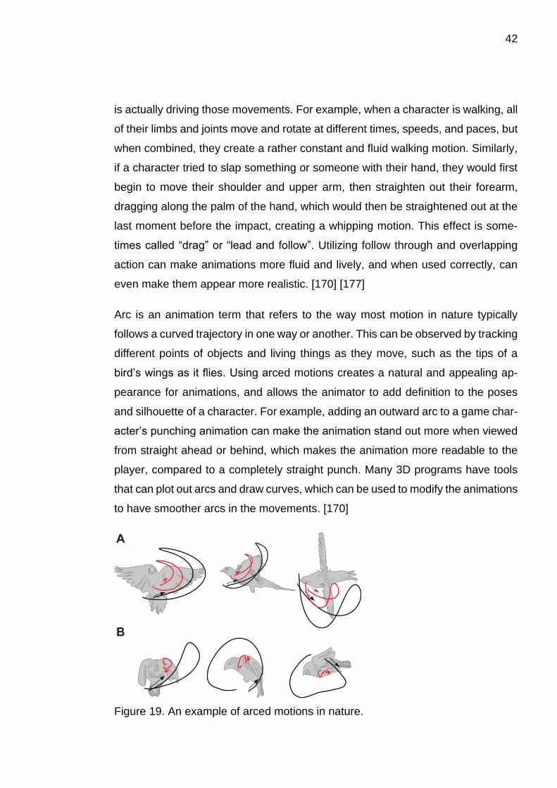
42
is actually driving those movements. For example, when a character is walking, all
of their limbs and joints move and rotate at different times, speeds, and paces, but
when combined, they create a rather constant and fluid walking motion. Similarly,
if a character tried to slap something or someone with their hand, they would first
begin to move their shoulder and upper arm, then straighten out their forearm,
dragging along the palm of the hand, which would then be straightened out at the
last moment before the impact, creating a whipping motion. This effect is some-
times called “drag” or “lead and follow”. Utilizing follow through and overlapping
action can make animations more fluid and lively, and when used correctly, can
even make them appear more realistic. [170] [177]
Arc is an animation term that refers to the way most motion in nature typically
follows a curved trajectory in one way or another. This can be observed by tracking
different points of objects and living things as they move, such as the tips of a
bird’s wings as it flies. Using arced motions creates a natural and appealing ap-
pearance for animations, and allows the animator to add definition to the poses
and silhouette of a character. For example, adding an outward arc to a game char-
acter’s punching animation can make the animation stand out more when viewed
from straight ahead or behind, which makes the animation more readable to the
player, compared to a completely straight punch. Many 3D programs have tools
that can plot out arcs and draw curves, which can be used to modify the animations
to have smoother arcs in the movements. [170]
Figure 19. An example of arced motions in nature.
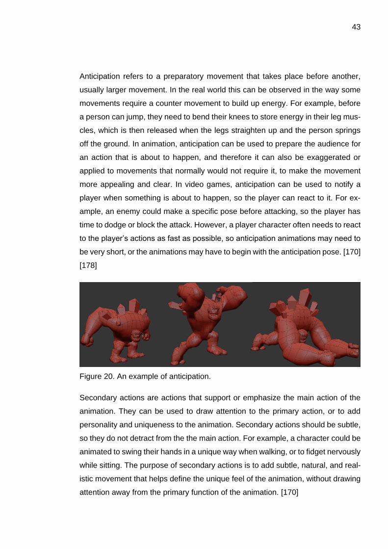
43
Anticipation refers to a preparatory movement that takes place before another,
usually larger movement. In the real world this can be observed in the way some
movements require a counter movement to build up energy. For example, before
a person can jump, they need to bend their knees to store energy in their leg mus-
cles, which is then released when the legs straighten up and the person springs
off the ground. In animation, anticipation can be used to prepare the audience for
an action that is about to happen, and therefore it can also be exaggerated or
applied to movements that normally would not require it, to make the movement
more appealing and clear. In video games, anticipation can be used to notify a
player when something is about to happen, so the player can react to it. For ex-
ample, an enemy could make a specific pose before attacking, so the player has
time to dodge or block the attack. However, a player character often needs to react
to the player’s actions as fast as possible, so anticipation animations may need to
be very short, or the animations may have to begin with the anticipation pose. [170]
[178]
Figure 20. An example of anticipation.
Secondary actions are actions that support or emphasize the main action of the
animation. They can be used to draw attention to the primary action, or to add
personality and uniqueness to the animation. Secondary actions should be subtle,
so they do not detract from the the main action. For example, a character could be
animated to swing their hands in a unique way when walking, or to fidget nervously
while sitting. The purpose of secondary actions is to add subtle, natural, and real-
istic movement that helps define the unique feel of the animation, without drawing
attention away from the primary function of the animation. [170]
44
Straight ahead action and pose to pose are two different styles for creating anima-
tions. In straight ahead action, an animator will create the animation in a linear
fashion, creating each pose of the animation in the order they appear in the ani-
mation. For example, when creating a jumping animation, the animator would first
start with a neutral pose, then a pose where the character begins to bend their
knees, then a pose where the character is crouched, moving on to the actual jump,
and so on, until the whole animation is completed. Using straight ahead action will
often result in a smooth and flowing animation. In contrast to the free-flowing and
linear workflow of the straight ahead action, animating using pose to pose is more
methodical and precise. In pose to pose animation, the animator first carefully cre-
ates the key poses of the animation, and then adjusts the timings of those poses
until the general look and feel of the animation is pleasing. Only after that will the
animator start working on the transitional poses. This process of creating the key
poses first is also called blocking, since the animation is planned ahead, and the
most important features are blocked in before adding any details. Using pose to
pose animation can help with creating animations that need to feel snappy and
perfectly timed. Straight ahead action and pose to pose each have their own
strengths, and both can be used in video game animation. [170] [171]
The purpose of staging is to draw the audience’s attention to what is important in
the scene. In traditional animation and films this can be done by setting up the
scene by placing the characters and objects in certain locations and poses in re-
lation to the frame, or in the case of 3D animation, the virtual camera. In video
games this can be difficult for the animator to achieve, since the player is usually
in control of the player character’s actions, and can often control the point of view
as well. However, there are some techniques that can be utilized to create staging
for game character animations. To make sure the most important aspects of the
animation are clearly communicated to the audience, the character can be posed
in different poses that have easily identifiable silhouettes, which help convey the
meaning of the animation. For example, if it is important for the player to see what
object or weapon the character is holding, the character can be animated using
poses that emphasize those specific objects. [170] [179]

45
In traditional animation, solid drawing means creating accurate drawings that take
into account the volume, weight, balance and anatomy of a character when the
character is posed, and which maintain these properties when the character is
viewed from different angles. In 3D animation, the 3D program makes sure the
character looks consistent when viewed from different angles, but the principles of
solid drawing still apply to other aspects of the animation. The animator should
pay attention to the poses of the character, to ensure that the character is balanced
and weighted correctly, and to make sure the silhouette of the pose is clear and
easily identifiable from all angles. The animator should also avoid poses that result
in twinning, which means that the character’s pose is mirrored on both sides of the
body, since this often creates a boring and unappealing pose. An example of twin-
ning could be a character whose both arms are placed on the same level on their
hips.[170] [171]
Appeal is a somewhat ambiguous animation term, since it can describe different
things depending on the context. As one of the 12 principles of animation, appeal
describes how real and interesting a character feels. Characters do not need to be
likeable to be appealing, as long as they feel believable and captivating, similar to
how a good actor can make a memorable performance in the role of a villain. An-
imators can make their characters more appealing by creating animations that
support the characters’ designs. For example, if the character was a shy boy, the
animator could animate him to walk with his hands in his pockets, looking down,
and occasionally glancing around nervously. This would make his walking anima-
tion distinct from other characters’ walking animations. In the case of video game
animation, animators could create unique fighting styles that support the person-
alities of each game character to increase their appeal. [170] [180]
Animations are exaggerated to make them more appealing and clear, or to create
a specific style for them. Subtle exaggeration can be used to make realistic ani-
mations more readable, since exactly replicating the motions seen in nature, such
as the movements of humans, can come across as less interesting when seen in
animations, compared to how they appear in the real world. Adding a touch of
exaggeration to the timings, poses, movements, and expressions of a character
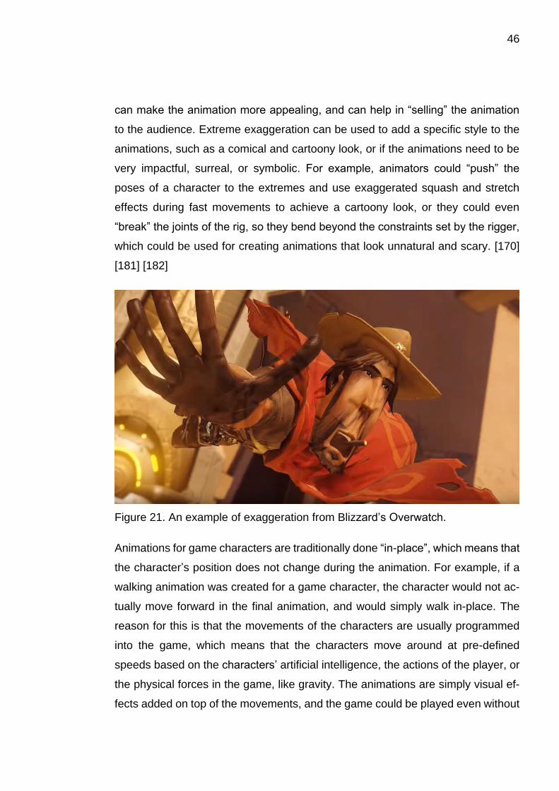
46
can make the animation more appealing, and can help in “selling” the animation
to the audience. Extreme exaggeration can be used to add a specific style to the
animations, such as a comical and cartoony look, or if the animations need to be
very impactful, surreal, or symbolic. For example, animators could “push” the
poses of a character to the extremes and use exaggerated squash and stretch
effects during fast movements to achieve a cartoony look, or they could even
“break” the joints of the rig, so they bend beyond the constraints set by the rigger,
which could be used for creating animations that look unnatural and scary. [170]
[181] [182]
Figure 21. An example of exaggeration from Blizzard’s Overwatch.
Animations for game characters are traditionally done “in-place”, which means that
the character’s position does not change during the animation. For example, if a
walking animation was created for a game character, the character would not ac-
tually move forward in the final animation, and would simply walk in-place. The
reason for this is that the movements of the characters are usually programmed
into the game, which means that the characters move around at pre-defined
speeds based on the characters’ artificial intelligence, the actions of the player, or
the physical forces in the game, like gravity. The animations are simply visual ef-
fects added on top of the movements, and the game could be played even without

47
them. However, there is an alternative option for creating game character anima-
tions, which is essentially the exact opposite of the traditional method. Root motion
is a technique which allows the animation made by the animator to drive the move-
ment of the character within the game. Root motion takes the animated motion of
the character rig’s root bone or root joint, and applies it as the movement of the
character in the game. This can be useful for complex movements, such as an
attack animation in which the character quickly lunges forward, since the move-
ment of the lunge can be difficult to replicate by programming. [183, p113] [184]
Many animations in games are different types of cycles, which are animations that
can be looped to create seamless and endless animations that repeat over and
over again. For example, a game character might have cycles for walking, running,
and idle movement, and the animations could be switched based on what the
player wanted the character to do. While the animating of a character can be a
time consuming and manual process, there are tools that can automate some of
it. For example, walk cycles and run cycles can be easily created with the 3ds Max
Character Animation Toolkit, using a tool called CATMotion. CATMotion is a pro-
cedural-motion-cycle-generation system, which allows the animator to create ani-
mation cycles by modifying different parameters, called controllers. The animator
can use these controllers to change the way different parts of the character’s body
move, and the CATMotion tool will automatically create an animation cycle based
on how the animator has set up the controllers. For example, the animator can
define the speed of the character’s movement, how the character swings their
arms, and how the toes of the character curl during walking. [179] [185] [186] [187]
[188] [189]
3.2 Methods and techniques for games on mobile and low-end devices
Since mobile and low-end devices are more limited in terms of computational
power when compared to modern computers and game consoles, there are also
more technical restrictions that need to be factored in when creating games for

48
them. In order to deal with these technical restrictions, games need to be opti-
mized, which essentially means that various features of the game are simplified
until the performance of the game is acceptable on the target devices. Most games
are optimized to some extent, but it is especially important when making games
for mobile and low-end devices. Of course, if the technical restrictions are taken
into account when initially designing and creating the features of the game, there
will be less need for optimizing them later on. Thus, while the workflow for creating
game characters remains mostly unchanged, there are numerous methods and
techniques that can be introduced to the workflow when creating game characters
for mobile games. [190]
One of the most common areas of optimization is the amount of polygons and
vertices in 3D models. While modern computers are able to display millions of
polygons and vertices in real-time, games on currently available mobile devices
should aim for less than 500,000 triangles, or less than 100,000 vertices on screen.
Additionally, the amount of vertices in an individual 3D model is limited to about
65,000 vertices. The limitations are even stricter on older mobile devices, such as
the iPhone 3GS and the original iPhone. The recommended amount of vertices
per frame is less than 40,000 for the 3GS, and less than 10,000 for the original
iPhone. Therefore, the models used in mobile games need to be relatively low
poly. [51] [191] [192] [193] [194]
When creating low poly models, a good rule of thumb is to add polygons only if
they add to the silhouette of the model, or if they are needed to ensure good de-
formations during animations. Small details which do not affect the silhouette of
the model can be depicted in the textures, instead of the model’s geometry. For
instance, a button on the shirt of a character might not affect the silhouette signif-
icantly, and therefore could be drawn into the textures of the model in order to use
less polygons. Additionally, the amount of UV seams in the model’s UV map
should be kept to a minimum, since vertices located on those UV seams will es-
sentially be duplicated when the model is processed, because they have multiple
UV coordinates. This also applies to any hard edges in the model’s shading. Hard
edges are edges in the model where the shading is split into different sections,
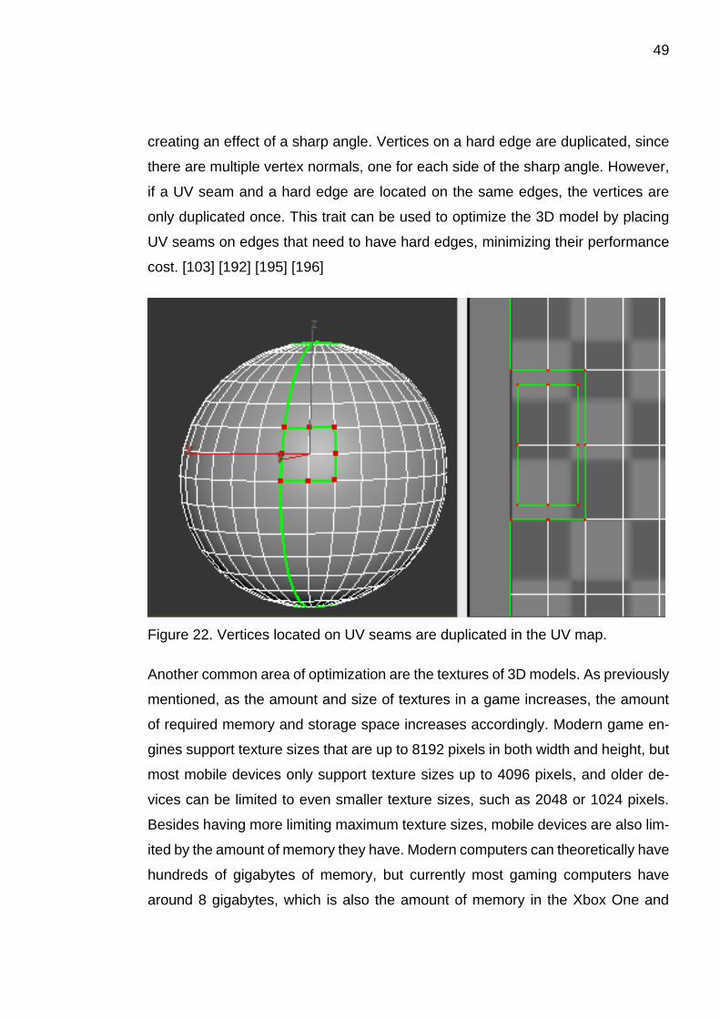
49
creating an effect of a sharp angle. Vertices on a hard edge are duplicated, since
there are multiple vertex normals, one for each side of the sharp angle. However,
if a UV seam and a hard edge are located on the same edges, the vertices are
only duplicated once. This trait can be used to optimize the 3D model by placing
UV seams on edges that need to have hard edges, minimizing their performance
cost. [103] [192] [195] [196]
Figure 22. Vertices located on UV seams are duplicated in the UV map.
Another common area of optimization are the textures of 3D models. As previously
mentioned, as the amount and size of textures in a game increases, the amount
of required memory and storage space increases accordingly. Modern game en-
gines support texture sizes that are up to 8192 pixels in both width and height, but
most mobile devices only support texture sizes up to 4096 pixels, and older de-
vices can be limited to even smaller texture sizes, such as 2048 or 1024 pixels.
Besides having more limiting maximum texture sizes, mobile devices are also lim-
ited by the amount of memory they have. Modern computers can theoretically have
hundreds of gigabytes of memory, but currently most gaming computers have
around 8 gigabytes, which is also the amount of memory in the Xbox One and

50
PlayStation 4 game consoles. In comparison, most high-end smart phones have
only 6 gigabytes of memory, while low-end smart phones might have just a few
hundred megabytes. In addition to being restricted by less memory and smaller
texture sizes, using some texture types like normal maps and transparency maps
can affect the performance of a mobile game negatively, especially on older mobile
devices such as the iPhone 4. Fortunately, there are multiple methods and tech-
niques that can be utilized to optimize the use of textures in a mobile game, which
allow for acceptable performance while still maintaining good visual quality. [117,
p58] [197] [198] [199] [200] [201] [202] [203]
One of the most common ways to optimize the amount and size of textures is to
utilize texture tiling. Tiling textures can be repeated seamlessly in one or more
directions, which means they can be used to cover large areas. Using tiling tex-
tures allows for smaller textures, since the detail of the texture can be repeated
over the surface of the model, instead of having a large texture with lots of unique
details. Tiling textures can also be reused on multiple 3D models, which means
that each individual model does not necessarily need to have a unique texture.
Therefore, using tiling textures saves memory, since the game can use less tex-
tures that are also smaller. [103] [204]
Figure 23. An example of a tiling texture.
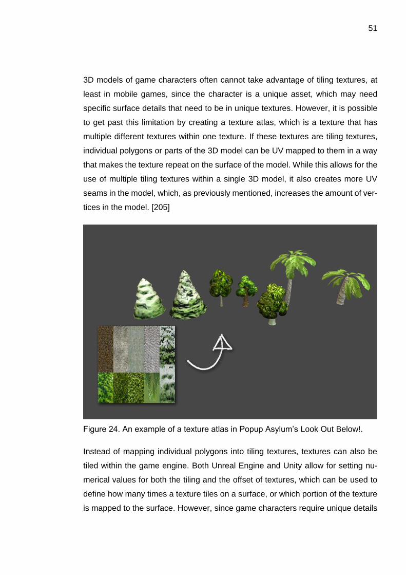
51
3D models of game characters often cannot take advantage of tiling textures, at
least in mobile games, since the character is a unique asset, which may need
specific surface details that need to be in unique textures. However, it is possible
to get past this limitation by creating a texture atlas, which is a texture that has
multiple different textures within one texture. If these textures are tiling textures,
individual polygons or parts of the 3D model can be UV mapped to them in a way
that makes the texture repeat on the surface of the model. While this allows for the
use of multiple tiling textures within a single 3D model, it also creates more UV
seams in the model, which, as previously mentioned, increases the amount of ver-
tices in the model. [205]
Figure 24. An example of a texture atlas in Popup Asylum’s Look Out Below!.
Instead of mapping individual polygons into tiling textures, textures can also be
tiled within the game engine. Both Unreal Engine and Unity allow for setting nu-
merical values for both the tiling and the offset of textures, which can be used to
define how many times a texture tiles on a surface, or which portion of the texture
is mapped to the surface. However, since game characters require unique details
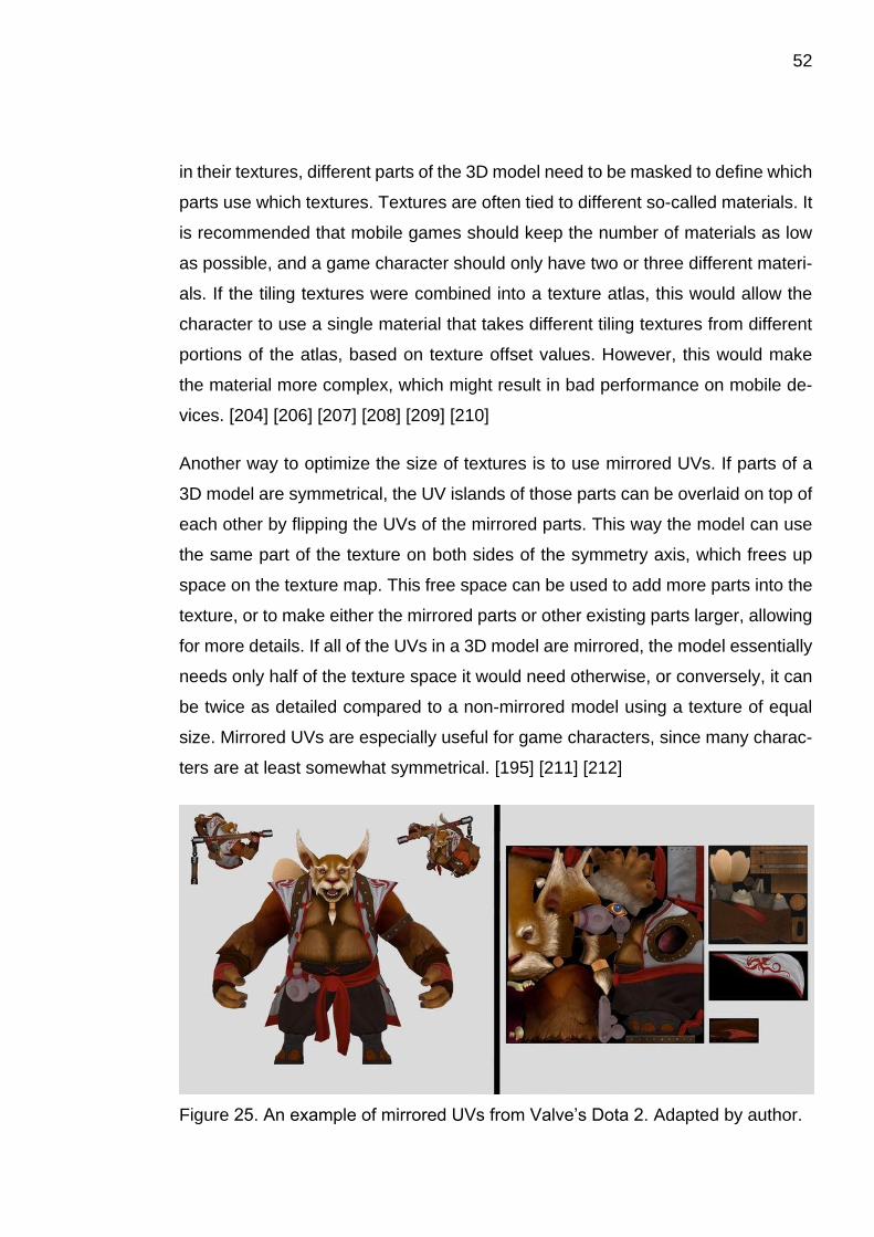
52
in their textures, different parts of the 3D model need to be masked to define which
parts use which textures. Textures are often tied to different so-called materials. It
is recommended that mobile games should keep the number of materials as low
as possible, and a game character should only have two or three different materi-
als. If the tiling textures were combined into a texture atlas, this would allow the
character to use a single material that takes different tiling textures from different
portions of the atlas, based on texture offset values. However, this would make
the material more complex, which might result in bad performance on mobile de-
vices. [204] [206] [207] [208] [209] [210]
Another way to optimize the size of textures is to use mirrored UVs. If parts of a
3D model are symmetrical, the UV islands of those parts can be overlaid on top of
each other by flipping the UVs of the mirrored parts. This way the model can use
the same part of the texture on both sides of the symmetry axis, which frees up
space on the texture map. This free space can be used to add more parts into the
texture, or to make either the mirrored parts or other existing parts larger, allowing
for more details. If all of the UVs in a 3D model are mirrored, the model essentially
needs only half of the texture space it would need otherwise, or conversely, it can
be twice as detailed compared to a non-mirrored model using a texture of equal
size. Mirrored UVs are especially useful for game characters, since many charac-
ters are at least somewhat symmetrical. [195] [211] [212]
Figure 25. An example of mirrored UVs from Valve’s Dota 2. Adapted by author.

53
To save even more memory, the amount of textures used for a 3D model can be
limited to just the color map. This will also make the material less complex, im-
proving the performance of the game. In order to still maintain good material defi-
nition in the model, the effects of the other maps need to be approximated in the
color map. For example, textures like the normal map and the ambient occlusion
map provide lighting information and shading, and to mimic their influence on the
model, the different shades of light and shadow can either be baked into the color
map from a high poly model, or they can be hand painted by the texture artist.
Similarly, the specular highlights created by the specular map and the glossiness
map can also be added into the color map. Alternatively, photographs can be used
to add material definition to the color map. [97] [107, p50-59] [107, p90-92] [107,
p123-125] [112, p28-29] [107, p273-275] [212] [213]
It is also possible to add color and details to 3D models without using any textures.
Vertex colors are color values that can be assigned to each vertex in the 3D model,
and they can be used to color the surface of the model. When a vertex color is
applied to a vertex, the color blends linearly towards the nearby vertices along the
edges of the triangles. Consequently, if two vertices next to each other have dif-
ferent colors, the colors will be blended evenly along the connecting edge. There-
fore, if areas of two different colors need to be cleanly divided without blending,
the edges between the areas need to be split, creating duplicated vertices, similar
to UV seams and hard edges. If all the vertices of a polygon have the same vertex
color, the polygon will be uniformly colored with that color. Vertex colors usually
use less memory than textures, since the color information only needs to be stored
for each vertex of the 3D model, instead of each pixel in a texture. However, since
cleanly dividing areas of different colors creates duplicated vertices, the vertex
count of the model may end up higher than if the model used textures. Also, since
the amount of detail that can be created with vertex colors depends on the polygon
density of the 3D model, it may be difficult to create intricate details, especially in
the case of low poly models. [214] [215]
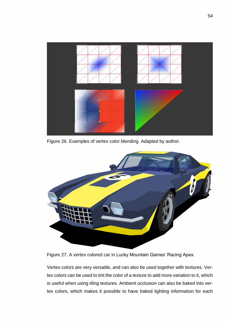
54
Figure 26. Examples of vertex color blending. Adapted by author.
Figure 27. A vertex colored car in Lucky Mountain Games’ Racing Apex.
Vertex colors are very versatile, and can also be used together with textures. Ver-
tex colors can be used to tint the color of a texture to add more variation to it, which
is useful when using tiling textures. Ambient occlusion can also be baked into ver-
tex colors, which makes it possible to have baked lighting information for each

55
unique asset, without using light maps, while still allowing for the use of reusable
tiling textures. Vertex color can also be used as the base color of a model, which
can then be complemented with overlaid textures. For example, a 3D model of a
wooden plank could be colored brown with vertex colors, and then a grayscale
pattern of wood grains could be overlaid on top of the color to add detail. As a side
note, instead of using vertex colors to directly change the colors of the 3D model,
they can also be used as masks to define which areas of a model use which tex-
tures. For example, different textures such as moss or dirt could be blended into
the 3D model of a stone wall, adding variation to the original textures. However,
for reasons listed previously, this may not be suitable for mobile games, and is
more useful for console and computer games. [215] [216] [217] [218] [219]
A similar technique to using vertex colors for coloring models, is to use a small
texture containing areas of individual colors, called a palette texture, and map the
polygons of the 3D model over these individual colors. The UVs of the model can
be overlaid on top of each other without having to worry about texture distortion or
repeating patterns, since the polygons are mapped to individual colors. Using this
technique of course limits the amount of available colors to those selected into the
palette texture. However, using a palette texture with a width and height of just 4
pixels allows for using 16 different colors, since each pixel in the texture can have
a unique color. Accordingly, larger palette textures can contain more colors, even
up to thousands or millions of colors, but using so large palette textures might be
overwhelming. Using a palette texture also makes it possible to change the color
within individual polygons, instead of just at the edges, since the polygons can be
mapped over the borders of two colored areas. Similar to using vertex colors, this
technique can increase the amount of vertices in 3D models, since each new UV
seam creates duplicate vertices. However, if the models were low poly to begin
with, this might not be a big performance issue. [221] [222]
56
3.3 Workflows for games on game consoles and computers
Games on modern game consoles and computers are less limited by the technical
restrictions of the devices than their mobile counterparts. This allows the game
artists to use more resources and utilize more advanced technologies. Addition-
ally, as technologies evolve, each new generation of game consoles allows the
game artists to take advantage of new methods and techniques, and as new and
more powerful computer components are frequently announced, both the perfor-
mance and the scope of computer games are able to increase. However, because
of these technological advances, game artists need to learn new workflows, or
incorporate new techniques into their existing workflows. Of course, new work-
flows do not always completely replace older workflows, and some new games
continue using older, or more traditional workflows. The following subchapters will
describe some of the traditional workflows that were used for creating game char-
acters during the previous console generation, as well as some of the new work-
flows that are used for making game characters for the current generation con-
soles. [223] [224]
3.3.1 Traditional workflows
Workflows similar to the following examples were widely used during the previous
generation of game consoles, or the 7th console generation, which started in 2005
when Microsoft released the Xbox 360 game console. Other 7th generation game
consoles were Sony’s PlayStation 3 and Nintendo’s Wii, both released in 2006.
These workflows, or specific parts of them, can still be used when creating game
characters for modern games, both for consoles and for computers. [225]
When creating game characters using traditional workflows, the 3D modeling pro-
cess is often divided into multiple distinct stages, which in many cases are per-
formed in different programs, or with specific plugins. The process usually begins
with modeling a low poly base mesh, which will be used for creating the high poly
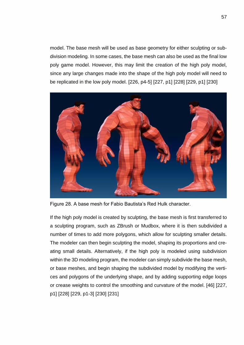
57
model. The base mesh will be used as base geometry for either sculpting or sub-
division modeling. In some cases, the base mesh can also be used as the final low
poly game model. However, this may limit the creation of the high poly model,
since any large changes made into the shape of the high poly model will need to
be replicated in the low poly model. [226, p4-5] [227, p1] [228] [229, p1] [230]
Figure 28. A base mesh for Fabio Bautista’s Red Hulk character.
If the high poly model is created by sculpting, the base mesh is first transferred to
a sculpting program, such as ZBrush or Mudbox, where it is then subdivided a
number of times to add more polygons, which allow for sculpting smaller details.
The modeler can then begin sculpting the model, shaping its proportions and cre-
ating small details. Alternatively, if the high poly is modeled using subdivision
within the 3D modeling program, the modeler can simply subdivide the base mesh,
or base meshes, and begin shaping the subdivided model by modifying the verti-
ces and polygons of the underlying shape, and by adding supporting edge loops
or crease weights to control the smoothing and curvature of the model. [46] [227,
p1] [228] [229, p1-3] [230] [231]

58
Figure 29. An example of using supporting edge loops in subdivision modeling.
Once the high poly model is finished, the next step is to create the low poly model
that will be used in the game. If the original base mesh was planned to be used as
the final game model, all that is needed is to modify the base mesh so that it fits
the shape of the high poly model. Otherwise, a new low poly model needs to be
created. This can either be done by manually modeling a low poly mesh that
matches the shape of the high poly mesh, or by retopologizing the model using
tools or plugins within the 3D program, or using a specific retopology program,
such as TopoGun. Traditionally, retopology tools are used to manually “draw” low
poly geometry on top of the existing high poly model, which allows for a lot of
control over the topology, but can also be very tedious. [226, p6-7] [227, p3] [228]
[229, p3] [230] [231] [232, p1-3] [233]
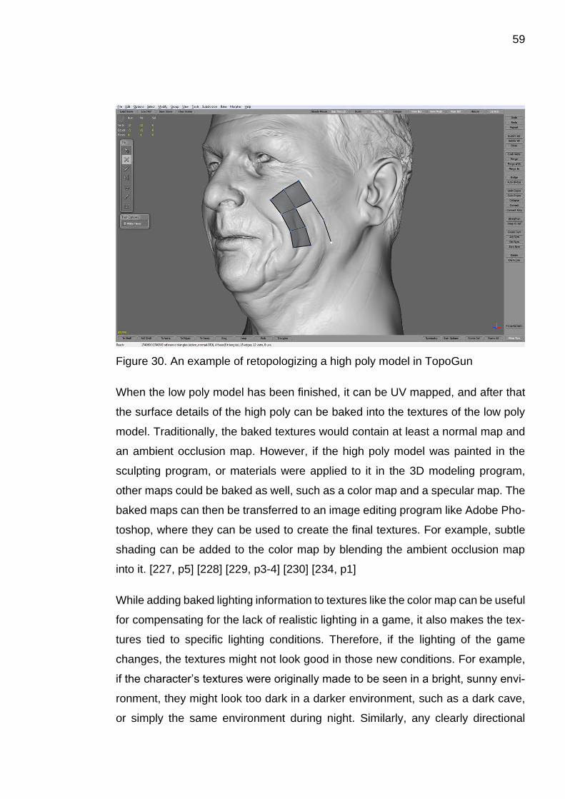
59
Figure 30. An example of retopologizing a high poly model in TopoGun
When the low poly model has been finished, it can be UV mapped, and after that
the surface details of the high poly can be baked into the textures of the low poly
model. Traditionally, the baked textures would contain at least a normal map and
an ambient occlusion map. However, if the high poly model was painted in the
sculpting program, or materials were applied to it in the 3D modeling program,
other maps could be baked as well, such as a color map and a specular map. The
baked maps can then be transferred to an image editing program like Adobe Pho-
toshop, where they can be used to create the final textures. For example, subtle
shading can be added to the color map by blending the ambient occlusion map
into it. [227, p5] [228] [229, p3-4] [230] [234, p1]
While adding baked lighting information to textures like the color map can be useful
for compensating for the lack of realistic lighting in a game, it also makes the tex-
tures tied to specific lighting conditions. Therefore, if the lighting of the game
changes, the textures might not look good in those new conditions. For example,
if the character’s textures were originally made to be seen in a bright, sunny envi-
ronment, they might look too dark in a darker environment, such as a dark cave,
or simply the same environment during night. Similarly, any clearly directional

60
shading in the color texture might look unnatural in an environment which does not
have a light source in that direction. Additionally, when creating textures using tra-
ditional workflows, texture artists often have to use a lot of trickery to compensate
for the inaccuracies of the game’s lighting, and they have to do a lot of guesswork
and trial-and-error to achieve a plausible appearance. For example, when creating
specular maps for non-metallic surfaces, the textures often need to be tinted with
a color that is the opposite of the color in the color map, to create a neutral white
specular reflection. The brightness values of the specular map and the color map
often also need to be approximated by eye, since the values are not based on any
real-world data. [81] [234, p3] [235] [236] [237] [238]
Figure 31. An example of adding blue color to the specular map of a non-metallic
(dielectric) material, to create a neutral white highlight.
Another problem with using traditional workflows is the large amount of manual
work, which can take a lot of time, and can be very tedious. For example, during
61
the 3D modeling process, the modeler essentially has to create the 3D model mul-
tiple times, since they first have to create the base mesh, then the high poly model,
and finally the low poly game model.
3.3.2 Current generation workflows
The current, or the 8th generation of consoles, started in 2012 when Nintendo re-
leased the Wii U, followed by Microsoft’s Xbox One and Sony’s PlayStation 4 in
2013. The new consoles are significantly more powerful than their predecessors,
which means that games can utilize more advanced technologies that are more
demanding in terms of computational power. This of course also applies to modern
computers, in comparison to older hardware. The tools and techniques used for
creating game art have also evolved and improved, making the process of creating
game art easier and faster. The following examples of workflows are similar to
those currently being used for creating game characters for modern console and
computer games. The specific tools and techniques will be described in more de-
tail in the next chapter. [224] [225] [239]
While traditional workflows are still usable when creating game characters for
modern games, new tools and techniques offer some significant advantages, es-
pecially in terms of artistic freedom, ease of use, and increased working speed.
For example, while traditional workflows often require the 3D modeler to first model
a low poly base mesh before they can start creating the high poly model, new
features and tools in programs such as ZBrush allow the modeler to start creating
the high poly model directly. Tools like ZSpheres and DynaMesh, and techniques
like ZSketching can be used to quickly block out the shape of a model, which can
then be transformed into a model that is ready for sculpting. Features like these
also allow the modeler to focus on creating the shape and the details of the model,
without having to worry about things like topology and poly count in the early
stages of creation. [240] [241] [242] [243, p4-5] [244, p152-173]
62
Similar to the traditional workflows, once the high poly model is finished, the low
poly game model needs to be created. While using traditional tools like TopoGun
is still an option, many programs now offer advanced retopology tools that can
either completely or partially automate the retopology process, as well as manual
retopology tools for more precise control. Depending on the model, these tools
can make the retopology process faster and less tedious. Some programs that
include tools like these are ZBrush, Mudbox, and 3D-Coat. Therefore, if the high
poly model was created in one of these programs, the modeler does not neces-
sarily need to change programs between different stages of the modeling process,
which makes the workflow more straightforward. ZBrush and 3D-Coat also offer
decent UV mapping features, although, if the UV map needs to have specific prop-
erties, UV mapping tools in other 3D programs might be more suitable for certain
tasks. [243, p4-5] [244, p229-245] [245] [246] [247] [248] [249] [250] [251]
Perhaps the biggest difference between the traditional workflows and the new
workflows is the introduction of PBR, or physically based rendering techniques,
and the new methods and tools used to create PBR textures. Physically based
rendering will be described in more detail in the next chapter, but the term essen-
tially refers to the concept of approximating realistic lighting and material proper-
ties using surface values measured from real-world materials. Using PBR materi-
als in 3D models ensures that they look believable in all lighting conditions,
whereas 3D models that are textured using the traditional workflows often look
good only in specific situations. The workflows for creating PBR textures differ sig-
nificantly from the traditional workflows. For example, the color values in PBR tex-
tures are based on values measured from real-world materials, which grounds the
textures in reality. In comparison, color values in traditional textures are often
simply approximated by eye, which leaves a lot of room for error. Additionally,
traditional workflows often rely on adding lighting information such as baked am-
bient occlusion and drawn highlights into the color map, to compensate for the lack
of realistic lighting in the game. In PBR workflows, the color map should only con-
tain the base color of the material without any lighting information, and the ambient
occlusion map should be kept as a separate texture, so the lighting system of the
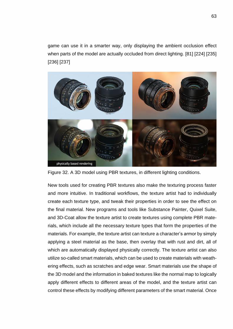
63
game can use it in a smarter way, only displaying the ambient occlusion effect
when parts of the model are actually occluded from direct lighting. [81] [224] [235]
[236] [237]
Figure 32. A 3D model using PBR textures, in different lighting conditions.
New tools used for creating PBR textures also make the texturing process faster
and more intuitive. In traditional workflows, the texture artist had to individually
create each texture type, and tweak their properties in order to see the effect on
the final material. New programs and tools like Substance Painter, Quixel Suite,
and 3D-Coat allow the texture artist to create textures using complete PBR mate-
rials, which include all the necessary texture types that form the properties of the
materials. For example, the texture artist can texture a character’s armor by simply
applying a steel material as the base, then overlay that with rust and dirt, all of
which are automatically displayed physically correctly. The texture artist can also
utilize so-called smart materials, which can be used to create materials with weath-
ering effects, such as scratches and edge wear. Smart materials use the shape of
the 3D model and the information in baked textures like the normal map to logically
apply different effects to different areas of the model, and the texture artist can
control these effects by modifying different parameters of the smart material. Once
64
the textures are finished, the individual texture types can be created automatically,
after which they can be applied to the character within the game. The texture artist
can also create their own PBR materials using tools like Substance Designer and
Bitmap2Material. [111] [252] [253] [254] [255] [256]
3.3.3 Other workflows
In addition to the previously described workflows, there are a couple of other no-
table workflows that are worth mentioning. However, these workflows will not be
covered in detail, since they are very broad subjects by themselves, and therefore
will only be briefly explained.
3D scanning is the process of capturing the shape of a physical object in the real
world, and recreating it digitally. Objects can be 3D scanned using specialized 3D
scanning devices, which can use lasers, projectors, or multiple cameras to capture
the shape of the objects. Photogrammetry is an alternative method of 3D scanning,
which uses a regular digital camera to take pictures of objects from different an-
gles, that can then be processed into a 3D model using programs like Agisoft Pho-
toScan, RealityCapture, or Autodesk ReMake. Since photogrammetry is based on
taking pictures of the objects, it can also be used to create textures for the scanned
3D model. However, this also means that the textures will contain lighting infor-
mation like shadows and highlights, which need to be removed from the textures
if they are going to be used with PBR materials. Alternatively, the object can be
brought to a studio environment, where the lighting conditions can be controlled,
and any unwanted shadows can be avoided. This of course only applies to objects
that can be moved from their original location. [257] [258] [259] [260] [261] [262]
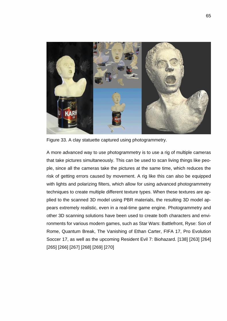
65
Figure 33. A clay statuette captured using photogrammetry.
A more advanced way to use photogrammetry is to use a rig of multiple cameras
that take pictures simultaneously. This can be used to scan living things like peo-
ple, since all the cameras take the pictures at the same time, which reduces the
risk of getting errors caused by movement. A rig like this can also be equipped
with lights and polarizing filters, which allow for using advanced photogrammetry
techniques to create multiple different texture types. When these textures are ap-
plied to the scanned 3D model using PBR materials, the resulting 3D model ap-
pears extremely realistic, even in a real-time game engine. Photogrammetry and
other 3D scanning solutions have been used to create both characters and envi-
ronments for various modern games, such as Star Wars: Battlefront, Ryse: Son of
Rome, Quantum Break, The Vanishing of Ethan Carter, FIFA 17, Pro Evolution
Soccer 17, as well as the upcoming Resident Evil 7: Biohazard. [138] [263] [264]
[265] [266] [267] [268] [269] [270]
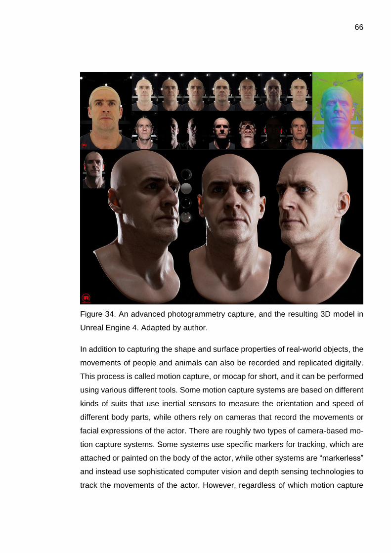
66
Figure 34. An advanced photogrammetry capture, and the resulting 3D model in
Unreal Engine 4. Adapted by author.
In addition to capturing the shape and surface properties of real-world objects, the
movements of people and animals can also be recorded and replicated digitally.
This process is called motion capture, or mocap for short, and it can be performed
using various different tools. Some motion capture systems are based on different
kinds of suits that use inertial sensors to measure the orientation and speed of
different body parts, while others rely on cameras that record the movements or
facial expressions of the actor. There are roughly two types of camera-based mo-
tion capture systems. Some systems use specific markers for tracking, which are
attached or painted on the body of the actor, while other systems are “markerless”
and instead use sophisticated computer vision and depth sensing technologies to
track the movements of the actor. However, regardless of which motion capture

67
system is used, the raw capture data often needs to be adjusted manually by ani-
mators to remove capture errors and to make it look better in the game, since, as
previously mentioned, accurately replicating the motions seen in nature may not
look as pleasing in animations as they appear in the real world. All of these sys-
tems have been used to create character animations for video games. For exam-
ple, games such as Borderlands, Killzone 2, and Resistance 3 used inertial motion
capture technologies developed by Xsens, while various camera based systems
have been used in games such as The Last of Us, Deus Ex: Mankind Divided,
Batman: Arkham Knight, Far Cry 3, The Order: 1886, Call of Duty: Ghosts, Call of
Duty: Black Ops 2, as well as the upcoming Hellblade: Senua’s Sacrifice. [125,
p335-338, 371-376] [271] [272] [273] [274] [275] [276] [277] [278] [279] [280] [281]
[282] [283] [284]
Figure 35. An example of recording motion capture for Treyarch’s Call of Duty:
Black Ops 2.
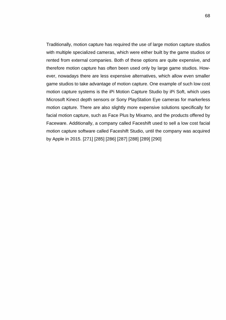
68
Traditionally, motion capture has required the use of large motion capture studios
with multiple specialized cameras, which were either built by the game studios or
rented from external companies. Both of these options are quite expensive, and
therefore motion capture has often been used only by large game studios. How-
ever, nowadays there are less expensive alternatives, which allow even smaller
game studios to take advantage of motion capture. One example of such low cost
motion capture systems is the iPi Motion Capture Studio by iPi Soft, which uses
Microsoft Kinect depth sensors or Sony PlayStation Eye cameras for markerless
motion capture. There are also slightly more expensive solutions specifically for
facial motion capture, such as Face Plus by Mixamo, and the products offered by
Faceware. Additionally, a company called Faceshift used to sell a low cost facial
motion capture software called Faceshift Studio, until the company was acquired
by Apple in 2015. [271] [285] [286] [287] [288] [289] [290]

69
4 CURRENT GENERATION TOOLS AND TECHNIQUES
The previous chapter introduced some of the workflows used for creating game
characters for the current generation of console and computer games. In this chap-
ter the tools and techniques used in those workflows will be further discussed in
more detail.
4.1 Digital sculpting
Digital sculpting is an alternative method of 3D modeling, which allows the 3D
modeler to edit the surface of the 3D model almost as if the modeler was sculpting
actual clay. The sculpting tools usually consist of different kinds of “brushes” which
the modeler can use to shape the surface of the model, instead of editing individual
polygons, edges, and vertices, like they would in a traditional polygonal modeling
program. There are several different digital sculpting programs available, and
some traditional 3D programs also include their own sculpting tools. Examples of
programs specifically designed for digital sculpting are ZBrush, Mudbox, 3D-Coat,
and Sculptris. Traditional 3D programs that have their own tools for digital sculpt-
ing include Cinema 4D, Modo, and Blender. Digital sculpting can also be per-
formed within a web browser by using a web app called Sculptfab, which is based
on the SculptGL web app by Stéphane Ginier. [26] [291] [292] [293]
There are slight differences between the sculpting features of different sculpting
programs. Programs like Sculptris, 3D-Coat, and Blender can use dynamic tessel-
lation to automatically create new geometry on the surface of the 3D model as the
modeler sculpts new shapes into it. For example, if the modeler pulls a shape out
of a character’s head to give the character a horn, the programs will automatically
create new evenly distributed polygons to construct the shape. However, the gen-
erated geometry will consist of triangles instead of quads, which means the sur-
face of the model often needs to be converted into quad-based geometry at some
70
point. Most other sculpting programs rely mostly on quad-based subdivision to add
more polygons to the shape. If more geometry is needed in specific areas of the
model, or if the polygon density of the model needs to be made more uniform, the
model can be automatically retopologized. [241] [291]
Figure 36. An example of using a brush that supports dynamic topology (tessella-
tion), compared to a brush which does not support it (left).
4.1.1 General digital sculpting workflow
As outlined in the previous chapter, the current generation workflows for creating
game characters often start with creating the high poly model in a digital sculpting
program like ZBrush. The first step in creating the high poly model is to construct
the basic shape of the model. This can be done by using a base mesh that was
previously modeled in another 3D program, or by selecting one of the pre-made
base meshes from the options provided by the sculpting program. Alternatively,
the base mesh can be created manually by using mesh generation tools within the
sculpting program. ZBrush offers multiple tools that are suitable for this purpose,
such as ZSpheres, ZSketch, Dynamesh, Shadowbox, and the program’s various
parametric primitive shape generators, like Sphere3D, Cube3D, and Cylinder3D.
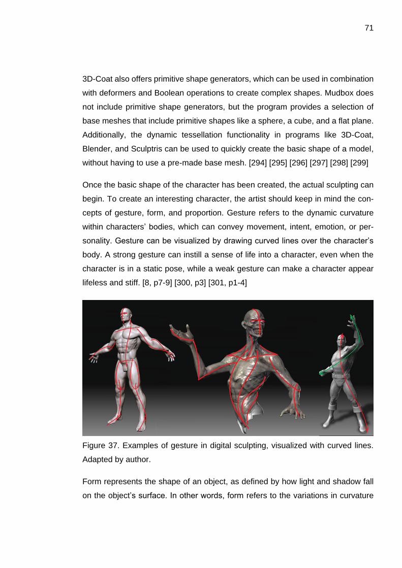
71
3D-Coat also offers primitive shape generators, which can be used in combination
with deformers and Boolean operations to create complex shapes. Mudbox does
not include primitive shape generators, but the program provides a selection of
base meshes that include primitive shapes like a sphere, a cube, and a flat plane.
Additionally, the dynamic tessellation functionality in programs like 3D-Coat,
Blender, and Sculptris can be used to quickly create the basic shape of a model,
without having to use a pre-made base mesh. [294] [295] [296] [297] [298] [299]
Once the basic shape of the character has been created, the actual sculpting can
begin. To create an interesting character, the artist should keep in mind the con-
cepts of gesture, form, and proportion. Gesture refers to the dynamic curvature
within characters’ bodies, which can convey movement, intent, emotion, or per-
sonality. Gesture can be visualized by drawing curved lines over the character’s
body. A strong gesture can instill a sense of life into a character, even when the
character is in a static pose, while a weak gesture can make a character appear
lifeless and stiff. [8, p7-9] [300, p3] [301, p1-4]
Figure 37. Examples of gesture in digital sculpting, visualized with curved lines.
Adapted by author.
Form represents the shape of an object, as defined by how light and shadow fall
on the object’s surface. In other words, form refers to the variations in curvature
72
on the object’s surface, and the variations in volume within the object. Form cre-
ates structure into the character, distinguishing different parts of the character,
such as different muscles and bones. It can also be used to define how soft or
hard a certain portion of the surface appears. For example, muscles and fat have
more subtle forms with smooth curves, while bones have more pronounced forms
with hard angles. Form can be divided into three classes: primary, secondary, and
tertiary forms. Primary forms are the biggest and most basic shapes that form the
character, like the head and its features like ears and nose. Smaller details, such
as folds of flesh and rolls of fat, are secondary forms, while tertiary forms consist
of the fine details, like the pores and wrinkles on the skin.[8, p8-9] [300, p5-7] [301,
p4-8]
Proportion is the relative size of different parts of an object, compared to each
other and the overall size of the object. When creating humanoid characters, an
artist can choose to use a so-called canon of proportions, which is a system of
rules and guidelines for creating a human character. A proportional canon gives
the artist a standard set of measurements of the relative sizes of different body
parts. There are multiple different proportional canons, many of which use the
height of the human head as the main unit of measurement. For example, the
eight-head canon measures the height of a human at eight heads tall, while other
commonly used canons measure the human height at seven and a half, or nine
heads tall. Using different canons can change the way a character is perceived. A
character using a 9-head canon can seem more heroic, while the 71⁄2-head canon
is closer to reality. Of course, none of the canons are laws that need to be obeyed,
since they are idealized systems of proportion, and there are variations in all peo-
ple. However, using canons can help the artist in creating more believable char-
acters, since their guidelines provide a good base to build upon, or a point of ref-
erence to deviate from. [8, p9] [300, p7-9] [301, p8] [302, p28]
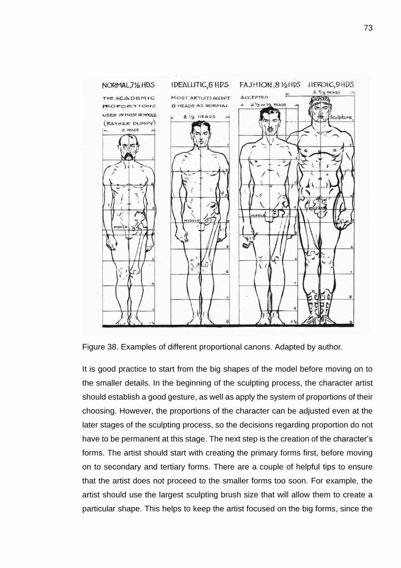
73
Figure 38. Examples of different proportional canons. Adapted by author.
It is good practice to start from the big shapes of the model before moving on to
the smaller details. In the beginning of the sculpting process, the character artist
should establish a good gesture, as well as apply the system of proportions of their
choosing. However, the proportions of the character can be adjusted even at the
later stages of the sculpting process, so the decisions regarding proportion do not
have to be permanent at this stage. The next step is the creation of the character’s
forms. The artist should start with creating the primary forms first, before moving
on to secondary and tertiary forms. There are a couple of helpful tips to ensure
that the artist does not proceed to the smaller forms too soon. For example, the
artist should use the largest sculpting brush size that will allow them to create a
particular shape. This helps to keep the artist focused on the big forms, since the
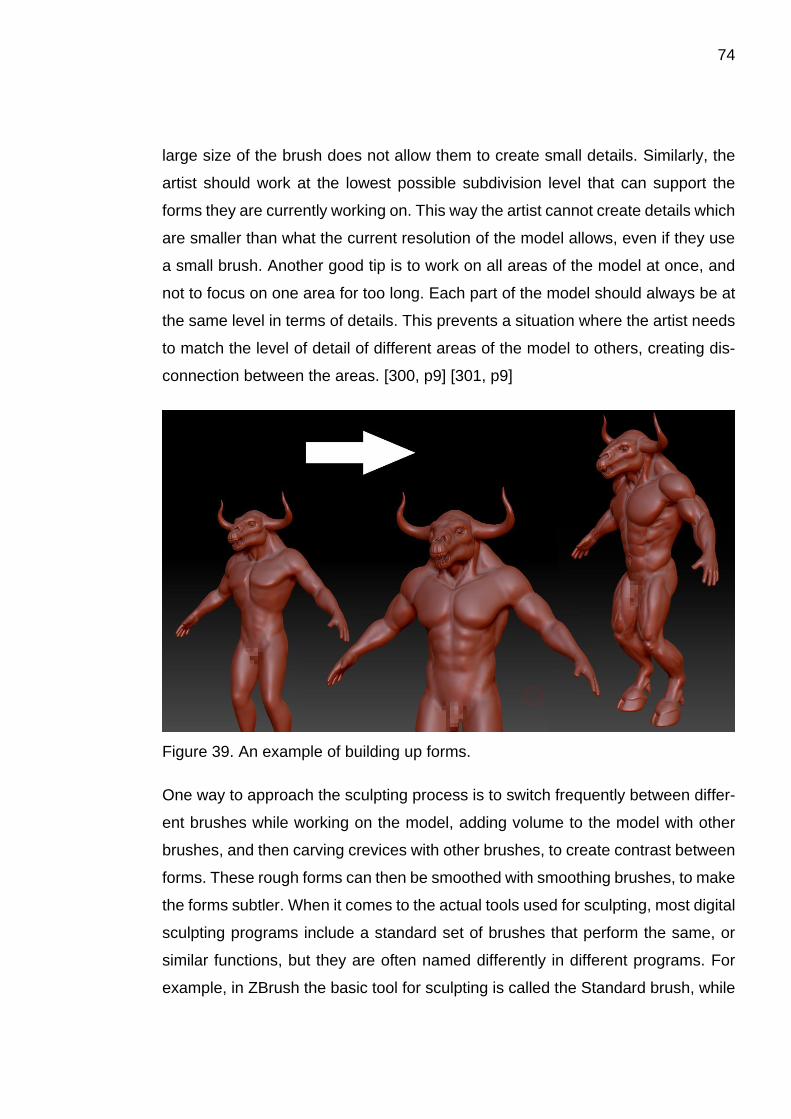
74
large size of the brush does not allow them to create small details. Similarly, the
artist should work at the lowest possible subdivision level that can support the
forms they are currently working on. This way the artist cannot create details which
are smaller than what the current resolution of the model allows, even if they use
a small brush. Another good tip is to work on all areas of the model at once, and
not to focus on one area for too long. Each part of the model should always be at
the same level in terms of details. This prevents a situation where the artist needs
to match the level of detail of different areas of the model to others, creating dis-
connection between the areas. [300, p9] [301, p9]
Figure 39. An example of building up forms.
One way to approach the sculpting process is to switch frequently between differ-
ent brushes while working on the model, adding volume to the model with other
brushes, and then carving crevices with other brushes, to create contrast between
forms. These rough forms can then be smoothed with smoothing brushes, to make
the forms subtler. When it comes to the actual tools used for sculpting, most digital
sculpting programs include a standard set of brushes that perform the same, or
similar functions, but they are often named differently in different programs. For
example, in ZBrush the basic tool for sculpting is called the Standard brush, while
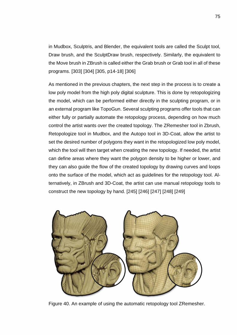
75
in Mudbox, Sculptris, and Blender, the equivalent tools are called the Sculpt tool,
Draw brush, and the SculptDraw brush, respectively. Similarly, the equivalent to
the Move brush in ZBrush is called either the Grab brush or Grab tool in all of these
programs. [303] [304] [305, p14-18] [306]
As mentioned in the previous chapters, the next step in the process is to create a
low poly model from the high poly digital sculpture. This is done by retopologizing
the model, which can be performed either directly in the sculpting program, or in
an external program like TopoGun. Several sculpting programs offer tools that can
either fully or partially automate the retopology process, depending on how much
control the artist wants over the created topology. The ZRemesher tool in Zbrush,
Retopologize tool in Mudbox, and the Autopo tool in 3D-Coat, allow the artist to
set the desired number of polygons they want in the retopologized low poly model,
which the tool will then target when creating the new topology. If needed, the artist
can define areas where they want the polygon density to be higher or lower, and
they can also guide the flow of the created topology by drawing curves and loops
onto the surface of the model, which act as guidelines for the retopology tool. Al-
ternatively, in ZBrush and 3D-Coat, the artist can use manual retopology tools to
construct the new topology by hand. [245] [246] [247] [248] [249]
Figure 40. An example of using the automatic retopology tool ZRemesher.

76
Once the low poly model has been created and UV mapped, the details of the high
poly model can be baked into the textures of the low poly model. As with retopol-
ogizing, this can be done either in an external program, like xNormal, or directly
within the digital sculpting program. However, the baking tools in digital sculpting
programs are often less advanced, and allow for less control over the bake than
tools in dedicated baking software, or traditional 3D modeling programs. For ex-
ample, the baking tool in Mudbox has two different baking methods, called the Ray
Casting method and the Subdivision method. The Ray Casting method creates the
baked textures by comparing the shape of the high poly model to the shape of the
low poly model within a set distance, which requires that the models are manually
aligned to be as close to each other as possible. Even if the models are properly
aligned, using the method may still result in unwanted artifacts in the baked tex-
tures. The Subdivision method compares different subdivision levels of the same
model to each other, and records the differences in positions between the corre-
sponding points on their surfaces. This method will result in fewer artifacts in the
baked textures, but it can only be used when the low and high poly models are
different subdivision levels of the same model. The Subdivision method is also not
as accurate in capturing the differences in surface height between the subdivision
levels, compared to the Ray Casting method. In comparison to Mudbox, the baking
tools in many traditional 3D modeling programs allow for far more control over the
baking process. For example, in 3ds Max it is possible to use a secondary model,
a so-called cage, to guide the baking process. This cage is created by applying a
Projection Modifier to the low poly model, which creates a copy of the model’s
geometry, which is used as the cage. The surface of the cage can then be pushed
outwards from the original low poly model, so that the cage completely covers both
the low poly model, and the high poly model that has been aligned with the low
poly model in preparation for the baking process. The cage can also be manually
edited in order to match the shape of the high poly model as closely as possible,
so that all of its details can be baked properly without any unwanted distortions or
artifacts. [307] [308] [309]
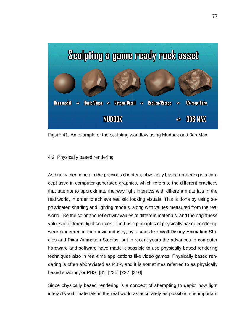
77
Figure 41. An example of the sculpting workflow using Mudbox and 3ds Max.
4.2 Physically based rendering
As briefly mentioned in the previous chapters, physically based rendering is a con-
cept used in computer generated graphics, which refers to the different practices
that attempt to approximate the way light interacts with different materials in the
real world, in order to achieve realistic looking visuals. This is done by using so-
phisticated shading and lighting models, along with values measured from the real
world, like the color and reflectivity values of different materials, and the brightness
values of different light sources. The basic principles of physically based rendering
were pioneered in the movie industry, by studios like Walt Disney Animation Stu-
dios and Pixar Animation Studios, but in recent years the advances in computer
hardware and software have made it possible to use physically based rendering
techniques also in real-time applications like video games. Physically based ren-
dering is often abbreviated as PBR, and it is sometimes referred to as physically
based shading, or PBS. [81] [235] [237] [310]
Since physically based rendering is a concept of attempting to depict how light
interacts with materials in the real world as accurately as possible, it is important
78
to understand how light actually behaves in the real world. When a ray of light hits
the surface of an object in the real world, with most common materials there are
generally four things that can happen. Firstly, the light can be reflected directly
from the surface of the object, causing a specular reflection. This is what allows
mirrors to reflect their surroundings, and what causes bright highlights on glossy
objects. Secondly, the light can enter the surface of the object and transmit directly
through it, making it appear transparent. This is called refraction, and a typical
characteristic of refraction is that the ray of light often slightly changes direction,
or bends, when it travels from one material to another. This phenomenon can be
witnessed when viewing through a glass lens, or into a bowl of water. Thirdly, the
light can enter the surface of the object, but instead of directly passing through it,
the light may scatter within the material of the object, eventually exiting the object
from a seemingly random point, and at a seemingly random angle. If the light exits
the object from the side opposite to where it entered, the material will appear trans-
lucent, like thin paper or tree leaves. If the light exits the object on the same side
from which it entered, the material will appear opaque, like rock, wood, or rubber.
Depending on how far the light scatters before exiting the object, this effect can be
referred to with different terms, such as diffuse reflection, sub-surface scattering,
or translucency. Finally, the light may end up being absorbed into the material,
usually converting into infrared radiation, commonly known as heat, which is invis-
ible to human eyes. Consequently, this is the reason why humans perceive color
in objects, since different materials absorb varying amounts of different wave-
lengths of light. A white material scatters and absorbs all wavelengths of light
nearly equally, while a blue material scatters primarily blue wavelengths of light,
as the other wavelengths are mostly absorbed into the material. These examples
are of course only the most basic interactions which light has with the most com-
mon material types, and there are many other phenomena that light can cause
when interacting with certain, more unique materials. [311] [312] [313, p2-6] [314]

79
Figure 42. An example of how light can interact with materials. Adapted by author.
An important principle of physically based rendering is the concept of energy con-
servation. Energy conservation essentially means that the amount of light leaving
the surface of the material can never be greater than the amount of light that was
originally received by the surface, unless the material emits light itself. Because of
this, reflection and scattering of light are mutually exclusive. Therefore, a material
with a high specular reflectivity will have a low diffuse reflectivity, and a material
with a high diffuse reflectivity will have a low specular reflectivity. This also applies
to the transmission of light, which means that translucent and transparent materi-
als will reflect less of the received light, since part of it passes through the material.
Energy conservation is usually enforced by the application, which means that the
principle applies even if a physically incorrect material is created by an artist. [311]
[313, p7]
Because PBR systems only attempt to approximate the behavior of light in the real
world, instead of completely simulating it, it is common to heavily simplify the com-
plexity of the behavior. For example, while there are countless different types of
materials in the real world, most of them can be classified into three main groups:
insulators, semiconductors, and conductors. In many cases, only two of these
80
need to be taken into account: insulators, which are often called dielectrics, and
conductors. Dielectrics are the most common materials, which include materials
like stone, plastic, wood, water, and glass. Conductors on the other hand are
mostly different types of metals, like iron, aluminum, copper, silver, and gold. It is
important to be able to identify which group a material belongs to, since light inter-
acts very differently with materials from each group. For example, a material that
is pure metal does not have any diffuse reflection, but instead all of the light that
is not absorbed by the material is reflected as a specular reflection. Therefore,
pure metals often have high values of specular reflectivity, with some metals ap-
proaching 100% specular reflectivity, which means that almost all of the light that
hits the material is reflected from it. In comparison, the specular reflectivity of most
dielectrics is usually less than 4%, with the exception of some common gem-
stones, which still reflect only 5 to 17 percent of the received light as a specular
reflection. [311] [313, p9-10] [315]
In PBR systems, the diffuse reflection of a material is defined by a property called
the albedo, but depending on what program is used, it may also be referred to as
diffuse or base color. The albedo can be controlled either with a constant value, or
with a texture called an albedo map, which is similar to the diffuse map used in the
traditional texturing workflows. However, unlike the diffuse map, an albedo map
should not contain any lighting information, like shadows or highlights. In a PBR
system the highlights are caused by the specular reflection, and the shadows are
controlled by the application based on the lighting, sometimes with the help of a
separate ambient occlusion texture. Any additional lighting information in the al-
bedo map would contradict the lighting in the application, and would be physically
incorrect. The color values of the albedo map should also correspond to the diffuse
reflectivity of the real-world material that the PBR material is attempting to imitate.
[81] [311] [316, p5-6]
The properties used to define the specular reflectivity of a material vary between
different implementations of PBR. One common implementation is to use a prop-
erty called reflectivity, which can also be referred to as specularity, specular level,
or simply specular, depending on the software. Similar to the albedo, specularity
81
can be controlled either with a constant value, or with a texture called a specular
map. The color values of the specular map should be derived from real-world
measured values, which means that dielectrics and conductors tend to appear
very differently on the map. Since the specular reflectivity of dielectrics is so low
compared to conductors, they appear mostly as different shades of dark gray. In
comparison, the values for conductors are usually much brighter, and may also be
colored, since certain conductors absorb some wavelengths of light more than
others, causing their specular reflections to be colored. This effect can be seen in
metals like gold and copper. [311] [316, p5, 14-15]
Another property that greatly influences the appearance of a material is the rough-
ness or glossiness of the material’s surface. This property can be referred to as
glossiness, roughness, smoothness, or microsurface, and it approximates the way
light interacts with microscopic irregularities in the surface of the material. Since
these irregularities are microscopic, they are too small to be represented in the
geometry of an object, or a normal map. Instead, they are represented either as
constant values, or as different grayscale values in a specific texture, which is
referred to with different names depending on the software. In the real world, these
microscopic irregularities in the surface of the material affect the direction in which
the light is reflected from the surface. The more irregularities there are, the more
the reflected rays of light spread in different directions, making the specular reflec-
tion appear dimmer and blurrier, which makes the surface of the material appear
more rough. Conversely, the less irregularities there are, the less the specular re-
flection is spread, making it appear brighter and clearer, which makes the material
appear glossy. However, even though the specular reflection appears dim when
the surface of the material is rough, the actual intensity of the reflection is not
affected. The amount of light that is reflected off the surface remains the same,
but the light is simply spread over a larger area. In theory, both the specular re-
flection and the diffuse reflection are affected by the microscopic irregularities in
the surface. However, since diffuse reflection is already reflected at seemingly ran-
dom angles, the effect of the irregularities is barely noticeable, and therefore it is
ignored in some implementations. [311] [313, p5] [316, p10]
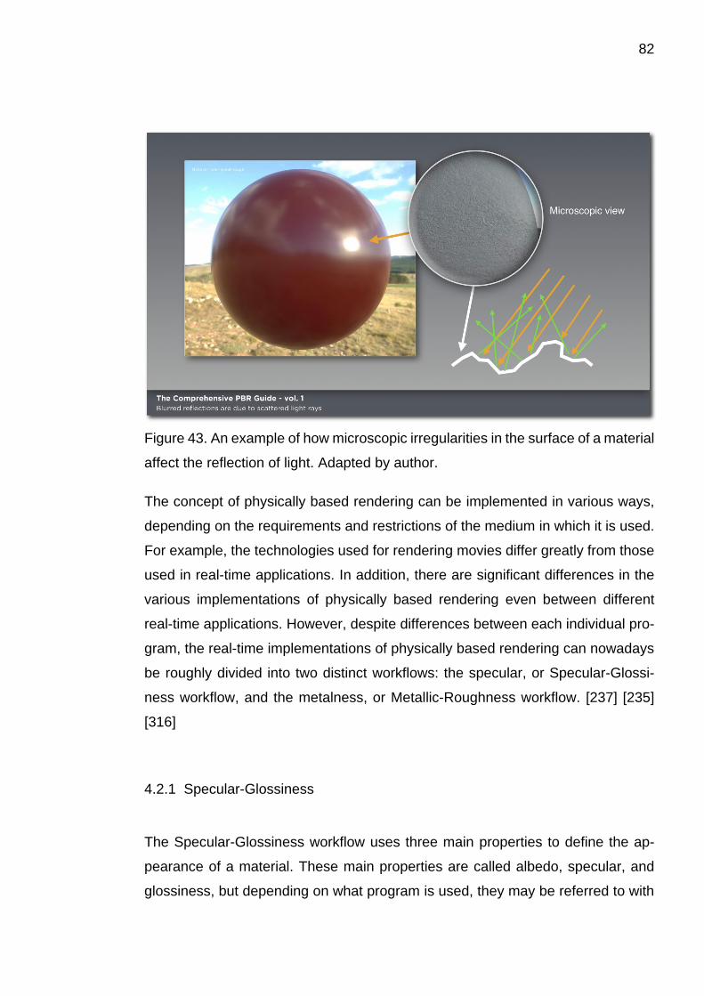
82
Figure 43. An example of how microscopic irregularities in the surface of a material
affect the reflection of light. Adapted by author.
The concept of physically based rendering can be implemented in various ways,
depending on the requirements and restrictions of the medium in which it is used.
For example, the technologies used for rendering movies differ greatly from those
used in real-time applications. In addition, there are significant differences in the
various implementations of physically based rendering even between different
real-time applications. However, despite differences between each individual pro-
gram, the real-time implementations of physically based rendering can nowadays
be roughly divided into two distinct workflows: the specular, or Specular-Glossi-
ness workflow, and the metalness, or Metallic-Roughness workflow. [237] [235]
[316]
4.2.1 Specular-Glossiness
The Specular-Glossiness workflow uses three main properties to define the ap-
pearance of a material. These main properties are called albedo, specular, and
glossiness, but depending on what program is used, they may be referred to with

83
different terms. It is also common to complement the three main properties with
additional properties like transparency or translucency, or textures like normal
maps, ambient occlusion maps, and height maps. The Specular-Glossiness work-
flow is supported by programs like the Unity game engine, Marmoset Toolbag, and
Allegorithmic’s Substance products. [81] [316, p13] [317]
The three main properties of the Specular-Glossiness workflow can be controlled
either with constant values, or with textures. The corresponding textures are com-
monly referred to as the albedo map, the specular map, and the glossiness map.
The albedo map contains the color values that represent the diffuse reflectivity of
dielectric materials. Pure metals appear black in the albedo map, since they do
not have a diffuse reflection. However, if the metal is oxidized, or is covered in dirt
or dust, those areas will appear colored in the albedo map, since they are dielectric
materials. In contrast, the specular map contains the specular reflectivity values
for both dielectrics and conductors. Most dielectrics will look very similar in the
specular map, whereas metals can have significant differences between each
other. Since some metals have colored reflections, the specular map needs to be
a color texture, instead of a grayscale texture. Finally, the glossiness map de-
scribes the amount of microscopic irregularities on the surface of the material as
grayscale values. White represents a completely glossy surface, while black rep-
resents a completely rough surface. [316, p13-16]
There are certain advantages of using the Specular-Glossiness workflow instead
of other workflows. Firstly, the Specular-Glossiness allows for a lot control over
the specular reflectivity of dielectric materials, which means that it is possible to
create more accurate representations of dielectric materials. Secondly, the Spec-
ular-Glossiness workflow creates less visible edge artifacts in transitions between
dielectrics and conductors, when compared to some other workflows. Of course,
there are also some disadvantages of using the Specular-Glossiness workflow.
Firstly, since the specular map allows for a lot of control over the dielectric materi-
als, it is also very easy to create dielectric materials that have physically incorrect
specular reflectivity values. Secondly, since the specular reflectivity values for di-
electric materials use such a narrow slice of the full range of reflectivity, textures
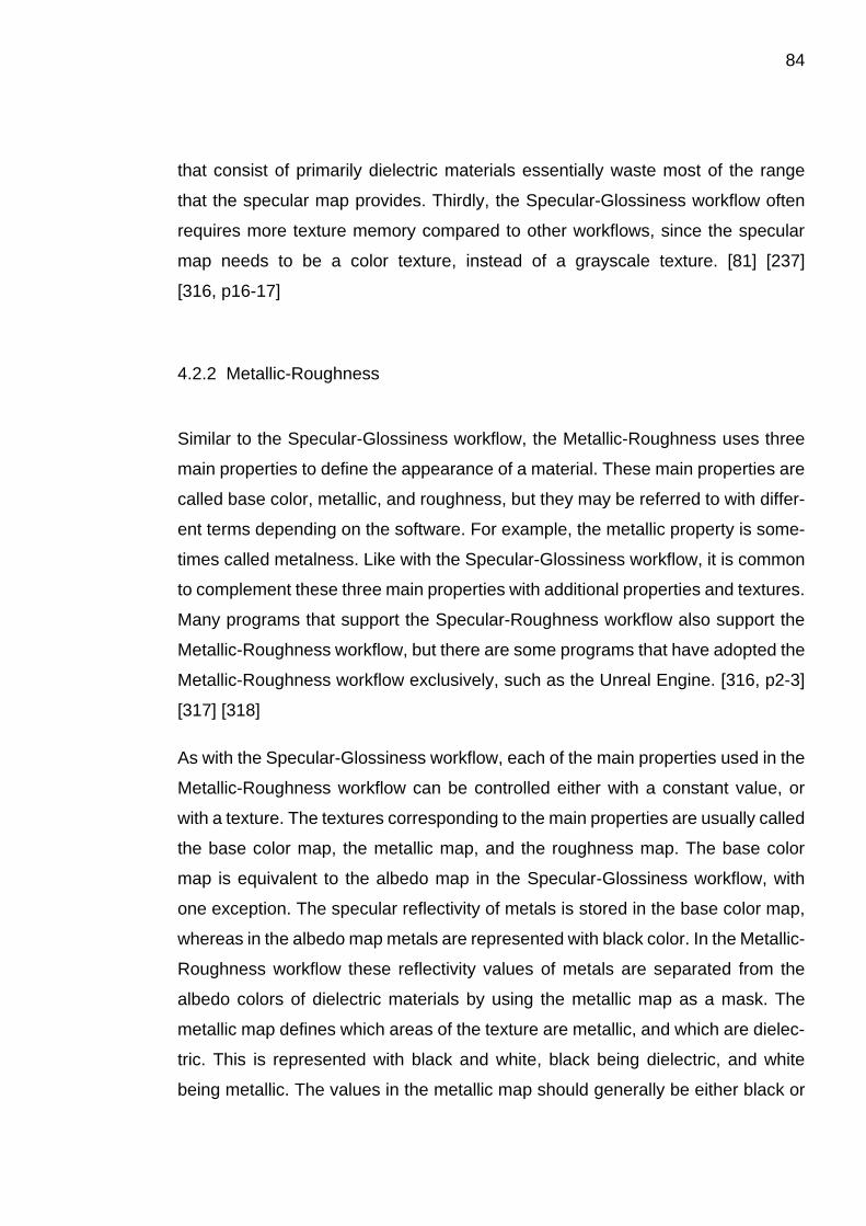
84
that consist of primarily dielectric materials essentially waste most of the range
that the specular map provides. Thirdly, the Specular-Glossiness workflow often
requires more texture memory compared to other workflows, since the specular
map needs to be a color texture, instead of a grayscale texture. [81] [237]
[316, p16-17]
4.2.2 Metallic-Roughness
Similar to the Specular-Glossiness workflow, the Metallic-Roughness uses three
main properties to define the appearance of a material. These main properties are
called base color, metallic, and roughness, but they may be referred to with differ-
ent terms depending on the software. For example, the metallic property is some-
times called metalness. Like with the Specular-Glossiness workflow, it is common
to complement these three main properties with additional properties and textures.
Many programs that support the Specular-Roughness workflow also support the
Metallic-Roughness workflow, but there are some programs that have adopted the
Metallic-Roughness workflow exclusively, such as the Unreal Engine. [316, p2-3]
[317] [318]
As with the Specular-Glossiness workflow, each of the main properties used in the
Metallic-Roughness workflow can be controlled either with a constant value, or
with a texture. The textures corresponding to the main properties are usually called
the base color map, the metallic map, and the roughness map. The base color
map is equivalent to the albedo map in the Specular-Glossiness workflow, with
one exception. The specular reflectivity of metals is stored in the base color map,
whereas in the albedo map metals are represented with black color. In the Metallic-
Roughness workflow these reflectivity values of metals are separated from the
albedo colors of dielectric materials by using the metallic map as a mask. The
metallic map defines which areas of the texture are metallic, and which are dielec-
tric. This is represented with black and white, black being dielectric, and white
being metallic. The values in the metallic map should generally be either black or
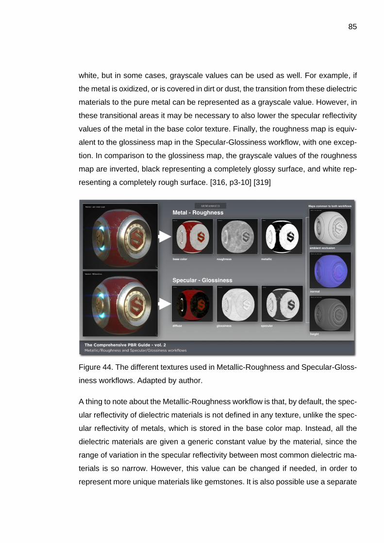
85
white, but in some cases, grayscale values can be used as well. For example, if
the metal is oxidized, or is covered in dirt or dust, the transition from these dielectric
materials to the pure metal can be represented as a grayscale value. However, in
these transitional areas it may be necessary to also lower the specular reflectivity
values of the metal in the base color texture. Finally, the roughness map is equiv-
alent to the glossiness map in the Specular-Glossiness workflow, with one excep-
tion. In comparison to the glossiness map, the grayscale values of the roughness
map are inverted, black representing a completely glossy surface, and white rep-
resenting a completely rough surface. [316, p3-10] [319]
Figure 44. The different textures used in Metallic-Roughness and Specular-Gloss-
iness workflows. Adapted by author.
A thing to note about the Metallic-Roughness workflow is that, by default, the spec-
ular reflectivity of dielectric materials is not defined in any texture, unlike the spec-
ular reflectivity of metals, which is stored in the base color map. Instead, all the
dielectric materials are given a generic constant value by the material, since the
range of variation in the specular reflectivity between most common dielectric ma-
terials is so narrow. However, this value can be changed if needed, in order to
represent more unique materials like gemstones. It is also possible use a separate
86
specular map if the textures need to represent multiple materials, or if the specular
reflections of some unique dielectrics need to be colored, for example. [81] [237]
The Metallic-Roughness workflow has certain advantages over the Specular-
Glossiness workflow. The Metallic-Roughness workflow may be easier to under-
stand conceptually, since the base color map defines the color of the material re-
gardless of whether the material is a dielectric or a conductor. The workflow also
has a clear distinction between dielectrics and conductors, since materials are de-
fined as one or the other in the metallic map. This simplifies the process of creating
materials, and may make it more difficult to create physically incorrect materials.
Finally, the Metallic-Roughness workflow tends to use less texture memory in com-
parison to the Specular-Glossiness workflow. This is a consequence of using a
constant value for the specular reflectivity of dielectric materials, and storing the
values of metals in the base color map, instead of using a separate specular map.
Therefore, even though the Metallic-Roughness workflow requires a metallic map
in place of the specular map used in the Specular-Glossiness workflow, the me-
tallic map is stored as a grayscale texture, which takes up less texture memory
than the full color specular map. Obviously, the Metallic-Roughness workflow also
has its disadvantages. One of the most apparent disadvantages are the white
edge artifacts that appear on the transitions between dielectric materials and met-
als. The Specular-Glossiness workflow also has similar edge artifacts, but they are
black instead of white, which makes them less visible in many cases. Another dis-
advantage is that, as mentioned, there is less control over the specular reflectivity
of dielectrics unless an additional specular map is added. This means that the
dielectric materials may appear less realistic when compared to dielectric materi-
als created using the Specular-Glossiness workflow. While this can be fixed with
an additional specular map, it also means that the material will use more texture
memory. [81] [237] [316, p11-12]
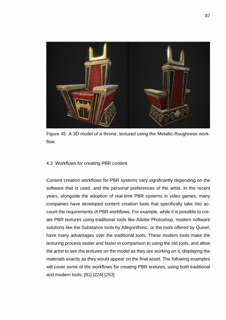
87
Figure 45. A 3D model of a throne, textured using the Metallic-Roughness work-
flow.
4.3 Workflows for creating PBR content
Content creation workflows for PBR systems vary significantly depending on the
software that is used, and the personal preferences of the artist. In the recent
years, alongside the adoption of real-time PBR systems in video games, many
companies have developed content creation tools that specifically take into ac-
count the requirements of PBR workflows. For example, while it is possible to cre-
ate PBR textures using traditional tools like Adobe Photoshop, modern software
solutions like the Substance tools by Allegorithmic, or the tools offered by Quixel,
have many advantages over the traditional tools. These modern tools make the
texturing process easier and faster in comparison to using the old tools, and allow
the artist to see the textures on the model as they are working on it, displaying the
materials exactly as they would appear on the final asset. The following examples
will cover some of the workflows for creating PBR textures, using both traditional
and modern tools. [81] [224] [253]
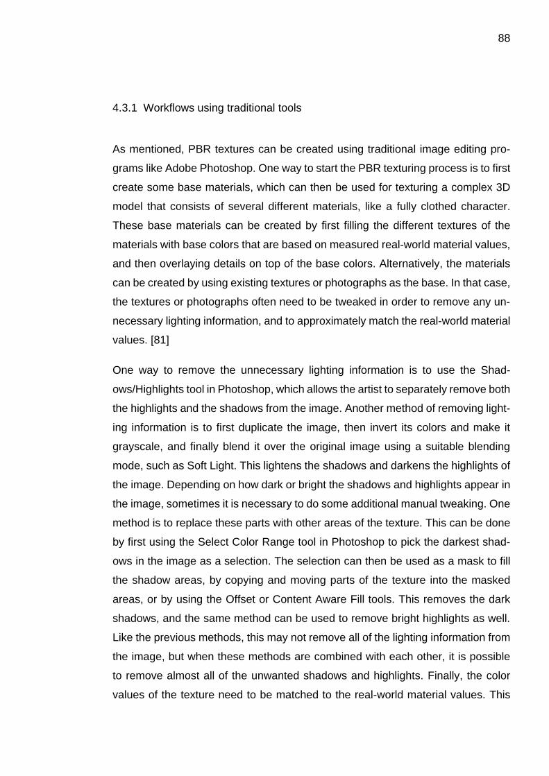
88
4.3.1 Workflows using traditional tools
As mentioned, PBR textures can be created using traditional image editing pro-
grams like Adobe Photoshop. One way to start the PBR texturing process is to first
create some base materials, which can then be used for texturing a complex 3D
model that consists of several different materials, like a fully clothed character.
These base materials can be created by first filling the different textures of the
materials with base colors that are based on measured real-world material values,
and then overlaying details on top of the base colors. Alternatively, the materials
can be created by using existing textures or photographs as the base. In that case,
the textures or photographs often need to be tweaked in order to remove any un-
necessary lighting information, and to approximately match the real-world material
values. [81]
One way to remove the unnecessary lighting information is to use the Shad-
ows/Highlights tool in Photoshop, which allows the artist to separately remove both
the highlights and the shadows from the image. Another method of removing light-
ing information is to first duplicate the image, then invert its colors and make it
grayscale, and finally blend it over the original image using a suitable blending
mode, such as Soft Light. This lightens the shadows and darkens the highlights of
the image. Depending on how dark or bright the shadows and highlights appear in
the image, sometimes it is necessary to do some additional manual tweaking. One
method is to replace these parts with other areas of the texture. This can be done
by first using the Select Color Range tool in Photoshop to pick the darkest shad-
ows in the image as a selection. The selection can then be used as a mask to fill
the shadow areas, by copying and moving parts of the texture into the masked
areas, or by using the Offset or Content Aware Fill tools. This removes the dark
shadows, and the same method can be used to remove bright highlights as well.
Like the previous methods, this may not remove all of the lighting information from
the image, but when these methods are combined with each other, it is possible
to remove almost all of the unwanted shadows and highlights. Finally, the color
values of the texture need to be matched to the real-world material values. This
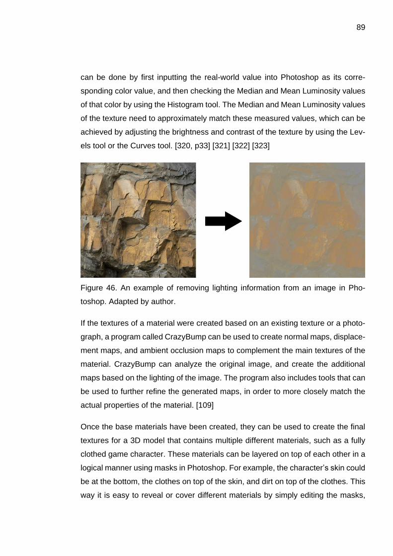
89
can be done by first inputting the real-world value into Photoshop as its corre-
sponding color value, and then checking the Median and Mean Luminosity values
of that color by using the Histogram tool. The Median and Mean Luminosity values
of the texture need to approximately match these measured values, which can be
achieved by adjusting the brightness and contrast of the texture by using the Lev-
els tool or the Curves tool. [320, p33] [321] [322] [323]
Figure 46. An example of removing lighting information from an image in Pho-
toshop. Adapted by author.
If the textures of a material were created based on an existing texture or a photo-
graph, a program called CrazyBump can be used to create normal maps, displace-
ment maps, and ambient occlusion maps to complement the main textures of the
material. CrazyBump can analyze the original image, and create the additional
maps based on the lighting of the image. The program also includes tools that can
be used to further refine the generated maps, in order to more closely match the
actual properties of the material. [109]
Once the base materials have been created, they can be used to create the final
textures for a 3D model that contains multiple different materials, such as a fully
clothed game character. These materials can be layered on top of each other in a
logical manner using masks in Photoshop. For example, the character’s skin could
be at the bottom, the clothes on top of the skin, and dirt on top of the clothes. This
way it is easy to reveal or cover different materials by simply editing the masks,
90
like adding or removing dirt from the clothes. However, this process must be rep-
licated for each of the texture maps of the materials, in order to accurately repre-
sent each material, which may end up being somewhat tedious. Additionally, while
working with different textures in Photoshop, it may be difficult to envision how the
end result will look like when the textures are applied onto the actual 3D model in
the game. [81]
4.3.2 Workflows using modern tools
Modern tools used for PBR texturing offer significant advantages over the tradi-
tional tools, making the texturing process faster, easier, and more intuitive. For
example, they allow the artist to apply complete materials onto the 3D model, with
all the required maps included in the material itself, instead of needing to edit each
texture of the material individually in Photoshop. The materials can also be layered
on top of each other by painting the materials directly on the surface of the 3D
model, instead of working with the two-dimensional textures in Photoshop. The
following examples list some of the texturing methods used with the modern PBR
texturing tools, and some of the state-of-the-art features of those tools. [253] [324]
A common way to initially apply materials to a 3D model is to use so-called Color
IDs, or Material IDs. Color IDs are essentially different uniform colors applied to
different parts of a model, which can be applied by using materials, vertex colors,
or textures. The purpose of using Color IDs is to initially define which parts of a
model use the same materials. For example, the gloves and jacket of a character
might be leather, while his sword and belt buckle might be steel, in which case the
leather parts would be assigned a different Color ID than the steel parts. The Color
IDs can be applied directly to a low poly model, and then baked to a Color ID map,
or they can be applied to a high poly model, and then baked to the Color ID map
of the low poly model, since some of the detail present in the high poly model might
not be modeled into the geometry of the low poly model. For example, gold inlays
in a sword might be embossed in the geometry of a high poly model, while they
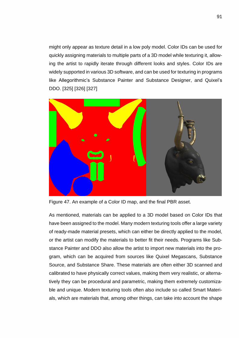
91
might only appear as texture detail in a low poly model. Color IDs can be used for
quickly assigning materials to multiple parts of a 3D model while texturing it, allow-
ing the artist to rapidly iterate through different looks and styles. Color IDs are
widely supported in various 3D software, and can be used for texturing in programs
like Allegorithmic’s Substance Painter and Substance Designer, and Quixel’s
DDO. [325] [326] [327]
Figure 47. An example of a Color ID map, and the final PBR asset.
As mentioned, materials can be applied to a 3D model based on Color IDs that
have been assigned to the model. Many modern texturing tools offer a large variety
of ready-made material presets, which can either be directly applied to the model,
or the artist can modify the materials to better fit their needs. Programs like Sub-
stance Painter and DDO also allow the artist to import new materials into the pro-
gram, which can be acquired from sources like Quixel Megascans, Substance
Source, and Substance Share. These materials are often either 3D scanned and
calibrated to have physically correct values, making them very realistic, or alterna-
tively they can be procedural and parametric, making them extremely customiza-
ble and unique. Modern texturing tools often also include so called Smart Materi-
als, which are materials that, among other things, can take into account the shape

92
of a 3D model, and baked maps such as the normal map and the ambient occlu-
sion map. Smart Materials can be used for creating weathering effects like dust
accumulating on top of the model and into its crevices, or to add scratches and
scuff marks on the protruding edges of the model to create realistic wear and tear,
for example. Using the parameters of a Smart Material, these effects can be in-
creased or decreased, as well as randomized to create different variations. This
kind of partial automation makes the texturing process significantly faster, since
the artist does not have to create these effects by hand into every edge and crevice
of the model. However, the artist still has the option to manually apply additional
unique touches to the textures, the Smart Material simply gives the artist a good
base to build upon. Smart Materials can be used in programs like Substance
Painter, Quixel DDO, and 3D-Coat. [253] [254] [328] [329] [330] [331] [332] [333]
In addition to simply applying materials to a 3D model, programs like Substance
Painter, Quixel DDO, and 3D-Coat also allow the artist to paint materials, textures,
colors, and masks directly onto the surface of the 3D model. All of these programs
include a paint brush tool, which can be used with different settings to achieve
different kinds of brushstrokes. For example, the paint brush can be equipped with
a mask shaped like a splatter stain, which can be used for applying paint splatters
onto the model. Substance Painter also includes a tool called Physical Paint, which
simulates different kinds of effects using particle physics. This can be used to cre-
ate various realistic effects, like stains caused by leaking fluids, or burn marks
caused by fire. Painting features like these give the artist a lot of creative freedom
over the texture creation, instead of only relying on base materials and Smart Ma-
terials. [252] [253] [334] [335]
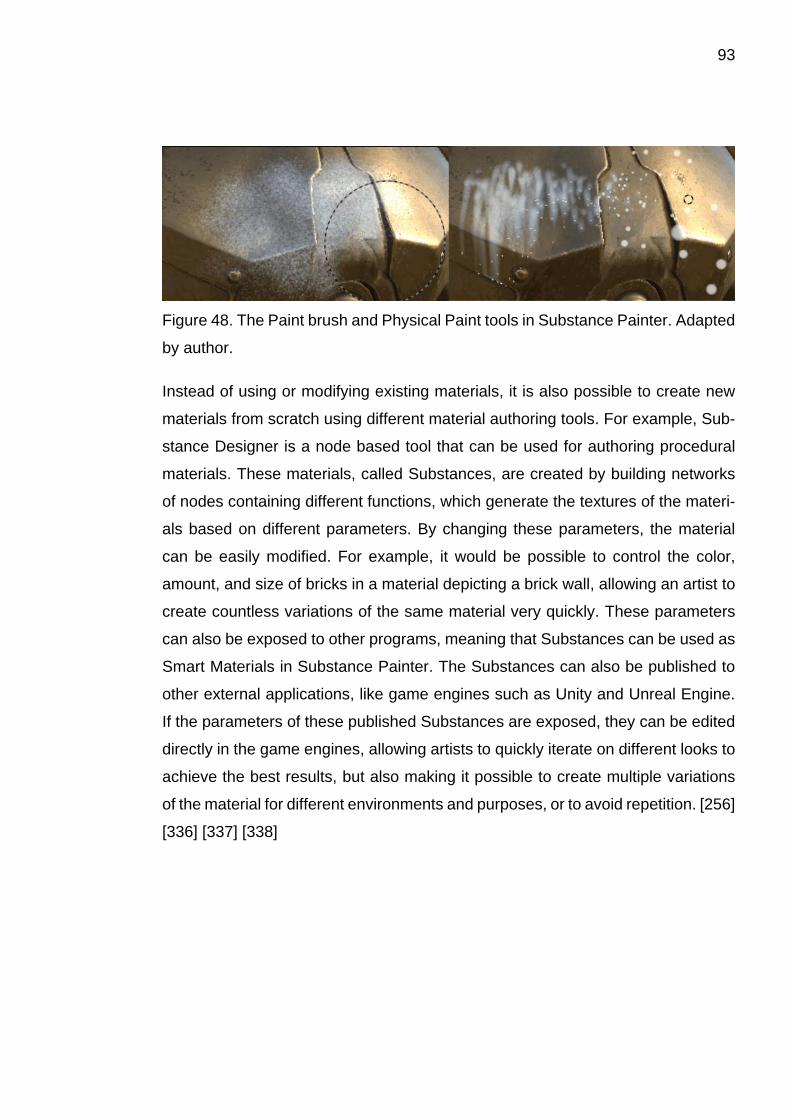
93
Figure 48. The Paint brush and Physical Paint tools in Substance Painter. Adapted
by author.
Instead of using or modifying existing materials, it is also possible to create new
materials from scratch using different material authoring tools. For example, Sub-
stance Designer is a node based tool that can be used for authoring procedural
materials. These materials, called Substances, are created by building networks
of nodes containing different functions, which generate the textures of the materi-
als based on different parameters. By changing these parameters, the material
can be easily modified. For example, it would be possible to control the color,
amount, and size of bricks in a material depicting a brick wall, allowing an artist to
create countless variations of the same material very quickly. These parameters
can also be exposed to other programs, meaning that Substances can be used as
Smart Materials in Substance Painter. The Substances can also be published to
other external applications, like game engines such as Unity and Unreal Engine.
If the parameters of these published Substances are exposed, they can be edited
directly in the game engines, allowing artists to quickly iterate on different looks to
achieve the best results, but also making it possible to create multiple variations
of the material for different environments and purposes, or to avoid repetition. [256]
[336] [337] [338]
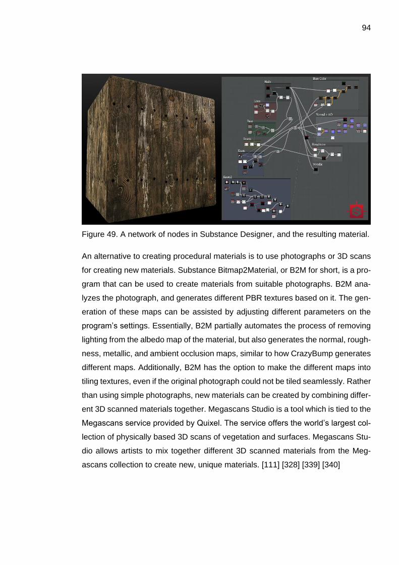
94
Figure 49. A network of nodes in Substance Designer, and the resulting material.
An alternative to creating procedural materials is to use photographs or 3D scans
for creating new materials. Substance Bitmap2Material, or B2M for short, is a pro-
gram that can be used to create materials from suitable photographs. B2M ana-
lyzes the photograph, and generates different PBR textures based on it. The gen-
eration of these maps can be assisted by adjusting different parameters on the
program’s settings. Essentially, B2M partially automates the process of removing
lighting from the albedo map of the material, but also generates the normal, rough-
ness, metallic, and ambient occlusion maps, similar to how CrazyBump generates
different maps. Additionally, B2M has the option to make the different maps into
tiling textures, even if the original photograph could not be tiled seamlessly. Rather
than using simple photographs, new materials can be created by combining differ-
ent 3D scanned materials together. Megascans Studio is a tool which is tied to the
Megascans service provided by Quixel. The service offers the world’s largest col-
lection of physically based 3D scans of vegetation and surfaces. Megascans Stu-
dio allows artists to mix together different 3D scanned materials from the Meg-
ascans collection to create new, unique materials. [111] [328] [339] [340]
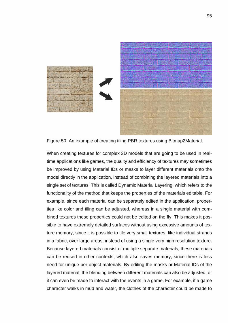
95
Figure 50. An example of creating tiling PBR textures using Bitmap2Material.
When creating textures for complex 3D models that are going to be used in real-
time applications like games, the quality and efficiency of textures may sometimes
be improved by using Material IDs or masks to layer different materials onto the
model directly in the application, instead of combining the layered materials into a
single set of textures. This is called Dynamic Material Layering, which refers to the
functionality of the method that keeps the properties of the materials editable. For
example, since each material can be separately edited in the application, proper-
ties like color and tiling can be adjusted, whereas in a single material with com-
bined textures these properties could not be edited on the fly. This makes it pos-
sible to have extremely detailed surfaces without using excessive amounts of tex-
ture memory, since it is possible to tile very small textures, like individual strands
in a fabric, over large areas, instead of using a single very high resolution texture.
Because layered materials consist of multiple separate materials, these materials
can be reused in other contexts, which also saves memory, since there is less
need for unique per-object materials. By editing the masks or Material IDs of the
layered material, the blending between different materials can also be adjusted, or
it can even be made to interact with the events in a game. For example, if a game
character walks in mud and water, the clothes of the character could be made to
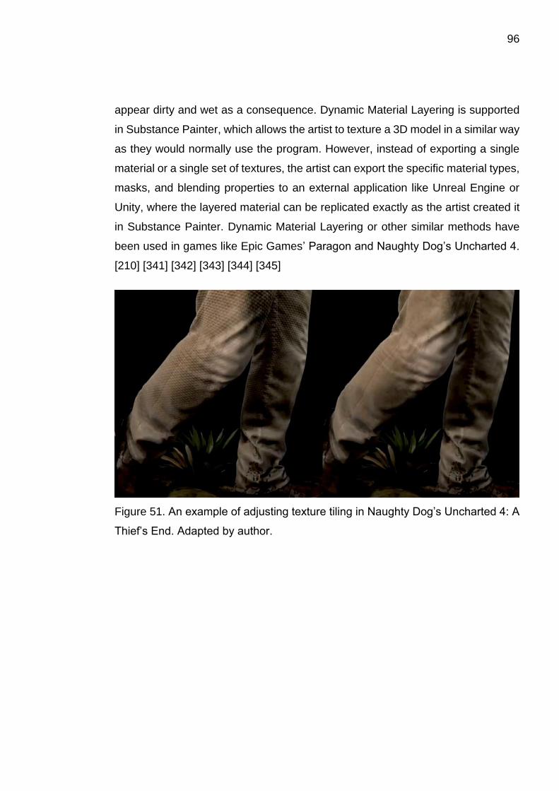
96
appear dirty and wet as a consequence. Dynamic Material Layering is supported
in Substance Painter, which allows the artist to texture a 3D model in a similar way
as they would normally use the program. However, instead of exporting a single
material or a single set of textures, the artist can export the specific material types,
masks, and blending properties to an external application like Unreal Engine or
Unity, where the layered material can be replicated exactly as the artist created it
in Substance Painter. Dynamic Material Layering or other similar methods have
been used in games like Epic Games’ Paragon and Naughty Dog’s Uncharted 4.
[210] [341] [342] [343] [344] [345]
Figure 51. An example of adjusting texture tiling in Naughty Dog’s Uncharted 4: A
Thief’s End. Adapted by author.
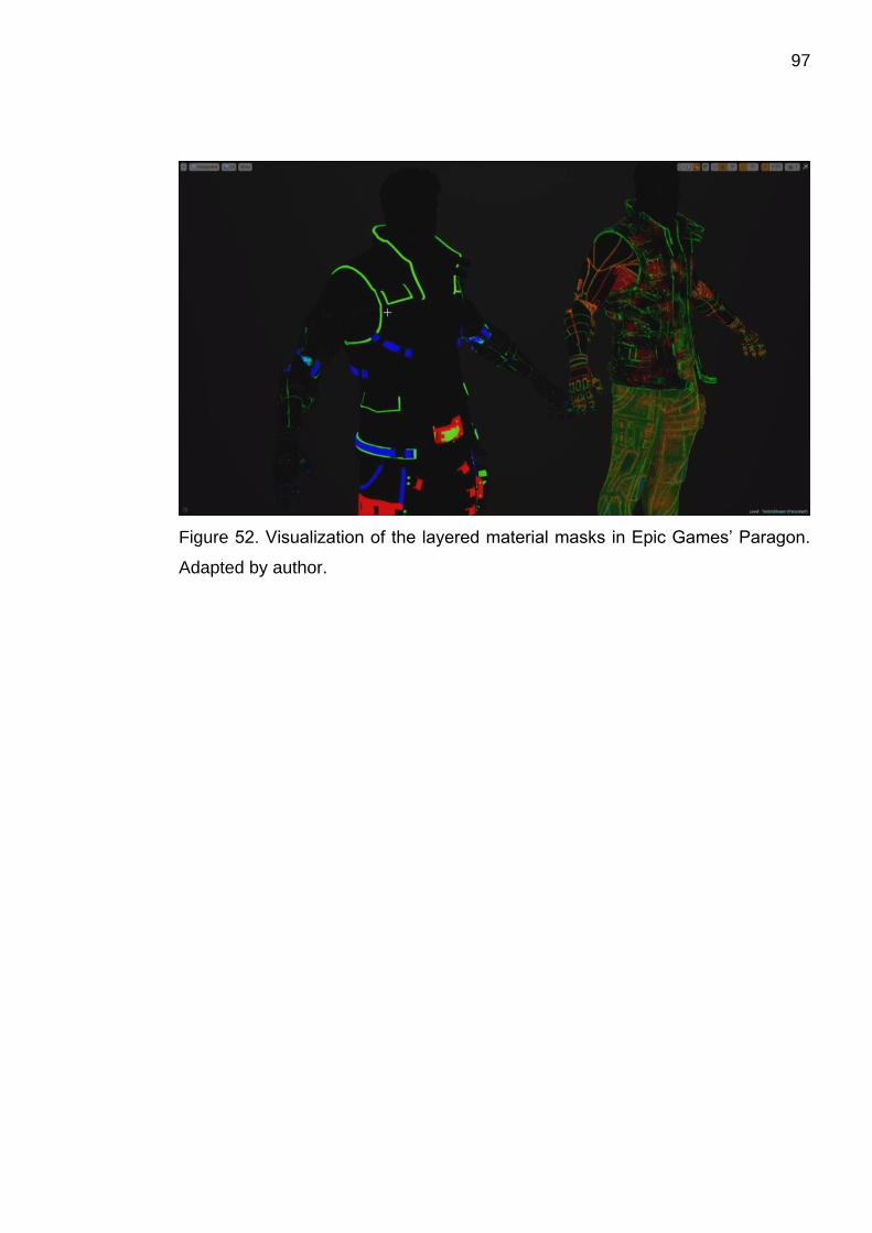
97
Figure 52. Visualization of the layered material masks in Epic Games’ Paragon.
Adapted by author.
98
5 CONCLUSION
The creation of a 3D game character is a complex process, consisting of multiple
stages, each requiring specialized expertise and skills. Therefore, it is no wonder
that the process is often divided among different professionals, each one skilled in
their respective specialization. Additionally, as game productions grow bigger and
more ambitious, new technologies and methods are constantly developed to im-
prove the visuals of games. In order to stay on the cutting edge of game develop-
ment, artists need to constantly learn new principles and methods, as well as the
tools that come with them. Thankfully, modern tools are often more intuitive and
efficient, making it easier for artists to learn and use them, and making the content
creation faster and more efficient. Also, as hardware catches up with the demands
of games’ visuals, artists are gradually freed from the restrictions set by the com-
putational power of devices, allowing for more creative freedom. However, this
does not eliminate the need to first learn the basics, like understanding how differ-
ent aspects of 3D models and textures affect the performance of games, and what
the fundamental principles of different methods and technologies are based on.
Despite the advances in technology and tools, the creation of game characters still
remains a vast and complicated process, and the amount of expertise and skill it
requires can appear especially daunting to small development teams, or individu-
als wishing to enter the game industry.
One of the objectives of this thesis was to create a comprehensive and relatively
detailed description of the complete process of creating 3D game characters for
different types of games, whether the game was intended for mobile devices,
game consoles, or powerful gaming computers. The concepts and methods pre-
sented in the thesis were intended to be understandable even for people not fa-
miliar with game development, which is why many of the concepts were accom-
panied by simple examples. It would be wonderful if this thesis was able to help
other aspiring game artists at the beginning of their journey to the depths of the
rabbit hole that is game development.
99
REFERENCES
[1] Haglund V. CHARACTER DEVELOPMENT AND ITS UTILIZATION FOR CON-
VERGENT MEDIA FORMATS. 2012; Available at: http://www.diva-por-
tal.org/smash/get/diva2:615435/fulltext01.pdf. Accessed 28.10, 2015.
[2] Rollings A, Adams E. Andrew Rollings and Ernest Adams on Game Design. :
New Riders; 2003. Available at: http://bit.ly/1XzCOpg. Accessed 28.10, 2015.
[3] Adams E. Fundamentals of Game Design. Third ed.: New Riders; 2014.
Available at: http://bit.ly/1GxElb9. Accessed 28.10, 2015.
[4] Tillman B. Creative Character Design. : Focal Press; 2011. Available at:
http://bit.ly/1RDK2oc. Accessed 10.3, 2016.
[5] Ash E, Powell M. Game Art Design - Critical Studies: Art Direction 1, Principles
of Character Design. 2014; Available at: http://www.scribd.com/doc/263707847
/Game-Art-Art-Direction-Principles-of-Character-Design. Accessed 10.3, 2016.
[6] Valve Corporation. Dota 2 - Character Art Guide. 2012; Available at: http://me-
dia.steampowered.com/apps/dota2/workshop/Dota2CharacterArtGuide.pdf.
Accessed 10.3, 2016.
[7] Long ZD. Invadingduck Auck! Character Design Part 1: The Silhouette. 2013;
Available at: http://invadingduck.kinja.com/invadingduck-auck-character-design-
part-1-the-silhoue-462360831. Accessed 10.3, 2016.
[8] Spencer S. ZBrush Creature Design: Creating Dynamic Concept Imagery for
Film and Games. : John Wiley & Sons; 2012. Available at: http://me-
dia.wiley.com/product_data/excerpt/38/11180243/1118024338.pdf. Accessed
18.3, 2016.
[9] Clarke J. How to design better creatures. 2014; Available at: http://www.crea-
tivebloq.com/3d/how-design-better-creatures-41411337. Accessed 18.3, 2016.
100
[10] Solarski C. Sponsored Feature: Drawing Basics and Video Game Art: Char-
acter Design. 2014; Available at: http://www.gamasutra.com/view/fea-
ture/178656/sponsored_feature_drawing_basics_.php?page=2. Accessed 21.3,
2016.
[11] Chandler HM. The game production handbook. Third ed.: Jones & Bartlett
Learning; 2013. Available at: http://bit.ly/29I5HRF. Accessed 11.7, 2016.
[12] Novak J. Game Development Essentials. Third ed.: Cengage Learning; 2011.
Available at: http://bit.ly/29Jx0bk. Accessed 11.7, 2016.
[13] Rouse R. Game Design: Theory and Practice. Second ed.: Jones & Bartlett
Learning; 2010. Available at: http://bit.ly/29BXAF3. Accessed 11.7, 2016.
[14] Gross S. Game Development - Story Bible Example. Available at:
http://www.articlecity.com/articles/computers_and_internet/article_4107.shtml.
Accessed 11.7, 2016.
[15] Anhut A. Let’s Get Real About Concept Art. 2014; Available at: http://how-
tonotsuckatgamedesign.com/2014/02/lets-get-real-concept-art/. Accessed 11.7,
2016.
[16] Bowater C. Character Concept Art: From Initial Sketch to Final Design. Avail-
able at: https://www.skillshare.com/classes/design/Character-Concept-Art-From-
Initial-Sketch-to-Final-Design/1310245862/project-guide. Accessed 11.7, 2016.
[17] Masters M. Create 3D Models More Quickly with a Model Sheet. 2015; Avail-
able at: http://blog.digitaltutors.com/create-3D models-3x-faster-with-a-model-
sheet/. Accessed 11.7, 2016.
[18] Oliver JG. Model Sheets 101 - Part 1. 2010; Available at: http://charac-
terdesignnotes.blogspot.fi/2010/12/model-sheets-101.html. Accessed 11.7, 2016.

101
[19] Oliver JG. Model Sheets 101 - Part 2. 2010; Available at: http://charac-
terdesignnotes.blogspot.fi/2010/12/model-sheets-101-part-2.html. Accessed
11.7, 2016.
[20] Slick J. What is Concept Sculpting?. 2012; Available
at: http://3d.about.com/od/Creating-3D-The-CG-Pipeline/tp/What-Is-Concept-
Sculpting.htm. Accessed 26.7, 2016.
[21] Masters M. How to Setup Reference Images Easily in 3ds Max. 2014; Availa-
ble at: http://blog.digitaltutors.com/setup-reference-images-easily-3ds-max/. Ac-
cessed 3.8, 2016.
[22] MachineDesign.com. Basics of Solid Modeling. 2013; Available at: http://ma-
chinedesign.com/site-files/machinedesign.com/files/uploads/2013/08/SolidMod-
eling.pdf. Accessed 3.8, 2016.
[23] Tutorial45.com. What is AutoCAD actually Used for? 2015; Available
at: http://tutorial45.com/what-is-autocad-used-for/. Accessed 3.8, 2016.
[24] Digital-Tutors. Key 3D Modeling Terminology Beginners Need to Understand.
2013; Available at: http://blog.digitaltutors.com/basic-3d-modeling-terminology/.
Accessed 3.8, 2016.
[25] Scratchapixel. Introduction to Shading - Normals, Vertex Normals and Facing
Ratio. 2014; Available at: http://www.scratchapixel.com/lessons/3d-basic-render-
ing/introduction-to-shading/shading-normals. Accessed 3.8, 2016.
[26] Slick J. 7 Common Modeling Techniques for Film and Games. 2016; Available
at: http://3d.about.com/od/3d-101-The-Basics/a/Introduction-To-3d-Modeling-
Techniques.htm. Accessed 3.8, 2016.
[27] Slick J. Polygonal 3D Modeling - Common Box and Edge Modeling Work-
flows. 2016; Available at: http://3d.about.com/od/Creating-3D-The-CG-Pipe-
line/tp/Polygonal-3d-Modeling-Common-Box-And-Edge-Modeling-Work-
flows.htm. Accessed 3.8, 2016.

102
[28] Blender Documentation Team. Blender 2.78 Manual: Modifiers. 2016; Availa-
ble at: https://docs.blender.org/manual/en/dev/modeling/modifiers/introduc-
tion.html. Accessed 20.5, 2017
[29] Williamson J. Modeling with Modifiers: About. 2017; Available
at: https://cgcookie.com/course/modeling-with-modifiers/#about. Accessed 20.5,
2017
[30] Autodesk Inc. 3ds Max 2017 Help: Modifiers. 2017; Available
at: https://knowledge.autodesk.com/support/3ds-max/learn-ex-
plore/caas/CloudHelp/cloudhelp/2017/ENU/3DSMax/files/GUID-79998C44-
22AA-4485-9608-51630079E5A7-htm.html. Accessed 20.5, 2017
[31] Blender Documentation Team. Blender 2.78 Manual: Mirror Modifier. 2016;
Available at: https://docs.blender.org/manual/en/dev/modeling/modifiers/gener-
ate/mirror.html. Accessed 20.5, 2017
[32] Autodesk Inc. 3ds Max 2017 Help: Mirror Modifier. 2017; Available
at: https://knowledge.autodesk.com/support/3ds-max/learn-ex-
plore/caas/CloudHelp/cloudhelp/2017/ENU/3DSMax/files/GUID-E8C13475-
56CF-4B85-A26D-91CF5764550E-htm.html. Accessed 20.5, 2017
[33] Autodesk Inc. 3ds Max 2017 Help: Symmetry Modifier. 2017; Available
at: https://knowledge.autodesk.com/support/3ds-max/learn-ex-
plore/caas/CloudHelp/cloudhelp/2017/ENU/3DSMax/files/GUID-EB0B7B9B-
117D-4CC3-A966-A3E007E0C68A-htm.html. Accessed 20.5, 2017
[34] Blender Documentation Team. Blender 2.78 Manual: Simple Deform Modifier.
2016; Available at: https://docs.blender.org/manual/en/dev/modeling/modifi-
ers/deform/simple_deform.html. Accessed 20.5, 2017
[35] Autodesk Inc. 3ds Max 2017 Help: Bend Modifier. 2017; Available
at: https://knowledge.autodesk.com/support/3ds-max/learn-ex-
plore/caas/CloudHelp/cloudhelp/2017/ENU/3DSMax/files/GUID-D9F88C33-
8272-4463-A886-7FBAC9A17B85-htm.html. Accessed 20.5, 2017

103
[36] Autodesk Inc. 3ds Max 2017 Help: Twist Modifier. 2017; Available
at: https://knowledge.autodesk.com/support/3ds-max/learn-ex-
plore/caas/CloudHelp/cloudhelp/2017/ENU/3DSMax/files/GUID-0AD7CE08-
9992-4E49-BA11-672DEA3B13CF-htm.html. Accessed 20.5, 2017
[37] Blender Documentation Team. Blender 2.78 Manual: Subdivision Surface
Modifier. 2016; Available at: https://docs.blender.org/manual/en/dev/model-
ing/modifiers/generate/subsurf.html. Accessed 20.5, 2017
[38] Sharp B. Subdivision Surface Theory. 2000; Available at: http://www.gamasu-
tra.com/view/feature/131585/subdivision_surface_theory.php?print=1. Accessed
20.5, 2017
[39] Blender Documentation Team. Blender 2.78 Manual: Multiresolution Modifier.
2016; Available at: https://docs.blender.org/manual/en/dev/modeling/modifi-
ers/generate/multiresolution.html. Accessed 20.5, 2017
[40] Autodesk Inc. 3ds Max 2016 Help: MeshSmooth modifier. 2016; Available
at: http://help.autodesk.com/view/3DSMAX/2016/ENU/?guid=GUID-D204B817-
8B87-42FF-B152-0E360D0035A2. Accessed 20.5, 2017
[41] Autodesk Inc. 3ds Max 2016 Help: TurboSmooth modifier. 2016; Available
at: https://knowledge.autodesk.com/support/3ds-max/learn-ex-
plore/caas/CloudHelp/cloudhelp/2016/ENU/3DSMax/files/GUID-EA8FF838-
B197-4565-9A85-71CE93DA4F68-htm.html. Accessed 20.5, 2017
[42] Autodesk Inc. 3ds Max 2015 Help: OpenSubdiv modifier. 2015; Available
at: http://help.autodesk.com/view/3DSMAX/2015/ENU/?guid=GUID-AC9DDAB2-
52E4-482A-B245-F5C30CC45544. Accessed 20.5, 2017
[43] Autodesk Inc. 3ds Max 2016 Help: Subdivide Modifier (Object Space). 2016;
Available at: http://help.autodesk.com/view/3DSMAX/2016/ENU/?guid=GUID-
67E7E333-585A-4753-8A3A-FFD4A69957A6. Accessed 20.5, 2017

104
[44] Autodesk Inc. 3ds Max 2016 Help: Tessellate modifier. 2016; Available
at: http://help.autodesk.com/view/3DSMAX/2016/ENU/?guid=GUID-C0C572AA-
9F42-4AB0-8123-DAB75817690D. Accessed 20.5, 2017
[45] Autodesk Inc. 3ds Max 2015 Help: HSDS Modifier. 2015; Available
at: http://help.autodesk.com/view/3DSMAX/2015/ENU/?guid=GUID-E7312BB6-
AB50-4328-8855-64AD828CAEC5. Accessed 20.5, 2017
[46] Polycount Wiki. Normal Map Modeling. 2016; Available at: http://wiki.poly-
count.com/wiki/Normal_Map_Modeling. Accessed 20.5, 2017
[47] Slick J. Why are Film Effects So Much Better Than Video Game Graphics?.
2013; Available at: http://3d.about.com/od/A-Guide-To-3D-Software/tp/Why-Are-
Film-Effects-So-Much-Better-Than-Video-Game-Graphics.htm. Accessed 3.8,
2016.
[48] Masters M. What's the Difference? A Comparison of Modeling for Games and
Modeling for Movies. 2014; Available at: http://blog.digitaltutors.com/whats-the-dif-
ference-a-comparison-of-modeling-for-games-and-modeling-for-movies/. Ac-
cessed 3.8, 2016.
[49] Schneider T. A COMPREHENSIVE HISTORY OF LOW-POLY ART, PT. 1.
2014; Available at: https://killscreen.com/articles/poly-generational/. Accessed
26.8, 2016.
[50] Polycount Wiki. Polygon Count. 2016; Available at: http://wiki.polycount.com
/wiki/Polygon_Count. Accessed 3.8, 2016.
[51] Nelva G. inFAMOUS: Second Son’s Characters are 120,000 Polygons; 11
Million Rendered Regularly by the Engine. 2014; Available at: http://www.du-
alshockers.com/2014/04/14/infamous-second-sons-characters-are-120000-poly-
gons-11-million-rendered-regularly-by-the-engine/. Accessed 3.8, 2016.
[52] Polycount Wiki. Topology. 2015; Available at: http://wiki.poly-
count.com/wiki/Topology. Accessed 5.8, 2016.
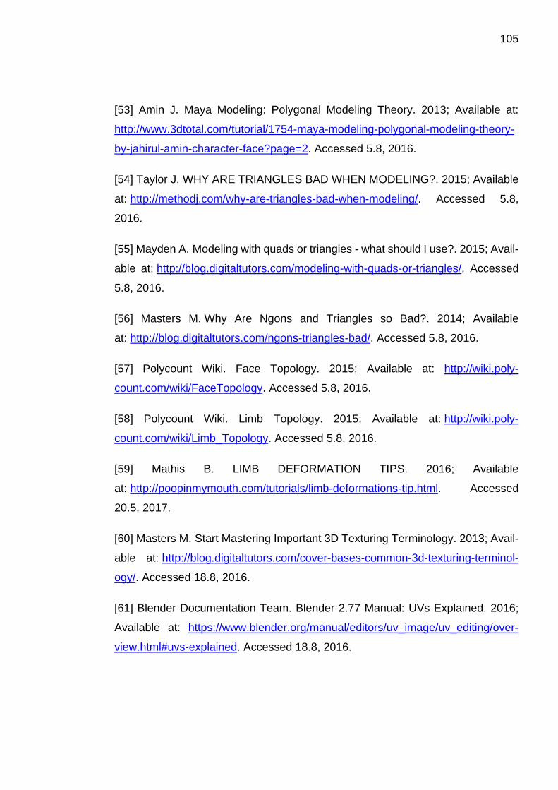
105
[53] Amin J. Maya Modeling: Polygonal Modeling Theory. 2013; Available at:
http://www.3dtotal.com/tutorial/1754-maya-modeling-polygonal-modeling-theory-
by-jahirul-amin-character-face?page=2. Accessed 5.8, 2016.
[54] Taylor J. WHY ARE TRIANGLES BAD WHEN MODELING?. 2015; Available
at: http://methodj.com/why-are-triangles-bad-when-modeling/. Accessed 5.8,
2016.
[55] Mayden A. Modeling with quads or triangles - what should I use?. 2015; Avail-
able at: http://blog.digitaltutors.com/modeling-with-quads-or-triangles/. Accessed
5.8, 2016.
[56] Masters M. Why Are Ngons and Triangles so Bad?. 2014; Available
at: http://blog.digitaltutors.com/ngons-triangles-bad/. Accessed 5.8, 2016.
[57] Polycount Wiki. Face Topology. 2015; Available at: http://wiki.poly-
count.com/wiki/FaceTopology. Accessed 5.8, 2016.
[58] Polycount Wiki. Limb Topology. 2015; Available at: http://wiki.poly-
count.com/wiki/Limb_Topology. Accessed 5.8, 2016.
[59] Mathis B. LIMB DEFORMATION TIPS. 2016; Available
at: http://poopinmymouth.com/tutorials/limb-deformations-tip.html. Accessed
20.5, 2017.
[60] Masters M. Start Mastering Important 3D Texturing Terminology. 2013; Avail-
able at: http://blog.digitaltutors.com/cover-bases-common-3d-texturing-terminol-
ogy/. Accessed 18.8, 2016.
[61] Blender Documentation Team. Blender 2.77 Manual: UVs Explained. 2016;
Available at: https://www.blender.org/manual/editors/uv_image/uv_editing/over-
view.html#uvs-explained. Accessed 18.8, 2016.
106
[62] Blender Documentation Team. Blender 2.77 Manual: UV Mapping a Mesh.
2016; Available at: https://www.blender.org/manual/editors/uv_image/uv_edit-
ing/unwrapping.html#uv-mapping-a-mesh. Accessed 18.8, 2016.
[63] Nobel-Jørgensen M. Procedural generated mesh in Unity part 2 with UV map-
ping. 2011; Available at: https://blog.nobel-joergensen.com/2011/04/05/proce-
dural-generated-mesh-in-unity-part-2-with-uv-mapping/. Accessed 18.8, 2016.
[64] Autodesk Inc. Maya LT Help: Cylindrical UV Mapping. 2015; Available
at: https://knowledge.autodesk.com/support/maya-lt/learn-ex-
plore/caas/CloudHelp/cloudhelp/2015/ENU/MayaLT/files/Mapping-UVs-Cylindri-
cal-UV-mapping-htm.html. Accessed 18.8, 2016.
[65] Autodesk Inc. Maya LT Help: Spherical UV Mapping. 2015; Available
at: https://knowledge.autodesk.com/support/maya-lt/learn-ex-
plore/caas/CloudHelp/cloudhelp/2015/ENU/MayaLT/files/Mapping-UVs-Spheri-
cal-UV-mapping-htm.html. Accessed 18.8, 2016.
[66] Autodesk Inc. Maya LT Help: Planar UV Mapping. 2015; Available
at: https://knowledge.autodesk.com/support/maya-lt/learn-ex-
plore/caas/CloudHelp/cloudhelp/2015/ENU/MayaLT/files/Mapping-UVs-Planar-
UV-mapping-htm.html. Accessed 18.8, 2016.
[67] Masters M. Understanding UVs - Love Them or Hate Them, They're Essential
to Know. 2015; Available at: http://blog.digitaltutors.com/understanding-uvs-love-
them-or-hate-them-theyre-essential-to-know/. Accessed 13.9, 2016.
[68] Polycount.com forums user RedRogueXIII. UV Unwrapping Best Practice
Factors & Priorities. 2011; Available at: http://polycount.com/discussion/85675/uv-
unwrapping-best-practice-factors-priorities. Accessed 18.8, 2016.
[69] Polycount.com forums user Eric Chadwick. UV Unwrapping Best Practice
Factors & Priorities. 2011; Available at: http://polycount.com/discussion/85675/uv-
unwrapping-best-practice-factors-priorities. Accessed 18.8, 2016.
107
[70] Polycount Wiki. Edge Padding. 2015; Available at: http://wiki.poly-
count.com/wiki/EdgePadding. Accessed 18.8, 2016.
[71] Autodesk Inc. Maya LT Help: Automatic UV Mapping. 2015; Available
at: https://knowledge.autodesk.com/support/maya-lt/learn-ex-
plore/caas/CloudHelp/cloudhelp/2015/ENU/MayaLT/files/Mapping-UVs-Auto-
matic-UV-mapping-htm.html. Accessed 18.8, 2016.
[72] Schoenmaker H. TexTools. 2010; Available at: http://www.renderhjs.net/tex-
tools/. Accessed 18.8, 2016.
[73] headus (metamorphosis) Pty Ltd. Welcome to headus UVLayout. 2010; Avail-
able at: https://www.uvlayout.com/. Accessed 18.8, 2016.
[74] Pullin Shapes. Roadkill UV Tool. 2013; Available at: http://www.pullin-
shapes.co.uk/page8.htm. Accessed 18.8, 2016.
[75] Piranha Bytes Distribution UG&Co KG. IPackThat. 2016; Available
at: http://store.steampowered.com/app/363020/. Accessed 18.8, 2016.
[76] 3d-io. Unwrella – Optimal Automatic Unwrapping. 2015; Available
at: http://www.unwrella.com/. Accessed 18.8, 2016.
[77] Polycount Wiki. Texturing. 2016; Available at: http://wiki.poly-
count.com/wiki/Texture. Accessed 13.9, 2016.
[78] Polycount Wiki. Texture types. 2015; Available at: http://wiki.poly-
count.com/wiki/Texture_types. Accessed 13.9, 2016.
[79] Polycount Wiki. Diffuse map. 2014; Available at: http://wiki.poly-
count.com/wiki/Diffuse_map. Accessed 13.9, 2016.
[80] Maximov A. Physically Based Texturing for Artists. 2014; Available
at: http://artisaverb.info/PBT.html. Accessed 13.9, 2016.
108
[81] Wilson J. Tutorial: Physically Based Rendering, And You Can Too!. 2014;
Available at: http://www.marmoset.co/toolbag/learn/pbr-practice. Accessed 13.9,
2016.
[82] Polycount Wiki. Specular color map. 2014; Available at: http://wiki.poly-
count.com/wiki/Specular_color_map. Accessed 13.9, 2016.
[83] Polycount Wiki. Specular gloss map. 2014; Available at: http://wiki.poly-
count.com/wiki/Specular_gloss_map. Accessed 13.9, 2016.
[84] Russel E. Elliminate Texture Confusion: Bump, Normal and Displacement
Maps. 2015; Available at: http://blog.digitaltutors.com/bump-normal-and-displace-
ment-maps/. Accessed 13.9, 2016.
[85] Polycount Wiki. Normal map. 2016; Available at: http://wiki.poly-
count.com/wiki/Normal_map. Accessed 13.9, 2016.
[86] Unity Technologies. Unity Manual: Normal map (Bump mapping). 2016; Avail-
able at: https://docs.unity3d.com/Manual/StandardShaderMaterialParameterNor-
malMap.html. Accessed 15.9, 2016.
[87] Polycount Wiki. Displacement map. 2015; Available at: http://wiki.poly-
count.com/wiki/Displacement_map. Accessed 13.9, 2016.
[88] NVIDIA Corporation. DirectX 11 Tessellation. 2010; Available
at: http://www.nvidia.com/object/tessellation.html. Accessed 13.9, 2016.
[89] Burke S. Defining Tessellation and Its Impact on Game Graphics (with Epic
Games). 2015; Available at: http://www.gamersnexus.net/guides/1936-what-is-
tessellation-game-graphics. Accessed 13.9, 2016.
[90] Polycount Wiki. Parallax map. 2015; Available at: http://wiki.poly-
count.com/wiki/Parallax_map. Accessed 13.9, 2016.
109
[91] Unity Technologies. Unity Manual: Heightmap. 2016; Available at:
https://docs.unity3d.com/Manual/StandardShaderMaterialParameterHeight-
Map.html. Accessed 15.9, 2016.
[92] Polycount Wiki. Transparency map. 2015; Available at: http://wiki.poly-
count.com/wiki/Transparency_map. Accessed 13.9, 2016.
[93] Unity Technologies. Unity Manual: Albedo Color and Transparency. 2016;
Available at: https://docs.unity3d.com/Manual/StandardShaderMaterialParame-
terAlbedoColor.html. Accessed 15.9, 2016.
[94] Han J. 3D Graphics for Game Programming. : CRC Press; 2011. Available at:
http://bit.ly/2c9d2Kk. Accessed 14.9, 2016.
[95] Polycount Wiki. Ambient occlusion map. 2015; Available at: http://wiki.poly-
count.com/wiki/Ambient_occlusion_map. Accessed 14.9, 2016.
[96] Masters M. Understanding Ambient Occlusion. 2015; Available
at: http://blog.digitaltutors.com/understanding-ambient-occlusion/. Accessed 14.9,
2016.
[97] Valve Corporation. Dota 2 Workshop - Color Texture Light Baking. 2015;
Available at: https://support.steampowered.com/kb/8700-SJKN-4322/dota-2-
character-texture-guide. Accessed 14.9, 2016.
[98] Unity Technologies. Unity Manual: Occlusion map. 2016; Available at:
https://docs.unity3d.com/Manual/StandardShaderMaterialParameterOcclu-
sionMap.html. Accessed 15.9, 2016.
[99] Polycount Wiki. Emissive map. 2014; Available at: http://wiki.poly-
count.com/wiki/Emissive_map. Accessed 14.9, 2016.
[100] Unity Technologies. Unity Manual: Emission. 2016; Available
at: https://docs.unity3d.com/Manual/StandardShaderMaterialParameterEmis-
sion.html. Accessed 15.9, 2016.
110
[101] Unity Technologies. Unity Manual: Secondary Maps (Detail Maps) & Detail
Mask. 2016; Available at: https://docs.unity3d.com/Manual/StandardShaderMa-
terialParameterDetail.html. Accessed 15.9, 2016.
[102] Epic Games Inc. Unreal Engine 4 Documentation - Material Editor - How To
add Detail Textures. 2015; Available at: https://docs.unrealengine.com/lat-
est/INT/Engine/Rendering/Materials/HowTo/DetailTexturing/. Accessed 15.9,
2016.
[103] Silverman D. 3D Primer for Game Developers: An Overview of 3D Modeling
in Games. 2013; Available at: https://gamedevelopment.tutsplus.com/articles/3d-
primer-for-game-developers-an-overview-of-3d-modeling-in-games--gamedev-
5704. Accessed 20.5, 2017.
[104] Paquette A. Computer Graphics for Artists II: Environments and Characters.
: Springer Science & Business Media; 2009. Available at: http://bit.ly/2pFTAH3.
Accessed 20.5, 2017.
[105] Slick J. Surfacing 101 - The Basics of Texture Mapping. 2016; Available
at: https://www.lifewire.com/texture-mapping-1956. Accessed 20.5, 2017.
[106] Autodesk Inc. Mudbox 2017 Help: Painting overview. 2017; Available
at: http://docs.autodesk.com/MBXPRO/2017/ENU/#!/url=./files/GUID-6E09FE84-
38FE-40F4-AAE9-2A03BA3483D5.htm. Accessed 20.5, 2017.
[107] Hawkins R. Vertex 1. 2012; Available at: http://artbypapercut.com/. Ac-
cessed 1.10, 2016.
[108] Hawkins R. Vertex 2. 2014; Available at: http://artbypapercut.com/. Ac-
cessed 1.10, 2016.
[109] Clark R. CrazyBump. 2016; Available at: http://www.crazybump.com/. Ac-
cessed 2.10, 2016.
111
[110] Kolasinski K. AwesomeBump - About. 2016; Available at: http://awesome-
bump.besaba.com/about/. Accessed 2.10, 2016.
[111] Allegorithmic Inc. Substance B2M. 2016; Available at: https://www.allegorith-
mic.com/products/bitmap2material. Accessed 2.10, 2016.
[112] Hawkins R. Vertex 3. 2015; Available at: http://artbypapercut.com/. Ac-
cessed 1.10, 2016.
[113] Polycount Wiki. Texture Baking. 2016; Available at: http://wiki.poly-
count.com/wiki/Texture_Baking. Accessed 1.10, 2016.
[114] Pixologic Inc. ZBrush 4R7 Online Documentation: Texture Maps. 2016;
Available at: http://docs.pixologic.com/user-guide/3d-modeling/painting-your-
model/texture-maps/. Accessed 2.10, 2016.
[115] Autodesk Inc. 3ds Max 2016 Help: Texture Elements to Bake. 2016; Availa-
ble at: http://help.autodesk.com/view/3DSMAX/2016/ENU/?guid=GUID-
B1597F7A-EAF4-4197-BB7C-42A90C12BBCB. Accessed 2.10, 2016.
[116] KatsBits. Make Better Textures For Games, 'Power Of Two' & Proper Image
Dimensions. 2015; Available at: https://www.katsbits.com/tutorials/textures/make-
better-textures-correct-size-and-power-of-two.php. Accessed 25.5, 2017.
[117] McDermott W. Creating 3D Game Art for the IPhone with Unity: Featuring
Modo and Blender Pipelines. : Taylor & Francis; 2010. Available at:
http://bit.ly/2rdx9hY. Accessed 25.5, 2017.
[118] Mathis B. TRUE RESOLUTION VS RESIZING. 2016; Available
at: http://poopinmymouth.com/tutorials/resize-paper.html.
[119] Slick J. What is Rigging? - Preparing a 3D Model For Animation. 2016; Avail-
able at: https://www.lifewire.com/what-is-rigging-2095. Accessed 25.5, 2017.

112
[120] Pluralsight LLC. Key 3D Rigging Terms to Get You Moving. 2014; Available
at: https://www.pluralsight.com/blog/film-games/key-rigging-terms-get-moving.
Accessed 25.5, 2017.
[121] Autodesk Inc. Maya 2016 Help: Joints and bones. 2016; Available
at: http://help.autodesk.com/view/MAYAUL/2016/ENU/?guid=GUID-1B59334F-
2605-44C3-B584-A55B239A2CBE. Accessed 25.5, 2017.
[122] Autodesk Inc. 3ds Max 2016 Help: Creating a CATRig. 2016; Available
at: http://help.autodesk.com/view/3DSMAX/2016/ENU/?guid=GUID-B28DB94E-
2DD7-442A-96C1-53CE40998393. Accessed 25.5, 2017.
[123] Autodesk Inc. Maya 2016 Help: Driven keys. 2016; Available
at: http://help.autodesk.com/view/MAYAUL/2016/ENU/?guid=GUID-2C048635-
CDD2-4CF7-820D-A032204C8CE8. Accessed 25.5, 2017.
[124] Autodesk Inc. Maya Mondays, Set Driven Key. 2014; [YouTube Video]: 5:00-
8:12 Available at: https://youtu.be/REBPuOMKEuM?t=300. Accessed 25.5, 2017.
[125] Zwerman S, Okun JA. Visual Effects Society Handbook: Workflow and Tech-
niques. First ed.: Focal Press; 2010. Available at: http://bit.ly/2rwMABh. Accessed
25.5, 2017.
[126] Autodesk Inc. Maya 2017 Help: Deformation effects. 2017; Available
at: http://help.autodesk.com/view/MAYAUL/2017/ENU/?guid=GUID-B1AB118B-
D620-4A74-88AA-11E8569D0E60. Accessed 25.5, 2017.
[127] Leonard R, McKay P. Maya Deformers: Facial Rigging. 2015; Available
at: https://github.com/terminalstderr/ChernoffFaceAnimator/wiki/Maya-Deform-
ers:-Facial-Rigging. Accessed 25.5, 2017.
[128] Autodesk Inc. Maya 2017 Help: Create blend shapes using multiple target
objects. 2017; Available at: http://help.autodesk.com/view/MA-
YAUL/2017/ENU/?guid=GUID-42114F0D-8F16-4365-A52C-E0FD70F40852. Ac-
cessed 25.5, 2017.

113
[129] Gay C. OverMorpher PoseSpace Workflow 1. 2016; [Vimeo Video]. Available
at: https://vimeo.com/158316932. Accessed 25.5, 2017.
[130] Autodesk Inc. Maya 2017 Help: Cluster deformer. 2017; Available
at: http://help.autodesk.com/view/MAYAUL/2017/ENU/?guid=GUID-B7C96FEA-
C415-4927-8E02-396F0E837DE2. Accessed 25.5, 2017.
[131] Autodesk Inc. Maya 2017 Help: Wrap deformer. 2017; Available
at: http://help.autodesk.com/view/MAYAUL/2017/ENU/?guid=GUID-B98E74F5-
6965-41B1-BBF8-471FB2FAD7EC. Accessed 25.5, 2017.
[132] Autodesk Inc. Maya 2017 Help: Maya Muscle. 2017; Available
at: http://help.autodesk.com/view/MAYAUL/2017/ENU/?guid=GUID-90B5E302-
8DAA-4780-BCD6-FB9C60FF9E05. Accessed 25.5, 2017.
[133] Autodesk Inc. 3ds Max 2016 Help: Working With Muscles. 2016; Available
at: http://help.autodesk.com/view/3DSMAX/2016/ENU/?guid=GUID-49276514-
378F-4FDA-9B3B-E31E332DD966. Accessed 25.5, 2017.
[134] Autodesk Inc. 3ds Max 2016 Help: Muscle Strand. 2016; Available
at: http://help.autodesk.com/view/3DSMAX/2016/ENU/?guid=GUID-A6CDE7D5-
37DB-4C0F-9F2F-03FF04B807BA. Accessed 25.5, 2017.
[135] Autodesk Inc. Autodesk Maya 2011: Maya Muscle. 2010; Available
at: http://download.autodesk.com/us/support/files/muscle.pdf. Accessed 25.5,
2017.
[136] Kivistö J. Real-Time Muscle Animation. 2012; Available
at: http://urn.fi/URN:NBN:fi:amk-2012060712109. Accessed 25.5, 2017.
[137] Evans C. Multi-Resolution Facial Rigging. 2014; Available
at: http://www.chrisevans3d.com/pub_blog/multi-resolution-facial-rigging/. Ac-
cessed 25.5, 2017.
114
[138] Failes I. The tech of Crytek’s Ryse: Son of Rome. 2014; Available
at: https://www.fxguide.com/featured/the-tech-of-cryteks-ryse-son-of-rome/. Ac-
cessed 25.5, 2017.
[139] Autodesk Inc. Maya 2017 Help: Skinning your character. 2017; Available
at: http://help.autodesk.com/view/MAYAUL/2017/ENU/?guid=GUID-EFE68C08-
9ADA-4355-8203-5D1D109DCC82. Accessed 25.5, 2017.
[140] Autodesk Inc. 3ds Max 2016 Help: About the Skin Modifier. 2016; Available
at: http://help.autodesk.com/view/3DSMAX/2016/ENU/?guid=GUID-5C7FB2B6-
5CD6-461D-8E56-03D153E80145. Accessed 25.5, 2017.
[141] Autodesk Inc. Maya 2017 Help: Smooth skinning. 2017; Available
at: http://help.autodesk.com/view/MAYAUL/2017/ENU/?guid=GUID-11007900-
329F-40ED-9C38-BE4DB5C39832. Accessed 25.5, 2017.
[142] Autodesk Inc. Maya 2017 Help: Paint skin weights. 2017; Available
at: http://help.autodesk.com/view/MAYAUL/2017/ENU/?guid=GUID-7D773C38-
F9CF-4141-8ADD-4E0454838BB7. Accessed 25.5, 2017.
[143] Pluralsight LLC. Rigging Guideline for the Artist: What's Important for a Good
Rig? 2014; Available at: https://www.pluralsight.com/blog/film-games/rigging-
guideline-artist-whats-important-good-rig. Accessed 25.5, 2017.
[144] Autodesk Inc. 3ds Max 2016 Help: Applying Manipulation Gizmos. 2016;
Available at: http://help.autodesk.com/view/3DSMAX/2016/ENU/?guid=GUID-
B647ABC5-3078-4774-BF70-46DB2AD2ACE3. Accessed 25.5, 2017.
[145] Pluralsight LLC. Break Things to Make Them Better: Stress Testing Your
Rigs. 2015; Available at: https://www.pluralsight.com/blog/film-games/break-
things-make-better-stress-testing-rigs. Accessed 25.5, 2017.

115
[146] Autodesk Inc. 3ds Max 2016 Help: Getting Started: Rigging with CATRigs.
2016; Available at: http://help.auto-
desk.com/view/3DSMAX/2016/ENU/?guid=GUID-BB87B15F-7A2C-4C6F-AADF-
3A5F2962549E. Accessed 25.5, 2017.
[147] Autodesk Inc. Maya 2016 Help: Create an automatic character rig for a mesh.
2016; Available at: http://help.autodesk.com/view/MA-
YAUL/2016/ENU/?guid=GUID-6CAEA6C2-D4F9-422D-8E0F-522171B47C35.
Accessed 25.5, 2017.
[148] Anzovin Studio Inc. Anzovin Rig Tools. 2016; Available
at: http://www.anzovin.com/art/. Accessed 25.5, 2017.
[149] Habas L. LH | Auto-Rig v1.09. 2016; Available at: http://cg-anima-
tion.com/en/tools/auto-rig-eng.html. Accessed 25.5, 2017.
[150] Veber L. Blender Market - Auto-Rig Pro. 2017; Available
at: https://www.blendermarket.com/products/auto-rig-pro. Accessed 25.5, 2017.
[151] Mixamo Inc. AUTO-RIGGER (PREVIEW) Rig a character in the time it takes
to get a cup of coffee. 2016; Available at: https://www.mixamo.com/auto-rigger.
Accessed 25.5, 2017.
[152] Autodesk Inc. 3ds Max 2016 Help: Time Slider. 2016; Available
at: http://help.autodesk.com/view/3DSMAX/2016/ENU/?guid=GUID-A612A8B5-
5F68-4B8F-9A4C-4E60A746E1CB. Accessed 25.5, 2017.
[153] Autodesk Inc. Maya 2017 Help: Keyframe Animation. 2017; Available
at: http://help.autodesk.com/view/MAYAUL/2017/ENU/?guid=GUID-66ED4510-
CC1B-4E11-918B-B7DC447E38A7. Accessed 25.5, 2017.
[154] Autodesk Inc. 3ds Max 2016 Help: Animation Concepts. 2016; Available
at: http://help.autodesk.com/view/3DSMAX/2016/ENU/?guid=GUID-ADB8D6B2-
392D-49BF-B941-1414FBD97202. Accessed 25.5, 2017.
116
[155] Autodesk Inc. Maya 2017 Help: Graph Editor. 2017; Available
at: http://help.autodesk.com/view/MAYAUL/2017/ENU/?guid=GUID-6D38EAEA-
6032-471E-BD0E-54A74D4443C0. Accessed 25.5, 2017.
[156] Valve Corporation. Vertex animation - Valve Developer Community. 2014;
Available at: https://developer.valvesoftware.com/wiki/Vertex_animation. Ac-
cessed 25.5, 2017.
[157] Khalembakov A. Cloth Simulation Workflow. 2017; Available
at: https://www.blend4web.com/en/community/article/48/. Accessed 25.5, 2017.
[158] Enqvist H. The Secrets Of Cloth Simulation In Alan Wake. 2010; Available
at: http://www.gamasutra.com/view/feature/132771/the_secrets_of_cloth_simula-
tion_in_.php?print=1. Accessed 25.5, 2017.
[159] Facepunch forums user Gamerman12. Baking Cloth Physics from Maya to
Source Filmmaker. 2013; Available at: https://face-
punch.com/showthread.php?t=1251298. Accessed 25.5, 2017.
[160] PhysXInfo.com. Clothing simulation solutions for games. 2011; Available
at: http://physxinfo.com/articles/?page_id=389. Accessed 25.5, 2017.
[161] Isidoro J, Card D. Animated Grass with Pixel and Vertex Shaders. 2012;
Available at: http://developer.amd.com/wordpress/media/2012/10/ShaderX_Ani-
matedGrass.pdf. Accessed 25.5, 2017.
[162] Sousa T. GPU Gems 3 - Chapter 16. Vegetation Procedural Animation and
Shading in Crysis. 2007; Available at: https://devel-
oper.nvidia.com/gpugems/GPUGems3/gpugems3_ch16.html. Accessed 25.5,
2017.
[163] Epic Games I. Unreal Engine 4 Documentation - Animating UV Coordinates.
2015; Available at: https://docs.unrealengine.com/latest/INT/Engine/Render-
ing/Materials/HowTo/AnimatingUVCoords/index.html. Accessed 25.5, 2017.
117
[164] Lambert S. An Introduction to Spritesheet Animation. 2013; Available
at: https://gamedevelopment.tutsplus.com/tutorials/an-introduction-to-sprite-
sheet-animation--gamedev-13099. Accessed 25.5, 2017.
[165] Blender Stackexchange user Paul Gonet. Animating eye texture in a head
mesh. 2014; Available at: https://blender.stackexchange.com/ques-
tions/18363/animating-eye-texture-in-a-head-mesh. Accessed 25.5, 2017.
[166] Hemphill J. Building and Animating Texture-based Facial Features for Maya
and Unity. 2013; Available at: http://totallysweetredhoodie.blogspot.fi/2013/07/an-
imated-facial-textures-in-maya-and_26.html. Accessed 25.5, 2017.
[167] Oat C. Advanced Real-Time Rendering in 3D Graphics and Games Course
– SIGGRAPH 2007 - Chapter 4 - Animated Wrinkle Maps. 2007; Available
at: http://amd-dev.wpengine.netdna-cdn.com/wordpress/media/2013/02/Chap-
ter4-Oat-Animated_Wrinkle_Maps.pdf. Accessed 25.5, 2017.
[168] Jimenez J, Echevarria JI, Oat C, Gutierrez D. Practical and Realistic Facial
Wrinkles Animation. 2011; Available at: http://giga.cps.unizar.es/~die-
gog/ficheros/pdf_papers/JimenezWrinkles_low.pdf. Accessed 25.5, 2017.
[169] Crytek GmbH. CRYENGINE Manual - Wrinkle Maps Tutorial. 2015; Available
at: http://docs.cryengine.com/display/SDKDOC2/Wrinkle+Maps+Tutorial. Ac-
cessed 25.5, 2017.
[170] Pluralsight LLC. Understanding the 12 Principles of Animation. 2014; Avail-
able at: https://www.pluralsight.com/blog/film-games/understanding-12-princi-
ples-animation. Accessed 25.5, 2017.
[171] Pluralsight LLC. Common Terminology for 3D Animation. 2014; Available
at: http://assets2.digitaltutors.com/pdf/AnimationTerms.pdf. Accessed 25.5, 2017.
[172] Pluralsight LLC. Character Animation Fundamentals: Timing and Spacing.
2014; Available at: https://www.pluralsight.com/blog/film-games/character-anima-
tion-fundamentals-timing-spacing. Accessed 25.5, 2017.
118
[173] Pluralsight LLC. Emphasizing Animation Timing to Convey Weight and
Force. 2014; Available at: https://www.pluralsight.com/blog/film-games/emphasiz-
ing-animation-timing-to-convey-weight-and-force. Accessed 25.5, 2017.
[174] Pluralsight LLC. Animation Body Mechanics: Getting Familiar with Ease in
and Ease Out. 2015; Available at: https://www.pluralsight.com/blog/tutorials/ani-
mation-body-mechanics-ease-in-and-ease-out. Accessed 25.5, 2017.
[175] Armstrong T, Spataro J. GDC Vault - The Animation of HALO REACH: Rais-
ing the Bar. 2011; [GDC Vault Video]: 17:00-21:00 Available
at: http://www.gdcvault.com/play/1014357/The-Animation-of-HALO-REACH. Ac-
cessed 25.5, 2017.
[176] Pluralsight LLC. Character Animation Fundamentals: Squash and Stretch.
2014; Available at: https://www.pluralsight.com/blog/film-games/character-anima-
tion-fundamentals-squash-stretch. Accessed 25.5, 2017.
[177] Pluralsight LLC. Character Animation Fundamentals: Overlapping Action.
2014; Available at: https://www.pluralsight.com/blog/film-games/character-anima-
tion-fundamentals-overlapping-action. Accessed 25.5, 2017.
[178] Pluralsight LLC. Mastering Character Animation Fundamentals: Anticipation.
2014; Available at: https://www.pluralsight.com/blog/film-games/character-anima-
tion-fundamentals-anticipation. Accessed 25.5, 2017.
[179] Pluralsight LLC. How Animation for Games is Different from Animation for
Movies. 2014; Available at: https://www.pluralsight.com/blog/film-games/how-ani-
mation-for-games-is-different-from-animation-for-movies. Accessed 25.5, 2017.
[180] Blender Documentation Team. Blender 2.4 Manual: Principles of Animation
- Appeal. 2006; Available at: https://wiki.blender.org/index.php/Doc:2.4/Tutori-
als/Animation/BSoD/Principles_of_Animation/Principles/Appeal. Accessed 25.5,
2017.
119
[181] Blender Documentation Team. Blender 2.4 Manual: Principles of Animation
- Exaggeration. 2006; Available at: https://wiki.blender.org/index.php/Doc:2.4/Tu-
torials/Animation/BSoD/Principles_of_Animation/Principles/Exaggeration. Ac-
cessed 25.5, 2017.
[182] Pluralsight LLC. Pushing Your Rigs to the Limit - Using Exaggeration for
More Appealing Animation. 2005; Available at: https://www.plu-
ralsight.com/blog/tutorials/pushing-rigs-limit-using-exaggeration-appealing-ani-
mation. Accessed 25.5, 2017.
[183] Szczesnik M. Unity 5.x Animation Cookbook. : Packt Publishing Ltd; 2016;
Available at: http://bit.ly/2rH9B16. Accessed 25.5, 2017.
[184] Epic Games I. Unreal Engine 4 Documentation - Root Motion. 2015; Availa-
ble at: https://docs.unrealengine.com/latest/INT/Engine/Animation/RootMotion/.
Accessed 25.5, 2017.
[185] Sanders A. What is Limited Animation? 2012; Available
at: https://www.thoughtco.com/what-is-limited-animation-140520. Accessed 25.5,
2017.
[186] Autodesk Inc. 3ds Max 2016 Help: Globals. 2016; Available at: http://help.au-
todesk.com/view/3DSMAX/2016/ENU/?guid=GUID-173A8825-D399-44C4-B943-
F8FE691BFA68. Accessed 25.5, 2017.
[187] Autodesk Inc. 3ds Max 2016 Help: CATMotion. 2016; Available
at: http://help.autodesk.com/view/3DSMAX/2016/ENU/?guid=GUID-50C3DCED-
65F6-40B7-ACF7-689F82A5E9E1. Accessed 25.5, 2017.
[188] Autodesk Inc. 3ds Max 2016 Help: Arm Controllers. 2016; Available
at: http://help.autodesk.com/view/3DSMAX/2016/ENU/?guid=GUID-B1794896-
744D-4646-BE75-8D901570E734. Accessed 25.5, 2017.
120
[189] Autodesk Inc. 3ds Max 2016 Help: Ankle Controllers. 2016; Available
at: http://help.autodesk.com/view/3DSMAX/2016/ENU/?guid=GUID-EC2C9153-
2BFB-4E23-B13A-849585157F63. Accessed 25.5, 2017.
[190] Unity Technologies. Unity Manual: Practical guide to optimization for mo-
biles. 2017; Available at: https://docs.unity3d.com/Manual/MobileOptimization-
PracticalGuide.html. Accessed 25.5, 2017.
[191] Epic Games I. Unreal Engine 4 Documentation - Performance Guidelines for
Mobile Devices . 2015; Available at: https://docs.unrealengine.com/lat-
est/INT/Platforms/Mobile/Performance/index.html. Accessed 25.5, 2017.
[192] Unity Technologies. Unity Manual: Optimizing graphics performance . 2017;
Available at: https://docs.unity3d.com/550/Documentation/Manual/Optimizing-
GraphicsPerformance.html. Accessed 25.5, 2017.
[193] Epic Games I. Unreal Engine 4 Documentation - Content Creation for Mobile
Platforms. 2015; Available at: https://docs.unrealengine.com/latest/INT/Plat-
forms/Mobile/Content/index.html. Accessed 25.5, 2017.
[194] Unity Technologies. Unity 3.5.3 Manual: Optimizing graphics performance.
2012; Available at: https://docs.unity3d.com/353/Documentation/Manual/Optimiz-
ingGraphicsPerformance.html. Accessed 25.5, 2017.
[195] Mäkelä N. Low-poly Tips. 2010; Available at: http://www.cgmascot.com/de-
sign/low-poly-tips/. Accessed 25.5, 2017.
[196] Provost G. Beautiful, Yet Friendly Part 2: Maximizing Efficiency. 2003; Avail-
able at: http://www.ericchadwick.com/examples/provost/byf2.html. Accessed
25.5, 2017.
[197] Unity Technologies. Unity Manual: Textures. 2017; Available
at: https://docs.unity3d.com/Manual/class-TextureImporter.html. Accessed 25.5,
2017.

121
[198] Epic Games I. Unreal Engine 4 Documentation - Texture Support and Set-
tings. 2015; Available at: https://docs.unrealengine.com/latest/INT/Engine/Con-
tent/Types/Textures/SupportAndSettings/. Accessed 25.5, 2017.
[199] Unity Answers user save. Mobile Max Texture Size. 2013; Available
at: http://answers.unity3d.com/questions/563094/mobile-max-texture-size.html.
Accessed 25.5, 2017.
[200] buildcomputers.net. What is the Max RAM that Your Computer Can Support?
2016; Available at: http://www.buildcomputers.net/max-ram.html. Accessed 25.5,
2017.
[201] Valve Corporation. Steam Hardware & Software Survey: April 2017. 2017;
Available at: http://store.steampowered.com/hwsurvey/. Accessed 25.5, 2017.
[202] Swider M, Porter J. PS4 vs Xbox One: which is better? 2017; Available
at: http://www.techradar.com/news/gaming/consoles/ps4-vs-xbox-720-which-is-
better-1127315/2. Accessed 25.5, 2017.
[203] Williams A. How much RAM does a phone need? 2016; Available
at: http://www.trustedreviews.com/opinions/how-much-ram-does-a-phone-need.
Accessed 25.5, 2017.
[204] Hogan M. Unity Optimizing For Mobile Using SubTile Meshes. 2014; Availa-
ble at: http://www.gamasutra.com/blogs/Mar-
kHogan/20140721/221458/Unity_Optimizing_For_Mobile_Using_Sub-
Tile_Meshes.php. Accessed 25.5, 2017.
[205] Mäkelä N. Low-poly Tips 2 – Game Art Asset Optimization. 2011; Available
at: http://www.cgmascot.com/design/low-poly-tips-2/. Accessed 25.5, 2017.
[206] Portelli G. UV Coordinate Systems in 3ds Max, Unity, Unreal Engine. 2015;
Available at: http://www.aclockworkberry.com/uv-coordinate-systems-3ds-max-
unity-unreal-engine/. Accessed 25.5, 2017.
122
[207] Foreman S. Multi-Texture Materials in UE4. 2014; Available at: http://ocu-
lusdrifter.blogspot.fi/2014/07/multi-texture-materials-in-ue4.html. Accessed 25.5,
2017.
[208] Unity Technologies. Unity Manual: Modeling characters for optimal perfor-
mance. 2017; Available at: https://docs.unity3d.com/550/Documentation/Man-
ual/ModelingOptimizedCharacters.html. Accessed 25.5, 2017.
[209] Epic Games I. UDK | TerrainAdvancedTextures: Texture Packing: Imple-
menting large texture tile sets. 2012; Available at: https://docs.unrealen-
gine.com/udk/Three/TerrainAdvancedTextures.html#Texture Packing: Imple-
menting large texture tile sets. Accessed 25.5, 2017.
[210] Epic Games I. Unreal Engine 4 Documentation - Layered Materials. 2015;
Available at: https://docs.unrealengine.com/latest/INT/Engine/Rendering/Materi-
als/LayeredMaterials/. Accessed 25.5, 2017.
[211] Valve Corporation. Dota 2 Workshop - Item UV Mapping. 2015; Available
at: https://support.steampowered.com/kb_article.php?ref=8687-AGJK-8415. Ac-
cessed 25.5, 2017.
[212] Dashow M. Texture Painting by michaeldashow. 2011; Available at: http://fo-
rum.lowpolyworkshop.com/topic/8586077/1/. Accessed 25.5, 2017.
[213] Unity Technologies. Unity Manual: Usage and Performance of Built-in
Shaders. 2017; Available at: https://docs.unity3d.com/Manual/shader-Perfor-
mance.html. Accessed 25.5, 2017.
[214] Lucky Mountain Games LTD. Racing Apex Greenlit, soundtrack available,
cars! 2016; Available at: http://www.indiedb.com/games/racing-apex/news/racing-
apex-greenlit-soundtrack-available-cars. Accessed 25.5, 2017.
[215] Puget A. A game of Tricks II – Vertex Color. 2013; Available
at: http://www.alkemi-games.com/a-game-of-tricks-ii-vertex-color/. Accessed
25.5, 2017.
123
[216] Polycount Wiki. Ambient occlusion vertex color. 2015; Available
at: http://wiki.polycount.com/wiki/Ambient_occlusion_vertex_color. Accessed
25.5, 2017.
[217] Polycount Wiki. Gutekfiutek's Vertex Color Tutorial. 2015; Available
at: http://wiki.polycount.com/w/images/7/7f/Modular_MountBladeMod_04.jpg. Ac-
cessed 25.5, 2017.
[218] Caspi E. Increasing Mobile Game Performance Through Vertex Color. 2015;
Available at: https://blog.jellybtn.com/2015/09/03/increasing-mobile-game-perfor-
mance-through-vertex-color/. Accessed 25.5, 2017.
[219] van Vliet Y. 4 Ways To Increase Performance of your Unity Game. 2012;
Available at: http://www.paladinstudios.com/2012/07/30/4-ways-to-increase-per-
formance-of-your-unity-game/. Accessed 25.5, 2017.
[220] Epic Games I. Unreal Engine 4 Documentation - 5-Way Blend Materials.
2015; Available at: https://docs.unrealengine.com/latest/INT/Engine/UI/LevelEdi-
tor/Modes/MeshPaintMode/VertexColor/MaterialSetup/5Way/index.html. Ac-
cessed 25.5, 2017.
[221] Backus K. Go Beyond Retro Pixel Art With Flat Shaded 3D in Unity. 2013;
Available at: https://gamedevelopment.tutsplus.com/articles/go-beyond-retro-
pixel-art-with-flat-shaded-3d-in-unity--gamedev-12259. Accessed 25.5, 2017.
[222] Chung C. Cartoony Visuals for a Silly 3D Destructive Feline Game. 2014;
Available at: http://catlateraldamage.tumblr.com/post/94829888452/cartoony-vis-
uals-for-a-silly-3d-destructive-feline. Accessed 25.5, 2017.
[223] Totilo S. How Unreal Engine 4 Will Change The Next Games You Play. 2012;
Available at: http://www.kotaku.com.au/2012/06/how-unreal-engine-4-will-
change-the-next-games-you-play/. Accessed 25.5, 2017.
124
[224] Tokarev K. The Future Of 3D Game Development Technology. 2016; Avail-
able at: https://80.lv/articles/the-future-of-3d-game-development-technology/. Ac-
cessed 25.5, 2017.
[225] Encyclopedia Gamia. Seventh generation of video game hardware. 2017;
Available at: http://gaming.wikia.com/wiki/Seventh-Generation_Consoles. Ac-
cessed 25.5, 2017.
[226] Diamant R, Simantov J. GDC Vault - Uncharted 2 Character Pipeline: An In-
depth Look at the Creation of U2's Characters. 2010; Available
at: http://www.gdcvault.com/play/1012552/Uncharted-2-Character-Pipeline-An.
Accessed 25.5, 2017.
[227] Bautista F. Making of 'Red Hulk'. 2010; Available at: https://www.3dto-
tal.com/tutorial/118-making-of-red-hulk-3ds-max-photoshop-zbrush-by-fabio-bau-
tista-character-creature-monster-hulk. Accessed 25.5, 2017.
[228] Mishu M. Street Cop Workflow by Mashru Mishu. 2008; Available
at: http://area.autodesk.com/learning/street_cop_workflow_by_mashru_mishu.
Accessed 25.5, 2017.
[229] Goulden G. Making Of 'Dominance War IV: Bishop'. 2009; Available
at: https://www.3dtotal.com/tutorial/1276-making-of-dominance-war-iv-bishop-
3ds-max-photoshop-zbrush-by-gavin-goulden-character-human-male-domi-
nance-bishop. Accessed 25.5, 2017.
[230] Tosca P. Making of Varga. 2007; Available
at: http://www.paultosca.com/makingofvarga.html. Accessed 25.5, 2017.
[231] Costa J. Tips & Tricks: Modeling High-Low Poly Models for Next Gen
Games. 2007; Available at: http://wiki.polycount.com/wiki/3DTutorials/Model-
ing_High-Low_Poly_Models_for_Next_Gen_Games. Accessed 25.5, 2017.
[232] Fisher A. Create a Game Character: Jouster - part 6. 2013; Available
at: https://www.3dtotal.com/tutorial/1768-create-a-game-character-jouster-part-6-
125
maya-photoshop-zbrush-by-adam-fisher-character-human-female. Accessed
25.5, 2017.
[233] PIXELMACHINE SRL. What is TopoGun? 2013; Available
at: http://www.topogun.com/about/overview.htm. Accessed 25.5, 2017.
[234] Fisher A. Create a Game Character: Jouster - part 8. 2013; Available
at: https://www.3dtotal.com/tutorial/1770-create-a-game-character-jouster-part-8-
marmoset-toolbag-maya-photoshop-zbrush-by-adam-fisher-character-human-fe-
male. Accessed 25.5, 2017.
[235] Pettit N. The Beginner’s Guide to Physically Based Rendering in Unity. 2015;
Available at: http://blog.teamtreehouse.com/beginners-guide-physically-based-
rendering-unity. Accessed 25.5, 2017.
[236] Körner E. Working with Physically-Based Shading: a Practical Approach.
2015; Available at: https://blogs.unity3d.com/2015/02/18/working-with-physically-
based-shading-a-practical-approach/. Accessed 25.5, 2017.
[237] Wilson J. PBR Texture Conversion. 2015; Available at: https://www.marmo-
set.co/posts/pbr-texture-conversion/. Accessed 25.5, 2017.
[238] Toledo P. Brief Considerations About Materials. 2010; Available
at: http://www.manufato.com/?p=902. Accessed 25.5, 2017.
[239] D'Orazio D. Graphic content: do Xbox One and PS4 games really look bet-
ter? 2013; Available at: http://www.theverge.com/2013/11/29/5127344/do-next-
gen-games-really-look-better. Accessed 25.5, 2017.
[240] Pixologic Inc. ZBrush 4R7 Online Documentation: ZSpheres. 2016; Available
at: http://docs.pixologic.com/user-guide/3d-modeling/modeling-basics/creating-
meshes/zspheres/. Accessed 25.5, 2017.
126
[241] Pixologic Inc. ZBrush 4R7 Online Documentation: DynaMesh. 2016; Availa-
ble at: http://docs.pixologic.com/user-guide/3d-modeling/modeling-basics/creat-
ing-meshes/dynamesh/. Accessed 25.5, 2017.
[242] Pixologic Inc. ZBrush 4R7 Online Documentation: ZSketch. 2016; Available
at: http://docs.pixologic.com/user-guide/3d-modeling/modeling-basics/creating-
meshes/zsketch/. Accessed 25.5, 2017.
[243] Pixologic Inc. Gears of War with People Can Fly. 2013; Available
at: http://pixologic.com/interview/gears-of-war/. Accessed 25.5, 2017.
[244] Scherer M. ZBrush 4 Sculpting for Games: Beginner's Guide : Sculpt Ma-
chines, Environments, and Creatures for Your Game Development Projects. :
Packt Publishing Ltd; 2011 Available at: http://bit.ly/2qSBhRo. Accessed 25.5,
2017.
[245] Pixologic Inc. ZBrush 4R7 Online Documentation: ZRemesher. 2016; Avail-
able at: http://docs.pixologic.com/user-guide/3d-modeling/topology/zremesher/.
Accessed 25.5, 2017.
[246] Pixologic Inc. ZBrush 4R7 Online Documentation: Topology Brush. 2016;
Available at: http://docs.pixologic.com/user-guide/3d-modeling/topology/topology-
brush/. Accessed 25.5, 2017.
[247] Jones J. Autopo (Auto Retopology) – 3D-Coat Online Documentation. 2014;
Available at: http://3dcoat.com/manual/retopo/248-autopo/. Accessed 25.5, 2017.
[248] Jones J. Retopo Tools – 3D-Coat Online Documentation. 2014; Available
at: http://3dcoat.com/manual/retopo/238-retopotools/. Accessed 25.5, 2017.
[249] Autodesk Inc. Mudbox 2017 Help: Retopologize a mesh. 2017; Available
at: http://docs.autodesk.com/MBXPRO/2017/ENU/#!/url=./files/GUID-3F981486-
5AAD-44BA-B1B3-84B19DA50C1E.htm. Accessed 25.5, 2017.
127
[250] Pixologic Inc. ZBrush 4R7 Online Documentation: UV Master. 2016; Availa-
ble at: http://docs.pixologic.com/user-guide/zbrush-plugins/uv-master/. Accessed
25.5, 2017.
[251] Jones J. UV Tools – 3D-Coat Online Documentation. 2014; Available
at: http://3dcoat.com/manual/uv/251-uvtools/. Accessed 25.5, 2017.
[252] Allegorithmic Inc. Paint brush - Substance Painter - Allegorithmic Documen-
tation. 2016; Available at: https://support.allegorithmic.com/documentation/dis-
play/SPDOC/Paint+brush. Accessed 25.5, 2017.
[253] Quixel AB. Quixel SUITE 2 Overview. 2015; Available at: http://quixel.se/tu-
torial/quixel-suite-2-overview/. Accessed 25.5, 2017.
[254] Jones J. Smart Materials – 3D-Coat Online Documentation. 2015; Available
at: http://3dcoat.com/manual/paint/360-smartmaterials/. Accessed 25.5, 2017.
[255] Tokarev K. Building Materials in Substance Designer with Mark Foreman.
2016; Available at: https://80.lv/articles/building-materials-in-substance-designer-
with-mark-foreman/. Accessed 25.5, 2017.
[256] 80 level. Step by Step Approach to Material Production. 2016; Available
at: https://80.lv/articles/step-by-step-approach-to-material-production/. Accessed
25.5, 2017.
[257] Aniwaa Pte. Ltd. 3D scanning technologies and the 3D scanning process.
2016; Available at: http://www.aniwaa.com/3d-scanning-technologies-and-the-3d-
scanning-process/. Accessed 25.5, 2017.
[258] Blizard B. The Art of Photogrammetry: Introduction to Software and Hard-
ware. 2014; Available at: http://www.tested.com/art/makers/460057-tested-dark-
art-photogrammetry/. Accessed 25.5, 2017.
[259] Agisoft LLC. Agisoft PhotoScan. 2017; Available at: http://www.agisoft.com/.
Accessed 25.5, 2017.
128
[260] Capturing Reality s.r.o. Product - RealityCapture. 2016; Available
at: https://www.capturingreality.com/Product. Accessed 25.5, 2017.
[261] Autodesk Inc. Autodesk ReMake. 2015; Available at: https://remake.auto-
desk.com/about. Accessed 25.5, 2017.
[262] Azzam J. The Workflows of Creating Game Ready Textures and Assets us-
ing Photogrammetry. 2016; Available at: http://www.gamasutra.com/blogs/Jo-
sephAzzam/20160824/278719/The_Workflows_of_Creating_Game_Ready_Tex-
tures_and_Assets_using_Photogrammetry.php. Accessed 25.5, 2017.
[263] Infinite-Realities. Next generation photometric scanning. 2016; Available
at: http://ir-ltd.net/next-gen-photometric-scanning/. Accessed 25.5, 2017.
[264] Infinite-Realities. UE4 skin shader and virtual character rendering. 2016;
Available at: http://ir-ltd.net/ue4-skin-shader/. Accessed 25.5, 2017.
[265] Hamilton A, Brown K. GDC Vault - Photogrammetry and Star Wars Battle-
front. 2016; Available at: http://gdcvault.com/play/1022981/Photogrammetry-and-
Star-Wars-Battlefront. Accessed 25.5, 2017.
[266] Failes I. Time for destruction: the tech of Quantum Break. 2016; Available
at: https://www.fxguide.com/featured/time-for-destruction-the-tech-of-quantum-
break/. Accessed 25.5, 2017.
[267] Poznanski A. Visual Revolution of The Vanishing of Ethan Carter. 2014;
Available at: http://www.theastronauts.com/2014/03/visual-revolution-vanishing-
ethan-carter/. Accessed 25.5, 2017.
[268] UltimateTeamUK. FIFA 17 Bayern Munich Partnership: Players, Stadium
and 3D Head Scans. 2016; Available at: https://www.ultimate-
team.co.uk/2016/08/01/fifa-17-bayern-munich-partnership/. Accessed 25.5, 2017.
129
[269] Wright J. FIFA 17 meets its match as PES unveils the most realistic football
game ever made. 2016; Available at: http://www.dailystar.co.uk/tech/gam-
ing/533234/FIFA-17-PES-2017-EA-Sports-Konami-Frostbite-Engine-Barcelona-
Lionel-Messi-Neymar-Suarez. Accessed 25.5, 2017.
[270] Keegan R. Resident Evil 7: ZOMBIES, The Family Man, Characters, And
More Detailed In Photogrammetry Demonstration (UPDATED). 2016; Available
at: http://www.relyonhorror.com/latest-news/resident-evil-7-zombies-the-family-
man-characters-and-more-detailed-in-photogrammetry-demonstration/. Accessed
25.5, 2017.
[271] Dent S. What you need to know about 3D motion capture. 2014; Available
at: https://www.engadget.com/2014/07/14/motion-capture-explainer/. Accessed
25.5, 2017.
[272] Xsens North America Inc. Xsens MVN - Products - Xsens 3D motion track-
ing. 2017; Available at: https://www.xsens.com/products/xsens-mvn/. Accessed
25.5, 2017.
[273] Cubic Motion Ltd. Qommotion™ Technology. 2015; Available
at: http://www.cubicmotion.com/qommotion-technology/. Accessed 25.5, 2017.
[274] Xsens North America Inc. Gearbox’ Borderlands - Customer cases - Xsens
3D motion tracking. 2009; Available at: https://www.xsens.com/customer-
cases/gearbox-borderlands/. Accessed 25.5, 2017.
[275] Xsens North America Inc. Sony Computer Entertainment: Killzone 2 - Cus-
tomer cases - Xsens 3D motion tracking. 2009; Available
at: https://www.xsens.com/customer-cases/sony-computer-entertainment-kill-
zone-2/. Accessed 25.5, 2017.
[276] Grow K. Insomniac Games: Resistance 3 - Customer cases - Xsens 3D mo-
tion tracking. 2011; Available at: https://www.xsens.com/customer-cases/insom-
niac-games-resistance-3/. Accessed 25.5, 2017.

130
[277] Meyer A. The Last of Us: The Making of a Cinematic. 2012; Available
at: http://blog.us.playstation.com/2012/08/15/the-last-of-us-the-making-of-a-cine-
matic/. Accessed 25.5, 2017.
[278] René S. Jr. G. Interview: Elias Toufexis talks Deus Ex: Mankind Divided.
2015; Available at: https://www.gamecrate.com/interview-elias-toufexis-talks-
deus-ex-mankind-divided/10699. Accessed 25.5, 2017.
[279] Cornell D. ‘Batman: Arkham Knight’ Motion Capture Video Delivers ‘Behind
The Scenes’ Combat. 2015; Available at: http://www.inquisitr.com/1732320/bat-
man-arkham-knight-motion-capture-video-delivers-behind-the-scenes-combat/.
Accessed 25.5, 2017.
[280] Seymour M. Far Cry 3: digital survivors. 2012; Available
at: https://www.fxguide.com/featured/far-cry-3-digital-survivors/. Accessed 25.5,
2017.
[281] Makuch E. The Order: 1886 Actor Talks Power of Video Games as a Story-
telling Medium. 2015; Available at: http://www.gamespot.com/articles/the-order-
1886-actor-talks-power-of-video-games-as/1100-6425404/. Accessed 25.5, 2017.
[282] Stuart K. Aroooo! The inside story on Call of Duty dog motion capture. 2013;
Available at: http://www.eurogamer.net/articles/2013-05-24-aroooo-the-inside-
story-on-call-of-duty-dog-motion-capture. Accessed 25.5, 2017.
[283] Hill O. The best Black Ops 2 screenshot: Treyarch motion capture horse
ridden by man with toy AK. 2012; Available at: http://www.pcgamer.com/the-best-
black-ops-2-screenshot-treyarch-motion-capture-horse-ridden-by-man-with-toy-
ak/. Accessed 25.5, 2017.
[284] Sarkar S. Hellblade: Senua's Sacrifice demo shows off incredible real-time
motion capture tech. 2016; Available at: https://www.poly-
gon.com/2016/3/16/11246564/hellblade-senuas-sacrifice-trailer-motion-capture-
demo. Accessed 25.5, 2017.

131
[285] Usher W. 10 Things That Changed Video Game Motion Capture Over 10
Years. 2014; Available at: http://www.cinemablend.com/games/10-Things-
Changed-Video-Game-Motion-Capture-Over-10-Years-64124.html. Accessed
25.5, 2017.
[286] iPi Soft LLC. Motion Capture For The Masses. 2016; Available at: http://ipi-
soft.com/pr/iPi_Motion_Capture_Brochure.pdf. Accessed 25.5, 2017.
[287] Takahashi D. Developers can use Mixamo’s Face Plus to capture your facial
expressions in real-time. 2013; Available at: http://venture-
beat.com/2013/08/28/developers-can-use-mixamos-face-plus-to-capture-your-fa-
cial-expressions-in-real-time/. Accessed 25.5, 2017.
[288] Faceware Technologies Inc. Faceware Software Products - Facial Motion
Capture Software. 2017; Available at: http://facewaretech.com/products/soft-
ware/. Accessed 25.5, 2017.
[289] Thacker J. Faceshift releases faceshift Studio 2015. 2015; Available
at: http://www.cgchannel.com/2015/03/faceshift-releases-faceshift-studio-2015/.
Accessed 25.5, 2017.
[290] Lunden I. Apple Has Acquired Faceshift, Maker Of Motion Capture Tech
Used In Star Wars. 2015; Available at: https://techcrunch.com/2015/11/24/apple-
faceshift/. Accessed 25.5, 2017.
[291] Creative Bloq Staff. The top 7 sculpting apps for 3D artists. 2014; Available
at: http://www.creativebloq.com/audiovisual/sculpting-apps-81412712. Accessed
25.5, 2017.
[292] Sketchfab, Ginier S. SculptFab - SculptGL + Sketchfab. 2013; Available
at: https://labs.sketchfab.com/sculptfab/. Accessed 25.5, 2017.
[293] Ginier S. Homepage. 2015; Available at: http://stephaneginier.com/. Ac-
cessed 25.5, 2017.

132
[294] Pixologic Inc. ZBrush 4R7 Online Documentation: Creating Meshes. 2016;
Available at: http://docs.pixologic.com/user-guide/3d-modeling/modeling-ba-
sics/creating-meshes/. Accessed 25.5, 2017.
[295] Jones J. Primitives & Import Tools – 3D-Coat Online Documentation. 2014;
Available at: http://3dcoat.com/manual/sculpt/29-primitivesimport/. Accessed
25.5, 2017.
[296] Autodesk Inc. Mudbox 2017 Help: Load a sculpt template. 2017; Available
at: http://docs.autodesk.com/MBXPRO/2017/ENU/#!/url=./files/GUID-65197AAC-
87DC-482D-A89C-5D28C2997678.htm. Accessed 25.5, 2017.
[297] AlienMinefield. Welcome to 3D-Coat: Part 12 (Live Clay). 2016; [YouTube
Video] Available at: https://www.youtube.com/watch?v=JfR4XbAdoMw. Accessed
25.5, 2017.
[298] Blender Documentation Team. Blender 2.66: Dynamic Topology Sculpting.
2013; Available at: https://wiki.blender.org/index.php/Dev:Ref/Re-
lease_Notes/2.66/Dynamic_Topology_Sculpting. Accessed 25.5, 2017.
[299] Pixologic Inc. Sculptris Features. 2011; Available at: http://pixo-
logic.com/sculptris/features/. Accessed 25.5, 2017.
[300] Spencer S. ZBrush Digital Sculpting Human Anatomy. : John Wiley & Sons;
2010; Available at: http://bit.ly/2nRdhe3. Accessed 25.5, 2017.
[301] Spencer S. ZBrush Character Creation: Advanced Digital Sculpting. : John
Wiley & Sons; 2008; Available at: http://bit.ly/2oPfJXB. Accessed 25.5, 2017.
[302] Loomis A. Figure Drawing for All It's Worth. : Titan Books; 1943; Available
at: https://archive.org/stream/loomis_FIGURE_draw#page/n19/mode/2up. Ac-
cessed 25.5, 2017.

133
[303] Pixologic Inc. ZBrush 4R7 Online Documentation: Sculpting Brushes. 2016;
Available at: http://docs.pixologic.com/user-guide/3d-modeling/sculpting/sculpt-
ing-brushes/. Accessed 25.5, 2017.
[304] Autodesk Inc. Mudbox 2017 Help: Sculpt Tools tray. 2017; Available
at: http://docs.autodesk.com/MBXPRO/2017/ENU/#!/url=./files/GUID-60EF42F8-
84E3-4443-A159-E74942C47336.htm. Accessed 25.5, 2017.
[305] Pixologic Inc. Sculptris Alpha 6 Guide. 2011; Available
at: http://cbsd.org/cms/lib010/PA01916442/Centricity/Domain/2065/3d%20mod-
eling%20and%20animation%20files/Sculptris_Alpha6_Documentation.pdf.
[306] Blender Documentation Team. Blender 2.78 Manual: Sculpting - Tools.
2016; Available at: https://docs.blender.org/manual/en/dev/sculpt_paint/sculpt-
ing/tools.html. Accessed 25.5, 2017.
[307] xNormal. xNormal FAQ. 2017; Available at: http://www.xnor-
mal.net/Faq.aspx. Accessed 25.5, 2017.
[308] Autodesk Inc. Mudbox 2017 Help: How texture extraction works in Mudbox.
2017; Available at: http://docs.autodesk.com/MBX-
PRO/2017/ENU/#!/url=./files/How_texture_extraction_works_in_Mudbox.htm. Ac-
cessed 25.5, 2017.
[309] Autodesk Inc. 3ds Max 2016 Help: Using Projection to Create a Normal
Bump Map. 2016; Available at: http://help.auto-
desk.com/view/3DSMAX/2016/ENU/?guid=GUID-0E460416-8F85-49F0-AE45-
4E79B929FF26. Accessed 25.5, 2017.
[310] Lopez R. Physically Based Shading in Unity 5: A Primer. 2014; Available
at: https://blogs.unity3d.com/2014/10/29/physically-based-shading-in-unity-5-a-
primer/. Accessed 25.5, 2017.

134
[311] Russell J. Basic Theory of Physically-Based Rendering . 2015; Available
at: https://www.marmoset.co/posts/basic-theory-of-physically-based-rendering/.
Accessed 25.5, 2017.
[312] Solid Angle S.L. Understanding Physically Based Rendering in Arnold. 2016;
Available at: https://support.solidangle.com/display/ARNTUT/Understand-
ing+Physically+Based+Rendering+in+Arnold. Accessed 25.5, 2017.
[313] Allegorithmic Inc. The Comprehensive PBR Guide by Allegorithmic - vol. 1 -
Light and Matter : The theory of Physically-Based Rendering and Shading. 2015;
Available at: https://www.allegorithmic.com/system/files/software/down-
load/build/PBR_Guide_Vol.1.pdf. Accessed 25.5, 2017.
[314] Lucas J. What Is Infrared? 2015; Available at: http://www.livesci-
ence.com/50260-infrared-radiation.html. Accessed 25.5, 2017.
[315] Lagarde S. Feeding a physically based shading model. 2011; Available
at: https://seblagarde.wordpress.com/2011/08/17/feeding-a-physical-based-light-
ing-mode/. Accessed 25.5, 2017.
[316] Allegorithmic Inc. The Comprehensive PBR Guide by Allegorithmic - vol. 2 -
Light and Matter : Practical guidelines for creating PBR textures. 2015; Available
at: https://www.allegorithmic.com/system/files/software/download/build/PBR_vol-
ume_02_rev05.pdf. Accessed 25.5, 2017.
[317] Unity Technologies. Unity Manual: Metallic vs Specular Workflow. 2017;
Available at: https://docs.unity3d.com/Manual/StandardShaderMetallicVsSpecu-
lar.html. Accessed 25.5, 2017.
[318] Walker J. Physically Based Shading In UE4. 2014; Available
at: https://www.unrealengine.com/blog/physically-based-shading-in-ue4. Ac-
cessed 25.5, 2017.

135
[319] Epic Games I. Unreal Engine 4 Documentation - Physically Based Materials.
2015; Available at: https://docs.unrealengine.com/latest/INT/Engine/Render-
ing/Materials/PhysicallyBased/. Accessed 25.5, 2017.
[320] Donzallaz P, Sousa T. The Art and Technology behind Crysis 3. 2013; Avail-
able at: http://www.crytek.com/download/fmx2013_c3_art_tech_donzal-
laz_sousa.pdf. Accessed 25.5, 2017.
[321] Unrealengine.com forums user Maximum-Dev. PBR Tutorial Series. 2014;
Available at: https://forums.unrealengine.com/showthread.php?52529-PBR-Tuto-
rial-Series&p=182612&viewfull=1#post182612. Accessed 25.5, 2017.
[322] Futurepoly.com forums user Steve_Dobbs. Quick PS trick to remove lighting
from photo-sourced textures. 2016; Available at: http://www.futurepoly.com/fo-
rums/default.aspx?g=posts&t=717. Accessed 25.5, 2017.
[323] Unrealengine.com forums user ssh4. PBR Tutorial Series. 2016; Available
at: https://forums.unrealengine.com/showthread.php?52529-PBR-Tutorial-Se-
ries&p=516858&viewfull=1#post516858. Accessed 25.5, 2017.
[324] Allegorithmic Inc. Substance Painter. 2017; Available at: https://www.alle-
gorithmic.com/products/substance-painter. Accessed 25.5, 2017.
[325] Quixel AB. Quixel Suite Manual - Input Map Extraction and Authoring - Color
ID Maps. 2015; Available at: http://quixel.se/usermanual/quix-
elsuite/doku.php?id=idmapauthoring. Accessed 25.5, 2017.
[326] Allegorithmic Inc. Color Map from Mesh - Substance Designer - Allegorithmic
Documentation. 2016; Available at: https://support.allegorithmic.com/documenta-
tion/display/SD5/Color+Map+from+Mesh. Accessed 25.5, 2017.
[327] Giroux S. Create game-ready textures using Substance Painter. 2016; Avail-
able at: http://www.creativebloq.com/how-to/create-game-ready-textures-using-
substance-painter. Accessed 25.5, 2017.

136
[328] Quixel AB. Quixel Megascans. 2016; Available at: https://megascans.se/.
Accessed 25.5, 2017.
[329] Allegorithmic Inc. Substance Source. 2017; Available at: https://www.alle-
gorithmic.com/products/substance-source. Accessed 25.5, 2017.
[330] Allegorithmic Inc. Substance Share « The Free Exchange Platform ». 2017;
Available at: https://share.allegorithmic.com/. Accessed 25.5, 2017.
[331] Allegorithmic Inc. Smart Materials and Masks - Substance Painter - Alle-
gorithmic Documentation. 2016; Available at: https://support.allegorith-
mic.com/documentation/display/SPDOC/Smart+Materials+and+Masks. Ac-
cessed 25.5, 2017.
[332] Quixel AB. DDO Wiki: Smart Materials. 2014; [YouTube Video] Available
at: https://www.youtube.com/watch?v=ltYc6D4v2mo. Accessed 25.5, 2017.
[333] Allegorithmic Inc. Substance Painter 1.3 - Smart Materials. 2015; [YouTube
Video] Available at: https://www.youtube.com/watch?v=B3oruU-cgUU. Accessed
25.5, 2017.
[334] Jones J. Paint Tools – 3D-Coat Online Documentation. 2015; Available
at: http://3dcoat.com/manual/paint/292-painttools/. Accessed 25.5, 2017.
[335] Allegorithmic Inc. Substance Painter Announcement Teaser. 2013;
[YouTube Video] Available at: https://www.youtube.com/watch?v=wmEawP-
CAtEQ. Accessed 25.5, 2017.
[336] Allegorithmic Inc. What is Substance Designer ? - Substance Designer - Al-
legorithmic Documentation. 2016; Available at: https://support.allegorith-
mic.com/documentation/pages/viewpage.action?pageId=129368141. Accessed
25.5, 2017.

137
[337] Allegorithmic Inc. What is a "Substance" file ? - Substance Designer - Alle-
gorithmic Documentation. 2016; Available at: https://support.allegorith-
mic.com/documentation/pages/viewpage.action?pageId=129368143. Accessed
25.5, 2017.
[338] Allegorithmic Inc. Atomic nodes - Substance Designer - Allegorithmic Docu-
mentation. 2016; Available at: https://support.allegorithmic.com/documenta-
tion/display/SD5/Atomic+nodes. Accessed 25.5, 2017.
[339] Allegorithmic Inc. Make your image tile - Substance B2M - Allegorithmic Doc-
umentation. 2016; Available at: https://support.allegorithmic.com/documenta-
tion/display/B2M3/Make+your+image+tile. Accessed 25.5, 2017.
[340] Banks L. Creating Photorealistic Surfaces With MegaScans Studio. 2016;
Available at: http://lesterbanks.com/2016/08/photorealistic-surfaces-megascans-
studio/. Accessed 25.5, 2017.
[341] Allegorithmic Inc. Dynamic Material Layering - Substance Painter - Alle-
gorithmic Documentation. 2016; Available at: https://support.allegorith-
mic.com/documentation/display/SPDOC/Dynamic+Material+Layering. Accessed
25.5, 2017.
[342] Noguer J. THE NEXT FRONTIER OF TEXTURING WORKFLOWS. 2016;
Available at: https://www.allegorithmic.com/blog/next-frontier-texturing-workflows.
Accessed 25.5, 2017.
[343] Unreal Engine. Paragon Features Examples: Character Creation Tech-
niques | Feature Highlight | Unreal Engine. 2015; [YouTube Video]: 1:09:45-
1:14:00. Available at: https://youtu.be/toLJh5nnJA8?t=4187. Accessed 25.5,
2017.
[344] PlayStation. PlayStation Experience | Modeling Nathan Drake: Bringing an
Iconic Character to PS4 Panel. 2014; [YouTube Video]: 13:34-15:00, 39:54-41:33.
Available at: https://youtu.be/70jVUBnp6lQ?t=813. Accessed 25.5, 2017.

138
[345] Pixologic Inc. Official ZBrush Summit 2016 Presentation - Naughty Dog.
2016; [YouTube Video]: 7:37-10:49. Available at: https://youtu.be/aH-
mWZey9r9g?t=458. Accessed 25.5, 2017.
139
LIST OF FIGURES
Figure 1. Rovio Entertainment Ltd. Angry Birds (classic) press kit [game screen-
shot]. 2014; Art-driven characters in Rovio’s Angry Birds. Adapted by author. Avail-
able at: http://www.rovio.com/press-material. Accessed 28.5.2017.
Figure 2. Remedy Entertainment Plc. Alan Wake – Barry & Alan [game screen-
shot]. 2016; Story driven characters in Remedy’s Alan Wake. Available at:
http://www.remedygames.com/games/alan-wake/. Accessed 28.5.2017.
Figure 3. Ivan, T. Fresh Ryse screenshots and story details [game screenshot].
2013; Armor clipping in Crytek’s Ryse: Son of Rome (lower right corner). Available
at: http://www.gamesradar.com/fresh-ryse-screenshots-and-story-details/. Ac-
cessed 28.5.2017.
Figure 4. Concept sketches of a stone golem character.
Figure 5. Scherer M. ZBrush 4 Sculpting for Games: Beginner's Guide : Sculpt
Machines, Environments, and Creatures for Your Game Development Projects. :
Packt Publishing Ltd; 2011; The basic components of a polygonal 3D model.
Adapted by author. Available at http://bit.ly/2rciToG. Accessed 28.5, 2017.
Figure 6. Autodesk Inc. 3ds Max 2016 Help: TurboSmooth modifier. 2016; The
effects of using the TurboSmooth modifier in 3ds Max. Available
at: https://knowledge.autodesk.com/support/3ds-max/learn-ex-
plore/caas/CloudHelp/cloudhelp/2016/ENU/3DSMax/files/GUID-EA8FF838-
B197-4565-9A85-71CE93DA4F68-htm.html. Accessed 28.5, 2017.
Figure 7. Mathis B. LIMB DEFORMATION TIPS. 2016; Limb deformation tips by
Ben Mathis. Adapted by author. Available at: http://poopinmymouth.com/tutori-
als/limb-deformations-tip.html. Accessed 28.5, 2017.
Figure 8. Blender Documentation Team. Blender 2.78 Manual: Mapping Types.
2016; Example of a spherical UV projection in Blender. Available at:
140
https://docs.blender.org/manual/en/dev/editors/uv_image/uv_editing/unwrap-
ping/mapping_types.html. Accessed 28.5, 2017.
Figure 9. A game character and its UV map.
Figure 10. The dark line splitting the car’s roof is caused by texture bleeding.
Figure 11. A game character with and without a baked normal map.
Figure 12. A low poly model of a car, with a baked ambient occlusion map.
Figure 13. A game character and its rig, highlighted in white.
.Figure 14. Shortt B. HALO 5 | SPARTAN LOCKE. 2016; Blend shapes by Brad
Shortt, from 343 Industries’ Halo 5: Guardians. Available at: https://www.artsta-
tion.com/artwork/P2Dn1. Accessed 28.5.2017.
Figure 15. Weight painting a game character in 3ds Max.
Figure 16. Time slider, keyframes, and animation curves in 3ds Max.
Figure 17. PlayStation. PlayStation Experience | Modeling Nathan Drake: Bringing
an Iconic Character to PS4 Panel. 2014; [YouTube Video]: 26:05-27:45. Wrinkle
map sculpting for Naughty Dog’s Uncharted 4: A Thief’s End. Adapted by author.
Available at: https://youtu.be/70jVUBnp6lQ?t=1565. Accessed 28.5, 2017.
Figure 18. Visualization of timing and spacing.
Figure 19. Crandell K.E, Tobalske B.W. Kinematics and aerodynamics of avian
upstrokes during slow flight. : Journal of Experimental Biology; 2015; An example
of arced motions in nature. Available at: http://jeb.biologists.org/con-
tent/218/16/2518#F1. Accessed 29.5, 2017.
Figure 20. An example of anticipation.

141
Figure 21. Grayson N. This Is Not An Overwatch Glitch. 2016; An example of ex-
aggeration from Blizzard’s Overwatch. Available at: http://kotaku.com/this-is-not-
an-overwatch-glitch-1777612546. Accessed 29.5, 2017.
Figure 22. Vertices located on UV seams are duplicated in the UV map.
Figure 23. An example of a tiling texture.
Figure 24. Hogan M. Unity Optimizing For Mobile Using SubTile Meshes. 2014;
An example of a texture atlas in Popup Asylum’s Look Out Below!. Available
at: http://www.gamasutra.com/blogs/MarkHogan/20140721/221458/Unity_Opti-
mizing_For_Mobile_Using_SubTile_Meshes.php. Accessed 30.5, 2017.
Figure 25. Valve Corporation. Dota 2 Workshop - Item UV Mapping. 2015; An ex-
ample of mirrored UVs from Valve’s Dota 2. Adapted by author. Available
at: https://support.steampowered.com/kb_article.php?ref=8687-AGJK-8415. Ac-
cessed 30.5, 2017.
Figure 26. Puget A. A game of Tricks II – Vertex Color. 2013; Examples of vertex
color blending. Adapted by author. Available at: http://www.alkemi-games.com/a-
game-of-tricks-ii-vertex-color/. Accessed 30.5, 2017.
Figure 27. Lucky Mountain Games LTD. Racing Apex Greenlit, soundtrack avail-
able, cars! 2016; A vertex colored car in Lucky Mountain Games’ Racing Apex.
Available at: http://www.indiedb.com/games/racing-apex/news/racing-apex-
greenlit-soundtrack-available-cars. Accessed 30.5, 2017.
Figure 28. Bautista F. Making of 'Red Hulk'. 2010; A base mesh for Fabio Bau-
tista’s Red Hulk character. Available at: https://www.3dtotal.com/tutorial/118-mak-
ing-of-red-hulk-3ds-max-photoshop-zbrush-by-fabio-bautista-character-creature-
monster-hulk. Accessed 30.5, 2017.
Figure 29. Tate B. Quick Tip: Understanding Support Edge Placement. 2011; An
example of using supporting edge loops in subdivision modeling. Available at:

142
https://cgi.tutsplus.com/tutorials/quick-tip-understanding-support-edge-place-
ment--cg-7491. Accessed 30.5, 2017.
Figure 30. PIXELMACHINE SRL. TopoGun Screenshots – The SimpleCreate Tool
2013; An example of retopologizing a high poly model in TopoGun Available
at: http://www.topogun.com/media/screenshots.htm. Accessed 30.5, 2017.
Figure 31. Toledo P. Brief Considerations About Materials. 2010; An example of
adding blue color to the specular map of a non-metallic (dielectric) material, to
create a neutral white highlight. Available at: http://www.manufato.com/?p=902.
Accessed 30.5, 2017.
Figure 32. Wilson J. Tutorial: Physically Based Rendering, And You Can Too!.
2014; A 3D model using PBR textures, in different lighting conditions. Available
at: https://www.marmoset.co/posts/physically-based-rendering-and-you-can-too/.
Accessed 30.5, 2017.
Figure 33. A clay statuette captured using photogrammetry.
Figure 34. Infinite-Realities. UE4 skin shader and virtual character rendering.
2016; An advanced photogrammetry capture, and the resulting 3D model in Unreal
Engine 4. Adapted by author. Available at: http://ir-ltd.net/ue4-skin-shader/. Ac-
cessed 31.5, 2017.
Figure 35. Hill O. The best Black Ops 2 screenshot: Treyarch motion capture horse
ridden by man with toy AK. 2012; An example of recording motion capture for
Treyarch’s Call of Duty: Black Ops 2. Available at: http://www.pcgamer.com/the-
best-black-ops-2-screenshot-treyarch-motion-capture-horse-ridden-by-man-with-
toy-ak/. Accessed 31.5, 2017.
Figure 36. Blender Documentation Team. Blender 2.66: Dynamic Topology Sculpt-
ing. 2013; An example of using a brush that supports dynamic topology (tessella-
tion), compared to a brush which does not support it (left). Available
at: https://wiki.blender.org/index.php/Dev:Ref/Release_Notes/2.66/Dynamic_To-
pology_Sculpting. Accessed 31.5, 2017.
143
Figure 37. Spencer S. ZBrush Creature Design: Creating Dynamic Concept Im-
agery for Film and Games. : John Wiley & Sons; 2012; Examples of gesture in
digital sculpting, visualized with curved lines. Adapted by author. Available at:
http://media.wiley.com/product_data/excerpt/38/11180243/1118024338.pdf. Ac-
cessed 31.5, 2017.
Figure 38. Loomis A. Figure Drawing for All It's Worth. : Titan Books; 1943; Exam-
ples of different proportional canons. Adapted by author. Available at: https://ar-
chive.org/stream/loomis_FIGURE_draw#page/n19/mode/2up. Accessed 31.5,
2017.
Figure 39. An example of building up forms.
Figure 40. Pixologic Inc. ZBrush 4R7 Online Documentation: ZRemesher. 2016;
An example of using the automatic retopology tool ZRemesher. Available
at: http://docs.pixologic.com/user-guide/3d-modeling/topology/zremesher/. Ac-
cessed 31.5, 2017.
Figure 41. An example of the sculpting workflow using Mudbox and 3ds Max.
Figure 42. Allegorithmic Inc. The Comprehensive PBR Guide by Allegorithmic -
vol. 1 - Light and Matter : The theory of Physically-Based Rendering and Shading.
2015; An example of how light can interact with materials. Adapted by author.
Available at: https://www.allegorithmic.com/system/files/software/down-
load/build/PBR_Guide_Vol.1.pdf. Accessed 31.5, 2017.
Figure 43. Allegorithmic Inc. The Comprehensive PBR Guide by Allegorithmic -
vol. 1 - Light and Matter : The theory of Physically-Based Rendering and Shading.
2015; An example of how microscopic irregularities in the surface of a material
affect the reflection of light. Adapted by author. Available at: https://www.allegorith-
mic.com/system/files/software/download/build/PBR_Guide_Vol.1.pdf. Accessed
31.5, 2017.
Figure 44. Allegorithmic Inc. The Comprehensive PBR Guide by Allegorithmic -
vol. 2 - Light and Matter : Practical guidelines for creating PBR textures. 2015; The

144
different textures used in Metallic-Roughness and Specular-Glossiness workflows.
Adapted by author. Available at: https://www.allegorithmic.com/system/files/soft-
ware/download/build/PBR_volume_02_rev05.pdf. Accessed 31.5, 2017.
Figure 45. A 3D model of a throne, textured using the Metallic-Roughness work-
flow.
Figure 46. Unrealengine.com forums user Maximum-Dev. PBR Tutorial Series.
2014; An example of removing lighting information from an image in Photoshop.
Adapted by author. Available at: https://forums.unrealen-
gine.com/showthread.php?52529-PBR-Tutorial-Series&p=182612&view-
full=1#post182612. Accessed 31.5, 2017.
Figure 47. An example of a Color ID map, and the final PBR asset.
Figure 48. Allegorithmic Inc. Paint brush - Substance Painter - Allegorithmic Doc-
umentation. 2016; The Paint brush and Physical Paint tools in Substance Painter.
Adapted by author. Available at: https://support.allegorithmic.com/documenta-
tion/display/SPDOC/Paint+brush. Accessed 31.5, 2017.
Figure 49. 80 level. Step by Step Approach to Material Production. 2016; A net-
work of nodes in Substance Designer, and the resulting material. Available
at: https://80.lv/articles/step-by-step-approach-to-material-production/. Accessed
31.5, 2017.
Figure 50. An example of creating tiling PBR textures using Bitmap2Material.
Figure 51. Walter C. Yibing Jiang Uncharted 4 Shader Layers. 2016; [YouTube
Video]: 0:39-0:50. An example of adjusting texture tiling in Naughty Dog’s Un-
charted 4: A Thief’s End. Adapted by author. Available at:
https://youtu.be/XVmmeDrc5F0?t=39. Accessed 31.5, 2017.

145
Figure 52. Unreal Engine. Paragon Features Examples: Character Creation Tech-
niques | Feature Highlight | Unreal Engine. 2015; [YouTube Video]: 1:09:57. Visu-
alization of the layered material masks in Epic Games’ Paragon. Adapted by au-
thor. Available at: https://youtu.be/toLJh5nnJA8?t=4197. Accessed 31.5, 2017.