Embed Size (px)
Citation preview
Targeted Drug Delivery to the Lung
University of SheffieldEC funded COPHIT project
CFX Ansys......Areco.....................Aventis....…………….INO Therapeutics....University of Mainz..
UKFranceUKAustriaGermany
Partners
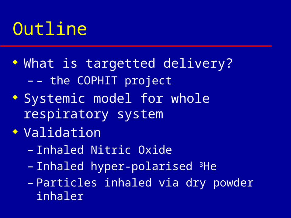
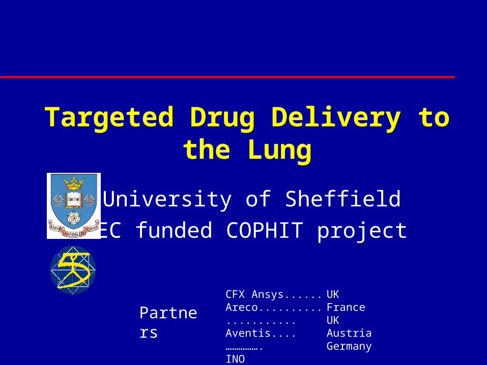
Outline
What is targetted delivery? – – the COPHIT project
Systemic model for whole respiratory system
Validation– Inhaled Nitric Oxide– Inhaled hyper-polarised 3He– Particles inhaled via dry powder inhaler
Inhaled drug delivery - I
Obvious: lung diseases – Asthma– COPD– Cystic Fibrosis– Pulmonary Hypertension
Inhaled drug delivery - II
New not-so-obvious therapies: – Diabetes - Insulin– Pain Management - Morphine– Multiple Sclerosis - Interferon Beta 1a– Osteoporosis - Parathyroid hormone– Infectious Disease - Antibiotics
Lots of advantages but ...
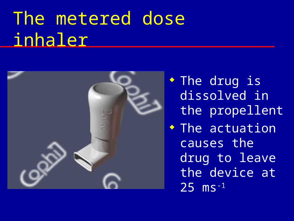
The metered dose inhaler
The drug is dissolved in the propellent
The actuation causes the drug to leave the device at 25 ms-1
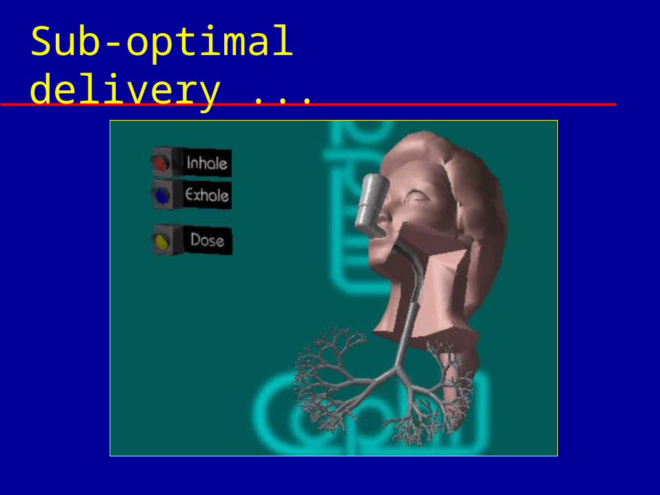
Sub-optimal delivery ...
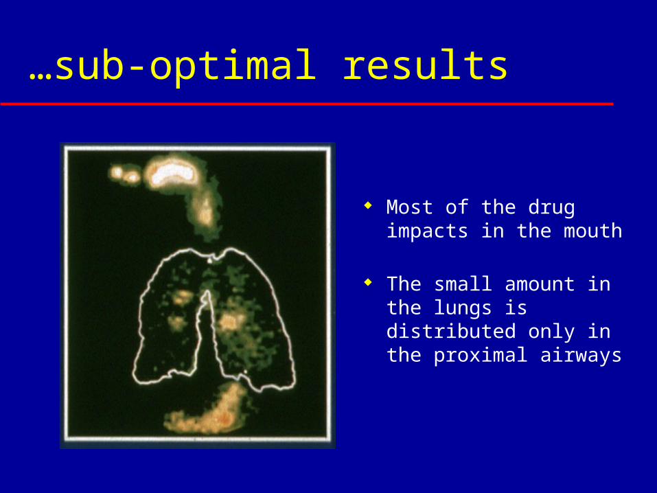
…sub-optimal results
Most of the drug impacts in the mouth
The small amount in the lungs is distributed only in the proximal airways
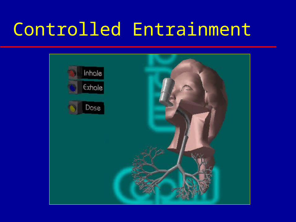
Controlled Entrainment
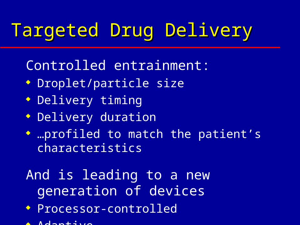
Targeted Drug DeliveryTargeted Drug Delivery
Controlled entrainment: Droplet/particle size Delivery timing Delivery duration …profiled to match the patient’s
characteristics
And is leading to a new generation of devices
Processor-controlled Adaptive
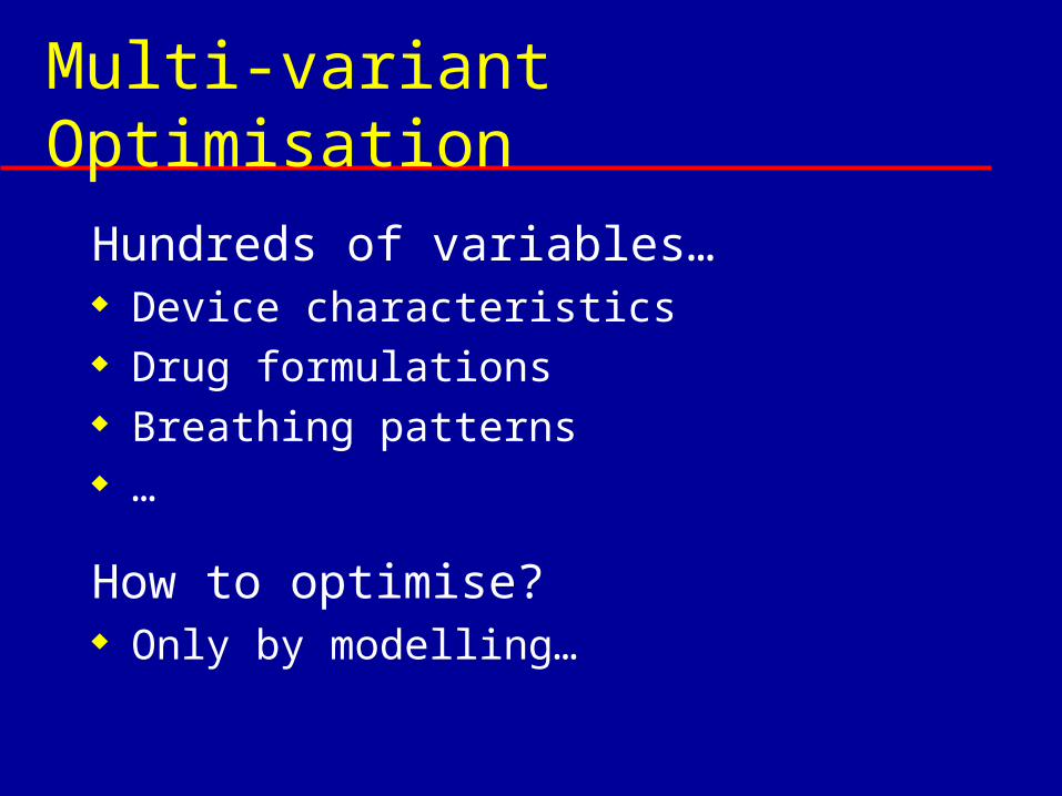
Multi-variant Optimisation
Hundreds of variables… Device characteristics Drug formulations Breathing patterns …
How to optimise? Only by modelling…
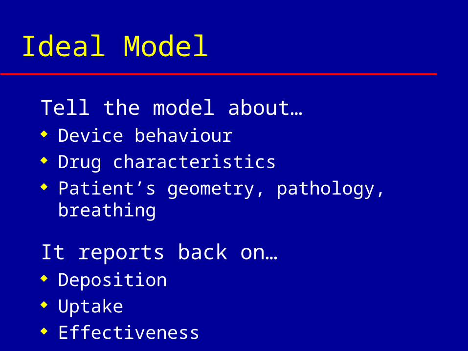
Ideal Model
Tell the model about… Device behaviour Drug characteristics Patient’s geometry, pathology, breathing
It reports back on… Deposition Uptake Effectiveness

COPHIT:
Project AIM
To develop a comprehensive dynamic compartmental model that can track the
progress of inhaled drug delivered from the device through the respiratory system and into
the circulation….
…validated in man by MR-imaging with hyper-polarised 3-He, and other techniques
Computer-Optimised Pulmonary Deliveryin Humans of Inhaled Therapies
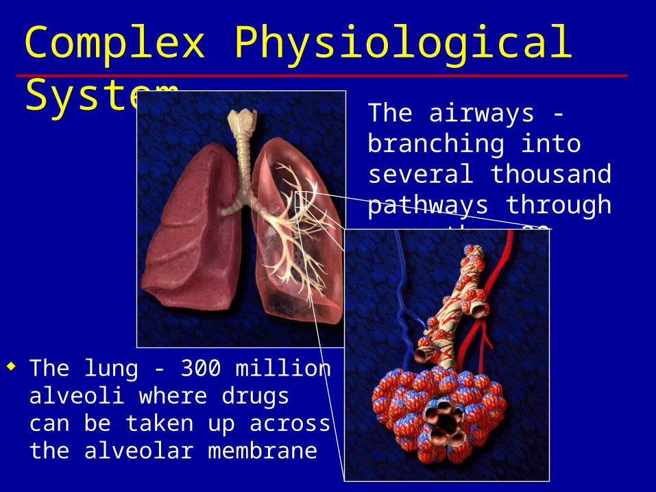
Complex Physiological System The airways -
branching into several thousand pathways through more than 20 bifurcations
The lung - 300 million alveoli where drugs can be taken up across the alveolar membrane
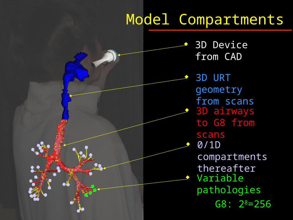
3D Device from CAD
Model Compartments
3D airways to G8 from scans
0/1D compartments thereafter
Variable pathologies
G8: 28=256
3D URT geometry from scans
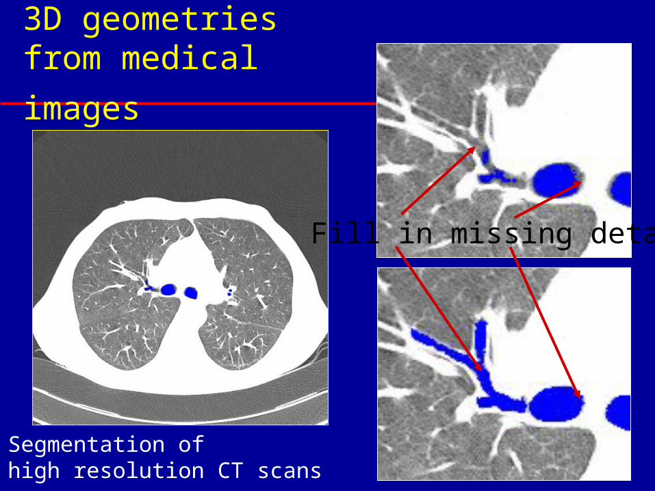
3D geometries from
medical images
Fill in missing detail
Segmentation ofhigh resolution CT scans
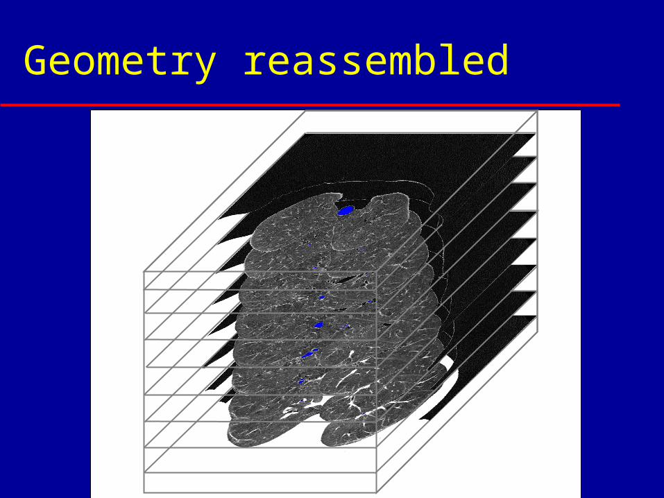
Geometry reassembled
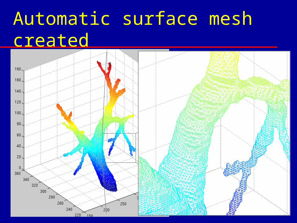
Automatic surface mesh created
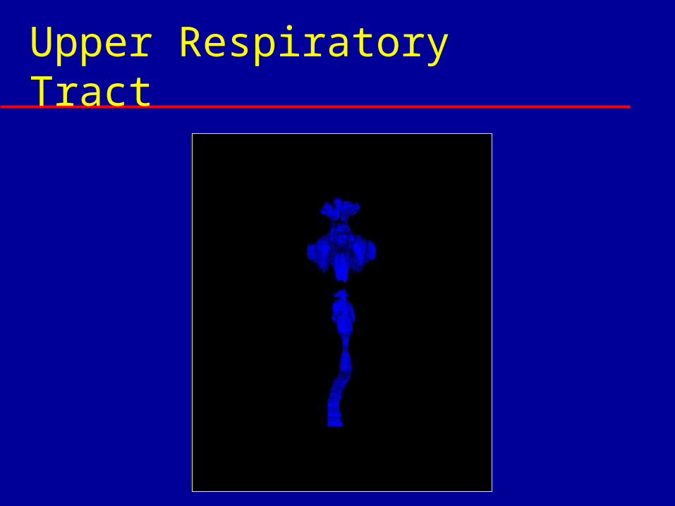
Upper Respiratory Tract
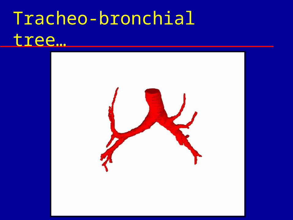
Tracheo-bronchial tree…
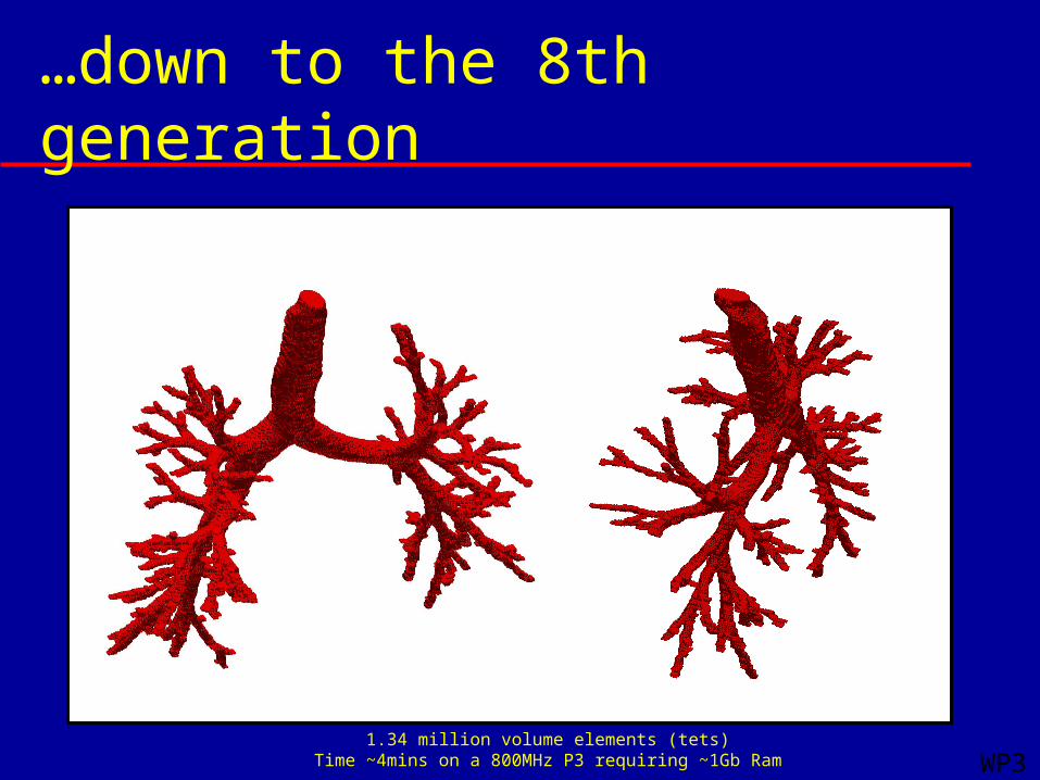
…down to the 8th generation
1.34 million volume elements (tets)Time ~4mins on a 800MHz P3 requiring ~1Gb Ram WP3
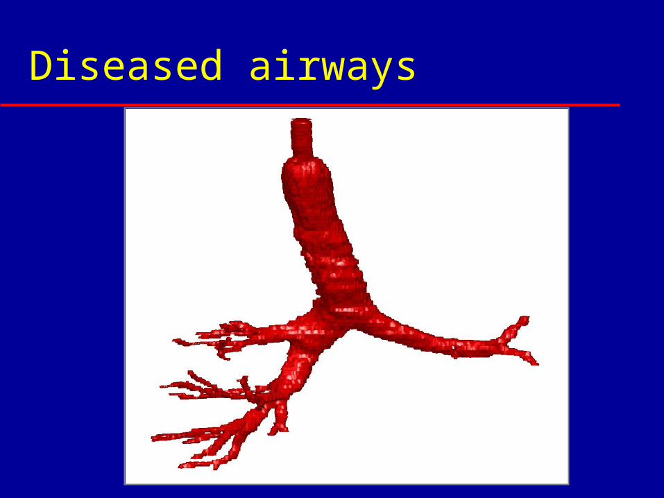
Diseased airways
Flow and Deposition Analysis Full Navier-Stokes equations solved in
3D geometry Subject to certain boundary conditions
Commercially-available CFD software package from partner– CFX 5.6 from CFX Ansys – Extra facilities for aerosol modelling
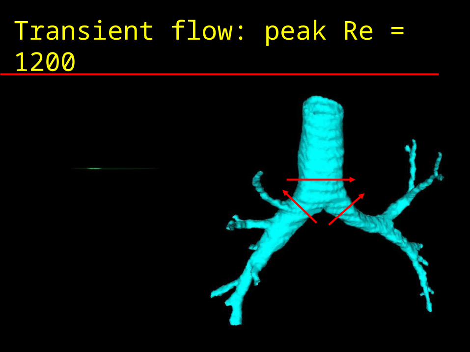
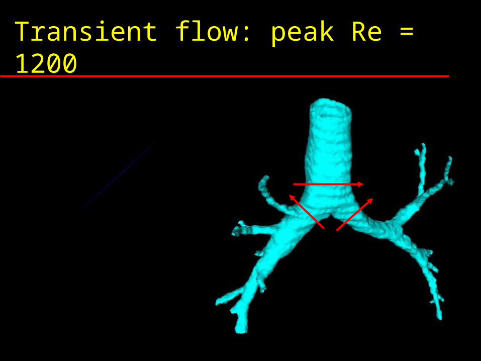
Transient flow: peak Re = 1200
t
V

Transient flow: peak Re = 1200
t
V
Transient flow: peak Re = 1200
t
V
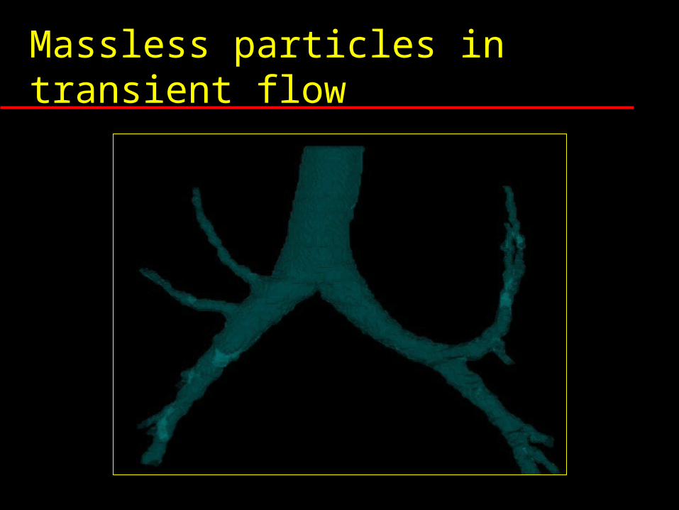
Massless particles in transient flow
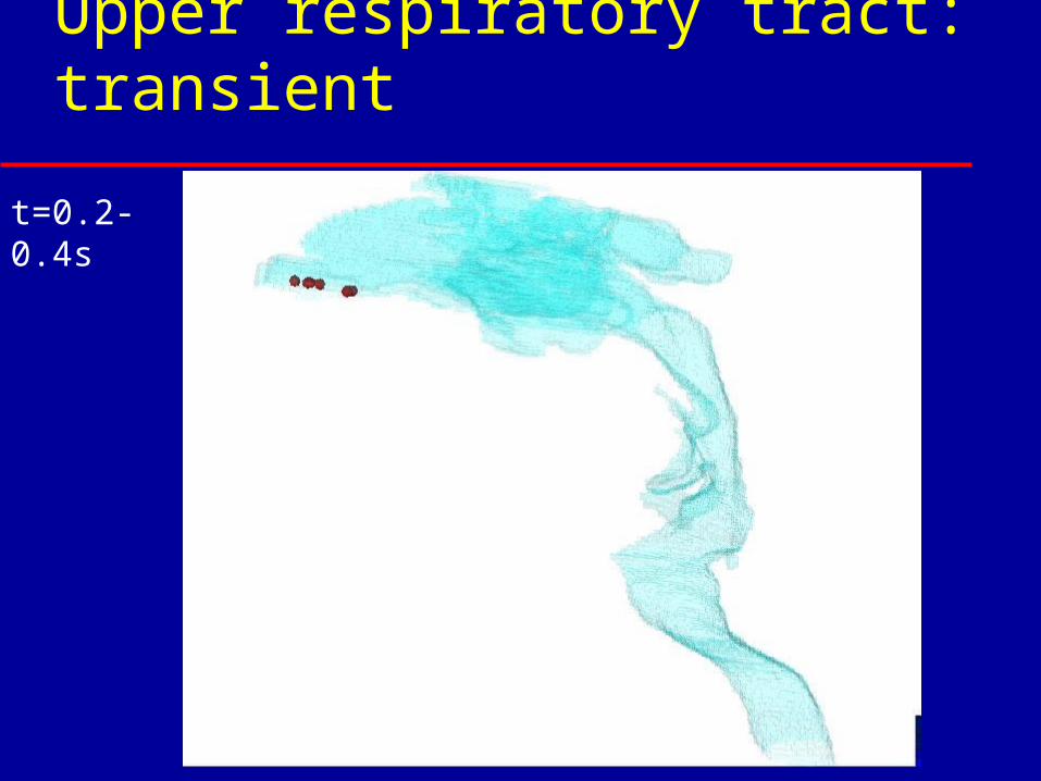
t=0.2-0.4s
Upper respiratory tract: transient
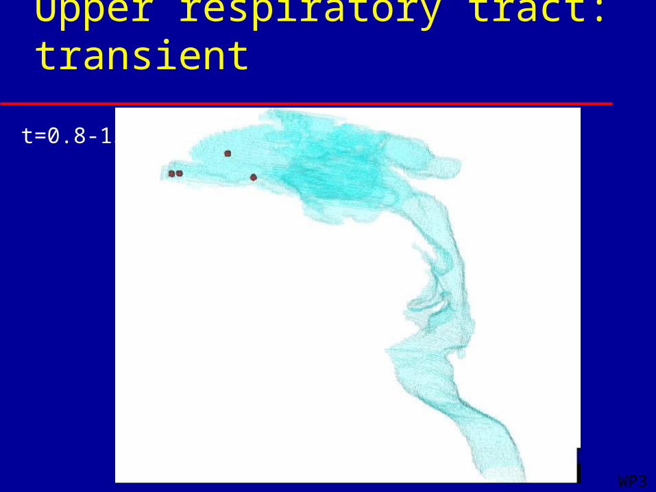
t=0.8-1s
WP3
Upper respiratory tract: transient
Validation
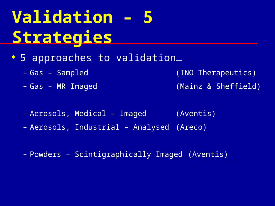
Validation – 5 Strategies 5 approaches to validation…
– Gas – Sampled (INO Therapeutics)
– Gas – MR Imaged (Mainz & Sheffield)
– Aerosols, Medical – Imaged (Aventis)
– Aerosols, Industrial – Analysed (Areco)
– Powders – Scintigraphically Imaged (Aventis)
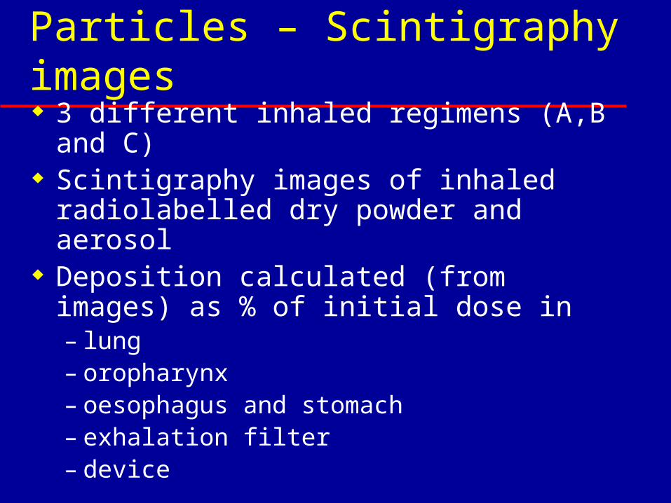
Particles – Scintigraphy images 3 different inhaled regimens (A,B and
C) Scintigraphy images of inhaled
radiolabelled dry powder and aerosol Deposition calculated (from images)
as % of initial dose in – lung – oropharynx – oesophagus and stomach– exhalation filter– device
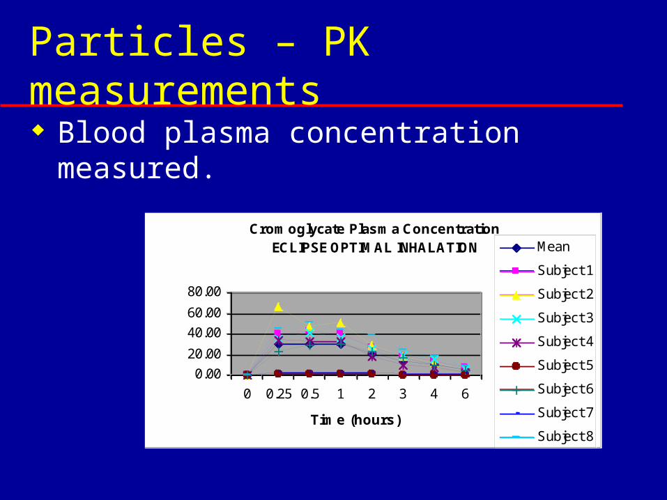
Particles – PK measurements Blood plasma concentration
measured.
Cromoglycate Plasma Concentration ECLIPSE OPTIMAL INHALATION
0.00
20.00
40.00
60.00
80.00
0 0.25 0.5 1 2 3 4 6
Time (hours)
ng/ml
Mean
Subject 1
Subject 2
Subject 3
Subject 4
Subject 5
Subject 6
Subject 7
Subject 8
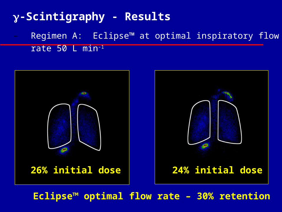
-Scintigraphy - Results
– Regimen A: Eclipse™ at optimal inspiratory flow rate 50 L min-1
Eclipse™ optimal flow rate – 30% retention
24% initial dose26% initial dose
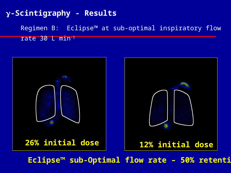
-Scintigraphy - Results
– Regimen B: Eclipse™ at sub-optimal inspiratory flow rate 30 L
min-1
Eclipse™ sub-Optimal flow rate – 50% retention
12% initial dose26% initial dose
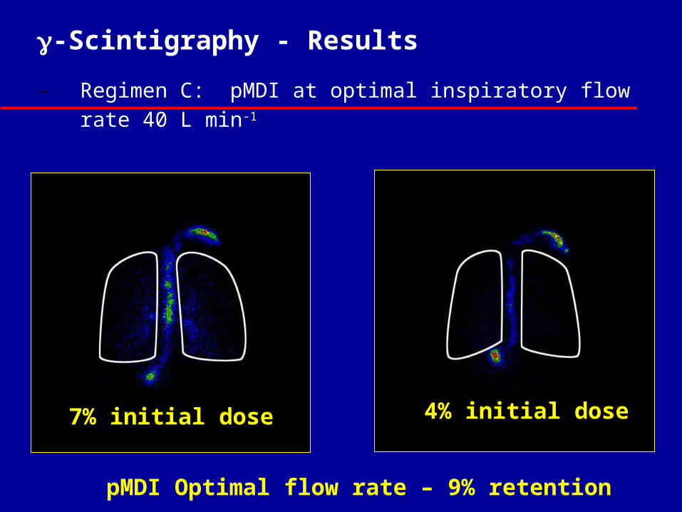
-Scintigraphy - Results
– Regimen C: pMDI at optimal inspiratory flow rate 40 L min-1
pMDI Optimal flow rate – 9% retention
4% initial dose7% initial dose
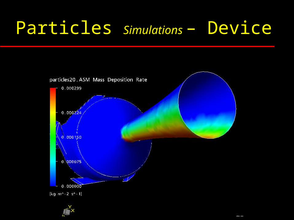
Particles Simulations – Device
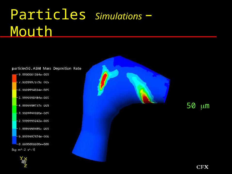
Particles Simulations – Mouth
0.5 m
3 m
7 m
20 m
50 m
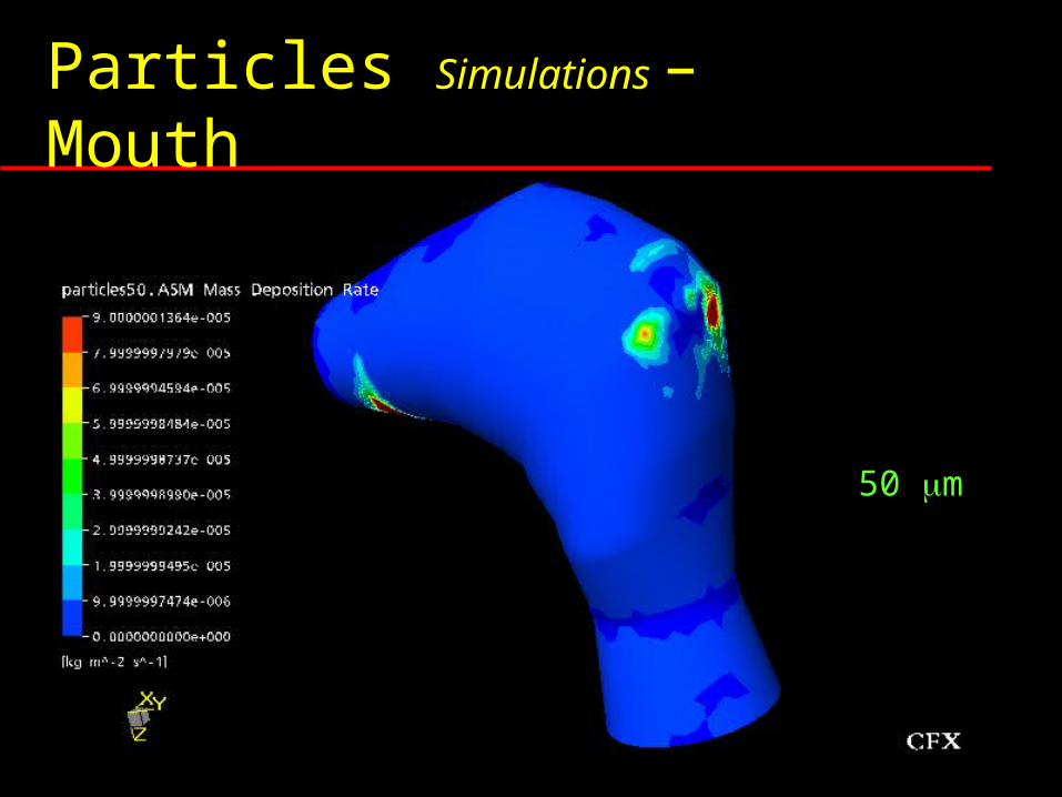
Particles Simulations – Mouth
0.5 m
3 m
7 m
20 m
50 m
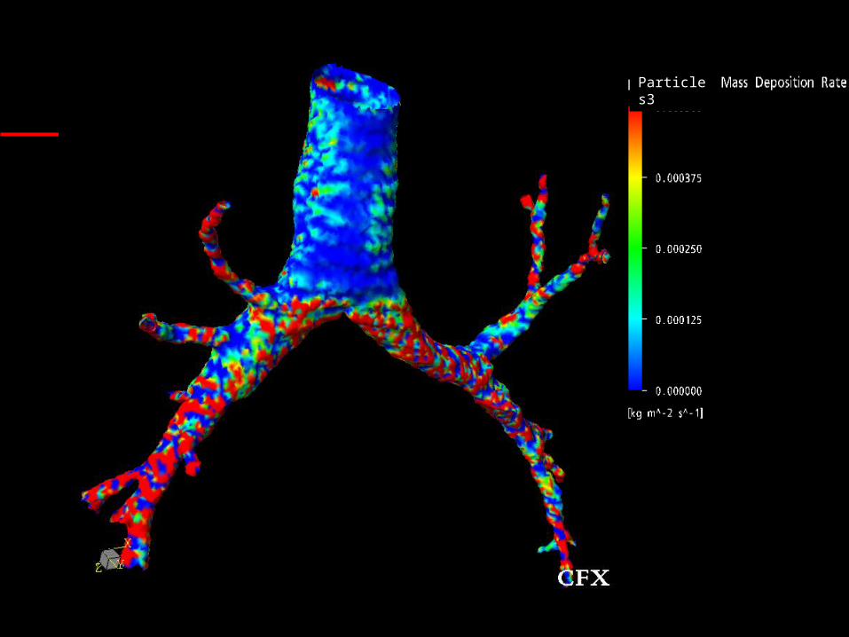
Particles3
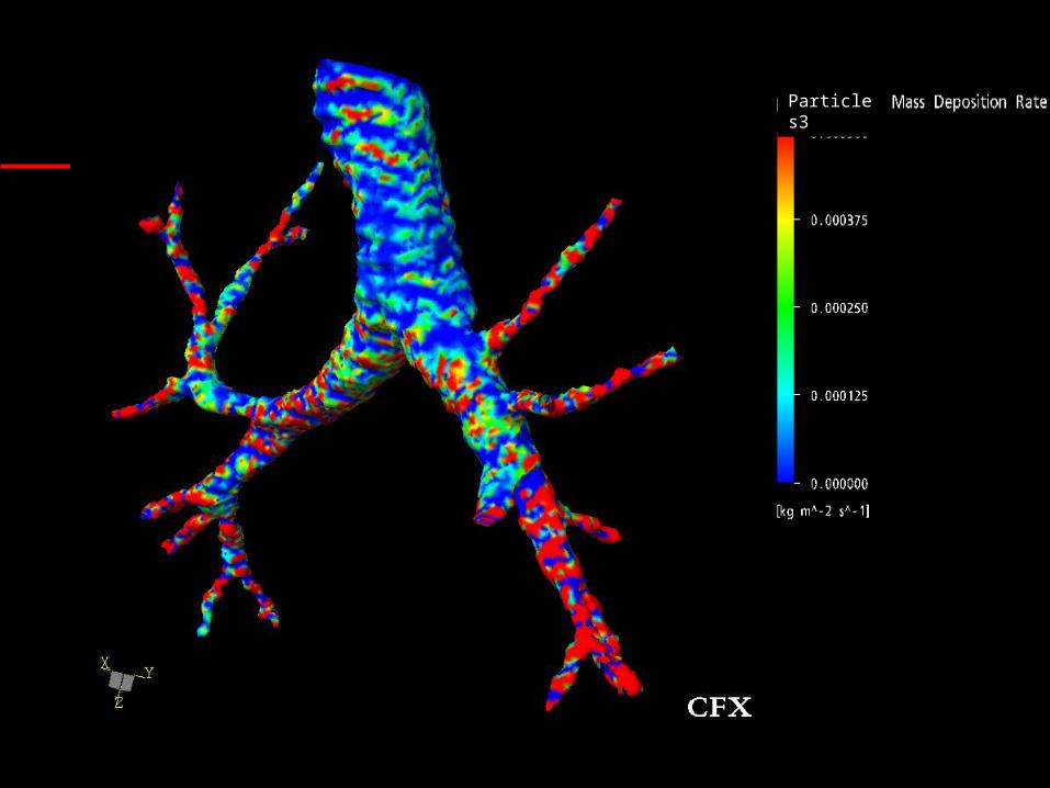
Particles3
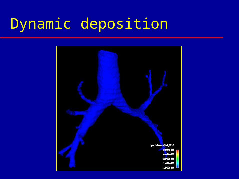
Dynamic deposition
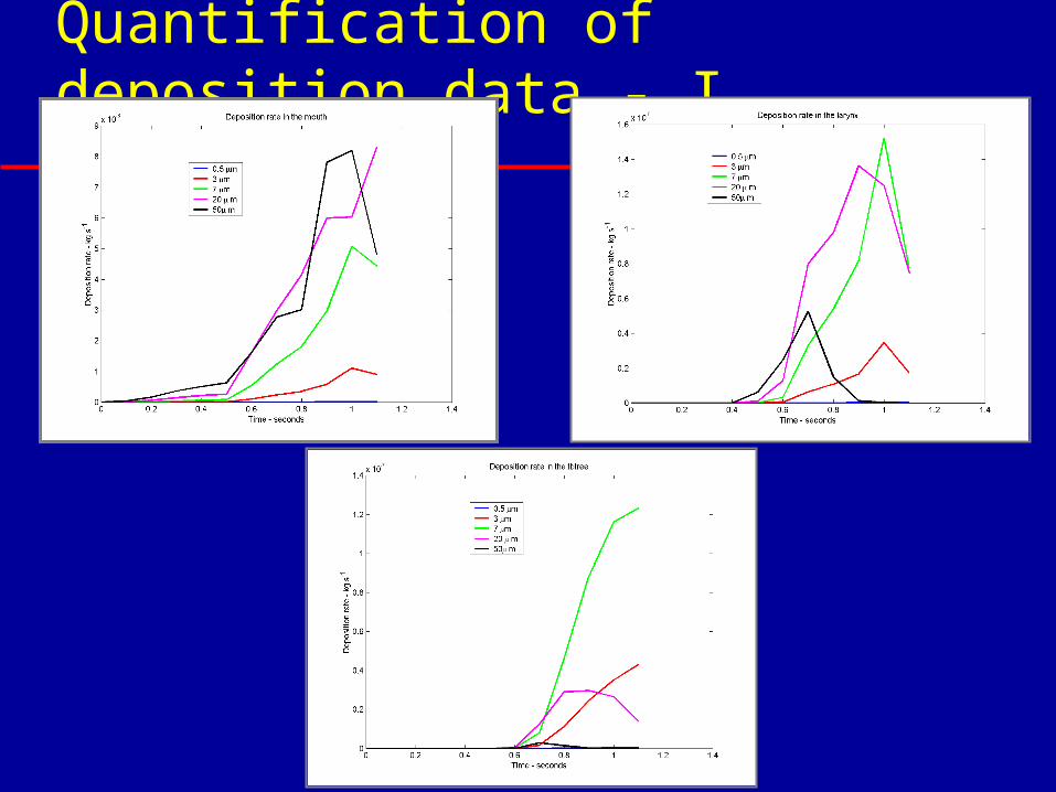
Quantification of deposition data - I
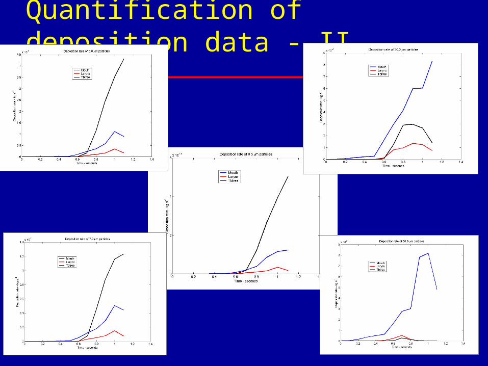
Quantification of deposition data - II
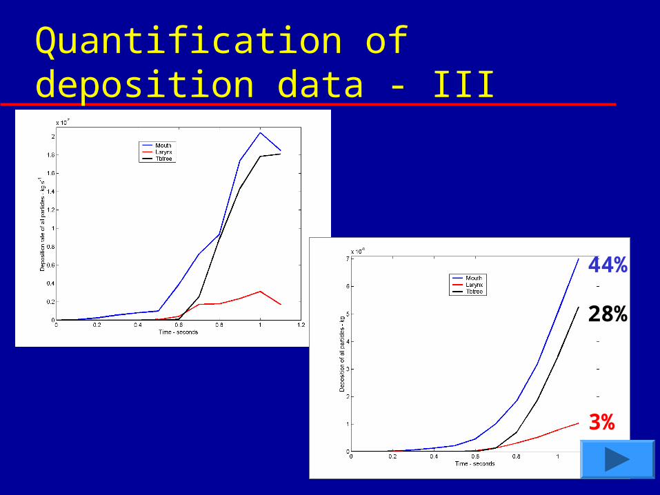
Quantification of deposition data - III
44%
28%
3%
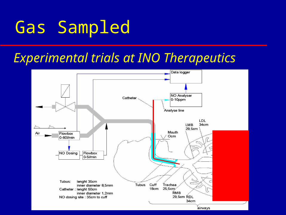
Gas Sampled
Artificially ventilated patients
Experimental trials at INO Therapeutics
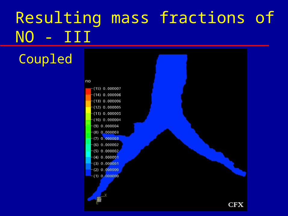
Resulting mass fractions of NO - IIICoupled
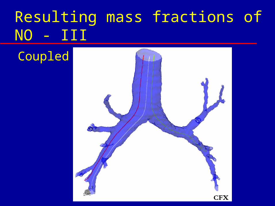
Resulting mass fractions of NO - IIICoupled
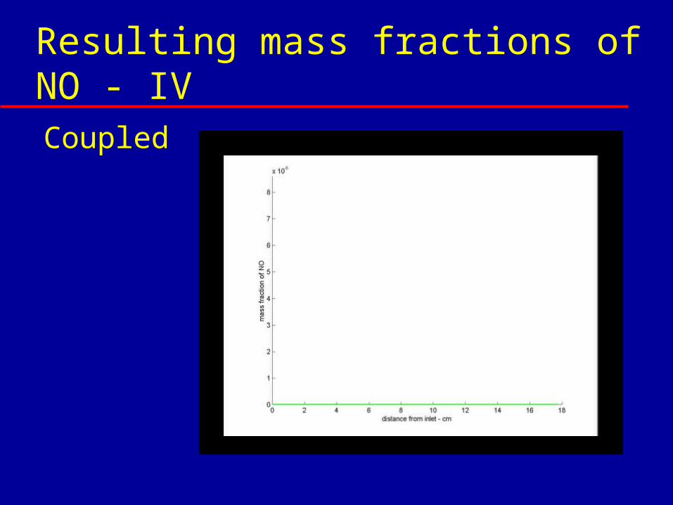
Resulting mass fractions of NO - IVCoupled
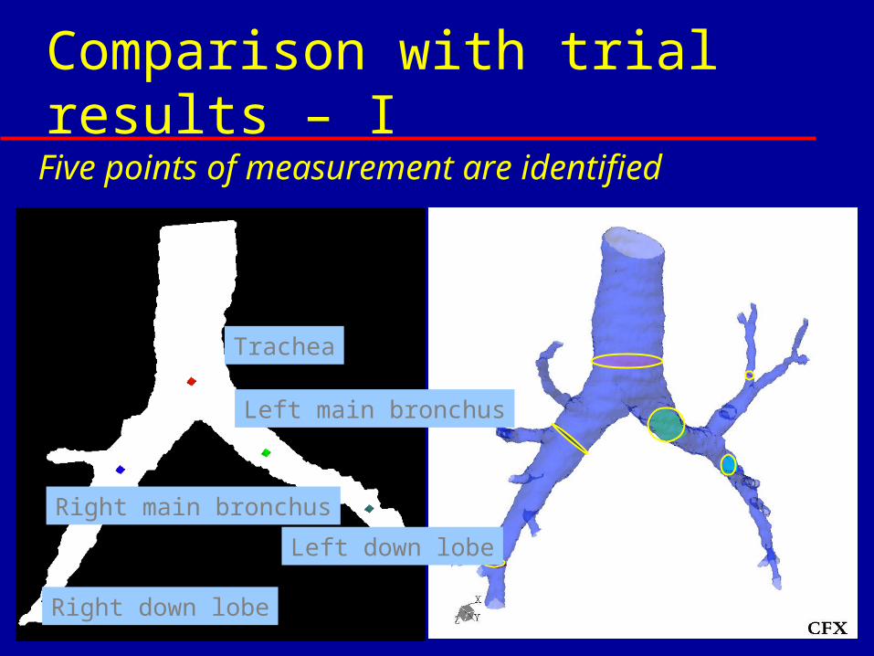
Comparison with trial results – I Five points of measurement are identified
Trachea
Right main bronchus
Left main bronchus
Right down lobe
Left down lobe
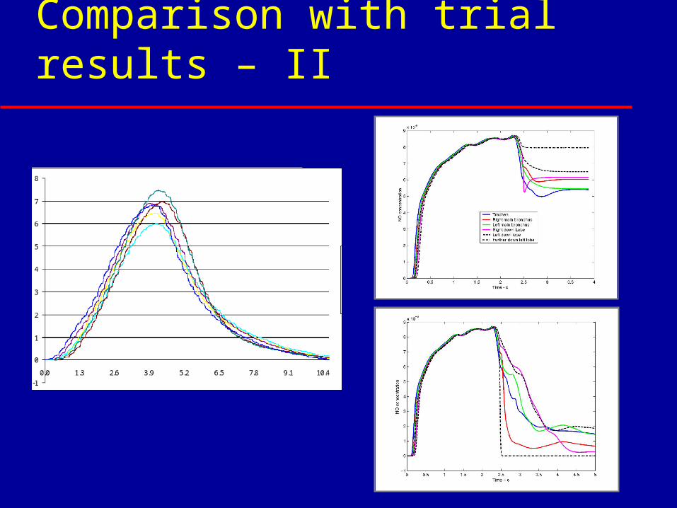
Comparison with trial results – II
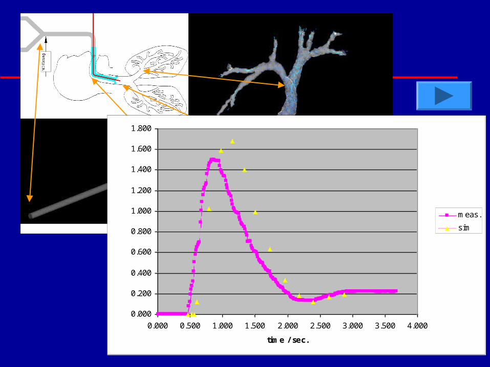
0.000
0.200
0.400
0.600
0.800
1.000
1.200
1.400
1.600
1.800
0.000 0.500 1.000 1.500 2.000 2.500 3.000 3.500 4.000
time / sec.
NO conc. / ppm
meas.
sim
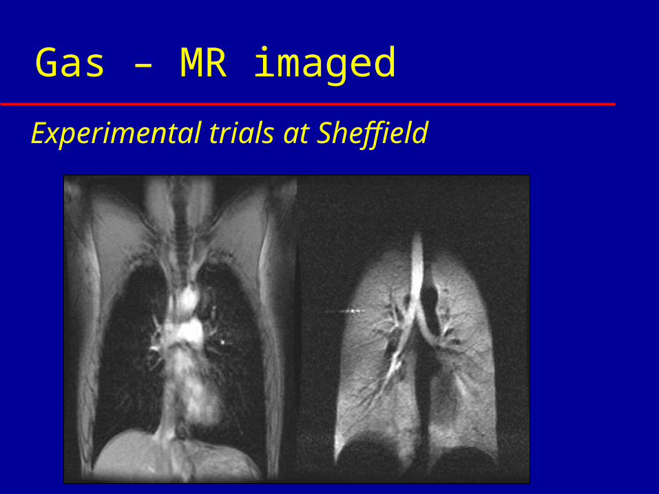
Gas – MR imaged
Experimental trials at Sheffield
Gas – MR imaged
maximum temporal resolution =5.4 ms 1L of 3He and Nitrogen breathed
spontaneously from a bag gas composition = 300cm3 3He, 700cm3 N2
Experimental trials at Sheffield
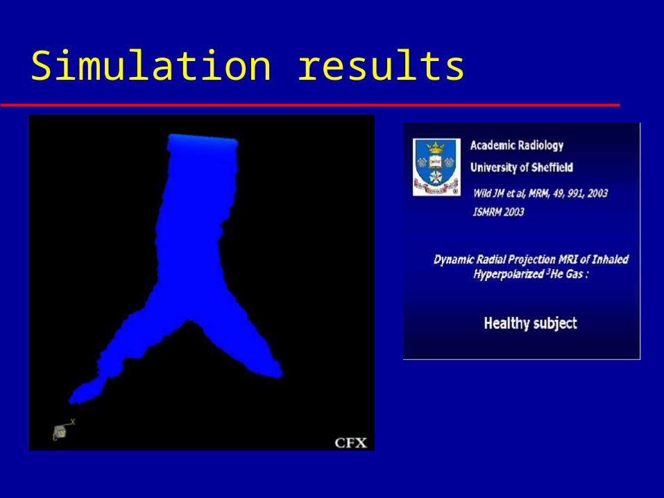
Simulation results
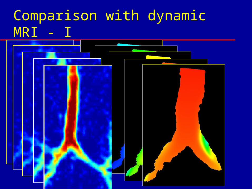
Comparison with dynamic MRI - I
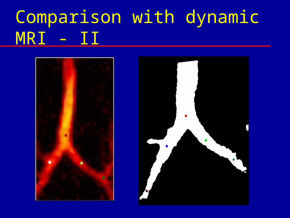
Comparison with dynamic MRI - II
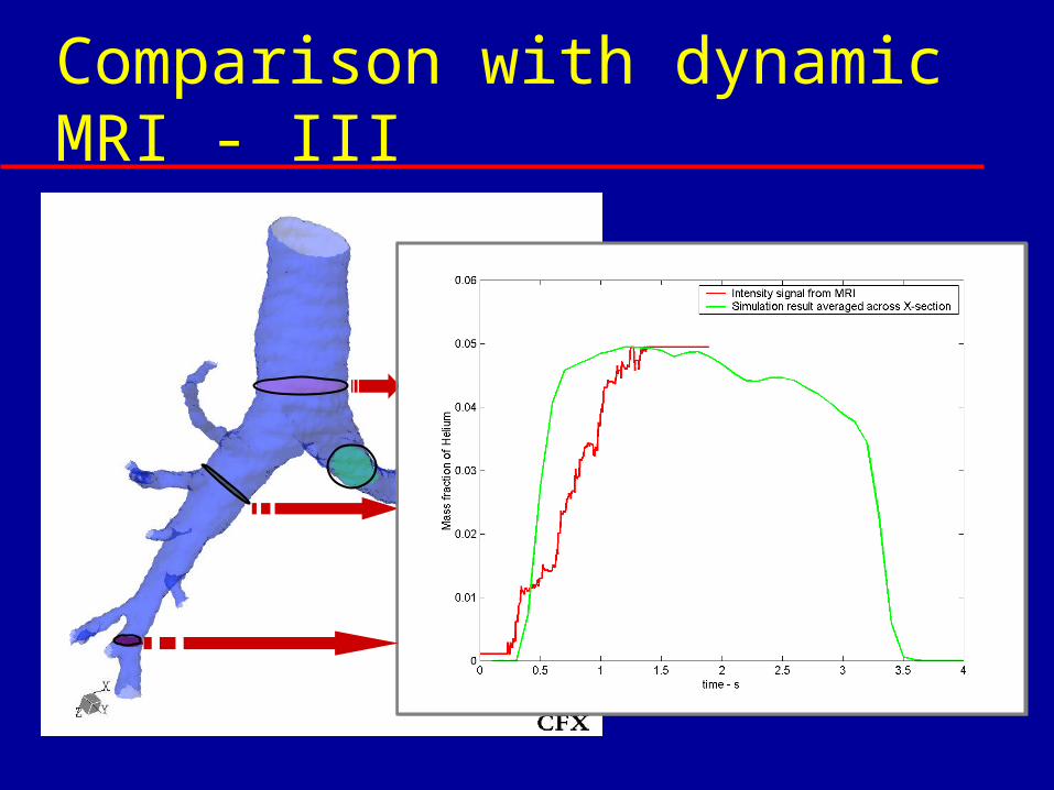
Comparison with dynamic MRI - III
Software - processes
CFX
3-D fluids &
deposition solver
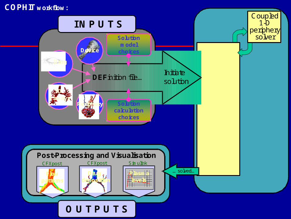
Coupled1-D
peripherysolver
Device
3DAirways
Solutioncalculation
choices
Solutionmodel
choices
Drug
DEFinition file…Initiatesolution
I N P U T S
Post-Processing and VisualisationCFXpostCFXpost
Flowpatterns
Drugdeposition
Simulink
O U T P U T S
Periphery
COPHIT workflow:
F l u i d s s o l v e r
Plasmalevels
…solved…
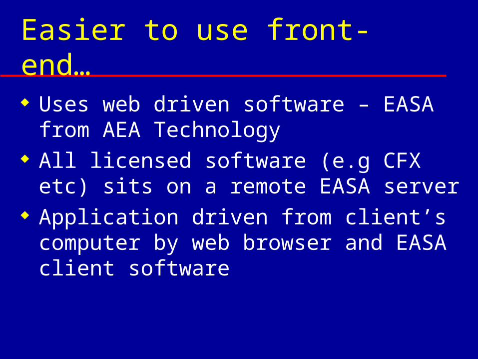
Easier to use front-end…
Uses web driven software – EASA from AEA Technology
All licensed software (e.g CFX etc) sits on a remote EASA server
Application driven from client’s computer by web browser and EASA client software
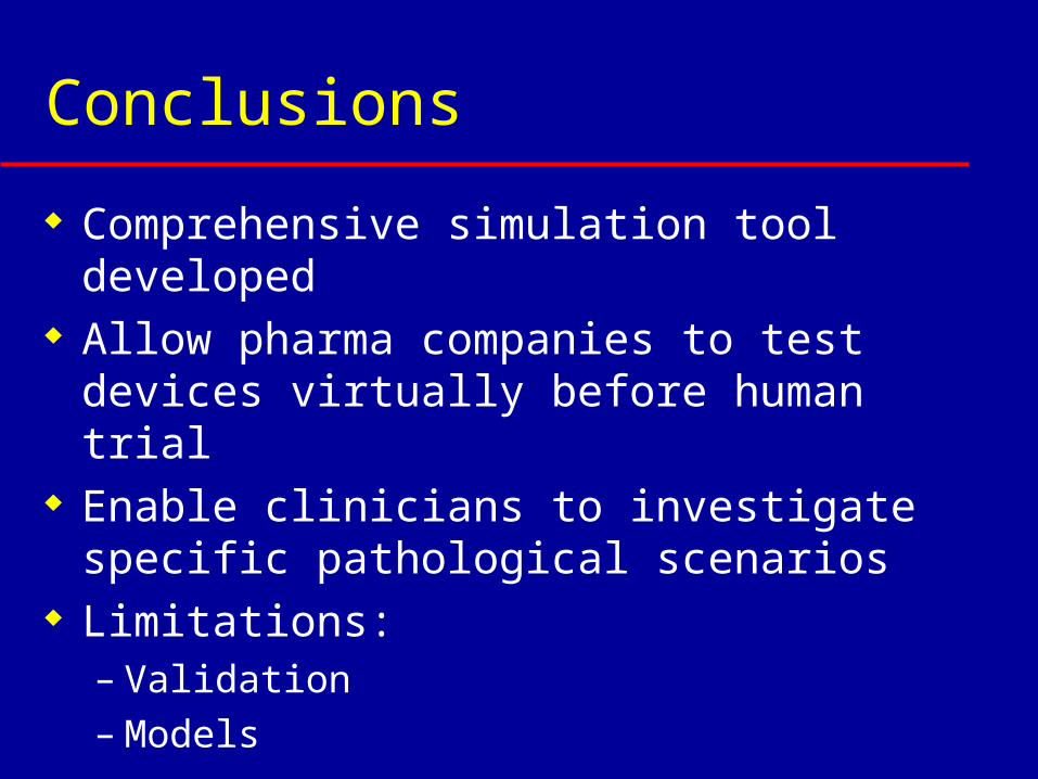
Conclusions
Comprehensive simulation tool developed
Allow pharma companies to test devices virtually before human trial
Enable clinicians to investigate specific pathological scenarios
Limitations:– Validation– Models