Embed Size (px)
Citation preview

GW 10 682 GW 12 682 GW 14 682
Tasca TransponderTransponder slot readerPorte-TransponderBolsillo TransponderTransponder Kartenschlitz

2
Attenzione ! La sicurezza dell'apparecchio è garantita solo attenendosi alle istruzioni qui
riportate. Pertanto è necessario leggerle e conservarle.
I prodotti Chorus devono essere installati conformemente a quanto previsto dalla norma CEI
64-8 per gli apparecchi per uso domestico e similare, in ambienti non polverosi ed ove non
sia necessaria una protezione speciale contro la penetrazione di acqua.
L'organizzazione di vendita GEWISS é a disposizione per chiarimenti e informazioni
tecniche.
Gewiss SpA si riserva il diritto di apportare modifiche al prodotto descritto in questo manuale
in qualsiasi momento e senza alcun preavviso.
Attenzione - Importante

INDICE
3
ITALIANO
ISTRUZIONI D’IMPIEGO pag.
- Descrizione del prodotto e suo funzionamento ........................................................ 4
- Vista frontale ........................................................................................................... 5
INSTALLAZIONE
- Collegamenti ........................................................................................................... 6
- Posizione indicatori ed elementi di comando ........................................................... 7
- Avvertenze per l'installazione .................................................................................. 8
- Montaggio e collegamento ...................................................................................... 8
- Descrizione generale ............................................................................................... 9
- Collegamento del cavo bus al morsetto KNX / EIB ................................................... 9
- Collegamento del lettore di transponder alla linea bus ........................................... 9
- Sicurezza elettrica................................................................................................... 9
- Condizioni di impiego .............................................................................................. 10
- Omologazione ........................................................................................................ 10
- Marcatura CE .......................................................................................................... 10
CARATTERISTICHE TECNICHE ........................................................................................... 11

ISTRUZIONI D’IMPIEGO
4
Descrizione del prodotto e suo funzionamentoLa tasca porta transponder GW1X 682 è un dispositivo KNX / EIB che permette ilriconoscimento delle tessere transponder e la notifica delle presenze di supervisione (es.reception);
L’apparecchio è dotato di tre ingressi fisici ON/OFF disponibili per il controllo dello switchdi porta aperta/chiusa o di altri segnali (contatto finestra, tirante allarme bagno ecc. ecc).Sul dispositivo sono presenti due relè 24Vac, da utilizzare ad esempio per il controllo dellaserratura della porta, per il comando della “luce di cortesia”, per abilitazione carichi elettricipresenti nell’ambiente o per altro uso.
La lettura del transponder avviene inserendo la tessera nell’apposita tasca frontale.
La configurazione dell’apparecchio, indirizzo fisico, parametri e oggetti di comunicazione,avviene mediante il software ETS (Eib Tool Software). Il database del prodotto è liberamentescaribabile dal sito www.gewiss.com, (area prodotti – Domotics)
La tasca porta transponder viene posizionata all’interno di scatole da incasso o paretestandard, ed installata nei supporti della serie Chorus nello spazio di tre moduli.

ISTRUZIONI D’IMPIEGO
5
ITALIANO
Vista frontale
Tasca illuminata per l’inserimento delle tessere transponder
In assenza della tessera, la retroilluminazione ON / OFF della tasca portabadge è unparametro liberamente configurabile da ETS; a tessera inserita la retroilluminazione è sempre OFF.
INSTALLAZIONE
6
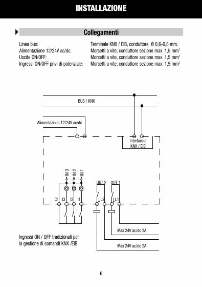
Linea bus: Terminale KNX / EIB, conduttore Ø 0,6-0,8 mm.Alimentazione 12/24V ac/dc: Morsetti a vite, conduttore sezione max. 1,5 mm2
Uscite ON/OFF: Morsetti a vite, conduttore sezione max. 1,5 mm2
Ingressi ON/OFF privi di potenziale: Morsetti a vite, conduttore sezione max. 1,5 mm2
Collegamenti
BUS / KNX
Interfaccia KNX / EIB
OUT 2 OUT 1
Max 24V ac/dc 2A
Max 24V ac/dc 2A
IN 3
IN 2
IN 1
CI I3 I2 I1 L2 L1
Alimentazione 12/24V ac/dc
Ingressi ON / OFF tradizionali per la gestione di comandi KNX /EIB
INSTALLAZIONE
7
ITALIANO
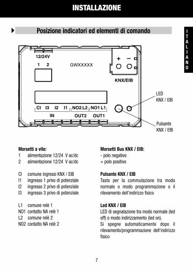
Morsetti a vite:1 alimentazione 12/24 V ac/dc2 alimentazione 12/24 V ac/dc
CI comune ingressi KNX / EIB I1 ingresso 1 privo di potenzialeI2 ingresso 2 privo di potenzialeI3 ingresso 3 privo di potenziale
L1 comune relè 1NO1 contatto NA relè 1L2 comune relè 2NO2 contatto NA relè 2
Morsetti Bus KNX / EIB:- polo negativo + polo positivo
Pulsante KNX / EIBTasto per la commutazione tra modonormale o modo programmazione o ilrilevamento dell’indirizzo fisico
Led KNX / EIBLED di segnalazione tra modo normale (ledoff) o modo indirizzamento (led on). Si spegne automaticamente dopo ilrilevamento/programmazione dell’indirizzofisico
Posizione indicatori ed elementi di comando
LED KNX / EIB
Pulsante KNX / EIB
KNX/EIB
1 2
12/24V
CI I3 I2 I1
IN OUT2 OUT1
GWXXXXX
NO2 L2 NO1 L1
+ –

INSTALLAZIONE
8
L’apparecchio deve essere impiegato per installazione fissa in ambienti chiusi, spaziasciutti, in scatole da incasso o parete.
• L’apparecchio non può essere installato nella stessa cassetta insieme a dispositivi a 230V. • L’apparecchio deve essere installato e messo in servizio da un installatore abilitato.• Devono essere osservate le norme in vigore in materia di sicurezza e prevenzione
antinfortunistica.• L’apparecchio non deve essere aperto. Eventuali apparecchi difettosi devono essere fatti
pervenire alla sede competente.
Avvertenze per l‘installazione
Montare il lettore esclusivamente in posizione orizzontale.
Montaggio e collegamento
INSTALLAZIONE
9
ITALIANO
Per effettuare la messa in servizio occorre poter accedere al “Pulsante KNX / EIB” per lacommutazione tra modo normale e modo programmazione che si trova sul lato posterioredella custodia. In fase di installazione prevedere lunghezze di collegamento dei cavi che permettanol’estrazione dell’insieme apparecchio/telaio di montaggio dalla scatola da incasso.
Descrizione generale
Il morsetto Bus KNX / EIB (compreso nella fornitura) è adatto ad un conduttore unifilarecon Ø 0,6-0,8 mm.
Collegamento del cavo bus al morsetto KNX / EIB
Inserire il morsetto Bus KNX / EIB, precedentemente collegato al cavo bus, nella fessuraguida dell’accoppiatore bus integrato che si trova sul lato posteriore del dispositivo. Far scorrere il morsetto bus fino all’arresto.
Collegamento del lettore di transponder alla linea bus
Il lettore di transponder deve essere configurato tramite uno dei software di gestioneaccessi "GWHotel" o "GWAccess" per la configurazione delle tessere transponder el'assegnazione dei diritti di accesso
Configurazione

INSTALLAZIONE
10
Rispettati EN 61000-6-3, EN 61000-6-1 e EN 50090-2-2
Requisiti EMC
Secondo norma EN 50090-2-2.Temperatura ambiente durante il funzionamento: 0°C + 45°C.Temperatura di stoccaggio: - 20 + 55°C.Umidità relativa: max 90%.
Condizioni di impiego
Omologato KNX/EIB.
Omologazione
Conformemente alla direttiva CE (edilizia abitativa e industriale), direttiva sulla bassatensione.
Marcatura CE
Grado di inquinamento (secondo IEC 60664-1): 2.Grado di protezione (secondo EN 60529): IP 20.Classe di protezione (secondo IEC 61140): III. Classe di sovratensione (secondo IEC 664-1): III.Bus: tensione di sicurezza SELV DC 24V.Soddisfa EN 50090 e IEC 664-1.
Sicurezza elettrica

CARATTERISTICHE TECNICHE
11
ITALIANO
AlimentazioneTensione BUS KNX/EIB: 29V dc SELVAssorbimento dal BUS: 5mATensione ausiliaria esterna: 12/24V ac/dc +/- 10%Assorbimento max da tensione ausiliaria: 150mA
Ingressi KNX / EIB3 contatti privi di potenzialel’alimentazione è fornita dall’interno 24V 1mA
Uscite a relè2 contatti NA 2A cosϕ 0.6, 24V acCanale 1: uso generico o comando elettroserraturaCanale 2: luce di cortesia o uso generico
Lettore di transponderChip lettura/scrittura transponder Atmel/Temic.Alimentazione fornita dall’interno 5V dcFrequenza di lavoro 125KHz
Elementi di comandoTasto per commutazione modo normale/modo programmazione
IndicatoriTasca porta badge illuminata


Transponder slot reader
E N G L I S H

14
Warning! The safety of this appliance is only guaranteed if all the instructions given here
are followed scrupulously. These should be read thoroughly and kept in a safe place.
All Chorus products must be installed in compliance to CEI 64-8 Standards for household
appliances and similar items, in dust-free environments where no special protection is
required to prevent penetration of water.
The GEWISS sales organisation is at your disposal for clarifications and technical
information.
Gewiss SpA reserves the right to make changes to the product described in this manual at
any time and without giving any notice.
Attention - Important

CONTENTS
15
OPERATING INSTRUCTIONS page
- Description of the product and how it works .......................................................16
- Front view ...........................................................................................................17
INSTALLATION
- Connections ........................................................................................................18
- Indicators and control elements positions............................................................19
- Warnings for installation phase............................................................................20
- Assembly and connections ..................................................................................20
- General description .............................................................................................21
- Connection of the bus cable to the KNX/EIB terminal...........................................21
- Connection of the transponder reader to the bus line ..........................................21
- Electrical safety ...................................................................................................21
- Conditions of use.................................................................................................22
- Homologation .....................................................................................................22
- EC Marking..........................................................................................................22
TECHNICAL SPECIFICATIONS .......................................................................................23
ENGLISH

OPERATING INSTRUCTIONS
16
Description of the product and how it worksThe transponder slot reader GW1X 682 is a KNX / EIB device which allows the transponderto recognise the badges and notify the presence of supervision (e.g. reception);
The device is fitted with three physical ON/OFF inputs to control the door open/closedswitch or other signals (window contact, bathroom alarm etc ).The device has two 24Vac relays which are used, for instance, to control the lock on doors,to control "courtesy lights" to enable electrical loads present in the environment or other.
The transponder reading is performed by inserting the badge into the front slot reader.
The configuration of the device, the physical address, parameters and communicationobjects are all performed using the ETS software (Eib Tool Software). The product databasecan be downloaded from our website at www.gewiss.com, (product area - Domotics)
The transponder slot reader is placed inside a standard flush-mounted box, and mountedon Chorus supports in the space of three modules.

OPERATING INSTRUCTIONS
17
ENGLISH
Front view
Backlit slot reader to insert the transponder badges
If there is no badge, the ON / OFF backlight setting on the badge slot reader can beconfigured using the ETS software; when a badge is inserted the backlight is always OFF.

INSTALLATION
18
Bus Line: KNX / EIB terminal, conductor Ø 0.6-0.8 mm.12/24V ac/dc power supply: Screw terminals, max cable section 1.5 mm2
ON/OFF outputs: Screw terminals, max cable section 1.5 mm2
ON/OFF inputs without potential: Screw terminals, max cable section 1.5 mm2
Connections
BUS / KNX
InterfaceKNX / EIB
OUT 2 OUT 1
Max 24V ac/dc 2A
Max 24V ac/dc 2A
IN 3
IN 2
IN 1
CI I3 I2 I1 L2 L1
Power supply 12/24V ac/dc
Traditional ON / OFF inputs tomanage the KNX / EIB commands
INSTALLATION
19
ENGLISH
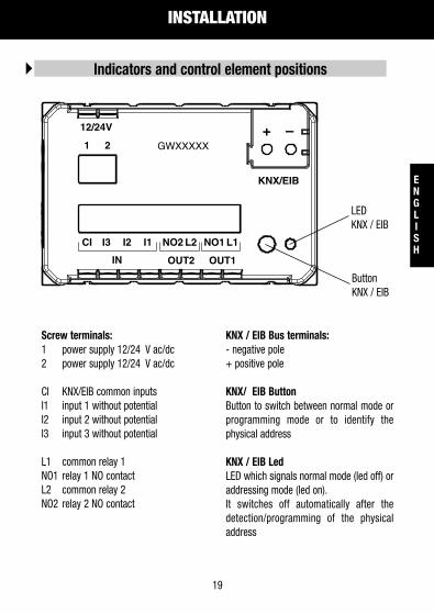
Screw terminals:1 power supply 12/24 V ac/dc2 power supply 12/24 V ac/dc
CI KNX/EIB common inputsI1 input 1 without potentialI2 input 2 without potentialI3 input 3 without potential
L1 common relay 1NO1 relay 1 NO contactL2 common relay 2NO2 relay 2 NO contact
KNX / EIB Bus terminals:- negative pole+ positive pole
KNX/ EIB ButtonButton to switch between normal mode orprogramming mode or to identify thephysical address
KNX / EIB LedLED which signals normal mode (led off) oraddressing mode (led on). It switches off automatically after thedetection/programming of the physicaladdress
Indicators and control element positions
LEDKNX / EIB
ButtonKNX / EIB
KNX/EIB
1 2
12/24V
CI I3 I2 I1
IN OUT2 OUT1
GWXXXXX
NO2 L2 NO1 L1
+ –

INSTALLATION
20
The device must be used for fixed installations in closed environments, dry areas, in wallor flush-mounted boxes.• The device cannot be installed inside the same box together with 230 V devices. • Only qualified personnel are permitted to install and start up the device.• Always comply with the safety and accident prevention standards and regulations in
force.• The device must not be opened. Any faulty devices must be returned to the relative
service center.
Warnings for installation phase
Only mount the reader in a horizontal position.
Assembly and connections

INSTALLATION
21
ENGLISH
To start up the device you must access the "KNX / EIB Button" to switch from normal modeto programming mode; the button is on the back of the casing. When installing the device, make sure that the connection cables are long enough to extractthe device / support frame from the flush-mounted box together.
General description
The Bus KNX / EIB clamp (supplied with the device) is suitable for a single wireconductor with a Ø 0.6-0.8 mm.
Connection of the bus cable to the KNX / EIB clamp
Insert the KNX / EIB Bus clamp, previously connected to the bus cable, into the integratedbus coupling slot which is on the back of the device. Slide the bus clamp as far as possible.
Connection of the transponder reader to the bus line
The transponder reader must be configured using one of the access managementsoftwares - "GWHotel" or "GWAccess" used to configure the transponder badges and theassigning of access rights
Configuration

INSTALLATION
22
Complies with EN 61000-6-3, EN 61000-6-1 and EN 50090-2-2 Standards.
EMC requirements
According to EN 50090-2-2 Standards.Ambient temperature while working: 0°C +45°C.Storage temperature: - 20 + 55°C.Relative humidity: max. 90%.
Conditions of use
KNX/EIB homologated.
Homologation
Complies to the low voltage EC Directive (civil and industrial building).
EC Marking
Pollution level (according to IEC 60664-1 Standard): 2.Protection rating (according to EN 60529 Standard): IP 20.Protection class (according to IEC 61140): III.Overload rating (according to IEC 664-1): III.Bus: safety voltage SELV DC 24V.Complies with EN 50090 and IEC 664-1 Standards.
Electrical safety

TECHNICAL SPECIFICATIONS
23
ENGLISH
Power supplyBUS voltage KNX/EIB: 29V dc SELVBUS absorption: 5mAExternal auxiliary voltage: 12/24V ac/dc +/- 10%Max. auxiliary power absorption: 150mA
KNX/EIB Inputs3 contacts without potentialthe power is supplied internally at 24V 1mA
Relay outputs2 NO contacts 2A cosϕ 0,6, 24V acChannel 1: general use or electrical lock commandChannel 2: courtesy lights or general use
Transponder readerChip reader/writer transponder Atmel/TemicPower supplied internally at 5V dcWorking power frequency: 125KHz
Control elementsButton to switch between normal mode / programming mode
IndicatorsBacklit badge slot reader


Porte-Transponder
F R A N Ç A I S

26
Attention ! La sécurité de l'appareil n'est garantie que si les instructions ici indiquées sont
respectées. Il est donc nécessaire de bien les lire et les conserver.
Les produits de la gamme Chorus doivent être installés conformément aux dispositions de
la norme CEI 64-8 pour les appareils à usage ménager et similaires, dans des
environnements non poussiéreux et là où il n’est pas nécessaire de mettre en place une
protection spéciale contre la pénétration de l’eau.
L’organisation de vente de la Société GEWISS est à votre disposition pour tous
éclaircissements et toutes informations techniques.
Gewiss SpA se réserve le droit de faire des modifications sur le produit décrit dans ce manuel
à n’importe quel moment et sans aucun préavis.
Attention - Important

FRANÇAIS
SOMMAIRE
27
FRANÇAIS
INSTRUCTIONS D'UTILISATION page
- Description du produit et de son fonctionnement ............................................. 28
- Vue frontale...................................................................................................... 29
INSTALLATION
- Raccordements ................................................................................................ 30
- Position des indicateurs et des éléments de commande .................................. 31
- Avertissements pour l’installation..................................................................... 32
- Montage et connexion...................................................................................... 32
- Description générale ........................................................................................ 33
- Connexion du câble bus à la borne KNX / EIB................................................... 33
- Connexion du lecteur de transponder à la ligne bus ......................................... 33
- Sécurité électrique ........................................................................................... 33
- Conditions d'emploi ......................................................................................... 34
- Homologation .................................................................................................. 34
- Marque CE ....................................................................................................... 34
CARACTÉRISTIQUES TECHNIQUES ............................................................................ 35

INSTRUCTIONS D'UTILISATION
28
Description du produit et de son fonctionnementLe porte-transponder GW1X 682 est un dispositif KNX/EIB qui permet de reconnaître lescartes transponder et de notifier les présences de la supervision (ex. réception) ;
L'appareil est muni de trois entrées physiques MARCHE/ARRET, disponibles pour contrôlerle switch de porte ouverte/fermée, ou bien d'autres signaux (contact fenêtre, tirant d'alarmesalle de bain, etc.).Sur le dispositif se trouvent deux relais 24Vca, à utiliser par exemple pour contrôler laserrure de la porte, pour commander la "lumière de service", pour activer des chargesélectriques présentes dans la pièce, ou pour tout autre emploi.
Pour lire le transponder, il faut insérer la carte dans le porte-transponder frontal prévu.
La configuration de l'appareil, de l'adresse physique, des paramètres et des objets decommunication, se réalise grâce au logiciel ETS (Eib Tool Software). La base de donnéespeut être téléchargée librement du site www.gewiss.com, (section produits - Domotics).
Le porte-transponder est placé à l'intérieur de boîtes encastrables ou par fixation au murstandard, et monté sur des supports de la série Chorus, dans l’espace de trois modules.

FRANÇAIS
INSTRUCTIONS D'UTILISATION
29
FRANÇAIS
Vue frontale
Porte-transponder éclairé pour l'insertion des cartes transponder
Quand il n'y a pas de carte, le rétroéclairage MARCHE/ARRET du porte-carte est unparamètre qui peut être librement configuré à partir du ETS;quand la carte est insérée, le rétroéclairage est toujours à l'ARRET.

INSTALLATION
30
Ligne bus : Terminal KNX / EIB, conducteur Ø 0,6-0,8 mm.Alimentation 12/24V ca/cc : Bornes à vis, conducteur section max. 1,5 mm2
Sorties MARCHE/ARRET : Bornes à vis, conducteur section max. 1,5 mm2
Entrées MARCHE/ARRET sans potentiel : Bornes à vis, conducteur section max. 1,5 mm2
Raccordements
BUS / KNX
InterfaceKNX/EIB
OUT 2 OUT 1
Max 24V ca/cc 2A
Max 24V ca/cc 2A
IN 3
IN 2
IN 1
CI I3 I2 I1 L2 L1
Alimentation 12/24V ca/cc
Entrées MARCHE/ARRET traditionnellespour la gestion de commandes KNX / EIB
FRANÇAIS
INSTALLATION
31
FRANÇAIS
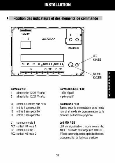
Bornes à vis :1 alimentation 12/24 V ca/cc2 alimentation 12/24 V ca/cc
CI commune entrées KNX / EIBI1 entrée 1 sans potentielI2 entrée 2 sans potentielI3 entrée 3 sans potentiel
L1 commune relais 1NO1 contact NO relais 1L2 commune relais 2NO2 contact NO relais 2
Bornes Bus KNX / EIB:- pôle négatif+ pôle positif
Bouton KNX / EIBTouche pour la commutation entre modenormal et mode de programmation ou ladétection de l'adresse physique
Led KNX / EIBLED de signalisation : mode normal (ledARRET) ou mode adressage (led MARCHE). S'éteint automatiquement après la détection/programmation de l'adresse physique
Position des indicateurs et des éléments de commande
LEDKNX/EIB
BoutonKNX/EIB
KNX/EIB
1 2
12/24V
CI I3 I2 I1
IN OUT2 OUT1
GWXXXXX
NO2 L2 NO1 L1
+ –

INSTALLATION
32
Cet appareil doit être utilisé pour être installé de manière fixe dans des pièces fermées, desespaces secs, dans des boîtes encastrables ou fixées au mur.• L'appareil ne peut pas être installé dans la même boîte que d'autres dispositifs à 230V. • L'appareil doit être installé et mis en service par un installateur autorisé.• Il faut observer les normes en vigueur en matière de sécurité et de prévention des
accidents.• Il ne faut pas ouvrir l'appareil. Les éventuels appareils défectueux doivent être envoyés
au siège compétent.
Avertissements pour l’installation
Monter le lecteur exclusivement en position horizontale.
Montage et connexion

FRANÇAIS
INSTALLATION
33
FRANÇAIS
Pour effectuer la mise en service, il faut pouvoir accéder au "Bouton KNX / EIB" decommutation entre mode normal et mode de programmation, qui se trouve sur le côtépostérieur de l'enveloppe. En phase d'installation, prévoir des câbles de connexion suffisamment longs pour qu'onpuisse extraire de la boîte encastrable l'ensemble appareil / châssis de montage.
Description générale
La borne Bus KNX / EIB (comprise dans la fourniture) est adaptée pour un conducteurà un seul fil de Ø 0,6-0,8 mm.
Connexion du câble bus à la borne KNX / EIB
Insérer la borne Bus KNX / EIB, connectée au préalable au câble bus, dans la fente deguidage du coupleur bus intégré qui se trouve du côté postérieur du dispositif. Faire glisser la borne bus jusqu'à l'arrêt.
Connexion du lecteur de transponder à la ligne bus
Le lecteur de transponder doit être configuré avec un des logiciels de gestion des accès"GWHotel" ou "GWAccess" pour la configuration des cartes transponder et l'attribution desdroits d'accès.
Configuration

INSTALLATION
34
Sont respectées les normes EN 61000-6-3, EN 61000-6-1 et EN 50090-2-2.
Exigences EMC
Suivant la norme EN 50090-2-2.Température ambiante pendant le fonctionnement : 0°C + 45°C.Température de stockage : - 20 + 55°C.Humidité relative : max 90%.
Conditions d'emploi
Homologué KNX/EIB.
Homologation
Conformément à la directive CE (bâtiments pour l'habitation et l'industrie), directive bassetension.
Marque CE
Degré de pollution (suivant IEC 60664-1): 2.Degré de protection (suivant EN 60529): IP 20.Classe de protection (suivant IEC 61140): III . Classe de surtension (suivant IEC 664-1) : III .Bus : tension de sécurité SELV DC 24V.Satisfait les normes EN 50090 et IEC 664-1.
Sécurité électrique

FRANÇAIS
CARACTÉRISTIQUES TECHNIQUES
35
FRANÇAIS
AlimentationTension BUS KNX / EIB: 29V cc SELVAbsorption à partir du BUS: 5mATension auxiliaire externe: 12/24V ca/cc +/- 10%Absorption max de tension auxiliaire : 150mA
Entrées KNX / EIB3 contacts sans potentiell'alimentation est fournie de l'intérieur 24V 1mA
Sorties vers le relais2 contacts NO 2A cosϕ 0,6 24V caCanal 1 : emploi général ou commande électroserrureCanal 2 : lumière de service ou emploi général
Lecteur de transponderChip lecture/écriture transponder Atmel/TemicAlimentation fournie de l'intérieur 5V dcFréquence de travail 125KHz
Eléments de commandeBouton pour commutation mode normal / mode programmation
IndicateursPorte-carte éclairé


Bolsillo Transponder
E S P A Ñ O L

38
Atención! La seguridad del aparato está garantizada solo ateniéndose a las instrucciones
indicadas aquí. Por lo tanto es necesario leerlas y conservarlas.
Los productos Chorus deben instalarse conforme a lo previsto por la norma CEI 64-8 para
los aparatos para uso doméstico y similar, en ambientes sin polvo y donde no sea necesaria
una protección especial contra la penetración de agua.
La organización de venta GEWISS se encuentra a disposición para aclaraciones e
informaciones técnicas.
Gewiss SpA se reserva el derecho de aportar cambios al producto descrito en este manual
en cualquier momento y sin preaviso.
Atención - Importante
ESPAÑOL
ÍNDICE
39
ESPAÑOL
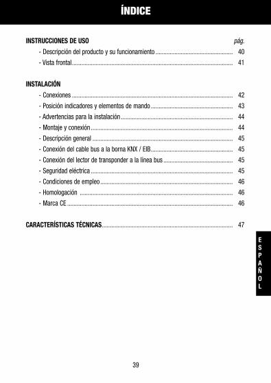
INSTRUCCIONES DE USO pág.
- Descripción del producto y su funcionamiento ................................................. 40
- Vista frontal...................................................................................................... 41
INSTALACIÓN
- Conexiones ...................................................................................................... 42
- Posición indicadores y elementos de mando .................................................... 43
- Advertencias para la instalación ....................................................................... 44
- Montaje y conexión .......................................................................................... 44
- Descripción general ......................................................................................... 45
- Conexión del cable bus a la borna KNX / EIB.................................................... 45
- Conexión del lector de transponder a la línea bus ............................................ 45
- Seguridad eléctrica .......................................................................................... 45
- Condiciones de empleo .................................................................................... 46
- Homologación ................................................................................................. 46
- Marca CE ......................................................................................................... 46
CARACTERÍSTICAS TÉCNICAS................................................................................... 47

INSTRUCCIONES DE USO
40
Descripción del producto y su funcionamientoEl bolsillo porta transponder GW1X 682 es un dispositivo KNX / EIB que permite elreconocimiento de las tarjetas transponder y el informe de las presencias de supervisión(ej. recepción);
El aparato está dotado de tres entradas físicas ON/OFF disponibles para el control del switchde puerta abierta/cerrada o de otros avisos (contacto ventana, tirante alarma baño etc).En el dispositivo hay presentes dos relés 24 Vac, que utilizar por ejemplo para el control dela cerradura de la puerta, para el mando de la "luz de cortesía" para la habilitación decargas eléctricas presentes en el ambiente o para otro uso.
La lectura del transponder se efectúa introduciendo la tarjeta en el apropiado bolsillo frontal.
La configuración del equipo, dirección física, parámetros y objetos de comunicación seefectúa mediante el software ETS (EIB tool Software). La base de datos del producto sedescarga libremente desde el sitio www.gewiss.com, (área productos - Domotics).
El bolsillo porta transponder se coloca en el interior de cajas empotrables o de paredestándares, y se instala en los soportes de la serie Chorus en el espacio de tres módulos.

ESPAÑOL
INSTRUCCIONES DE USO
41
ESPAÑOL
Vista frontal
Bolsillo iluminado para la introducción de las tarjetas transponder
En ausencia de la tarjeta, la retroiluminación ON/OFF del bolsillo porta distintivo es unparámetro libremente configurable por ETS;con la tarjeta introducida la retroiluminación es siempre OFF.

INSTALACIÓN
42
Línea bus: Terminal KNX / EIB, conductor Ø 0,6-0,8 mm.Alimentación 12/24V ac/dc: Bornas con tornillo, conductor sección máx. 1,5 mm2
Salidas ON/OFF: Bornas con tornillo, conductor sección máx. 1,5 mm2
Entradas ON/OFF sin potencial: Bornas con tornillo, conductor sección máx. 1,5 mm2
Conexiones
BUS / KNX
Interfaz KNX / EIB
OUT 2 OUT 1
Máx 24V ac/dc 2A
Máx 24V ac/dc 2A
IN 3
IN 2
IN 1
CI I3 I2 I1 L2 L1
Alimentación 12/24V ac/dc
Entradas ON / OFF tradicionales parala gestión de mandos KNX / EIB

ESPAÑOL
INSTALACIÓN
43
ESPAÑOL
Bornas de tornillo:1 alimentación 12/24 V ac/dc2 alimentación 12/24 V ac/dc
CI común entradas KNX / EIBI1 entrada 1 sin potencialI2 entrada 2 sin potencialI3 entrada 3 sin potencial
L1 común relé 1NO1 contacto NA relé 1L2 común relé 2NO2 contacto NA relé 2
Bornas Bus KNX / EIB:- polo negativo + polo positivo
Pulsador KNX / EIBTecla para la conmutación entre modonormal o modo programación o la detecciónde la dirección física
Led KNX / EIBLED de aviso entre modo normal (lef off) omodo dirección (led on). Se apaga automáticamente después de ladetección / programación de la direcciónfísica
Posición indicadores y elementos de mando
LED KNX / EIB
PulsadorKNX / EIB
KNX/EIB
1 2
12/24V
CI I3 I2 I1
IN OUT2 OUT1
GWXXXXX
NO2 L2 NO1 L1
+ –

INSTALACIÓN
44
El aparato debe emplearse para instalación fija en ambientes cerrados, espacios secos, encajas empotrables o de pared.• El aparato no puede ser instalado en la misma caja junto con los dispositivos a 230V. • El aparato debe ser instalado y puesto en funcionamiento por un instalador habilitado.• Deben ser observadas las normas en vigor en materia de seguridad y prevención contra
accidentes.• El aparato no debe abrirse. Eventuales aparatos defectuosos deberán entregarse a la
sede competente.
Advertencias para la instalación
Montar el lector exclusivamente en posición horizontal.
Montaje y conexión

ESPAÑOL
INSTALACIÓN
45
ESPAÑOL
Para efectuar la puesta en servicio es necesario acceder al "Pulsador KNX / EIB" para laconmutación entre modo normal y modo programación que se encuentra en el ladoposterior de la caja. En fase de instalación prever longitudes de conexión de los cables que permitan laextracción del conjunto aparato/chasis de montaje de la caja empotrable.
Descripción general
La borna Bus KNX / EIB (incluida en el suministro) se adapta a un monoconductor conØ 0,6-0,8 mm.
Conexión del cable bus a la borna KNX / EIB
Introducir la borna Bus KNX / EIB, precedentemente conectada al cable bus, en la ranuraguía del acoplador bus integrado que se encuentra en el lado posterior del dispositivo. Desplazar la borna bus hasta la parada.
Conexión del lector de transponder a la línea bus
El lector de transpondedor debe estar configurado trámite uno de los software de gestiónentradas "GWHotel" o "GWAccess" para la configuración de las tarjetas transpondedor y laasignación de los derechos de entrada.
Configuración

INSTALACIÓN
46
Respetados EN 61000-6-3, EN 61000-6-1 y EN 50090-2-2.
Requisitos EMC
Según norma EN 50090-2-2.Temperatura ambiente durante el funcionamiento: 0°C + 45°C.Temperatura de almacenaje: - 20 + 55°C.Humedad relativa: máx 90%.
Condiciones de empleo
Homologado KNX/EIB.
Homologación
Conforme a la directiva CE (construcción de las viviendas e industrial), directiva sobre labaja tensión.
Marca CE
Grado de contaminación (según IEC 60664-1): 2.Grado de protección (según EN 60529): IP 20.Grado de protección (según IEN 61140): III. Grado de sobretensión (según IEN 664-1): III.Bus: tensión de seguridad SELV DC 24V.Cumple EN 50090 y IEC 664-1.
Seguridad eléctrica
ESPAÑOL
CARACTERÍSTICAS TÉCNICAS
47
ESPAÑOL
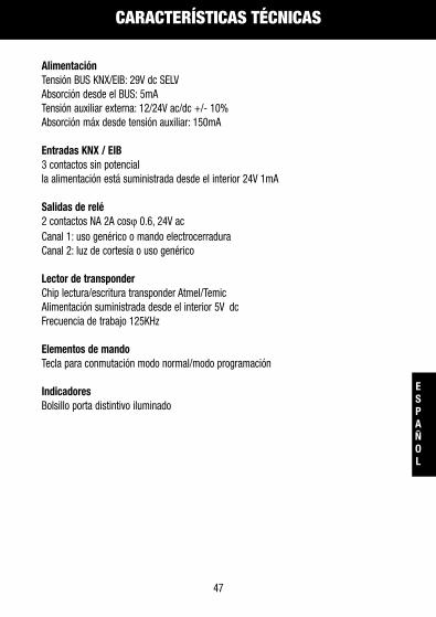
AlimentaciónTensión BUS KNX/EIB: 29V dc SELVAbsorción desde el BUS: 5mATensión auxiliar externa: 12/24V ac/dc +/- 10%Absorción máx desde tensión auxiliar: 150mA
Entradas KNX / EIB3 contactos sin potencialla alimentación está suministrada desde el interior 24V 1mA
Salidas de relé2 contactos NA 2A cosϕ 0.6, 24V acCanal 1: uso genérico o mando electrocerraduraCanal 2: luz de cortesía o uso genérico
Lector de transponderChip lectura/escritura transponder Atmel/TemicAlimentación suministrada desde el interior 5V dcFrecuencia de trabajo 125KHz
Elementos de mandoTecla para conmutación modo normal/modo programación
IndicadoresBolsillo porta distintivo iluminado


Transponder Kartenschlitz
D E U T S C H

50
Achtung ! Die Gerätesicherheit ist nur dann gegeben, wenn die nachfolgenden
Anweisungen eingehalten werden. Daher sind diese zu lesen, und aufzubewahren.
Die Produkte der Reihe Chorus müssen gemäß der Norm CEI 64-8 für Anwendung im
Wohnbereich oder ähnlich, in staubarmer Umgebung, wo kein besonderer Schutz gegen
Eindringen von Wasser erforderlich ist, installiert werden.
Die GEWISS Verkaufsabteilung steht für weitergehende Erläuterungen und technische
Informationen gerne zur Verfügung.
Gewiss S.p.A. behält sich das Recht vor, das in diesem Handbuch beschriebene Produkt
jederzeit und ohne Vorankündigung zu ändern.
Achtung - Wichtig
DEUTSCH
INHALTSVERZEICHNIS
51
DEUTSCH
BEDIENUNGSANWEISUNG Seite
- Produkt- und Funktionsbeschreibung............................................................... 52
- Frontansicht ..................................................................................................... 53
INSTALLATION
- Anschlüsse....................................................................................................... 54
- Position Anzeige- und Bedienelemente............................................................. 55
- Hinweise zur Installation .................................................................................. 56
- Montage und Anschluss ................................................................................... 56
- Allgemeine Beschreibung................................................................................. 57
- Anschluss des Buskabels an die Klemme KNX/EIB ........................................... 57
- Anschluss des Transponder-Lesers an die Busleitung....................................... 57
- Elektrische Sicherheit....................................................................................... 57
- Anwendungsbedingungen ................................................................................ 58
- Zulassung ....................................................................................................... 58
- CE-Kennzeichnung........................................................................................... 58
TECHNISCHE EIGENSCHAFTEN.................................................................................. 59

BEDIENUNGSANWEISUNG
52
Produkt- und FunktionsbeschreibungBei dem Kartenschlitz für Transponder GW1X 682 handelt es sich um ein KNX/EIB-Gerät zurErkennung von Transponder-Karten und der Mitteilung über präsente Überwachung (z.B.Rezeption);
Das Gerät ist mit drei physischen ON/OFF Eingängen ausgestattet, für die Kontrolle desTürschalters offen/geschlossen oder andere Signale (Fensterkontakt, AlarmglockeBadezimmer, usw.).Im Gerät befinden sich zwei 24 VAC Relais, die zur Steuerung von elektrischenTürschlössern, Steuerung der Zugangsbeleuchtung, Aktivierung elektrischer Verbraucher inder Umgebung oder zu anderen Einsatzzwecken zu verwenden sind.
Das Lesen des Transponders erfolgt durch Einführen der Karte in den Frontschlitz.
Die Konfiguration des Geräts, physikalische Adresse, Parameter undKommunikationsobjekte erfolgt über die ETS-Software (EIB Tool Software). DieProduktdatenbank kann kostenlos von der Website www.gewiss.com (Bereich Produkte -Domotics), herunter geladen werden.
Der Kartenschlitz wird innerhalb normaler Unterputz- oder Aufputz-Gehäuse positioniert,und mit Haltern der Chorus-Reihe mit einem Platzbedarf von drei Modulen installiert.

DEUTSCH
BEDIENUNGSANWEISUNG
53
DEUTSCH
Frontansicht
Beleuchteter Schlitz zum Einführen der Transponder-Karten
Bei Fehlen der Karte ist die Rückbeleuchtung EIN / AUS des Kartenschlitzes ein frei überETS programmierbarer Parameter; Bei eingeführter Karte ist die Rückbeleuchtung immer AUS.

INSTALLATION
54
Buslinie: Klemme KNX / EIB, Leiter Ø 0,6-0,8 mm.Stromversorgung 12/24V AC/DC: Schraubklemmen, max. Leiterquerschnitt 1,5 mm2
Ausgänge ON/OFF: Schraubklemmen, max. Leiterquerschnitt 1,5 mm2
Potentialfreie Eingänge ON/OFF: Schraubklemmen, max. Leiterquerschnitt 1,5 mm2
Anschlüsse
BUS / KNX
Schnittstelle KNX / EIB
OUT 2 OUT 1
Max 24V AC/DC 2A
Max 24V AC/DC 2A
IN 3
IN 2
IN 1
CI I3 I2 I1 L2 L1
Stromversorgung 12/24V AC/DC
Traditionelle ON/OFF Eingänge fürSteuerung der KNX/EIB-Befehle

DEUTSCH
INSTALLATION
55
DEUTSCH
Schraubklemmen:1 Stromversorgung 12/24 V AC/DC2 Stromversorgung 12/24 V AC/DC
CI Allgemeiner Eingang KNX/EIBI1 potentialfreier Eingang 1I2 potentialfreier Eingang 2I3 potentialfreier Eingang 3
L1 Allgemein Relais 1NO1 Kontakt NO Relais 1L2 Allgemein Relais 2NO2 Kontakt NO Relais 2
Bus KNX / EIB Klemmen:- Minuspol+ Pluspol
Taste KNX / EIBTaste für Umschaltung zwischen normalemModus oder Programmiermodus oderErfassung der physikalischen Adresse
LED KNX / EIBAnzeige-LED zwischen normalem Modus(LED aus) oder Adressiermodus (LED an). Sie schaltet sich automatisch nach demErfassen/Programmieren der physikalischenAdresse aus
Position Anzeige- und Bedienelemente
LEDKNX / EIB
TasteKNX / EIB
KNX/EIB
1 2
12/24V
CI I3 I2 I1
IN OUT2 OUT1
GWXXXXX
NO2 L2 NO1 L1
+ –
INSTALLATION
56
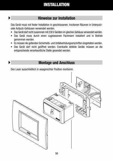
Das Gerät muss mit fester Installation in geschlossenen, trockenen Räumen in Unterputz-oder Aufputz-Gehäusen verwendet werden.• Das Gerät darf nicht zusammen mit 230 V Geräten im gleichen Gehäuse verwendet werden. • Das Gerät muss durch einen zugelassenen Fachmann installiert und in Betrieb
genommen werden.• Es müssen die geltenden Sicherheits- und Unfallverhütungvorschriften eingehalten werden.• Das Gerät darf nicht geöffnet werden. Eventuelle defekte Geräte müssen an die
entsprechende verantwortliche Stelle gesendet werden.
Hinweise zur Installation
Den Leser ausschließlich in waagerechter Position montieren.
Montage und Anschluss

DEUTSCH
INSTALLATION
57
DEUTSCH
Zur Inbetriebnahme muss die "Taste KNX / EIB" auf der Gehäuserückseite betätigt werden,um zwischen normalem Modus und Programmiermodus umzuschalten. Während der Installation muss ein ausreichend langes Anschlusskabel vorgesehen werden,mit dem es möglich ist, die Einheit aus Gerät und Montagerahmen aus demUnterputzgehäuse zu entnehmen.
Allgemeine Beschreibung
Die Busklemme KNX / EIB (mitgeliefert) eignet sich für einen einadrigen Leiter mit Ø0,6-0,8 mm.
Anschluss des Buskabels an die Klemme KNX / EIB
Die zuvor an das Buskabel angeschlossene Busklemme KNX / EIB in den integriertenFührungschlitz des Buskopplers auf der Geräterückseite einsetzen. Die Busklemme bis zum Anschlag einschieben.
Anschluss des Transponder-Lesers an die Busleitung
Der Transponder-Leser muss mit der Zugangsmanagement-Software "GWHotel" oder"GWAccess" für die Konfiguration der Transponder-Karten und Zuweisung derZugangsberechtigungen programmiert werden.
Konfiguration
INSTALLATION
58
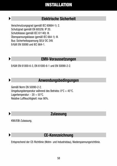
Erfüllt EN 61000-6-3, EN 61000-6-1 und EN 50090-2-2.
EMV-Voraussetzungen
Gemäß Norm EN 50090-2-2.Umgebungstemperatur während des Betriebs: 0°C + 45°C.Lagertemperatur: - 20 + 55°C.Relative Luftfeuchtigkeit: max 90%.
Anwendungsbedingungen
KNX/EIB-Zulassung.
Zulassung
Entsprechend der CE-Richtlinie (Wohn- und Industriebau), Niederspannungsrichtlinie.
CE-Kennzeichnung
Verschmutzungsgrad (gemäß IEC 60664-1): 2.Schutzgrad (gemäß EN 60529): IP 20.Schutzklasse (gemäß IEC 61140): III. Überspannungsklasse (gemäß IEC 664-1): III.Bus: Sicherheitsspannung SELV DC 24V.Erfüllt EN 50090 und IEC 664-1.
Elektrische Sicherheit

DEUTSCH
TECHNISCHE EIGENSCHAFTEN
59
DEUTSCH
StromversorgungSpannung KNX/EIB-Bus: 29V DC SELVStromaufnahme des Bus: 5mAExterne Hilfsspannung: 12/24V AC/DC +/- 10%Maximale Aufnahme der Hilfsspannung: 150mA
KNX/EIB-Eingänge3 potentialfreie KontakteStromversorgung von innen 24V 1mA
Relaisausgänge2 Kontakte NO 2A cosϕ 0,6 24V ACKanal 1: Allgemeine Verwendung oder Steuerung elektrisches SchlossKanal 2: Zugangslicht oder allgemeine Verwendung
Transponder LesegerätLese-/Schreibchip Transponder Atmel/TemicStromversorgung von innen 5V DCBetriebsfrequenz 125 kHz
BedienelementeTaste für Umschaltung zwischen normalem Modus oder Programmiermodus
AnzeigenBeleuchteter Kartenschlitz

cod.
7.0
1.5
.120.4
ULT
IMA
RE
VIS
ION
E 0
3/2
011
+39 035 946 1118.30 - 12.30 / 14.00 - 18.00
lunedì ÷ venerdì - monday ÷ friday
+39 035 946 [email protected]
Ai sensi dell’articolo 9 comma 2 della Direttiva Europea 2004/108/CE si informa che responsabile dell’immissione del prodotto sul mercato Comunitario è:According to article 9 paragraph 2 of the European Directive 2004/108/EC, the responsible for placing the apparatus on the Community market is:GEWISS S.p.A Via A. Volta, 1 - 24069 Cenate Sotto (BG) Italy Tel: +39 035 946 111 Fax: +39 035 945 270 E-mail: [email protected]