Embed Size (px)
Citation preview
TECHNICAL DATA BOOK
CONTENTS
1. REFERENCE SERVICE MANUAL ·············································22. SPECIFICATIONS ······································································33. OUTLINES AND DIMENSIONS ···············································244. WIRING DIAGRAM ···································································445. REFRIGERANT SYSTEM DIAGRAM ······································586. PERFORMANCE CURVES ······················································637. CORRECTION FACTORS ························································658. APPLICABLE EXTENSION PIPE FOR EACH MODEL ··········669. AIR FLOW DATA ······································································75
10. NOISE CRITERION CURVES ··················································9011. OPTIONAL PARTS ··································································106
<Indoor unit>
[Model names]
R410A
PLA-RP·BA/BA2/BA3PEAD-RP·JA(L)PEA-RP·GAPKA-RP·HALPKA-RP·KALPCA-RP·KAPCA-RP·HAPSA-RP·GA
<Outdoor unit>[Model names]
SPLIT-TYPE, HEAT PUMP AIR CONDITIONERS
PUHZ-RP35/50/60/71VHA4PUHZ-RP100/125/140VKAPUHZ-RP100/125/140YKAPUHZ-RP200/250YKA
July 2009
INVERTER
kW Model
No. OCS16

2
1 REFERENCE SERVICE MANUAL
For information on service, please refer to the service manual as follows.
1-1. INDOOR UNIT SERVICE MANUAL
Model name Service Ref. Service Manual No.
PLA-RP35/50/60/71/100/125BAPLA-RP71/125/140BA2
PLA-RP35/50/60/71/100/125BA#2.UKPLA-RP71/125/140BA2.UK
OCH412OCB412
PLA-RP100BA3 PLA-RP100BA3 OCH459OCB459
PCA-RP50/60/71/100/125/140KA PCA-RP50/60/71/100/125/140KA OCH454OCB454
PCA-RP71/125HA PCA-RP71/125HA#1 OC329
PKA-RP35/50HAL PKA-RP35/50HAL OCH453OCB453
PKA-RP60/71/100KAL PKA-RP60/71/100KAL.TH OCH452OCB452
PSA-RP71/100/125/140GA PSA-RP71/100/125/140GA#1 OC332
PEAD-RP35/50/60/71/100/125/140JA(L) PEAD-RP35/50/60/71/100/125/140JA(L).UK HWE08130BWE08240
PEA-RP200/250/400/500GA PEA-RP200/250/400/500GA.TH-AFPEA-RP200/250GA.TH-AFMF HWE0708A
1-2. OUTDOOR UNIT
Model name Service Ref. Service Manual No.
PUHZ-RP35/50/60/71VHA4PUHZ-RP100/125/140VKAPUHZ-RP100/125/140YKAPUHZ-RP200/250YKA
PUHZ-RP35/50/60/71VHA4PUHZ-RP100/125/140VKAPUHZ-RP100/125/140YKAPUHZ-RP200/250YKA
OCH451OCB451
3
2 SPECIFICATIONS
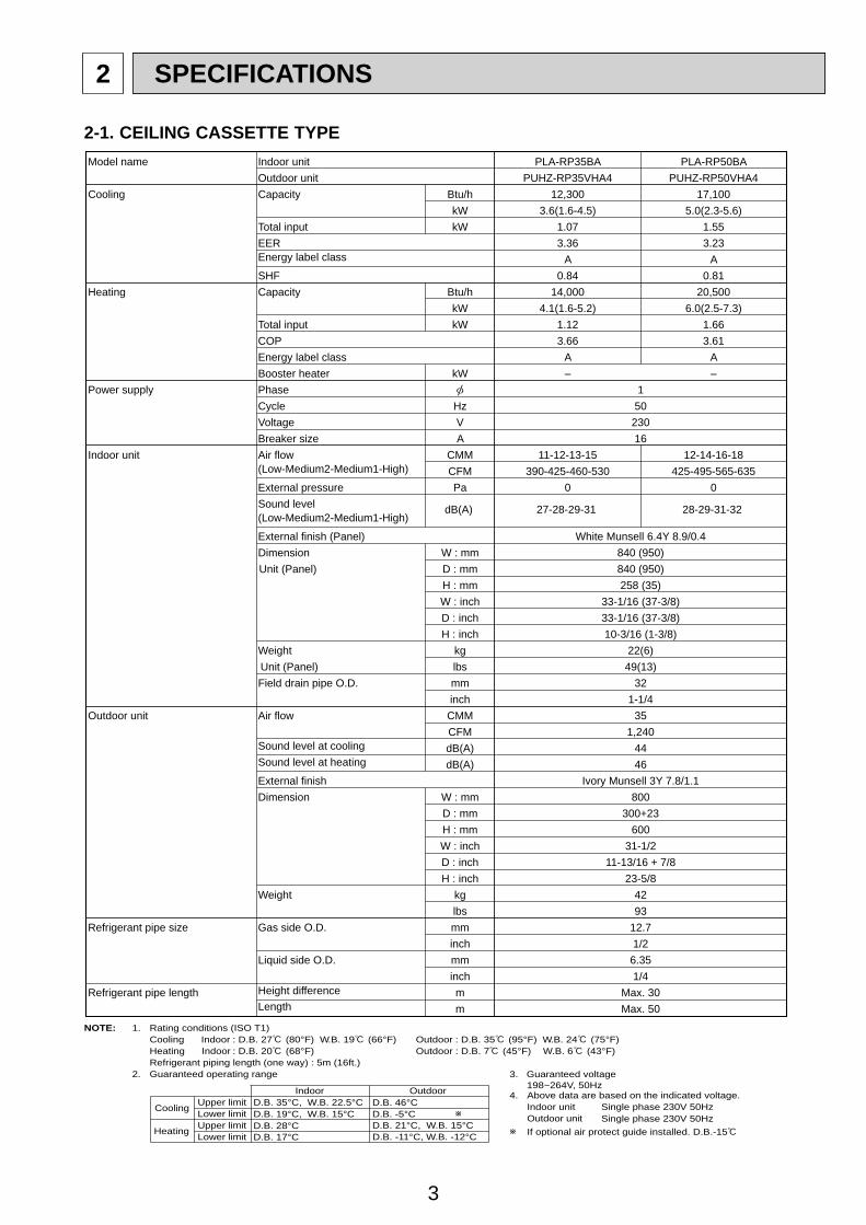
2-1. CEILING CASSETTE TYPEModel name Indoor unit PLA-RP35BA PLA-RP50BA
Outdoor unit PUHZ-RP35VHA4 PUHZ-RP50VHA4Cooling Capacity Btu/h 12,300 17,100
kW 3.6(1.6-4.5) 5.0(2.3-5.6)Total input kW 1.07 1.55EER 3.36 3.23Energy label class A ASHF 0.84 0.81
Heating Capacity Btu/h 14,000 20,500kW 4.1(1.6-5.2) 6.0(2.5-7.3)
Total input kW 1.12 1.66COP 3.66 3.61Energy label class A ABooster heater kW – –
Power supply Phase 1Cycle Hz 50Voltage V 230Breaker size A 16
Indoor unit Air flow CMM 11-12-13-15 12-14-16-18(Low-Medium2-Medium1-High) CFM 390-425-460-530 425-495-565-635External pressure Pa 0 0Sound level dB(A) 27-28-29-31 28-29-31-32(Low-Medium2-Medium1-High)
External finish (Panel) White Munsell 6.4Y 8.9/0.4Dimension W : mm 840 (950)Unit (Panel) D : mm 840 (950)
H : mm 258 (35)W : inch 33-1/16 (37-3/8)D : inch 33-1/16 (37-3/8)H : inch 10-3/16 (1-3/8)
Weight kg 22(6)Unit (Panel) lbs 49(13)Field drain pipe O.D. mm 32
inch 1-1/4Outdoor unit Air flow CMM 35
CFM 1,240Sound level at cooling dB(A) 44Sound level at heating dB(A) 46External finish Ivory Munsell 3Y 7.8/1.1Dimension W : mm 800
D : mm 300+23H : mm 600W : inch 31-1/2D : inch 11-13/16 + 7/8H : inch 23-5/8
Weight kg 42lbs 93
Refrigerant pipe size Gas side O.D. mm 12.7inch 1/2
Liquid side O.D. mm 6.35inch 1/4
Refrigerant pipe length Height difference m Max. 30Length m Max. 50
NOTE: 1. Rating conditions (ISO T1)Cooling Indoor : D.B. 27 (80°F) W.B. 19 (66°F) Outdoor : D.B. 35 (95°F) W.B. 24 (75°F)Heating Indoor : D.B. 20 (68°F) Outdoor : D.B. 7 (45°F) W.B. 6 (43°F)Refrigerant piping length (one way) : 5m (16ft.)
2. Guaranteed operating range
Indoor Outdoor
Cooling Upper limit D.B. 35°C, W.B. 22.5°C D.B. 46°CLower limit D.B. 19°C, W.B. 15°C D.B. -5°C
Heating Upper limit D.B. 28°C D.B. 21°C, W.B. 15°CLower limit D.B. 17°C D.B. -11°C, W.B. -12°C
4. Above data are based on the indicated voltage.
If optional air protect guide installed. D.B.-15
Indoor unit Single phase 230V 50HzSingle phase 230V 50HzOutdoor unit
3. Guaranteed voltage 198~264V, 50Hz
4
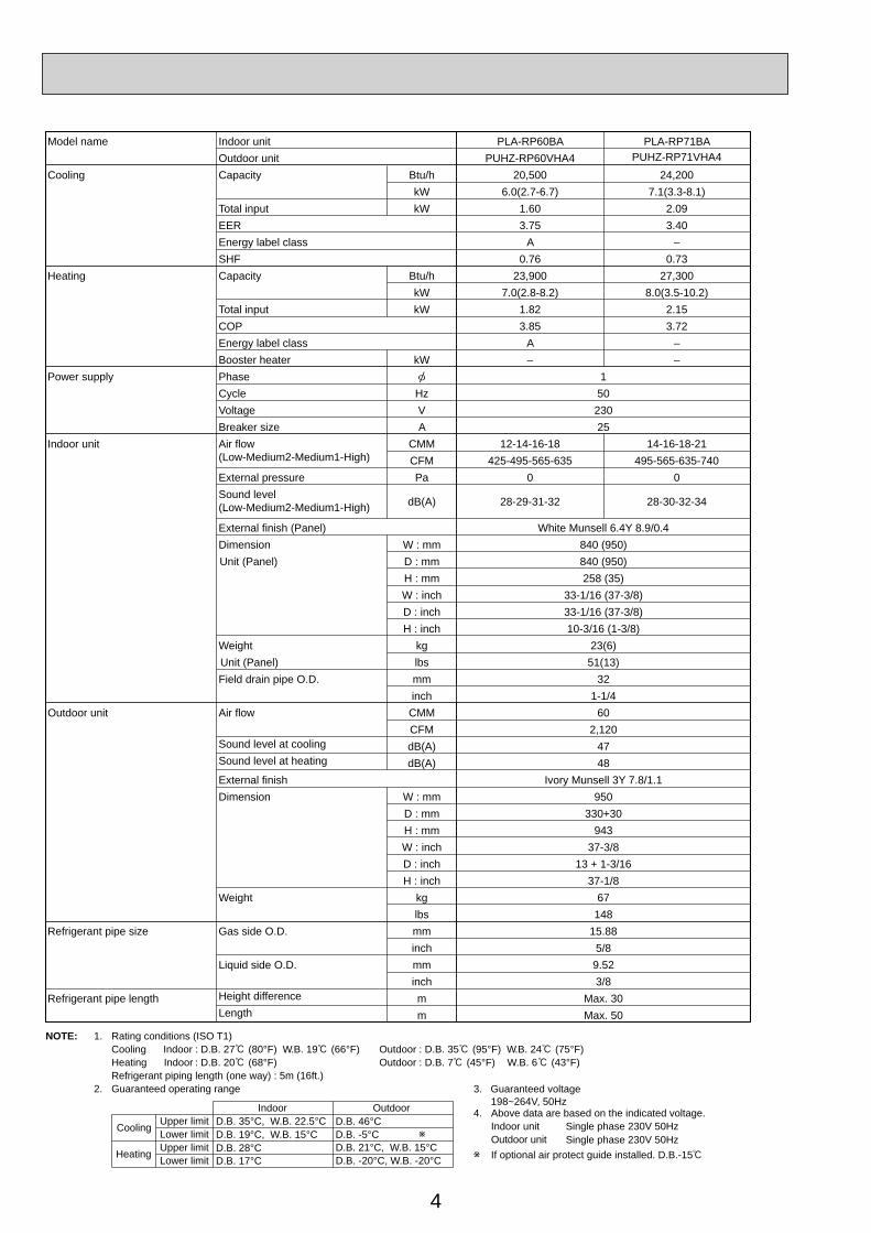
Model name Indoor unit PLA-RP60BA PLA-RP71BAOutdoor unit PUHZ-RP60VHA4 PUHZ-RP71VHA4
Cooling Capacity Btu/h 20,500 24,200kW 6.0(2.7-6.7) 7.1(3.3-8.1)
Total input kW 1.60 2.09EER 3.75 3.40Energy label class A –SHF 0.76 0.73
Heating Capacity Btu/h 23,900 27,300kW 7.0(2.8-8.2) 8.0(3.5-10.2)
Total input kW 1.82 2.15COP 3.85 3.72Energy label class A –Booster heater kW – –
Power supply Phase 1Cycle Hz 50Voltage V 230Breaker size A 25
Indoor unit Air flow CMM 12-14-16-18 14-16-18-21(Low-Medium2-Medium1-High) CFM 425-495-565-635 495-565-635-740External pressure Pa 0 0Sound level
dB(A) 28-29-31-32 28-30-32-34(Low-Medium2-Medium1-High)
External finish (Panel) White Munsell 6.4Y 8.9/0.4Dimension W : mm 840 (950)Unit (Panel) D : mm 840 (950)
H : mm 258 (35)W : inch 33-1/16 (37-3/8)D : inch 33-1/16 (37-3/8)H : inch 10-3/16 (1-3/8)
Weight kg 23(6)Unit (Panel) lbs 51(13)Field drain pipe O.D. mm 32
inch 1-1/4Outdoor unit Air flow CMM 60
CFM 2,120Sound level at cooling dB(A) 47Sound level at heating dB(A) 48External finish Ivory Munsell 3Y 7.8/1.1Dimension W : mm 950
D : mm 330+30H : mm 943W : inch 37-3/8D : inch 13 + 1-3/16H : inch 37-1/8
Weight kg 67lbs 148
Refrigerant pipe size Gas side O.D. mm 15.88inch 5/8
Liquid side O.D. mm 9.52inch 3/8
Refrigerant pipe length Height difference m Max. 30Length m Max. 50
NOTE: 1. Rating conditions (ISO T1)Cooling Indoor : D.B. 27 (80°F) W.B. 19 (66°F) Outdoor : D.B. 35 (95°F) W.B. 24 (75°F)Heating Indoor : D.B. 20 (68°F) Outdoor : D.B. 7 (45°F) W.B. 6 (43°F)Refrigerant piping length (one way) : 5m (16ft.)
2. Guaranteed operating range
Indoor Outdoor
Cooling Upper limit D.B. 35°C, W.B. 22.5°C D.B. 46°CLower limit D.B. 19°C, W.B. 15°C D.B. -5°C
Heating Upper limit D.B. 28°C D.B. 21°C, W.B. 15°CLower limit D.B. 17°C D.B. -20°C, W.B. -20°C
4. Above data are based on the indicated voltage.
If optional air protect guide installed. D.B.-15
Indoor unit Single phase 230V 50HzSingle phase 230V 50HzOutdoor unit
3. Guaranteed voltage 198~264V, 50Hz
5
NOTE: 1. Rating conditions (ISO T1)Cooling Indoor : D.B. 27 (80°F) W.B. 19 (66°F) Outdoor : D.B. 35 (95°F) W.B. 24 (75°F)Heating Indoor : D.B. 20 (68°F) Outdoor : D.B. 7 (45°F) W.B. 6 (43°F)Refrigerant piping length (one way) : 5m (16ft.)
2. Guaranteed operating range
Indoor Outdoor
Cooling Upper limit D.B. 35°C, W.B. 22.5°C D.B. 46°CLower limit D.B. 19°C, W.B. 15°C D.B. -5°C
Heating Upper limit D.B. 28°C D.B. 21°C, W.B. 15°CLower limit D.B. 17°C D.B. -20°C, W.B. -20°C
4. Above data are based on the indicated voltage.
If optional air protect guide installed. D.B.-15
Indoor unit Single phase 230V 50HzSingle phase 230V 50HzOutdoor unit
3. Guaranteed voltage 198~264V, 50Hz
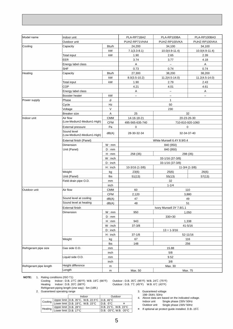
Model name Indoor unit PLA-RP71BA2 PLA-RP100BA3Outdoor unit PUHZ-RP71VHA4 PUHZ-RP100VKA
Cooling Capacity Btu/h 24,200 34,100kW 7.1(3.3-8.1) 10.0(4.9-11.4)
Total input kW 1.90 2.39EER 3.74 4.18Energy label class A ASHF 0.73 0.74
Heating Capacity Btu/h 27,300 38,200kW 8.0(3.5-10.2) 11.2(4.5-14.0)
Total input kW 1.90 2.43COP 4.21
PLA-RP100BAPUHZ-RP100VKA
34,10010.0(4.9-11.4)
2.653.77
–0.74
38,20011.2(4.5-14.0)
2.794.01 4.61
Energy label class A –Booster heater kW – –
A–
Power supply Phase 1Cycle Hz 50Voltage V 230Breaker size A 3225
23(6)51(13)
25(6)55(13)
26(6)57(13)
Indoor unit Air flow CMM 14-16-18-21(Low-Medium2-Medium1-High) CFM 495-565-635-740External pressure Pa 0Sound level dB(A) 28-30-32-34
20-23-26-30710-810-920-1060
0
32-34-37-40(Low-Medium2-Medium1-High)
External finish (Panel) White Munsell 6.4Y 8.9/0.4Dimension W : mm 840 (950)Unit (Panel) D : mm 840 (950)
H : mm 258 (35) 298 (35)W : inch 33-1/16 (37-3/8)D : inch 33-1/16 (37-3/8)H : inch 10-3/16 (1-3/8) 11-3/4 (1-3/8)
Weight kgUnit (Panel) lbsField drain pipe O.D. mm 32
inch 1-1/4Outdoor unit Air flow CMM 110
CFM 3,88060
2,120Sound level at cooling dB(A) 47Sound level at heating dB(A) 48
4951
External finish Ivory Munsell 3Y 7.8/1.1Dimension W : mm 950
D : mm 330+30H : mm 943 1,338
1,050
W : inch 41-5/1637-3/8D : inch 13 + 1-3/16H : inch 37-1/8 52-11/16
Weight kg 67 116lbs 148 256
Refrigerant pipe size Gas side O.D. mm 15.88inch 5/8
Liquid side O.D. mm 9.52inch 3/8
Refrigerant pipe length Height difference m Max. 30Length m Max. 75Max. 50
6
NOTE: 1. Rating conditions (ISO T1)Cooling Indoor : D.B. 27 (80°F) W.B. 19 (66°F) Outdoor : D.B. 35 (95°F) W.B. 24 (75°F)Heating Indoor : D.B. 20 (68°F) Outdoor : D.B. 7 (45°F) W.B. 6 (43°F)Refrigerant piping length (one way) : 5m (16ft.)
2. Guaranteed operating range
Indoor Outdoor
Cooling Upper limit D.B. 35°C, W.B. 22.5°C D.B. 46Lower limit D.B. 19°C, W.B. 15°C D.B. -5
Heating Upper limit D.B. 28°C D.B. 21 , W.B. 15Lower limit D.B. 17°C D.B. -20 , W.B. -20
4. Above data are based on the indicated voltage.
If optional air protect guide installed. D.B.-15
Indoor unit Single phase 230V 50HzSingle phase 230V 50HzOutdoor unit
3. Guaranteed voltage 198~264V, 50Hz
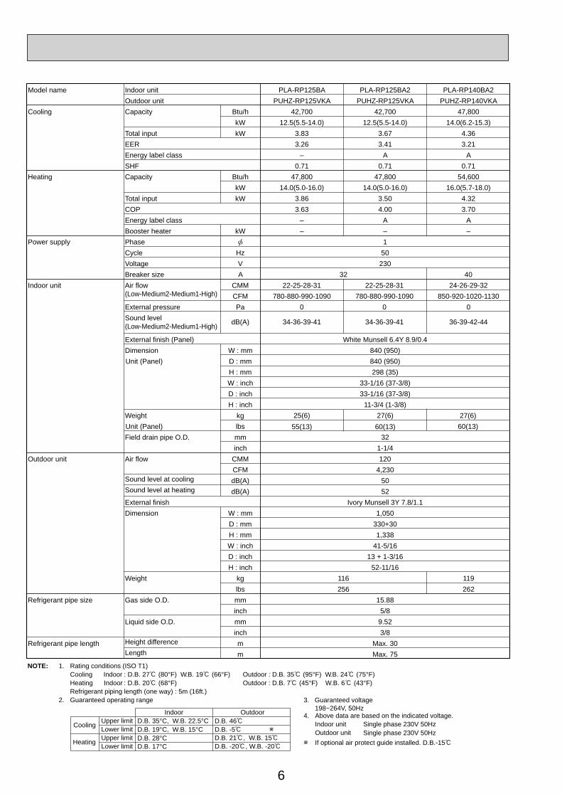
Model name Indoor unit PLA-RP125BA PLA-RP125BA2 PLA-RP140BA2Outdoor unit PUHZ-RP125VKA PUHZ-RP125VKA PUHZ-RP140VKA
Cooling Capacity Btu/h 42,700 42,700 47,800kW 12.5(5.5-14.0) 12.5(5.5-14.0) 14.0(6.2-15.3)
Total input kW 3.83 3.67 4.36EER 3.26 3.41 3.21Energy label class – A ASHF 0.71 0.71 0.71
Heating Capacity Btu/h 47,800 47,800 54,600kW 14.0(5.0-16.0) 14.0(5.0-16.0) 16.0(5.7-18.0)
Total input kW 3.86 3.50 4.32COP 3.63 4.00 3.70Energy label class – A ABooster heater kW – – –
Power supply Phase 1Cycle Hz 50Voltage V 230Breaker size A 32
25(6)55(13)
27(6)60(13)
40Indoor unit Air flow CMM 22-25-28-31 22-25-28-31
(Low-Medium2-Medium1-High) CFM 780-880-990-1090 780-880-990-1090External pressure Pa 0 0Sound level dB(A) 34-36-39-41 34-36-39-41
24-26-29-32850-920-1020-1130
0
36-39-42-44(Low-Medium2-Medium1-High)
External finish (Panel) White Munsell 6.4Y 8.9/0.4Dimension W : mm 840 (950)Unit (Panel) D : mm 840 (950)
H : mm 298 (35)W : inch 33-1/16 (37-3/8)D : inch 33-1/16 (37-3/8)H : inch 11-3/4 (1-3/8)
Weight kg 27(6)Unit (Panel) lbs 60(13)Field drain pipe O.D. mm 32
inch 1-1/4Outdoor unit Air flow CMM 120
CFM 4,230Sound level at cooling dB(A) 50Sound level at heating dB(A) 52External finish Ivory Munsell 3Y 7.8/1.1Dimension W : mm 1,050
D : mm 330+30H : mm 1,338W : inch 41-5/16D : inch 13 + 1-3/16H : inch 52-11/16
Weight kg 116 119lbs 256 262
Refrigerant pipe size Gas side O.D. mm 15.88inch 5/8
Liquid side O.D. mm 9.52inch 3/8
Refrigerant pipe length Height difference m Max. 30Length m Max. 75

7
Model name Indoor unit PLA-RP100BA PLA-RP100BA3Outdoor unit PUHZ-RP100YKA PUHZ-RP100YKA
Cooling Capacity Btu/h 34,100 34,100kW 10.0(4.9-11.4) 10.0(4.9-11.4)
Total input kW 2.65 2.39EER 3.77 4.18Energy label class – ASHF 0.74 0.74
Heating Capacity Btu/h 38,200 38,200kW 11.2(4.5-14.0) 11.2(4.5-14.0)
Total input kW 2.79 2.43COP 4.01 4.61Energy label class – ABooster heater kW – –
Power supply Phase 3Cycle Hz 50Voltage V 400Breaker size A 16
Indoor unit Air flow CMM 20-23-26-30 20-23-26-30(Low-Medium2-Medium1-High) CFM 710-810-920-1,060 710-810-920-1,060External pressure Pa 0 0Sound level dB(A) 32-34-37-40 32-34-37-40(Low-Medium2-Medium1-High)
External finish (Panel) White Munsell 6.4Y 8.9/0.4Dimension W : mm 840 (950)Unit (Panel) D : mm 840 (950)
H : mm 298 (35)W : inch 33-1/16 (37-3/8)D : inch 33-1/16 (37-3/8)H : inch 11-3/4 (1-3/8)
Weight kg 25 (6)Unit (Panel) lbs 55 (13)
26 (6)57 (13)
Field drain pipe O.D. mm 32inch 1-1/4
Outdoor unit Air flow CMM 110CFM 3,880
Sound level at cooling dB(A) 49Sound level at heating dB(A) 51External finish Ivory Munsell 3Y 7.8/1.1Dimension W : mm 1,050
D : mm 330+30H : mm 1,338W : inch 41-5/16D : inch 13 + 1-3/16H : inch 52-11/16
Weight kg 124lbs 273
Refrigerant pipe size Gas side O.D. mm 15.88inch 5/8
Liquid side O.D. mm 9.52inch 3/8
Refrigerant pipe length Height difference m Max. 30Length m Max. 75
NOTE: 1. Rating conditions (ISO T1)Cooling Indoor : D.B. 27 (80°F) W.B. 19 (66°F) Outdoor : D.B. 35 (95°F) W.B. 24 (75°F)Heating Indoor : D.B. 20 (68°F) Outdoor : D.B. 7 (45°F) W.B. 6 (43°F)Refrigerant piping length (one way) : 5m (16ft.)
2. Guaranteed operating range
Indoor Outdoor
Cooling Upper limit D.B. 35°C, W.B. 22.5°C D.B. 46°CLower limit D.B. 19°C, W.B. 15°C D.B. -5°C
Heating Upper limit D.B. 28°C D.B. 21°C, W.B. 15°CLower limit D.B. 17°C D.B. -20°C, W.B. -20°C
4. Above data are based on the indicated voltage.Indoor unit Single phase 230V 50Hz
3 phase 400V 50HzOutdoor unit
Indoor unit 198~264V, 50Hz342~457V, 50HzOutdoor unit
3. Guaranteed voltage
If optional air protect guide installed. D.B.-15

8
Model name Indoor unit PLA-RP125BA PLA-RP125BA2 PLA-RP140BA2Outdoor unit PUHZ-RP125YKA PUHZ-RP125YKA PUHZ-RP140YKA
Cooling Capacity Btu/hkW
Total input kWEEREnergy label class
SHFHeating Capacity Btu/h
kWTotal input kWCOPEnergy label class
Booster heater kWPower supply Phase 3
Cycle Hz 50Voltage V 400Breaker size A 16
Indoor unit Air flow CMM(Low-Medium2-Medium1-High) CFMExternal pressure PaSound level dB(A)(Low-Medium2-Medium1-High)
External finish (Panel)Dimension W : mmUnit (Panel) D : mm
H : mmW : inchD : inchH : inch
Weight kgUnit (Panel) lbsField drain pipe O.D. mm
inchOutdoor unit Air flow CMM
CFMSound level at cooling dB(A)Sound level at heating dB(A)External finishDimension W : mm
D : mmH : mmW : inchD : inchH : inch
Weight kg 126 132lbs 278 291
Refrigerant pipe size Gas side O.D. mm 15.88inch 5/8
Liquid side O.D. mm 9.52inch 3/8
Refrigerant pipe length Height difference m Max. 30Length m Max. 75
42,700 42,700 47,80012.5(5.5-14.0) 12.5(5.5-14.0) 14.0(6.2-15.3)
3.83 3.67 4.363.26 3.41 3.21
– A A0.71 0.71 0.71
47,800 47,800 54,60014.0(5.0-16.0) 14.0(5.0-16.0) 16.0(5.7-18.0)
3.86 3.50 4.323.63 4.00 3.70
– A A– – –
25(6)55(13)
27(6)60(13)
22-25-28-31 22-25-28-31780-880-990-1090 780-880-990-1090
0 0
34-36-39-41 34-36-39-41
24-26-29-32850-920-1020-1130
0
36-39-42-44
White Munsell 6.4Y 8.9/0.4840 (950)840 (950)298 (35)
33-1/16 (37-3/8)33-1/16 (37-3/8)
11-3/4 (1-3/8)27(6)60(13)
321-1/4120
4,2305052
Ivory Munsell 3Y 7.8/1.11,050
330+301,338
41-5/1613 + 1-3/16
52-11/16
NOTE: 1. Rating conditions (ISO T1)Cooling Indoor : D.B. 27 (80°F) W.B. 19 (66°F) Outdoor : D.B. 35 (95°F) W.B. 24 (75°F)Heating Indoor : D.B. 20 (68°F) Outdoor : D.B. 7 (45°F) W.B. 6 (43°F)Refrigerant piping length (one way) : 5m (16ft.)
2. Guaranteed operating range
Indoor Outdoor
Cooling Upper limit D.B. 35°C, W.B. 22.5°C D.B. 46°CLower limit D.B. 19°C, W.B. 15°C D.B. -5°C
Heating Upper limit D.B. 28°C D.B. 21°C, W.B. 15°CLower limit D.B. 17°C D.B. -20°C, W.B. -20°C
4. Above data are based on the indicated voltage.Indoor unit Single phase 230V 50Hz
3 phase 400V 50HzOutdoor unit
Indoor unit 198~264V, 50Hz342~457V, 50HzOutdoor unit
3. Guaranteed voltage
If optional air protect guide installed. D.B.-15
9
NOTE: 1. Rating conditions (ISO T1)Cooling Indoor : D.B. 27 (80°F) W.B. 19 (66°F) Outdoor : D.B. 35 (95°F) W.B. 24 (75°F)Heating Indoor : D.B. 20 (68°F) Outdoor : D.B. 7 (45°F) W.B. 6 (43°F)Refrigerant piping length (one way) : 5m (16ft.)
2. Guaranteed operating range
Indoor Outdoor
Cooling Upper limit D.B. 35°C, W.B. 22.5°C D.B. 46°CLower limit D.B. 19°C, W.B. 15°C D.B. -5°C
Heating Upper limit D.B. 28°C D.B. 21°C, W.B. 15°CLower limit D.B. 17°C D.B. -11°C, W.B. -12°C
4. Above data are based on the indicated voltage.
If optional air protect guide installed. D.B.-15
Indoor unit Single phase 230V 50HzSingle phase 230V 50HzOutdoor unit
3. Guaranteed voltage 198~264V, 50Hz
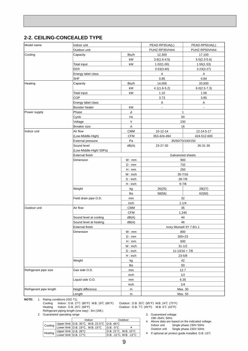
Model name Indoor unit PEAD-RP35JA(L) PEAD-RP50JA(L)Outdoor unit PUHZ-RP35VHA4 PUHZ-RP50VHA4
Cooling Capacity Btu/h 12,300 17,100kW 3.6(1.6-4.5) 5.0(2.3-5.6)
Total input kW 1.02(1.00) 1.55(1.53)EER 3.53(3.60) 3.23(3.27)Energy label class A ASHF 0.85 0.84
Heating Capacity Btu/h 14,000 20,500kW 4.1(1.6-5.2) 6.0(2.5-7.3)
Total input kW 1.10 1.56COP 3.73 3.85Energy label class A ABooster heater kW - -
Power supply Phase 1Cycle Hz 50Voltage V 230Breaker size A 16
Indoor unit Air flow CMM 10-12-14(Low-Middle-High) CFM 353-424-494External pressure Pa 35/50/70/100/150Sound level dB(A) 23-27-30(Low-Middle-High/ 50Pa)
12-14.5-17424-512-600
26-31-35
External finish Galvanized sheetsDimension W : mm 900
D : mm 732H : mm 250W : inch 35-7/16D : inch 28-7/8H : inch 9-7/8
Weight kg 26(25) 28(27)lbsmminch
58(56) 62(60)Field drain pipe O.D. 32
1-1/4Outdoor unit Air flow CMM 35
CFM 1,240Sound level at cooling dB(A) 44Sound level at heating dB(A) 46External finish Ivory Munsell 3Y 7.8/1.1Dimension W : mm 800
D : mm 300+23H : mm 600W : inch 31-1/2D : inch 11-13/16 + 7/8H : inch 23-5/8
Weight kg 42lbs 93
Refrigerant pipe size Gas side O.D. mm 12.7inch 1/2
Liquid side O.D. mm 6.35inch 1/4
Refrigerant pipe length Height difference m Max. 30Length m Max. 50
2-2. CEILING-CONCEALED TYPE
10
NOTE: 1. Rating conditions (ISO T1)Cooling Indoor : D.B. 27 (80°F) W.B. 19 (66°F) Outdoor : D.B. 35 (95°F) W.B. 24 (75°F)Heating Indoor : D.B. 20 (68°F) Outdoor : D.B. 7 (45°F) W.B. 6 (43°F)Refrigerant piping length (one way) : 5m (16ft.)
2. Guaranteed operating range
Indoor Outdoor
Cooling Upper limit D.B. 35°C, W.B. 22.5°C D.B. 46°CLower limit D.B. 19°C, W.B. 15°C D.B. -5°C
Heating Upper limit D.B. 28°C D.B. 21°C, W.B. 15°CLower limit D.B. 17°C D.B. -20°C, W.B. -20°C
4. Above data are based on the indicated voltage.
If optional air protect guide installed. D.B.-15
Indoor unit Single phase 230V 50HzSingle phase 230V 50HzOutdoor unit
3. Guaranteed voltage 198~264V, 50Hz
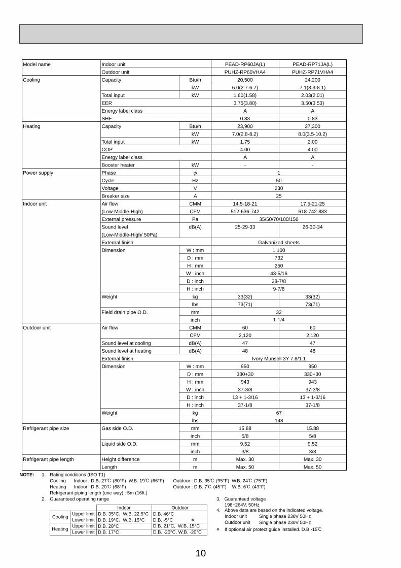
Model name Indoor unit PEAD-RP60JA(L) PEAD-RP71JA(L)Outdoor unit PUHZ-RP60VHA4 PUHZ-RP71VHA4
Cooling Capacity Btu/h 20,500 24,200kW 6.0(2.7-6.7) 7.1(3.3-8.1)
Total input kW 1.60(1.58) 2.03(2.01)EER 3.75(3.80) 3.50(3.53)Energy label class A ASHF 0.83 0.83
Heating Capacity Btu/h 23,900 27,300kW 7.0(2.8-8.2) 8.0(3.5-10.2)
Total input kW 1.75 2.00COP 4.00 4.00Energy label class A ABooster heater kW - -
Power supply Phase 1Cycle Hz 50Voltage V 230Breaker size A 25
Indoor unit Air flow CMM 14.5-18-21 17.5-21-25(Low-Middle-High) CFM 512-636-742 618-742-883External pressure Pa 35/50/70/100/150Sound level dB(A) 25-29-33 26-30-34(Low-Middle-High/ 50Pa)External finish Galvanized sheetsDimension W : mm 1,100
D : mm 732H : mm 250W : inch 43-5/16D : inch 28-7/8H : inch 9-7/8
Weight kg 33(32) 33(32)lbsmminch
73(71) 73(71)Field drain pipe O.D. 32
1-1/4Outdoor unit Air flow CMM 60 60
CFM 2,120 2,120Sound level at cooling dB(A) 47 47Sound level at heating dB(A) 48 48External finish Ivory Munsell 3Y 7.8/1.1Dimension W : mm 950 950
D : mm 330+30 330+30H : mm 943 943W : inch 37-3/8 37-3/8D : inch 13 + 1-3/16 13 + 1-3/16H : inch 37-1/8 37-1/8
Weight kg 67lbs 148
Refrigerant pipe size Gas side O.D. mm 15.88 15.88inch 5/8 5/8
Liquid side O.D. mm 9.52 9.52inch 3/8 3/8
Refrigerant pipe length Height difference m Max. 30 Max. 30Length m Max. 50 Max. 50
11
NOTE: 1. Rating conditions (ISO T1)Cooling Indoor : D.B. 27 (80°F) W.B. 19 (66°F) Outdoor : D.B. 35 (95°F) W.B. 24 (75°F)Heating Indoor : D.B. 20 (68°F) Outdoor : D.B. 7 (45°F) W.B. 6 (43°F)Refrigerant piping length (one way) : 5m (16ft.)
2. Guaranteed operating range
Indoor Outdoor
Cooling Upper limit D.B. 35°C, W.B. 22.5°C D.B. 46Lower limit D.B. 19°C, W.B. 15°C D.B. -5
Heating Upper limit D.B. 28°C D.B. 21 , W.B. 15Lower limit D.B. 17°C D.B. -20 , W.B. -20
4. Above data are based on the indicated voltage.
If optional air protect guide installed. D.B.-15
Indoor unit Single phase 230V 50HzSingle phase 230V 50HzOutdoor unit
3. Guaranteed voltage 198~264V, 50Hz
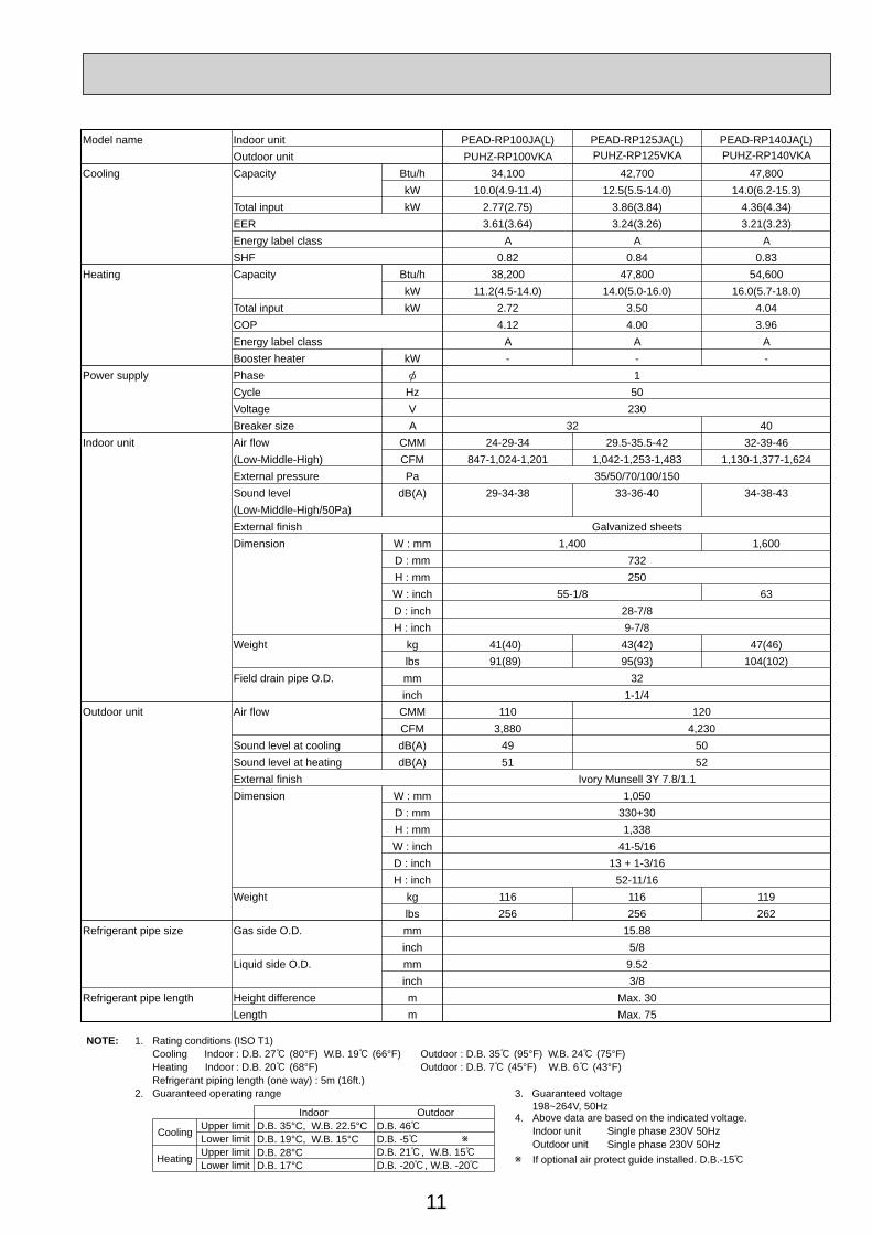
Model name Indoor unit PEAD-RP100JA(L) PEAD-RP125JA(L) PEAD-RP140JA(L)Outdoor unit PUHZ-RP100VKA PUHZ-RP125VKA PUHZ-RP140VKA
Cooling Capacity Btu/h 34,100 42,700 47,800kW 10.0(4.9-11.4) 12.5(5.5-14.0) 14.0(6.2-15.3)
Total input kW 2.77(2.75) 3.86(3.84) 4.36(4.34)EER 3.61(3.64) 3.24(3.26) 3.21(3.23)Energy label class A A ASHF 0.82 0.84 0.83
Heating Capacity Btu/h 38,200 47,800 54,600kW 11.2(4.5-14.0) 14.0(5.0-16.0) 16.0(5.7-18.0)
Total input kW 2.72 3.50 4.04COP 4.12 4.00 3.96Energy label class A A ABooster heater kW - - -
Power supply Phase 1Cycle Hz 50Voltage V 230Breaker size A 32 40
Indoor unit Air flow CMM 24-29-34 32-39-46(Low-Middle-High) CFM 847-1,024-1,201
29.5-35.5-421,042-1,253-1,483 1,130-1,377-1,624
External pressure Pa 35/50/70/100/150Sound level dB(A) 29-34-38 33-36-40 34-38-43(Low-Middle-High/50Pa)External finish Galvanized sheetsDimension W : mm 1,400 1,600
D : mm 732H : mm 250W : inch 55-1/8 63D : inch 28-7/8H : inch 9-7/8
Weight kg 41(40) 47(46)lbs 91(89) 104(102)
43(42)95(93)
mminch 1-1/4
Field drain pipe O.D. 32
Outdoor unit Air flow CMM 120CFM 4,230
1103,880
Sound level at cooling dB(A) 49 50Sound level at heating dB(A) 51 52External finish Ivory Munsell 3Y 7.8/1.1Dimension W : mm 1,050
D : mm 330+30H : mm 1,338W : inch 41-5/16D : inch 13 + 1-3/16H : inch 52-11/16
Weight kg 116 116lbs 256 256
119262
Refrigerant pipe size Gas side O.D. mm 15.88inch 5/8
Liquid side O.D. mm 9.52inch 3/8
Refrigerant pipe length Height difference m Max. 30Length m Max. 75
12
NOTE: 1. Rating conditions (ISO T1)Cooling Indoor : D.B. 27 (80°F) W.B. 19 (66°F) Outdoor : D.B. 35 (95°F) W.B. 24 (75°F)Heating Indoor : D.B. 20 (68°F) Outdoor : D.B. 7 (45°F) W.B. 6 (43°F)Refrigerant piping length (one way) : 5m (16ft.)
2. Guaranteed operating range
Indoor Outdoor
Cooling Upper limit D.B. 35°C, W.B. 22.5°C D.B. 46°CLower limit D.B. 19°C, W.B. 15°C D.B. -5°C
Heating Upper limit D.B. 28°C D.B. 21°C, W.B. 15°CLower limit D.B. 17°C D.B. -20°C, W.B. -20°C
4. Above data are based on the indicated voltage.Indoor unit Single phase 230V 50Hz
3 phase 400V 50HzOutdoor unit
Indoor unit 198~264V, 50Hz342~457V, 50HzOutdoor unit
3. Guaranteed voltage
If optional air protect guide installed. D.B.-15
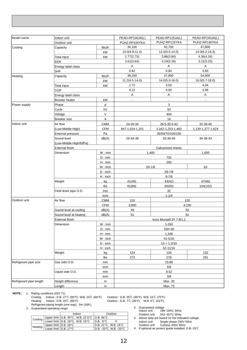
Model name Indoor unit PEAD-RP100JA(L) PEAD-RP125JA(L) PEAD-RP140JA(L)Outdoor unit PUHZ-RP100YKA PUHZ-RP125YKA PUHZ-RP140YKA
Cooling Capacity Btu/hkW
Total input kWEEREnergy label classSHF
Heating Capacity Btu/hkW
Total input kWCOPEnergy label classBooster heater kW - - -
Power supply Phase 3Cycle Hz 50Voltage V 400Breaker size A 16
Indoor unit
Outdoor unit
Weight kg 124 132lbs 273
126278 291
Refrigerant pipe size Gas side O.D. mm 15.88inch 5/8
Liquid side O.D. mm 9.52inch 3/8
Refrigerant pipe length Height difference m Max. 30Length m Max. 75
34,100 42,700 47,80010.0(4.9-11.4) 12.5(5.5-14.0) 14.0(6.2-15.3)
2.77(2.75) 3.86(3.84) 4.36(4.34)3.61(3.64) 3.24(3.26) 3.21(3.23)
A A A0.82 0.84 0.83
38,200 47,800 54,60011.2(4.5-14.0) 14.0(5.0-16.0) 16.0(5.7-18.0)
2.72 3.50 4.044.12 4.00 3.96
A A A
Air flow CMM 24-29-34 32-39-46(Low-Middle-High) CFM 847-1,024-1,201
29.5-35.5-421,042-1,253-1,483 1,130-1,377-1,624
External pressure Pa 35/50/70/100/150Sound level dB(A) 29-34-38 33-36-40 34-38-43(Low-Middle-High/50Pa)External finish Galvanized sheetsDimension W : mm 1,400 1,600
D : mm 732H : mm 250W : inch 55-1/8 63D : inch 28-7/8H : inch 9-7/8
Weight kg 41(40) 47(46)lbs 91(89) 104(102)
43(42)95(93)
mminch 1-1/4
Field drain pipe O.D. 32
Air flow CMM 120CFM 4,230
1103,880
Sound level at cooling dB(A) 49 50Sound level at heating dB(A) 51 52External finish Ivory Munsell 3Y 7.8/1.1Dimension W : mm 1,050
D : mm 330+30H : mm 1,338W : inch 41-5/16D : inch 13 + 1-3/16H : inch 52-11/16
13
NOTE: 1. Rating conditions (ISO T1)Cooling Indoor : D.B. 27 (80°F) W.B. 19 (66°F) Outdoor : D.B. 35 (95°F) W.B. 24 (75°F)Heating Indoor : D.B. 20 (68°F) Outdoor : D.B. 7 (45°F) W.B. 6 (43°F)Refrigerant piping length (one way) : 5m (16ft.)
2. Guaranteed operating range
Indoor Outdoor
Cooling Upper limit D.B. 35°C, W.B. 22.5°C D.B. 46°CLower limit D.B. 19°C, W.B. 15°C D.B. -5°C 1
Heating Upper limit D.B. 28°C D.B. 21°C, W.B. 15°CLower limit D.B. 17°C D.B. -20°C, W.B. -20°C
4. Above data are based on the indicated voltage.
1. If optional air protect guide is installed : D.B.-15
Indoor unit 3 phase 400V 50Hz3 phase 400V 50HzOutdoor unit
3. Guaranteed voltage 342~457V, 50Hz
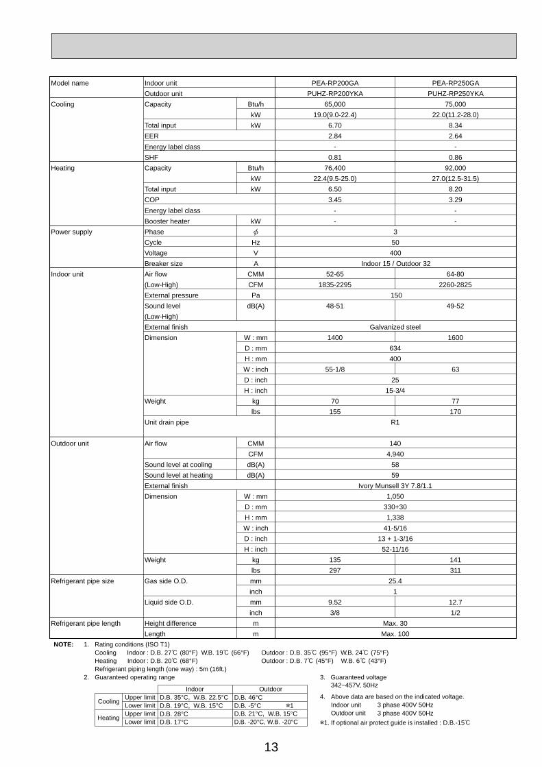
Model name Indoor unit PEA-RP200GA PEA-RP250GAOutdoor unit PUHZ-RP200YKA PUHZ-RP250YKA
Cooling Capacity Btu/h 65,000 75,000kW 19.0(9.0-22.4) 22.0(11.2-28.0)
Total input kW 6.70 8.34EEREnergy label class
2.84 2.64- -
SHF 0.81 0.86Heating Capacity Btu/h 76,400 92,000
kW 22.4(9.5-25.0) 27.0(12.5-31.5)Total input kW 6.50 8.20COP 3.45 3.29Energy label class - -Booster heater kW - -
Power supply Phase 3Cycle Hz 50Voltage V 400Breaker size A Indoor 15 / Outdoor 32
Indoor unit Air flow CMM 52-65 64-80(Low-High) CFM 1835-2295 2260-2825External pressure Pa 150Sound level dB(A) 48-51 49-52(Low-High)External finish Galvanized steelDimension W : mm 16001400
D : mm 634H : mm 400W : inch 6355-1/8D : inch 25H : inch 15-3/4
Weight kg 70 77lbs 155 170
Unit drain pipe R1
Outdoor unit Air flow CMM 140CFM 4,940
Sound level at cooling dB(A) 58Sound level at heating dB(A) 59External finish Ivory Munsell 3Y 7.8/1.1Dimension W : mm 1,050
D : mm 330+30H : mm 1,338W : inch 41-5/16D : inch 13 + 1-3/16H : inch 52-11/16
Weight kg 135lbs 297
141311
Refrigerant pipe size Gas side O.D. mm 25.4inch 1
Liquid side O.D. mm 12.7inch 1/2
9.523/8
Refrigerant pipe length Height difference m Max. 30Length m Max. 100

14
NOTE: 1. Rating conditions (ISO T1)Cooling Indoor : D.B. 27 (80°F) W.B. 19 (66°F) Outdoor : D.B. 35 (95°F) W.B. 24 (75°F)Heating Indoor : D.B. 20 (68°F) Outdoor : D.B. 7 (45°F) W.B. 6 (43°F)Refrigerant piping length (one way) : 5m (16ft.)
2. Guaranteed operating range
Indoor Outdoor
Cooling Upper limit D.B. 35°C, W.B. 22.5°C D.B. 46°CLower limit D.B. 19°C, W.B. 15°C D.B. -5°C 1
Heating Upper limit D.B. 28°C D.B. 21°C, W.B. 15°CLower limit D.B. 17°C D.B. -20°C, W.B. -20°C
4. Above data are based on the indicated voltage.
1. If optional air protect guide is installed : D.B.-15
Indoor unit 3 phase 400V 50Hz3 phase 400V 50HzOutdoor unit
3. Guaranteed voltage 342~457V, 50Hz
Model name Indoor unit PEA-RP400GA PEA-RP500GAOutdoor unit PUHZ-RP200YKA 2 PUHZ-RP250YKA 2
Cooling Capacity Btu/h 130,000 150,000kW 38.0(18.0-44.8) 44.0(22.4-56.0)
Total input kW 12.95 17.16EER 2.93 2.56Energy label class - -
Energy label class - -
SHF 0.75 0.77Heating Capacity Btu/h 153,000 184,000
kW 44.8(18.0-50.0) 54.0(25.0-63.0)Total input kW 12.55 16.88COP 3.57 3.20
Booster heater kW - -Power supply Phase 3
Cycle Hz 50Voltage V 400Breaker size A Indoor 15 / Outdoor 32 2
Indoor unit Air flow CMM 120 160(High) CFM 4240 5650External pressure Pa 150Sound level dB(A) 52 53(High)External finish Galvanized steelDimension W : mm 1,947
D : mm 764H : mm 595W : inch 79-11/16D : inch 30-1/8H : inch 23-7/16
Weight kg 130 133lbs 286 293
Unit drain pipe R1
Outdoor unit(Per 1 outdoor unit)
Air flow CMMCFM
Sound level at cooling dB(A)Sound level at heating dB(A)External finishDimension W : mm
D : mmH : mmW : inchD : inchH : inch
Weight kglbs
Refrigerant pipe size Gas side O.D. mm 25.4 2inch 1 2
Liquid side O.D. mm 12.7 2inch 1/2 2
9.52 23/8 2
Refrigerant pipe length Height difference m Max. 30Length m Max. 100 (per 1 outdoor unit)
1404,940
5859
Ivory Munsell 3Y 7.8/1.11,050
330+301,338
41-5/1613 + 1-3/16
52-11/16135297
141311
15
NOTE: 1. Rating conditions (ISO T1)Cooling Indoor : D.B. 27 (80°F) W.B. 19 (66°F) Outdoor : D.B. 35 (95°F) W.B. 24 (75°F)Heating Indoor : D.B. 20 (68°F) Outdoor : D.B. 7 (45°F) W.B. 6 (43°F)Refrigerant piping length (one way) : 5m (16ft.)
2. Guaranteed operating range
Indoor Outdoor
Cooling Upper limit D.B. 35°C, W.B. 22.5°C D.B. 46°CLower limit D.B. 19°C, W.B. 15°C D.B. -5°C
Heating Upper limit D.B. 28°C D.B. 21°C, W.B. 15°CLower limit D.B. 17°C D.B. -11°C, W.B. -12°C
4. Above data are based on the indicated voltage.
If optional air protect guide installed. D.B.-15
Indoor unit Single phase 230V 50HzSingle phase 230V 50HzOutdoor unit
3. Guaranteed voltage 198~264V, 50Hz
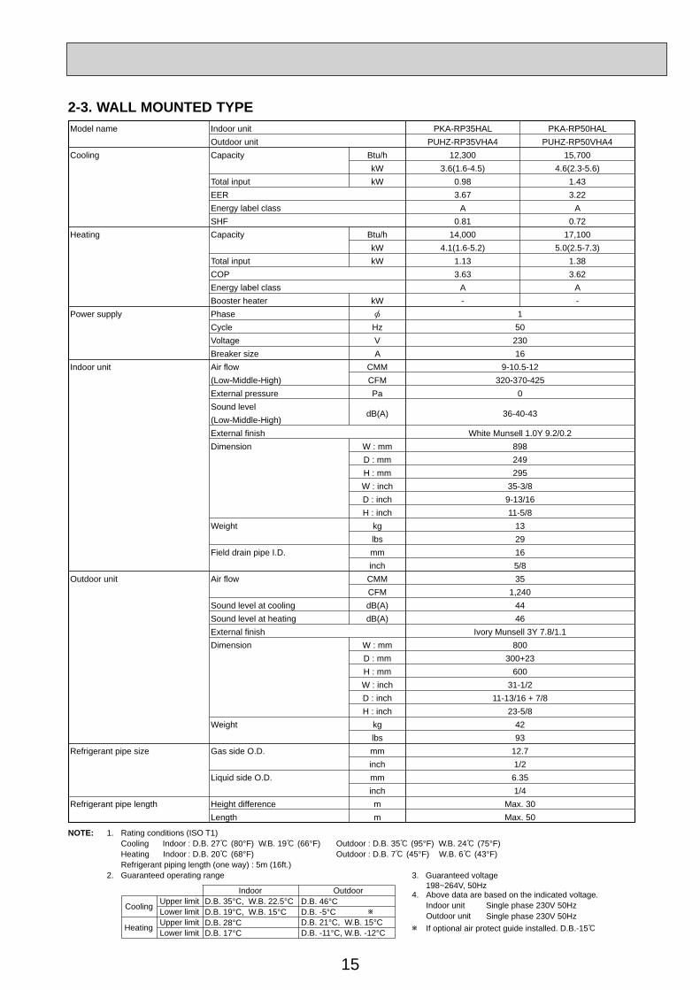
Model name Indoor unit PKA-RP35HAL PKA-RP50HALOutdoor unit PUHZ-RP35VHA4 PUHZ-RP50VHA4
Cooling Capacity Btu/h 12,300 15,700kW 3.6(1.6-4.5) 4.6(2.3-5.6)
Total input kW 0.98 1.43EER 3.67 3.22Energy label class A ASHF 0.81 0.72
Heating Capacity Btu/h 14,000 17,100kW 4.1(1.6-5.2) 5.0(2.5-7.3)
Total input kW 1.13 1.38COP 3.63 3.62Energy label class A ABooster heater kW - -
Power supply Phase 1Cycle Hz 50Voltage V 230Breaker size A 16
Indoor unit Air flow CMM 9-10.5-12(Low-Middle-High) CFM 320-370-425External pressure Pa 0Sound level
dB(A) 36-40-43(Low-Middle-High)External finish White Munsell 1.0Y 9.2/0.2Dimension W : mm 898
D : mm 249H : mm 295W : inch 35-3/8D : inch 9-13/16H : inch 11-5/8
Weight kg 13lbs 29
Field drain pipe I.D. mm 16inch 5/8
Outdoor unit Air flow CMM 35CFM 1,240
Sound level at cooling dB(A) 44Sound level at heating dB(A) 46External finish Ivory Munsell 3Y 7.8/1.1Dimension W : mm 800
D : mm 300+23H : mm 600W : inch 31-1/2D : inch 11-13/16 + 7/8H : inch 23-5/8
Weight kg 42lbs 93
Refrigerant pipe size Gas side O.D. mm 12.7inch 1/2
Liquid side O.D. mm 6.35inch 1/4
Refrigerant pipe length Height difference m Max. 30Length m Max. 50
2-3. WALL MOUNTED TYPE
16
NOTE: 1. Rating conditions (ISO T1)Cooling Indoor : D.B. 27 (80°F) W.B. 19 (66°F) Outdoor : D.B. 35 (95°F) W.B. 24 (75°F)Heating Indoor : D.B. 20 (68°F) Outdoor : D.B. 7 (45°F) W.B. 6 (43°F)Refrigerant piping length (one way) : 5m (16ft.)
2. Guaranteed operating range
Indoor Outdoor
Cooling Upper limit D.B. 35°C, W.B. 22.5°C D.B. 46°CLower limit D.B. 19°C, W.B. 15°C D.B. -5°C
Heating Upper limit D.B. 28°C D.B. 21°C, W.B. 15°CLower limit D.B. 17°C D.B. -20°C, W.B. -20°C
4. Above data are based on the indicated voltage.
If optional air protect guide installed. D.B.-15
Indoor unit Single phase 230V 50HzV: Single phase 230V 50HzY: 3phase 400V 50Hz
Outdoor unit
3. Guaranteed voltage 198~264V, 50Hz (RP100Y: 342~457V, 50Hz)
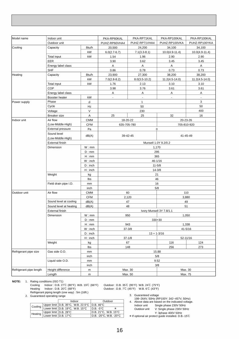
Model name Indoor unit PKA-RP71KAL PKA-RP100KAL PKA-RP100KALOutdoor unit PUHZ-RP71VHA4 PUHZ-RP100VKA PUHZ-RP100YKA
Cooling Capacity Btu/h 24,200 34,100 34,100kW 7.1(3.3-8.1) 10.0(4.9-11.4) 10.0(4.9-11.4)
Total input kW 1.96 2.90 2.90EER 3.62 3.45 3.45Energy label class A A ASHF 0.78 0.73 0.73
Heating Capacity Btu/h 27,300 38,200 38,200kW 8.0(3.5-10.2) 11.2(4.5-14.0) 11.2(4.5-14.0)
Total input kW 2.13 3.10 3.10COP 3.76 3.61 3.61Energy label class A A ABooster heater kW - - -
Power supply Phase 1Cycle Hz 50Voltage V 230Breaker size A 3225 16
Indoor unit Air flow CMM 18-20-22 20-23-26(Low-Middle-High) CFM 635-705-780 705-810-920
350400
External pressure Pa 0Sound level
dB(A) 39-42-45 41-45-49(Low-Middle-High)External finish Munsell 1.0Y 9.2/0.2Dimension W : mm 1,170
D : mm 295H : mm 365W : inch 46-1/16D : inch 11-5/8H : inch 14-3/8
Weight kg 21lbs 46
Field drain pipe I.D. mm 16inch 5/8
Outdoor unit Air flow CMM 60CFM 2,120
Sound level at cooling dB(A) 47Sound level at heating dB(A) 48
1103,880
4951
External finish Ivory Munsell 3Y 7.8/1.1Dimension W : mm 950
D : mm 330+301,050
H : mm 943 1,338W : inch 37-3/8D : inch
41-5/1613 + 1-3/16
H : inch 37-1/8 52-11/16Weight kg 67 116
lbs 148 256124273
Refrigerant pipe size Gas side O.D. mm 15.88inch 5/8
Liquid side O.D. mm 9.52inch 3/8
Refrigerant pipe length Height difference m Max. 30 Max. 30Length m Max. 50 Max. 75
PKA-RP60KALPUHZ-RP60VHA4
20,5006.0(2.7-6.7)
1.543.90
A0.86
23,9007.0(2.8-8.2)
1.763.98
A-
25
17
NOTE: 1. Rating conditions (ISO T1)Cooling Indoor : D.B. 27 (80°F) W.B. 19 (66°F) Outdoor : D.B. 35 (95°F) W.B. 24 (75°F)Heating Indoor : D.B. 20 (68°F) Outdoor : D.B. 7 (45°F) W.B. 6 (43°F)Refrigerant piping length (one way) : 5m (16ft.)
2. Guaranteed operating range
Indoor Outdoor
Cooling Upper limit D.B. 35°C, W.B. 22.5°C D.B. 46°CLower limit D.B. 19°C, W.B. 15°C D.B. -5°C 1
Heating Upper limit D.B. 28°C D.B. 21°C, W.B. 15°CLower limit D.B. 17°C D.B. -11°C, W.B. -12°C 2
4. Above data are based on the indicated voltage.
1. If optional air protect guide installed. D.B.-15°C 2. For RP60/71 D.B. -20°C, W.B. -20°C
Indoor unit Single phase 230V 50HzSingle phase 230V 50HzOutdoor unit
3. Guaranteed voltage 198~264V, 50Hz
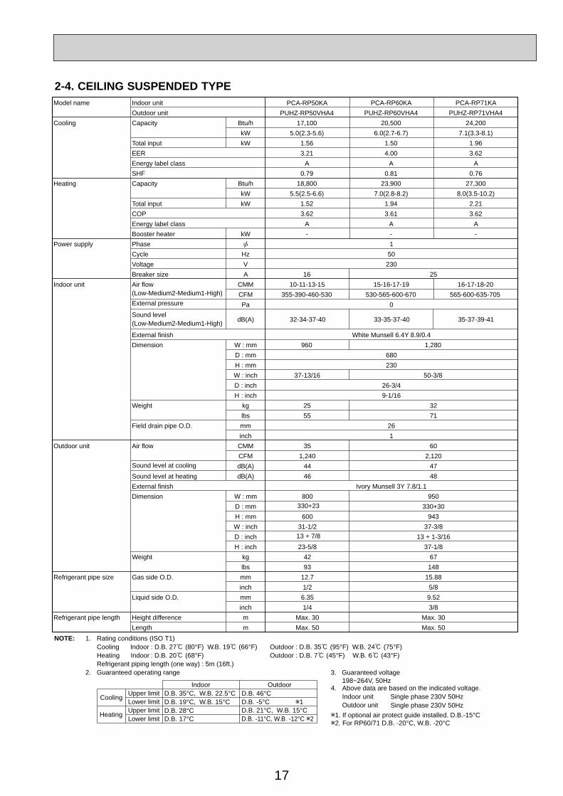
Model name Indoor unit PCA-RP60KA PCA-RP71KAOutdoor unit PUHZ-RP60VHA4 PUHZ-RP71VHA4
Cooling Capacity Btu/h 20,500 24,200kW 6.0(2.7-6.7) 7.1(3.3-8.1)
Total input kW 1.50 1.96EER 4.00 3.62Energy label class A ASHF 0.81 0.76
Heating Capacity Btu/h 23,900 27,300kW 7.0(2.8-8.2) 8.0(3.5-10.2)
Total input kW 1.94 2.21COP 3.61 3.62Energy label class A ABooster heater kW - -
Power supply Phase 1Cycle Hz 50Voltage V 230Breaker size A 16 25
Indoor unit Air flow CMM 10-11-13-15 15-16-17-19 16-17-18-20(Low-Medium2-Medium1-High) CFM 355-390-460-530 530-565-600-670 565-600-635-705External pressure Pa 0Sound level
dB(A) 32-34-37-40 33-35-37-40 35-37-39-41(Low-Medium2-Medium1-High)
External finish White Munsell 6.4Y 8.9/0.4Dimension W : mm 1,280960
D : mm 680H : mm 230W : inch 50-3/837-13/16D : inch 26-3/4H : inch 9-1/16
Weight kg 32lbs 71
2555
Field drain pipe O.D. mm 26inch 1
Outdoor unit Air flow CMM 35 60CFM 1,240 2,120
Sound level at cooling dB(A) 44 47Sound level at heating dB(A) 46 48External finish Ivory Munsell 3Y 7.8/1.1Dimension W : mm 800 950
D : mm 330+23 330+30H : mm 600 943W : inch 31-1/2 37-3/8D : inch 13 + 7/8 13 + 1-3/16H : inch 23-5/8 37-1/8
Weight kg 42 67lbs 93 148
Refrigerant pipe size Gas side O.D. mm 12.7 15.88inch 1/2 5/8
Liquid side O.D. mm 6.35 9.52inch 1/4 3/8
Refrigerant pipe length Height difference m Max. 30 Max. 30Length m Max. 50 Max. 50
PCA-RP50KAPUHZ-RP50VHA4
17,1005.0(2.3-5.6)
1.563.21
A0.79
18,8005.5(2.5-6.6)
1.523.62
A-
2-4. CEILING SUSPENDED TYPE
18
NOTE: 1. Rating conditions (ISO T1)Cooling Indoor : D.B. 27 (80°F) W.B. 19 (66°F) Outdoor : D.B. 35 (95°F) W.B. 24 (75°F)Heating Indoor : D.B. 20 (68°F) Outdoor : D.B. 7 (45°F) W.B. 6 (43°F)Refrigerant piping length (one way) : 5m (16ft.)
2. Guaranteed operating range
Indoor Outdoor
Cooling Upper limit D.B. 35°C, W.B. 22.5°C D.B. 46Lower limit D.B. 19°C, W.B. 15°C D.B. -5
Heating Upper limit D.B. 28°C D.B. 21 , W.B. 15Lower limit D.B. 17°C D.B. -20 , W.B. -20
4. Above data are based on the indicated voltage.
If optional air protect guide installed. D.B.-15
Indoor unit Single phase 230V 50HzSingle phase 230V 50HzOutdoor unit
3. Guaranteed voltage 198~264V, 50Hz
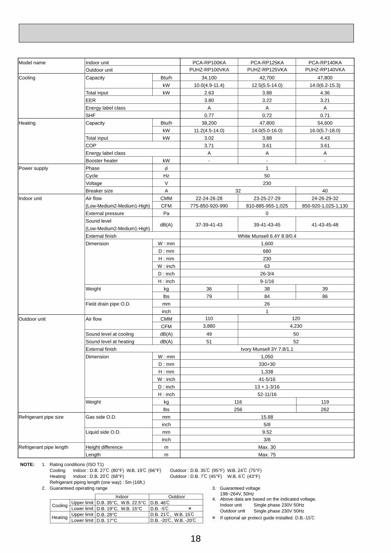
Model name Indoor unit PCA-RP100KA PCA-RP125KA PCA-RP140KAOutdoor unit PUHZ-RP100VKA PUHZ-RP125VKA PUHZ-RP140VKA
Cooling Capacity Btu/h 34,100 42,700 47,800kW 10.0(4.9-11.4) 12.5(5.5-14.0) 14.0(6.2-15.3)
Total input kW 2.63 3.88 4.36EER 3.80 3.22 3.21Energy label class A A ASHF 0.77 0.72 0.71
Heating Capacity Btu/h 38,200 47,800 54,600kW 11.2(4.5-14.0) 14.0(5.0-16.0) 16.0(5.7-18.0)
Total input kW 3.02 3.88 4.43COP 3.71 3.61 3.61Energy label class A A ABooster heater kW - - -
Power supply Phase 1Cycle Hz 50Voltage V 230Breaker size A 32 40
Indoor unit Air flow CMM 22-24-26-28 23-25-27-29(Low-Medium2-Medium1-High) CFM 775-850-920-990 810-885-955-1,025
24-26-29-32850-920-1,025-1,130
External pressure Pa 0Sound level
dB(A) 37-39-41-43 39-41-43-45 41-43-45-48(Low-Medium2-Medium1-High)External finish White Munsell 6.4Y 8.9/0.4Dimension W : mm 1,600
D : mm 680H : mm 230W : inch 63D : inch 26-3/4H : inch 9-1/16
Weight kg 36 38 39lbs 79 84 86
Field drain pipe O.D. mm 26inch 1
Outdoor unit Air flow CMMCFM
Sound level at cooling dB(A) 49 50Sound level at heating dB(A) 51 52
110 1203,880 4,230
External finish Ivory Munsell 3Y 7.8/1.1Dimension W : mm 1,050
D : mm 330+30H : mm 1,338W : inch 41-5/16D : inch 13 + 1-3/16H : inch 52-11/16
Weight kg 116 119lbs 256 262
Refrigerant pipe size Gas side O.D. mm 15.88inch 5/8
Liquid side O.D. mm 9.52inch 3/8
Refrigerant pipe length Height difference m Max. 30Length m Max. 75
19
NOTE: 1. Rating conditions (ISO T1)Cooling Indoor : D.B. 27 (80°F) W.B. 19 (66°F) Outdoor : D.B. 35 (95°F) W.B. 24 (75°F)Heating Indoor : D.B. 20 (68°F) Outdoor : D.B. 7 (45°F) W.B. 6 (43°F)Refrigerant piping length (one way) : 5m (16ft.)
2. Guaranteed operating range
Indoor Outdoor
Cooling Upper limit D.B. 35°C, W.B. 22.5°C D.B. 46°CLower limit D.B. 19°C, W.B. 15°C D.B. -5°C
Heating Upper limit D.B. 28°C D.B. 21°C, W.B. 15°CLower limit D.B. 17°C D.B. -20°C, W.B. -20°C
4. Above data are based on the indicated voltage.Indoor unit Single phase 230V 50Hz
3 phase 400V 50HzOutdoor unit
Indoor unit 198~264V, 50Hz342~457V, 50HzOutdoor unit
3. Guaranteed voltage
If optional air protect guide installed. D.B.-15
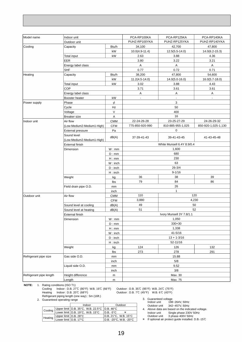
Model name Indoor unit PCA-RP100KA PCA-RP125KA PCA-RP140KAOutdoor unit PUHZ-RP100YKA PUHZ-RP125YKA PUHZ-RP140YKA
Cooling Capacity Btu/hkW
Total input kWEEREnergy label classSHF
Heating Capacity Btu/hkW
Total input kWCOPEnergy label classBooster heater kW
Power supply Phase 3Cycle Hz 50Voltage V 400
16Breaker size AIndoor unit Air flow CMM
(Low-Medium2-Medium1-High) CFMExternal pressure PaSound level dB(A)(Low-Medium2-Medium1-High)External finishDimension W : mm
D : mmH : mmW : inchD : inchH : inch
Weight kglbs
Field drain pipe O.D. mminch
Outdoor unit Air flow CMMCFM
Sound level at cooling dB(A)Sound level at heating dB(A)External finishDimension W : mm
D : mmH : mmW : inchD : inchH : inch
Weight kg 124 132lbs 273
126278 291
Refrigerant pipe size Gas side O.D. mm 15.88inch 5/8
Liquid side O.D. mm 9.52inch 3/8
Refrigerant pipe length Height difference m Max. 30Length m Max. 75
34,100 42,700 47,80010.0(4.9-11.4) 12.5(5.5-14.0) 14.0(6.2-15.3)
2.63 3.88 4.363.80 3.22 3.21
A A A0.77 0.72 0.71
38,200 47,800 54,60011.2(4.5-14.0) 14.0(5.0-16.0) 16.0(5.7-18.0)
3.02 3.88 4.433.71 3.61 3.61
A A A- - -
22-24-26-28 23-25-27-29775-850-920-990 810-885-955-1,025
24-26-29-32850-920-1,025-1,130
0
37-39-41-43 39-41-43-45 41-43-45-48
White Munsell 6.4Y 8.9/0.41,60068023063
26-3/49-1/16
36 38 3979 84 86
261
49 5051 52
110 1203,880 4,230
Ivory Munsell 3Y 7.8/1.11,050
330+301,338
41-5/1613 + 1-3/16
52-11/16

20
Model name Indoor unit PCA-RP71HA PCA-RP125HA PCA-RP125HAOutdoor unit PUHZ-RP71VHA4 PUHZ-RP125VKA PUHZ-RP125YKA
Cooling Capacity Btu/h 24,200 42,700 42,700kW 7.1(3.3-8.1) 12.5(5.5-14.0) 12.5(5.5-14.0)
Total input kW 2.21 3.88 3.88EER 3.21 3.22 3.22Energy label class A A ASHF 0.74 0.77 0.77
Heating Capacity Btu/h 25,900 47,100 47,100kW 7.6(3.5-10.2) 13.8(5.0-16.0) 13.8(5.0-16.0)
Total input kW 2.23 4.05 4.05COP 3.41 3.41 3.41Energy label class B B BBooster heater kW - - -
Power supply Phase 1 3Cycle Hz 50 50Voltage V 230 400Breaker size A 25 16
Indoor unit Air flow CMM 17-19 30-38(Low-High) CFM 600-670 1,060-1,350External pressure Pa 0Sound level dB(A) 34-38 44-50(Low-High)External finish Stainless steelDimension W : mm 1136 1520
D : mm 650H : mm 280W : inch 44-3/4 59-7/8D : inch 25-5/8H : inch 11
Weight kg 41 56lbs 90 124
Field drain pipe O.D. mm 26inch 1
Outdoor unit Air flow CMM 60 120CFM 2,120 4,230
Sound level at cooling dB(A) 47 50Sound level at heating dB(A) 48 52External finish Ivory Munsell 3Y 7.8/1.1Dimension W : mm 950 1,050
D : mm 330+30 330+30H : mm 943 1,338W : inch 37-3/8 41-5/16D : inch 13 + 1-3/16 13 + 1-3/16H : inch 37-1/8 52-11/16
Weight kg 67 116 126lbs 148 256 278
Refrigerant pipe size Gas side O.D. mm 15.88 15.88inch 5/8 5/8
Liquid side O.D. mm 9.52 9.52inch 3/8 3/8
Refrigerant pipe length Height difference m Max. 30 Max. 30Length m Max. 50 Max. 75
NOTE: 1. Rating conditions (ISO T1)Cooling Indoor : D.B. 27 (80°F) W.B. 19 (66°F) Outdoor : D.B. 35 (95°F) W.B. 24 (75°F)Heating Indoor : D.B. 20 (68°F) Outdoor : D.B. 7 (45°F) W.B. 6 (43°F)Refrigerant piping length (one way) : 5m (16ft.)
2. Guaranteed operating range
Indoor Outdoor
Cooling Upper limit D.B. 35°C, W.B. 22.5°C D.B. 46°CLower limit D.B. 19°C, W.B. 15°C D.B. -5°C
Heating Upper limit D.B. 28°C D.B. 21°C, W.B. 15°CLower limit D.B. 17°C D.B. -20°C, W.B. -20°C
4. Above data are based on the indicated voltage.
If optional air protect guide installed. D.B.-15
Indoor unit Single phase 230V 50HzV: Single phase 230V 50Hz,Y: 3 phase 400V 50Hz
Outdoor unit
3. Guaranteed voltage 198~264V, 50Hz (RP125Y : 342~457V, 50Hz)
21
NOTE: 1. Rating conditions (ISO T1)Cooling Indoor : D.B. 27 (80°F) W.B. 19 (66°F) Outdoor : D.B. 35 (95°F) W.B. 24 (75°F)Heating Indoor : D.B. 20 (68°F) Outdoor : D.B. 7 (45°F) W.B. 6 (43°F)Refrigerant piping length (one way) : 5m (16ft.)
2. Guaranteed operating range
Indoor Outdoor
Cooling Upper limit D.B. 35°C, W.B. 22.5°C D.B. 46°CLower limit D.B. 19°C, W.B. 15°C D.B. -5°C
Heating Upper limit D.B. 28°C D.B. 21°C, W.B. 15°CLower limit D.B. 17°C D.B. -20°C, W.B. -20°C
4. Above data are based on the indicated voltage.
If optional air protect guide installed. D.B.-15
Indoor unit Single phase 230V 50HzSingle phase 230V 50HzOutdoor unit
3. Guaranteed voltage 198~264V, 50Hz
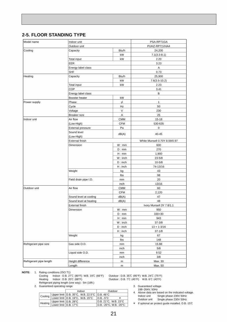
Model name Indoor unit PSA-RP71GAOutdoor unit PUHZ-RP71VHA4
Cooling Capacity Btu/h 24,200kW 7.1(3.3-8.1)
Total input kW 2.20EER 3.23Energy label class ASHF 0.73
Heating Capacity Btu/h 25,900kW 7.6(3.5-10.2)
Total input kW 2.23COP 3.41Energy label class BBooster heater kW -
Power supply Phase 1Cycle Hz 50Voltage V 230Breaker size A 25
Indoor unit Air flow CMM 15-18(Low-High) CFM 530-635External pressure Pa 0Sound level dB(A) 40-45(Low-High)External finish White Munsell 0.70Y 8.59/0.97Dimension W : mm 600
D : mm 270H : mm 1,900W : inch 23-5/8D : inch 10-5/8H : inch 74-13/16
Weight kg 43lbs 98
Field drain pipe I.D. mm 20inch 13/16
Outdoor unit Air flow CMM 60CFM 2,120
Sound level at cooling dB(A) 47Sound level at heating dB(A) 48External finish Ivory Munsell 3Y 7.8/1.1Dimension W : mm 950
D : mm 330+30H : mm 943W : inch 37-3/8D : inch 13 + 1-3/16H : inch 37-1/8
Weight kg 67lbs 148
Refrigerant pipe size Gas side O.D. mm 15.88inch 5/8
Liquid side O.D. mm 9.52inch 3/8
Refrigerant pipe length Height difference m Max. 30Length m Max. 50
2-5. FLOOR STANDING TYPE

22
NOTE: 1. Rating conditions (ISO T1)Cooling Indoor : D.B. 27 (80°F) W.B. 19 (66°F) Outdoor : D.B. 35 (95°F) W.B. 24 (75°F)Heating Indoor : D.B. 20 (68°F) Outdoor : D.B. 7 (45°F) W.B. 6 (43°F)Refrigerant piping length (one way) : 5m (16ft.)
2. Guaranteed operating range
Indoor Outdoor
Cooling Upper limit D.B. 35°C, W.B. 22.5°C D.B. 46Lower limit D.B. 19°C, W.B. 15°C D.B. -5
Heating Upper limit D.B. 28°C D.B. 21 , W.B. 15Lower limit D.B. 17°C D.B. -20 , W.B. -20
4. Above data are based on the indicated voltage.
If optional air protect guide installed. D.B.-15
Indoor unit Single phase 230V 50HzSingle phase 230V 50HzOutdoor unit
3. Guaranteed voltage 198~264V, 50Hz
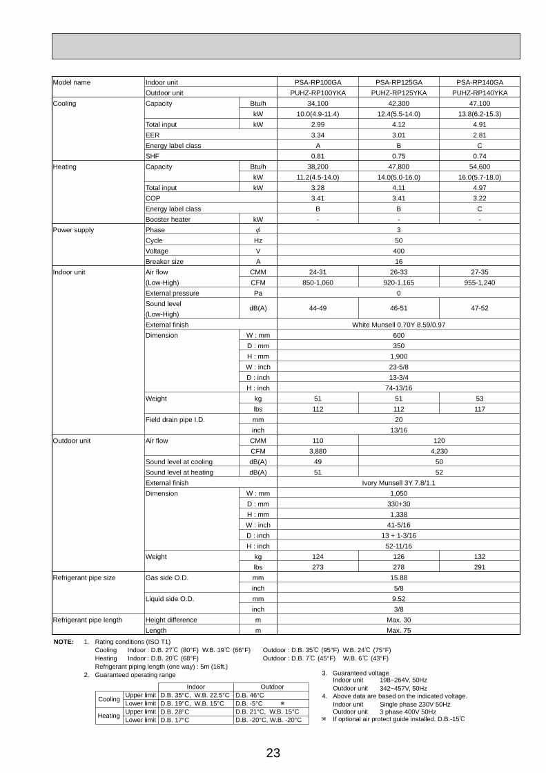
Model name Indoor unit PSA-RP100GA PSA-RP125GA PSA-RP140GAOutdoor unit PUHZ-RP100VKA PUHZ-RP125VKA PUHZ-RP140VKA
Cooling Capacity Btu/h 34,100 42,300 47,100kW 10.0(4.9-11.4) 12.4(5.5-14.0) 13.8(6.2-15.3)
Total input kW 2.99 4.12 4.91EER 3.34 3.01 2.81Energy label class A B CSHF 0.81 0.75 0.74
Heating Capacity Btu/h 38,200 47,800 54,600kW 11.2(4.5-14.0) 14.0(5.0-16.0) 16.0(5.7-18.0)
Total input kW 3.28 4.11 4.97COP 3.41 3.41 3.22Energy label class B B CBooster heater kW - - -
Power supply Phase 1Cycle Hz 50Voltage V 230Breaker size A 32 40
Indoor unit Air flow CMM 24-31 26-33 27-35(Low-High) CFM 850-1060 920-1165 955-1240External pressure Pa 0Sound level
dB(A) 44-49 46-51 47-52(Low-High)External finish White Munsell 0.70Y 8.59/0.97Dimension W : mm 600
D : mm 350H : mm 1,900W : inch 23-5/8D : inch 13-3/4H : inch 74-13/16
Weight kg 51 53lbs 112 117
Field drain pipe I.D. mm 20inch 13/16
Outdoor unit Air flow CMMCFM
Sound level at cooling dB(A) 49 50Sound level at heating dB(A) 51 52
110 1203,880 4,230
External finish Ivory Munsell 3Y 7.8/1.1Dimension W : mm 1,050
D : mm 330+30H : mm 1,338W : inch 41-5/16D : inch 13 + 1-3/16H : inch 52-11/16
Weight kg 116lbs 256
119262
Refrigerant pipe size Gas side O.D. mm 15.88inch 5/8
Liquid side O.D. mm 9.52inch 3/8
Refrigerant pipe length Height difference m Max. 30Length m Max. 75
23
NOTE: 1. Rating conditions (ISO T1)Cooling Indoor : D.B. 27 (80°F) W.B. 19 (66°F) Outdoor : D.B. 35 (95°F) W.B. 24 (75°F)Heating Indoor : D.B. 20 (68°F) Outdoor : D.B. 7 (45°F) W.B. 6 (43°F)Refrigerant piping length (one way) : 5m (16ft.)
2. Guaranteed operating range
Indoor Outdoor
Cooling Upper limit D.B. 35°C, W.B. 22.5°C D.B. 46°CLower limit D.B. 19°C, W.B. 15°C D.B. -5°C
Heating Upper limit D.B. 28°C D.B. 21°C, W.B. 15°CLower limit D.B. 17°C D.B. -20°C, W.B. -20°C
4. Above data are based on the indicated voltage.Indoor unit Single phase 230V 50Hz
3 phase 400V 50HzOutdoor unit
Indoor unit 198~264V, 50Hz342~457V, 50HzOutdoor unit
3. Guaranteed voltage
If optional air protect guide installed. D.B.-15
Model name Indoor unit PSA-RP100GA PSA-RP125GA PSA-RP140GAOutdoor unit PUHZ-RP100YKA PUHZ-RP125YKA PUHZ-RP140YKA
Cooling Capacity Btu/h 34,100 42,300 47,100kW 10.0(4.9-11.4) 12.4(5.5-14.0) 13.8(6.2-15.3)
Total input kW 2.99 4.12 4.91EER 3.34 3.01 2.81Energy label class A B CSHF 0.81 0.75 0.74
Heating Capacity Btu/h 38,200 47,800 54,600kW 11.2(4.5-14.0) 14.0(5.0-16.0) 16.0(5.7-18.0)
Total input kW 3.28 4.11 4.97COP 3.41 3.41 3.22Energy label class B B CBooster heater kW - - -
Power supply Phase 3Cycle Hz 50Voltage V 400Breaker size A 16
Indoor unit Air flow CMM 24-31 26-33 27-35(Low-High) CFM 850-1,060 920-1,165 955-1,240External pressure Pa 0Sound level dB(A) 44-49 46-51 47-52(Low-High)External finish White Munsell 0.70Y 8.59/0.97Dimension W : mm 600
D : mm 350H : mm 1,900W : inch 23-5/8D : inch 13-3/4H : inch 74-13/16
Weight kg 51 51 53lbs 112 112 117
Field drain pipe I.D. mm 20inch 13/16
Outdoor unit Air flow CMMCFM
Sound level at cooling dB(A) 49 50Sound level at heating dB(A) 51 52
110 1203,880 4,230
External finish Ivory Munsell 3Y 7.8/1.1Dimension W : mm 1,050
D : mm 330+30H : mm 1,338W : inch 41-5/16D : inch 13 + 1-3/16H : inch 52-11/16
Weight kg 124 132lbs 273 291
126278
Refrigerant pipe size Gas side O.D. mm 15.88inch 5/8
Liquid side O.D. mm 9.52inch 3/8
Refrigerant pipe length Height difference m Max. 30Length m Max. 75
24
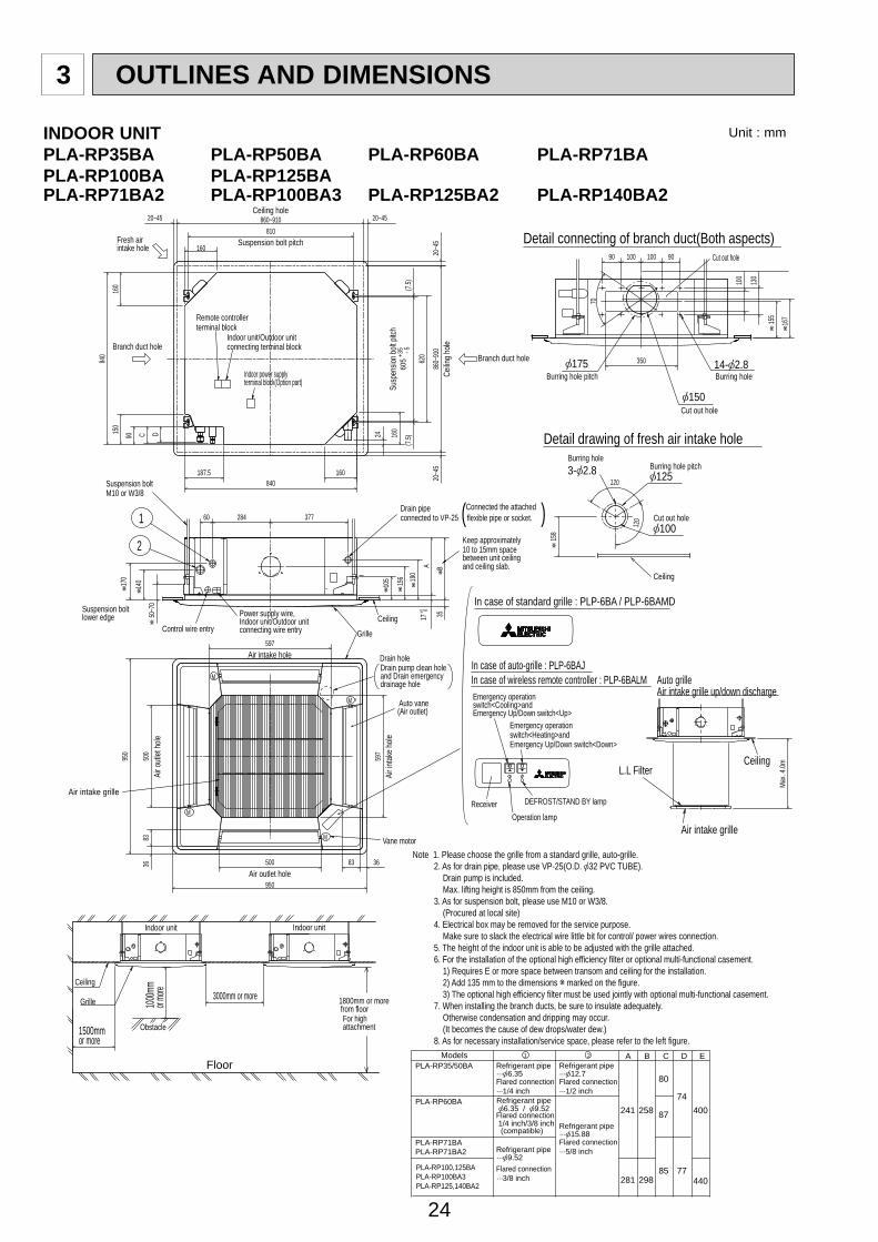
3 OUTLINES AND DIMENSIONS
Note 1. Please choose the grille from a standard grille, auto-grille. 2. As for drain pipe, please use VP-25(O.D. 32 PVC TUBE). Drain pump is included. Max. lifting height is 850mm from the ceiling. 3. As for suspension bolt, please use M10 or W3/8. (Procured at local site) 4. Electrical box may be removed for the service purpose. Make sure to slack the electrical wire little bit for control/ power wires connection. 5. The height of the indoor unit is able to be adjusted with the grille attached. 6. For the installation of the optional high efficiency filter or optional multi-functional casement. 1) Requires E or more space between transom and ceiling for the installation. 2) Add 135 mm to the dimensions marked on the figure. 3) The optional high efficiency filter must be used jointly with optional multi-functional casement. 7. When installing the branch ducts, be sure to insulate adequately. Otherwise condensation and dripping may occur. (It becomes the cause of dew drops/water dew.) 8. As for necessary installation/service space, please refer to the left figure.
Ceiling
Grille
Indoor unit
1500mmor more
1000m
mor m
ore 3000mm or more 1800mm or morefrom floorFor high attachment
Indoor unit
Obstacle
Floor
Ceiling
Air intake grille
Max.
4.0m
L.L Filter
37728460 ( )
Ceiling hole
Branch duct hole
Drain pipeconnected to VP-25
Ceiling
Grille
Drain hole
Models
Auto vane(Air outlet)
Air intake grille
Ceiling
Cut out hole
Cut out hole
Cut out hole
Burring hole pitch
Burring hole pitch Burring hole
Burring hole
Power supply wire,Indoor unit/Outdoor unit connecting wire entry
Indoor unit/Outdoor unit connecting terminal block
Indoor power supplyterminal block(Option part)
Control wire entry
Air intake hole
Air in
take h
ole
Air outlet hole
Air o
utlet
hole
Connected the attachedflexible pipe or socket.
Keep approximately 10 to 15mm spacebetween unit ceiling and ceiling slab.
Branch duct hole
Fresh air intake hole
Ceilin
g hole
Susp
ensio
n bolt
pitch
Suspension bolt pitch
Remote controller terminal block
Suspension bolt M10 or W3/8
(7.5)
(7.5)
605
+35
-
5
620
DEFROST/STAND BY lampReceiverOperation lamp
In case of standard grille : PLP-6BA / PLP-6BAMD
In case of wireless remote controller : PLP-6BALM Auto grilleAir intake grille up/down dischargeEmergency operation
switch<Cooling>andEmergency Up/Down switch<Up>
160
160
500
500
597
83 36
950
8336
950
597
A17
+5 0
B35
190
156
105
140
50~7
0
160
840
150
90 C D
840187.5
20~45 860~910 20~45
810
20~4
586
0~91
020
~45
24 160
M
M
M
M
120
120
175
125
167
158
Vane motor
2
1
Drain pump clean holeand Drain emergency drainage hole
130
100
70
155
350
90 100 100 90
BA C D E
241 258
80
87
74400
29885 77
440281
21
Refrigerant pipe··· 6.35Flared connection···1/4 inch
Refrigerant pipe··· 9.52Flared connection···3/8 inch
Refrigerant pipe··· 12.7Flared connection···1/2 inch
Refrigerant pipe··· 15.88Flared connection···5/8 inch
Refrigerant pipe6.35 / 9.52
Flared connection 1/4 inch/3/8 inch (compatible)
PLA-RP35/50BA
PLA-RP60BA
PLA-RP71BAPLA-RP71BA2
PLA-RP100,125BAPLA-RP100BA3PLA-RP125,140BA2
Detail drawing of fresh air intake hole
Detail connecting of branch duct(Both aspects)
3- 2.8
14- 2.8
150
100
Emergency operation switch<Heating>andEmergency Up/Down switch<Down>
In case of auto-grille : PLP-6BAJ
Suspension bolt lower edge
170
INDOOR UNITPLA-RP35BA PLA-RP50BA PLA-RP60BA PLA-RP71BAPLA-RP100BA PLA-RP125BAPLA-RP71BA2 PLA-RP100BA3 PLA-RP125BA2 PLA-RP140BA2
Unit : mm
25
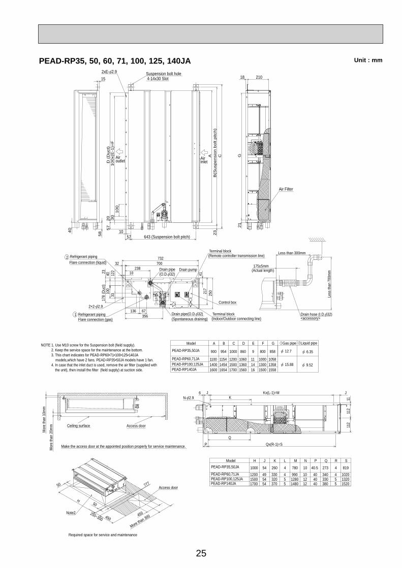
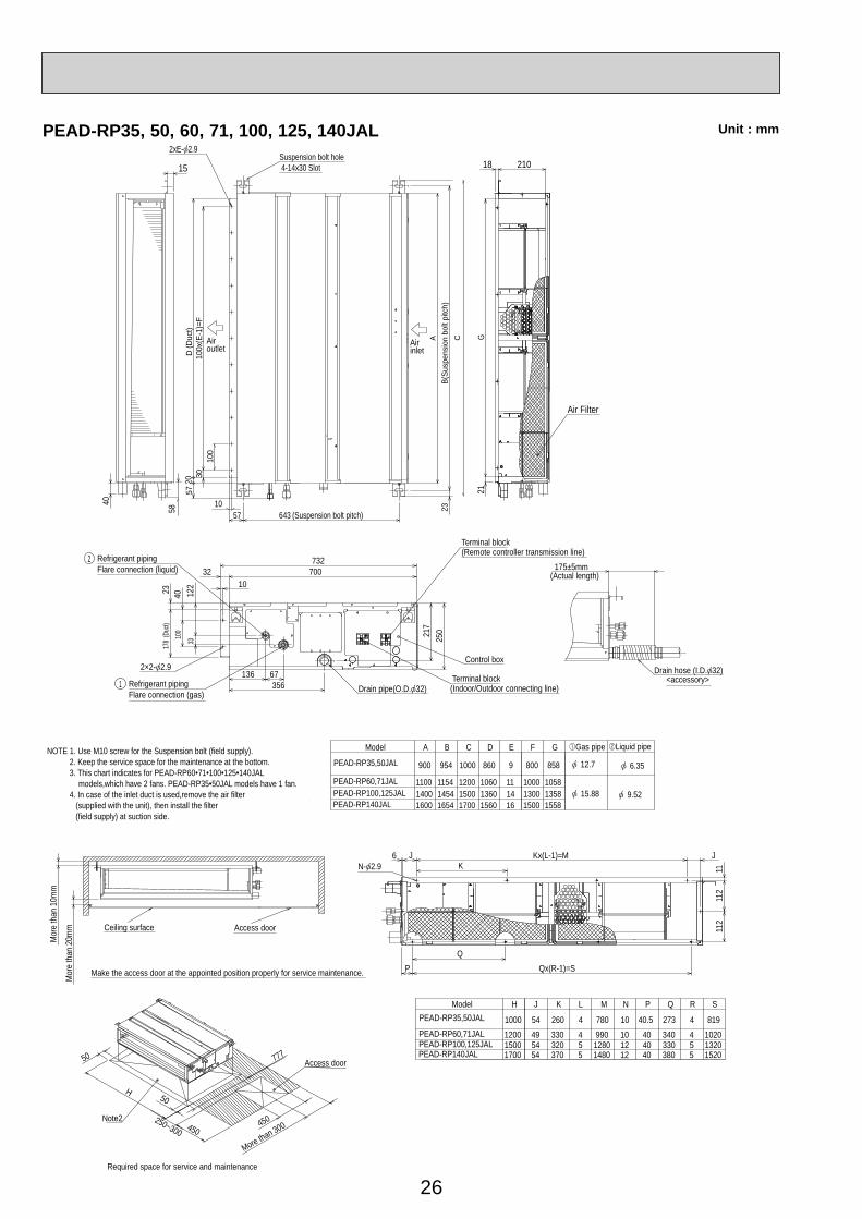
Unit : mmPEAD-RP35, 50, 60, 71, 100, 125, 140JA
Air Filter
Suspension bolt hole 4-14x30 Slot
Airoutlet Air
inlet
2xE- 2.9
2×2- 2.9
Refrigerant pipingFlare connection (liquid)
2
1 Refrigerant pipingFlare connection (gas)
Drain pump
Control box
Terminal block(Indoor/Outdoor connecting line)
Terminal block(Remote controller transmission line)
Drain pipe(O.D. 32)(Spontaneous draining)
Drain pipe(O.D. 32)
15.88 9.52
6.3512.7
Liquid pipeGas pipe
15581358
15001300
Model A
1200
900 954 860 9
E
11
D
1060
C
1100
B
1154
PEAD-RP140JAPEAD-RP100,125JAPEAD-RP60,71JA
PEAD-RP35,50JA
14001600
14541654
15001700
13601560
1416
1000
1000
F
858800
G
1058
40
21018
G21
250
122
33
15
58 5710
100
100x
(E-1
)=F
AB
(Sus
pens
ion
bolt
pitc
h)C
23
643 (Suspension bolt pitch)
3057
20D
(D
uct)
178
(Duc
t)4023 10
23832 700
732
136 67356
100
4121
7
NOTE 1. Use M10 screw for the Suspension bolt (field supply). 2. Keep the service space for the maintenance at the bottom. 3. This chart indicates for PEAD-RP60•71•100•125•140JA models,which have 2 fans. PEAD-RP35•50JA models have 1 fan.
4. In case that the inlet duct is used, remove the air filter (supplied withthe unit), then install the filter (field supply) at suction side.
Less than 300mm
175±5mm
Less
than
700
mm
Drain hose (I.D. 32)<accessory>
(Actual length)
152013201020
819
J Q S
340
R
54 260 4 780 10 40.5 273 4
440
P
10
N
990
M
4
L
49
K
33055380
5454
320370
55
12801480
1212
4040
33017001500
PEAD-RP35,50JA
PEAD-RP60,71JAPEAD-RP100,125JAPEAD-RP140JA
1200
1000
HModel
N- 2.9 KKx(L-1)=M J
112
112
11
QQx(R-1)=SP
J6
Mor
e th
an 2
0mm
Mor
e th
an 1
0mm
Make the access door at the appointed position properly for service maintenance.
Ceiling surface Access door
50
250~300 450
50H
777
450
More than 300
Access door
Note2
Required space for service and maintenance
26
PEAD-RP35, 50, 60, 71, 100, 125, 140JAL
Air Filter
15.88 9.52
6.3512.7
Liquid pipeGas pipe
15581358
15001300
Model A
1200
900 954 860 9
E
11
D
1060
C
1100
B
1154
PEAD-RP140JALPEAD-RP100,125JALPEAD-RP60,71JAL
PEAD-RP35,50JAL
14001600
14541654
15001700
13601560
1416
1000
1000
F
858800
G
1058
40
21018
G21
1558
NOTE 1. Use M10 screw for the Suspension bolt (field supply). 2. Keep the service space for the maintenance at the bottom. 3. This chart indicates for PEAD-RP60•71•100•125•140JAL models,which have 2 fans. PEAD-RP35•50JAL models have 1 fan.
4. In case of the inlet duct is used,remove the air filter (supplied with the unit), then install the filter (field supply) at suction side.
152013201020
819
J Q S
340
R
54 260 4 780 10 40.5 273 4
440
P
10
N
990
M
4
L
49
K
33055380
5454
320370
55
12801480
1212
4040
33017001500
PEAD-RP35,50JAL
PEAD-RP60,71JALPEAD-RP100,125JALPEAD-RP140JAL
1200
1000
HModel
N- 2.9 KKx(L-1)=M J
112
112
11
QQx(R-1)=SP
J6
Mor
e th
an 2
0mm
Mor
e th
an 1
0mm
Make the access door at the appointed position properly for service maintenance.
Ceiling surface Access door
50
250~300 450
50H
777
450
More than 300
Access door
Note2
Required space for service and maintenance
Suspension bolt hole 4-14x30 Slot
Airoutlet
Airinlet
2xE- 2.9
5710
100
100x
(E-1
)=F
AB(
Susp
ensi
on b
olt p
itch)
C23
643 (Suspension bolt pitch)
3057
20D
(Duc
t)
Drain pipe(O.D. 32)
2×2- 2.9
Refrigerant pipingFlare connection (liquid)
2
1 Refrigerant pipingFlare connection (gas)
Control box
Terminal block(Indoor/Outdoor connecting line)
Terminal block(Remote controller transmission line)
250
3312
2
178
(Duc
t)4023
1032 700
732
136 67356
100 21
7
175±5mm
<accessory>Drain hose (I.D. 32)
(Actual length)
Unit : mm

27
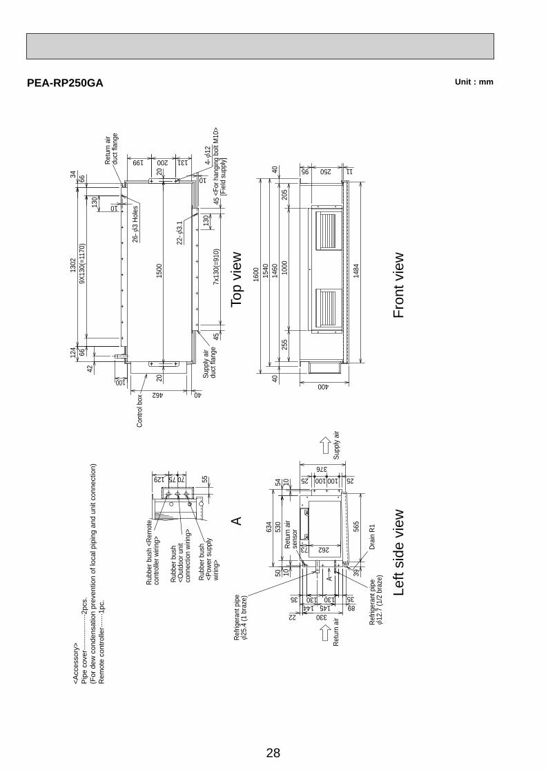
Unit : mmPEA-RP200GA
Retu
rn a
irse
nsor
ARubb
er b
ush
<Rem
ote
cont
rolle
r wirin
g>
Rubb
er b
ush
<Out
door
unit
conn
ectio
n wi
ring>
Rubb
er b
ush
<Pow
er su
pply
wirin
g> A
4-12
Drai
n R1
Top
view
Cont
rol b
ox
Retu
rn a
irdu
ct fl
ange
Supp
ly ai
rdu
ct fl
ange
<For
han
ging
bol
t M10
>[F
ield
sup
ply]
22-
3.1
24-
3 Ho
les
Refri
gera
nt p
ipe
9.52
(3/8
bra
ze)
Refri
gera
nt p
ipe
25.4
(1 b
raze
)
<Acc
esso
ry>
Pip
e co
ver··
······
······
·····2
pcs.
(For
dew
con
dens
atio
n pr
even
tion
of lo
cal p
ipin
g an
d un
it co
nnec
tion)
Rem
ote
cont
rolle
r·····
···1p
c.
Retu
rn a
ir
Left
side
vie
w
Supp
ly ai
r
Fron
t vie
w
75
55
129 70
42
124
34
131
530
50
95 250 11
7x13
0(=9
10)
10
130
130
4545
3131
1102
200
10
8x13
0(=1
040)
1300
20
199
100
40
20
462
144
1284
400
155
1000
105
4012
6040
1340
1400
565
39
22 330145 89
35 130 130 35
634
26273
1054 10
37625 100 100 25
28
Unit : mmPEA-RP250GA
Rubb
er b
ush
<Rem
ote
cont
rolle
r wiri
ng>
Rubb
er b
ush
<Out
door
uni
tco
nnec
tion
wirin
g>
Rubb
er b
ush
<Pow
er s
uppl
ywi
ring>
A
A
4-12
Drai
n R1
Top
view
Cont
rol b
ox
22-
3.1
<For
han
ging
bol
t M10
>[F
ield
sup
ply]Re
turn
air
duct
flan
ge
Supp
ly ai
rdu
ct fl
ange
26-
3 Ho
les
Left
side
vie
w
Supp
ly ai
rRe
turn
air
Fron
t vie
w
Retu
rn a
irse
nsor
<Acc
esso
ry>
Pip
e co
ver··
······
······
····2
pcs.
(For
dew
con
dens
atio
n pr
even
tion
of lo
cal p
ipin
g an
d un
it co
nnec
tion)
Rem
ote
cont
rolle
r·····
··1pc
.
Refri
gera
nt p
ipe
12.7
(1/2
bra
ze)
Refri
gera
nt p
ipe
25.4
(1 b
raze
)
42
144 145
75
55
70129
124
131
5053
0
34
130
95 250 111066
1302
1484
7x13
0(=9
10)
130
4545
200
20
100 20
199
40
1500
462
669X
130(
=117
0)
10
251001002510
10
1540
4014
6040
255
205
376
1000
1600
73 262
400
3956
5
5463
4
35 13089
33022
130 35
29
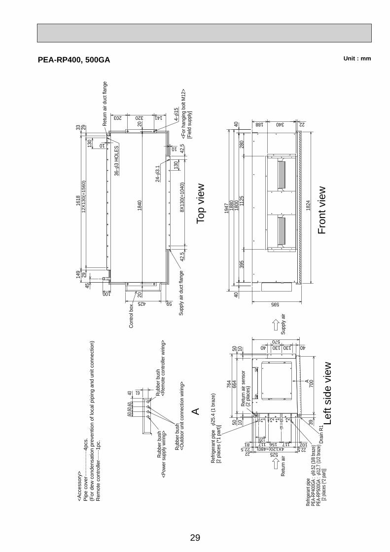
Unit : mmPEA-RP400, 500GA
45
Refrig
eran
t pipe
PEA-
RP40
0GA
: 9.5
2 (3/8
braz
e)PE
A-RP
500G
A :
12.7
(1/2
braz
e)
[2 pl
aces
(*2 p
art)]
*2*1 *2*1
Refri
gera
nt p
ipe
25.4
(1 b
raze
)[2
pla
ces
(*1 p
art)]
Retu
rn a
ir se
nsor
(2 p
lace
s)
Drai
n R1
24-
3.1
36-
3 HO
LES
Left
side
vie
wFr
ont v
iew
Top
view
Retu
rn a
irSu
pply
air
4-15
<For
han
ging
bol
t M12
>[F
ield
sup
ply]
Retu
rn a
ir du
ct fl
ange
Cont
rol b
ox
Supp
ly ai
r duc
t fla
nge
A
Rubb
er b
ush
<Rem
ote
cont
rolle
r wiri
ng>
Rubb
er b
ush
<Pow
er s
uppl
y wi
ring>
Rubb
er b
ush
<Out
door
uni
t con
nect
ion
wirin
g>
A
<Acc
esso
ry>
Pip
e co
ver··
······
······
····4
pcs.
(For
dew
con
dens
atio
n pr
even
tion
of lo
cal p
ipin
g an
d un
it co
nnec
tion)
Rem
ote
cont
rolle
r·····
··1pc
. 81 117 156 117
10
2018
40
10
4060
60
61
60
4040
1800
1880
5066
4
52522
10222.5
120
4X120(=480) 22.5
595
1824
5076
4
280
1125
395
340188 22
1947
5704013013040
10
33 2913
012
X13
0(=1
560)
29149
1618
100
42.5
130
8X13
0(=1
040)
42.5
10
203 320 141
20
425 59
700
39
30
Min.7250mm or greater with optionaldrain pump installation.
Req
uire
d sp
ace
(Indo
or u
nit)
Min
.50
Min
.220
Min
.150
550m
m o
r gre
ater
with
opt
iona
ldr
ain
pum
p in
stal
latio
n.
Min.250Min.5055m
m o
r gre
ater
with
left
or re
ar le
ft pi
png
or d
rain
pu
mp
inst
alla
tion. 197
387
192
599
Top
side
Fron
t sid
e
155
688
898
55
295
Fron
t sid
e (G
rille
ope
n)
169
158
184
457
Gas
pip
e 53
9 Li
quid
pip
e 61
0 D
rain
hos
e
Term
inal
blo
ck fo
r out
door
uni
t
Term
inal
blo
ck fo
r pow
er s
uppl
y (o
ptio
n)
Term
inal
blo
ck fo
rM
A-r
emot
e co
ntro
ller (
optio
n)
Em
erge
ncy
oper
atio
n sw
itch
(coo
ling/
heat
ing)
Und
er s
ide
Van
e (a
uto)
Ope
ratio
n la
mp
612
DE
FRO
ST/
STA
ND
BY
lam
p
Rec
eive
rK
nock
out h
ole
for l
ower
pip
ing
Louv
er (m
anua
l)K
nock
out h
ole
for l
ower
pip
ing
C
8
B
Siz
e
Refri
gera
nt p
ipe
: 6.
35Fl
ared
con
nect
ion
: 1/4
FRe
frige
rant
pip
e :
12.7
Flar
ed c
onne
ctio
n : 1
/2F
16
O.D
Liquid
pipe
Gas
pip
e
Drain
hose
Kno
ckou
t hol
efo
r rig
ht p
ipin
g
Rig
ht s
ide
Mou
nt b
oard
21.8
0 20 32.7
53.5
66 128.
515
3.5
231.
527
3.2
449
281
193.5180.3
278.3
167140115
0
174213238
394
449
253.
523
2.5
203.
517
8.5
166
103.
59178
.5
11641
28.5
160
372.3356.3327.5291.5265225200
125
70
15015
70
125
200225
265238
291.5327.5
372.3356.3
Indo
or u
nit o
utlin
eM
ount
boa
rd4-
9 B
olt h
ole
77-
5.1
Tapp
ing
scre
w h
ole
0
583.8C
ente
r mea
sure
men
t hol
e2.
5A
B43
65646
6046
43
59C
5612
.5
43
D43
65669
Kno
ckou
t hol
e fo
r pip
ing
Kno
ckou
t hol
efo
r lef
t pip
ing
Left
side
Slee
ve(p
urch
ased
loca
lly)
65~
8065
~80
Thro
ugh
hole
249
A 5
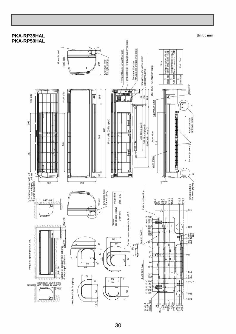
PKA-RP35HALPKA-RP50HAL
Unit : mm
31
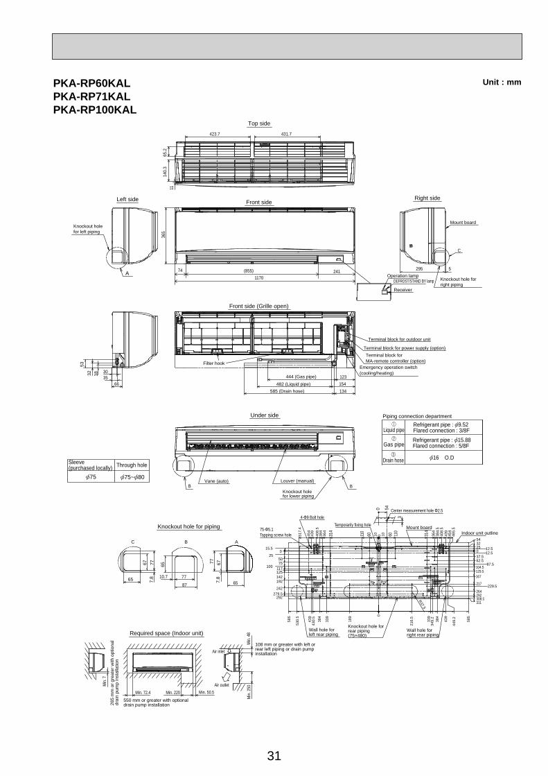
Unit : mmPKA-RP60KALPKA-RP71KALPKA-RP100KAL
Refrigerant pipe : 9.52Flared connection : 3/8F
16 O.D
Liquid pipe
Gas pipe
Drain hoseSleeve(purchased locally)
75 75~ 80
Through hole
5332 18
30
6635
65.2
423.7
1170
123154
B B
134
431.7
1114
0.3
365
A5
C
295
75-Φ5.1Tapping screw hole
4-Φ9 Bolt holeCenter measurement hole Φ2.50
314
364
384
408.
543
945
4
517.
4
585
439
384
339
189 0
216.
5
R37.5
339
384
585
439
349.
2
449.
2
430.
5
530.
5
110
110
314
54
15.50
5075
117125142
292279.5
242
192
25
100
3225
37.562.5
104.5129.5167
217
264292308.5311
0 12.512.5
87.5
229.5
364
384.
540
8.5
439
454
465.
5
60 60010 1054
3
C
65
67 65 6777777.
8
7.810.7
87
7765
B A
Top side
Front side
Front side (Grille open)
Terminal block for outdoor unit
Terminal block for power supply (option)Terminal block forMA-remote controller (option)
Emergency operation switch(cooling/heating)
Operation lampDEFROST/STAND BY lamp
Receiver
Knockout hole forright piping
Mount board
Right side
444 (Gas pipe) 482 (Liquid pipe)
585 (Drain hose)
Filter hook
Under side
Vane (auto)
Knockout holefor lower piping
Louver (manual)
Piping connection department
Indoor unit outline
Wall hole forright rear piping
Knockout hole forrear piping(75×480)
Wall hole forleft rear piping
Mount boardTemporarily fixing hole
108 mm or greater with left orrear left piping or drain pumpinstallation
Min.
48
Min.
250Air outlet
Air inlet
Min. 50.5Min. 220Min. 72.4550 mm or greater with optionaldrain pump installation26
5 m
m o
r gre
ater
with
opt
iona
ldr
ain
pum
p in
stal
latio
n
Min.
7
Required space (Indoor unit)
Knockout hole for piping
Knockout holefor left piping
Left side
Refrigerant pipe : 15.88Flared connection : 5/8F
74 (855) 241
32
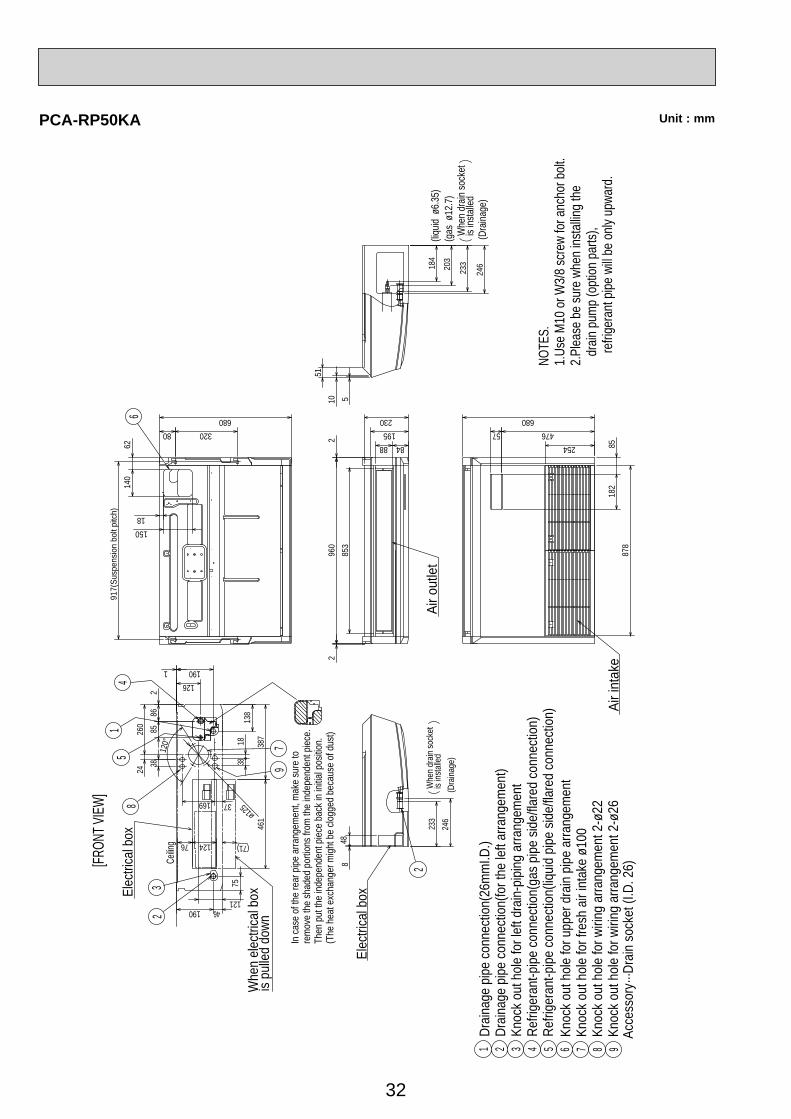
Unit : mmPCA-RP50KA
(Dra
inage
)
Whe
n dr
ain so
cket
is
insta
lled
2
246
Whe
n dr
ain so
cket
is
insta
lled
233
Whe
n ele
ctrica
l box
is pu
lled
down
Elec
trica
l box
NOTE
S.1.
Use
M10
or W
3/8
scre
w fo
r anc
hor b
olt.
2.Pl
ease
be
sure
whe
n ins
tallin
g th
e d
rain
pum
p (o
ption
par
ts),
re
frige
rant
pipe
will
be o
nly u
pwar
d.
Elec
trica
l box
233
Air o
utle
t
Air i
ntak
e96 7 851 2 3 4
Knoc
k out
hole
for u
pper
dra
in pip
e ar
rang
emen
tKn
ock o
ut h
ole fo
r fre
sh a
ir int
ake
ø100
Knoc
k out
hole
for w
iring
arra
ngem
ent 2
-ø22
Knoc
k out
hole
for w
iring
arra
ngem
ent 2
-ø26
Drain
age
pipe
conn
ectio
n(26
mm
I.D.)
Drain
age
pipe
conn
ectio
n(fo
r the
left
arra
ngem
ent)
Knoc
k out
hole
for l
eft d
rain-
piping
arra
ngem
ent
Refri
gera
nt-p
ipe co
nnec
tion(
gas p
ipe si
de/fla
red
conn
ectio
n)Re
frige
rant
-pipe
conn
ectio
n(liq
uid p
ipe si
de/fla
red
conn
ectio
n)
1
In ca
se o
f the
rear
pipe
arra
ngem
ent,
mak
e su
re to
re
mov
e th
e sh
aded
por
tions
from
the
indep
ende
nt p
iece.
Then
put
the
indep
ende
nt p
iece
back
in in
itial p
ositio
n.(T
he h
eat e
xcha
nger
migh
t be
clogg
ed b
ecau
se o
f dus
t)510
51
246
(Dra
inage
)
(gas
ø12.
7)(liq
uidø6
.35)
150
6214
0
18
917(
Susp
ensio
n bo
lt pi
tch)
320680
808488
195230
57254
476680
182
8587
8
848
260
2438
8586
2
126
169
121
190
1838
120°
960
22
853
12476
46190
75
387
461
3
8
Ceilin
g
51
4
7
184
203
ø125
6
9
37
138
2
[FRON
T VIEW
]
Acce
ssor
y···D
rain
sock
et (I
.D. 2
6)
(71)
33
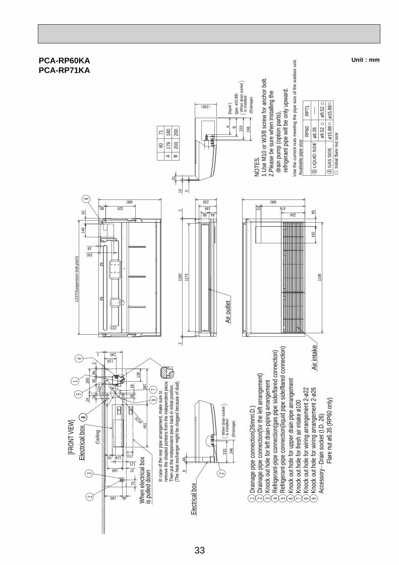
Unit : mm
(Dra
inage
)
Whe
n dr
ain so
cket
is
insta
lled
224
6
Whe
n dr
ain so
cket
is
insta
lled
233
Air i
ntak
e
541 2 3 6 7 8 9
Knoc
k out
hole
for u
pper
dra
in pip
e ar
rang
emen
tKn
ock o
ut h
ole fo
r fre
sh a
ir int
ake
ø100
Knoc
k out
hole
for w
iring
arra
ngem
ent 2
-ø22
Knoc
k out
hole
for w
iring
arra
ngem
ent 2
-ø26
Drain
age
pipe
conn
ectio
n(26
mm
I.D.)
Drain
age
pipe
conn
ectio
n(fo
r the
left
arra
ngem
ent)
Knoc
k out
hole
for l
eft d
rain-
piping
arra
ngem
ent
Refri
gera
nt-p
ipe co
nnec
tion(
gas p
ipe si
de/fla
red
conn
ectio
n)Re
frige
rant
-pipe
conn
ectio
n(liq
uid p
ipe si
de/fla
red
conn
ectio
n)
NOTE
S.1.
Use
M10
or W
3/8
scre
w fo
r anc
hor b
olt.
2.Pl
ease
be
sure
whe
n ins
tallin
g th
e d
rain
pum
p (o
ption
par
ts),
ref
riger
ant p
ipe w
ill be
only
upw
ard.
Air o
utlet
233
Elec
trica
l box
Whe
n ele
ctrica
l box
is pu
lled
down
Elec
trica
l box
97
In ca
se o
f the
rear
pipe
arra
ngem
ent,
mak
e su
re to
re
mov
e th
e sh
aded
por
tions
from
the
indep
ende
nt p
iece.
Then
put
the
indep
ende
nt p
iece
back
in in
itial p
ositio
n.(T
he h
eat e
xcha
nger
migh
t be
clogg
ed b
ecau
se o
f dus
t)
51051
246A B
236
150
6214
0
18
1237
(Sus
pens
ion
bolt
pitc
h)
320680
808488
195230
57254
476680
182
8511
98
848
260
2438
8586
2
126
169 37121
138
1901
1838
120°
1280
22
1173
12476
46190
75
387
461
23
85
14
ø125
68
[FRON
T VIEW
]
Ceilin
g
(Dra
inage
)
(gas
ø15
.88)
(liquid
)
Acce
ssor
y···D
rain
sock
et (I
.D. 2
6)
F
lare
nut ø
6.35
(RP6
0 on
ly)
A B
60 179
203
71 180
200
5 L
IQU
ID S
IDE
4 G
AS S
IDE
:Initi
al fl
are
nut s
ize
Use
the
curre
nt n
uts
mee
ting
the
pipe
siz
e of
the
outd
oor u
nit.
Avai
labl
e pi
pe s
ize R
P60
ø6.3
5ø9
.52
ø15.
88
RP7
1
ø9.5
2ø1
5.88
(71)
PCA-RP60KAPCA-RP71KA
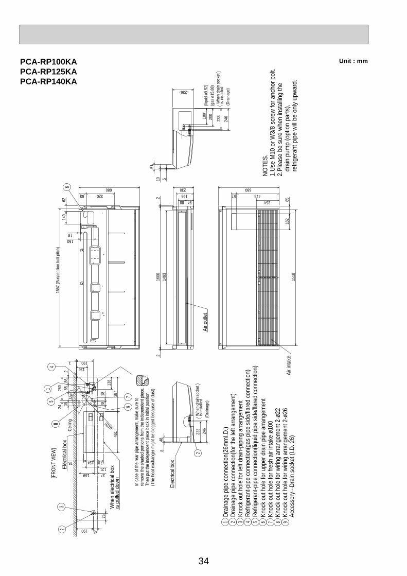
34
Unit : mm
(Dra
inage
)
Whe
n dr
ain so
cket
is
insta
lled
246
Whe
n dr
ain so
cket
is
insta
lled
233
Knoc
k out
hole
for u
pper
dra
in pip
e ar
rang
emen
tKn
ock o
ut h
ole fo
r fre
sh a
ir int
ake
ø100
Knoc
k out
hole
for w
iring
arra
ngem
ent 2
-ø22
Knoc
k out
hole
for w
iring
arra
ngem
ent 2
-ø26
96 7 8
Drain
age
pipe
conn
ectio
n(26
mm
I.D.)
Drain
age
pipe
conn
ectio
n(fo
r the
left
arra
ngem
ent)
Knoc
k out
hole
for l
eft d
rain-
piping
arra
ngem
ent
Refri
gera
nt-p
ipe co
nnec
tion(
gas p
ipe si
de/fla
red
conn
ectio
n)Re
frige
rant
-pipe
conn
ectio
n(liq
uid p
ipe si
de/fla
red
conn
ectio
n)51 2 3 4
Ceilin
g
[FRO
NT V
IEW
]
Elec
trica
l box
Whe
n el
ectri
cal b
oxis
pulle
d do
wn
2
NOTE
S.1.
Use
M10
or W
3/8
scre
w fo
r anc
hor b
olt.
2.Pl
ease
be
sure
whe
n in
stal
ling
the
dra
in p
ump
(opt
ion
parts
), r
efrig
eran
t pip
e wi
ll be
only
upwa
rd.
In ca
se o
f the
rear
pipe
arra
ngem
ent,
mak
e su
re to
re
mov
e th
e sh
aded
por
tions
from
the
indep
ende
nt p
iece.
Then
put
the
indep
ende
nt p
iece
back
in in
itial p
ositio
n.(T
he h
eat e
xcha
nger
migh
t be
clogg
ed b
ecau
se o
f dus
t)
51051
24618
020
0
(Dra
inage
)
(gas
ø15.
88)
(liquid
ø9.5
2)
236
150
6214
0
18
1557
320680
808488
195230
233
57254
476680
182
8515
18
848
260
2438
8586
2
126
169 37121
138
1901
1838
120°
1600
22
1493
12476
46190
75
387
461
71
23
51
4
7
ø125
6
88
9
Elec
trica
l box
Air o
utlet
Air i
ntak
e
(Sus
pens
ion b
olt p
itch)
Acce
ssor
y···D
rain
sock
et (I
.D. 2
6)
PCA-RP100KAPCA-RP125KAPCA-RP140KA

35
Unit : mm
Cei
ling
Less than
Less than
or more
Less
than
or m
ore
or m
ore
300
<Sus
pens
ion
bolt
pitc
h>
mod
el:P
AC
-SG
38K
F-E
(12p
cs.)
Filte
r ele
men
t for
the
exch
ange
1.U
se M
10 o
r W3/
8 sc
rew
for a
ncho
r bol
t.N
OTE
S.
· Opt
iona
l par
ts:d
uct f
lang
e(
200
). m
odel
: PA
C-S
F28O
F-E
(1 p
c.)
Kno
ckou
t hol
e fo
r wiri
ng a
rran
gem
ent :
2-
27
(122
)
<Filt
er c
onto
ur d
imen
sion
>
16
hand
le
100
100
1136
366
480
176
318
650
<Fle
xibl
e ho
se(a
cces
sory
)>
Term
inal
blo
ck b
ox
Term
inal
blo
ck(r
emot
e co
ntro
ller)
Term
inal
blo
ck(in
door
/out
door
con
nect
ing
line)
78
Insp
ectio
n po
rt
(pip
e se
nsor
)Th
e ha
lf bo
ttom
of F
AN
CA
SIN
Gca
n be
sep
arat
ed.
Adj
usta
ble
part
288
360
<Air outlet>
<Sus
pens
ion
bolt
pitc
h>
<Air
outle
t>
<Air
inta
ke>
<Air intake>
Filte
r (3-
piec
es)
Term
inal
blo
ck b
ox
5 2
1
4
3
Kno
ckou
t hol
e fo
r upp
er re
frige
rant
-pip
e ar
rang
emen
t
69
21
Flex
ible
hos
e(ac
cess
ory)
D
rain
age
pipe
con
nect
ion(
26m
m I.
D.)
Ref
riger
ant-p
ipe
conn
ectio
n(ga
s pi
pe s
ide/
flare
d co
nnec
tion
: 5/8
inch
)
38
10585
90°
Ele
ctric
al b
ox
Rea
r wal
l
500
250
2 ~ 3
(Gap to ceiling)
Allo
win
g cl
eara
nces
<gas><liquid>
Kno
ckou
t hol
e (d
uct f
or fr
esh
air i
ntak
e): 2
- 2
00
Kno
ckou
t hol
e fo
r beh
ind
refri
gera
nt-p
ipin
g ar
rang
emen
t
Ref
riger
ant-p
ipe
conn
ectio
n(liq
uid
pipe
sid
e/fla
red
conn
ectio
n : 3
/8 in
ch)
Sus
pens
ion
bolt
130
210
45
165120
1224
1180
75
1136
986
1098
70
243
254
175
197
11021
130
15
258110102
320
80
90
140
1875
70~90
650
13
289
75280
495
43
295
222
200
PCA-RP71HA

36
Unit : mm
Cei
ling
Less than
Less than
Less
than
or more
or m
ore
or m
ore
Ref
riger
ant-p
ipe
conn
ectio
n(ga
s pi
pe s
ide/
flare
d co
nnec
tion
: 5/8
inch
)
Kno
ckou
t hol
e (d
uct f
or fr
esh
air i
ntak
e) :
2-
200
· Opt
iona
l par
ts:d
uct f
lang
e(
200
). m
odel
: PA
C-S
F28O
F-E
(1 p
c.)
Flex
ible
hos
e(ac
cess
ory)
D
rain
age
pipe
con
nect
ion(
26m
m I.
D.)
Term
inal
blo
ck(in
door
/out
door
con
nect
ing
line)
Term
inal
blo
ck(r
emot
e co
ntro
ller)
Ref
riger
ant-p
ipe
conn
ectio
n(liq
uid
pipe
sid
e/fla
red
conn
ectio
n : 3
/8 in
ch)
Kno
ckou
t hol
e fo
r beh
ind
refri
gera
nt-p
ipin
g ar
rang
emen
tK
nock
out h
ole
for u
pper
refri
gera
nt-p
ipe
arra
ngem
ent
Kno
ckou
t hol
e fo
r wiri
ng a
rran
gem
ent :
2-
27
Allo
win
g cl
eara
nces
Rea
r wal
l
(Gap to ceiling)
NO
TES
.1.
Use
M10
or W
3/8
scre
w fo
r anc
hor b
olt.
Use
the
curr
ent n
uts
mee
ting
the
pipe
siz
eof
the
outd
oor u
nit.
mod
el:P
AC
-SG
38K
F-E
(12p
cs.)
Filte
r ele
men
t for
the
exch
ange
<Sus
pens
ion
bolt
pitc
h>
(122
)24
6
hand
le
16
<Fle
xibl
e ho
se(a
cces
sory
)>
Term
inal
blo
ck b
ox
78
<Filt
er c
onto
ur d
imen
sion
>
Insp
ectio
n po
rt
(pip
e se
nsor
)Th
e ha
lf bo
ttom
of
FAN
CA
SIN
Gca
n be
sep
arat
ed.
Adj
usta
ble
part
288
360
<Air outlet>
<Sus
pens
ion
bolt
pitc
h>
<Air
outle
t>
<Air
inta
ke>
<Air intake>
Filte
r (4-
piec
es)
Term
inal
blo
ck b
ox
5 2
1
4
3
69
21
176
38210
10585
45 165
222
200
440
440
298
130
90°
650
300
100
1520
100
Ele
ctric
al b
ox
500
250
2~3
<gas><liquid>
Sus
pens
ion
bolt
70
243
254
175
197
11021
130
15
258
1482
110102
1370
75
1608
320
8015
64
1520
90120
140
1875
70~90
650
13
289
75280
495
43
295
PCA-RP125HA
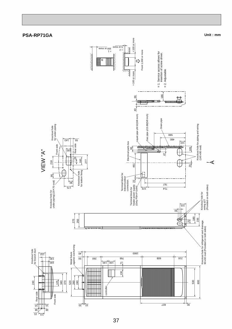
37
Unit : mm
125
240
Fron
t sid
e
Met
al fi
xtur
eag
ains
t ove
rturn
ing
cont
rolle
r
Rea
r sid
e
Kno
ckou
t hol
efo
r bra
nch
duct
100
1038 38
50 260130 130
766
1900
608
50
115
714123
767
110480
590
216
40
827 3020 10
11115
130
132
VIE
W "A
"
A
340
370
520
260
240
130
71
530
600
270
250
70
180
235
Kno
ckou
t hol
e fo
rw
iring
27(P
rovi
ded
on b
oth
side
s)
Kno
ckou
t hol
e fo
r ref
riger
ant a
nd d
rain
age
90
60 o
val (
Pro
vide
d on
bot
h si
des)
Kno
ckou
t hol
e fo
r pip
ing
and
wiri
ng(1
40
80 o
val)
2010
5
Term
inal
blo
ck fo
r in
door
/out
door
conn
ectio
n.E
lect
rical
par
ts b
ox
Liqu
id p
ipe
9.52
(3/8
inch
)
1. S
ervi
ce a
cces
s al
low
s fo
r
inse
rtion
of s
crew
driv
er.
2. A
djus
tabl
e
Gas
pip
e 15
.88(
5/8
inch
)
Dra
in p
ipe
Term
inal
blo
ck fo
r he
ater
pow
er s
uppl
y(O
nly
PS
H-P
·GA
H)
9546
122
47Fron
t sid
e
Rea
r sid
eK
nock
out h
ole
for b
otto
m fi
Kno
ckou
t hol
efo
r und
er-p
ipin
g
Kno
ckou
t hol
e fo
r un
der-
pipi
ng(1
20
70 o
val)
277
16020
218
175
90
55143
100
95
4066 18
6
100
or m
ore
100
or m
ore
25 or more
1300 or more
Fron
t 1,0
00 o
r mor
e
10
PSA-RP71GA
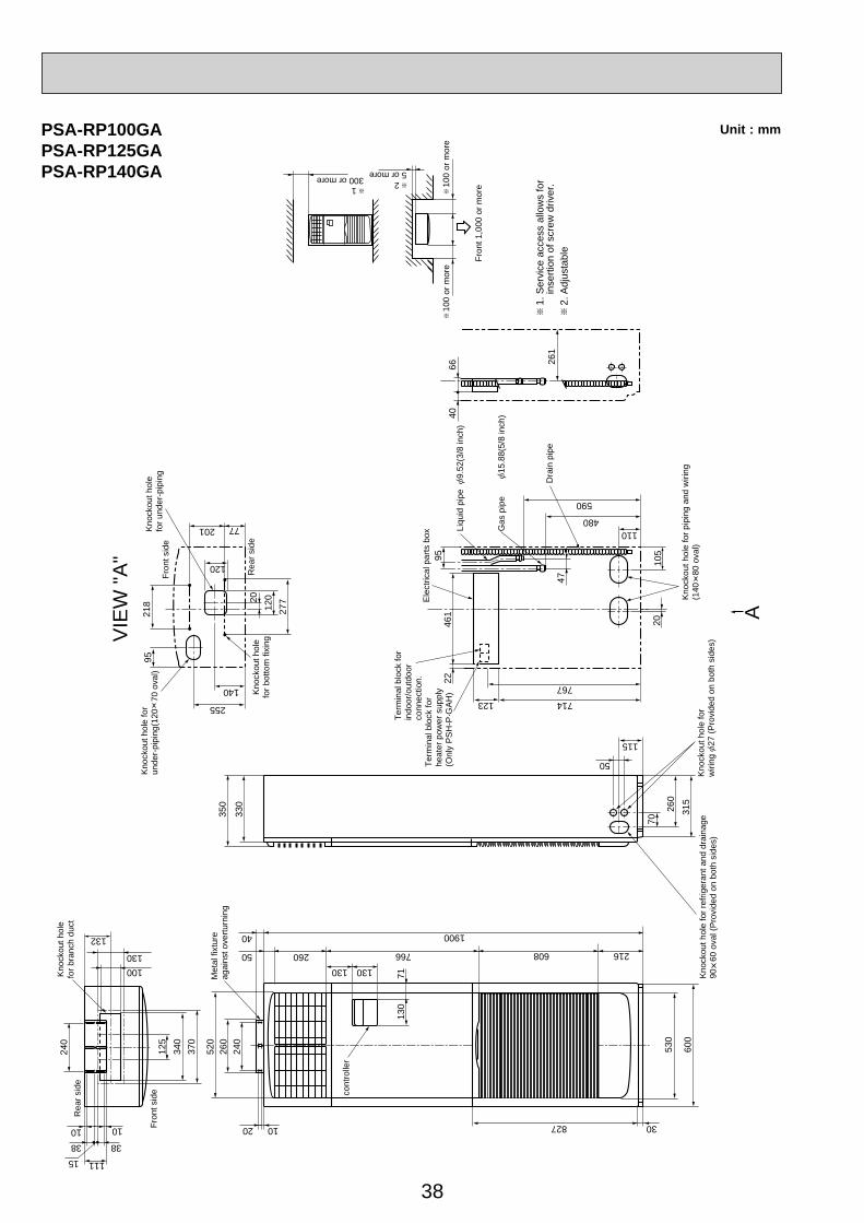
38
Unit : mm
125
240
Fron
t sid
e
Met
al fi
xtur
eag
ains
t ove
rturn
ing
cont
rolle
r
Rea
r sid
e
Kno
ckou
t hol
efo
r bra
nch
duct
100
1038 38
50 260130 130
766
1900
608
50
115
714123
767
110480
590
216
40
827 3020 10
11115
130
132
340
370
520
260
240
130
71
530
600
350
330
70
260
315
Kno
ckou
t hol
e fo
rw
iring
27 (P
rovi
ded
on b
oth
side
s)K
nock
out h
ole
for r
efrig
eran
t and
dra
inag
e90
60
ova
l (P
rovi
ded
on b
oth
side
s)
Kno
ckou
t hol
e fo
r pip
ing
and
wiri
ng(1
40
80 o
val)
2010
5
Ele
ctric
al p
arts
box
Liqu
id p
ipe
9.52
(3/8
inch
)
1. S
ervi
ce a
cces
s al
low
s fo
r
inse
rtion
of s
crew
driv
er.
2. A
djus
tabl
e
Gas
pip
e 15
.88(
5/8
inch
)
Dra
in p
ipe
9546
122
47Fron
t sid
e
Rea
r sid
eK
nock
out h
ole
for b
otto
m fi
Kno
ckou
t hol
efo
r und
er-p
ipin
g
Kno
ckou
t hol
e fo
r un
der-
pipi
ng(1
20
70 o
val)
277
12020
218
255
140
77201
120
95
4066 26
1
100
or m
ore
100
or m
ore
25 or more
1300 or more
Fron
t 1,0
00 o
r mor
e
10
VIE
W "A
"
A
Term
inal
blo
ck fo
r in
door
/out
door
conn
ectio
n.Te
rmin
al b
lock
for
heat
er p
ower
sup
ply
(Onl
y P
SH
-P·G
AH
)
PSA-RP100GAPSA-RP125GAPSA-RP140GA
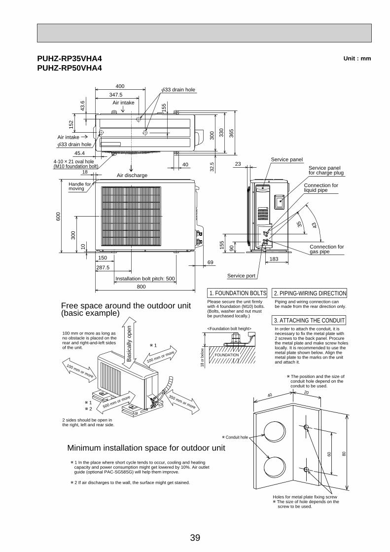
39
Unit : mmPUHZ-RP35VHA4PUHZ-RP50VHA4
Service panel for charge plug
1 In the place where short cycle tends to occur, cooling and heating capacity and power consumption might get lowered by 10%. Air outlet guide (optional PAC-SG58SG) will help them improve.
2 If air discharges to the wall, the surface might get stained.
Minimum installation space for outdoor unit
100 mm or more as long as no obstacle is placed on the rear and right-and-left sides of the unit.
2 sides should be open in the right, left and rear side.
2 1
100 mm or more
500 mm or more
Basi
cally
ope
n
100 mm or more
Free space around the outdoor unit (basic example)
350 mm or more
1
Air intake
Air discharge
Air intake
Connection for gas pipe
Service port
Connection for liquid pipe
Service panel4-10 21 oval hole(M10 foundation bolt)
33 drain hole
33 drain hole
43.6
152
155
400347.5
45.4
365
330
300
40
Handle for moving
600
10
300
150
287.5
Installation bolt pitch: 500800
69
35 43
183
90155
23
32.5
18
1. FOUNDATION BOLTS 2. PIPING-WIRING DIRECTIONPiping and wiring connection can be made from the rear direction only.
3. ATTACHING THE CONDUITIn order to attach the conduit, it is necessary to fix the metal plate with 2 screws to the back panel. Procure the metal plate and make screw holes locally. It is recommended to use the metal plate shown below. Align the metal plate to the marks on the unit and attach it.
<Foundation bolt height>
Please secure the unit firmly with 4 foundation (M10) bolts. (Bolts, washer and nut must be purchased locally.)
18 o
r bel
ow
4020
60 80
Conduit hole
The position and the size of conduit hole depend on the conduit to be used.
Holes for metal plate fixing screw The size of hole depends on the
screw to be used.
FOUNDATION
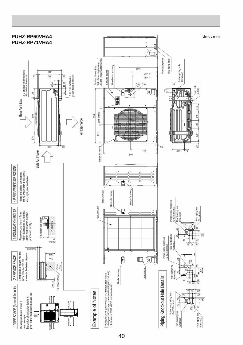
40
Unit : mm
Air
Inta
ke
Rear
Air
Inta
ke
Hand
le fo
r mov
ing
Hand
le fo
r mov
ing
322
950
473943
23
*1 447*1 431
673
21
Hand
le fo
r mov
ing
Han
dle
for m
ovin
g
Ser
vice
pan
el
Earth
term
inal
Left·
··Pow
er su
pply
wirin
gRe
ight··
·Indo
or/O
utdo
or w
iring
Term
inal C
onne
ction
s
Rear
pipi
ng co
ver
Fron
t pipi
ng co
ver
Side
Air
Inta
ke
Hand
le fo
r mov
ing
4054
2837019
417
53
5741
600
175
175
330
Rear
Air In
take
Air D
ischa
rge
Side A
ir Inta
keIns
tallat
ion Fe
et
2-U
Shap
ed n
otch
ed h
oles
(Fou
ndat
ion
Bolt
M10
)
2-12
36
oval
hol
es(F
ound
atio
n Bo
lt M
10)
3022
014
514
514
530
81219
71
71 Botto
m p
ipin
g ho
le(K
nock
out)
Drai
n ho
le(5
-33
)
Pipin
g Kn
ocko
ut H
ole D
etail
s 1955
232792
92
4075
7363Righ
t pipi
ng h
ole(K
nock
out)
Righ
t tru
nking
hole
(Kno
ckou
t)
Powe
r sup
ply w
iring
hole
(2-
27Kn
ocko
ut)
92
275573 2363
40 926545
Fron
t pipi
ng h
ole(K
nock
out)
Fron
t tru
nking
hole
(Kno
ckou
t)
Powe
r sup
ply w
iring
hole
(2-
27Kn
ocko
ut)
92
4045 65
92
2755
237363
Rear
pipi
ng h
ole(K
nock
out)
Rear
trun
king
hole
(Kno
ckou
t)
Powe
r sup
ply w
iring
hole
(2-
27Kn
ocko
ut)
92
Exam
ple
of N
otes
Ref
riger
ant G
AS p
ipe
conn
ctio
n (F
LARE
)15
.88(
5/8
inch
) R
efrig
eran
t LIQ
UID
pipe
con
nect
ion
(FLA
RE)
9.52
(3/8
inch
)*1
...In
dica
tion
of S
TOP
VALV
E co
nnec
tion
loca
tion.
Ove
r
Over
Less than
Pipin
g an
d wi
ring
conn
ectio
nsca
n be
mad
e fro
m 4
dire
ction
s:fro
nt, r
ight,
rear
and
belo
w.
4 PIPI
NG-W
IRING
DIRE
CTION
S3 F
OUND
ATIO
N BO
LTS
2 SER
VICE S
PACE
1 FRE
E SPA
CE (A
round
the u
nit)
The
diagr
am b
elow
show
s aba
sic e
xam
ple.
Expla
ntion
of p
artic
ular d
etail
s is
given
in th
e ins
talla
tion
man
uals
etc.
Ove
r10
500
500
Over100
Dim
ensio
ns o
f spa
ce n
eede
dfo
r ser
vice
acce
ss a
resh
own
in th
e be
low d
iagra
m.
Serv
ice s
pace
30
Plea
se se
cure
the
unit f
irmly
with
4 fo
unda
tion
(M10
) bolt
s.(B
olts a
nd w
ashe
rs m
ust b
e pu
rcha
sed
locall
y.)
<Fou
ndati
on bo
lt heig
ht>
FOUN
DATIO
N
over
100m
mov
er 50
0mm
over
10mm
FREE
over
10mm
PUHZ-RP60VHA4PUHZ-RP71VHA4
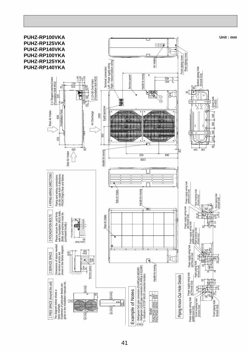
41
Unit : mmPUHZ-RP100VKAPUHZ-RP125VKAPUHZ-RP140VKAPUHZ-RP100YKAPUHZ-RP125YKAPUHZ-RP140YKA
FOUN
DATIO
N
30
Serv
ice sp
ace
150 500
500
10
The
diagr
am b
elow
show
s aba
sic e
xam
ple.
Expla
ntion
of p
artic
ular d
etail
s are
given
in th
e ins
talla
tion
man
uals
etc.
Dim
ensio
ns o
f spa
ce n
eede
dfo
r ser
vice
acce
ss a
resh
own
in th
e be
low d
iagra
m.
<Fou
ndat
ion
bolt
heig
ht>
Plea
se se
cure
the
unit f
irmly
with
4 fo
unda
tion
(M10
) bolt
s.(B
olts a
nd w
ashe
rs m
ust b
e pu
rcha
sed
locall
y.)
1 FRE
E SPA
CE (A
round
the u
nit)
2 SER
VICE S
PACE
3 FOU
NDAT
ION
BOLT
S4 P
IPING
-WIRI
NG DI
RECT
IONS
Pipin
g an
d wi
ring
conn
ectio
nsca
n be
mad
e fro
m 4
dire
ction
s:FR
ONT,R
ight,R
ear a
nd B
elow.
Piping
Kno
ck-O
ut Ho
le De
tails
PUHZ
-RP1
00~1
40VK
APU
HZ-R
P100
~140
YKA
Mod
el
919
1067A
···Refr
igeran
t GAS
pipe
conn
ectio
n (FL
ARE)
ø15.8
8(5/8F
)···R
efrige
rant L
IQUI
D pip
e con
necti
on (F
LARE
)ø 9.
52(3/
8F)
*1···I
ndica
tion o
f STO
P VA
LVE
conn
ectio
n loc
ation
.
Less than
1 2
Over Over
Over
Over
Exa
mpl
e of
Not
es
Side A
ir Inta
ke
Rear
Air In
take
Hand
le for
mov
ing
Hand
le for
mov
ing
Powe
r sup
ply w
iring h
ole(ø2
7Kno
ck-O
ut)
Fron
t pipi
ng ho
le(K
nock
-Out)
Fron
t tru
nking
hole
(Kno
ck-O
ut)
Powe
r sup
ply w
iring h
ole(ø
40Kn
ock-O
ut)60
55
63 7355 27
26
759260 ø92
Powe
r sup
ply w
iring h
ole(ø2
7Kno
ck-O
ut)Ri
ght p
iping
hole
(Kno
ck-O
ut)
Righ
t tru
nking
hole
(Kno
ck-O
ut)
Powe
r sup
ply w
iring
hole
(ø40
Knoc
k-Ou
t)
7550
2627
63 73
299255
92
60 ø92
Powe
r sup
ply w
iring
hole
(ø27
Knoc
k-Ou
t)
Rear
pipi
ng h
ole(K
nock
-Out
)
Rear
trun
king
hole
(Kno
ck-O
ut)
Powe
r sup
ply w
iring
hole
(ø40
Knoc
k-Ou
t)
75
6055
63 73 2655 27
60
92
ø92
Over
10mm
Over
10mm
FREE
Over
150m
mOv
er 10
00mm
Hand
le for
mov
ing
Earth
term
inal
Serv
ice p
anel
21
Hand
le for
mov
ingTe
rmina
l con
necti
onLe
ft···P
ower
supp
ly wi
ring
Righ
t···Ind
oor/O
utdoo
r wirin
g
632
*1 450A
369
362
26
1338
1050
*1 442
Air i
ntak
e
Fron
t pipi
ng co
ver
Rear
pipi
ng co
ver
Drain
hole
(5-ø
33)
Botto
m p
iping
hole
(Kno
ck-O
ut)
81
45154 136
110
160
160
160
86
Rear
Air
Inta
ke
Air D
ischa
rge
Side
Air
Inta
ke
Insta
llatio
n Fe
et
2-U
Shap
ed n
otch
ed h
oles
(Fou
ndat
ion B
olt M
10)
2-12
×36
Oval
holes
(Fou
ndat
ion B
olt M
10)
28370
60
30
225
225
330
600
41719
7042
40 5356 0
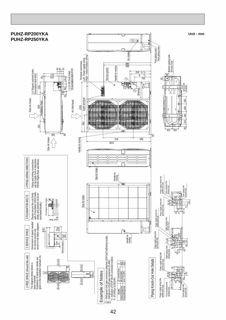
42
Unit : mmPUHZ-RP200YKAPUHZ-RP250YKA
FOUN
DATIO
N
30
Serv
ice sp
ace
150 500
500
10
The
diagr
am b
elow
show
s aba
sic e
xam
ple.
Expla
ntion
of p
artic
ular d
etail
s are
given
in th
e ins
talla
tion
man
uals
etc.
Dim
ensio
ns o
f spa
ce n
eede
dfo
r ser
vice
acce
ss a
resh
own
in th
e be
low d
iagra
m.
<Fou
ndat
ion
bolt
heig
ht>
Plea
se se
cure
the
unit f
irmly
with
4 fo
unda
tion
(M10
) bolt
s.(B
olts a
nd w
ashe
rs m
ust b
e pu
rcha
sed
locall
y.)
1 FRE
E SPA
CE (A
round
the u
nit)
2 SER
VICE S
PACE
3 FOU
NDAT
ION
BOLT
S4 P
IPING
-WIRI
NG DI
RECT
IONS
Pipin
g an
d wi
ring
conn
ectio
nsca
n be
mad
e fro
m 4
dire
ction
s:FR
ONT,R
ight,R
ear a
nd B
elow.
Less than
Over Over
Over
Over
Over
10mm
Over
10mm
FREE
Over
150m
mOv
er 10
00mm
PUHZ
-RP2
00YK
APU
HZ-R
P250
YKA
Mod
el
424
450A
conn
ectio
nø9
.52(
3/8F
)ø1
2.7(
1/2F
)
···Refr
igeran
t GAS
pipe
conn
ectio
n (att
ache
d JOI
NT)ø
25.4(
Braz
ing lo
cally
)···R
efrige
rant L
IQUI
D pip
e con
necti
on (F
LARE
)*1
···Ind
icatio
n of S
TOP
VALV
E co
nnec
tion l
ocati
on.
*2···(
FLAR
E)ø 1
9.05(3
/4F)
1 2
2
Exa
mpl
e of
Not
es
Piping
Kno
ck-O
ut Ho
le De
tails
Powe
r sup
ply w
iring h
ole(ø2
7Kno
ck-O
ut)
Fron
t pipi
ng ho
le(K
nock
-Out)
Fron
t tru
nking
hole
(Kno
ck-O
ut)
Powe
r sup
ply w
iring h
ole(ø
40Kn
ock-O
ut)
6055
63 7355 27
26
759260 ø92
Powe
r sup
ply w
iring h
ole(ø2
7Kno
ck-O
ut)
Righ
t pipi
ng h
ole(K
nock
-Out
)Ri
ght t
runk
ing h
ole(K
nock
-Out
)
Powe
r sup
ply w
iring
hole
(ø40
Knoc
k-Ou
t)
7550
262763 73 29
9255
92
60 ø92
Powe
r sup
ply w
iring
hole
(ø27
Knoc
k-Ou
t)
Rear
pipi
ng h
ole(K
nock
-Out
)
Rear
trun
king
hole
(Kno
ck-O
ut)
Powe
r sup
ply w
iring
hole
(ø40
Knoc
k-Ou
t)
75
6055
63 73 2655 27
60
92
ø92
Drain
hole
(5-ø
33)
Botto
m p
iping
hole
(Kno
ck-O
ut)
81
45154 136
110
160
160
160
86
1050
Rear
Air
Inta
ke
Air D
ischa
rge
Side
Air
Inta
ke
Insta
llatio
n Fe
et
2-U
Shap
ed n
otch
ed h
oles
(Fou
ndat
ion B
olt M
10)
2-12
×36
Oval
holes
(Fou
ndat
ion B
olt M
10)
28370
60
30
225
225
330
600
41719
7042
40 5356 0
Hand
le for
movin
g
Rear
Air In
take
Side A
ir Inta
ke
Hand
le for
mo
ving
632 36926
1338
Hand
le for
mov
ing
Hand
le for
mov
ing
Earth
term
inal
362
Braz
ing
Serv
ice p
anel
Term
inal c
onne
ction
Left··
·Pow
er su
pply
wirin
gRi
ght···
Indoo
r/Outd
oor w
iring
*1,*2 : 442
982986
*1 A342
Air i
ntak
e
2
1
Fron
t pipi
ng co
ver
Rear
pipi
ng co
ver

43
WIRED REMOTE CONTROLLERWIRELESS REMOTE CONTROLLER
130
120
19.5
159.
3
55
58
19Unit : mm
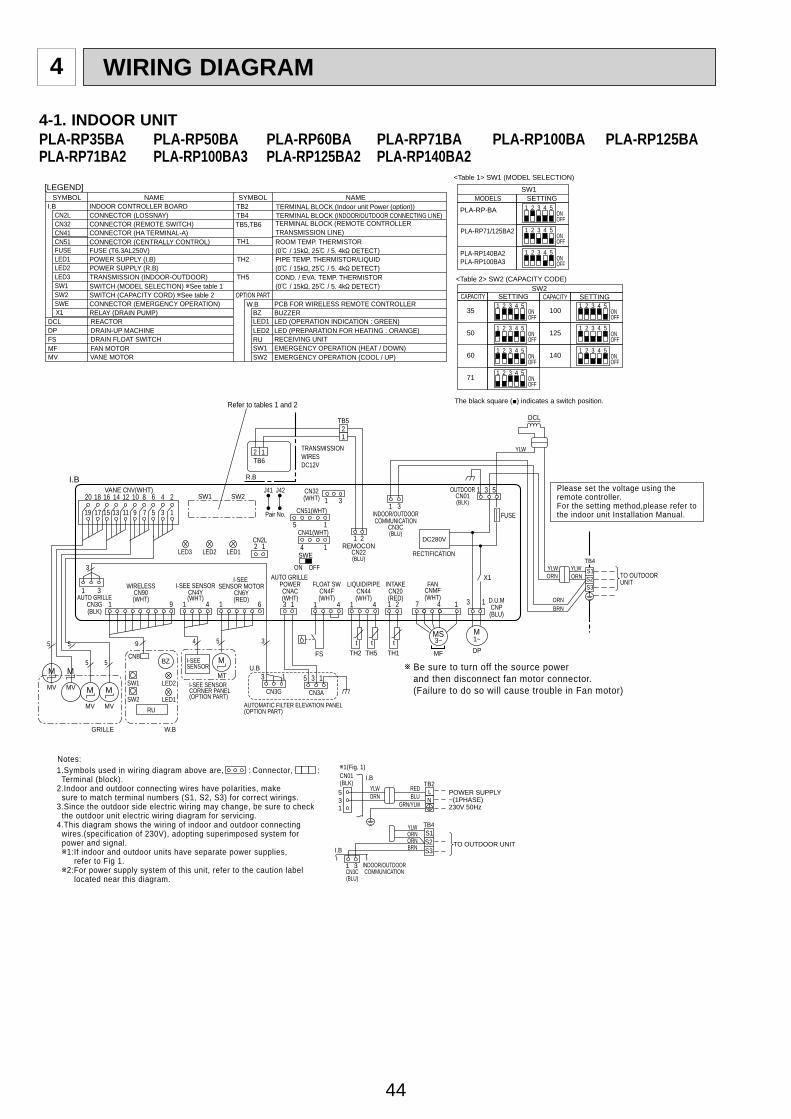
44
4-1. INDOOR UNITPLA-RP35BA PLA-RP50BA PLA-RP60BA PLA-RP71BA PLA-RP100BA PLA-RP125BAPLA-RP71BA2 PLA-RP100BA3 PLA-RP125BA2 PLA-RP140BA2
WIRING DIAGRAM4
INDOOR/OUTDOORCOMMUNICATION
CN3C(BLU)
1 1 4 1 69
1
1
3
1 3
4
5 1
4 1
1
2
3
4
5
6
7
8
9
10
11
12
13
14
15
16
17
18
19
20
CN2L
ON OFF
SWE
J42J41SW2SW1
LED3 LED2 LED1
LED2
LED1RU
SW2
SW1
CNB
3
9
55
55 4 5 3 t t tFS TH2 TH5 TH1
MV
BZ
MV
MVMV
M M
M M
W.B
TB6
R.BI.B
MT
M
1 4
2 121
21
12
12
Refer to tables 1 and 2
TRANSMISSIONWIRESDC12V
TB4YLWORN
ORNBRN
YLW
YLW
ORN
DCL
TO OUTDOORUNIT
1 3 5
3 1
DC280V
X1
M1~DP
D.U.MCNP(BLU)
FUSE
OUTDOORCN01(BLK)
RECTIFICATION
S1S2S3
7 4 1
3~
MF
MS
CN3G
U.B
AUTOMATIC FILTER ELEVATION PANEL(OPTION PART)
CN3A
3 1
AUTO GRILLE POWERCNAC(WHT)
1 3
REMOCONCN22(BLU)
I-SEE SENSORCN4Y(WHT)
I-SEESENSOR MOTOR
CN6Y(RED)
WIRELESSCN90(WHT)AUTO GRILLE
CN3G(BLK)
I-SEE SENSOR CORNER PANEL(OPTION PART)
I-SEESENSOR
GRILLE
VANE CNV(WHT)
Pair No.
FANCNMF(WHT)
INTAKECN20(RED)
FLOAT SWCN4F(WHT)
LIQUID/PIPECN44(WHT)
TB5
CN32(WHT)
CN51(WHT)
CN41(WHT)
<Table 1> SW1 (MODEL SELECTION)
SW1
Be sure to turn off the source power and then disconnect fan motor connector. (Failure to do so will cause trouble in Fan motor)
1313 5
<Table 2> SW2 (CAPACITY CODE)
SETTING
35
CAPACITYSW2
ONOFF
1 2 3 4 5100 ON
OFF
1 2 3 4 5
50 ONOFF
1 2 3 4 5125 ON
OFF
1 2 3 4 5
60 ONOFF
1 2 3 4 5140 ON
OFF
1 2 3 4 5
71 ONOFF
1 2 3 4 5
CAPACITY SETTING
SETTING
PLA-RP·BA
MODELS
ONOFF
1 2 3 4 5
ONOFF
1 2 3 4 5
ONOFF
1 2 3 4 5
PLA-RP71/125BA2
PLA-RP140BA2PLA-RP100BA3
The black square (■) indicates a switch position.
SYMBOL SYMBOLNAME NAMEI.B INDOOR CONTROLLER BOARD
FUSE (T6.3AL250V)
CONNECTOR (LOSSNAY)CONNECTOR (REMOTE SWITCH)CONNECTOR (HA TERMINAL-A)CONNECTOR (CENTRALLY CONTROL)
POWER SUPPLY (I.B)POWER SUPPLY (R.B)TRANSMISSION (INDOOR-OUTDOOR)
RELAY (DRAIN PUMP)
SWITCH (MODEL SELECTION) See table 1SWITCH (CAPACITY CORD) See table 2CONNECTOR (EMERGENCY OPERATION)
FAN MOTORVANE MOTOR
DRAIN-UP MACHINEDRAIN FLOAT SWITCH
TERMINAL BLOCK (Indoor unit Power (option))TERMINAL BLOCK (INDOOR/OUTDOOR CONNECTING LINE)TERMINAL BLOCK (REMOTE CONTROLLERTRANSMISSION LINE)
REACTOR
ROOM TEMP. THERMISTOR(0 / 15k , 25 / 5. 4k DETECT)PIPE TEMP. THERMISTOR/LIQUID(0 / 15k , 25 / 5. 4k DETECT)COND. / EVA. TEMP. THERMISTOR(0 / 15k , 25 / 5. 4k DETECT)
MF
FUSE
MV
DP
CN2L
FS
CN32
TB2
CN41CN51
TB4
DCL
LED1
TB5,TB6
LED2
TH1
LED3
X1
TH2
SW1TH5
SW2SWE
[LEGEND]
TO OUTDOOR UNIT
135
31
CN01(BLK)
ORNYLW
BLURED
GRN/YLW
I.B1(Fig. 1)
I.B
TB2POWER SUPPLY~(1PHASE)230V 50Hz
ORNORN
YLW
BRN
TB4
INDOOR/OUTDOORCOMMUNICATIONCN3C
(BLU)
LN
S1S2S3
1.SymboIs used in wiring diagram above are, : Connector, : Terminal (block).2.Indoor and outdoor connecting wires have poIarities, make sure to match terminal numbers (S1, S2, S3) for correct wirings.3.Since the outdoor side electric wiring may change, be sure to check the outdoor unit electric wiring diagram for servicing.4.This diagram shows the wiring of indoor and outdoor connecting wires.(specification of 230V), adopting superimposed system for power and signal. 1:If indoor and outdoor units have separate power supplies, refer to Fig 1. 2:For power supply system of this unit, refer to the caution label located near this diagram.
Please set the voltage using theremote controller.For the setting method,please refer tothe indoor unit Installation Manual.
W.B
RU
BZLED1LED2
SW1SW2
OPTION PARTPCB FOR WIRELESS REMOTE CONTROLLER
RECEIVING UNIT
BUZZERLED (OPERATION INDICATION : GREEN)LED (PREPARATION FOR HEATING : ORANGE)
EMERGENCY OPERATION (HEAT / DOWN)EMERGENCY OPERATION (COOL / UP)
Notes:
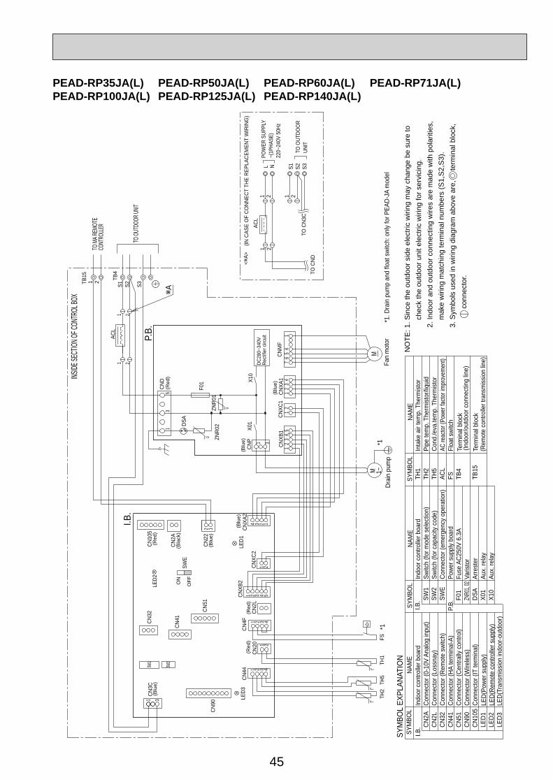
45
PEAD-RP35JA(L) PEAD-RP50JA(L) PEAD-RP60JA(L) PEAD-RP71JA(L)PEAD-RP100JA(L) PEAD-RP125JA(L) PEAD-RP140JA(L)
12
1 3
5
1
124 3
21542 3
32
14
2121
4
1 3
MM
45
67
12
11
23
35
1
321 3 4
41 2
21
INSIDE
SECT
ION OF
CONT
ROL B
OX
Conn
ecto
r (0-
10V
Anal
og in
put)
Conn
ecto
r (IT
term
inal
)Co
nnec
tor (
Wire
less
)
Indo
or c
ontro
ller b
oard
NO
TE: 1
. Sin
ce th
e ou
tdoo
r sid
e el
ectri
c w
iring
may
cha
nge
be s
ure
to
ch
eck
the
outd
oor u
nit e
lect
ric w
iring
for s
ervi
cing
.
2. In
door
and
out
door
con
nect
ing
wire
s ar
e m
ade
with
pol
ariti
es,
mak
e w
iring
mat
chin
g te
rmin
al n
umbe
rs (S
1,S
2,S
3).
3.
Sym
bols
use
d in
wiri
ng d
iagr
am a
bove
are
, te
rmin
al b
lock
,
conn
ecto
r.Va
risto
r
Aux.
rela
y
Fuse
AC2
50V
6.3A
Conn
ecto
r (Ce
ntra
lly c
ontro
l)Co
nnec
tor (
HA te
rmin
al-A
)
LED(
Rem
ote
cont
rolle
r sup
ply)
Indo
or c
ontro
ller b
oard
Conn
ecto
r (Re
mot
e sw
itch)
LED(
Tran
smiss
ion
indo
or-o
utdo
or)
Arre
ster
Inta
ke a
ir te
mp.
The
rmist
orPi
pe te
mp.
The
rmist
or/liq
uid
Cond
./eva
.tem
p. T
herm
istor
AC re
acto
r (Po
wer f
acto
r im
prov
emen
t)Co
nnec
tor (
Loss
nay)
LED(
Powe
r sup
ply)
Term
inal
blo
ck(R
emot
e co
ntro
ller t
rans
miss
ion
line)
Term
inal
blo
ckFl
oat s
witc
h
(Indo
or/o
utdo
or c
onne
ctin
g lin
e)
Powe
r sup
ply
boar
d
Aux.
rela
y
Switc
h (fo
r mod
e se
lect
ion)
Switc
h (fo
r cap
acity
cod
e)Co
nnec
tor (
emer
genc
y op
erat
ion)
Drai
n pu
mp
Fan
mot
or
(Blu
e)
(Blu
e)(R
ed)
(Blu
e)
(Red
)(B
lue)
TO O
UTDO
ORUN
IT
<A>
(Blu
e)
SW2
SW1
t°t°
t°
U
DC28
0~34
0VRe
ctifie
r circ
uit
U
(Red
)
(Red
)
(Bla
ck)
ON
OFF
(IN C
ASE
OF
CONN
ECT
THE
REPL
ACEM
ENT
WIR
ING
)
POW
ER S
UPPL
Y~(
1PHA
SE)
220~
240V
50H
z
A
TO M
A REM
OTE
CONT
ROLLE
R
TO OU
TDOO
R UNIT
CN2A
CN2L
CN32
CN41
CN51
CN90
CN10
5LE
D1LE
D2LE
D3
I.B.
I.B.
P.B.
SW1
SW2
SWE
F01
ZNR0
1, 02
DSA
X01
X10
TH1
TH2
TH5
ACL
FS TB4
TB15
SYM
BOL
NAM
ESY
MBO
LNA
ME
SYM
BOL
NAM
ESY
MBO
L EX
PLAN
ATIO
N
FSTH
1TH
5TH
21~
I.B.
P.B.
CN10
5
CN2A
CN22
LED1
CNXA
2CN
XC2
CNXB
2
CN2L
CN4F
CN20
CN44
LED3
CN90
CN3C
CN32
CN41
CN51
SWE
LED2
CND
F01
DSA
ZNR0
2ZN
R01
CNP
X01
X10
CNXB
1CN
XC1
CNXA
1CN
MF
ACL
ACL
1 21 2 1 2
L N S1 S2 S3TO
CND
TO C
N3C
TB15
1 2 S1 S2 S3
TB4
*1*1
*1. D
rain
pum
p an
d flo
at s
witc
h: o
nly
for P
EAD-
JA m
odel
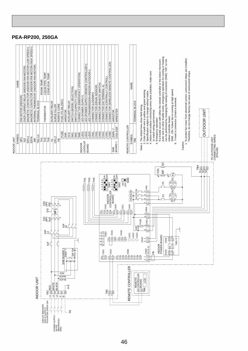
46
OU
TDO
OR
UN
IT
CIR
CU
IT B
RE
AK
ER
(FIE
LD S
UP
PLY
)P
EA
-RP
200,
250G
A:1
5A
DSR
DSA
(3P
)(H
i)
C02
(6P
)(L
o)C01
C01
54
TH5
TH2
TH1
IND
OO
R U
NIT
PO
WE
R S
UP
PLY
3N~P
E38
0/40
0/41
5V50
Hz
BLACKWHITE
RED
NB
LAC
KW
HIT
ER
ED
TB2
L3L2L1
PE
52F
Hi
Lo
321
52F
1 2 3
MF1
TB6
LCD
REM
OTE
CO
NTR
OLL
ER
FB
TB4
S3
S2
S1
X6
X5
X4
37
51
FAN
ZNR
FUS
E
41
23
SW
2O
FFO
N5
TAB
1
31C
NS
K
21C
N2S
DC
13.1V
CN
2D
CN
90
CN
22
CN
2L
CN
DK
CN
D
CN
32
CN
31
CN
5112
34
5
31
31
31
12
DC
13.1
V
LED
1
LED
2
LED
3
21 21 21
21 33 654 987
31 2
CN
3C
CN
20
CN
21
CN
41
CN
29
1 2 3 4 1 2 1 221
1 2
TB5
Hi
52F
Lo52F
X1
X1
X149
F51
F
X6
X5
X4
12
34
5
SW
1O
FFO
N
SW
EO
FFON
SW
ITC
H (M
OD
EL
SE
LEC
TIO
N)
SW
ITC
H (C
APA
CIT
Y C
OD
E)
CO
NN
EC
TOR
(EM
ER
GE
NC
Y O
PE
RAT
ION
)
SN
BB
OA
RD
1ZN
R5~
7VA
RIS
TOR
DS
A,D
SR
AR
RE
STE
R
IND
OO
R U
NIT
NA
ME
SY
MB
OL
CO
ND
./EVA
. TE
MP.
LI
QU
ID P
IPE
TE
MP.
RO
OM
TE
MP.
52FH
iM
AG
NE
TIC
CO
NTA
CTO
R (I
ND
OO
R F
AN
MO
TOR
<HIG
H S
PE
ED
>)
SU
RG
E K
ILLE
RC
R1,
2 SW
1
TH5
LED
(TR
AN
SM
ISS
ION
<IN
DO
OR
·OU
TDO
OR
>)LE
D3
LED
(PO
WE
R S
UP
PLY
<RE
MO
TE C
ON
TRO
LLE
R>)
LED
2LE
D (P
OW
ER
SU
PP
LY)
LED
1S
WE
SW
2
X4-
6A
UX
ILIA
RY
RE
LAY
VAR
ISTO
RZN
RFU
SE
(T6.
3AL2
50V
)FU
SE
THE
RM
ISTO
R
TER
MIN
AL
BLO
CK
INTE
RN
AL
THE
RM
OS
TAT
(IND
OO
R F
AN
MO
TOR
)
OV
ER
CU
RR
EN
T R
ELA
Y (IN
DO
OR
FA
N M
OTO
R)
FAN
MO
TOR
(IN
DO
OR
)
TH2
TH1
TB2,
4,5
49F
51F
MF1
52FL
oM
AG
NE
TIC
CO
NTA
CTO
R (I
ND
OO
R F
AN
MO
TOR
<LO
W S
PE
ED
>)
AU
XIL
IAR
Y R
ELA
YX
1
FER
RIT
E C
OR
EFB
BO
AR
DCO
NTRO
LLER
IND
OO
R
CN
2LC
N31
CN
90C
N51
CN
41C
N32
CO
NN
EC
TOR
(DR
AIN
SE
NS
OR
)C
ON
NE
CTO
R (R
EM
OTE
SW
ITC
H)
CO
NN
EC
TOR
(HA
TER
MIN
AL-
A)
CO
NN
EC
TOR
(CE
NTR
ALL
Y C
ON
TRO
L)C
ON
NE
CTO
R (W
IRE
LES
S R
EM
OTE
CO
NTR
OLL
ER
)
CO
NN
EC
TOR
(LO
SS
NAY
)
4. In
door
and
out
door
con
nect
ing
wire
s ha
ve p
olar
ities
, mak
e su
re
to
mat
ch w
iring
and
term
inal
.5.
Em
erge
ncy
oper
atio
n
If a
trou
ble
occu
rs w
ith e
ither
the
rem
ote
cont
rolle
r or t
he in
door
mic
roco
m-
p
uter
and
no
othe
r tro
uble
exi
sts,
em
erge
ncy
oper
atio
n fo
r coo
ling
or h
eatin
g
can
be
perfo
rmed
by
chan
ging
the
setti
ng o
f con
nect
or (S
WE
) "O
N" o
n th
e
ind
oor c
ontro
ller b
oard
.
SW
E :
ON
/ In
door
fan
is ru
nnin
g at
hig
h sp
eed.
TER
MIN
AL
BLO
CK
TB6
SY
MB
OL
RE
MO
TE C
ON
TRO
LLE
RN
AM
E
SN
B B
OA
RD
1
RE
MO
TECO
NTRO
LLER
BO
AR
D
PO
WE
R B
OA
RD
IND
OO
R
IND
OO
RC
ON
TRO
LLE
RB
OA
RD
Not
e:1.
The
dot
ted
lines
sho
w fi
eld
wiri
ng.
2
. Col
or o
f ear
th w
ire is
yel
low
and
gre
en tw
istin
g.
3. S
peci
ficat
ion
subj
ect t
o ch
ange
with
out n
otic
e.
51F
Cau
tion, 1. T
o pr
otec
t fan
mot
or fr
om a
bnor
mal
cur
rent
, ove
rcur
rent
rela
ys a
re in
stal
led.
Th
eref
ore,
do
not c
hang
e fa
ctor
y se
t val
ue o
f ove
rcur
rent
rela
ys.
6
.
mar
k is
con
nect
or.
mar
k is
term
inal
.CR
1CR
2
ZNR
5~7
TO O
UTD
OO
R U
NIT
CO
NN
EC
TIN
G W
IRE
S
(PO
LAR
)
PEA-RP200, 250GA
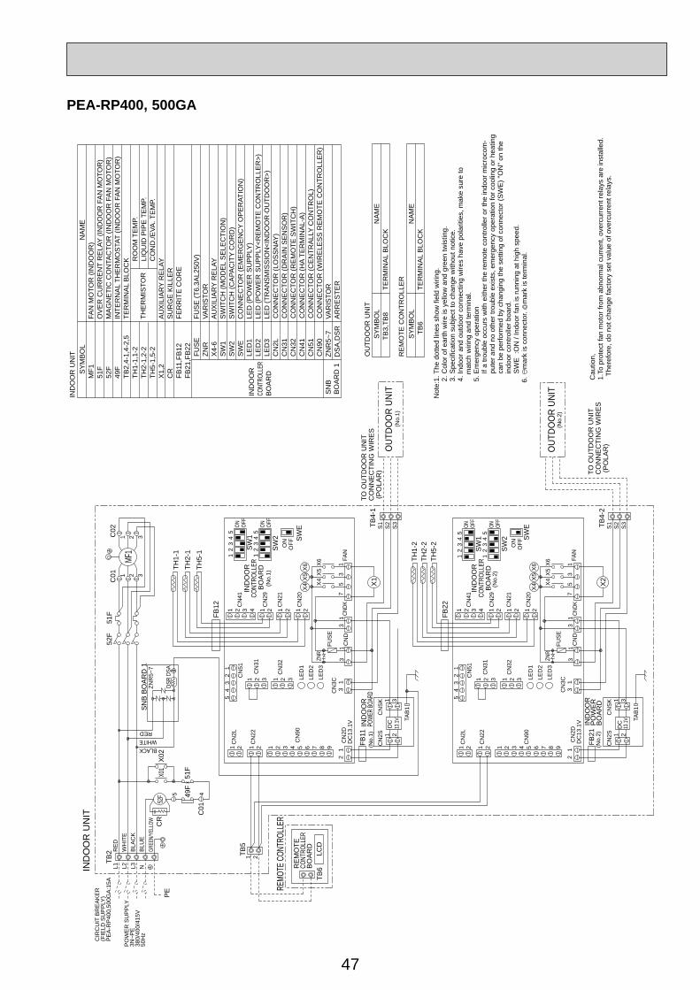
47
PEA-RP400, 500GA
GREE
N/YE
LLOW
IND
OO
R U
NIT
OUT
DOO
R UN
IT
OUT
DOO
R UN
IT
TAB
1
TAB
1
FAN
CNDK
31
15
73
X4
X5
X6
CN
20
CN
21
CN
41
CN
29
1 2 3 4 1 2 1 221
CN
2D
CN
90
CN
22
CN
2L
CN
D
CN
32
CN
31
CN
5112
34
5
FUS
E
ZNR
31
31
12
DC
13.1
V
LED
1LE
D2
LED
3
21 21 21
21 33 654 987
31 2
CN
3C
31C
NS
K
21C
N2S
DC
13.1V
31C
NS
K
21C
N2S
DC
13.1V
CN
2D
CN
90
CN
22
CN
2L
FAN
CNDK
CN
D
CN
32
CN
31
CN
5112
34
5
FUS
E
ZNR
31
31
31
12
DC
13.1
V1
57
3
X4
X5
X6
LED
1LE
D2
LED
3
21 21 21
21 33 654 987
31 2
CN
3C
CN
20
CN
21
CN
41
CN
29
1 2 3 4 1 2 1 221
FB11
S1
1 2
REMO
TE C
ONTR
OLLE
R
S2
S3
TB5
TB6
LCD
X1
FB21
S1
S2
S3
X2
TH1-
1TH
2-1
TH5-
1
TH5-
2TH
2-2
TH1-
2
TB4-
2
TB4-
1
FB12
FB22
X4
X5
X6
X4
X5
X6
51F
BLU
E
PO
WE
R S
UP
PLY
3N~P
E38
0/40
0/41
5V50
Hz
CIR
CU
IT B
RE
AK
ER
(FIE
LD S
UP
PLY
)P
EA
-RP
400,
500G
A:1
5A
BLACKWHITE
RED
DSR
DSA
NB
LAC
KW
HIT
ER
ED
TB2
L3L2L1
PE
52F
C01
C02
1 2 3
MF1
1 2 3
52F
C01
5 4
X01
X02
49F
SW
EO
FFON3
45
SW
1OF
FON
5ON OF
F
34
12 2
1
SW
EO
FFON34
5
SW
1OF
FON
5ON OF
FS
W2
34
12 2
1
SW
2
AU
XIL
IAR
Y R
ELA
YX
4-6
MF1
51F
49F
TB2,
4-1,
4-2,
5TH
1-1,
1-2
TH2-
1,2-
2
FAN
MO
TOR
(IN
DO
OR
)O
VE
R C
UR
RE
NT
RE
LAY
(IND
OO
R F
AN
MO
TOR
)
INTE
RN
AL
THE
RM
OS
TAT
(IND
OO
R F
AN
MO
TOR
)TE
RM
INA
L B
LOC
K
THE
RM
ISTO
R
IND
OO
R U
NIT FU
SE
FUS
E (T
6.3A
L250
V)
ZNR
VAR
ISTO
R
TH5-
1,5-
2
CR
SU
RG
E K
ILLE
R
MA
GN
ETI
C C
ON
TAC
TOR
(IN
DO
OR
FA
N M
OTO
R)
52F
RO
OM
TE
MP.
LIQ
UID
PIP
E T
EM
P.C
ON
D./E
VA. T
EM
P.
FER
RIT
E C
OR
EFB
11,F
B12
FB21
,FB
22
IND
OO
RCO
NTRO
LLER
BO
AR
DX1,
2A
UX
ILIA
RY
RE
LAY
NA
ME
SY
MB
OL
SN
BB
OA
RD
1ZN
R5~
7VA
RIS
TOR
DS
A,D
SR
AR
RE
STE
R
SW
2S
WE
LED
1LE
D (P
OW
ER
SU
PP
LY)
LED
2LE
D (P
OW
ER
SU
PP
LY<R
EM
OTE
CO
NTR
OLL
ER
>)LE
D3
LED
(TR
AN
SM
ISS
ION
<IN
DO
OR
·OU
TDO
OR
>)
SW
ITC
H (M
OD
EL
SE
LEC
TIO
N)
SW
1S
WIT
CH
(CA
PAC
ITY
CO
RD
)C
ON
NE
CTO
R (E
ME
RG
EN
CY
OP
ER
ATIO
N)
OU
TDO
OR
UN
IT
TER
MIN
AL
BLO
CK
NA
ME
SY
MB
OL
TB3,
TB8
CN
2LC
N31
CN
90C
N51
CN
41C
N32
CO
NN
EC
TOR
(DR
AIN
SE
NS
OR
)C
ON
NE
CTO
R (R
EM
OTE
SW
ITC
H)
CO
NN
EC
TOR
(HA
TER
MIN
AL-
A)
CO
NN
EC
TOR
(CE
NTR
ALL
Y C
ON
TRO
L)C
ON
NE
CTO
R (W
IRE
LES
S R
EM
OTE
CO
NTR
OLL
ER
)
CO
NN
EC
TOR
(LO
SS
NAY
)
RE
MO
TE C
ON
TRO
LLE
R
TER
MIN
AL
BLO
CK
NA
ME
SY
MB
OL
TB6
4. In
door
and
out
door
con
nect
ing
wire
s ha
ve p
olar
ities
, mak
e su
re to
mat
ch w
iring
and
term
inal
.5.
Em
erge
ncy
oper
atio
n
If a
trou
ble
occu
rs w
ith e
ither
the
rem
ote
cont
rolle
r or t
he in
door
mic
roco
m-
p
uter
and
no
othe
r tro
uble
exi
sts,
em
erge
ncy
oper
atio
n fo
r coo
ling
or h
eatin
g
can
be
perfo
rmed
by
chan
ging
the
setti
ng o
f con
nect
or (S
WE
) "O
N" o
n th
e
indo
or c
ontro
ller b
oard
.
SW
E :
ON
/ In
door
fan
is ru
nnin
g at
hig
h sp
eed.
(No.
2)
IND
OO
RCO
NTRO
LLER
BO
AR
D(N
o.1)
RE
MO
TECO
NTRO
LLER
BO
AR
D
IND
OO
RP
OW
ER
BO
AR
D
(No.
1)
(No.
2)
IND
OO
RCO
NTRO
LLER
BO
AR
D(N
o.2)
TO O
UTD
OO
R U
NIT
CO
NN
EC
TIN
G W
IRE
S (P
OLA
R) TO
OU
TDO
OR
UN
ITC
ON
NE
CTI
NG
WIR
ES
(PO
LAR
)
SN
B B
OA
RD
1
(No.
1)IN
DO
OR
POWE
R BOA
RD
Not
e:1.
The
dot
ted
lines
sho
w fi
eld
wiri
ng.
2. C
olor
of e
arth
wire
is y
ello
w a
nd g
reen
twis
ting.
3. S
peci
ficat
ion
subj
ect t
o ch
ange
with
out n
otic
e.
51F
6.
mar
k is
con
nect
or.
mar
k is
term
inal
.
Cau
tion,
1.To
pro
tect
fan
mot
or fr
om a
bnor
mal
cur
rent
, ove
rcur
rent
rela
ys a
re in
stal
led.
The
refo
re, d
o no
t cha
nge
fact
ory
set v
alue
of o
verc
urre
nt re
lays
.
CR
ZNR
5~7

48
PKA-RP35HAL PKA-RP50HAL
Terminal block (Remote controller transmission line) R.B
Symbol Name Symbol NameI.B Indoor controller board
FUSE FUSE(T3.15AL250V)
CN2L Connector (LOSSNAY)
CN90 Connector (Remote operation adapter)
Connector (Emergency operation)
CNP Drain pump (option) power supply (Drain pump (option))
CN4F Drain float switch (Drain pump (option))DCL REACTOR
CN32 Connector ( Remote switch)CN41 Connector (HA terminal-A)CN51 Connector (Centrally control)
LED1 Power supply (I.B)LED2 Power supply (R.B)LED3 Transmission (Indoor-outdoor)
X1 Relay (Drain pump (option))
SW1 Switch (Model selection) See table 1SW2SWE
Switch (Capacity code) See table 2
[Explanation of symbols]
MS Fan motor
W.B Pcb for wireless remote controller
Switch boardSWE2 Emergency operation
M Vane motor
LED1 LED (Operation indication : Green)
REC1 Receiving unitLED2 LED (Preparation for heating: Orange)
TB2 Terminal block(Indoor unit Power (option))TB4 Terminal block (Indoor/outdoor connecting line)TB5 Terminal block (Remote controller transmission line(option))TH1 Room temp. Thermistor
Pipe temp. Thermistor/liquid
Cond./eva. temp. Thermistor
(0 /15kΩ, 25 /5.4kΩ Detect)
(0 /15kΩ, 25 /5.4kΩ Detect)
(0 /15kΩ, 25 /5.4kΩ Detect)
TH2
TH5
S.W
Wired remote controller(option)TB6 DPDP DRAIN PUMP (OPTION)
DRAIN FLOAT SWITCH (OPTION)FS
Notes:1. SymboIs used in wiring diagram above are, : Connector, : Terminal (block).2. Indoor and outdoor connecting wires have poIarities, make sure to match terminal numbers (S1, S2, S3) for correct wirings.3. Since the outdoor side electric wiring may change, be sure to check the outdoor unit electric wiring diagram for servicing.4. This diagram shows the wiring of indoor and outdoor connecting wires. (specification of 230V), adopting superimposed system for power and signal. 1: If indoor and outdoor units have separate power supplies, refer to Fig. 1. 2: For power supply system of this unit, refer to the caution label located near this diagram.
TO OUTDOOR UNIT
531
31
CN01(BLK)
ORNYLW
BLURED
GRN/YLW
I.B1(Fig. 1)
I.B
POWER SUPPLY~(1PHASE)230V 50Hz
L
N
ORNORN
YLW
BRN
TB4
TB2
S1
S2
S3
INDOOR/OUTDOORCOMMUNICATIONCN3C(BLU)
Refer to tables1and 2
CN90(WHT)
CN2L(RED)
CN151(WHT)
CN20(RED)
CN44(WHT)
CN4F(WHT)
CN22(BLU)
CN41(WHT)
CN51(WHT)
CN32(WHT)
CNMF(WHT)
S.W
W.B
SWE
R.B
CNP(BLU)CN3C(BLU)
CNRU(WHT)
LDSWE(A)(BLU)
LDSWE(B)
LD101(B) REC1
LED1 LED2
SWE2
CN01(BLK)
T11 DB1
X1
FUSE
I.B1
1
1 1 1 5 64
1 112
1 4 1 425
TH1 TH2 TH5
2
11 39
3
3
3 2
21
21
1
1
5
6
Mt○ t○ t○
MS3~
M1~
TB4
TB5
S1S2S3
RU
BLUBLU
ORN
ORN
DP
ORN
BRN
LED1
LED3
LED2
(OPTION PARTS)
TB6
ONOFF
TOOUTDOORUNIT
YLW YLWYLW
DCL
BLK
<Table 1> SW1(MODEL SELECTION)
SETTING
SETTING
ONOFF
1 2 3 4 5
<Table 2> SW2 (CAPACITY CODE)MODELS
RP35 ONOFF
1 2 3 4 5
ONOFF
1 2 3 4 5RP50
FLOAT SWCN4F(WHT)
When attaching drain pump(option), remove the jumper connector CN4F and fit the drain float switch (FS).
When attaching drain pump (option)
FS
1 4
The black square (■) indicates a switch position.
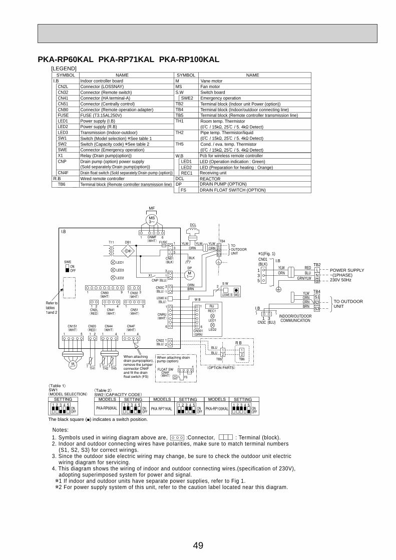
49
SYMBOL SYMBOLNAME NAMEI.B
R.B
Indoor controller board
FUSE (T3.15AL250V)
Connector (LOSSNAY)Connector (Remote switch)Connector (HA terminal-A)Connector (Centrally control)
Power supply (I.B)Power supply (R.B)Transmission (Indoor-outdoor)
Relay (Drain pump(option))
Switch (Model selection) See table 1Switch (Capacity code) See table 2Connector (Emergency operation)
Vane motorFan motor
DRAIN PUMP (OPTION)DRAIN FLOAT SWITCH (OPTION)
Terminal block (Indoor unit Power (option))Terminal block (Indoor/outdoor connecting line)Terminal block (Remote controller transmission line)
REACTOR
Room temp. Thermistor(0 / 15k , 25 / 5. 4k Detect)Pipe temp. Thermistor/liquid(0 / 15k , 25 / 5. 4k Detect)Cond. / eva. temp. Thermistor(0 / 15k , 25 / 5. 4k Detect)
M
FUSE
MSSwitch boardS.WEmergency operationSWE2
Drain pump (option) power supply(Sold separately:Drain pump(option))
CNP
DP
CN2L
FS
CN32
TB2CN41CN51
Connector (Remote operation adapter)CN90 TB4
DCL
LED1TB5
LED2TH1
LED3
X1
Drain float switch (Sold separately:Drain pump (option))CN4FWired remote controllerTerminal block (Remote controller transmission line)TB6
TH2SW1
TH5SW2SWE
[LEGEND]
TO OUTDOORUNIT
531
31
CN01(BLK)
ORNYLW
BLURED
GRN/YLW
I.B1(Fig. 1)
I.B
TB2POWER SUPPLY~(1PHASE)230V 50Hz
ORNORN
YLW
BRN
TB4
INDOOR/OUTDOORCOMMUNICATIONCN3C (BLU)
LN
S1S2S3
W.B
REC1
LED1LED2
Pcb for wireless remote controller
Receiving unit
LED (Operation indication : Green)LED (Preparation for heating : Orange)
1. SymboIs used in wiring diagram above are, :Connector, : Terminal (block).2. Indoor and outdoor connecting wires have poIarities, make sure to match terminal numbers (S1, S2, S3) for correct wirings.3. Since the outdoor side electric wiring may change, be sure to check the outdoor unit electric wiring diagram for servicing.4. This diagram shows the wiring of indoor and outdoor connecting wires.(specification of 230V), adopting superimposed system for power and signal. 1 If indoor and outdoor units have separate power supplies, refer to Fig 1. 2 For power supply system of this unit, refer to the caution label located near this diagram.
Notes:
MF
The black square (■) indicates a switch position.
PKA-RP60KAL PKA-RP71KAL PKA-RP100KAL
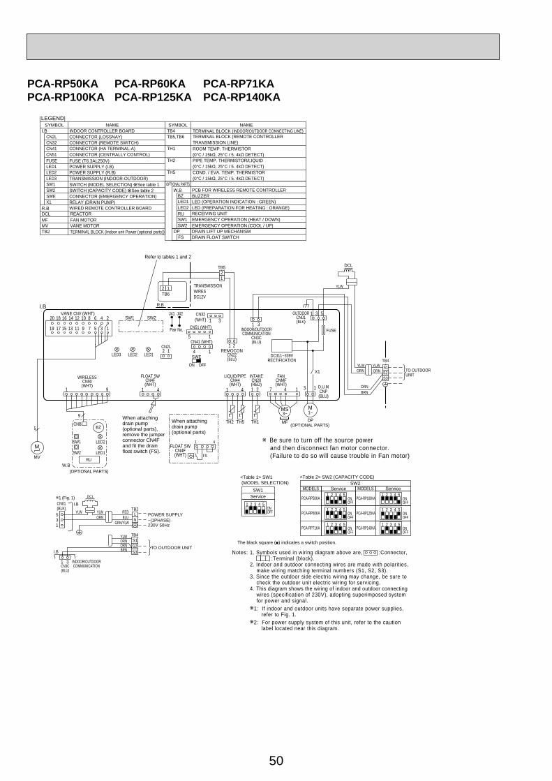
50
PCA-RP50KA PCA-RP60KA PCA-RP71KAPCA-RP100KA PCA-RP125KA PCA-RP140KA
DCL
TO OUTDOOR UNIT
135
31
CN01(BLK)
ORNYLW YLW
BLURED
GRN/YLW
I.B1 (Fig. 1)
I.B
TB2POWER SUPPLY~(1PHASE)230V 50Hz
ORNORN
YLW
BRN
TB4
INDOOR/OUTDOORCOMMUNICATIONCN3C
(BLU)
INDOOR/OUTDOORCOMMUNICATION
CN3C(BLU)
<Table 2> SW2 (CAPACITY CODE)
Service ServiceMODELSSW2
PCA-RP100KA
MODELS
ONOFF
1 2 3 4 5PCA-RP50KA ON
OFF
1 2 3 4 5
PCA-RP125KA ONOFF
1 2 3 4 5PCA-RP60KA ON
OFF
1 2 3 4 5
PCA-RP140KA ONOFF
1 2 3 4 5PCA-RP71KA ON
OFF
1 2 3 4 5
1 9
1
1
3
4
5 1
4 1
1
2
3
4
5
6
7
8
9
10
11
12
13
14
15
16
17
18
19
20
CN2L
ON OFF
SWE
J42J41SW2SW1
LED3 LED2 LED1
LED2
LED1RU
SW2
SW1
CNB
9
5
t° t° t°TH2 TH5 TH1
MV
BZ
M
W.B
TB6
R.BI.B
1 4
2 121
21
12
12
Refer to tables 1 and 2
TRANSMISSIONWIRESDC12V
TB4YLWORN
ORNBRN
YLW
YLW
ORN
DCL
TO OUTDOORUNIT
1 3 5
3 1
X1
M1~DP
D.U.MCNP(BLU)
FUSE
OUTDOORCN01(BLK)
DC311~339VRECTIFICATION
S1S2S3
7 4 1
3~
MF
MS
(OPTIONAL PARTS)
(OPTIONAL PARTS)
1 3
REMOCONCN22(BLU)
WIRELESSCN90(WHT)
VANE CNV (WHT)
Pair No.
FANCNMF(WHT)
INTAKECN20(RED)
FLOAT SWCN4F(WHT)
LIQUID/PIPECN44(WHT)
TB5
CN32(WHT)
CN51 (WHT)
CN41 (WHT)
<Table 1> SW1 (MODEL SELECTION)
SW1
ONOFF
1 2 3 4 5
Be sure to turn off the source power and then disconnect fan motor connector. (Failure to do so will cause trouble in Fan motor)
LN
S1S2S3
Service
SYMBOL SYMBOLNAME NAMEI.B
R.B
INDOOR CONTROLLER BOARD
FUSE (T6.3AL250V)
CONNECTOR (LOSSNAY)CONNECTOR (REMOTE SWITCH)CONNECTOR (HA TERMINAL-A)CONNECTOR (CENTRALLY CONTROL)
POWER SUPPLY (I.B)POWER SUPPLY (R.B)TRANSMISSION (INDOOR-OUTDOOR)
RELAY (DRAIN PUMP)WIRED REMOTE CONTROLLER BOARD
SWITCH (MODEL SELECTION) See table 1SWITCH (CAPACITY CODE) See table 2CONNECTOR (EMERGENCY OPERATION)
FAN MOTORVANE MOTOR
DRAIN LIFT UP MECHANISMDRAIN FLOAT SWITCH
TERMINAL BLOCK (Indoor unit Power (optional parts))
TERMINAL BLOCK (INDOOR/OUTDOOR CONNECTING LINE)TERMINAL BLOCK (REMOTE CONTROLLERTRANSMISSION LINE)
REACTOR
ROOM TEMP. THERMISTOR(0°C / 15kΩ, 25°C / 5. 4kΩ DETECT)PIPE TEMP. THERMISTOR/LIQUID(0°C / 15kΩ, 25°C / 5. 4kΩ DETECT)COND. / EVA. TEMP. THERMISTOR(0°C / 15kΩ, 25°C / 5. 4kΩ DETECT)
MF
FUSE
MVDP
CN2L
FS
CN32
TB2
CN41CN51
TB4
DCL
LED1
TB5,TB6
LED2
TH1
LED3
X1
TH2
SW1
TH5
SW2SWE
[LEGEND]
1. SymboIs used in wiring diagram above are, :Connector, :Terminal (block).2. Indoor and outdoor connecting wires are made with poIarities, make wiring matching terminal numbers (S1, S2, S3).3. Since the outdoor side electric wiring may change, be sure to check the outdoor unit electric wiring for servicing.4. This diagram shows the wiring of indoor and outdoor connecting wires (specification of 230V), adopting superimposed system for power and signal.
1: If indoor and outdoor units have separate power supplies, refer to Fig. 1.
2: For power supply system of this unit, refer to the caution label located near this diagram.
W.B
RU
BZLED1LED2
SW1SW2
OPTIONAL PARTSPCB FOR WIRELESS REMOTE CONTROLLER
RECEIVING UNIT
BUZZERLED (OPERATION INDICATION : GREEN)LED (PREPARATION FOR HEATING : ORANGE)
EMERGENCY OPERATION (HEAT / DOWN)EMERGENCY OPERATION (COOL / UP)
Notes:
FLOAT SWCN4F(WHT)
When attaching drain pump(optional parts), remove the jumper connector CN4F and fit the drain float switch (FS).
When attaching drain pump(optional parts)
FS
1 4
The black square (■) indicates a switch position.
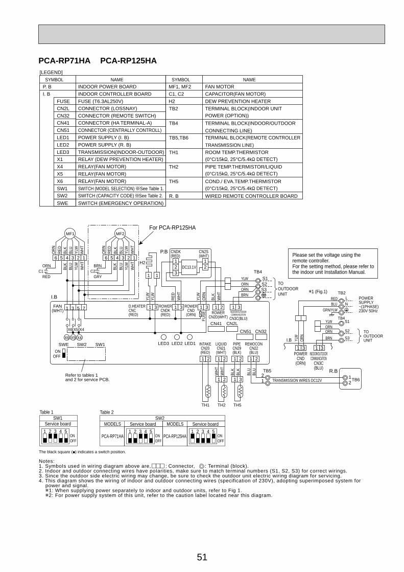
51
PCA-RP71HA PCA-RP125HA
SYMBOL[LEGEND]
NAME SYMBOL NAMEINDOOR POWER BOARDINDOOR CONTROLLER BOARDFUSE (T6.3AL250V)
MF1, MF2C1, C2H2
FAN MOTORCAPACITOR(FAN MOTOR)DEW PREVENTION HEATER
CONNECTOR (LOSSNAY)CONNECTOR (REMOTE SWITCH)CONNECTOR (HA TERMINAL-A)CONNECTOR (CENTRALLY CONTROLL)POWER SUPPLY (I. B)POWER SUPPLY (R. B)TRANSMISSION(INDOOR-OUTDOOR)RELAY (DEW PREVENTION HEATER)RELAY(FAN MOTOR)RELAY(FAN MOTOR)RELAY(FAN MOTOR)SWITCH (MODEL SELECTION) See Table 1.SWITCH (CAPACITY CODE) See Table 2.SWITCH (EMERGENCY OPERATION)
P. BI. B
FUSECN2LCN32CN41CN51LED1LED2LED3X1X4X5X6SW1
TB2
TB4
TB5,TB6
TH1
TH2
TH5
R. B
TERMINAL BLOCK(INDOOR UNIT POWER (OPTION))TERMINAL BLOCK(INDOOR/OUTDOORCONNECTING LINE)TERMINAL BLOCK(REMOTE CONTROLLERTRANSMISSION LINE)ROOM TEMP.THERMISTOR(0°C/15k , 25°C/5.4k DETECT)PIPE TEMP.THERMISTOR/LIQUID(0°C/15k , 25°C/5.4k DETECT)COND./ EVA.TEMP.THERMISTOR(0°C/15k , 25°C/5.4k DETECT)WIRED REMOTE CONTROLLER BOARDSW2
SWE
Service boardSW1
Table 1
1 2 3 4 5ONOFF
Service boardSW2
Table 2
1 2 3 4 5MODELS
PCA-RP71HA ONOFF
Service board1 2 3 4 5
MODELS
PCA-RP125HA ONOFF
MF1
BLU
BLK
WHT
YLW
BLU
BLK
WHT
YLW
ORN
ORNC1
RED
RED
1 3 1 3 1 3 1 2
12
12
3
1 3
1 1
6 5 4 3 2 1
MF2
BLU
YLW
YLW
ORN
BLK
RED
WHT
WHT
YLW
BLK
WHT
YLW
BLU
BLK
WHT
YLW
ORN
BRNC2
GRY
RED
6 5 4 3 2 1
D.HEATERCNC(RED)
For PCA-RP125HA
X6 X5 X4
X6 X5 X4
FUSE
SWE
FAN(WHT)
SW2 SW1 LED3 LED2 LED1
H2
OFFON
1 2 1 2 1 2
1 2 1 3
1 2
WHT
WHT
REMOCONCN22(BLU)
TH1 TH2 TH5
BLU
BLU
BLK
BLK
12
21
TB5
INTAKECN20(RED)
LIQUIDCN21(WHT)
PIPECN29(BLK)
R.BTB6TRANSMISSION WIRES DC12V
CN41 CN2L
CN32CN51
ROWERCNDK(RED)
ROWERCND
(ORN)
DC13.1V
CNDK(RED)
CN2S(WHT)
P.B
I.B BRN
YLWORNORN
S1S2S3
TB4
TOOUTDOORUNIT
ROWERCN2D(WHT)
INDOOR/OUTDOORCOMMUNICATION
CN3C(BLU)
Refer to tables 1and 2 for service PCB.
Please set the voltage using theremote controller.For the setting method, please refer to the indoor unit Installation Manual.
3131POWER
CND(ORN)
INDOOR/OUTDOORCOMMUNICATION
CN3C(BLU)
TB4
POWERSUPPLY~(1PHASE)230V 50Hz
REDTB2
BLU
TO OUTDOORUNIT
L
S1
S2
S3
N
I.B YLW
ORN
ORNORN
YLW
GRN/YLW
BRN
1 (Fig.1)
1 3 5 7
Notes:1. SymboIs used in wiring diagram above are, : Connector, : Terminal (block).2. Indoor and outdoor connecting wires have poIarities, make sure to match terminal numbers (S1, S2, S3) for correct wirings.3. Since the outdoor side electric wiring may change, be sure to check the outdoor unit electric wiring diagram for servicing.4. This diagram shows the wiring of indoor and outdoor connecting wires (specification of 230V), adopting superimposed system for power and signal. 1: When supplying power separately to indoor and outdoor units, refer to Fig 1. 2: For power supply system of this unit, refer to the caution label located near this diagram.
The black square (■) indicates a switch position.
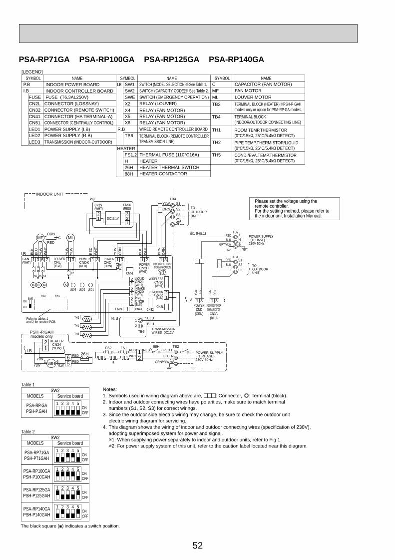
52
PSA-RP71GA PSA-RP100GA PSA-RP125GA PSA-RP140GA
1 3 5 7
MFORN
CRED
BLK
BLU
YLW
1 3 1 3 1 3 1 2
12
21
3
1 3
ML
YLW
YLW
BLK
OR
N
YLW
YLWORN
S1S2S3
WH
T
WH
T
WH
T
BR
NO
RN
RE
D
I.BFAN(WHT)
LOUVERCNL(YLW)
X4X5X6
X6 X5 X4
X2
FUSE
X2LED3 LED2 LED1
SWEON
OFF
POWERCNDK(RED)
POWERCND(ORN) POWER
CN2D(WHT)
WIRELESSCN90(WHT)
21
REMOCONCN22
(BLU)
CN32CN2L
21
TB6
2
21
121
LIQUIDCN21(WHT)INTAKECN20(RED)PIPECN29(BLK)
CN24 CN41
CN51
R.B
TRANSMISSIONWIRES DC12V
BLUBLUTH1
TH2
TH5
SW1SW2
TB4
REDRED
WHT
RED
BLUGRN/YLW
88HFS1FS2
H
5 312
L
N
TB2
POWER SUPPLY~(1 PHASE)230V 50Hz
21
65
RED
REDYLW
26H
88HYLW
YLW1 6
HEATERCN24(YLW)
I.B
PSH -P.GAHmodels only
INDOOR UNIT
The black square (■) indicates a switch position.
Please set the voltage using theremote controller.For the setting method, please refer to the indoor unit Installation Manual.
INDOOR/OUTDOORCOMMUNICATION
CN3C(BLU)
Refer to tables 1and 2 for service PCB.
P.B
CNSK(RED)
CN2S(WHT)
DC13.1V
TO OUTDOORUNIT
3131POWER
CND(ORN)
INDOOR/OUTDOORCOMMUNICATION
CN3C(BLU)
TB2
TB4
POWER SUPPLY~(1PHASE)230V 50Hz
REDBLU
GRY/YLW
REDBLU TO
OUTDOORUNIT
L
S1S2S3
N
I.B
YLW
ORN
ORN
BRN
1 (Fig.1)
Service boardSW2
Table 2
1 2 3 4 5MODELS
PSA-RP71GAPSH-P71GAH
PSA-RP100GAPSH-P100GAH
PSA-RP125GAPSH-P125GAH
PSA-RP140GAPSH-P140GAH
ONOFF
1 2 3 4 5ONOFF
1 2 3 4 5ONOFF
1 2 3 4 5ONOFF
Service boardSW2
Table 1
1 2 3 4 5MODELS
PSA-RP.GAPSH-P.GAH
ONOFF
P.B INDOOR POWER BOARDSYMBOL NAME
[LEGEND]SYMBOL NAME SYMBOL NAME
I.BI.B
INDOOR CONTROLLER BOARDFUSE FUSE (T6.3AL250V)CN2L CONNECTOR (LOSSNAY)CN32 CONNECTOR (REMOTE SWITCH)CN41 CONNECTOR (HA TERMINAL-A)CN51 CONNECTOR (CENTRALLY CONTROL)
SW1 SWITCH (MODEL SELECTION) See Table 1.SW2 SWITCH (CAPACITY CODE) See Table 2.SWE SWITCH (EMERGENCY OPERATION)
X4 RELAY (FAN MOTOR)X5 RELAY (FAN MOTOR)X6 RELAY (FAN MOTOR)
X2 RELAY (LOUVER)
POWER SUPPLY (R.B)LED1 POWER SUPPLY (I.B)LED2
TRANSMISSION (INDOOR-OUTDOOR)LED3
WIRED REMOTE CONTROLLER BOARDTERMINAL BLOCK (REMOTE CONTROLLERTRANSMISSION LINE)
R.BTB6
HEATER
HEATERTHERMAL FUSE (110°C16A)
HFS1,2
HEATER THERMAL SWITCH26HHEATER CONTACTOR88H
C CAPACITOR (FAN MOTOR) FAN MOTORMFLOUVER MOTORML
TB2
TERMINAL BLOCK(INDOOR/OUTDOOR CONNECTING LINE)
TB4
TERMINAL BLOCK (HEATER) PSH-P·GAH models only or option for PSA-RP·GA models.
ROOM TEMP.THERMISTOR(0°C/15k , 25°C/5.4k DETECT)PIPE TEMP.THERMISTOR/LIQUID(0°C/15k , 25°C/5.4k DETECT)COND./EVA.TEMP.THERMISTOR(0°C/15k , 25°C/5.4k DETECT)
TH1
TH2
TH5
Notes:1. SymboIs used in wiring diagram above are, : Connector, : Terminal (block).2. Indoor and outdoor connecting wires have poIarities, make sure to match terminal numbers (S1, S2, S3) for correct wirings.3. Since the outdoor side electric wiring may change, be sure to check the outdoor unit electric wiring diagram for servicing.4. This diagram shows the wiring of indoor and outdoor connecting wires (specification of 230V), adopting superimposed system for power and signal.
1: When supplying power separately to indoor and outdoor units, refer to Fig 1.2: For power supply system of this unit, refer to the caution label located near this diagram.

53
4-2. OUTDOOR UNITPUHZ-RP35VHA4 PUHZ-RP50VHA4
1 2 3 4 5 6 7 8
1 2 3 4 5 6 7 8
OFFON
35V
MODEL SW6
*1MODEL SELECTSW5-6 *2
OFFON
OFFON
50V OFFON
1 2 3 4 5 6
1 2 3 4 5 6
*2. SW5 -1 to 5 : Function Switch
P. B.
C. B.
CNF1(WHT)MF1
MS3~
71
TRANSCNDC(PNK)
3
1
TH7/6(RED)
63H(YLW)
TH3(WHT)
TH4(WHT)
TH7 TH6 TH3 TH4
41 21TH33(YLW)
TH33
1 3 2 1
31
t°t°t°t°t° t°
TH32(BLK)
TH32
21
63H
LEV-A(WHT)
LEV-A
LEV-B(RED)
LEV-B
61
M M
LED
1
LED
2
61CNVMNT(WHT)
31
CNDM
(WHT
)CN
51(W
HT)
31
5
1
CNMNT(WHT)
CNM(WHT)
51
35
SW7
SW6
SW1 SW
9CN31
1
*1*1
SW5
SW8
SW4
SWP
14
X51
CNS(WHT)
CNAC(WHT)
SS(WHT)
21S4(GRN)
X52
F1
F2
F4
F3
21
43
21S4
3 1
13 13
CN4(WHT)
1 2
2
CN52C(RED)
2
2
1CN2
(WHT)71
5
CN5
(WHT
)
3 1
LED2
SW1
SW11
SW12LED3LED4
TB7
LED1
LED5
21 CND
(WHT)CN2M
(WHT
)
M-NET ADAPTER
M-NET
A B S
When M-NET adapter is connected
5
3
5
1
WHT
U U
LI EI NI
LO NO
E2E3
N. F.
1 2
2
3
1
3
1
1
22
CN5
(RED
)
CNAC
1(W
HT)
CNAC
2(R
ED)
CN52
C(B
LK)
BLK
BLK
52C
RED
POWER SUPPLY~/N 230V 50Hz
INDOORUNIT
TB1L N S1 S2 S3
RED
BLU
BLK
YLW
GRN/
YLW
ORN
BRN
CY2CY1
CB1 CB2 CB3
TABUTABV
TH8
IPM
TABW
TABR
TABS
CN3(WHT)
CN2(WHT)
CN4(WHT)
CN5(RED)
1
7
12
12
12
2
2
5
t°WHTRED
PFC
RED
WHT
RED
WHT
ACL
MS3~
BLK
WHT
RED
UVW
MC
TB1MCMF121S463HTH3, TH33TH4TH6TH7TH8
LEV-A, LEV-BACL
Terminal Block<Power Supply, Indoor/Outdoor>Motor for CompressorFan Motor Solenoid Valve (Four-Way Valve)High Pressure SwitchThermistor<Outdoor Pipe>Thermistor<Discharge>Thermistor<Outdoor 2-Phase Pipe>Thermistor<Outdoor>Thermistor<Heat Sink>
TH32 Thermistor<Shell>Electronic Expansion ValveReactor
CY1,CY2 ReactorPower Circuit Board
Connection Terminal<U/V/W-Phase>
P.B.
TABU/V/W
Noise Filter Circuit BoardConnection Terminal<L-Phase>
Connection Terminal<Ground>
N.F.LI/LO
Connection Terminal<N-Phase>NI/NOEI,E2,E3
Controller Circuit BoardSwitch<Forced Defrost, Defect History
Record Reset, Refrigerant Address>Switch<Test Operation>Switch<Function Switch>
Switch<Function Setup>
Switch<Pump Down>
SW1
SW4SW5
SW7Switch<Function Setup>SW8
SWP
CN51
CNM
CNVMNT
CNDM
LED1,LED2 LED<Operation Inspection Indicators>
Connector<A-Control Service Inspection Kit>
Connector<Connected to Optional M-NET Adapter Board>Connector< Connected for Option (Contact Input)>
C.B.
ConverterPFCPower ModuleIPM
Main Smoothing CapacitorCB1~CB3
52C Relay52C
SYMBOL NAME SYMBOL NAME SYMBOL NAME
Connection Terminal<L/N-Phase>TABR/S
CNMNT Connector<Connected to Optional M-NET Adapter Board>
Switch<Model Select>SW6
Connector<Emergency Operation>CN31
SwitchSW9
Fuse<T6.3AL250V>F1~4
X51,X52 Relay
SS Connector<Connection for Option>Connector<Connection for Option>
SYMBOLM-NET ADAPTER
NAMETB7CN5CNDCN2MSW1SW11
Terminal Block<M-net connection>Connector<Transmission>Connector<Power Supply>Connector<M-NET communication>Switch<Status of communication>Switch<Address setting : 1s digit>
SYMBOL NAMESW12LED1LED2LED3LED4LED5
Switch<Address setting : 10s digit>LED<Power Supply : DC5V>LED<Connection to Outdoor Unit>LED<Transmission : Sending>LED<Transmission : Recelving>LED<Power Supply : DC12V>
The black square (■) indicates a switch position.
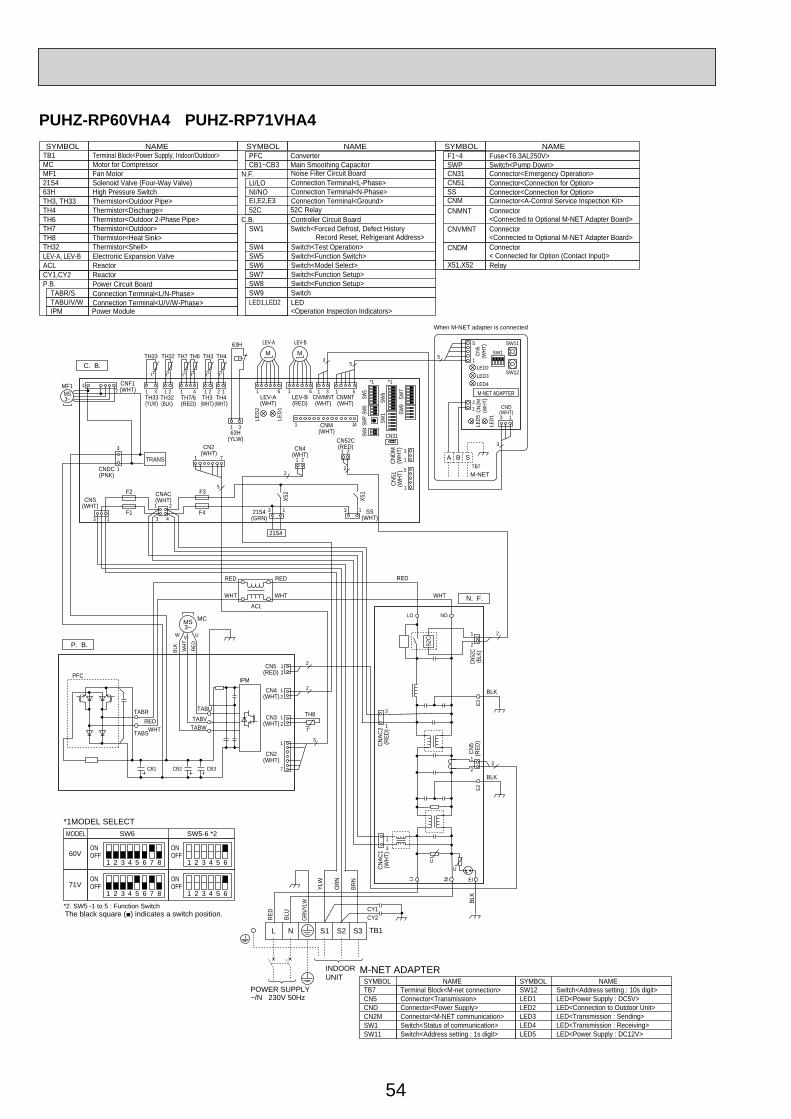
54
PUHZ-RP60VHA4 PUHZ-RP71VHA4
1 2 3 4 5 6 7 8
MODEL SW6
*1MODEL SELECTSW5-6 *2
OFF1 2 3 4 5 6
OFFON
60VON
1 2 3 4 5 6 7 8
*2. SW5 -1 to 5 : Function Switch
OFF1 2 3 4 5 6
OFFON
71VON
P. B.
C. B.
CNF1(WHT)MF1
MS3~
71
TRANSCNDC(PNK)
3
1
TH7/6(RED)
63H(YLW)
TH3(WHT)
TH4(WHT)
TH7 TH6 TH3 TH4
41 21TH33(YLW)
TH33
1
t° t° t° t° t° t°
3 2 1
31
TH32(BLK)
TH32
21
63H
LEV-A(WHT)
LEV-A
LEV-B(RED)
LEV-B
61
M M
LED
1
LED
2
61CNVMNT(WHT)
31CN
DM(W
HT)
CN51
(WHT
)
31
5
1
CNMNT(WHT)
CNM(WHT)
51
35
SW7
SW6
SW1 SW
9
CN31
1
*1*1
SW5
SW8
SW4
SWP
14
X51
CNS(WHT)
CNAC(WHT)
SS(WHT)
21S4(GRN)
X52
F1
F2
F4
F3
21
43
21S4
3 1
13 13
CN4(WHT)
1 2
2
CN52C(RED)
2
2
1CN2
(WHT)71
5
CN5
(WHT
)
3 1
LED2
SW1
SW11
SW12LED3LED4
TB7
LED1
LED5
21 CND
(WHT)CN2M
(WHT
)
M-NET ADAPTER
M-NET
A B S
When M-NET adapter is connected
5
3
5
1
WHT
UU
LI EINI
LO NO
E2E3
N. F.
1 2
2
3
1
3
1
1
22
CN5
(RED
)
CNAC
1(W
HT)
CNAC
2(R
ED)
CN52
C(B
LK)
52C
RED
POWER SUPPLY~/N 230V 50Hz
INDOORUNIT
TB1L N S1 S2 S3
RED
BLU
BLK
BLK
BLK
YLW
GRN/
YLW
ORN
BRN
CY2CY1
CB1 CB2 CB3
TABUTABV
TH8
IPM
TABW
TABR
TABS
CN3(WHT)
CN2(WHT)
CN4(WHT)
CN5(RED)
1
7
12
12
12
2
2
5
t°WHTRED
PFC
RED
WHT
RED
WHT
ACL
MS3~
BLK
WHT
RED
UVW
MC
TB1MCMF121S463HTH3, TH33TH4TH6TH7TH8
LEV-A, LEV-BACL
Terminal Block<Power Supply, Indoor/Outdoor>Motor for CompressorFan Motor Solenoid Valve (Four-Way Valve)High Pressure SwitchThermistor<Outdoor Pipe>Thermistor<Discharge>Thermistor<Outdoor 2-Phase Pipe>Thermistor<Outdoor>Thermistor<Heat Sink>
TH32 Thermistor<Shell>Electronic Expansion ValveReactor
CY1,CY2 ReactorPower Circuit Board
Connection Terminal<U/V/W-Phase>
P.B.
TABU/V/W
Noise Filter Circuit BoardConnection Terminal<L-Phase>
Connection Terminal<Ground>
N.F.LI/LO
Connection Terminal<N-Phase>NI/NOEI,E2,E3
Controller Circuit BoardSwitch<Forced Defrost, Defect History
Record Reset, Refrigerant Address>Switch<Test Operation>Switch<Function Switch>
Switch<Function Setup>
Switch<Pump Down>
SW1
SW4SW5
SW7Switch<Function Setup>SW8
SWP
CN51
CNM
CNVMNT
CNDM
LED1,LED2 LED<Operation Inspection Indicators>
Connector<A-Control Service Inspection Kit>
Connector<Connected to Optional M-NET Adapter Board>Connector< Connected for Option (Contact Input)>
C.B.
Main Smoothing CapacitorCB1~CB3
52C Relay52C
SYMBOL NAME SYMBOL NAME SYMBOL NAME
Connection Terminal<L/N-Phase>TABR/S
CNMNT Connector<Connected to Optional M-NET Adapter Board>
Switch<Model Select>SW6
Connector<Emergency Operation>CN31
SwitchSW9
X51,X52 Relay
SS Connector<Connection for Option>Connector<Connection for Option>
SYMBOLM-NET ADAPTER
NAMETB7CN5CNDCN2MSW1SW11
Terminal Block<M-net connection>Connector<Transmission>Connector<Power Supply>Connector<M-NET communication>Switch<Status of communication>Switch<Address setting : 1s digit>
SYMBOL NAMESW12LED1LED2LED3LED4LED5
Switch<Address setting : 10s digit>LED<Power Supply : DC5V>LED<Connection to Outdoor Unit>LED<Transmission : Sending>LED<Transmission : Receiving>LED<Power Supply : DC12V>
Fuse<T6.3AL250V>F1~4ConverterPFC
Power ModuleIPM
The black square (■) indicates a switch position.

55
PUHZ-RP100VKA PUHZ-RP125VKA PUHZ-RP140VKA
1 2 3 4 5 6 7 8
1 2 3 4 5 6 7 8
1 2 3 4 5 6 7 8
OFFON
100V
MODEL SW6
*1. MODEL SELECT
*2. SW5 -1 to 5 : Function Switch
SW5-6 *2
OFFON
OFFON
125V OFFON
OFF
1 2 3 4 5 6
1 2 3 4 5 6
1 2 3 4 5 6OFF
ON140V
ON
SYMBOLM-NET ADAPTER
NAMETB7CN5CNDCN2MSW1SW11SW12LED1LED2LED3LED4LED5
Terminal Block<M-net connection>Connector<Transmission>Connector<Power Supply>Connector<M-NET communication>Switch<Status of communication>Switch<Address setting : 1s digit>Switch<Address setting : 10s digit>LED<Power Supply : DC5V>LED<Connection to Outdoor Unit>LED<Transmission : Sending>LED<Transmission : Recelving>LED<Power Supply : DC12V>
CN5(WHT)
3 1
LED2
SW1
SW11
SW12LED3LED4
TB7
LED1
LED5
2
1CND
(WHT)
CN2M(WHT)
M-NET ADAPTER
M-NET
A B S
When M-NET adapter is connected
CNVMNT(WHT)
31
CNDM
(WHT
)CN
51(W
HT)
31
5
1
CNMNT(WHT)
CNM(WHT)
51LEV-A(WHT)
LEV-A
C. B.
LEV-B(RED)
LEV-B
6
35
1TH7/6(RED)
63H(YLW)
TRANS
X51
TH3(WHT)
CNDC(PNK)
CNF1(WHT)
CNF2(WHT)
TH4(WHT)
TH7 TH6 TH3 TH4
41 21TH33(YLW)
TH33
3
t° t° t° t° t° t°
1 2 1
SW7
SW6
SW1 SW
9
CN31
141
MF1
MF2
MS3~
M M
MS3~
71
CN2(WHT)
CNS(WHT)
CNAC(WHT)
CN4(WHT)
SS(WHT)
21S4(GRN)
21
LED
1
LED
2
X52
F1
F2
F4
F3
*1*1
21
43
SW5
SW8
SW4
SWP
21S4
61
317
1
3
1
2
3 1
71
7
2
TH32(BLK)
TH32
21
13 13
CN52C(RED)
3
3
1
63H
5
3
5
15
LEV-C(BLU)
61
LEV-CRP140 only
M
5
DCL2
IGBT
N2
P2
MS3~
U
U
V
V
W
W
CN2(WHT)
CN4(WHT)
1 71 2
2
P. B.
CNDC(PNK)
BLK
WHT
U
CY1CY2
LINIEI
E4
E2
E3
U
POWER SUPPLY~/N 230V 50Hz
INDOORUNIT
TB1L N S1 S2 S3
MC
3
1
3
1
2
RED
CNAC1(WHT)
CNAC2(RED)
1 3
13
CN52C(RED)
52C
52C
BLU
YLW
GRN
/YLW O
RN
BRN
RED
WHT
RED
BLK BLK
BLK
BLK
DCL1
DCL
CB
TB1MCMF1, MF221S463HTH3, TH33TH4TH6TH7
DCL
Terminal Block<Power Supply, Indoor/Outdoor >Motor for CompressorFan Motor Solenoid Valve (Four-Way Valve)High Pressure SwitchThermistor<Outdoor Pipe>Thermistor<Discharge>Thermistor<Outdoor 2-Phase Pipe>Thermistor<Outdoor>
TH32 Thermistor<Shell>Electronic Expansion ValveReactor
CB Main Smoothing CapacitorCY1,CY2 Capacitor
Controller Circuit BoardC.B.
SYMBOL NAME SYMBOL NAME SYMBOL NAME
Switch<Function Setup>
Switch<Forced Defrost, Defect History Record Reset, Refrigerant Address>Switch<Test Operation>Switch<Function Switch>Switch<Model Select>
SW7
SW1
SW4SW5SW6
Switch<Function Setup>SW8
Switch<Pump Down>SWPConnector<Emergency Operation>CN31
LED1, LED2F1~F4
LED<Operation Inspection Indicators>
CN51
CNMCNMNT
CNVMNT
CNDM
Connector<A-Control Service Inspection Kit>Connector<Connected to Optional M-NET Adapter Board>Connector<Connected to Optional M-NET Adapter Board>Connector< Connected for Option (Contact Input)>
Fuse< T6.3AL250V>X51,X52 Relay
SS Connector<Connection for Option>Connector<Connection for Option>
LEV-A, LEV-B, LEV-C
Power Module
N2 Connection TerminalConnection Terminal<Reactor>
Connection Terminal<Ground>
DCL1,DCL2IGBTEI,E2,E3,E4
P.B. Power Circuit BoardConnection Terminal<U/V/W-Phase>
P2 Connection TerminalNI Connection Terminal<N-Phase>LI Connection Terminal<L-Phase>
U/V/W SwitchSW9
The black square (■) indicates a switch position.
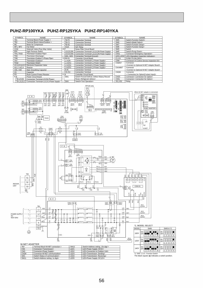
56
PUHZ-RP100YKA PUHZ-RP125YKA PUHZ-RP140YKA
TB1
MCMF1, MF221S463HTH3, TH33TH4TH6TH7
LEV-A,LEV-B,LEV-CACL1~ACL4
Terminal Block<Power Supply >
TB7 Terminal Block<M-NET connection >CN5 Connector<Transmission>CND Connector<Power Supply>CN2M Connector<M-NET communication>SW1 Switch<Status of communication>SW11 Switch<Address setting: 1s digit>
SW12 Switch<Address setting. 10s digit >LED1 LED<Power Supply: DC5V>LED2 LED<Connection to Outdoor Unit>LED3 LED<Transmission: Sending>LED4 LED<Transmission: Receiving>LED5 LED<Power Supply: DC12V>
TB2 Terminal Block<Indoor/Outdoor >Motor for CompressorFan Motor Solenoid Valve (Four-Way Valve)High Pressure SwitchThermistor<Outdoor Pipe>Thermistor<Discharge>Thermistor<Outdoor 2-Phase Pipe>Thermistor<Outdoor>
TH32 Thermistor<Shell>Electronic Expansion ValveReactor
RS Rush Current Protect Resistor
X52A 52C Relay
CB1, CB2 Main Smoothing CapacitorCK Capacitor
Power Circuit BoardConnection Terminal<U/V/W-Phase>
P.B.TB-U/V/W
Noise Filter Circuit BoardConnection Terminal<L1/L2/L3/N-Power Supply>
N.F.LI1/LI2/LI3/NI
Connection Terminal<L1/L2/L3/N-Power Supply>LO1/LO2/LO3/NO
Controller Circuit Board
Connector<Emergency Operation>
Switch<Function Setup>SW8
CN31
C.B.
Connection TerminalN-INConnection TerminalCK-OU
Connection Terminal<Ground>GD1, GD3
Connection Terminal<L1-Power Supply>L1-A1/IN
SYMBOL
M-NET ADAPTER
NAME SYMBOL NAME SYMBOL NAMEConnection TerminalTB-P2
Connection Terminal<L1/L2/L3-Power Supply>TB-L1/L2/L3
SwitchSW9Switch<Pump Down>SWP
Connection Terminal<L1-Power Supply>L1-A2/OUConnection Terminal<L2-Power Supply>L2-A2/OUConnection Terminal<L3-Power Supply>L3-A2/OU
Converter Circuit BoardCONV.B.
Switch<Forced Defrost, Defect History Record Reset, Refrigerant Adress>
SW1
Switch<Model Select>SW6Switch<Function Setup>SW7
Switch<Test Operation>SW4
LED1,LED2 LED<Operatiion Inspection Indicators>
CNMCNMNT
CNVMNT
Connector<A-Control Service Inspection Kit>Connector<Connect to Optional M-NET Adapter Board>Connector<Connect to Optional M-NET Adapter Board>
CN3S Connector< Connection for Option>
CNDM Connector< Connection for Option(Contact Input)>
CN51 Connector< Connection for Option>X51,X52 Relay
FUSE<T6.3AL250V>F1~F4
Connection TerminalTB-C1Connection TerminalTB-N1
Switch<Function Switch>SW5
LEV-A(WHT)
61
3
LEV-B(RED)
61CNVMNT
(WHT)
CN4(WHT)
CNMNT(WHT)
31 51
CN5
(WHT
)
3 1
LED2
SW1SW11
SW12LED3LED4
TB7
LED
1
LED5
5
1
2
5
1 CND(WHT)CN
2M(W
HT)
M-NET
When M-NET adapter is connected
71
21
21
1 2
3 4
CNS(WHT)
13 21S4(GRN)
MF1
TRANS
MF2
CNF1(WHT)
CNF2(WHT)
1
3
CNDC(PNK)
CN2(WHT)
CNAC(WHT) X5
1
X52
13 SS(WHT)
+
--
--
+
+ +
++
ACL1
ACL2
ACL3
ACL4
CN7(WHT)
CN2(WHT)
TB-P2
CB1 CB2 CK
TB-C1
L3-O
U
L2-O
U
L1-O
U
L3-A
2
L2-A
2
L1-A
2
L1-A
1
L1-IN N-IN
CK-O
U
TB-N1
TB-W BLKWHT
RED
BLKWHT
RED
BLK
BLU
WHT
RED
RED
RED
RED
RED
BLK
BLK
BLK
WHT
BRN
BLU
GRN/YLW
WHT
RED
TB-V
TB-U
TB-L3TB-L2
TB-L1
WVU
MC
CN4(WHT)
BLK
BLU
CNAC1(WHT)
CN7
(WHT
)W
HT
WHT
CN5(RED)
CNCT(RED)
CNAC2(RED)
CNL(BLU)
CNDC(PNK)
RS
P . B .
C . B .
N . F .
CONV.B.
LO1
GD1 GD3
LO2
LO3
NO
LI1
LI2
LI3
NI
TB1
TB2
POWER SUPPLY3N~400V 50Hz
INDOORUNIT
1
F2
F1
F3
F4
TH7/6(RED)
63H(YLW)
TH3(WHT)
TH4(WHT)
TH7 TH6 TH3 TH4
41 21TH33(YLW)
TH33
3
t° t° t° t° t° t°
1 2 1
31
TH32(BLK)
TH32
21
63H
2
2
1
7
2 3
1 2 3 4 5 6 7 8
1 2 3 4 5 6 7 8
1 2 3 4 5 6 7 8
OFFON
100Y
MODEL SW6*1. MODEL SELECT
*2. SW5 -1 to 5 : Function Switch
SW5-6 *2
OFFON
OFFON
125Y OFFON
OFF
1 2 3 4 5 6
1 2 3 4 5 6
1 2 3 4 5 6OFF
ON140Y
ON
3 7
RED
WHT BLK
71
71
71
REDX52A
RED
3 3
1
3121
LEV-A LEV-B
M M
LED
1
LED
2
CNM(WHT)
1 14
3131
5
1
35
CNDM
(WHT
)CN
3S(W
HT)
CN51
(WHT
)SW
7
SW6
SW1 SW
9
CN31
*1*1
SW5
SW8
SW4
SWP
21S4
A B S
MS3~
++
--1331
31
UU
U
U
U
L1
L2
L3
N
S1
S2
S3
YLW
ORN
BRN
31
MS3~
MS3~
2
2
2
2
M-NET ADAPTER
BLK
BLK
BLK
BLU
U
5
LEV-C(BLU)
61
LEV-CRP140 only
M
5
The black square (■) indicates a switch position.

57
PUHZ-RP200YKA PUHZ-RP250YKA
TH7/6(RED)
TH3(WHT)
TH4(WHT)
TH7 TH6 TH3 TH4
41 21 2 1TH32(BLK)
TH32
21
t° t° t° t° t°
LEV-B(RED)
LEV-B
M
LED1
LED2
61LEV-A(WHT)
LEV-A
M
61CNVMNT
(WHT)
31CNMNT(WHT)
CNM(WHT)
51
3 5
5
141
63H1
63H(YLW)
31
63H 63H2
CN2(WHT) 7
7
1
CN2(WHT)
77
1
CNDM
(WHT
)CN
3S(W
HT)
CN51
(WHT
)
1
3
1
3
1
5X51
X52
SW7
SW6
SW1 SW
9
CN31
*1*1
*3.For RP200
*3.For RP250
SW5
SW8
SW4
SWP
CN4(WHT)
1 2
1313
2
21S4
SS(WHT)
21S4(GRN)
CNAC(WHT)
F4
F3
21
43
2
3
1CNDC(PNK)
CNS(WHT)
3 1
TRANS
CNF1(WHT)
CNF2(WHT)
MF1MS3~
71
71MF2
MS3~
C. B.
P. B.CN
5(W
HT)
3 1
LED2
SW1
SW11
SW12LED3
LED4
TB7
LED1
LED5
21 CND
(WHT)CN2M
(WHT
)
M-NET ADAPTER
M-NET
A B S
When M-NET adapter is connected
3
5
1
22
122
1
CN4(WHT)CN5
(RED)
WHT
FUSE
1
FUSE
2
WHT
RED
RED
MS3~
POWERSUPPLY3N~400V 50Hz
INDOORUNIT
TB1
L3
L2
L1
N U
U
UU
U
31
2
2
13CNDC(PNK)
CNL(BLU)
311 2CNCT(RED)
CNAC2(RED)31
CNAC1(WHT)
BLK
BLK
WHT
WHT
U
LO 1
LO 2
LO3
LI 1
LI 2
LI 3
NI
RED
WHT
BLU
BLK
GRN/YLW
GD2GD1
RED
WHT
BLK
N. F.
TB2
DCL
ACL4
S3
S2
S1
ORN
YLW
CY2
CY1
BRN
RED
RED
RS
RED
WHT
WHT
WHT
BLK
BLK
BLKX52A
BLK
BLK
TB-P2TB-P1
TB-C1 TB-N1
CB1 CB2
WV
MC
U
TB-L1
TB-L2
TB-L3
SC-U
SC-V
SC-W
RED
MODEL SW6*1 MODEL SELECT
SW5-6 *2
1 2 3 4 5 6 7 8
*2. SW5 -1 to 5 : Function Switch
OFF1 2 3 4 5 6
OFFON
200YON
1 2 3 4 5 6 7 8OFF
1 2 3 4 5 6OFF
ON250Y
ON
FUSE1, FUSE2 Connector<Connection for Option>CN51RelayX51,X52
Connector<Connection for Option>CN3S
TB1
MCMF1,MF221S463H,63H1,63H2TH3TH4TH6TH7
LEV-A,LEV-B
DCL
Terminal Block<Power Supply>TB2 Terminal Block<Indoor/Outdoor>
Motor for CompressorFan Motor Solenoid Valve (Four-Way Valve)High Pressure SwitchThermistor<Outdoor Pipe>
SC-U/V/WTB-L1/L2/L3
Connection Terminal<U/V/W-Phase>
Thermistor<Discharge>Thermistor<Outdoor 2-Phase Pipe>Thermistor<Outdoor>
TH32 Thermistor<Shell>
Fuse<T15AL250V>
Electronic Expansion Valve
ReactorACL4 Reactor
Connection Terminal<L1/L2/L3-Power supply>
P.B. Power Circuit Board
RS Rush Current Protect ResistorCB1,CB2 Main Smoothing Capacitor
Connection Terminal
Noise Filter Circuit BoardConnection Terminal<L1/L2/L3/NI-Power supply>
Connection Terminal<Ground>
52C RelayN.F.
LI1/ LI2/LI3/NILO1/ LO2/LO3 Connection Terminal<L1/L2/L3-Power supply>GD1,GD2
Controller Circuit BoardC.B.
TB-C1
X52AConnection TerminalTB-N1
SYMBOL NAME SYMBOL NAME SYMBOL NAME
Connection TerminalTB-P1Connection TerminalTB-P2
Switch<Function Setup>
Switch<Forced Defrost, Defect History Record Reset, Refrigerant Address>Switch<Test Operation>Switch<Function Switch>Switch<Model Select>
SW1
SW4SW5SW6
SW8SwitchSW9Switch<Pump Down>SWPConnector<Emergency Operation>LED<Operation Inspection Indicators>
CN31
F3,F4
CNMNT
CNVMNT
CNDM Connector< Connected for Option (Contact Input)>
Fuse< T6.3AL250V>LED1,LED2
CNM Connector<A-Control Service Inspection Kit>SS Connector<Connection for Option>
Connector<Connected to Optional M-NET Adapter Board>
Connector<Connected to Optional M-NET Adapter Board>
Terminal Block(M-NET connection)Connector<Transmission>Connector<Power Supply>
LED<Power Supply:DC5V>
LED<Power Supply:DC12V>
LED<Connection to Outdoor Unit>LED<Transmission:Sending>LED<Transmission:Receiving>
Connector<M-NET communication>
SYMBOL NAME
Switch<Address setting:10s digit>
Switch<Status of communication>Switch<Address setting:1s digit>
TB7CN5CNDCN2MSW1SW11SW12LED1LED2LED3LED4LED5
M-NET ADAPTER
Switch<Function Setup>SW7
CapacitorCY1,CY2
The black square (■) indicates a switch position.

58
5 REFRIGERANT SYSTEM DIAGRAM
PKA-RP·HALPKA-RP·KAL
Thermistor TH2Pipe temperature(Liquid)
Distributor with strainer (#50/#50: HAL)(#50/#100: KAL)
Thermistor TH5(Cond./ Eva.temperature)
Thermistor TH1(Room temperature)
Refrigerant flow in coolingRefrigerant flow in heating
Strainer (#50)
Strainer (#50)
Heat exchangerRefrigerant GAS pipe connection(Flare)
Refrigerant LIQUID pipe connection(Flare)
5-1. INDOOR UNITPLA-RP·BA/BA2/BA3 PEAD-RP·JA(L)PCA-RP·KA PCA-RP·HA PSA-RP·GA
Thermistor TH2Pipe temperature (Liquid)
Distributorwith strainer(#50)
Thermistor TH5(Cond./Eva. temperature)
Thermistor TH1(Room temperature)
Refrigerant flow in coolingRefrigerant flow in heating
Strainer(#50)
Strainer(#50)
Heat exchangerRefrigerant GAS pipe connection(Flare)
Refrigerant LIQUID pipe connection(Flare)
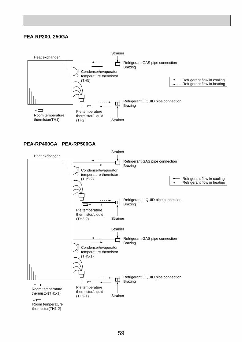
59
Heat exchanger
Refrigerant flow in coolingRefrigerant flow in heating
Strainer
Strainer
Room temperaturethermistor(TH1)
Refrigerant GAS pipe connectionBrazing
Refrigerant LIQUID pipe connectionBrazing
Condenser/evaporatortemperature thermistor(TH5)
Pie temperaturethermistor/Liquid(TH2)
Heat exchanger
Refrigerant flow in coolingRefrigerant flow in heating
Strainer
Strainer
Room temperaturethermistor(TH1-2)
Refrigerant GAS pipe connectionBrazing
Refrigerant LIQUID pipe connectionBrazing
Condenser/evaporatortemperature thermistor(TH5-2)
Pie temperaturethermistor/Liquid(TH2-2)
Strainer
Strainer
Room temperaturethermistor(TH1-1)
Refrigerant GAS pipe connectionBrazing
Refrigerant LIQUID pipe connectionBrazing
Condenser/evaporatortemperature thermistor(TH5-1)
Pie temperaturethermistor/Liquid(TH2-1)
PEA-RP400GA PEA-RP500GA
PEA-RP200, 250GA
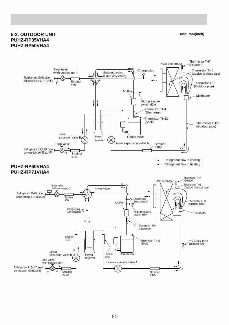
60
Distributor
Thermistor TH7(Outdoor)
Thermistor TH33(Outdoor pipe)
Heat exchanger
Refrigerant LIQUID pipeconnection 9.52(3/8)
Stop valve(with service port)
Strainer#100
Powerreceiver
Linearexpansion valve B
Linear expansion valve A
Strainer#100
Thermistor TH6(Outdoor 2-phase pipe)
Thermistor TH3(Outdoor pipe)
High pressureswitch 63H
Thermistor TH4(Discharge)
Thermistor TH32(Shell)
Compressor
Strainer#50
Strainer#100
Strainer#100
4-way valve
Muffler
Charge plug(Low pressure)
Charge plug(Higt pressure)
Stop valve(with service port)
Refrigerant GAS pipeconnection 15.88(5/8)
PUHZ-RP60VHA4PUHZ-RP71VHA4
5-2. OUTDOOR UNITPUHZ-RP35VHA4PUHZ-RP50VHA4
unit: mm(inch)
Refrigerant flow in coolingRefrigerant flow in heating
Thermistor TH7(Outdoor)Heat exchanger
Refrigerant GAS pipeconnection ø12.7 (1/2F)
Refrigerant LIQUID pipeconnection ø6.35 (1/4F)
Stop valve
Strainer#100
Powerreceiver
Linearexpansion valve B
Thermistor TH6(Outdoor 2-phase pipe)
Thermistor TH3(Outdoor pipe)
Charge plug
High pressureswitch 63H
Thermistor TH4(Discharge)
Thermistor TH32(Shell)
Compressor
Strainer#50
Solenoid valve(Four-way valve)
MufflerDistributor
Thermistor TH33(Outdoor pipe)
Linear expansion valve A Strainer#100
Stop valve(with service port)

61
unit: mm(inch)
Distributor
Thermistor TH7(Outdoor)
Thermistor TH33(Outdoor pipe)
Heat exchanger
Refrigerant LIQUID pipeconnection ø9.52 (3/8)
Stop valve(with service port)
Strainer#100
Powerreceiver
Linearexpansion valve B
Linear expansion valve A
Strainer#100
Thermistor TH6(Outdoor 2-phase pipe)
Thermistor TH3(Outdoor pipe)
High pressureswitch 63H
Thermistor TH4(Discharge)
Thermistor TH32(Shell)
Compressor
Strainer#50
Strainer#100
Strainer#100
Strainer#100
4-way valve
Muffler
Charge plug(Low pressure)
Charge plug(Higt pressure)
Ball valve
Refrigerant GAS pipeconnection ø15.88 (5/8)
Refrigerant flow in coolingRefrigerant flow in heating
PUHZ-RP100VKA PUHZ-RP125VKAPUHZ-RP100YKA PUHZ-RP125YKA
PUHZ-RP140VKA PUHZ-RP140YKA
Distributor
Thermistor TH7(Outdoor)
ThermistorTH33(Outdoor pipe)
Heat exchanger
Refrigerant LIQUIDpipe connection
9.52(3/8)
Stop valve(with service port)
Strainer#100
PowerreceiverLinear
Heat interchangecircuit
expansionvalve B
Linearexpansionvalve C
Linear expansion valve A
Strainer#100
Thermistor TH6(Outdoor 2-phase pipe)
Thermistor TH3(Outdoor pipe)
High pressureswitch 63H
Thermistor TH4(Discharge)
Thermistor TH32(Shell)
Compressor
Strainer #50
Strainer#100
Strainer#100
Strainer#100
4-way valve
Muffler
Charge plug(Low pressure)
Charge plug(Higt pressure)
Ball valve
Refrigerant GAS pipeconnection 15.88(5/8)

62
unit: mm(inch)PUHZ-RP200YKA
Distributor
Thermistor TH7(Outdoor)Heat exchanger
Refrigerant LIQUID pipeconnection 9.52(3/8)
Stop valve(with service port)
Strainer#100
Powerreceiver
Linearexpansion valve B
Linear expansion valve A
Strainer#100
Thermistor TH6(Outdoor 2-phase pipe)
Thermistor TH3(Outdoor pipe)
High pressureswitch 63H
Thermistor TH4(Discharge)
Thermistor TH32(Shell)
Compressor
Strainer#50
Strainer#100
Strainer#100
Strainer#100
4-way valve
Muffler
Charge plug(Low pressure)
Charge plug(Higt pressure)
Ball valve
Refrigerant GAS pipeconnection 25.4(1)
Refrigerant flow in coolingRefrigerant flow in heating
Distributor
Thermistor (TH7)Heat exchanger
Refrigerant LIQUID pipe12.7 (1/2)
Stop valve(with service port)
Strainer(#100)
Powerreceiver
Linearexpansion valve B
Linear expansion valve A
Strainer(#100)
Thermistor (TH6)
Thermistor (TH3)
High pressureswitch (63H1)
Thermistor (TH4)(Discharge)
Thermistor (TH32)(Shell)
Compressor
Strainer(#50)
Strainer(#100)
4-way valve
Muffler
Ball valve
Serviceport(check)
Serviceport(check)
High pressureswitch(63H2)
Refrigerant GAS pipe25.4 (1)
Strainer(#100)
Strainer(#100)
PUHZ-RP250YKA
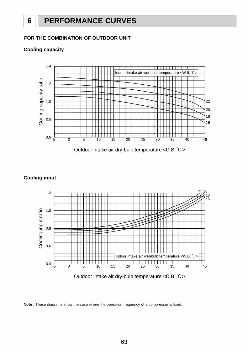
63
-5 0 5 10 15 20 25 30 35 40 46
1618
20
22
0.6
0.8
1.0
1.2
1.4
Coo
ling
capa
city
ratio
Outdoor intake air dry-bulb temperature <D.B. >
Coo
ling
inpu
t rat
io
Outdoor intake air dry-bulb temperature <D.B. >
-5 0 5 10 15 20 25 30 35 40 46
1618
2022
0.4
0.6
0.8
1.0
1.2
PERFORMANCE CURVES6
Note : These diagrams show the case where the operation frequency of a compressor is fixed.
FOR THE COMBINATION OF OUTDOOR UNIT
Cooling capacity
Cooling input
Indoor intake air wet-bulb temperature <W.B. :>
Indoor intake air wet-bulb temperature <W.B. :>
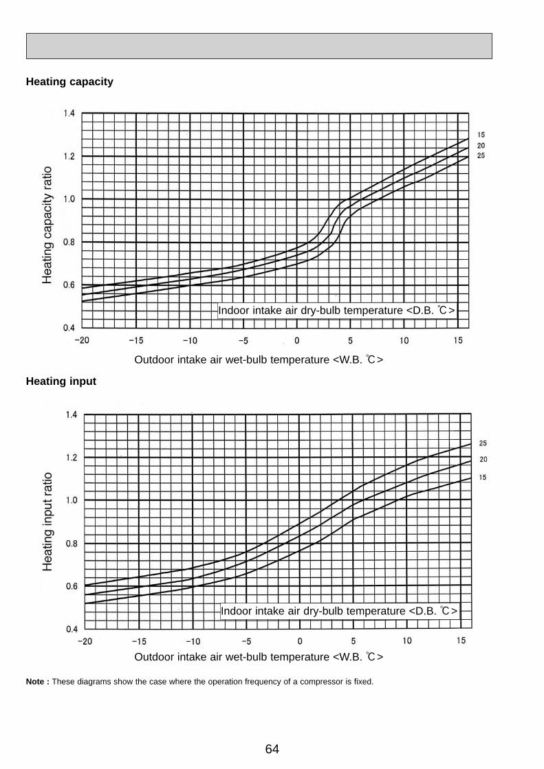
64
Note : These diagrams show the case where the operation frequency of a compressor is fixed.
Heating capacity
Heating input
Indoor intake air dry-bulb temperature <D.B. :>
Indoor intake air dry-bulb temperature <D.B. :>
Outdoor intake air wet-bulb temperature <W.B. :>
Outdoor intake air wet-bulb temperature <W.B. :>
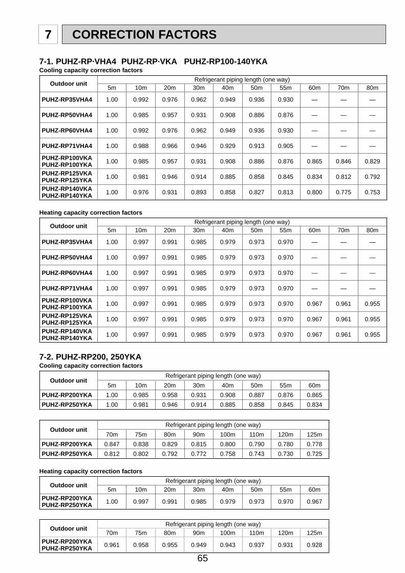
65
7-1. PUHZ-RP·VHA4 PUHZ-RP·VKA PUHZ-RP100-140YKACooling capacity correction factors
Outdoor unit Refrigerant piping length (one way)5m 10m 20m 30m 40m 50m 55m 60m 70m 80m
PUHZ-RP35VHA4 1.00 0.992 0.976 0.962 0.949 0.936 0.930 — — —
PUHZ-RP50VHA4 1.00 0.985 0.957 0.931 0.908 0.886 0.876 — — —
PUHZ-RP60VHA4 1.00 0.992 0.976 0.962 0.949 0.936 0.930 — — —
PUHZ-RP71VHA4 1.00 0.988 0.966 0.946 0.929 0.913 0.905 — — —
PUHZ-RP100VKAPUHZ-RP100YKA 1.00 0.985 0.957 0.931 0.908 0.886 0.876 0.865 0.846 0.829
PUHZ-RP125VKAPUHZ-RP125YKA 1.00 0.981 0.946 0.914 0.885 0.858 0.845 0.834 0.812 0.792
PUHZ-RP140VKAPUHZ-RP140YKA 1.00 0.976 0.931 0.893 0.858 0.827 0.813 0.800 0.775 0.753
Heating capacity correction factors
Outdoor unit Refrigerant piping length (one way)5m 10m 20m 30m 40m 50m 55m 60m 70m 80m
PUHZ-RP35VHA4 1.00 0.997 0.991 0.985 0.979 0.973 0.970 — — —
PUHZ-RP50VHA4 1.00 0.997 0.991 0.985 0.979 0.973 0.970 — — —
PUHZ-RP60VHA4 1.00 0.997 0.991 0.985 0.979 0.973 0.970 — — —
PUHZ-RP71VHA4 1.00 0.997 0.991 0.985 0.979 0.973 0.970 — — —
PUHZ-RP100VKAPUHZ-RP100YKA 1.00 0.997 0.991 0.985 0.979 0.973 0.970 0.967 0.961 0.955
PUHZ-RP125VKAPUHZ-RP125YKA 1.00 0.997 0.991 0.985 0.979 0.973 0.970 0.967 0.961 0.955
PUHZ-RP140VKAPUHZ-RP140YKA 1.00 0.997 0.991 0.985 0.979 0.973 0.970 0.967 0.961 0.955
7-2. PUHZ-RP200, 250YKACooling capacity correction factors
Outdoor unitRefrigerant piping length (one way)
5m 10m 20m 30m 40m 50m 55m 60mPUHZ-RP200YKA 1.00 0.985 0.958 0.931 0.908 0.887 0.876 0.865 PUHZ-RP250YKA 1.00 0.981 0.946 0.914 0.885 0.858 0.845 0.834
Outdoor unitRefrigerant piping length (one way)
70m 75m 80m 90m 100m 110m 120m 125mPUHZ-RP200YKA 0.847 0.838 0.829 0.815 0.800 0.790 0.780 0.778 PUHZ-RP250YKA 0.812 0.802 0.792 0.772 0.758 0.743 0.730 0.725
Heating capacity correction factors
Outdoor unitRefrigerant piping length (one way)
5m 10m 20m 30m 40m 50m 55m 60mPUHZ-RP200YKAPUHZ-RP250YKA 1.00 0.997 0.991 0.985 0.979 0.973 0.970 0.967
Outdoor unitRefrigerant piping length (one way)
70m 75m 80m 90m 100m 110m 120m 125mPUHZ-RP200YKAPUHZ-RP250YKA 0.961 0.958 0.955 0.949 0.943 0.937 0.931 0.928
7 CORRECTION FACTORS
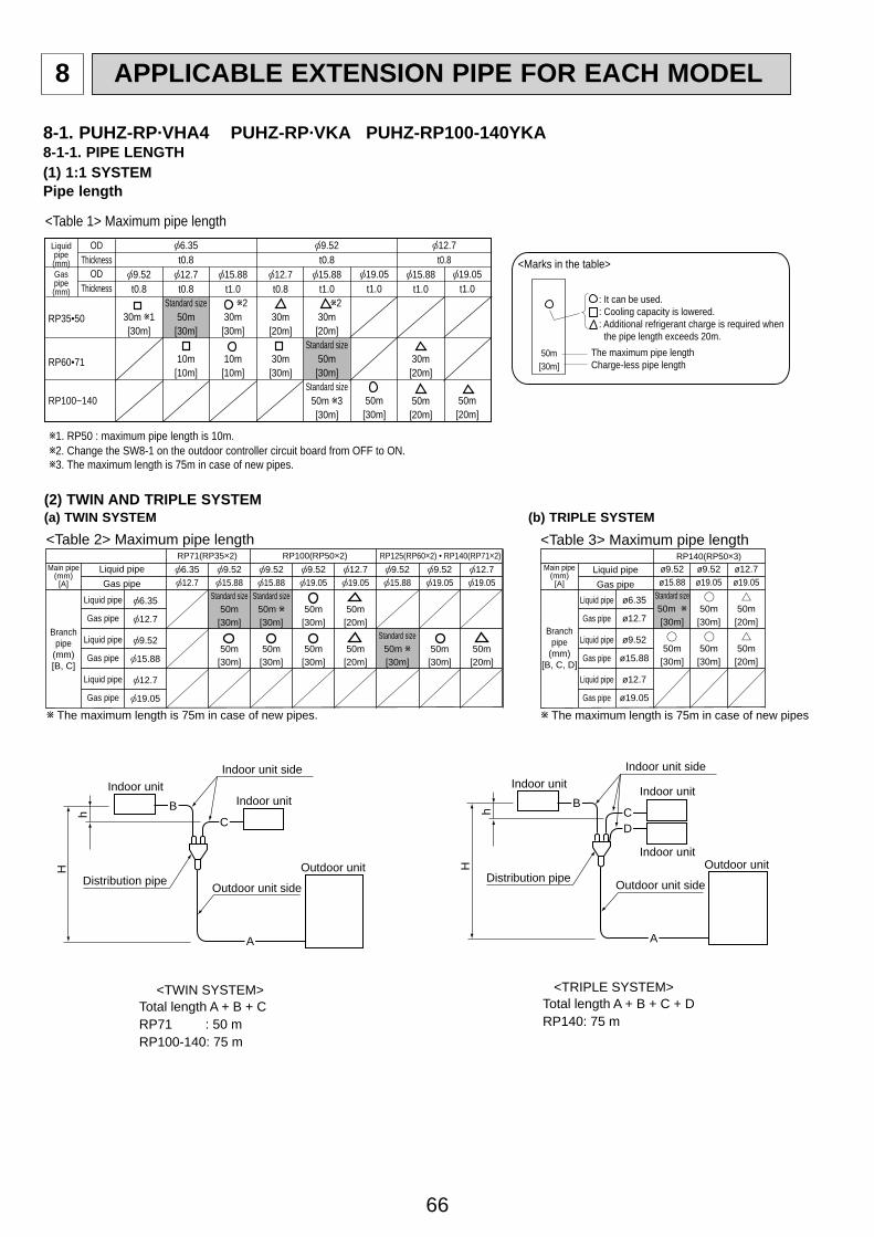
66
APPLICABLE EXTENSION PIPE FOR EACH MODEL8
8-1. PUHZ-RP·VHA4 PUHZ-RP·VKA PUHZ-RP100-140YKA8-1-1. PIPE LENGTH(1) 1:1 SYSTEMPipe length
(2) TWIN AND TRIPLE SYSTEM(a) TWIN SYSTEM (b) TRIPLE SYSTEM
RP35•50
RP60•71
RP100~140
Liquidpipe(mm)
<Table 1> Maximum pipe lengthOD
ThicknessOD
ThicknessGaspipe(mm)
12.7t0.8
30m[20m]
30m[30m]
15.88t1.0
230m[20m]
Standard size50m[30m]
Standard size50m 3[30m]
19.05t1.0
50m[30m]
15.88t1.0
30m[20m]
50m[20m]
19.05t1.0
50m[20m]
9.52t0.8
9.52t0.8
30m 1[30m]
12.7t0.8
Standard size50m[30m]
10m[10m]
15.88t1.0
230m[30m]
10m[10m]
6.35t0.8
12.7t0.8
1. RP50 : maximum pipe length is 10m.2. Change the SW8-1 on the outdoor controller circuit board from OFF to ON.3. The maximum length is 75m in case of new pipes.
50m[30m]
<Marks in the table>
The maximum pipe lengthCharge-less pipe length
: It can be used.: Cooling capacity is lowered. : Additional refrigerant charge is required when the pipe length exceeds 20m.
9.5215.88
Standard size50m[30m]
50m[30m]
9.5215.88
Standard size50m[30m]
9.5219.05
50m[30m]
50m[30m]
6.3512.7
9.5215.88
Standard size50m
[30m]
50m[30m]
9.5219.05
50m[30m]
12.719.05
50m[20m]
50m[20m]
12.719.05
50m[20m]
RP100(RP50 2)RP71(RP35 2) RP125(RP60 2) • RP140(RP71 2)
6.35
12.7
9.52
15.88
12.7
19.05
Liquid pipe
Gas pipe
Liquid pipe
Gas pipe
Liquid pipe
Gas pipe
Liquid pipeGas pipe
Branchpipe
(mm)[B, C]
Main pipe(mm)[A]
The maximum length is 75m in case of new pipes.
<Table 2> Maximum pipe length <Table 3> Maximum pipe length
Branchpipe
(mm)[B, C, D]
Main pipe(mm)[A]
ø9.52ø15.88
Standard size50m[30m]
50m[30m]
ø9.52ø19.05
50m[30m]
50m[30m]
ø12.7ø19.05
50m[20m]
50m[20m]
RP140(RP50 3)
ø6.35
ø12.7
ø9.52
ø15.88
ø12.7
ø19.05
Liquid pipe
Gas pipe
Liquid pipe
Gas pipe
Liquid pipe
Gas pipe
Liquid pipeGas pipe
The maximum length is 75m in case of new pipes.
A
CB
Indoor unit side
Outdoor unit side
Outdoor unit
Indoor unitIndoor unit
Distribution pipe
H
h
<TWIN SYSTEM>Total length A + B + CRP71 : 50 mRP100-140: 75 m
A
CB
D
Indoor unit side
Outdoor unit side
Outdoor unit
Indoor unit
Indoor unit
Indoor unit
Distribution pipe
H
h
<TRIPLE SYSTEM>Total length A + B + C + DRP140: 75 m
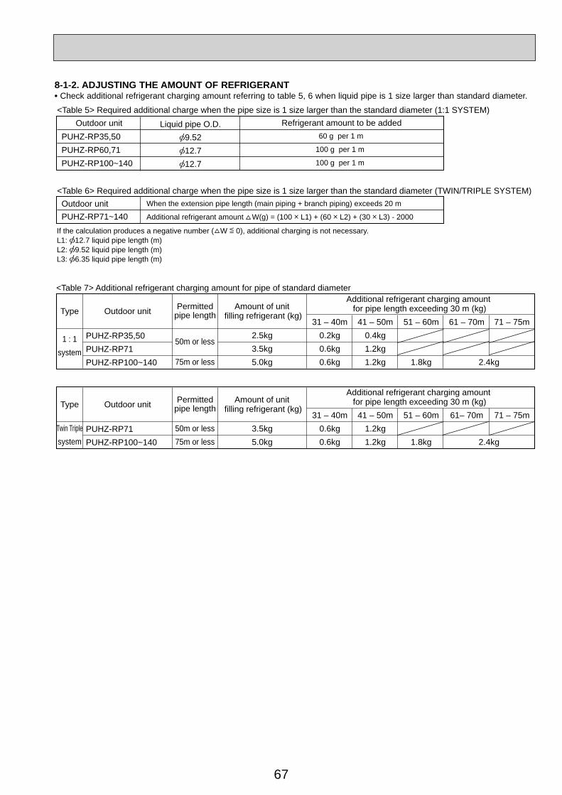
67
8-1-2. ADJUSTING THE AMOUNT OF REFRIGERANT• Check additional refrigerant charging amount referring to table 5, 6 when liquid pipe is 1 size larger than standard diameter.
9.5212.712.7
PUHZ-RP35,50PUHZ-RP60,71PUHZ-RP100~140
Liquid pipe O.D.60 g per 1 m
100 g per 1 m
100 g per 1 m
Refrigerant amount to be added
<Table 6> Required additional charge when the pipe size is 1 size larger than the standard diameter (TWIN/TRIPLE SYSTEM)
<Table 5> Required additional charge when the pipe size is 1 size larger than the standard diameter (1:1 SYSTEM)
Outdoor unitPUHZ-RP71~140
When the extension pipe length (main piping + branch piping) exceeds 20 m
Additional refrigerant amount W(g) = (100 L1) + (60 L2) + (30 L3) - 2000
If the calculation produces a negative number ( W 0), additional charging is not necessary. L1: 12.7 liquid pipe length (m)L2: 9.52 liquid pipe length (m)L3: 6.35 liquid pipe length (m)
Outdoor unit
2.5kg3.5kg5.0kg
31 – 40m0.2kg0.6kg0.6kg
41 – 50m0.4kg1.2kg1.2kg
51 – 60m
1.8kg
61 – 70m 71 – 75m
2.4kg
<Table 7> Additional refrigerant charging amount for pipe of standard diameter
Outdoor unitType
Type
Permittedpipe length
Additional refrigerant charging amount for pipe length exceeding 30 m (kg)Amount of unit
filling refrigerant (kg)
PUHZ-RP35,50PUHZ-RP71PUHZ-RP100~140
1 : 1system
50m or less
75m or less
3.5kg5.0kg
31 – 40m0.6kg0.6kg
41 – 50m1.2kg1.2kg
51 – 60m
1.8kg
61– 70m 71 – 75m
2.4kg
Outdoor unit Permittedpipe length
Additional refrigerant charging amount for pipe length exceeding 30 m (kg)Amount of unit
filling refrigerant (kg)
PUHZ-RP71PUHZ-RP100~140
Twin Triplesystem
50m or less75m or less
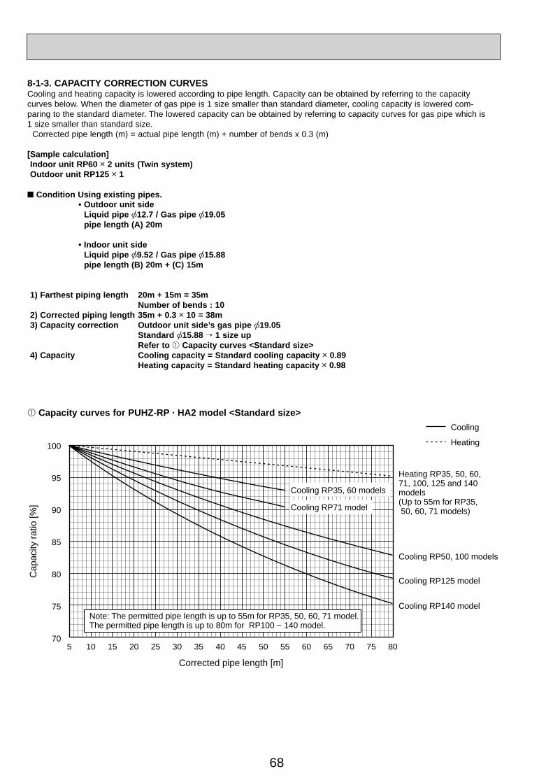
68
8-1-3. CAPACITY CORRECTION CURVESCooling and heating capacity is lowered according to pipe length. Capacity can be obtained by referring to the capacity curves below. When the diameter of gas pipe is 1 size smaller than standard diameter, cooling capacity is lowered com-paring to the standard diameter. The lowered capacity can be obtained by referring to capacity curves for gas pipe which is 1 size smaller than standard size. Corrected pipe length (m) = actual pipe length (m) + number of bends x 0.3 (m)
[Sample calculation] Indoor unit RP60 o 2 units (Twin system) Outdoor unit RP125 o 1
■ Condition Using existing pipes. • Outdoor unit side Liquid pipe [12.7 / Gas pipe [19.05 pipe length (A) 20m
• Indoor unit side Liquid pipe [9.52 / Gas pipe [15.88 pipe length (B) 20m + (C) 15m
1) Farthest piping length 20m + 15m = 35m Number of bends : 10 2) Corrected piping length 35m + 0.3 o 10 = 38m 3) Capacity correction Outdoor unit side’s gas pipe [19.05 Standard [15.88 → 1 size up Refer to 1 Capacity curves <Standard size> 4) Capacity Cooling capacity = Standard cooling capacity o 0.89 Heating capacity = Standard heating capacity o 0.98
1 Capacity curves for PUHZ-RP · HA2 model <Standard size>Cooling
Heating100
95
90
85
80
75
705 10 15 20 25 30 35 40 45 50 55 60 65 70 75 80
Note: The permitted pipe length is up to 55m for RP35, 50, 60, 71 model.The permitted pipe length is up to 80m for RP100 ~ 140 model.
Cooling RP71 model
Cooling RP35, 60 models
Cooling RP50, 100 models
Heating RP35, 50, 60, 71, 100, 125 and 140 models(Up to 55m for RP35, 50, 60, 71 models)
Cooling RP125 model
Cooling RP140 model
Cap
acity
ratio
[%]
Corrected pipe length [m]
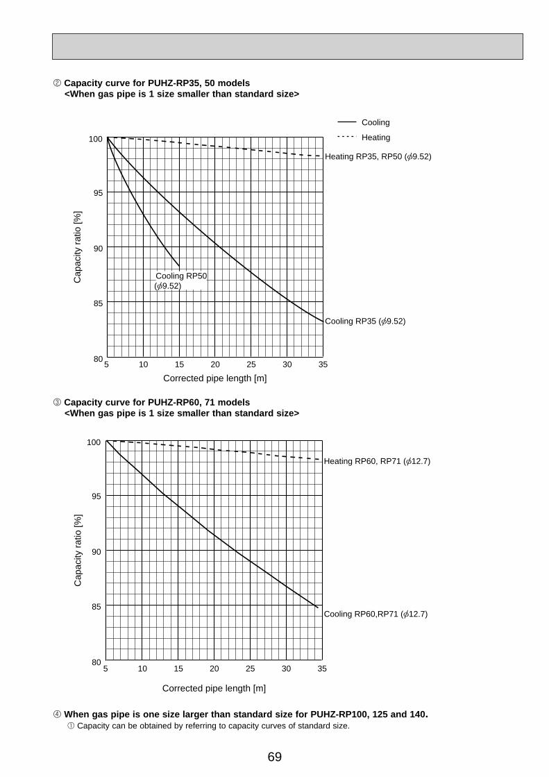
69
4 When gas pipe is one size larger than standard size for PUHZ-RP100, 125 and 140. 1 Capacity can be obtained by referring to capacity curves of standard size.
3 Capacity curve for PUHZ-RP60, 71 models <When gas pipe is 1 size smaller than standard size>
5 10 15 20 25 30 3580
Cap
acity
ratio
[%]
Corrected pipe length [m]
85
90
95
100
Heating RP60, RP71 ( 12.7)
Cooling RP60,RP71 ( 12.7)
2 Capacity curve for PUHZ-RP35, 50 models <When gas pipe is 1 size smaller than standard size>
5 10 15 20 25 30 3580
Cap
acity
ratio
[%]
Corrected pipe length [m]
85
90
95
100
Heating RP35, RP50 ( 9.52)
Cooling RP35 ( 9.52)
Cooling RP50( 9.52)
Cooling
Heating
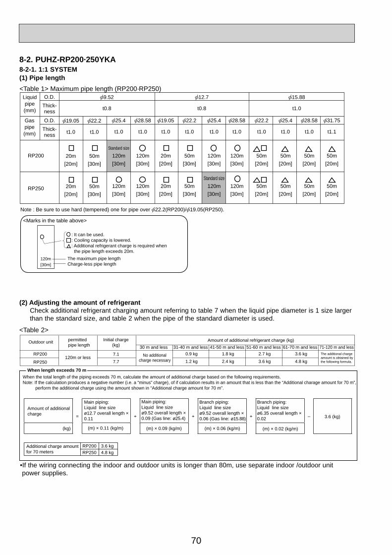
70
8-2. PUHZ-RP200·250YKA8-2-1. 1:1 SYSTEM(1) Pipe length
(2) Adjusting the amount of refrigerantCheck additional refrigerant charging amount referring to table 7 when the liquid pipe diameter is 1 size largerthan the standard size, and table 2 when the pipe of the standard diameter is used.
<Table 2>
<Table 1> Maximum pipe length (RP200·RP250)
Amount of additional refrigerant charge (kg)30 m and less 31-40 m and less 41-50 m and less 51-60 m and less 61-70 m and less 71-120 m and less
0.9 kg 1.8 kg 2.7 kg 3.6 kg
1.2 kg 2.4 kg 3.6 kg 4.8 kg
Outdoor unit permittedpipe length
RP200
RP250120m or less
Initial charge(kg)
7.17.7
No additionalcharge necessary
The additional charge amount is obtained by the following formula.
•If the wiring connecting the indoor and outdoor units is longer than 80m, use separate indoor /outdoor unit power supplies.
Note : Be sure to use hard (tempered) one for pipe over 22.2(RP200)/ 19.05(RP250).
120m[30m]
<Marks in the table above>
The maximum pipe lengthCharge-less pipe length
: It can be used.: Cooling capacity is lowered.: Additional refrigerant charge is required when the pipe length exceeds 20m.
Liquidpipe(mm)
Gaspipe(mm)
O.D.Thick-ness
O.D.Thick-ness
RP200
RP250
9.52
t0.8
12.7
t0.8
15.88
t1.0
19.05
t1.0
20m[20m]
20m[20m]
22.2
t1.0
50m[30m]
50m[30m]
25.4
t1.0
Standard size
120m[30m]
120m[30m]
28.58
t1.0
120m[30m]
120m[30m]
19.05
t1.0
20m[20m]
20m[20m]
22.2
t1.0
50m[30m]
50m[30m]
25.4
t1.0
120m[30m]
Standard size120m[30m]
22.2
t1.0
50m[20m]
50m[20m]
25.4
t1.0
50m[20m]
50m[20m]
28.58
t1.0
50m[20m]
50m[20m]
28.58
t1.0
120m[30m]
120m[30m]
31.75
t1.1
50m[20m]
50m[20m]
When length exceeds 70 mWhen the total length of the piping exceeds 70 m, calculate the amount of additional charge based on the following requirements.Note: If the calculation produces a negative number (i.e. a “minus” charge), of if calculation results in an amount that is less than the “Additional charage amount for 70 m”, perform the additional charge using the amount shown in “Additional charge amount for 70 m”.
Amount of additionalcharge =
Main piping:Liquid line sizeø12.7 overall length ×0.11 + + + – 3.6 (kg)
(kg) (m) × 0.11 (kg/m)
Additional charge amountfor 70 meters
RP200 3.6 kgRP250 4.8 kg
Main piping:Liquid line sizeø9.52 overall length ×0.09 (Gas line: ø25.4)
(m) × 0.09 (kg/m)
Branch piping:Liquid line sizeø9.52 overall length ×0.06 (Gas line: ø15.88)
(m) × 0.06 (kg/m) (m) × 0.02 (kg/m)
Branch piping:Liquid line sizeø6.35 overall length ×0.02
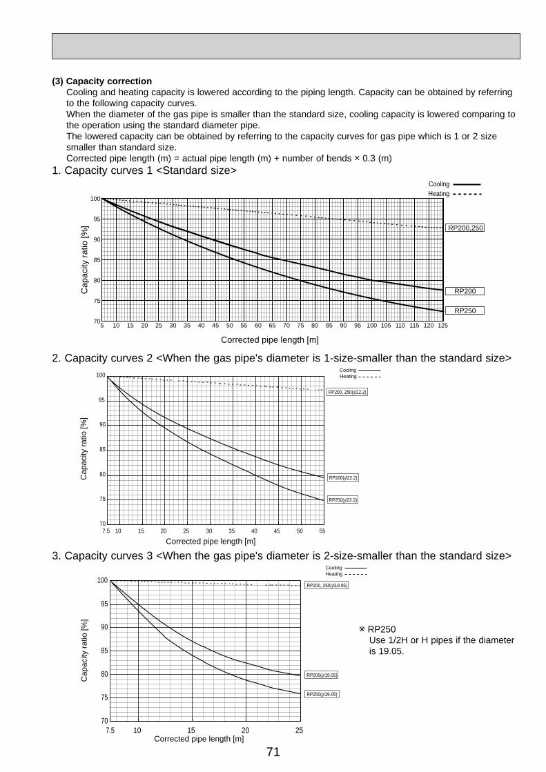
71
(3) Capacity correction Cooling and heating capacity is lowered according to the piping length. Capacity can be obtained by referring to the following capacity curves. When the diameter of the gas pipe is smaller than the standard size, cooling capacity is lowered comparing to the operation using the standard diameter pipe. The lowered capacity can be obtained by referring to the capacity curves for gas pipe which is 1 or 2 size smaller than standard size. Corrected pipe length (m) = actual pipe length (m) + number of bends o 0.3 (m)1. Capacity curves 1 <Standard size>
2. Capacity curves 2 <When the gas pipe's diameter is 1-size-smaller than the standard size>
3. Capacity curves 3 <When the gas pipe's diameter is 2-size-smaller than the standard size>
CoolingHeating
RP200
RP250
RP200,250
5 10 15 20 25 30 35 40 45 50 55 60 65 70 75 80 85 90 95 100 105 110 115 12512070
75
80
85
90
95
100
Corrected pipe length [m]
Cap
acity
ratio
[%]
HeatingCooling
70
75
80
85
90
95
100
7.5 10 15 20 25 30 35 40 45 50 55
Corrected pipe length [m]
Cap
acity
ratio
[%]
RP200( 22.2)
RP250( 22.2)
RP200, 250( 22.2)
RP200, 250( 19.05)
RP200( 19.05)
RP250( 19.05)
HeatingCooling
70
75
80
85
90
95
100
7.5 10 15 20 25Corrected pipe length [m]
Cap
acity
ratio
[%]
w RP250 Use 1/2H or H pipes if the diameter is 19.05.

72
Liquid pipeGas pipe
Liquid pipe
Gas pipe
Liquid pipe
Gas pipe
Liquid pipe
Gas pipe
19.05 22.2 25.4 28.58 19.05 22.2 25.4 28.58 22.2 25.4 28.58 31.75 19.05 22.2 25.4 28.58 19.05 22.2 25.4 28.58 22.2 25.4 28.58 31.759.52
RP250 twin (RP125 2)RP200 twin (RP100 2)12.7 15.88 9.52 12.7 15.88
15.88
9.52
9.52
19.05
12.7
19.05
20m[20m]
20m[20m]
20m[20m]
50m[30m]
50m[30m]
50m[30m]
Standardsize
120m[30m]
120m[30m]
20m[20m]
20m[20m]
20m[20m]
50m[30m]
50m[30m]
50m[30m]
120m[30m]
120m[30m]
120m[30m]
120m[30m]
120m[30m]
120m[30m]
120m[30m]
120m[30m]
120m[30m]
120m[30m]
50m[20m]
50m[20m]
50m[20m]
50m[20m]
50m[20m]
50m[20m]
50m[20m]
50m[20m]
50m[20m]
50m[20m]
50m[20m]
50m[20m]
20m[20m]
20m[20m]
20m[20m]
50m[30m]
50m[30m]
50m[30m]
120m[30m]
20m[20m]
20m[20m]
20m[20m]
50m[30m]
50m[30m]
50m[30m]
120m[30m]
120m[30m]
120m[30m]
120m[30m]
120m[30m]
120m[30m]
120m[30m]
120m[30m]
120m[30m]
120m[30m]
Standardsize
120m[30m]
50m[20m]
50m[20m]
50m[20m]
50m[20m]
50m[20m]
50m[20m]
50m[20m]
50m[20m]
50m[20m]
50m[20m]
50m[20m]
50m[20m]
Liquid pipeGas pipe
Liquid pipe
Gas pipe
Liquid pipe
Gas pipe
Liquid pipe
Gas pipe
19.05 22.2 25.4 28.58 19.05 22.2 25.4 28.58 22.2 25.4 28.58 31.75 19.05 22.2 25.4 28.58 19.05 22.2 25.4 28.58 22.2 25.4 28.58 31.759.52
RP250 triple (RP71 3)RP200 triple (RP60 3)12.7 15.88 9.52 12.7 15.88
15.88
9.52
9.52
19.05
12.7
19.05
Liquid pipe
Gas pipe
Liquid pipeGas pipe
Liquid pipe
Gas pipe
Liquid pipe
Gas pipe
Liquid pipe
Gas pipe
19.05 22.2 25.4 28.58 19.05 22.2 25.4 28.58 22.2 25.4 28.58 31.75 19.05 22.2 25.4 28.58 19.05 22.2 25.4 28.58 22.2 25.4 28.58 31.75
6.35
12.7
9.52RP250 quadruple (RP60 4)RP200 quadruple (RP50 4)
12.7 15.88 9.52 12.7 15.88
15.88
9.52
9.52
19.05
12.7
19.05
Standardsize
120m[30m]
20m[20m]
20m[20m]
20m[20m]
50m[30m]
50m[30m]
50m[30m]
120m[30m]
20m[20m]
20m[20m]
20m[20m]
50m[30m]
50m[30m]
50m[30m]
120m[30m]
120m[30m]
120m[30m]
120m[30m]
120m[30m]
120m[30m]
120m[30m]
120m[30m]
120m[30m]
120m[30m]
50m[20m]
50m[20m]
50m[20m]
50m[20m]
50m[20m]
50m[20m]
50m[20m]
50m[20m]
50m[20m]
50m[20m]
50m[20m]
50m[20m]
20m[20m]
20m[20m]
20m[20m]
50m[30m]
50m[30m]
50m[30m]
20m[20m]
20m[20m]
20m[20m]
50m[30m]
50m[30m]
50m[30m]
120m[30m]
120m[30m]
120m[30m]
120m[30m]
120m[30m]
120m[30m]
120m[30m]
120m[30m]
120m[30m]
120m[30m]
50m[20m]
50m[20m]
50m[20m]
50m[20m]
50m[20m]
50m[20m]
50m[20m]
50m[20m]
50m[20m]
• Be sure to use hard (tempered) one for pipe over 22.2(RP200)/ 19.05(RP250).
• Be sure to use hard (tempered) one for pipe over 22.2(RP200)/ 19.05(RP250).
• Be sure to use hard (tempered) one for pipe over 22.2(RP200)/ 19.05(RP250).
Maximum pipe length (Main pipe [A] + Branch pipe diameter [ B and C ])
Maximum pipe length (Main pipe [A] + Branch pipe [ B, C and D ])
Maximum pipe length (Main pipe [A] + Branch pipe [ B, C, D and E ])
Main pipe(mm)[A]
Main pipe(mm)[A]
Main pipe(mm)[A]
Branchpipe[mm][B, C]
Branchpipe[mm]
[B, C, D]
Branchpipe[mm]
[B, C, D, E] 50m[20m]
50m[20m]
50m[20m]
Standardsize
120m[30m]
120m[30m]
120m[30m]
<Marks in the table above>
The maximum pipe lengthCharge-less pipe length
: It can be used.: Cooling capacity is lowered. Refer to <Table6>.: Additional refrigerant charge is required when the pipe length exceeds 20m. Refer to <Table7>.
2. TWIN, TRIPLE AND QUADRUPLE SYSTEM(1) Twin
(2) Triple
(3) Quadruple
20m[20m]
20m[20m]
20m[20m]
50m[30m]
50m[30m]
50m[30m]
Standardsize
120m[30m]
120m[30m]
20m[20m]
20m[20m]
20m[20m]
50m[30m]
50m[30m]
50m[30m]
120m[30m]
120m[30m]
120m[30m]
120m[30m]
120m[30m]
120m[30m]
120m[30m]
120m[30m]
120m[30m]
120m[30m]
50m[20m]
50m[20m]
50m[20m]
50m[20m]
50m[20m]
50m[20m]
50m[20m]
50m[20m]
50m[20m]
50m[20m]
50m[20m]
50m[20m]
20m[20m]
20m[20m]
20m[20m]
50m[30m]
50m[30m]
50m[30m]
120m[30m]
20m[20m]
20m[20m]
20m[20m]
50m[30m]
50m[30m]
50m[30m]
120m[30m]
120m[30m]
120m[30m]
120m[30m]
120m[30m]
120m[30m]
120m[30m]
120m[30m]
120m[30m]
120m[30m]
Standardsize
120m[30m]
50m[20m]
50m[20m]
50m[20m]
50m[20m]
50m[20m]
50m[20m]
50m[20m]
50m[20m]
50m[20m]
50m[20m]
50m[20m]
50m[20m]
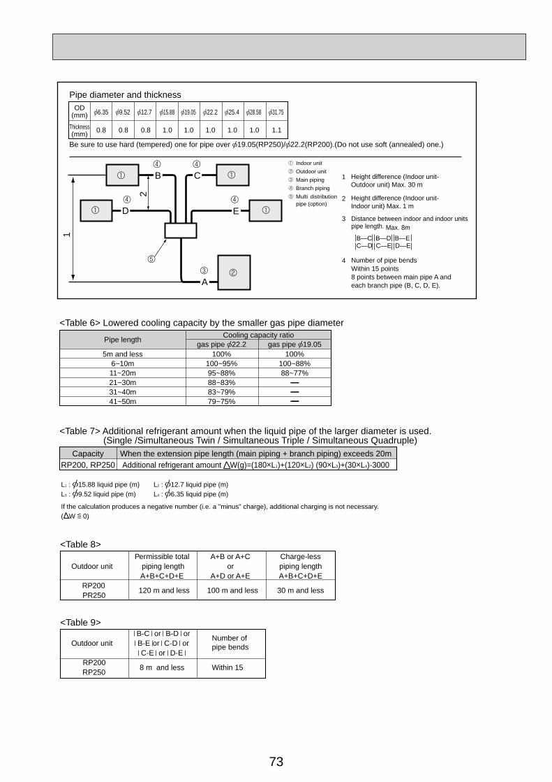
73
OD(mm)
Pipe diameter and thickness
6.35
0.8
Be sure to use hard (tempered) one for pipe over 19.05(RP250)/ 22.2(RP200).(Do not use soft (annealed) one.)
0.8 0.8 1.0 1.0 1.0 1.0 1.0
9.52 12.7 15.88 19.05 22.2 25.4 28.58
1.1
31.75
Thickness(mm)
1
4 Number of pipe bendsWithin 15 points 8 points between main pipe A and each branch pipe (B, C, D, E).
2
3 Distance between indoor and indoor unitspipe length. Max. 8m
B—C B—D B—EC—D C—E D—E
Indoor unitOutdoor unitMain pipingBranch pipingMulti distributionpipe (option)
E
A
1
B C
2
Height difference (Indoor unit-Outdoor unit) Max. 30 m
Height difference (Indoor unit-Indoor unit) Max. 1 mD
Permissible total A+B or A+C Charge-lessOutdoor unit piping length or piping length
A+B+C+D+E A+D or A+E A+B+C+D+ERP200 120 m and less 100 m and less 30 m and lessPR250
B-C or B-D orOutdoor unit B-E or C-D or
Number of pipe bends
C-E or D-E RP200 8 m and less Within 15RP250
<Table 6> Lowered cooling capacity by the smaller gas pipe diameter
5m and less6~10m11~20m21~30m31~40m41~50m
100%100~95%95~88%88~83%83~79%79~75%
100%100~88%88~77%
Pipe length gas pipe 22.2 gas pipe 19.05Cooling capacity ratio
<Table 7> Additional refrigerant amount when the liquid pipe of the larger diameter is used. (Single /Simultaneous Twin / Simultaneous Triple / Simultaneous Quadruple)
<Table 8>
<Table 9>
Additional refrigerant amount W(g)=(180 L1)+(120 L2) (90 L3)+(30 L4)-3000When the extension pipe length (main piping + branch piping) exceeds 20mCapacity
RP200, RP250
L1 : 15.88 liquid pipe (m) L2 : 12.7 liquid pipe (m)L3 : 9.52 liquid pipe (m) L4 : 6.35 liquid pipe (m)
If the calculation produces a negative number (i.e. a "minus" charge), additional charging is not necessary.( W 0)
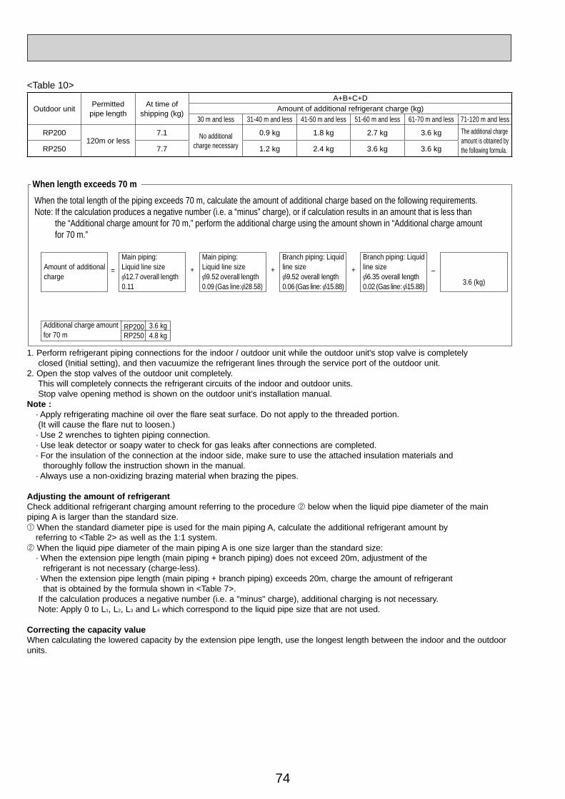
74
1. Perform refrigerant piping connections for the indoor / outdoor unit while the outdoor unit's stop valve is completely closed (Initial setting), and then vacuumize the refrigerant lines through the service port of the outdoor unit.2. Open the stop valves of the outdoor unit completely. This will completely connects the refrigerant circuits of the indoor and outdoor units. Stop valve opening method is shown on the outdoor unit’s installation manual.Note : · Apply refrigerating machine oil over the flare seat surface. Do not apply to the threaded portion. (It will cause the flare nut to loosen.) · Use 2 wrenches to tighten piping connection. · Use leak detector or soapy water to check for gas leaks after connections are completed. · For the insulation of the connection at the indoor side, make sure to use the attached insulation materials and thoroughly follow the instruction shown in the manual. · Always use a non-oxidizing brazing material when brazing the pipes.
Adjusting the amount of refrigerantCheck additional refrigerant charging amount referring to the procedure 2 below when the liquid pipe diameter of the main piping A is larger than the standard size.1 When the standard diameter pipe is used for the main piping A, calculate the additional refrigerant amount by referring to <Table 2> as well as the 1:1 system.2 When the liquid pipe diameter of the main piping A is one size larger than the standard size: · When the extension pipe length (main piping + branch piping) does not exceed 20m, adjustment of the refrigerant is not necessary (charge-less). · When the extension pipe length (main piping + branch piping) exceeds 20m, charge the amount of refrigerant that is obtained by the formula shown in <Table 7>. If the calculation produces a negative number (i.e. a "minus" charge), additional charging is not necessary. Note: Apply 0 to L1, L2, L3 and L4 which correspond to the liquid pipe size that are not used.
Correcting the capacity valueWhen calculating the lowered capacity by the extension pipe length, use the longest length between the indoor and the outdoor units.
Main piping:Liquid line size
9.52 overall length 0.09 (Gas line: 28.58)
Branch piping: Liquidline size
9.52 overall length0.06 (Gas line: 15.88)
Branch piping: Liquidline size
6.35 overall length 0.02 (Gas line: 15.88) 3.6 (kg)
Amount of additionalcharge
Main piping:Liquid line size
12.7 overall length0.11
–=
Additional charge amountfor 70 m
RP200 3.6 kgRP250 4.8 kg
When the total length of the piping exceeds 70 m, calculate the amount of additional charge based on the following requirements.Note: If the calculation produces a negative number (i.e. a “minus” charge), or if calculation results in an amount that is less than the “Additional charge amount for 70 m,” perform the additional charge using the amount shown in “Additional charge amount for 70 m.”
+ + +
When length exceeds 70 m
<Table 10>
Outdoor unit Permittedpipe length
At time of shipping (kg)
A+B+C+DAmount of additional refrigerant charge (kg)
30 m and less 31-40 m and less 41-50 m and less 51-60 m and less 61-70 m and less 71-120 m and less
RP200120m or less
7.1 No additionalcharge necessary
0.9 kg 1.8 kg 2.7 kg 3.6 kg The additional charge amount is obtained by the following formula. RP250 7.7 1.2 kg 2.4 kg 3.6 kg 3.6 kg
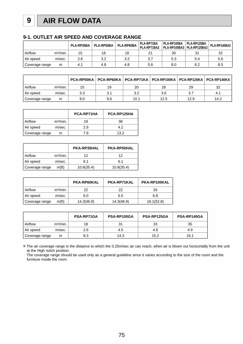
75
9 AIR FLOW DATA
9-1. OUTLET AIR SPEED AND COVERAGE RANGEPLA-RP35BA PLA-RP50BA PLA-RP60BA PLA-RP71BA
PLA-RP71BA2PLA-RP100BAPLA-RP100BA3
PLA-RP125BAPLA-RP125BA2 PLA-RP140BA2
Airfl ow m3/min. 15 18 18 21 30 31 32Air speed m/sec. 2.6 3.2 3.2 3.7 5.3 5.4 5.6Coverage range m 4.1 4.8 4.8 5.6 8.0 8.2 8.5
PCA-RP50KA PCA-RP60KA PCA-RP71KA PCA-RP100KA PCA-RP125KA PCA-RP140KA
Airfl ow m3/min. 15 19 20 28 29 32Air speed m/sec. 3.3 3.1 3.2 3.6 3.7 4.1Coverage range m 9.0 9.6 10.1 12.5 12.9 14.2
PCA-RP71HA PCA-RP125HA
Airfl ow m3/min. 19 38Air speed m/sec. 2.9 4.2Coverage range m 7.9 13.2
PKA-RP35HAL PKA-RP50HAL
Airfl ow m3/min. 12 12Air speed m/sec. 6.1 6.1Coverage range m(ft) 10.8(35.4) 10.8(35.4)
PKA-RP60KAL PKA-RP71KAL PKA-RP100KAL
Airfl ow m3/min. 22 22 26Air speed m/sec. 6.0 6.0 6.8Coverage range m(ft) 14.3(46.9) 14.3(46.9) 16.1(52.8)
PSA-RP71GA PSA-RP100GA PSA-RP125GA PSA-RP140GA
Airfl ow m3/min. 18 31 33 35Air speed m/sec. 2.6 4.5 4.8 4.9Coverage range m 8.3 14.3 15.2 16.1
w The air coverage range is the distance to which the 0.25m/sec air can reach, when air is blown out horizontally from the unit at the High notch position. The coverage range should be used only as a general guideline since it varies according to the size of the room and the furniture inside the room.
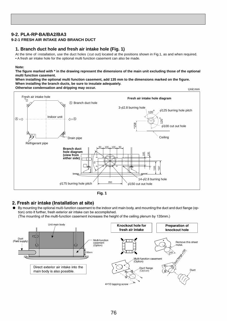
76
9-2. PLA-RP·BA/BA2/BA39-2-1 FRESH AIR INTAKE AND BRANCH DUCT
1. Branch duct hole and fresh air intake hole (Fig. 1)At the time of i nstallation, use the duct holes ( cut out) located at the positions shown in Fig.1, as and when required.• A fresh air intake hole for the optional multi function casement can also be made.
Note:The figure marked with * in the drawing represent the dimensions of the main unit excluding those of the optional multi function casement.When installing the optional multi function casement, add 135 mm to the dimensions marked on the figure.When installing the branch ducts, be sure to insulate adequately. Otherwise condensation and dripping may occur.
Branch duct hole
14- 2.8 burring hole
Indoor unit
150 cut out hole
Fresh air intake hole
175 burring hole pitch
Drain pipe
Fresh air intake hole diagram
Refrigerant pipe
3- 2.8 burring hole
Branch duct hole diagram (view from either side)
125 burring hole pitch
100 cut out hole
Ceiling
Unit:mm
*158
120
120
350
90
70
100 100 9010
0
130
*155
*167
Fig. 1
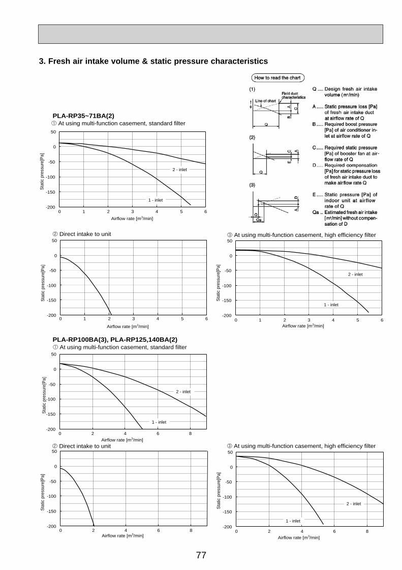
77
3. Fresh air intake volume & static pressure characteristics
-200
-150
-100
-50
0
50
0 1 2 3 4 5 6
2 - inlet
1 - inlet
At using multi-function casement, high efficiency filter
Stat
ic p
ress
ure[
Pa]
-200
-150
-100
-50
0
50
0 1 2 3 4 5 6
Direct intake to unit
Stat
ic p
ress
ure[
Pa]
-200
-150
-100
-50
0
50
0 2 4 6 8
Direct intake to unit
Stat
ic p
ress
ure[
Pa]
Stat
ic p
ress
ure[
Pa]
Stat
ic p
ress
ure[
Pa]
-200
-150
-100
-50
0
50
0 2 4 6 8
2 - inlet
1 - inlet
At using multi-function casement, standard filter
-200
-150
-100
-50
0
50
0 2 4 6 8
2 - inlet
1 - inlet
At using multi-function casement, high efficiency filter
-200
-150
-100
-50
0
50
0 1 2 3 4 5 6
2 - inlet
1 - inlet
Airflow rate [m3/min]
Airflow rate [m3/min]
Airflow rate [m3/min] Airflow rate [m3/min]
Airflow rate [m3/min] Airflow rate [m3/min]
At using multi-function casement, standard filterPLA-RP35~71BA(2)
PLA-RP100BA(3), PLA-RP125,140BA(2)
Stat
ic p
ress
ure[
Pa]
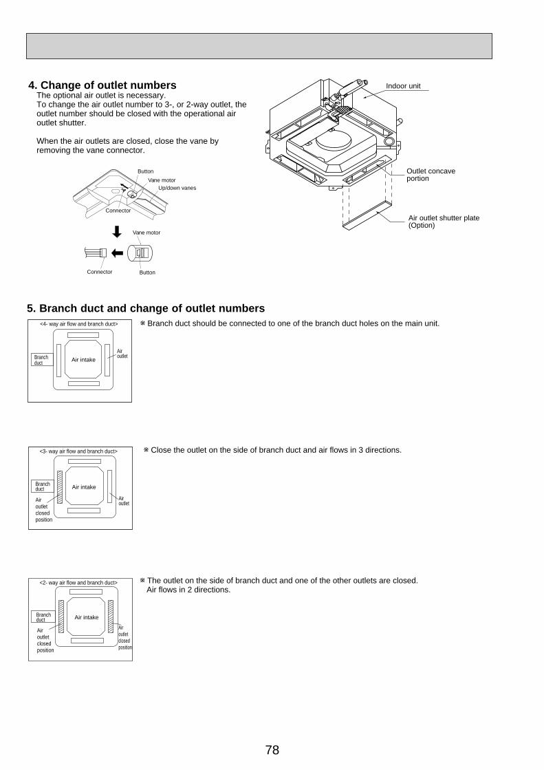
78
Indoor unit
Air outlet shutter plate (Option)
Outlet concaveportion
Button
Button
Vane motor
Vane motorUp/down vanes
Connector
Connector
4. Change of outlet numbersThe optional air outlet is necessary.To change the air outlet number to 3-, or 2-way outlet, the outlet number should be closed with the operational air outlet shutter.
When the air outlets are closed, close the vane by removing the vane connector.
5. Branch duct and change of outlet numbers<4- way air flow and branch duct> Branch duct should be connected to one of the branch duct holes on the main unit.
Branchduct Air intake
Airoutlet
<3- way air flow and branch duct> Close the outlet on the side of branch duct and air flows in 3 directions.
Branchduct Air intake
AiroutletAir
outletclosedposition
Airoutletclosedposition
<2- way air flow and branch duct> The outlet on the side of branch duct and one of the other outlets are closed. Air flows in 2 directions.
Air intakeBranchduct
Airoutletclosedposition
Airoutletclosedposition
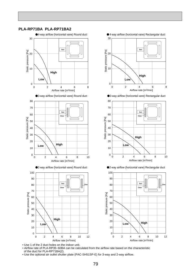
79
4-way airflow (horizontal vane) Round duct 4-way airflow (horizontal vane) Rectangular duct
3-way airflow (horizontal vane) Round duct 3-way airflow (horizontal vane) Rectangular duct
2-way airflow (horizontal vane) Round duct
• Use 1 of the 2 duct holes on the indoor unit.• Airflow rate of PLA-RP35~60BA can be calculated from the airflow rate based on the characteristic of the duct for PLA-RP71BA(2).• Use the optional air outlet shutter plate (PAC-SH51SP-E) for 3-way and 2-way airflow.
2-way airflow (horizontal vane) Rectangular duct
0
10
20
30
0 2
High
LowHigh
Low
HighLow
High
Low
HighLow
4 6 8Airflow rate [m3/min]
0 2 4 6 8Airflow rate [m3/min]
Airflow rate [m3/min]
Airflow rate [m3/min]
Sta
tic p
ress
ure
[Pa]
0
10
20
30
Sta
tic p
ress
ure
[Pa]
0
10
20
30
40
50
60
70
80
0 2 4 6 8 10Airflow rate [m3/min]
0 2 4 6 8 10
Sta
tic p
ress
ure
[Pa]
0
10
20
30
40
50
60
70
80S
tatic
pre
ssur
e [P
a]
0
10
20
30
40
50
60
70
80
90
100
0 2 4 6 8 10 12Airflow rate [m3/min]
0 2 4 6 8 10 12
Sta
tic p
ress
ure
[Pa]
0
10
20
30
40
50
60
70
80
90
100
Sta
tic p
ress
ure
[Pa]
HighLow
Duct Duct
Duct
Close
Duct
Close
Duct
Close
Close Duct
Close
Close
PLA-RP71BA PLA-RP71BA2
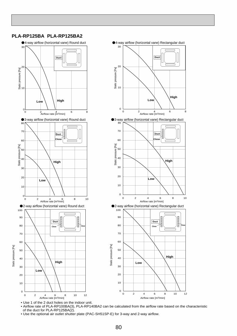
80
4-way airflow (horizontal vane) Round duct 4-way airflow (horizontal vane) Rectangular duct
0
10
20
30
0 2 4 6 8Airflow rate [m3/min] Airflow rate [m3/min]
Stat
ic pr
essu
re [P
a]
0
10
20
30
0 2 4 6 8St
atic
pres
sure
[Pa]
HighHigh
Low
DuctDuct
Low
0
10
20
30
40
50
60
70
80
0 2 4 6 8 10
0
10
20
30
40
50
60
70
0 2 4 6 8 10
3-way airflow (horizontal vane) Round duct 3-way airflow (horizontal vane) Rectangular duct
Airflow rate [m3/min] Airflow rate [m3/min]
Stat
ic pr
essu
re [P
a]
80
Stat
ic pr
essu
re [P
a]
High
Low
High
Low
DuctDuct
Close Close
• Use 1 of the 2 duct holes on the indoor unit.• Airflow rate of PLA-RP100BA(3), PLA-RP140BA2 can be calculated from the airflow rate based on the characteristic of the duct for PLA-RP125BA(2).• Use the optional air outlet shutter plate (PAC-SH51SP-E) for 3-way and 2-way airflow.
0
10
20
30
40
50
60
70
80
90
100
0 2 4 6 8 10 12
0
10
20
30
40
50
60
70
80
90
100
0 2 4 6 8 10 12
Close CloseClose Close
2-way airflow (horizontal vane) Round duct 2-way airflow (horizontal vane) Rectangular duct
Airflow rate [m3/min] Airflow rate [m3/min]
Stat
ic pr
essu
re [P
a]
Stat
ic pr
essu
re [P
a]
High
Low
High
Low
DuctDuct
PLA-RP125BA PLA-RP125BA2
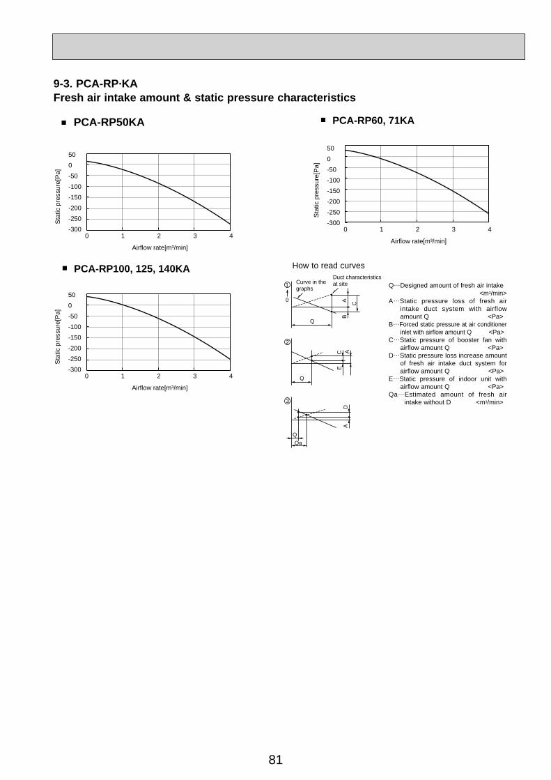
81
PCA-RP50KA PCA-RP60, 71KA■
500-50-100-150-200-250-300
Sta
tic p
ress
ure[
Pa]
Airflow rate[m³/min]
0 1 2 3 4
500-50-100-150-200-250-300
Sta
tic p
ress
ure[
Pa]
Airflow rate[m³/min]
0 1 2 3 4
500-50-100-150-200-250-300
Sta
tic p
ress
ure[
Pa]
Airflow rate[m³/min]
0 1 2 3 4
■
PCA-RP100, 125, 140KA■
9-3. PCA-RP·KAFresh air intake amount & static pressure characteristics
Q…Designed amount of fresh air intake <m3/min>
A…Static pressure loss of fresh air intake duct system with airflow amount Q <Pa>
B…Forced static pressure at air conditioner inlet with airflow amount Q <Pa>
C…Static pressure of booster fan with airflow amount Q <Pa>
D…Static pressure loss increase amount of fresh air intake duct system for airflow amount Q <Pa>
E…Static pressure of indoor unit with airflow amount Q <Pa>
Qa…Estimated amount of fresh air intake without D <m3/min>
How to read curves
Q
0
BA C
1 Curve in thegraphs
Duct characteristicsat site
Q
AE
C2
QQa
AD
3
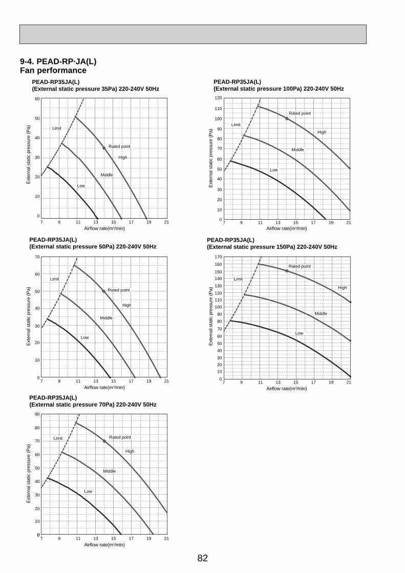
82
9-4. PEAD-RP·JA(L)Fan performance
PEAD-RP35JA(L)(External static pressure 35Pa) 220-240V 50Hz
PEAD-RP35JA(L)(External static pressure 100Pa) 220-240V 50Hz
PEAD-RP35JA(L)(External static pressure 50Pa) 220-240V 50Hz
PEAD-RP35JA(L)(External static pressure 150Pa) 220-240V 50Hz
PEAD-RP35JA(L)(External static pressure 70Pa) 220-240V 50Hz
60
Limit
Rated point
High
Middle
Low
7 9 11 13 15 17 19 21
50
40
30
20
10
0
Airflow rate(m3/min)
7 9 11 13 15 17 19 21Airflow rate(m3/min)
7 9 11 13 15 17 19 21Airflow rate(m3/min)
Exte
rnal
sta
tic p
ress
ure
(Pa)
60
70
50
40
30
20
10
0
7 9 11 13 15 17 19 21Airflow rate(m3/min)
0
Exte
rnal
sta
tic p
ress
ure
(Pa)
8090
100110120
130
140150
160
170
70
40
50
60
102030
0
Exte
rnal
sta
tic p
ress
ure
(Pa)
60
70
80
90
50
40
30
20
10
0
Exte
rnal
sta
tic p
ress
ure
(Pa)
7 9 11 13 15 17 19 21Airflow rate(m3/min)
60
70
80
90
100
110
120
50
40
30
20
10
0
Exte
rnal
sta
tic p
ress
ure
(Pa)
Limit
Rated point
High
Middle
Low
Limit Rated point
High
Middle
Low
Limit
Rated point
High
Middle
Low
Limit
Rated point
High
Middle
Low
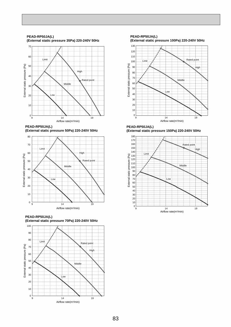
83
PEAD-RP50JA(L)(External static pressure 35Pa) 220-240V 50Hz
PEAD-RP50JA(L)(External static pressure 100Pa) 220-240V 50Hz
PEAD-RP50JA(L)(External static pressure 50Pa) 220-240V 50Hz
PEAD-RP50JA(L)(External static pressure 150Pa) 220-240V 50Hz
PEAD-RP50JA(L)(External static pressure 70Pa) 220-240V 50Hz
Airflow rate(m3/min)
Airflow rate(m3/min)Airflow rate(m3/min)
60
70
50
40
30
20
10
0
Exte
rnal
sta
tic p
ress
ure
(Pa)
Airflow rate(m3/min)
60
70
80
50
40
30
20
10
0
Exte
rnal
sta
tic p
ress
ure
(Pa)
8090
100110
120130140150160170180
70
4050
60
102030
0
Exte
rnal
sta
tic p
ress
ure
(Pa)
0
60
70
80
90
100
50
40
30
20
10
Exte
rnal
sta
tic p
ress
ure
(Pa)
9 14 19Airflow rate(m3/min)
60
70
80
90
100
110
120
130
50
40
30
20
10
0
Exte
rnal
sta
tic p
ress
ure
(Pa)
Rated point
High
Middle
Low
Limit
Rated point
High
Middle
Low
LimitRated point
High
Middle
Low
Limit
Rated point
High
Middle
Low
Limit Rated point
High
Middle
Low
Limit
9 14 19
9 14 19
9 14 19
9 14 19
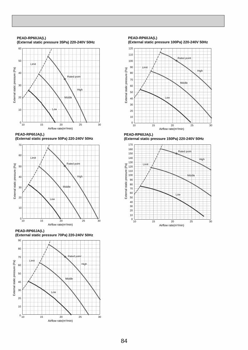
84
PEAD-RP60JA(L)(External static pressure 35Pa) 220-240V 50Hz
PEAD-RP60JA(L)(External static pressure 100Pa) 220-240V 50Hz
PEAD-RP60JA(L)(External static pressure 50Pa) 220-240V 50Hz
PEAD-RP60JA(L)(External static pressure 150Pa) 220-240V 50Hz
PEAD-RP60JA(L)(External static pressure 70Pa) 220-240V 50Hz
10 15 20 25 30Airflow rate(m3/min)
10 15 20 25 30Airflow rate(m3/min)
10 15 20 25 30Airflow rate(m3/min)
60
50
40
30
20
10
0
Exte
rnal
sta
tic p
ress
ure
(Pa)
10 15 20 25 30Airflow rate(m3/min)
60
70
50
40
30
20
10
0
Exte
rnal
sta
tic p
ress
ure
(Pa)
80
90
100110
120130140
150160
170
70
40
50
60
10
2030
0
Exte
rnal
sta
tic p
ress
ure
(Pa)
0
60
70
80
90
50
40
30
20
10
Exte
rnal
sta
tic p
ress
ure
(Pa)
10 15 20 25 30Airflow rate(m3/min)
60
70
80
90
100
110
120
50
40
30
20
10
0Ex
tern
al s
tatic
pre
ssur
e (P
a)
Rated point
High
Middle
Low
Limit
Rated point
High
Middle
Low
Limit
Limit
Rated point
High
Middle
Low
Limit
Rated point
High
Middle
Low
Limit
Rated point
High
Middle
Low
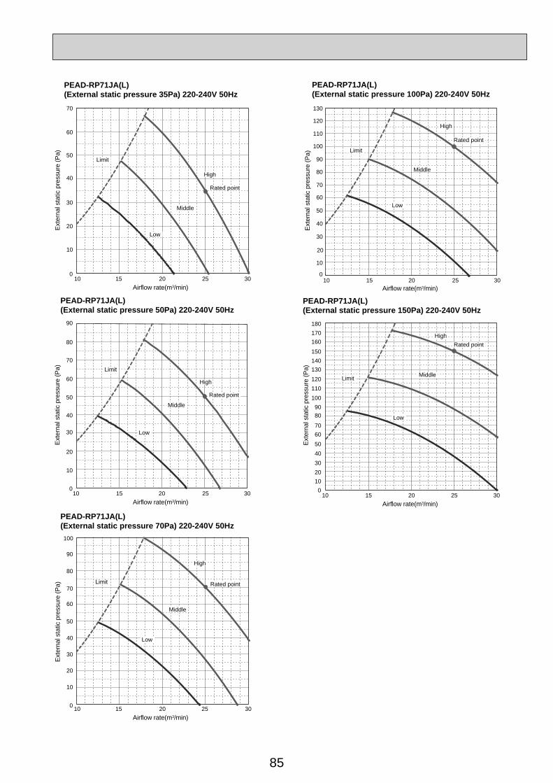
85
PEAD-RP71JA(L)(External static pressure 35Pa) 220-240V 50Hz
PEAD-RP71JA(L)(External static pressure 100Pa) 220-240V 50Hz
PEAD-RP71JA(L)(External static pressure 50Pa) 220-240V 50Hz
PEAD-RP71JA(L)(External static pressure 150Pa) 220-240V 50Hz
PEAD-RP71JA(L)(External static pressure 70Pa) 220-240V 50Hz
15 20 25 30Airflow rate(m3/min)
10 15 20 25 30Airflow rate(m3/min)
70
60
50
40
30
20
10
0
Exte
rnal
sta
tic p
ress
ure
(Pa)
10 15 20 25 30Airflow rate(m3/min)
60
70
80
90
50
40
30
20
10
0
Exte
rnal
sta
tic p
ress
ure
(Pa)
10
8090
100110120130140150
160170180
70
405060
102030
0
Exte
rnal
sta
tic p
ress
ure
(Pa)
10 15 20 25 30Airflow rate(m3/min)
0
60
70
80
90
100
50
40
30
20
10
Exte
rnal
sta
tic p
ress
ure
(Pa)
10 15 20 25 30Airflow rate(m3/min)
60
70
80
90
100
110
120
130
50
40
30
20
10
0
Exte
rnal
sta
tic p
ress
ure
(Pa)
Rated point
High
Middle
Low
Limit
Rated point
High
Middle
Low
Limit
Limit Rated point
High
Middle
Low
Rated point
High
Middle
Low
Limit
Limit
Rated pointHigh
Middle
Low
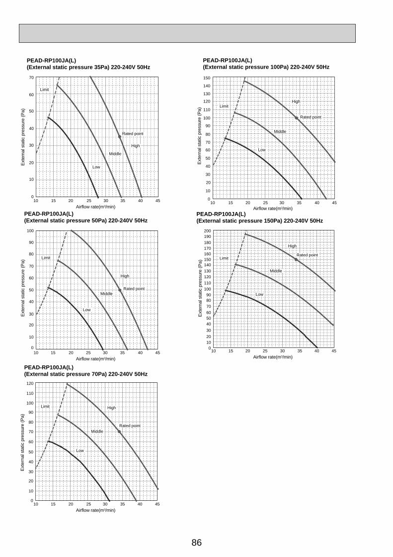
86
PEAD-RP100JA(L)(External static pressure 35Pa) 220-240V 50Hz
PEAD-RP100JA(L)(External static pressure 100Pa) 220-240V 50Hz
PEAD-RP100JA(L)(External static pressure 50Pa) 220-240V 50Hz
PEAD-RP100JA(L)(External static pressure 150Pa) 220-240V 50Hz
PEAD-RP100JA(L)(External static pressure 70Pa) 220-240V 50Hz
10 15 20 25 30 35 40 45Airflow rate(m3/min)
70
60
50
40
30
20
10
0
Exte
rnal
sta
tic p
ress
ure
(Pa)
10 15 20 25 30 35 40 45Airflow rate(m3/min)
60
70
80
90
100
50
40
30
20
10
0
Exte
rnal
sta
tic p
ress
ure
(Pa)
15 20 25 30 35 40 45Airflow rate(m3/min)
10
8090
100110120130140150160170180190200
70
405060
102030
0
Exte
rnal
sta
tic p
ress
ure
(Pa)
10 15 20 25 30 35 40 45Airflow rate(m3/min)
0
60
70
80
90
100
110
120
50
40
30
20
10
Exte
rnal
sta
tic p
ress
ure
(Pa)
10 15 20 25 30 35 40 45Airflow rate(m3/min)
60
70
80
90
100
110
120
130
140
150
50
40
30
20
10
0Ex
tern
al s
tatic
pre
ssur
e (P
a)
Limit
Rated point
High
Middle
Low
Rated point
High
Middle
Low
Limit
Rated point
High
Middle
Low
Limit
Rated point
High
Middle
Low
Limit
Rated point
High
Middle
Low
Limit

87
PEAD-RP125JA(L)(External static pressure 35Pa) 220-240V 50Hz
PEAD-RP125JA(L)(External static pressure 100Pa) 220-240V 50Hz
PEAD-RP125JA(L)(External static pressure 50Pa) 220-240V 50Hz
PEAD-RP125JA(L)(External static pressure 150Pa) 220-240V 50Hz
PEAD-RP125JA(L)(External static pressure 70Pa) 220-240V 50Hz
15 20 25 30 35 40 45Airflow rate(m3/min)
6070
8090
100110120
130140150160170
180
50403020100
Exte
rnal
sta
tic p
ress
ure
(Pa)
Rated point
High
Middle
Low
Limit
20 25 30 35 40 45Airflow rate(m3/min)
15
8090
100110120130140150160170180190200210220230
70
405060
102030
0
Exte
rnal
sta
tic p
ress
ure
(Pa)
Rated point
High
Middle
Low
Limit
15 20 25 30 35 40 45Airflow rate(m3/min)
70
60
50
40
30
20
10
0
Exte
rnal
sta
tic p
ress
ure
(Pa)
Rated point
High
Middle
Low
Limit
15 20 25 30 35 40 45Airflow rate(m3/min)
60
70
80
90
100
50
40
30
20
10
0
Exte
rnal
sta
tic p
ress
ure
(Pa)
Rated point
High
Middle
Low
Limit
15 20 25 30 35 40 45Airflow rate(m3/min)
0
60
70
80
90
100
110
120
130
140
150
5040
30
20
10
Exte
rnal
sta
tic p
ress
ure
(Pa)
Limit
Rated point
High
Middle
Low
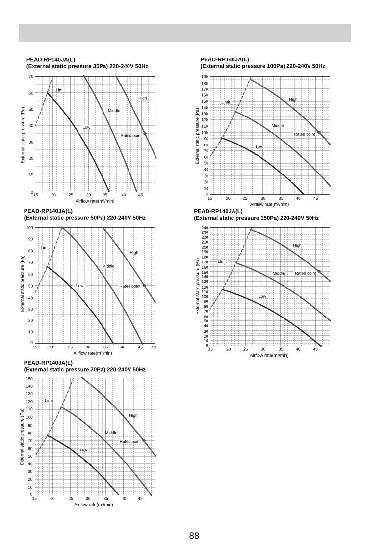
88
PEAD-RP140JA(L)(External static pressure 35Pa) 220-240V 50Hz
PEAD-RP140JA(L)(External static pressure 100Pa) 220-240V 50Hz
PEAD-RP140JA(L)(External static pressure 50Pa) 220-240V 50Hz
PEAD-RP140JA(L)(External static pressure 150Pa) 220-240V 50Hz
PEAD-RP140JA(L)(External static pressure 70Pa) 220-240V 50Hz
15 20 25 30 35 40 45Airflow rate(m3/min)
60708090
100110120130140150160170180
190
50403020100
Exte
rnal
sta
tic p
ress
ure
(Pa)
20 25 30 35 40 45Airflow rate(m3/min)
15
8090
100110120130140150160170180190200210220230240
70
405060
102030
0
Exte
rnal
sta
tic p
ress
ure
(Pa)
15 20 25 30 35 40 45Airflow rate(m3/min)
70
60
50
40
30
20
10
0
Exte
rnal
sta
tic p
ress
ure
(Pa)
15 20 25 30 35 40 5045Airflow rate(m3/min)
60
70
80
90
100
50
40
30
20
10
0
Exte
rnal
sta
tic p
ress
ure
(Pa)
15 20 25 30 35 40 45Airflow rate(m3/min)
0
60
70
80
90
100
110
120
130
140
150
50
40
30
20
10
Exte
rnal
sta
tic p
ress
ure
(Pa)
Rated point
High
Middle
Low
Limit
Rated point
High
Middle
Low
Limit
Rated point
High
Middle
Low
Limit
Rated point
High
Middle
Low
Limit
Rated point
High
Middle
Low
Limit

89
9-5. PEA-RP·GAFan Performance Curve
PEA-RP200GAFan Performance Curve 50Hz
PEA-RP250GAFan Performance Curve 50Hz
PEA-RP400GAFan Performance Curve 50Hz
PEA-RP500GAFan Performance Curve 50Hz
70.0 80.0 100.0 110.0 120.0 130.090.0
(Pa)
(Pa) (Pa)
Ext
erna
l sta
tic p
ress
ure
Airflow(CMM)
0
50
100
150
200
300
250
110.0100.0 120.0 130.0 140.0 150.0 160.0 170.0
(Pa)
Ext
erna
l sta
tic p
ress
ure
Airflow
(CMM)0
50
100
150
200
350
300
250
Hi
Lo
45.0 50.0 55.0 60.0 65.0 70.0
Hi
Lo
0
50
100
150
200
250
300
0
50
100
150
200
250
60.0 65.0 70.0 75.0 80.0 85.0 90.0
Ext
erna
l sta
tic p
ress
ure
Airflow Airflow(CMM) (CMM)
Ext
erna
l sta
tic p
ress
ure
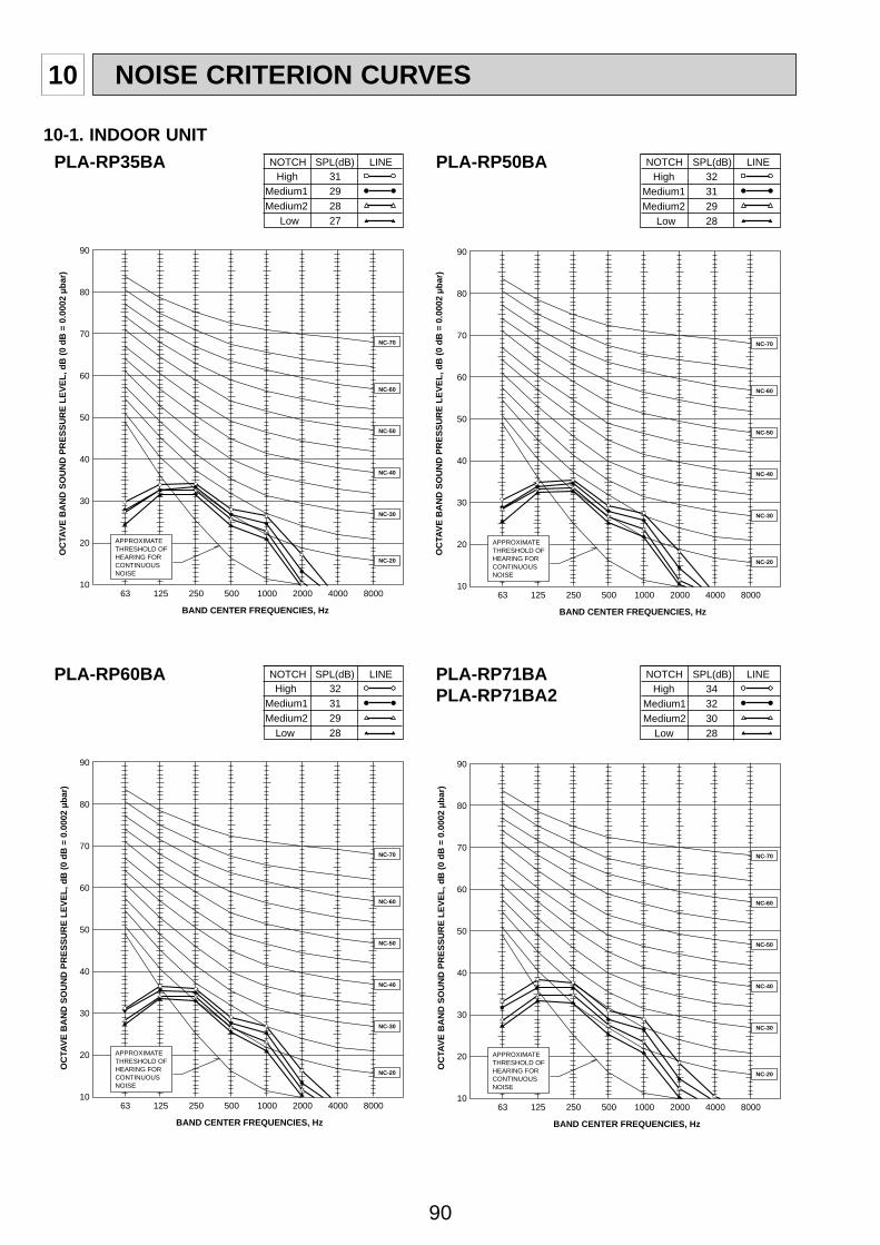
90
10 NOISE CRITERION CURVES
PLA-RP35BA PLA-RP50BANOTCH SPL(dB) LINEHigh 31
Medium1 29Medium2 28
Low 27
NOTCH SPL(dB) LINEHigh 32
Medium1 31Medium2 29
Low 28
90
80
70
60
50
40
30
20
1063 125 250 500 1000 2000 4000 8000
APPROXIMATETHRESHOLD OFHEARING FORCONTINUOUSNOISE
NC-60
NC-50
NC-40
NC-30
NC-20
NC-70
OC
TAVE
BA
ND
SO
UN
D P
RES
SUR
E LE
VEL,
dB
(0 d
B =
0.0
002 μb
ar)
OC
TAVE
BA
ND
SO
UN
D P
RES
SUR
E LE
VEL,
dB
(0 d
B =
0.0
002 μb
ar)
BAND CENTER FREQUENCIES, Hz
90
80
70
60
50
40
30
20
1063 125 250 500 1000 2000 4000 8000
APPROXIMATETHRESHOLD OFHEARING FORCONTINUOUSNOISE
NC-60
NC-50
NC-40
NC-30
NC-20
NC-70
BAND CENTER FREQUENCIES, Hz
PLA-RP60BA PLA-RP71BAPLA-RP71BA2
NOTCH SPL(dB) LINEHigh 32
Medium1 31Medium2 29
Low 28
NOTCH SPL(dB) LINEHigh 34
Medium1 32Medium2 30
Low 28
90
80
70
60
50
40
30
20
1063 125 250 500 1000 2000 4000 8000
APPROXIMATETHRESHOLD OFHEARING FORCONTINUOUSNOISE
NC-60
NC-50
NC-40
NC-30
NC-20
NC-70
BAND CENTER FREQUENCIES, Hz
90
80
70
60
50
40
30
20
1063 125 250 500 1000 2000 4000 8000
APPROXIMATETHRESHOLD OFHEARING FORCONTINUOUSNOISE
NC-60
NC-50
NC-40
NC-30
NC-20
NC-70
BAND CENTER FREQUENCIES, Hz
OC
TAVE
BA
ND
SO
UN
D P
RES
SUR
E LE
VEL,
dB
(0 d
B =
0.0
002 μb
ar)
OC
TAVE
BA
ND
SO
UN
D P
RES
SUR
E LE
VEL,
dB
(0 d
B =
0.0
002 μb
ar)
10-1. INDOOR UNIT

91
PLA-RP100BAPLA-RP100BA3
PLA-RP125BAPLA-RP125BA2
NOTCH SPL(dB) LINEHigh 40
Medium1 37Medium2 34
Low 32
NOTCH SPL(dB) LINEHigh 41
Medium1 39Medium2 36
Low 34
90
80
70
60
50
40
30
20
1063 125 250 500 1000 2000 4000 8000
APPROXIMATETHRESHOLD OFHEARING FORCONTINUOUSNOISE
NC-60
NC-50
NC-40
NC-30
NC-20
NC-70
OC
TAVE
BA
ND
SO
UN
D P
RES
SUR
E LE
VEL,
dB
(0 d
B =
0.0
002 μb
ar)
OC
TAVE
BA
ND
SO
UN
D P
RES
SUR
E LE
VEL,
dB
(0 d
B =
0.0
002 μb
ar)
BAND CENTER FREQUENCIES, Hz
PLA-RP140BA2 NOTCH SPL(dB) LINEHigh 44
Medium1 42Medium2 39
Low 36
90
80
70
60
50
40
30
20
1063 125 250 500 1000 2000 4000 8000
APPROXIMATETHRESHOLD OFHEARING FORCONTINUOUSNOISE
NC-60
NC-50
NC-40
NC-30
NC-20
NC-70
OC
TAVE
BA
ND
SO
UN
D P
RES
SUR
E LE
VEL,
dB
(0 d
B =
0.0
002 μb
ar)
BAND CENTER FREQUENCIES, Hz
90
80
70
60
50
40
30
20
1063 125 250 500 1000 2000 4000 8000
APPROXIMATETHRESHOLD OFHEARING FORCONTINUOUSNOISE
NC-60
NC-50
NC-40
NC-30
NC-20
NC-70
BAND CENTER FREQUENCIES, Hz
UNIT
1.5m
MICROPHONE
CEILING

92
Measurement location
2m
Ceiling concealed
2m
1.5m
Aux.duct
PEAD-RP·JA(L)
Noise level at anechoic room (Low-Middle-High) Unit: dB(A)
ModelExrernal static pressure
35Pa 50Pa 70Pa 100Pa 150PaPEAD-RP35JA(L) 23-26-29 23-27-30 24-28-31 26-29-33 29-33-37PEAD-RP50JA(L) 25-30-34 26-31-35 28-32-36 29-33-37 31-35-39PEAD-RP60JA(L) 25-28-32 25-29-33 26-30-34 27-31-35 29-34-38PEAD-RP71JA(L) 25-29-34 26-30-34 27-31-35 28-32-36 30-35-39PEAD-RP100JA(L) 28-33-38 29-34-38 30-35-39 31-36-40 34-40-43PEAD-RP125JA(L) 31-36-40 33-36-40 33-37-41 34-39-42 37-41-45PEAD-RP140JA(L) 33-37-43 34-38-43 34-39-44 36-40-45 38-42-46
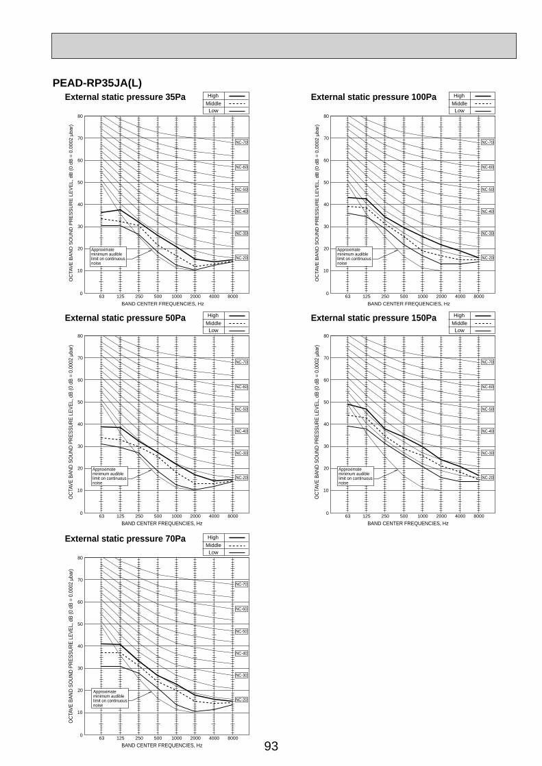
93
External static pressure 35Pa
External static pressure 50Pa
External static pressure 70Pa
HighMiddleLow
80
70
60
50
40
30
20
10
0 63 125 250 500 1000 2000 4000 8000
NC-60
NC-50
NC-40
NC-30
NC-20
NC-70
OC
TAV
E B
AN
D S
OU
ND
PR
ES
SU
RE
LE
VE
L, d
B (0
dB
= 0
.000
2 μb
ar)
BAND CENTER FREQUENCIES, Hz
HighMiddleLow
80
70
60
50
40
30
20
10
0 63 125 250 500 1000 2000 4000 8000
NC-60
NC-50
NC-40
NC-30
NC-20
NC-70
OCT
AVE
BAND
SO
UND
PRES
SURE
LEV
EL, d
B (0
dB
= 0.
0002
μba
r)
BAND CENTER FREQUENCIES, Hz
HighMiddleLow
80
70
60
50
40
30
20
10
0 63 125 250 500 1000 2000 4000 8000
Approximateminimum audiblelimit on continuousnoise
NC-60
NC-50
NC-40
NC-30
NC-20
NC-70
OCT
AVE
BAND
SO
UND
PRES
SURE
LEV
EL, d
B (0
dB
= 0.
0002
μba
r)
BAND CENTER FREQUENCIES, Hz
Approximateminimum audiblelimit on continuousnoise
Approximateminimum audiblelimit on continuousnoise
External static pressure 100Pa
External static pressure 150Pa
HighMiddleLow
80
70
60
50
40
30
20
10
0 63 125 250 500 1000 2000 4000 8000
NC-60
NC-50
NC-40
NC-30
NC-20
NC-70
OC
TAV
E B
AN
D S
OU
ND
PR
ES
SU
RE
LE
VE
L, d
B (0
dB
= 0
.000
2 μb
ar)
BAND CENTER FREQUENCIES, Hz
HighMiddleLow
80
70
60
50
40
30
20
10
0 63 125 250 500 1000 2000 4000 8000
NC-60
NC-50
NC-40
NC-30
NC-20
NC-70
OCT
AVE
BAND
SO
UND
PRES
SURE
LEV
EL, d
B (0
dB
= 0.
0002
μba
r)
BAND CENTER FREQUENCIES, Hz
Approximateminimum audiblelimit on continuousnoise
Approximateminimum audiblelimit on continuousnoise
PEAD-RP35JA(L)

94
PEAD-RP50JA(L)External static pressure 35Pa
External static pressure 50Pa
External static pressure 70Pa
HighMiddleLow
80
70
60
50
40
30
20
10
0 63 125 250 500 1000 2000 4000 8000
NC-60
NC-50
NC-40
NC-30
NC-20
NC-70
OC
TAV
E B
AN
D S
OU
ND
PR
ES
SU
RE
LE
VE
L, d
B (0
dB
= 0
.000
2 μb
ar)
BAND CENTER FREQUENCIES, Hz
HighMiddleLow
80
70
60
50
40
30
20
10
0 63 125 250 500 1000 2000 4000 8000
NC-60
NC-50
NC-40
NC-30
NC-20
NC-70
OCT
AVE
BAND
SO
UND
PRES
SURE
LEV
EL, d
B (0
dB
= 0.
0002
μba
r)
BAND CENTER FREQUENCIES, Hz
HighMiddleLow
80
70
60
50
40
30
20
10
0 63 125 250 500 1000 2000 4000 8000
Approximateminimum audiblelimit on continuousnoise
NC-60
NC-50
NC-40
NC-30
NC-20
NC-70
OCT
AVE
BAND
SO
UND
PRES
SURE
LEV
EL, d
B (0
dB
= 0.
0002
μba
r)
BAND CENTER FREQUENCIES, Hz
Approximateminimum audiblelimit on continuousnoise
Approximateminimum audiblelimit on continuousnoise
External static pressure 100Pa
External static pressure 150Pa
HighMiddleLow
80
70
60
50
40
30
20
10
0 63 125 250 500 1000 2000 4000 8000
NC-60
NC-50
NC-40
NC-30
NC-20
NC-70
OC
TAV
E B
AN
D S
OU
ND
PR
ES
SU
RE
LE
VE
L, d
B (0
dB
= 0
.000
2 μb
ar)
BAND CENTER FREQUENCIES, Hz
HighMiddleLow
80
70
60
50
40
30
20
10
0 63 125 250 500 1000 2000 4000 8000
NC-60
NC-50
NC-40
NC-30
NC-20
NC-70
OCT
AVE
BAND
SO
UND
PRES
SURE
LEV
EL, d
B (0
dB
= 0.
0002
μba
r)
BAND CENTER FREQUENCIES, Hz
Approximateminimum audiblelimit on continuousnoise
Approximateminimum audiblelimit on continuousnoise

95
External static pressure 35Pa
External static pressure 50Pa
External static pressure 70Pa
HighMiddleLow
80
70
60
50
40
30
20
10
0 63 125 250 500 1000 2000 4000 8000
NC-60
NC-50
NC-40
NC-30
NC-20
NC-70
OC
TAV
E B
AN
D S
OU
ND
PR
ES
SU
RE
LE
VE
L, d
B (0
dB
= 0
.000
2 μb
ar)
BAND CENTER FREQUENCIES, Hz
HighMiddleLow
80
70
60
50
40
30
20
10
0 63 125 250 500 1000 2000 4000 8000
NC-60
NC-50
NC-40
NC-30
NC-20
NC-70
OCT
AVE
BAND
SO
UND
PRES
SURE
LEV
EL, d
B (0
dB
= 0.
0002
μba
r)
BAND CENTER FREQUENCIES, Hz
HighMiddleLow
80
70
60
50
40
30
20
10
0 63 125 250 500 1000 2000 4000 8000
Approximateminimum audiblelimit on continuousnoise
NC-60
NC-50
NC-40
NC-30
NC-20
NC-70
OCT
AVE
BAND
SO
UND
PRES
SURE
LEV
EL, d
B (0
dB
= 0.
0002
μba
r)
BAND CENTER FREQUENCIES, Hz
Approximateminimum audiblelimit on continuousnoise
Approximateminimum audiblelimit on continuousnoise
External static pressure 100Pa
External static pressure 150Pa
HighMiddleLow
80
70
60
50
40
30
20
10
0 63 125 250 500 1000 2000 4000 8000
NC-60
NC-50
NC-40
NC-30
NC-20
NC-70
OC
TAV
E B
AN
D S
OU
ND
PR
ES
SU
RE
LE
VE
L, d
B (0
dB
= 0
.000
2 μb
ar)
BAND CENTER FREQUENCIES, Hz
HighMiddleLow
80
70
60
50
40
30
20
10
0 63 125 250 500 1000 2000 4000 8000
NC-60
NC-50
NC-40
NC-30
NC-20
NC-70
OCT
AVE
BAND
SO
UND
PRES
SURE
LEV
EL, d
B (0
dB
= 0.
0002
μba
r)
BAND CENTER FREQUENCIES, Hz
Approximateminimum audiblelimit on continuousnoise
Approximateminimum audiblelimit on continuousnoise
PEAD-RP60JA(L)

96
PEAD-RP71JA(L)External static pressure 35Pa
External static pressure 50Pa
External static pressure 70Pa
HighMiddleLow
80
70
60
50
40
30
20
10
0 63 125 250 500 1000 2000 4000 8000
NC-60
NC-50
NC-40
NC-30
NC-20
NC-70
OC
TAV
E B
AN
D S
OU
ND
PR
ES
SU
RE
LE
VE
L, d
B (0
dB
= 0
.000
2 μb
ar)
BAND CENTER FREQUENCIES, Hz
HighMiddleLow
80
70
60
50
40
30
20
10
0 63 125 250 500 1000 2000 4000 8000
NC-60
NC-50
NC-40
NC-30
NC-20
NC-70
OCT
AVE
BAND
SO
UND
PRES
SURE
LEV
EL, d
B (0
dB
= 0.
0002
μba
r)
BAND CENTER FREQUENCIES, Hz
HighMiddleLow
80
70
60
50
40
30
20
10
0 63 125 250 500 1000 2000 4000 8000
Approximateminimum audiblelimit on continuousnoise
NC-60
NC-50
NC-40
NC-30
NC-20
NC-70
OCT
AVE
BAND
SO
UND
PRES
SURE
LEV
EL, d
B (0
dB
= 0.
0002
μba
r)
BAND CENTER FREQUENCIES, Hz
Approximateminimum audiblelimit on continuousnoise
Approximateminimum audiblelimit on continuousnoise
External static pressure 100Pa
External static pressure 150Pa
HighMiddleLow
80
70
60
50
40
30
20
10
0 63 125 250 500 1000 2000 4000 8000
NC-60
NC-50
NC-40
NC-30
NC-20
NC-70
OC
TAV
E B
AN
D S
OU
ND
PR
ES
SU
RE
LE
VE
L, d
B (0
dB
= 0
.000
2 μb
ar)
BAND CENTER FREQUENCIES, Hz
HighMiddleLow
80
70
60
50
40
30
20
10
0 63 125 250 500 1000 2000 4000 8000
NC-60
NC-50
NC-40
NC-30
NC-20
NC-70
OCT
AVE
BAND
SO
UND
PRES
SURE
LEV
EL, d
B (0
dB
= 0.
0002
μba
r)
BAND CENTER FREQUENCIES, Hz
Approximateminimum audiblelimit on continuousnoise
Approximateminimum audiblelimit on continuousnoise
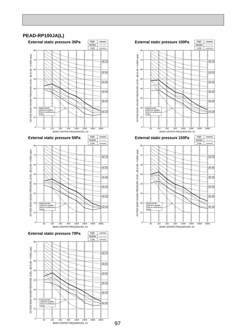
97
PEAD-RP100JA(L)External static pressure 35Pa
External static pressure 50Pa
External static pressure 70Pa
HighMiddleLow
80
70
60
50
40
30
20
10
0 63 125 250 500 1000 2000 4000 8000
NC-60
NC-50
NC-40
NC-30
NC-20
NC-70
OC
TAV
E B
AN
D S
OU
ND
PR
ES
SU
RE
LE
VE
L, d
B (0
dB
= 0
.000
2 μb
ar)
BAND CENTER FREQUENCIES, Hz
HighMiddleLow
80
70
60
50
40
30
20
10
0 63 125 250 500 1000 2000 4000 8000
NC-60
NC-50
NC-40
NC-30
NC-20
NC-70
OCT
AVE
BAND
SO
UND
PRES
SURE
LEV
EL, d
B (0
dB
= 0.
0002
μba
r)
BAND CENTER FREQUENCIES, Hz
HighMiddleLow
80
70
60
50
40
30
20
10
0 63 125 250 500 1000 2000 4000 8000
Approximateminimum audiblelimit on continuousnoise
NC-60
NC-50
NC-40
NC-30
NC-20
NC-70
OCT
AVE
BAND
SO
UND
PRES
SURE
LEV
EL, d
B (0
dB
= 0.
0002
μba
r)
BAND CENTER FREQUENCIES, Hz
Approximateminimum audiblelimit on continuousnoise
Approximateminimum audiblelimit on continuousnoise
External static pressure 100Pa
External static pressure 150Pa
HighMiddleLow
80
70
60
50
40
30
20
10
0 63 125 250 500 1000 2000 4000 8000
NC-60
NC-50
NC-40
NC-30
NC-20
NC-70
OC
TAV
E B
AN
D S
OU
ND
PR
ES
SU
RE
LE
VE
L, d
B (0
dB
= 0
.000
2 μb
ar)
BAND CENTER FREQUENCIES, Hz
HighMiddleLow
80
70
60
50
40
30
20
10
0 63 125 250 500 1000 2000 4000 8000
NC-60
NC-50
NC-40
NC-30
NC-20
NC-70
OCT
AVE
BAND
SO
UND
PRES
SURE
LEV
EL, d
B (0
dB
= 0.
0002
μba
r)
BAND CENTER FREQUENCIES, Hz
Approximateminimum audiblelimit on continuousnoise
Approximateminimum audiblelimit on continuousnoise
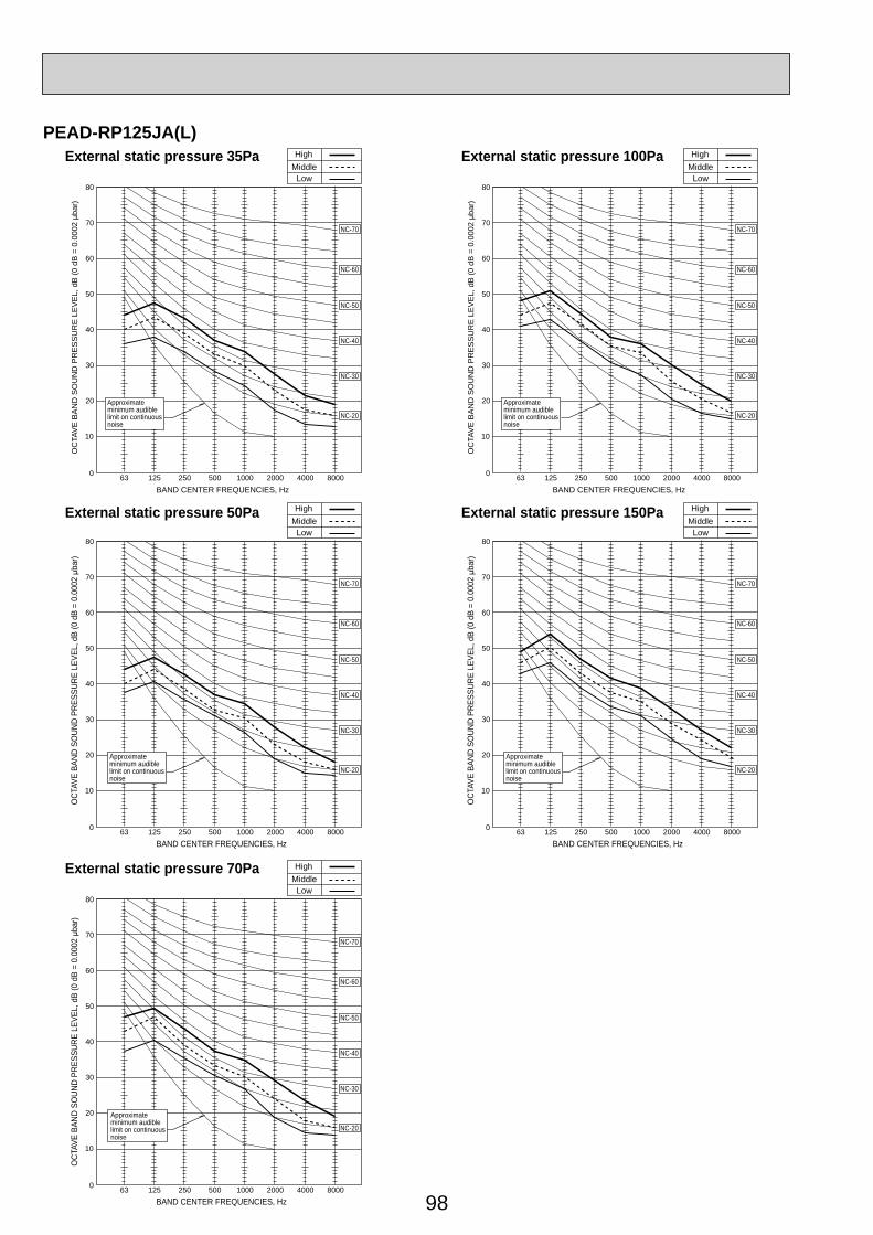
98
PEAD-RP125JA(L)External static pressure 35Pa
External static pressure 50Pa
External static pressure 70Pa
HighMiddleLow
80
70
60
50
40
30
20
10
0 63 125 250 500 1000 2000 4000 8000
NC-60
NC-50
NC-40
NC-30
NC-20
NC-70
OC
TAV
E B
AN
D S
OU
ND
PR
ES
SU
RE
LE
VE
L, d
B (0
dB
= 0
.000
2 μb
ar)
BAND CENTER FREQUENCIES, Hz
HighMiddleLow
80
70
60
50
40
30
20
10
0 63 125 250 500 1000 2000 4000 8000
NC-60
NC-50
NC-40
NC-30
NC-20
NC-70
OCT
AVE
BAND
SO
UND
PRES
SURE
LEV
EL, d
B (0
dB
= 0.
0002
μba
r)
BAND CENTER FREQUENCIES, Hz
HighMiddleLow
80
70
60
50
40
30
20
10
0 63 125 250 500 1000 2000 4000 8000
Approximateminimum audiblelimit on continuousnoise
NC-60
NC-50
NC-40
NC-30
NC-20
NC-70
OCT
AVE
BAND
SO
UND
PRES
SURE
LEV
EL, d
B (0
dB
= 0.
0002
μba
r)
BAND CENTER FREQUENCIES, Hz
Approximateminimum audiblelimit on continuousnoise
Approximateminimum audiblelimit on continuousnoise
External static pressure 100Pa
External static pressure 150Pa
HighMiddleLow
80
70
60
50
40
30
20
10
0 63 125 250 500 1000 2000 4000 8000
NC-60
NC-50
NC-40
NC-30
NC-20
NC-70
OC
TAV
E B
AN
D S
OU
ND
PR
ES
SU
RE
LE
VE
L, d
B (0
dB
= 0
.000
2 μb
ar)
BAND CENTER FREQUENCIES, Hz
HighMiddleLow
80
70
60
50
40
30
20
10
0 63 125 250 500 1000 2000 4000 8000
NC-60
NC-50
NC-40
NC-30
NC-20
NC-70
OCT
AVE
BAND
SO
UND
PRES
SURE
LEV
EL, d
B (0
dB
= 0.
0002
μba
r)
BAND CENTER FREQUENCIES, Hz
Approximateminimum audiblelimit on continuousnoise
Approximateminimum audiblelimit on continuousnoise

99
PEAD-RP140JA(L)External static pressure 35Pa
External static pressure 50Pa
External static pressure 70Pa
HighMiddleLow
80
70
60
50
40
30
20
10
0 63 125 250 500 1000 2000 4000 8000
NC-60
NC-50
NC-40
NC-30
NC-20
NC-70
OC
TAV
E B
AN
D S
OU
ND
PR
ES
SU
RE
LE
VE
L, d
B (0
dB
= 0
.000
2 μb
ar)
BAND CENTER FREQUENCIES, Hz
HighMiddleLow
80
70
60
50
40
30
20
10
0 63 125 250 500 1000 2000 4000 8000
NC-60
NC-50
NC-40
NC-30
NC-20
NC-70
OCT
AVE
BAND
SO
UND
PRES
SURE
LEV
EL, d
B (0
dB
= 0.
0002
μba
r)
BAND CENTER FREQUENCIES, Hz
HighMiddleLow
80
70
60
50
40
30
20
10
0 63 125 250 500 1000 2000 4000 8000
Approximateminimum audiblelimit on continuousnoise
NC-60
NC-50
NC-40
NC-30
NC-20
NC-70
OCT
AVE
BAND
SO
UND
PRES
SURE
LEV
EL, d
B (0
dB
= 0.
0002
μba
r)
BAND CENTER FREQUENCIES, Hz
Approximateminimum audiblelimit on continuousnoise
Approximateminimum audiblelimit on continuousnoise
External static pressure 100Pa
External static pressure 150Pa
HighMiddleLow
80
70
60
50
40
30
20
10
0 63 125 250 500 1000 2000 4000 8000
NC-60
NC-50
NC-40
NC-30
NC-20
NC-70
OC
TAV
E B
AN
D S
OU
ND
PR
ES
SU
RE
LE
VE
L, d
B (0
dB
= 0
.000
2 μb
ar)
BAND CENTER FREQUENCIES, Hz
HighMiddleLow
80
70
60
50
40
30
20
10
0 63 125 250 500 1000 2000 4000 8000
NC-60
NC-50
NC-40
NC-30
NC-20
NC-70
OCT
AVE
BAND
SO
UND
PRES
SURE
LEV
EL, d
B (0
dB
= 0.
0002
μba
r)
BAND CENTER FREQUENCIES, Hz
Approximateminimum audiblelimit on continuousnoise
Approximateminimum audiblelimit on continuousnoise
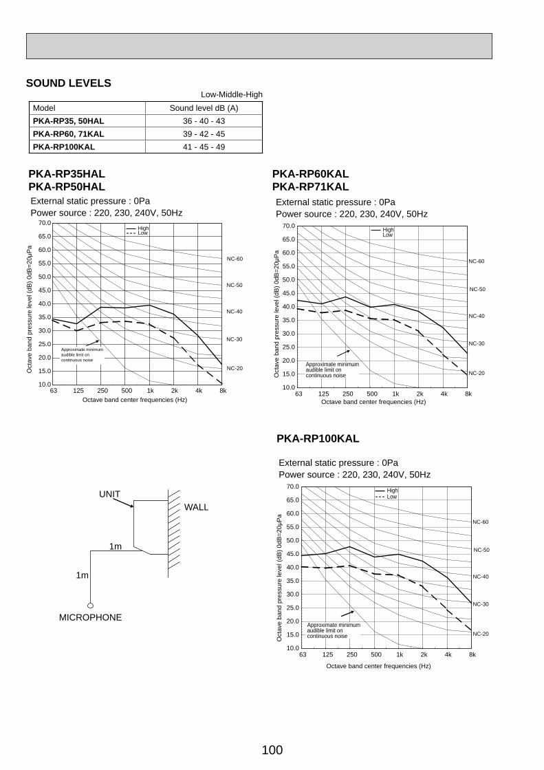
100
PKA-RP60KALPKA-RP71KALExternal static pressure : 0PaPower source : 220, 230, 240V, 50Hz
10.0
15.0
20.0
25.0
30.0
35.0
40.0
45.0
50.0
55.0
60.0
65.0
70.0
63 125 250 500 1k 2k 4k 8k
NC-60
NC-50
Oct
ave
band
pre
ssur
e le
vel (
dB) 0
dB=2
0μP
a
Approximate minimumaudible limit oncontinuous noise
NC-40
Octave band center frequencies (Hz)
NC-20
NC-30
HighLow
PKA-RP100KAL
External static pressure : 0PaPower source : 220, 230, 240V, 50Hz
10.0
15.0
20.0
25.0
30.0
35.0
40.0
45.0
50.0
55.0
60.0
65.0
70.0
63 125 250 500 1k 2k 4k 8k
NC-60
NC-50
Oct
ave
band
pre
ssur
e le
vel (
dB) 0
dB=2
0μP
a
NC-40
Octave band center frequencies (Hz)
NC-20
NC-30
HighLow
Approximate minimumaudible limit oncontinuous noise
UNITWALL
1m
1m
MICROPHONE
PKA-RP35HALPKA-RP50HAL
10.0
15.0
20.0
25.0
30.0
35.0
40.0
45.0
50.0
55.0
60.0
65.0
70.0
63 125 250 500 1k 2k 4k 8k
NC-60
NC-50
Approximate minimumaudible limit oncontinuous noise
NC-40
NC-20
NC-30
External static pressure : 0PaPower source : 220, 230, 240V, 50Hz
Oct
ave
band
pres
sure
leve
l(dB
)0dB
=20μ
Pa
Octave band center frequencies (Hz)
HighLow
SOUND LEVELSLow-Middle-High
Model Sound level dB (A)PKA-RP35, 50HAL 36 - 40 - 43PKA-RP60, 71KAL 39 - 42 - 45PKA-RP100KAL 41 - 45 - 49
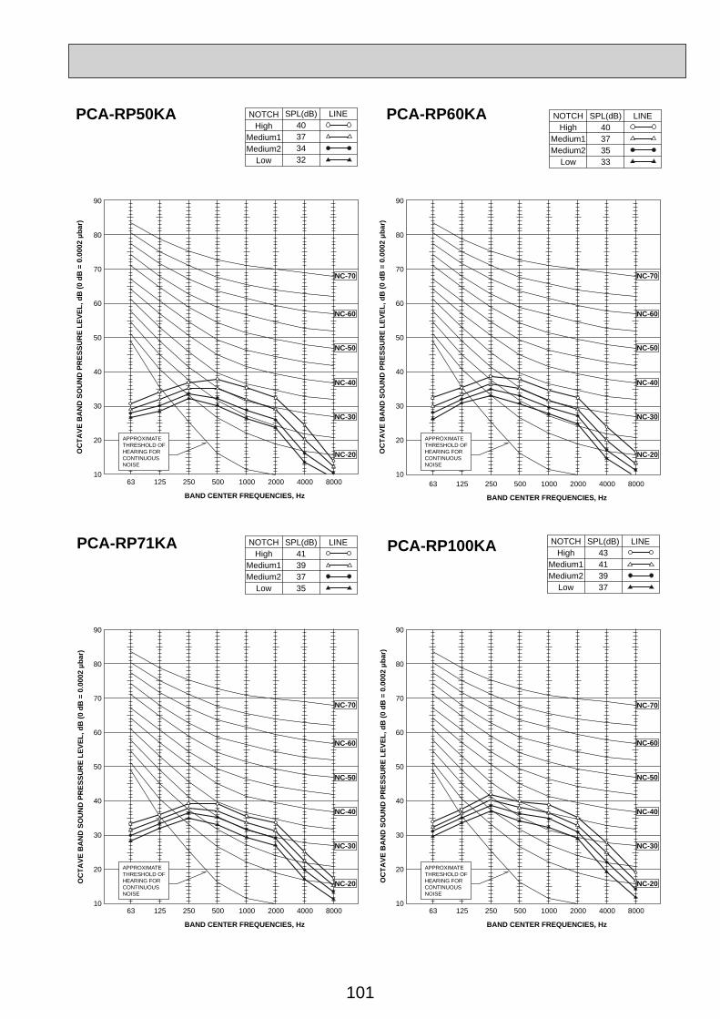
101
90
80
70
60
50
40
30
20
1063 125 250 500 1000 2000 4000 8000
APPROXIMATETHRESHOLD OFHEARING FORCONTINUOUSNOISE
NC-60
NC-50
NC-40
NC-30
NC-20
NC-70
OC
TAVE
BA
ND
SO
UN
D P
RES
SUR
E LE
VEL,
dB
(0 d
B =
0.0
002 μb
ar)
OC
TAVE
BA
ND
SO
UN
D P
RES
SUR
E LE
VEL,
dB
(0 d
B =
0.0
002 μb
ar)
OC
TAVE
BA
ND
SO
UN
D P
RES
SUR
E LE
VEL,
dB
(0 d
B =
0.0
002 μb
ar)
OC
TAVE
BA
ND
SO
UN
D P
RES
SUR
E LE
VEL,
dB
(0 d
B =
0.0
002 μb
ar)
BAND CENTER FREQUENCIES, Hz
NOTCHHigh
Medium1Medium2
Low
SPL(dB)40373432
LINE NOTCHHigh
Medium1Medium2
Low
SPL(dB)40373533
LINE
90
80
70
60
50
40
30
20
1063 125 250 500 1000 2000 4000 8000
APPROXIMATETHRESHOLD OFHEARING FORCONTINUOUSNOISE
NC-60
NC-50
NC-40
NC-30
NC-20
NC-70
BAND CENTER FREQUENCIES, Hz
90
80
70
60
50
40
30
20
1063 125 250 500 1000 2000 4000 8000
APPROXIMATETHRESHOLD OFHEARING FORCONTINUOUSNOISE
NC-60
NC-50
NC-40
NC-30
NC-20
NC-70
BAND CENTER FREQUENCIES, Hz
NOTCHHigh
Medium1Medium2
Low
SPL(dB)41393735
LINE
90
80
70
60
50
40
30
20
1063 125 250 500 1000 2000 4000 8000
APPROXIMATETHRESHOLD OFHEARING FORCONTINUOUSNOISE
NC-60
NC-50
NC-40
NC-30
NC-20
NC-70
BAND CENTER FREQUENCIES, Hz
NOTCHHigh
Medium1Medium2
Low
SPL(dB)43413937
LINE
PCA-RP50KA PCA-RP60KA
PCA-RP71KA PCA-RP100KA
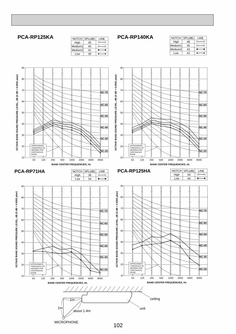
102
1m
1m unitabout 1.4m
MICROPHONE
ceiling
90
80
70
60
50
40
30
20
1063 125 250 500 1000 2000 4000 8000
APPROXIMATETHRESHOLD OFHEARING FORCONTINUOUSNOISE
NC-60
NC-50
NC-40
NC-30
NC-20
NC-70
BAND CENTER FREQUENCIES, Hz
OC
TAVE
BA
ND
SO
UN
D P
RES
SUR
E LE
VEL,
dB
(0 d
B =
0.0
002 μb
ar)
NOTCHHigh
Medium1Medium2
Low
SPL(dB)45434139
LINE
90
80
70
60
50
40
30
20
1063 125 250 500 1000 2000 4000 8000
APPROXIMATETHRESHOLD OFHEARING FORCONTINUOUSNOISE
NC-60
NC-50
NC-40
NC-30
NC-20
NC-70
BAND CENTER FREQUENCIES, Hz
OC
TAVE
BA
ND
SO
UN
D P
RES
SUR
E LE
VEL,
dB
(0 d
B =
0.0
002 μb
ar)
NOTCHHigh
Medium1Medium2
Low
SPL(dB)48454341
LINE PCA-RP125KA PCA-RP140KA
90
80
70
60
50
40
30
20
1063 125 250 500 1000 2000 4000 8000
APPROXIMATETHRESHOLD OFHEARING FORCONTINUOUSNOISE
NC-60
NC-50
NC-40
NC-30
NC-20
NC-70
BAND CENTER FREQUENCIES, Hz
OC
TAVE
BA
ND
SO
UN
D P
RES
SUR
E LE
VEL,
dB
(0 d
B =
0.0
002 μb
ar)
PCA-RP71HA NOTCHHighLow
SPL(dB)3834
LINE
90
80
70
60
50
40
30
20
1063 125 250 500 1000 2000 4000 8000
APPROXIMATETHRESHOLD OFHEARING FORCONTINUOUSNOISE
NC-60
NC-50
NC-40
NC-30
NC-20
NC-70
BAND CENTER FREQUENCIES, Hz
OC
TAVE
BA
ND
SO
UN
D P
RES
SUR
E LE
VEL,
dB
(0 d
B =
0.0
002 μb
ar)
PCA-RP125HA NOTCHHighLow
SPL(dB)5044
LINE
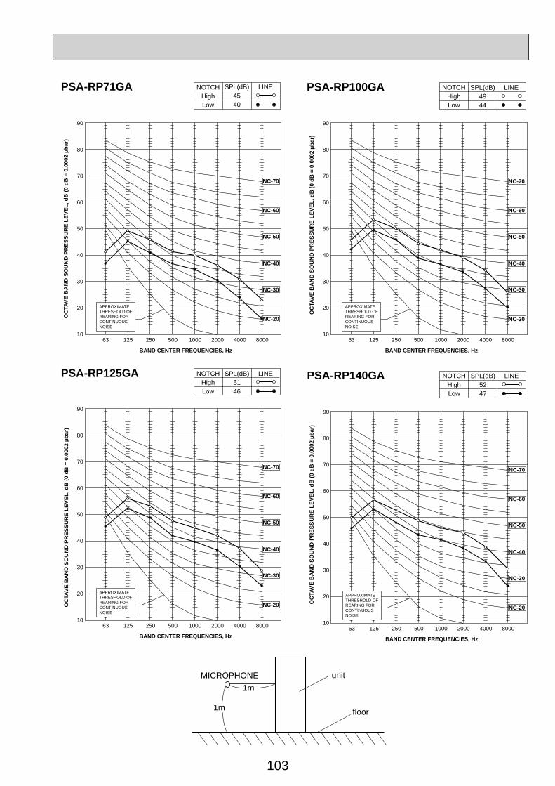
103
90
80
70
60
50
40
30
20
1063 125 250 500 1000 2000 4000 8000
APPROXIMATETHRESHOLD OFREARING FORCONTINUOUSNOISE
NC-60
NC-50
NC-40
NC-30
NC-20
NC-70
BAND CENTER FREQUENCIES, Hz
OC
TAVE
BA
ND
SO
UN
D P
RES
SUR
E LE
VEL,
dB
(0 d
B =
0.0
002 μb
ar)
PSA-RP71GA NOTCHHighLow
SPL(dB)4540
LINE
90
80
70
60
50
40
30
20
1063 125 250 500 1000 2000 4000 8000
APPROXIMATETHRESHOLD OFREARING FORCONTINUOUSNOISE
NC-60
NC-50
NC-40
NC-30
NC-20
NC-70
BAND CENTER FREQUENCIES, Hz
OC
TAVE
BA
ND
SO
UN
D P
RES
SUR
E LE
VEL,
dB
(0 d
B =
0.0
002 μb
ar)
PSA-RP100GA NOTCHHighLow
SPL(dB)4944
LINE
90
80
70
60
50
40
30
20
1063 125 250 500 1000 2000 4000 8000
APPROXIMATETHRESHOLD OFREARING FORCONTINUOUSNOISE
NC-60
NC-50
NC-40
NC-30
NC-20
NC-70
BAND CENTER FREQUENCIES, Hz
OC
TAVE
BA
ND
SO
UN
D P
RES
SUR
E LE
VEL,
dB
(0 d
B =
0.0
002 μb
ar)
PSA-RP125GA NOTCHHighLow
SPL(dB)5146
LINE
90
80
70
60
50
40
30
20
1063 125 250 500 1000 2000 4000 8000
APPROXIMATETHRESHOLD OFREARING FORCONTINUOUSNOISE
NC-60
NC-50
NC-40
NC-30
NC-20
NC-70
BAND CENTER FREQUENCIES, Hz
OC
TAVE
BA
ND
SO
UN
D P
RES
SUR
E LE
VEL,
dB
(0 d
B =
0.0
002 μb
ar)
PSA-RP140GA NOTCHHighLow
SPL(dB)5247
LINE
1m
1m
unitMICROPHONE
floor
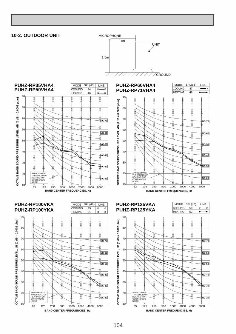
104
10-2. OUTDOOR UNIT
1.5m
1mMICROPHONE
UNIT
GROUND
APPROXIMATETHRESHOLD OFHEARING FORCONTINUOUSNOISE
NC-60
NC-50
NC-40
NC-30
NC-20
NC-70
PUHZ-RP35VHA4PUHZ-RP50VHA4 COOLING
MODE
HEATING44
SPL(dB)
46
LINE
90
80
70
60
50
40
30
20
1063 125 250 500 1000 2000 4000 8000
OC
TAVE
BA
ND
SO
UN
D P
RES
SUR
E LE
VEL,
dB
(0 d
B =
0.0
002 μb
ar)
BAND CENTER FREQUENCIES, Hz
90
80
70
60
50
40
30
20
1063 125 250 500 1000 2000 4000 8000
APPROXIMATETHRESHOLD OFHEARING FORCONTINUOUSNOISE
NC-60
NC-50
NC-40
NC-30
NC-20
NC-70O
CTA
VE B
AN
D S
OU
ND
PR
ESSU
RE
LEVE
L, d
B (0
dB
= 0
.000
2 μb
ar)
BAND CENTER FREQUENCIES, Hz
PUHZ-RP60VHA4PUHZ-RP71VHA4 COOLING
MODE
HEATING47
SPL(dB)
48
LINE
90
80
70
60
50
40
30
20
1063 125 250 500 1000 2000 4000 8000
APPROXIMATETHRESHOLD OFHEARING FORCONTINUOUSNOISE
OC
TAVE
BA
ND
SO
UN
D P
RES
SUR
E LE
VEL,
dB
(0 d
B =
0.0
002 μb
ar)
BAND CENTER FREQUENCIES, Hz
NC-60
NC-50
NC-40
NC-30
NC-20
NC-70
PUHZ-RP100VKAPUHZ-RP100YKA COOLING
MODE
HEATING49
SPL(dB)
51
LINE
90
80
70
60
50
40
30
20
1063 125 250 500 1000 2000 4000 8000
APPROXIMATETHRESHOLD OFHEARING FORCONTINUOUSNOISE
OC
TAVE
BA
ND
SO
UN
D P
RES
SUR
E LE
VEL,
dB
(0 d
B =
0.0
002 μb
ar)
BAND CENTER FREQUENCIES, Hz
NC-60
NC-50
NC-40
NC-30
NC-20
NC-70
PUHZ-RP125VKAPUHZ-RP125YKA COOLING
MODE
HEATING50
SPL(dB)
52
LINE
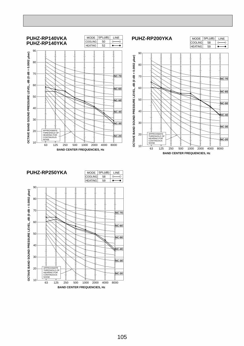
105
90
80
70
60
50
40
30
20
1063 125 250 500 1000 2000 4000 8000
APPROXIMATETHRESHOLD OFHEARING FORCONTINUOUSNOISE
OC
TAVE
BA
ND
SO
UN
D P
RES
SUR
E LE
VEL,
dB
(0 d
B =
0.0
002 μb
ar)
BAND CENTER FREQUENCIES, Hz
NC-60
NC-50
NC-40
NC-30
NC-20
NC-70
PUHZ-RP140VKAPUHZ-RP140YKA COOLING
MODE
HEATING50
SPL(dB)
52
LINE
90
80
70
60
50
40
30
20
1063 125 250 500 1000 2000 4000 8000
APPROXIMATETHRESHOLD OFHEARING FORCONTINUOUSNOISE
OC
TAVE
BA
ND
SO
UN
D P
RES
SUR
E LE
VEL,
dB
(0 d
B =
0.0
002 μb
ar)
BAND CENTER FREQUENCIES, Hz
NC-60
NC-50
NC-40
NC-30
NC-20
NC-70
PUHZ-RP200YKACOOLING
MODE
HEATING58
SPL(dB)
59
LINE
90
80
70
60
50
40
30
20
1063 125 250 500 1000 2000 4000 8000
APPROXIMATETHRESHOLD OFHEARING FORCONTINUOUSNOISE
OC
TAVE
BA
ND
SO
UN
D P
RES
SUR
E LE
VEL,
dB
(0 d
B =
0.0
002 μb
ar)
BAND CENTER FREQUENCIES, Hz
NC-60
NC-50
NC-40
NC-30
NC-20
NC-70
PUHZ-RP250YKACOOLING
MODE
HEATING58
SPL(dB)
59
LINE
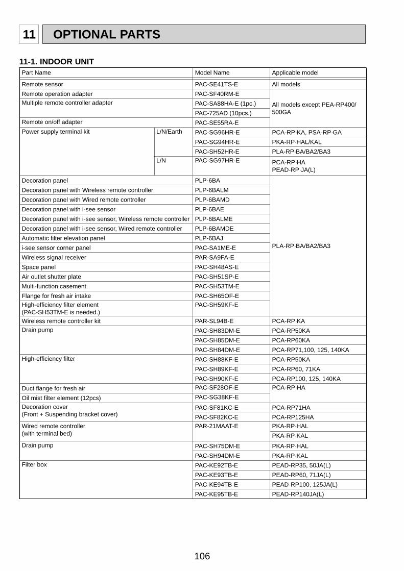
106
11 OPTIONAL PARTS
11-1. INDOOR UNITPart Name Model Name Applicable model
Remote sensor PAC-SE41TS-E All modelsRemote operation adapter PAC-SF40RM-E
All models except PEA-RP400/500GA
Multiple remote controller adapter PAC-SA88HA-E (1pc.)PAC-725AD (10pcs.)
Remote on/off adapter PAC-SE55RA-EPower supply terminal kit L/N/Earth PAC-SG96HR-E PCA-RP·KA, PSA-RP·GA
PAC-SG94HR-E PKA-RP·HAL/KALPAC-SH52HR-E PLA-RP·BA/BA2/BA3
L/N PAC-SG97HR-E PCA-RP·HAPEAD-RP·JA(L)
Decoration panel PLP-6BA
PLA-RP·BA/BA2/BA3
Decoration panel with Wireless remote controller PLP-6BALMDecoration panel with Wired remote controller PLP-6BAMDDecoration panel with i-see sensor PLP-6BAEDecoration panel with i-see sensor, Wireless remote controller PLP-6BALMEDecoration panel with i-see sensor, Wired remote controller PLP-6BAMDEAutomatic fi lter elevation panel PLP-6BAJi-see sensor corner panel PAC-SA1ME-EWireless signal receiver PAR-SA9FA-ESpace panel PAC-SH48AS-EAir outlet shutter plate PAC-SH51SP-EMulti-function casement PAC-SH53TM-EFlange for fresh air intake PAC-SH65OF-EHigh-effi ciency fi lter element (PAC-SH53TM-E is needed.)
PAC-SH59KF-E
Wireless remote controller kit PAR-SL94B-E PCA-RP·KADrain pump PAC-SH83DM-E PCA-RP50KA
PAC-SH85DM-E PCA-RP60KAPAC-SH84DM-E PCA-RP71,100, 125, 140KA
High-effi ciency fi lter PAC-SH88KF-E PCA-RP50KAPAC-SH89KF-E PCA-RP60, 71KAPAC-SH90KF-E PCA-RP100, 125, 140KA
Duct fl ange for fresh air PAC-SF28OF-E PCA-RP·HA
Oil mist fi lter element (12pcs) PAC-SG38KF-EDecoration cover(Front + Suspending bracket cover)
PAC-SF81KC-E PCA-RP71HAPAC-SF82KC-E PCA-RP125HA
Wired remote controller(with terminal bed)
PAR-21MAAT-E PKA-RP·HALPKA-RP·KAL
Drain pump PAC-SH75DM-E PKA-RP·HALPAC-SH94DM-E PKA-RP·KAL
Filter box PAC-KE92TB-E PEAD-RP35, 50JA(L)PAC-KE93TB-E PEAD-RP60, 71JA(L)PAC-KE94TB-E PEAD-RP100, 125JA(L)PAC-KE95TB-E PEAD-RP140JA(L)

107
11-2. OUTDOOR UNIT
Part Name Model Name Applicable model
M-NET adapter PAC-SF81MA-E PUHZ-RP35-250A-control service tool PAC-SK52ST PUHZ-RP35-250Drain socket PAC-SG61DS-E PUHZ-RP35-250
Air outlet guide (RP100-250 need 2 pieces.)PAC-SG58SG-E PUHZ-RP35, 50PAC-SG59SG-E PUHZ-RP60, 71PAC-SH96SG-E PUHZ-RP100-250
Air protect guide (RP100-250 need 2 pieces.)PAC-SG56AG-E PUHZ-RP35, 50PAC-SH63AG-E PUHZ-RP60, 71PAC-SH95AG-E PUHZ-RP100-250
Drain pan PAC-SG63DP-E PUHZ-RP35, 50PAC-SG64DP-E PUHZ-RP60, 71PAC-SH97DP-E PUHZ-RP100-250
Filter dryer ([6.35) PAC-SG81DR-E PUHZ-RP35, 50([9.52) PAC-SG82DR-E PUHZ-RP60-200([12.7) PAC-SG85DR-E PUHZ-RP250
Distribution pipe (Twin) MSDD-50TR-E PUHZ-RP71-140MSDD-50WR-E PUHZ-RP200, 250
(Triple) MSDT-111R-E PUHZ-RP140-250(Quadruple) MSDF-1111R-E PUHZ-RP200, 250
Joint pipe (Unit Extension pipe) ([15.88 [19.05) PAC-SG75RJ-E PUHZ-RP60-140([9.52 [12.7) PAC-SG73RJ-E PUHZ-RP60-200([12.7 [15.88) PAC-SG74RJ-E PUHZ-RP250([6.35 [9.52) PAC-SG72RJ-E PUHZ-RP35-50

HEAD OFFICE : TOKYO BLDG., 2-7-3, MARUNOUCHI, CHIYODA-KU, TOKYO 100-8310, JAPAN
CCopyright 2009 MITSUBISHI ELECTRIC ENGINEERING CO., LTD.Distributed in Jul. 2009 No.OCS16 PDF 6Made in Japan
New publication, effective Jul. 2009Specifications subject to change without notice.
TM