Embed Size (px)
Citation preview
Association of Radio Industries and Businesses (ARIB)
VERSION 1.00
ARIB TR-T15
ISSUED June 20, 2000
RCR STD-28
Technical Report of Mobile Satellite System consideration for 3G Mobile System
Association of Radio Industries and Businesses (ARIB )
ARIB TR-T15
Technical Report of Mobile Satellite System
consideration for 3G Mobile System
ARIB TECHNICAL REPORT
Ver.1.00 ARIB TR-T15
ARIB TECHNICAL REPORT

ARIB TR-T15
i
Table of Contents for ARIB TR-T15 Technical Report of Mobile Satellite System consideration
for 3G Mobile System
Foreword
1. INTRODUCTION ........................................................................................................................................... 1 1.1 Scope ....................................................................................................................................................... 1 1.2 Definitions and Terminology ................................................................................................................ 2 1.3 Reference ................................................................................................................................................ 2 1.4 Detail of the ITU-R Recommendations for IMT-2000 ....................................................................... 6
2. REQUIREMENT & OBJECTIVE .............................................................................................................. 11
2.1 General Requirement and Objective ................................................................................................. 11
2.1.1 General Objectives ...................................................................................................................... 11 2.1.2 General Objectives related to commonalties between Satellite and Terrestrial System ....... 12 2.1.3 General Objectives of Service Configuration ........................................................................... 13
2.2 Service Requirements.......................................................................................................................... 15
2.2.1 Basic Telecommunication Services............................................................................................. 15 2.2.2 Teleservices................................................................................................................................... 15
2.2.2.1 Telephony ............................................................................................................................ 15 2.2.2.2 Voice Band Data Services.................................................................................................... 15 2.2.2.3 Facsimile ............................................................................................................................. 16 2.2.2.4 Other Teleservices ............................................................................................................... 16
2.2.3 Bearer Services ............................................................................................................................ 16
2.2.3.1 Bearer Service Description.................................................................................................. 16
2.2.3.1.1 Information transfer attributes .................................................................................... 17 2.2.3.1.2 Information quality attributes ..................................................................................... 17
2.2.3.2 Supported bit rates ............................................................................................................... 17 2.2.3.3 Supported Qos ..................................................................................................................... 18 2.2.3.4 Supported topologies ........................................................................................................... 19 2.2.3.5 Radio Interface optimization ............................................................................................... 19
2.2.4 Supplementary Services.............................................................................................................. 19 2.2.5 Mobile Specific Service ............................................................................................................... 20
ARIB TR-T15
ii
2.2.5.1 High Penetration Message Service (i.e. Paging).................................................................. 20 2.2.5.2 Short Message ..................................................................................................................... 20 2.2.5.3 Specific Dispatch Services (Group Call, Broadcast Call, Selective Broadcast Call etc.) ............................................. 20
2.2.6 IP Based Services......................................................................................................................... 20 2.2.7 Services to be considered for Later Phase ................................................................................. 20
2.2.7.1 Service Requirements for IMT-2000 Mobile Satellite System Phase 1 .............................. 20 2.2.7.2 Services to be considered for later phases ........................................................................... 21
2.3 Access Requirement ................................................................................................................................ 22 2.4 User Mobility ........................................................................................................................................... 23
2.4.1 Terminal Mobility........................................................................................................................ 23 2.4.2 User Mobility ............................................................................................................................... 23
2.5 Roaming and Handover ...................................................................................................................... 23
2.5.1 Roaming ....................................................................................................................................... 23
2.5.1.1 Support between IMT-2000 Terrestrial System................................................................... 23 2.5.1.2 Physical Radio Interface Compatibility............................................................................... 23
2.5.2 Handover...................................................................................................................................... 23
2.5.2.1 Support of Handover ........................................................................................................... 23 2.5.2.2 Types of Handover............................................................................................................... 24 2.5.2.3 Seamless Handover ............................................................................................................. 24 2.5.2.4 Signalling Load of Handover .............................................................................................. 24
2.6 Hand-portable Viability Requirements ................................................................................................. 25
2.7 Required Bearer Channel Capabilities.................................................................................................. 25 2.8 Quality of Service .................................................................................................................................... 26
2.8.1 General ........................................................................................................................................... 26
2.8.1.1 Speech quality ..................................................................................................................... 26 2.8.1.2 Connection performance...................................................................................................... 26 2.8.1.3 Service retainability performance........................................................................................ 26 2.8.1.4 Reliability performance ....................................................................................................... 26
2.8.2 Overview of Different Levels of Quality of Service (QoS) ....................................................... 26 2.8.3 IMT-2000 QoS Classes ................................................................................................................ 27 2.8.4 Range of QoS requirements........................................................................................................ 27
2.8.4.1 Supported End User QoS..................................................................................................... 28
ARIB TR-T15
iii
2.8.4.2 Principal speech quality requirements ................................................................................. 28
2.8.4.2.1 Subjective quality ....................................................................................................... 28 2.8.4.2.2 Loss of interactivity due to delay in the speech path .................................................. 28
2.8.5 Uniformity in different environments........................................................................................ 29 2.8.6 Effects of transcoding.................................................................................................................. 29 2.8.7 Quality of end-to-end connections ............................................................................................. 29 2.8.8 Gross speech bit rate ................................................................................................................... 29 2.8.9 Interconnection of IMT-2000 users in different networks....................................................... 29 2.8.10 Principal voiceband data requirements ....................................................................................... 29
2.8.10.1 DTMF signalling requirements ........................................................................................... 29 2.8.10.2 Voiceband data requirements............................................................................................... 30
2.8.11 Radio performance requirements ................................................................................................ 30
2.8.11.1 Speech quality requirements................................................................................................ 30
2.9 Spectrum Requirements ......................................................................................................................... 30
2.9.1 Background .................................................................................................................................. 30 2.9.2 Revision of Spectrum Requirements.......................................................................................... 31 2.9.3 Service and data rates ................................................................................................................. 32 2.9.4 Market considerations for satellite component......................................................................... 32
2.10 Software Download (To be added) ......................................................................................................... 32
2.10.1 Mobile Initiated ............................................................................................................................. 32 2.10.2 User Data........................................................................................................................................ 32
2.11 Security and Privacy (To be added) ....................................................................................................... 32
2.11.1 High-level Requirement for Security and Private ...................................................................... 33 2.11.2 Security and Privacy Feature ....................................................................................................... 33
2.11.2.1 Access Control for Subscription and Service Profile Data.................................................. 33 2.11.2.2 User Identity Authentication ............................................................................................... 33 2.11.2.3 UIM Holder Verification ..................................................................................................... 33 2.11.2.4 User Data Confidentially ..................................................................................................... 33 2.11.2.5 Signalling Information Confidentiality................................................................................ 33 2.11.2.6 User Identity Confidentiality ............................................................................................... 34 2.11.2.7 User Location Confidentiality ............................................................................................. 34 2.11.2.8 Network Operator/Service Provider Authentication............................................................ 34 2.11.2.9 Re-authentication of User.................................................................................................... 34 2.11.2.10 Subscriber Access to Service............................................................................................... 34 2.11.2.11 Version Control of Security Data and Mechanisms............................................................. 34
2.12 Safety and EMC Requirement (To be added) ....................................................................................... 34
ARIB TR-T15
iv
2.12.1 Safety Requirement ....................................................................................................................... 34 2.12.2 Electromagnetic Compatibility..................................................................................................... 34
2.13 Requirement for Interference with Other Systems .............................................................................. 34
2.13.1 Interference to and from satellites ............................................................................................... 34 2.13.2 Interference between mobile earth stations (MESs) and Other Systems ................................. 35
2.14 Location Services ..................................................................................................................................... 36
APPENDIX USA FCC Wireless E911 Rules..................................................37
3. Consideration of Satellite Operating Environment.................................................................................... 38
3.1 Radio Operating Environment............................................................................................................... 38
3.1.1 Urban satellite environment ....................................................................................................... 38 3.1.2 Rural satellite environment ........................................................................................................ 38 3.1.3 Satellite fixed-mounted environment......................................................................................... 38 3.1.4 Indoor satellite environment ...................................................................................................... 39
3.2 Transmission Range and Satellite Constellations ................................................................................. 39
3.2.1 Maximum transmission range.................................................................................................... 39 3.2.2 Overall path loss prediction models........................................................................................... 39
3.3 Propagation Delay and Doppler Variation ............................................................................................ 39
3.3.1 Multipath delay spreads.............................................................................................................. 39 3.3.2 Maximum Doppler shifts ............................................................................................................ 39
3.4 Propagation Models and Fading ............................................................................................................ 40
3.4.1 Narrowband model...................................................................................................................... 40 3.4.2 Wideband model.......................................................................................................................... 41 3.4.3 Description of Doppler spectra................................................................................................... 41 3.4.4 Parameters of the wideband models .......................................................................................... 42
APPENDIX Computation of Doppler shift for satellites ..................................44
4. Overview of MSS Radio Interface ............................................................................................................... 46
4.1 Selection of Radio Transmission System ............................................................................................... 46
4.1.1 Key Parameters for Selecting the Radio Transmission System............................................... 46
4.1.1.1 Support of Wide Rang of Data speed .................................................................................. 46 4.1.1.2 Support Connectionless Communication ............................................................................ 46 4.1.1.3 Commonality between IMT-2000 Terrestrial Mobile System(s)......................................... 46
ARIB TR-T15
v
4.1.2 Selection of CDMA as the Radio Transmission Technology .................................................... 47
4.2 Technical Requirements for 3G Mobile Satellite Systems ................................................................... 48
4.2.1 Technical Requirement to Satisfy Minimum Requirements.................................................... 48
4.2.1.1 Definition of Minimum Requirements ................................................................................ 48 4.2.1.2 Operating Condition of Mobile Earth Stations .................................................................... 49 4.2.1.3 Channel capacity ................................................................................................................. 50
4.2.2 Technical Requirement for Onboard Equipment..................................................................... 50
4.3 Frequency Reuse Plan ............................................................................................................................. 53
4.3.1 Uniform Cell-Size Approach ...................................................................................................... 53 4.3.2 Selection of Frequency Reuse Pattern ....................................................................................... 53 4.3.3 Channel Capacity Evaluation..................................................................................................... 54
4.4 Consideration of Orbit and Satellite Constellation .............................................................................. 56
4.4.1 Type of MSS ................................................................................................................................. 56
4.4.1.1 GSO ..................................................................................................................................... 56 4.4.1.2 NGSO .................................................................................................................................. 56
4.4.2 Description of Satellite Topologies for NGSO ........................................................................... 56
4.4.2.1 Two types of Constellations (π-constellation and 2π-constellation) ................................... 56 4.4.2.2 Beam Allocation.................................................................................................................. 57
4.4.2.2.1 π-constellation ............................................................................................................ 57 4.4.2.2.2 2π-constellation .......................................................................................................... 58
4.4.2.2.2.1 Independent global coverage in two satellite groups .......................................... 58 4.4.2.2.2.2 Covered by at least one satellite.......................................................................... 58
4.5 Radio System Design Specific to Satellite Operating Environment .................................................... 59
4.5.1 Delay Analysis.............................................................................................................................. 59
4.5.1.1 Tele services ........................................................................................................................ 59
4.5.1.1.1 Telephony services...................................................................................................... 59 4.5.1.1.2 Voice band Data Service ............................................................................................. 61 4.5.1.1.3 Group 3 Facsimile Service.......................................................................................... 61 4.5.1.1.4 Other Teleservices....................................................................................................... 61
4.5.1.2 Bearer Service ..................................................................................................................... 61 4.5.1.3 IP based Service .................................................................................................................. 61
ARIB TR-T15
vi
4.5.2 Power Control.............................................................................................................................. 62
4.5.2.1 Required Range of Transmitting Power Control ................................................................. 62 4.5.2.2 Transmit Power Control Error ............................................................................................. 62
4.5.3 Compensation of Frequency Deviation Caused by Doppler Shift........................................... 63
4.5.3.1 Doppler Shift Buffer for Clock Timing ............................................................................... 63 4.5.3.2 Phase lock for Carrier Recovery.......................................................................................... 63 4.5.3.3 Estimate Doppler shifts from Satellite orbit ........................................................................ 63
4.5.4 Synchronization ........................................................................................................................... 63
4.5.4.1 Channel Synchronization..................................................................................................... 63 4.5.4.2 Cell Synchronization ........................................................................................................... 63 4.5.4.3 Adjacent Satellite Synchronization...................................................................................... 64 4.5.4.4 Synchronization Procedures ................................................................................................ 64
4.5.5 Consideration of Low Layer Protocol Specific to Satellite Environment............................... 64
4.6 Satellite Radio Access Network Interface Architecture ....................................................................... 65 4.7 Channel Structure ................................................................................................................................... 68 4.8 Multiple Access Scheme .......................................................................................................................... 71
4.8.1 Multi-channel Access Operation ................................................................................................ 71 4.8.2 Duplex Operation (FDD and TDD Mode Operation) .............................................................. 71 4.8.3 Packet Data Access ...................................................................................................................... 72
4.9 Modulation and Coding .......................................................................................................................... 73
4.9.1 Coding and Interleaving ............................................................................................................. 73 4.9.2 Spreading and Modulation ......................................................................................................... 74 4.9.3 Consideration for Coherent Detection....................................................................................... 75 4.9.4 Consideration for Pilot Signal Power ........................................................................................ 75
4.10 Multi-Satellite Scenarios ......................................................................................................................... 76
4.10.1 Interference considerations ........................................................................................................ 76 4.10.2 Satellite diversity and inter-satellite handover ......................................................................... 77
4.11 Inter-Operability with Terrestrial System ............................................................................................ 80
4.11.1 Inter-Operability of terminals.................................................................................................... 80 4.11.2 Inter-Operability with terrestrial network ............................................................................... 80
4.12 Location Determination Methods for Location Services ..................................................................... 82 4.13 Radio Channel Reference Circuit .......................................................................................................... 83
ARIB TR-T15
vii
ANNEX 1 Description of Teleservices and Specific Dispatch Services ......................................................... 1 ANNEX 2 Consideration of Voice CODEC ..................................................................................................... 2 ANNEX 3 Reference Model and Calculation Method for Section 4.2 and 4.3 ............................................. 3 ANNEX 4 Evaluation of Channel Capacity .................................................................................................. 19 ANNEX 5 Summary of IMT-2000 Radio Transmission Technology for Satellite Environment .............. 29 ANNEX 6 Terminologies and Abbreviations................................................................................................. 34
Foreword
This Technical Report was produced by Satellite Working Group of ARIB IMT-2000 Study Committee.
The Satellite Working Group considered as follows:
- ITU-R recommendations related to the IMT-2000 have been studied in detailed regarding the requirement and
framework as major points.
- The ITU-R recommendations of the concrete IMT-2000 systems have been developed by the Standard
Development Organizations (SDO).
- Several proponents of IMT-2000 MSS have been proposed and the recommendations of IMT-2000 MSS have
been also developed but no implementation plan of the proposed IMT-2000 exists so far. Also, there is no plan to
realize the IMT-2000 MSS in Japan as of June, 2000.
- The requirements and specifications of IMT-2000 terrestrial systems are defined and cleared.
- The ITU-R decided that the new proponent of IMT-2000 MSS can be proposed and the proposed IMT-2000
MSS can be modified after year 2000.
The Satellite Working Group decided as follows:
- We took a step toward technical reports beyond the ITU recommendations related to IMT-2000 MSS under the
above considerations, and summarized the necessary items to be required for the development of concrete
IMT-2000 MSS.
- In summarizing of the IMT-2000 MSS, following items are noted.
- The compatibility between the IMT-2000 terrestrial system and IMT-2000 MSS should be the most
important matter is considered in this document.
- The requirements of IMT-2000 MSS are mainly referred from ITU-R Recommendations and 3GPP
specifications.
- The technical requirements of IMT-2000 MSS are brought by the discussions in the Satellite Working Group.
AIRB TR-T15
1
1. Introduction 1.1 Scope IMT-2000 is the ITU defined third generation mobile system concept. IMT-2000 is scheduled by ITU to start service around the year 2001 subject to market needs considerations. They will provide access, by means of one or more radio links, to a wide range of telecommunication services supported by the fixed telecommunication networks (e.g. PSTN/ISDN) and Internet, and to other services which are specific to mobile users. The IMT-2000 terrestrial component will not be able to provide global coverage, and large geographic areas will remain without terrestrial coverage. The satellite component will provide IMT-2000 services in these geographic areas. Of the population within terrestrial coverage, some IMT-2000 users will travel for both business and pleasure, to areas without terrestrial coverage. The high penetration expected for IMT-2000 means that some users will want communications with high mobility at anytime and everywhere they travel. It is only through the combination of IMT-2000 terrestrial and satellite components that true global coverage can be accomplished for key features. Therefore, the required key features of IMT-2000 satellite components are high degree of commonality with IMT-2000 terrestrial components, compatibility of services with IMT-2000 terrestrial components and with fixed network. In addition, use of a small sized terminal with world-wide roaming capability using multi-mode function, high quality and capability for multimedia applications and a wide range of services are also expected for key features. At WARC-92, 60 MHz of spectrum was identified for IMT-2000 MSS in Radio Regulations. However, the expected demand for additional IMT-2000 MSS spectrum after initial deployment have to be considered due to the growth in satellite mobile communications, has been discussed at ITU-R TG8/1 meetings. The TG8/1 made the proposed text for CPM report to WRC-2000 at 16th meeting(8-9 March 1999, Fortaleza, Brazil) of TG8/1, which indicates that an additional allocation for MSS of 2 x 67 MHz would be required by 2010. An important factor when looking at spectrum for mobile satellite systems is the system replacement and evolution. Satellite systems equipment needs to be replaced after for ages, however, replacement of this equipment is inherently a long-term process and can be difficult to accomplish. Therefore, satellite's RTT for future satellite IMT-2000 systems will require substantial planning, investment and long-term vision with the operators. Ideally one RTT, encompassing all environments (satellite, cellular, cordless , WILL) and all regions should be considered. In ITU-R TG8/1, the majority of opinions regarding the harmonisation for RTTs of IMT-2000 MSS is that there is no need to agree on a single RTT. Global/regional and transparent/regenerative systems may favour different solutions. However, there are needs for which, open (not proprietary) RTT to ease competition/access in/to the satellite component, open standard to ensure efficient exploitation of spectrum resources, ensure the commonality with terrestrial system to maximise spin-off and to make cheaper/smaller dual-mode terminals. Therefore, from the above view points, the scope of this document covers requirements and objectives, satellite operating environments, overview of radio interface, guideline of satellite radio interface layer 1, consideration to upper layer radio interface of satellite components and network interface and coordination to other systems of a IMT-2000 Mobile System.
AIRB TR-T15
2
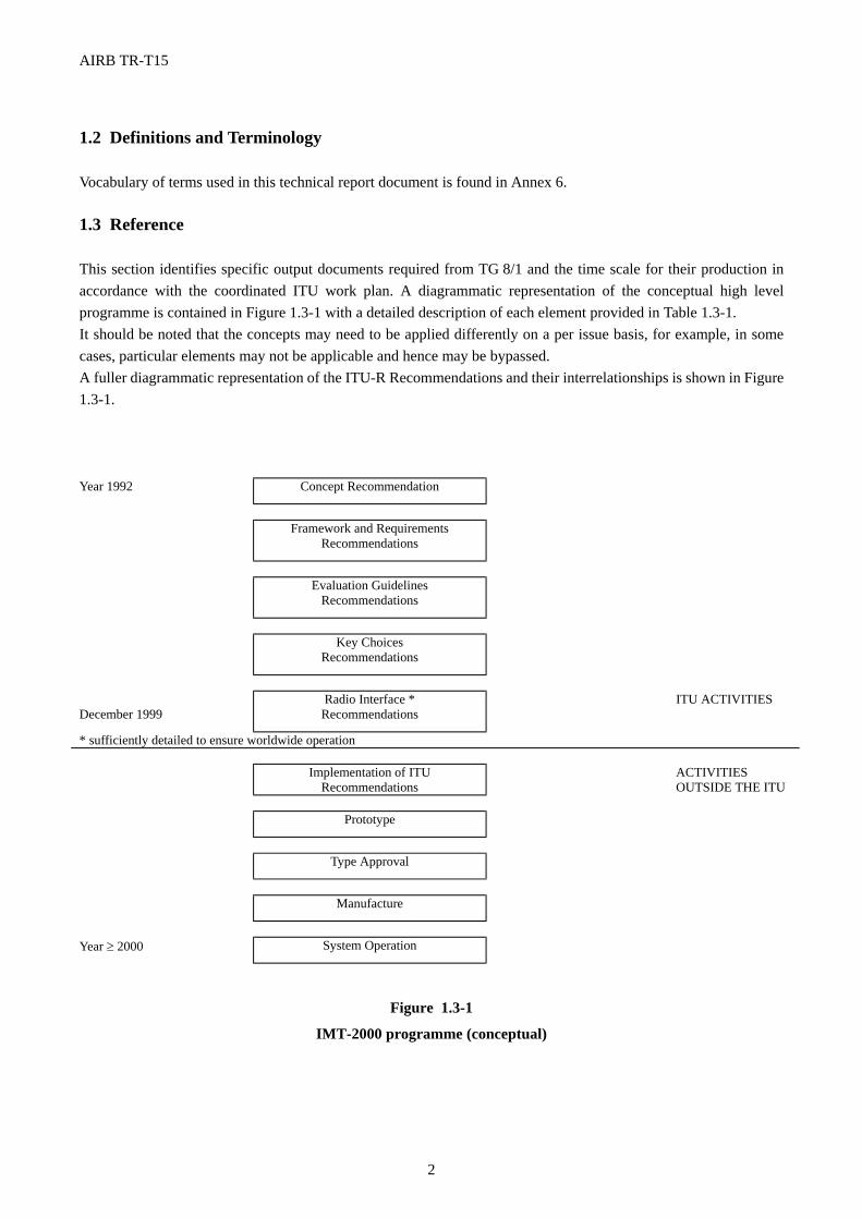
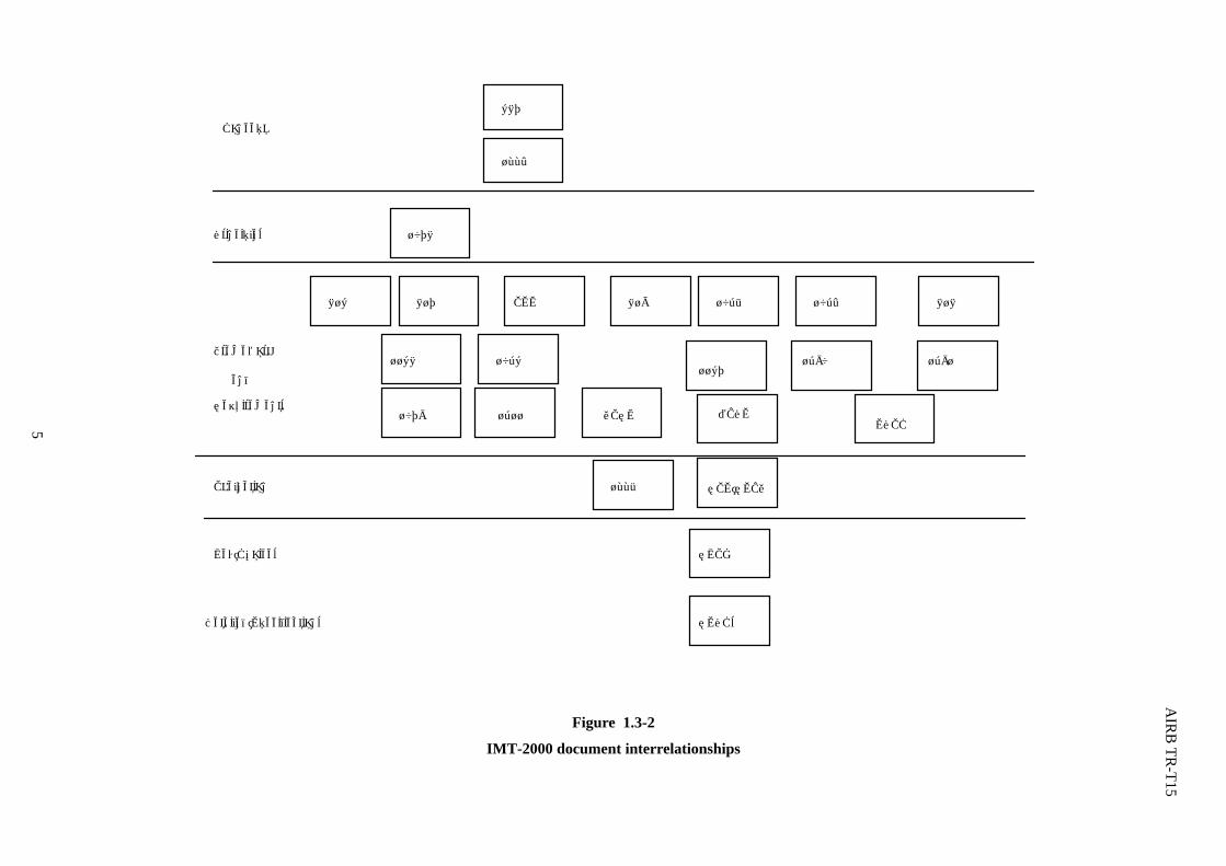
1.2 Definitions and Terminology Vocabulary of terms used in this technical report document is found in Annex 6. 1.3 Reference This section identifies specific output documents required from TG 8/1 and the time scale for their production in accordance with the coordinated ITU work plan. A diagrammatic representation of the conceptual high level programme is contained in Figure 1.3-1 with a detailed description of each element provided in Table 1.3-1. It should be noted that the concepts may need to be applied differently on a per issue basis, for example, in some cases, particular elements may not be applicable and hence may be bypassed. A fuller diagrammatic representation of the ITU-R Recommendations and their interrelationships is shown in Figure 1.3-1. Year 1992 Concept Recommendation
Framework and Requirements
Recommendations
Evaluation Guidelines Recommendations
Key Choices Recommendations
December 1999
Radio Interface * Recommendations
ITU ACTIVITIES
* sufficiently detailed to ensure worldwide operation Implementation of ITU
Recommendations ACTIVITIES
OUTSIDE THE ITU Prototype
Type Approval
Manufacture
Year ≥ 2000 System Operation
Figure 1.3-1
IMT-2000 programme (conceptual)
AIRB TR-T15
3
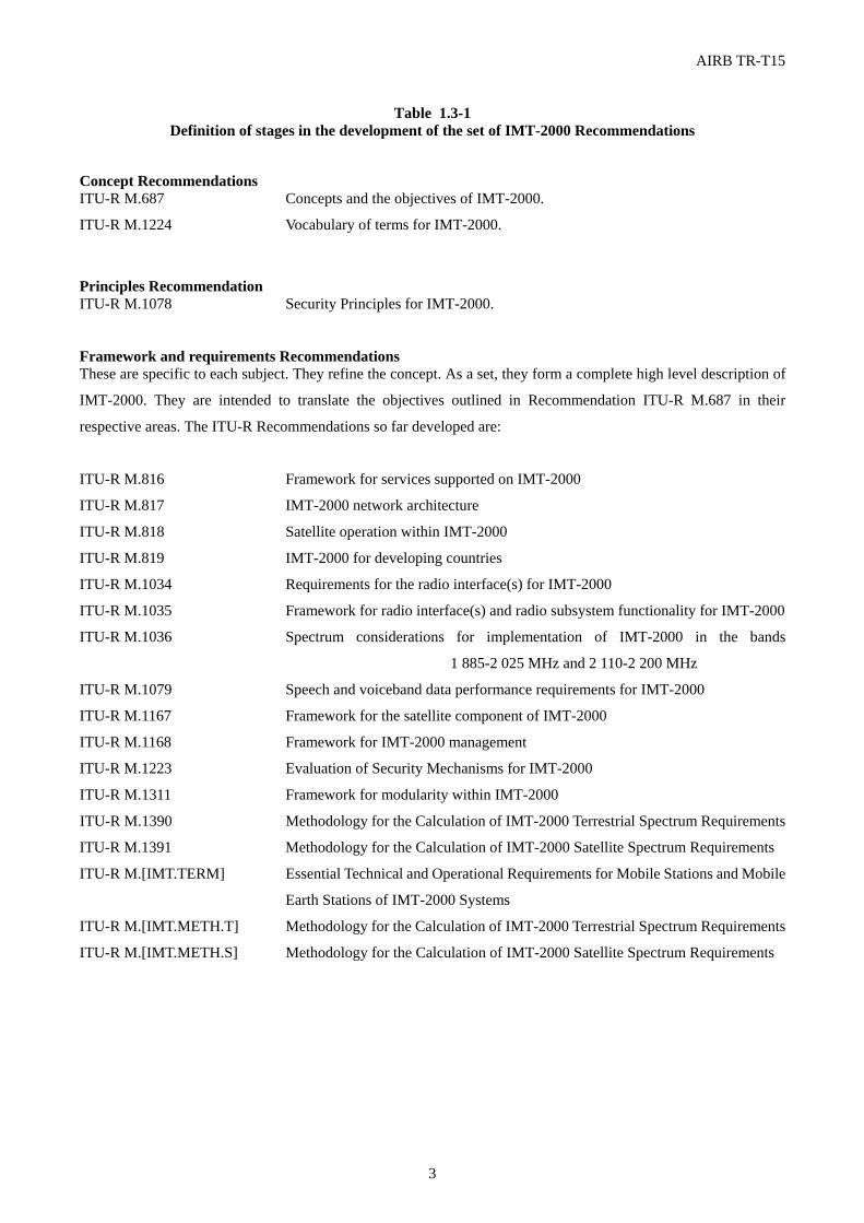
Table 1.3-1 Definition of stages in the development of the set of IMT-2000 Recommendations
Concept Recommendations ITU-R M.687 Concepts and the objectives of IMT-2000.
ITU-R M.1224 Vocabulary of terms for IMT-2000.
Principles Recommendation ITU-R M.1078 Security Principles for IMT-2000. Framework and requirements Recommendations These are specific to each subject. They refine the concept. As a set, they form a complete high level description of
IMT-2000. They are intended to translate the objectives outlined in Recommendation ITU-R M.687 in their
respective areas. The ITU-R Recommendations so far developed are:
ITU-R M.816 Framework for services supported on IMT-2000
ITU-R M.817 IMT-2000 network architecture
ITU-R M.818 Satellite operation within IMT-2000
ITU-R M.819 IMT-2000 for developing countries
ITU-R M.1034 Requirements for the radio interface(s) for IMT-2000
ITU-R M.1035 Framework for radio interface(s) and radio subsystem functionality for IMT-2000
ITU-R M.1036 Spectrum considerations for implementation of IMT-2000 in the bands
1 885-2 025 MHz and 2 110-2 200 MHz
ITU-R M.1079 Speech and voiceband data performance requirements for IMT-2000
ITU-R M.1167 Framework for the satellite component of IMT-2000
ITU-R M.1168 Framework for IMT-2000 management
ITU-R M.1223 Evaluation of Security Mechanisms for IMT-2000
ITU-R M.1311 Framework for modularity within IMT-2000
ITU-R M.1390 Methodology for the Calculation of IMT-2000 Terrestrial Spectrum Requirements
ITU-R M.1391 Methodology for the Calculation of IMT-2000 Satellite Spectrum Requirements
ITU-R M.[IMT.TERM] Essential Technical and Operational Requirements for Mobile Stations and Mobile
Earth Stations of IMT-2000 Systems
ITU-R M.[IMT.METH.T] Methodology for the Calculation of IMT-2000 Terrestrial Spectrum Requirements
ITU-R M.[IMT.METH.S] Methodology for the Calculation of IMT-2000 Satellite Spectrum Requirements
AIRB TR-T15
4
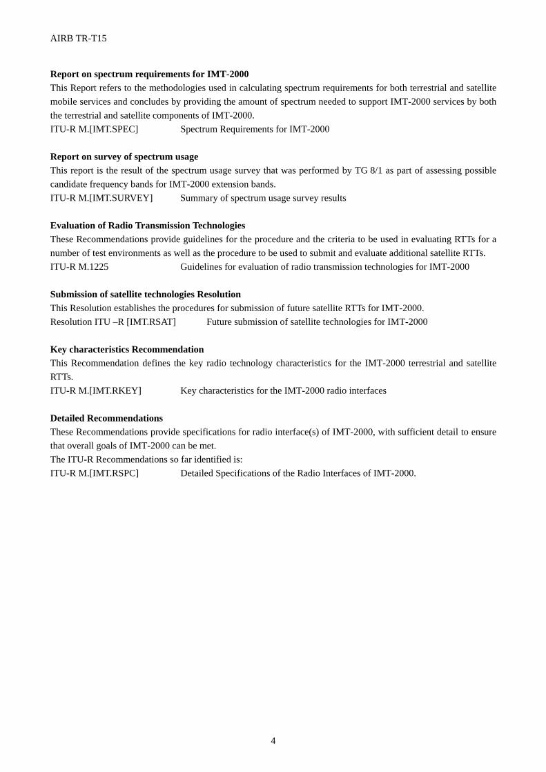
Report on spectrum requirements for IMT-2000 This Report refers to the methodologies used in calculating spectrum requirements for both terrestrial and satellite mobile services and concludes by providing the amount of spectrum needed to support IMT-2000 services by both the terrestrial and satellite components of IMT-2000. ITU-R M.[IMT.SPEC] Spectrum Requirements for IMT-2000 Report on survey of spectrum usage This report is the result of the spectrum usage survey that was performed by TG 8/1 as part of assessing possible candidate frequency bands for IMT-2000 extension bands. ITU-R M.[IMT.SURVEY] Summary of spectrum usage survey results
Evaluation of Radio Transmission Technologies These Recommendations provide guidelines for the procedure and the criteria to be used in evaluating RTTs for a number of test environments as well as the procedure to be used to submit and evaluate additional satellite RTTs. ITU-R M.1225 Guidelines for evaluation of radio transmission technologies for IMT-2000 Submission of satellite technologies Resolution This Resolution establishes the procedures for submission of future satellite RTTs for IMT-2000. Resolution ITU –R [IMT.RSAT] Future submission of satellite technologies for IMT-2000 Key characteristics Recommendation This Recommendation defines the key radio technology characteristics for the IMT-2000 terrestrial and satellite RTTs. ITU-R M.[IMT.RKEY] Key characteristics for the IMT-2000 radio interfaces
Detailed Recommendations These Recommendations provide specifications for radio interface(s) of IMT-2000, with sufficient detail to ensure that overall goals of IMT-2000 can be met. The ITU-R Recommendations so far identified is: ITU-R M.[IMT.RSPC] Detailed Specifications of the Radio Interfaces of IMT-2000.
AIR
B TR
-T15
5
C oncept
R SPC sD etailed Specifications
1078
816 817 ESM 819 818
11681167
10341035
1036
1079
R KEY
Evaluation
Key C hoices
Fram ew ork
and
R equirem ents
Principles
1225
687
1224
1311 TER MSPEC
1390 1391
H APS
R ES R SAT
Figure 1.3-2
IMT-2000 document interrelationships
AIRB TR-T15
6
1.4 Detail of the ITU-R Recommendations for IMT-2000 Scope statements of the various ITU-R Recommendations are as follows; Recommendation ITU-R M.687-2 - International Mobile Telecommunications-2000 Starting from Questions ITU-R 39/8 and ITU-R 77/1, Recommendation ITU-R M.687-1 defines the objectives to be met by IMT-2000 and provides the overall IMT-2000 concepts with particular consideration to achieving worldwide roaming and compatibility. This Recommendation provides a high level statement on the topics of: services, architecture, network aspects, implementation, sharing, and operational characteristics. Guidance is provided, for a limited number of possible scenarios, on spectrum bandwidth and band of operation based on critical technical parameters and traffic estimates. It forms a foundation for the subject of IMT-2000 and for the subsequent work activities and Recommendations.
Recommendation ITU-R M.816-1 - Framework for Services Supported by IMT-2000 This Recommendation forms a framework for continued development towards detailed IMT-2000 service descriptions such as ITU-T Recommendation F.115. A phased approach is adopted for the definition of IMT-2000. In this Recommendation the services required for Phase 1 are described, and an outline of the services for Phase 2 is also given. Phase 1 includes those services supported by user bit rates up to approximately 2 Mbit/s. Phase 2 is envisaged as augmenting Phase 1 with new services, some of which may require higher bit rates.
Recommendation ITU-R M.817 - IMT-2000 Network Architectures This Recommendation presents the functional network architectures and some of the resulting network configurations which are possible for IMT-2000. It should form the basis for defining the information flows within IMT-2000.
Recommendation ITU-R M.818 - Satellite Operation within IMT-2000 The Recommendation provides high level guidance on the integration of the satellite component into IMT-2000. In particular, it comments on the critical technical factors for selection of band of operation and identifies subsequent work to be carried out.
Recommendation ITU-R M.819-2 - IMT-2000 for Developing Countries Recognizing the disparity that exists in the telecommunication infrastructures in the world, this Recommendation points out the potential of cellular technology (and its evolution into IMT-2000 technologies) to help developing countries bridge the gap. IMT-2000 has been conceived primarily for mobile telecommunications which of course is of interest to developing as well as developed countries. The objective of this Recommendation is to emphasize the needs and interest of developing countries by promoting the application of IMT-2000 for fixed services. It should furthermore be stressed that the use of IMT-2000 for such applications is also attractive to developed countries.
Recommendation ITU-R M.1034-1 - Requirements for the Radio Interface(s) for IMT-2000 The purpose of this Recommendation is to build on the IMT-2000 concepts contained in Recommendation ITU-R M.687 and to provide a high-level view of the constraints placed on the radio interface(s) particularly in terms of the system requirements, user requirements, and operational requirements. It takes account of other IMT-2000 Recommendations to produce Recommendations on the requirements for the IMT-2000 radio sub-system from an
AIRB TR-T15
7
overall system perspective.
Recommendation ITU-R M.1035 - Framework for the Radio Interface(s) and Radio Sub-system Functionality for IMT-2000 The purpose of this Recommendation is to present an overview of the radio sub-system for IMT-2000 and give guidelines for the development of the structure of the radio sub-system. The radio sub-system includes the functionalities needed to provide IMT-2000 services over (a) radio interface(s) to mobile terminals in all IMT-2000 operating environments, as defined in Recommendation ITU-R M.1034. The Recommendation provides a high-level definition of logical elements and functionalities within the radio sub-system, including the radio interface, channel structure, link control and radio system management functions. In addition, this Recommendation identifies areas which are to be specified in detail in subsequent Recommendations.
Recommendation ITU-R M.1036-1 - Spectrum Considerations for Implementation of IMT-2000 in the Bands 1 885-2 025 MHz and 2 110-2 200 MHz The scope of this Recommendation is to provide principles to guide Administrations on spectrum related technical issues relevant to the implementation and use of IMT-2000 in the bands identified in the Radio Regulations, while minimising the impact to other systems and services in the bands and facilitating IMT-2000 growth as countries require it. Many of the technical characteristics of IMT-2000 will be subject of future Recommendations in the IMT-2000 series and a flexible treatment is necessary to accommodate this and the development of the IMT-2000 standards. This Recommendation addresses the principles covering the use of the relevant bands by IMT-2000 which can assist Administrations to plan their future use of these bands to enable the most effective and efficient use of the spectrum to deliver IMT-2000 services.
Recommendation ITU-R M.1078 - Security Principles for IMT-2000 The scope of this Recommendation is to provide the principles and framework for the security provided by IMT-2000. The Recommendation covers all aspects of security for IMT-2000 and is intended as a basis for more detailed aspects of IMT-2000 security to be integrated in various ITU-R or ITU-T Recommendations including IMT-2000 requirements at a later stage. The Recommendation identifies the security requirements for IMT-2000 and defines security features for IMT-2000. An informative Annex to the Recommendation contains a threat and risk analysis including the justification for the various security features defined. The system requirements on security in this Recommendation does not imply any legal responsibility of involved parties concerning the security of the communication and associated information as this will be in accordance with a country's national law. The management of security features is dealt with in Recommendation ITU-R M.1168.
Recommendation ITU-R M.1079 - Speech and Voiceband Data Performance Requirements for IMT-2000 This Recommendation defines the speech quality and voiceband data performance requirements for the IMT-2000, including the satellite aspects. It lists the basic Recommendations essential for achieving speech quality comparable to the fixed network by specifying natural speech, free, for example from excessive delay and echoes, that will enable users to converse easily using the IMT-2000 network, taking account of the full range of impairments like transcoding and environmental noise that are to be expected. This Recommendation also defines the connection performance, concerning issues like call set up time and handover probability, to be achieved in the IMT-2000 network that the user will expect in a network of comparable performance to the fixed network. In addition to speech, this Recommendation is also concerned with voice band data.
AIRB TR-T15
8
Recommendation ITU-R M.1167 - Framework for the Satellite Component of IMT-2000 Recommendation ITU-R M.818 sets the overall requirements of the satellite component of IMT-2000. Recommendation ITU-R M.1035 describes the framework of the radio interfaces of IMT-2000 taking particular account of the terrestrial component. This Recommendation together with Recommendation ITU-R M.1035 describes the technical and operational capabilities and features of the satellite component, particularly where they are distinct from those of the terrestrial component. It forms the framework for further development of the satellite component of the integrated overall systems of IMT-2000. In particular, the Recommendation comments on the aspects of integration with the terrestrial component, operational considerations, network interfaces and radio interfaces.
Recommendation ITU-R M.1168 - Framework of IMT-2000 Management The purpose of this Recommendation is to present the conceptual and methodological framework of the definition of the management of IMT-2000. The methodology described in ITU-T Recommendation M.3020 is used to define management requirements, management services, management functions, information models, and management protocols related to the management of IMT-2000. This framework is the initial Recommendation on IMT-2000 management and identifies objectives for IMT-2000 management and provides guidelines for the specification of Recommendations on IMT-2000 management, particularly a TMN Management Service on IMT-2000. Other Recommendations on IMT-2000 management will be produced by ITU in the near future.
Recommendation ITU-R M.1223 - Evaluation of Security Mechanisms for IMT-2000 The scope of this Recommendation is to identify classes of security mechanisms appropriate for implementing the IMT-2000 security features defined in Recommendation ITU-R M.1078 on security principles for IMT-2000, and thus for satisfying the IMT-2000 security requirements identified in the same Recommendation. This Recommendation is intended to be a starting point for the development of more detailed IMT-2000 Recommendations relevant to security which will be developed by various ITU Study Groups.
Recommendation ITU-R M.1224 - Vocabulary of Terms for IMT-2000 This Recommendation consists primarily of those terms and definitions that are considered essential to the understanding and application of the principles of IMT-2000. Included are terms that may already be defined in other ITU Recommendations. However, the definitions given here embrace only the essential concepts and on this basis it is considered that they are not inconsistent with the more specialized definitions that appear in those Recommendations. The terms defined below are not exclusive to IMT-2000, and so far as they are relevant, may also apply to other radiocommunication systems and services. Where a truncated term is widely used in an understood context, the complete term is quoted following the colloquial form.
Recommendation ITU-R M.1225 - Guidelines for Evaluation of Radio Transmission Technologies for IMT-2000 This Recommendation provides guidelines for both the procedure and the criteria to be used in evaluating RTTs for a number of test environments. These test environments, defined herein, are chosen to simulate closely the more stringent radio operating environments. The evaluation procedure is designed in such a way that the impact of the candidate RTTs on the overall performance and economics of IMT-2000 may be fairly and equally assessed on a technical basis. It ensures that the overall IMT-2000 objectives are met.
AIRB TR-T15
9
The Recommendation provides, for proponents and developers of RTTs, the common bases for the submission and assessment of RTTs and system aspects impacting the radio performance. This Recommendation allows a degree of freedom so as to encompass new technologies. The actual selection of the RTTs for IMT-2000 is outside the scope of this Recommendation. It deals only with the methodology for the technical evaluations that should be performed. The results of the evaluation are to be documented in an evaluation report and submitted to the ITU-R.
Recommendation ITU-R M.1311- Framework for Modularity and Radio Commonality within IMT-2000 This Recommendation is primarily based on the principles, requirements and framework of the IMT-2000 radio interface(s), as outlined in IMT-2000 Recommendations ITU-R M.687, ITU-R M.1034 and ITU-R M.1035, and identifies and describes the modularity and radio commonality principles which should be adopted in the development of the radio-related aspects of IMT-2000.
This includes:
– the modularity concept and its rational;
– the functional modules in the radio access network;
– the groupings of functions in the radio access network. The purpose of the Recommendation is to facilitate the development of a modular framework which can be used as a basis for specific architectures, enabling these to be combined in various ways to meet operators' needs.
Recommendation ITU-R M.1390 - Methodology for the Calculation of IMT-2000 Terrestrial Spectrum Requirements This Recommendation contains a methodology for the calculation of terrestrial spectrum requirement estimates for IMT-2000. This methodology could also be used for other public land mobile radio systems. It provides a systematic approach that incorporates geographic influences, market and traffic impacts, technical and system aspects and consolidation of spectrum requirement results. The methodology is applicable to both circuit switched and packet switch based radio transmission technologies and can accommodate services that are characterised by asymmetrical traffic flows.
Recommendation ITU-R M.1391 - Methodology for the Calculation of IMT-2000 Satellite Spectrum Requirements This Recommendation presents a methodology for the calculation of the spectrum requirements of the IMT-2000 Satellite component. This methodology is based on the requirements and objectives defined in the relevant IMT-2000 Recommendations. The methodology is structured to be independent of the details of the various systems which comprise the satellite component (e.g., orbits). The nature of the services likely to be supported by the system capabilities should be taken into account by the choice of appropriate values for the input parameters.
Recommendation ITU-R M.[IMT.TERM] - Essential Technical and Operational Requirements for Mobile Stations and Mobile Earth Stations of IMT-2000 systems This Recommendation contains the essential technical and operational requirements necessary to ensure the radio compatibility of IMT-2000 systems with other radio services, and consequently assists the global circulation of IMT-2000 terminals.
AIRB TR-T15
10
Report ITU-R M.[IMT.SPEC] - Spectrum Requirements for IMT-2000 This Report:
a) refers to the methodologies used in calculating spectrum requirements for both terrestrial and satellite mobile services;
b) describes the forecast demand estimates for such services;
c) provides the values used for the parameters used in the spectrum calculation equations;
d) provides the numerical results of the application of the spectrum calculation methodologies for terrestrial and satellite mobile services, and
e) determines the amount of spectrum needed to support IMT-2000 services by both the terrestrial and satellite components of IMT-2000.
It is recognised that the requirements expressed in this Report will be considered in preparation for the WRC-2000. This Report does not include methods to meet these requirements, discussion of the needs of other services, analysis of available spectrum, techniques required to facilitate sharing between IMT-2000 and other services, and other factors related to spectrum. Recommendation IMT.RKEY - Key Characteristics for the IMT-2000 Radio Interfaces This Recommendation defines the key characteristics for the IMT-2000 terrestrial and satellite radio interfaces. These key characteristics are for subsequent use in the detailed specification of IMT-2000 in the IMT.RSPC Recommendation(s). The key characteristics by themselves do not constitute an implementable specification. The key characteristics have been identified based on consideration of the evaluation results and consensus building, recognising the need to minimise the number of different radio interfaces and maximise their commonality, while incorporating the best possible performance capabilities in the various IMT-2000 radio operating environments. These characteristics establish the major features and design parameters of IMT-2000 to enable detailed specification by the ITU and others..
Resolution IMT.RSAT - Future submission of satellite radio transmission technologies for IMT-2000
Report IMT.SURVEY - Summary of spectrum usage survey results This Report provides information on the current and planned spectrum usage of bands considered potentially suitable for IMT-2000 by a number of Administrations. This was in response to BR Circular Letter 8/LCCE/54, 11 February 1998 and other TG 8/1 contributions. This information will be useful to Administrations in their preparations for WRC-2000 when considering IMT-2000 spectrum requirements.
Recommendation IMT.RSPC - Detailed Specifications of the Radio Interfaces of IMT-2000 This Recommendation identifies the IMT-2000 terrestrial and satellite radio interface specifications, based on the key characteristics identified in Recommendation [IMT.RKEY] and output of activities outside ITU. These radio interfaces support the features and design parameters of IMT-2000, including the capability to ensure worldwide compatibility and international roaming.
ARIB TR-T15
11
2. REQUIREMENTS & OBJECTIVES 2.1 General Requirements and Objectives
2.1.1 General Objectives
An IMT-2000 Mobile Satellite System aims to achieve the following primary general objectives:
(ARIB Vol.1 Sec.3.1/ITU-R M.687-2, Sec.1.1)
- to make available to users who are on the move or whose location may change (mobile users), irrespective of their location (i.e. national and international roaming), a wide range of telecommunication services (voice and non-voice), allowing communication between mobile users and other mobile users, users of the fixed public networks (PSTN, PDNs and ISDN) or other telecommunication networks as appropriate;
(ARIB Vol.1 Sec.3.1/ITU-R M.687-2,Sec.1.1.1) General objectives related technical objectives of IMT-2000 Mobile Satellite System are below: - Spectrum Efficiency : to make efficient and economical use of the radio spectrum consistent with providing
service at an acceptable cost; (ARIB Vol.1 Sec.3.1/ITU-R M.687-2,Sec.1.1.3) - Flexible Extensibility of Services : to provide for the continuing flexible extension of service provision, subject
to the constraints of radio transmission, spectrum efficiency and system economics; (ARIB Vol.1 Sec.3.1/ITU-R M.687-2,Sec.1.1.5)
- Phased Development : to adopt a phased approach for the definition of a IMT-2000 Mobile System. The first
phase (Phase 1) includes those services supported by minimum user bit rates at least 9.6 kbit/s for circuit switched data and 9.6 kbit/s for packet switched data for Pedestrian (hand held) Environments, 32 kbit/s for circuit switched and 64 kbit/s for packet switched for Outdoor, Vehicular and Fixed Environments. Phase 2 is envisaged as augmenting Phase 1 with new services, some of which may require higher bit rates;
(ARIB Vol.1 Sec.3.1/ITU-R M.687-2,Sec.1.1.6)
- Wireless Local Loop Functions : to permit the use of a Mobile Satellite System for the purpose of providing its services to fixed users, under conditions approved by the appropriate national or regional authority, either permanently or temporarily, either in rural or urban areas; (ARIB Vol.1 Sec.3.1/ITU-R M.687-2,Sec.1.1.7)
- Accommodation for a variety of Mobile Terminals : to accommodate a variety of mobile terminals ranging
from those which are small enough to be easily carried by a person (the personal pocket radio) to those which are mounted in a vehicle; (ARIB Vol.1 Sec.3.1/ITU-R M.687-2, Sec.1.1.8)
- Relation with Terrestrial Communication : to allow the coexistence with, and interconnection with, Terrestrial
mobile systems taking into consideration ITU-T Recommendation E.171; (ARIB Vol.1 Sec.3.1/ITU-R M.687-2,Sec.1.1.11)
to facilitate handover and exchange of location registry data and other management information, links are needed between the terrestrial and satellite network control element of a IMT-2000 Mobile System; to facilitate handovers and exchange of location registry data and other management information,
(ARIB Vol.1 Sec.8/ITU-R M.818-1, Recommends 3)
- Provision for the Expansion of Networks : provision of a framework for the continuing expansion of mobile network services and access to services and facilities of the fixed network(revolutionary from the radio perspective).
(ARIB Vol.1 Sec.3.1/ Handbook on Principles and Approaches on Evolution to IMT-2000/FPLMTS, Sec.7.1“IMT-2000 Characteristics and Functionalities”)
- Safety and EMC : to meet requirements of the current relevant international safety requirements and legislation
for health hazards, and appropriate EMC (Electromagnetic compatibility) regulations. (ARIB Vol.1 Sec.3.1)
ARIB TR-T15
12
- Capacity : capacity of a IMT-2000 Mobile Satellite System, in case of all the channels are used for speech,
should be equal to, or better than Pre IMT-2000 MSS systems.
General objectives related operational objectives of IMT-2000 Mobile Satellite System are below: - Coexistence of Multiple Service Networks : to admit the provision of service by more than one network in any
area of coverage; (ARIB Vol.1 Sec.3.1/ITU-R M.687-2,Sec.1.1.9) - Open Architecture : to provide an open architecture which will permit the easy introduction of technology
advancements, as well as different applications; (ARIB Vol.1 Sec.3.1/ITU-R M.687-2, Sec.1.1.10) - Expandability of Network : to provide a modular structure which will allow the system to start from as small
and simple configuration as possible and grow as needed, both in size and complexity within practical limits. (ARIB Vol.1 Sec.3.1/ITU-R M.687-2,Sec.1.1.12)
- Evolution and Migration : flexibility for evolution of systems, and migration of users, both from pre-IMT-2000
and evolution within IMT-2000 (evolutionary). (ARIB Vol.1 Sec.3.1/ Handbook on Principles and Approaches on Evolution to IMT-
2000/FPLMTS, Sec.7.1 “IMT-2000 Characteristics and Functionalities”) General objectives related service objectives of IMT-2000 Mobile Satellite System are below: - Service Coverage : to provide these services over a wide range of user densities and geographic coverage areas; (ARIB Vol.1 Sec.3.1/ITU-R M.687-2,Sec.1.1.2) - Service Quality : to provide, as far as practical, services with a quality of service comparable to the fixed
networks; (ARIB Vol.1 Sec.3.1/ITU-R M.687-2,Sec.1.1.4)
2.1.2 General Objectives related to commonalties between Satellite and Terrestrial System
It is desire that the service quality including transmission rates of IMT-2000 Mobile Satellite Services is same as that of Terrestrial Services, however because of the spectral and power limitation most of Satellite Systems may be impossible to provide service quality with same as Terrestrial Systems. IMT-2000 Satellite Systems should provide services as same as possible to that of IMT-2000 Terrestrial Services. The late phase of IMT-2000 Mobile Satellite services is expecting to become closer to that of first phase of IMT-2000 Terrestrial Systems. General objectives related to commonalties between Satellite and Terrestrial IMT-2000 Mobile System are below: - The user presentation and operation of the PES shall be as similar as possible to that of PS;
(ARIB Vol.1 Sec.8/ITU-R M.818-1, Recommends 7)
- Compatible but not necessary identical multiple access schemes should be developed for the terrestrial and satellite components ; (ARIB Vol.1 Sec.8/ITU-R M.818-1, Recommends 6)
- Standardization of protocol shall be required to minimize inter-working facilities; - To be of comparable quality to the terrestrial component of a IMT-2000 Mobile System, where it is possible,
bearing in mind the particular constraints of satellite systems such as power, spectrum, and propagation delay. (ARIB Vol.1 Sec.8 /ITU-R M.818-1, Recommends 10)
- Inter-working facilities and QoS negotiation facilities should be needed to provide same categories of service as
possible communications between IMT-2000 Satellite Service users and other users i.e. Terrestrial Service and
ARIB TR-T15
13
fixed service users; - To ensure the priority use of a terrestrial channel when both satellite and terrestrial channels are available, dual
mode terminals which prepare inter working facility with terrestrial systems should be required, since the traffic capacity is limited in the satellite environment;
- To be added any other items.
2.1.3 General Objectives of Service Configuration
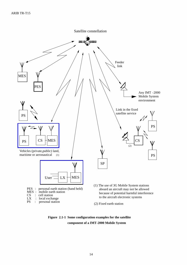
Service configuration of two-way voice or non-voice services provided by IMT-2000 Mobile Satellite System are below: - service directly to/from a mobile earth station (MES); - service directly to/from a personal earth station (PES). The PES would comprise equipment and protocols fully or
partially compatible with the terrestrial-based IMT-2000 Mobile System personal station; - service to/from users connected by a local exchange (LX) via an MES; - service directly to/from a personal station (PS) communicating via an MES. In the case of vehicles with multiple
users a cell station (CS) (cell site for PSs) may be included in the vehicle between the PSs and MES.
Figure 2.1-1 shows some examples for satellite operation involved with a IMT-2000 Mobile System; (ARIB Vol.1 Sec.8/ITU-R M.818-1, Recommends 1)
ARIB TR-T15
14
MES
Figure 2.1-1 Some configuration examples for the satellite
component of a IMT-2000 Mobile System
Feeder link
PES
PS
SP
Link in the fixed satellite service
Satellite constellation
Vehicles (private,public) land, maritime or aeronautical (1)
PES : personal earth station (hand held) MES : mobile earth station CS : cell station LX : local exchange PS : personal station
PS
PS
LX MES User
(2) CS
(1) The use of 3G Mobile System stations aboard an aircraft may not be allowed because of potential harmful interference to the aircraft electronic systems
(2) Fixed earth station
Any IMT - 2000 Mobile System environment
CS MES PS
ARIB TR-T15
15
2.2 Service Requirements
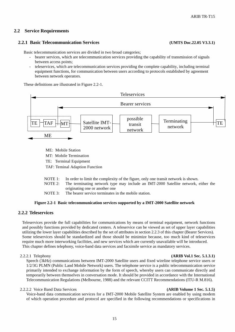
2.2.1 Basic Telecommunication Services (UMTS Doc.22.05 V3.3.1) Basic telecommunication services are divided in two broad categories;
- bearer services, which are telecommunication services providing the capability of transmission of signals between access points;
- teleservices, which are telecommunication services providing the complete capability, including terminal equipment functions, for communication between users according to protocols established by agreement between network operators.
These definitions are illustrated in Figure 2.2-1.
TE MT Satellite IMT-2000 network
possibletransit
network
Terminatingnetwork
Bearer services
Teleservices
ME
ME: Mobile StationMT: Mobile TerminationTE: Terminal EquipmentTAF: Teminal Adaption Function
TETAF
NOTE 1: In order to limit the complexity of the figure, only one transit network is shown. NOTE 2: The terminating network type may include an IMT-2000 Satellite network, either the
originating one or another one NOTE 3: The bearer service terminates in the mobile station.
Figure 2.2-1 Basic telecommunication services supported by a IMT-2000 Satellite network
2.2.2 Teleservices
Teleservices provide the full capabilities for communications by means of terminal equipment, network functions and possibly functions provided by dedicated centers. A teleservice can be viewed as set of upper layer capabilities utilizing the lower layer capabilities described by the set of attributes in section 2.2.3 of this chapter (Bearer Services). Some teleservices should be standardized and those should be minimize because, too much kind of teleservices require much more interworking facilities, and new services which are currently unavailable will be introduced. This chapter defines telephony, voice-band data services and facsimile service as mandatory services.
2.2.2.1 Telephony (ARIB Vol.1 Sec. 5.1.3.1)
Speech (3kHz) communications between IMT-2000 Satellite users and fixed wireline telephone service users or 1/2/3G PLMN (Public Land Mobile Network) users. The telephone service is a public telecommunication service primarily intended to exchange information by the form of speech, whereby users can communicate directly and temporarily between themselves in conversation mode. It should be provided in accordance with the International Telecommunication Regulations (Melbourne, 1988) and the relevant CCITT Recommendations (ITU-R M.816).
2.2.2.2 Voice Band Data Services (ARIB Volume 1 Sec. 5.1.5)
Voice-band data communication services for a IMT-2000 Mobile Satellite System are enabled by using modem of which operation procedure and protocol are specified in the following recommendations or specifications in
ARIB TR-T15
16
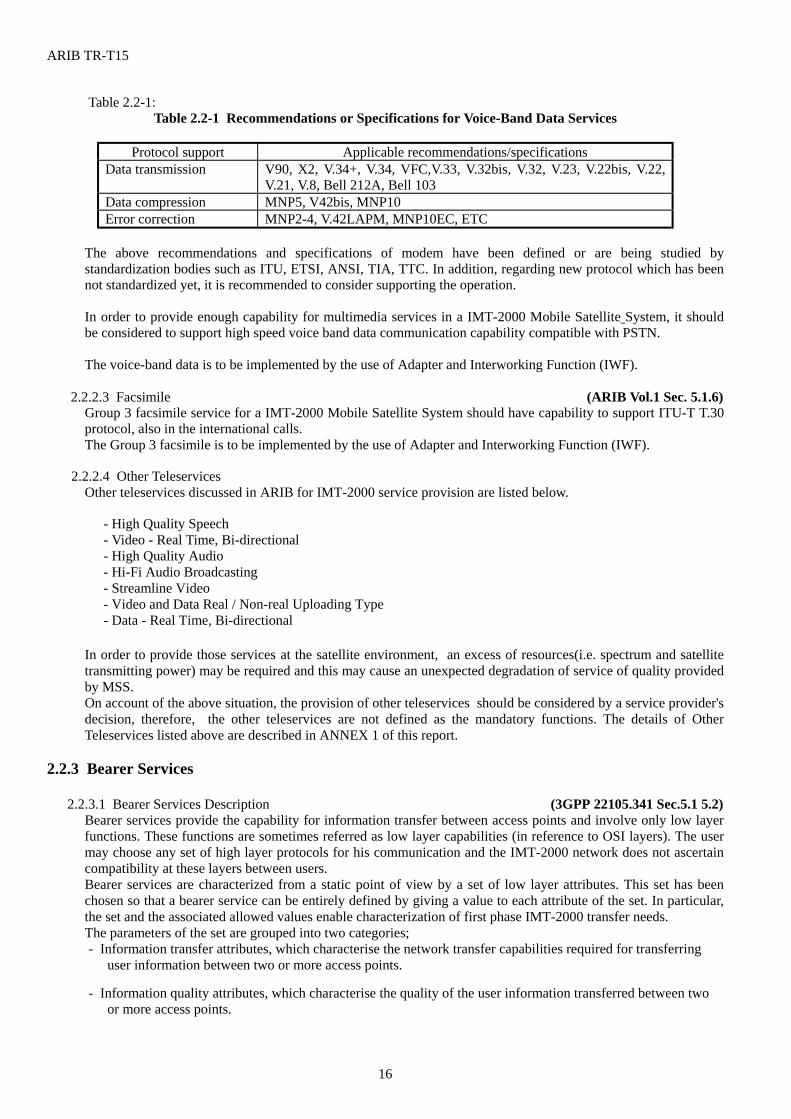
Table 2.2-1: Table 2.2-1 Recommendations or Specifications for Voice-Band Data Services
Protocol support Applicable recommendations/specifications
Data transmission V90, X2, V.34+, V.34, VFC,V.33, V.32bis, V.32, V.23, V.22bis, V.22, V.21, V.8, Bell 212A, Bell 103
Data compression MNP5, V42bis, MNP10 Error correction MNP2-4, V.42LAPM, MNP10EC, ETC
The above recommendations and specifications of modem have been defined or are being studied by standardization bodies such as ITU, ETSI, ANSI, TIA, TTC. In addition, regarding new protocol which has been not standardized yet, it is recommended to consider supporting the operation.
In order to provide enough capability for multimedia services in a IMT-2000 Mobile Satellite System, it should be considered to support high speed voice band data communication capability compatible with PSTN. The voice-band data is to be implemented by the use of Adapter and Interworking Function (IWF).
2.2.2.3 Facsimile (ARIB Vol.1 Sec. 5.1.6)
Group 3 facsimile service for a IMT-2000 Mobile Satellite System should have capability to support ITU-T T.30 protocol, also in the international calls. The Group 3 facsimile is to be implemented by the use of Adapter and Interworking Function (IWF).
2.2.2.4 Other Teleservices
Other teleservices discussed in ARIB for IMT-2000 service provision are listed below. - High Quality Speech - Video - Real Time, Bi-directional - High Quality Audio - Hi-Fi Audio Broadcasting - Streamline Video - Video and Data Real / Non-real Uploading Type - Data - Real Time, Bi-directional
In order to provide those services at the satellite environment, an excess of resources(i.e. spectrum and satellite transmitting power) may be required and this may cause an unexpected degradation of service of quality provided by MSS. On account of the above situation, the provision of other teleservices should be considered by a service provider's decision, therefore, the other teleservices are not defined as the mandatory functions. The details of Other Teleservices listed above are described in ANNEX 1 of this report.
2.2.3 Bearer Services
2.2.3.1 Bearer Services Description (3GPP 22105.341 Sec.5.1 5.2)
Bearer services provide the capability for information transfer between access points and involve only low layer functions. These functions are sometimes referred as low layer capabilities (in reference to OSI layers). The user may choose any set of high layer protocols for his communication and the IMT-2000 network does not ascertain compatibility at these layers between users. Bearer services are characterized from a static point of view by a set of low layer attributes. This set has been chosen so that a bearer service can be entirely defined by giving a value to each attribute of the set. In particular, the set and the associated allowed values enable characterization of first phase IMT-2000 transfer needs. The parameters of the set are grouped into two categories; - Information transfer attributes, which characterise the network transfer capabilities required for transferring
user information between two or more access points.
- Information quality attributes, which characterise the quality of the user information transferred between two or more access points.
ARIB TR-T15
17
Most of the attributes presented further down may be attributed several values when the bearer service required by an application involves more than one traffic type (connection/connectionless) or more than one connection. It shall be possible to negotiate/re-negotiate all of the attributes presented in this clause at call set-up/ during the call (mobile or network initiated).
2.2.3.1.1 Information transfer attributes (3GPP 22105.341 Sec. 5.2.1)
Connection mode attribute The two possible values for this attribute are connection oriented and connectionless. In a connection oriented mode, information is delivered to the destination entity in the same order as it was provided by the source entity, but an establishment/release phase is required at the beginning and the end of the information transfer. In a connectionless mode, information can directly be transferred, but with no guaranty of ordered delivery.
Traffic type attribute The four possible values for this attribute are constant bit rate, variable bit rate, available bit rate and unspecified bit rate.
Symmetry attribute The three possible values for this attribute are unidirectional, bi-directional symmetric and bi-directional asymmetric.
Communication configuration attribute This attribute indicates the spatial arrangement for transferring information between the implicated access points. The possible values are point-to-point, and point-to-multipoint. When the value of the attribute is point-to-multipoint, it shall be further characterized as multicast or broadcast. The addresses of the source entity and the destination entities should also be provided. One multipoint address should be reserved for broadcasting.
Information transfer rate attributes Information transfer rate is the amount of information transmitted per unit of time from a source access point to destination access point(s). The three attributes used to characterize the information transfer rate are the peak bit rate, the minimum bit rate and the mean bit rate. . The possible values for these three attributes are not a limited set, but a continuous range of values. More parameters may certainly be needed, such as the sustainable bit rate or the occupancy (FFS).
2.2.3.1.2 Information quality attributes (3GPP 22105.341 Sec. 5.2.2) Information quality attributes characterize the bit integrity and delay requirements of the applications. Other parameters may be needed.
Maximum transfer delay attribute This attribute sets the maximum transfer delay of the information. The two reference points for the maximum transfer delay are the Iu interface and the point located between the mobile termination and the terminal adaptation function. The possible values for this attribute are not a limited set, but a continuous range of values.
Delay variation attribute This attribute sets the variation in the received information. This attribute is important for real-time services, e.g. video conference, where a value approaching 0 would typically be requested. The possible values for this attribute are not a limited set, but a continuous range of values.
Bit error ratio attribute The ratio between incorrect and total transferred information bits. The possible values for this attribute are not a limited set, but a continuous range of values.
Error characteristics attribute This attribute characterizes the arrivals of errors. The two possible values are uniform and bursty
2.2.3.2 Supported bit rates (3GPP 22105.341 Sec. 5.2.3)
It shall be possible for one application to specify its traffic requirements to the network by requesting a bearer service with any value for the connection mode, traffic type, symmetry and information transfer rate attributes. It shall be possible for the network to satisfy these requirements without wasting resources on the radio and network interfaces due to granularity limitations in bit rates. It shall be possible for one mobile termination to have several active bearer services simultaneously, each of which could be connection oriented or connectionless.
ARIB TR-T15
18
The only limiting factor for satisfying application requirements shall be the cumulative bit rate per mobile termination at a given instant (i.e. when summing the bit rates of one mobile termination’s simultaneous connection oriented and connectionless traffic, irrespective of the traffic being real time or non real time) in each radio environment : At least 32 kbit/s for circuit switched and 32 kbit/s for packet switched for Outdoor, Vehicular and Fixed Environments. At least 9.6 kbit/s for circuit exchange and 9.6 kbit/s for Pedestrian (hand held) Environments. More than 64 kbit/s for later phase services. NOTE 1 : This Peak Bit Rate may only be achieved in a normal operating mode.
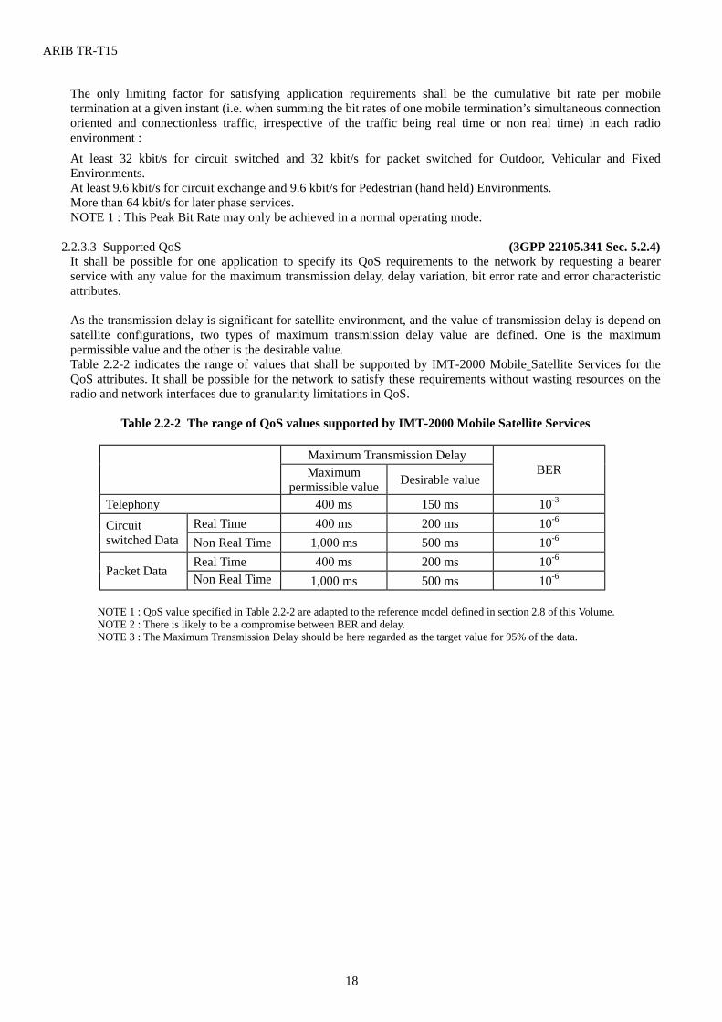
2.2.3.3 Supported QoS (3GPP 22105.341 Sec. 5.2.4) It shall be possible for one application to specify its QoS requirements to the network by requesting a bearer service with any value for the maximum transmission delay, delay variation, bit error rate and error characteristic attributes. As the transmission delay is significant for satellite environment, and the value of transmission delay is depend on satellite configurations, two types of maximum transmission delay value are defined. One is the maximum permissible value and the other is the desirable value. Table 2.2-2 indicates the range of values that shall be supported by IMT-2000 Mobile Satellite Services for the QoS attributes. It shall be possible for the network to satisfy these requirements without wasting resources on the radio and network interfaces due to granularity limitations in QoS.
Table 2.2-2 The range of QoS values supported by IMT-2000 Mobile Satellite Services
Maximum Transmission Delay Maximum
permissible value Desirable value BER
Telephony 400 ms 150 ms 10-3 Real Time 400 ms 200 ms 10-6 Circuit
switched Data Non Real Time 1,000 ms 500 ms 10-6 Real Time 400 ms 200 ms 10-6
Packet Data Non Real Time 1,000 ms 500 ms 10-6
NOTE 1 : QoS value specified in Table 2.2-2 are adapted to the reference model defined in section 2.8 of this Volume. NOTE 2 : There is likely to be a compromise between BER and delay. NOTE 3 : The Maximum Transmission Delay should be here regarded as the target value for 95% of the data.
ARIB TR-T15
19
2.2.3.4 Supported topologies (3GPP 22105.341 Sec. 5.2.5) It shall be possible for an application to specify its traffic topology requirements to the network by requesting a bearer service with any value for the communication configuration attribute. However, some combinations with the symmetry attribute are not authorized. The supported configurations are: 1) Point-to-Point
- Uni-Directional - Bi-Directional - Symmetric - Asymmetric
2) Uni-Directional Point-to-Multipoint - Multicast - Broadcast
A multicast topology is one in which sink parties are specified before the connection is established, or by subsequent operations to add or remove parties from the connection. The source of the connection will always be aware of all parties to which the connection travels. A broadcast topology is one in which the sink parties are not always known to the source. The connection to individual sink parties is not under the control of the source, but is by request of each sink party. In the case of a mobile termination with several active bearer services simultaneously, it shall be possible for each bearer service to have independent topologies and source/sink parties.
2.2.3.5 Radio Interface optimization (3GPP 22105.341 Sec. 5.2.6)
The following requirements shall lead the radio interface optimization process; - support of high bit rate (around the Peak Bit Rate), bursty, asymmetric, non-real time bearer capabilities; - support of high bit rate (around the Peak Bit Rate), bursty, asymmetric, real time bearer capabilities; - the ability to extend or reduce bandwidth associated to a bearer capability in order to adapt to bit rate or radio
condition variations, to add or drop service components. In order to allow the support of flexible, bandwidth on demand services, bearer services should be provided with the finest possible granularity that can be efficiently supported.
2.2.4 Supplementary Services (ARIB Vol.1 Sec. 5.1.7) Supplementary services supported in the pre-IMT-2000 mobile systems should be supported in a IMT-2000 mobile system, as far as possible. The possible supplementary services include the input from ISDN, PDC, IS-53, GSM and the requirements for FWA, are listed in Annex 5 of ARIB Volume 1 ; Requirements and Objectives for 3G Mobile Services and System. Supplementary services listed in Annex 5 of ARIB Volume 1 ; Requirements and Objectives for 3G Mobile Services and System are summarized as following categories.
(1) Number Identification Supplementary Services (2) Call Offering Supplementary Services (3) Call Completion Supplementary Services (4) Multiparty Supplementary Services (5) Community of Interest Supplementary Services (6) Charging Supplementary Services (7) Additional Information Transfer Supplementary Services (8) Origination and Termination Restriction Supplementary Services (9) Priority Services (10) Security and Privacy Services (11) Feature Control and Interrogation Services (12) Smart Dialing Services (13) Mobile Bearer Specific Services (14) Operator Supplementary Services (15) Multiple Subscriber Profile
ARIB TR-T15
20
2.2.5 Mobile Specific Service
The Location Service is the basic Mobile Specific service for IMT-2000. However, for satellite mobile telecommunication services whether IMT-2000 or non-IMT-2000, it is difficult to provide the location services without the help of any other positioning facility. ITU-R TG8/1 is now discussing about the implementation of the location determination facility to satellite IMT-2000 terminals. This chapter do not describe about the location facilities, until the discussion of ITU-R comes to conclusion of implementing those facilities to satellite IMT-2000 terminals.
2.2.5.1 High Penetration Message Service (i.e. Paging) (ARIB Vol.1 Sec. 5.1.8.3) An IMT-2000 Mobile Satellite System should be able to provide paging service. The users can send not only a simple alert message (e.g. tone only) or some character message (e.g. numeric, alphanumeric or transparent data) but various information by data, voice, image or video. Occasionally, those information type is multiplexed. Therefore, it is in the wide range of 0.3 kbit/s to 32 kbit/s, depending on the service applications and contents. The required QoS is equivalent to the other data download services. This service is, in some cases, bi-directional communications between individual users via storage units i.e. paging center.
2.2.5.2 Short Message (ARIB Vol.1 Sec. 5.1.8.2)
An IMT-2000 Mobile Satellite System is required to support Short Message Service and these connectionless services allow the exchange of messages of limited length (e.g. a few hundred characters) between a storage system and a mobile station, or between mobile stations via MSS in real time. It can be a point-to-point or point-to-multipoint service.
2.2.5.3 Specific Dispatch Services
Group Call, Broadcast Call, Selective Broadcast Call etc. are listed as Specific Dispatch Services. Those services have somehow advantages for satellite environment, because it can be provided for MSS services to wide area at the same time. However, the provision of those services should be considered by a service provider's decision. Therefore, Specific Dispatch Services are not defined as the mandatory functions. The details of Specific Dispatch Services are described in ANNEX 1 of this report.
2.2.6 IP Based Services (ARIB Vol.1 Sec. 5.1.1.6) An IMT-2000 Mobile Satellite System should support IP (Internet Protocol) based services. The Internet Protocol is specifically limited in scope to provide the functions necessary to deliver a package of bits from a source to a destination over an interconnected system of networks. A IMT-2000 Mobile Satellite System should support those delivery of IP packet data. The Internet Protocol can capitalize on the services of its supporting networks to provide various types and qualities of service. The IP-based services provide a number of multimedia and data applications to users via the Internet. It will be one of the major and basic services to be supported in a IMT-2000 Mobile Satellite System. Examples of applications are shown below:
- WWW - E-mail - FTP - Telnet - Chat
TCP or UDP will be applied as the transport protocol for the service. The required user bit rate depends on applications and contents. Therefore, it is in the wide range from voice band data modem bit rates to 64 k bit/s. Because Internet service is conventionally best effort one, the end-to-end delay is not critical but it is necessary to reduce command response time in order to realize comfortable user environment.
2.2.7 Services to be considered for Later Phase (ARIB Vol.1 Sec. 5.5) 2.2.7.1 Service Requirements for IMT-2000 Mobile Satellite System Phase 1
The Phase 1 standardization of a IMT-2000 Mobile Satellite System is targeted based on a two-step approach. Step 1 is defined as a set of bearer channel capabilities which include the circuit transfer mode bearer channels at
ARIB TR-T15
21
up to 38.4 kbit/s and packet transfer mode bearer channel at 64 kbit/s for pedestrian environments and vehicular environments. For Terrestrial IMT-2000 Mobile Systems, standardization of Step 1 capabilities will be finalized at the first half of 1999 in order for these capabilities to be available for services in 2001. On the other hand, IMT-2000 Mobile Satellite System Phase 1 will be started delayed for several years from that of the Terrestrial IMT-2000 Mobile Systems.
Step 2 is defined as a set of bearer channel capabilities which include the circuit transfer mode bearer channel at up to approximately 144 kbit/s and the packet transfer mode bearer channel at 384 kbit/s for pedestrian environments and vehicular environments. For Terrestrial IMT-2000 Mobile Systems, standardization of Step 2 capabilities will be targeted for 2002, provided that high level definitions such as the system architecture and major parameters will be available when the details of Step 1 capabilities are defined. Step 2 of IMT-2000 Mobile Satellite System will be started further delayed for several years from the start of Step 1. It will be required for realizing Step 2 of IMT-2000 Mobile Satellite System to develop new technologies not only for communication technologies but also for satellite related technologies including constellation control technique and onboard equipment.
A IMT-2000 Mobile Satellite System shall be capable of supporting pre IMT-2000 Satellite services currently available in a manner transparent to the users of pre IMT-2000 Satellite services. In addition to these services, a IMT-2000 Mobile Satellite System should offer such services that can differentiate itself from the pre IMT-2000 Satellite services. Based on these considerations, the details of the following services shall be standardized coordinating with terrestrial IMT-2000 services:
- Telephony - Voice-Band Data Service - Group 3 Facsimile Service - Supplementary Service (at least being supported by the existing 2G system) - Location Services - Short Message Service - Paging Service - Internet Access Services(IP based services)
It should be noted that the following service features shall be available to any of the services listed above: - Security and Privacy - User Mobility - Charging
Other services listed below will also be able to be implemented using the Step 1 bearer capabilities. It is desirable that these services are standardized in the time frame of Step 1 standardization.
- High Quality Audio - Hi-Fi Audio Broadcasting - Streamline Video - Video and Data Real / Non-real Uploading Type - Data - Real Time, Bi-directional - Specific Dispatch Services
It should be noted that the services listed above could be augmented by the availability of the Step 2 capabilities.
2.2.7.2 Services to be considered for later phases (ARIB Vol.1 Sec. 5.6) It is important to incorporate emerging and new services requirements in the IMT-2000 Mobile System service portfolio as time goes by. For the terrestrial environment, one of the service areas that can be augmented in the later phases will be those that uses higher bit rate bearer capabilities becoming available in the wider range of operating environments. For the satellite environment, on the other hand, some of the new services may be provided by phase 1 satellite systems, however new other services may require newly developed satellite system. Examples of such services are listed below:
- support of the high data rate needs of portable computing users, and - support of enhanced multimedia communications requirements
ARIB TR-T15
22
2.3 Access Requirement (ARIB Vol.1 Sec.5.1.1.3/M.816, sec.4.5) For access to the fixed networks : a IMT-2000 Mobile Satellite System may be either an adjunct to or an integral part of the PSTN/ISDN. Services offered in the PSTN/ISDN should, as far as possible, be offered to IMT-2000 Mobile Satellite System users;
- for international operation : a IMT-2000 Mobile Satellite System should allow international operation and automatic roaming of mobile users and stations to the extent practical or permitted;
- for maritime and aeronautical : a IMT-2000 Mobile Satellite System should allow operation in the maritime and aeronautical environment to the extent permitted by national and international regulatory authorities;
- for terrestrial system : a IMT-2000 Mobile Satellite System should allow operation with terrestrial Mobile System.
For access to the other PLMN : a IMT-2000 Mobile Satellite System should have a interworking function, if needed;
- for inter-system operation : A IMT-2000 Mobile Satellite System should consider the ability to support multi-mode operation service between inter-systems including different generation system, i.e. a pre-IMT-2000 and a IMT-2000 Mobile System.
- for other satellite system : For a mobile satellite system which has its own universal coverage, ability to support multi-mode operation with other Satellite Mobile System is not necessarily required.
For access to Internet : a IMT-2000 Mobile Satellite System should have the ability to support internet protocol, addressing etc..
ARIB TR-T15
23
2.4 User Mobility 2.4.1 Terminal Mobility The terminal mobility provides the users with the ability to be in continuous motion whilst accessing and using telecommunication services and the network with the capability to keep track of the moving user terminal. Because of very wide coverage of IMT2000 Satellite Mobile Systems, Satellite Mobile Systems are capable of practicing the terminal mobility over the wide range of service area up to all over the world. This requires the telecommunication services to be available throughout the Satellite Mobile System coverage and ideally at all times. 2.4.2 User Mobility The user mobility is conferred by the flexibility of access by users to telecommunication services which are available at any terminal, in such a way that the user gives its identity and related profiles by means of detachable UIM to the mobile terminal and/or Satellite Mobile System to be accessed, and may configure any one of these terminals, fixes or mobile, to meet its service requirements. The user mobility involves the Satellite Mobile System capability to locate a user with reference to a unique user identity (i.e. IMT-2000 number) for the purpose of addressing, routing and charging of calls. 2.5 Roaming and Handover (ITU-R M.1034, Sec.11.2.2) 2.5.1 Roaming 2.5.1.1 Support between IMT-2000 Terrestrial System (ITU-R M.1034, Sec.11.2.2.1) Service coverage of IMT2000 Mobile Satellite Systems is intrinsically very wide, and especially non-GSO Mobile Satellite Systems would provide global telecommunication services, for that reason, the roaming between Mobile Satellite Systems is not necessary. On the other hand the standardized IMT-2000 Mobile Satellite System radio interfaces shall have the capability to support roaming facilities between IMT-2000 terrestrial Mobile System operators. The support of this feature in 3G Mobile Satellite System will depend on the service capabilities of the 3G Mobile Satellite System, which are up to System manufacturers, and on administrative inter-operator agreements on the Terrestrial Mobile System side, which may also imply subscription restrictions. In order to be able to adapt to changes of operational environments and to provide technical roaming capabilities between 3G terrestrial Mobile System radio operating environments and between different types of 3G terrestrial Mobile System operators, the 3G Mobile Satellite System radio interface(s) shall have the capability to identify terrestrial networks and their structure, and for the 3G Mobile Satellite System mobile terminals to detect and understand this scenario. 2.5.1.2 Physical Radio Interface Compatibility (ITU-R M.1034, 11.2.2.2) Irrespective of the eventual choice(s) of physical radio interface(s), the design of the physical 3G Mobile Satellite System radio interface(s) shall facilitate roaming capabilities between 3G terrestrial Mobile System radio operating environments. 2.5.2 Handover (ITU-R M.1034, Sec.11.2.3) The services provided to a 3G Mobile Satellite System user shall in principle be unchanged by handover and the qualities of service provided to a 3G Mobile Satellite System user shall in principle be maintained or improved. 2.5.2.1 Support of Handover (ITU-R M.1034, Sec.11.2.3.1) The support of handover capabilities in a 3G Mobile Satellite System should be depend on the operator's selection in most cases with the exception of handover in a same 3G Mobile Satellite System. There are five cases of handover execution. 1) Handover in a same 3G Mobile Satellite System 2) Handover from a 3G Terrestrial Mobile System to a 3G Mobile Satellite System 3) Handover from a 3G Mobile Satellite System to 3G Terrestrial Mobile System
ARIB TR-T15
24
4) Handover from a 3G Mobile Satellite System to another 3G Mobile Satellite System 5) Handover from a 3G Mobile Satellite System to 2G Mobile Satellite/Terrestrial System Handover Capabilities in a same Non-GSO 3G Mobile Satellite System shall be supported. Handover Capabilities should contain not only Handover between Spot beams, but also handover between Satellites and between Base earth Stations Handover Capabilities in a same GSO 3G Mobile Satellite System should be supported for high mobility users such as airplane and/or high speed railway users. A 3G Mobile Satellite System shall be designed to have the capability to support handover from a 3G Terrestrial Mobile System to a 3G Mobile Satellite System. The support of this feature in the 3G terrestrial mobile stations should be depend on the operator's selection and will depend on the service capabilities of the 3G terrestrial mobile station, which are up to mobile station manufacturers, on the network implementation of a service in a geographical area, and on administrative inter-operator agreements, which may also imply subscription restrictions. The support of handover capabilities from a 3G Mobile Satellite System to a 3G Terrestrial Mobile System is not essential for a 3G Mobile Satellite System. The adoption of this capability is beneficial for user because of providing cost-effective services and for operator moderating surplus traffic demands to 3G mobile Satellite systems. To realize this Capability, Mobile Satellite Terminal needs to detect the 3G Terrestrial Mobile system service area, and so the adoption of this handover capability should depend on the operator's selection.
The adoption of handover capabilities from a 3G Mobile Satellite System to another 3G Mobile Satellite System might be necessary for 3G Mobile Satellite GSO System which operate in a specific service area. The adoption of this handover capabilities should be depend on the operator's selection.
Handover from a 3G Mobile Satellite System to a 2G Mobile Satellite/Terrestrial System is not required. 2.5.2.2 Types of Handover (ITU-R M.1034, Sec.11.2.3.3) Handover capabilities in a same 3G Mobile Satellite System should adopt a soft handover scheme. In another cases of handover, handover may adopt a hard handover scheme, but it is desirable to adopt very similar scheme such as a soft handover scheme for user's benefit. The 3G Mobile Satellite System radio interface(s) shall also support multi-bearer hangovers and radio originated as well as network originated handovers, as applicable to the 3G Mobile Satellite System types. 2.5.2.3 Seamless Handover (ITU-R M.1034, Sec.11.2.3.4) In a 3G Mobile Satellite System, the goal is to have an end-to-end quality of service which is comparable to that of the 3G Terrestrial Mobile Systems. The 3G Mobile Satellite System radio interface(s) shall be designed to the greatest extent practicable such that the execution of handover is unnoticeable to the end users (seamless handover),. Every effort shall be made to accommodate this requirement of maintaining the quality of service during handover, including the possible momentary use of more than one radio channel. However, the design of the handover procedures over the 3G Mobile Satellite System radio interface(s) shall be such that execution of handover does not significantly decrease the system capacity. 2.5.2.4 Signalling Load of Handover (ITU-R M.1034, Sec.11.2.3.5) The 3G Mobile Satellite System radio interface(s) shall be designed such that the signalling procedure required to execute handover is as short (quick) as possible. This is necessary in order to accommodate high speed moving Spot beams, or to accommodate high-speed moving mobile satellite terminals at spot beam boundaries. The 3G Mobile System radio interface(s) shall be designed such that the signalling load of handover shall be kept to a minimum.
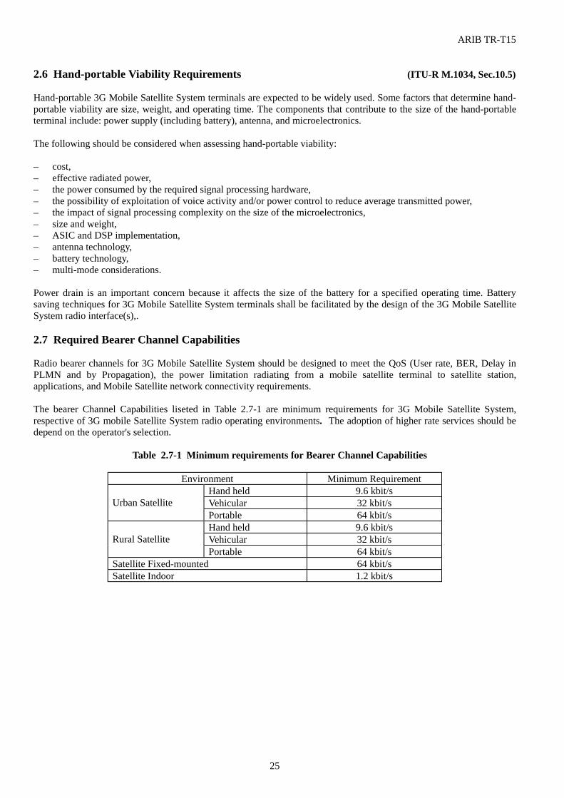
ARIB TR-T15
25
2.6 Hand-portable Viability Requirements (ITU-R M.1034, Sec.10.5) Hand-portable 3G Mobile Satellite System terminals are expected to be widely used. Some factors that determine hand-portable viability are size, weight, and operating time. The components that contribute to the size of the hand-portable terminal include: power supply (including battery), antenna, and microelectronics. The following should be considered when assessing hand-portable viability: – cost, – effective radiated power, – the power consumed by the required signal processing hardware, – the possibility of exploitation of voice activity and/or power control to reduce average transmitted power, – the impact of signal processing complexity on the size of the microelectronics, – size and weight, – ASIC and DSP implementation, – antenna technology, – battery technology, – multi-mode considerations. Power drain is an important concern because it affects the size of the battery for a specified operating time. Battery saving techniques for 3G Mobile Satellite System terminals shall be facilitated by the design of the 3G Mobile Satellite System radio interface(s),. 2.7 Required Bearer Channel Capabilities Radio bearer channels for 3G Mobile Satellite System should be designed to meet the QoS (User rate, BER, Delay in PLMN and by Propagation), the power limitation radiating from a mobile satellite terminal to satellite station, applications, and Mobile Satellite network connectivity requirements.
The bearer Channel Capabilities liseted in Table 2.7-1 are minimum requirements for 3G Mobile Satellite System, respective of 3G mobile Satellite System radio operating environments. The adoption of higher rate services should be depend on the operator's selection.
Table 2.7-1 Minimum requirements for Bearer Channel Capabilities
Environment Minimum Requirement Hand held 9.6 kbit/s Vehicular 32 kbit/s Urban Satellite Portable 64 kbit/s Hand held 9.6 kbit/s Vehicular 32 kbit/s Rural Satellite Portable 64 kbit/s
Satellite Fixed-mounted 64 kbit/s Satellite Indoor 1.2 kbit/s
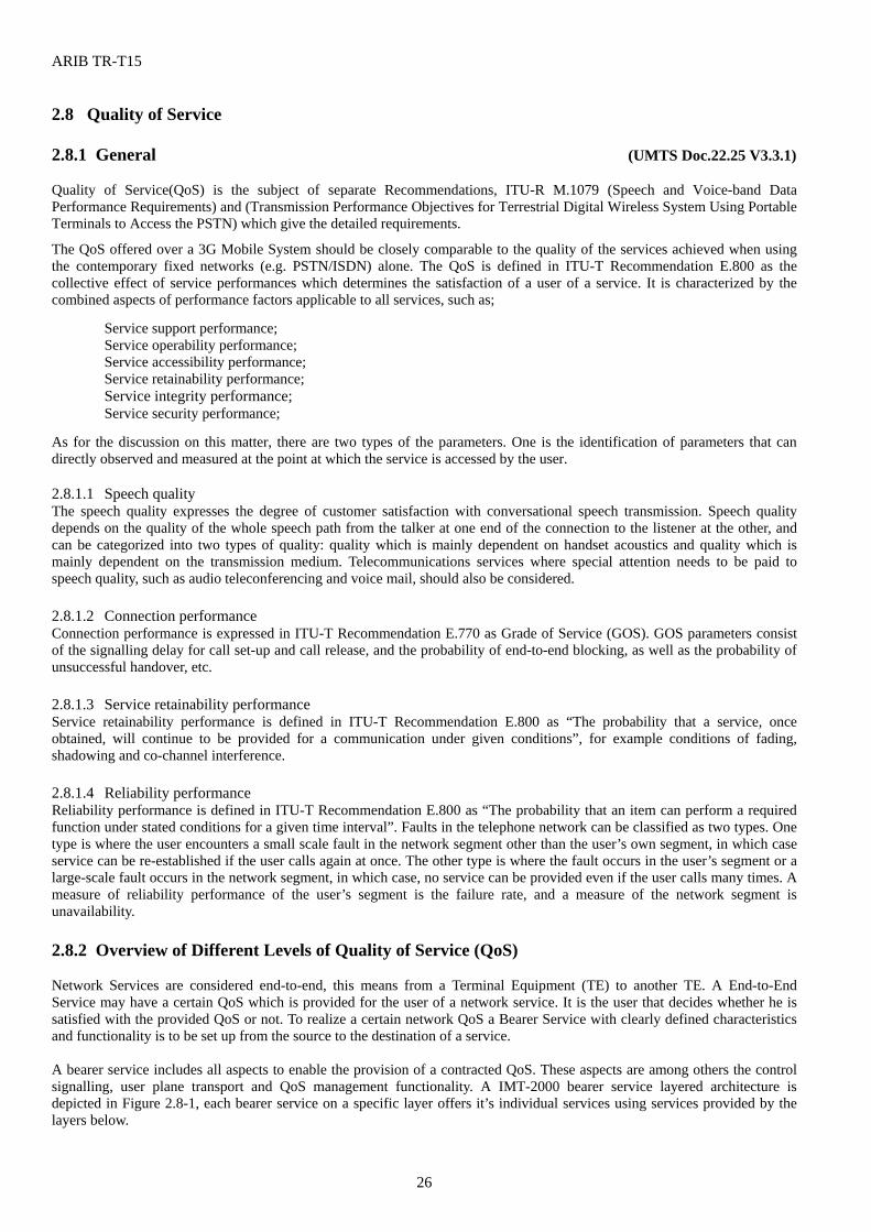
ARIB TR-T15
26
2.8 Quality of Service 2.8.1 General (UMTS Doc.22.25 V3.3.1) Quality of Service(QoS) is the subject of separate Recommendations, ITU-R M.1079 (Speech and Voice-band Data Performance Requirements) and (Transmission Performance Objectives for Terrestrial Digital Wireless System Using Portable Terminals to Access the PSTN) which give the detailed requirements.
The QoS offered over a 3G Mobile System should be closely comparable to the quality of the services achieved when using the contemporary fixed networks (e.g. PSTN/ISDN) alone. The QoS is defined in ITU-T Recommendation E.800 as the collective effect of service performances which determines the satisfaction of a user of a service. It is characterized by the combined aspects of performance factors applicable to all services, such as; Service support performance; Service operability performance; Service accessibility performance; Service retainability performance; Service integrity performance; Service security performance; As for the discussion on this matter, there are two types of the parameters. One is the identification of parameters that can directly observed and measured at the point at which the service is accessed by the user. 2.8.1.1 Speech quality The speech quality expresses the degree of customer satisfaction with conversational speech transmission. Speech quality depends on the quality of the whole speech path from the talker at one end of the connection to the listener at the other, and can be categorized into two types of quality: quality which is mainly dependent on handset acoustics and quality which is mainly dependent on the transmission medium. Telecommunications services where special attention needs to be paid to speech quality, such as audio teleconferencing and voice mail, should also be considered. 2.8.1.2 Connection performance Connection performance is expressed in ITU-T Recommendation E.770 as Grade of Service (GOS). GOS parameters consist of the signalling delay for call set-up and call release, and the probability of end-to-end blocking, as well as the probability of unsuccessful handover, etc. 2.8.1.3 Service retainability performance Service retainability performance is defined in ITU-T Recommendation E.800 as “The probability that a service, once obtained, will continue to be provided for a communication under given conditions”, for example conditions of fading, shadowing and co-channel interference. 2.8.1.4 Reliability performance Reliability performance is defined in ITU-T Recommendation E.800 as “The probability that an item can perform a required function under stated conditions for a given time interval”. Faults in the telephone network can be classified as two types. One type is where the user encounters a small scale fault in the network segment other than the user’s own segment, in which case service can be re-established if the user calls again at once. The other type is where the fault occurs in the user’s segment or a large-scale fault occurs in the network segment, in which case, no service can be provided even if the user calls many times. A measure of reliability performance of the user’s segment is the failure rate, and a measure of the network segment is unavailability. 2.8.2 Overview of Different Levels of Quality of Service (QoS) Network Services are considered end-to-end, this means from a Terminal Equipment (TE) to another TE. A End-to-End Service may have a certain QoS which is provided for the user of a network service. It is the user that decides whether he is satisfied with the provided QoS or not. To realize a certain network QoS a Bearer Service with clearly defined characteristics and functionality is to be set up from the source to the destination of a service. A bearer service includes all aspects to enable the provision of a contracted QoS. These aspects are among others the control signalling, user plane transport and QoS management functionality. A IMT-2000 bearer service layered architecture is depicted in Figure 2.8-1, each bearer service on a specific layer offers it’s individual services using services provided by the layers below.
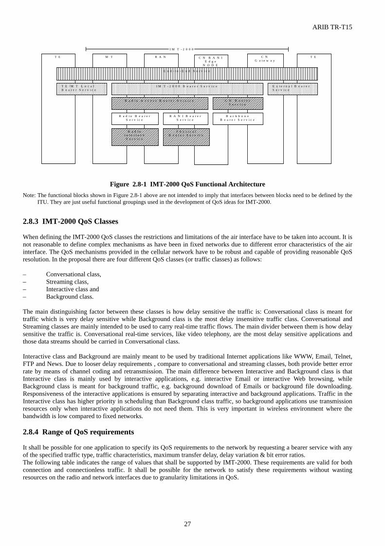
ARIB TR-T15
27
T E M T R A N C N R A N IE d g e
N O D E
C NG a t e w a y
T E
I M T - 2 0 0 0
��������������������������������������������������������������������������������������������������������������������������������������������������������������������������������������������������������������������������������������������������������������������������������������������������������������������������������������������������������������������������������������������������������������������������������������E n d - t o - E n d S e r v i c e
����������������������������������������������������������������������������������T E / M T L o c a l
B e a r e r S e r v i c eU M T S B e a r e r S e r v i c e
����������������������������������������������������������������������������������E x t e r n a l B e a r e r
S e r v i c e
������������������������������������������������������������������������������������������������������������������������������������������������������������������������������������������������������������������������������������������������������I M T - 2 0 0 0 B e a r e r S e r v i c e
��������������������������������������������������������������������������������������������������������������������������������������������������������������R a d i o A c c e s s B e a r e r S e r v i c e
����������������������������������������������������������������������������������C N B e a r e r
S e r v i c e
B a c k b o n eB e a r e r S e r v i c e
R A N I B e a r e rS e r v i c e
R a d i o B e a r e rS e r v i c e
���������������������������������������������������������������������������������������������������������������������
R a d i oI n t e r f a c e
S e r v i c e
������������������������������������������������������������������������������������������������������������������
P h y s i c a lB e a r e r S e r v i c e
Figure 2.8-1 IMT-2000 QoS Functional Architecture
Note: The functional blocks shown in Figure 2.8-1 above are not intended to imply that interfaces between blocks need to be defined by the ITU. They are just useful functional groupings used in the development of QoS ideas for IMT-2000.
2.8.3 IMT-2000 QoS Classes When defining the IMT-2000 QoS classes the restrictions and limitations of the air interface have to be taken into account. It is not reasonable to define complex mechanisms as have been in fixed networks due to different error characteristics of the air interface. The QoS mechanisms provided in the cellular network have to be robust and capable of providing reasonable QoS resolution. In the proposal there are four different QoS classes (or traffic classes) as follows: – Conversational class, – Streaming class, – Interactive class and – Background class. The main distinguishing factor between these classes is how delay sensitive the traffic is: Conversational class is meant for traffic which is very delay sensitive while Background class is the most delay insensitive traffic class. Conversational and Streaming classes are mainly intended to be used to carry real-time traffic flows. The main divider between them is how delay sensitive the traffic is. Conversational real-time services, like video telephony, are the most delay sensitive applications and those data streams should be carried in Conversational class. Interactive class and Background are mainly meant to be used by traditional Internet applications like WWW, Email, Telnet, FTP and News. Due to looser delay requirements , compare to conversational and streaming classes, both provide better error rate by means of channel coding and retransmission. The main difference between Interactive and Background class is that Interactive class is mainly used by interactive applications, e.g. interactive Email or interactive Web browsing, while Background class is meant for background traffic, e.g. background download of Emails or background file downloading. Responsiveness of the interactive applications is ensured by separating interactive and background applications. Traffic in the Interactive class has higher priority in scheduling than Background class traffic, so background applications use transmission resources only when interactive applications do not need them. This is very important in wireless environment where the bandwidth is low compared to fixed networks. 2.8.4 Range of QoS requirements It shall be possible for one application to specify its QoS requirements to the network by requesting a bearer service with any of the specified traffic type, traffic characteristics, maximum transfer delay, delay variation & bit error ratios. The following table indicates the range of values that shall be supported by IMT-2000. These requirements are valid for both connection and connectionless traffic. It shall be possible for the network to satisfy these requirements without wasting resources on the radio and network interfaces due to granularity limitations in QoS.
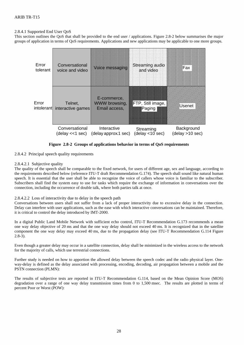
ARIB TR-T15
28
2.8.4.1 Supported End User QoS This section outlines the QoS that shall be provided to the end user / applications. Figure 2.8-2 below summarises the major groups of application in terms of QoS requirements. Applications and new applications may be applicable to one more groups.
Errortolerant
Errorintolerant
Conversational(delay <<1 sec)
Interactive(delay approx.1 sec)
Streaming(delay <10 sec)
Background(delay >10 sec)
Conversationalvoice and video
���������������������������������������������������������������������������������������������������������������������������������������������������������������������������������������������������������������������������������������������������������������������������������������������������������������������������������������������������������������������������������������������������������������������������������������������������������
Voice messaging
������������������������������������������������������������������������������������������������������������������������������������������������������������������������������������������������������������������������������������������������������������������������������������������������������������������������������������������������������������������������������������������������������������������������������������������������������������������
Streaming audioand video
������������������������������������������������������������������������������������������������������������������������������������������������������������������������������������������������������������������������������������������������������������������������������������������������������������������������������������������������������������������������������������������������������������������������������������������������������������������������������������������������������������������������������������������������������������������������������������������������������������������������������������������������������������������������������������������������������������������������������������������������������������������������������������������������������������������������������������������������������������������������������������������������������������������
������������������������������������������������������������������������������������������������������������������������������������������������������������������������������������������������������������������������������������������������������������������������������������������������������������������������������������������������������������������������������������������������������������������������������������������������������������������
UsenetPagingFTP, Still image,
E-commerce,WWW browsing,
Email access,Telnet,
interactive games
Fax
Figure 2.8-2 Groups of applications behavior in terms of QoS requirements
2.8.4.2 Principal speech quality requirements 2.8.4.2.1 Subjective quality The quality of the speech shall be comparable to the fixed network, for users of different age, sex and language, according to the requirements described below (reference ITU-T draft Recommendation G.174). The speech shall sound like natural human speech. It is essential that the user shall be able to recognize the voice of callers whose voice is familiar to the subscriber. Subscribers shall find the system easy to use for tasks which require the exchange of information in conversations over the connection, including the occurrence of double talk, where both parties talk at once. 2.8.4.2.2 Loss of interactivity due to delay in the speech path Conversations between users shall not suffer from a lack of proper interactivity due to excessive delay in the connection. Delay can interfere with user applications, such as the ease with which interactive conversations can be maintained. Therefore, it is critical to control the delay introduced by IMT-2000. In a digital Public Land Mobile Network with sufficient echo control, ITU-T Recommendation G.173 recommends a mean one way delay objective of 20 ms and that the one way delay should not exceed 40 ms. It is recognized that in the satellite component the one way delay may exceed 40 ms, due to the propagation delay (see ITU-T Recommendation G.114 Figure 2.8-3). Even though a greater delay may occur in a satellite connection, delay shall be minimized in the wireless access to the network for the majority of calls, which use terrestrial connections. Further study is needed on how to apportion the allowed delay between the speech codec and the radio physical layer. One-way-delay is defined as the delay associated with processing, encoding, decoding, air propagation between a mobile and the PSTN connection (PLMN): The results of subjective tests are reported in ITU-T Recommendation G.114, based on the Mean Opinion Score (MOS) degradation over a range of one way delay transmission times from 0 to 1,500 msec. The results are plotted in terms of percent Poor or Worst (POW):
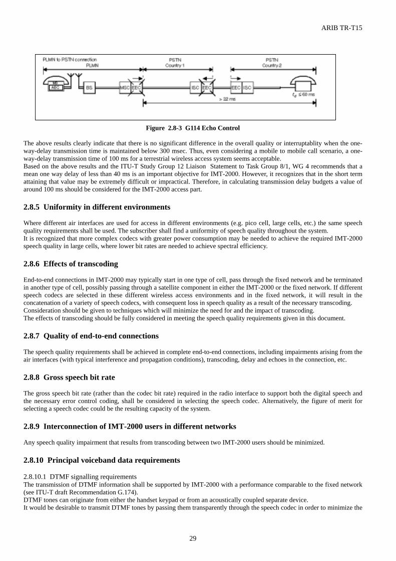
ARIB TR-T15
29
Figure 2.8-3 G114 Echo Control The above results clearly indicate that there is no significant difference in the overall quality or interruptablity when the one-way-delay transmission time is maintained below 300 msec. Thus, even considering a mobile to mobile call scenario, a one-way-delay transmission time of 100 ms for a terrestrial wireless access system seems acceptable. Based on the above results and the ITU-T Study Group 12 Liaison Statement to Task Group 8/1, WG 4 recommends that a mean one way delay of less than 40 ms is an important objective for IMT-2000. However, it recognizes that in the short term attaining that value may be extremely difficult or impractical. Therefore, in calculating transmission delay budgets a value of around 100 ms should be considered for the IMT-2000 access part. 2.8.5 Uniformity in different environments Where different air interfaces are used for access in different environments (e.g. pico cell, large cells, etc.) the same speech quality requirements shall be used. The subscriber shall find a uniformity of speech quality throughout the system. It is recognized that more complex codecs with greater power consumption may be needed to achieve the required IMT-2000 speech quality in large cells, where lower bit rates are needed to achieve spectral efficiency. 2.8.6 Effects of transcoding End-to-end connections in IMT-2000 may typically start in one type of cell, pass through the fixed network and be terminated in another type of cell, possibly passing through a satellite component in either the IMT-2000 or the fixed network. If different speech codecs are selected in these different wireless access environments and in the fixed network, it will result in the concatenation of a variety of speech codecs, with consequent loss in speech quality as a result of the necessary transcoding. Consideration should be given to techniques which will minimize the need for and the impact of transcoding. The effects of transcoding should be fully considered in meeting the speech quality requirements given in this document. 2.8.7 Quality of end-to-end connections The speech quality requirements shall be achieved in complete end-to-end connections, including impairments arising from the air interfaces (with typical interference and propagation conditions), transcoding, delay and echoes in the connection, etc. 2.8.8 Gross speech bit rate The gross speech bit rate (rather than the codec bit rate) required in the radio interface to support both the digital speech and the necessary error control coding, shall be considered in selecting the speech codec. Alternatively, the figure of merit for selecting a speech codec could be the resulting capacity of the system. 2.8.9 Interconnection of IMT-2000 users in different networks Any speech quality impairment that results from transcoding between two IMT-2000 users should be minimized. 2.8.10 Principal voiceband data requirements 2.8.10.1 DTMF signalling requirements The transmission of DTMF information shall be supported by IMT-2000 with a performance comparable to the fixed network (see ITU-T draft Recommendation G.174). DTMF tones can originate from either the handset keypad or from an acoustically coupled separate device. It would be desirable to transmit DTMF tones by passing them transparently through the speech codec in order to minimize the
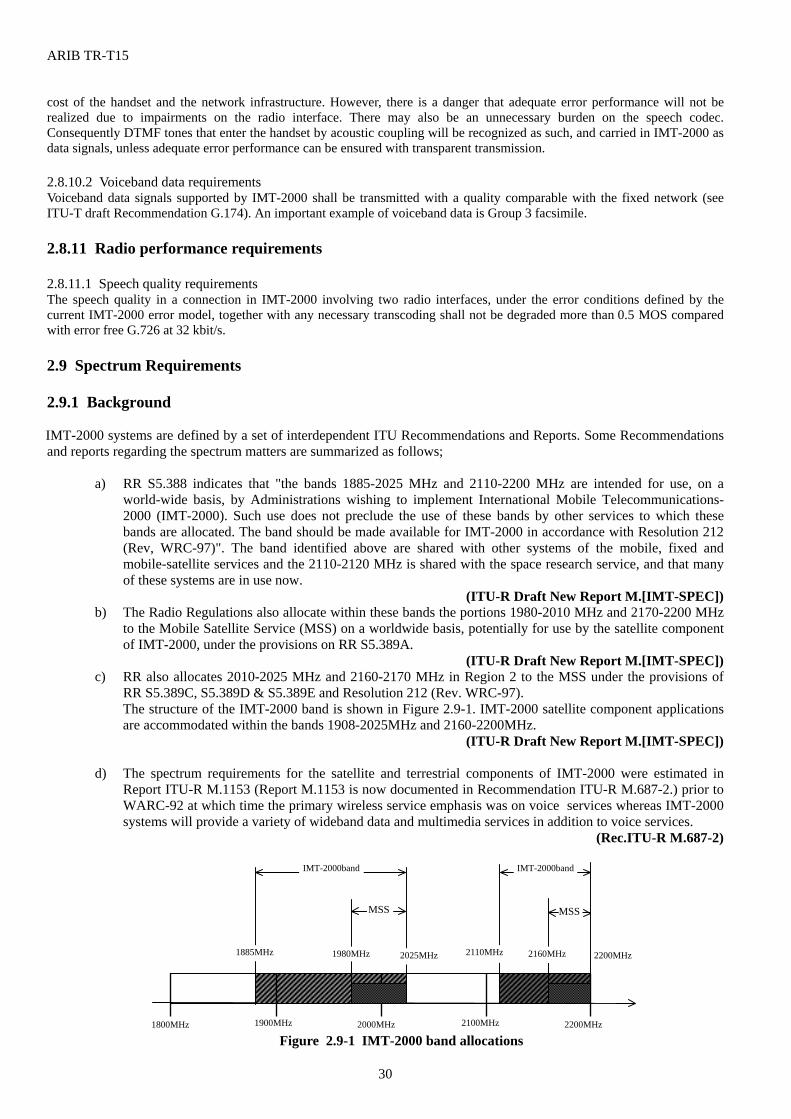
ARIB TR-T15
30
cost of the handset and the network infrastructure. However, there is a danger that adequate error performance will not be realized due to impairments on the radio interface. There may also be an unnecessary burden on the speech codec. Consequently DTMF tones that enter the handset by acoustic coupling will be recognized as such, and carried in IMT-2000 as data signals, unless adequate error performance can be ensured with transparent transmission. 2.8.10.2 Voiceband data requirements Voiceband data signals supported by IMT-2000 shall be transmitted with a quality comparable with the fixed network (see ITU-T draft Recommendation G.174). An important example of voiceband data is Group 3 facsimile. 2.8.11 Radio performance requirements 2.8.11.1 Speech quality requirements The speech quality in a connection in IMT-2000 involving two radio interfaces, under the error conditions defined by the current IMT-2000 error model, together with any necessary transcoding shall not be degraded more than 0.5 MOS compared with error free G.726 at 32 kbit/s. 2.9 Spectrum Requirements 2.9.1 Background IMT-2000 systems are defined by a set of interdependent ITU Recommendations and Reports. Some Recommendations and reports regarding the spectrum matters are summarized as follows;
a) RR S5.388 indicates that "the bands 1885-2025 MHz and 2110-2200 MHz are intended for use, on a
world-wide basis, by Administrations wishing to implement International Mobile Telecommunications-2000 (IMT-2000). Such use does not preclude the use of these bands by other services to which these bands are allocated. The band should be made available for IMT-2000 in accordance with Resolution 212 (Rev, WRC-97)". The band identified above are shared with other systems of the mobile, fixed and mobile-satellite services and the 2110-2120 MHz is shared with the space research service, and that many of these systems are in use now.
(ITU-R Draft New Report M.[IMT-SPEC]) b) The Radio Regulations also allocate within these bands the portions 1980-2010 MHz and 2170-2200 MHz
to the Mobile Satellite Service (MSS) on a worldwide basis, potentially for use by the satellite component of IMT-2000, under the provisions on RR S5.389A.
(ITU-R Draft New Report M.[IMT-SPEC]) c) RR also allocates 2010-2025 MHz and 2160-2170 MHz in Region 2 to the MSS under the provisions of
RR S5.389C, S5.389D & S5.389E and Resolution 212 (Rev. WRC-97). The structure of the IMT-2000 band is shown in Figure 2.9-1. IMT-2000 satellite component applications are accommodated within the bands 1908-2025MHz and 2160-2200MHz.
(ITU-R Draft New Report M.[IMT-SPEC]) d) The spectrum requirements for the satellite and terrestrial components of IMT-2000 were estimated in
Report ITU-R M.1153 (Report M.1153 is now documented in Recommendation ITU-R M.687-2.) prior to WARC-92 at which time the primary wireless service emphasis was on voice services whereas IMT-2000 systems will provide a variety of wideband data and multimedia services in addition to voice services.
(Rec.ITU-R M.687-2)
1800MHz 1900MHz 2000MHz 2100MHz 2200MHz
2025MHz 1885MHz 2110MHz 2200MHz
IMT-2000band IMT-2000band
1980MHz 2160MHz
MSS MSS
Figure 2.9-1 IMT-2000 band allocations
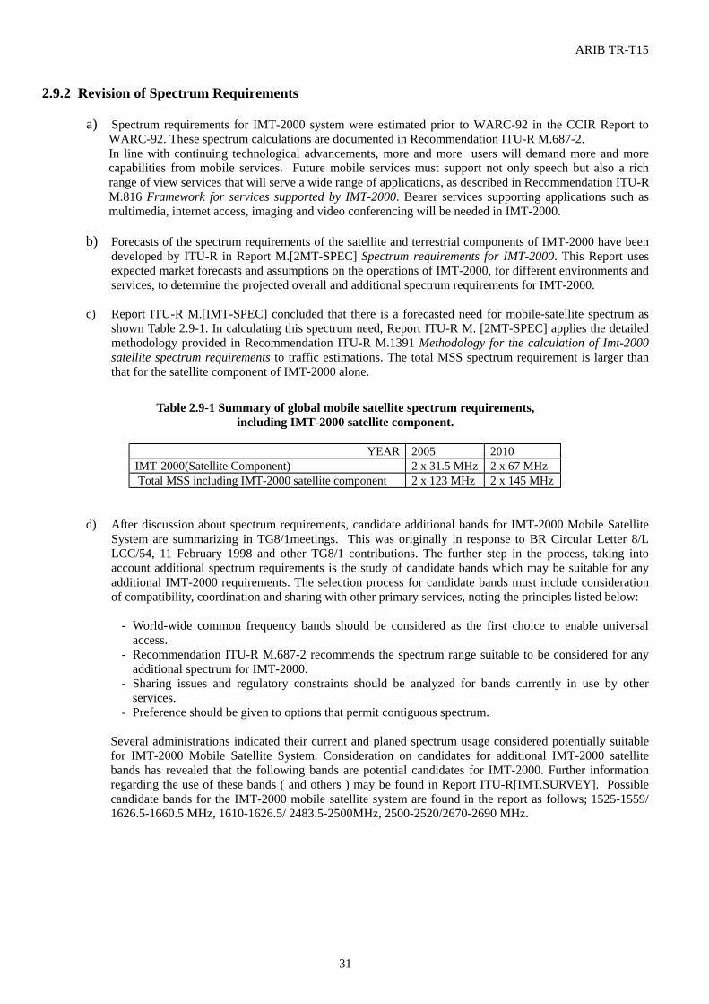
ARIB TR-T15
31
2.9.2 Revision of Spectrum Requirements a) Spectrum requirements for IMT-2000 system were estimated prior to WARC-92 in the CCIR Report to
WARC-92. These spectrum calculations are documented in Recommendation ITU-R M.687-2. In line with continuing technological advancements, more and more users will demand more and more
capabilities from mobile services. Future mobile services must support not only speech but also a rich range of view services that will serve a wide range of applications, as described in Recommendation ITU-R M.816 Framework for services supported by IMT-2000. Bearer services supporting applications such as multimedia, internet access, imaging and video conferencing will be needed in IMT-2000.
b) Forecasts of the spectrum requirements of the satellite and terrestrial components of IMT-2000 have been
developed by ITU-R in Report M.[2MT-SPEC] Spectrum requirements for IMT-2000. This Report uses expected market forecasts and assumptions on the operations of IMT-2000, for different environments and services, to determine the projected overall and additional spectrum requirements for IMT-2000.
c) Report ITU-R M.[IMT-SPEC] concluded that there is a forecasted need for mobile-satellite spectrum as
shown Table 2.9-1. In calculating this spectrum need, Report ITU-R M. [2MT-SPEC] applies the detailed methodology provided in Recommendation ITU-R M.1391 Methodology for the calculation of Imt-2000 satellite spectrum requirements to traffic estimations. The total MSS spectrum requirement is larger than that for the satellite component of IMT-2000 alone.
Table 2.9-1 Summary of global mobile satellite spectrum requirements,
including IMT-2000 satellite component.
YEAR 2005 2010 IMT-2000(Satellite Component) 2 x 31.5 MHz 2 x 67 MHz Total MSS including IMT-2000 satellite component 2 x 123 MHz 2 x 145 MHz
d) After discussion about spectrum requirements, candidate additional bands for IMT-2000 Mobile Satellite System are summarizing in TG8/1meetings. This was originally in response to BR Circular Letter 8/L LCC/54, 11 February 1998 and other TG8/1 contributions. The further step in the process, taking into account additional spectrum requirements is the study of candidate bands which may be suitable for any additional IMT-2000 requirements. The selection process for candidate bands must include consideration of compatibility, coordination and sharing with other primary services, noting the principles listed below:
- World-wide common frequency bands should be considered as the first choice to enable universal
access. - Recommendation ITU-R M.687-2 recommends the spectrum range suitable to be considered for any
additional spectrum for IMT-2000. - Sharing issues and regulatory constraints should be analyzed for bands currently in use by other
services. - Preference should be given to options that permit contiguous spectrum.
Several administrations indicated their current and planed spectrum usage considered potentially suitable for IMT-2000 Mobile Satellite System. Consideration on candidates for additional IMT-2000 satellite bands has revealed that the following bands are potential candidates for IMT-2000. Further information regarding the use of these bands ( and others ) may be found in Report ITU-R[IMT.SURVEY]. Possible candidate bands for the IMT-2000 mobile satellite system are found in the report as follows; 1525-1559/ 1626.5-1660.5 MHz, 1610-1626.5/ 2483.5-2500MHz, 2500-2520/2670-2690 MHz.
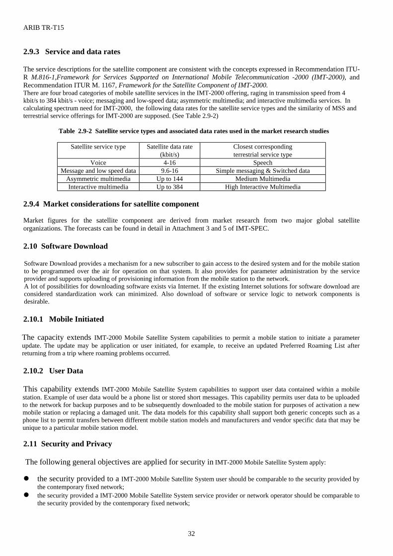
ARIB TR-T15
32
2.9.3 Service and data rates
The service descriptions for the satellite component are consistent with the concepts expressed in Recommendation ITU-R M.816-1,Framework for Services Supported on International Mobile Telecommunication -2000 (IMT-2000), and Recommendation ITUR M. 1167, Framework for the Satellite Component of IMT-2000. There are four broad categories of mobile satellite services in the IMT-2000 offering, raging in transmission speed from 4 kbit/s to 384 kbit/s - voice; messaging and low-speed data; asymmetric multimedia; and interactive multimedia services. In calculating spectrum need for IMT-2000, the following data rates for the satellite service types and the similarity of MSS and terrestrial service offerings for IMT-2000 are supposed. (See Table 2.9-2)
Table 2.9-2 Satellite service types and associated data rates used in the market research studies
Satellite service type Satellite data rate
(kbit/s) Closest corresponding terrestrial service type
Voice 4-16 Speech Message and low speed data 9.6-16 Simple messaging & Switched data
Asymmetric multimedia Up to 144 Medium Multimedia Interactive multimedia Up to 384 High Interactive Multimedia
2.9.4 Market considerations for satellite component Market figures for the satellite component are derived from market research from two major global satellite organizations. The forecasts can be found in detail in Attachment 3 and 5 of IMT-SPEC. 2.10 Software Download Software Download provides a mechanism for a new subscriber to gain access to the desired system and for the mobile station to be programmed over the air for operation on that system. It also provides for parameter administration by the service provider and supports uploading of provisioning information from the mobile station to the network. A lot of possibilities for downloading software exists via Internet. If the existing Internet solutions for software download are considered standardization work can minimized. Also download of software or service logic to network components is desirable. 2.10.1 Mobile Initiated The capacity extends IMT-2000 Mobile Satellite System capabilities to permit a mobile station to initiate a parameter update. The update may be application or user initiated, for example, to receive an updated Preferred Roaming List after returning from a trip where roaming problems occurred. 2.10.2 User Data This capability extends IMT-2000 Mobile Satellite System capabilities to support user data contained within a mobile station. Example of user data would be a phone list or stored short messages. This capability permits user data to be uploaded to the network for backup purposes and to be subsequently downloaded to the mobile station for purposes of activation a new mobile station or replacing a damaged unit. The data models for this capability shall support both generic concepts such as a phone list to permit transfers between different mobile station models and manufacturers and vendor specific data that may be unique to a particular mobile station model.
2.11 Security and Privacy The following general objectives are applied for security in IMT-2000 Mobile Satellite System apply: the security provided to a IMT-2000 Mobile Satellite System user should be comparable to the security provided by
the contemporary fixed network; the security provided a IMT-2000 Mobile Satellite System service provider or network operator should be comparable to
the security provided by the contemporary fixed network;
ARIB TR-T15
33
the legal, regulatory and commercial aspects of the security provided by IMT-2000 Mobile Satellite System should accommodate worldwide availability;
the security to be provided by IMT-2000 Mobile Satellite System should be adequately standardized to provide secure worldwide interoperability and roaming between different service providers and/or network operators;
provision should be made, so that legal interception of a user's communication be possible in accordance with national law;
IMT-2000 Mobile Satellite System should not utilize security provisions which are inherent features of the radio interface design so that any radio interface design can be adopted without diminishing the security and privacy.
(ITU-R M.1078, Sec.8.1) 2.11.1 High-level Requirement for Security and Private (extracts from ITU-R M.1078, Sec.8.2)
The following requirements apply to the security and privacy provision in IMT-2000 Mobile Satellite System : security features provided for the protection of the IMT-2000 Mobile Satellite System users should be user-friendly and
easy to use; They should, as far as possible, be transparent to the users, and should require a minimum of user-interaction on a per call basis;
security features provided for the protection of the IMT-2000 Mobile Satellite System users should not significantly increase call set-up times;
security features provided for the protection of the IMT-2000 Mobile Satellite System users should work without reduced security during handover and when roaming;
it should be very difficult for intruders to impersonate the IMT-2000 Mobile Satellite System user or network operators/service providers;
it should be very difficult to decipher the IMT-2000 Mobile Satellite System user's communication over the IMT-2000 Mobile Satellite System radio interfaces; This applies to any service information type or signaling information;
it should be very difficult for intruders to identify the IMT-2000 Mobile Satellite System users; it should be very difficult for intruders to physically locate the IMT-2000 Mobile Satellite System users; it should be possible for the IMT-2000 Mobile Satellite System network operator to identify an unauthorized or stolen
IMT-2000 Mobile Satellite System mobile terminals; the security to be provided by a IMT-2000 Mobile Satellite System should be adequately standardized to provide secure
international interoperability and roaming; However, within the security mechanisms of IMT-2000 Mobile Satellite System , the maximum independence between the parties involved in the IMT-2000 Mobile Satellite System operation should be allowed, as well as the maximum freedom for all parties to make their own security policies and mechanisms;
security key and possible devices, such as the User Identity Module (UIM), distributed to the IMT-2000 Mobile Satellite System users should be easily and securely managed and updated;
the security mechanisms provided by a IMT-2000 Mobile Satellite System should have a means for version management.
2.11.2 Security and Privacy Feature (extracts from ITU-R M.1078, Sec.8.3) A IMT-2000 Mobile Satellite System shall provide the following features related to security and privacy. 2.11.2.1 Access Control for Subscription and Service Profile Data This feature provides restrictions in the access to the personal data and the personal service profile of the IMT-2000 Mobile Satellite System user or subscriber stored in the network. 2.11.2.2 User Identity Authentication This feature provides a means by which the identity of the IMT-2000 Mobile Satellite System user is verified to be the one claimed in order for the service not to be compromised by the fraud use. 2.11.2.3 UIM Holder Verification This feature provides a means by which the human user of the UIM is authenticated to the UIM in order for the service not to accessed by theft or unauthorized person. This feature may be locally implemented without interaction with the network. 2.11.2.4 User Data Confidentiality This feature provides the privacy of communication by protecting the data of the 30 Mobile System user against interception over the IMT-2000 Mobile Satellite System radio interfaces. The feature applies to voice, or any other type of user data. 2.11.2.5 Signalling Information Confidentiality This feature provides a means by which the signalling information is protected against interception over the IMT-2000
ARIB TR-T15
34
Mobile Satellite radio interfaces. 2.11.2.6 User Identity Confidentiality This feature provides a means by which the identity of the IMT-2000 Mobile Satellite System user is protected against disclosure over the IMT-2000 Mobile Satellite System radio interfaces. 2.11.2.7 User Location Confidentiality This feature provides the privacy of the IMT-2000 Mobile Satellite System user by protecting the physical location of the user against disclosure over the IMT-2000 Mobile Satellite System radio interfaces. 2.11.2.8 Network Operator/Service Provider Authentication This feature provides a means by which the identity of the IMT-2000 Mobile Satellite System network operator/service provider is verified to be the one claimed. This feature may effectively be achieved by authenticating the network operator to which the user is accessing. 2.11.2.9 Re-authentication of User This feature provides a means by which the identity of the IMT-2000 Mobile Satellite System user is reverified to be the one claimed. This feature may be invoked repeatedly or at any appropriate instant. 2.11.2.10 Subscriber Access to Service This feature provides a means by which the IMT-2000 Mobile Satellite System subscriber has a direct and limited access to the personal service profile of him or his associated users, by means of which he may be able to restrict access to service, etc. 2.11.2.11 Version Control of Security Data and Mechanisms This feature provides a means by which security data and mechanisms can be updated and controlled between the parties involved. 2.12 Safety and Electromagnetic Compatibility (EMC) Requirement 2.12.1 Safety Requirement It is to be anticipated that, before IMT-2000 Mobile Satellite services commence, internationally agreed conditions for limits on thermal health hazards would be established. However, the non-thermal health hazards are also understudy especially where pulsed transmissions are investigated. IMT-2000 Mobile Satellite System equipments shall meet the requirements of the current relevant international safety requirements and legislation. In particular, in determining the radio link budget for the IMT-2000 Mobile Satellite System mobile station, the maximum power into the antenna and the antenna gain must be such that the user of the apparatus is not subject to RF radiation in excess of recommended safety limits. This is of particular importance for hand-portable mobile stations where the antenna will be close to the head and eyes of the user. The perceptions of the general public regarding issues of thermal and non-thermal health hazards are recognized, since they could have an impact on IMT-2000 Mobile Satellite service commencements. 2.12.2 Electromagnetic Compatibility The IMT-2000 Mobile Satellite System radio interface(s) shall be in accordance with appropriate EMC regulations. In the design of the IMT-2000 Mobile Satellite System radio interface(s), EMC performance shall be evaluated 2.13 Requirement for Interference with Other Systems 2.13.1 Interference to and from satellites In order to ensure the satisfactory coexistence of the terrestrial and space stations, it is important to be able to predict with reasonable accuracy the interference potential between them, using prediction procedures and models which are acceptable to all parties concerned, and which have demonstrated accuracy and reliability. Interference between terrestrial and space stations, between space stations in the same system, and between space
ARIB TR-T15
35
stations not in the same system can follow many paths. These can be summarized as follows:
1) Interference between space stations and earth stations not in the same system Mode B1 : a transmission from a space station of one space system causing interference to reception by an earth
station of another system. Mode B2 : a transmission from an earth station of one space system causing interference to reception by a space
station of another system. 2) Interference between space stations and terrestrial stations Mode C1 : a transmission from a space station causing interference to reception by a terrestrial station. Mode C2 : a transmission from a terrestrial station causing interference to reception by a space station.
For the above interference cases, the propagation and calculation methods in Annex 1 of Recommendation ITU-R P.619 can be used for the evaluation of interference between stations in space and those on the surface of the Earth. Recommendation ITU-R M.1036 provides the constraints on spectrum use include sharing with other land mobile, satellite and fixed service systems. In the recommendation, the results of theoretical calculations show that the normal assignment which assigns the lower band to the uplink (from mobile station to base station) is preferable to the reverse assignment. (see ITU-R M.1036-1, Sec.1.1.1) 2.13.2 Interference between mobile earth stations (MESs) and Other Systems In order to ensure the satisfactory coexistence of the terrestrial and Earth-space systems involved, it is important to be able to predict with reasonable accuracy the interference potential between them, using prediction procedures and models which are acceptable to all parties concerned, and which have demonstrated accuracy and reliability. Recommendation ITU-R P.452 can be used for the evaluation of the available propagation loss in interference calculations between stations on the surface of the Earth. Recommendation ITU-R M.1036 provides the constraints on spectrum use include sharing with other land mobile, satellite and fixed service systems. For the interference to mobile earth stations, studies have shown that the interference to the MESs of the satellite component of IMT-2000 would be increased also if the duplex direction is reversed. (see ITU-R M.1036-1, Sec.1.1.2) Recommendation ITU-R M.1343 provides the essential technical requirements including the maximum unwanted emission of mobile earth stations for global non-geostationary mobile-satellite systems in the bands 1-3 GHz. On the other hand, for global geostationary mobile-satellite systems in the bands 1-3 GHz, a new ITU-R recommendation for the maximum unwanted emission of such terminals are being under development. (see ITU-R M.1343, Annex 1 & 2 )
ARIB TR-T15
36
2.14 Location Services This section provides information regarding the Location Services (LCS) from the IMT-2000 MSS’s points of view. It should be noted that the Location Services may be service provider specific. However, the Location Services provided by IMT-2000 MSS should be basically same service level as in state of the location requirements of IMT-2000 terrestrial mobile systems as long as the satellite components of IMT-2000 Mobile System. In the case of IMT-2000 MSS, the geolocation information of a MES is required due to the following reasons:
- Efficient call to the MES - The MES’s geolocation information needs to determine whether the MES is located within the authorized
service area - To obtain the MES’s location information in the case of an emergency call from/to the MES - Value-added and supporting supplementary services.
In addition above, the geolocation information of a MES is an essential element for the LEO Satellite systems due to the following reasons:
- Satellite-to-satellite Handover - Routing for each call in order to obtain the most suitable Land Earth Station (LES)
In U.S.A., the FCC has adopted wireless E911 rules which specifies the location accuracy for all calls is 125 meters or less using Root Mean Square (RMS) methodology, as shown in APPENDIX to section 2.14. Since the IMT-2000 terrestrial system allow the requirement of location accuracy in accordance with national regulations as above, IMT-2000 MSS should accept the same functionality of the location accuracy. (See APPENDIX on this section)
ARIB TR-T15
37
APPENDIX (Section 2.14)
USA FCC Wireless E911 Rules
Action was taken by the FCC on September 15, 1999, with respect to E911 location technology by the Third Report and Order (FCC 99-245). The FCC has adopted the following revisions to its wireless E911 rules:
• Wireless carriers who employ a Phase II location technology that requires new, modified or upgraded handsets (such as GPS-based technologies) may phase-in deployment of Phase II subject to the following requirements:
- Without respect to any PSAP request for Phase II deployment, the carrier shall:
1. Begin selling and activating ALI-capable handsets no later than March 1, 2001; 2. Ensure that at least 50 percent of all new handsets activated are ALI-capable no
later than October 1, 2001; and 3. Ensure that at least 95 percent of all new digital handsets activated are ALI- capable no later than
October 1, 2002.
- Once a PSAP request is received, the carrier shall, in the area served by the PSAP: Within six months or by October 1, 2001, whichever is later:
1. Ensure that 100 percent of all new handsets activated are ALI-capable; 2. Implement any network upgrades or other steps necessary to locate handsets; and 3. Begin delivering to the PSAP location information that satisfies Phase II requirements.
Within two years or by December 31, 2004, whichever is later, undertake reasonable efforts to achieve 100 percent penetration of ALI-capable handsets in its total subscriber base.
• For roamers and other callers without ALI-capable handsets, carriers shall support Phase I ALI and other
available best practice methods of providing the location of the handset to the PSAP. • To be allowable under the FCC rules, an ALI technology that requires new, modified, or upgraded handsets
shall conform to general standards and be interoperable, allowing roaming among different carriers employing handset-based location technologies.
• For carriers employing network-based location technologies, the FCC replaces its current plan, which requires
that implementation be fully accomplished within 6 months of a PSAP request, with a revised rule requiring the carrier to deploy Phase II to 50 percent of callers within 6 months of a PSAP request and to 100 percent of callers within 18 months of such a request.
• The FCC adopts the following revised standards for Phase II location accuracy and reliability:
- For network-based solutions: 100 meters for 67 percent of calls, 300 meters for 95 percent of calls; - For handset-based solutions: 50 meters for 67 percent of calls, 150 meters for 95 percent of calls.
• The FCC directs wireless carriers to report their plans for implementing E911 Phase II, including the technology
they plan to use to provide caller location, by October 1, 2000. This report shall provide information to permit planning for Phase II implementation by public safety organizations, equipment manufacturers, local exchange carriers, and the FCC, in order to support Phase II deployment by October 1, 2001.
ARIB TR-T15
38
3. Consideration of Satellite Operating Environment 3.1 Radio Operating Environment A range of radio operating environments are applicable to IMT-2000, and are defined in this section. These are characterized by a range of environment attributes as seen by the IMT-2000 radio sub-system. The purpose of defining distinct IMT-2000 radio operating environments is to identify scenarios that, from a radio perspective, may impose different requirements on the radio interface(s). The purpose of identifying IMT-2000 radio operating environments is not to identify allowed scenarios for IMT-2000. The distinct IMT-2000 radio operating environments identified will serve as a basis for the further IMT-2000 system design process in order to identify commonalties and trade-offs, with the aim to minimize the number of IMT-2000 radio interfaces and to maximize the commonality between them. Four radio operating environments, Urban satellite environment, Rural satellite environment, Satellite fixed-mounted environment and Indoor satellite environment are described in detail below. In all cases the propagation ranges, mobile speeds, etc. represent typical values only, and are not meant to be restrictive. In all cases, the propagation path considered is between the mobile unit and its serving base station; that is, the second radio interface of a mobile base station or repeater lies outside the described environment. The expected service information rates, however, will be given by the weakest link in the chain. 3.1.1 Urban satellite environment The urban satellite environment encompasses outdoor propagation over ranges up to around 47,000 km in urban areas. Medium traffic requirements are expected in this environment. The mobile earth stations may be moving with zero to typical vehicular speeds (0-100 km/h), and the space stations (satellites) may be moving with speeds (relative to ground) from practically zero to satellite speeds (0-27,000 km/h). The range and the relative speed in this operating environment depend on the satellite configuration. Urban satellite propagation is characterised by frequent blocking of the signal and multipath mostly due to buildings, and space stations (satellites) located at varying elevations and positions. The varying elevations and positions for the IMT-2000 satellites depend on the satellite constellation. 3.1.2 Rural satellite environment The rural satellite environment encompasses outdoor propagation over ranges up to around 47,000 km in rural areas. Low traffic requirements are expected in this environment. The mobile earth stations may be moving with zero to aeronautical speeds (0-1,500 km/h), and the space stations (satellites) may be moving with speeds (relative to ground) from practically zero to satellite speeds (0-27,000 km/h). The range and the relative speed in this operating environment depend on the satellite configuration. Rural satellite propagation is characterised by line-of-sight and occasional shadowing, and space stations (satellites) located at varying elevations and positions. The varying elevations and positions for the IMT-2000 satellites depend on the satellite constellation. It should be noted that for the purposes of this Recommendation the rural satellite environment includes aeronautical and maritime. In these cases there may be significant differences to the rural land environment due to terminal speeds and propagation effects (e.g. multipath). 3.1.3 Satellite fixed-mounted environment The satellite fixed-mounted environment encompasses outdoor propagation over ranges up to around 47,000 km with stationary (fixed) mobile stations. Low traffic requirements are expected in this environment.
ARIB TR-T15
39
The mobile earth stations are stationary, and the space stations (satellites) may be moving with speeds (relative to ground) from practically zero to satellite speed (0-27,000 km/h). The range and the relative speed in this operating environment depend on the satellite configuration. The propagation in this fixed case is characterised by an optimised positioning of the mobile earth station, and possibly use of directive antennas, so that multipath and blocking possibly can be avoided to some extent. Depending on the satellite constellation, the base stations (satellites) may be located either in a fixed position or at varying elevations and positions. 3.1.4 Indoor satellite environment The indoor satellite environment encompasses outdoor propagation with an additional indoor component added to it, over ranges up to around 47,000 km. The indoor satellite environment is a special and restrictive case, with a very limited set of application areas, mostly restricted to paging. Very low traffic requirements are expected in this environment. The mobile earth stations may be moving with zero to pedestrian speeds (0-10 km/h), and the space stations (satellites) may be moving with speeds (relative to ground) from practically zero to satellite speeds (0-27,000 km/h). The range and the relative speed in this operating environment depend on the satellite configuration. The propagation in this case is characterised by an outdoor component which may be caused by blocking of the signal and multipath due to mountains, trees or buildings, with an additional indoor component requiring an additional margin of the order of 10-15 dB. The space stations (satellites) are located at varying elevations and positions. The varying elevations and positions for the IMT-2000 satellites depend on the satellite constellation. 3.2 Transmission Range and Satellite Constellations 3.2.1 Maximum transmission range Varies from a minimum of approximately 700 km when using LEOs (low-Earth-orbit satellites) to about 36,000 km for GSOs (geostationary-orbit satellites) and 47,000 km for HEOs (highly-inclined elliptical-orbit satellites). 3.2.2 Overall path loss prediction models The presence of a direct path between the satellite and the mobile user is generally a mandatory requirement. However, this direct path can suffer from additional attenuation from shadowing due to foliage, buildings and other man-made structures. The level of additional attenuation tends to increase when the path length through the obstacles increases. This occurs mainly when the elevation angle decreases. Data on foliage attenuation at 1.6 and 2.5 GHz can be found in the literature and can be appropriately scaled in frequency. Additional attenuation is also introduced by ionospheric and tropospheric disturbances. The former are essentially Faraday rotation and amplitude scintillation while the latter only appear for elevation angles below 5°. It should be noted that propagation impairments apply differently to the land, maritime and aeronautical satellite environments.
3.3 Propagation Delay and Doppler Variation 3.3.1 Multipath delay spreads R.m.s. delay spreads tend to be smaller than a few microseconds. 3.3.2 Maximum Doppler shifts When using GSOs, Doppler shifts are essentially determined by the satellite and user moving speeds, and ranges up to 2 kHz for land mobile and maritime, and up to 4 kHz for the aeronautical, satellite environments. When using
ARIB TR-T15
40
LEOs, Doppler shifts are essentially determined by the satellite speed, and range up to several tens of kHz with Doppler accelerations up to 350 Hz/s.
3.4 Propagation Models and Fading Satellite propagation normally includes a line of sight component and diffused/reflected multipath components, and hence tends to be Rician distributed with fading rates set by user and satellite motions; however, Rayleigh fading occurs when the line of sight path is obstructed. Time delay spreads are likely no more than a few tens or hundreds of nanoseconds and the levels of delayed components are low so that fading may be considered as flat in frequency for a channel with a bandwidth less than about 2 MHz. Doppler offsets and rates of change are dependent upon relative motion between user and satellite. Gross Doppler shift in the carrier is a function of satellite velocity while Doppler spreading is dependent on the motion of the mobile station. For satellite applications in general a Rician fading model should be used to assess the performance of the RTT. Further, the aspects of multipath propagation and the maximum Doppler shifts are taken into account. The gross Doppler shift in the carrier frequency due to the motion of the satellite and the mobile terminals should be included in the link level simulation. 3.4.1 Narrowband model In the narrowband case the Rician model is characterized by the sum of the direct path component and the diffused/reflected multipath components. When the direct path component is diminished due to shadowing, it becomes the Rayleigh fading. If z(t) and w(t) denote the complex low pass representation of the channel input and output, then:
)()()()( 110 tztgPtzPtw +=
where: P0 : strength of the direct component
P1 : strength of the multipath component
g1(t) : complex Gaussian process weighting the multipath component. The general amplitude distribution of the Rician channel is characterized by (probability density-function, pdf):
pdf a aP
Ia P
P
a PP( ) = ⋅ ⋅
− +
22
10
0
1
20
1e
The ratio c of P0 and P1 is the direct-to-multipath signal power ratio and is called the Rician factor, K, usually expressed in dB value as:
c log 10 )/P(P log 10 1 0 ==K
The Doppler spectrum of g(t) is described by the Rician case in § 3.4.3. The special case when P0 = 0, i.e. ∞= - K is called the Rayleigh fading channel and its amplitude distribution is characterized by:
pdf a aP
aP( ) = ⋅
−2
1
2
1e
with P1 as the mean received power. The Doppler spectrum of g(t) is described here by the classical case in § 3.4.3. Rician factor values in Table 3.4-1 should be considered. Note that the attenuation of the direct path component due
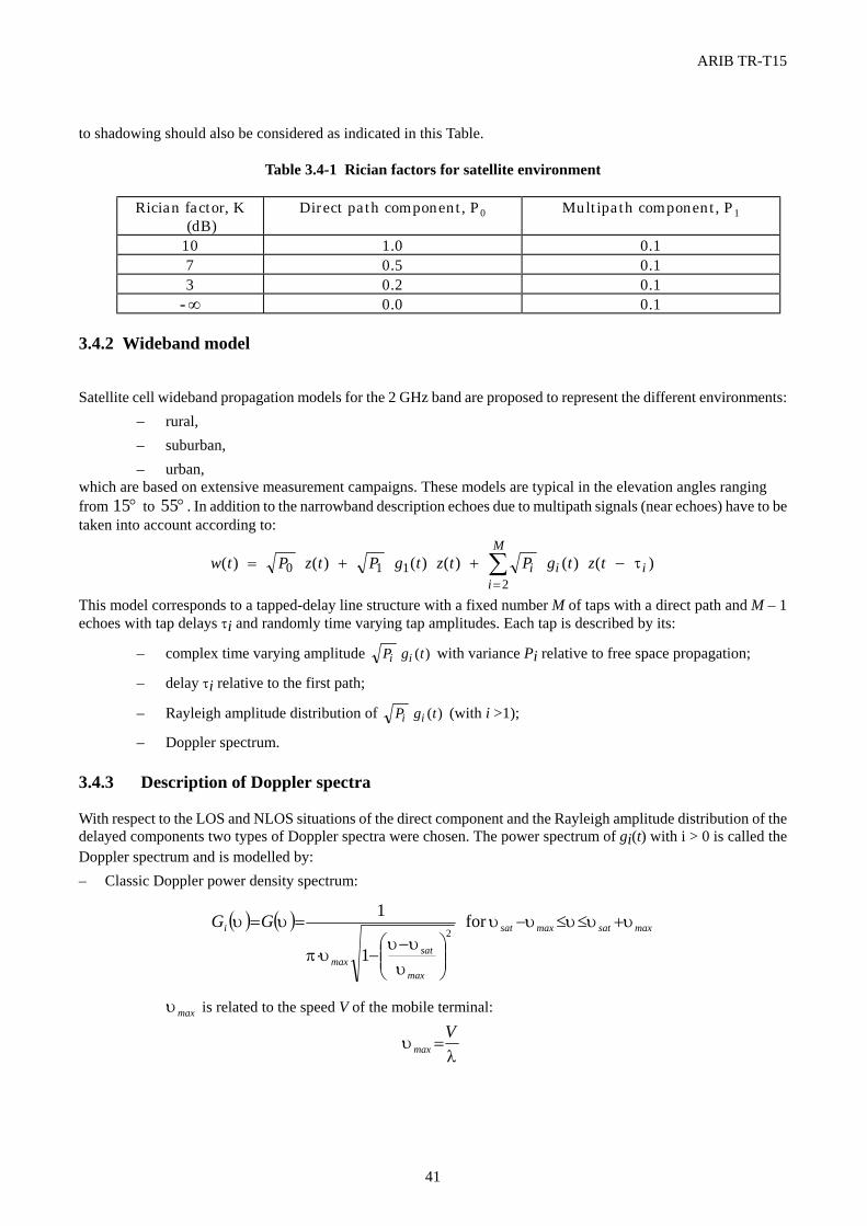
ARIB TR-T15
41
to shadowing should also be considered as indicated in this Table.
Table 3.4-1 Rician factors for satellite environment
Rician factor, K (dB)
Direct path component, P0 Multipath component, P1
10 1.0 0.1 7 0.5 0.1 3 0.2 0.1 ∞- 0.0 0.1
3.4.2 Wideband model
Satellite cell wideband propagation models for the 2 GHz band are proposed to represent the different environments: – rural, – suburban, – urban,
which are based on extensive measurement campaigns. These models are typical in the elevation angles ranging from °15 to °55 . In addition to the narrowband description echoes due to multipath signals (near echoes) have to be taken into account according to:
w t P z t P g t z t P g t z ti i ii
M( ) ( ) ( ) ( ) ( ) ( )= + + −
=∑0 1 1
2τ
This model corresponds to a tapped-delay line structure with a fixed number M of taps with a direct path and M – 1 echoes with tap delays τi and randomly time varying tap amplitudes. Each tap is described by its:
– complex time varying amplitude P g ti i ( ) with variance Pi relative to free space propagation;
– delay τi relative to the first path;
– Rayleigh amplitude distribution of P g ti i ( ) (with i >1);
– Doppler spectrum. 3.4.3 Description of Doppler spectra With respect to the LOS and NLOS situations of the direct component and the Rayleigh amplitude distribution of the delayed components two types of Doppler spectra were chosen. The power spectrum of gi(t) with i > 0 is called the Doppler spectrum and is modelled by: – Classic Doppler power density spectrum:
( ) ( ) maxsatmaxsat
max
satmax
i GG υυυυυ
υυυ
υπ
υυ +≤≤−
−−⋅
== for
1
12
maxυ is related to the speed V of the mobile terminal:
λ
υV
max =
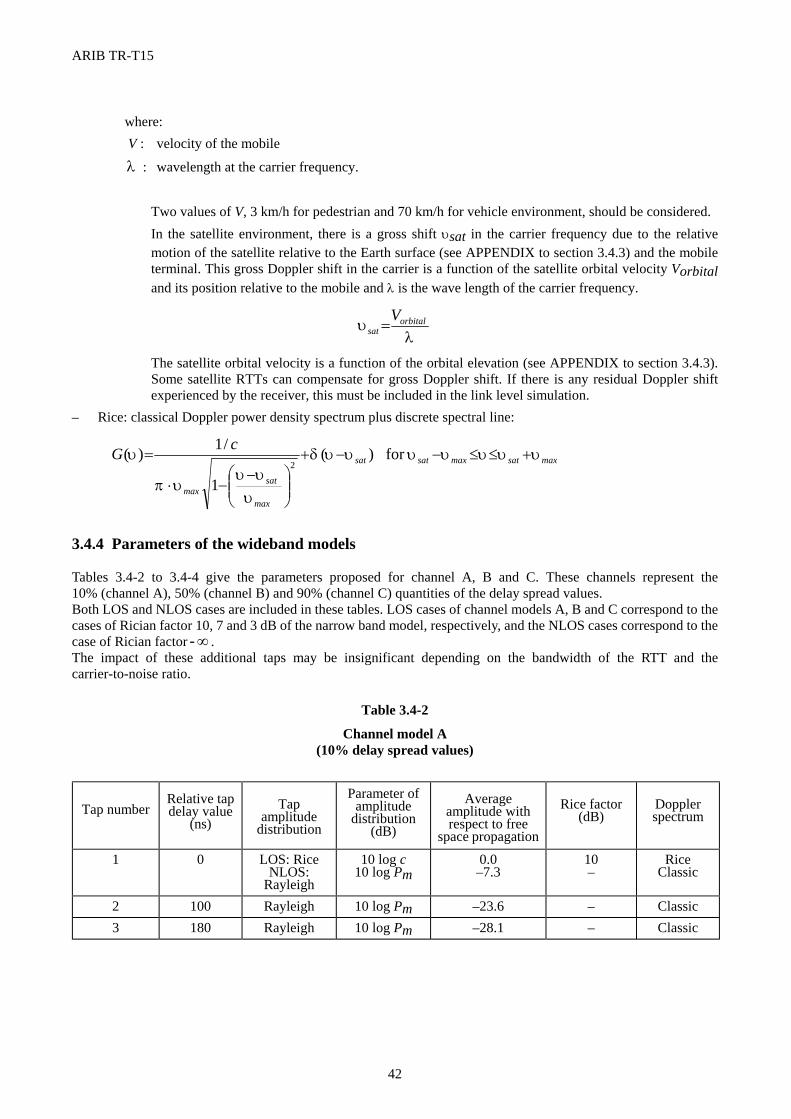
ARIB TR-T15
42
where: V : velocity of the mobile
λ : wavelength at the carrier frequency. Two values of V, 3 km/h for pedestrian and 70 km/h for vehicle environment, should be considered. In the satellite environment, there is a gross shift υsat in the carrier frequency due to the relative
motion of the satellite relative to the Earth surface (see APPENDIX to section 3.4.3) and the mobile terminal. This gross Doppler shift in the carrier is a function of the satellite orbital velocity Vorbital and its position relative to the mobile and λ is the wave length of the carrier frequency.
λ
υ orbitalsat
V=
The satellite orbital velocity is a function of the orbital elevation (see APPENDIX to section 3.4.3). Some satellite RTTs can compensate for gross Doppler shift. If there is any residual Doppler shift experienced by the receiver, this must be included in the link level simulation.
– Rice: classical Doppler power density spectrum plus discrete spectral line:
maxsatmaxsatsat
max
satmax
cG υυυυυυυδ
υυυ
υπ
υ +≤≤−−+
−−⋅
= for )(
1
/1)(2
3.4.4 Parameters of the wideband models Tables 3.4-2 to 3.4-4 give the parameters proposed for channel A, B and C. These channels represent the 10% (channel A), 50% (channel B) and 90% (channel C) quantities of the delay spread values. Both LOS and NLOS cases are included in these tables. LOS cases of channel models A, B and C correspond to the cases of Rician factor 10, 7 and 3 dB of the narrow band model, respectively, and the NLOS cases correspond to the case of Rician factor ∞- . The impact of these additional taps may be insignificant depending on the bandwidth of the RTT and the carrier-to-noise ratio.
Table 3.4-2
Channel model A (10% delay spread values)
Tap number Relative tap delay value
(ns) Tap
amplitude distribution
Parameter of amplitude
distribution (dB)
Average amplitude with respect to free
space propagation
Rice factor (dB)
Doppler spectrum
1 0 LOS: Rice NLOS:
Rayleigh
10 log c 10 log Pm
0.0 –7.3
10 –
Rice Classic
2 100 Rayleigh 10 log Pm –23.6 – Classic 3 180 Rayleigh 10 log Pm –28.1 – Classic
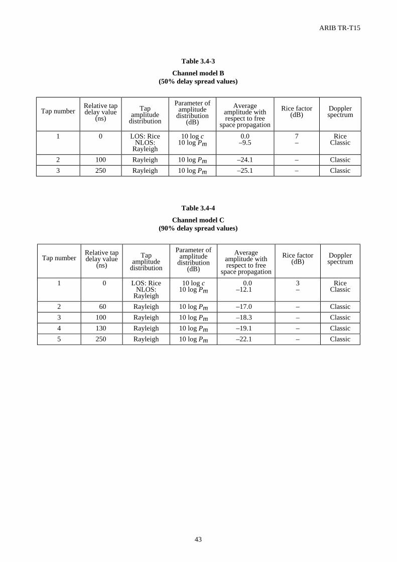
ARIB TR-T15
43
Table 3.4-3
Channel model B (50% delay spread values)
Table 3.4-4
Channel model C (90% delay spread values)
Tap number Relative tap delay value
(ns) Tap
amplitude distribution
Parameter of amplitude
distribution (dB)
Average amplitude with respect to free
space propagation
Rice factor (dB)
Doppler spectrum
1 0 LOS: Rice NLOS:
Rayleigh
10 log c 10 log Pm
0.0 –9.5
7 –
Rice Classic
2 100 Rayleigh 10 log Pm –24.1 – Classic 3 250 Rayleigh 10 log Pm –25.1 – Classic
Tap number Relative tap delay value
(ns) Tap
amplitude distribution
Parameter of amplitude
distribution (dB)
Average amplitude with respect to free
space propagation
Rice factor (dB)
Doppler spectrum
1 0 LOS: Rice NLOS:
Rayleigh
10 log c 10 log Pm
0.0 –12.1
3 –
Rice Classic
2 60 Rayleigh 10 log Pm –17.0 – Classic 3 100 Rayleigh 10 log Pm –18.3 – Classic 4 130 Rayleigh 10 log Pm –19.1 – Classic 5 250 Rayleigh 10 log Pm –22.1 – Classic
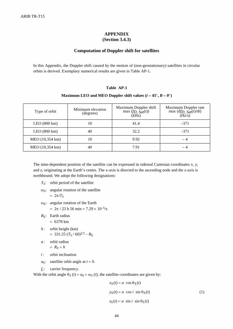
ARIB TR-T15
44
APPENDIX (Section 3.4.3)
Computation of Doppler shift for satellites
In this Appendix, the Doppler shift caused by the motion of (non-geostationary) satellites in circular orbits is derived. Exemplary numerical results are given in Table AP-1.
Table AP-1
Maximum LEO and MEO Doppler shift values (i = 45°, B = 0°)
The time-dependent position of the satellite can be expressed in sidereal Cartesian coordinates x, y, and z, originating at the Earth’s centre. The x-axis is directed to the ascending node and the z-axis is northbound. We adopt the following designations:
TS : orbit period of the satellite
ωS : angular rotation of the satellite = 2π/TS
ωE : angular rotation of the Earth = 2π / 23 h 56 min = 7.29 × 10⁻⁵/s
RE : Earth radius = 6378 km
h : orbit height (km) = 331.25 (TS / 60)2/3 – RE
a : orbit radius = RE + h
i : orbit inclination
u0 : satellite orbit angle at t = 0.
fc : carrier frequency. With the orbit angle θS (t) = u0 + ωS (t), the satellite coordinates are given by:
xS (t) = a cos θS (t)
yS (t) = a cos i sin θS (t) (1)
zS (t) = a sin i sin θS (t)
Type of orbit Minimum elevation (degrees)
Maximum Doppler shift max (fD, Sat(t))
(kHz)
Maximum Doppler rate max (dfD, Sat(t)/dt)
(Hz/s)
LEO (800 km) 10 41.4 –371
LEO (800 km) 40 32.2 –371
MEO (10,354 km) 10 9.92 – 4
MEO (10,354 km) 40 7.91 – 4
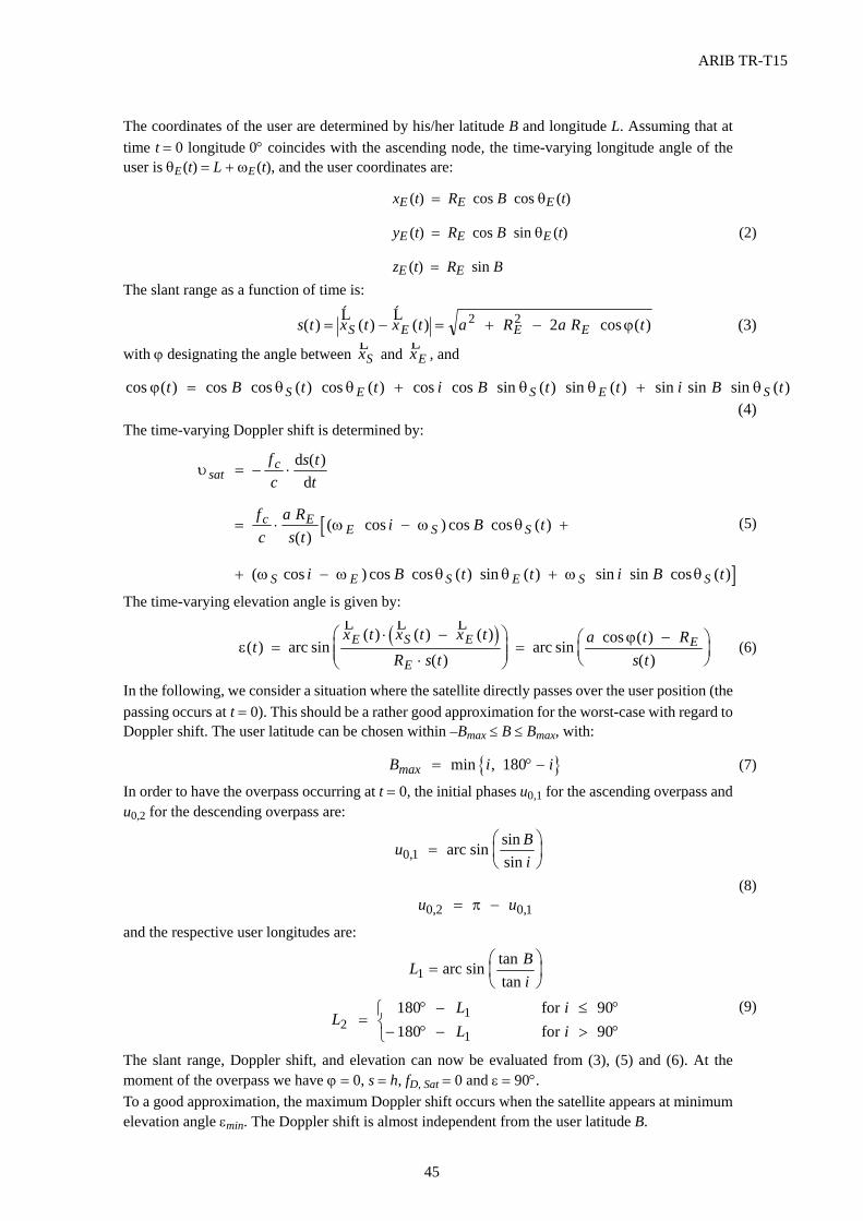
ARIB TR-T15
45
The coordinates of the user are determined by his/her latitude B and longitude L. Assuming that at time t = 0 longitude 0° coincides with the ascending node, the time-varying longitude angle of the user is θE (t) = L + ωE (t), and the user coordinates are:
xE (t) = RE cos B cos θE (t)
yE (t) = RE cos B sin θE (t) (2)
zE (t) = RE sin B The slant range as a function of time is:
s t x t x t a R a R tS E E E( ) ( ) ( ) cos ( )= − = + −r r 2 2 2 ϕ (3)
with ϕ designating the angle between rxS and rxE , and
cos ( ) cos cos ( ) cos ( ) cos cos sin ( ) sin ( ) sin sin sin ( )ϕ θ θ θ θ θt B t t i B t t i B tS E S E S= + + (4) The time-varying Doppler shift is determined by:
υ satcf
cs t
t= ⋅– ( )d
d
[= ⋅ − +fc
a Rs t
i B tc EE S S( )
( cos ) cos cos ( )ω ω θ (5)
]+ − +( cos ) cos cos ( ) sin ( ) sin sin cos ( )ω ω θ θ ω θS E S E S Si B t t i B t
The time-varying elevation angle is given by:
( )
εϕ( ) sin
( ) ( ) ( )( )
sin cos ( )( )
tx t x t x t
R s ta t R
s tE S E
E
E=⋅ −
⋅
=
−
arc arc
r r r (6)
In the following, we consider a situation where the satellite directly passes over the user position (the passing occurs at t = 0). This should be a rather good approximation for the worst-case with regard to Doppler shift. The user latitude can be chosen within –Bmax ≤ B ≤ Bmax, with:
{ }B i imax = ° −min , 180 (7)
In order to have the overpass occurring at t = 0, the initial phases u0,1 for the ascending overpass and u0,2 for the descending overpass are:
u Bi0 1, sin sin
sin=
arc
(8) u u0 2 0 1, ,= −π
and the respective user longitudes are:
L Bi1 =
arc tan
tansin
LLL
ii2
1
1
180180
9090
=° −
− ° −
≤ °> °
forfor
(9)
The slant range, Doppler shift, and elevation can now be evaluated from (3), (5) and (6). At the moment of the overpass we have ϕ = 0, s = h, fD, Sat = 0 and ε = 90°. To a good approximation, the maximum Doppler shift occurs when the satellite appears at minimum elevation angle εmin. The Doppler shift is almost independent from the user latitude B.
ARIB TR-T15
46
4. Overview of MSS Radio Interface 4.1 Selection of Radio Transmission System 4.1.1 Key Parameters for Selection of Radio Transmission System The Parameters of MSS Radio Transmission Systems should be selected to meet the QoS (User data rate, BER, Delay in PLMN and condition of propagation) and transmission power limitation of Mobile Earth Station 4.1.1.1 Support of Wide Rang Data rate Minimum user data rate for Bearer Channel of 3G Mobile Satellite System is listed in Table 4.2-1. Adoption of higher data rate services is desirable for the benefit of users, but it depends on operator’s decision from the viewpoints of effective operation. Proposed values of Minimum user data rate for Bearer Channels comes from the limitation of Transmission power and Bandwidth of MSS. Service deployment of same applications of 3G Terrestrial System to 3G MSS users such as high data rate transmission and image information transmission to users, is also desirable. The technologies to be adopted for 3G MSS should be selected from well developed technologies, because MSS system is required stable operation more longer period of its life time. During its long operational lifetime the 3G MSS radio interfaces should have capability of service enhancements and wide range of transmission rate. The flexibility of transmission rate is a key factor of the selection for the MSS radio interfaces. 4.1.1.2 Support Connectionless Communication Services The capability of connectionless communication services such as Internet service is a most expected function of the 3G MSS. Packet data switched mode service with higher bit rate is desirable rather than circuit switched mode service from the view point of effective usages of radio resources. The service costs for users will be dramatically reduced because of its effectiveness by the adoption of packet mode-connectionless communication. For secure of sufficient QoS in the various environments, the adequate transmission power control function is required under the various fading conditions. On the other hand, excessive transmission power caused some interference to other users, low transmission power caused higher error rate and can not guarantee the QoS for example. Since MSS has fundamentary a large value of propagation delay and its delay causes Transmission Power Control error, it will be necessary to adopt some adequate advanced Transmission Power Control Methods and Protocol in addition to the basic Terrestrial Mobile system's one. Although the support of Connectionless Communication services may be essential for Low orbit satellite (NGEO) systems, the support of Connectionless Communication services for the GEO systems should depend on the operator's discretion. 4.1.1.3 Commonality between IMT-2000 Terrestrial Mobile System(s) and 3G MSS(s) The Support of Roaming function between IMT-2000 Terrestrial Mobile Systems and 3G MSS(s) within its service area is desirable for a Mobile Satellite Terminal. To make its easy implementation on a small and lightweight MSS mobile terminal, technical commonality between IMT-2000 Terrestrial Mobile System(s) and 3G MSS(s) should be managed to maximum procure at the satellite radio interface. The large commonalities between each systems make it possible to deliver some common hardware such as
ARIB TR-T15
47
chip-set or software and it will be effective for terminal cost reduction. The cost reduction of the Mobile Satellite Terminal is key factor to ensure the early market deployment. Therefore, the satellite radio interface of future 3G MSS should be standardized based on the specifications of the radio interfaces of IMT-2000 Terrestrial Mobile systems. 4.1.2 Selection of CDMA as the Radio Transmission Technology Six detailed specifications of the radio interfaces of IMT-2000 MSS was accepted at the ITU-R TG8/1 18th meeting and ITU SG8 in November 10-12, 1999. The titles and proponent of specification are listed as below. ③ SRI-A, SW-CDMA Chip rate=1.92 or 3.84 Mcps (ESA) ④ SRI-B, W-C/TDMA Chip rate=1.92 or 3.84 Mcps(ESA) ⑤ SRI-C, SAT-CDMA Chip rate=3.84 Mcps (Korea) ⑥ SRI-D, TDMA/FDMA (ICO) ⑥ SRI-E, TDMA (Inmarsat) ② SRI-F,Satcom2000 FDMA/TDMA and FDMA/CDMA Chip rate=1.228 to 4.096 Mcps (Iridium/America) Some of the accepted SRIs are similar to 2G Terrestrial Mobile systems or it's extended systems. Most of the accepted SRIs are adopted CDMA technologies. Since it takes several years to make a plan, design, manufacturing and development of its actual MSS system, new 3G MSS should introduce 3G Radio Transmission Technologies for the Terrestrial Mobile systems as much as possible. Five Detailed Specifications of the Radio interfaces of IMT-2000 Terrestrial Mobile systems was accepted at the ITU-R TG8/1 18th meeting and ITU SG8 in November 10-12, 1999. The titles and proponent of specifications are listed below. ① IMT-2000 CDMA Direct Spread (3GPP/FDD) ② IMT-2000 CDMA Multi-Carrier (3GPP2/cdma2000) ③ IMT-2000 CDMA TDD (3GPP/TDD+China/TD-SCDMA) ④ IMT-2000 TDMA Single Carrier (UWC-136) ⑤ IMT-2000 FDMA/TDMA (DECT) Two TDMA systems was accepted as IMT-2000 Terrestrial RSPCs. One is an extended Specification from 2G Terrestrial Mobile systems called DECT, the another one is an extended Specification from 2G Terrestrial Mobile systems called IS-136 that is operated as Cellular and PCS systems in US. The TDMA systems is considered as specific regional standards in actual system deployment in the world. On the contrary, the CDMA systems was standardized by world wide standard development organizations and are considered as global standards to be used world widely. The Radio Transmission Technologies of IMT-2000 CDMA Direct Spread and IMT-2000 CDMA TDD was standardized world widely by Third Generation Partnership Project(3GPP) organized with ARIB(Japan), CWTS(China), ETSI(EU), TTA(Korea), TTC(Japan), T1(US). The Radio Transmission Technologies of IMT-2000 CDMA Multi-Carrier was standardized world widely by Third Generation Partnership Project 2(3GPP2) organized with ARIB(Japan), CWTS(China), TIA(US), TTA(Korea) and TTC(Japan). In conclusion, Satellite Radio interfaces of 3G MSS should introduce 3G Radio Transmission Technologies that will be adopted to Terrestrial Mobile systems or that is at least CDMA technologies.
ARIB TR-T15
48
Although CDMA technologies have large commonality, there are many modes in its detail specifications such as Direct Spread, Multi-Carrier, TDD, FDD and so on. Of course, each system integrations are different from each others, therefore, the selection of CDMA technologies should be operator's discretion. 4.2 Technical Requirement for 3G Mobile Satellite Systems This section describes the technical requirements to satisfy the minimum requirement of satellite IMT-2000 mobile systems described in chapter 2.7 of this volume and discuss the possibility to realize the satellite stations. To discuss technical requirements of satellite stations and the possibility to realize technical requirements, following items are presumed. (1) Satellite IMT-2000 mobile earth stations are realized by using currently possible techniques. (2) Handling of satellite IMT-2000 mobile earth stations is not so different from that of terrestrial IMT-2000
mobile terminal stations. (3) The channel capacity is calculated by using the half of frequency band assigned for satellite IMT-2000 i.e.
15 MHz for each of up link and down link. 4.2.1 Technical Requirement to Satisfy Minimum Requirements 4.2.1.1 Definition of Minimum Requirements (1) User data rate
Minimum user data rate supported by satellite IMT-2000 mobile earth station is shown in Table 4.2-1. Minimum user data rate means the minimum bit rate which satellite IMT-2000 mobile earth station should support. User data rate more than these values and less than these values are possible to support by operator's decision.
Table 4.2-1 Minimum user data rate
Minimum user data rate
Type of mobile earth station Operating environment Speech
(Telephone) Circuit
switched data Packet
switched data Hand held Urban, Rural 2.4 kbit/s 9.6 kbit/s 9.6 kbit/s Portable Urban, Rural 2.4 kbit/s 32 kbit/s 64 kbit/s Vehicular mounted Urban, Rural 2.4 kbit/s 32 kbit/s 64 kbit/s Fixed mounted Fixed-mounted 2.4 kbit/s 32 kbit/s 64 kbit/s Paging receiver Urban, Rural, Indoor − − 1.2 kbit/s
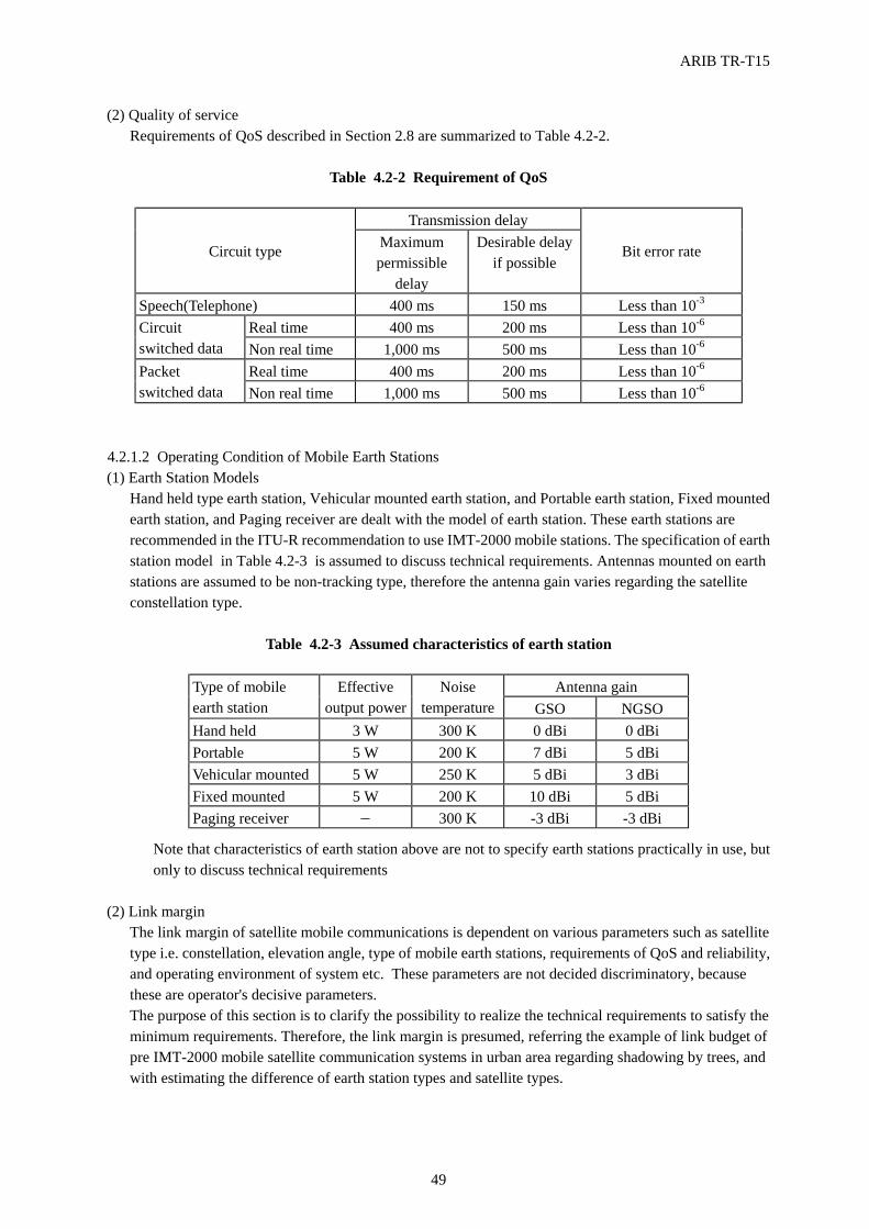
ARIB TR-T15
49
(2) Quality of service Requirements of QoS described in Section 2.8 are summarized to Table 4.2-2.
Table 4.2-2 Requirement of QoS
Transmission delay
Circuit type Maximum permissible
delay
Desirable delay if possible Bit error rate
Speech(Telephone) 400 ms 150 ms Less than 10-3 Real time 400 ms 200 ms Less than 10-6 Circuit
switched data Non real time 1,000 ms 500 ms Less than 10-6 Real time 400 ms 200 ms Less than 10-6 Packet
switched data Non real time 1,000 ms 500 ms Less than 10-6
4.2.1.2 Operating Condition of Mobile Earth Stations (1) Earth Station Models
Hand held type earth station, Vehicular mounted earth station, and Portable earth station, Fixed mounted earth station, and Paging receiver are dealt with the model of earth station. These earth stations are recommended in the ITU-R recommendation to use IMT-2000 mobile stations. The specification of earth station model in Table 4.2-3 is assumed to discuss technical requirements. Antennas mounted on earth stations are assumed to be non-tracking type, therefore the antenna gain varies regarding the satellite constellation type.
Table 4.2-3 Assumed characteristics of earth station
Antenna gain Type of mobile
earth station Effective
output power Noise
temperature GSO NGSO Hand held 3 W 300 K 0 dBi 0 dBi Portable 5 W 200 K 7 dBi 5 dBi Vehicular mounted 5 W 250 K 5 dBi 3 dBi Fixed mounted 5 W 200 K 10 dBi 5 dBi Paging receiver − 300 K -3 dBi -3 dBi
Note that characteristics of earth station above are not to specify earth stations practically in use, but only to discuss technical requirements
(2) Link margin
The link margin of satellite mobile communications is dependent on various parameters such as satellite type i.e. constellation, elevation angle, type of mobile earth stations, requirements of QoS and reliability, and operating environment of system etc. These parameters are not decided discriminatory, because these are operator's decisive parameters. The purpose of this section is to clarify the possibility to realize the technical requirements to satisfy the minimum requirements. Therefore, the link margin is presumed, referring the example of link budget of pre IMT-2000 mobile satellite communication systems in urban area regarding shadowing by trees, and with estimating the difference of earth station types and satellite types.
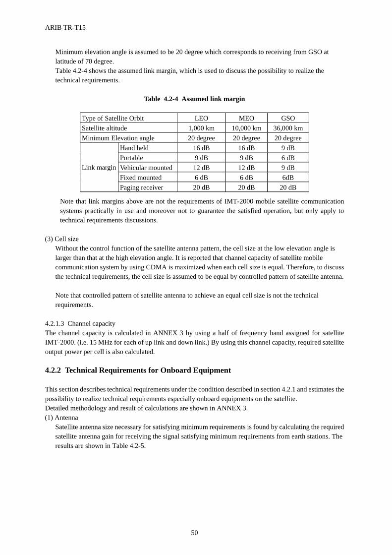
ARIB TR-T15
50
Minimum elevation angle is assumed to be 20 degree which corresponds to receiving from GSO at latitude of 70 degree. Table 4.2-4 shows the assumed link margin, which is used to discuss the possibility to realize the technical requirements.
Table 4.2-4 Assumed link margin
Type of Satellite Orbit LEO MEO GSO Satellite altitude 1,000 km 10,000 km 36,000 km Minimum Elevation angle 20 degree 20 degree 20 degree
Hand held 16 dB 16 dB 9 dB Portable 9 dB 9 dB 6 dB Vehicular mounted 12 dB 12 dB 9 dB Fixed mounted 6 dB 6 dB 6dB
Link margin
Paging receiver 20 dB 20 dB 20 dB
Note that link margins above are not the requirements of IMT-2000 mobile satellite communication systems practically in use and moreover not to guarantee the satisfied operation, but only apply to technical requirements discussions.
(3) Cell size
Without the control function of the satellite antenna pattern, the cell size at the low elevation angle is larger than that at the high elevation angle. It is reported that channel capacity of satellite mobile communication system by using CDMA is maximized when each cell size is equal. Therefore, to discuss the technical requirements, the cell size is assumed to be equal by controlled pattern of satellite antenna. Note that controlled pattern of satellite antenna to achieve an equal cell size is not the technical requirements.
4.2.1.3 Channel capacity The channel capacity is calculated in ANNEX 3 by using a half of frequency band assigned for satellite IMT-2000. (i.e. 15 MHz for each of up link and down link.) By using this channel capacity, required satellite output power per cell is also calculated. 4.2.2 Technical Requirements for Onboard Equipment This section describes technical requirements under the condition described in section 4.2.1 and estimates the possibility to realize technical requirements especially onboard equipments on the satellite. Detailed methodology and result of calculations are shown in ANNEX 3. (1) Antenna
Satellite antenna size necessary for satisfying minimum requirements is found by calculating the required satellite antenna gain for receiving the signal satisfying minimum requirements from earth stations. The results are shown in Table 4.2-5.
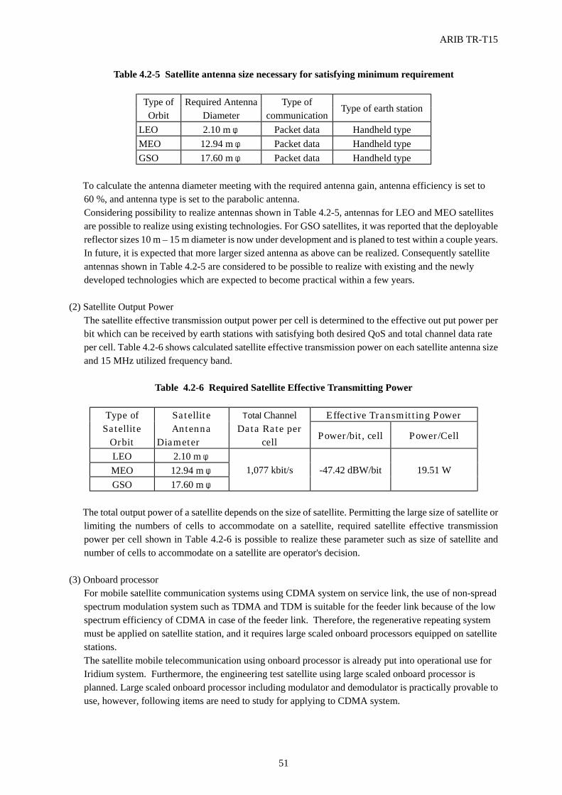
ARIB TR-T15
51
Table 4.2-5 Satellite antenna size necessary for satisfying minimum requirement
Type of Orbit
Required Antenna Diameter
Type of communication
Type of earth station
LEO 2.10 m φ Packet data Handheld type MEO 12.94 m φ Packet data Handheld type GSO 17.60 m φ Packet data Handheld type
To calculate the antenna diameter meeting with the required antenna gain, antenna efficiency is set to
60 %, and antenna type is set to the parabolic antenna. Considering possibility to realize antennas shown in Table 4.2-5, antennas for LEO and MEO satellites are possible to realize using existing technologies. For GSO satellites, it was reported that the deployable reflector sizes 10 m – 15 m diameter is now under development and is planed to test within a couple years. In future, it is expected that more larger sized antenna as above can be realized. Consequently satellite antennas shown in Table 4.2-5 are considered to be possible to realize with existing and the newly developed technologies which are expected to become practical within a few years.
(2) Satellite Output Power
The satellite effective transmission output power per cell is determined to the effective out put power per bit which can be received by earth stations with satisfying both desired QoS and total channel data rate per cell. Table 4.2-6 shows calculated satellite effective transmission power on each satellite antenna size and 15 MHz utilized frequency band.
Table 4.2-6 Required Satellite Effective Transmitting Power
Effective Transmitting Power Type of Satellite
Orbit
Satellite Antenna
Diameter
Total Channel Data Rate per
cell Power/bit, cell Power/Cell LEO 2.10 m φ MEO 12.94 m φ GSO 17.60 m φ
1,077 kbit/s -47.42 dBW/bit 19.51 W
The total output power of a satellite depends on the size of satellite. Permitting the large size of satellite or
limiting the numbers of cells to accommodate on a satellite, required satellite effective transmission power per cell shown in Table 4.2-6 is possible to realize these parameter such as size of satellite and number of cells to accommodate on a satellite are operator's decision.
(3) Onboard processor
For mobile satellite communication systems using CDMA system on service link, the use of non-spread spectrum modulation system such as TDMA and TDM is suitable for the feeder link because of the low spectrum efficiency of CDMA in case of the feeder link. Therefore, the regenerative repeating system must be applied on satellite station, and it requires large scaled onboard processors equipped on satellite stations. The satellite mobile telecommunication using onboard processor is already put into operational use for Iridium system. Furthermore, the engineering test satellite using large scaled onboard processor is planned. Large scaled onboard processor including modulator and demodulator is practically provable to use, however, following items are need to study for applying to CDMA system.
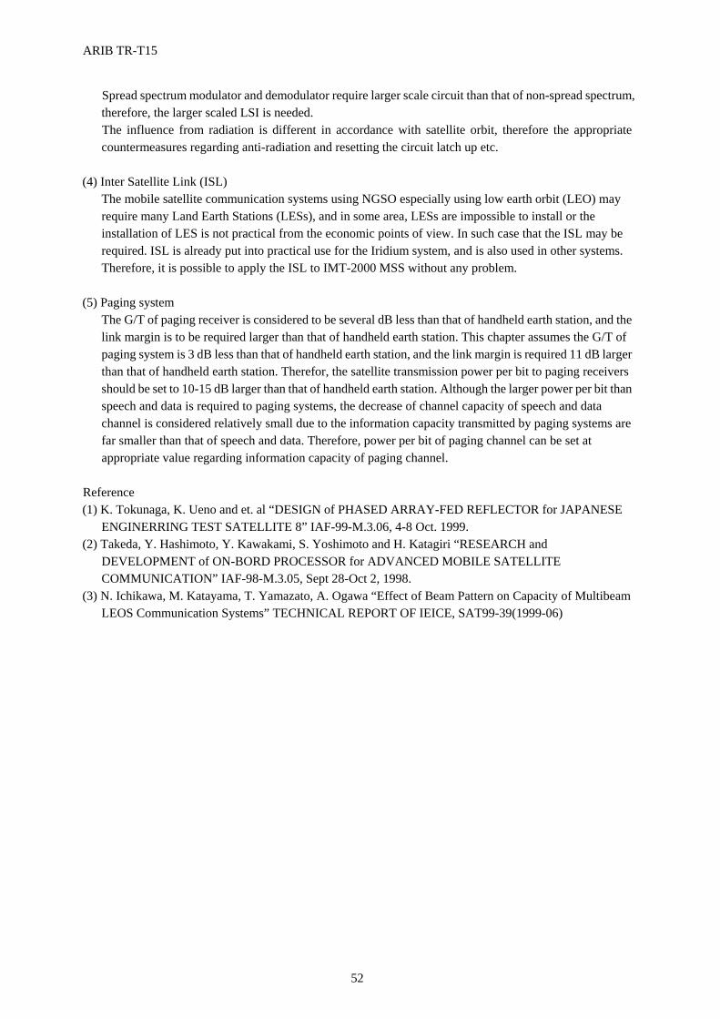
ARIB TR-T15
52
Spread spectrum modulator and demodulator require larger scale circuit than that of non-spread spectrum, therefore, the larger scaled LSI is needed. The influence from radiation is different in accordance with satellite orbit, therefore the appropriate countermeasures regarding anti-radiation and resetting the circuit latch up etc.
(4) Inter Satellite Link (ISL)
The mobile satellite communication systems using NGSO especially using low earth orbit (LEO) may require many Land Earth Stations (LESs), and in some area, LESs are impossible to install or the installation of LES is not practical from the economic points of view. In such case that the ISL may be required. ISL is already put into practical use for the Iridium system, and is also used in other systems. Therefore, it is possible to apply the ISL to IMT-2000 MSS without any problem.
(5) Paging system
The G/T of paging receiver is considered to be several dB less than that of handheld earth station, and the link margin is to be required larger than that of handheld earth station. This chapter assumes the G/T of paging system is 3 dB less than that of handheld earth station, and the link margin is required 11 dB larger than that of handheld earth station. Therefor, the satellite transmission power per bit to paging receivers should be set to 10-15 dB larger than that of handheld earth station. Although the larger power per bit than speech and data is required to paging systems, the decrease of channel capacity of speech and data channel is considered relatively small due to the information capacity transmitted by paging systems are far smaller than that of speech and data. Therefore, power per bit of paging channel can be set at appropriate value regarding information capacity of paging channel.
Reference (1) K. Tokunaga, K. Ueno and et. al “DESIGN of PHASED ARRAY-FED REFLECTOR for JAPANESE
ENGINERRING TEST SATELLITE 8” IAF-99-M.3.06, 4-8 Oct. 1999. (2) Takeda, Y. Hashimoto, Y. Kawakami, S. Yoshimoto and H. Katagiri “RESEARCH and
DEVELOPMENT of ON-BORD PROCESSOR for ADVANCED MOBILE SATELLITE COMMUNICATION” IAF-98-M.3.05, Sept 28-Oct 2, 1998.
(3) N. Ichikawa, M. Katayama, T. Yamazato, A. Ogawa “Effect of Beam Pattern on Capacity of Multibeam LEOS Communication Systems” TECHNICAL REPORT OF IEICE, SAT99-39(1999-06)
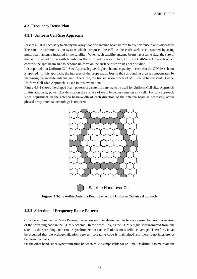
ARIB TR-T15
53
4.3 Frequency Reuse Plan 4.3.1 Uniform Cell-Size Approach First of all, it is necessary to clarify the array shape of antenna beam before frequency reuse plan is discussed. The satellite communication system which composes the cell on the earth surface is assumed by using multi-beam antenna installed in the satellite. When each satellite antenna beam has a same size, the size of the cell projected to the earth broaden in the surrounding area. Then, Uniform Cell-Size Approach which controls the spot beam size to become uniform on the surface of earth has been studied. It is reported that Uniform Cell-Size Approach gives higher channel capacity in case that the CDMA scheme is applied. In this approach, the increase of the propagation loss in the surrounding area is compensated by increasing the satellite antenna gain. Therefore, the transmission power of MES could be constant. Hence, Uniform Cell-Size Approach is used in this evaluation. Figure 4.3-1 shows the shaped beam pattern of a satellite antenna to be used for Uniform Cell-Size Approach. In this approach, power flux density on the surface of earth becomes same on any cell. For this approach, since adjustment on the antenna beam-width of each direction of the antenna beam is necessary, active phased array antenna technology is required.
4.3.2 Selection of Frequency Reuse Pattern Considering Frequency Reuse Pattern, it is necessary to evaluate the interference caused by cross correlation of the spreading code in the CDMA scheme. In the down-link, as the CDMA signal is transmitted from one satellite, the spreading code can be synchronized in each cell of a same satellite coverage. Therefore, it can be assumed that the orthogonalization between spreading code is maintained and there is no interference between channels. On the other hand, since synchronization between MES is impossible for up-link, it is difficult to maintain the
: Satellite Hand-over Cell
FIG .4.3.1 Satellite Antenna BeamPattern by Uniform Cell-Size Approach
Figure 4.3-1 Satellite Antenna Beam Pattern by Uniform Cell-size Approach
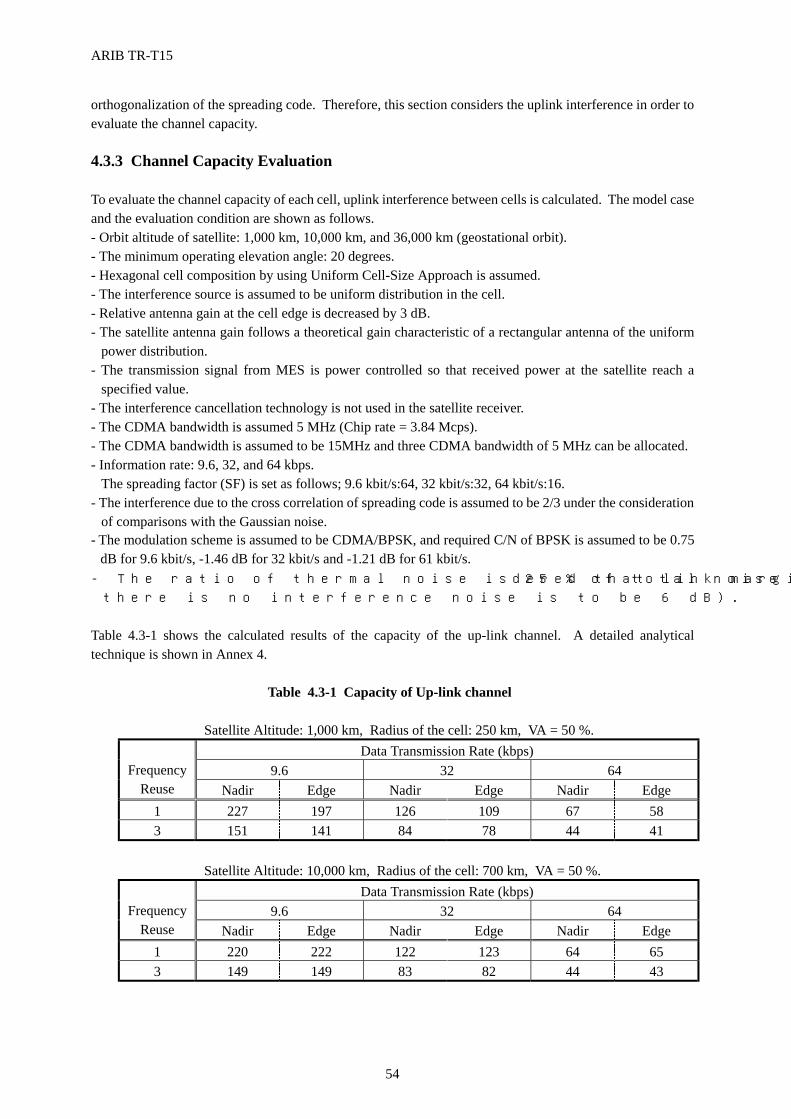
ARIB TR-T15
54
orthogonalization of the spreading code. Therefore, this section considers the uplink interference in order to evaluate the channel capacity. 4.3.3 Channel Capacity Evaluation To evaluate the channel capacity of each cell, uplink interference between cells is calculated. The model case and the evaluation condition are shown as follows. - Orbit altitude of satellite: 1,000 km, 10,000 km, and 36,000 km (geostational orbit). - The minimum operating elevation angle: 20 degrees. - Hexagonal cell composition by using Uniform Cell-Size Approach is assumed. - The interference source is assumed to be uniform distribution in the cell. - Relative antenna gain at the cell edge is decreased by 3 dB. - The satellite antenna gain follows a theoretical gain characteristic of a rectangular antenna of the uniform
power distribution. - The transmission signal from MES is power controlled so that received power at the satellite reach a
specified value. - The interference cancellation technology is not used in the satellite receiver. - The CDMA bandwidth is assumed 5 MHz (Chip rate = 3.84 Mcps). - The CDMA bandwidth is assumed to be 15MHz and three CDMA bandwidth of 5 MHz can be allocated. - Information rate: 9.6, 32, and 64 kbps.
The spreading factor (SF) is set as follows; 9.6 kbit/s:64, 32 kbit/s:32, 64 kbit/s:16. - The interference due to the cross correlation of spreading code is assumed to be 2/3 under the consideration
of comparisons with the Gaussian noise. - The modulation scheme is assumed to be CDMA/BPSK, and required C/N of BPSK is assumed to be 0.75
dB for 9.6 kbit/s, -1.46 dB for 32 kbit/s and -1.21 dB for 61 kbit/s. - The ratio of thermal noise is 25 % of total noise (It is considered that link margin when
there is no interference noise is to be 6 dB). Table 4.3-1 shows the calculated results of the capacity of the up-link channel. A detailed analytical technique is shown in Annex 4.
Table 4.3-1 Capacity of Up-link channel
Satellite Altitude: 1,000 km, Radius of the cell: 250 km, VA = 50 %. Data Transmission Rate (kbps)
9.6 32 64
Frequency Reuse Nadir Edge Nadir Edge Nadir Edge
1 227 197 126 109 67 58 3 151 141 84 78 44 41
Satellite Altitude: 10,000 km, Radius of the cell: 700 km, VA = 50 %.
Data Transmission Rate (kbps) 9.6 32 64
Frequency
Reuse Nadir Edge Nadir Edge Nadir Edge 1 220 222 122 123 64 65 3 149 149 83 82 44 43
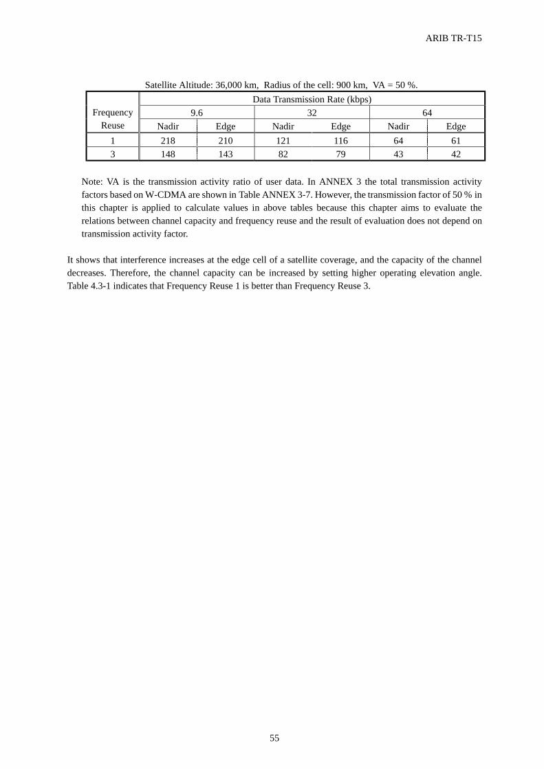
ARIB TR-T15
55
Satellite Altitude: 36,000 km, Radius of the cell: 900 km, VA = 50 %.
Data Transmission Rate (kbps) 9.6 32 64
Frequency
Reuse Nadir Edge Nadir Edge Nadir Edge 1 218 210 121 116 64 61 3 148 143 82 79 43 42
Note: VA is the transmission activity ratio of user data. In ANNEX 3 the total transmission activity factors based on W-CDMA are shown in Table ANNEX 3-7. However, the transmission factor of 50 % in this chapter is applied to calculate values in above tables because this chapter aims to evaluate the relations between channel capacity and frequency reuse and the result of evaluation does not depend on transmission activity factor.
It shows that interference increases at the edge cell of a satellite coverage, and the capacity of the channel decreases. Therefore, the channel capacity can be increased by setting higher operating elevation angle. Table 4.3-1 indicates that Frequency Reuse 1 is better than Frequency Reuse 3.
ARIB TR-T15
56
4.4 Consideration of Orbit and Satellite Constellation 4.4.1 Type of MSS Several issues such as the delay time of MSS, the handover mechanism, the realization of roaming and the coverage range of the satellite’s spot beam depend on the satellite constellations. There are two MSS types, one consists of NGSO satellites and the other is GSO satellites. The selection of the satellite orbit depends on the concept of service provision and the type of MSS is the MSS operator’s decision.
4.4.1.1 GSO Since the cell of GSO MSS is the fixed zone, the service area by GSO MSS is limited to one regional area, and the GSO MSS will be the regional based system. If the regional service is only provided by the GSO MSS, it is possible to realize the GSO MSS using of a few satellites. In addition to this, it is easy to make the system configuration for GSO MSS because the zone configuration is very simple and the handover probability on the GSO MSS is low. However, the delay time of GSO MSS is long. Also, when the cell of GSO MSS is changed to a smaller size, the LEO’s satellite antenna size will be much larger. Therefore, there is the limitation of cell size in making a smaller cell because of the practical antenna size of the GSO MSS. 4.4.1.2 NGSO In the case of NGSO MSS, the support of handover is essential as described in section 2.5.2.1 but the handover mechanism is complicated due to the fast movement of the LEO satellite. In order to cover the surface of earth for world-wide, the cell’s zone configuration based on the LEO constellation’s type requires the transmission control for each cell of the overlapped beam area is seemed to be complicated. The delay time of the LEO MSS can be small enough as compared with the IMT-2000 terrestrial’s MS systems. The spot beam size depends on the altitude of a satellite. In the case of the LEO satellite it is possible to have a small cell which is nearly close to the cell size of cellular’s. Therefore, the small cell size can be applied to the high traffic area.
There are two NGSO Constellation types and the general descriptions are on following sections.
4.4.2 Description of Satellite Topologies for NGSO 4.4.2.1 Two types of Constellations (π-constellation and 2π-constellation) The satellite constellation is classified into two topologies for the low-earth-orbit satellite communication system which globally covers the surface of earth. One is π-constellation and the other is 2π-constellation. Figure 4.4-1 show π-constellation. In this case, the orbital planes are allocated with equal intervals in the range of 180 degrees on the equator. π-constellation has a feature that the number of satellites are concentrated in a polar region . The number of satellites to be required for MSS can be minimized in order to cover the earth surface completely. There are two seams on the orbital plane where the satellite of the adjacent orbital plane moves backward at intervals of latitude 180 degrees and the communication between satellites is impossible through the seams. Figure 4.4-2 show 2π-constellation. In this case, the orbital planes are allocated with equal intervals in the range of 360 degrees on the equator. Also, this case uses the inclined orbit instead of a polar orbit. 2π-constellation has a feature that the region of medium latitude where the population density is high can be efficiently covered. Also, since there is no seam on the orbital planes, the communication network design can be simplified. There are two satellite group, one group moves to the northeast direction, the other group moves to the southeast direction. The two satellite group cover the same region simultaneously. Therefore,
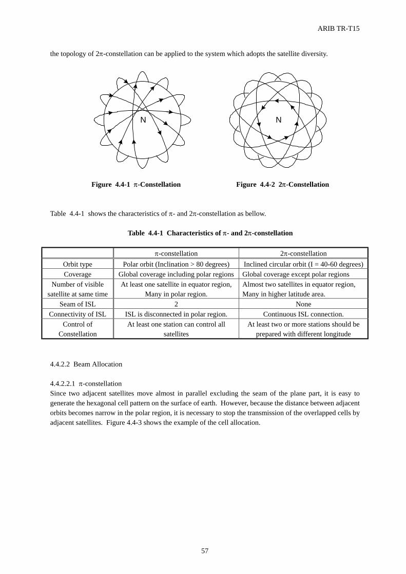
ARIB TR-T15
57
the topology of 2π-constellation can be applied to the system which adopts the satellite diversity.
Figure 4.4-1 π-Constellation Figure 4.4-2 2π-Constellation
Table 4.4-1 shows the characteristics of π- and 2π-constellation as bellow.
Table 4.4-1 Characteristics of π- and 2π-constellation
π-constellation 2π-constellation Orbit type Polar orbit (Inclination > 80 degrees) Inclined circular orbit (I = 40-60 degrees) Coverage Global coverage including polar regions Global coverage except polar regions
Number of visible satellite at same time
At least one satellite in equator region, Many in polar region.
Almost two satellites in equator region, Many in higher latitude area.
Seam of ISL 2 None Connectivity of ISL ISL is disconnected in polar region. Continuous ISL connection.
Control of Constellation
At least one station can control all satellites
At least two or more stations should be prepared with different longitude
4.4.2.2 Beam Allocation 4.4.2.2.1 π-constellation Since two adjacent satellites move almost in parallel excluding the seam of the plane part, it is easy to generate the hexagonal cell pattern on the surface of earth. However, because the distance between adjacent orbits becomes narrow in the polar region, it is necessary to stop the transmission of the overlapped cells by adjacent satellites. Figure 4.4-3 shows the example of the cell allocation.
NN
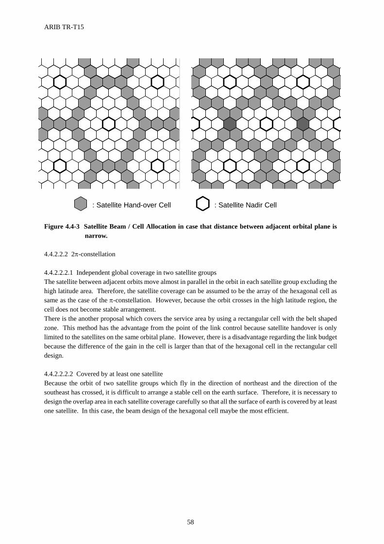
ARIB TR-T15
58
Figure 4.4-3 Satellite Beam / Cell Allocation in case that distance between adjacent orbital plane is
narrow. 4.4.2.2.2 2π-constellation 4.4.2.2.2.1 Independent global coverage in two satellite groups The satellite between adjacent orbits move almost in parallel in the orbit in each satellite group excluding the high latitude area. Therefore, the satellite coverage can be assumed to be the array of the hexagonal cell as same as the case of the π-constellation. However, because the orbit crosses in the high latitude region, the cell does not become stable arrangement. There is the another proposal which covers the service area by using a rectangular cell with the belt shaped zone. This method has the advantage from the point of the link control because satellite handover is only limited to the satellites on the same orbital plane. However, there is a disadvantage regarding the link budget because the difference of the gain in the cell is larger than that of the hexagonal cell in the rectangular cell design. 4.4.2.2.2.2 Covered by at least one satellite Because the orbit of two satellite groups which fly in the direction of northeast and the direction of the southeast has crossed, it is difficult to arrange a stable cell on the earth surface. Therefore, it is necessary to design the overlap area in each satellite coverage carefully so that all the surface of earth is covered by at least one satellite. In this case, the beam design of the hexagonal cell maybe the most efficient.
: Satellite Hand-over Cell : Satellite Nadir Cell
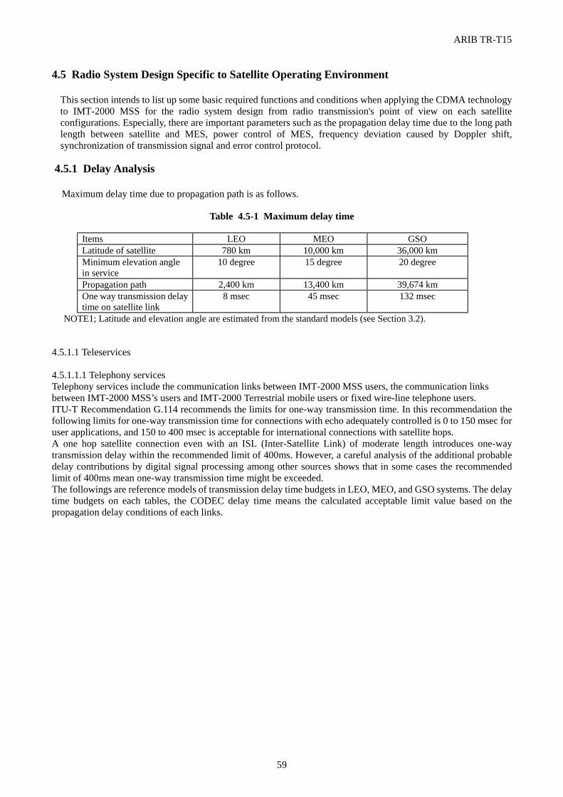
ARIB TR-T15
59
4.5 Radio System Design Specific to Satellite Operating Environment
This section intends to list up some basic required functions and conditions when applying the CDMA technology to IMT-2000 MSS for the radio system design from radio transmission's point of view on each satellite configurations. Especially, there are important parameters such as the propagation delay time due to the long path length between satellite and MES, power control of MES, frequency deviation caused by Doppler shift, synchronization of transmission signal and error control protocol.
4.5.1 Delay Analysis Maximum delay time due to propagation path is as follows.
Table 4.5-1 Maximum delay time
Items LEO MEO GSO Latitude of satellite 780 km 10,000 km 36,000 km Minimum elevation angle in service
10 degree 15 degree 20 degree
Propagation path 2,400 km 13,400 km 39,674 km One way transmission delay time on satellite link
8 msec 45 msec 132 msec
NOTE1; Latitude and elevation angle are estimated from the standard models (see Section 3.2). 4.5.1.1 Teleservices 4.5.1.1.1 Telephony services Telephony services include the communication links between IMT-2000 MSS users, the communication links between IMT-2000 MSS’s users and IMT-2000 Terrestrial mobile users or fixed wire-line telephone users. ITU-T Recommendation G.114 recommends the limits for one-way transmission time. In this recommendation the following limits for one-way transmission time for connections with echo adequately controlled is 0 to 150 msec for user applications, and 150 to 400 msec is acceptable for international connections with satellite hops. A one hop satellite connection even with an ISL (Inter-Satellite Link) of moderate length introduces one-way transmission delay within the recommended limit of 400ms. However, a careful analysis of the additional probable delay contributions by digital signal processing among other sources shows that in some cases the recommended limit of 400ms mean one-way transmission time might be exceeded. The followings are reference models of transmission delay time budgets in LEO, MEO, and GSO systems. The delay time budgets on each tables, the CODEC delay time means the calculated acceptable limit value based on the propagation delay conditions of each links.
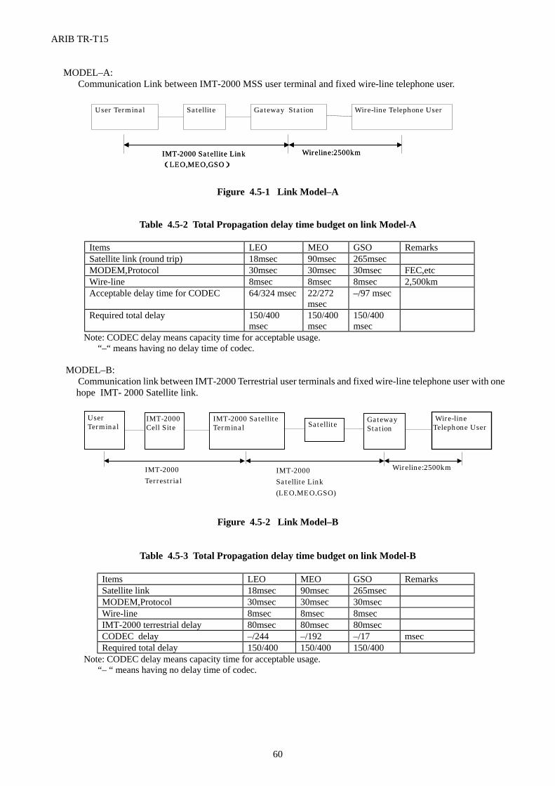
ARIB TR-T15
60
MODEL–A: Communication Link between IMT-2000 MSS user terminal and fixed wire-line telephone user.
Figure 4.5-1 Link Model–A
Table 4.5-2 Total Propagation delay time budget on link Model-A
Items LEO MEO GSO Remarks Satellite link (round trip) 18msec 90msec 265msec MODEM,Protocol 30msec 30msec 30msec FEC,etc Wire-line 8msec 8msec 8msec 2,500km Acceptable delay time for CODEC 64/324 msec 22/272
msec –/97 msec
Required total delay 150/400 msec
150/400 msec
150/400 msec
Note: CODEC delay means capacity time for acceptable usage. “–“ means having no delay time of codec. MODEL–B: Communication link between IMT-2000 Terrestrial user terminals and fixed wire-line telephone user with one
hope IMT- 2000 Satellite link.
Figure 4.5-2 Link Model–B
Table 4.5-3 Total Propagation delay time budget on link Model-B
Items LEO MEO GSO Remarks Satellite link 18msec 90msec 265msec MODEM,Protocol 30msec 30msec 30msec Wire-line 8msec 8msec 8msec IMT-2000 terrestrial delay 80msec 80msec 80msec CODEC delay –/244 –/192 –/17 msec Required total delay 150/400 150/400 150/400
Note: CODEC delay means capacity time for acceptable usage. “– “ means having no delay time of codec.
User Terminal Satellite Gateway Station Wire-line Telephone User
IMT-2000 Satellite Link (LEO,MEO,GSO) IMT-2000 Satellite Link (LEO,MEO,GSO)
Wireline:2500km Wireline:2500km
Wire-line Telephone User
Gateway Station Satellite IMT-2000 Satellite
Terminal IMT-2000 Cell Site
User Terminal
IMT-2000 Terrestrial
IMT-2000 Satellite Link (LEO,MEO,GSO)
Wireline:2500km
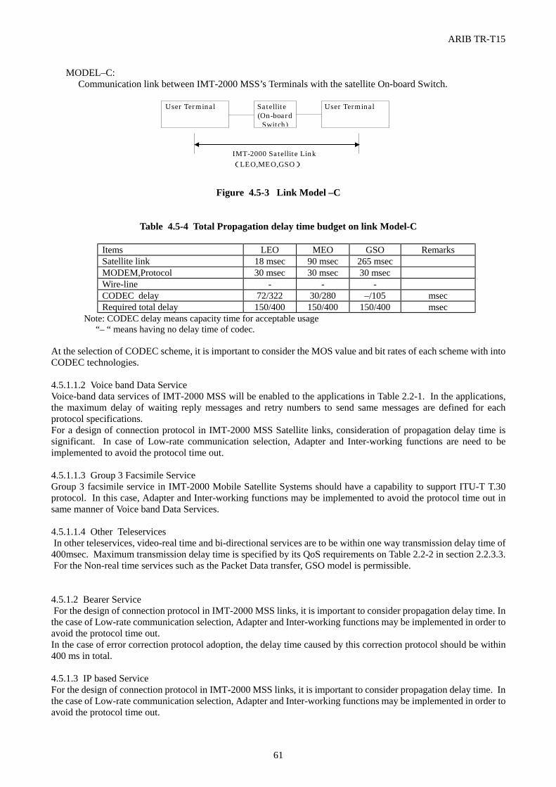
ARIB TR-T15
61
MODEL–C: Communication link between IMT-2000 MSS’s Terminals with the satellite On-board Switch.
Figure 4.5-3 Link Model –C
Table 4.5-4 Total Propagation delay time budget on link Model-C
Items LEO MEO GSO Remarks Satellite link 18 msec 90 msec 265 msec MODEM,Protocol 30 msec 30 msec 30 msec Wire-line - - - CODEC delay 72/322 30/280 –/105 msec Required total delay 150/400 150/400 150/400 msec
Note: CODEC delay means capacity time for acceptable usage “– “ means having no delay time of codec. At the selection of CODEC scheme, it is important to consider the MOS value and bit rates of each scheme with into CODEC technologies. 4.5.1.1.2 Voice band Data Service Voice-band data services of IMT-2000 MSS will be enabled to the applications in Table 2.2-1. In the applications, the maximum delay of waiting reply messages and retry numbers to send same messages are defined for each protocol specifications. For a design of connection protocol in IMT-2000 MSS Satellite links, consideration of propagation delay time is significant. In case of Low-rate communication selection, Adapter and Inter-working functions are need to be implemented to avoid the protocol time out. 4.5.1.1.3 Group 3 Facsimile Service Group 3 facsimile service in IMT-2000 Mobile Satellite Systems should have a capability to support ITU-T T.30 protocol. In this case, Adapter and Inter-working functions may be implemented to avoid the protocol time out in same manner of Voice band Data Services. 4.5.1.1.4 Other Teleservices In other teleservices, video-real time and bi-directional services are to be within one way transmission delay time of 400msec. Maximum transmission delay time is specified by its QoS requirements on Table 2.2-2 in section 2.2.3.3. For the Non-real time services such as the Packet Data transfer, GSO model is permissible. 4.5.1.2 Bearer Service For the design of connection protocol in IMT-2000 MSS links, it is important to consider propagation delay time. In the case of Low-rate communication selection, Adapter and Inter-working functions may be implemented in order to avoid the protocol time out. In the case of error correction protocol adoption, the delay time caused by this correction protocol should be within 400 ms in total. 4.5.1.3 IP based Service For the design of connection protocol in IMT-2000 MSS links, it is important to consider propagation delay time. In the case of Low-rate communication selection, Adapter and Inter-working functions may be implemented in order to avoid the protocol time out.
User Terminal Satellite (On-board
Switch)
User Terminal
IMT-2000 Satellite Link (LEO,MEO,GSO)
ARIB TR-T15
62
In the case of error correction protocol adoption, the delay time caused by this protocol should be within 400 ms in total. Maximum transmission delay time is specified by its QoS requirements on Table 2.2-2 in section 2.2.3.3. 4.5.2 Power Control Technologies to compress ambiguities and deviations of user terminal’s transmission power are required in CDMA scheme. Especially, in IMT-2000 MSS links, deviations of path length in satellites propagation and fading depth should be considered. 4.5.2.1 Required Range of Transmission Power Control Control range of transmission power depends on deviation of propagation path length and fading depth. Deviation of propagation length with each case of satellite constellations is shown on Table 4.5-5. Fading depth is mostly defined by carrier frequency, a channel bandwidth and elevation angles in a line of sight to the satellite. The amplitude distribution of fading is assumed to be within -12dB from Table 3.4-2 in section 3.4.4. Table 4.5-5 shows an example of the estimated range of transmission power control. In LEO systems, the variation of propagation loss seems to be compensated by adapting of Uniform cell-size technique to compress within 2dB of SFD.
Table 4.5-5 Estimated Range of Transmission Power Control Items LEO MEO GSO minimum path length 780km 10,000km 36,000km maximum path length 2,400km 13,400km 39,674km SFD deviation 9.6dB 2.5dB 0.8dB Fading amplitude deviation 12.1dB 12.1dB 12.1dB Margin 3dB 3dB 3dB Total deviation to be controlled 15.1dB 17.5dB 15.9dB Note ; Margin is assumed to have deviation in an area of a satellite beam and terminals antenna pattern. 4.5.2.2 Transmission Power Control Error Transmission power control (TPC) error bring to the degradation of C/I in CDMA directly. As TPC error is larger, the interference on the CDMA system is larger and the channel capacity is less. The TPC error is caused by the delay of closed loop and deviation of the transmission power. In IMT-2000 MSS, since the delay is longer than the fading pitch, open loop control technologies are needed in addition of closed loop. The fading pitch is defined from the mobility speed of an user terminal/the satellite and the elevation angle of the satellite. The deviation of the transmission power in the user terminal includes atmospheric compensation errors of power amplifier devices and power detectors. This error is small relatively to that error caused by delayed loop, so it can be kept within ±1dB. Considering the elevation angles of each satellite constellation, the delay in the closed loop control should be at least smaller than 25% of the pitch cycle time. As mentioned above, the open loop control technique or the averaging control technique is needed for TPC in IMT-2000 MSS.
ARIB TR-T15
63
4.5.3 Compensation of Frequency Deviation Caused by Doppler Shift The Doppler shifts occurred due to the velocity change caused by the movement of a satellite relative to the user terminal, and the Doppler shifts causes the clock timing and frequency shifts of the carrier from the satellite. The deviation value of the Doppler shift is changed by the velocity value based on the Satellite orbital altitude and relative to user terminal's velocity. Appendix to section 3.4.3 shows the equation to calculate the Doppler shift's value. In section 3.3, there is the description of the maximum Doppler shift value. Since the frequency shift due to the Doppler shift causes sync-loss or bit error, receivers and satellite systems need to compensation mechanism the Doppler shift. 4.5.3.1 Doppler Shift Buffer for Clock Timing Receivers need a buffer in order to compensate the clock shift caused by the Doppler shifts. When connecting to the Public Land Networks from the satellite link, re-sampling by network-master clock is needed. 4.5.3.2 Phase lock for Carrier Recovery In Doppler rate shift caused by LEO and MEO systems, carrier recovery circuits should be designed to pursue frequency shift. There are needs to have techniques to pre-equalize shifts or to construct PLL 3rd loop applied to carrier recovery. 4.5.3.3 Estimate Doppler shifts from Satellite orbit In the case of satellite handover, the carrier frequency hop is caused by the difference of the satellites velocities. The carrier frequency hop affects sync-loss of receivers at user terminals of IMT-2000 MSS. To equalize the frequency shifts, detecting beam ID and satellite ID number are useful to estimate the frequency shifts. On the other hand, compensation mechanism of the frequency shifts are required at satellite transmission system and/or Land Earth Station transmission system. 4.5.4 Synchronization IMT-2000 MSS includes any case of synchronization between channels, adjacent cells within a same satellite and adjacent cells of adjacent satellites. In the operational procedures applied to IMT-2000 MSS, there are several problems in the protocols due to the propagation delay. 4.5.4.1 Channel Synchronization In return links, transmission timing of user terminals should be controlled to synchronize spread code chip timing via a satellite. Therefore, equalizing techniques for deviation of a propagation delay and frequency shifts are required in the precise chip timing. And in order to keep the orthogonal condition between channels, the synchronization of chip timing is needed to keep synchronization between channels, adjacent cells of a same satellite, adjacent cells of adjacent satellites (Non GSOs). On the other hand, maximum power densities of all access terminals should not interfere to other systems. 4.5.4.2 Cell Synchronization In IMT-2000 MSS systems, the cell synchronization between adjacent cells of a same satellite is achieved easily so that beams of each cell are transmitted from the same satellite in the forward link. The long-codes for spreading carriers are used to individualize beams. Regarding the synchronization method, since the long-code should be common in each cells, it is necessary to consider other way to individualize beams. In the return link the synchronization of access timing are required as the same as mentioned above.
ARIB TR-T15
64
4.5.4.3 Adjacent Satellite Synchronization In cases of LEO and MEO in IMT-2000 MSS systems, a MES needs to change the accessing satellite with handover between adjacent cells of adjacent satellites in keeping of synchronization. The most significant technique to achieve the synchronization during the handover is to make a hand-off sequence completely by keeping the access timing with the closed loop. 4.5.4.4 Synchronization Procedures To synchronize physical channels between forwardlink and returnlink , procedures must consider propagation delay time of satellites links. The delay time causes time-out error and retry-out error. MES and LES should wait for accepting reply messages. And the interval time of sending retry messages should be longer than the delay time.
4.5.5 Consideration of Low Layer Protocol Specific to Satellite Environment The following items should be considered when designing low layer protocol of the link between User Terminal and Satellite.
(1) Wait Timer should cover propagation delay time. (2) Reply Check should be done after performed Wait Timer (3) For the sequence on low layer protocol to be selected, low BER, transmission retry process or word error margin
should be required. (4) The selection of CODEC for telephony services should be decided based on the conditions of Satellite orbits and
processing delay time of the CODEC. (5) Physical channel frame structure should be designed carefully under the conditions such as Doppler shift and fading
pitch cycle.
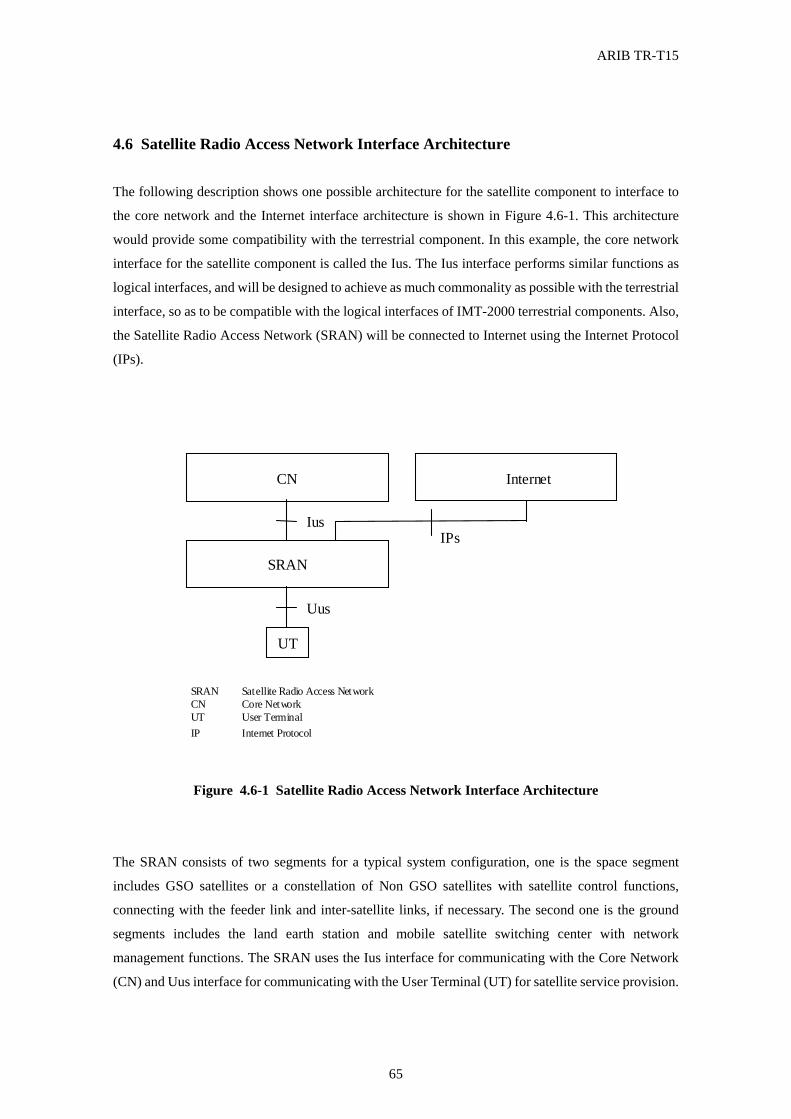
ARIB TR-T15
65
4.6 Satellite Radio Access Network Interface Architecture The following description shows one possible architecture for the satellite component to interface to
the core network and the Internet interface architecture is shown in Figure 4.6-1. This architecture
would provide some compatibility with the terrestrial component. In this example, the core network
interface for the satellite component is called the Ius. The Ius interface performs similar functions as
logical interfaces, and will be designed to achieve as much commonality as possible with the terrestrial
interface, so as to be compatible with the logical interfaces of IMT-2000 terrestrial components. Also,
the Satellite Radio Access Network (SRAN) will be connected to Internet using the Internet Protocol
(IPs).
SRAN
UT
Uus
SRAN
Satellite Radio Access Network CN
Core Network UT User Terminal
CN
Ius
Internet
IPs
IP Internet Protocol
Figure 4.6-1 Satellite Radio Access Network Interface Architecture
The SRAN consists of two segments for a typical system configuration, one is the space segment
includes GSO satellites or a constellation of Non GSO satellites with satellite control functions,
connecting with the feeder link and inter-satellite links, if necessary. The second one is the ground
segments includes the land earth station and mobile satellite switching center with network
management functions. The SRAN uses the Ius interface for communicating with the Core Network
(CN) and Uus interface for communicating with the User Terminal (UT) for satellite service provision.
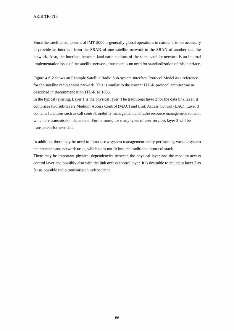
ARIB TR-T15
66
Since the satellite component of IMT-2000 is generally global operations in nature, it is not necessary
to provide an interface from the SRAN of one satellite network to the SRAN of another satellite
network. Also, the interface between land earth stations of the same satellite network is an internal
implementation issue of the satellite network, thus there is no need for standardization of this interface.
Figure 4.6-2 shows an Example Satellite Radio Sub-system Interface Protocol Model as a reference
for the satellite radio access network. This is similar to the current ITU-R protocol architecture as
described in Recommendation ITU-R M.1035.
In the typical layering, Layer 1 is the physical layer. The traditional layer 2 for the data link layer, it
comprises two sub-layers Medium Access Control (MAC) and Link Access Control (LAC). Layer 3
contains functions such as call control, mobility management and radio resource management some of
which are transmission dependent. Furthermore, for many types of user services layer 3 will be
transparent for user data.
In addition, there may be need to introduce a system management entity performing various system
maintenance and network tasks, which does not fit into the traditional protocol stack.
There may be important physical dependencies between the physical layer and the medium access
control layer and possibly also with the link access control layer. It is desirable to maintain layer 3 as
far as possible radio transmission independent.
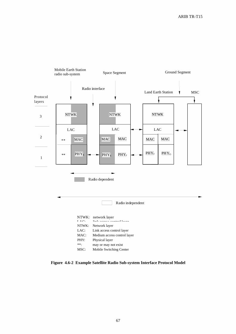
ARIB TR-T15
67
Figure 4.6-2 Example Satellite Radio Sub-system Interface Protocol Model
Protocollayers
3
2
1
Mobile Earth Stationradio sub-system
Radio interface
NTWK NTWK
LAC LAC
MAC
PHYS PHY**
**
Radio dependent
Radio independent
Space Segment Ground Segment
MAC
PHYFPHYS
NTWK
LAC
MAC
PHYGPHYF
MAC
Land Earth Station MSC
MAC
NTWK:LAC:MAC:
network layerlink access control layermedium access control layer
PHY:**:
physical layermay or may not exist
MSC: Mobile Switching CenterNTWK: Network layer LAC: Link access control layer MAC: Medium access control layer PHY: Physical layer **: may or may not exist MSC: Mobile Switching Center
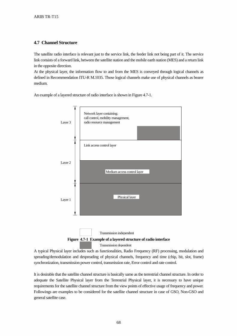
ARIB TR-T15
68
4.7 Channel Structure The satellite radio interface is relevant just to the service link, the feeder link not being part of it. The service link consists of a forward link, between the satellite station and the mobile earth station (MES) and a return link in the opposite direction. At the physical layer, the information flow to and from the MES is conveyed through logical channels as defined in Recommendation ITU-R M.1035. Those logical channels make use of physical channels as bearer medium. An example of a layered structure of radio interface is shown in Figure 4.7-1.
Figure 4.7-1 Example of a layered structure of radio interface
A typical Physical layer includes such as functionalities, Radio Frequency (RF) processing, modulation and spreading/demodulation and despreading of physical channels, frequency and time (chip, bit, slot, frame) synchronization, transmission power control, transmission rate, Error control and rate control. It is desirable that the satellite channel structure is basically same as the terrestrial channel structure. In order to adequate the Satellite Physical layer from the Terrestrial Physical layer, it is necessary to have unique requirements for the satellite channel structure from the view points of effective usage of frequency and power. Followings are examples to be considered for the satellite channel structure in case of GSO, Non-GSO and general satellite case.
Network layer containing: call control, mobility management, radio resource management
Link access control layer
Medium access control layer
Physical layer Layer 1
Layer 2
Layer 3
Transmission independent
Transmission dependent
ARIB TR-T15
69
(a) Low bit rate
Low bit rate circuits will be use mainly in MT-2000 MSS and this low bit rate causes large over head percentage on transmission and inefficient transmission. Therefore, Physical Channel needs to be considered to have a capability of the mode which can select a longer frame greater than 10 ms frame length.
(b) Propagation Delay
When designing the satellite radio interface to a satellite which has long delay time (see section 4.5.1 Delay Analysis), the propagation delay for each satellite system should be considered, especially on packet data transmission.
Delayed control signals to respond
For instance, the repeating method on a random-access protocol is not appropriate for the access with a satellite.
Increasing of the closed loop of TPC error
For instance, effective of open-loop control is expected. Increasing of absolute delay time of signal transmission
The long round trip transmission delays associated to satellite links do not permit fast acting closed loop power control (approximately max. 25 ms in the assumed LEO system and approximately 200 ms for the MEO system). For a LEO system, it would be sufficient to transmit one power control command per frame (every 20 ms). For high data rate transmissions where more than one burst is transmitted per frame, transmission of TPC in each burst might be an overkill.
(c) One transmission point
Transmission point is only one site even if a constellation of satellites is used, the transmission sites are limited.
Easy to use the common pilot signal
For instance, it will be easy to use absolute time synchronization.
(d) Limited transmission power and frequency bandwidth Since a satellite power is limited, it should be considered that a large link margin and a poor power
control cause an unexpected low channel capability. Therefore, the closed loop power control on the forward and return link should be considered in order to partly compensate link loss variations to individual Mobile Terminals(MTs) reducing interference resulting from excess link margins. The closed loop power control may be applied to all dedicated physical channels of a two-way stream mode transmission, but not to common physical channels and to infrequent packet data transfer without dedicated channel assignment. This has to be considered if the common pilot channel is used to assist demodulation of a power controlled dedicated physical channel. Sufficient link margins have to be provided for the common pilot channel. As the result, power and spectral efficiency are improved if it is possible to have reduction of overhead due to the use of a common pilot/beam cluster approach.
ARIB TR-T15
70
Satellite signalling and broadcast channels should be considered to operate at higher powers or with
more robust protection than traffic channels. The minimum spectrum requirement of the proposed W-CDMA system is two times 5 MHz. A
100% re-use of the carrier frequencies within a satellite of a single SRAN is envisaged. Satellite spectrum will be very scarce compared to terrestrial spectrum (where micro cellular networks can be used, for example, to increase capacity). All channel overheads will need to be reduced to an absolute minimum. Some functions that might be handled in higher terrestrial layers could, for example, be embodied more efficiently within the satellite physical layer.
(e) Antenna pattern
To support of satellite adaptive antennas in the forward link, the power and spectral efficiency can be obtained.
Beam-to-beam soft handover may or may not to be possible because the propagation model between MES and satellite will be free space loss, which is big different from the terrestrial propagation model with 4th power of the attenuation.
(f) Signal strength fluctuations are remarkably lower for satellite links (Rician fading) than they are for
terrestrial links (Rayleigh fading). It seems that open loop power control could be useful to compensate for slight shadowing as caused
by trees but not always to mitigate multipath fading. A bounce path off the ground may produce an echo with a relative delay in the range of 2 to 10 ns, assuming a terminal antenna 1.5 m above ground and a minimum elevation angle of 10 degrees. The corresponding fading decorrelation frequency spacing would be in the range of 50 to 250 MHz. Assuming a duplex spacing of 190 MHz, sufficient fading correlation between forward and return link cannot always be guaranteed. Since it is not possible to differentiate between multipath fading and shadowing (at least not for stationary MT's), relying on open loop power control seems to be insufficient.
The shadowing caused by buildings etc. poses problems for both terrestrial and satellite components.
It may be countered by several techniques such as link margin, coding, etc.
(g) Means should be provided to compensate for the Doppler frequency shift due to the satellite movement in both feeder and service links. It is proposed to maintain time synchronism between all satellites belonging to the same SRAN.
This means transmissions from different satellites are aligned to one another with respect to the frame structure within an accuracy in the order of a ms. In case of transparent payloads and no inter-satellite links, the system-wide synchronization may be maintained by the Land Earth Stations interconnected via a terrestrial network. Time alignment limits frame timing differences between pairs of satellites to the minimum possible.
Radio access techniques must be tolerant of signal acquisition delays, variable propagation delays,
Doppler shifts, and delay or Doppler jumps.

ARIB TR-T15
71
4.8 Multiple Access Scheme 4.8.1 Multi-channel Access Operation
The code division multiple access (CDMA) technique with RF channel bandwidth of 5 MHz for each
transmission direction is considered to be applicable for IMT-2000 MSS as the first phase.
IMT-2000 MSS is available for CDMA systems based on W-CDMA whose chip rate is 3.84
Mcps and MC-CDMA whose chip rate is 3.68 Mcps.
4.8.2 Duplex Operation (FDD and TDD Mode Operation)
The CDMA air interface can be applicable to operate in either FDD mode or TDD mode. The
possibility to operate in either FDD or TDD mode allows for efficient utilization of the available
spectrum according to the frequency allocation in different regions.
These modes are as follows:
FDD : A duplex method whereby forward link and reverse link transmissions use two separated radio
frequency. In the FDD, each forward and reverse link uses the different frequency band. A
pair of frequency band which has specified separation shall be assigned for the system.
TDD : A duplex method whereby forward link and reverse link transmissions are carried over same
radio frequency by using synchronized time intervals. In the TDD, time slots in a physical
channel are divided into transmission and reception part. Information on forward link and
reverse link are transmitted reciprocally.
When MSS operates in an FDD mode to provide the worldwide services, it should be considered that
there is not generally a fixed frequency relationship between the Earth-to-space and space-to-Earth
frequencies used for communications to and from the MESs because of the differences of IMT-2000
MSS spectrum allocation in each region.
In order to use an TDD mode for IMT-2000 MSS, it is required to determine guard time and switching
timing for transmission and receive under the consideration of Doppler shift. When the propagation
delay time is long, guard time will be long and the frequency efficiency is extremely decreased.
Therefore, the usage of TDD mode is practically limited to be used for LEO MSS.
ARIB TR-T15
72
4.8.3 Packet Data Access
In packet data transmission using dedicated physical channels, Reverse-link and forward-link
dedicated physical channels are always handled as a pair.
In order to make good use of radio resources and facilities resources without service quality
degradation, it is necessary to switchover physical channel (logical channel) on demand adapted to
transmission characteristic such as packet data traffic, every moment.
Without an acknowledge of the received packet data and re-transmission in error conditions when the
propagation delay is long, the throughputs of packet data transmission is degraded. Therefore, it is
essential to use error correction control with the consideration of transmission delay and bit error rate.
ARIB TR-T15
73
4.9 Modulation and Coding Schedule and technical discussion of IMT-2000 terrestrial system have been proceeding to that of IMT-2000 MSS about the system realization. To apply the modulation and coding scheme of IMT-2000 terrestrial system into IMT-2000 MSS will bring much benefits which are not only mutual transparency of information but also co-use of technologies to realize the IMT-2000 MSS. Therefore, the same modulation and coding scheme as IMT-2000 terrestrial system should be introduced to IMT-2000 MSS except any technical difficulties due to specific issues on satellite environments. 4.9.1 Coding and Interleaving Data streams from/to MAC and higher layers are encoded/decoded to offer services over the radio transmission link. The coding/multiplexing steps can be identified as follows; - Add CRC to each transport block, - Transport block concatenation and code block segmentation, - Channel coding, - Rate matching, - Insertion of discontinuous transmission indication bits, - Interleaving, - Radio frame segmentation, - Multiplexing of transport channels, - Physical channel segmentation, - Mapping to physical channels. Figure 4.9-1 is an example of the transport channel multiplexing structure in IMT-2000 terrestrial system, which gives the coding/multiplexing steps for uplink and downlink. The cyclic redundancy check (CRC) provides for error detection of the transport blocks for the particular transport channel. The types of channel coding defined are convolutional coding, turbo coding and no-coding. Real-time services use only FEC encoding while non real-time services use a combination of FEC and ARQ. The technique on coding/multiplexing scheme described above is applicable not only to IMT-2000 terrestrial system but also many wireless communication systems with some modification. To apply the IMT-2000 MSS, detailed studies should be required regarding the specific satellite issues such as large propagation delay and propagation loss. For example, it should be considered to avoid the excess degradation of throughput caused by inappropriate control of ARQ under the poor BER conditions. In addition, the effective combination of convolution code and any other algebraic code, for example Reed-Solomon code may be studied as FEC. The length of interleaving derives time delay in communication link on both IMT-2000 MSS and terrestrial system equally. However, the burst error characteristics in MSS communication link are different from terrestrial system’s one. Therefore, the degree of interleaving length should be appropriately selected to minimize total link delay and maximize throughput.
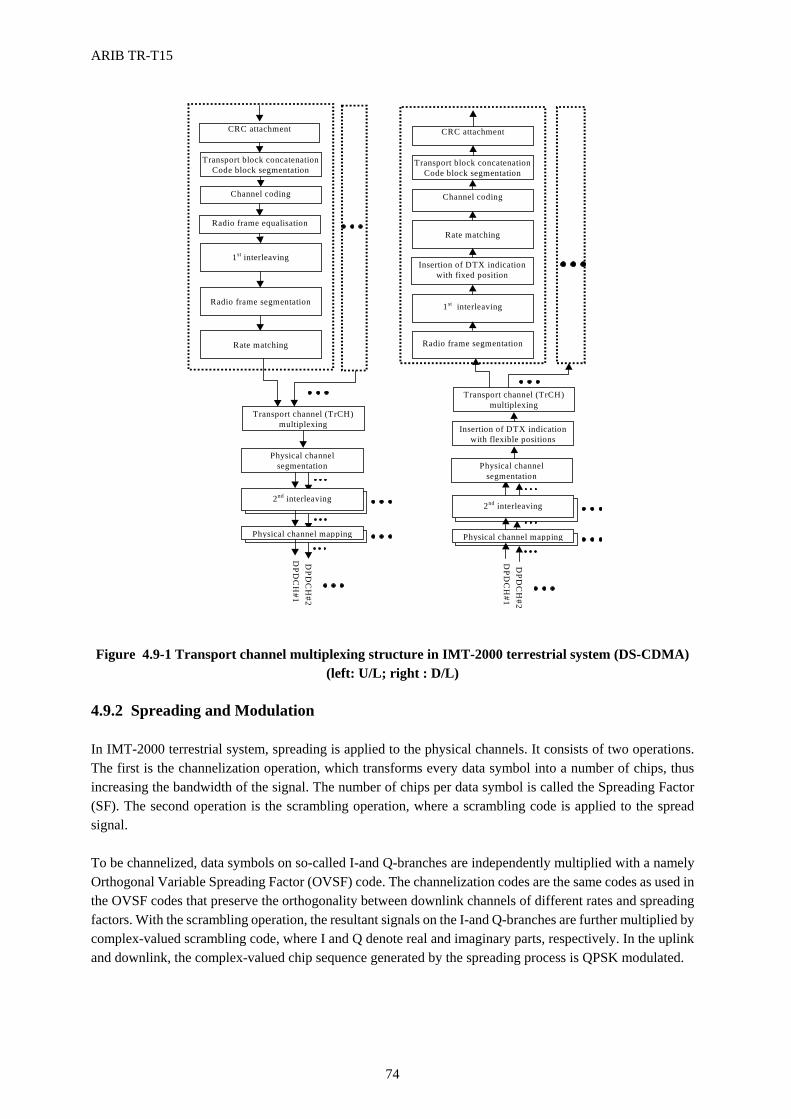
ARIB TR-T15
74
Transport block concatenationCode block segmentation
Channel coding
1st interleaving
Rate matching
CRC attachment
Physical channelsegmentation
Physical channel mapping
DPD
CH
#1D
PDC
H#2
2nd interleaving
Transport channel (TrCH)multiplexing
Radio frame segmentation
Transport block concatenationCode block segmentation
Channel coding
Rate matching
1st interleaving
Insertion of DTX indicationwith flexible positions
Physical channel mapping
DPD
CH
#1D
PDC
H#2
2nd interleaving
CRC attachment
Insertion of DTX indicationwith fixed position
Transport channel (TrCH)multiplexing
Radio frame segmentation
Radio frame equalisation
Physical channelsegmentation
Figure 4.9-1 Transport channel multiplexing structure in IMT-2000 terrestrial system (DS-CDMA)
(left: U/L; right : D/L) 4.9.2 Spreading and Modulation In IMT-2000 terrestrial system, spreading is applied to the physical channels. It consists of two operations. The first is the channelization operation, which transforms every data symbol into a number of chips, thus increasing the bandwidth of the signal. The number of chips per data symbol is called the Spreading Factor (SF). The second operation is the scrambling operation, where a scrambling code is applied to the spread signal. To be channelized, data symbols on so-called I-and Q-branches are independently multiplied with a namely Orthogonal Variable Spreading Factor (OVSF) code. The channelization codes are the same codes as used in the OVSF codes that preserve the orthogonality between downlink channels of different rates and spreading factors. With the scrambling operation, the resultant signals on the I-and Q-branches are further multiplied by complex-valued scrambling code, where I and Q denote real and imaginary parts, respectively. In the uplink and downlink, the complex-valued chip sequence generated by the spreading process is QPSK modulated.
ARIB TR-T15
75
These techniques can be applicable to IMT-2000 MSS, not distinctive for IMT-2000 terrestrial system. 4.9.3 Consideration for Coherent Detection There are two approaches to prompt bit synchronization. One is the outer pilot approach in which an individual pilot signal is always transmitted with data stream, and the other is the inner pilot approach in which a short pilot burst is inserted in each data frame. Since the outer pilot approach provides continuous pilot code, it is easy to detect bit synchronization. While the inner pilot approach can provide a capability to have bit synchronization within its own channel and asynchronous operation between channels is possible. For the MSS, since the realization of bit synchronization between each channels even on different cells is easy for the downlink direction, the both approaches can be applied to IMT-2000 MSS. In the case of uplink, due to difficulty of bit synchronization among user terminals, the inner pilot approach may be appropriate. In the case of downlink, the outer pilot approach is more suitable because it is relatively stable with small ambiguity of synchronization and short acquisition time even in low C/N condition on the satellite channel. Furthermore, it is difficult to use the synchronous CDMA based on the orthogonal spreading code. That is, the mismatching of synchronization in the uplink is increased in proportion to the cell size on the ground, and the mutual synchronization between the downlink signals from different satellites is also required in the use of during the hand-over or at the satellite diversity. 4.9.4 Consideration for Pilot Signal Power The pilot signal is necessary to have the initial acquisition, coherent detection and frame synchronization. For the outer pilot in the downlink, the usage of pilot signal as a common reference brings reliable synchronization as above functions without excess system capacity degradation. Therefore it should be desirable to emphasis the power level of pilot signal.
ARIB TR-T15
76
4.10 Multi-Satellite Scenarios 4.10.1 Interference considerations Providing global coverage, there must be zones that are covered by beams of at least two different satellites. Overlapping coverage zones are the result, if full coverage (without gaps) in an area being largest than the service area of a single satellite is to be provided at any time. Despite the fact that macro path diversity may be exploited, multi-satellite coverage exhibits a severe drawback, which is the general increase of interference, if 100% frequency re-use is targeted. In case of single satellite coverage, the main source of interference in a system, is considered to be inter-beam interference, due to overlapping antenna beam patterns if synchronous/quasi-synchronous W-CDMA with 100% frequency and code re-use is assumed. This is particularly true, if the MT is just located in a beam transition zone where signals from all adjacent beams have similar strength. Multi-satellite coverage adds further interference components if frequency re-use is assumed. This is because the different path delays do not allow orthogonal partitioning of the common resource. In overlapping coverage zones, system capacity is therefore expected to be interference limited and may be increased only by means of sophisticated interference mitigation techniques. Considering the forward link the MT receives the desired signal from the serving satellite and in general interference components from a few beams of the same and of one or two other satellites. In the following an interference component is defined to be a forward link signal transmitted into an adjacent beam of the same satellite or into a beam of another satellite. Each interference component consists of a superposition of a number of chip and frame synchronous forward link transmit signals (code channels). The following interference components have to be considered: Inter-beam interference of the serving satellite: These components are chip synchronous relative to the
desired signal, but have slight fixed offsets relative to each other and relative to the desired signal with respect to the frame structure.
Inter-beam/inter-satellite interference: The frame structure of interference components originated from neighboring beams of another satellite differs by small fixed offsets. However, they are chip synchronous. Interference components originating from different satellites are generally mutually asynchronous.
Now considering the return link, the BS receives the desired mutually quasi-synchronous return link signals originating from all of its users located in the spot of the beam. In addition, it receives interference components of a multi8tude of users assigned to the same or other satellites weighted according the gain character8istic of the antenna beam. The following interference components have to be considered on the return link. Inter beam interference: These components are quasi-synchronous relative to the chip timing of the
desired signal, but have slight fixed offsets relative to each other and relative to the desired signal with respect to the frame structure.
Inter-beam/inter-satellite interference: Interference components originating from MTs assigned to other satellites are generally mutually asynchronous, since these MTs are synchronized to other satellites having different path delays. This is the situation, a BS has to cope with in a multi-satellite scenario. The grade of synchronization is lower on the return link than on the forward link. An increase of the interference limited system capacity demands highly sophisticated interference mitigation techniques.
Generally, the interference between beams due to the mutual correlation of spreading code cannot be an ignored interference and become a primary factor which will limit the number of users who can communicate
ARIB TR-T15
77
with at the same time. In order to get rid of the interference, it is considered to use the absolute value of mutual correlation to be a set of PN chains as small as possible, and also regenerate the interference from other beams at a receiving site and the eliminate methodology by deducting the interference from the received signal are effective means. Especially, after re-spreading the demodulated interference signals from other beams, by using an adaptive digital filter, the way of generating an accurate reproduction of the interference signals in the receiving signals adapting to the variation of communication links and eliminate the interference signals with its replica signals is quite effective in the extreme variation of communication path characteristics such as a satellite propagation path. 4.10.2 Satellite diversity and inter-satellite handover The path availability both for shadowing and blocking problems in a Land Mobile Satellite System (LMSS) needs to be improved, the satellite diversity can be expected to have a capable of improving quality of circuits as one of measures for it. The benefit of satellite path diversity is that ; (1) improving of carrier over noise ratio (C/N) can be expected by combining the multiple signals from the
multiple satellites at Land Earth Station (LES) and Mobile Earth Station (MES), otherwise, by selecting a satellite with the best receiving level.
(2) Even if the communication link is blocked due to the shadowing and the blocking, the probability of communication continuity is able to be increased by using a path via an other satellite.
(3) It is possible to avoid the influence of the interruption due to a satellite- handover and multi-spot beams handover.
As shown on Figure 4.10-1, example of the effect of the satellite diversity in Lower Earth Orbit (LEO) satellite systems. Figure 4.10-1 shows calculated Cumulative distribution functions (CDFs) of signal levels in LEO/MEO systems with (Nmin=2) and without (Nmin=1) satellite diversity operation where at least Nmin satellites can be illuminated in the same spot area with elevation angle (�min) of above 30°. It can be seen that there is a significant improvement with the use of diversity in both urban and suburban environments. Although about 400 satellites are needed to attain Nmin = 2 and �min = 30° for a satellite height of 1000 km, a high-quality (high availability) mobile satellite communication system will be expected.
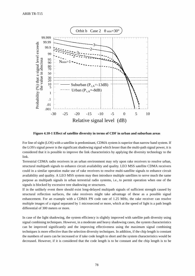
ARIB TR-T15
78
��������������������
��������������������
��������������������
��������������������
����������������������������������������
��������������������
��������������������
��������������������
�����������������������������������������������������������������������������������������������������������������������������������������������������������������������������������������������
��������������������������������������������������������������������������������������������������������������������������������������������������������������������������������������������������������������������������������������������������������������������������������������������������������������
�������������������������������������������������������������������������������������������������������������������������������������������������������
�����������������������������������������������������������������������������������������������������������������������������������������������������������������������������������������������������������������������������������������������������������������������������������������������������������������������������������������������������������������������������������������������������������������������������������������������������������������������������������������������������������������������������������������������������������������������������������������������������������������������������������������������������������������������������������������������������������������������������������������������������������������������������������������������������������������������������������������������������������������������������������������������������������������������������������������������������������������������������������������������������������������������������������������������������������������������������������������������������������������������������������������������������������������������������������������������������������������������������������������������������������������������������������������������������������������������������������������������������������������������������������������������������������������������������������������������������������������������������������������������������������������������������������������������������������������������������������������������������������������������������������������������������������������������������������������������������������������������������
��������������������������������������������������������������������������������������������������������������������������������������������������������������������������������������������������������������������������������������������������������������������������������������������������������������
�������������������������������������������������������������������������������������������������������������������������������������������������������
-30 -25 -20 -15 -10 -5 0 5 10.001
.01.1
1
51020305070809095
99
99.999.99
99.999
Relative signal level (dB)
Prob
abili
ty (%
) tha
t a si
gnal
leve
l exc
eeds
th
e va
lue
in a
bsci
ssa
Orbit b Case 2 θ min=30°
Nmin=12
31
23
Suburban (Pr,A=-13dB)Urban (Pr,A=-8dB)
Figure 4.10-1 Effect of satellite diversity in terms of CDF in urban and suburban areas For line of sight (LOS) with a satellite is predominant, CDMA system is superior than narrow band system. If the LOS's signal power is the significant shadowing signal which lesser than the multi-path signal power, it is considered that it is possible to improve the link characteristics by applying the diversity technology to the link. Terrestrial CDMA radio receivers in an urban environment may rely upon rake receivers to resolve urban, structural multipath signals to enhance circuit availability and quality. LEO MSS satellite CDMA receivers could in a similar operation make use of rake receivers to resolve multi-satellite signals to enhance circuit availability and quality. A LEO MSS system may then introduce multiple satellites to serve much the same purpose as multipath signals in urban terrestrial radio systems, i.e., to permit operation when one of the signals is blocked by excessive tree shadowing or structures. If in the unlikely event there should exist long-delayed multipath signals of sufficient strength caused by structural reflection surfaces, the rake receivers might take advantage of these as a possible signal enhancement. For an example with a CDMA PN code rate of 1.25 MHz, the rake receiver can resolve multiple images of a signal separated by 1 microsecond or more, which at the speed of light is a path length differential of 300 meters or more. In case of the light shadowing, the system efficiency is slightly improved with satellite path diversity using signal combining techniques. However, in a moderate and heavy shadowing cases, the system characteristics can be improved significantly and the improving effectiveness using the maximum signal combining techniques is more effective than the selection diversity techniques. In addition, if the chip length is constant the numbers of users can be increased or if take code length to short and the system characteristics would be decreased. However, if it is considered that the code length is to be constant and the chip length is to be
ARIB TR-T15
79
shorten, the system characteristics will be improved. Therefore, there are two approaches, which are to shorten chip length and to increase the number of diversity. The selection of the approaches should be based on the limitation of frequency bandwidth and considerations of hardware. In order to shorten the chip length it is necessary to have wider bandwidth and high speed hardware. Also, it is necessary to increase the number of hardware which must work at a same speed in order to increase the number of diversity.
In the case of CDMA , co-spreading code and use of co-frequency for communication channel are allocated, and it is transmitted at same time from LES to the multiple satellites, received at MES using RAKE receivers, the effect that it used path diversity can be gained. While the unique spreading code from MES is transmitted, the CDMA's spreading signal which receiving at same time at LES via different satellites is demodulated or after received and combined it the diversity effect can be gained by demodulating it. It is considered that the path diversity techniques are very effective to improve the system characteristics, however, it is impossible to solve the shadowing problem entirely. In addition to that, in order to realize the satellite diversity, it is necessary that there must be in the existence of satellites which have to be in Line of Sight at same time, and the communication channel have to be independently allocated at same time to the links between the satellites and the MESs. Consequently, it must be permissible that the frequency usage efficiency of the whole system is decreased. [Reference] [1] Karasawa, Y., Kimura, K. and Minamisono, K., analysis of availability improvement in LMSS by means of satellite diversity based on three-state propagation channel model,” IEEE Trans. Vehicl. Tech., vol. 46, 4, pp. 1047-1056, 1997.
ARIB TR-T15
80
4.11 Inter-Operability with Terrestrial System 4.11.1 Inter-Operability of terminals One objective of the IMT-2000 MSS vision is to extend the IMT-2000 terrestrial services universally to all areas in which users may be personally mobile. IMT-2000 MSS will largely be an extension of terrestrial wireless 3G services and capabilities, with certain modifications designed to meet the specific needs of the MSS users. It is likely that IMT-2000 services via satellite will fall into two different MES types. One will provide services limited to voice and low speed data but incorporating multi mode (satellites/terrestrials) into a handheld terminal. The other will provide IMT-2000 multimedia services to the minimum higher range data rates but with a slightly less portable terminal than a handheld. On the basis of the IMT-2000 MSS concepts above, it is required for IMT-2000 MSS to achieve the inter-operability with terrestrial networks taking into account of satellite environments. In the case of the multi mode handset, the handset will search for a terrestrial signal at first, if the signal was not found and then it will be automatically switched to search for a satellite signal. Under the circumstance where only IMT-2000 MSS network is available, it is necessary to be provided mutual inter-operability with terrestrial networks via IMT-2000 MSS networks at some level which meets user's requirements. The compatibility for user's terminal means not only co-use of same terminal but also same manner which makes user no sense of incompatibility for network selection. The compatibility requirement for channel connection protocol may be resigned because of large delay on IMT-2000 Mobile Satellite System network. 4.11.2 Inter-Operability with terrestrial network For the realization of mutual compatibility with terrestrial network via IMT-2000 MSS, the following items at least should be considered: a ) Network interface, b ) Data frame format , c ) Protocol for channel connection, d ) Co-use of User profile data, e ) Quality of service (QoS). The required level for compatibility achievement is slightly different for each of them. The compatibility of functions for each network such as item a) and c) should be mandatory. Most available compatibility such as item b) and d), is required for the reduction of data conversion process at MES or LES. In order to realize the transparency for QoS on a channel with terrestrial network, negotiation function which determines the QoS is required to be activated during the channel is being connected. For the assumption of this negotiation function, each network should have a same level of QoS within the limitation of necessary quality and channel capability. Definition of QoS on IMT-2000 terrestrial systems as described below; The IMT-2000 terrestrial systems shall support the set-up, re-negotiation and clearing of connections with a range of traffic and performance characteristics. The re-negotiation of QoS attributes / bearer attributes may result from an upper layer request or a change in the radio conditions (handover, cell load modification,...) and may be mobile station (e.g. by an application or the user via an application) or network initiated. It shall be possible for the UTRAN to apply the
ARIB TR-T15
81
following traffic policing mechanisms such as : . connection admission control (CAC) during connection set-up and re-negotiation, . flow control (FC) on a connection during its lifetime, . usage parameter control (UPC) on a connection during its lifetime..
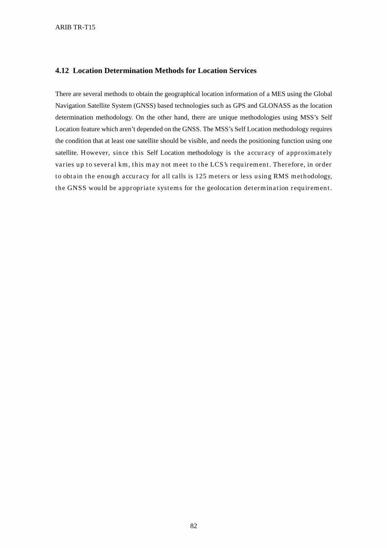
ARIB TR-T15
82
4.12 Location Determination Methods for Location Services
There are several methods to obtain the geographical location information of a MES using the Global
Navigation Satellite System (GNSS) based technologies such as GPS and GLONASS as the location
determination methodology. On the other hand, there are unique methodologies using MSS’s Self
Location feature which aren’t depended on the GNSS. The MSS’s Self Location methodology requires
the condition that at least one satellite should be visible, and needs the positioning function using one
satellite. However, since this Self Location methodology is the accuracy of approximately varies up to several km, this may not meet to the LCS’s requirement. Therefore, in order to obtain the enough accuracy for all calls is 125 meters or less using RMS methodology, the GNSS would be appropriate systems for the geolocation determination requirement.
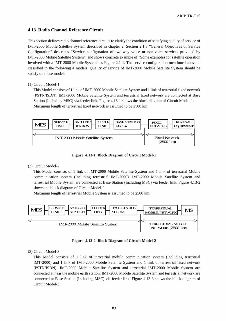
ARIB TR-T15
83
4.13 Radio Channel Reference Circuit This section defines radio channel reference circuits to clarify the condition of satisfying quality of service of IMT-2000 Mobile Satellite System described in chapter 2. Section 2.1.3 ”General Objectives of Service Configuration” describes “Service configuration of two-way voice or non-voice services provided by IMT-2000 Mobile Satellite System”, and shows concrete example of ”Some examples for satellite operation involved with a IMT-2000 Mobile System” as Figure 2.1-1. The service configuration mentioned above is classified to the following 4 models. Quality of service of IMT-2000 Mobile Satellite System should be satisfy on those models (1) Circuit Model-1
This Model consists of 1 link of IMT-2000 Mobile Satellite System and 1 link of terrestrial fixed network (PSTN/ISDN). IMT-2000 Mobile Satellite System and terrestrial fixed network are connected at Base Station (Including MSC) via feeder link. Figure 4.13-1 shows the block diagram of Circuit Model-1. Maximum length of terrestrial fixed network is assumed to be 2500 km.
Figure 4.13-1 Block Diagram of Circuit Model-1
(2) Circuit Model-2
This Model consists of 1 link of IMT-2000 Mobile Satellite System and 1 link of terrestrial Mobile communication system (Including terrestrial IMT-2000). IMT-2000 Mobile Satellite System and terrestrial Mobile System are connected at Base Station (Including MSC) via feeder link. Figure 4.13-2 shows the block diagram of Circuit Model-2. Maximum length of terrestrial Mobile System is assumed to be 2500 km.
Figure 4.13-2 Block Diagram of Circuit Model-2
(3) Circuit Model-3
This Model consists of 1 link of terrestrial mobile communication system (Including terrestrial IMT-2000) and 1 link of IMT-2000 Mobile Satellite System and 1 link of terrestrial fixed network (PSTN/ISDN). IMT-2000 Mobile Satellite System and terrestrial IMT-2000 Mobile System are connected at near the mobile earth station. IMT-2000 Mobile Satellite System and terrestrial network are connected at Base Station (Including MSC) via feeder link. Figure 4.13-3 shows the block diagram of Circuit Model-3.
Fixed Network(2500 km)
SERVICELINK
SATLLITESTATION
BASE STATIONMSC etc.
FEEDERLINKMES FIXED
NETWORKTREMINALEQUIPMENT
IMT-2000 Mobile Satellite System
TERRESTRIAL MOBILENETWORK (2500 km)
IMT-2000 Mobile Satellite System
SERVICELINK
SATLLITESTATION
BASE STATIONMSC etc.
FEEDERLINKMES TERRESTRIAL
MOBILE NETWORK MS
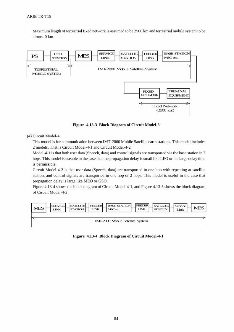
ARIB TR-T15
84
Maximum length of terrestrial fixed network is assumed to be 2500 km and terrestrial mobile system to be almost 0 km.
Figure 4.13-3 Block Diagram of Circuit Model-3
(4) Circuit Model-4
This model is for communication between IMT-2000 Mobile Satellite earth stations. This model includes 2 models. That is Circuit Model-4-1 and Circuit Model-4-2 Model-4-1 is that both user data (Speech, data) and control signals are transported via the base station in 2 hops. This model is useable in the case that the propagation delay is small like LEO or the large delay time is permissible. Circuit Model-4-2 is that user data (Speech, data) are transported in one hop with repeating at satellite station, and control signals are transported in one hop or 2 hops. This model is useful in the case that propagation delay is large like MEO or GSO. Figure 4.13-4 shows the block diagram of Circuit Model-4-1, and Figure 4.13-5 shows the block diagram of Circuit Model-4-2
Figure 4.13-4 Block Diagram of Circuit Model-4-1
CELLSTATION
TERRESTRIALMOBILE SYSTEM
IMT-2000 Mobile Satellite System
Fixed Network(2500 km)
SERVICELINK
SATLLITESTATION
BASE STATIONMSC etc.
FEEDERLINKMESPS
FIXEDNETWORK
TREMINALEQUIPMENT
SERVICELINK
SATLLITESTATION
BASE STATIONMSC etc.
FEEDERLINK
IMT-2000 Mobile Satellite System
MESFEEDERLINK
ServiceLink
SATLLITESTATION MES
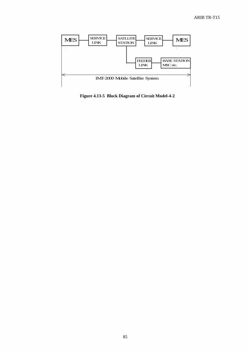
ARIB TR-T15
85
Figure 4.13-5 Block Diagram of Circuit Model-4-2
SERVICELINK
SATLLITESTATION
BASE STATIONMSC etc.
FEEDERLINK
MES SERVICELINK
MES
IMT-2000 Mobile Satellite System
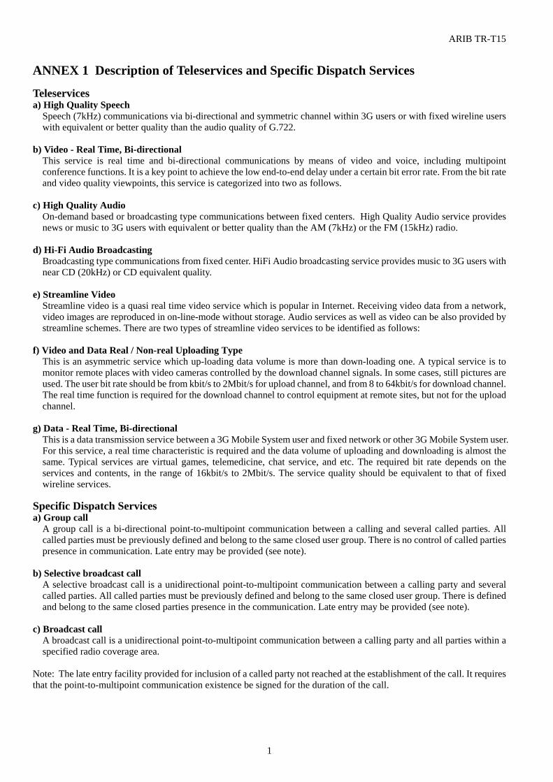
ARIB TR-T15
1
ANNEX 1 Description of Teleservices and Specific Dispatch Services Teleservices a) High Quality Speech
Speech (7kHz) communications via bi-directional and symmetric channel within 3G users or with fixed wireline users with equivalent or better quality than the audio quality of G.722.
b) Video - Real Time, Bi-directional
This service is real time and bi-directional communications by means of video and voice, including multipoint conference functions. It is a key point to achieve the low end-to-end delay under a certain bit error rate. From the bit rate and video quality viewpoints, this service is categorized into two as follows.
c) High Quality Audio
On-demand based or broadcasting type communications between fixed centers. High Quality Audio service provides news or music to 3G users with equivalent or better quality than the AM (7kHz) or the FM (15kHz) radio.
d) Hi-Fi Audio Broadcasting
Broadcasting type communications from fixed center. HiFi Audio broadcasting service provides music to 3G users with near CD (20kHz) or CD equivalent quality.
e) Streamline Video
Streamline video is a quasi real time video service which is popular in Internet. Receiving video data from a network, video images are reproduced in on-line-mode without storage. Audio services as well as video can be also provided by streamline schemes. There are two types of streamline video services to be identified as follows:
f) Video and Data Real / Non-real Uploading Type
This is an asymmetric service which up-loading data volume is more than down-loading one. A typical service is to monitor remote places with video cameras controlled by the download channel signals. In some cases, still pictures are used. The user bit rate should be from kbit/s to 2Mbit/s for upload channel, and from 8 to 64kbit/s for download channel. The real time function is required for the download channel to control equipment at remote sites, but not for the upload channel.
g) Data - Real Time, Bi-directional
This is a data transmission service between a 3G Mobile System user and fixed network or other 3G Mobile System user. For this service, a real time characteristic is required and the data volume of uploading and downloading is almost the same. Typical services are virtual games, telemedicine, chat service, and etc. The required bit rate depends on the services and contents, in the range of 16kbit/s to 2Mbit/s. The service quality should be equivalent to that of fixed wireline services.
Specific Dispatch Services a) Group call
A group call is a bi-directional point-to-multipoint communication between a calling and several called parties. All called parties must be previously defined and belong to the same closed user group. There is no control of called parties presence in communication. Late entry may be provided (see note).
b) Selective broadcast call
A selective broadcast call is a unidirectional point-to-multipoint communication between a calling party and several called parties. All called parties must be previously defined and belong to the same closed user group. There is defined and belong to the same closed parties presence in the communication. Late entry may be provided (see note).
c) Broadcast call
A broadcast call is a unidirectional point-to-multipoint communication between a calling party and all parties within a specified radio coverage area.
Note: The late entry facility provided for inclusion of a called party not reached at the establishment of the call. It requires that the point-to-multipoint communication existence be signed for the duration of the call.
ARIB TR-T15
2
ANNEX 2 Consideration of Voice CODEC
The selected Mandatory Voice Coding schemes for IMT2000 DS-CDMA are AMR Speech Codec. AMR
is an abbreviation of Adaptive Multi-Rate. The Multi-Rate Speech Coder is a single integrated speech Codec with
eight source rates from 4.7k bit/s to 12.2 kbit/s and a low rate background noise encoding mode. The speech coder
is capable of switching its bit-rate every 20 ms speech frame upon command. It contain the three enhanced currently
used Codec, One is AMR_12.2(12.2 kbit/s : GSM FER), second is AMR_7.4 (7.4 kbit/s : IS-641), and third is
AMR_6.70(6.70 kbit/s : PDC-EFR ).
The selected Voice Coding schemes for IMT2000 MC-CDMA are QCELP and there are three Options.
One is 14.4 kbit/s QCELP, and second is 9.6 kbit/s QCELP, third is EVRC(Enhanced Variable Rate Coder) . EVRC
is used to digitally encode the speech signal for transmission at a variable data rate of 8550, 4000, 2000, or 800 bit/s.
To ensure the Commonality and/or Compatibility between 3G MSS and IMT2000 Terrestrial system(s), It
is desirable that same type of Coding schemes should be selected for 3G MSS. Considering the limitation of
Transmission Capacity of 3G MSS, lower data rate codec such as 2 kbit/s data rate should be added for 3G MSS.
The adoption of lower data rate codec should be depends on the operator’s choice.
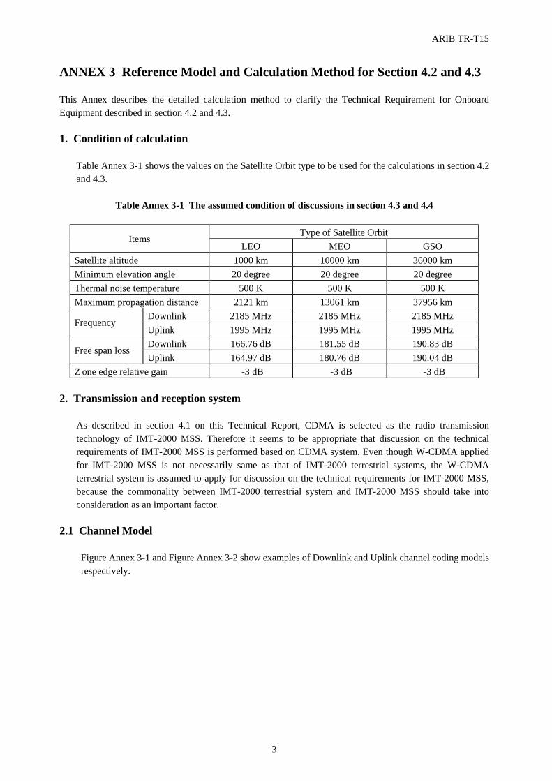
ARIB TR-T15
3
ANNEX 3 Reference Model and Calculation Method for Section 4.2 and 4.3 This Annex describes the detailed calculation method to clarify the Technical Requirement for Onboard Equipment described in section 4.2 and 4.3. 1. Condition of calculation
Table Annex 3-1 shows the values on the Satellite Orbit type to be used for the calculations in section 4.2 and 4.3.
Table Annex 3-1 The assumed condition of discussions in section 4.3 and 4.4
Type of Satellite Orbit
Items LEO MEO GSO
Satellite altitude 1000 km 10000 km 36000 km Minimum elevation angle 20 degree 20 degree 20 degree Thermal noise temperature 500 K 500 K 500 K Maximum propagation distance 2121 km 13061 km 37956 km
Downlink 2185 MHz 2185 MHz 2185 MHz Frequency
Uplink 1995 MHz 1995 MHz 1995 MHz Downlink 166.76 dB 181.55 dB 190.83 dB
Free span loss Uplink 164.97 dB 180.76 dB 190.04 dB
Zone edge relative gain -3 dB -3 dB -3 dB 2. Transmission and reception system
As described in section 4.1 on this Technical Report, CDMA is selected as the radio transmission technology of IMT-2000 MSS. Therefore it seems to be appropriate that discussion on the technical requirements of IMT-2000 MSS is performed based on CDMA system. Even though W-CDMA applied for IMT-2000 MSS is not necessarily same as that of IMT-2000 terrestrial systems, the W-CDMA terrestrial system is assumed to apply for discussion on the technical requirements for IMT-2000 MSS, because the commonality between IMT-2000 terrestrial system and IMT-2000 MSS should take into consideration as an important factor.
2.1 Channel Model
Figure Annex 3-1 and Figure Annex 3-2 show examples of Downlink and Uplink channel coding models respectively.
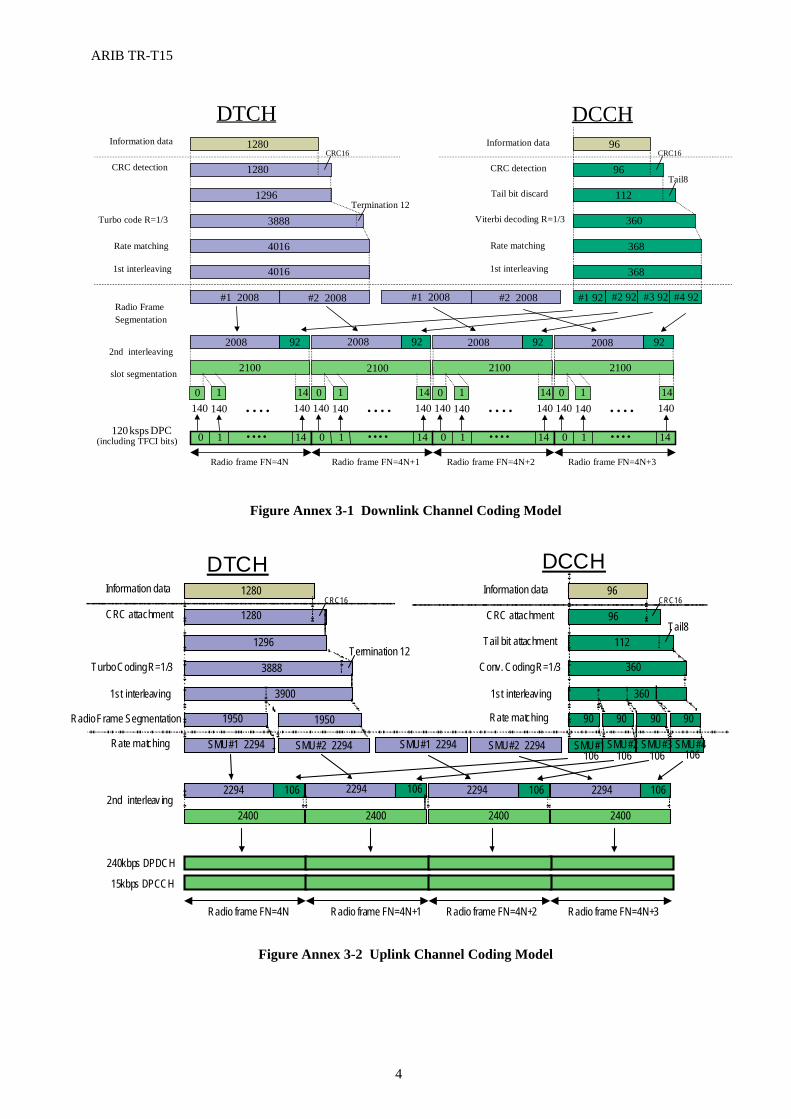
ARIB TR-T15
4
Figure Annex 3-1 Downlink Channel Coding Model
Figure Annex 3-2 Uplink Channel Coding Model
Turbo code R=1/3
Radio frame FN=4N+1 Radio frame FN=4N+2 Radio frame FN=4N+3Radio frame FN=4N
Information data
CRC detection
2nd interleaving
2100
2008 92 2008 92 2008 92 2008
#1 2008 #2 2008 #1 92 #2 92 #3 92 #4 92
2100 2100 2100
4016
3888
1296
CRC16
1280
1280
92
368
360
96CRC16
Rate matching
1st interleaving
CRC detection
Information data
DTCH DCCH
4016
#1 2008 #2 2008
368
96
Radio FrameSegmentation
slot segmentation
120ksps DPCH (including TFCI bits)
Rate matching
1st interleaving
0 1 14• • • •
140 1400 1
140• • • •
14
0 1 14• • • •
140 1400 1
140• • • •
14
0 1 14• • • •
140 1400 1
140• • • •
14
0 1 14• • • •
140 1400 1
140• • • •
14
Termination 12112
Tail8Tail bit discard
Viterbi decoding R=1/3
240 kbps DPDCH
Turbo Coding R=1/3
Radio frame FN=4N+1 Radio frame FN=4N+2 Radio frame FN=4N+3 Radio frame FN=4N
Information data
CRC attachment
2nd interleav ing 2400
2294 106 2294 106 2294 106 2294
SMU#1 2294 SMU#2 2294 SMU#1 106
SMU#2 106
SMU#3 106
SMU#4 106
2400 2400 2400
1950
3888
1296 Termination 12
CRC16 1280
1280
106
360
360
112 Tail8
96
1st interleaving
CRC attachment
Information data
Tail bit attachment
Conv. Coding R=1/3
Rate matching
1st interleaving
DTCH DCCH
3900
1950
SMU#1 2294 SMU#2 2294
90 90 90 90
15 kbps DPCCH
Rate matching
Radio Frame Segmentation
96 CRC16
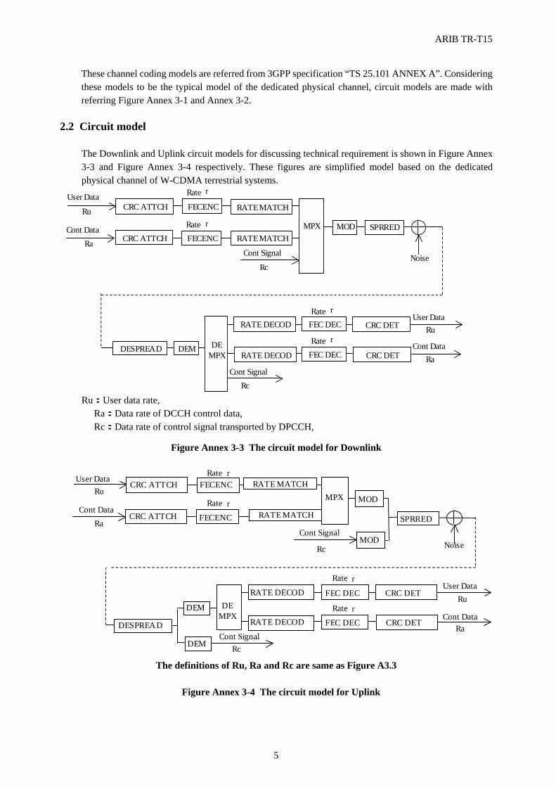
ARIB TR-T15
5
These channel coding models are referred from 3GPP specification “TS 25.101 ANNEX A”. Considering these models to be the typical model of the dedicated physical channel, circuit models are made with referring Figure Annex 3-1 and Annex 3-2.
2.2 Circuit model
The Downlink and Uplink circuit models for discussing technical requirement is shown in Figure Annex 3-3 and Figure Annex 3-4 respectively. These figures are simplified model based on the dedicated physical channel of W-CDMA terrestrial systems.
Ru:User data rate, Ra:Data rate of DCCH control data, Rc:Data rate of control signal transported by DPCCH,
Figure Annex 3-3 The circuit model for Downlink
The definitions of Ru, Ra and Rc are same as Figure A3.3
Figure Annex 3-4 The circuit model for Uplink
FECENC
DESPREAD DEM
FEC DEC
User Data
Cont Data
Cont Signal
DE
MPX
User Data
Cont Data
Cont Signal
Noise
Rate:r
Rate:r
Ru
Ra
Rc
Rc
Ru
Ra
CRC ATTCH
FECENC CRC ATTCH SPRRED
RATE MATCH
RATE MATCH MOD
MPX
RATE DECOD
RATE DECOD
CRC DET
FEC DEC CRC DET
Rate:r
Rate:r
r
r
r
r
FECENC
DESPREAD
DEM
FEC DEC
User Data
Cont Data
Cont Signal
DE MPX
User Data
Cont Data
Cont Signal
Noise
Rate:r
Rate:r
Ru
Ra
Rc
Rc
Ru
Ra
CRC ATTCH
FECENC CRC ATTCH SPRRED
RATE MATCH
RATE MATCH
MOD
MPX
RATE DECOD
RATE DECOD
CRC DET
FEC DEC CRC DET
Rate:r
Rate:r
MOD
DEM
r
r
r
r
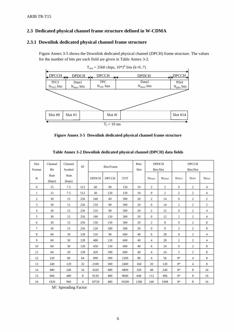
ARIB TR-T15
6
2.3 Dedicated physical channel frame structure defined in W-CDMA 2.3.1 Downlink dedicated physical channel frame structure
Figure Annex 3-5 shows the Downlink dedicated physical channel (DPCH) frame structure. The values for the number of bits per each field are given in Table Annex 3-2.
Figure Annex 3-5 Downlink dedicated physical channel frame structure
Table Annex 3-2 Downlink dedicated physical channel (DPCH) data fields
Slot
Format
Channel
Bit
Channel
Symbol SF Bits/Frame
Bits/
Slot
DPDCH
Bits/Slot
DPCCH
Bits/Slot
#i Rate
(kbps)
Rate
(ksps) DPDCH DPCCH TOT NData1 NData2 NTFCI NTPC NPilot
0 15 7.5 512 60 90 150 10 2 2 0 2 4
1 15 7.5 512 30 120 150 10 0 2 2 2 4
2 30 15 256 240 60 300 20 2 14 0 2 2
3 30 15 256 210 90 300 20 0 14 2 2 2
4 30 15 256 210 90 300 20 2 12 0 2 4
5 30 15 256 180 120 300 20 0 12 2 2 4
6 30 15 256 150 150 300 20 2 8 0 2 8
7 30 15 256 120 180 300 20 0 8 2 2 8
8 60 30 128 510 90 600 40 6 28 0 2 4
9 60 30 128 480 120 600 40 4 28 2 2 4
10 60 30 128 450 150 600 40 6 24 0 2 8
11 60 30 128 420 180 600 40 4 24 2 2 8
12 120 60 64 900 300 1200 80 4 56 8* 4 8
13 240 120 32 2100 300 2400 160 20 120 8* 4 8
14 480 240 16 4320 480 4800 320 48 240 8* 8 16
15 960 480 8 9120 480 9600 640 112 496 8* 8 16
16 1920 960 4 18720 480 19200 1280 240 1008 8* 8 16
SF: Spreading Factor
TPC NTPC bits
Slot #0 Slot #1 Slot #i Slot #14
Tslot = 2560 chips, 10*2k bits (k=0..7)
Data2Ndata2 bits
DPDCH
Tf = 10 ms
TFCI NTFCI bits
Pilot Npilot bits
Data1Ndata1 bits
DPCCH DPDCH DPCCH DPCCH
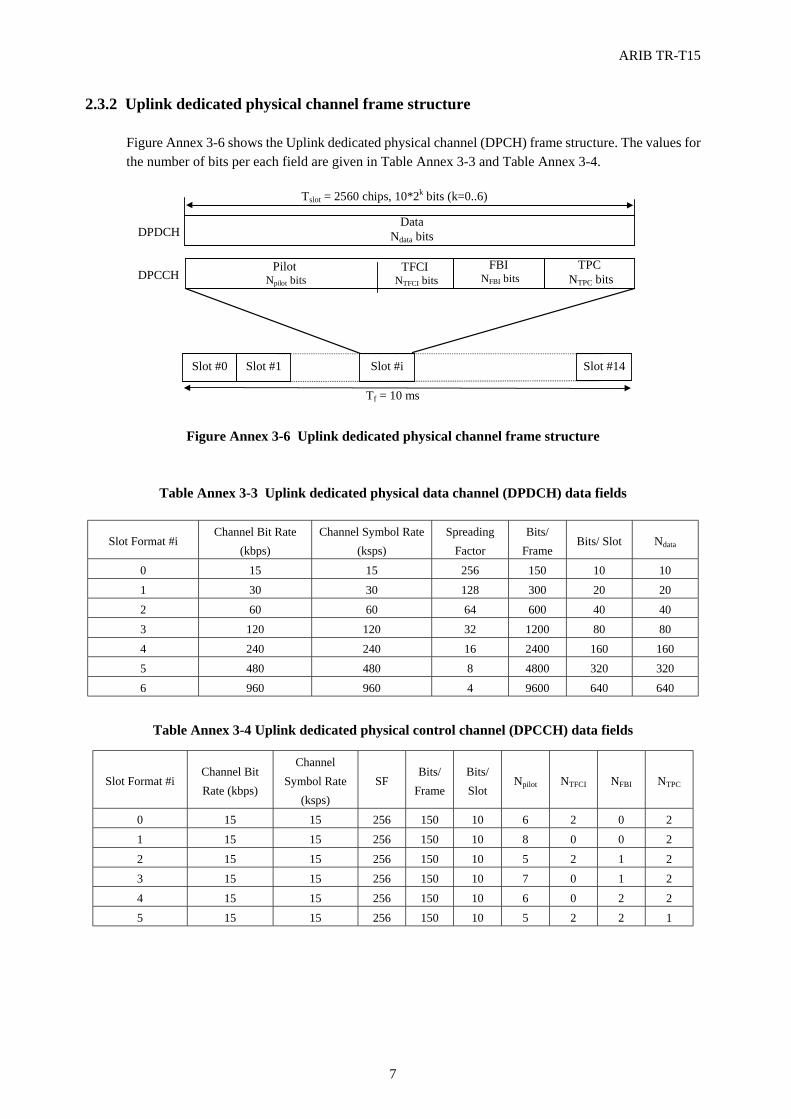
ARIB TR-T15
7
2.3.2 Uplink dedicated physical channel frame structure Figure Annex 3-6 shows the Uplink dedicated physical channel (DPCH) frame structure. The values for the number of bits per each field are given in Table Annex 3-3 and Table Annex 3-4.
Figure Annex 3-6 Uplink dedicated physical channel frame structure
Table Annex 3-3 Uplink dedicated physical data channel (DPDCH) data fields
Slot Format #i Channel Bit Rate
(kbps) Channel Symbol Rate
(ksps) Spreading
Factor Bits/
Frame Bits/ Slot Ndata
0 15 15 256 150 10 10 1 30 30 128 300 20 20
2 60 60 64 600 40 40
3 120 120 32 1200 80 80 4 240 240 16 2400 160 160 5 480 480 8 4800 320 320 6 960 960 4 9600 640 640
Table Annex 3-4 Uplink dedicated physical control channel (DPCCH) data fields
Slot Format #i Channel Bit Rate (kbps)
Channel Symbol Rate
(ksps) SF
Bits/ Frame
Bits/ Slot
Npilot NTFCI NFBI NTPC
0 15 15 256 150 10 6 2 0 2
1 15 15 256 150 10 8 0 0 2
2 15 15 256 150 10 5 2 1 2
3 15 15 256 150 10 7 0 1 2
4 15 15 256 150 10 6 0 2 2 5 15 15 256 150 10 5 2 2 1
Pilot Npilot bits
TPC NTPC bits
DataNdata bits
Slot #0 Slot #1 Slot #i Slot #14
Tslot = 2560 chips, 10*2k bits (k=0..6)
Tf = 10 ms
DPDCH
DPCCHFBI
NFBI bitsTFCI
NTFCI bits
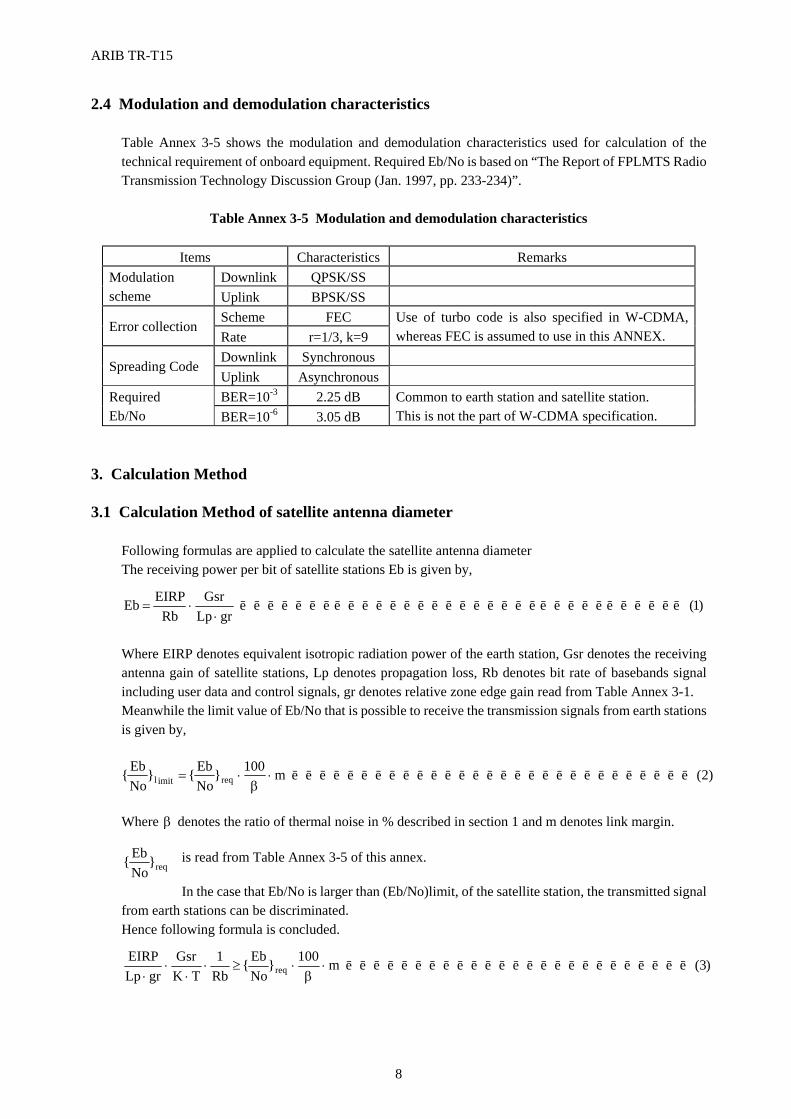
ARIB TR-T15
8
2.4 Modulation and demodulation characteristics Table Annex 3-5 shows the modulation and demodulation characteristics used for calculation of the technical requirement of onboard equipment. Required Eb/No is based on “The Report of FPLMTS Radio Transmission Technology Discussion Group (Jan. 1997, pp. 233-234)”.
Table Annex 3-5 Modulation and demodulation characteristics
Items Characteristics Remarks
Downlink QPSK/SS Modulation scheme Uplink BPSK/SS
Scheme FEC Error collection
Rate r=1/3, k=9 Use of turbo code is also specified in W-CDMA, whereas FEC is assumed to use in this ANNEX.
Downlink Synchronous Spreading Code
Uplink Asynchronous BER=10-3 2.25 dB Required
Eb/No BER=10-6 3.05 dB Common to earth station and satellite station. This is not the part of W-CDMA specification.
3. Calculation Method 3.1 Calculation Method of satellite antenna diameter
Following formulas are applied to calculate the satellite antenna diameter The receiving power per bit of satellite stations Eb is given by,
)1(grLp
GsrRb
EIRPEb LLLLLLLLLLLLLLLLLLLLLLLLLLLLLLLLL⋅
⋅=
Where EIRP denotes equivalent isotropic radiation power of the earth station, Gsr denotes the receiving antenna gain of satellite stations, Lp denotes propagation loss, Rb denotes bit rate of basebands signal including user data and control signals, gr denotes relative zone edge gain read from Table Annex 3-1. Meanwhile the limit value of Eb/No that is possible to receive the transmission signals from earth stations is given by,
)2(m100}NoEb{}
NoEb{ reqimitl LLLLLLLLLLLLLLLLLLLLLLLLLLLLL⋅
β⋅=
Where β denotes the ratio of thermal noise in % described in section 1 and m denotes link margin.
is read from Table Annex 3-5 of this annex. In the case that Eb/No is larger than (Eb/No)limit, of the satellite station, the transmitted signal
from earth stations can be discriminated. Hence following formula is concluded.
)3(m100}NoEb{
Rb1
TKGsr
grLpEIRP
req LLLLLLLLLLLLLLLLLLLLLLLLL⋅β
⋅≥⋅⋅
⋅⋅
req}NoEb{
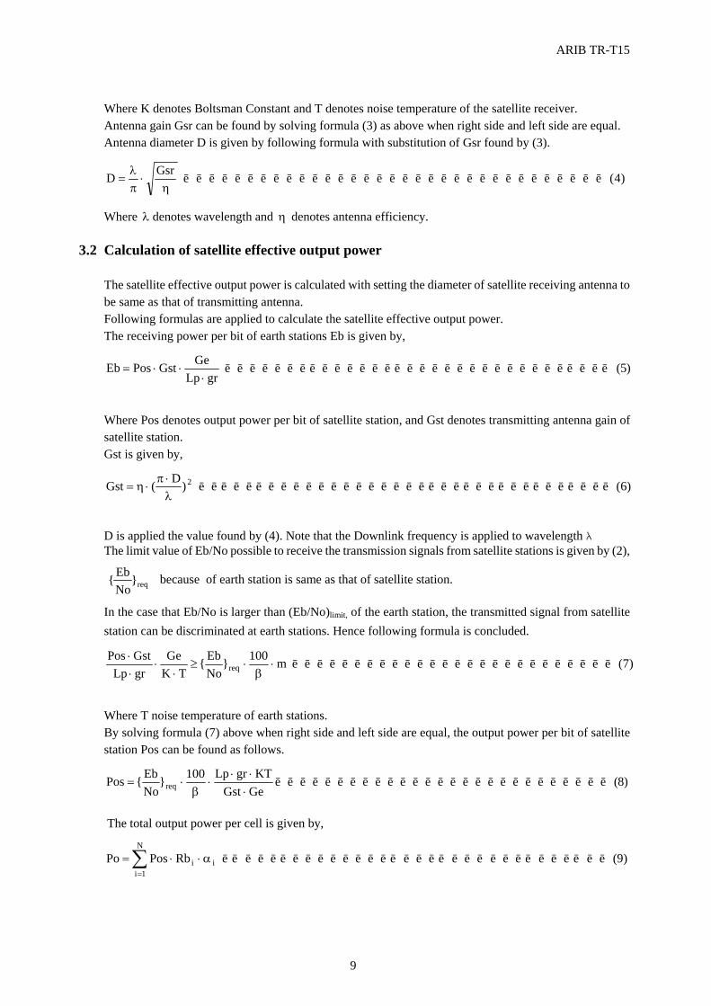
ARIB TR-T15
9
req}NoEb{
Where K denotes Boltsman Constant and T denotes noise temperature of the satellite receiver. Antenna gain Gsr can be found by solving formula (3) as above when right side and left side are equal. Antenna diameter D is given by following formula with substitution of Gsr found by (3).
)4(GsrD LLLLLLLLLLLLLLLLLLLLLLLLLLLLLLLLLη
⋅πλ
=
Where λ denotes wavelength and η denotes antenna efficiency.
3.2 Calculation of satellite effective output power The satellite effective output power is calculated with setting the diameter of satellite receiving antenna to be same as that of transmitting antenna. Following formulas are applied to calculate the satellite effective output power. The receiving power per bit of earth stations Eb is given by,
)5(grLp
GeGstPosEb LLLLLLLLLLLLLLLLLLLLLLLLLLLLLLLL⋅
⋅⋅=
Where Pos denotes output power per bit of satellite station, and Gst denotes transmitting antenna gain of satellite station. Gst is given by,
)6()D(Gst 2 LLLLLLLLLLLLLLLLLLLLLLLLLLLLLLLLLLLλ⋅π
⋅η=
D is applied the value found by (4). Note that the Downlink frequency is applied to wavelength λ The limit value of Eb/No possible to receive the transmission signals from satellite stations is given by (2), because of earth station is same as that of satellite station. In the case that Eb/No is larger than (Eb/No)limit, of the earth station, the transmitted signal from satellite station can be discriminated at earth stations. Hence following formula is concluded.
)7(m100}NoEb{
TKGe
grLpGstPos
req LLLLLLLLLLLLLLLLLLLLLLLLLL⋅β
⋅≥⋅
⋅⋅⋅
Where T noise temperature of earth stations. By solving formula (7) above when right side and left side are equal, the output power per bit of satellite station Pos can be found as follows.
)8(GeGstKTgrLp100}
NoEb{Pos req LLLLLLLLLLLLLLLLLLLLLLLLLLL
⋅⋅⋅
⋅β
⋅=
The total output power per cell is given by,
)9(RbPosPo i
N
1ii LLLLLLLLLLLLLLLLLLLLLLLLLLLLLLLLα⋅⋅= ∑
=
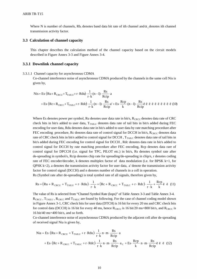
ARIB TR-T15
10
Where N is number of channels, Rbi denotes band data bit rate of ith channel and iα denotes ith channel transmission activity factor.
3.3 Calculation of channel capacity
This chapter describes the calculation method of the channel capacity based on the circuit models described in Figure Annex 3-3 and Figure Annex 3-4.
3.3.1 Downlink channel capacity 3.3.1.1 Channel capacity for asynchronous CDMA
Co-channel interference noise of asynchronous CDMA produced by the channels in the same cell Nis is given by,
( )
( ) )10(RcipRs)1n(
kRcpEs'a
RcipRs)1n(
kr1RdcrTRRcEs
aRcipRs)1n(
kr1RdurTRRuEsNis
TAILCCRCC
TAILUCRCU
LLLLLLLLLL⋅−⋅⋅+⋅−⋅
⋅⋅+++⋅+
⋅⋅−⋅
⋅⋅+++⋅=
Where Es denotes power per symbol, Ru denotes user data rate in bit/s, RCRCU denotes data rate of CRC check bits in bit/s added to user data, TTAILU denotes data rate of tail bits in bit/s added during FEC encoding for user data, Rdu denotes data rate in bit/s added to user data by rate matching procedure after FEC encoding procedure, Rc denotes data rate of control signal for DCCH in bit/s, RCRCC denotes data rate of CRC check bits in bit/s added to control signal for DCCH , TTAILC denotes data rate of tail bits in bit/s added during FEC encoding for control signal for DCCH , Rdc denotes data rate in bit/s added to control signal for DCCH by rate matching procedure after FEC encoding, Rcp denotes data rare of control signal for DPCCH (i.e. signal for TPC, PILOT etc.) in bit/s, Rs denotes symbol rate after de-spreading in symbol/s, Rcip denotes chip rate for spreading/de-spreading in chip/s, r denotes coding rate of FEC encoder/decoder, k denotes multiplex factor of data modulation (i.e. for BPSK k=1, for QPSK k=2), a denotes the transmission activity factor for user data, 'a denote the transmission activity factor for control signal (DCCH) and n denotes number of channels in a cell in operation. Rs (Symbol rate after de-spreading) is total symbol rate of all signals, therefore given by,
( ) ( ) )11(k
Rcpkr
1RdcrTRRckr
1RdurTRRuRs TAILCCRCCTAILUCRCU LL+⋅
⋅⋅++++⋅
⋅⋅+++=
The value of Rs is selected from “Channel Symbol Rate (ksps)” of Table Annex 3-3 and Table Annex 3-4. RCRCU , TTAILU , RCRCC and TTAILC are found by following. For the case of channel coding model shown in Figure Annex 3-1, CRC check bits for user data (DTCH) is 16 bit for every 20 ms and CRC check bits for control data (DCCH) is 16 bit for every 40 ms, hence RCRCU is 16 bit/20 ms=800 bit/s, and RCRCC is 16 bit/40 ms=400 bit/s, and so forth. Co-channel interference noise of asynchronous CDMA produced by the adjacent cell after de-spreading of received signal Nia is given by,
( )
( ) )12(RcipRsmn
kRcpEsa
RcipRsmn
kr1RdcrTRRcEs
aRcipRsmn
kr1RdurTRRuEsNia
CTAILCCRCC
TAILUCRCU
LLL⋅⋅⋅⋅+⋅⋅⋅⋅
⋅⋅+++⋅+
⋅⋅⋅⋅
⋅⋅+++⋅=
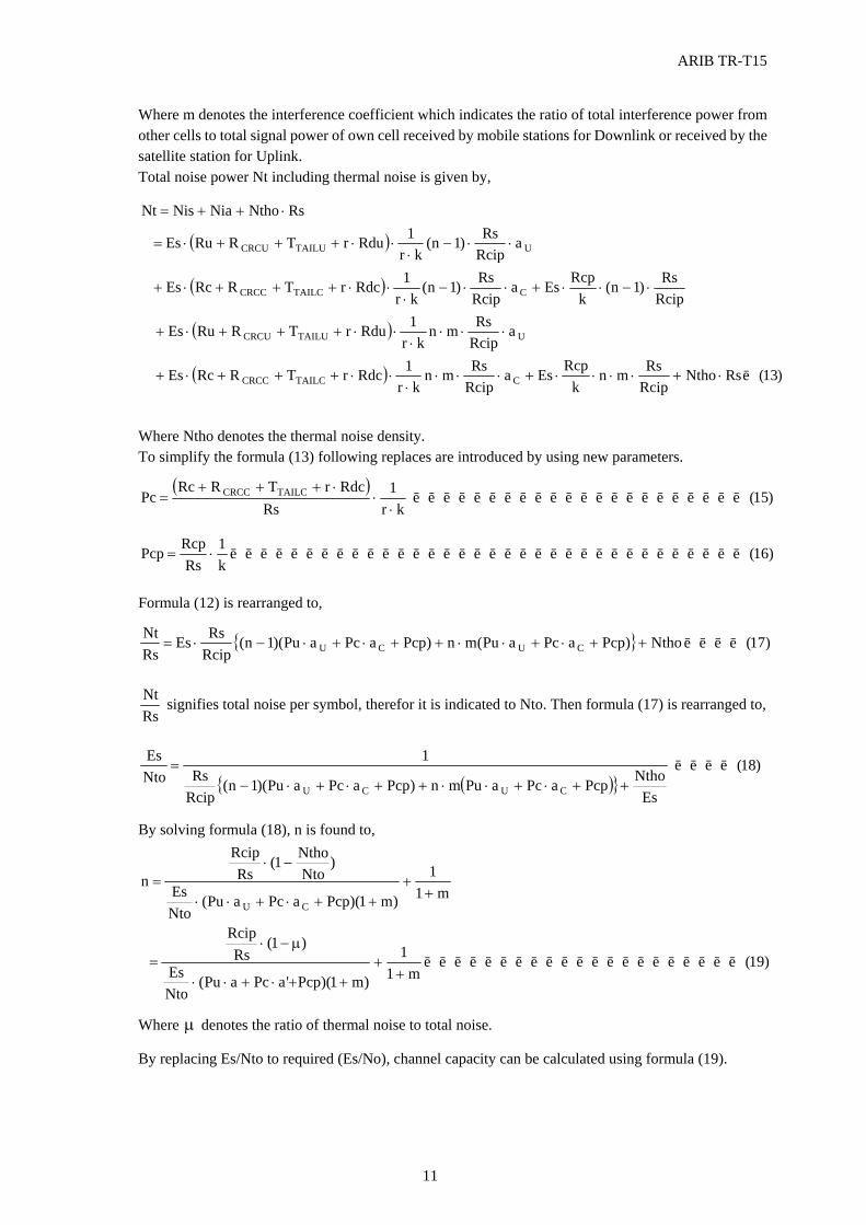
ARIB TR-T15
11
Where m denotes the interference coefficient which indicates the ratio of total interference power from other cells to total signal power of own cell received by mobile stations for Downlink or received by the satellite station for Uplink. Total noise power Nt including thermal noise is given by,
( )
( )
( )
( ) )13(RsNthoRcipRsmn
kRcpEsa
RcipRsmn
kr1RdcrTRRcEs
aRcipRsmn
kr1RdurTRRuEs
RcipRs)1n(
kRcpEsa
RcipRs)1n(
kr1RdcrTRRcEs
aRcipRs)1n(
kr1RdurTRRuEs
RsNthoNiaNisNt
CTAILCCRCC
UTAILUCRCU
CTAILCCRCC
UTAILUCRCU
L⋅+⋅⋅⋅⋅+⋅⋅⋅⋅
⋅⋅+++⋅+
⋅⋅⋅⋅
⋅⋅+++⋅+
⋅−⋅⋅+⋅⋅−⋅
⋅⋅+++⋅+
⋅⋅−⋅
⋅⋅+++⋅=
⋅++=
Where Ntho denotes the thermal noise density. To simplify the formula (13) following replaces are introduced by using new parameters.
( ))15(
kr1
RsRdcrTRRc
Pc TAILCCRCC LLLLLLLLLLLLLLLLLLLLLL⋅
⋅⋅+++
=
)16(k1
RsRcpPcp LLLLLLLLLLLLLLLLLLLLLLLLLLLLLLLLLL⋅=
Formula (12) is rearranged to,
{ } )17(Ntho)PcpaPcaPu(mn)PcpaPcaPu)(1n(RcipRsEs
RsNt
CUCU LLLL++⋅+⋅⋅++⋅+⋅−⋅=
RsNt signifies total noise per symbol, therefor it is indicated to Nto. Then formula (17) is rearranged to,
( ){ })18(
EsNthoPcpaPcaPumn)PcpaPcaPu)(1n(
RcipRs
1NtoEs
CUCU
LLLL++⋅+⋅⋅++⋅+⋅−
=
By solving formula (18), n is found to,
)19(m1
1
)m1)(Pcp'aPcaPu(NtoEs
)1(Rs
Rcip
m11
)m1)(PcpaPcaPu(NtoEs
)Nto
Ntho1(Rs
Rcip
nCU
LLLLLLLLLLLLLLLLLLLLL+
+++⋅+⋅⋅
µ−⋅=
++
++⋅+⋅⋅
−⋅=
Where µ denotes the ratio of thermal noise to total noise.
By replacing Es/Nto to required (Es/No), channel capacity can be calculated using formula (19).
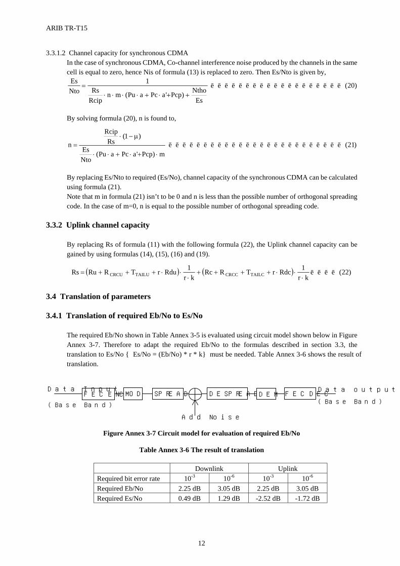
ARIB TR-T15
12
3.3.1.2 Channel capacity for synchronous CDMA In the case of synchronous CDMA, Co-channel interference noise produced by the channels in the same cell is equal to zero, hence Nis of formula (13) is replaced to zero. Then Es/Nto is given by,
)20(
EsNtho)Pcp'aPcaPu(mn
RcipRs
1NtoEs
LLLLLLLLLLLLLLLLLLL++⋅+⋅⋅⋅⋅
=
By solving formula (20), n is found to,
)21(m)Pcp'aPcaPu(
NtoEs
)1(Rs
Rcip
n LLLLLLLLLLLLLLLLLLLLLLLLL⋅+⋅+⋅⋅
µ−⋅=
By replacing Es/Nto to required (Es/No), channel capacity of the synchronous CDMA can be calculated using formula (21). Note that m in formula (21) isn’t to be 0 and n is less than the possible number of orthogonal spreading code. In the case of m=0, n is equal to the possible number of orthogonal spreading code.
3.3.2 Uplink channel capacity
By replacing Rs of formula (11) with the following formula (22), the Uplink channel capacity can be gained by using formulas (14), (15), (16) and (19).
( ) ( ) )22(kr
1RdcrTRRckr
1RdurTRRuRs TAILCCRCCTAILUCRCU LLLL⋅
⋅⋅++++⋅
⋅⋅+++=
3.4 Translation of parameters 3.4.1 Translation of required Eb/No to Es/No
The required Eb/No shown in Table Annex 3-5 is evaluated using circuit model shown below in Figure Annex 3-7. Therefore to adapt the required Eb/No to the formulas described in section 3.3, the translation to Es/No { Es/No = (Eb/No) * r * k} must be needed. Table Annex 3-6 shows the result of translation.
Figure Annex 3-7 Circuit model for evaluation of required Eb/No
Table Annex 3-6 The result of translation
Downlink Uplink Required bit error rate 10-3 10-6 10-3 10-6 Required Eb/No 2.25 dB 3.05 dB 2.25 dB 3.05 dB Required Es/No 0.49 dB 1.29 dB -2.52 dB -1.72 dB
FEC ENC MOD SPREAD
DESPREAD DEM FEC DEC
Data Input Data output
Add Noise
(Base Band)
(Base Band)
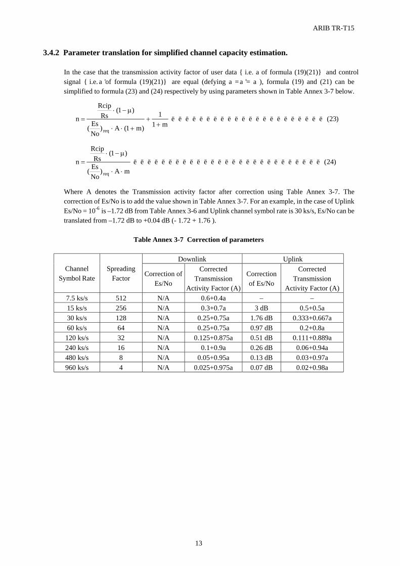
ARIB TR-T15
13
3.4.2 Parameter translation for simplified channel capacity estimation. In the case that the transmission activity factor of user data {i.e. a of formula (19)(21)} and control signal {i.e. 'a of formula (19)(21)} are equal (defying a = 'a = a ), formula (19) and (21) can be simplified to formula (23) and (24) respectively by using parameters shown in Table Annex 3-7 below.
)23(m1
1
)m1(A)NoEs(
)1(Rs
Rcip
nreq
LLLLLLLLLLLLLLLLLLLLLL+
++⋅⋅
µ−⋅=
)24(mA)
NoEs(
)1(Rs
Rcip
nreq
LLLLLLLLLLLLLLLLLLLLLLLLLLL⋅⋅
µ−⋅=
Where A denotes the Transmission activity factor after correction using Table Annex 3-7. The correction of Es/No is to add the value shown in Table Annex 3-7. For an example, in the case of Uplink Es/No = 10-6 is –1.72 dB from Table Annex 3-6 and Uplink channel symbol rate is 30 ks/s, Es/No can be translated from –1.72 dB to +0.04 dB (- 1.72 + 1.76 ).
Table Annex 3-7 Correction of parameters
Downlink Uplink
Channel Symbol Rate
Spreading Factor Correction of
Es/No
Corrected Transmission
Activity Factor (A)
Correction of Es/No
Corrected Transmission
Activity Factor (A) 7.5 ks/s 512 N/A 0.6+0.4a − − 15 ks/s 256 N/A 0.3+0.7a 3 dB 0.5+0.5a 30 ks/s 128 N/A 0.25+0.75a 1.76 dB 0.333+0.667a 60 ks/s 64 N/A 0.25+0.75a 0.97 dB 0.2+0.8a 120 ks/s 32 N/A 0.125+0.875a 0.51 dB 0.111+0.889a 240 ks/s 16 N/A 0.1+0.9a 0.26 dB 0.06+0.94a 480 ks/s 8 N/A 0.05+0.95a 0.13 dB 0.03+0.97a 960 ks/s 4 N/A 0.025+0.975a 0.07 dB 0.02+0.98a
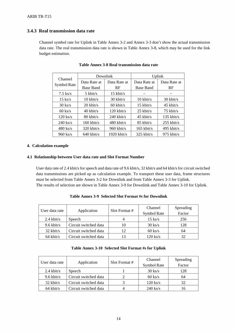
ARIB TR-T15
14
3.4.3 Real transmission data rate
Channel symbol rate for Uplink in Table Annex 3-2 and Annex 3-3 don’t show the actual transmission data rate. The real transmission data rate is shown in Table Annex 3-8, which may be used for the link budget estimation.
Table Annex 3-8 Real transmission data rate
Downlink Uplink
Channel Symbol Rate Data Rate at
Base Band Data Rate at
RF Data Rate at Base Band
Data Rate at RF
7.5 ks/s 5 kbit/s 15 kbit/s − − 15 ks/s 10 kbit/s 30 kbit/s 10 kbit/s 30 kbit/s 30 ks/s 20 kbit/s 60 kbit/s 15 kbit/s 45 kbit/s 60 ks/s 40 kbit/s 120 kbit/s 25 kbit/s 75 kbit/s
120 ks/s 80 kbit/s 240 kbit/s 45 kbit/s 135 kbit/s 240 ks/s 160 kbit/s 480 kbit/s 85 kbit/s 255 kbit/s 480 ks/s 320 kbit/s 960 kbit/s 165 kbit/s 495 kbit/s 960 ks/s 640 kbit/s 1920 kbit/s 325 kbit/s 975 kbit/s
4. Calculation example 4.1 Relationship between User data rate and Slot Format Number
User data rate of 2.4 kbit/s for speech and data rate of 9.6 kbit/s, 32 kbit/s and 64 kbit/s for circuit switched data transmissions are picked up as calculation example. To transport these user data, frame structures must be selected from Table Annex 3-2 for Downlink and from Table Annex 3-3 for Uplink. The results of selection are shown in Table Annex 3-9 for Downlink and Table Annex 3-10 for Uplink.
Table Annex 3-9 Selected Slot Format #s for Downlink
User data rate Application Slot Format # Channel
Symbol Rate Spreading
Factor 2.4 kbit/s Speech 4 15 ks/s 256 9.6 kbit/s Circuit switched data 10 30 ks/s 128 32 kbit/s Circuit switched data 12 60 ks/s 64 64 kbit/s Circuit switched data 13 120 ks/s 32
Table Annex 3-10 Selected Slot Format #s for Uplink
User data rate Application Slot Format # Channel
Symbol Rate Spreading
Factor 2.4 kbit/s Speech 1 30 ks/s 128 9.6 kbit/s Circuit switched data 2 60 ks/s 64 32 kbit/s Circuit switched data 3 120 ks/s 32 64 kbit/s Circuit switched data 4 240 ks/s 16
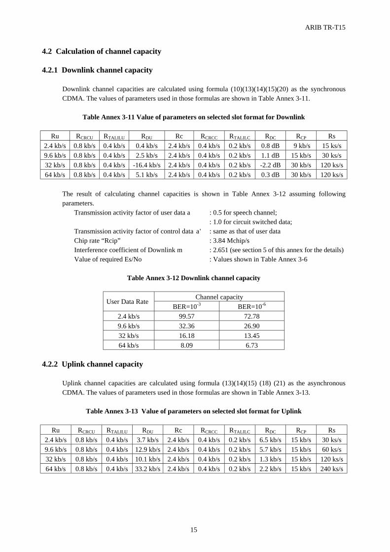
ARIB TR-T15
15
4.2 Calculation of channel capacity 4.2.1 Downlink channel capacity
Downlink channel capacities are calculated using formula (10)(13)(14)(15)(20) as the synchronous CDMA. The values of parameters used in those formulas are shown in Table Annex 3-11.
Table Annex 3-11 Value of parameters on selected slot format for Downlink
Ru RCRCU RTALILU RDU Rc RCRCC RTALILC RDC RCP Rs
2.4 kb/s 0.8 kb/s 0.4 kb/s 0.4 kb/s 2.4 kb/s 0.4 kb/s 0.2 kb/s 0.8 dB 9 kb/s 15 ks/s 9.6 kb/s 0.8 kb/s 0.4 kb/s 2.5 kb/s 2.4 kb/s 0.4 kb/s 0.2 kb/s 1.1 dB 15 kb/s 30 ks/s 32 kb/s 0.8 kb/s 0.4 kb/s -16.4 kb/s 2.4 kb/s 0.4 kb/s 0.2 kb/s -2.2 dB 30 kb/s 120 ks/s 64 kb/s 0.8 kb/s 0.4 kb/s 5.1 kb/s 2.4 kb/s 0.4 kb/s 0.2 kb/s 0.3 dB 30 kb/s 120 ks/s
The result of calculating channel capacities is shown in Table Annex 3-12 assuming following parameters.
Transmission activity factor of user data a : 0.5 for speech channel; : 1.0 for circuit switched data; Transmission activity factor of control data 'a : same as that of user data Chip rate “Rcip” : 3.84 Mchip/s Interference coefficient of Downlink m : 2.651 (see section 5 of this annex for the details) Value of required Es/No : Values shown in Table Annex 3-6
Table Annex 3-12 Downlink channel capacity
Channel capacity
User Data Rate BER=10-3 BER=10-6
2.4 kb/s 99.57 72.78 9.6 kb/s 32.36 26.90 32 kb/s 16.18 13.45 64 kb/s 8.09 6.73
4.2.2 Uplink channel capacity
Uplink channel capacities are calculated using formula (13)(14)(15) (18) (21) as the asynchronous CDMA. The values of parameters used in those formulas are shown in Table Annex 3-13.
Table Annex 3-13 Value of parameters on selected slot format for Uplink
Ru RCRCU RTALILU RDU Rc RCRCC RTALILC RDC RCP Rs
2.4 kb/s 0.8 kb/s 0.4 kb/s 3.7 kb/s 2.4 kb/s 0.4 kb/s 0.2 kb/s 6.5 kb/s 15 kb/s 30 ks/s 9.6 kb/s 0.8 kb/s 0.4 kb/s 12.9 kb/s 2.4 kb/s 0.4 kb/s 0.2 kb/s 5.7 kb/s 15 kb/s 60 ks/s 32 kb/s 0.8 kb/s 0.4 kb/s 10.1 kb/s 2.4 kb/s 0.4 kb/s 0.2 kb/s 1.3 kb/s 15 kb/s 120 ks/s 64 kb/s 0.8 kb/s 0.4 kb/s 33.2 kb/s 2.4 kb/s 0.4 kb/s 0.2 kb/s 2.2 kb/s 15 kb/s 240 ks/s
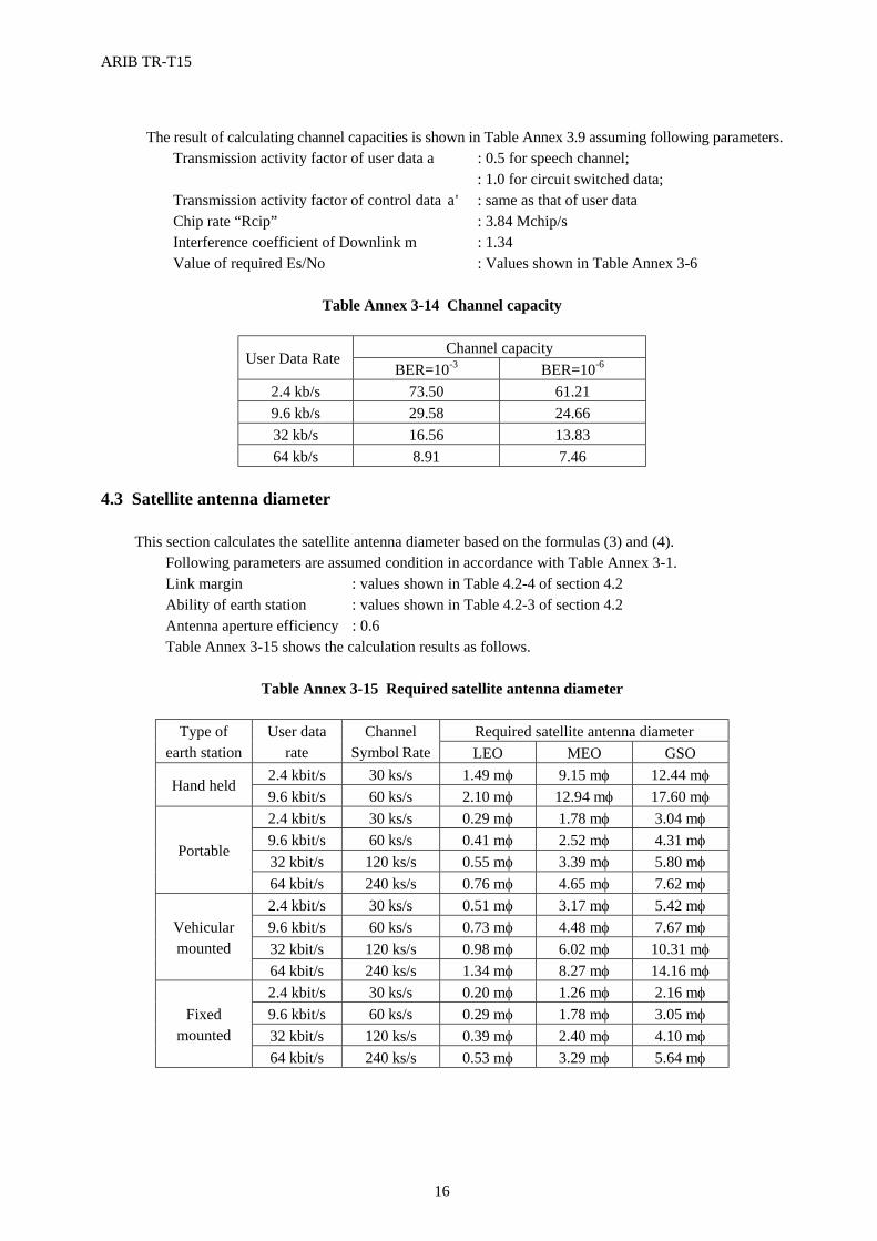
ARIB TR-T15
16
The result of calculating channel capacities is shown in Table Annex 3.9 assuming following parameters.
Transmission activity factor of user data a : 0.5 for speech channel; : 1.0 for circuit switched data; Transmission activity factor of control data 'a : same as that of user data Chip rate “Rcip” : 3.84 Mchip/s Interference coefficient of Downlink m : 1.34 Value of required Es/No : Values shown in Table Annex 3-6
Table Annex 3-14 Channel capacity
Channel capacity
User Data Rate BER=10-3 BER=10-6
2.4 kb/s 73.50 61.21 9.6 kb/s 29.58 24.66 32 kb/s 16.56 13.83 64 kb/s 8.91 7.46
4.3 Satellite antenna diameter
This section calculates the satellite antenna diameter based on the formulas (3) and (4). Following parameters are assumed condition in accordance with Table Annex 3-1. Link margin : values shown in Table 4.2-4 of section 4.2 Ability of earth station : values shown in Table 4.2-3 of section 4.2 Antenna aperture efficiency : 0.6 Table Annex 3-15 shows the calculation results as follows.
Table Annex 3-15 Required satellite antenna diameter
Required satellite antenna diameter Type of
earth station User data
rate Channel
Symbol Rate LEO MEO GSO 2.4 kbit/s 30 ks/s 1.49 mφ 9.15 mφ 12.44 mφ
Hand held 9.6 kbit/s 60 ks/s 2.10 mφ 12.94 mφ 17.60 mφ 2.4 kbit/s 30 ks/s 0.29 mφ 1.78 mφ 3.04 mφ 9.6 kbit/s 60 ks/s 0.41 mφ 2.52 mφ 4.31 mφ 32 kbit/s 120 ks/s 0.55 mφ 3.39 mφ 5.80 mφ
Portable
64 kbit/s 240 ks/s 0.76 mφ 4.65 mφ 7.62 mφ 2.4 kbit/s 30 ks/s 0.51 mφ 3.17 mφ 5.42 mφ 9.6 kbit/s 60 ks/s 0.73 mφ 4.48 mφ 7.67 mφ 32 kbit/s 120 ks/s 0.98 mφ 6.02 mφ 10.31 mφ
Vehicular mounted
64 kbit/s 240 ks/s 1.34 mφ 8.27 mφ 14.16 mφ 2.4 kbit/s 30 ks/s 0.20 mφ 1.26 mφ 2.16 mφ 9.6 kbit/s 60 ks/s 0.29 mφ 1.78 mφ 3.05 mφ 32 kbit/s 120 ks/s 0.39 mφ 2.40 mφ 4.10 mφ
Fixed mounted
64 kbit/s 240 ks/s 0.53 mφ 3.29 mφ 5.64 mφ
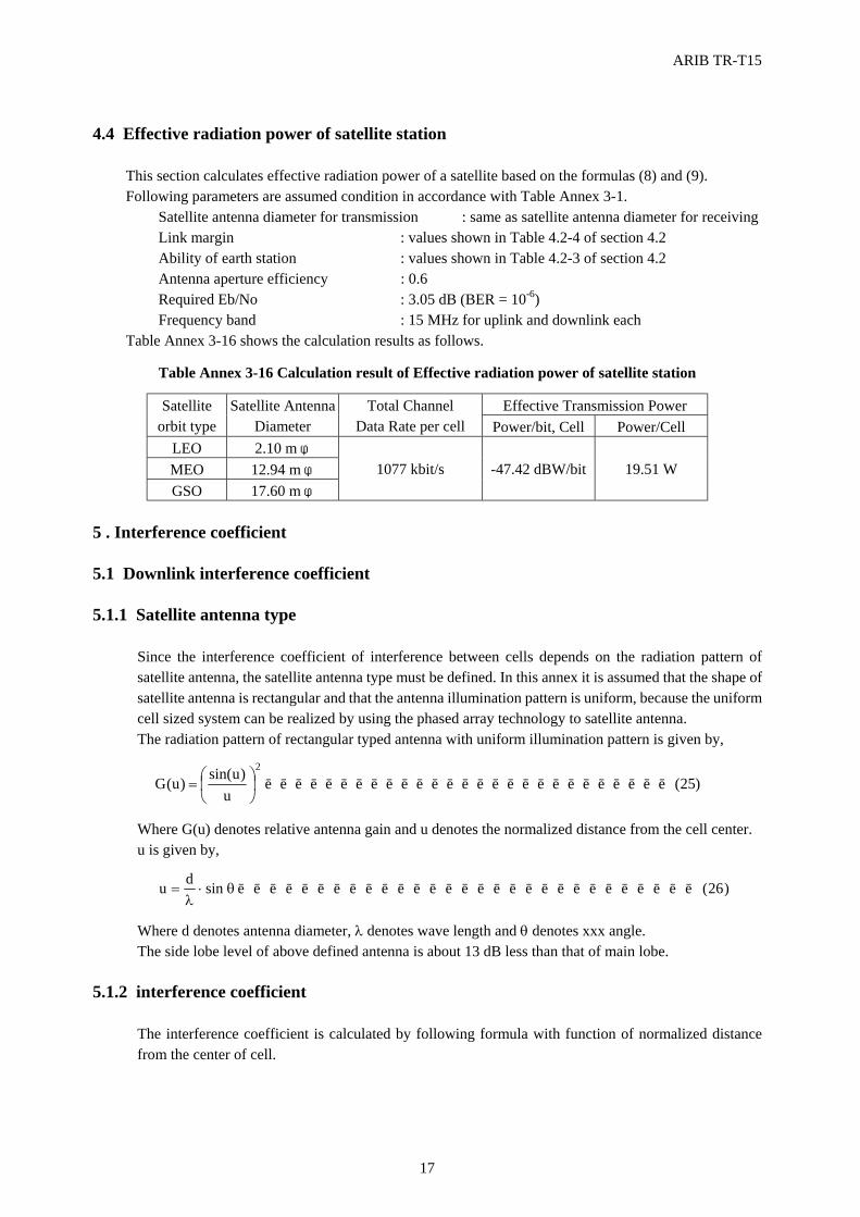
ARIB TR-T15
17
4.4 Effective radiation power of satellite station
This section calculates effective radiation power of a satellite based on the formulas (8) and (9). Following parameters are assumed condition in accordance with Table Annex 3-1.
Satellite antenna diameter for transmission : same as satellite antenna diameter for receiving Link margin : values shown in Table 4.2-4 of section 4.2 Ability of earth station : values shown in Table 4.2-3 of section 4.2 Antenna aperture efficiency : 0.6 Required Eb/No : 3.05 dB (BER = 10-6) Frequency band : 15 MHz for uplink and downlink each
Table Annex 3-16 shows the calculation results as follows.
Table Annex 3-16 Calculation result of Effective radiation power of satellite station
Effective Transmission Power Satellite orbit type
Satellite Antenna Diameter
Total Channel Data Rate per cell Power/bit, Cell Power/Cell
LEO 2.10 m φ MEO 12.94 m φ GSO 17.60 m φ
1077 kbit/s -47.42 dBW/bit 19.51 W
5 . Interference coefficient 5.1 Downlink interference coefficient 5.1.1 Satellite antenna type
Since the interference coefficient of interference between cells depends on the radiation pattern of satellite antenna, the satellite antenna type must be defined. In this annex it is assumed that the shape of satellite antenna is rectangular and that the antenna illumination pattern is uniform, because the uniform cell sized system can be realized by using the phased array technology to satellite antenna. The radiation pattern of rectangular typed antenna with uniform illumination pattern is given by,
)25(u
)usin()u(G2
LLLLLLLLLLLLLLLLLLLLLLLLLLL
=
Where G(u) denotes relative antenna gain and u denotes the normalized distance from the cell center. u is given by,
)26(sindu LLLLLLLLLLLLLLLLLLLLLLLLLLLLLθ⋅λ
= Where d denotes antenna diameter, λ denotes wave length and θ denotes xxx angle. The side lobe level of above defined antenna is about 13 dB less than that of main lobe.
5.1.2 interference coefficient
The interference coefficient is calculated by following formula with function of normalized distance from the center of cell.
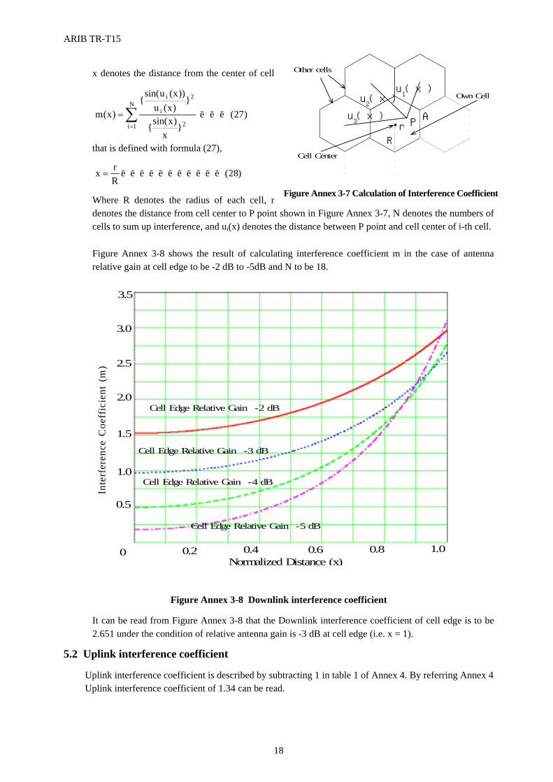
ARIB TR-T15
18
������������������������������������������������������������������������������������������������������������������������������������������������������������������������������
������������������������������������������������������������������������������������������������������������������������������������������������������������������������������
������������������������������������������������������������������������������������������������������������������������������������������������������������������������������
������������������������������������������������������������������������������������������������������������������������������������������������������������������������������
�����������������������������������������������������������������������������������������������������������������������������������������������������������������������������������������������������������
�����������������������������������������������������������������������������������������������������������������������������������������������������������������������������������������������������������
�����������������������������������������������������������������������������������������������������������������������������������������������������������������������������������������������������������
�����������������������������������������������������������������������������������������������������������������������������������������������������������������������������������������������������������
�����������������������������������������������������������������������������������������������������������������������������������������������������������������������������������������������������������
�����������������������������������������������������������������������������������������������������������������������������������������������������������������������������������������������������������
Other cells
Cell Center
A
u1(x)
u2(x)
u3(x)
PrR
Own Cell
Figure A3.7 Calculaion of Interference Coefficient
x denotes the distance from the center of cell
that is defined with formula (27),
Where R denotes the radius of each cell, r denotes the distance from cell center to P point shown in Figure Annex 3-7, N denotes the numbers of cells to sum up interference, and ui(x) denotes the distance between P point and cell center of i-th cell. Figure Annex 3-8 shows the result of calculating interference coefficient m in the case of antenna relative gain at cell edge to be -2 dB to -5dB and N to be 18.
Figure Annex 3-8 Downlink interference coefficient It can be read from Figure Annex 3-8 that the Downlink interference coefficient of cell edge is to be 2.651 under the condition of relative antenna gain is -3 dB at cell edge (i.e. x = 1).
5.2 Uplink interference coefficient
Uplink interference coefficient is described by subtracting 1 in table 1 of Annex 4. By referring Annex 4 Uplink interference coefficient of 1.34 can be read.
Normalized Distance (x)
Inte
rfer
ence
Coe
ffic
ient
(m)
Cell Edge Relative Gain -2 dB
Cell Edge Relative Gain -3 dB
Cell Edge Relative Gain -4 dB
Cell Edge Relative Gain -5 dB
0 0.2 0.4 0.6 0.8 1.0
0.5
1.0
1.5
2.0
2.5
3.0
3.5
)28(Rrx LLLLLLLLLLL=
)27(}
x)xsin({
})x(u
))x(usin({
)x(mN
1i 2
2
i
i
LLL∑=
=
Figure Annex 3-7 Calculation of Interference Coefficient
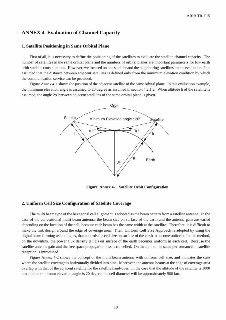
ARIB TR-T15
19
ANNEX 4 Evaluation of Channel Capacity 1. Satellite Positioning in Same Orbital Plane
First of all, it is necessary to define the positioning of the satellites to evaluate the satellite channel capacity. The number of satellites in the same orbital plane and the numbers of orbital planes are important parameters for low earth orbit satellite constellations. However, we focused on one satellite and the neighboring satellites in this evaluation. It is assumed that the distance between adjacent satellites is defined only from the minimum elevation condition by which the communication service can be provided.
Figure Annex 4-1 shows the position of the adjacent satellite of the same orbital plane. In this evaluation example, the minimum elevation angle is assumed to 20 degree as assumed in section 4.2.1.2. When altitude h of the satellite is assumed, the angle 2α between adjacent satellites of the same orbital plane is given.
Figure Annex 4-1 Satellite Orbit Configuration
2. Uniform Cell Size Configuration of Satellite Coverage
The multi beam type of the hexagonal cell alignment is adopted as the beam pattern from a satellite antenna. In the case of the conventional multi-beam antenna, the beam size on surface of the earth and the antenna gain are varied depending on the location of the cell, because each beam has the same width at the satellite. Therefore, it is difficult to make the link design around the edge of coverage area. Then, Uniform Cell Size Approach is adopted by using the digital beam forming technologies, that controls the cell size on surface of the earth to become uniform. In this method, on the downlink, the power flux density (PFD) on surface of the earth becomes uniform in each cell. Because the satellite antenna gain and the free space propagation loss is cancelled. On the uplink, the same performance of satellite reception is introduced.
Figure Annex 4-2 shows the concept of the multi beam antenna with uniform cell size, and indicates the case where the satellite coverage is horizontally divided into nine. Moreover, the antenna beams at the edge of coverage area overlap with that of the adjacent satellite for the satellite hand-over. In the case that the altitude of the satellite is 1000 km and the minimum elevation angle is 20 degree, the cell diameter will be approximately 500 km.
R
h
SatelliteMinimum Elevation angle : 20°
α
Satellite
h20°20°
Orbit
Earth

ARIB TR-T15
20
Figure Annex 4-2 Uniform Cell Size Configuration
3. Interference Evaluation 3.1 Evaluation of Cross-Correlation Interference for the Satellite Nadir Cell 3.1.1 Estimated Area for Interference Evaluation
Figure Annex 4-3 shows the area to evaluate the cross-correlation interference into the satellite nadir cell. In this case, the satellites move from the bottom to the top on the figure with three parallel orbits by the triangular formations is assumed. Therefore, the coverage shape of each satellite is hexagon.
Now that the amount of the interference is calculated on the evaluated cell which is located at the satellite nadir as shown on figure Annex 4-3. Since there are cells around the satellite symmetrically, the amount of interference from surrounding cells is obtained by multiplying four to the interference area with the back slashed line on that figure.
Figure Annex 4-3 Evaluated Area of Cross-Correlation Interference for Satellite Nadir Cell
R
Satellite
d ddddd
d
d : Cell Diameter= 500km (h=1000km)
Sat(l,m)
Sat(l,m-1)
Sat(l+1,m)
Sat(l,m+1)
Sat(l+1,m-1)Sat(l-1,m)
Sat(l-1,m+1)
Sat(l,m) : m-th Satellite at l-th orbit
Evaluated Cell( Satellite Nadir Cell )
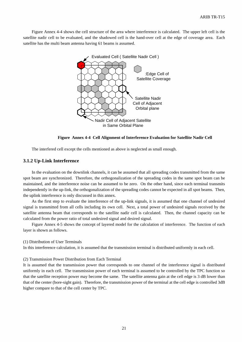
ARIB TR-T15
21
Figure Annex 4-4 shows the cell structure of the area where interference is calculated. The upper left cell is the satellite nadir cell to be evaluated, and the shadowed cell is the hand-over cell at the edge of coverage area. Each satellite has the multi beam antenna having 61 beams is assumed.
Figure Annex 4-4 Cell Alignment of Interference Evaluation for Satellite Nadir Cell
The interfered cell except the cells mentioned as above is neglected as small enough.
3.1.2 Up-Link Interference
In the evaluation on the downlink channels, it can be assumed that all spreading codes transmitted from the same spot beam are synchronized. Therefore, the orthogonalization of the spreading codes in the same spot beam can be maintained, and the interference noise can be assumed to be zero. On the other hand, since each terminal transmits independently in the up-link, the orthogonalization of the spreading codes cannot be expected in all spot beams. Then, the uplink interference is only discussed in this annex.
As the first step to evaluate the interference of the up-link signals, it is assumed that one channel of undesired signal is transmitted from all cells including its own cell. Next, a total power of undesired signals received by the satellite antenna beam that corresponds to the satellite nadir cell is calculated. Then, the channel capacity can be calculated from the power ratio of total undesired signal and desired signal.
Figure Annex 4-5 shows the concept of layered model for the calculation of interference. The function of each layer is shown as follows.
(1) Distribution of User Terminals In this interference calculation, it is assumed that the transmission terminal is distributed uniformly in each cell. (2) Transmission Power Distribution from Each Terminal It is assumed that the transmission power that corresponds to one channel of the interference signal is distributed uniformly in each cell. The transmission power of each terminal is assumed to be controlled by the TPC function so that the satellite reception power may become the same. The satellite antenna gain at the cell edge is 3 dB lower than that of the center (bore-sight gain). Therefore, the transmission power of the terminal at the cell edge is controlled 3dB higher compare to that of the cell center by TPC.
Satellite NadirCell of Adjacent
Orbital plane
Nadir Cell of Adjacent Satellitein Same Orbital Plane
:Edge Cell ofSatellite Coverage
Evaluated Cell ( Satellite Nadir Cell )
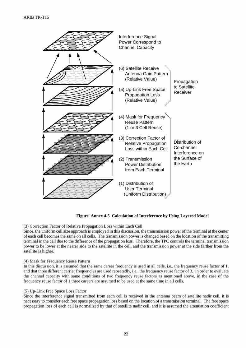
ARIB TR-T15
22
Figure Annex 4-5 Calculation of Interference by Using Layered Model
(3) Correction Factor of Relative Propagation Loss within Each Cell Since, the uniform cell size approach is employed in this discussion, the transmission power of the terminal at the center of each cell becomes the same on all cells. The transmission power is changed based on the location of the transmitting terminal in the cell due to the difference of the propagation loss. Therefore, the TPC controls the terminal transmission power to be lower at the nearer side to the satellite in the cell, and the transmission power at the side farther from the satellite is higher. (4) Mask for Frequency Reuse Pattern In this discussion, it is assumed that the same career frequency is used in all cells, i.e., the frequency reuse factor of 1, and that three different carrier frequencies are used repeatedly, i.e., the frequency reuse factor of 3. In order to evaluate the channel capacity with same conditions of two frequency reuse factors as mentioned above, in the case of the frequency reuse factor of 1 three careers are assumed to be used at the same time in all cells. (5) Up-Link Free Space Loss Factor Since the interference signal transmitted from each cell is received in the antenna beam of satellite nadir cell, it is necessary to consider each free space propagation loss based on the location of a transmission terminal. The free space propagation loss of each cell is normalized by that of satellite nadir cell, and it is assumed the attenuation coefficient
(6) Satellite Receive Antenna Gain Pattern (Relative Value)
(5) Up-Link Free Space Propagation Loss (Relative Value)
(4) Mask for Frequency Reuse Pattern (1 or 3 Cell Reuse)
(3) Correction Factor of Relative Propagation Loss within Each Cell
(2) Transmission Power Distribution from Each Terminal
(1) Distribution of User Terminal (Uniform Distribution)
Distribution ofCo-channelInterference onthe Surface ofthe Earth
Propagationto SatelliteReceiver
Interference SignalPower Correspond toChannel Capacity
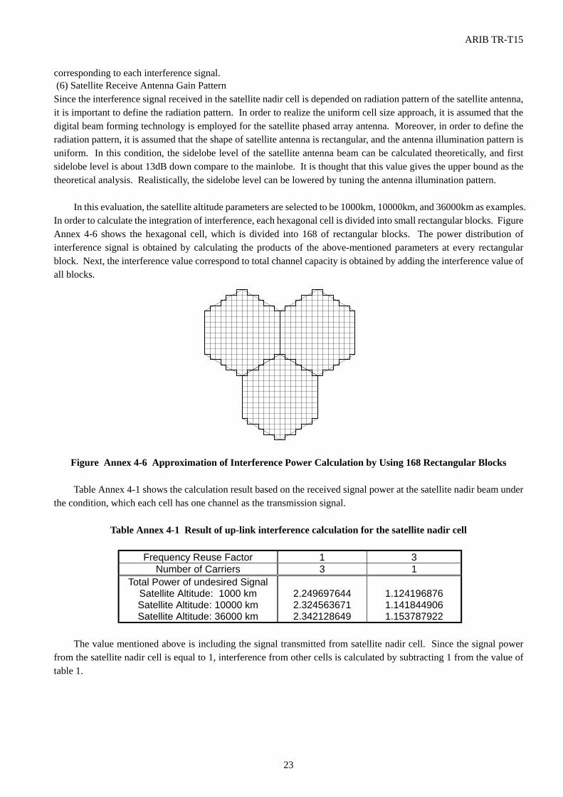
ARIB TR-T15
23
corresponding to each interference signal. (6) Satellite Receive Antenna Gain Pattern Since the interference signal received in the satellite nadir cell is depended on radiation pattern of the satellite antenna, it is important to define the radiation pattern. In order to realize the uniform cell size approach, it is assumed that the digital beam forming technology is employed for the satellite phased array antenna. Moreover, in order to define the radiation pattern, it is assumed that the shape of satellite antenna is rectangular, and the antenna illumination pattern is uniform. In this condition, the sidelobe level of the satellite antenna beam can be calculated theoretically, and first sidelobe level is about 13dB down compare to the mainlobe. It is thought that this value gives the upper bound as the theoretical analysis. Realistically, the sidelobe level can be lowered by tuning the antenna illumination pattern.
In this evaluation, the satellite altitude parameters are selected to be 1000km, 10000km, and 36000km as examples. In order to calculate the integration of interference, each hexagonal cell is divided into small rectangular blocks. Figure Annex 4-6 shows the hexagonal cell, which is divided into 168 of rectangular blocks. The power distribution of interference signal is obtained by calculating the products of the above-mentioned parameters at every rectangular block. Next, the interference value correspond to total channel capacity is obtained by adding the interference value of all blocks.
Figure Annex 4-6 Approximation of Interference Power Calculation by Using 168 Rectangular Blocks Table Annex 4-1 shows the calculation result based on the received signal power at the satellite nadir beam under
the condition, which each cell has one channel as the transmission signal.
Table Annex 4-1 Result of up-link interference calculation for the satellite nadir cell
Frequency Reuse Factor 1 3 Number of Carriers 3 1
Total Power of undesired Signal Satellite Altitude: 1000 km Satellite Altitude: 10000 km Satellite Altitude: 36000 km
2.249697644 2.324563671 2.342128649
1.124196876 1.141844906 1.153787922
The value mentioned above is including the signal transmitted from satellite nadir cell. Since the signal power
from the satellite nadir cell is equal to 1, interference from other cells is calculated by subtracting 1 from the value of table 1.
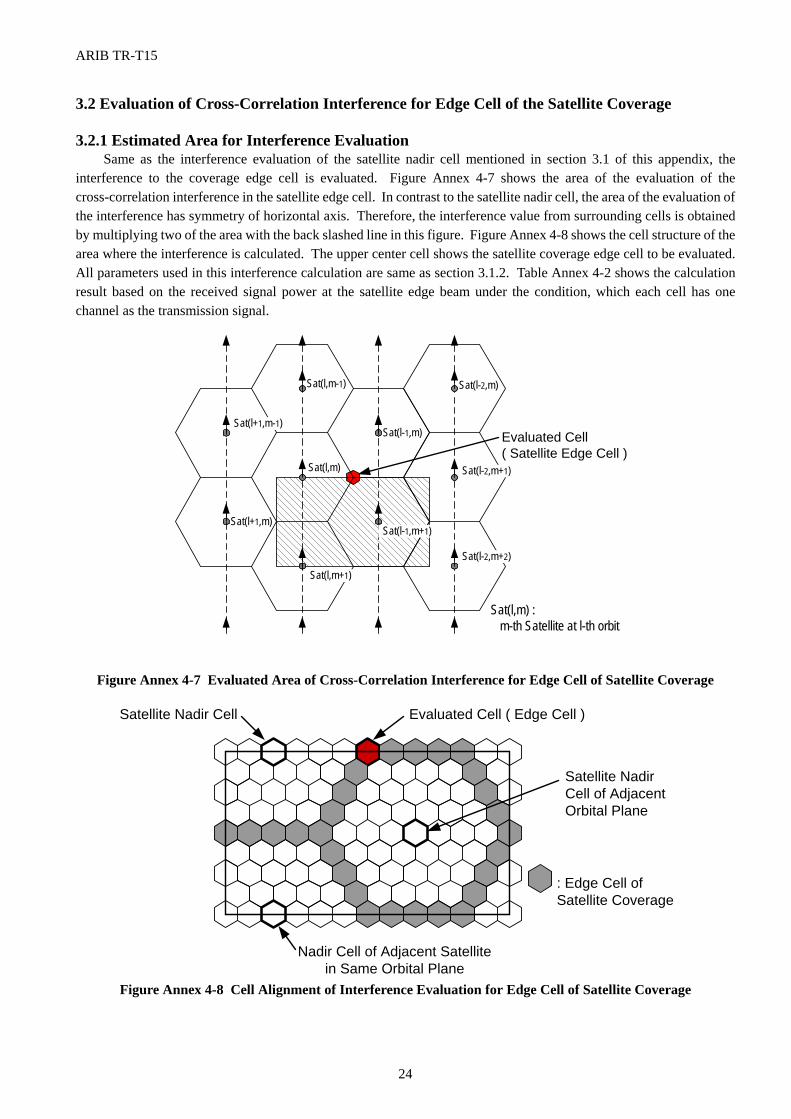
ARIB TR-T15
24
3.2 Evaluation of Cross-Correlation Interference for Edge Cell of the Satellite Coverage 3.2.1 Estimated Area for Interference Evaluation
Same as the interference evaluation of the satellite nadir cell mentioned in section 3.1 of this appendix, the interference to the coverage edge cell is evaluated. Figure Annex 4-7 shows the area of the evaluation of the cross-correlation interference in the satellite edge cell. In contrast to the satellite nadir cell, the area of the evaluation of the interference has symmetry of horizontal axis. Therefore, the interference value from surrounding cells is obtained by multiplying two of the area with the back slashed line in this figure. Figure Annex 4-8 shows the cell structure of the area where the interference is calculated. The upper center cell shows the satellite coverage edge cell to be evaluated. All parameters used in this interference calculation are same as section 3.1.2. Table Annex 4-2 shows the calculation result based on the received signal power at the satellite edge beam under the condition, which each cell has one channel as the transmission signal.
Figure Annex 4-7 Evaluated Area of Cross-Correlation Interference for Edge Cell of Satellite Coverage
Figure Annex 4-8 Cell Alignment of Interference Evaluation for Edge Cell of Satellite Coverage
Sat(l+1,m-1)
Sat(l+1,m)
Sat(l,m-1)
Sat(l,m)
Sat(l,m+1)
Sat(l-1,m)
Sat(l-1,m+1)
Sat(l,m) : m-th Satellite at l-th orbit
Evaluated Cell( Satellite Edge Cell )
Sat(l-2,m)
Sat(l-2,m+1)
Sat(l-2,m+2)
Satellite Nadir Cell
: Edge Cell ofSatellite Coverage
Evaluated Cell ( Edge Cell )
Satellite NadirCell of AdjacentOrbital Plane
Nadir Cell of Adjacent Satellitein Same Orbital Plane
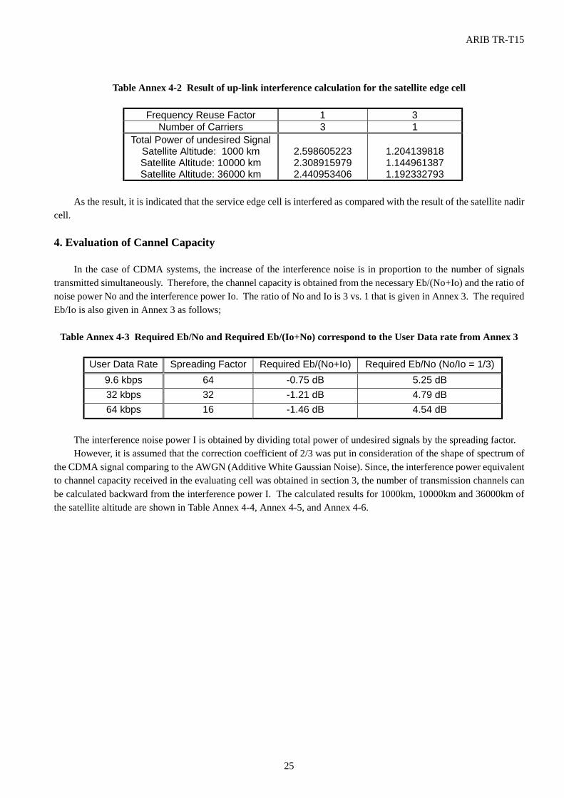
ARIB TR-T15
25
Table Annex 4-2 Result of up-link interference calculation for the satellite edge cell
Frequency Reuse Factor 1 3
Number of Carriers 3 1 Total Power of undesired Signal
Satellite Altitude: 1000 km Satellite Altitude: 10000 km Satellite Altitude: 36000 km
2.598605223 2.308915979 2.440953406
1.204139818 1.144961387 1.192332793
As the result, it is indicated that the service edge cell is interfered as compared with the result of the satellite nadir
cell.
4. Evaluation of Cannel Capacity
In the case of CDMA systems, the increase of the interference noise is in proportion to the number of signals transmitted simultaneously. Therefore, the channel capacity is obtained from the necessary Eb/(No+Io) and the ratio of noise power No and the interference power Io. The ratio of No and Io is 3 vs. 1 that is given in Annex 3. The required Eb/Io is also given in Annex 3 as follows;
Table Annex 4-3 Required Eb/No and Required Eb/(Io+No) correspond to the User Data rate from Annex 3
User Data Rate Spreading Factor Required Eb/(No+Io) Required Eb/No (No/Io = 1/3)
9.6 kbps 64 -0.75 dB 5.25 dB 32 kbps 32 -1.21 dB 4.79 dB 64 kbps 16 -1.46 dB 4.54 dB
The interference noise power I is obtained by dividing total power of undesired signals by the spreading factor. However, it is assumed that the correction coefficient of 2/3 was put in consideration of the shape of spectrum of
the CDMA signal comparing to the AWGN (Additive White Gaussian Noise). Since, the interference power equivalent to channel capacity received in the evaluating cell was obtained in section 3, the number of transmission channels can be calculated backward from the interference power I. The calculated results for 1000km, 10000km and 36000km of the satellite altitude are shown in Table Annex 4-4, Annex 4-5, and Annex 4-6.
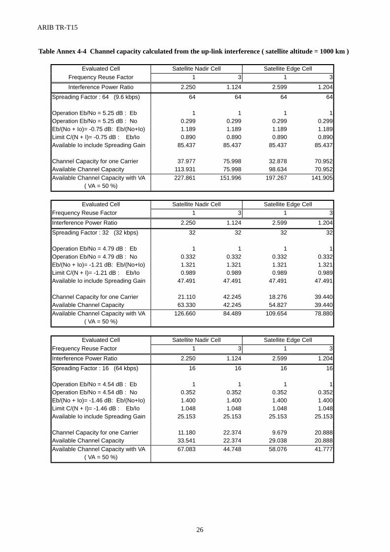
ARIB TR-T15
26
Table Annex 4-4 Channel capacity calculated from the up-link interference ( satellite altitude = 1000 km )
Evaluated Cell Satellite Nadir Cell Satellite Edge Cell
Frequency Reuse Factor 1 3 1 3
Interference Power Ratio 2.250 1.124 2.599 1.204
Spreading Factor : 64 (9.6 kbps) 64 64 64 64
Operation Eb/No = 5.25 dB : Eb 1 1 1 1
Operation Eb/No = 5.25 dB : No 0.299 0.299 0.299 0.299
Eb/(No + Io)= -0.75 dB: Eb/(No+Io) 1.189 1.189 1.189 1.189
Limit C/(N + I)= -0.75 dB : Eb/Io 0.890 0.890 0.890 0.890
Available Io include Spreading Gain 85.437 85.437 85.437 85.437
Channel Capacity for one Carrier 37.977 75.998 32.878 70.952
Available Channel Capacity 113.931 75.998 98.634 70.952
Available Channel Capacity with VA 227.861 151.996 197.267 141.905
( VA = 50 %)
Evaluated Cell Satellite Nadir Cell Satellite Edge Cell
Frequency Reuse Factor 1 3 1 3
Interference Power Ratio 2.250 1.124 2.599 1.204
Spreading Factor : 32 (32 kbps) 32 32 32 32
Operation Eb/No = 4.79 dB : Eb 1 1 1 1
Operation Eb/No = 4.79 dB : No 0.332 0.332 0.332 0.332
Eb/(No + Io)= -1.21 dB: Eb/(No+Io) 1.321 1.321 1.321 1.321
Limit C/(N + I)= -1.21 dB : Eb/Io 0.989 0.989 0.989 0.989
Available Io include Spreading Gain 47.491 47.491 47.491 47.491
Channel Capacity for one Carrier 21.110 42.245 18.276 39.440
Available Channel Capacity 63.330 42.245 54.827 39.440
Available Channel Capacity with VA 126.660 84.489 109.654 78.880
( VA = 50 %)
Evaluated Cell Satellite Nadir Cell Satellite Edge Cell
Frequency Reuse Factor 1 3 1 3
Interference Power Ratio 2.250 1.124 2.599 1.204
Spreading Factor : 16 (64 kbps) 16 16 16 16
Operation Eb/No = 4.54 dB : Eb 1 1 1 1
Operation Eb/No = 4.54 dB : No 0.352 0.352 0.352 0.352
Eb/(No + Io)= -1.46 dB: Eb/(No+Io) 1.400 1.400 1.400 1.400
Limit C/(N + I)= -1.46 dB : Eb/Io 1.048 1.048 1.048 1.048
Available Io include Spreading Gain 25.153 25.153 25.153 25.153
Channel Capacity for one Carrier 11.180 22.374 9.679 20.888
Available Channel Capacity 33.541 22.374 29.038 20.888
Available Channel Capacity with VA 67.083 44.748 58.076 41.777
( VA = 50 %)
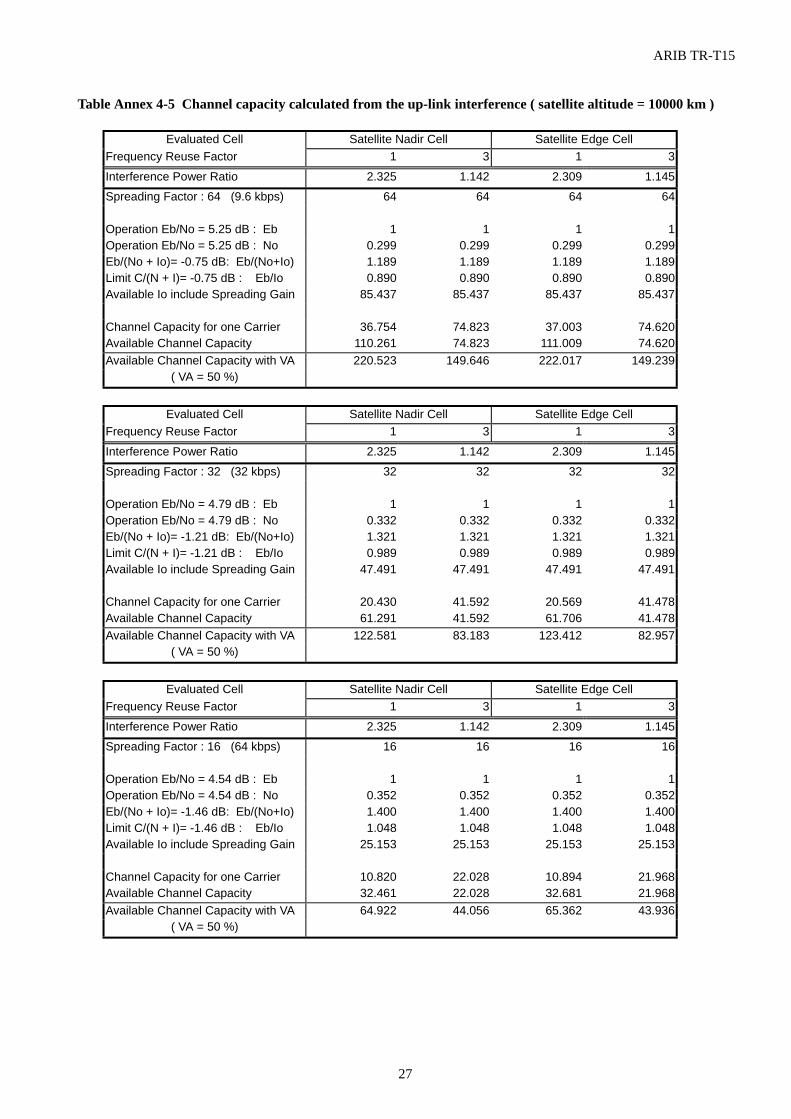
ARIB TR-T15
27
Table Annex 4-5 Channel capacity calculated from the up-link interference ( satellite altitude = 10000 km )
Evaluated Cell Satellite Nadir Cell Satellite Edge Cell
Frequency Reuse Factor 1 3 1 3
Interference Power Ratio 2.325 1.142 2.309 1.145
Spreading Factor : 64 (9.6 kbps) 64 64 64 64
Operation Eb/No = 5.25 dB : Eb 1 1 1 1
Operation Eb/No = 5.25 dB : No 0.299 0.299 0.299 0.299
Eb/(No + Io)= -0.75 dB: Eb/(No+Io) 1.189 1.189 1.189 1.189
Limit C/(N + I)= -0.75 dB : Eb/Io 0.890 0.890 0.890 0.890
Available Io include Spreading Gain 85.437 85.437 85.437 85.437
Channel Capacity for one Carrier 36.754 74.823 37.003 74.620
Available Channel Capacity 110.261 74.823 111.009 74.620
Available Channel Capacity with VA 220.523 149.646 222.017 149.239
( VA = 50 %)
Evaluated Cell Satellite Nadir Cell Satellite Edge Cell
Frequency Reuse Factor 1 3 1 3
Interference Power Ratio 2.325 1.142 2.309 1.145
Spreading Factor : 32 (32 kbps) 32 32 32 32
Operation Eb/No = 4.79 dB : Eb 1 1 1 1
Operation Eb/No = 4.79 dB : No 0.332 0.332 0.332 0.332
Eb/(No + Io)= -1.21 dB: Eb/(No+Io) 1.321 1.321 1.321 1.321
Limit C/(N + I)= -1.21 dB : Eb/Io 0.989 0.989 0.989 0.989
Available Io include Spreading Gain 47.491 47.491 47.491 47.491
Channel Capacity for one Carrier 20.430 41.592 20.569 41.478
Available Channel Capacity 61.291 41.592 61.706 41.478
Available Channel Capacity with VA 122.581 83.183 123.412 82.957
( VA = 50 %)
Evaluated Cell Satellite Nadir Cell Satellite Edge Cell
Frequency Reuse Factor 1 3 1 3
Interference Power Ratio 2.325 1.142 2.309 1.145
Spreading Factor : 16 (64 kbps) 16 16 16 16
Operation Eb/No = 4.54 dB : Eb 1 1 1 1
Operation Eb/No = 4.54 dB : No 0.352 0.352 0.352 0.352
Eb/(No + Io)= -1.46 dB: Eb/(No+Io) 1.400 1.400 1.400 1.400
Limit C/(N + I)= -1.46 dB : Eb/Io 1.048 1.048 1.048 1.048
Available Io include Spreading Gain 25.153 25.153 25.153 25.153
Channel Capacity for one Carrier 10.820 22.028 10.894 21.968
Available Channel Capacity 32.461 22.028 32.681 21.968
Available Channel Capacity with VA 64.922 44.056 65.362 43.936
( VA = 50 %)
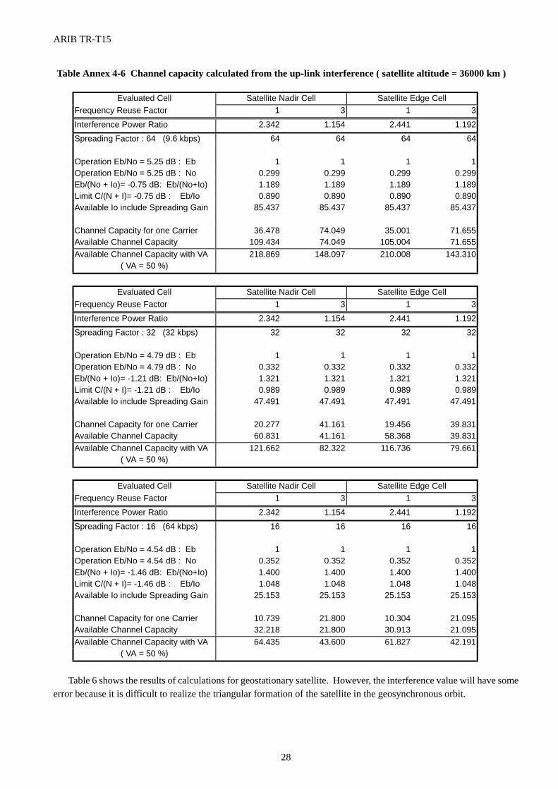
ARIB TR-T15
28
Table Annex 4-6 Channel capacity calculated from the up-link interference ( satellite altitude = 36000 km )
Evaluated Cell Satellite Nadir Cell Satellite Edge Cell
Frequency Reuse Factor 1 3 1 3
Interference Power Ratio 2.342 1.154 2.441 1.192
Spreading Factor : 64 (9.6 kbps) 64 64 64 64
Operation Eb/No = 5.25 dB : Eb 1 1 1 1
Operation Eb/No = 5.25 dB : No 0.299 0.299 0.299 0.299
Eb/(No + Io)= -0.75 dB: Eb/(No+Io) 1.189 1.189 1.189 1.189
Limit C/(N + I)= -0.75 dB : Eb/Io 0.890 0.890 0.890 0.890
Available Io include Spreading Gain 85.437 85.437 85.437 85.437
Channel Capacity for one Carrier 36.478 74.049 35.001 71.655
Available Channel Capacity 109.434 74.049 105.004 71.655
Available Channel Capacity with VA 218.869 148.097 210.008 143.310
( VA = 50 %)
Evaluated Cell Satellite Nadir Cell Satellite Edge Cell
Frequency Reuse Factor 1 3 1 3
Interference Power Ratio 2.342 1.154 2.441 1.192
Spreading Factor : 32 (32 kbps) 32 32 32 32
Operation Eb/No = 4.79 dB : Eb 1 1 1 1
Operation Eb/No = 4.79 dB : No 0.332 0.332 0.332 0.332
Eb/(No + Io)= -1.21 dB: Eb/(No+Io) 1.321 1.321 1.321 1.321
Limit C/(N + I)= -1.21 dB : Eb/Io 0.989 0.989 0.989 0.989
Available Io include Spreading Gain 47.491 47.491 47.491 47.491
Channel Capacity for one Carrier 20.277 41.161 19.456 39.831
Available Channel Capacity 60.831 41.161 58.368 39.831
Available Channel Capacity with VA 121.662 82.322 116.736 79.661
( VA = 50 %)
Evaluated Cell Satellite Nadir Cell Satellite Edge Cell
Frequency Reuse Factor 1 3 1 3
Interference Power Ratio 2.342 1.154 2.441 1.192
Spreading Factor : 16 (64 kbps) 16 16 16 16
Operation Eb/No = 4.54 dB : Eb 1 1 1 1
Operation Eb/No = 4.54 dB : No 0.352 0.352 0.352 0.352
Eb/(No + Io)= -1.46 dB: Eb/(No+Io) 1.400 1.400 1.400 1.400
Limit C/(N + I)= -1.46 dB : Eb/Io 1.048 1.048 1.048 1.048
Available Io include Spreading Gain 25.153 25.153 25.153 25.153
Channel Capacity for one Carrier 10.739 21.800 10.304 21.095
Available Channel Capacity 32.218 21.800 30.913 21.095
Available Channel Capacity with VA 64.435 43.600 61.827 42.191
( VA = 50 %)
Table 6 shows the results of calculations for geostationary satellite. However, the interference value will have some error because it is difficult to realize the triangular formation of the satellite in the geosynchronous orbit.
ARIB TR-T15
29
ANNEX 5 Summary of IMT-2000 Radio Transmission Technologies (RTTs) for Satellite Environment
In April 1997,the ITU-R Task Group 8/1 initiated a process for submission and subsequent evaluation of candidate radio transmission technologies (RTTs) to be used in the IMT-2000 radio interface by satellite as well as terrestrial mobile systems offering IMT-2000 services. During the process, 10 organizations submitted 15 satellite and terrestrial RTTs proposals to the ITU. In the proposals, 5 satellite RTTs were submitted on or before June 30, 1998 as follows;
1) SAT-CDMA for IMT-2000 RTT System Description, TTA/South Korea 2) Wideband CDMA Option for the Satellite Component of IMT-2000 "SW-CDMA", ESA 3) Wideband Hybrid CDMA/TDMA Option for the Satellite Component of IMT-2000 "SW-CTDMA", ESA 4) Submission of Candidate Satellite Radio Transmission Technology for IMT-2000 Radio Interface, ICO
Global Communications. 5) Inmarsat Proposal for a Satellite Radio Interface for IMT-2000 "Horizons RTT", Inmarsat.
In addition to the satellite proposals above, Iridium has submitted its proposal to the ITU. Satellite Working Group in ARIB has studied the 6 satellite RTTs that were submitted to the ITU and made a summary report in order to support the discussion in the ITU.
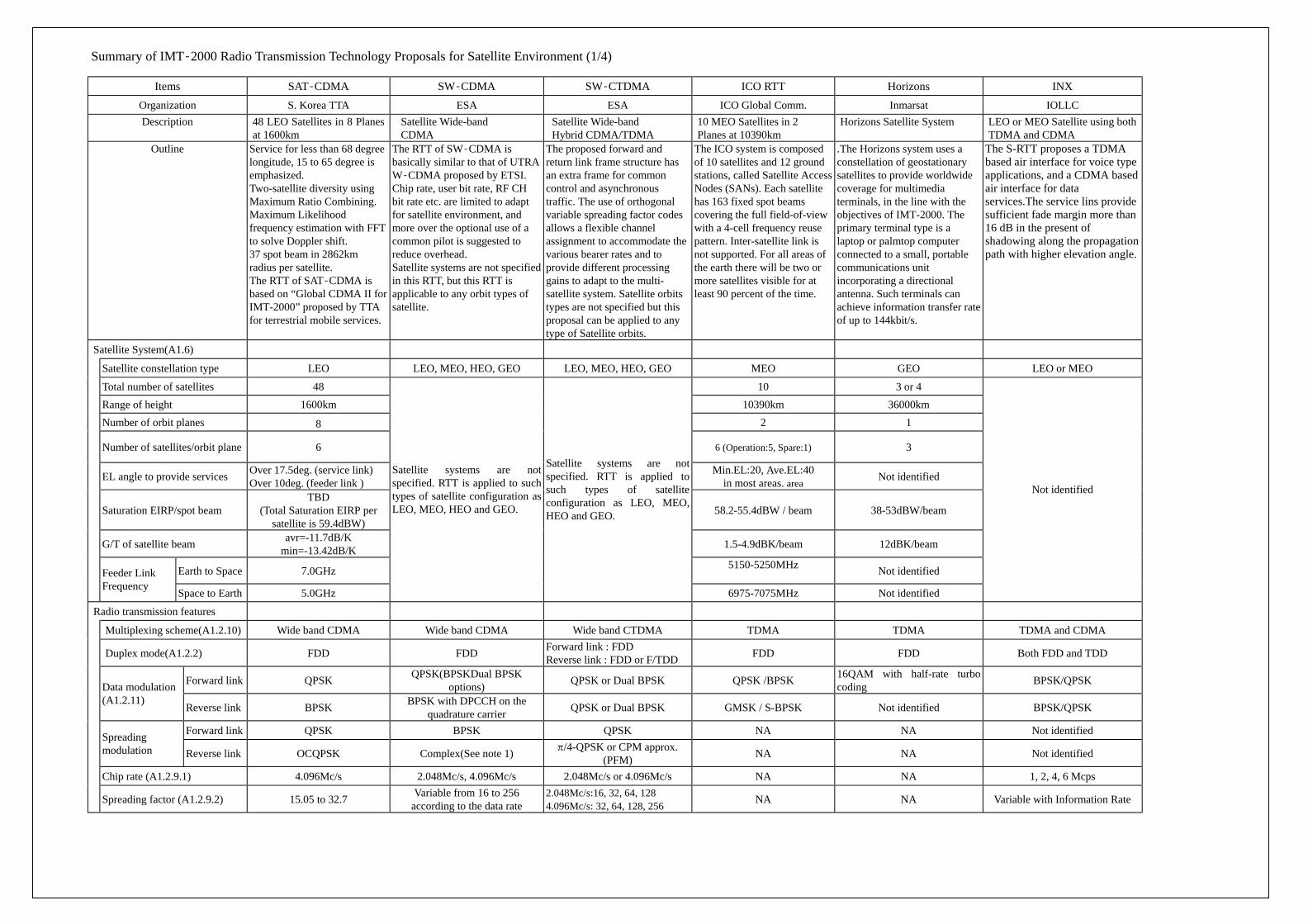
Summary of IMT-2000 Radio Transmission Technology Proposals for Satellite Environment (1/4)
Items SAT-CDMA SW-CDMA SW-CTDMA ICO RTT Horizons INX
Organization S. Korea TTA ESA ESA ICO Global Comm. Inmarsat IOLLC Description 48 LEO Satellites in 8 Planes
at 1600km Satellite Wide-band CDMA
Satellite Wide-band Hybrid CDMA/TDMA
10 MEO Satellites in 2 Planes at 10390km
Horizons Satellite System LEO or MEO Satellite using both TDMA and CDMA
Outline Service for less than 68 degree longitude, 15 to 65 degree is emphasized. Two-satellite diversity using Maximum Ratio Combining. Maximum Likelihood frequency estimation with FFT to solve Doppler shift. 37 spot beam in 2862km radius per satellite. The RTT of SAT-CDMA is based on “Global CDMA II for IMT-2000” proposed by TTA for terrestrial mobile services.
The RTT of SW-CDMA is basically similar to that of UTRA W-CDMA proposed by ETSI. Chip rate, user bit rate, RF CH bit rate etc. are limited to adapt for satellite environment, and more over the optional use of a common pilot is suggested to reduce overhead. Satellite systems are not specified in this RTT, but this RTT is applicable to any orbit types of satellite.
The proposed forward and return link frame structure has an extra frame for common control and asynchronous traffic. The use of orthogonal variable spreading factor codes allows a flexible channel assignment to accommodate the various bearer rates and to provide different processing gains to adapt to the multi-satellite system. Satellite orbits types are not specified but this proposal can be applied to any type of Satellite orbits.
The ICO system is composed of 10 satellites and 12 ground stations, called Satellite Access Nodes (SANs). Each satellite has 163 fixed spot beams covering the full field-of-view with a 4-cell frequency reuse pattern. Inter-satellite link is not supported. For all areas of the earth there will be two or more satellites visible for at least 90 percent of the time.
.The Horizons system uses a constellation of geostationary satellites to provide worldwide coverage for multimedia terminals, in the line with the objectives of IMT-2000. The primary terminal type is a laptop or palmtop computer connected to a small, portable communications unit incorporating a directional antenna. Such terminals can achieve information transfer rate of up to 144kbit/s.
The S-RTT proposes a TDMA based air interface for voice type applications, and a CDMA based air interface for data services.The service lins provide sufficient fade margin more than 16 dB in the present of shadowing along the propagation path with higher elevation angle.
Satellite System(A1.6)
Satellite constellation type LEO LEO, MEO, HEO, GEO LEO, MEO, HEO, GEO MEO GEO LEO or MEO
Total number of satellites 48 10 3 or 4 Range of height 1600km 10390km 36000km Number of orbit planes 8 2 1
Number of satellites/orbit plane 6 6 (Operation:5, Spare:1) 3
EL angle to provide services Over 17.5deg. (service link) Over 10deg. (feeder link )
Min.EL:20, Ave.EL:40 in most areas. area
Not identified
Saturation EIRP/spot beam TBD
(Total Saturation EIRP per satellite is 59.4dBW)
58.2-55.4dBW / beam 38-53dBW/beam
G/T of satellite beam avr=-11.7dB/K min=-13.42dB/K 1.5-4.9dBK/beam 12dBK/beam
Earth to Space 7.0GHz 5150-5250MHz Not identified
Feeder Link Frequency Space to Earth 5.0GHz
Satellite systems are not specified. RTT is applied to such types of satellite configuration as LEO, MEO, HEO and GEO.
Satellite systems are not specified. RTT is applied to such types of satellite configuration as LEO, MEO, HEO and GEO.
6975-7075MHz Not identified
Not identified
Radio transmission features
Multiplexing scheme(A1.2.10) Wide band CDMA Wide band CDMA Wide band CTDMA TDMA TDMA TDMA and CDMA
Duplex mode(A1.2.2) FDD FDD Forward link : FDD Reverse link : FDD or F/TDD FDD FDD Both FDD and TDD
Forward link QPSK QPSK(BPSKDual BPSK options) QPSK or Dual BPSK QPSK /BPSK 16QAM with half-rate turbo
coding BPSK/QPSK Data modulation (A1.2.11)
Reverse link BPSK BPSK with DPCCH on the quadrature carrier QPSK or Dual BPSK GMSK / S-BPSK Not identified BPSK/QPSK
Forward link QPSK BPSK QPSK NA NA Not identified Spreading modulation Reverse link OCQPSK Complex(See note 1) π/4-QPSK or CPM approx.
(PFM) NA NA Not identified
Chip rate (A1.2.9.1) 4.096Mc/s 2.048Mc/s, 4.096Mc/s 2.048Mc/s or 4.096Mc/s NA NA 1, 2, 4, 6 Mcps
Spreading factor (A1.2.9.2) 15.05 to 32.7 Variable from 16 to 256 according to the data rate
2.048Mc/s:16, 32, 64, 128 4.096Mc/s: 32, 64, 128, 256 NA NA Variable with Information Rate
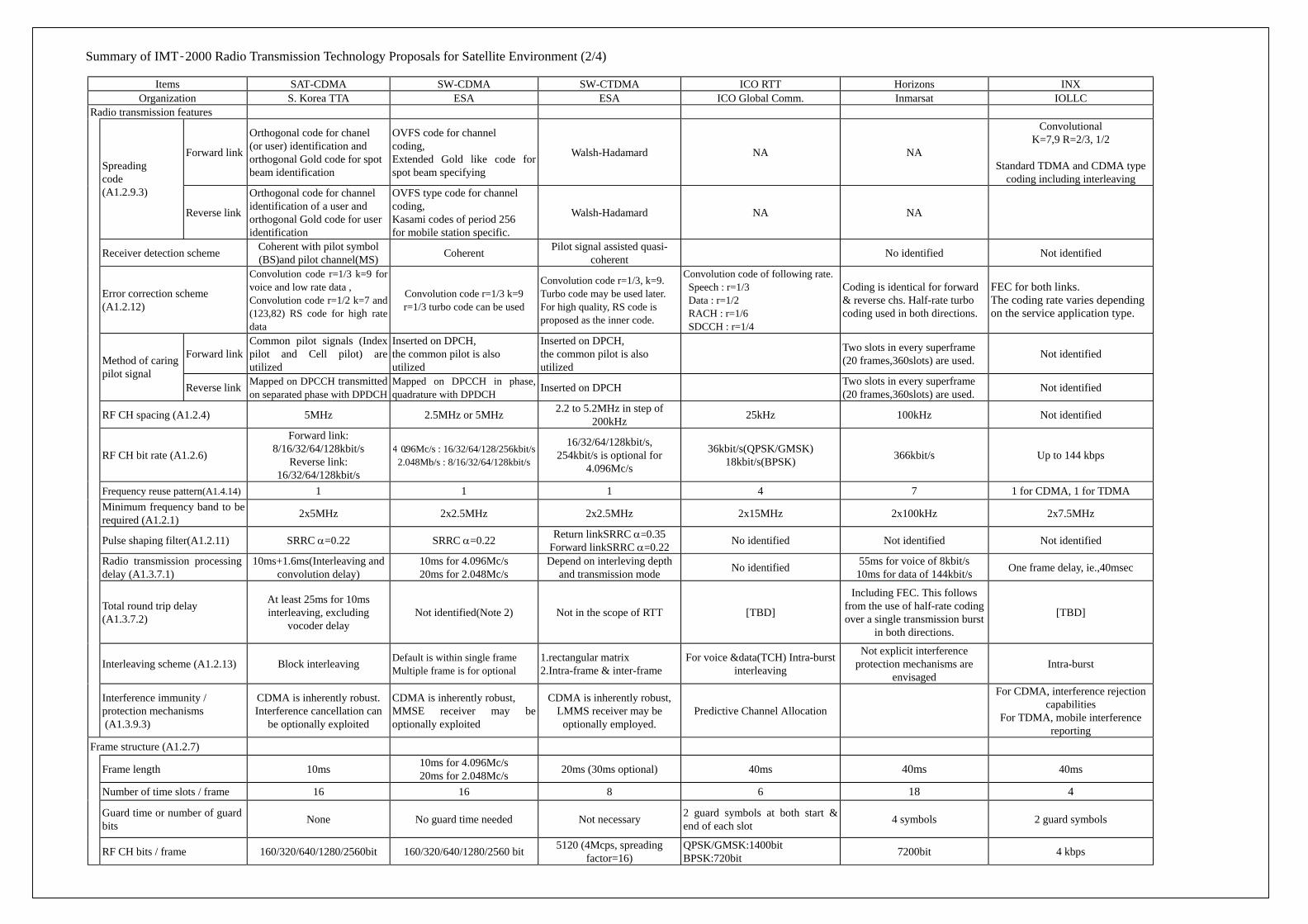
Summary of IMT-2000 Radio Transmission Technology Proposals for Satellite Environment (2/4)
Items SAT-CDMA SW-CDMA SW-CTDMA ICO RTT Horizons INX Organization S. Korea TTA ESA ESA ICO Global Comm. Inmarsat IOLLC
Radio transmission features
Forward link
Orthogonal code for chanel (or user) identification and orthogonal Gold code for spot beam identification
OVFS code for channel coding, Extended Gold like code for spot beam specifying
Walsh-Hadamard NA NA
Convolutional K=7,9 R=2/3, 1/2
Standard TDMA and CDMA type
coding including interleaving
Spreading code (A1.2.9.3)
Reverse link
Orthogonal code for channel identification of a user and orthogonal Gold code for user identification
OVFS type code for channel coding, Kasami codes of period 256 for mobile station specific.
Walsh-Hadamard NA NA
Receiver detection scheme Coherent with pilot symbol (BS)and pilot channel(MS) Coherent Pilot signal assisted quasi-
coherent No identified Not identified
Error correction scheme (A1.2.12)
Convolution code r=1/3 k=9 for voice and low rate data , Convolution code r=1/2 k=7 and (123,82) RS code for high rate data
Convolution code r=1/3 k=9 r=1/3 turbo code can be used
Convolution code r=1/3, k=9. Turbo code may be used later. For high quality, RS code is proposed as the inner code.
Convolution code of following rate. Speech : r=1/3 Data : r=1/2 RACH : r=1/6 SDCCH : r=1/4
Coding is identical for forward & reverse chs. Half-rate turbo coding used in both directions.
FEC for both links. The coding rate varies depending on the service application type.
Forward link Common pilot signals (Index pilot and Cell pilot) are utilized
Inserted on DPCH, the common pilot is also utilized
Inserted on DPCH, the common pilot is also utilized
Two slots in every superframe (20 frames,360slots) are used. Not identified
Method of caring pilot signal
Reverse link Mapped on DPCCH transmitted on separated phase with DPDCH
Mapped on DPCCH in phase, quadrature with DPDCH Inserted on DPCH Two slots in every superframe
(20 frames,360slots) are used. Not identified
RF CH spacing (A1.2.4) 5MHz 2.5MHz or 5MHz 2.2 to 5.2MHz in step of 200kHz 25kHz 100kHz Not identified
RF CH bit rate (A1.2.6)
Forward link: 8/16/32/64/128kbit/s
Reverse link: 16/32/64/128kbit/s
4. 096Mc/s : 16/32/64/128/256kbit/s 2.048Mb/s : 8/16/32/64/128kbit/s
16/32/64/128kbit/s, 254kbit/s is optional for
4.096Mc/s
36kbit/s(QPSK/GMSK) 18kbit/s(BPSK) 366kbit/s Up to 144 kbps
Frequency reuse pattern(A1.4.14) 1 1 1 4 7 1 for CDMA, 1 for TDMA Minimum frequency band to be required (A1.2.1) 2x5MHz 2x2.5MHz 2x2.5MHz 2x15MHz 2x100kHz 2x7.5MHz
Pulse shaping filter(A1.2.11) SRRC α=0.22 SRRC α=0.22 Return linkSRRC α=0.35 Forward linkSRRC α=0.22 No identified Not identified Not identified
Radio transmission processing delay (A1.3.7.1)
10ms+1.6ms(Interleaving and convolution delay)
10ms for 4.096Mc/s 20ms for 2.048Mc/s
Depend on interleving depth and transmission mode No identified 55ms for voice of 8kbit/s
10ms for data of 144kbit/s One frame delay, ie.,40msec
Total round trip delay (A1.3.7.2)
At least 25ms for 10ms interleaving, excluding
vocoder delay Not identified(Note 2) Not in the scope of RTT [TBD]
Including FEC. This follows from the use of half-rate coding over a single transmission burst
in both directions.
[TBD]
Interleaving scheme (A1.2.13) Block interleaving Default is within single frame Multiple frame is for optional
1.rectangular matrix 2.Intra-frame & inter-frame
For voice &data(TCH) Intra-burst interleaving
Not explicit interference protection mechanisms are
envisaged Intra-burst
Interference immunity / protection mechanisms (A1.3.9.3)
CDMA is inherently robust. Interference cancellation can
be optionally exploited
CDMA is inherently robust, MMSE receiver may be optionally exploited
CDMA is inherently robust, LMMS receiver may be
optionally employed. Predictive Channel Allocation
For CDMA, interference rejection capabilities
For TDMA, mobile interference reporting
Frame structure (A1.2.7)
Frame length 10ms 10ms for 4.096Mc/s 20ms for 2.048Mc/s 20ms (30ms optional) 40ms 40ms 40ms
Number of time slots / frame 16 16 8 6 18 4
Guard time or number of guard bits None No guard time needed Not necessary 2 guard symbols at both start &
end of each slot 4 symbols 2 guard symbols
RF CH bits / frame 160/320/640/1280/2560bit 160/320/640/1280/2560 bit 5120 (4Mcps, spreading factor=16)
QPSK/GMSK:1400bit BPSK:720bit 7200bit 4 kbps
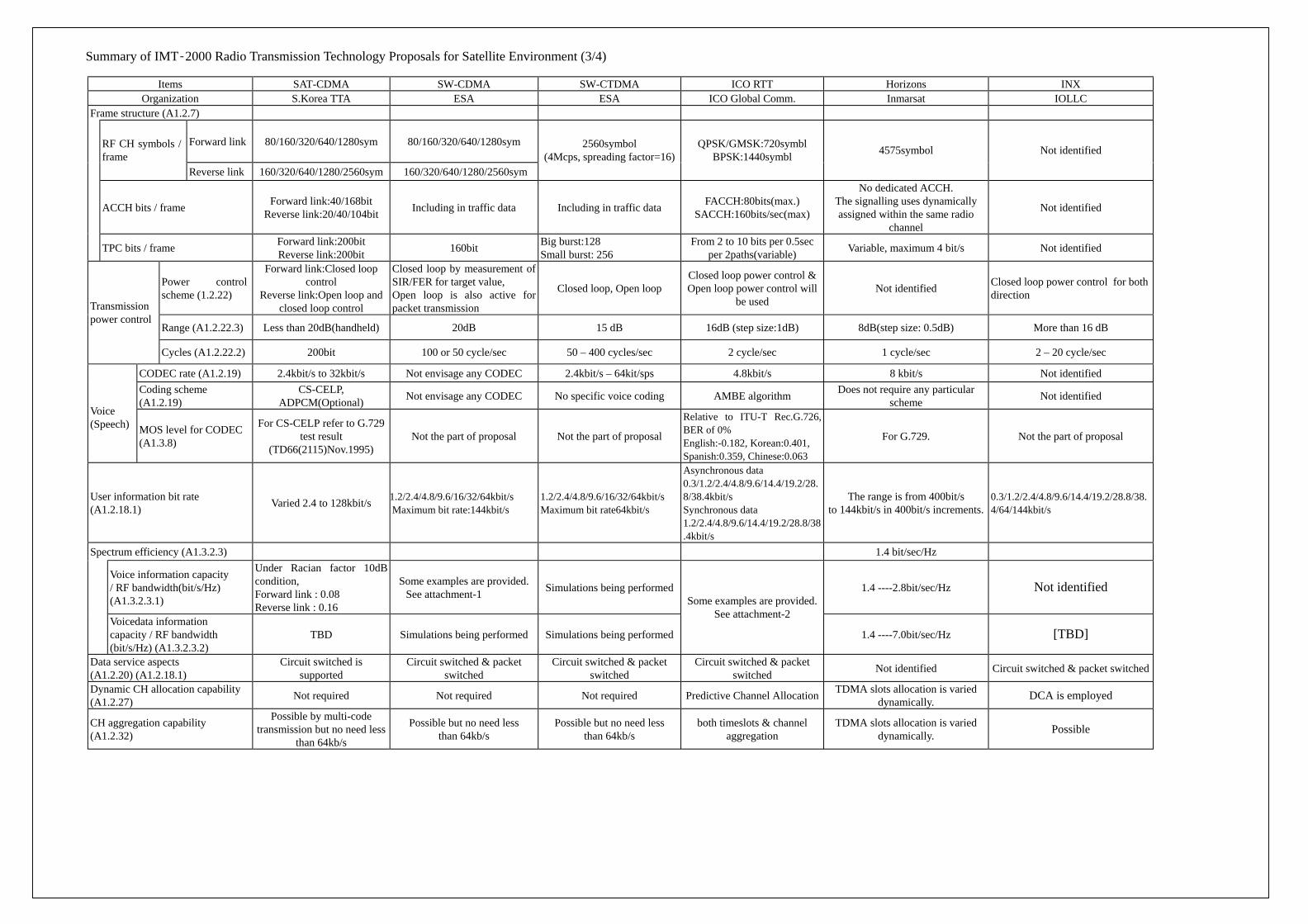
Summary of IMT-2000 Radio Transmission Technology Proposals for Satellite Environment (3/4)
Items SAT-CDMA SW-CDMA SW-CTDMA ICO RTT Horizons INX Organization S.Korea TTA ESA ESA ICO Global Comm. Inmarsat IOLLC
Frame structure (A1.2.7)
Forward link 80/160/320/640/1280sym 80/160/320/640/1280sym RF CH symbols / frame
Reverse link 160/320/640/1280/2560sym 160/320/640/1280/2560sym
2560symbol (4Mcps, spreading factor=16)
QPSK/GMSK:720symbl BPSK:1440symbl 4575symbol Not identified
ACCH bits / frame Forward link:40/168bit Reverse link:20/40/104bit Including in traffic data Including in traffic data FACCH:80bits(max.)
SACCH:160bits/sec(max)
No dedicated ACCH. The signalling uses dynamically assigned within the same radio
channel
Not identified
TPC bits / frame Forward link:200bit Reverse link:200bit 160bit Big burst:128
Small burst: 256 From 2 to 10 bits per 0.5sec
per 2paths(variable) Variable, maximum 4 bit/s Not identified
Power control scheme (1.2.22)
Forward link:Closed loop control
Reverse link:Open loop and closed loop control
Closed loop by measurement of SIR/FER for target value, Open loop is also active for packet transmission
Closed loop, Open loop Closed loop power control & Open loop power control will
be used Not identified Closed loop power control for both
direction
Range (A1.2.22.3) Less than 20dB(handheld) 20dB 15 dB 16dB (step size:1dB) 8dB(step size: 0.5dB) More than 16 dB
Transmission power control
Cycles (A1.2.22.2) 200bit 100 or 50 cycle/sec 50 – 400 cycles/sec 2 cycle/sec 1 cycle/sec 2 – 20 cycle/sec
CODEC rate (A1.2.19) 2.4kbit/s to 32kbit/s Not envisage any CODEC 2.4kbit/s – 64kit/sps 4.8kbit/s 8 kbit/s Not identified Coding scheme (A1.2.19)
CS-CELP, ADPCM(Optional) Not envisage any CODEC No specific voice coding AMBE algorithm Does not require any particular
scheme Not identified Voice (Speech) MOS level for CODEC
(A1.3.8)
For CS-CELP refer to G.729 test result
(TD66(2115)Nov.1995) Not the part of proposal Not the part of proposal
Relative to ITU-T Rec.G.726, BER of 0% English:-0.182, Korean:0.401, Spanish:0.359, Chinese:0.063
For G.729. Not the part of proposal
User information bit rate (A1.2.18.1) Varied 2.4 to 128kbit/s 1.2/2.4/4.8/9.6/16/32/64kbit/s
Maximum bit rate:144kbit/s 1.2/2.4/4.8/9.6/16/32/64kbit/s Maximum bit rate64kbit/s
Asynchronous data 0.3/1.2/2.4/4.8/9.6/14.4/19.2/28.8/38.4kbit/s Synchronous data 1.2/2.4/4.8/9.6/14.4/19.2/28.8/38.4kbit/s
The range is from 400bit/s to 144kbit/s in 400bit/s increments.
0.3/1.2/2.4/4.8/9.6/14.4/19.2/28.8/38.4/64/144kbit/s
Spectrum efficiency (A1.3.2.3) 1.4 bit/sec/Hz
Voice information capacity / RF bandwidth(bit/s/Hz) (A1.3.2.3.1)
Under Racian factor 10dB condition, Forward link : 0.08 Reverse link : 0.16
Some examples are provided. See attachment-1 Simulations being performed 1.4 ----2.8bit/sec/Hz Not identified
Voicedata information capacity / RF bandwidth (bit/s/Hz) (A1.3.2.3.2)
TBD Simulations being performed Simulations being performed
Some examples are provided. See attachment-2
1.4 ----7.0bit/sec/Hz [TBD]
Data service aspects (A1.2.20) (A1.2.18.1)
Circuit switched is supported
Circuit switched & packet switched
Circuit switched & packet switched
Circuit switched & packet switched Not identified Circuit switched & packet switched
Dynamic CH allocation capability (A1.2.27) Not required Not required Not required Predictive Channel Allocation TDMA slots allocation is varied
dynamically. DCA is employed
CH aggregation capability (A1.2.32)
Possible by multi-code transmission but no need less
than 64kb/s
Possible but no need less than 64kb/s
Possible but no need less than 64kb/s
both timeslots & channel aggregation
TDMA slots allocation is varied dynamically. Possible
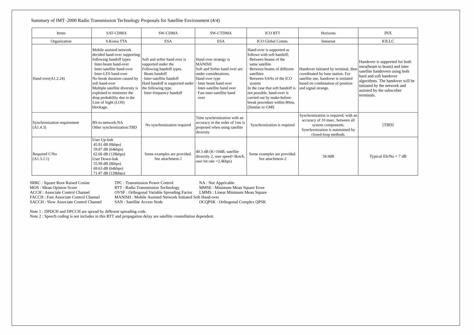
Summary of IMT-2000 Radio Transmission Technology Proposals for Satellite Environment (4/4)
Items SAT-CDMA SW-CDMA SW-CTDMA ICO RTT Horizons INX
Organization S.Korea TTA ESA ESA ICO Global Comm. Inmarsat IOLLC
Hand over(A1.2.24)
Mobile assisted network decided hand-over supporting following handoff types · Inter-beam hand-over · Inter-satellite hand-over · Inter-LES hand-over No break duration caused by soft hand-over Multiple satellite diversity is exploited to minimize the drop probability due to the Line of Sight (LOS) blockage.
Soft and softer hand over is supported under the Following handoff types. · Beam handoff · Inter-satellite handoff Hard handoff is supported under the following type. · Inter-frequency handoff
Hand over strategy is MANISH Soft and Softer hand over are under considerations. Hand over type · Inter beam hand over · Inter-satellite hand over · Fast inter-satellite hand over
Hand-over is supported as follows with soft handoff; · Between beams of the same satellite · Between beams of different satellites · Between SANs of the ICO system In the case that soft handoff is not possible, hand-over is carried out by make-before- break procedure within 80ms. (Similar to GMS
Handover initiated by terminal, then coordinated by base station. For satellite use, handover is initiated based on combination of position and signal strange.
Handover is supported for both intra(beam to beam) and inter satellite handovern using both hard and soft handover algorithms. The handover will be initiated by the network and assisted by the subscriber terminals.
Synchronization requirement (A1.4.3)
BS-to-network:NA Other synchronization:TBD No synchronization required
Time synchronization with an accuracy in the order of 1ms is proposed when using satellite diversity
Synchronization is required
Synchronization is required, with an accuracy of 10 msec, between all
system components. Synchronization is maintained by
closed-loop methods.
[TBD]
Required C/No (A1.3.2.1)
User Up-link 45.81 dB (8kbps) 59.87 dB (64kbps) 62.66 dB (128kbps) User Down-link 55.99 dB (8kbps) 69.63 dB (64kbps) 71.87 dB (128kbps)
Some examples are provided. See attachment-1
40.3 dB (K=10dB, satellite diversity 2, user speed=3km/h, user bit rate =2.4kbps)
Some examples are provided. See attachment-2 58.9dB Typical Eb/No = 7 dB
SRRC : Square Root Raised Cosine TPC : Transmission Power Control NA : Not Appricable MOS : Mean Opinion Score RTT : Radio Transmission Technology MMSE : Minimum Mean Square Error ACCH : Associate Control Channel OVSF : Orthogonal Variable Spreading Factor LMMS : Linear Minimum Mean Square FACCH : Fast Associate Control Channel MANISH : Mobile Assisted Network Initiated Soft Hand-over SACCH : Slow Associate Control Channel SAN : Satellite Access Node OCQPSK : Orthogonal Complex QPSK Note 1 : DPDCH and DPCCH are spread by different spreading code. Note 2 : Speech coding is not includes in this RTT and propagation delay are satellite constellation dependent.
ARIB TR-T15
34
ANNEX 6 Terminologies and Abbreviations 1 Scope This Annex is a collection of terms and abbreviations related to the Technical Report regarding IMT-2000 MSS. This Annex provides the information for their understanding. The terms, definitions and abbreviations as given in this Annex are either imported from existing document (ITU, ARIB or elsewhere) or newly created by satellite working group experts at ARIB. 2 Reference This existing document contains ITU recommendations, 3GPP and 3GPP2 documents as references. 3 Terms and definitions related to the Radio Interface of IMT-2000 MSS
C
Compatibility; A degree of transparency sufficient to support an acceptable grade of service with respect to a connection between system entities. Full compatibility implies full transparency. Code excited linear prediction (CELP); A type of speech coding system where voice wave forms are analysed into parameters before they are transmitted.
E Emergency service; A telecommunication service, which is used to access a public emergency centre, characterized by a locally significant access number, high priority, and distinctive feature interactions. Encryption; A function used to transform data so as to hide its information content to prevent it's unauthorized use.
F
Feeder link (satellite); A radio transmission link between land earth station and space station. Fixed public network; PSTN, PDN, ISDN and so on. Fixed station; An equipment which terminates radio interface and is fixed. FPLMTS; Those systems that conform to the corresponding series of ITU Recommendations and Radio Regulations(now IMT-2000). Referred from ITU-R M.1224. Geostationary orbit (GSO); The orbit of a geosynchronous satellite whose circular and direct orbit lies in the plane of the Earth's equator.
H Handover; The action of switching a call in progress from one cell to another (intercell) or between radio channels in the same cell (intracell) without interruption of the call.
ARIB TR-T15
35
NOTE 1 - Handover is used to allow established calls to continue when mobile stations move from one cell to another (or as a method to minimize co-channel interference). Referred from ITU-R M.1224.
Highly inclined elliptical orbit (HEO); An elliptical orbit most typically with a perigee of 500 km or more and a apogee of 50 000 km or less altitude above the Earth's surface with an inclination angle greater than 40° from the equatorial plane. Referred from ITU-R M.1224.
I IMT-2000; Those systems that conform to the corresponding series of ITU Recommendations and Radio Regulations(formerly FPLMTS). Referred from ITU-R M.1224. Intelligent network (IN); A telecommunication network based on an architecture that provides flexibility for facilitating the introduction of new capabilities and services, including those under customer control. Referred from ITU-R M.1224. Interworking; The means of supporting communications and interactions between entities in different networks or systems. Referred from ITU-R M.1224. Interoperability; The ability of multiple entities in different networks or systems to operate together without the need for additional conversion or mapping of states and protocols. Referred from ITU-R M.1224. Interworking functions; Mechanisms which mask the differences in physical, link, and network technologies by converting or mapping states and protocols into consistent network and user services. Referred from ITU-R M.1224.
L Location service; A particular mobility service in which location information can be provided to authorized users or to relevant authorities in case of emergency calls or for vehicular traffic management. Referred from ITU-R M.1224. Low-Earth orbit (LEO); A circular or elliptical orbit of about 700 to 3 000 km altitude above the Earth's surface. Referred from ITU-R M.1224.
M Macro cells; Cells with a large cell radius, typically several tens of km. (Radius of 35 km.). Referred from ITU-R M.1224.
NOTE 1 - The radius of a cell can be extended by the use of directional antennas. NOTE 2 - Macro cells are characterized by low-to-medium traffic density, support for moderate mobile station speeds and narrow band services. NOTE 3 - A typical macro cell may be situated in a rural or suburban environment, with moderate building blockage, and, depending on terrain, significant foliage blockage.
Medium-Earth orbit (MEO); A circular or elliptical orbit of about 8 000 to 20 000 km altitude above the Earth's surface. Referred from ITU-R M.1224. Mobile earth station (MES); An entity capable of accessing a set of 3G Mobile System satellite services.
ARIB TR-T15
36
This entity may be stationary or in motion within the 3G Mobile System service area while accessing 3G Mobile System satellite services and may simultaneously serve one or more user. Referred from ITU-R M.1224.
NOTE 1 - A user of a mobile earth station may also have several simultaneous connections with the network.
Micro cells; Cells with low antenna sites, predominantly in urban areas, with a typical cell radius of up to 1 km. Referred from ITU-R M.1224.
NOTE 1 - Micro cells are characterized by medium-to-high traffic density, low mobile station speeds and narrow-band services. NOTE 2 - Blockage by man-made structures may be significant in a micro cell environment.
Mobile station (MS); A station in the mobile service intended to be used while in motion or during halts at unspecified points. Referred from ITU-R M.1224. Mobile termination (MT); The part of the mobile station which terminates the radio path at the mobile side and adapts the capabilities of the radio path to the capabilities of the terminal equipment. Referred from ITU-R M.1224.
P Power control; Dynamic adjustment of the output power to minimize the total interference in the system, while maintaining sufficient quality of any connection.
Q Quality of service (QoS); The collective effect of service performances which determine the degree of satisfaction of a user of a service. It is characterized by the combined aspects of performance factors applicable to all services, such as:
- service operability performance, - service accessibility performance, - service retainability performance, - service integrity performance, - other factors specific to each service.
R
Radio-frequency(RF) channel; A specified portion of the RF spectrum with a defined bandwidth and a carrier frequency and is capable of carrying information over the radio interface. Radio interface; The common boundary between the mobile station and the radio equipment in the network, defined by functional characteristics, common radio (physical) interconnection characteristics, and other characteristics, as appropriate.
NOTE 1 - An interface standard specifies the bi-directional interconnection between both sides of the interface at once. The specification includes the type, quantity and function of the interconnecting means and the type, form and sequencing order of the signals to be interchanged by those means. The term "air interface" is synonymous with the term "radio interface". See also "3G Mobile System radio interface".
Radio interface protocol; The protocol used across the radio interface (usually a collection of protocols
ARIB TR-T15
37
supporting various layers of the protocol reference model). Reverse link; A unidirectional radio pathway for the transmission of signals from one or more mobile stations to one base station. Same as uplink (terrestrial) in M.1224. Roaming; The a user to access wireless telecommunication services in areas bility of a other than the ones where the user is subscribed
S Security; The protection of information availability, integrity and confidentiality. Service; A set of functions offered to a user by an organization. Service access point; An access point at which the layer (N – 1) provides the (N – 1) services to (N) entities. Service area; The area within which a mobile station can access the 3G Mobile System services. A service area may consist of several 3G Mobile System networks. One service area may consist of one country, be a part of a country or comprise of several countries. Service availability; An availability to a set of service capabilities offered to a user by an organization/3G Mobile System service provider. Service feature; Network function associated with a particular basic or supplementary service in order to upgrade such services in the interest of higher comfort to the users but, in general, not offered to them as a service on its own. Service link; A bi-directional radio transmission link between space station and MES/PES/SP. Service provider; A person or an other entity that has the overall responsibility for the provision of a service or a set of services to the users and for negotiating network capabilities associated with the services he/she provides. Short message; An information block transferred as a whole by means of the Short Message Service. Subscriber; A person or other entity that has a contractual relationship with a service provider on behalf of one or more users. (A subscriber is responsible for the payment of charges due to that service provider.)
NOTE 1 - Sometimes the term "3G Mobile System subscriber" is used interchangeably with "subscriber", especially where it is necessary to distinguish a person or organization which subscribes directly to a 3G Mobile System service from one which benefits from 3G Mobile System services.
Supplementary service; A service which modifies or supplements a basic telecommunication service. Consequently, it can not be offered to a customer as a standalone service, rather, it must be offered together with or in association with a basic telecommunication service. The same supplementary service may be common to a number of telecommunication services. System; A regularly interacting or interdependent group of items forming a unified whole technology.
T Telephone service; A public telecommunication service primarily intended for the exchange of information
ARIB TR-T15
38
in the form of speech, whereby users can communicate directly and temporarily between themselves in conversational mode, and should be provided in accordance with the International Telecommunication Regulations, and the relevant ITU-T Recommendations.
NOTE 1 - The international telephone service can also support a number of non-voice services such as facsimile and data transmission.
Teleservice; A type of telecommunication service that provides the complete capability, including terminal equipment functions, for communication between users according to protocols established by agreement between administrations and/or ROAs Terminal; The equipment which interfaces the end user with 3G Mobile System. Terminal mobility; The ability of a terminal to access telecommunications services from different locations and while in motion, and the capability of the network to identify and locate that terminal or the associated subscriber.
NOTE 1 - This ability implies the availability of telecommunication services, ideally, in all areas and at all times. Terminal mobility may be provided according to the mobile terminal's service profile.
Traffic capacity; The total traffic that can be supported by a single cell (or spot beam), which is part of an infinite set of identical cells (or large number of satellite spot beams) in a uniform two-dimensional (or three-dimensional) pattern.
NOTE 1 - The traffic capacity must be specified at a stated spectrum allocation, quality and grade of service, assuming an appropriate propagation model. This metric, is measured in Erlang/cell or Erlang/satellite spot beam, and is valuable for comparing systems with identical user channel requirements.
Traffic channel; A point-to-point bidirectional channel which transfers user information and the user information control signal. The TCH transfers voice and facsimile information. Transmission performance; The reproducibility of a signal input to a telecommunications network under given conditions. The given conditions may include the effect of propagation performance where applicable.
ARIB TR-T15
39
4. Abbreviation For the purposes of the present document, the following abbreviations apply: Abbreviation Term 2G Second Generation system 3G Third Generation system 3GPP Third Generation Partnership Project 3GPP2 Third Generation Partnership Project 2 AEC Acoustic Echo Controllers AM Amplitude Modulation ANSI American National Standards Institute ARIB Association of radio Industries and Businesses (formerly RCR) ARQ Automatic Repeat Request ASIC Application Spec Integrated Circuits BER Bit Error Rate BPSK Binary Phase Shift Keying (Modulation) BS Base Station C/I Carrier to Interference (Power) Ratio C/N Carrier to Noise (Power) Ratio CCIR International Radio Consultative Committee, later ITU-R CCITT International Telegraph and Telephone Consultative Committee CDF Cumulative Distribution Function CDMA Code Division Multiple Access CN Core Network CODEC Coder and/or Decoder CPM Conference Preparatory Meeting CRC Cyclic Redundancy Check CS Cell Station CWTS China Wireless Telecommunications Standards Group DL Downlink (Service Link) DPCH Dedicated Physical Channel DPCCH Dedicated Physical Control Channel DPDCH Dedicated Physical Data Channel DCCH Dedicated Control Channel DCH Dedicated Channel DTCH Dedicated Traffic Channel DS-CDMA Direct Spreading CDMA DSP Digital Signal Processor DTMF Dual Tone Multiple Frequency Eb/No Power per Bit to Noise Density Ratio EEC Electronic Equipment Cabinet EMC Electromagnetic Compatibility ETSI European Telecommunications Standards Institute FAX Facsimile FDD Frequency Division Duplex FEC Forward Error Correction
ARIB TR-T15
40
FFS For Further Study FM Frequency Modulation FPLMTS Future Public Land Mobile Telecommunication Systems FTP File Transfer Protocol FWA Fixed Wireless Access GOS Grade of Service GSM Global System for Mobile Communication (Phone) GSO Geostationary Satellite Orbit (Satellite) HAPS High Altitude Platform Station HEO Highly Inclined Elliptical Orbit (Satellite) ID Identification IMT-2000 International Mobile Telecommunication 2000 (System Concept) IP Internet Protocol ISC International Switching Center ISDN Integrated Services Digital Network ISL Inter Satellite Link ITU International Telecommunication Union ITU-R International Telecommunication Union - Radio Communication Sector ITU-T International Telecommunication Union - Telecommunication Standardization
Sector Iu IMT-2000 Radio Interface IWF Inter-working Function LEO Low Earth Orbit (Satellite) LES Land Earth Station LMSS Land Mobile Satellite System LOS Line of Sight (Path) LX Local Exchange MC-CDMA Multi Carrier CDMA ME Mobile Station MEO Medium Earth Orbit (Satellite) MES Mobile Earth Station MODEM Modulator and/or Demodulator MOS Mean Opinion Score MSC Mobile Services Switching Center MSS Mobile Satellite Service MT Mobile Termination NLOS Non Line of Sight (Path) OSI Open Systems Interconnection PDC Personal Digital Cellular pdf Probability Density Function PDN Public Data Network PES Personal Earth Station PFD Power Flux Density PLL Phase Lock Loop PLMN Public Land Mobile Network PN Persuade Noise (Code) POW Poor or Worst
ARIB TR-T15
41
PS Personal Station PSTN Public Switched telephone Network QoS Quality of Service QPSK Quadrate Phase Shift Keying (Modulation) RAN Radio Access Network RANI Radio Access Network Interface RF Radio Frequency RR Radio Regulation RTT Radio Transmission Technology SF Spreading Factor SFD Saturation Flux Density SRAN Satellite RAN TAF Terminal Adaptation Function TCP Transmission Control Protocol TDD Time Division Duplex TE Terminal Equipment TG Task Group TIA The Telecommunications Industry Association TPC Transmission Power Control TTA The Telecommunications Technology Association TTC The Telecommunications Technology Council UDP User Datagram Protocol UIM User Identify Module UL Uplink (Forward Link) VA Voice Activity (Ratio) WARC The World Administrative Radio Conference, later WRC W-CDMA Wideband CDMA WG Working Group WILL Wireless Local Loop WRC World Radio Communication Conference WWW World Wide Web
TECHNICAL REPORT OF MOBILE SATELLITE SYSTEM CONSIDERATION FOR 3G MOBILE SYSTEM
ARIB Technical Report
ARIB TR-T15 VERSION 1.00
Issued June 2000 The first print
Published by
Association of Radio Industries and Businesses (ARIB)
Nittochi Bldg. 14F 1-4-1 Kasumigaseki, Chiyoda-ku, Tokyo 100-0013, Japan
TEL +81-3-5510-8590 FAX +81-3-3592-1103
Printed in Japan All rights reserved