Embed Size (px)
Citation preview
3GPP TR 23.856 V10.0.0 (2010-09)Technical Report
3rd Generation Partnership Project;Technical Specification Group Services and System Aspects;
Single Radio Voice Call Continuity (SRVCC) enhancements;Stage 2
(Release 10)
The present document has been developed within the 3rd Generation Partnership Project (3GPP TM) and may be further elaborated for the purposes of 3GPP.The present document has not been subject to any approval process by the 3GPP Organizational Partners and shall not be implemented.This Specification is provided for future development work within 3GPP only. The Organizational Partners accept no liability for any use of this Specification.Specifications and reports for implementation of the 3GPP TM system should be obtained via the 3GPP Organizational Partners' Publications Offices.

3GPP
3GPP TR 23.856 V10.0.0 (2010-09)2Release 10
Keywords IMS, SRVCC, Handover performance
3GPP
Postal address
3GPP support office address 650 Route des Lucioles - Sophia Antipolis
Valbonne - FRANCE Tel.: +33 4 92 94 42 00 Fax: +33 4 93 65 47 16
Internet http://www.3gpp.org
Copyright Notification
No part may be reproduced except as authorized by written permission. The copyright and the foregoing restriction extend to reproduction in all media.
© 2010, 3GPP Organizational Partners (ARIB, ATIS, CCSA, ETSI, TTA, TTC).
All rights reserved.
UMTS™ is a Trade Mark of ETSI registered for the benefit of its members 3GPP™ is a Trade Mark of ETSI registered for the benefit of its Members and of the 3GPP Organizational Partners LTE™ is a Trade Mark of ETSI currently being registered for the benefit of its Members and of the 3GPP Organizational Partners GSM® and the GSM logo are registered and owned by the GSM Association
3GPP
3GPP TR 23.856 V10.0.0 (2010-09)3Release 10
Contents Foreword............................................................................................................................................................. 6 1 Scope ........................................................................................................................................................ 7 2 References ................................................................................................................................................ 7 3 Definitions and abbreviations ................................................................................................................... 8 3.1 Definitions ......................................................................................................................................................... 8 3.2 Abbreviations ..................................................................................................................................................... 8 4 Requirements ............................................................................................................................................ 8 4.1 General ............................................................................................................................................................... 8 4.2 Architectural Requirements ............................................................................................................................... 8 4.3 SRVCC Performance Requirements .................................................................................................................. 8 5 Performance Analysis of Rel-8 SRVCC solution .................................................................................... 9 5.1 Analysis of SRVCC handover performance from EUTRAN to UTRAN/GERAN ........................................... 9 5.2 Analysis of SRVCC handover performance from HSPA to UTRAN/GERAN ............................................... 10 5.3 Analysis of call drop probability in SRVCC ................................................................................................... 10 6 Alternatives ............................................................................................................................................ 11 6.1 Alternative 1 - enhancement using delay prediction ........................................................................................ 11 6.1.1 Sub-alternative #1 – prediction in MSC server .......................................................................................... 11 6.1.1.1 Architecture Reference Model .............................................................................................................. 11 6.1.1.2 Functional Entities ................................................................................................................................ 11 6.1.1.2.1 MSC Server ..................................................................................................................................... 11 6.1.1.3 Message Flows ..................................................................................................................................... 11 6.1.1.4 A way using Pre-handover optimization to reduce the call drop probability........................................ 13 6.1.2 Sub-alternative #2 - prediction in SCC AS ................................................................................................ 13 6.1.2.1 Architecture Reference Model .............................................................................................................. 13 6.1.2.2 Functional Entities ................................................................................................................................ 13 6.1.2.2.1 SCC AS ........................................................................................................................................... 13 6.1.2.2.2 MSC Server ..................................................................................................................................... 14 6.1.2.3 Message Flows ..................................................................................................................................... 14 6.2 Alternative 2 - Serial Handover ....................................................................................................................... 16 6.2.1 Architecture Reference Model ................................................................................................................... 16 6.2.2 Functional Entities ..................................................................................................................................... 16 6.2.3 Message Flows ........................................................................................................................................... 16 6.3 Void ................................................................................................................................................................. 17 6.4 Alternative 4 - Media anchor in the serving network....................................................................................... 17 6.4.1 Architecture Reference Model ................................................................................................................... 17 6.4.2 Functional Entities ..................................................................................................................................... 18 6.4.3 Message Flows ........................................................................................................................................... 18 6.4.3.1a Originating sessions in PS .................................................................................................................... 18 6.4.3.1b Termination sessions in PS ................................................................................................................... 19 6.4.3.2 PS – CS Access Transfer ...................................................................................................................... 19 6.4.4 Deployment Alternatives ............................................................................................................................ 20 6.4.5 Selection of VATF ..................................................................................................................................... 21 6.4.6 Maintaining IMS registration ..................................................................................................................... 21 6.5 Alternative 5 - Remote update optimization .................................................................................................... 22 6.5.1 Architecture Reference Model ................................................................................................................... 22 6.5.2 Functional Entities ..................................................................................................................................... 22 6.5.3 Message Flows ........................................................................................................................................... 22 6.6 Void ................................................................................................................................................................. 23 6.7 Void ................................................................................................................................................................. 23 6.8 Alternative 8 – SR-VCC Enhancement using anchoring in the home network ............................................... 23 6.8.1 Sub-alternative #1: MRF selective media anchoring controlled directly by the SCC AS .......................... 23 6.8.1.1 Architecture Reference Model ............................................................................................................. 24 6.8.1.2 Functional Entities ................................................................................................................................ 24

3GPP
3GPP TR 23.856 V10.0.0 (2010-09)4Release 10
6.8.1.3 Message flows ...................................................................................................................................... 24 6.8.1.3.1 Call origination ............................................................................................................................... 25 6.8.1.3.2 Call termination .............................................................................................................................. 26 6.8.1.3.3 SRVCC procedure .......................................................................................................................... 26 6.8.2 Sub-alternative #2: Selective media anchoring controlled by a node other than the SCC AS ................... 28 6.8.2.1 Architecture Reference Model .............................................................................................................. 28 6.8.2.2 Functional Entities ................................................................................................................................ 28 6.8.2.3 Message flows ...................................................................................................................................... 28 6.8.2.3.1 Call origination ............................................................................................................................... 29 6.8.2.3.2 Call termination .............................................................................................................................. 30 6.8.2.3.3 SRVCC procedure .......................................................................................................................... 32 6.9 Alternative 9 – SR-VCC Enhancement using media detection ........................................................................ 34 6.9.1 Introduction ................................................................................................................................................ 34 6.9.2 Call flows ................................................................................................................................................... 36 6.10 Alternatives 10 - eSRVCC with PDN bi-casting ............................................................................................. 37 6.10.1 Architecture Reference Model ................................................................................................................... 37 6.10.2 Functional Requirements ............................................................................................................................ 38 6.10.2a IMS voice codec retrieval from PCC flow ................................................................................................. 38 6.10.3 Media plane handling ................................................................................................................................. 39 6.10.4 Signalling Message Flows .......................................................................................................................... 40 6.11 Alternative 11 - Media anchoring in the IMS-ALG ......................................................................................... 41 6.11.0 General ....................................................................................................................................................... 41 6.11.1 Architecture Reference Model ................................................................................................................... 41 6.11.2 Functional Entities ..................................................................................................................................... 41 6.11.3 Message Flows ........................................................................................................................................... 41 6.11.3.1 IMS Registration .................................................................................................................................. 41 6.11.3.2 Originating sessions in PS .................................................................................................................... 42 6.11.3.3 Terminating sessions in PS ................................................................................................................... 43 6.11.3.4 PS – CS Access Transfer ...................................................................................................................... 44 6.12 Alternative 12 - HO enhancement by local anchoring with Indirect Forwarding (Merged alternative of
alternatives 6 and 7) ......................................................................................................................................... 44 6.12.1 Architecture Reference Model ................................................................................................................... 44 6.12.2 Functional Entities ..................................................................................................................................... 45 6.12.2.1 MSC Server/MGW enhanced for E-UTRAN/UTRAN (HSPA) and 3GPP UTRAN/GERAN
SRVCC ................................................................................................................................................. 45 6.12.2.2 PCC ...................................................................................................................................................... 46 6.12.2.3 MME .................................................................................................................................................... 46 6.12.2.4 S-GW .................................................................................................................................................... 46 6.12.3 Message Flows ........................................................................................................................................... 46 6.12.3.1 SRVCC Handover with PS HO support ............................................................................................... 46 6.12.3.2 SRVCC Handover without PS HO support .......................................................................................... 48 6.12.3.3 SRNS Relocation .................................................................................................................................. 50 6.12.3.4 SDP related information pre-fetching ................................................................................................... 52 6.12.3.5 SDP related information update............................................................................................................ 52 6.13 Consolidated Alternative – SIP based solution for eSRVCC .......................................................................... 53 6.13.1 Architecture Reference Model ................................................................................................................... 53 6.13.2 Functional Entities ..................................................................................................................................... 55 6.13.2.1 ATCF .................................................................................................................................................... 55 6.13.2.1.1 General ............................................................................................................................................ 55 6.13.2.1.2 ATCF anchoring ............................................................................................................................. 56 6.13.2.2 ATGW .................................................................................................................................................. 56 6.13.2.3 SCC AS ................................................................................................................................................ 57 6.13.2.4 HSS ....................................................................................................................................................... 57 6.13.3 Message Flows ........................................................................................................................................... 57 6.13.3.1 Selection of the ATCF .......................................................................................................................... 57 6.13.3.2 Originating sessions in PS .................................................................................................................... 59 6.13.3.3 Terminating sessions in PS ................................................................................................................... 60 6.13.3.4 PS-CS Access Transfer ......................................................................................................................... 61 6.13.3.4.1 PS-CS Access Transfer – ATGW anchored during session setup and supporting MSC Server
assisted mid-call feature .................................................................................................................. 61 6.13.3.4.2 PS-CS Access Transfer – ATGW anchored during session setup and MSC Server assisted
mid-call feature supported by SCC AS ........................................................................................... 63
3GPP
3GPP TR 23.856 V10.0.0 (2010-09)5Release 10
6.13.3.4.3 PS-CS Access Transfer – ATCF not included during registration .................................................. 64 6.13.3.4.4 PS-CS Access Transfer – ATGW not anchored during session setup ............................................ 64 6.13.3.5 Failure to complete PS-CS Access Transfer ......................................................................................... 66 7 Assessment ............................................................................................................................................. 66 7.1 Assessment Criteria ......................................................................................................................................... 66 7.2 Assessment of alternatives ............................................................................................................................... 67 8 Conclusion .............................................................................................................................................. 69
Annex A: Reducing the call drop probability ...................................................................................... 70 A.1 Pre-handover optimization ..................................................................................................................... 70 A.1.1 Architecture Reference Model ......................................................................................................................... 70 A.1.2 Functional Entities ........................................................................................................................................... 70 A.1.2.1 MSC Server ................................................................................................................................................ 70 A.1.2.2 MME .......................................................................................................................................................... 70 A.1.2.3 E-UTRAN .................................................................................................................................................. 70 A.1.2.4 UE .............................................................................................................................................................. 70 A.1.3 Message Flows ................................................................................................................................................. 70
Annex B: Impacts on nodes of eSRVCC alternatives ......................................................................... 73
Annex C: Examples of ATCF/ATGW collocation – SIP based solution for eSRVCC .................... 77 C.1 General ................................................................................................................................................... 77 C.2 IMS ALG/IMS AGW ............................................................................................................................. 77 C.3 IBCF/TrGW ........................................................................................................................................... 78
Annex D: Change history ...................................................................................................................... 80

3GPP
3GPP TR 23.856 V10.0.0 (2010-09)6Release 10
Foreword This Technical Specification has been produced by the 3rd Generation Partnership Project (3GPP).
The contents of the present document are subject to continuing work within the TSG and may change following formal TSG approval. Should the TSG modify the contents of the present document, it will be re-released by the TSG with an identifying change of release date and an increase in version number as follows:
Version x.y.z
where:
x the first digit:
1 presented to TSG for information;
2 presented to TSG for approval;
3 or greater indicates TSG approved document under change control.
y the second digit is incremented for all changes of substance, i.e. technical enhancements, corrections, updates, etc.
z the third digit is incremented when editorial only changes have been incorporated in the document.

3GPP
3GPP TR 23.856 V10.0.0 (2010-09)7Release 10
1 Scope SR-VCC has been standardized in Release 8 TS 23.216 [3] to provide seamless continuity when UE handovers from E-UTRAN to UTRAN/GERAN.
This document contains the results of feasibility study of the requirements and the alternative solutions to improve the handover performance of SRVCC.
The objective of this study is as follows:
- Evaluating the performance of current Rel-8 SRVCC solution;
- Enhancing the performance of the SR-VCC Flow Break with regard to the roaming and non-roaming case;
- Enhancing SR-VCC handover performance while minimizing the impacts on the network architecture for the directions
- from EUTRAN to UTRAN/GERAN; and
- from UTRAN to UTRAN/GERAN.
2 References The following documents contain provisions which, through reference in this text, constitute provisions of the present document.
· References are either specific (identified by date of publication, edition number, version number, etc.) or non-specific.
· For a specific reference, subsequent revisions do not apply.
· For a non-specific reference, the latest version applies. In the case of a reference to a 3GPP document (including a GSM document), a non-specific reference implicitly refers to the latest version of that document in the same Release as the present document.
[1] 3GPP TR 21.905: "Vocabulary for 3GPP Specifications".
[2] 3GPP TR 22.278: "Service requirements for the Evolved Packet System (EPS)".
[3] 3GPP TS 23.216: " Single Radio Voice Call Continuity (SRVCC); Stage 2".
[4] 3GPP TS 23.237: "IP Multimedia Subsystem (IMS) Service Continuity; Stage 2".
[5] 3GPP TS 36.133: "Requirements for support of radio resource management.
[6] 3GPP TS 23.401: "General Packet Radio Service (GPRS) enhancements for Evolved Universal Terrestrial Radio Access Network (E-UTRAN) access".
[7] 3GPP TS 23.292: "IP Multimedia Subsystem (IMS) centralized services".
[8] 3GPP TS 23.228: "IP Multimedia Subsystem (IMS); Stage 2".
[9] 3GPP TS 36.413: " Evolved Universal Terrestrial Radio Access (E-UTRA) ; S1 Application Protocol (S1AP)".
[10] 3GPP TS 23.272: "Circuit Switched Fallback in Evolved Packet System; Stage 2".
[11] IETF RFC 3264: "An Offer/Answer Model with the Session Description Protocol (SDP)".
[12] 3GPP TS 23.203: "Policy and charging control architecture".
3GPP
3GPP TR 23.856 V10.0.0 (2010-09)8Release 10
[13] 3GPP TS 23.334: "IP Multimedia Subsystem (IMS) Application Level Gateway (IMS-ALG) - IMS Access Gateway (IMS-AGW) interface: Procedures descriptions".
[14] 3GPP TS 23.206: "Voice Call Continuity (VCC) between Circuit Switched (CS) and IP Multimedia Subsystem (IMS); Stage 2".
3 Definitions and abbreviations
3.1 Definitions For the purposes of the present document, the terms and definitions given in TR 21.905 [1] apply.
3.2 Abbreviations For the purposes of the present document, the abbreviations given in TR 21.905 [1] apply.
4 Requirements
4.1 General - The impact to the existing SRVCC architecture should be minimized.
- NO impact on UE.
- The impact to the EPS should be minimized.
- The impact to the existing SRVCC procedure should be minimized.
4.2 Architectural Requirements Editor's Note: This clause will contain the requirements for the enhanced SRVCC architecture.
- The solution shall keep backward compatibility to the UE of previous releases.
- The solution shall support Local Breakout scenarios according to TS 23.228 [8], with the possibility of having the P-CSCF either in the visited network or in the home network.
- The SRVCC enhancement solution shall not negatively affect the SRVCC emergency call procedures.
4.3 SRVCC Performance Requirements Editor's Note: This clause will contain the requirements for the enhanced SRVCC handover performance.
- The interruption time of SRVCC is not higher than 300ms as required in TS 22.278 [2], from EUTRAN to UTRAN.

3GPP
3GPP TR 23.856 V10.0.0 (2010-09)9Release 10
5 Performance Analysis of Rel-8 SRVCC solution
5.1 Analysis of SRVCC handover performance from EUTRAN to UTRAN/GERAN
In TS 22.278 [2], the requirement for voice interruption time of a RAT change is defined, which should also apply to SRVCC:
- The RAT change procedure executed to enable service continuity for an established voice call shall target an interruption time not higher than 300 ms.
According to TS 23.216 [3], the IMS Session Transfer procedure is executed in parallel with the Handover from E-UTRAN to UTRAN/GERAN. Such as in clause 6.2.2.1, it is described as:
NOTE 3: Steps 11 (Session Transfer and Update remote end procedure) and 12 (Source IMS access leg release) are independent of step 13(Handover from E-UTRAN to GERAN procedure).
The procedure after Relocation Preparation procedure is shown in Figure 5.1.1. To make the analysis simpler and clearer, it is assumed that step a1 is preformed by MSC enhanced for SRVCC at the same time with step b1, or within a negligible short period.
Another assumption is that the transmission time for IMS bearers is short enough to be neglected in this analysis.
Downlink
Uplink
Downlink
Uplink
Figure 5.1.1: SRVCC Rel-8 from UTRAN (HSPA) to UTRAN/GERAN
The voice downlink media flow is interrupted after step a2 or step b2, and restored after both step a4 and step b3 are finished. So the interruption time of the downlink flow is:
- Td = MAX(Ta1+Ta2+Ta3+Ta4-Tb1-Tb2, Tb3)
The voice uplink media flow is interrupted after step b2, and restored after both step a4 and step b3 are finished. So the interruption time of the uplink flow is:
- Tu = MAX(Ta1+Ta2+Ta3+Ta4-Tb1-Tb2, Tb3)
Step Tb1 and Tb2 happen in the network that the UE currently attaches, with few signalling nodes and faster signalling processes. It is reasonable to assume that duration of (Tb1+Tb2) is much shorter than the total duration of (Ta1+Ta2+Ta3+Ta4) in roaming case (either the UE or the remote is roaming or both) or the case of the UE and remote are not in the same PLMN.
Then Td and Tu can be simplified as following:
- Td = MAX(Ta1+Ta2+Ta3+Ta4, Tb3)
- Tu = MAX(Ta1+Ta2+Ta3+Ta4, Tb3)
3GPP
3GPP TR 23.856 V10.0.0 (2010-09)10Release 10
So the interruption time is mainly determined by the maximum between the duration of the IMS SC procedure (Ta1+~+Ta4) and the duration of the UE handover procedure (Tb3).
NOTE: For the other cases not mentioned above (e.g. the UE and the remote and the network entities are in the same PLMN), the duration of (Tb1+Tb2) may not be much shorter than duration of (Ta1+Ta2+Ta3+Ta4). In this case, the voice interruption caused by the SRVCC procedures is not so long as that in the roaming case (Session Transfer part).
Tb3 is specified less than 300 ms according to TS 36.133 [5], and normally is about 100 ms.
Ta1+Ta2+Ta3+Ta4 represents the transmitting and processing time delay of the messages for remote update procedure as defined in TS 23.237 [4]. It is not only dependent on the serving IMS network of the SRVCC UE, but also dependent on the home IMS network of the SRVCC UE, and the remote network of the remote end.
If the scenarios below are taken into account, the IMS SC procedure may be comparatively a long time journey, which means the requirement of 300ms interruption time can not be fulfilled in a high probability:
- The call is inter-operator, with more entities involved;
- The remote users is roaming;
- The poor performances in any of the networks involved, causing additional delay;
- The poor performance of the remote end, causing additional delay;
- The access bandwidth is limited.
The analysis above demonstrates that the performance of SRVCC handover is mainly dependant on the delay brought by the remote update procedure. In many scenarios, the requirement for SRVCC handover can not be fulfilled by Rel-8 SRVCC solution.
To provide a comparative handover performance to UTRAN/GERAN network, SR-VCC handover interruption time should be optimized with all the scenarios listed above considered.
5.2 Analysis of SRVCC handover performance from HSPA to UTRAN/GERAN
Editor's Note: This subclause will contain the performance analysis of Rel-8 SRVCC in the scenario that the UE handovers from HSPA to UTRAN/GERAN.
5.3 Analysis of call drop probability in SRVCC According to TS 23.216 [3], the MSC Server sends the SRVCC PS to CS Response independently from the execution of the Session Transfer procedure and the source access leg release performed by the SCC AS. This ensure that the handover command is send to the UE and the UE tunes to the target access without waiting for the IMS procedures to complete. Hence the time is minimized between decision for handover in the eNB / NB and the actual sending of the handover command (during this time span also resources in the target access are requested). This follows the principle in both CS and PS handover operations to avoid delaying the handover command to minimize the risk of call drop due to loss of coverage.
NOTE: The risk of call drop depends on the velocity of the UE but also on other factors influencing the radio coverage.
3GPP
3GPP TR 23.856 V10.0.0 (2010-09)11Release 10
6 Alternatives
6.1 Alternative 1 - enhancement using delay prediction
6.1.1 Sub-alternative #1 – prediction in MSC server
6.1.1.1 Architecture Reference Model
Editor's Note: This clause will contain the architecture reference model for the enhanced SRVCC.
This alternative will not change the reference architecture of original SRVCC, i.e. the architecture reference model is the same as TS 23.216 [3].
6.1.1.2 Functional Entities
Editor's Note: This clause will define the functionalities of functional entities for the enhanced SRVCC.
6.1.1.2.1 MSC Server
MSC Server should be enhanced with the following capabilities besides the functions defined in TS 23.216 [3]:
1. When sending Session Transfer Initiation message (e.g. INVITE message), MSC Server shall not include the SDP information of MGW. MSC Server shall include it in the latter ACK message;
2. MSC Server shall be predefined with the average time span for itself to send the message related to CS handover to the local UE.
3. MSC Server shall initiate and manage a timer, which is used to synchronize the session transfer procedure and the CS handover procedure to cause the flow breaks caused by them to overlap, and so minimize the voice break.
Editor's Note 1: It is FFS whether the scenario that MSC Server does not support SIP interface to ICS/SCC AS should be considered. It should be further checked if SIP interface is mandatory for MSC Server enhanced for SRVCC in TS 23.216 [3].
Editor's Note 2: Whether the offerless INVITE request could be used in IMS is FFS (should be checked).The impact of offerless INVITE request on UE and PCC is TBD.
Editor's Note 3: It is FFS whether a round trip estimate based on one sample will be adequate for the algorithm. Since the main part of the round trip time is contributed by the SIP node that processing SIP messages and the estimate does not need to be very perfect, it shoud be further checked if one round trip is enough for this alternative.
Editor's Note 4: The delay in sending the handover command may cause failure of the handover under high (speed) mobility conditions. How to shorten the delay is FFS. Alternative 3, in clause 6.3, has been proposed as a way to address this for new devices. Whether additional failures are likely to occur is for further study.
6.1.1.3 Message Flows
Editor's Note: This clause will contain the message flows for the enhanced SRVCC.
3GPP
3GPP TR 23.856 V10.0.0 (2010-09)12Release 10
Local UE
Sourece EUTRAN
Sourece MME
MSC Server/MGW
Target MSC
Target SGSN
Target BSS SGW IMS
(SCC AS)
1, Measuremen reports
2, Decision for HO3, Handover required
17, Session transfer and update remote end
5, PS to CS Req 6, Prep HO Req 7, HO Reqest/ACK8, Prep HO Resp
9, Establish circuit10, INVITE (STNSR, without SDP of MGW)
18, Release of IMS access leg14, PS to CS Resp
15,Handover Command
16, HO from EUTRAN Command
19, UE tunes to GRRAN
20, HO detection
4, Berer splitting
21, Suspend21, Suspend21, Suspend Request/Response
22, HO Complete23, SES (HO Complete)
24, ANSWER
21, Update Bearer
26, Loc. Update HSS/HLR
25, CS to PS Complete/ACK
11, 200 OK (SDP of Remote UE)
13, Timer
12, ACK (SDP of MGW)
10a, interaction with remote UE
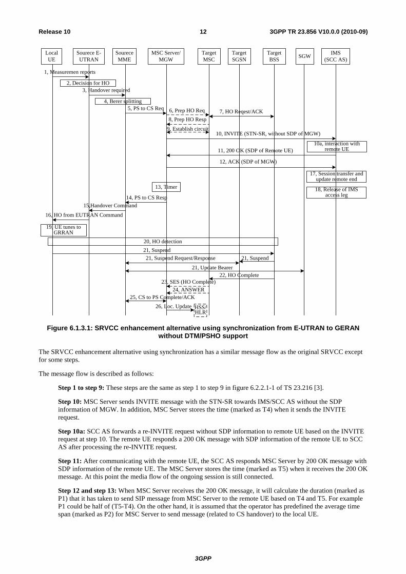
Figure 6.1.3.1: SRVCC enhancement alternative using synchronization from E-UTRAN to GERAN without DTM/PSHO support
The SRVCC enhancement alternative using synchronization has a similar message flow as the original SRVCC except for some steps.
The message flow is described as follows:
Step 1 to step 9: These steps are the same as step 1 to step 9 in figure 6.2.2.1-1 of TS 23.216 [3].
Step 10: MSC Server sends INVITE message with the STN-SR towards IMS/SCC AS without the SDP information of MGW. In addition, MSC Server stores the time (marked as T4) when it sends the INVITE request.
Step 10a: SCC AS forwards a re-INVITE request without SDP information to remote UE based on the INVITE request at step 10. The remote UE responds a 200 OK message with SDP information of the remote UE to SCC AS after processing the re-INVITE request.
Step 11: After communicating with the remote UE, the SCC AS responds MSC Server by 200 OK message with SDP information of the remote UE. The MSC Server stores the time (marked as T5) when it receives the 200 OK message. At this point the media flow of the ongoing session is still connected.
Step 12 and step 13: When MSC Server receives the 200 OK message, it will calculate the duration (marked as P1) that it has taken to send SIP message from MSC Server to the remote UE based on T4 and T5. For example P1 could be half of (T5-T4). On the other hand, it is assumed that the operator has predefined the average time span (marked as P2) for MSC Server to send message (related to CS handover) to the local UE.
3GPP
3GPP TR 23.856 V10.0.0 (2010-09)13Release 10
If P1 is larger than P2, MSC Server set up a Timer whose value is P1-P2. MSC Server will execute step 12 (send ACK message with SDP information of MGW to SCC AS) and step 13 (start the Timer) simultaneously. Only after the Timer expires, MSC Server will execute step 14 (send PS to CS Response message to MME to start CS handover).
If P2 is larger than P1, the value of the Timer will be P2-P1. MSC Server will send PS to CS Response message to MME to start CS handover and start the Timer simultaneously. Only after the Timer expires, MSC Server will send ACK message with SDP information of MGW to SCC AS. In other words, if P2 is larger than P1, step 14 will be executed after step 11, the Timer will be started after step 14, and after the Timer expires, step 12 will be executed.
If P1 is equal to P2, MSC Server will not set up the Timer and perform step 12 and step 14 simultaneously.
Step 14 to 16: These steps are the same as step 13 to step 15 in 6.2.2.1-1 of TS 23.216 [3].
Step 17 to 18: These steps are the similar to step 11 to step 12 in 6.2.2.1-1 of TS 23.216 [3]. It should be noticed that only after SCC AS receives ACK message, step 17 will be executed. At Step 17, SCC AS should forward ACK message to the remote UE based on the ACK message at step 12.
Step 19 to 26: These steps are the same as step 16 to step 23 in 6.2.2.1-1 of TS 23.216 [3].
6.1.1.4 A way using Pre-handover optimization to reduce the call drop probability
Pre-handover optimization in Annex A could be used to reduce the call drop probability. The timer in the UE may not apply here for alternative 1.
6.1.2 Sub-alternative #2 - prediction in SCC AS
6.1.2.1 Architecture Reference Model
Editor's Note: This clause will contain the architecture reference model for the enhanced SRVCC.
The key difference in this sub-alternative compared to the previous sub-alternative is that this alternative predicts the signalling delay for the remote leg update in two hops; the hop from SCC AS to the far end is measured in SCC AS and the hop from MSC Server to SCC AS is measured in MSC Server. This means this there is no need for the use of offerless INVITE with this sub-alternative. The SCC AS indicates the estimated delay to the MSC Server. The timer usage in MSC Server is similar to sub-Alternative 1, that is the MSC Server starts a timer correspondent to the estimated delays to synchronize the transfer procedures.
This sub-alternative will not change the reference architecture of original SRVCC, i.e. the architecture reference model is the same as TS 23.216 [3]. This sub-alternative requires I2 interface in the MSC Server.
This sub-alternative avoids the issues related to the offerless INVITE, i.e. the delay in overall SRVCC procedure due to three-way negotiation with the remote leg,, and possible impact to the remote UE. For the same reason, there is no need to use Alternative 3 (pre-handover optimization) with this sub-alternative, which would have an impact to the local UE. This means this sub-alternative can improve performance also with R8 SRVCC UE.
6.1.2.2 Functional Entities
Editor's Note: This clause will define the functionalities of functional entities for the enhanced SRVCC.
6.1.2.2.1 SCC AS
SCC AS should be enhanced with the following capabilities besides the functions defined in TS 23.216 [3] and TS 23.237 [4]:
1. SCC AS measures the delays in the SIP signalling in the session establishment phase. The measurement is done for each originating and terminating session which may be a subject for SRVCC. The measurement can be based on the delay between the SIP request and response in the session setup, such as UPDATE and 200 OK for UPDATE, or the 200 OK for INVITE and ACK for 200 OK. This is the estimated delay for the SIP signalling for the remote leg update, and SCC AS stores the value for each anchored session. The initial INVITE is not

3GPP
3GPP TR 23.856 V10.0.0 (2010-09)14Release 10
used for delay measurement, because the delay is significantly higher than for re-INVITE, due to paging, HSS query, etc.
Editor's Note: It is FFS whether a round trip estimate based on one sample will be adequate for the algorithm. Since the main part of the round trip time is contributed by the SIP node that processing SIP messages and the estimate does not need to be very perfect, it shoud be further checked if one round trip is enough for this alternative.
2. SCC AS returns the estimated delay to the MSC Server at the domain transfer procedure.
6.1.2.2.2 MSC Server
MSC Server should be enhanced with the following capabilities besides the functions defined in TS 23.216 [3]:
1. MSC Server shall be predefined with the average time span for itself to send the message related to CS handover to the local UE.
2. MSC Server shall be able to measure the delay from MSC Server to SCC AS in domain transfer.
3. MSC Server shall be able to receive the estimated delay from SCC AS in the domain transfer procedure, and initiate and manage a timer, which is used to synchronize the session transfer procedure and the CS handover procedure to cause the flow breaks caused by them to overlap, and so minimize the voice break.
6.1.2.3 Message Flows
Editor's Note: This clause will contain the message flows for the enhanced SRVCC.

3GPP
3GPP TR 23.856 V10.0.0 (2010-09)15Release 10
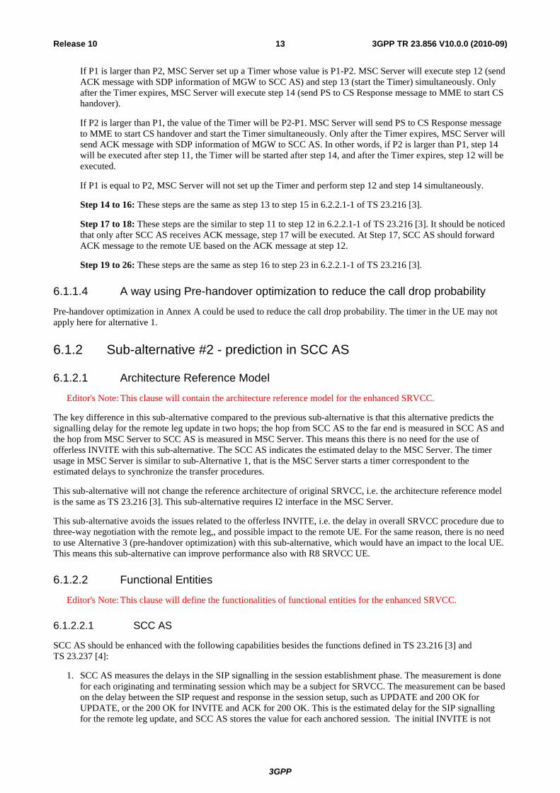
Figure 6.1.2.3.1: SRVCC enhancement alternative using synchronization from E-UTRAN to GERAN without DTM/PSHO support
The SRVCC enhancement alternative using synchronization has a similar message flow as the original SRVCC except for some steps.
The message flow is described as follows:
Prior to Step 1, the SCC AS has measured the delay in SIP signalling in the remote leg.
Step 1 to step 9: These steps are the same as step 1 to step 9 in figure 6.2.2.1-1 of TS 23.216 [3].
Step 10: MSC Server sends INVITE message with the STN-SR towards IMS/SCC AS. In addition, MSC Server stores the time (marked as T4) when it sends the INVITE request.
Step 10a: SCC AS returns the estimated delay for the remote leg update to the MSC Server.
Editor's Note: It is FFS how to ensure the message 10a is routed to the same MSC server.
Step 11: SCC AS updates the remote leg as with the current procedures in TS 23.237 [4].
Step 12: When MSC Server receives the estimated delay, it will calculate the duration that it has taken to send a SIP message from MSC Server to the SCC AS to the reception of the response which carries the estimated delay. Half of this is the signalling delay from MSC Server to SCC AS (P1). SCS AS has returned the delay from SCC AS to the remote UE (P2). On the other hand, it is assumed that the operator has predefined the average time span for MSC Server to send message (related to CS handover) to the local UE (P3). As described in clause 5 in this document, it is assumed P2+P3 is significantly longer than P1. It is further assumed here that the P2 is greater than P3+P1. The MSC starts a timer for the duration of P2-P3-P1. That is, the remote leg update (as

3GPP
3GPP TR 23.856 V10.0.0 (2010-09)16Release 10
measured by SCC AS), decreased by the predefined delay for local end transfer, decreased by the signalling delay from MSC Server to SCC AS (half of the measured round trip time). After the Timer expires, MSC Server will execute step 13 (send PS to CS Response message to MME to start CS handover). If P2 is not greater than P3+P1, the MSC Server does not start a timer but executes the Step 13 immediately.
Step 13 to 15: These steps are the same as in TS 23.216 [3].
Step 16: The remote UE receives the remote leg update and responds a 200 OK message to SCC AS after processing the re-INVITE request.
Step 17: After communicating with the remote UE, the SCC AS responds MSC Server by 200 OK message.
Step 18: The SCC AS releases the source access leg as described in TS 23.237 [4].
Step 19 to 26: These steps are the same as step 16 to step 23 in 6.2.2.1-1 of TS 23.216 [3].
As a result of the procedure, the Steps 16 and 19 should occur very close to each other.
6.2 Alternative 2 - Serial Handover
6.2.1 Architecture Reference Model The architecture model of Rel-8 SRVCC is not affected by this alternative.
6.2.2 Functional Entities The remote end and MSC server of Rel-8 SRVCC are affected by this alternative.
6.2.3 Message Flows Editor's Note: This clause will contain the message flows for the enhanced SRVCC.
Serial Handover means the RAT handover is performed after the IMS Service Continuity procedure completed. The only difference from Rel-8 SRVCC is that the MSC Server enhanced for SRVCC sends Handover response with CS resource to MME when the IMS Service Continuity Procedure is completed.
Figure 6.2.3.1: SRVCC using Serial Handover from UTRAN (HSPA) to UTRAN/GERAN
Figure 6.2.3.2 shows the main steps for serial handover. In this figure, step b1 follows step a4.
3GPP
3GPP TR 23.856 V10.0.0 (2010-09)17Release 10
Downlink
Uplink
Downlink
Uplink
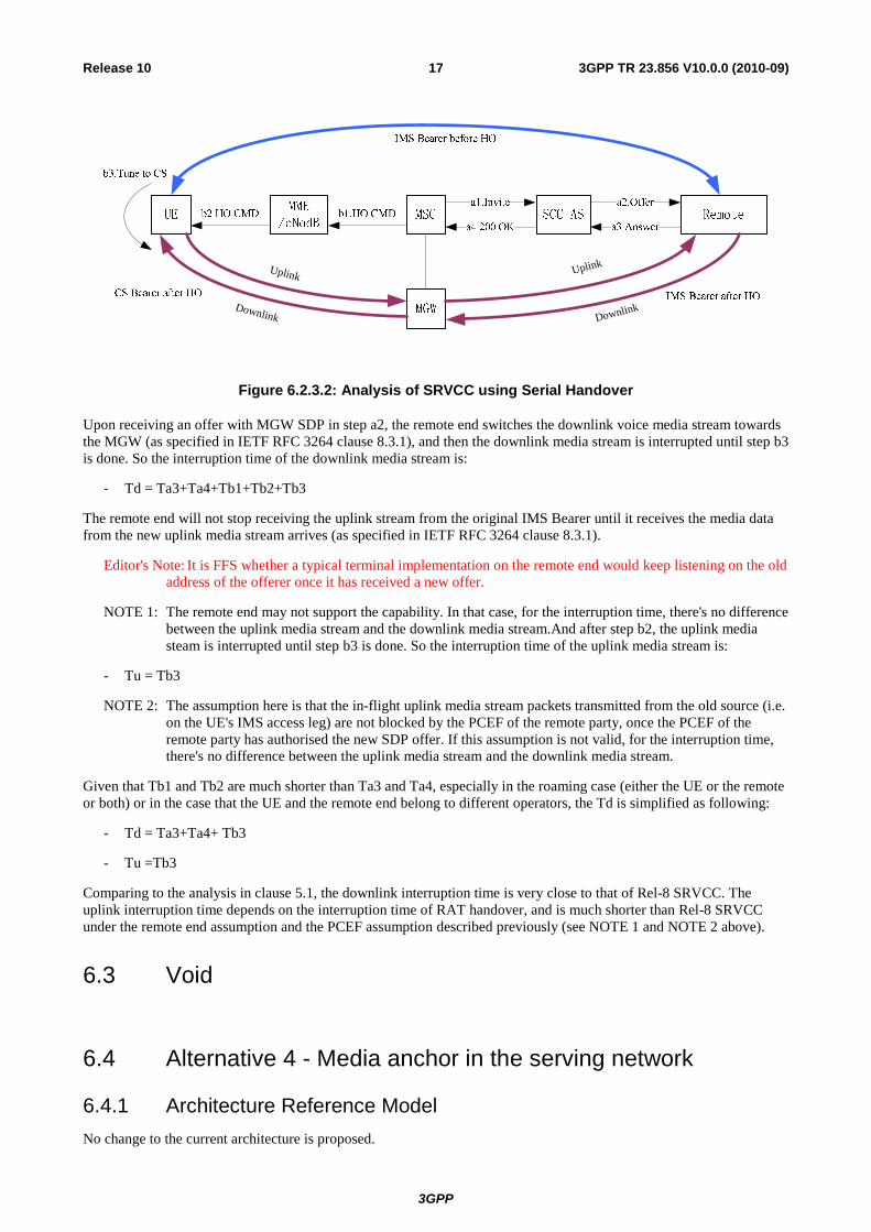
Figure 6.2.3.2: Analysis of SRVCC using Serial Handover
Upon receiving an offer with MGW SDP in step a2, the remote end switches the downlink voice media stream towards the MGW (as specified in IETF RFC 3264 clause 8.3.1), and then the downlink media stream is interrupted until step b3 is done. So the interruption time of the downlink media stream is:
- Td = Ta3+Ta4+Tb1+Tb2+Tb3
The remote end will not stop receiving the uplink stream from the original IMS Bearer until it receives the media data from the new uplink media stream arrives (as specified in IETF RFC 3264 clause 8.3.1).
Editor's Note: It is FFS whether a typical terminal implementation on the remote end would keep listening on the old address of the offerer once it has received a new offer.
NOTE 1: The remote end may not support the capability. In that case, for the interruption time, there's no difference between the uplink media stream and the downlink media stream.And after step b2, the uplink media steam is interrupted until step b3 is done. So the interruption time of the uplink media stream is:
- Tu = Tb3
NOTE 2: The assumption here is that the in-flight uplink media stream packets transmitted from the old source (i.e. on the UE's IMS access leg) are not blocked by the PCEF of the remote party, once the PCEF of the remote party has authorised the new SDP offer. If this assumption is not valid, for the interruption time, there's no difference between the uplink media stream and the downlink media stream.
Given that Tb1 and Tb2 are much shorter than Ta3 and Ta4, especially in the roaming case (either the UE or the remote or both) or in the case that the UE and the remote end belong to different operators, the Td is simplified as following:
- Td = Ta3+Ta4+ Tb3
- Tu =Tb3
Comparing to the analysis in clause 5.1, the downlink interruption time is very close to that of Rel-8 SRVCC. The uplink interruption time depends on the interruption time of RAT handover, and is much shorter than Rel-8 SRVCC under the remote end assumption and the PCEF assumption described previously (see NOTE 1 and NOTE 2 above).
6.3 Void
6.4 Alternative 4 - Media anchor in the serving network
6.4.1 Architecture Reference Model No change to the current architecture is proposed.
3GPP
3GPP TR 23.856 V10.0.0 (2010-09)18Release 10
6.4.2 Functional Entities No additional functional entities are proposed.
However, a new functionality is proposed to be defined, i.e., Visited Access Transfer Functionality (VATF), that could be handled by the MSC Server or alternatively by the P-CSCF (co-located with IMS ALG). In the following, the example usage is mainly when the VATF is handled by the MSC Server. The VATF stays in the session path for the duration of the call and it supports the MSC Server assisted mid-call feature as specified in TS 23.237 [4] for additional held sessions and conference calls with the difference that no additional information needs to be exchanged between SCC AS and MSC Server / VATF during the transfer as the session anchor is in the VATF.
6.4.3 Message Flows
6.4.3.1a Originating sessions in PS
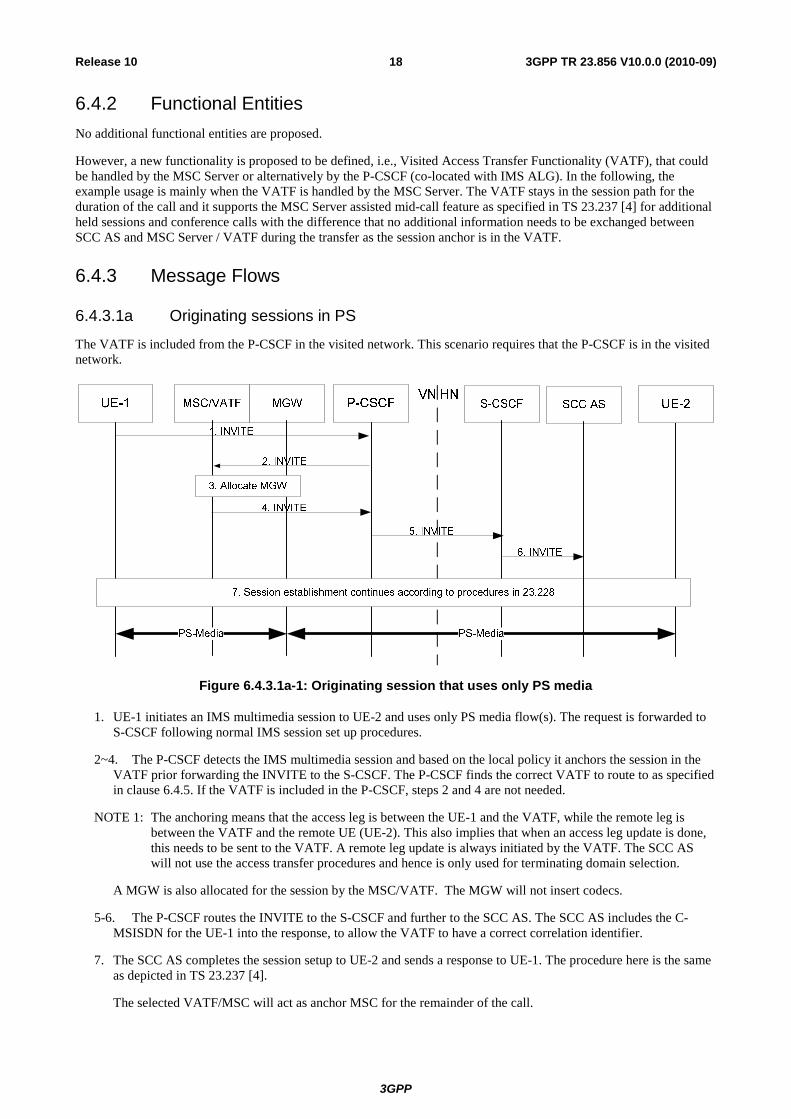
The VATF is included from the P-CSCF in the visited network. This scenario requires that the P-CSCF is in the visited network.
Figure 6.4.3.1a-1: Originating session that uses only PS media
1. UE-1 initiates an IMS multimedia session to UE-2 and uses only PS media flow(s). The request is forwarded to S-CSCF following normal IMS session set up procedures.
2~4. The P-CSCF detects the IMS multimedia session and based on the local policy it anchors the session in the VATF prior forwarding the INVITE to the S-CSCF. The P-CSCF finds the correct VATF to route to as specified in clause 6.4.5. If the VATF is included in the P-CSCF, steps 2 and 4 are not needed.
NOTE 1: The anchoring means that the access leg is between the UE-1 and the VATF, while the remote leg is between the VATF and the remote UE (UE-2). This also implies that when an access leg update is done, this needs to be sent to the VATF. A remote leg update is always initiated by the VATF. The SCC AS will not use the access transfer procedures and hence is only used for terminating domain selection.
A MGW is also allocated for the session by the MSC/VATF. The MGW will not insert codecs.
5-6. The P-CSCF routes the INVITE to the S-CSCF and further to the SCC AS. The SCC AS includes the C-MSISDN for the UE-1 into the response, to allow the VATF to have a correct correlation identifier.
7. The SCC AS completes the session setup to UE-2 and sends a response to UE-1. The procedure here is the same as depicted in TS 23.237 [4].
The selected VATF/MSC will act as anchor MSC for the remainder of the call.

3GPP
3GPP TR 23.856 V10.0.0 (2010-09)19Release 10
6.4.3.1b Termination sessions in PS
The VATF is included from the P-CSCF in the visited network. This scenario requires that the P-CSCF is in the visited network.
Figure 6.4.3.1b-1: Terminating session that uses only PS media
1. UE-2 initiates an IMS multimedia session to UE-1 and uses only PS media flow(s). The request is forwarded to S-CSCF following normal IMS session set up procedures.
2-4. The S-CSCF routes the INVITE to the SCC AS. The SCC AS performs T-ADS and then session setup continues towards P-CSCF.
5~7. The P-CSCF detects the IMS multimedia session and based on the local policy it anchors the session in the VATF. The P-CSCF finds the correct VATF to route to as specified in clause 6.4.5. If the VATF is included in the P-CSCF, steps 5 and 7 are not needed.
NOTE 1: The anchoring means that the access leg is between the UE-1 and the VATF, while the remote leg is between the VATF and the remote UE (UE-2). This also implies that when an access leg update is done, this needs to be sent to the VATF. A remote leg update is always initiated by the VATF. The SCC AS will not use the access transfer procedures and hence is only used for terminating domain selection.
A MGW is also allocated for the session by the MSC/VATF. The MGW will not insert codecs.
8. The P-CSCF routes the INVITE to UE-1 which accepts the INVITE for the bidirectional speech media.
NOTE 2: In case the UE-1 returns a response to IMS that bi-directional speech is rejected as specified in TS 23.237 in clause 6.2.2.4, the VATF will release the allocated MGW. The VATF may remove itself from the session path.
The selected VATF/MSC will act as anchor MSC for the remainder of the call.
6.4.3.2 PS – CS Access Transfer
This clause describes the main differences with existing SRVCC procedures. Some of the procedures that are not impacted have been left out for clarity of the flow. The procedure requires that the MME will select the VATF/MSC included during session establishment when establishing Sv.
3GPP
3GPP TR 23.856 V10.0.0 (2010-09)20Release 10
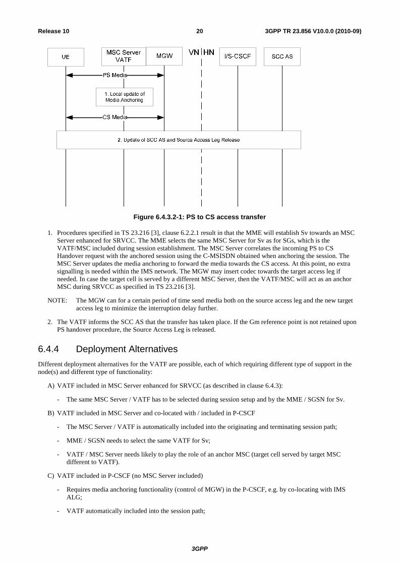
Figure 6.4.3.2-1: PS to CS access transfer
1. Procedures specified in TS 23.216 [3], clause 6.2.2.1 result in that the MME will establish Sv towards an MSC Server enhanced for SRVCC. The MME selects the same MSC Server for Sv as for SGs, which is the VATF/MSC included during session establishment. The MSC Server correlates the incoming PS to CS Handover request with the anchored session using the C-MSISDN obtained when anchoring the session. The MSC Server updates the media anchoring to forward the media towards the CS access. At this point, no extra signalling is needed within the IMS network. The MGW may insert codec towards the target access leg if needed. In case the target cell is served by a different MSC Server, then the VATF/MSC will act as an anchor MSC during SRVCC as specified in TS 23.216 [3].
NOTE: The MGW can for a certain period of time send media both on the source access leg and the new target access leg to minimize the interruption delay further.
2. The VATF informs the SCC AS that the transfer has taken place. If the Gm reference point is not retained upon PS handover procedure, the Source Access Leg is released.
6.4.4 Deployment Alternatives Different deployment alternatives for the VATF are possible, each of which requiring different type of support in the node(s) and different type of functionality:
A) VATF included in MSC Server enhanced for SRVCC (as described in clause 6.4.3):
- The same MSC Server / VATF has to be selected during session setup and by the MME / SGSN for Sv.
B) VATF included in MSC Server and co-located with / included in P-CSCF
- The MSC Server / VATF is automatically included into the originating and terminating session path;
- MME / SGSN needs to select the same VATF for Sv;
- VATF / MSC Server needs likely to play the role of an anchor MSC (target cell served by target MSC different to VATF).
C) VATF included in P-CSCF (no MSC Server included)
- Requires media anchoring functionality (control of MGW) in the P-CSCF, e.g. by co-locating with IMS ALG;
- VATF automatically included into the session path;
3GPP
3GPP TR 23.856 V10.0.0 (2010-09)21Release 10
- Session transfer request from MSC Server enhanced for SRVCC needs to be routed to VATF / P-CSCF.
Some of these deployment alternatives can also be combined with each other:
- A + B: VATF in MSC Server and in P-CSCF (with MSC Server).
- A + C: VATF in MSC Server and in P-CSCF (without MSC Server.
In these cases the MSC Server enhanced for SRVCC needs to determine whether it is having the VATF role for this session (A) and if not the session transfer requests needs to be send to the VATF (B or C).
6.4.5 Selection of VATF Selection of VATF for originated and terminated sessions
- For deployment alternatives A & B:
- Both P-CSCF and serving node (MME / SGSN) use the same (standardized) selection algorithm to find the MSC Server / VATF in the VPLMN. MME / SGSN may include selected MSC Server for Sv into the context exchange with other MME / SGSN.
- For deployment alternative C: included in P-CSCF
Selection of VATF during SRVCC:
- For deployment alternative A & B, the MME selects the MSC Server / VATF for SRVCC.
- In case of optimized call setup, both P-CSCF and serving node (MME / SGSN) use the same (standardized) selection algorithm to select the VATF in the VPLMN.
- For deployment alternative C, the MSC Server routes the session transfer request to the VATF. This can be ensured by one of the following methods:
- The MSC Server receives from the MME a visited STN-SR (vSTN-SR) that is suitable to route to the VATF. This can be achieved by one of the following methods:
- See e.g. clause 6.11 for a method to allocate the vSTN-SR during session setup, if needed, and to push the vSTN-SR from the VATF to the HSS and from there to the MME/SGSN.
- The VATF allocates the vSTN-SR when the user registers in the IMS. The vSTN-SR is provided to the IMS and via 3rd party registration to the SCC AS. The SCC AS provides the vSTN-SR to the HSS, which in turn updates the MME / SGSN.
- The MSC Server / VATF can receive the address of the P-CSCF/VATF from the IMS (e.g. during IMS registration or using an event package). This requires that the same MSC Server is selected for SGs and for Sv and that the MSC Server is enhanced for ICS.
6.4.6 Maintaining IMS registration As a prerequisite for SRVCC, the UE is IMS registered over PS. To avoid that the IMS registration expires during an ongoing voice call over GERAN / UTRAN after SRVCC, the MSC Server / VATF instructs the P-CSCF as follows:
- While the voice call is ongoing on the CS access leg (to/from the VATF), the P-CSCF shall update the local registration timer of the PS access leg such that it does not expire during the ongoing call.
- If needed, the P-CSCF will also further instruct the S-CSCF to update its registration timer for the PS access leg such that it does not expire during the ongoing call.
After releasing the voice call(s), and if needed, the UE itself updates the IMS registration, i.e., in case the original IMS registration timer on the UE has already expired, the UE will immediately perform re-registration.
NOTE: If the UE's IMS registration timer expires locally during the ongoing call, the UE ignores this until the call is completed and is able to perform a re-registration.
3GPP
3GPP TR 23.856 V10.0.0 (2010-09)22Release 10
6.5 Alternative 5 - Remote update optimization
6.5.1 Architecture Reference Model The architecture model of Rel-8 SRVCC is not affected by this alternative.
6.5.2 Functional Entities Editor's Note: This clause will define the functionalities of functional entities for the enhanced SRVCC.
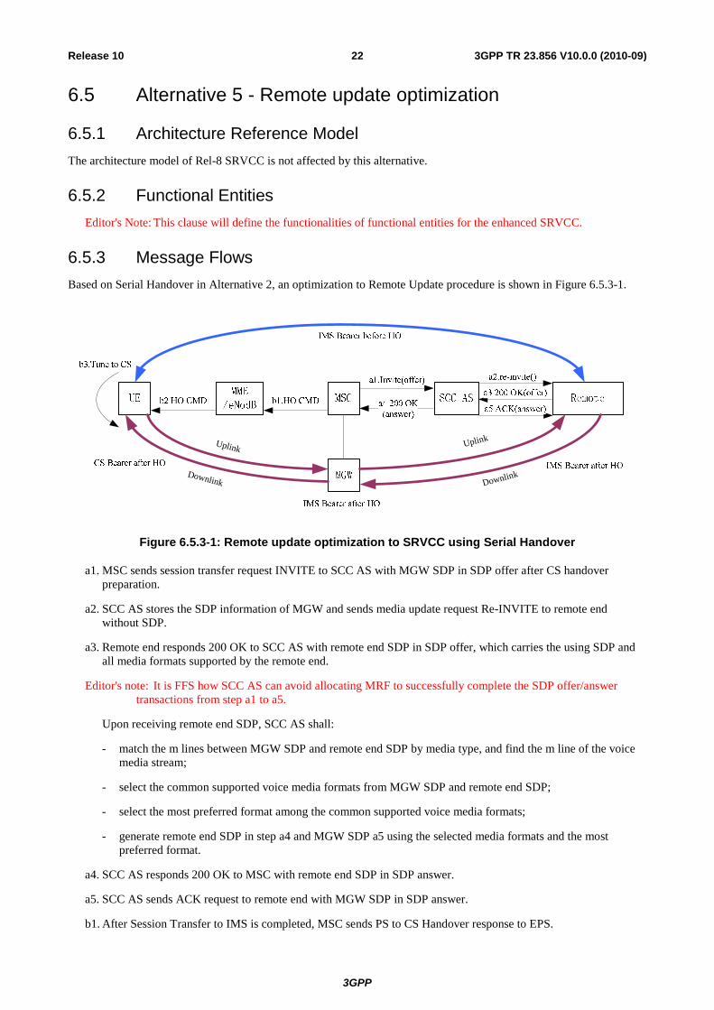
6.5.3 Message Flows Based on Serial Handover in Alternative 2, an optimization to Remote Update procedure is shown in Figure 6.5.3-1.
Downlink
Uplink
Downlink
Uplink
Figure 6.5.3-1: Remote update optimization to SRVCC using Serial Handover
a1. MSC sends session transfer request INVITE to SCC AS with MGW SDP in SDP offer after CS handover preparation.
a2. SCC AS stores the SDP information of MGW and sends media update request Re-INVITE to remote end without SDP.
a3. Remote end responds 200 OK to SCC AS with remote end SDP in SDP offer, which carries the using SDP and all media formats supported by the remote end.
Editor's note: It is FFS how SCC AS can avoid allocating MRF to successfully complete the SDP offer/answer transactions from step a1 to a5.
Upon receiving remote end SDP, SCC AS shall:
- match the m lines between MGW SDP and remote end SDP by media type, and find the m line of the voice media stream;
- select the common supported voice media formats from MGW SDP and remote end SDP;
- select the most preferred format among the common supported voice media formats;
- generate remote end SDP in step a4 and MGW SDP a5 using the selected media formats and the most preferred format.
a4. SCC AS responds 200 OK to MSC with remote end SDP in SDP answer.
a5. SCC AS sends ACK request to remote end with MGW SDP in SDP answer.
b1. After Session Transfer to IMS is completed, MSC sends PS to CS Handover response to EPS.
3GPP
3GPP TR 23.856 V10.0.0 (2010-09)23Release 10
b2. EPS sends Handover Command to UE.
b3. UE tunes to the target CS access.
The voice downlink media stream is interrupted once the remote end receives SDP answer in step a5, or the SRVCC UE performs step b3. It is restored until both step a5 and step b3 are completed. So the interruption time of the downlink media stream is:
- Td= Ta5-(Ta4+Tb1+Tb2)when step b3 is completed before remote media switching is done in step a5, i.e. Ta5>Ta4+Tb1+Tb2+Tb3; or
- Td=(Ta4+Tb1+Tb2+Tb3)-Ta5 when step b3 is done after remote media switching is done in step a5, i.e. Ta4+Tb1+Tb2>Ta5; or
- Td=Tb3 when step 3 is done in parallel with remote media switching in step a5.
So the interruption time of the downlink media stream is equal to Tb3 at the best case, and shorter than those in Rel-8 SRVCC and Alternative Serial Handover.
During remote media switching, the remote end will prepare to receive media with old format for a brief time upon receiving the SDP answer in step a5 (as specified in IETF RFC 3264 clause 8.3.2). The voice uplink media stream is interrupted after step b2, and restored after step both b3 and step a5 are done. So the interruption time of the uplink media stream is:
- Tu = Tb3
NOTE 1: The remote end may not support the capability. In that case, for the interruption time, there's no difference between the uplink media stream and the downlink media stream.
NOTE 2: The assumption here is that the in-flight uplink media stream packets transmitted from the old source (i.e. on the UE's IMS access leg) are not blocked by the PCEF of the remote party, once the PCEF of the remote party has authorised the new SDP offer. If this assumption is not valid, for the interruption time, there's no difference between the uplink media stream and the downlink media stream.
Comparing to Alternative Serial Handover, the interruption time is further optimized.
6.6 Void
6.7 Void
6.8 Alternative 8 – SR-VCC Enhancement using anchoring in the home network
6.8.1 Sub-alternative #1: MRF selective media anchoring controlled directly by the SCC AS
In this alternative, when a multimedia session is established, the SCC AS requests resources from an MRF for the voice media flow. An MRFP is then introduced in the media path between the local party and the remote one. It will act as the anchor point for the voice media flow, and the remote end will never see that change throughout the call.
When the SRVCC procedure starts, the SCC AS first instructs the MRFC to start bi-casting to the source destination point (UE-1 under LTE coverage) and to the target destination point (as described by the MGW SDP). At the time the UE has tuned to the target access, the SCC AS instructs the MRFP to stop sending media to the source access (i.e. LTE).
3GPP
3GPP TR 23.856 V10.0.0 (2010-09)24Release 10
It should be noted that the mechanism which allows the SCC AS to anchor some or all of the media in an MRFP to hide changes to the remote end and to allow for bi-casting could be useful, not only in the case of SRVCC but more generally in all session continuity and Inter-UE session cases.
NOTE: This solution has the limitation that it does not allow OMR from the visited network.
6.8.1.1 Architecture Reference Model
Editor's Note: This clause will contain the architecture reference model for the enhanced SRVCC.
UE
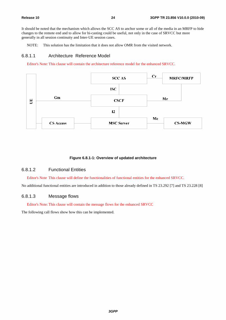
Figure 6.8.1-1: Overview of updated architecture
6.8.1.2 Functional Entities
Editor's Note This clause will define the functionalities of functional entities for the enhanced SRVCC.
No additional functional entities are introduced in addition to those already defined in TS 23.292 [7] and TS 23.228 [8]
6.8.1.3 Message flows
Editor's Note: This clause will contain the message flows for the enhanced SRVCC
The following call flows show how this can be implemented.
3GPP
3GPP TR 23.856 V10.0.0 (2010-09)25Release 10
6.8.1.3.1 Call origination
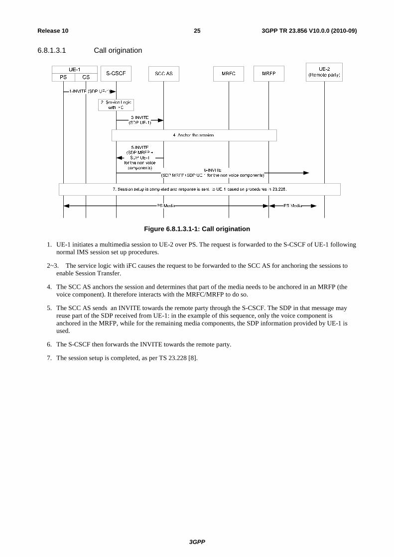
Figure 6.8.1.3.1-1: Call origination
1. UE-1 initiates a multimedia session to UE-2 over PS. The request is forwarded to the S-CSCF of UE-1 following normal IMS session set up procedures.
2~3. The service logic with iFC causes the request to be forwarded to the SCC AS for anchoring the sessions to enable Session Transfer.
4. The SCC AS anchors the session and determines that part of the media needs to be anchored in an MRFP (the voice component). It therefore interacts with the MRFC/MRFP to do so.
5. The SCC AS sends an INVITE towards the remote party through the S-CSCF. The SDP in that message may reuse part of the SDP received from UE-1: in the example of this sequence, only the voice component is anchored in the MRFP, while for the remaining media components, the SDP information provided by UE-1 is used.
6. The S-CSCF then forwards the INVITE towards the remote party.
7. The session setup is completed, as per TS 23.228 [8].
3GPP
3GPP TR 23.856 V10.0.0 (2010-09)26Release 10
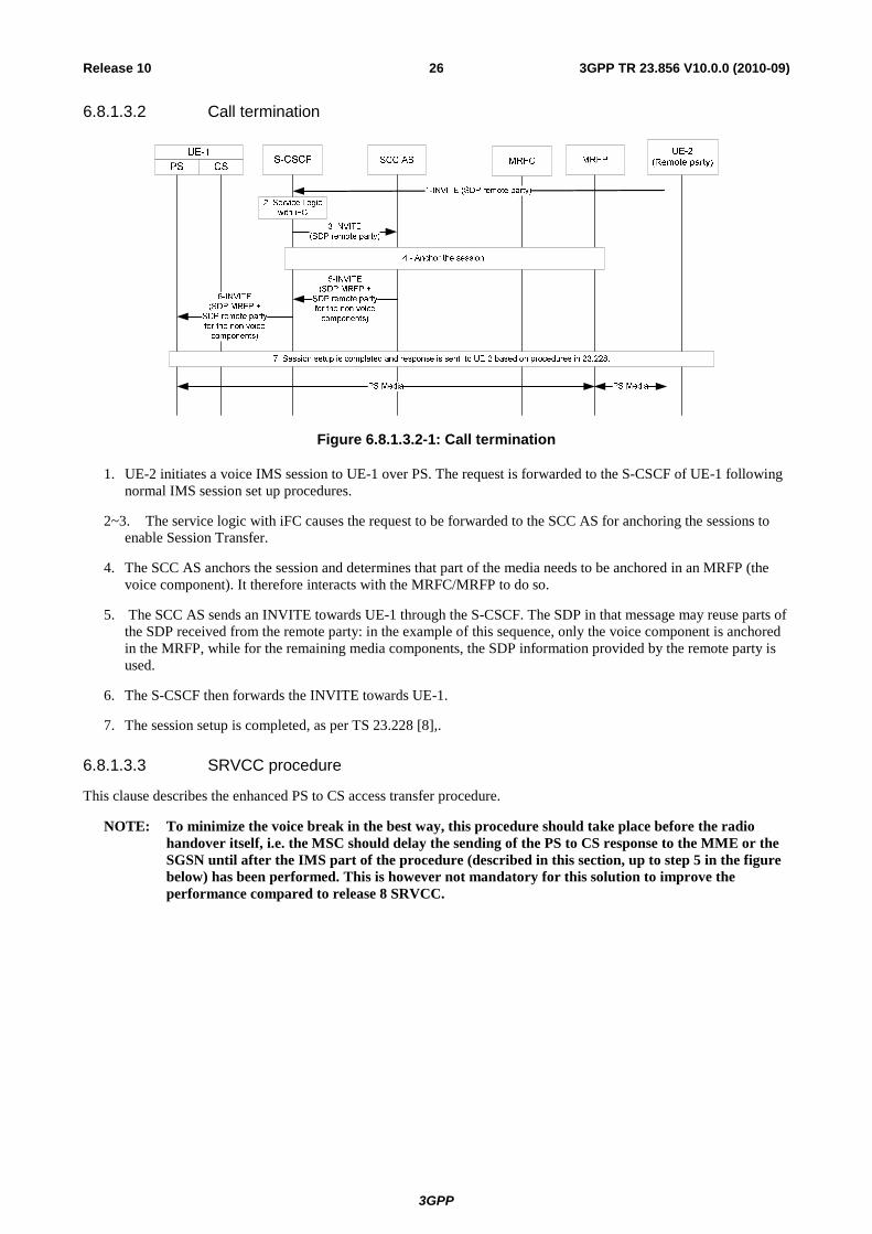
6.8.1.3.2 Call termination
Figure 6.8.1.3.2-1: Call termination
1. UE-2 initiates a voice IMS session to UE-1 over PS. The request is forwarded to the S-CSCF of UE-1 following normal IMS session set up procedures.
2~3. The service logic with iFC causes the request to be forwarded to the SCC AS for anchoring the sessions to enable Session Transfer.
4. The SCC AS anchors the session and determines that part of the media needs to be anchored in an MRFP (the voice component). It therefore interacts with the MRFC/MRFP to do so.
5. The SCC AS sends an INVITE towards UE-1 through the S-CSCF. The SDP in that message may reuse parts of the SDP received from the remote party: in the example of this sequence, only the voice component is anchored in the MRFP, while for the remaining media components, the SDP information provided by the remote party is used.
6. The S-CSCF then forwards the INVITE towards UE-1.
7. The session setup is completed, as per TS 23.228 [8],.
6.8.1.3.3 SRVCC procedure
This clause describes the enhanced PS to CS access transfer procedure.
NOTE: To minimize the voice break in the best way, this procedure should take place before the radio handover itself, i.e. the MSC should delay the sending of the PS to CS response to the MME or the SGSN until after the IMS part of the procedure (described in this section, up to step 5 in the figure below) has been performed. This is however not mandatory for this solution to improve the performance compared to release 8 SRVCC.
3GPP
3GPP TR 23.856 V10.0.0 (2010-09)27Release 10
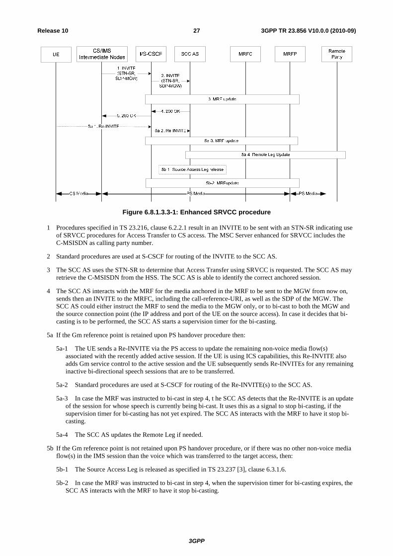
Figure 6.8.1.3.3-1: Enhanced SRVCC procedure
1 Procedures specified in TS 23.216, clause 6.2.2.1 result in an INVITE to be sent with an STN-SR indicating use of SRVCC procedures for Access Transfer to CS access. The MSC Server enhanced for SRVCC includes the C-MSISDN as calling party number.
2 Standard procedures are used at S-CSCF for routing of the INVITE to the SCC AS.
3 The SCC AS uses the STN-SR to determine that Access Transfer using SRVCC is requested. The SCC AS may retrieve the C-MSISDN from the HSS. The SCC AS is able to identify the correct anchored session.
4 The SCC AS interacts with the MRF for the media anchored in the MRF to be sent to the MGW from now on, sends then an INVITE to the MRFC, including the call-reference-URI, as well as the SDP of the MGW. The SCC AS could either instruct the MRF to send the media to the MGW only, or to bi-cast to both the MGW and the source connection point (the IP address and port of the UE on the source access). In case it decides that bi-casting is to be performed, the SCC AS starts a supervision timer for the bi-casting.
5a If the Gm reference point is retained upon PS handover procedure then:
5a-1 The UE sends a Re-INVITE via the PS access to update the remaining non-voice media flow(s) associated with the recently added active session. If the UE is using ICS capabilities, this Re-INVITE also adds Gm service control to the active session and the UE subsequently sends Re-INVITEs for any remaining inactive bi-directional speech sessions that are to be transferred.
5a-2 Standard procedures are used at S-CSCF for routing of the Re-INVITE(s) to the SCC AS.
5a-3 In case the MRF was instructed to bi-cast in step 4, t he SCC AS detects that the Re-INVITE is an update of the session for whose speech is currently being bi-cast. It uses this as a signal to stop bi-casting, if the supervision timer for bi-casting has not yet expired. The SCC AS interacts with the MRF to have it stop bi-casting.
5a-4 The SCC AS updates the Remote Leg if needed.
5b If the Gm reference point is not retained upon PS handover procedure, or if there was no other non-voice media flow(s) in the IMS session than the voice which was transferred to the target access, then:
5b-1 The Source Access Leg is released as specified in TS 23.237 [3], clause 6.3.1.6.
5b-2 In case the MRF was instructed to bi-cast in step 4, when the supervision timer for bi-casting expires, the SCC AS interacts with the MRF to have it stop bi-casting.
3GPP
3GPP TR 23.856 V10.0.0 (2010-09)28Release 10
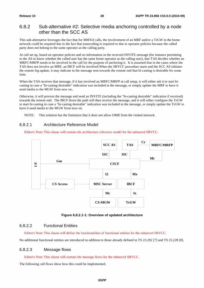
6.8.2 Sub-alternative #2: Selective media anchoring controlled by a node other than the SCC AS
This sub-alternative leverages the fact that for MMTel calls, the involvement of an MRF and/or a TrGW in the home network could be required due to the fact that transcoding is required or due to operator policies because the called party does not belong to the same operator as the calling party.
At call set up, based on operator policies and on information in the received INVITE message (for instance permitting to the AS to know whether the called user has the same home operator as the calling user), that TAS decides whether an MRFC/MRFP needs to be involved in the call for the purpose of anchoring it. It is assumed that in the cases where the TAS does not involve an MRF, an IBCF will be involved.When the SRVCC procedure starts and the SCC AS initiates the remote leg update, it may indicate in the message sent towards the remote end that bi-casting is desirable for some time.
When the TAS receives that message, if it has involved an MRFC/MRFP at call setup, it will either ask it to start bi-casting in case a "bi-casting desirable" indication was included in the message, or simply update the MRF to have it send media to the MGW from now on..
Otherwise, it will process the message and send an INVITE (including the "bi-casting desirable" indication if received) towards the remote end. The IBCF down the path will then receive the message, and it will either configure the TrGW to start bi-casting in case a "bi-casting desirable" indication was included in the message, or simply update the TrGW to have it send media to the MGW from now on.
NOTE: This solution has the limitation that it does not allow OMR from the visited network.
6.8.2.1 Architecture Reference Model
Editor's Note: This clause will contain the architecture reference model for the enhanced SRVCC.
ISC
I2
Mc
MSC Server
CSMGW
SCC AS
CSCFGm
CS Access
MRFC/MRFP
Mr
CrTAS
ISC
IBCF
TrGW
Ix
Mx
Figure 6.8.2.1-1: Overview of updated architecture
6.8.2.2 Functional Entities
Editor's Note: This clause will define the functionalities of functional entities for the enhanced SRVCC.
No additional functional entities are introduced in addition to those already defined in TS 23.292 [7] and TS 23.228 [8].
6.8.2.3 Message flows
Editor's Note: This clause will contain the message flows for the enhanced SRVCC.
The following call flows show how this could be implemented.
3GPP
3GPP TR 23.856 V10.0.0 (2010-09)29Release 10
6.8.2.3.1 Call origination
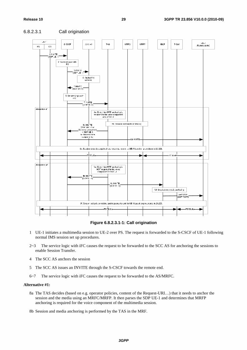
Figure 6.8.2.3.1-1: Call origination
1 UE-1 initiates a multimedia session to UE-2 over PS. The request is forwarded to the S-CSCF of UE-1 following normal IMS session set up procedures.
2~3 The service logic with iFC causes the request to be forwarded to the SCC AS for anchoring the sessions to enable Session Transfer.
4 The SCC AS anchors the session
5 The SCC AS issues an INVITE through the S-CSCF towards the remote end.
6~7 The service logic with iFC causes the request to be forwarded to the AS/MRFC.
Alternative #1:
8a The TAS decides (based on e.g. operator policies, content of the Request-URI…) that it needs to anchor the session and the media using an MRFC/MRFP. It then parses the SDP UE-1 and determines that MRFP anchoring is required for the voice component of the multimedia session.
8b Session and media anchoring is performed by the TAS in the MRF.
3GPP
3GPP TR 23.856 V10.0.0 (2010-09)30Release 10
8c~8d The TAS sends an INVITE, of which the SDP is built on the SDP received from UE-1 in step 7, and on information received from the MRF in step 8b. That INVITE message is forwarded to the remote party through the S-CSCF.
8e The session setup is completed, as per 23.228, including updating the MRF with the voice component connection information and ports for the remote party.
Alternative #2:
9a The TAS decides (based on e.g. operator policies, content of the Request-URI ...) NOT to anchor the session and the media using an MRFC/MRFP. In the example of this sequence, the basis of that decision is that the call is destined to a UE belonging to another operator, and that the signalling (resp the media) will therefore go through an IBCF (resp. a TrGW) which will be possible to use as an anchor in case of SRVCC handover.
9b~9c The TAS sends an INVITE, of which the SDP is built on the SDP received from UE-1 in step 7. That INVITE message is routed to IBCF by the S-CSCF.
9d The IBCF anchors the session and involves a TrGW for anchoring the media.
9e The IBCF sends an INVITE towards the remote party. The SDP included in that INVITE contains the information related to the TrGW as configured in step 9d.
9f The session setup is completed, as per 23.228.
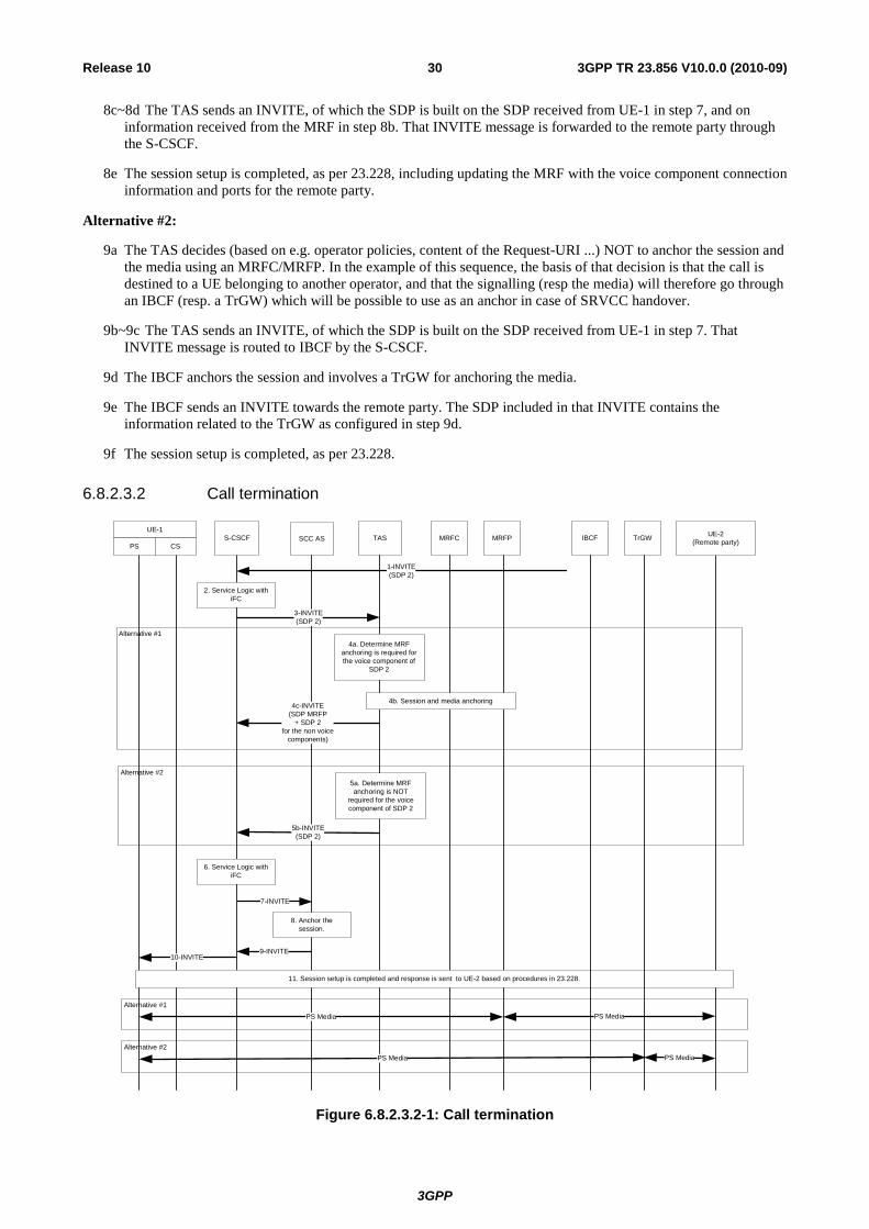
6.8.2.3.2 Call termination
Alternative #1
Alternative #2
Alternative #1
Alternative #2
SCSCF SCC ASUE1
PS CS
UE2(Remote party) MRFC
1INVITE(SDP 2)
2. Service Logic with iFC
3INVITE(SDP 2)
TAS
4cINVITE(SDP MRFP
+ SDP 2 for the non voice
components)
MRFP
4a. Determine MRF anchoring is required for the voice component of
SDP 2
4b. Session and media anchoring
5bINVITE(SDP 2)
7INVITE
6. Service Logic with iFC
PS Media PS Media
5a. Determine MRF anchoring is NOT
required for the voice component of SDP 2
8. Anchor the session.
9INVITE10INVITE
11. Session setup is completed and response is sent to UE2 based on procedures in 23.228.
IBCF TrGW
PS Media PS Media
Figure 6.8.2.3.2-1: Call termination
3GPP
3GPP TR 23.856 V10.0.0 (2010-09)31Release 10
1 UE-2 initiates a voice IMS session to UE-1 over PS. The request is forwarded to the S-CSCF of UE-1 following normal IMS session set up procedures.
2~3 The service logic with iFC causes the request to be forwarded to the TAS for providing call terminating services.
Alternative #1:
4a The TAS decides (based on e.g. operator policies, Via-header indicating that the INVITE has not traversed any node in UE-1's home network before reaching the TAS…) that it needs to anchor the session and the media using an MRFC/MRFP. It then parses the SDP2 and determines that MRFP anchoring is required for the voice component of the multimedia session.
4b Session and media anchoring is performed by the TAS in the MRF.
4c The TAS sends an INVITE, of which the SDP is built on the SDP2 received in the INVITE of step 3, and on information received from the MRF in step 4b. That INVITE message is forwarded to the remote party through the S-CSCF.
Alternative #2:
5a The TAS decides (based on e.g. operator policies, Via-header indicating that the INVITE has traversed any node in UE-1's home network before reaching the TAS …) NOT to anchor the session and the media using an MRFC/MRFP. In the example of this sequence, the basis of that decision is that the INVITE has traversed an IBCF before reaching the TAS.
5b The TAS sends an INVITE, of which the SDP is built on SDP2 received in the INVITE of step 3.
6~7 The service logic with iFC causes the request to be forwarded to the SCC AS for anchoring the sessions to enable Session Transfer.
8 The SCC AS anchors the session and decides not to involve an MRFC for anchoring the media and the session. That decision could be based on e.g. operator policies…
10~11 The INVITE is routed to UE-1 through the S-CSCF.
12 The session setup is completed, as per TS 23.228.
3GPP
3GPP TR 23.856 V10.0.0 (2010-09)32Release 10
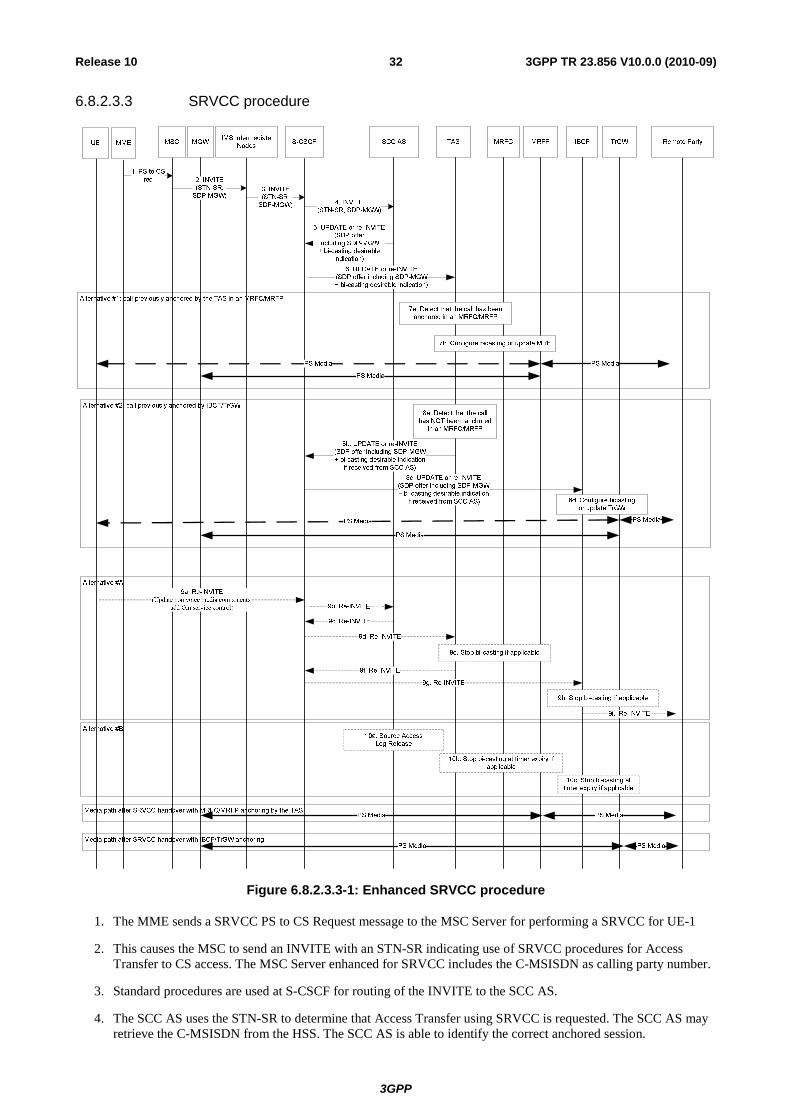
6.8.2.3.3 SRVCC procedure
Figure 6.8.2.3.3-1: Enhanced SRVCC procedure
1. The MME sends a SRVCC PS to CS Request message to the MSC Server for performing a SRVCC for UE-1
2. This causes the MSC to send an INVITE with an STN-SR indicating use of SRVCC procedures for Access Transfer to CS access. The MSC Server enhanced for SRVCC includes the C-MSISDN as calling party number.
3. Standard procedures are used at S-CSCF for routing of the INVITE to the SCC AS.
4. The SCC AS uses the STN-SR to determine that Access Transfer using SRVCC is requested. The SCC AS may retrieve the C-MSISDN from the HSS. The SCC AS is able to identify the correct anchored session.
3GPP
3GPP TR 23.856 V10.0.0 (2010-09)33Release 10
5. The SCC AS sends then a re-INVITE or UPDATE for updating the remote leg, which includes the SDP of the MGW. The SCC AS may include an indication that bi-casting would be desirable for a certain period of time for that update.
6. The message from the SCC AS is routed to the TAS by the S-CSCF based on standard IMS routing procedures.
Alternative #1: call previously anchored in an MRFC/MRFP by the TAS
7a. The TAS detects that the call has previously been anchored in an MRF.
7b If the "bi-casting desirable" indication has been received from the SCC AS, the TAS configures the bi-casting in the MRF , and starts a supervision timer for the bi-casting. If the "bi-casting desirable" indication is not included in the INVITE message received from the SCC AS, the TAS only updates the MRF to have it sent the anchored media to the MGW from this point on.
Alternative #2: call previously anchored in an IBCF/TrGW
8a ~ 8c. The TAS detects that it has not anchored the call in an MRF. It therefore processes the message, and sends an re-INVITE/UPDATE message to the S-CSCF towards the remote end. If it was received from the SCC AS, it forwards the "bi-casting desirable indication" in that message. It is routed to the IBCF as per standard IMS routing procedures.
8d. If the "bi-casting desirable" indication is included in the message received by the IBCF , the IBCF configures the bi-casting in the TrGW, and starts a supervision timer for the bi-casting. If the "bi-casting desirable" indication is not included in the message received by the IBCF, the IBCF only updates the TrGW to have it sent the anchored media to the MGW from this point on.
Alternative #A:
This scenario occurs in the case the Gm reference point is retained upon PS handover procedure. Then:
9a. The UE sends a Re-INVITE via the PS access to update the remaining non-voice media flow(s) associated with the recently added active session. If the UE is using ICS capabilities, this Re-INVITE also adds Gm service control to the active session and the UE subsequently sends Re-INVITEs for any remaining inactive bi-directional speech sessions that are to be transferred.
9b~9d. The Re-INVITE is routed to the TAS via the S-CSCF and the SCC AS.
9e. If the TAS has anchored the session in an MRF, and if it has configured bi-casting for that session due to the reception of a "bi-casting required" indication from the SCC AS, the TAS detects that the Re-INVITE is an update of the session for whose speech is currently being bi-cast. It uses this as a signal to stop bi-casting, if the supervision timer for bi-casting has not yet expired. It therefore interacts with the MRF to stop bi-casting.
9f ~9g. The TAS processes the re-INVITE and forwards it towards the remote party. That message is then routed by the S-CSCF to the IBCF.
9h. If the IBCF has configured bi-casting for that session due to the reception of a "bi-casting required" indication from the SCC AS, the IBCF detects that the Re-INVITE is an update of the session for whose speech is currently being bi-cast. It uses this as a signal to stop bi-casting, if the supervision timer for bi-casting has not yet expired. It therefore interacts with the TrGW to stop bi-casting.
9i. The IBCF processes the re-INVITE and forwards it towards the remote party.
Alternative #B:
This scenario occurs in the case the Gm reference point is not retained upon PS handover procedure. Then:
10a. The Source Access Leg is released as specified in TS 23.237 [3], clause 6.3.1.6.
10b. If the TAS has anchored the session in an MRF, and if it has configured bi-casting for that session due to the reception of a "bi-casting required" indication from the SCC AS, it stops bi-casting at the expiry of the supervision timer.
10c. If the IBCF has configured bi-casting for that session due to the reception of a "bi-casting required" indication from the SCC AS, it stops bi-casting at the expiry of the supervision timer.
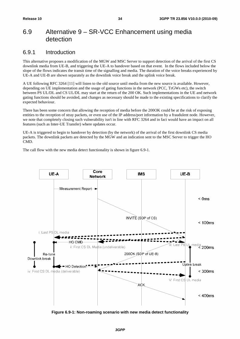
3GPP
3GPP TR 23.856 V10.0.0 (2010-09)34Release 10
6.9 Alternative 9 – SR-VCC Enhancement using media detection
6.9.1 Introduction This alternative proposes a modification of the MGW and MSC Server to support detection of the arrival of the first CS downlink media from UE-B, and triggering the UE-A to handover based on that event. In the flows included below the slope of the flows indicates the transit time of the signalling and media. The duration of the voice breaks experienced by UE-A and UE-B are shown separately as the downlink voice break and the uplink voice break.
A UE following RFC 3264 [11] will listen to the old source until media from the new source is available. However, depending on UE implementation and the usage of gating functions in the network (PCC, TrGWs etc), the switch between PS UL/DL and CS UL/DL may start at the return of the 200 OK. Such implementations in the UE and network gating functions should be avoided, and changes as necessary should be made to the existing specifications to clarify the expected behaviour.
There has been some concern that allowing the reception of media before the 200OK could be at the risk of exposing entities to the reception of stray packets, or even use of the IP address/port information by a fraudulent node. However, we note that completely closing such vulnerability isn't in line with RFC 3264 and in fact would have an impact on all features (such as Inter-UE Transfer) where updates occur.
UE-A is triggered to begin to handover by detection (by the network) of the arrival of the first downlink CS media packets. The downlink packets are detected by the MGW and an indication sent to the MSC Server to trigger the HO CMD.
The call flow with the new media detect functionality is shown in figure 6.9-1.
Figure 6.9-1: Non-roaming scenario with new media detect functionality
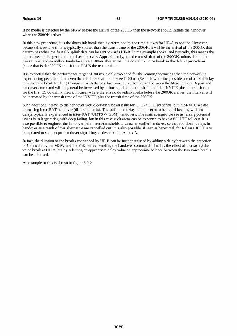
3GPP
3GPP TR 23.856 V10.0.0 (2010-09)35Release 10
If no media is detected by the MGW before the arrival of the 200OK then the network should initiate the handover when the 200OK arrives.
In this new procedure, it is the downlink break that is determined by the time it takes for UE-A to re-tune. However, because this re-tune time is typically shorter than the transit time of the 200OK, it will be the arrival of the 200OK that determines when the first CS uplink data can be sent towards UE-B. In the example above, and typically, this means the uplink break is longer than in the baseline case. Approximately, it is the transit time of the 200OK, minus the media transit time, and so will certainly be at least 100ms shorter than the downlink voice break in the default procedures (since that is the 200OK transit time PLUS the re-tune time.
It is expected that the performance target of 300ms is only exceeded for the roaming scenarios when the network is experiencing peak load, and even then the break will not exceed 400ms. (See below for the possible use of a fixed delay to reduce the break further.) Compared with the baseline procedure, the interval between the Measurement Report and handover command will in general be increased by a time equal to the transit time of the INVITE plus the transit time for the first CS downlink media. In cases where there is no downlink media before the 200OK arrives, the interval will be increased by the transit time of the INVITE plus the transit time of the 200OK.
Such additional delays to the handover would certainly be an issue for LTE -> LTE scenarios, but in SRVCC we are discussing inter-RAT handover (different bands). The additional delays do not seem to be out of keeping with the delays typically experienced in inter-RAT (UMTS -> GSM) handovers. The main scenario we see as raising potential issues is in large cities, with deep fading, but in this case such areas can be expected to have a full LTE roll-out. It is also possible to engineer the handover parameters/thresholds to cause an earlier handover, so that additional delays in handover as a result of this alternative are cancelled out. It is also possible, if seen as beneficial, for Release 10 UE's to be updated to support pre-handover signalling, as described in Annex A.
In fact, the duration of the break experienced by UE-B can be further reduced by adding a delay between the detection of CS media by the MGW and the MSC Server sending the handover command. This has the effect of increasing the voice break at UE-A, but by selecting an appropriate delay value an appropriate balance between the two voice breaks can be achieved.
An example of this is shown in figure 6.9-2.
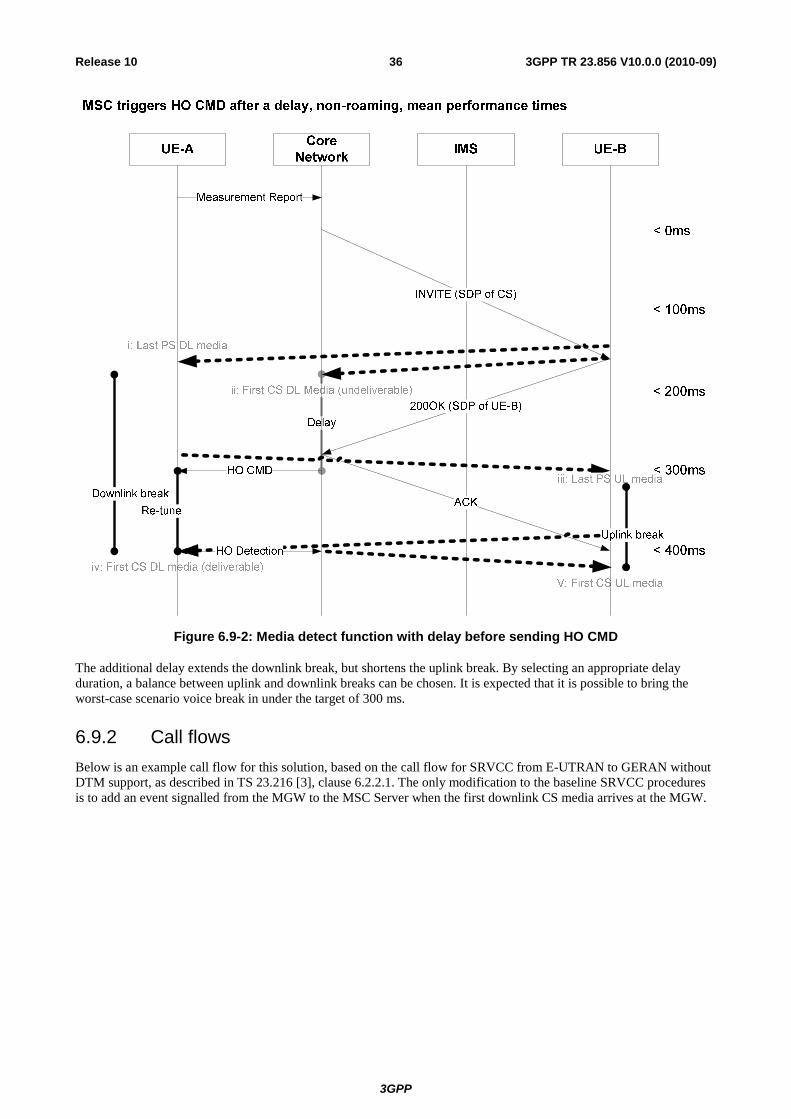
3GPP
3GPP TR 23.856 V10.0.0 (2010-09)36Release 10
Figure 6.9-2: Media detect function with delay before sending HO CMD
The additional delay extends the downlink break, but shortens the uplink break. By selecting an appropriate delay duration, a balance between uplink and downlink breaks can be chosen. It is expected that it is possible to bring the worst-case scenario voice break in under the target of 300 ms.
6.9.2 Call flows Below is an example call flow for this solution, based on the call flow for SRVCC from E-UTRAN to GERAN without DTM support, as described in TS 23.216 [3], clause 6.2.2.1. The only modification to the baseline SRVCC procedures is to add an event signalled from the MGW to the MSC Server when the first downlink CS media arrives at the MGW.
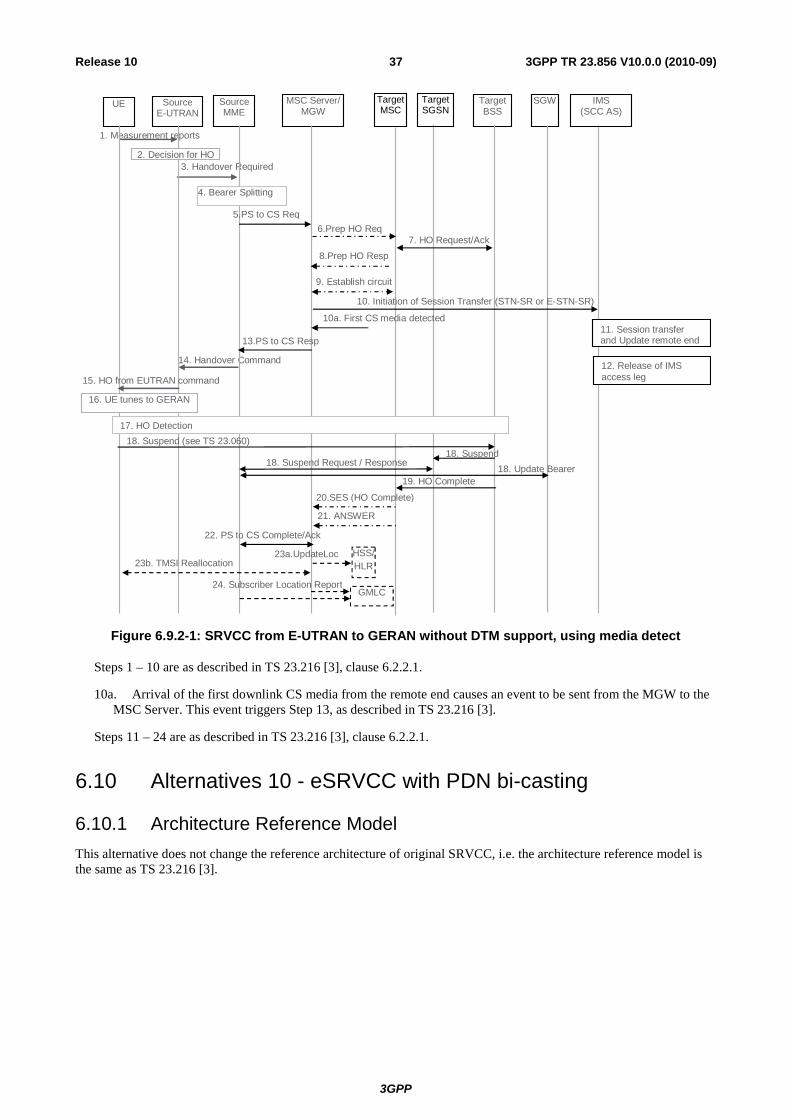
3GPP
3GPP TR 23.856 V10.0.0 (2010-09)37Release 10
UE Source E-UTRAN
Source MME
MSC Server/ MGW
Target MSC
14. Handover Command
Target BSS
1. Measurement reports
3. Handover Required
SGW
2. Decision for HO
5.PS to CS Req 6.Prep HO Req
7. HO Request/Ack 8.Prep HO Resp
9. Establish circuit
19. HO Complete
20.SES (HO Complete)
21. ANSWER
13.PS to CS Resp
15. HO from EUTRAN command
HSS/ HLR
23a.UpdateLoc
10. Initiation of Session Transfer (STN-SR or E-STN-SR)
11. Session transfer and Update remote end
IMS (SCC AS)
12. Release of IMS access leg
22. PS to CS Complete/Ack
Target SGSN
16. UE tunes to GERAN
17. HO Detection 18. Suspend (see TS 23.060)
18. Suspend 18. Suspend Request / Response
18. Update Bearer
4. Bearer Splitting
GMLC 24. Subscriber Location Report
23b. TMSI Reallocation
10a. First CS media detected
Figure 6.9.2-1: SRVCC from E-UTRAN to GERAN without DTM support, using media detect
Steps 1 – 10 are as described in TS 23.216 [3], clause 6.2.2.1.
10a. Arrival of the first downlink CS media from the remote end causes an event to be sent from the MGW to the MSC Server. This event triggers Step 13, as described in TS 23.216 [3].
Steps 11 – 24 are as described in TS 23.216 [3], clause 6.2.2.1.
6.10 Alternatives 10 - eSRVCC with PDN bi-casting
6.10.1 Architecture Reference Model This alternative does not change the reference architecture of original SRVCC, i.e. the architecture reference model is the same as TS 23.216 [3].
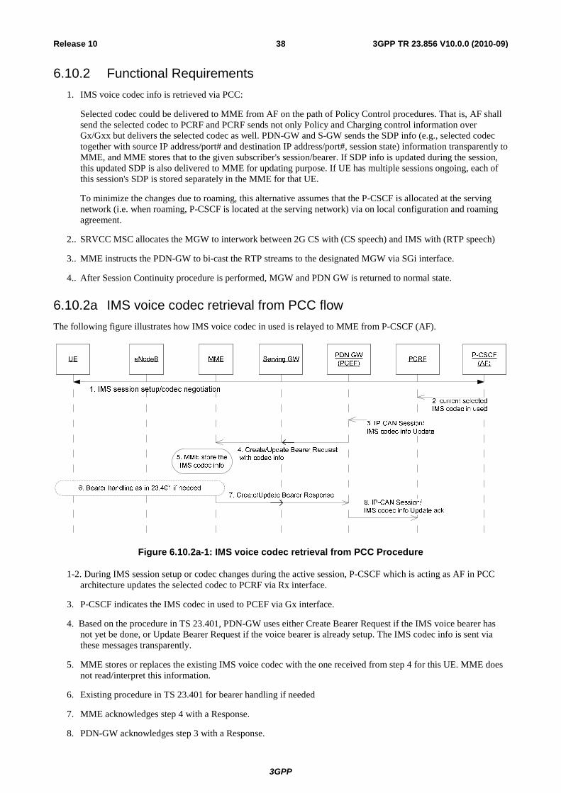
3GPP
3GPP TR 23.856 V10.0.0 (2010-09)38Release 10
6.10.2 Functional Requirements 1. IMS voice codec info is retrieved via PCC:
Selected codec could be delivered to MME from AF on the path of Policy Control procedures. That is, AF shall send the selected codec to PCRF and PCRF sends not only Policy and Charging control information over Gx/Gxx but delivers the selected codec as well. PDN-GW and S-GW sends the SDP info (e.g., selected codec together with source IP address/port# and destination IP address/port#, session state) information transparently to MME, and MME stores that to the given subscriber's session/bearer. If SDP info is updated during the session, this updated SDP is also delivered to MME for updating purpose. If UE has multiple sessions ongoing, each of this session's SDP is stored separately in the MME for that UE.
To minimize the changes due to roaming, this alternative assumes that the P-CSCF is allocated at the serving network (i.e. when roaming, P-CSCF is located at the serving network) via on local configuration and roaming agreement.
2.. SRVCC MSC allocates the MGW to interwork between 2G CS with (CS speech) and IMS with (RTP speech)
3.. MME instructs the PDN-GW to bi-cast the RTP streams to the designated MGW via SGi interface.
4.. After Session Continuity procedure is performed, MGW and PDN GW is returned to normal state.
6.10.2a IMS voice codec retrieval from PCC flow The following figure illustrates how IMS voice codec in used is relayed to MME from P-CSCF (AF).
Figure 6.10.2a-1: IMS voice codec retrieval from PCC Procedure
1-2. During IMS session setup or codec changes during the active session, P-CSCF which is acting as AF in PCC architecture updates the selected codec to PCRF via Rx interface.
3. P-CSCF indicates the IMS codec in used to PCEF via Gx interface.
4. Based on the procedure in TS 23.401, PDN-GW uses either Create Bearer Request if the IMS voice bearer has not yet be done, or Update Bearer Request if the voice bearer is already setup. The IMS codec info is sent via these messages transparently.
5. MME stores or replaces the existing IMS voice codec with the one received from step 4 for this UE. MME does not read/interpret this information.
6. Existing procedure in TS 23.401 for bearer handling if needed
7. MME acknowledges step 4 with a Response.
8. PDN-GW acknowledges step 3 with a Response.
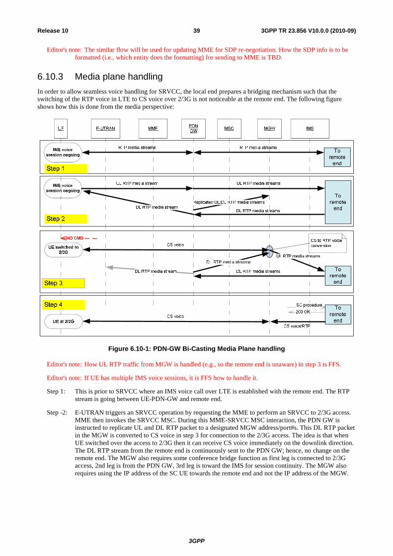
3GPP
3GPP TR 23.856 V10.0.0 (2010-09)39Release 10
Editor's note: The similar flow will be used for updating MME for SDP re-negotiation. How the SDP info is to be formatted (i.e., which entity does the formatting) for sending to MME is TBD.
6.10.3 Media plane handling In order to allow seamless voice handling for SRVCC, the local end prepares a bridging mechanism such that the switching of the RTP voice in LTE to CS voice over 2/3G is not noticeable at the remote end. The following figure shows how this is done from the media perspective:
Figure 6.10-1: PDN-GW Bi-Casting Media Plane handling
Editor's note: How UL RTP traffic from MGW is handled (e.g., so the remote end is unaware) in step 3 is FFS.
Editor's note: If UE has multiple IMS voice sessions, it is FFS how to handle it.
Step 1: This is prior to SRVCC where an IMS voice call over LTE is established with the remote end. The RTP stream is going between UE-PDN-GW and remote end.
Step -2: E-UTRAN triggers an SRVCC operation by requesting the MME to perform an SRVCC to 2/3G access. MME then invokes the SRVCC MSC. During this MME-SRVCC MSC interaction, the PDN GW is instructed to replicate UL and DL RTP packet to a designated MGW address/port#s. This DL RTP packet in the MGW is converted to CS voice in step 3 for connection to the 2/3G access. The idea is that when UE switched over the access to 2/3G then it can receive CS voice immediately on the downlink direction. The DL RTP stream from the remote end is continuously sent to the PDN GW; hence, no change on the remote end. The MGW also requires some conference bridge function as first leg is connected to 2/3G access, 2nd leg is from the PDN GW, 3rd leg is toward the IMS for session continuity. The MGW also requires using the IP address of the SC UE towards the remote end and not the IP address of the MGW.
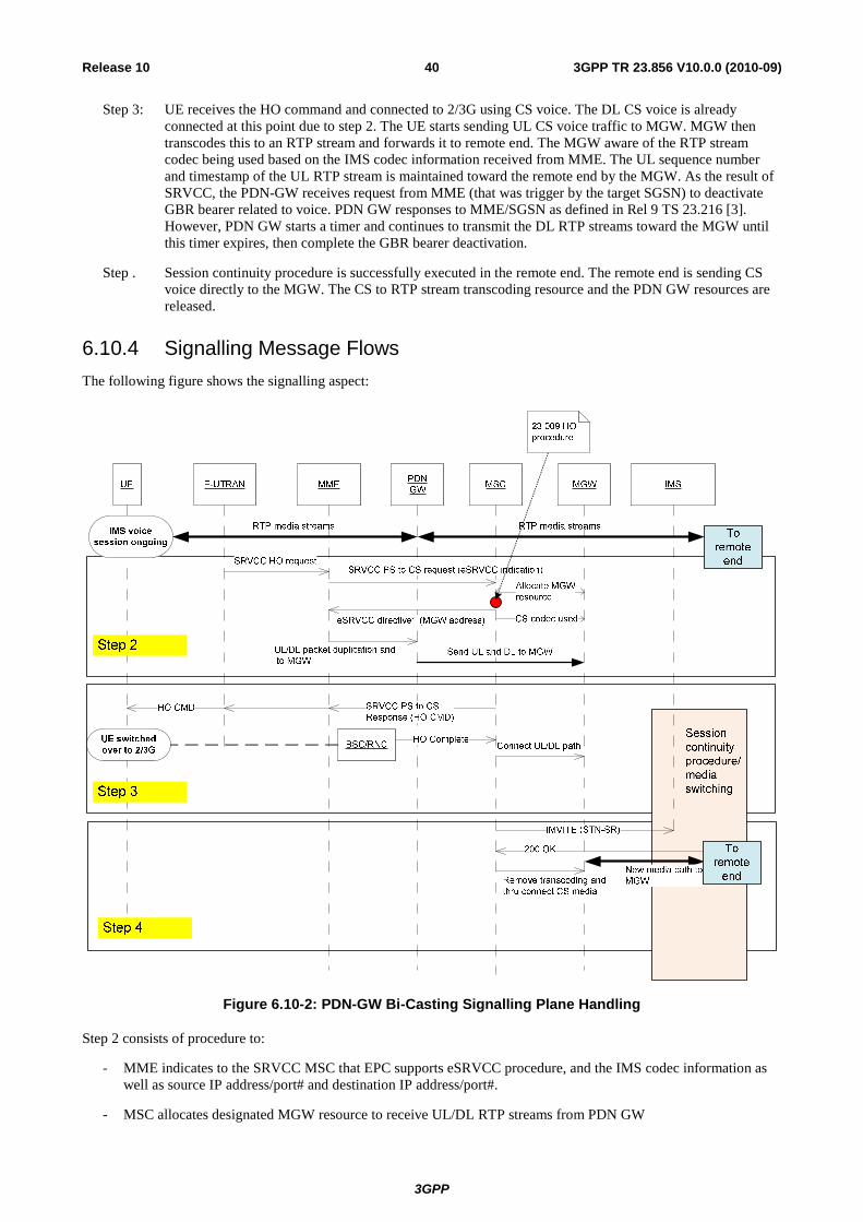
3GPP
3GPP TR 23.856 V10.0.0 (2010-09)40Release 10
Step 3: UE receives the HO command and connected to 2/3G using CS voice. The DL CS voice is already connected at this point due to step 2. The UE starts sending UL CS voice traffic to MGW. MGW then transcodes this to an RTP stream and forwards it to remote end. The MGW aware of the RTP stream codec being used based on the IMS codec information received from MME. The UL sequence number and timestamp of the UL RTP stream is maintained toward the remote end by the MGW. As the result of SRVCC, the PDN-GW receives request from MME (that was trigger by the target SGSN) to deactivate GBR bearer related to voice. PDN GW responses to MME/SGSN as defined in Rel 9 TS 23.216 [3]. However, PDN GW starts a timer and continues to transmit the DL RTP streams toward the MGW until this timer expires, then complete the GBR bearer deactivation.
Step . Session continuity procedure is successfully executed in the remote end. The remote end is sending CS voice directly to the MGW. The CS to RTP stream transcoding resource and the PDN GW resources are released.
6.10.4 Signalling Message Flows The following figure shows the signalling aspect:
Figure 6.10-2: PDN-GW Bi-Casting Signalling Plane Handling
Step 2 consists of procedure to:
- MME indicates to the SRVCC MSC that EPC supports eSRVCC procedure, and the IMS codec information as well as source IP address/port# and destination IP address/port#.
- MSC allocates designated MGW resource to receive UL/DL RTP streams from PDN GW
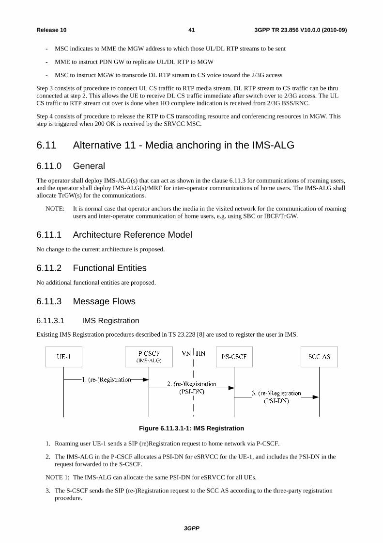
3GPP
3GPP TR 23.856 V10.0.0 (2010-09)41Release 10
- MSC indicates to MME the MGW address to which those UL/DL RTP streams to be sent
- MME to instruct PDN GW to replicate UL/DL RTP to MGW
- MSC to instruct MGW to transcode DL RTP stream to CS voice toward the 2/3G access
Step 3 consists of procedure to connect UL CS traffic to RTP media stream. DL RTP stream to CS traffic can be thru connected at step 2. This allows the UE to receive DL CS traffic immediate after switch over to 2/3G access. The UL CS traffic to RTP stream cut over is done when HO complete indication is received from 2/3G BSS/RNC.
Step 4 consists of procedure to release the RTP to CS transcoding resource and conferencing resources in MGW. This step is triggered when 200 OK is received by the SRVCC MSC.
6.11 Alternative 11 - Media anchoring in the IMS-ALG
6.11.0 General The operator shall deploy IMS-ALG(s) that can act as shown in the clause 6.11.3 for communications of roaming users, and the operator shall deploy IMS-ALG(s)/MRF for inter-operator communications of home users. The IMS-ALG shall allocate TrGW(s) for the communications.
NOTE: It is normal case that operator anchors the media in the visited network for the communication of roaming users and inter-operator communication of home users, e.g. using SBC or IBCF/TrGW.
6.11.1 Architecture Reference Model No change to the current architecture is proposed.
6.11.2 Functional Entities No additional functional entities are proposed.
6.11.3 Message Flows
6.11.3.1 IMS Registration
Existing IMS Registration procedures described in TS 23.228 [8] are used to register the user in IMS.
Figure 6.11.3.1-1: IMS Registration
1. Roaming user UE-1 sends a SIP (re)Registration request to home network via P-CSCF.
2. The IMS-ALG in the P-CSCF allocates a PSI-DN for eSRVCC for the UE-1, and includes the PSI-DN in the request forwarded to the S-CSCF.
NOTE 1: The IMS-ALG can allocate the same PSI-DN for eSRVCC for all UEs.
3. The S-CSCF sends the SIP (re-)Registration request to the SCC AS according to the three-party registration procedure.
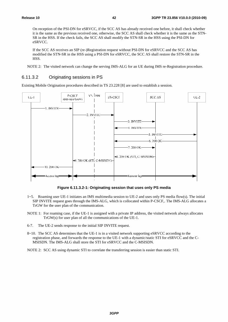
3GPP
3GPP TR 23.856 V10.0.0 (2010-09)42Release 10
On reception of the PSI-DN for eSRVCC, if the SCC AS has already received one before, it shall check whether it is the same as the previous received one, otherwise, the SCC AS shall check whether it is the same as the STN-SR in the HSS. If the check fails, the SCC AS shall modify the STN-SR in the HSS using the PSI-DN for eSRVCC.
If the SCC AS receives an SIP (re-)Registration request without PSI-DN for eSRVCC and the SCC AS has modified the STN-SR in the HSS using a PSI-DN for eSRVCC, the SCC AS shall restore the STN-SR in the HSS.
NOTE 2: The visited network can change the serving IMS-ALG for an UE during IMS re-Registration procedure.
6.11.3.2 Originating sessions in PS
Existing Mobile Origination procedures described in TS 23.228 [8] are used to establish a session.
Figure 6.11.3.2-1: Originating session that uses only PS media
1~5. Roaming user UE-1 initiates an IMS multimedia session to UE-2 and uses only PS media flow(s). The initial SIP INVITE request goes through the IMS-ALG, which is collocated within P-CSCF,. The IMS-ALG allocates a TrGW for the user plan of the communication.
NOTE 1: For roaming case, if the UE-1 is assigned with a private IP address, the visited network always allocates TrGW(s) for user plan of all the communications of the UE-1.
6-7. The UE-2 sends response to the initial SIP INVITE request.
8~10. The SCC AS determines that the UE-1 is in a visited network supporting eSRVCC according to the registration phase, and forwards the response to the UE-1 with a dynamic/static STI for eSRVCC and the C-MSISDN. The IMS-ALG shall store the STI for eSRVCC and the C-MSISDN.
NOTE 2: SCC AS using dynamic STI to correlate the transferring session is easier than static STI.

3GPP
3GPP TR 23.856 V10.0.0 (2010-09)43Release 10
6.11.3.3 Terminating sessions in PS
Existing Mobile Termination procedures described in TS 23.228 [8] are used to establish a session.
Figure 6.11.3.3-1: Terminating session that uses only PS media
1~2. UE-2 initiates an IMS multimedia session to UE-1 and uses only PS media flow(s). The initial SIP INVITE request is forwarded to SCC AS based on the service logic with iFC.
3~4. SCC AS determines that the UE-1 is in a visited network supporting eSRVCC according to the registration phase, and forwards the initial SIP INVITE request to the UE-1 with a dynamic/static STI for eSRVCC and the C-MSISDN. The IMS-ALG shall store the STI for eSRVCC and the C-MSISDN.
NOTE: SCC AS using dynamic STI to correlate the transferring session is easier than static STI.
5. The initial SIP INVITE request is forwarded to the IMS-ALG selected during the registration phase, which can be collocated within P-CSCF. the IMS-ALG allocates a TrGW for the user plan of the communication and forwards the initial SIP INVITE request to the UE-1 without the STI for eSRVCC and the C-MSISDN.
6~10. UE-1 sends a response to the initial SIP INVITE request.

3GPP
3GPP TR 23.856 V10.0.0 (2010-09)44Release 10
6.11.3.4 PS – CS Access Transfer
This clause describes the main differences with existing SRVCC procedures. Some of the procedures that are not impacted have been left out for clarity of the flow.
Figure 6.11.3.4-1: PS to CS access transfer for roaming user
1. Procedures specified in TS 23.216 [3], the MSC Server initiatesSession transfer message, e.g. by sending an initial SIP INVITE request to IMS-ALG according to the PSI-DN for eSRVCC received from the source MME. The MSC Server shall provide all the supported codecs for voice in the Session transfer message. The session transfer request is transferred via NNI interface between MSC Server and the P-CSCF
2. The IMS-ALG receives the Session transfer message and updates the access leg media segment of the session, which is correlated with the C-MSISDN.
3 The IMS-ALG sends response to the MSC Server.
NOTE: In rare case that the MSC Server does not support the codec used for the original communication, the IMS-ALG must provide transcoder for the new access leg.
4. After receiving the Session transfer message, the IMS-ALG forwards the Session transfer message, e.g. by sending an initial SIP INVITE request, to the SCC AS using the stored STI for eSRVCC.
5. The SCC AS correlates the new access signalling segment created by the Session Transfer message with the remote leg of the transferring session, and sends SIP 200 OK message to the IMS-ALG without update remote end.
6.12 Alternative 12 - HO enhancement by local anchoring with Indirect Forwarding (Merged alternative of alternatives 6 and 7)
6.12.1 Architecture Reference Model The Figure 6.12.1-1 shows the architecture reference model of this alternative.
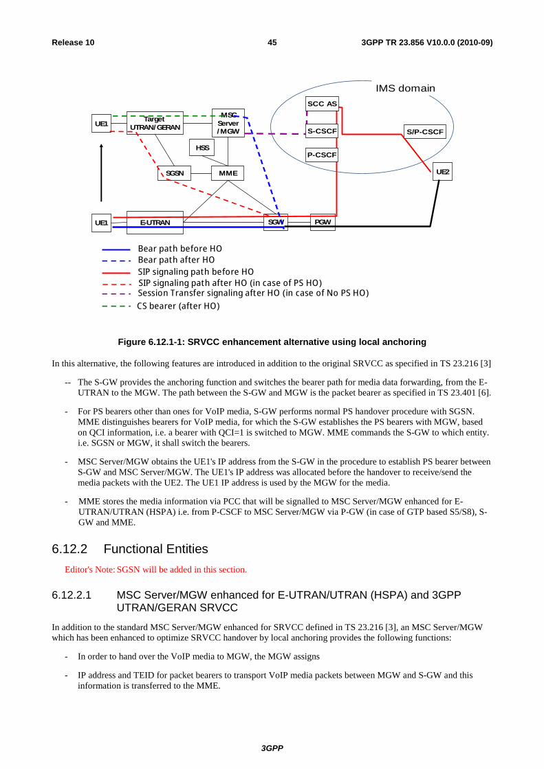
3GPP
3GPP TR 23.856 V10.0.0 (2010-09)45Release 10
UE1MSC
Server/MGW
SGSN MME
SGW
Target UTRAN/GERAN
E-UTRANUE1
HSS
Bear path before HOBear path after HOSIP signaling path before HO
UE2
PGW
Session Transfer signaling after HO (in case of No PS HO)
SCC AS
S-CSCF S/P-CSCF
P-CSCF
IMS domain
CS bearer (after HO)
SIP signaling path after HO (in case of PS HO)
Figure 6.12.1-1: SRVCC enhancement alternative using local anchoring
In this alternative, the following features are introduced in addition to the original SRVCC as specified in TS 23.216 [3]
-- The S-GW provides the anchoring function and switches the bearer path for media data forwarding, from the E-UTRAN to the MGW. The path between the S-GW and MGW is the packet bearer as specified in TS 23.401 [6].
- For PS bearers other than ones for VoIP media, S-GW performs normal PS handover procedure with SGSN. MME distinguishes bearers for VoIP media, for which the S-GW establishes the PS bearers with MGW, based on QCI information, i.e. a bearer with QCI=1 is switched to MGW. MME commands the S-GW to which entity. i.e. SGSN or MGW, it shall switch the bearers.
- MSC Server/MGW obtains the UE1's IP address from the S-GW in the procedure to establish PS bearer between S-GW and MSC Server/MGW. The UE1's IP address was allocated before the handover to receive/send the media packets with the UE2. The UE1 IP address is used by the MGW for the media.
- MME stores the media information via PCC that will be signalled to MSC Server/MGW enhanced for E-UTRAN/UTRAN (HSPA) i.e. from P-CSCF to MSC Server/MGW via P-GW (in case of GTP based S5/S8), S-GW and MME.
6.12.2 Functional Entities Editor's Note: SGSN will be added in this section.
6.12.2.1 MSC Server/MGW enhanced for E-UTRAN/UTRAN (HSPA) and 3GPP UTRAN/GERAN SRVCC
In addition to the standard MSC Server/MGW enhanced for SRVCC defined in TS 23.216 [3], an MSC Server/MGW which has been enhanced to optimize SRVCC handover by local anchoring provides the following functions:
- In order to hand over the VoIP media to MGW, the MGW assigns
- IP address and TEID for packet bearers to transport VoIP media packets between MGW and S-GW and this information is transferred to the MME.
3GPP
3GPP TR 23.856 V10.0.0 (2010-09)46Release 10
NOTE: In this alternative, MSC Server/MGW enhanced for E-UTRAN/UTRAN (HSPA) supports GTP-U protocol in addition to the support of GTP-C as specified in current SRVCC.
6.12.2.2 PCC
SDP related information such as IMS voice codec info is retrieved via PCC, which means the SDP related information is delivered to MME from AF via Policy Control procedures. That is, AF shall send SDP related information to PCRF and PCRF sends not only Policy and Charging control information over Gx/Gxx but delivers SDP related information as well. PDN-GW and S-GW sends the information transparently to MME, and MME stores that to the given subscriber's session/bearer.
6.12.2.3 MME
In addition to the standard MME behaviour defined in TS 23.401 [6], an MME which has been enhanced to optimize SR VCC handover by local anchoring provides the following functions:
- Providing the EPC bearer control function that enables to establish the EPC bearer between SGW and MGW together with other normal EPC bearers.
NOTE: This can be realized by the existing Rel8/9 GTP capability without any impact. Stage3 work will investigate the protocol impact.
- Storing the SDP related information to the given subscriber's session/bearer, and that will be signalled to MSC Server/MGW enhanced for E-UTRAN/UTRAN (HSPA) in case of SRVCC occurrence.
6.12.2.4 S-GW
In addition to the standard S-GW behaviour defined in TS 23.401 [6], an S-GW which has been enhanced to optimize SR VCC handover by local anchoring provides the following functions:
- Providing the EPC bearer control function that enables to establish the EPC bearer between SGW and MGW together with other normal EPC bearers. Note: This can be realized by the existing Rel8/9 GTP capability without any impact. Stage3 work will investigate the protocol impact.
NOTE: This can be realized by the existing Rel8/9 GTP capability without any impact. Stage3 work will investigate the protocol impact.
6.12.3 Message Flows
6.12.3.1 SRVCC Handover with PS HO support
The difference from the release 8 SRVCC is denoted with the RED font in figure 6.12.3.2-1. This procedure can be applied for the SGSN relocation procedure that might happen after UE handed over to the 3G. In this case, Source E-TRUAN and Source MME in the figure 6.12.3.2-1 can be replaced with the Source RNS and Source SGSN respectively.

3GPP
3GPP TR 23.856 V10.0.0 (2010-09)47Release 10
14. Handover Command
1. Measurement reports
3. Handover Required 2. Decision for HO
5a. PS to CS Req
18a. Reloc/HO Complete 18b. SES (HO Complete)
18c. ANSWER
13. PS to CS complete
19a. Reloc /HO Complete 19c. Modify bearer request (…, MGW IP address, TEID)
HSS/ HLR
18h. UpdateLoc
5b. Prep HO Req
8b. Prep HO Resp 8c. Establish circuit
6a. Forward Reloc Req (.., MGW IP address, TEID, TEID for data forwarding)
6d. Reloc /HO Req
5c. Reloc /HO Req
8a. Reloc /HO Req Ack 7. Forward Reloc Resp
6e. Reloc /HO Req Ack
UE SourceE -NodeB
SourceMME
MSC Server/ MGW
TargetMSC
TargetRNS/BSS Source
SGW TargetSGSN
15. HO from EUTRAN command
18d. PS to CS Complete/ Ack
19b. Forward Reloc Complete/Ack
4. Bearer Splitting
16. UE tunes to UTRAN/GERAN
P GW
Uplink and Downlink Voice traffic
MSC/MGW assigns the IP address and TEIDes for GTP tunnels for VoIP media between S-GW and MGW
Uplink and Downlink Voice traffic
Target SGW
5d. PS to CS Resp (IP address, TEID, TEID for indirect data forwarding
6b.Create session request 6c.Create session response
Down link data by indirect data forwarding(VoIP)
19d. Modify bearer response)
IMS (SCC AS)
This message is only required to establish the C-Plane between target SGSN and target S-GW in case of S-GW change, so MGW information is not necessary
6g. Create Indirect Data Forwarding Tunnel Response
6f. Create Indirect Data Forwarding Tunnel Request (…, MGW IP add, TEID for indirect data Forwarding)
7a. PS to CS Ack. (Target SGW IP address, TEID)
Down link data by indirect data forwarding (Other than VoIP)
18e. Initiation of Session Transfer (STN-SR)
18f. SCC AS starts to execute session transfer and update the remote end
18g. Session transfer has been finished and the remote end has been updated as well
Figure 6.12.3.1-1: call flow with PS HO Support
Editor's Note: The figure will be update to clarify routing will be UE-MGW-S/P-GW after step18g if step15 is performed.
Editor's Note: The line of Indirect Data Forwarding will be clarified in this figure.
Additional flow and modified nodal behaviour are explained below;
5a - 5d. When MSC Server/MGW receives the PS to CS request message from MME with the stored media information for the ongoing IMS voice session, MSC Server/MGW assigns the IP address and TEID for VoIP media and assigns the TEID for downlink indirect data forwarding from S-GW. This information is immediately returns to the MME by sending 5d message. Since the downlink indirect data forwarding function is an optional feature, MSC Server/MGW may not assign the TEID for indirect forwarding. In this case step 6f and 6g are skipped.

3GPP
3GPP TR 23.856 V10.0.0 (2010-09)48Release 10
6a. MME sets the MGW IP address, TEID and TEID for downlink indirect data forwarding together with the bearer information for EPC bearers in the forward relocation request message.
6b, 6c. If S-GW relocation needs to be executed, target SGSN sends Create session request to the target SGW with the SGSN IP address and TEID for control plane as specified in TS 23.401.
6f, 6g. Target SGSN sends Create Indirect Data Forwarding Tunnel Request for downlink data to the target SGW with the MGW IP address and TEID for downlink indirect data forwarding together with the EPC bearer information of the other PS services. The TEID for downlink indirect data forwarding is used for data forwarding from S-GW to MGW when inter RAT HO is initiated in step14 and eNodeB starts indirect data forwarding.
7a. MME sends the PS to CS Acknowledge message to MSC Server/MGW with the Target SGW IP address and TEID.
14. The source eNodeB initiates downlink data forwarding for bearers including VoIP media. From now, VoIP media is forwarded to the MGW via S-GW.
18 If MGW supports the previously used codec of the UE, the MSC-Server does not send session transfer message to the SCC AS, i.e. no remote end update procedure occurs. Otherwise, the MSC-Server initiates the remote end update procedure indicating all codec available in the MGW.
19c, 19d. When target SGSN receives the relocation complete message from target RNS/BSS, target SGSN sends the modify bearer request message to the target S-GW with the MGW IP address and TEID together with the EPC bearer information of the other PS services. The target S-GW communicates with the MSC server/MGW only for the VoIP media traffic.
After step 19c, VoIP media is conveyed between UE and peer end via the MGW.
Based on operator configuration e.g. operator policy, Session Transfer to the SCC AS can be initiated by the MSC Server/MGW at any time after step18d. In this case followings are applied:
Regarding the bearer in S-GW side, upon the completion of the session transfer procedure, VoIP bearer release procedure is to be triggered by IMS via PCC i.e. PGW/SGW/the target SGSN is to release the bearer at this point in time.
Regarding the bearer in MSC side, upon acknowledging the completion of the session transfer procedure (e.g. receiving 200 OK from SCC AS), the MSC server is to release the bearer towards SGW.
NOTE: Based on implementation, MGW should be able to decode the AMR without any re-synchronization with peer end after HO by receiving a few AMR frames.
Editor's note: If UE has multiple IMS voice sessions, it is FFS how to handle it.
6.12.3.2 SRVCC Handover without PS HO support
The difference from the release 8 SRVCC is denoted with the RED font in figure 6.12.3. 3-1. In this solution, the MSC Server/MGW behaves as the SGSN for EPC nodes in order to reduce HO disruption by adapting indirect data forwarding technique.

3GPP
3GPP TR 23.856 V10.0.0 (2010-09)49Release 10
11. Handover Command
1. Measurement reports
3. Handover Required 2. Decision for HO
5a. PS to CS Req
14a. Reloc/HO Complete 14b. SES (HO Complete)
14c. ANSWER
10. PS to CS complete
18a. Modify bearer request (MGW IP address, TEID)
HSS/ HLR
16. UpdateLoc
5b. Prep HO Req
8b. Prep HO Resp 8c. Establish circuit
5c. Reloc /HO Req
8a. Reloc /HO Req Ack
UE SourceE -NodeB
SourceMME
MSC Server/ MGW
TargetMSC
TargetRNS/BSS SGW
12. HO from EUTRAN command
14d. PS to CS Complete Ack.
4. Bearer Splitting
13. UE tunes to UTRAN/GERAN
P GW
Uplink and Downlink Voice traffic
MSC/MGW assigns the IP address and TEIDes for GTP tunnels for VoIP media between S-GW and MGW
9. Based on the media information fetched from PCC, MGW set up codec
Uplink and Downlink Voice traffic
Down link data (VoIP)
18b. Modify bearer response
IMS (SCC AS)
6g. Create Indirect Data Forwarding Tunnel Response
6f. Create Indirect Data Forwarding Tunnel Request (…, MGW IP add, TEID for indirect data Forwarding)
15c. Session transfer has been finished and the remote end has been updated as well
15a. Initiation of Session Transfer (STN-SR) 15b. SCC AS starts to execute session transfer and update the remote end
/HO Complete Reloc 17.
Figure 6.12.3.2-1: call flow without PS HO Support
Editor's Note: The figure will be update to clarify routing will be UE-MGW-S/P-GW after step15c.
Editor's Note: The line of Indirect Data Forwarding will be clarified in this figure.
Additional flow and modified nodal behaviour are explained below:
5a When MSC Server/MGW receives the PS to CS request/ Forward relocation request message from MME with the stored media information for the ongoing IMS voice session, MSC Server/MGW assigns the IP address and TEID for VoIP media and assigns the TEID for indirect forwarding from S-GW. This information is immediately returns to the MME by sending 5d message.
6f, 6g MSC Server/MGW sends Create Indirect Data Forwarding Tunnel Request to the SGW with the MGW IP address and TEID for indirect data forwarding. The TEID for indirect data forwarding is used for data forwarding from S-GW to MGW when inter RAT HO is initiated in step14.
3GPP
3GPP TR 23.856 V10.0.0 (2010-09)50Release 10
9 MGW set up the codec based on the SDP information previously fetched via PCC.
After step 11. The source eNodeB initiates Data forwarding for bearers including VoIP media. After this point, VoIP media is forwarded to the MGW via S-GW.
After step 13, the suspending related procedure is omitted in the flow since there is no change from the Rel-8 SRVCC.
14. Upon receiving step14d, MME will not trigger the release of voice bearer. The voice bearer will be deleted by IMS session transfer triggered in step15a.
15a-15c. If MGW supports the previously used codec of the UE, the MSC-Server does not send session transfer message to the SCC AS, i.e. no remote end update procedure occurs. Otherwise, the MSC-Server initiates the remote end update procedure indicating all codec available in the MGW. The MSC server/MGW initiates the Session Transfer to the SCC AS. Upon the completion of the domain transfer procedure, the VoIP media is conveyed between UE and peer end via the Target MSC directly.
18a-18b. When MSC server/MGW receives the PS to CS Complete Ack./ Forward relocation Ack message from the MME, MSC server/MGW sends the modify bearer request message to the S-GW with the MGW IP address and TEID. The S-GW communicates with the MSC server/MGW for the VoIP media traffic.
After step 18a, VoIP media is conveyed between UE and peer end via the MGW.
Regarding the bearer in S-GW side, upon the completion of the session transfer procedure, VOIP bearer release procedure is to be triggered by IMS via PCC i.e. PGW/SGW/the source MME is to release the bearer at this point in time.
Regarding the bearer in MSC side, upon acknowledging the completion of the session transfer procedure (e.g. receiving 200 OK from SCC AS), the MSC server is to release the bearer towards SGW.
NOTE: Based on implementation, MGW should be able to decode the AMR without any re-synchronization with peer end after HO by receiving a few AMR frames.
Editor's note: If UE has multiple IMS voice sessions, it is FFS how to handle it.
6.12.3.3 SRNS Relocation
When UE moves to different RNC area and SGSN relocation happens, following procedure is triggered. With this procedure, MSC Server/MGW always maintains the up-to-date information about the SGSN and S-GW. This procedure is only applied if SRVCC Handover with PS HO support is performed but remote leg update in step18e of Figure 6.12.3.2-1 is not performed.
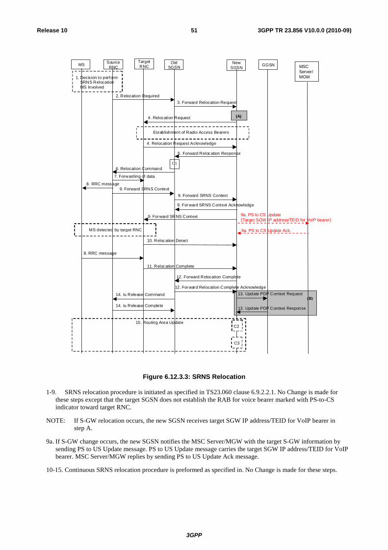
3GPP
3GPP TR 23.856 V10.0.0 (2010-09)51Release 10
GGSN
3. Forward Relocation Request
4. Relocation Request
2. Relocation Required
6. Relocation Command
5. Forward Relocation Response
4. Relocation Request Acknowledge
10. Relocation Detect
9. Forward SRNS Context 9. Forward SRNS Context
9. Forward SRNS Context
8. RRC message
8. RRC message
1. Decision to perform SRNS Rel ocation MS Involved
MS detected by target RNC
Establishment of Radio Access Bearers
C1
7. Forwarding of data
9. Forward SRNS Context Acknowledge
11. Relocation Complete
12. Forward Relocation Complete
13. Update PDP Context Request 14. Iu Release Command
14. Iu Release Complete 13. Update PDP Context Response
12. Forward Relocation Complete Acknowledge
(B)
New SGSN
Old SGSN
Target RNC
Source RNC MS
(A)
15. Routing Area Update C2
C3
9a. PS to CS Update(Target SGW IP address/TEID for VoIP bearer)
MSC Server/ MGW
9a. PS to CS Update Ack.
Figure 6.12.3.3: SRNS Relocation
1-9. SRNS relocation procedure is initiated as specified in TS23.060 clause 6.9.2.2.1. No Change is made for these steps except that the target SGSN does not establish the RAB for voice bearer marked with PS-to-CS indicator toward target RNC.
NOTE: If S-GW relocation occurs, the new SGSN receives target SGW IP address/TEID for VoIP bearer in step A.
9a. If S-GW change occurs, the new SGSN notifies the MSC Server/MGW with the target S-GW information by sending PS to US Update message. PS to US Update message carries the target SGW IP address/TEID for VoIP bearer. MSC Server/MGW replies by sending PS to US Update Ack message.
10-15. Continuous SRNS relocation procedure is preformed as specified in. No Change is made for these steps.
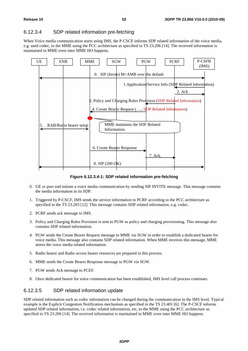
3GPP
3GPP TR 23.856 V10.0.0 (2010-09)52Release 10
6.12.3.4 SDP related information pre-fetching
When Voice media communication starts using IMS, the P-CSCF informs SDP related information of the voice media, e.g. used codec, to the MME using the PCC architecture as specified in TS 23.206 [14]. The received information is maintained in MME even inter MME HO happens.
UE P-CSFB (IMS)
PCRF
0. SIP (Invite) M=AMR over the default bearer
4. Create Bearer Request (…., SDP Related Information)
PGW SGW MME ENB
3. Policy and Charging Rules Provision (SDP Related Information)
2. Ack
5. RAB/Radio bearer setup MME maintains the SDF Related Information.
6. Create Bearer Response
7. Ack.
8. SIP (200 OK)
1.Application/Service Info (SDP Related Information)
Figure 6.12.3.4-1: SDP related information pre-fetching
0. UE or peer end initiate a voice media communication by sending SIP INVITE message. This message contains the media information in its SDP.
1. Triggered by P-CSCF, IMS sends the service information to PCRF according to the PCC architecture as specified in the TS 23.203 [12]. This message contains SDP related information, e.g. codec.
2. PCRF sends ack message to IMS.
3. Policy and Charging Rules Provision is sent to PGW as policy and charging provisioning. This message also contains SDP related information.
4. PGW sends the Create Bearer Request message to MME via SGW in order to establish a dedicated bearer for voice media. This message also contains SDP related information. When MME receives this message, MME stores the voice media related information.
5. Radio bearer and Radio access bearer resources are prepared in this process.
6. MME sends the Create Bearer Response message to PGW via SGW.
7. PGW sends Ack message to PCEF.
8. Once dedicated bearer for voice communication has been established, IMS level call process continues.
6.12.3.5 SDP related information update
SDP related information such as codec information can be changed during the communication in the IMS level. Typical example is the Explicit Congestion Notification mechanism as specified in the TS 23.401 [6]. The P-CSCF informs updated SDP related information, i.e. codec related information, etc, to the MME using the PCC architecture as specified in TS 23.206 [14]. The received information is maintained in MME even inter MME HO happens.
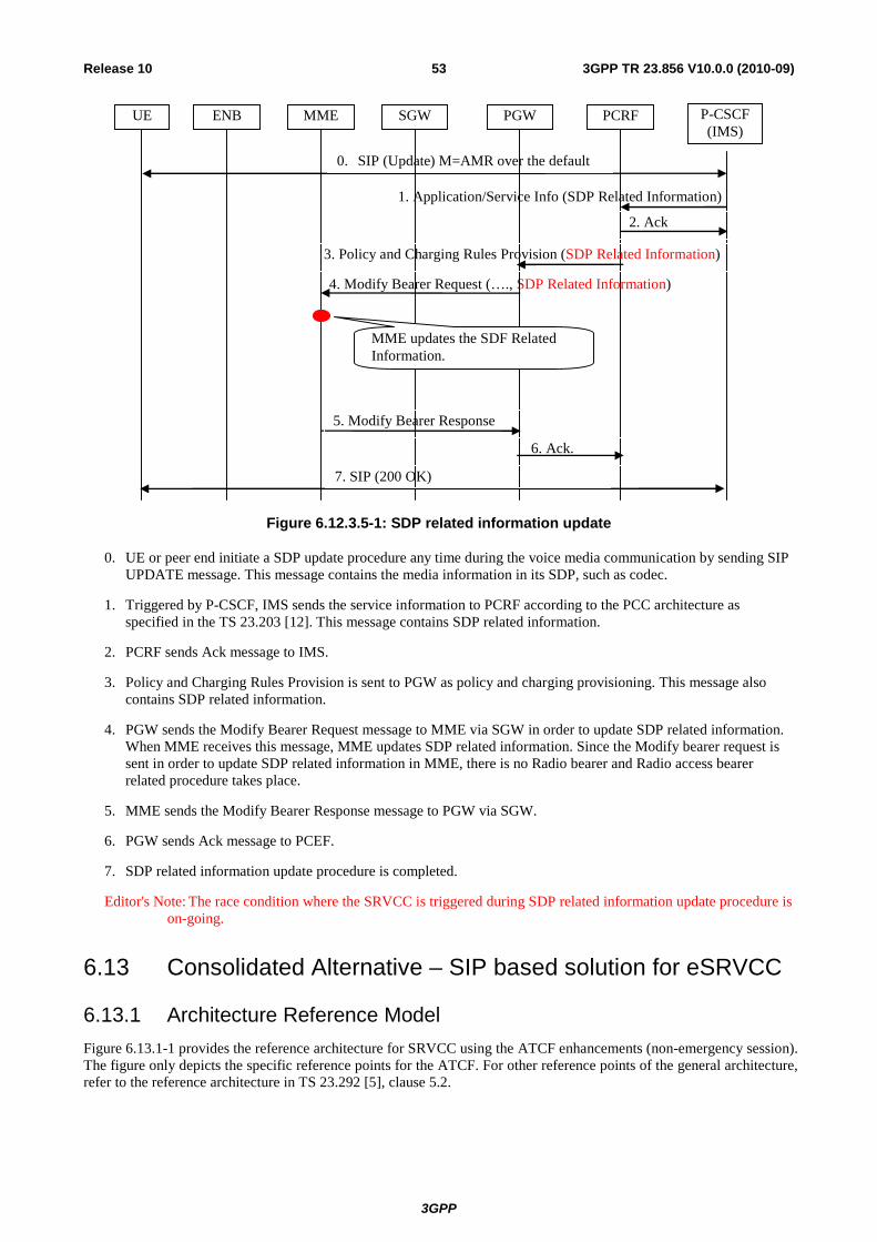
3GPP
3GPP TR 23.856 V10.0.0 (2010-09)53Release 10
UE P-CSCF (IMS)
PCRF
0. SIP (Update) M=AMR over the default bearer
1. Application/Service Info (SDP Related Information)
4. Modify Bearer Request (…., SDP Related Information)
PGW SGW MME ENB
3. Policy and Charging Rules Provision (SDP Related Information)
2. Ack
MME updates the SDF Related Information.
5. Modify Bearer Response
6. Ack.
7. SIP (200 OK)
Figure 6.12.3.5-1: SDP related information update
0. UE or peer end initiate a SDP update procedure any time during the voice media communication by sending SIP UPDATE message. This message contains the media information in its SDP, such as codec.
1. Triggered by P-CSCF, IMS sends the service information to PCRF according to the PCC architecture as specified in the TS 23.203 [12]. This message contains SDP related information.
2. PCRF sends Ack message to IMS.
3. Policy and Charging Rules Provision is sent to PGW as policy and charging provisioning. This message also contains SDP related information.
4. PGW sends the Modify Bearer Request message to MME via SGW in order to update SDP related information. When MME receives this message, MME updates SDP related information. Since the Modify bearer request is sent in order to update SDP related information in MME, there is no Radio bearer and Radio access bearer related procedure takes place.
5. MME sends the Modify Bearer Response message to PGW via SGW.
6. PGW sends Ack message to PCEF.
7. SDP related information update procedure is completed.
Editor's Note: The race condition where the SRVCC is triggered during SDP related information update procedure is on-going.
6.13 Consolidated Alternative – SIP based solution for eSRVCC
6.13.1 Architecture Reference Model Figure 6.13.1-1 provides the reference architecture for SRVCC using the ATCF enhancements (non-emergency session). The figure only depicts the specific reference points for the ATCF. For other reference points of the general architecture, refer to the reference architecture in TS 23.292 [5], clause 5.2.
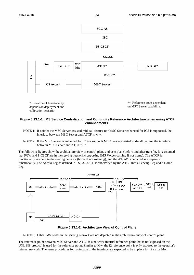
3GPP
3GPP TR 23.856 V10.0.0 (2010-09)54Release 10
ISC
MSC Server
SCC AS
ATCF*Gm
CS Access
ATGW*
I/SCSCF
Mw/Mx
PCSCF
*: Location of functionality depends on deployment and collocation scenario
Mw/Mx
Mw/I2**
**: Reference point dependent on MSC Server capability.
Figure 6.13.1-1: IMS Service Centralization and Continuity Reference Architecture when using ATCF enhancements.
NOTE 1: If neither the MSC Server assisted mid-call feature nor MSC Server enhanced for ICS is supported, the interface between MSC Server and ATCF is Mw.
NOTE 2: If the MSC Server is enhanced for ICS or supports MSC Server assisted mid-call feature, the interface between MSC Server and ATCF is I2.
The following figures show the architecture view of control plane and user plane before and after transfer. It is assumed that PGW and P-CSCF are in the serving network (supporting IMS Voice roaming if not home). The ATCF is functionality resident in the serving network (home if not roaming), and the ATGW is depicted as a separate functionality. The Access Leg as defined in TS 23.237 [4] is subdivided by the ATCF into a Serving Leg and a Home Leg.
Figure 6.13.1-2: Architecture View of Control Plane
NOTE 3: Other IMS nodes in the serving network are not depicted in the architecture view of control plane.
The reference point between MSC Server and ATCF is a network-internal reference point that is not exposed on the UNI. SIP protocol is used for the reference point. Similar to Mw, the I2 reference point is only exposed to the operator's internal network. The same procedures for protection of the interface are expected to be in place for I2 as for Mw.
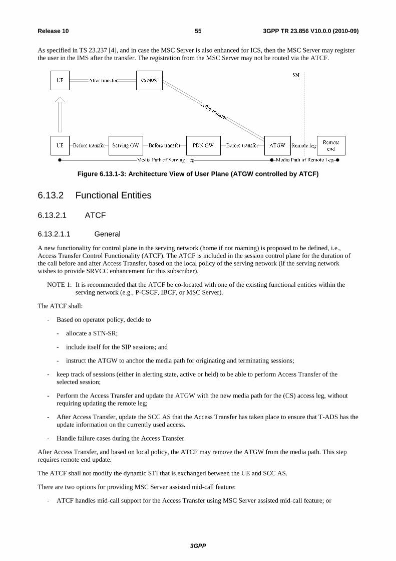
3GPP
3GPP TR 23.856 V10.0.0 (2010-09)55Release 10
As specified in TS 23.237 [4], and in case the MSC Server is also enhanced for ICS, then the MSC Server may register the user in the IMS after the transfer. The registration from the MSC Server may not be routed via the ATCF.
Figure 6.13.1-3: Architecture View of User Plane (ATGW controlled by ATCF)
6.13.2 Functional Entities
6.13.2.1 ATCF
6.13.2.1.1 General
A new functionality for control plane in the serving network (home if not roaming) is proposed to be defined, i.e., Access Transfer Control Functionality (ATCF). The ATCF is included in the session control plane for the duration of the call before and after Access Transfer, based on the local policy of the serving network (if the serving network wishes to provide SRVCC enhancement for this subscriber).
NOTE 1: It is recommended that the ATCF be co-located with one of the existing functional entities within the serving network (e.g., P-CSCF, IBCF, or MSC Server).
The ATCF shall:
- Based on operator policy, decide to
- allocate a STN-SR;
- include itself for the SIP sessions; and
- instruct the ATGW to anchor the media path for originating and terminating sessions;
- keep track of sessions (either in alerting state, active or held) to be able to perform Access Transfer of the selected session;
- Perform the Access Transfer and update the ATGW with the new media path for the (CS) access leg, without requiring updating the remote leg;
- After Access Transfer, update the SCC AS that the Access Transfer has taken place to ensure that T-ADS has the update information on the currently used access.
- Handle failure cases during the Access Transfer.
After Access Transfer, and based on local policy, the ATCF may remove the ATGW from the media path. This step requires remote end update.
The ATCF shall not modify the dynamic STI that is exchanged between the UE and SCC AS.
There are two options for providing MSC Server assisted mid-call feature:
- ATCF handles mid-call support for the Access Transfer using MSC Server assisted mid-call feature; or
3GPP
3GPP TR 23.856 V10.0.0 (2010-09)56Release 10
NOTE 2: If the ATCF supports MSC assisted mid-call feature, then the ATCF needs to keep track of sessions in alerting, active and held state to be able to support transferring one session only (either in alerting state or active, held, and / or conference call), a second already established session (which can be held and / or conference call) and / or a call in alerting state. Support of MSC Server assisted mid-call feature in the ATCF ensures that alerting state, held state, , and / or conference state can be transferred to the MSC Server without delay caused by interacting with SCC AS especially in roaming cases.
- SCC AS and ATCF handle mid-call support for the Access Transfer using MSC Server assisted mid-call feature.
NOTE 3: If the ATCF does not support the MSC assisted mid-call feature, then the ATCF needs to keep track of sessions in alerting, active and held state to be able to support transferring the first session (either in alerting state, active or held). Note that originating and terminating sessions are anchored in the ATCF/ATGW already during session setup. The SCC AS provides then session state information on alerting, held and/or conference state of the first transferred session and on second established session.
6.13.2.1.2 ATCF anchoring
The following implementation methods could be used to determine if the ATCF should be including itself at all during registration:
- If UE is roaming, based on the roaming agreement (e.g., home operator also support SRVCC enhanced with ATCF in SCC AS and HSS).
- Based on local configuration (e.g., if operator always deploys IBCF, MGCF etc. with media anchor for inter-operator calls).
- Based on registered communication service and media capabilities of the UE.
- Based on the access type over which the registration request is sent.
NOTE 1: If the ATCF decides not to include itself during registration, it will not be possible to use the ATCF enhancements during and after the registration period. The SCC AS will fall back to the Rel-9 SRVCC procedures.
The following implementation methods could be used to determine if the ATCF should anchor the media in the ATGW for an originating or terminating call:
- Based on whether the UE is roaming or not.
- Based on local configuration (e.g., if operator always deploys IBCF, MGCF etc. with media anchor for inter-operator calls).
- Based on the communication service and media capabilities used for the session.
- Based on knowledge of which network the remote party is in.
- Based on the access type over which the request or response is sent.
- Based on the SRVCC capability of the UE.
The decision to anchor media at the ATGW, during the session origination or termination, can occur either at receipt of SDP offer or after a round trip of SIP signalling with the remote party depending on the method(s) used for determining whether to anchor media or not.
6.13.2.2 ATGW
A functionality for user plane is proposed to be defined, i.e., Access Transfer Gateway (ATGW). The ATGW is controlled by the ATCF and stays in the session media path for the duration of the call and after Access Transfer, based on the local policy of the serving network. The ATGW is depicted as standalone functionality in the description, but an existing gateway can be used, i.e., only existing gateway functionality is required.
NOTE: Depending on placement of the ATCF, different physical nodes can be considered for the ATGW, e.g., IMS-AGW, TrGW, P-GW or CS-MGW. In all of these cases, the existing interfaces already support the possibility to anchor the media, and no additional extensions of protocol and interface would be needed.
3GPP
3GPP TR 23.856 V10.0.0 (2010-09)57Release 10
6.13.2.3 SCC AS
The SCC AS shall be based on the functionality specified in TS 23.237 [4], with the following enhancements:
- Correlate the dialog created by Access Transfer Update message with the remote dialog;
- Clear any existing STN-SR that has been set and provide to the HSS a
- home-network configured STN-SR if a third-party register without a STN-SR is received; or
- STN-SR received in a third-party register
- Provide the C-MSISDN and a routable Access Transfer Update - Session Transfer Identifier (ATU-STI) to the ATCF during session establishment.
- Decide whether to perform enhanced SRVCC procedure based on SRVCC capability of the UE and SRVCC subscription information that are retrieved during third party registration procedure.
- Inform the ATCF if SCC AS whether or not to anchor the media.
6.13.2.4 HSS
The HSS shall allow the SCC AS to update the user profile with a new STN-SR. In the case the ATCF is involved, the STN-SR will address the ATCF, otherwise, it will address the SCC AS.
NOTE: It is an implementation option that the HSS may store the SRVCC capability of the UE.
6.13.3 Message Flows
6.13.3.1 Selection of the ATCF
To ensure that the MSC Server selects the correct ATCF during SRVCC procedure, a routable STN-SR pointing to the ATCF shall be provided to the MME before SRVCC procedure is triggered.
The ATCF shall allocate the STN-SR when the user performs initial registration in the IMS. The STN-SR shall be provided through IMS and via third-party registration to the SCC AS. The SCC AS shall further provide the STN-SR to the HSS, which in turn shall update the MME / SGSN. The MME / SGSN will use the STN-SR in the same way as the Rel-8/9.
NOTE 1: If the SCC AS receives a third-party register without a STN-SR pointing to the ATCF, it will clear any existing STN-SR that has been set and provide a home network configured STN-SR. The SCC AS will need to ensure that the home network configured STN-SR can be restored in case of SCC AS failure (e.g., by storing it separately in the HSS as transparent data).
The following figure shows an example of IMS registration flow where the ATCF provides the STN-SR to the home network. Existing IMS Registration procedures described in TS 23.228 [8] are used to register the user in IMS.
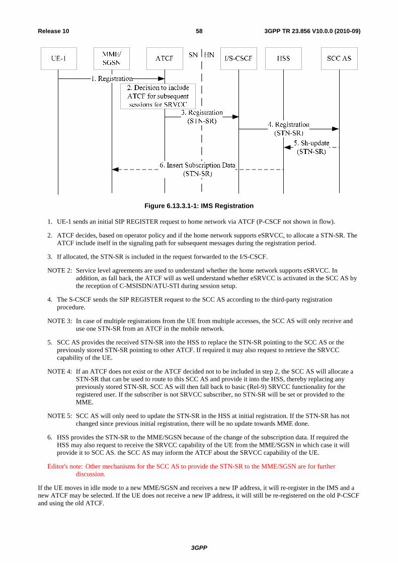
3GPP
3GPP TR 23.856 V10.0.0 (2010-09)58Release 10
Figure 6.13.3.1-1: IMS Registration
1. UE-1 sends an initial SIP REGISTER request to home network via ATCF (P-CSCF not shown in flow).
2. ATCF decides, based on operator policy and if the home network supports eSRVCC, to allocate a STN-SR. The ATCF include itself in the signaling path for subsequent messages during the registration period.
3. If allocated, the STN-SR is included in the request forwarded to the I/S-CSCF.
NOTE 2: Service level agreements are used to understand whether the home network supports eSRVCC. In addition, as fall back, the ATCF will as well understand whether eSRVCC is activated in the SCC AS by the reception of C-MSISDN/ATU-STI during session setup.
4. The S-CSCF sends the SIP REGISTER request to the SCC AS according to the third-party registration procedure.
NOTE 3: In case of multiple registrations from the UE from multiple accesses, the SCC AS will only receive and use one STN-SR from an ATCF in the mobile network.
5. SCC AS provides the received STN-SR into the HSS to replace the STN-SR pointing to the SCC AS or the previously stored STN-SR pointing to other ATCF. If required it may also request to retrieve the SRVCC capability of the UE.
NOTE 4: If an ATCF does not exist or the ATCF decided not to be included in step 2, the SCC AS will allocate a STN-SR that can be used to route to this SCC AS and provide it into the HSS, thereby replacing any previously stored STN-SR. SCC AS will then fall back to basic (Rel-9) SRVCC functionality for the registered user. If the subscriber is not SRVCC subscriber, no STN-SR will be set or provided to the MME.
NOTE 5: SCC AS will only need to update the STN-SR in the HSS at initial registration. If the STN-SR has not changed since previous initial registration, there will be no update towards MME done.
6. HSS provides the STN-SR to the MME/SGSN because of the change of the subscription data. If required the HSS may also request to receive the SRVCC capability of the UE from the MME/SGSN in which case it will provide it to SCC AS. the SCC AS may inform the ATCF about the SRVCC capability of the UE.
Editor's note: Other mechanisms for the SCC AS to provide the STN-SR to the MME/SGSN are for further discussion.
If the UE moves in idle mode to a new MME/SGSN and receives a new IP address, it will re-register in the IMS and a new ATCF may be selected. If the UE does not receive a new IP address, it will still be re-registered on the old P-CSCF and using the old ATCF.
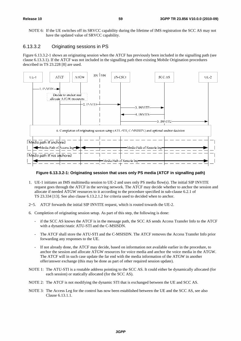
3GPP
3GPP TR 23.856 V10.0.0 (2010-09)59Release 10
NOTE 6: If the UE switches off its SRVCC capability during the lifetime of IMS registration the SCC AS may not have the updated value of SRVCC capability.
6.13.3.2 Originating sessions in PS
Figure 6.13.3.2-1 shows an originating session when the ATCF has previously been included in the signalling path (see clause 6.13.3.1). If the ATCF was not included in the signalling path then existing Mobile Origination procedures described in TS 23.228 [8] are used.
Figure 6.13.3.2-1: Originating session that uses only PS media (ATCF in signalling path)
1. UE-1 initiates an IMS multimedia session to UE-2 and uses only PS media flow(s). The initial SIP INVITE request goes through the ATCF in the serving network. The ATCF may decide whether to anchor the session and allocate if needed ATGW resources to it according to the procedure specified in sub-clause 6.2.1 of TS 23.334 [13]. See also clause 6.13.2.1.2 for criteria used to decided when to anchor.
2~5. ATCF forwards the initial SIP INVITE request, which is routed towards the UE-2.
6. Completion of originating session setup. As part of this step, the following is done:
- if the SCC AS knows the ATCF is in the message path, the SCC AS sends Access Transfer Info to the ATCF with a dynamic/static ATU-STI and the C-MSISDN.
- The ATCF shall store the ATU-STI and the C-MSISDN. The ATCF removes the Access Transfer Info prior forwarding any responses to the UE.
- If not already done, the ATCF may decide, based on information not available earlier in the procedure, to anchor the session and allocate ATGW resources for voice media and anchor the voice media in the ATGW. The ATCF will in such case update the far end with the media information of the ATGW in another offer/answer exchange (this may be done as part of other required session update).
NOTE 1: The ATU-STI is a routable address pointing to the SCC AS. It could either be dynamically allocated (for each session) or statically allocated (for the SCC AS).
NOTE 2: The ATCF is not modifying the dynamic STI that is exchanged between the UE and SCC AS.
NOTE 3: The Access Leg for the control has now been established between the UE and the SCC AS, see also Clause 6.13.1.1.

3GPP
3GPP TR 23.856 V10.0.0 (2010-09)60Release 10
6.13.3.3 Terminating sessions in PS
Figure 6.13.3.3-1 shows a terminating session when the ATCF has previously been included in the signalling path (see clause 6.13.3.1). If the ATCF was not included in the signalling path then existing Mobile Termination procedures described in TS 23.228 [8] are used.
Figure 6.13.3.2-1: Terminating session that uses only PS media (ATCF in signalling path)
1-2. A Terminating session is sent towards the roaming user UE-1 from UE-2. The initial SIP INVITE request is routed via the I/S-CSCF to the SCC AS.
3. The SCC AS performs necessary T-ADS procedures according to TS 23.237 [4], and routes the request towards the UE-1. If the SCC AS knows that the ATCF will be in the message path, the SCC AS sends Access Transfer Info to the ATCF with a dynamic/static ATU-STI and the C-MSISDN.
NOTE 1: The Access Transfer Info can be sent as part of the existing INVITE.
4. The INVITE is routed towards the ATCF. When receiving the INVITE, the ATCF may decide whether to anchor the media for the session and allocate ATGW resources for it if needed according to the procedure specified in sub-clause 6.2.1 of TS 23.334 [13]. See also clause 6.13.2.1.2 for criteria used to decided when to anchor. The ATCF shall store the ATU-STI and the C-MSISDN. The ATCF removes the ATU-STI and C-MSISDN from the INVITE.
5. The SIP INVITE is forwarded to UE-1 (P-CSCF not shown in flow).
NOTE 2: In case the UE-1 returns a response to IMS that bi-directional speech is rejected as specified in TS 23.237 [4] in clause 6.2.2.4, the ATCF will release the ATGW resources allocated if any. The ATCF may remove itself from the session path.
6. Session setup is completed. As part of this step, if not already done, the ATCF may decide, based on information not available earlier in the procedure, to anchor the session and allocate ATGW resources for voice media and anchor the voice media in the ATGW. The ATCF will in such case update the remote end with the media information of the ATGW in another offer/answer exchange (this may be done as part of other required session update).
NOTE 3: The ATCF is not modifying the dynamic STI that is exchanged between the UE and SCC AS.
NOTE 4: The Access Leg for the control has now been established between the UE and the SCC AS, see also Clause 6.13.1-1.

3GPP
3GPP TR 23.856 V10.0.0 (2010-09)61Release 10
6.13.3.4 PS-CS Access Transfer
6.13.3.4.1 PS-CS Access Transfer – ATGW anchored during session setup and supporting MSC Server assisted mid-call feature
This clause describes the main differences with existing SRVCC procedures for the case when the media is anchored in the ATGW and the ATCF enhancements are used. Some of the procedures that are not impacted have been left out for clarity of the flow.
Figure 6.13.3.4.1-1: PS to CS access transfer for roaming user
1. Interaction between UE, RAN, MME/SGSN and MSC Server as specified in TS 23.216 [3]. The following step is triggered after the MSC Server has received the PS to CS request from the MME / SGSN and has allocated resources in the RAN.
NOTE 1: In case of PS HO taking place in parallel, and according to TS 23.216 [3] clause 6.2.2.2 and clause 6.3.2.2, both the MSC Server and the target SGSN send independently the Reloc / HO Req to the target RAN. The target RAN synchronizes the PS and CS resource allocation based on information (received in transparent containers provided by the source RAN) before responding to both MSC Server and SGSN, which in turn respond to the source MME/SGSN. The source MME/SGSN will instruct the UE to move to the target RAN when having received responses from both SGSN and MSC Server.
2. The MSC Server initiates Access Transfer message according to current procedures specified in TS 23.237 [4]. Hence, and if supported, the MSC Server indicates its capability to support MSC Server assisted mid-call feature. The MSC Server provides all the supported codecs for voice in the Access Transfer message.
NOTE 2: It is expected that the CS MGW will support the codecs used for the LTE voice call, and thereby the likelihood is minimized that ATCF has to instruct the ATGW to insert codecs.
3. The ATCF receives the Access Transfer message and correlates the transferred session using the C-MSISDN. The ATCF identifies the correct anchored session and proceeds with the Access Transfer of the recently added active session. The ATCF updates the ATGW by replacing the existing PS access leg media path information with the new CS access leg media path information, by sending a Configure ATGW message to ATGW.

3GPP
3GPP TR 23.856 V10.0.0 (2010-09)62Release 10
If the MSC Server assisted mid-call feature is used, and if there are more than two sessions with speech media (at least one active), the ATCF performs the following:
- if there are two or more active sessions, selects the second-most recently active speech session, puts it on hold and releases all remaining active sessions; and
- selects the held session that has been most recently made inactive. Any other in-active sessions are released; and
- the active session together with the selected in-active session is sent in Session State Information to the MSC Server.
If the MSC Server assisted mid-call feature is used and if there are only inactive sessions (and no active session), the ATCF performs the following:
- selects the inactive session which was active most recently and releases all remaining inactive sessions; and
- includes the information that the session is inactive in the response sent to the MSC Server.
NOTE 3: The ATCF can instruct the ATGW to keep using the local port of the PS access leg media path for the new CS access leg media path.
4. The ATGW sends Configure ATGW Acknowledgment message back to ATCF.
5. The ATCF sends an Access Transfer response to the MSC Server, and in the case MSC Server assisted mid-call feature is supported and used, the ATCF provides Session State Information (SSI) in accordance to existing SRVCC procedures of TS 23.237 [4] clause 6.3.2.1.4a. The media path is switched to CS when receiving SDP information.
NOTE 4: If the ATCF instructs the ATGW to use the local port of the PS access leg media path for the new CS access leg media path, the Access Transfer response can be sent right after step 3.
NOTE 5: Since step 2 to 5 are in parallel to step 1, the voice break interruption starts when either the media is switched to the CS MGW controlled by the MSC Server enhanced for SRVCC or when the UE starts to relocate to the target (whatever comes first). The voice break interruption ends when the UE has tuned to the target and media has switched to CS MGW (whatever comes last). It is assumed that the media is switched to CS MGW during the time the UE tunes to target.
6. After receiving the Access Transfer message, the ATCF re-establishes the communication with the SCC AS and updates the SCC AS that the transfer has taken place by sending an Access Transfer Update message to the SCC AS using the stored ATU-STI. The Access Transfer Update creates a new dialogue between the ATCF and SCC AS. The SCC AS correlates the new dialog with the remote dialog. As there is no update in the session description, no remote end update will be sent by the SCC AS.
NOTE 6: The new dialog between ATCF and SCC AS is needed to replace the old dialog that has been setup over the PS access leg (and registration) and to complete the access transfer in the SCC AS. This is to ensure that if the PS registration for the user expires, the new home leg will not be released / affected.
7. The SCC AS sends confirmation response to the ATCF.
8. If the MSC Server receives the Session State Information of more than one active or inactive speech sessions, it initiates Access Transfer towards ATCF then to SCC AS for the additional session. The transfer procedure is similar as the transfer of the first session.
NOTE 7: Step 8 is performed independently of step 6 and 7.
NOTE 8: The Access Leg for the control has moved over to the CS access.
9. Procedures as defined in TS 23.237 [4] are used to handle the cases that the Gm reference point is retained upon PS handover procedure, not retained upon PS handover or if there was no other voice-media flow(s) in the IMS session.

3GPP
3GPP TR 23.856 V10.0.0 (2010-09)63Release 10
6.13.3.4.2 PS-CS Access Transfer – ATGW anchored during session setup and MSC Server assisted mid-call feature supported by SCC AS
This clause describes the main differences with existing SRVCC procedures for the case when the media is anchored in the ATGW and the ATCF enhancements are used. Some of the procedures that are not impacted have been left out for clarity of the flow.
Figure 6.13.3.4.2-1: PS to CS access transfer for roaming user
1. Interaction between UE, RAN, MME/SGSN and MSC Server as specified in TS 23.216 [3]. The following step is triggered after the MSC Server has received the PS to CS request from the MME / SGSN and has allocated resources in the RAN.
NOTE 1: In case of PS HO taking place in parallel, and according to TS 23.216 [3] clause 6.2.2.2 and clause 6.3.2.2, both the MSC Server and the target SGSN send independently the Reloc / HO Req to the target RAN. The target RAN synchronizes the PS and CS resource allocation based on information (received in transparent containers provided by the source RAN) before responding to both MSC Server and SGSN, which in turn respond to the source MME/SGSN. The source MME/SGSN will instruct the UE to move to the target RAN when having received responses from both SGSN and MSC Server.
2. The MSC Server initiates Access Transfer message according to current procedures specified in TS 23.237 [4]. Hence, and if supported, the MSC Server indicates its capability to support MSC Server assisted mid-call feature. The MSC Server provides all the supported codecs for voice in the Access Transfer message.
NOTE 2: It is expected that the CS MGW will support the codecs used for the LTE voice call, and thereby the likelihood is minimized that ATCF has to instruct the ATGW to insert codecs.
3. The ATCF receives the Access Transfer message and correlates the transferred session using the C-MSISDN. The ATCF identifies the correct anchored session and proceeds with the Access Transfer of the most recently active session. The ATCF updates the ATGW by replacing the existing PS access leg media path information with the new CS access leg media path information, by sending a Configure ATGW message to ATGW.
NOTE 3: The ATCF may instruct the ATGW to keep using the local port of the PS access leg media path for the new CS access leg media path.
4. The ATGW sends Configure ATGW Acknowledgment message back to ATCF.
5. The ATCF sends an Access Transfer response to the MSC Server. The media path is switched to CS when receiving SDP information.
3GPP
3GPP TR 23.856 V10.0.0 (2010-09)64Release 10
NOTE 4: If the ATCF instructs the ATGW to use the local port of the PS access leg media path for the new CS access leg media path, the Access Transfer response can be sent right after step 3.
NOTE 5: Since step 2 to 5 are in parallel to step 1, the voice break interruption starts when either the media is switched to the CS MGW controlled by the MSC Server enhanced for SRVCC or when the UE starts to relocate to the target (whatever comes first). The voice break interruption ends when the UE has tuned to the target and media has switched to CS MGW (whatever comes last). It is assumed that the media is switched to CS MGW during the time the UE tunes to target.
6. After receiving the Access Transfer message, the ATCF re-establish the communication with the SCC AS and updates the SCC AS that the transfer has taken place by sending an Access Transfer Update message to the SCC AS using the stored ATU-STI. If the MSC server indicated it supported mid-call feature, it also indicates this in the message to the SCC AS. The Access Transfer Update creates a new dialogue between the ATCF and SCC AS. The SCC AS correlates the new dialog with the remote dialog (e.g., using the C-MSISDN). As there is no update in the session description, no remote end update will be sent.
NOTE 6: The new dialog between ATCF and SCC AS is needed to replace the old dialog that has been setup over the PS access leg (and registration). This is to ensure that if the PS registration for the user expires, the new home leg will not be released / affected.
7. The SCC AS sends confirmation response to the ATCF. If the SCC AS and MSC supports mid call feature, the SCC AS provides the SSI according to TS 23.237 [4] clause 6.3.2.1.4a.
NOTE 7: The SSI information is in stage 3 provided by a REFER message that is separate from the 200 OK sent as confirmation response to the Invite, i.e., step 7 will in practice be two messages. One 200 OK and one REFER.
8. The ATCF forwards the SSI to the MSC server.
9. If the MSC Server receives the Session State Information of more than one active or inactive speech sessions, it initiates Access Transfer towards SCC AS for the additional session.
NOTE 8: The Access Leg for the control has moved over to the CS access.
10. Procedures as defined in TS 23.237 [4] are used to handle the cases that the Gm reference point is retained upon PS handover procedure, not retained upon PS handover or if there was no other voice-media flow(s) in the IMS session.
6.13.3.4.3 PS-CS Access Transfer – ATCF not included during registration
If the decision by the ATCF during registration was not to be included at all, the SRVCC procedures will fall back to Rel-9 procedures according to TS 23.237 [4] clauses 6.3.2.1.4 and 6.3.2.1.4a.
6.13.3.4.4 PS-CS Access Transfer – ATGW not anchored during session setup
This clause describes the main differences with existing SRVCC procedures for the case when the ATCF is included in the session path, but media has not been anchored in ATGW. Some of the procedures that are not impacted have been left out for clarity of the flow.
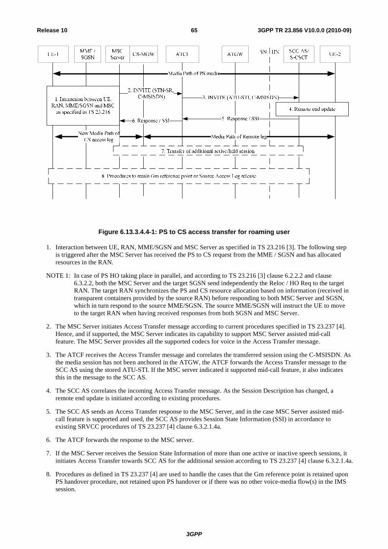
3GPP
3GPP TR 23.856 V10.0.0 (2010-09)65Release 10
Figure 6.13.3.4.4-1: PS to CS access transfer for roaming user
1. Interaction between UE, RAN, MME/SGSN and MSC Server as specified in TS 23.216 [3]. The following step is triggered after the MSC Server has received the PS to CS request from the MME / SGSN and has allocated resources in the RAN.
NOTE 1: In case of PS HO taking place in parallel, and according to TS 23.216 [3] clause 6.2.2.2 and clause 6.3.2.2, both the MSC Server and the target SGSN send independently the Reloc / HO Req to the target RAN. The target RAN synchronizes the PS and CS resource allocation based on information (received in transparent containers provided by the source RAN) before responding to both MSC Server and SGSN, which in turn respond to the source MME/SGSN. The source MME/SGSN will instruct the UE to move to the target RAN when having received responses from both SGSN and MSC Server.
2. The MSC Server initiates Access Transfer message according to current procedures specified in TS 23.237 [4]. Hence, and if supported, the MSC Server indicates its capability to support MSC Server assisted mid-call feature. The MSC Server provides all the supported codecs for voice in the Access Transfer message.
3. The ATCF receives the Access Transfer message and correlates the transferred session using the C-MSISDN. As the media session has not been anchored in the ATGW, the ATCF forwards the Access Transfer message to the SCC AS using the stored ATU-STI. If the MSC server indicated it supported mid-call feature, it also indicates this in the message to the SCC AS.
4. The SCC AS correlates the incoming Access Transfer message. As the Session Description has changed, a remote end update is initiated according to existing procedures.
5. The SCC AS sends an Access Transfer response to the MSC Server, and in the case MSC Server assisted mid-call feature is supported and used, the SCC AS provides Session State Information (SSI) in accordance to existing SRVCC procedures of TS 23.237 [4] clause 6.3.2.1.4a.
6. The ATCF forwards the response to the MSC server.
7. If the MSC Server receives the Session State Information of more than one active or inactive speech sessions, it initiates Access Transfer towards SCC AS for the additional session according to TS 23.237 [4] clause 6.3.2.1.4a.
8. Procedures as defined in TS 23.237 [4] are used to handle the cases that the Gm reference point is retained upon PS handover procedure, not retained upon PS handover or if there was no other voice-media flow(s) in the IMS session.
3GPP
3GPP TR 23.856 V10.0.0 (2010-09)66Release 10
6.13.3.5 Failure to complete PS-CS Access Transfer
In case of failure before MSC Server initiates Session Transfer, there is no difference to TS 23.216 [3], clause 8.1.
In case of failure after UE receives HO command, the UE attempts to return to E-UTRAN/UTRAN and initiates signalling to transfer the session back to E-UTRAN/UTRAN using procedures described in TS 23.216 [3], clause 8.1, with the difference that the session transfer back to E-UTRAN is handled by ATCF if the ATCF identifies this to be a session transfer.
In case of handover cancellation, and when receiving the handover cancellation message, UE starts the re-establishment procedure, as though it required a transfer of the session to E-UTRAN/UTRAN, according to the procedures described in TS 23.216 [3], clause 8.1, with the difference that the session transfer back to E-UTRAN is handled by ATCF if the ATCF identifies this to be a session transfer.
7 Assessment Editor's Note: This clause will contain the assessment to the alternative solutions.
7.1 Assessment Criteria The criteria include:
- Performance enhancement close to optimal Tu=Td=Tb3, and not exceeding 300ms, in roaming and non-roaming scenarios:
NOTE: This criterion (has highest importance for selecting an alternative.);
- Support of bearer local breakout ;
- Impacts on network architecture;
- Additional network resource consumption in EPS/HSPA compared to Rel9 SRVCC;
- Additional network resource consumption in CS related entities compared to Rel9 SRVCC;
- Call set up delay due to SRVCC enhancement;
- Support of full Rel-9 SRVCC functionalities as specified in TS 23.237 [4].
- Looping/tromboning of user plane in the home routed scenario (i.e. P-GW and P-CSCF in hPLMN);
NOTE: The importance of this specific criterion depends on whether mobile operator industry adopts visited network P-CSCF roaming by the same time as deploying eSRVCC.
Editor's Note: Remaining alternatives will be evaluated based on above Criteria.
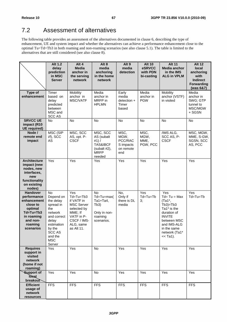
3GPP
3GPP TR 23.856 V10.0.0 (2010-09)67Release 10
7.2 Assessment of alternatives The following table provides an assessment of the alternatives documented in clause 6, describing the type of enhancement, UE and system impact and whether the alternatives can achieve a performance enhancement close to the optimal Tu=Td=Tb3 in both roaming and non-roaming scenarios (see also clause 5.1). The table is limited to the alternatives that are still considered (see also clause 8).
Alt 1.2
delay prediction
in MSC Server
Alt 4 Media
anchor in the serving
network
Alt 8 media
anchoring in the home
network
Alt 9 media
detection
Alt 10 eSRVCC with PDN bi-casting
Alt 11 Media anchor
in the IMS ALG in VPLM
Alt 12 local
anchoring with
Indirect Forwarding (was 6&7)
Type of enhancement
Timer based on delay predicted between MSC and SCC AS
Mobility anchor in MSC/VATF
Media anchor in MRFP in HPLMN
Early media detection + Timer based
Media anchor in PGW
Mobility anchor (VSTF) in visited
Media anchor in SWG; GTP tunnel to MSC/MGW + SGSN
SRVCC UE impact (R10 UE required)
No No No No No No No
Node / remote end
impact
MSC (SIP i/f), SCC AS
MSC, SCC AS, opt. P-CSCF
MSC, SCC AS (subalt #1) / TAS&IBCF (subalt #2), MRFP needed
MSC, MGW, PCC/RACS impacts on remote end
MSC, MGW, MME, PGW, PCC
/IMS ALG, SCC AS, P-CSCF
MSC, MGW, MME, S-GW, SGSN, SCC AS, PCC
Architecture impact (new nodes, new interfaces,
new functionality on existing
nodes)
Yes Yes Yes Yes Yes Yes Yes
Handover performance enhancement
close to optimal
Td=Tu=Tb3 in roaming and non-roaming
scenarios
No Depend on the delay spread in the network and correct delay estimation by the SCC AS and the MSC Server
Yes Td=Tu=Tb3 if VATF in MSC Server selected by MME; If VATF in P-CSCF / IMS-ALG, same as Alt 11.
No Td=Tu=max(Ta1+Ta4, Tb3) Only in non-roaming scenarios.
No, Only if there is DL media
Yes Td=Tu=Tb3;
Yes Td= Tu = Max (Ta1*, Tb3)=Tb3 Ta1* is the duration of INVITE between MSC and IMS-ALG in the same network (Ta1* << Ta1).
Yes Td=Tu=Tb
Requires support in
visited network
(home if not roaming)
Yes Yes No Yes Yes Yes Yes
Support of local
breakout
Yes Yes No Yes Yes Yes Yes
Efficient usage of network
resources
FFS FFS FFS FFS FFS FFS FFS
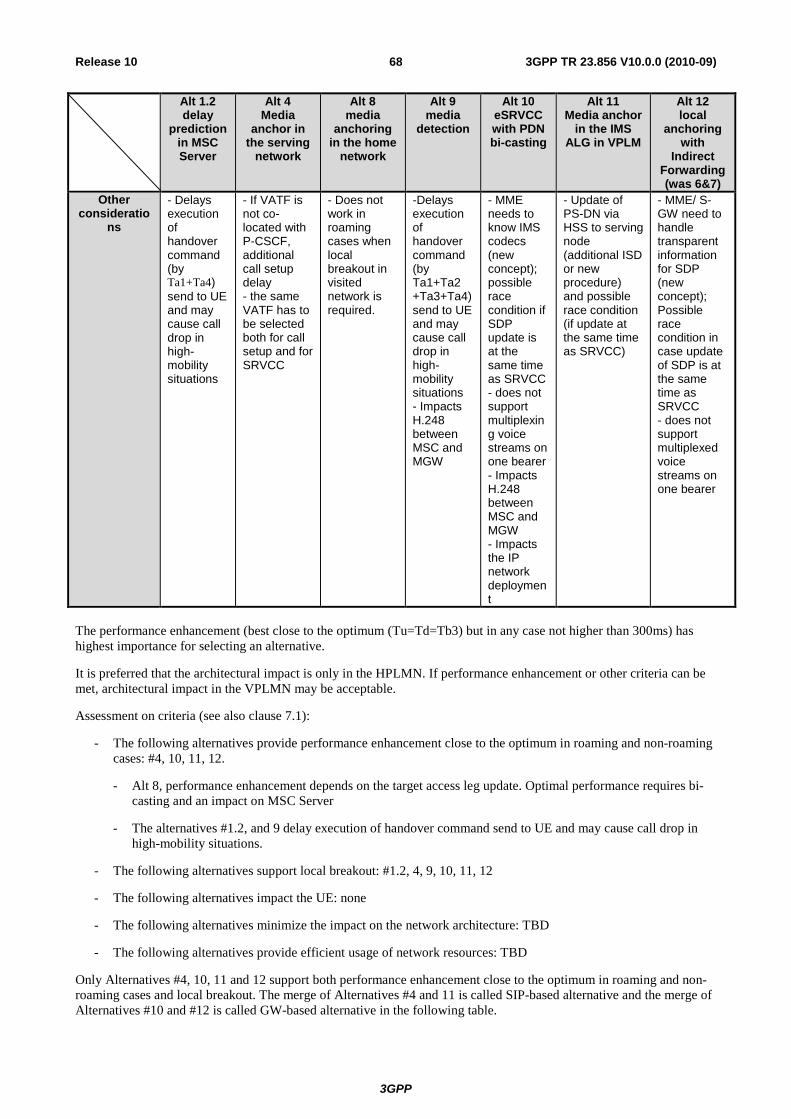
3GPP
3GPP TR 23.856 V10.0.0 (2010-09)68Release 10
Alt 1.2 delay
prediction in MSC Server
Alt 4 Media
anchor in the serving
network
Alt 8 media
anchoring in the home
network
Alt 9 media
detection
Alt 10 eSRVCC with PDN bi-casting
Alt 11 Media anchor
in the IMS ALG in VPLM
Alt 12 local
anchoring with
Indirect Forwarding (was 6&7)
Other consideratio
ns
- Delays execution of handover command (by Ta1+Ta4) send to UE and may cause call drop in high-mobility situations
- If VATF is not co-located with P-CSCF, additional call setup delay - the same VATF has to be selected both for call setup and for SRVCC
- Does not work in roaming cases when local breakout in visited network is required.
-Delays execution of handover command (by Ta1+Ta2 +Ta3+Ta4) send to UE and may cause call drop in high-mobility situations - Impacts H.248 between MSC and MGW
- MME needs to know IMS codecs (new concept); possible race condition if SDP update is at the same time as SRVCC - does not support multiplexing voice streams on one bearer - Impacts H.248 between MSC and MGW - Impacts the IP network deployment
- Update of PS-DN via HSS to serving node (additional ISD or new procedure) and possible race condition (if update at the same time as SRVCC)
- MME/ S-GW need to handle transparent information for SDP (new concept); Possible race condition in case update of SDP is at the same time as SRVCC - does not support multiplexed voice streams on one bearer
The performance enhancement (best close to the optimum (Tu=Td=Tb3) but in any case not higher than 300ms) has highest importance for selecting an alternative.
It is preferred that the architectural impact is only in the HPLMN. If performance enhancement or other criteria can be met, architectural impact in the VPLMN may be acceptable.
Assessment on criteria (see also clause 7.1):
- The following alternatives provide performance enhancement close to the optimum in roaming and non-roaming cases: #4, 10, 11, 12.
- Alt 8, performance enhancement depends on the target access leg update. Optimal performance requires bi-casting and an impact on MSC Server
- The alternatives #1.2, and 9 delay execution of handover command send to UE and may cause call drop in high-mobility situations.
- The following alternatives support local breakout: #1.2, 4, 9, 10, 11, 12
- The following alternatives impact the UE: none
- The following alternatives minimize the impact on the network architecture: TBD
- The following alternatives provide efficient usage of network resources: TBD
Only Alternatives #4, 10, 11 and 12 support both performance enhancement close to the optimum in roaming and non-roaming cases and local breakout. The merge of Alternatives #4 and 11 is called SIP-based alternative and the merge of Alternatives #10 and #12 is called GW-based alternative in the following table.
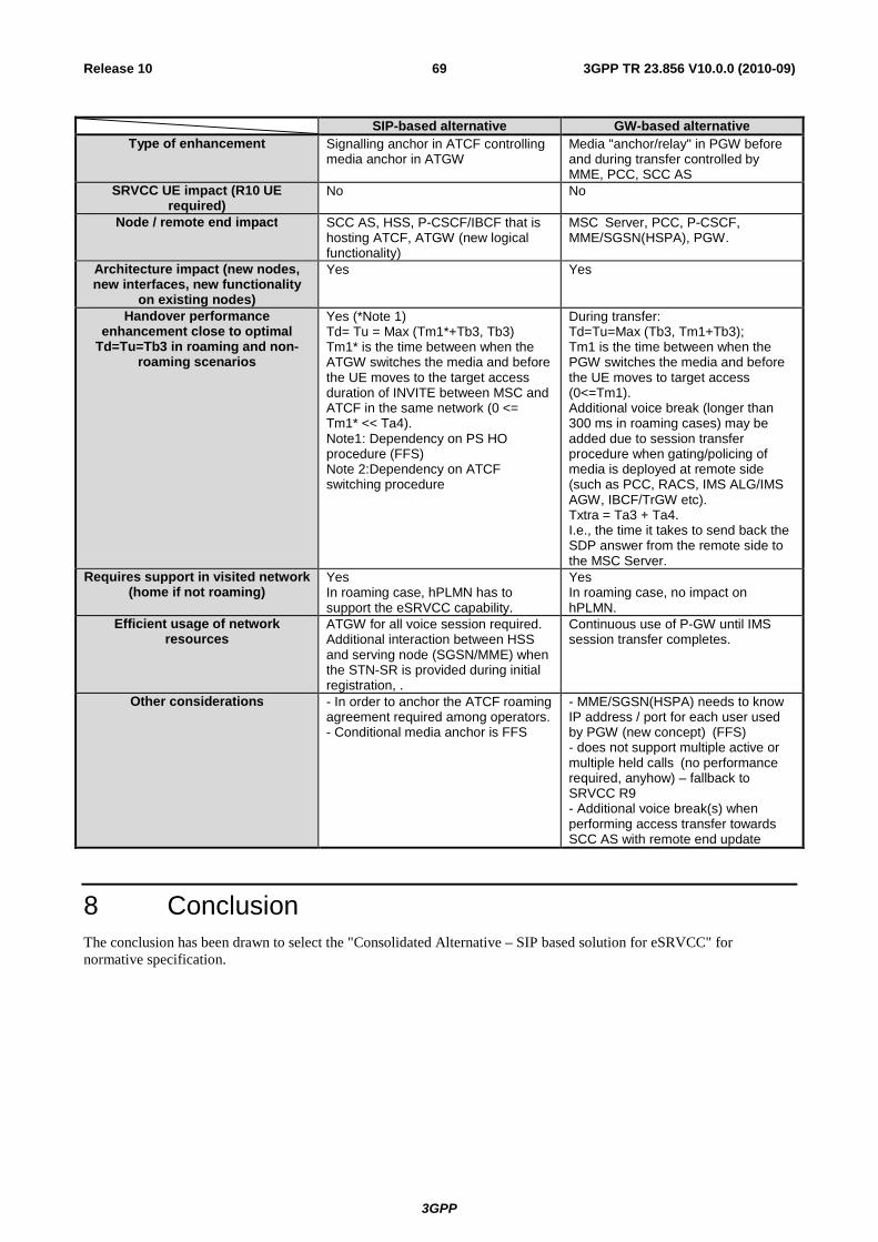
3GPP
3GPP TR 23.856 V10.0.0 (2010-09)69Release 10
SIP-based alternative GW-based alternative
Type of enhancement Signalling anchor in ATCF controlling media anchor in ATGW
Media "anchor/relay" in PGW before and during transfer controlled by MME, PCC, SCC AS
SRVCC UE impact (R10 UE required)
No No
Node / remote end impact SCC AS, HSS, P-CSCF/IBCF that is hosting ATCF, ATGW (new logical functionality)
MSC Server, PCC, P-CSCF, MME/SGSN(HSPA), PGW.
Architecture impact (new nodes, new interfaces, new functionality
on existing nodes)
Yes Yes
Handover performance enhancement close to optimal
Td=Tu=Tb3 in roaming and non-roaming scenarios
Yes (*Note 1) Td= Tu = Max (Tm1*+Tb3, Tb3) Tm1* is the time between when the ATGW switches the media and before the UE moves to the target access duration of INVITE between MSC and ATCF in the same network (0 <= Tm1* << Ta4). Note1: Dependency on PS HO procedure (FFS) Note 2:Dependency on ATCF switching procedure
During transfer: Td=Tu=Max (Tb3, Tm1+Tb3); Tm1 is the time between when the PGW switches the media and before the UE moves to target access (0<=Tm1). Additional voice break (longer than 300 ms in roaming cases) may be added due to session transfer procedure when gating/policing of media is deployed at remote side (such as PCC, RACS, IMS ALG/IMS AGW, IBCF/TrGW etc). Txtra = Ta3 + Ta4. I.e., the time it takes to send back the SDP answer from the remote side to the MSC Server.
Requires support in visited network (home if not roaming)
Yes In roaming case, hPLMN has to support the eSRVCC capability.
Yes In roaming case, no impact on hPLMN.
Efficient usage of network resources
ATGW for all voice session required. Additional interaction between HSS and serving node (SGSN/MME) when the STN-SR is provided during initial registration, .
Continuous use of P-GW until IMS session transfer completes.
Other considerations - In order to anchor the ATCF roaming agreement required among operators. - Conditional media anchor is FFS
- MME/SGSN(HSPA) needs to know IP address / port for each user used by PGW (new concept) (FFS) - does not support multiple active or multiple held calls (no performance required, anyhow) – fallback to SRVCC R9 - Additional voice break(s) when performing access transfer towards SCC AS with remote end update
8 Conclusion The conclusion has been drawn to select the "Consolidated Alternative – SIP based solution for eSRVCC" for normative specification.
3GPP
3GPP TR 23.856 V10.0.0 (2010-09)70Release 10
Annex A: Reducing the call drop probability This annex defines a method of reducing the call drop probability during the SRVCC procedure.
A.1 Pre-handover optimization
A.1.1 Architecture Reference Model The architecture model of Rel-8 SRVCC is not affected.
A.1.2 Functional Entities Editor's Note: This subclause will define the functionalities of functional entities for the enhanced SRVCC.
A.1.2.1 MSC Server Besides the functions defined in TS 23.216 [3], an MSC Server provides the following functions:
- Sending back a pre-Handover Notification to MME after CS handover preparation procedure.
- Invoking an IMS Service Continuity procedure specified in TS 23.216 [3] or enhanced to optimize SRVCC handover in this study report;
- Sending back PS to CS handover response to the source MME as specified in TS 23.216 [3] when the IMS Service Continuity procedure succeeds.
A.1.2.2 MME Besides the functions defined in TS 23.216 [3], an MME shall handle the pre-Handover Notification from MSC Server.
A.1.2.3 E-UTRAN Besides the functions defined in TS 36.413 [9], the source eNB provides the following functions:
- Handling the pre-Handover Command from MME.
- Restarting the timer for the Handover Preparation procedure to wait for the final Handover Command from MME.
A.1.2.4 UE Besides the functions defined in TS 23.216 [3], the UE provides the following functions:
- Handling the pre-Handover Command from E-UTRAN.
- Performing handover procedures without the final Handover Command in some conditions.
A.1.3 Message Flows The Pre-handover optimization is shown in the following figure.
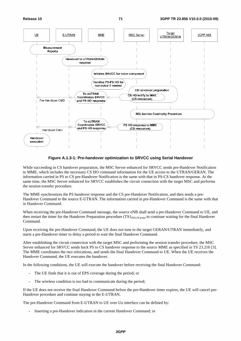
3GPP
3GPP TR 23.856 V10.0.0 (2010-09)71Release 10
Figure A.1.3-1: Pre-handover optimization to SRVCC using Serial Handover
While succeeding in CS handover preparation, the MSC Server enhanced for SRVCC sends pre-Handover Notification to MME, which includes the necessary CS HO command information for the UE access to the UTRAN/GERAN. The information carried in PS to CS pre-Handover Notification is the same with that in PS-CS handover response. At the same time, the MSC Server enhanced for SRVCC establishes the circuit connection with the target MSC and performs the session transfer procedure.
The MME synchronizes the PS handover response and the CS pre-Handover Notification, and then sends a pre-Handover Command to the source E-UTRAN. The information carried in pre-Handover Command is the same with that in Handover Command.
When receiving the pre-Handover Command message, the source eNB shall send a pre-Handover Command to UE, and then restart the timer for the Handover Preparation procedure (TS1RELOCprep) to continue waiting for the final Handover Command.
Upon receiving the pre-Handover Command, the UE does not tune to the target GERAN/UTRAN immediately, and starts a pre-Handover timer to delay a period to wait the final Handover Command.
After establishing the circuit connection with the target MSC and performing the session transfer procedure, the MSC Server enhanced for SRVCC sends back PS to CS handover response to the source MME as specified in TS 23.216 [3]. The MME coordinates the two relocations, and sends the final Handover Command to UE. When the UE receives the Handover Command, the UE executes the handover.
In the following conditions, the UE will execute the handover before receiving the final Handover Command:
- The UE finds that it is out of EPS coverage during the period; or
- The wireless condition is too bad to communicate during the period;
If the UE does not receive the final Handover Command before the pre-Handover timer expires, the UE will cancel pre-Handover procedure and continue staying in the E-UTRAN.
The pre-Handover Command from E-UTRAN to UE over Uu interface can be defined by:
- Inserting a pre-Handover indication in the current Handover Command; or
3GPP
3GPP TR 23.856 V10.0.0 (2010-09)72Release 10
- Defining a new pre-Handover Command message.
NOTE 1: If the pre-Handover Command is defined using a pre-Handover indication in Handover Command, the pre-Rel-10 SRVCC UE will ignore the indication and execute the handover procedure immediately as specified in TS 23.216 [3]. The MSC or the MME may not send the final Handover Command to the E-UTRAN if the MSC or the MME finds that the handover completes. So the backward compatibility to the UE of previous releases is provided. This alternative does not improve the performance of pre-Rel-10 SRVCC UE.
NOTE 2: If the pre-Handover Command is defined using a new message, the pre-Rel-10 SRVCC UE will discard the message. When the final Handover Command arrives, the UE executes the handover. So the backward compatibility to the UE of previous releases is also provided. This alternative can improve the interrupt time performance, but has no contribution to the high mobility.
The approaches defining pre-Hanover Command over Uu interface can be also applied to the definitions of the pre-Handover Notification from MSC to MME over Sv interface and the pre-Handover Command from MME to E-UTRAN over S1 interface.
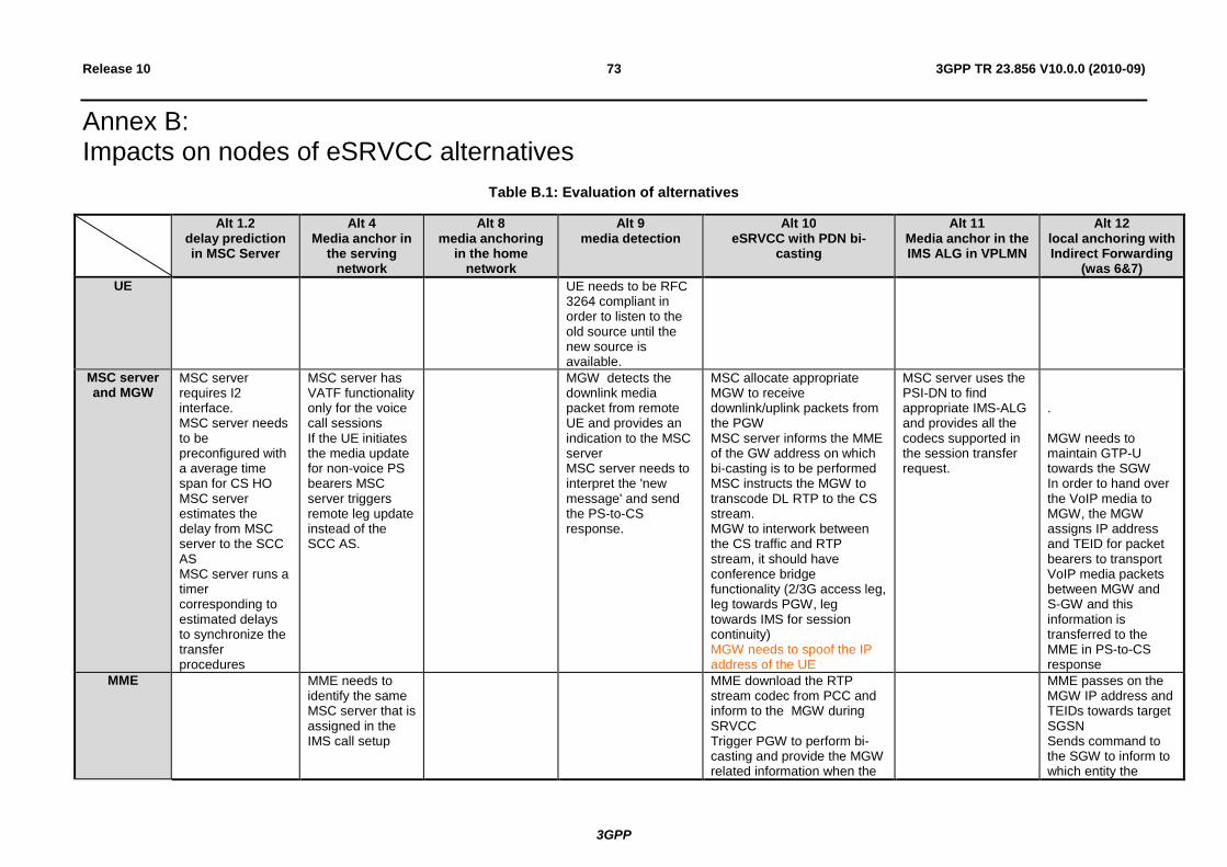
3GPP
3GPP TR 23.856 V10.0.0 (2010-09)73Release 10
Annex B: Impacts on nodes of eSRVCC alternatives
Table B.1: Evaluation of alternatives
Alt 1.2 delay prediction in MSC Server
Alt 4 Media anchor in
the serving network
Alt 8 media anchoring
in the home network
Alt 9 media detection
Alt 10 eSRVCC with PDN bi-
casting
Alt 11 Media anchor in the IMS ALG in VPLMN
Alt 12 local anchoring with Indirect Forwarding
(was 6&7) UE UE needs to be RFC
3264 compliant in order to listen to the old source until the new source is available.
MSC server and MGW
MSC server requires I2 interface. MSC server needs to be preconfigured with a average time span for CS HO MSC server estimates the delay from MSC server to the SCC AS MSC server runs a timer corresponding to estimated delays to synchronize the transfer procedures
MSC server has VATF functionality only for the voice call sessions If the UE initiates the media update for non-voice PS bearers MSC server triggers remote leg update instead of the SCC AS.
MGW detects the downlink media packet from remote UE and provides an indication to the MSC server MSC server needs to interpret the 'new message' and send the PS-to-CS response.
MSC allocate appropriate MGW to receive downlink/uplink packets from the PGW MSC server informs the MME of the GW address on which bi-casting is to be performed MSC instructs the MGW to transcode DL RTP to the CS stream. MGW to interwork between the CS traffic and RTP stream, it should have conference bridge functionality (2/3G access leg, leg towards PGW, leg towards IMS for session continuity) MGW needs to spoof the IP address of the UE
MSC server uses the PSI-DN to find appropriate IMS-ALG and provides all the codecs supported in the session transfer request.
. MGW needs to maintain GTP-U towards the SGW In order to hand over the VoIP media to MGW, the MGW assigns IP address and TEID for packet bearers to transport VoIP media packets between MGW and S-GW and this information is transferred to the MME in PS-to-CS response
MME MME needs to identify the same MSC server that is assigned in the IMS call setup
MME download the RTP stream codec from PCC and inform to the MGW during SRVCC Trigger PGW to perform bi-casting and provide the MGW related information when the
MME passes on the MGW IP address and TEIDs towards target SGSN Sends command to the SGW to inform to which entity the
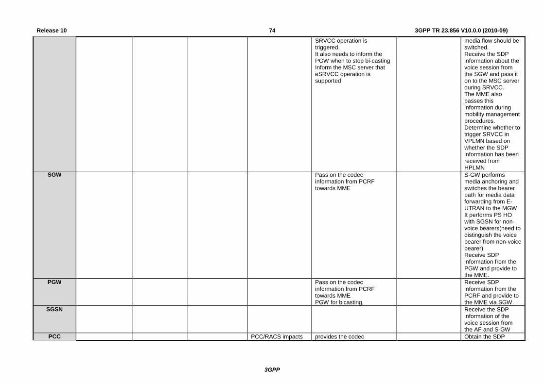
3GPP
3GPP TR 23.856 V10.0.0 (2010-09)74Release 10
SRVCC operation is triggered. It also needs to inform the PGW when to stop bi-casting Inform the MSC server that eSRVCC operation is supported
media flow should be switched. Receive the SDP information about the voice session from the SGW and pass it on to the MSC server during SRVCC. The MME also passes this information during mobility management procedures. Determine whether to trigger SRVCC in VPLMN based on whether the SDP information has been received from HPLMN
SGW Pass on the codec information from PCRF towards MME
S-GW performs media anchoring and switches the bearer path for media data forwarding from E-UTRAN to the MGW It performs PS HO with SGSN for non-voice bearers(need to distinguish the voice bearer from non-voice bearer) Receive SDP information from the PGW and provide to the MME.
PGW Pass on the codec information from PCRF towards MME PGW for bicasting,
Receive SDP information from the PCRF and provide to the MME via SGW.
SGSN Receive the SDP information of the voice session from the AF and S-GW
PCC PCC/RACS impacts provides the codec Obtain the SDP
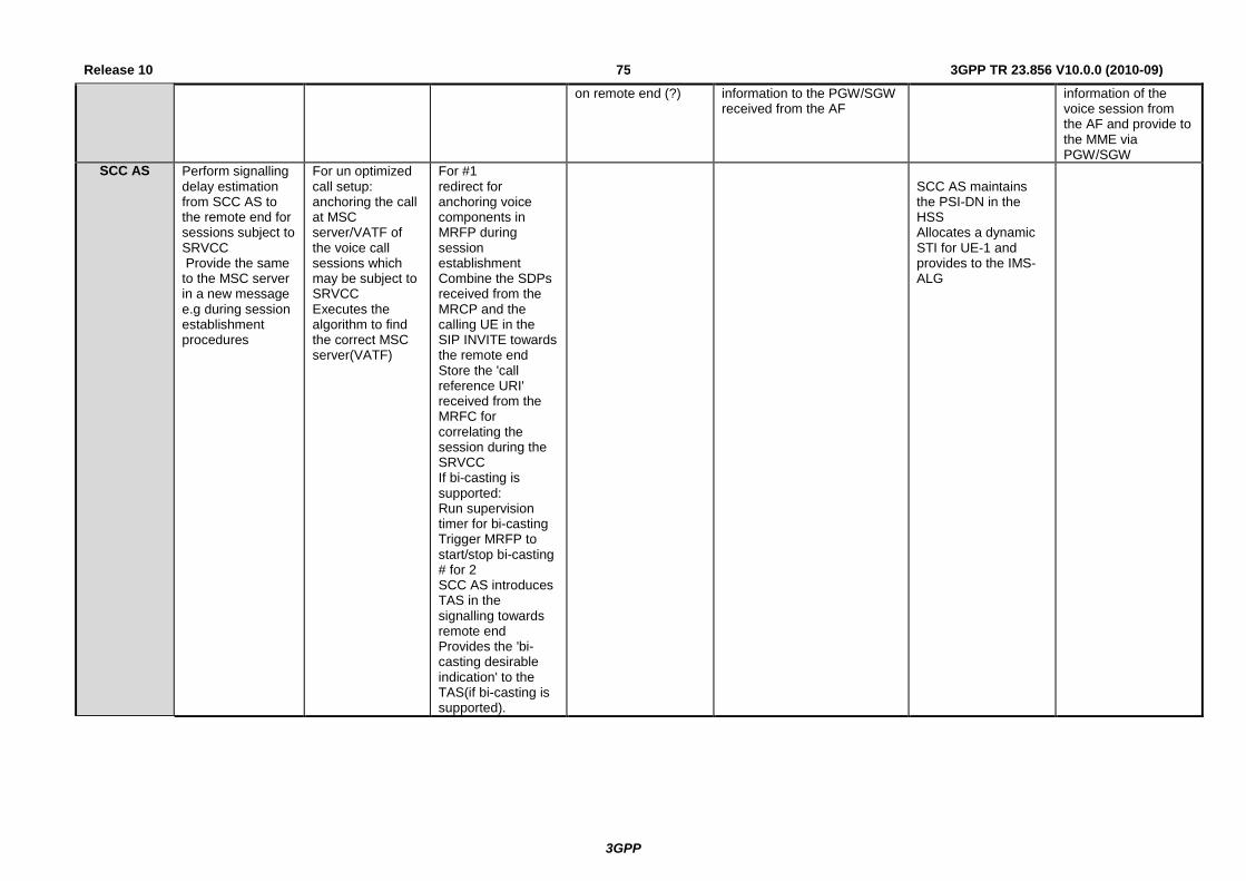
3GPP
3GPP TR 23.856 V10.0.0 (2010-09)75Release 10
on remote end (?)
information to the PGW/SGW received from the AF
information of the voice session from the AF and provide to the MME via PGW/SGW
SCC AS Perform signalling delay estimation from SCC AS to the remote end for sessions subject to SRVCC Provide the same to the MSC server in a new message e.g during session establishment procedures
For un optimized call setup: anchoring the call at MSC server/VATF of the voice call sessions which may be subject to SRVCC Executes the algorithm to find the correct MSC server(VATF)
For #1 redirect for anchoring voice components in MRFP during session establishment Combine the SDPs received from the MRCP and the calling UE in the SIP INVITE towards the remote end Store the 'call reference URI' received from the MRFC for correlating the session during the SRVCC If bi-casting is supported: Run supervision timer for bi-casting Trigger MRFP to start/stop bi-casting # for 2 SCC AS introduces TAS in the signalling towards remote end Provides the 'bi-casting desirable indication' to the TAS(if bi-casting is supported).
SCC AS maintains the PSI-DN in the HSS Allocates a dynamic STI for UE-1 and provides to the IMS-ALG
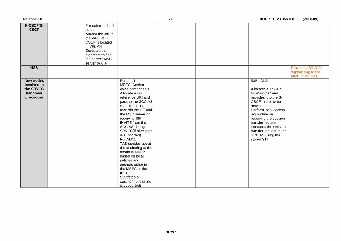
3GPP
3GPP TR 23.856 V10.0.0 (2010-09)76Release 10P-CSCF/S-
CSCF For optimized call
setup: Anchor the call in the VATF if P-CSCF is located in VPLMN Executes the algorithm to find the correct MSC server (VATF)
HSS Provides eSRVCC support flag to the MME in VPLMN
New nodes involved in the SRVCC handover procedure
For alt #1: MRFC: Anchor voice components , Allocate a call reference URI and pass to the SCC AS Start bi-casting towards the UE and the MSC server on receiving SIP INVITE from the SCC AS during SRVCC(if bi-casting is supported). For Alt#2: TAS decides about the anchoring of the media in MRFP based on local policies and anchors either in the MRFC or the IBCF. Start/stop bi-casting(if bi-casting is supported)
IMS –ALG: Allocates a PSI-DN for eSRVCC and provides it to the S-CSCF in the home network Perform local access leg update on receiving the session transfer request Forwards the session transfer request to the SCC AS using the stored STI

3GPP
3GPP TR 23.856 V10.0.0 (2010-09)77Release 10
Annex C: Examples of ATCF/ATGW collocation – SIP based solution for eSRVCC
C.1 General This Annex illustrates a number of collocation options of the ATCF/ATGW and the implications it will have. In particular, this is intended to be used as a guidance of what existing protocols that can be used to control the media anchoring, and to show how these can be reused without further extensions. These are only examples, and should not be viewed as an exhaustive list.
C.2 IMS ALG/IMS AGW The following alternative shows the collocation of the ATCF with the IMS ALG of the P-CSCF, and the ATGW with the IMS AGW.
Iq
PCSCF
IMS AGW(ATGW)
Gm Mw
MSC
MGW
IMS ALG /ATCF
Logical entity of control plane
Logical entity of user plane
NAT
Mw/I2
Figure C.2-1: Collocation with IMS ALG/IMS AGW
In this alternative, the interface between P-CSCF and IMS AGW will be the Iq reference point. The Iq reference point already supports the necessary procedures of anchoring a session (see TS 23.334 [13]). In this alternative, the ATCF is included in signalling path during registration when the UE sends the Register to the P-CSCF. It is considered to be internal logic in the P-CSCF that includes the ATCF.
A variant of the above collocation would be to also have the media anchoring part in the PGW. Also in this case, the existing standard interface Iq can be used as is without any extensions.
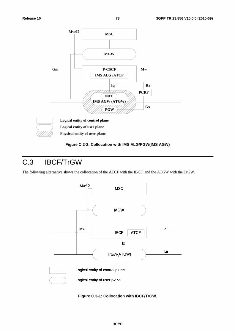
3GPP
3GPP TR 23.856 V10.0.0 (2010-09)78Release 10
Iq
PCSCFGm Mw
MSC
MGW
IMS ALG /ATCF
PGW
IMS AGW (ATGW)NAT
Logical entity of control plane
Logical entity of user plane
Physical entity of user plane
Mw/I2
PCRF
Rx
Gx
Figure C.2-2: Collocation with IMS ALG/PGW(IMS AGW)
C.3 IBCF/TrGW The following alternative shows the collocation of the ATCF with the IBCF, and the ATGW with the TrGW.
Figure C.3-1: Collocation with IBCF/TrGW.
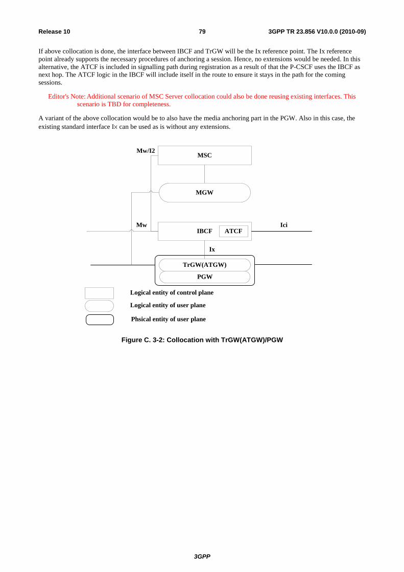
3GPP
3GPP TR 23.856 V10.0.0 (2010-09)79Release 10
If above collocation is done, the interface between IBCF and TrGW will be the Ix reference point. The Ix reference point already supports the necessary procedures of anchoring a session. Hence, no extensions would be needed. In this alternative, the ATCF is included in signalling path during registration as a result of that the P-CSCF uses the IBCF as next hop. The ATCF logic in the IBCF will include itself in the route to ensure it stays in the path for the coming sessions.
Editor's Note: Additional scenario of MSC Server collocation could also be done reusing existing interfaces. This scenario is TBD for completeness.
A variant of the above collocation would be to also have the media anchoring part in the PGW. Also in this case, the existing standard interface Ix can be used as is without any extensions.
Ix
IBCF
TrGW(ATGW)
IciMw
MSC
MGW
ATCF
Logical entity of control plane
Logical entity of user plane
Mw/I2
PGW
Phsical entity of user plane
Figure C. 3-2: Collocation with TrGW(ATGW)/PGW

3GPP
3GPP TR 23.856 V10.0.0 (2010-09)80Release 10
Annex D: Change history
Change history Date TSG # TSG Doc. CR Rev Subject/Comment Old New 2010-09 SP-49 SP-100563 - - MCC Editorial update for presentation to TSG SA for Approval 2.0.1 2.1.0 2010-09 SP-49 - - - MCC Update to version 10.0.0 after TSG SA Approval 2.1.0 10.0.0


![[Poster Presentation] Reinforcement Learning Aided ......THE INSTITUTE OF ELECTRONICS, IEICE Technical Report INFORMATION AND COMMUNICATION ENGINEERS This article is a technical report](https://img.pdfslide.tips/doc/110x75/5f7bc1e90863ca188f169355/poster-presentation-reinforcement-learning-aided-the-institute-of-electronics.jpg)