Embed Size (px)
Citation preview
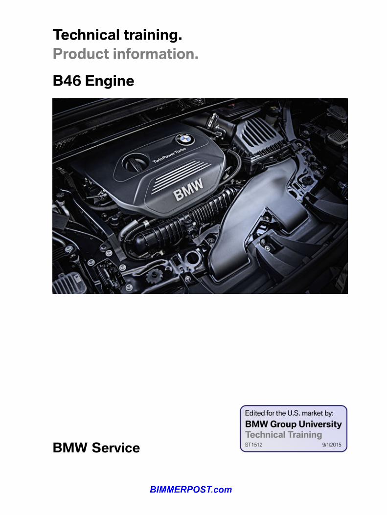
Technical�training.Product�information.
BMW�Service
B46�Engine
General�informationSymbols�used
The�following�symbol�is�used�in�this�document�to�facilitate�better�comprehension�or�to�draw�attentionto�very�important�information:
Contains�important�safety�information�and�information�that�needs�to�be�observed�strictly�in�order�toguarantee�the�smooth�operation�of�the�system.
Information�status�and�national-market�versions
BMW�Group�vehicles�meet�the�requirements�of�the�highest�safety�and�quality�standards.�Changesin�requirements�for�environmental�protection,�customer�benefits�and�design�render�necessarycontinuous�development�of�systems�and�components.�Consequently,�there�may�be�discrepanciesbetween�the�contents�of�this�document�and�the�vehicles�available�in�the�training�course.
This�document�basically�relates�to�the�European�version�of�left-hand�drive�vehicles.�Some�operatingelements�or�components�are�arranged�differently�in�right-hand�drive�vehicles�than�shown�in�thegraphics�in�this�document.�Further�differences�may�arise�as�a�result�of�the�equipment�specification�inspecific�markets�or�countries.
Additional�sources�of�information
Further�information�on�the�individual�topics�can�be�found�in�the�following:
• Owner's�Handbook• Integrated�Service�Technical�Application.
Contact:�[email protected]
©2014�BMW�AG,�Munich
Reprints�of�this�publication�or�its�parts�require�the�written�approval�of�BMW�AG,�Munich
The�information�contained�in�this�document�forms�an�integral�part�of�the�technical�training�of�theBMW�Group�and�is�intended�for�the�trainer�and�participants�in�the�seminar.�Refer�to�the�latest�relevantinformation�systems�of�the�BMW�Group�for�any�changes/additions�to�the�technical�data.
Contact:Sebastian�RiedelTel.:�+49�(0)�89�382�65044E-mail:�[email protected]
Information�status:�June�2014BV-72/Technical�Training
B46�EngineContents1. Introduction.............................................................................................................................................................................................................................................1
1.1. Engine�designation............................................................................................................................................................................................. 11.2. Engine�identification......................................................................................................................................................................................... 2
1.2.1. 4-cylinder�engine..................................................................................................................................................................21.3. Highlights............................................................................................................................................................................................................................3
1.3.1. Installation�positions........................................................................................................................................................31.3.2. Advantages.....................................................................................................................................................................................41.3.3. Overview�of�technical�features........................................................................................................................4
1.4. Modular�design..........................................................................................................................................................................................................51.4.1. TwinPower�Turbo..................................................................................................................................................................7
1.5. Technical�data............................................................................................................................................................................................................. 71.5.1. Model�overview........................................................................................................................................................................8
1.6. Engine�acoustics.................................................................................................................................................................................................... 81.6.1. Comparison....................................................................................................................................................................................91.6.2. Active�Sound�Design................................................................................................................................................. 12
2. Engine�Mechanical................................................................................................................................................................................................................142.1. Engine�housing.....................................................................................................................................................................................................14
2.1.1. Cylinder�head�cover.....................................................................................................................................................152.1.2. Cylinder�head.........................................................................................................................................................................222.1.3. Crankcase.....................................................................................................................................................................................242.1.4. Oil�sump......................................................................................................................................................................................... 28
2.2. Crankshaft�drive...................................................................................................................................................................................................332.2.1. Crankshaft....................................................................................................................................................................................332.2.2. Connecting�rod....................................................................................................................................................................402.2.3. Piston...................................................................................................................................................................................................432.2.4. Counterbalance�shafts.............................................................................................................................................452.2.5. Counterbalance�shaft�of�B46�engine............................................................................................... 522.2.6. Torsional�vibration�damper................................................................................................................................552.2.7. Chain�drive..................................................................................................................................................................................57
2.3. Valve�gear.......................................................................................................................................................................................................................602.3.1. Variants.............................................................................................................................................................................................602.3.2. VANOS..............................................................................................................................................................................................612.3.3. Valvetronic................................................................................................................................................................................... 67
2.4. Belt�drive......................................................................................................................................................................................................................... 74
3. Oil�Supply...............................................................................................................................................................................................................................................753.1. Oil�circuit......................................................................................................................................................................................................................... 753.2. Map�control.................................................................................................................................................................................................................773.3. Oil�pump.......................................................................................................................................................................................................................... 78
3.3.1. Map�control�valve.............................................................................................................................................................81
B46�EngineContents
3.3.2. Normal�operation..............................................................................................................................................................823.3.3. Emergency�operation................................................................................................................................................83
3.4. Suction�pipe...............................................................................................................................................................................................................843.5. Pressure-limiting�valve..............................................................................................................................................................................853.6. Oil�filter�module....................................................................................................................................................................................................86
3.6.1. Filter�bypass�valve..........................................................................................................................................................883.6.2. Heat�exchanger�bypass�valve.......................................................................................................................88
4. Cooling�System...........................................................................................................................................................................................................................894.1. Cooling�circuit,�B46�engine...............................................................................................................................................................89
4.1.1. Special�features..................................................................................................................................................................904.2. System�overview,�vehicle......................................................................................................................................................................914.3. Cooling�module.................................................................................................................................................................................................... 924.4. Coolant�pump..........................................................................................................................................................................................................934.5. Expansion�tank......................................................................................................................................................................................................944.6. Coolant...............................................................................................................................................................................................................................95
5. Intake�Air�and�Exhaust�System.....................................................................................................................................................................965.1. Intake�air�system.................................................................................................................................................................................................97
5.1.1. Intake�silencer....................................................................................................................................................................... 985.1.2. Charge�air�cooling...........................................................................................................................................................99
5.2. Exhaust�emission�system.....................................................................................................................................................................995.2.1. Exhaust�turbocharger................................................................................................................................................995.2.2. Blow-off�valve....................................................................................................................................................................1005.2.3. Charging�pressure�control.............................................................................................................................1005.2.4. Exhaust�system�............................................................................................................................................................ 104
6. Vacuum�Supply.......................................................................................................................................................................................................................1096.1. System�overview............................................................................................................................................................................................ 1096.2. Vacuum�pump.....................................................................................................................................................................................................110
7. Fuel�System...................................................................................................................................................................................................................................1127.1. Fuel�pump�control�module.............................................................................................................................................................1137.2. Electric�fuel�pump........................................................................................................................................................................................1137.3. Fuel�preparation...............................................................................................................................................................................................115
7.3.1. Fuel�high-pressure�pump...............................................................................................................................1167.3.2. Direct�rail................................................................................................................................................................................... 1197.3.3. Solenoid�valve�injector........................................................................................................................................ 121
8. Engine�Electrical�System.....................................................................................................................................................................................1298.1. Digital�Motor�Electronics�(DME)............................................................................................................................................129
B46�EngineContents
8.2. System�wiring�diagram,�B46�engine...............................................................................................................................1308.3. Map�ignition........................................................................................................................................................................................................... 132
8.3.1. Diagnostic�functions...............................................................................................................................................1338.3.2. Ignition�coils.........................................................................................................................................................................1358.3.3. Spark�plugs...........................................................................................................................................................................138
8.4. System�overview�for�engine�electrical�system................................................................................................1388.4.1. Transmission�side.......................................................................................................................................................1398.4.2. Side�view...................................................................................................................................................................................1408.4.3. Belt�side......................................................................................................................................................................................141

B46�Engine1.�Introduction
1
This�document�describes�the�special�features�of�the�new�4-cylinder�engine�and�serves�to�supportthe�technical�service.�Due�to�the�huge�similarities,�between�the�B38�Top�engine�and�B46,�the�twoengines�are�described�in�this�one�document.�Some�images�shown�relate�to�the�3-cylinder�engine.The�differences�compared�to�the�4-cylinder�engine�are�shown�and�described�separately.�However,�thesimilarities�are�not�repeated.�The�engines�are�distinguished�as�follows�in�this�document:
• B38�=�3-cylinder�engine• B46�=�4-cylinder�engine• Bx8�=�3�and�4-cylinder�engine
1.1.�Engine�designationIn�the�technical�documentation,�the�engine�designation�is�used�to�ensure�unambiguous�identificationof�the�engine.�Frequently,�only�a�short�designation�is�used,�which�is�explained�in�the�following�table.
Position Meaning Index Explanation1 Engine�developer B BMW�Group�engine2 Engine�type 3
43-cylinder�in-line�engine4-cylinder�in-line�engine
3 Change�to�the�basicengine�concept
68
SULEV/Turbo-Valvetronic�Direct�Injection�(TVDI)Turbo-Valvetronic�Direct�Injection�(TVDI)
4 Working�method�or�fueland�installation�position
A Gasoline�engine,�transversal�installation
5�+�6 Displacement�in1/10 liter
1520
1.5 liter�displacement2.0�liter�displacement
7 Performance�classes KUMOTS
LowestLowerMiddleUpperTopSuper
8 Revision�relevant�toapproval
012
New�developmentFirst�revisionSecond�revision
B46�Engine1.�Introduction
2
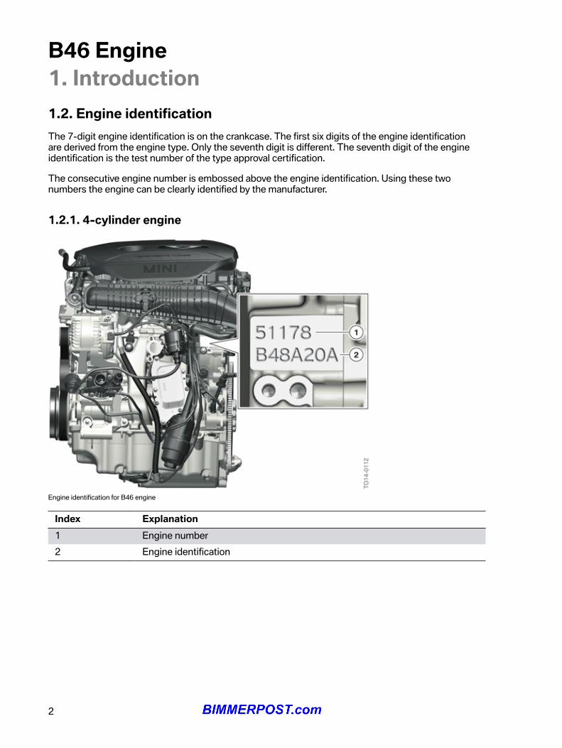
1.2.�Engine�identificationThe�7-digit�engine�identification�is�on�the�crankcase.�The�first�six�digits�of�the�engine�identificationare�derived�from�the�engine�type.�Only�the�seventh�digit�is�different.�The�seventh�digit�of�the�engineidentification�is�the�test�number�of�the�type�approval�certification.
The�consecutive�engine�number�is�embossed�above�the�engine�identification.�Using�these�twonumbers�the�engine�can�be�clearly�identified�by�the�manufacturer.
1.2.1.�4-cylinder�engine
Engine�identification�for�B46�engine
Index Explanation1 Engine�number2 Engine�identification
B46�Engine1.�Introduction
3
1.3.�Highlights
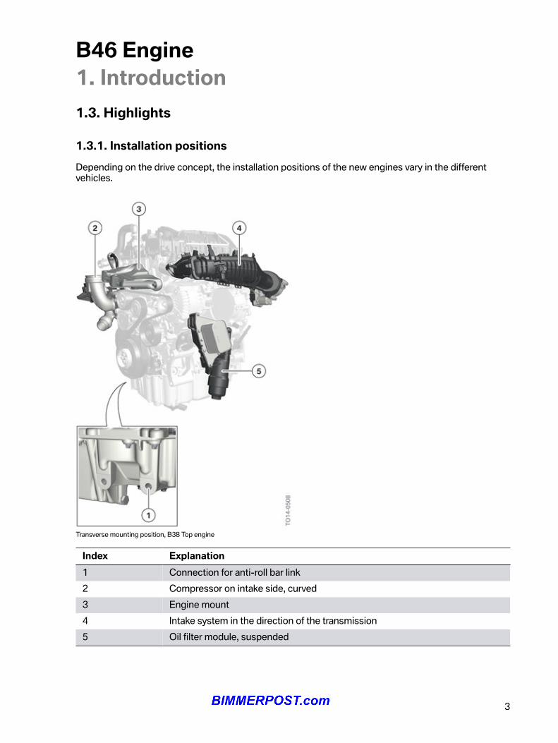
1.3.1.�Installation�positionsDepending�on�the�drive�concept,�the�installation�positions�of�the�new�engines�vary�in�the�differentvehicles.
Transverse�mounting�position,�B38�Top�engine
Index Explanation1 Connection�for�anti-roll�bar�link2 Compressor�on�intake�side,�curved3 Engine�mount4 Intake�system�in�the�direction�of�the�transmission5 Oil�filter�module,�suspended
B46�Engine1.�Introduction
4
This�following�drive�and�installation�variants�are�available:
• Transverse�mountingFront-wheel�drivesFour-wheel�drives
• Automatic�transmission
1.3.2.�Advantages
Benefits�due�to�lower�number�of�cylinders:
• less�weight• fewer�moving�masses• less�spatial�requirement• reduction�of�internal�engine�friction
The�B46�engine�is�based�on�the�familiar�N20�engine.�The�familiar�TVDI1�technology�is�used�in�all�newengines.�An�offset�or�axial�offset,�as�used�in�the�N20�engine,�is�not�used�with�the�new�B46�engine.
The�new�engine�generation�is�mainly�characterized�by�lower�fuel�consumption�and�fewer�exhaustemissions�(ULEV�II).�To�achieve�low�fuel�consumption,�a�map-controlled�oil�pump,�characteristic�mapthermostat�and�injection�system�with�direct-rail�and�electric�arc�wire-sprayed�cylinder�barrels,�amongothers,�are�used.�All�engines�also�receive�an�automatic�engine�start-stop�function�and�intelligentalternator�control�as�a�further�EfficientDynamics�measure.
1TVDI�technology�consists�of:
• T�=�Turbocharger• V�=�Valvetronic• DI�=�Direct-Injection�(direct�fuel�injection)
1.3.3.�Overview�of�technical�featuresB46A20
Map-controlled�oil�pump YesElectric�arc�wire-sprayed�cylinder�barrels YesTwin-scroll�exhaust�turbocharger YesElectrically�adjustable�wastegate�valve YesDirect�rail YesDouble�VANOS YesValvetronic Yes
B46�Engine1.�Introduction
5
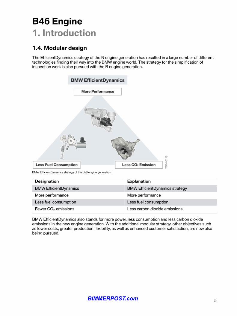
1.4.�Modular�designThe�EfficientDynamics�strategy�of�the�N�engine�generation�has�resulted�in�a�large�number�of�differenttechnologies�finding�their�way�into�the�BMW�engine�world.�The�strategy�for�the�simplification�ofinspection�work�is�also�pursued�with�the�B�engine�generation.
BMW�EfficientDynamics�strategy�of�the�Bx8�engine�generation
Designation ExplanationBMW�EfficientDynamics BMW�EfficientDynamics�strategyMore�performance More�performanceLess�fuel�consumption Less�fuel�consumptionFewer�CO2�emissions Less�carbon�dioxide�emissions
BMW�EfficientDynamics�also�stands�for�more�power,�less�consumption�and�less�carbon�dioxideemissions�in�the�new�engine�generation.�With�the�additional�modular�strategy,�other�objectives�suchas�lower�costs,�greater�production�flexibility,�as�well�as�enhanced�customer�satisfaction,�are�now�alsobeing�pursued.
B46�Engine1.�Introduction
6
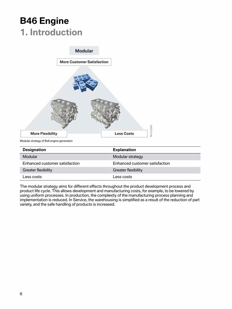
Modular�strategy�of�Bx8�engine�generation
Designation ExplanationModular Modular�strategyEnhanced�customer�satisfaction Enhanced�customer�satisfactionGreater�flexibility Greater�flexibilityLess�costs Less�costs
The�modular�strategy�aims�for�different�effects�throughout�the�product�development�process�andproduct�life�cycle.�This�allows�development�and�manufacturing�costs,�for�example,�to�be�lowered�byusing�uniform�processes.�In�production,�the�complexity�of�the�manufacturing�process�planning�andimplementation�is�reduced.�In�Service,�the�warehousing�is�simplified�as�a�result�of�the�reduction�of�partvariety,�and�the�safe�handling�of�products�is�increased.
B46�Engine1.�Introduction
7
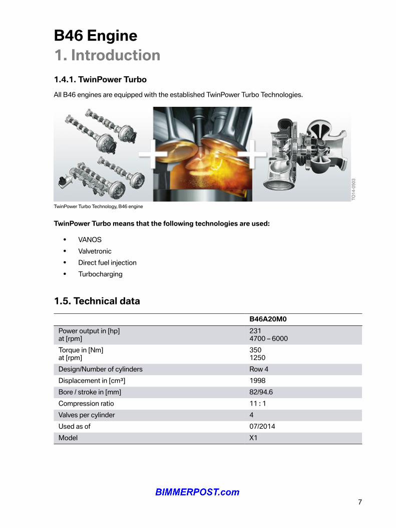
1.4.1.�TwinPower�TurboAll�B46�engines�are�equipped�with�the�established�TwinPower�Turbo�Technologies.
TwinPower�Turbo�Technology,�B46�engine
TwinPower�Turbo�means�that�the�following�technologies�are�used:
• VANOS• Valvetronic• Direct�fuel�injection• Turbocharging
1.5.�Technical�dataB46A20M0
Power�output�in�[hp]at�[rpm]
2314700�–�6000
Torque�in�[Nm]at�[rpm]
3501250
Design/Number�of�cylinders Row�4Displacement�in�[cm³] 1998Bore�/�stroke�in�[mm] 82/94.6Compression�ratio 11�:�1Valves�per�cylinder 4Used�as�of 07/2014Model X1
B46�Engine1.�Introduction
8
1.5.1.�Model�overviewThe�table�below�provides�an�overview�of�the�BMW�models�in�which�the�new�engines�are�used:
BMW�models EngineX1 B46A20M0
1.6.�Engine�acousticsIn�order�to�understand�the�origin�of�the�acoustic�differences,�we�must�take�a�look�at�the�enginemechanics�and�compare�the�design�features�of�the�engine.�The�following�graphics�illustrate�the�originof�the�different�acoustics.
B46�Engine1.�Introduction
9
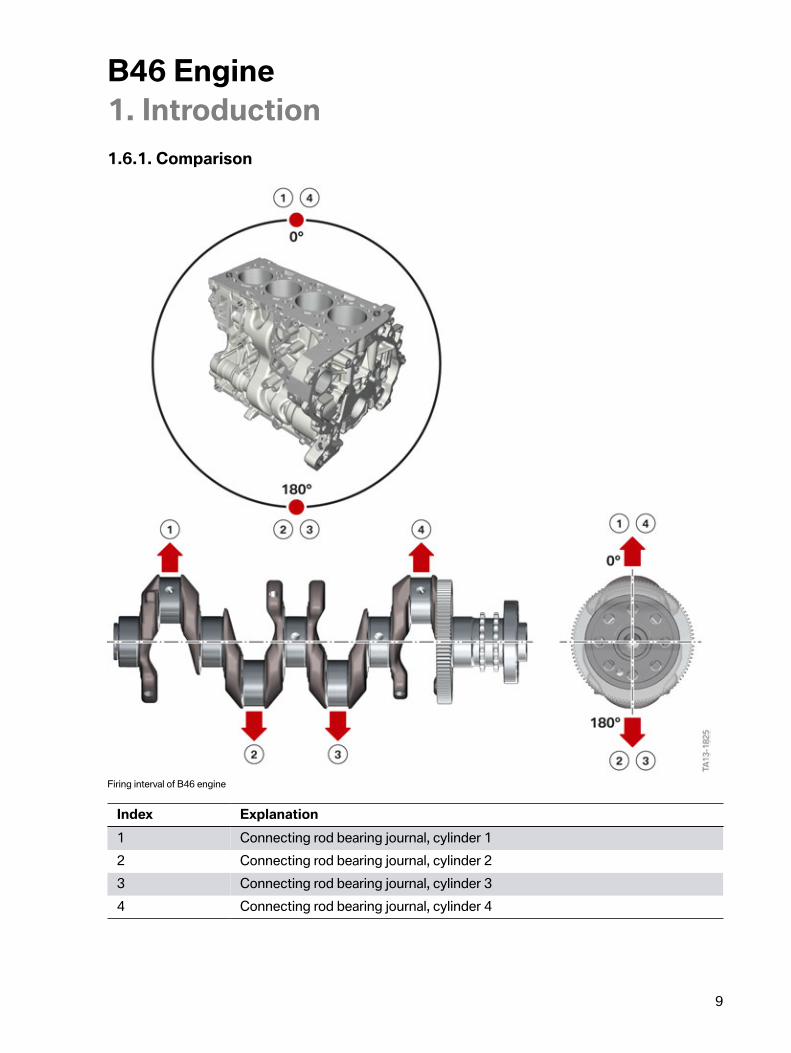
1.6.1.�Comparison
Firing�interval�of�B46�engine
Index Explanation1 Connecting�rod�bearing�journal,�cylinder�12 Connecting�rod�bearing�journal,�cylinder�23 Connecting�rod�bearing�journal,�cylinder�34 Connecting�rod�bearing�journal,�cylinder�4
B46�Engine1.�Introduction
10
The�graphic�shows�a�4-cylinder�in-line�engine�with�a�firing�interval�of�180°�and�a�firing�order�of�1–3–4–2.�One�crankshaft�revolution�(360°)�results�in�two�work�cycles�for�the�4-cylinder�in-line�engine.
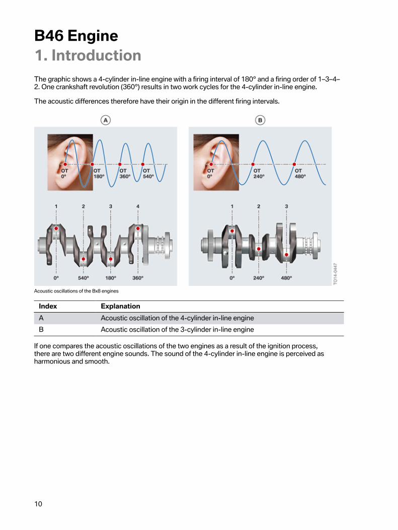
The�acoustic�differences�therefore�have�their�origin�in�the�different�firing�intervals.
Acoustic�oscillations�of�the�Bx8�engines
Index ExplanationA Acoustic�oscillation�of�the�4-cylinder�in-line�engineB Acoustic�oscillation�of�the�3-cylinder�in-line�engine
If�one�compares�the�acoustic�oscillations�of�the�two�engines�as�a�result�of�the�ignition�process,there�are�two�different�engine�sounds.�The�sound�of�the�4-cylinder�in-line�engine�is�perceived�asharmonious�and�smooth.
B46�Engine1.�Introduction
11
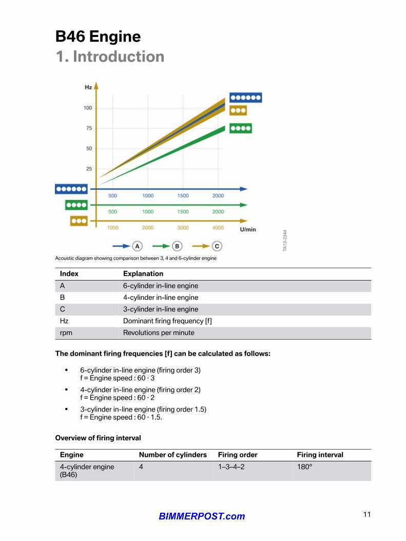
Acoustic�diagram�showing�comparison�between�3,�4�and�6-cylinder�engine
Index ExplanationA 6-cylinder�in-line�engineB 4-cylinder�in-line�engineC 3-cylinder�in-line�engineHz Dominant�firing�frequency�[f]rpm Revolutions�per�minute
The�dominant�firing�frequencies�[f]�can�be�calculated�as�follows:
• 6-cylinder�in-line�engine�(firing�order�3)f�=�Engine�speed�:�60�∙�3
• 4-cylinder�in-line�engine�(firing�order�2)f�=�Engine�speed�:�60�∙�2
• 3-cylinder�in-line�engine�(firing�order�1.5)f�=�Engine�speed�:�60�∙�1.5.
Overview�of�firing�interval
Engine Number�of�cylinders Firing�order Firing�interval4-cylinder�engine(B46)
4 1–3–4–2 180°
B46�Engine1.�Introduction
12
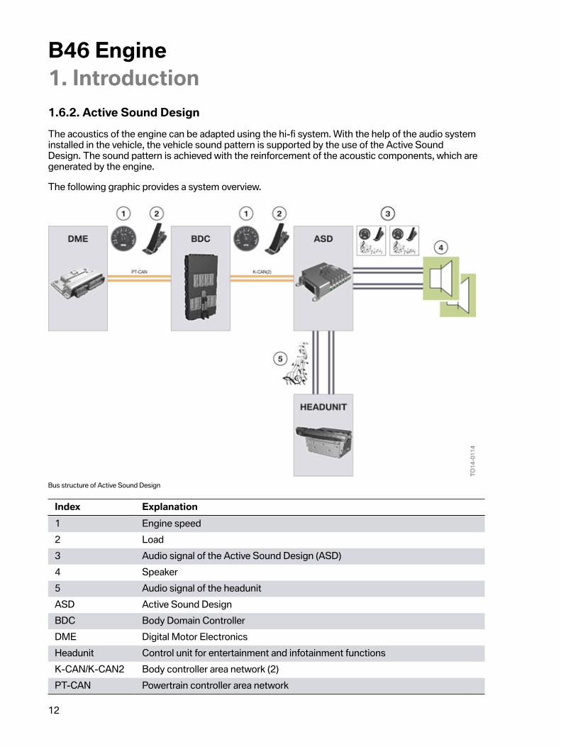
1.6.2.�Active�Sound�DesignThe�acoustics�of�the�engine�can�be�adapted�using�the�hi-fi�system.�With�the�help�of�the�audio�systeminstalled�in�the�vehicle,�the�vehicle�sound�pattern�is�supported�by�the�use�of�the�Active�SoundDesign.�The�sound�pattern�is�achieved�with�the�reinforcement�of�the�acoustic�components,�which�aregenerated�by�the�engine.
The�following�graphic�provides�a�system�overview.
Bus�structure�of�Active�Sound�Design
Index Explanation1 Engine�speed2 Load3 Audio�signal�of�the�Active�Sound�Design�(ASD)4 Speaker5 Audio�signal�of�the�headunitASD Active�Sound�DesignBDC Body�Domain�ControllerDME Digital�Motor�ElectronicsHeadunit Control�unit�for�entertainment�and�infotainment�functionsK-CAN/K-CAN2 Body�controller�area�network�(2)PT-CAN Powertrain�controller�area�network
B46�Engine1.�Introduction
13
The�Digital�Motor�Electronics�(DME)�engine�control�unit�sends�information�about�the�engine�speedand�load�via�the�PT-CAN�to�the�Body�Domain�Controller�(BDC).�The�Body�Domain�Controller�(BDC)transmits�this�information�from�the�PT-CAN�to�the�K-CAN/K-CAN2.�Via�the�K-CAN/K–CAN2�theinformation�reaches�the�Active�Sound�Design�(ASD)�control�unit.�The�Active�Sound�Design�(ASD)control�unit�generates�an�audio�signal�with�this�information.�This�audio�signal�is�modulated�to�the�audiosignal�of�the�headunit�and�forwarded�to�the�loudspeakers.�An�engine�sound�corresponding�to�thedriving�condition�is�output�to�the�driver�via�the�speaker.
The�Active�Sound�Design�(ASD)�can�be�muted�up�to�the�next�terminal�change�via�the�ISTA�diagnosissystem.�It�is�not�possible�to�deactivate�the�Active�Sound�Design�permanently.
B46�Engine2.�Engine�Mechanical
14
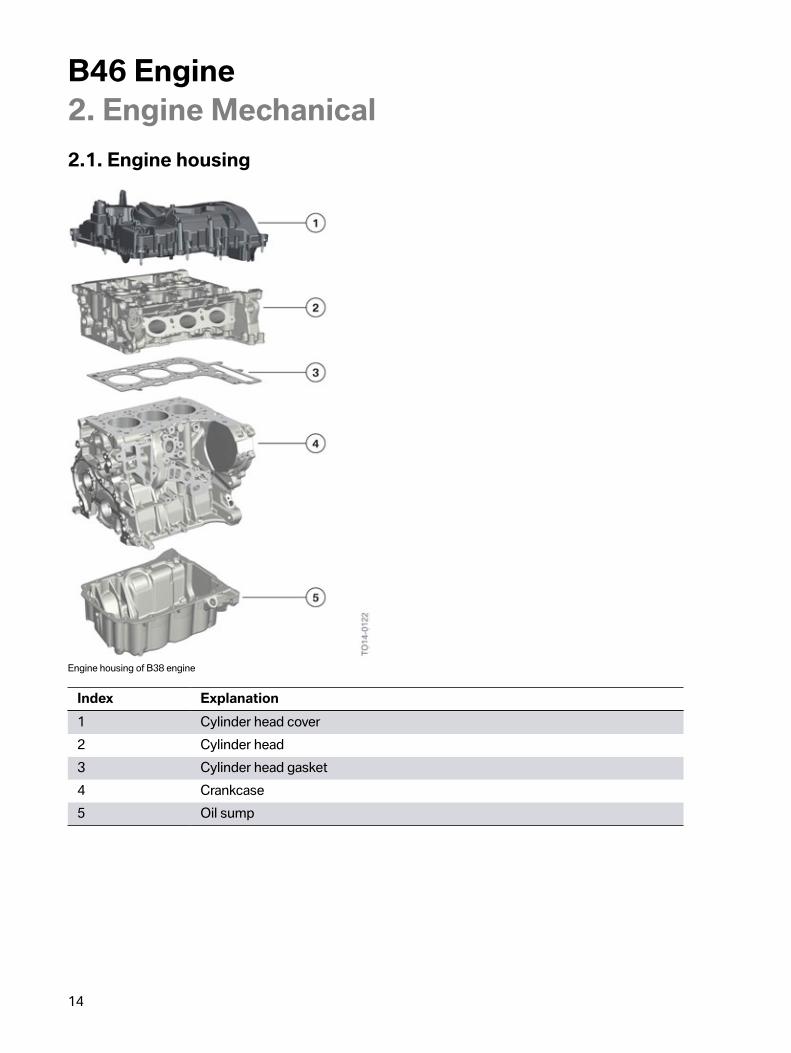
2.1.�Engine�housing
Engine�housing�of�B38�engine
Index Explanation1 Cylinder�head�cover2 Cylinder�head3 Cylinder�head�gasket4 Crankcase5 Oil�sump
B46�Engine2.�Engine�Mechanical
15
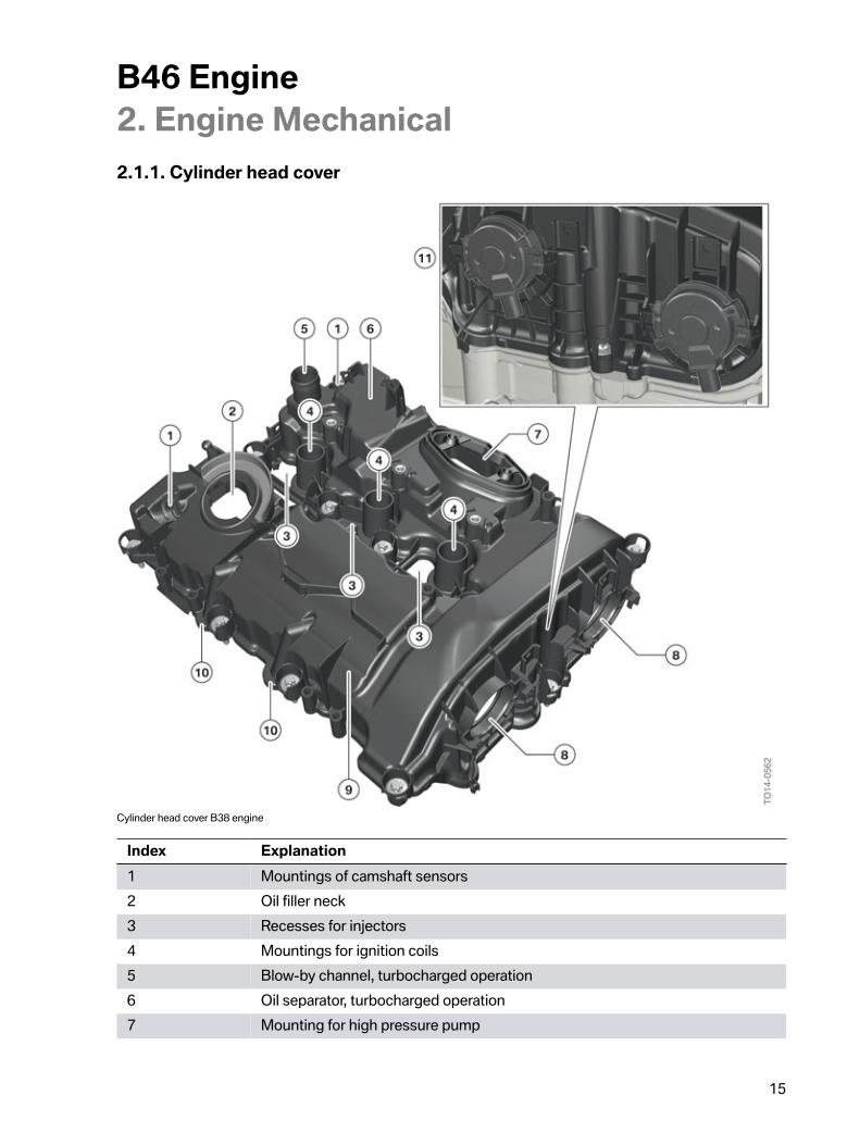
2.1.1.�Cylinder�head�cover
Cylinder�head�cover�B38�engine
Index Explanation1 Mountings�of�camshaft�sensors2 Oil�filler�neck3 Recesses�for�injectors4 Mountings�for�ignition�coils5 Blow-by�channel,�turbocharged�operation6 Oil�separator,�turbocharged�operation7 Mounting�for�high�pressure�pump
B46�Engine2.�Engine�Mechanical
16
Index Explanation8 Mountings�of�VANOS�solenoid�valve�actuators9 Oil�separator,�naturally�aspirated�engine�operation10 Blow-by�channel,�naturally�aspirated�engine�operation11 Bayonet�fitting�with�retaining�clips
As�is�the�case�with�the�existing�N20�engine,�the�B46�engine�also�has�a�recess�for�mounting�the�VANOSsolenoid�valve�actuators�in�the�cylinder�head�cover.�In�contrast�to�the�N20�engine,�the�VANOS�solenoidvalve�actuators�are�not�screwed�on,�and�instead�are�fastened�using�a�bayonet�fitting�and�retaining�clips.
Tasks�of�crankcase�ventilation:
• Regulation�of�the�internal�engine�pressure.• Cleaning�the�blow-by�gases�to�remove�engine�oil.• Recirculation�of�the�cleaned�blow-by�gases�in�the�intake�area.
When�the�engine�is�in�operation,�gases�(referred�to�as�"blow-by�gases")�from�the�combustion�chamberpass�through�the�cylinder�walls�and�enter�the�crankcase.�These�blow-by�gases�contain�unburned�fueland�all�elements�of�the�exhaust�gas.�In�the�crankcase�they�are�mixed�with�engine�oil�which�is�availablethere�in�the�form�of�oil�mist.
The�volume�of�the�blow-by�gases�is�dependent�on�the�engine�speed�and�the�load.�Without�crankcaseventilation�excess�pressure�would�arise�in�the�crankcase.�This�excess�pressure�would�be�present�in�allcavities�connected�to�the�crankcase�(e.g.�oil�return�duct,�chain�shaft,�etc.)�and�lead�to�oil�leakage�at�theseals.
The�crankcase�ventilation�prevents�this.�It�routes�the�extensively�engine�oil-free�blow-by�gases�tothe�clean�air�pipe�and�the�separated�droplets�of�oil�flow�back�to�the�oil�sump�via�an�oil�return�pipe.In�addition,�the�crankcase�ventilation,�in�combination�with�a�pressure�control�valve,�ensures�a�lowvacuum�in�the�crankcase.
B46�Engine2.�Engine�Mechanical
17
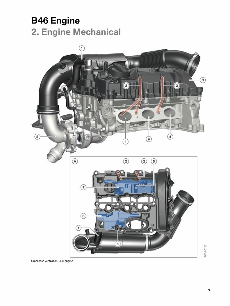
Crankcase�ventilation,�B38�engine
B46�Engine2.�Engine�Mechanical
18
Index ExplanationA Cylinder�head�cover,�view�from�below1 Blow-by�channel�into�clean�air�pipe�(turbocharged�operation)2 Blow-by�channel�upstream�of�the�intake�valves
(naturally�aspirated�engine�operation)3 Cylinder�head�cover4 Intake�ports5 Oil�return6 Oil�separator�(turbocharged�operation)7 Oil�separator�(naturally�aspirated�engine�operation)8 Exhaust�turbocharger
The�crankcase�ventilation�in�B46�engine�has�a�two-stage�design.�This�means�that,�depending�on�theload�condition,�the�blow-by�gases�are�routed�via�different�channels.
Naturally�aspirated�engine�operation
During�naturally-aspirated�engine�operation,�the�blow-by�gases�upstream�of�the�intake�valves�arerouted�to�the�intake�port.
B46�Engine2.�Engine�Mechanical
19
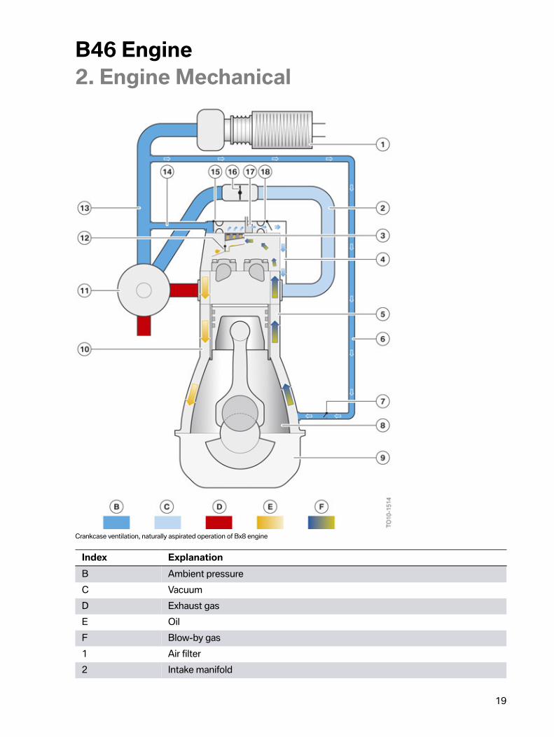
Crankcase�ventilation,�naturally�aspirated�operation�of�Bx8�engine
Index ExplanationB Ambient�pressureC VacuumD Exhaust�gasE OilF Blow-by�gas1 Air�filter2 Intake�manifold
B46�Engine2.�Engine�Mechanical
20
Index Explanation3 Separator4 Blow-by�channel�upstream�of�the�intake�valves5 Blow-by�channel�upstream�of�crankcase6 Purge�air�line7 Non-return�valve8 Crank�chamber9 Oil�sump10 Oil�return11 Exhaust�turbocharger12 Non-return�valve,�oil�return13 Clean�air�pipe14 Hose�to�clean�air�pipe15 Non-return�valve�with�restrictor16 Throttle�valve17 Pressure�control�valve18 Non-return�valve�with�restrictor
The�fine�oil�mist�is�separated�from�the�blow-by�gases�with�the�assistance�of�a�separator�and�the�oildroplets�formed�are�routed�back�to�the�oil�sump�via�the�oil�return.
The�throttle�valve�is�closed�during�naturally-aspirated�engine�operation.�This�produces�a�vacuum�inthe�intake�system.�which�draws�in�the�blow-by�gases�via�blow-by�channels�cast�into�the�cylinder�headdirectly�upstream�of�the�intake�valves.�In�systems�controlled�by�Valvetronic,�the�throttle�valve�is�alsolightly�shut�in�these�operating�conditions�to�guarantee�the�engine�ventilation�function.
A�purge�air�line,�which�is�connected�to�the�clean�air�pipe�ahead�of�the�exhaust�turbocharger�and�to�thecrankcase,�routes�fresh�air�via�a�non-return�valve�directly�into�the�crankcase�chamber.�The�bigger�thevacuum�in�the�crankcase,�the�bigger�the�air�mass�introduced�into�the�crankcase.�This�purging�preventsthe�pressure�control�valve�from�icing�up.
Charged�operation
As�a�significant�overpressure�prevails�in�the�intake�pipe�during�turbocharged�operation,�the�blow-bygases�cannot�be�introduced�upstream�of�the�intake�valves�in�the�intake�port.�The�blow-by�gases�aretherefore�introduced�into�the�clean�air�pipe�in�this�operating�condition.
B46�Engine2.�Engine�Mechanical
21
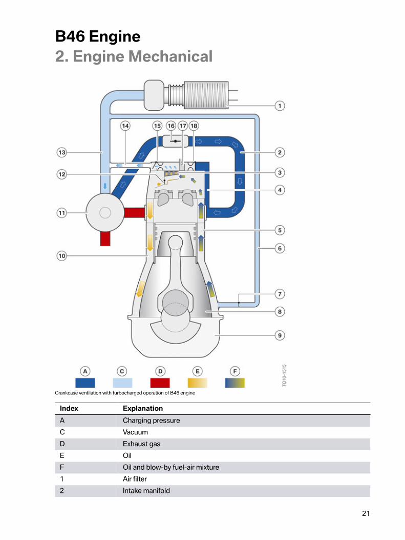
Crankcase�ventilation�with�turbocharged�operation�of�B46�engine
Index ExplanationA Charging�pressureC VacuumD Exhaust�gasE OilF Oil�and�blow-by�fuel-air�mixture1 Air�filter2 Intake�manifold
B46�Engine2.�Engine�Mechanical
22
Index Explanation3 Separator4 Blow-by�channel�upstream�of�the�intake�valves5 Blow-by�channel�upstream�of�crankcase6 Purge�air�line7 Non-return�valve8 Crank�chamber9 Oil�sump10 Oil�return11 Exhaust�turbocharger12 Non-return�valve,�oil�return13 Clean�air�pipe14 Hose�to�clean�air�pipe15 Non-return�valve�with�restrictor16 Throttle�valve17 Pressure�control�valve18 Non-return�valve�with�restrictor
The�fine�oil�mist�is�separated�from�the�blow-by�gases�with�the�assistance�of�a�separator�and�the�oildroplets�formed�are�routed�back�to�the�oil�sump�via�the�oil�return.
The�cylinder�head�cover�is�connected�to�the�clean�air�pipe�by�a�hose.�During�turbocharged�operation,a�vacuum�is�produced�in�the�clean�air�pipe.�This�vacuum�draws�the�blow-by�gases�into�the�clean�airpipe�via�the�hose.
Always�ensure�absolute�cleanliness�when�filling�the�engine�with�engine�oil.�Clean�the�oil�filler�neckbefore�you�screw�on�the�sealing�cap.�Engine�oil�residue�at�the�sealing�cap�may�lead�to�misdiagnosisat�the�crankcase�ventilation.
2.1.2.�Cylinder�head
Technical�features:
• Material:�AlSi7MgCU0.5• Coolant�cooling�according�to�the�cross-flow�principle• Four�valves�per�cylinder• Mounting�of�the�valve�gear• Mounting�of�the�Valvetronic�and�the�Valvetronic�servomotor• Mounting�of�the�high�pressure�pump
B46�Engine2.�Engine�Mechanical
23
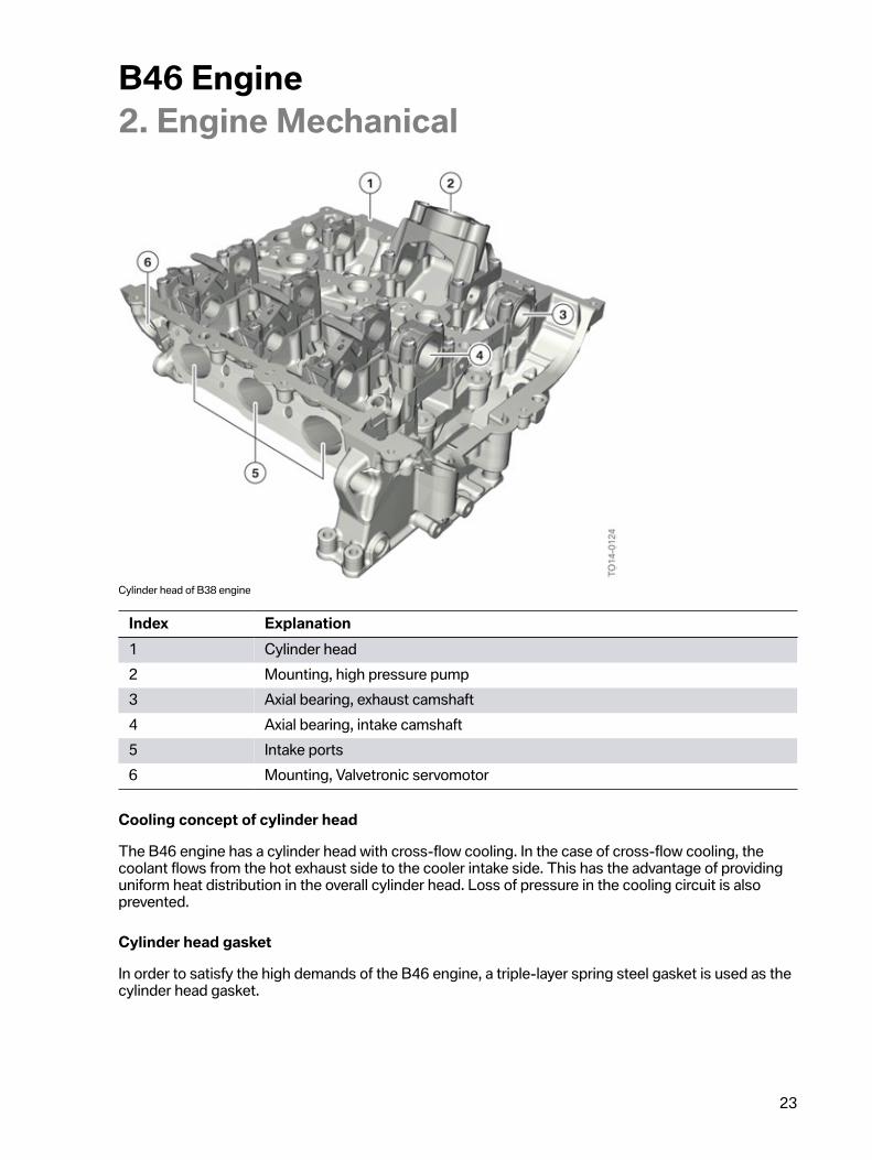
Cylinder�head�of�B38�engine
Index Explanation1 Cylinder�head2 Mounting,�high�pressure�pump3 Axial�bearing,�exhaust�camshaft4 Axial�bearing,�intake�camshaft5 Intake�ports6 Mounting,�Valvetronic�servomotor
Cooling�concept�of�cylinder�head
The�B46�engine�has�a�cylinder�head�with�cross-flow�cooling.�In�the�case�of�cross-flow�cooling,�thecoolant�flows�from�the�hot�exhaust�side�to�the�cooler�intake�side.�This�has�the�advantage�of�providinguniform�heat�distribution�in�the�overall�cylinder�head.�Loss�of�pressure�in�the�cooling�circuit�is�alsoprevented.
Cylinder�head�gasket
In�order�to�satisfy�the�high�demands�of�the�B46�engine,�a�triple-layer�spring�steel�gasket�is�used�as�thecylinder�head�gasket.
B46�Engine2.�Engine�Mechanical
24
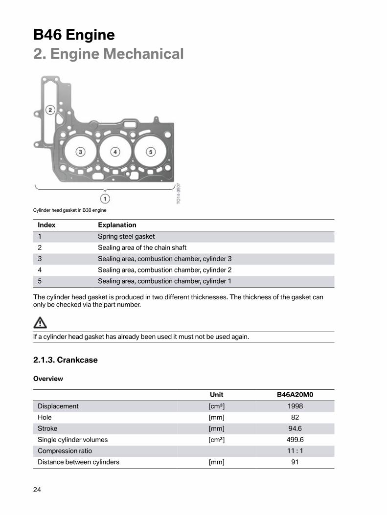
Cylinder�head�gasket�in�B38�engine
Index Explanation1 Spring�steel�gasket2 Sealing�area�of�the�chain�shaft3 Sealing�area,�combustion�chamber,�cylinder�34 Sealing�area,�combustion�chamber,�cylinder�25 Sealing�area,�combustion�chamber,�cylinder�1
The�cylinder�head�gasket�is�produced�in�two�different�thicknesses.�The�thickness�of�the�gasket�canonly�be�checked�via�the�part�number.
If�a�cylinder�head�gasket�has�already�been�used�it�must�not�be�used�again.
2.1.3.�Crankcase
Overview
Unit B46A20M0Displacement [cm³] 1998Hole [mm] 82Stroke [mm] 94.6Single�cylinder�volumes [cm³] 499.6Compression�ratio 11�:�1Distance�between�cylinders [mm] 91
B46�Engine2.�Engine�Mechanical
25
Overview
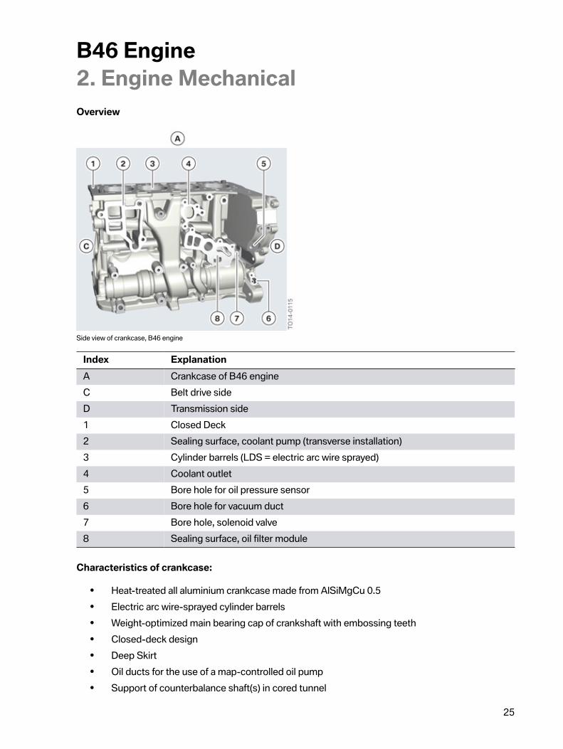
Side�view�of�crankcase,�B46�engine
Index ExplanationA Crankcase�of�B46�engineC Belt�drive�sideD Transmission�side1 Closed�Deck2 Sealing�surface,�coolant�pump�(transverse�installation)3 Cylinder�barrels�(LDS�=�electric�arc�wire�sprayed)4 Coolant�outlet5 Bore�hole�for�oil�pressure�sensor6 Bore�hole�for�vacuum�duct7 Bore�hole,�solenoid�valve8 Sealing�surface,�oil�filter�module
Characteristics�of�crankcase:
• Heat-treated�all�aluminium�crankcase�made�from�AlSiMgCu�0.5• Electric�arc�wire-sprayed�cylinder�barrels• Weight-optimized�main�bearing�cap�of�crankshaft�with�embossing�teeth• Closed-deck�design• Deep�Skirt• Oil�ducts�for�the�use�of�a�map-controlled�oil�pump• Support�of�counterbalance�shaft(s)�in�cored�tunnel
B46�Engine2.�Engine�Mechanical
26
Electric�arc�wire�spraying�(LDS)
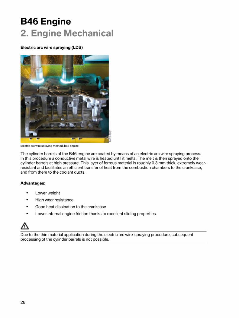
Electric�arc�wire�spraying�method,�Bx8�engine
The�cylinder�barrels�of�the�B46�engine�are�coated�by�means�of�an�electric�arc�wire�spraying�process.In�this�procedure�a�conductive�metal�wire�is�heated�until�it�melts.�The�melt�is�then�sprayed�onto�thecylinder�barrels�at�high�pressure.�This�layer�of�ferrous�material�is�roughly�0.3�mm�thick,�extremely�wear-resistant�and�facilitates�an�efficient�transfer�of�heat�from�the�combustion�chambers�to�the�crankcase,and�from�there�to�the�coolant�ducts.
Advantages:
• Lower�weight• High�wear�resistance• Good�heat�dissipation�to�the�crankcase• Lower�internal�engine�friction�thanks�to�excellent�sliding�properties
Due�to�the�thin�material�application�during�the�electric�arc�wire-spraying�procedure,�subsequentprocessing�of�the�cylinder�barrels�is�not�possible.
B46�Engine2.�Engine�Mechanical
27
Bearing,�counterbalance�shaft
Crankcase�from�below,�Bx8�engine
Index ExplanationA Crankcase�of�B46�engine1 Position�of�counterbalance�shaft�12 Cylinder�barrel�(coated�by�electric�arc�wire�spraying)3 Embossed�main�bearing�cap4 Main�bearing�seat5 Ventilation�holes6 Position�of�counterbalance�shaft�2
In�the�4-cylinder�engine,�these�forces�are�reduced�by�two�counter-rotating�counterbalance�shafts.�Formore�information,�refer�to�the�chapter�on�Counterbalance�shafts.
Closed�Deck
With�the�closed-deck�design,�the�coolant�ducts�around�the�cylinder�are�closed�from�above�andprovided�with�coolant�bore�holes.
B46�Engine2.�Engine�Mechanical
28
Deep�Skirt
With�the�"deep�skirt"�concept,�the�side�walls�extend�far�downwards.�This�lends�the�crankcase�a�highdegree�of�stability�and�considerable�flexibility�in�terms�of�the�piston�stroke�length.
Embossed�crankshaft�bearing�cap
The�weight�of�the�main�bearing�cap�of�the�crankshaft�has�been�further�optimized�for�the�new�B46engine.�When�the�impression�connection�is�made�the�main�bearing�cap�is�designed�with�a�profile.When�the�main�bearing�bolts�are�tightened�for�the�first�time,�this�profile�pushes�into�the�surface�ofthe�bearing�block�on�the�crankcase�side.
Exchange�of�the�main�bearing�cap,�or�positioning�in�another�bearing�position�on�the�crankshaft,is�not�permitted�and�will�lead�to�engine�damage.
Ventilation�holes
The�combustion�chambers�are�connected�via�ventilation�bore�holes�at�the�bottom�end�of�the�cylinderbarrels.�The�air�flows,�which�arise�as�a�result�of�the�upward�and�downward�movement�of�the�pistons,can�thus�escape�easier�via�the�ventilation�bore�holes.�In�addition,�as�the�displacement�of�air�volume�hasbeen�simplified�by�using�the�ventilation�bore�holes,�the�piston�can�move�up�and�down�more�easily.This�reduces�the�internal�friction�of�the�engine�and�ensures�the�engine�operates�more�efficiently.
2.1.4.�Oil�sumpThe�oil�sump�is�manufactured�from�die-cast�aluminium.
Tasks:
• Collecting�vessel�for�engine�oil.• Collection�area�for�returning�engine�oil.• Reinforcing�component�in�the�engine-transmission�combination.• Fixture�for�the�oil-level�sensor�and�oil�drain�plug.• Connection�of�the�anti-roll�bar�link�for�transverse�mounting.
B46�Engine2.�Engine�Mechanical
29
Side�view�of�B38�engine
Index Explanation1 Attachment�points,�crankcase�at�transmission2 Timing�case�cover3 Seal�plug�for�bore�hole�of�the�holding�fixture4 Attachment�points,�oil�sump�at�transmission5 Oil�sump6 Anti-roll�bar�link�(only�for�transverse�mounting)7 Oil�level�sensor
The�engine�can�be�disconnected�via�a�bore�hole�in�the�oil�sump�for�adjusting�the�timing.�Wheninstalling�the�oil�sump�with�the�transmission�removed,�make�sure�that�the�transmission�contact�surfaceof�the�oil�sump�and�the�timing�case�cover�are�in�one�plane.�Always�use�the�corresponding�specialtool.�If�a�gap�arises�between�the�two�areas�when�tightening�the�mounting�bolts�of�the�transmission,�itcauses�damage�to�the�oil�sump.
B46�Engine2.�Engine�Mechanical
30
Oil�sump�of�B38�engine
Index Explanation1 Anti-roll�bar�link�(only�for�transverse�mounting)2 Oil�drain�plug3 Oil�sump4 Oil�level�sensor5 Reinforcing�ribs6 Connection�of�anti-roll�bar�link�at�oil�sump7 Oil�return�to�oil�sump8 Crankcase�end�cover�(belt�side)
The�engine�oil�flows�from�the�oil�circuit�back�to�the�oil�sump�via�the�return�line�of�the�exhaustturbocharger.
The�B46�engine�does�not�have�an�oil�dipstick.�The�oil�level�is�monitored�electronically�at�all�timeswith�the�assistance�of�the�oil-level�sensor�and�can�be�requested�via�the�on-board�computer.
B46�Engine2.�Engine�Mechanical
31
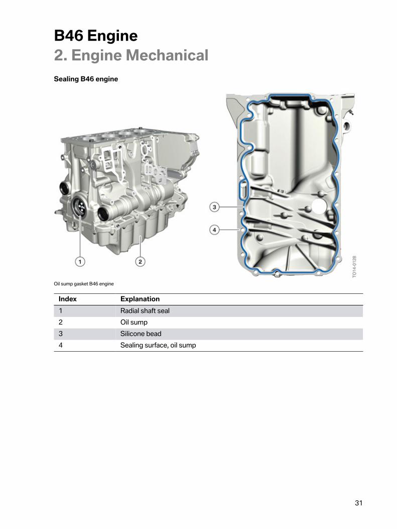
Sealing�B46�engine
Oil�sump�gasket�B46�engine
Index Explanation1 Radial�shaft�seal2 Oil�sump3 Silicone�bead4 Sealing�surface,�oil�sump
B46�Engine2.�Engine�Mechanical
32
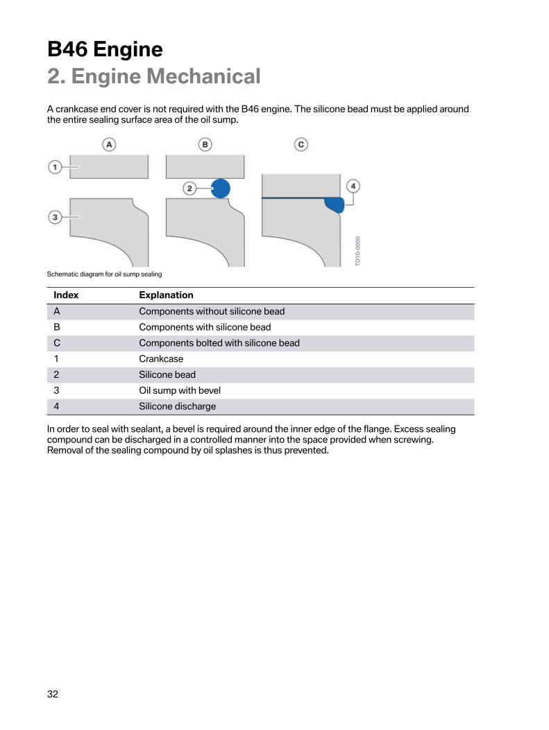
A�crankcase�end�cover�is�not�required�with�the�B46�engine.�The�silicone�bead�must�be�applied�aroundthe�entire�sealing�surface�area�of�the�oil�sump.
Schematic�diagram�for�oil�sump�sealing
Index ExplanationA Components�without�silicone�beadB Components�with�silicone�beadC Components�bolted�with�silicone�bead1 Crankcase2 Silicone�bead3 Oil�sump�with�bevel4 Silicone�discharge
In�order�to�seal�with�sealant,�a�bevel�is�required�around�the�inner�edge�of�the�flange.�Excess�sealingcompound�can�be�discharged�in�a�controlled�manner�into�the�space�provided�when�screwing.Removal�of�the�sealing�compound�by�oil�splashes�is�thus�prevented.
B46�Engine2.�Engine�Mechanical
33
2.2.�Crankshaft�drive
2.2.1.�Crankshaft
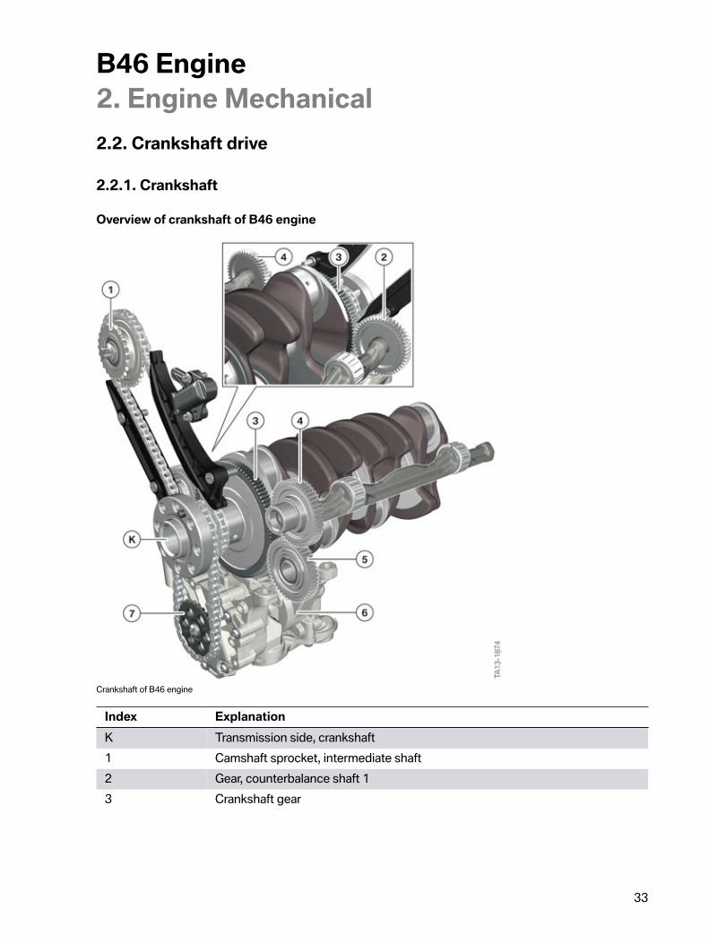
Overview�of�crankshaft�of�B46�engine
Crankshaft�of�B46�engine
Index ExplanationK Transmission�side,�crankshaft1 Camshaft�sprocket,�intermediate�shaft2 Gear,�counterbalance�shaft�13 Crankshaft�gear
B46�Engine2.�Engine�Mechanical
34
Index Explanation4 Gear,�counterbalance�shaft�25 Intermediate�gear�(change�in�direction�of�rotation�of�counterbalance�shaft�2)6 Oil�and�vacuum�pump7 Oil�pump�sprocket
In�the�B46�engine�both�the�timing�chain�and�the�drive�for�the�counterbalance�shafts�are�located�on�thetransmission�side�of�the�crankshaft.
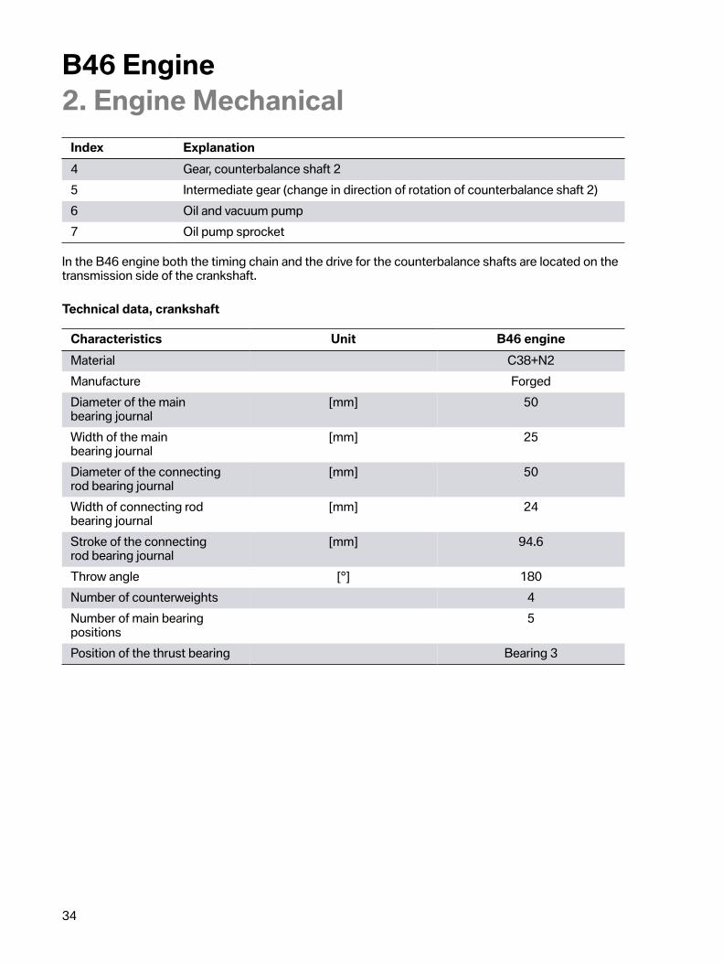
Technical�data,�crankshaft
Characteristics Unit B46�engineMaterial C38+N2Manufacture ForgedDiameter�of�the�mainbearing�journal
[mm] 50
Width�of�the�mainbearing�journal
[mm] 25
Diameter�of�the�connectingrod�bearing�journal
[mm] 50
Width�of�connecting�rodbearing�journal
[mm] 24
Stroke�of�the�connectingrod�bearing�journal
[mm] 94.6
Throw�angle [°] 180Number�of�counterweights 4Number�of�main�bearingpositions
5
Position�of�the�thrust�bearing Bearing�3
B46�Engine2.�Engine�Mechanical
35
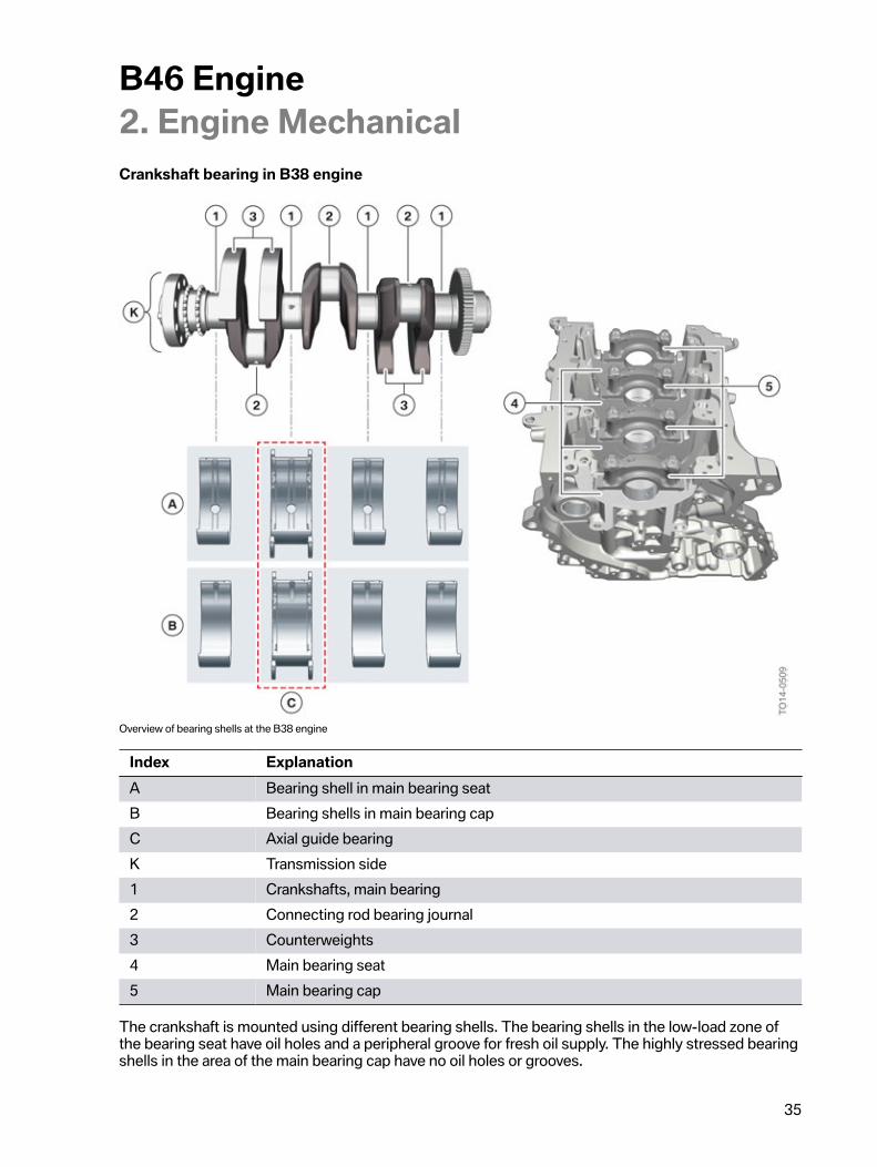
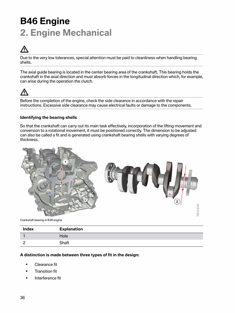
Crankshaft�bearing�in�B38�engine
Overview�of�bearing�shells�at�the�B38�engine
Index ExplanationA Bearing�shell�in�main�bearing�seatB Bearing�shells�in�main�bearing�capC Axial�guide�bearingK Transmission�side1 Crankshafts,�main�bearing2 Connecting�rod�bearing�journal3 Counterweights4 Main�bearing�seat5 Main�bearing�cap
The�crankshaft�is�mounted�using�different�bearing�shells.�The�bearing�shells�in�the�low-load�zone�ofthe�bearing�seat�have�oil�holes�and�a�peripheral�groove�for�fresh�oil�supply.�The�highly�stressed�bearingshells�in�the�area�of�the�main�bearing�cap�have�no�oil�holes�or�grooves.
B46�Engine2.�Engine�Mechanical
36
Due�to�the�very�low�tolerances,�special�attention�must�be�paid�to�cleanliness�when�handling�bearingshells.
The�axial�guide�bearing�is�located�in�the�center�bearing�area�of�the�crankshaft.�This�bearing�holds�thecrankshaft�in�the�axial�direction�and�must�absorb�forces�in�the�longitudinal�direction�which,�for�example,can�arise�during�the�operation�the�clutch.
Before�the�completion�of�the�engine,�check�the�side�clearance�in�accordance�with�the�repairinstructions.�Excessive�side�clearance�may�cause�electrical�faults�or�damage�to�the�components.
Identifying�the�bearing�shells
So�that�the�crankshaft�can�carry�out�its�main�task�effectively,�incorporation�of�the�lifting�movement�andconversion�to�a�rotational�movement,�it�must�be�positioned�correctly.�The�dimension�to�be�adjustedcan�also�be�called�a�fit�and�is�generated�using�crankshaft�bearing�shells�with�varying�degrees�ofthickness.
Crankshaft�bearing�in�B38�engine
Index Explanation1 Hole2 Shaft
A�distinction�is�made�between�three�types�of�fit�in�the�design:
• Clearance�fit• Transition�fit• Interference�fit
B46�Engine2.�Engine�Mechanical
37
The�fit�is�viewed�as�an�accurate�relationship�between�the�bore�hole�and�the�shaft.�The�crankcaserepresents�the�bore�hole�and�the�crankshaft�represents�the�shaft.�This�is�why�the�numbers�for�theclassification�of�the�bearing�shells�are�located�on�the�crankcase�and�the�crankshaft.�In�the�case�of�adimension�being�adjusted,�this�is�a�so-called�clearance�fit.�A�clearance�fit�is�characterized�by�the�factthat�in�each�case�the�minimum�dimension�of�the�bore�hole�is�greater�than�the�maximum�dimension�ofthe�shaft.�This�creates�the�necessary�play�between�the�shaft�and�the�bore�hole,�which�is�needed�forthe�bearing�of�the�crankshaft.
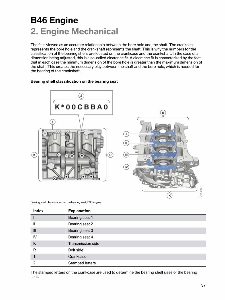
Bearing�shell�classification�on�the�bearing�seat
Bearing�shell�classification�on�the�bearing�seat,�B38�engine
Index ExplanationI Bearing�seat�1II Bearing�seat�2III Bearing�seat�3IV Bearing�seat�4K Transmission�sideR Belt�side1 Crankcase2 Stamped�letters
The�stamped�letters�on�the�crankcase�are�used�to�determine�the�bearing�shell�sizes�of�the�bearingseat.
B46�Engine2.�Engine�Mechanical
38
The�following�letters�are�used�for�the�classification:
• A�=�highest�possible�play�(thinnest�bearing�shell)• B�=�medium�play�(medium�bearing�shell)• C�=�lowest�possible�play�(thickest�bearing�shell).
The�letter�K�stands�for�the�transmission�side�of�the�crankcase.�It�also�specifies�the�counting�order�forthe�assignment.
If�there�is�a�K�before�the�stamped�letters,�then�the�first�letter�of�the�code�refers�to�the�bearing�shell�ofbearing�seat�4,�which�is�located�on�the�transmission�side.�The�subsequent�letters,�read�from�left�toright,�refer�to�the�bearing�seat�3,�2�and�1.�The�positions�marked�with�"0"�are�placeholders�for�largerengines�and�are�simply�omitted.
Using�the�previous�graphic�for�reference,�the�following�combination�is�obtained:
Assignment:
• Transmission�side�=�K• Bearing�seat�4�=�C• Bearing�seat�3�=�B• Bearing�seat�2�=�B• Bearing�seat�1�=�A.
If�the�stamped�letters�are�not�preceded�by�"K",�then�the�first�letter�of�the�code�refers�to�the�bearingshell�of�bearing�seat�1,�which�is�located�opposite�the�transmission�side�on�the�belt�side.�Thesubsequent�letters,�read�from�left�to�right,�refer�to�bearing�seat�2,�3�and�4.
When�assigning�the�letters�without�"K",�the�following�combination�is�obtained:
Assignment:
• Bearing�seat�1�=�C• Bearing�seat�2�=�B• Bearing�seat�3�=�B• Bearing�seat�4�=�A.
B46�Engine2.�Engine�Mechanical
39
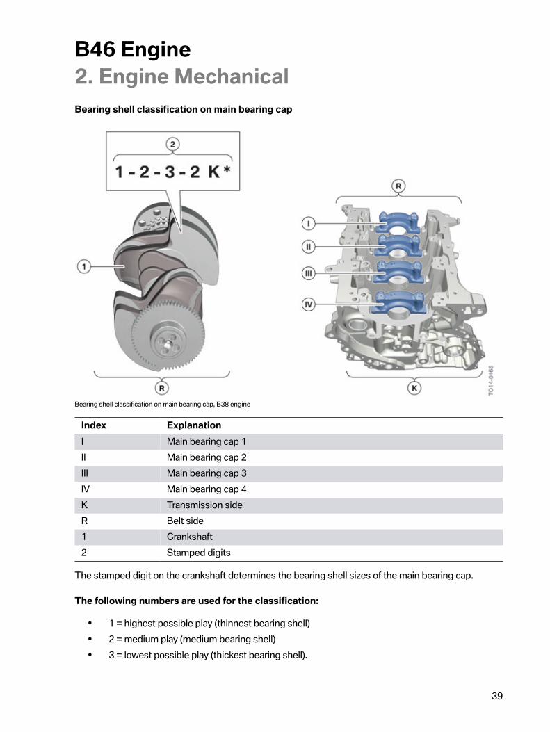
Bearing�shell�classification�on�main�bearing�cap
Bearing�shell�classification�on�main�bearing�cap,�B38�engine
Index ExplanationI Main�bearing�cap�1II Main�bearing�cap�2III Main�bearing�cap�3IV Main�bearing�cap�4K Transmission�sideR Belt�side1 Crankshaft2 Stamped�digits
The�stamped�digit�on�the�crankshaft�determines�the�bearing�shell�sizes�of�the�main�bearing�cap.
The�following�numbers�are�used�for�the�classification:
• 1�=�highest�possible�play�(thinnest�bearing�shell)• 2�=�medium�play�(medium�bearing�shell)• 3�=�lowest�possible�play�(thickest�bearing�shell).
B46�Engine2.�Engine�Mechanical
40
In�the�case�of�the�crankshaft,�the�letter�K�also�defines�the�assignment�of�the�bearing�position.The�digit�next�to�the�K�is�to�be�assigned�to�the�main�bearing�cap�4�which�is�on�the�transmission�side.The�subsequent�digits,�read�from�left�to�right,�refer�to�the�main�bearing�cap�3,�2�and�1.
Using�the�previous�graphic�for�reference,�the�following�combination�is�obtained:
Assignment:
• Main�bearing�cap�1�=�1• Main�bearing�cap�2�=�2• Main�bearing�cap�3�=�3• Main�bearing�cap�4�=�2• Transmission�side�=�K.
Deciphering�the�combination�of�letters�and�digits
The�letter�and�digit�combination�of�the�main�bearing�shells�can�be�decrypted�using�a�table�in�the�repairinstructions.�The�correct�bearing�shell�sizes�are�determined�with�help�of�the�color�codes.
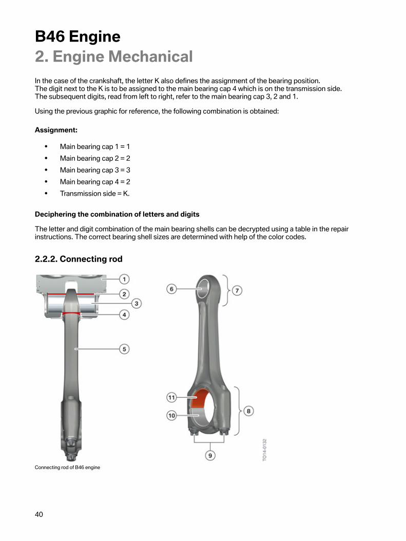
2.2.2.�Connecting�rod
Connecting�rod�of�B46�engine
B46�Engine2.�Engine�Mechanical
41
Index Explanation1 Piston2 Force-transmitting�surface3 Wrist�pin4 Connecting�rod�bearing�bush�with�shaped�bore�hole5 Connecting�rod6 Connecting�rod�bush7 Small�connecting�rod�eye�(trapezoidal�shape)8 Large�connecting�rod�eye�(cracked)9 Connecting�rod�bolts�of�the�connecting�rod�bearing�cap10 Connecting�rod�bearing�shell�of�the�connecting�rod�bearing�cap11 Connecting�rod�bearing�shell�of�the�connecting�rod�(IROX-coated)
The�familiar�drop-forged�cracked�connecting�rods�are�used.
If�a�connecting�rod�bearing�cap�is�mounted�the�wrong�way�round�or�on�another�connecting�rod,�thefracture�structure�of�both�parts�is�destroyed�and�the�connecting�rod�bearing�cap�is�not�centerd.�In�thisevent�the�entire�connecting�rod�set�must�be�replaced�with�new�parts.�In�Service�please�observe�thespecified�jointing�torques�and�angle�of�rotation�specifications�in�the�repair�instructions.
Weight�classification
To�guarantee�smooth�engine�running,�the�connecting�rods�are�divided�into�weight�classes.�The�largeand�small�connecting�rod�eyes�are�weighed�separately�and�divided�into�various�classes�according�totheir�weight.
In�Service�only�connecting�rods�of�the�same�weight�class�can�be�used.�This�is�why�only�a�full�set�ofconnecting�rods�is�available�in�the�event�of�a�replacement.�This�set�comprises�the�correspondingnumber�of�connecting�rods�of�a�weight�classification.
Irox-coating
In�order�to�comply�with�the�increasingly�stringent�exhaust�emission�regulations,�most�combustionengines�nowadays�are�equipped�with�an�automatic�engine�start-stop�function.�This�has�led�to�a�hugeincrease�in�starting�cycles.
To�ensure�the�engine�runs�smoothly,�it�is�important�that�sufficient�lubricating�oil�is�supplied�to�thebearing�positions�of�the�crankshaft.�If�the�oil�supply�can�be�ensured,�solid�body�contact�will�notoccur�between�the�connecting�rod�bearing�journal�and�connecting�rod�bearing�shell�due�to�the�thinlubricating�film.
B46�Engine2.�Engine�Mechanical
42
If�the�engine�is�now�stopped,�it�will�not�be�possible�for�the�mechanically-driven�oil�pump�to�maintainthe�oil�supply.�The�oil�film�between�the�bearing�positions�flows�off.�Solid�body�contact�occurs�betweenthe�connecting�rod�bearing�journal�and�connecting�rod�bearing�shell.�Once�the�engine�is�restarted,it�takes�a�certain�amount�of�time�for�the�lubricating�film�to�fully�re-establish�itself.�The�connectingrod�bearing�shell�may�be�subject�to�wear�in�this�short�period.�The�Irox-coating�reduces�this�wear�to�aminimum.
The�IROX-coated�bearing�shells�are�only�located�on�the�connecting�rod�side�as�here�the�load�actsmainly�on�the�bearing�shells.�The�bearing�shell�caps�are�equipped�with�a�bearing�shell�without�IROXcoating.
The�IROX�ball�bearings�are�red�due�to�their�special�coating.
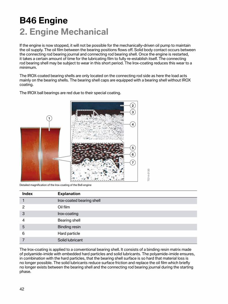
Detailed�magnification�of�the�Irox-coating�of�the�Bx8�engine
Index Explanation1 Irox-coated�bearing�shell2 Oil�film3 Irox-coating4 Bearing�shell5 Binding�resin6 Hard�particle7 Solid�lubricant
The�Irox-coating�is�applied�to�a�conventional�bearing�shell.�It�consists�of�a�binding�resin�matrix�madeof�polyamide-imide�with�embedded�hard�particles�and�solid�lubricants.�The�polyamide-imide�ensures,in�combination�with�the�hard�particles,�that�the�bearing�shell�surface�is�so�hard�that�material�loss�isno�longer�possible.�The�solid�lubricants�reduce�surface�friction�and�replace�the�oil�film�which�brieflyno�longer�exists�between�the�bearing�shell�and�the�connecting�rod�bearing�journal�during�the�startingphase.
B46�Engine2.�Engine�Mechanical
43
Bearing�shell�classification�of�connecting�rod�bearing
The�connecting�rod�bearing�shells�are�available�in�one�standard�size.�It�is�therefore�not�necessary�tofollow�a�procedure�similar�to�that�used�with�the�main�bearing�shells�of�the�crankshaft.
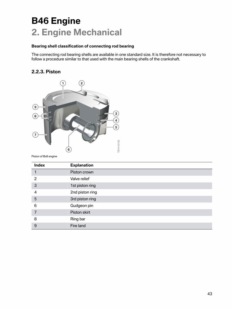
2.2.3.�Piston
Piston�of�Bx8�engine
Index Explanation1 Piston�crown2 Valve�relief3 1st�piston�ring4 2nd�piston�ring5 3rd�piston�ring6 Gudgeon�pin7 Piston�skirt8 Ring�bar9 Fire�land
B46�Engine2.�Engine�Mechanical
44
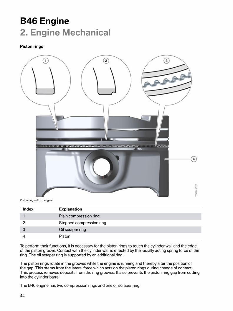
Piston�rings
Piston�rings�of�Bx8�engine
Index Explanation1 Plain�compression�ring2 Stepped�compression�ring3 Oil�scraper�ring4 Piston
To�perform�their�functions,�it�is�necessary�for�the�piston�rings�to�touch�the�cylinder�wall�and�the�edgeof�the�piston�groove.�Contact�with�the�cylinder�wall�is�effected�by�the�radially�acting�spring�force�of�thering.�The�oil�scraper�ring�is�supported�by�an�additional�ring.
The�piston�rings�rotate�in�the�grooves�while�the�engine�is�running�and�thereby�alter�the�position�ofthe�gap.�This�stems�from�the�lateral�force�which�acts�on�the�piston�rings�during�change�of�contact.This�process�removes�deposits�from�the�ring�grooves.�It�also�prevents�the�piston�ring�gap�from�cuttinginto�the�cylinder�barrel.
The�B46�engine�has�two�compression�rings�and�one�oil�scraper�ring.
B46�Engine2.�Engine�Mechanical
45
The�plain�rectangular�compression�ring�sits�in�the�first�piston�ring�groove�and�is�used�as�a�plaincompression�ring.
The�taper�faced�piston�ring�is�also�a�compression�ring.�A�sharp�wiper�edge�develops�through�the�lugfor�controlling�the�oil�supply.�The�undercut�of�the�lug�implies�that�the�oil�scraped�from�the�running�edgeis�diverted�and�an�oil�blockage�does�not�form�there,�which�would�otherwise�reduce�the�scraping�effect.
The�oil�scraper�ring�is�a�steel�band�ring�with�spring.�The�two�lands�and�in�particular�the�chamfer�createa�high�surface�contact�pressure,�which�promotes�the�oil-scraping�effect.
The�plain�rectangular�compression�ring�and�the�taper�faced�piston�ring�have�a�Top�mark.�Wheninstalling�the�two�piston�rings�the�Top�mark�must�be�facing�in�the�direction�of�the�piston�crown.
2.2.4.�Counterbalance�shaftsDue�to�the�operating�principle�of�the�piston�engine,�undesired�oscillations�occur�at�the�engine�housingwhen�driving,�which�can�be�transmitted�to�the�vehicle�interior.�To�counteract�this�negative�effect,�BMWhas�already�been�installing�so-called�counterbalance�shafts�in�more�recent�engine�generations.�Up�tillnow,�their�role�was�to�cancel�out�free�inertia�forces�and�therefore�increase�ride�comfort.�In�addition�tothe�inertia�forces,�so-called�'free�moments�of�inertia'�also�exist,�which�can�also�adversely�effect�ridecomfort.�Depending�on�the�engine�design�and�number�of�cylinders,�varying�degrees�of�free�inertiaforces�and�free�moments�of�inertia�occur.
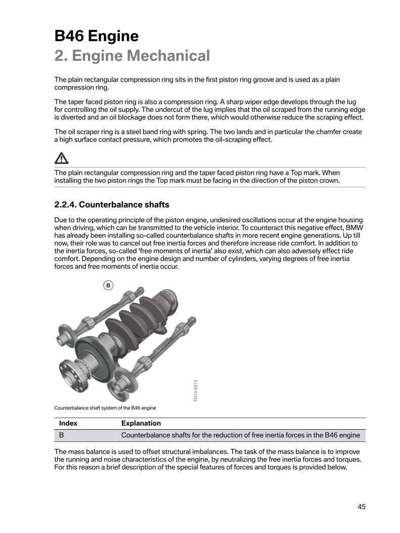
Counterbalance�shaft�system�of�the�B46�engine
Index ExplanationB Counterbalance�shafts�for�the�reduction�of�free�inertia�forces�in�the�B46�engine
The�mass�balance�is�used�to�offset�structural�imbalances.�The�task�of�the�mass�balance�is�to�improvethe�running�and�noise�characteristics�of�the�engine,�by�neutralizing�the�free�inertia�forces�and�torques.For�this�reason�a�brief�description�of�the�special�features�of�forces�and�torques�is�provided�below.
B46�Engine2.�Engine�Mechanical
46
Forces
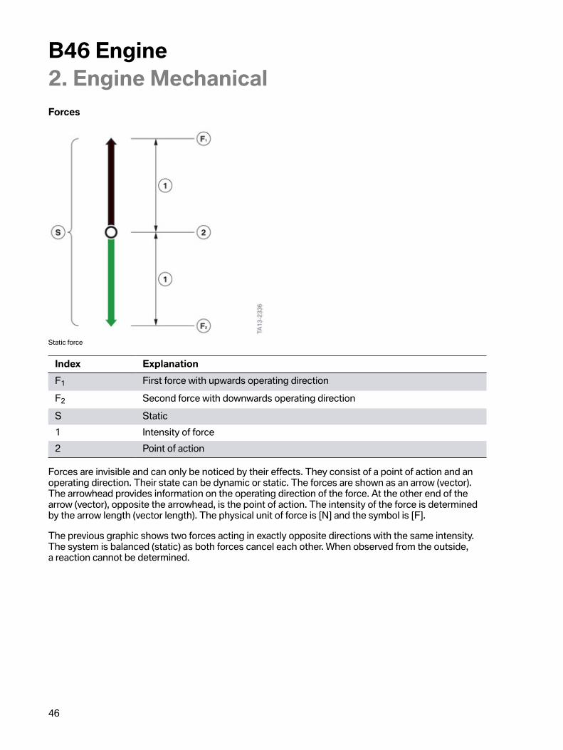
Static�force
Index ExplanationF1 First�force�with�upwards�operating�directionF2 Second�force�with�downwards�operating�directionS Static1 Intensity�of�force2 Point�of�action
Forces�are�invisible�and�can�only�be�noticed�by�their�effects.�They�consist�of�a�point�of�action�and�anoperating�direction.�Their�state�can�be�dynamic�or�static.�The�forces�are�shown�as�an�arrow�(vector).The�arrowhead�provides�information�on�the�operating�direction�of�the�force.�At�the�other�end�of�thearrow�(vector),�opposite�the�arrowhead,�is�the�point�of�action.�The�intensity�of�the�force�is�determinedby�the�arrow�length�(vector�length).�The�physical�unit�of�force�is�[N]�and�the�symbol�is�[F].
The�previous�graphic�shows�two�forces�acting�in�exactly�opposite�directions�with�the�same�intensity.The�system�is�balanced�(static)�as�both�forces�cancel�each�other.�When�observed�from�the�outside,a�reaction�cannot�be�determined.
B46�Engine2.�Engine�Mechanical
47
Torques
Static�torque
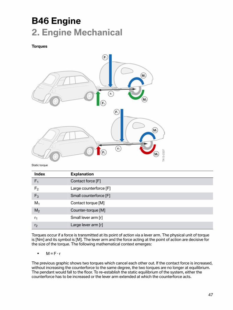
Index ExplanationF1 Contact�force�[F]F2 Large�counterforce�[F]F3 Small�counterforce�[F]M1 Contact�torque�[M]M2 Counter-torque�[M]r1 Small�lever�arm�[r]r2 Large�lever�arm�[r]
Torques�occur�if�a�force�is�transmitted�at�its�point�of�action�via�a�lever�arm.�The�physical�unit�of�torqueis�[Nm]�and�its�symbol�is�[M].�The�lever�arm�and�the�force�acting�at�the�point�of�action�are�decisive�forthe�size�of�the�torque.�The�following�mathematical�context�emerges:
• M�=�F�∙�r
The�previous�graphic�shows�two�torques�which�cancel�each�other�out.�If�the�contact�force�is�increased,without�increasing�the�counterforce�to�the�same�degree,�the�two�torques�are�no�longer�at�equilibrium.The�pendant�would�fall�to�the�floor.�To�re-establish�the�static�equilibrium�of�the�system,�either�thecounterforce�has�to�be�increased�or�the�lever�arm�extended�at�which�the�counterforce�acts.
B46�Engine2.�Engine�Mechanical
48
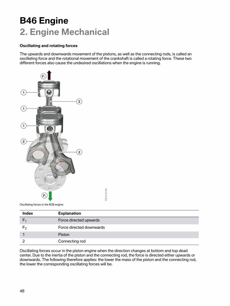
Oscillating�and�rotating�forces
The�upwards�and�downwards�movement�of�the�pistons,�as�well�as�the�connecting�rods,�is�called�anoscillating�force�and�the�rotational�movement�of�the�crankshaft�is�called�a�rotating�force.�These�twodifferent�forces�also�cause�the�undesired�oscillations�when�the�engine�is�running.
Oscillating�forces�in�the�B38�engine
Index ExplanationF1 Force�directed�upwardsF2 Force�directed�downwards1 Piston2 Connecting�rod
Oscillating�forces�occur�in�the�piston�engine�when�the�direction�changes�at�bottom�and�top�deadcenter.�Due�to�the�inertia�of�the�piston�and�the�connecting�rod,�the�force�is�directed�either�upwards�ordownwards.�The�following�therefore�applies:�the�lower�the�mass�of�the�piston�and�the�connecting�rod,the�lower�the�corresponding�oscillating�forces�will�be.
B46�Engine2.�Engine�Mechanical
49
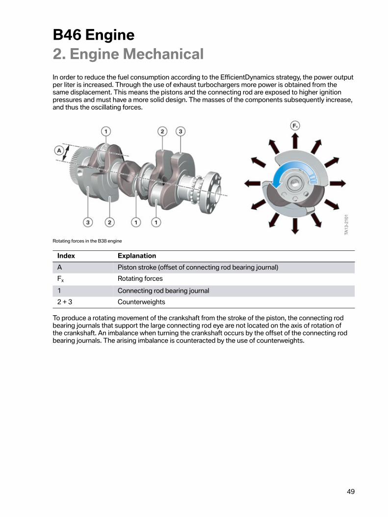
In�order�to�reduce�the�fuel�consumption�according�to�the�EfficientDynamics�strategy,�the�power�outputper�liter�is�increased.�Through�the�use�of�exhaust�turbochargers�more�power�is�obtained�from�thesame�displacement.�This�means�the�pistons�and�the�connecting�rod�are�exposed�to�higher�ignitionpressures�and�must�have�a�more�solid�design.�The�masses�of�the�components�subsequently�increase,and�thus�the�oscillating�forces.
Rotating�forces�in�the�B38�engine
Index ExplanationA Piston�stroke�(offset�of�connecting�rod�bearing�journal)Fx Rotating�forces1 Connecting�rod�bearing�journal2�+�3 Counterweights
To�produce�a�rotating�movement�of�the�crankshaft�from�the�stroke�of�the�piston,�the�connecting�rodbearing�journals�that�support�the�large�connecting�rod�eye�are�not�located�on�the�axis�of�rotation�ofthe�crankshaft.�An�imbalance�when�turning�the�crankshaft�occurs�by�the�offset�of�the�connecting�rodbearing�journals.�The�arising�imbalance�is�counteracted�by�the�use�of�counterweights.
B46�Engine2.�Engine�Mechanical
50
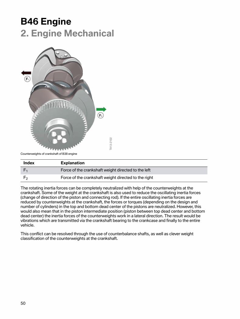
Counterweights�of�crankshaft�of�B38�engine
Index ExplanationF1 Force�of�the�crankshaft�weight�directed�to�the�leftF2 Force�of�the�crankshaft�weight�directed�to�the�right
The�rotating�inertia�forces�can�be�completely�neutralized�with�help�of�the�counterweights�at�thecrankshaft.�Some�of�the�weight�at�the�crankshaft�is�also�used�to�reduce�the�oscillating�inertia�forces(change�of�direction�of�the�piston�and�connecting�rod).�If�the�entire�oscillating�inertia�forces�arereduced�by�counterweights�at�the�crankshaft,�the�forces�or�torques�(depending�on�the�design�andnumber�of�cylinders)�in�the�top�and�bottom�dead�center�of�the�pistons�are�neutralized.�However,�thiswould�also�mean�that�in�the�piston�intermediate�position�(piston�between�top�dead�center�and�bottomdead�center)�the�inertia�forces�of�the�counterweights�work�in�a�lateral�direction.�The�result�would�bevibrations�which�are�transmitted�via�the�crankshaft�bearing�to�the�crankcase�and�finally�to�the�entirevehicle.
This�conflict�can�be�resolved�through�the�use�of�counterbalance�shafts,�as�well�as�clever�weightclassification�of�the�counterweights�at�the�crankshaft.
B46�Engine2.�Engine�Mechanical
51
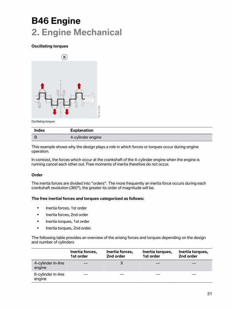
Oscillating�torques
Oscillating�torques
Index ExplanationB 4-cylinder�engine
This�example�shows�why�the�design�plays�a�role�in�which�forces�or�torques�occur�during�engineoperation.
In�contrast,�the�forces�which�occur�at�the�crankshaft�of�the�4-cylinder�engine�when�the�engine�isrunning�cancel�each�other�out.�Free�moments�of�inertia�therefore�do�not�occur.
Order
The�inertia�forces�are�divided�into�"orders".�The�more�frequently�an�inertia�force�occurs�during�eachcrankshaft�revolution�(360°),�the�greater�its�order�of�magnitude�will�be.
The�free�inertial�forces�and�torques�categorized�as�follows:
• Inertia�forces,�1st�order• Inertia�forces,�2nd�order• Inertia�torques,�1st�order• Inertia�torques,�2nd�order.
The�following�table�provides�an�overview�of�the�arising�forces�and�torques�depending�on�the�designand�number�of�cylinders
Inertia�forces,1st�order
Inertia�forces,2nd�order
Inertia�torques,1st�order
Inertia�torques,2nd�order
4-cylinder�in-lineengine
— X — —
6-cylinder�in-lineengine
— — — —
B46�Engine2.�Engine�Mechanical
52
The�table�provides�information�on�which�forces�and�torques�occur�and�their�order�of�magnitude.�Freeinertial�forces�and�moments�of�inertia�of�the�first�order�are�the�most�noticeable.�Free�inertia�forces�andmoments�of�inertia�of�the�second�order�are�perceived�is�much�less�troublesome.�The�greater�the�orderof�magnitude�is�therefore,�the�more�it�can�be�disregarded�for�the�purposes�of�mass�balancing.
The�table�shows�that�the�best�engine�design�in�terms�of�smooth�running�is�the�6-cylinder�in-lineengine.�All�forces�cancel�each�other�out.�Therefore,�with�this�engine�design�no�additional�measures�forneutralizing�the�rotating�or�oscillating�masses�have�to�be�implemented.
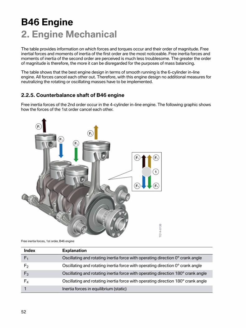
2.2.5.�Counterbalance�shaft�of�B46�engineFree�inertia�forces�of�the�2nd�order�occur�in�the�4-cylinder�in-line�engine.�The�following�graphic�showshow�the�forces�of�the�1st�order�cancel�each�other.
Free�inertia�forces,�1st�order,�B46�engine
Index ExplanationF1 Oscillating�and�rotating�inertia�force�with�operating�direction�0°�crank�angleF2 Oscillating�and�rotating�inertia�force�with�operating�direction�0°�crank�angleF3 Oscillating�and�rotating�inertia�force�with�operating�direction�180°�crank�angleF4 Oscillating�and�rotating�inertia�force�with�operating�direction�180°�crank�angle1 Inertia�forces�in�equilibrium�(static)
B46�Engine2.�Engine�Mechanical
53
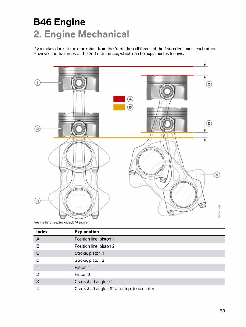
If�you�take�a�look�at�the�crankshaft�from�the�front,�then�all�forces�of�the�1st�order�cancel�each�other.However,�inertia�forces�of�the�2nd�order�occur,�which�can�be�explained�as�follows:
Free�inertia�forces,�2nd�order,�B46�engine
Index ExplanationA Position�line,�piston�1B Position�line,�piston�2C Stroke,�piston�1D Stroke,�piston�21 Piston�12 Piston�23 Crankshaft�angle�0°4 Crankshaft�angle�45°�after�top�dead�center
B46�Engine2.�Engine�Mechanical
54
As�can�be�seen�in�the�previous�graphic,�both�pistons�are�at�top�or�bottom�dead�center�at�the�sametime.�If�the�crankshaft�is�rotated�45°�counter-clockwise�and�the�two�piston�positions�are�compared,�itbecomes�clear�that�the�paths�covered�by�both�pistons�differ.�Piston�1,�which�started�from�the�top�deadcenter�position,�covers�a�greater�distance�than�piston�2�from�the�bottom�dead�center�position.�As�bothpistons�cover�a�different�distance�in�the�same�period,�they�must�have�travelled�at�different�speeds.�Thisspeed�difference�affects�the�acceleration�and�deceleration�of�the�oscillating�masses,�thus�leading�toundesired�oscillations.�As�this�process�occurs�twice�per�crankshaft�revolution,�these�are�referred�to�asfree�inertia�forces�of�the�2nd�order.
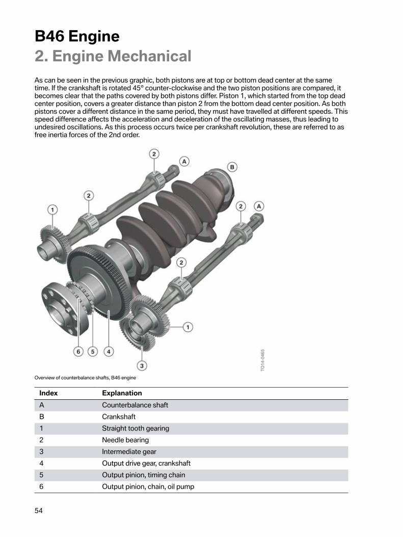
Overview�of�counterbalance�shafts,�B46�engine
Index ExplanationA Counterbalance�shaftB Crankshaft1 Straight�tooth�gearing2 Needle�bearing3 Intermediate�gear4 Output�drive�gear,�crankshaft5 Output�pinion,�timing�chain6 Output�pinion,�chain,�oil�pump
B46�Engine2.�Engine�Mechanical
55
The�B46�engine�has�two�counterbalance�shafts�which�rotate�at�twice�the�speed�of�the�crankshaft.The�gears�of�the�counterbalance�shafts�have�48�teeth.�The�gear�of�the�crankshaft�has�96�teeth.
A�correct�setting�of�the�two�counterbalance�shafts�is�a�prerequisite�for�reduction�of�the�oscillations.Using�a�special�tool�the�counterbalance�shafts�can�be�secured�in�their�specified�installation�positionin�Service.
A�gear�between�the�crankshaft�and�the�counterbalance�shaft�effects�the�change�of�rotational�directionof�the�right�counterbalance�shaft.�In�the�new�condition,�the�tooth�flanks�of�the�idler�gear�have�a�specialcoating.�This�coating�helps�adjust�the�tooth�backlash�between�the�counterbalance�shaft�and�thecrankshaft�during�installation�in�Service.�An�incorrectly�adjusted�tooth�backlash�can�lead�to�runningnoises�of�the�gears�when�the�engine�is�running.
A�newly�coated�idler�gear�must�be�installed�for�setting�the�counterbalance�shafts.The�repair�instructions�must�be�followed.
2.2.6.�Torsional�vibration�damperA�torsional�vibration�damper�is�used�on�the�belt�drive�of�B46�engine.�The�torsional�vibration�damperassumes�the�following�tasks:
• Reduction�of�the�torsional�oscillations�of�the�crankshaft.• Reduction�of�the�rotational�deformity�of�the�supporting�components.
B46�Engine2.�Engine�Mechanical
56
Variant�of�a�torsional�vibration�damper,�B46�engine
Index Explanation1 Belt�pulley2 Plain�bearing3 Belt�pulley�rubber�isolation�element4 Uncoupled�belt�pulley�hub5 Pressure�hub6 Vibration�damper�hub7 Vibration�damper�rubber�part8 Flywheel
B46�Engine2.�Engine�Mechanical
57
Vibration�damper
The�vibration�damper�comprises�a�hub,�a�rubber�element,�which�acts�as�a�spring,�and�a�flywheel,�whichserves�as�weight.�The�rotary�oscillations�of�the�crankshaft�are�reduced�by�the�combined�action�ofthe�spring�and�mass�element.�This�reduces�the�load�of�the�crankshaft�and�the�noises�emitted�by�theengine.
Uncoupled�belt�pulley
The�uncoupled�belt�pulley�is�important�for�smooth�low-wear�drive�of�supporting�components.�Thebelt�pulley�is�uncoupled�from�the�hub�by�the�rubber�isolation�element.�The�rubber�isolation�elementpermits�greater�rotation,�and�reduces�the�remaining�rotational�imbalance�and�thereby�the�load�on�thedrive�belt.�The�belt�pulley�is�supported�by�the�plain�bearing.
To�avoid�damage�to�the�torsional�vibration�damper,�the�engine�must�not�be�operatedwithout�drive�belts.
2.2.7.�Chain�drive
Features:
• Chain�drive�at�the�side�of�the�engine�emitting�the�forces.• Two-part�chain�drive�for�drive�of�camshafts,�synergy�parts�for�the�diesel�engines.• Simple�sleeve-type�chains.• Electric�motor�of�the�combined�oil-vacuum�pump�via�a�separate�chain.• Plastic�tensioning�rails�and�guide�rails.• Hydraulic�chain�tensioner�with�spring�preload.
B46�Engine2.�Engine�Mechanical
58
Chain�drive,�Bx8�engines
Index Explanation1 Upper�timing�chain2 VANOS�with�intake�camshaft�sprocket3 Upper�guide�rail4 Top�tensioning�rail5 Lower�timing�chain6 Camshaft�sprocket,�intermediate�shaft7 Bottom�tensioning�rail8 Lower�guide�rail9 Crankshaft10 Chain�oil-vacuum�pump11 Oil-vacuum�pump�camshaft�sprocket12 Lower�chain�tensioner13 Upper�chain�tensioner14 VANOS�with�exhaust�camshaft�sprocket
B46�Engine2.�Engine�Mechanical
59
The�chain�drive�is�on�the�transmission�side.�The�inertia�of�the�transmission�at�this�engine�endsignificantly�reduces�the�rotary�oscillations�and�also�therefore�the�loads�acting�on�the�chain�drive.
The�B46�engine�is�equipped�with�a�two-part�chain�drive.�With�this�arrangement,�the�bottom�timingchain�drives�the�camshaft�sprocket�of�the�intermediate�shaft.�The�drive�torque�is�simply�diverted�to�thetop�timing�chain�via�the�intermediate�shaft.
Sufficient�lubrication�of�the�bottom�timing�chain�is�ensured�by�the�oil�mist�in�the�crankcase�and�theengine�oil�that�drips�off.
The�combined�oil-vacuum�pump�is�also�driven�by�the�crankshaft�via�a�separate�drive�chain.
The�screw�connection�of�the�oil�and�vacuum�pump�camshaft�sprocket�has�a�left-hand�thread.
Lubrication�of�top�chain�drive
Lubrication�of�top�chain�drive,�B46�engine
B46�Engine2.�Engine�Mechanical
60
Index Explanation1 Upper�guide�rail2 Top�tensioning�rail3 Upper�timing�chain4 Top�chain�tensioner�with�oil�spray�nozzle5 Spray�pattern
The�timing�chain�is�always�tensioned�on�the�unloaded�side.�This�is�performed�by�a�tensioning�rail�onwhich�a�chain�tensioner�acts.�The�upper�timing�chain�is�lubricated�by�an�oil�spray�nozzle�in�the�topchain�tensioner.�There�is�an�opening�in�the�tensioning�rail�to�ensure�that�oil�reaches�the�top�timingchain.
2.3.�Valve�gear
2.3.1.�VariantsTwo�different�technologies�are�used�in�the�area�of�the�valve�gear.
Valve�gear,�B38�B46�engine.
Index ExplanationA Double�VANOSB Valvetronic
The�following�table�provides�an�overview�of�the�technology�used�in�the�B46�engine:
Engine Double�VANOS ValvetronicB46A20M0 Yes Yes
B46�Engine2.�Engine�Mechanical
61
2.3.2.�VANOSThe�valve�overlap�times�have�a�significant�impact�on�the�characteristics�of�the�engine.�An�engine�withsmaller�valve�overlap�therefore�tends�to�have�a�high�maximum�torque�at�low�engine�speeds�but�themaximum�power�which�can�be�achieved�at�high�engine�speeds�is�low.�The�maximum�power�achievedwith�a�large�valve�overlap�on�the�other�hand�is�higher,�but�this�is�at�the�expense�of�the�torque�at�lowengine�speeds.
The�VANOS�provides�a�solution.�It�makes�a�high�torque�possible�in�the�low�and�medium�engine�speedrange�and�a�high�maximum�power�in�the�higher�engine�speed�ranges.�A�further�benefit�of�the�VANOSis�the�option�of�internal�EGR.�This�reduces�the�emission�of�harmful�nitrogen�oxides�NOx,�particularly�inthe�partial�load�range.�The�following�is�also�achieved:
• Faster�heating�up�of�catalytic�converter.• Lower�pollutant�emissions�during�cold�start.• Reduction�in�consumption.
Double�VANOS,�Bx8�engine
Index ExplanationA Intake�camshaftB Exhaust�camshaft1 Increment�wheel,�intake�camshaft2 Increment�wheel,�exhaust�camshaft3 Triple�cam�for�high�pressure�pump�drive�system
B46�Engine2.�Engine�Mechanical
62
Index Explanation4 Exhaust�camshaft�sprocket5 VANOS�unit,�exhaust�side6 VANOS�solenoid�valve�actuator,�exhaust7 VANOS�solenoid�valve�actuator,�intake8 VANOS�unit,�intake�side9 Intake�camshaft�sprocket
Reason�for�using�the�double�VANOS
The�advantages�of�a�Valvetronic�are�lower�charge�cycle�losses�and�therefore�potential�for�reducing�fuelconsumption�by�adopting�an�appropriate�driving�style.�However,�in�contrast�to�throttle�valve-controlledsystems,�Valvetronic�cannot�reduce�charge-cycle�losses�in�the�full�load�range.
VANOS�unit
With�older�VANOS�systems,�such�as�that�used�in�the�N55�engine,�the�VANOS�units�were�controlled�byseparate�VANOS�solenoid�valves�integrated�into�oil�ducts�in�the�cylinder�head.
The�oil�ducts�in�the�cylinder�head�are�reduced�and�the�adjustment�speed�is�increased�by�using�aVANOS�solenoid�valve�unit�and�a�mechanical�VANOS�central�valve,�which�is�located�inside�the�VANOSunit.
B46�Engine2.�Engine�Mechanical
63
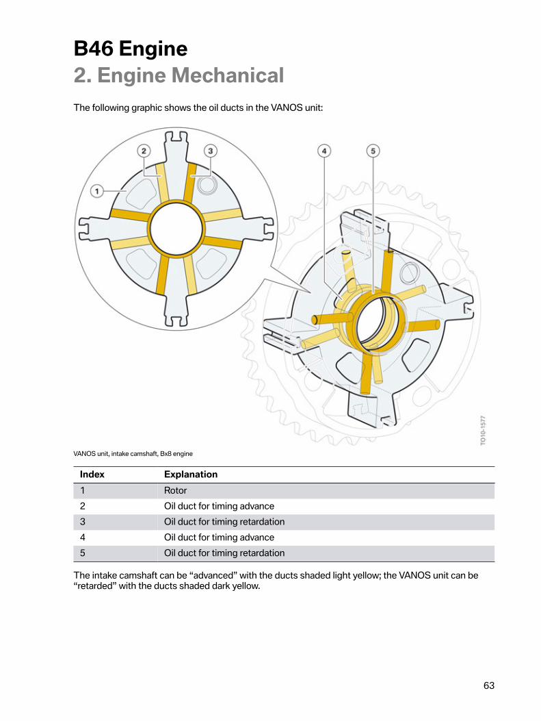
The�following�graphic�shows�the�oil�ducts�in�the�VANOS�unit:
VANOS�unit,�intake�camshaft,�Bx8�engine
Index Explanation1 Rotor2 Oil�duct�for�timing�advance3 Oil�duct�for�timing�retardation4 Oil�duct�for�timing�advance5 Oil�duct�for�timing�retardation
The�intake�camshaft�can�be�“advanced”�with�the�ducts�shaded�light�yellow;�the�VANOS�unit�can�be“retarded”�with�the�ducts�shaded�dark�yellow.
B46�Engine2.�Engine�Mechanical
64
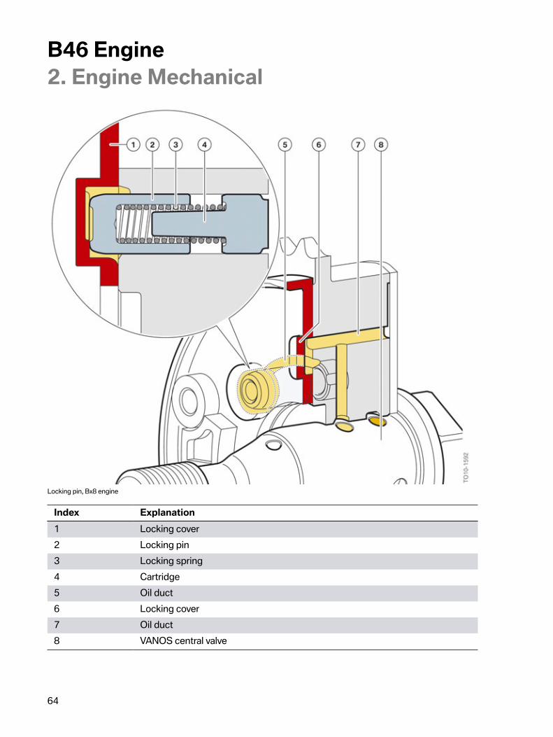
Locking�pin,�Bx8�engine
Index Explanation1 Locking�cover2 Locking�pin3 Locking�spring4 Cartridge5 Oil�duct6 Locking�cover7 Oil�duct8 VANOS�central�valve
B46�Engine2.�Engine�Mechanical
65
The�locking�pin�ensures�that�the�VANOS�unit�adopts�a�clear,�locked�position�in�the�depressurizedstate.�The�locking�spring�ensures�the�unit�is�locked�by�continuously�pushing�the�locking�pin�into�thelocked�position�when�the�actuator�is�de-energized.�The�VANOS�unit�is�blocked�in�this�condition.�Thetiming�can�be�adjusted�in�this�way.�This�is�important�when�the�engine�is�started�to�ensure�exact�timing.The�oil�pressure�which�is�present�for�timing�advance�simultaneously�unlocks�the�locking�pin�via�oilducts�in�the�VANOS�unit.�If�the�camshaft�is�to�be�“advanced”,�the�locking�pin�is�then�forced�by�theapplied�oil�pressure�against�the�locking�spring�towards�the�cartridge�and�the�locking�cover�is�releasedfor�VANOS�adjustment.
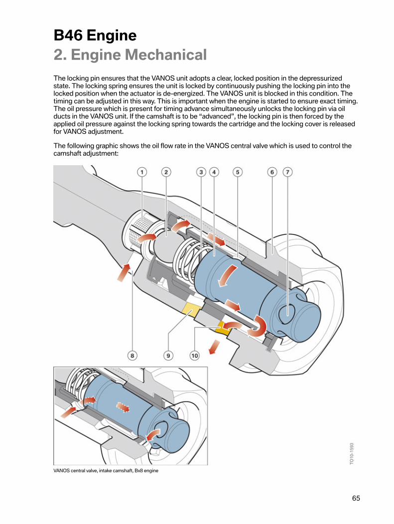
The�following�graphic�shows�the�oil�flow�rate�in�the�VANOS�central�valve�which�is�used�to�control�thecamshaft�adjustment:
VANOS�central�valve,�intake�camshaft,�Bx8�engine
B46�Engine2.�Engine�Mechanical
66
Index Explanation1 Filter2 Ball3 Spring4 Piston5 Sleeve6 Housing7 Opening�in�plunger8 Oil�supply�from�main�oil�duct9 Bore�to�oil�duct�in�VANOS�(timing�advance)10 Bore�to�oil�duct�in�VANOS�(timing�retardation)
The�VANOS�unit�is�secured�to�the�camshaft�by�the�VANOS�central�valve.�The�oil�flow�into�the�VANOSunit�is�simultaneously�controlled�by�this�VANOS�central�valve.�The�system�is�actuated�by�a�solenoidactuator�with�its�own�piston�that�pushes�on�and�displaces�the�piston�of�the�VANOS�central�valve.The�oil�flow�is�controlled�by�means�of�the�plunger.
The�previous�graphic�shows�the�de-energized�VANOS�central�valve.�The�locking�pin�blocks�theVANOS�unit.
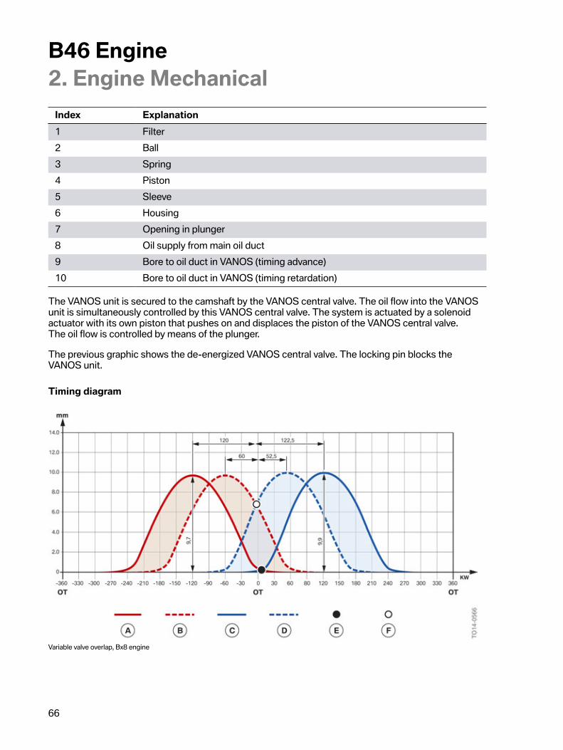
Timing�diagram
Variable�valve�overlap,�Bx8�engine
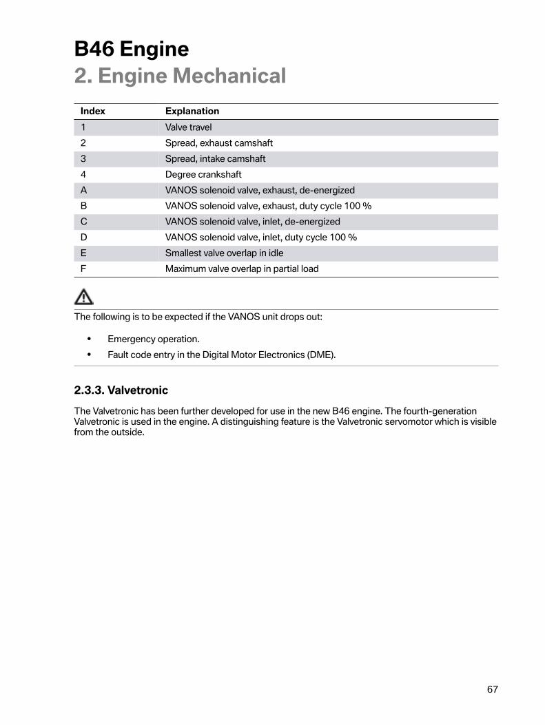
B46�Engine2.�Engine�Mechanical
67
Index Explanation1 Valve�travel2 Spread,�exhaust�camshaft3 Spread,�intake�camshaft4 Degree�crankshaftA VANOS�solenoid�valve,�exhaust,�de-energizedB VANOS�solenoid�valve,�exhaust,�duty�cycle�100 %C VANOS�solenoid�valve,�inlet,�de-energizedD VANOS�solenoid�valve,�inlet,�duty�cycle�100 %E Smallest�valve�overlap�in�idleF Maximum�valve�overlap�in�partial�load
The�following�is�to�be�expected�if�the�VANOS�unit�drops�out:
• Emergency�operation.• Fault�code�entry�in�the�Digital�Motor�Electronics�(DME).
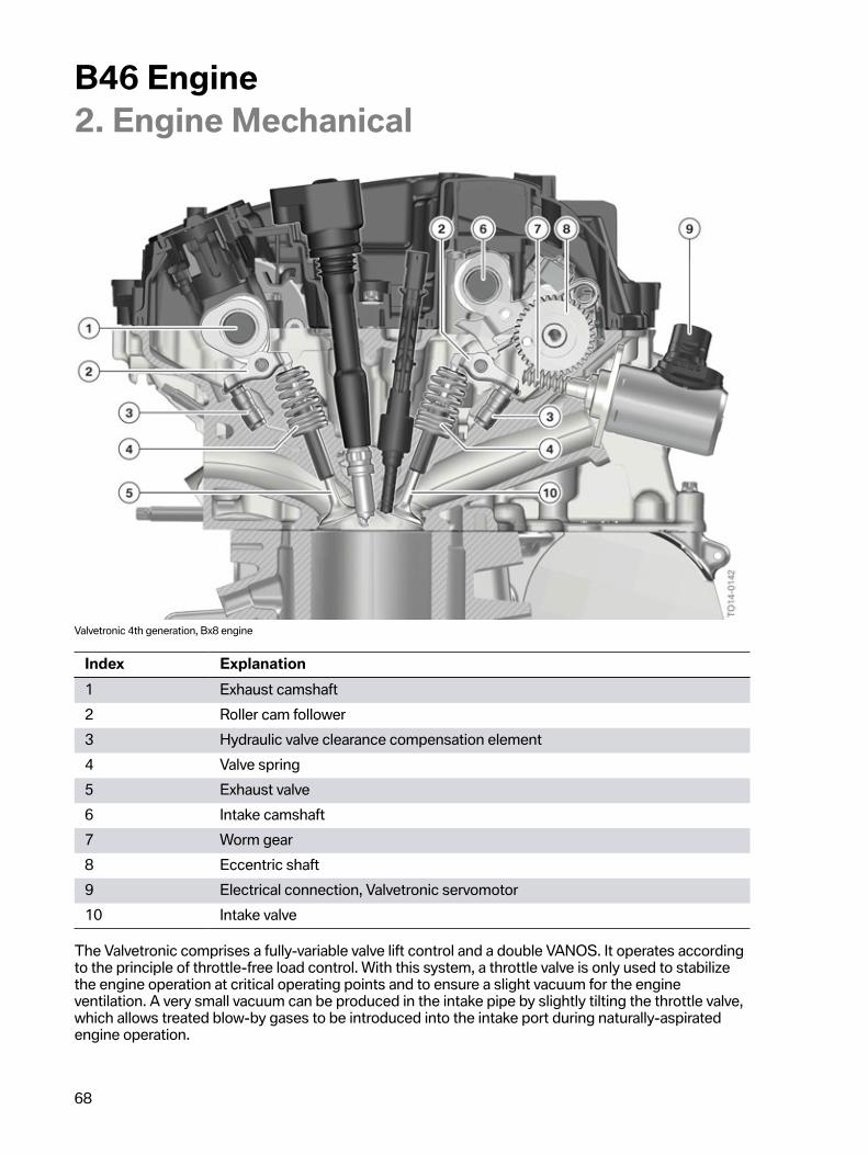
2.3.3.�ValvetronicThe�Valvetronic�has�been�further�developed�for�use�in�the�new�B46�engine.�The�fourth-generationValvetronic�is�used�in�the�engine.�A�distinguishing�feature�is�the�Valvetronic�servomotor�which�is�visiblefrom�the�outside.
B46�Engine2.�Engine�Mechanical
68
Valvetronic�4th�generation,�Bx8�engine
Index Explanation1 Exhaust�camshaft2 Roller�cam�follower3 Hydraulic�valve�clearance�compensation�element4 Valve�spring5 Exhaust�valve6 Intake�camshaft7 Worm�gear8 Eccentric�shaft9 Electrical�connection,�Valvetronic�servomotor10 Intake�valve
The�Valvetronic�comprises�a�fully-variable�valve�lift�control�and�a�double�VANOS.�It�operates�accordingto�the�principle�of�throttle-free�load�control.�With�this�system,�a�throttle�valve�is�only�used�to�stabilizethe�engine�operation�at�critical�operating�points�and�to�ensure�a�slight�vacuum�for�the�engineventilation.�A�very�small�vacuum�can�be�produced�in�the�intake�pipe�by�slightly�tilting�the�throttle�valve,which�allows�treated�blow-by�gases�to�be�introduced�into�the�intake�port�during�naturally-aspiratedengine�operation.
B46�Engine2.�Engine�Mechanical
69
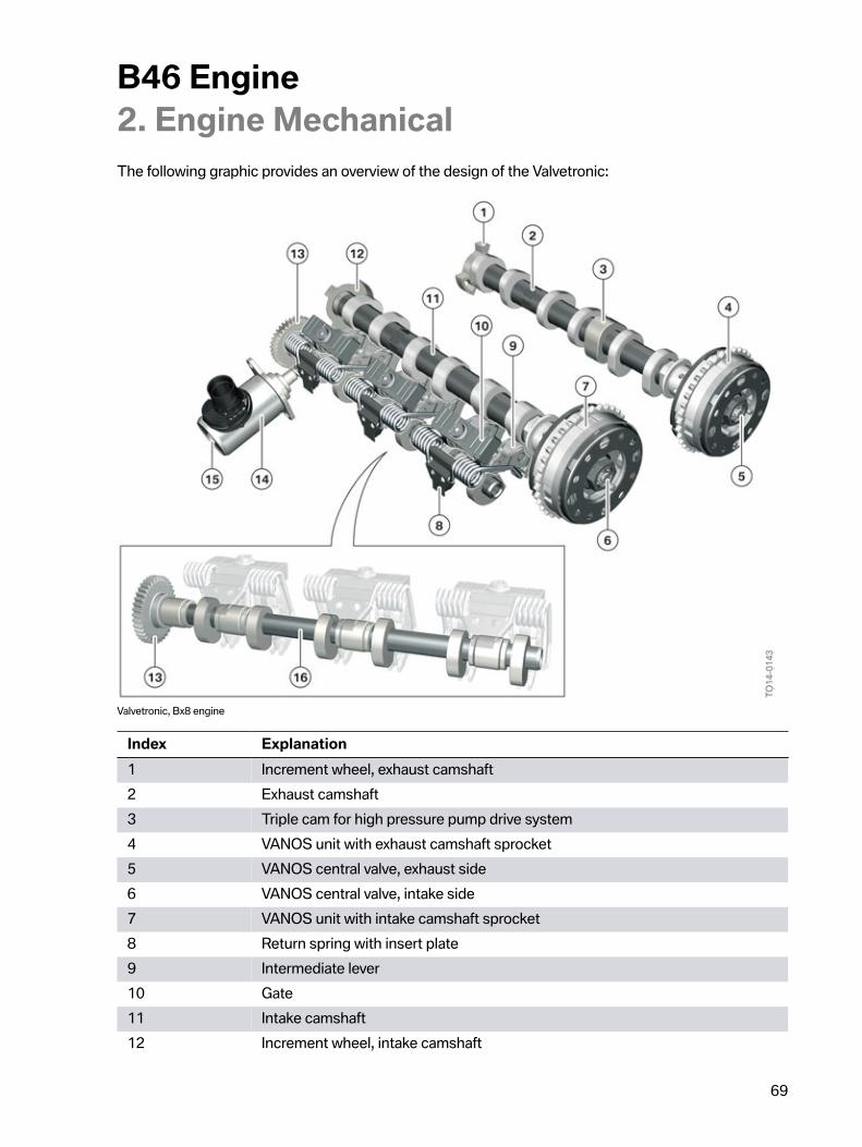
The�following�graphic�provides�an�overview�of�the�design�of�the�Valvetronic:
Valvetronic,�Bx8�engine
Index Explanation1 Increment�wheel,�exhaust�camshaft2 Exhaust�camshaft3 Triple�cam�for�high�pressure�pump�drive�system4 VANOS�unit�with�exhaust�camshaft�sprocket5 VANOS�central�valve,�exhaust�side6 VANOS�central�valve,�intake�side7 VANOS�unit�with�intake�camshaft�sprocket8 Return�spring�with�insert�plate9 Intermediate�lever10 Gate11 Intake�camshaft12 Increment�wheel,�intake�camshaft
B46�Engine2.�Engine�Mechanical
70
Index Explanation13 Drive�pinion,�eccentric�shaft14 Valvetronic�servomotor15 Hexagon�socket�(Inbus)16 Eccentric�shaft
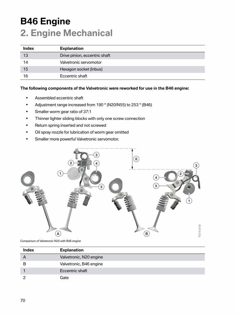
The�following�components�of�the�Valvetronic�were�reworked�for�use�in�the�B46�engine:
• Assembled�eccentric�shaft• Adjustment�range�increased�from�190�°�(N20/N55)�to�253�°�(B46)• Smaller�worm�gear�ratio�of�37:1• Thinner�lighter�sliding�blocks�with�only�one�screw�connection• Return�spring�inserted�and�not�screwed• Oil�spray�nozzle�for�lubrication�of�worm�gear�omitted• Smaller�more�powerful�Valvetronic�servomotor.
Comparison�of�Valvetronic�N20�with�B46�engine
Index ExplanationA Valvetronic,�N20�engineB Valvetronic,�B46�engine1 Eccentric�shaft2 Gate
B46�Engine2.�Engine�Mechanical
71
Index Explanation3 Return�spring4 Camshaft5 Intermediate�lever6 Height�of�installation�space
By�reworking�the�Valvetronic,�it�has,�most�importantly,�been�possible�to�significantly�reduce�theinstallation�space.�A�considerable�height�advantage�has�been�gained�by�swapping�round�the�intakecamshaft�and�the�eccentric�shaft.�The�new�position�of�the�intermediate�lever�and�gate�simplifies�theapplication�of�force�in�the�cylinder�head.�The�gate�is�therefore�only�attached�to�the�bearing�supportwith�one�screw�and�is�positioned�via�two�precise�contact�surfaces�in�the�cylinder�head.�The�returnspring�for�the�intermediate�lever�between�the�cylinder�head�and�bearing�position�is�self-supportingand�does�not�require�its�own�attachment�point.�The�eccentric�shaft�is,�as�is�already�the�case�with�thecamshaft,�an�"assembled"�design.
B46�Engine2.�Engine�Mechanical
72
Lubricating�oil�supply�to�the�Valvetronic�worm�gear
Lubricating�oil�supply�to�the�Valvetronic�worm�gear,�B46�engine
Index Explanation1 Cylinder�head2 Drive�pinion�of�the�eccentric�shaft3 Worm�gear�of�Valvetronic�servomotor4 Valvetronic�servomotor5 Outlet�bore�hole6 First�bearing�position�of�eccentric�shaft7 Inlet�bore�hole8 Oil�chamber
B46�Engine2.�Engine�Mechanical
73
Due�to�the�fast�adjustment�speeds�of�the�eccentric�shaft�of�less�than�300�milliseconds�from�minimumto�maximum�stroke�and�the�wide�adjustment�range�from�0.2�millimeters�(minimum)�to�9.9�millimeters(maximum)�valve�lift�with�a�small�transmission�ratio,�sufficient�lubrication�between�the�worm�gear�ofthe�Valvetronic�servomotor�and�drive�pinion�of�the�eccentric�shaft�must�be�ensured.�The�lubricating�oilreaches�the�oil�chamber�via�an�inlet�bore�hole�at�the�first�bearing�position�of�the�eccentric�shaft.�Here,the�oil�volume�rises�to�the�lower�edge�of�the�outlet�bore�hole.�The�excess�oil�flows�back�to�the�oil�circuitvia�the�outlet�bore�hole.�The�gearing�of�the�worm�gear�is�now�supported�in�the�oil�bath�and�is�thereforelubricated�at�all�times.
Information�on�disassembly�and�installation�work
As�numerous�changes�have�been�made,�a�new�special�tool�is�used�to�remove�the�return�springs.
The�hexagon�socket�on�the�Valvetronic�servomotor�is�for�manual�adjustment�of�the�worm�gear.�Thisis�necessary�if�the�Valvetronic�servomotor�needs�to�be�removed,�for�example.�To�avoid�damage�to�theworm�gear,�it�must�be�greased�prior�to�start-up�using�a�special�lubricant�(Longtime�PD�part�number:83�19�2�160�340).�The�Valvetronic�in�the�Digital�Motor�Electronics�(DME)�can�be�taught-in�using�theteach-in�routine�in�ISTA.�During�this�process,�the�limit�positions�of�the�system�are�determined�onceagain�and�stored�in�the�Digital�Motor�Electronics�(DME).�The�precise�procedure�for�removing�theValvetronic�is�described�in�the�current�repair�instructions.
B46�Engine2.�Engine�Mechanical
74
2.4.�Belt�drive
Belt�drive,�transverse-mounted�B46�engine
Index ExplanationA With�air�conditioning�compressor1 Ribbed V-belt2 Alternator3 Coolant�pump4 Air�conditioning�compressor5 Torsional�vibration�damper6 Deflecting�element7 Tensioning�pulley
The�length�of�the�drive�belt�changes�due�to�thermal�expansion�and�ageing.�So�the�drive�belt�cantransmit�the�required�torque,�it�must�be�continuously�in�contact�with�the�belt�pulley�at�a�definedpressure.�To�this�end�the�belt�tension�is�exerted�by�an�automatic�tensioning�pulley�which�compensatesfor�belt�elongation�over�the�full�service�life.
A�standard�belt�with�6�ribs�is�used.
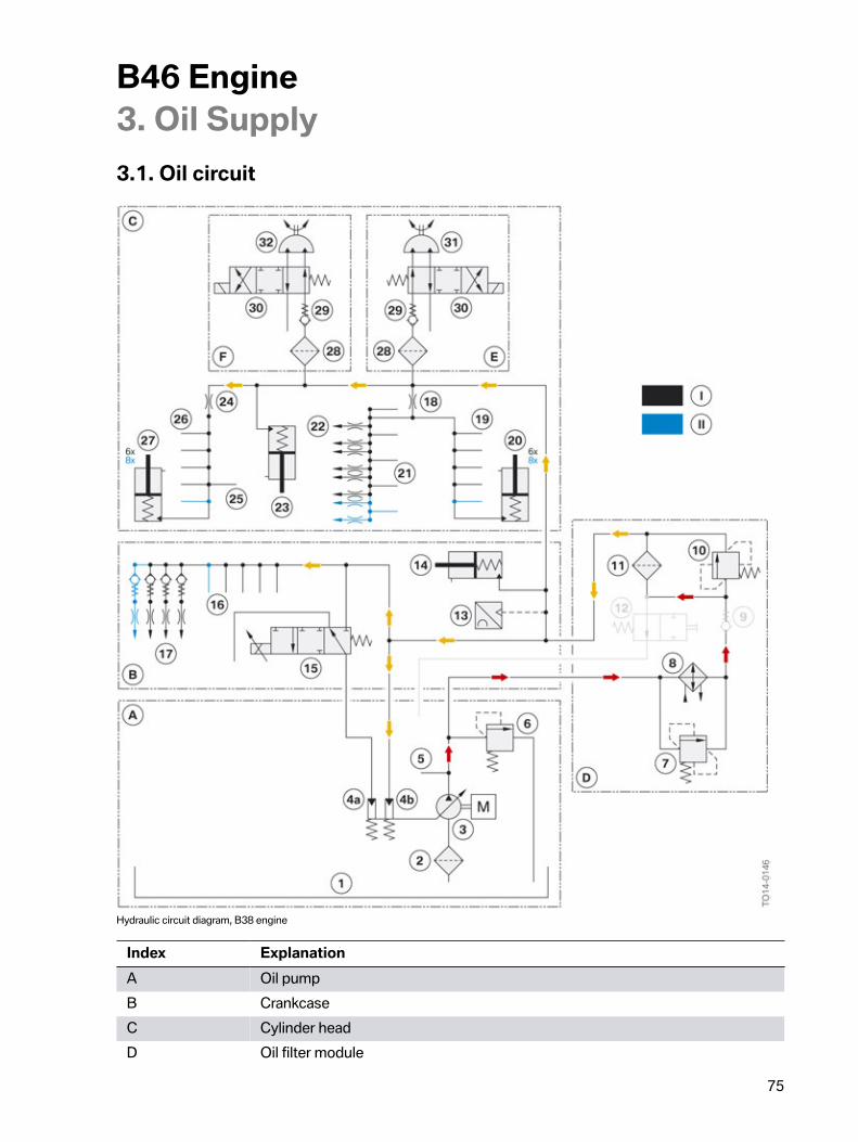
B46�Engine3.�Oil�Supply
75
3.1.�Oil�circuit
Hydraulic�circuit�diagram,�B38�engine
Index ExplanationA Oil�pumpB CrankcaseC Cylinder�headD Oil�filter�module
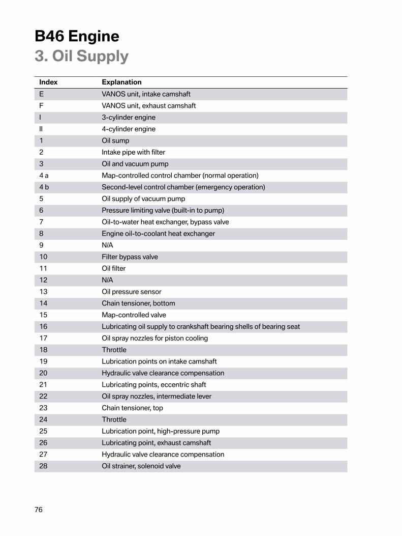
B46�Engine3.�Oil�Supply
76
Index ExplanationE VANOS�unit,�intake�camshaftF VANOS�unit,�exhaust�camshaftI 3-cylinder�engineII 4-cylinder�engine1 Oil�sump2 Intake�pipe�with�filter3 Oil�and�vacuum�pump4�a Map-controlled�control�chamber�(normal�operation)4�b Second-level�control�chamber�(emergency�operation)5 Oil�supply�of�vacuum�pump6 Pressure�limiting�valve�(built-in�to�pump)7 Oil-to-water�heat�exchanger,�bypass�valve8 Engine�oil-to-coolant�heat�exchanger9 N/A10 Filter�bypass�valve11 Oil�filter12 N/A13 Oil�pressure�sensor14 Chain�tensioner,�bottom15 Map-controlled�valve16 Lubricating�oil�supply�to�crankshaft�bearing�shells�of�bearing�seat17 Oil�spray�nozzles�for�piston�cooling18 Throttle19 Lubrication�points�on�intake�camshaft20 Hydraulic�valve�clearance�compensation21 Lubricating�points,�eccentric�shaft22 Oil�spray�nozzles,�intermediate�lever23 Chain�tensioner,�top24 Throttle25 Lubrication�point,�high-pressure�pump26 Lubricating�point,�exhaust�camshaft27 Hydraulic�valve�clearance�compensation28 Oil�strainer,�solenoid�valve
B46�Engine3.�Oil�Supply
77
Index Explanation29 Non-return�valve30 Solenoid�valve31 VANOS�swivel�rotor�(intake�camshaft)32 VANOS�swivel�rotor�(exhaust�camshaft)
With�force-fed�circulation�lubrication�the�oil�is�drawn�out�of�the�oil�sump�by�the�oil�pump�throughan�intake�pipe�and�forwarded�into�the�circuit.�The�oil�passes�through�the�engine�oil�cooler�with�anintegrated�full-flow�oil�filter�and�from�there�into�the�main�oil�duct,�which�runs�in�the�engine�block�parallelto�the�crankshaft.�Branch�ducts�lead�to�the�crankshaft�main�bearings.�There�are�bore�holes�betweenthe�main�bearings�of�the�crankshaft�and�the�connecting�rod�bearing�journal�which�admit�the�oil�to�thelubricating�points�of�the�connecting�rod�bearing.
Some�of�the�oil�is�diverted�from�the�main�oil�duct�and�directed�to�the�cylinder�head�to�the�relevantlubricating�points�and�adjustment�units.�When�the�engine�oil�flows�through�the�consumers,�it�eitherreturns�to�the�oil�sump�via�the�return�ducts�or�it�drips�back�freely.
3.2.�Map�control
System�overview�of�map-controlled�oil�supply�of�Bx8�engine
B46�Engine3.�Oil�Supply
78
Index ExplanationA Oil�pressure�sensor�signalB Activation�of�map-controlled�control�valve1 Main�oil�duct�to�the�oil�pressure�sensor2 Oil�pressure�sensor3 Digital�Motor�Electronics�(DME)4 Oil�pump5 Oil�duct�to�map-controlled�control�chamber�of�oil�pump6 Map�control�valve
The�B46�engine�is�equipped�with�the�familiar�map-controlled�oil�pump�which�is�already�used.The�actual�oil�pressure�is�recorded�via�an�oil�pressure�sensor�and�forwarded�to�the�Digital�MotorElectronics�(DME).�The�Digital�Motor�Electronics�performs�a�target/actual�comparison�based�on�thestored�characteristic�maps.�The�map-controlled�control�valve�is�activated�by�means�of�a�pulse-widthmodulated�signal�until�the�nominal�pressure�stored�in�the�characteristic�map�has�been�reached.�Duringthis�process,�the�delivery�rate�of�the�oil�pump�varies�according�to�the�oil�pressure�in�the�oil�duct�to�themap-controlled�control�chamber.
3.3.�Oil�pumpThe�oil�pump�plays�a�central�role�in�modern�combustion�engines.�Due�to�the�high�power�and�enormoustorque�which�is�present�even�at�low�engine�speeds,�it�is�necessary�to�ensure�a�reliable�oil�supply.�Thisis�necessary�on�account�of�the�high�component�temperatures�and�heavily�loaded�bearings.�To�achievelow�fuel�consumption,�the�delivery�rate�of�the�oil�pump�must�be�adapted�to�the�requirements.
The�oil�pump�is�driven�by�the�crankshaft�via�a�chain.
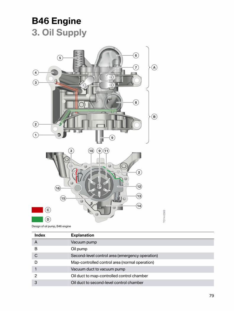
B46�Engine3.�Oil�Supply
79
Design�of�oil�pump,�B46�engine
Index ExplanationA Vacuum�pumpB Oil�pumpC Second-level�control�area�(emergency�operation)D Map-controlled�control�area�(normal�operation)1 Vacuum�duct�to�vacuum�pump2 Oil�duct�to�map-controlled�control�chamber3 Oil�duct�to�second-level�control�chamber
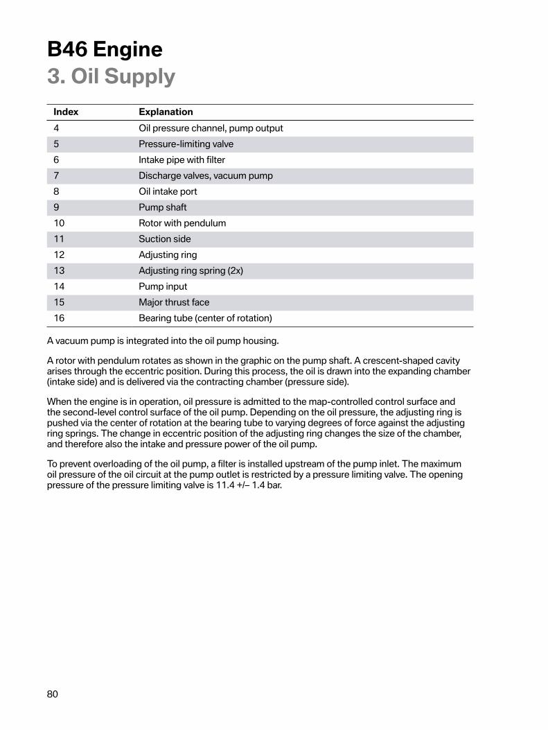
B46�Engine3.�Oil�Supply
80
Index Explanation4 Oil�pressure�channel,�pump�output5 Pressure-limiting�valve6 Intake�pipe�with�filter7 Discharge�valves,�vacuum�pump8 Oil�intake�port9 Pump�shaft10 Rotor�with�pendulum11 Suction�side12 Adjusting�ring13 Adjusting�ring�spring�(2x)14 Pump�input15 Major�thrust�face16 Bearing�tube�(center�of�rotation)
A�vacuum�pump�is�integrated�into�the�oil�pump�housing.
A�rotor�with�pendulum�rotates�as�shown�in�the�graphic�on�the�pump�shaft.�A�crescent-shaped�cavityarises�through�the�eccentric�position.�During�this�process,�the�oil�is�drawn�into�the�expanding�chamber(intake�side)�and�is�delivered�via�the�contracting�chamber�(pressure�side).
When�the�engine�is�in�operation,�oil�pressure�is�admitted�to�the�map-controlled�control�surface�andthe�second-level�control�surface�of�the�oil�pump.�Depending�on�the�oil�pressure,�the�adjusting�ring�ispushed�via�the�center�of�rotation�at�the�bearing�tube�to�varying�degrees�of�force�against�the�adjustingring�springs.�The�change�in�eccentric�position�of�the�adjusting�ring�changes�the�size�of�the�chamber,and�therefore�also�the�intake�and�pressure�power�of�the�oil�pump.
To�prevent�overloading�of�the�oil�pump,�a�filter�is�installed�upstream�of�the�pump�inlet.�The�maximumoil�pressure�of�the�oil�circuit�at�the�pump�outlet�is�restricted�by�a�pressure�limiting�valve.�The�openingpressure�of�the�pressure�limiting�valve�is�11.4�+/–�1.4�bar.
B46�Engine3.�Oil�Supply
81
3.3.1.�Map�control�valveThe�map-controlled�control�valve�is�a�proportional�valve�which�can�control�the�oil�pressure�steplessly.
Map-controlled�control�valve,�B46�engine
Index ExplanationA Voltage�curve,�maximum�delivery�rateB Voltage�curve,�minimum�delivery�rateC Voltage�curve,�50 %�delivery�rate1 Oil�duct�from�the�oil�filter2 Oil�duct�to�oil�pump3 Sealing�ring4 Solenoid�coil5 Electrical�connection6 Valve�spool7 Filter
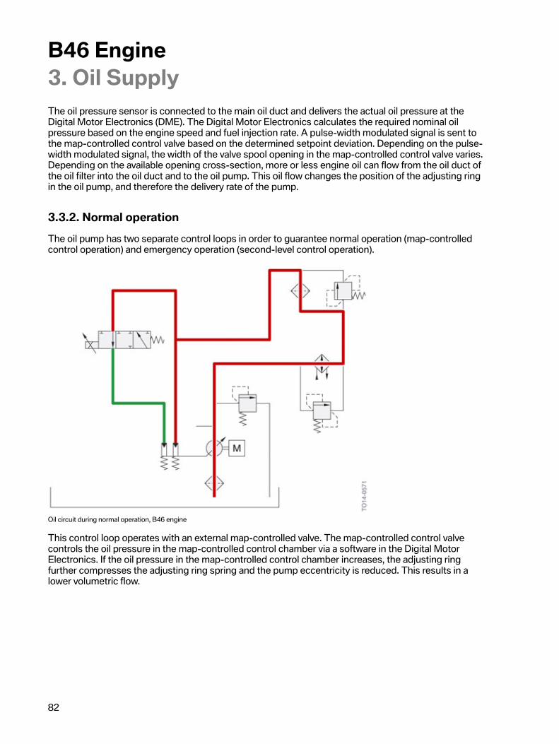
B46�Engine3.�Oil�Supply
82
The�oil�pressure�sensor�is�connected�to�the�main�oil�duct�and�delivers�the�actual�oil�pressure�at�theDigital�Motor�Electronics�(DME).�The�Digital�Motor�Electronics�calculates�the�required�nominal�oilpressure�based�on�the�engine�speed�and�fuel�injection�rate.�A�pulse-width�modulated�signal�is�sent�tothe�map-controlled�control�valve�based�on�the�determined�setpoint�deviation.�Depending�on�the�pulse-width�modulated�signal,�the�width�of�the�valve�spool�opening�in�the�map-controlled�control�valve�varies.Depending�on�the�available�opening�cross-section,�more�or�less�engine�oil�can�flow�from�the�oil�duct�ofthe�oil�filter�into�the�oil�duct�and�to�the�oil�pump.�This�oil�flow�changes�the�position�of�the�adjusting�ringin�the�oil�pump,�and�therefore�the�delivery�rate�of�the�pump.
3.3.2.�Normal�operationThe�oil�pump�has�two�separate�control�loops�in�order�to�guarantee�normal�operation�(map-controlledcontrol�operation)�and�emergency�operation�(second-level�control�operation).
Oil�circuit�during�normal�operation,�B46�engine
This�control�loop�operates�with�an�external�map-controlled�valve.�The�map-controlled�control�valvecontrols�the�oil�pressure�in�the�map-controlled�control�chamber�via�a�software�in�the�Digital�MotorElectronics.�If�the�oil�pressure�in�the�map-controlled�control�chamber�increases,�the�adjusting�ringfurther�compresses�the�adjusting�ring�spring�and�the�pump�eccentricity�is�reduced.�This�results�in�alower�volumetric�flow.
B46�Engine3.�Oil�Supply
83
3.3.3.�Emergency�operation
Oil�circuit�during�emergency�operation,�B46�engine
During�emergency�operation,�the�system�operates�without�the�map�control�by�the�Digital�MotorElectronics.�The�map-controlled�control�valve�is�de-energized�in�this�operating�condition�and�istherefore�closed.�The�purpose�of�the�emergency�operation�is�to�maintain�the�oil�pressure�in�the�oilpump�at�a�consistently�high�level.�The�oil�pressure�is�guided�directly�from�the�main�oil�duct�to�thesecond-level�control�chamber.�This�leads�to�an�adjustment�of�the�adjusting�ring�against�the�adjustingring�spring�and�thus�a�reduction�of�the�volumetric�flow.�As�it�contains�no�actuators,�intervention�in�thiscontrol�system�is�not�possible�and�it�also�cannot�be�switched�off.
B46�Engine3.�Oil�Supply
84
Operating�principle�of�oil�pump�control�system,�B46�engine
Index ExplanationA Normal�operationB Emergency�operation
3.4.�Suction�pipeThe�oil�pump�draws�oil�from�the�oil�sump�through�the�intake�pipe.�The�suction�pipe�is�positionedso�that�the�suction�opening�is�below�the�oil�level�under�all�operating�conditions.�The�intake�pipeincorporates�an�oil�strainer,�which�prevents�coarse�dirt�particles�from�getting�into�the�oil�pump.
Intake�pipe�in�B46�engine
The�intake�pipe�is�a�separate�component�which�is�screwed�on�to�the�oil�pump.
B46�Engine3.�Oil�Supply
85
3.5.�Pressure-limiting�valve
Pressure�limiting�valve�in�oil�circuit�in�B46�engine
Index ExplanationA Oil�pressure�<�11.4�+/–�1.4�barB Oil�pressure�>�11.4�+/–�1.4�barC Engine�oil�volumetric�flow1 Pressure�limiting�valve�closed2 Pressure�limiting�valve�open
The�pressure�limiting�valve�is�responsible�for�protecting�the�oil�pump�and�the�oil�circuit�againstoverloading.�This�valve�opens�at�an�oil�pressure�of�>�10�bar�and�directs�the�excess�engine�oil�back�tothe�oil�sump.�This�valve�is�used�if�necessary�when�starting�the�engine�at�cold�ambient�temperatures(values�<�0�°C),�as�the�viscosity�of�the�engine�oil�is�very�high�here.
B46�Engine3.�Oil�Supply
86
3.6.�Oil�filter�module
Oil�filter�module
Index Explanation1 Engine�oil-to-coolant�heat�exchanger2 Oil�filter�housing3 Oil�filter�cover4 Hexagon�head�for�opening�the�oil�filter�cover5 Hexagon�head�for�opening�the�oil�drain�plug
Due�to�the�construction�space,�the�oil�filter�housing�is�suspended�in�the�transverse�mounting.The�inspection�is�carried�out�from�the�bottom�of�the�vehicle.�Using�an�oil�drain�plug�the�Serviceemployee�can�drain�the�engine�oil�from�the�oil�filter�module�before�opening�the�oil�filter�cover.
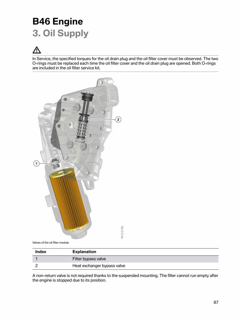
B46�Engine3.�Oil�Supply
87
In�Service,�the�specified�torques�for�the�oil�drain�plug�and�the�oil�filter�cover�must�be�observed.�The�twoO-rings�must�be�replaced�each�time�the�oil�filter�cover�and�the�oil�drain�plug�are�opened.�Both�O-ringsare�included�in�the�oil�filter�service�kit.
Valves�of�the�oil�filter�module
Index Explanation1 Filter�bypass�valve2 Heat�exchanger�bypass�valve
A�non-return�valve�is�not�required�thanks�to�the�suspended�mounting.�The�filter�cannot�run�empty�afterthe�engine�is�stopped�due�to�its�position.
B46�Engine3.�Oil�Supply
88
3.6.1.�Filter�bypass�valveWhen�a�filter�is�blocked,�the�filter�bypass�valve�ensures�that�engine�oil�reaches�the�lubrication�points�ofthe�engine.�It�opens�when�the�differential�pressure�upstream�and�downstream�of�the�oil�filter�is�2.5�bar±�0.3�bar.
3.6.2.�Heat�exchanger�bypass�valveThe�heat�exchanger�bypass�valve�has�the�same�function�as�the�filter�bypass�valve.�If,�on�account�of�ablocked�oil-to-water�heat�exchanger,�the�oil�pressure�rises,�the�heat�exchanger�bypass�valve�opens�atan�oil�pressure�of�2.5�bar�±�0.3�bar�and�the�lubricating�oil�can�flow�uncooled�to�the�lubrication�points.
To�ensure�the�engine�runs�perfectly,�only�engine�oils�approved�by�BMW�can�be�used.

B46�Engine4.�Cooling�System
89
In�order�to�protect�the�thermally�loaded�engine�components,�the�engine�oil�and�the�transmission�oilfrom�overheating,�they�are�cooled�using�coolant.�A�mechanical�coolant�pump�circulates�the�coolant�inthe�cooling�circuit.�The�heat�quantities�introduced�to�the�coolant�are�emitted�to�the�ambient�air�againusing�a�radiator.�An�electric�fan�assists�the�radiator�output.
The�coolant�in�the�B46�engine�is�mainly�circulated�via�a�mechanical�coolant�pump.�Several�engines�arealso�equipped�with�an�electrical�overrun�pump�which�maintains�a�trickle�of�coolant�to�the�bearing�seatcooling�system�of�the�exhaust�turbocharger.
The�following�graphics�provide�an�overview�of�the�different�cooling�circuits.
4.1.�Cooling�circuit,�B46�engine
Cooling�circuit,�B46�engine
Index Explanation1 Radiator2 Electric�fan3 Map�thermostat4 Coolant�pump5 Coolant�temperature�sensor6 Coolant-cooled�exhaust�turbocharger7 Engine�housing
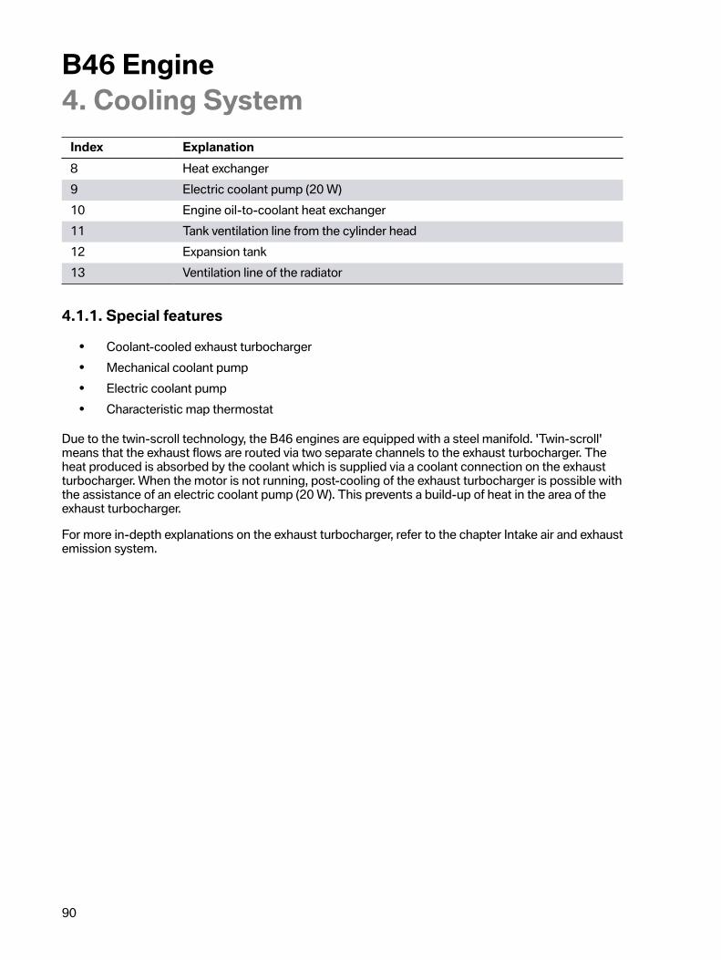
B46�Engine4.�Cooling�System
90
Index Explanation8 Heat�exchanger9 Electric�coolant�pump�(20 W)10 Engine�oil-to-coolant�heat�exchanger11 Tank�ventilation�line�from�the�cylinder�head12 Expansion�tank13 Ventilation�line�of�the�radiator
4.1.1.�Special�features• Coolant-cooled�exhaust�turbocharger• Mechanical�coolant�pump• Electric�coolant�pump• Characteristic�map�thermostat
Due�to�the�twin-scroll�technology,�the�B46�engines�are�equipped�with�a�steel�manifold.�'Twin-scroll'means�that�the�exhaust�flows�are�routed�via�two�separate�channels�to�the�exhaust�turbocharger.�Theheat�produced�is�absorbed�by�the�coolant�which�is�supplied�via�a�coolant�connection�on�the�exhaustturbocharger.�When�the�motor�is�not�running,�post-cooling�of�the�exhaust�turbocharger�is�possible�withthe�assistance�of�an�electric�coolant�pump�(20�W).�This�prevents�a�build-up�of�heat�in�the�area�of�theexhaust�turbocharger.
For�more�in-depth�explanations�on�the�exhaust�turbocharger,�refer�to�the�chapter�Intake�air�and�exhaustemission�system.
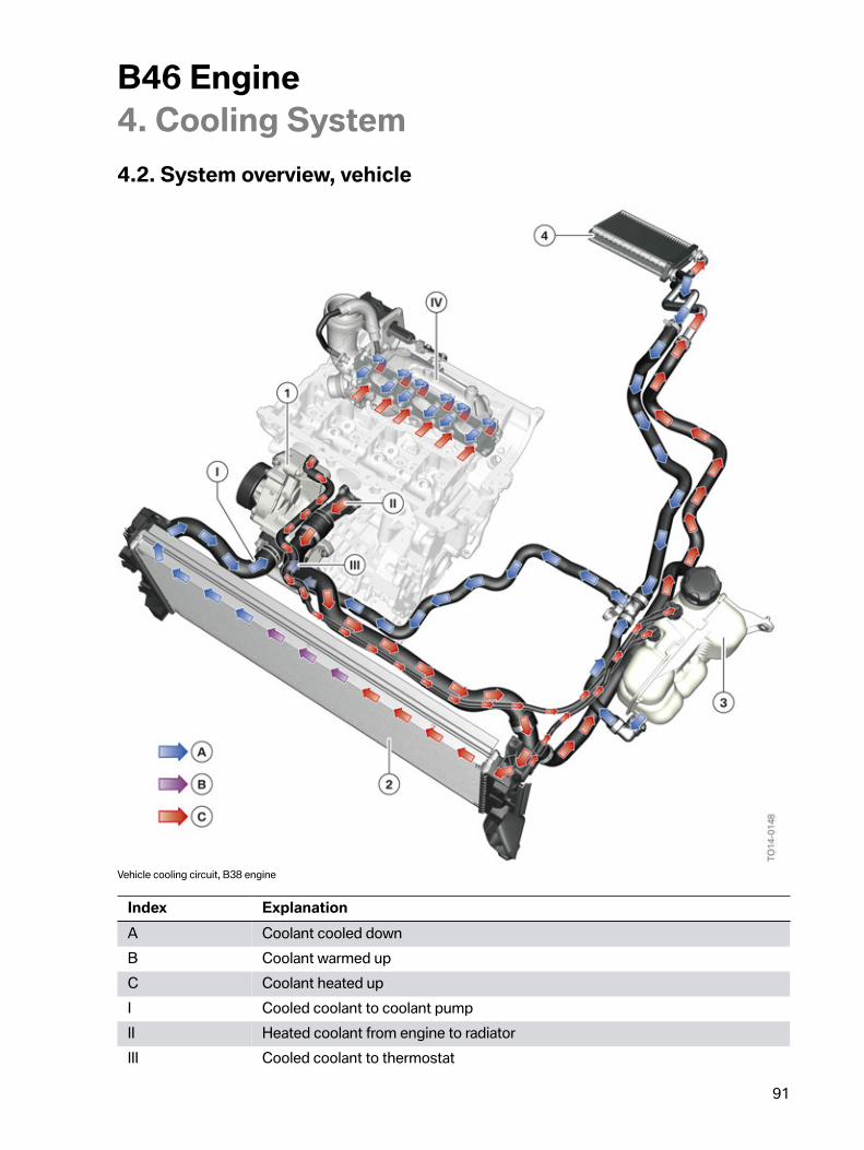
B46�Engine4.�Cooling�System
91
4.2.�System�overview,�vehicle
Vehicle�cooling�circuit,�B38�engine
Index ExplanationA Coolant�cooled�downB Coolant�warmed�upC Coolant�heated�upI Cooled�coolant�to�coolant�pumpII Heated�coolant�from�engine�to�radiatorIII Cooled�coolant�to�thermostat
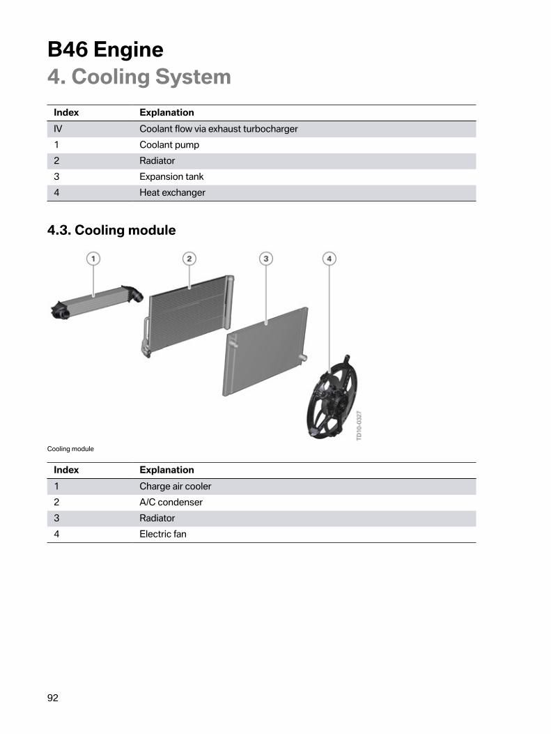
B46�Engine4.�Cooling�System
92
Index ExplanationIV Coolant�flow�via�exhaust�turbocharger1 Coolant�pump2 Radiator3 Expansion�tank4 Heat�exchanger
4.3.�Cooling�module
Cooling�module
Index Explanation1 Charge�air�cooler2 A/C�condenser3 Radiator4 Electric�fan
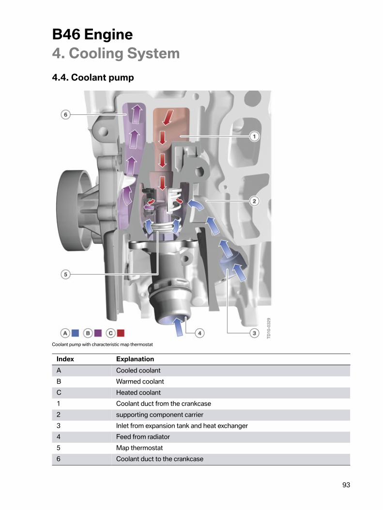
B46�Engine4.�Cooling�System
93
4.4.�Coolant�pump
Coolant�pump�with�characteristic�map�thermostat
Index ExplanationA Cooled�coolantB Warmed�coolantC Heated�coolant1 Coolant�duct�from�the�crankcase2 supporting�component�carrier3 Inlet�from�expansion�tank�and�heat�exchanger4 Feed�from�radiator5 Map�thermostat6 Coolant�duct�to�the�crankcase
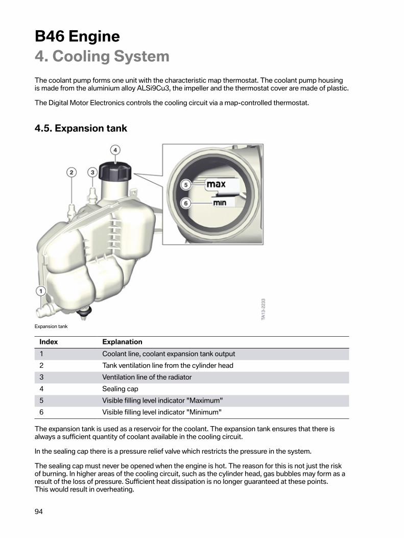
B46�Engine4.�Cooling�System
94
The�coolant�pump�forms�one�unit�with�the�characteristic�map�thermostat.�The�coolant�pump�housingis�made�from�the�aluminium�alloy�ALSi9Cu3,�the�impeller�and�the�thermostat�cover�are�made�of�plastic.
The�Digital�Motor�Electronics�controls�the�cooling�circuit�via�a�map-controlled�thermostat.
4.5.�Expansion�tank
Expansion�tank
Index Explanation1 Coolant�line,�coolant�expansion�tank�output2 Tank�ventilation�line�from�the�cylinder�head3 Ventilation�line�of�the�radiator4 Sealing�cap5 Visible�filling�level�indicator�"Maximum"6 Visible�filling�level�indicator�"Minimum"
The�expansion�tank�is�used�as�a�reservoir�for�the�coolant.�The�expansion�tank�ensures�that�there�isalways�a�sufficient�quantity�of�coolant�available�in�the�cooling�circuit.
In�the�sealing�cap�there�is�a�pressure�relief�valve�which�restricts�the�pressure�in�the�system.
The�sealing�cap�must�never�be�opened�when�the�engine�is�hot.�The�reason�for�this�is�not�just�the�riskof�burning.�In�higher�areas�of�the�cooling�circuit,�such�as�the�cylinder�head,�gas�bubbles�may�form�as�aresult�of�the�loss�of�pressure.�Sufficient�heat�dissipation�is�no�longer�guaranteed�at�these�points.This�would�result�in�overheating.
B46�Engine4.�Cooling�System
95
There�is�a�visible�filling�level�indicator�in�the�expansion�tank.�The�filling�level�can�be�read�when�the�tankis�open.�The�filling�level�should�be�between�maximum�and�minimum�for�correct�filling.
4.6.�CoolantThe�familiar�coolant�with�a�silicone�base�is�used.�The�coolant�is�not�subject�to�a�change�interval.The�filling�is�designed�for�the�entire�service�life�of�the�engine.�For�work�which�requires�an�opening�ofthe�cooling�circuit�the�coolant�must�be�replaced.�The�precise�procedure�for�ventilating�the�coolingcircuit�can�be�found�in�the�current�repair�instructions.
The�cooling�system�must�only�be�filled�with�BMW-approved�coolant.�If�the�wrong�coolant�is�used,damage�to�the�coolant�pumps,�coolant�hoses,�radiators�and�cylinder�head�gasket�may�subtly�creep�in.
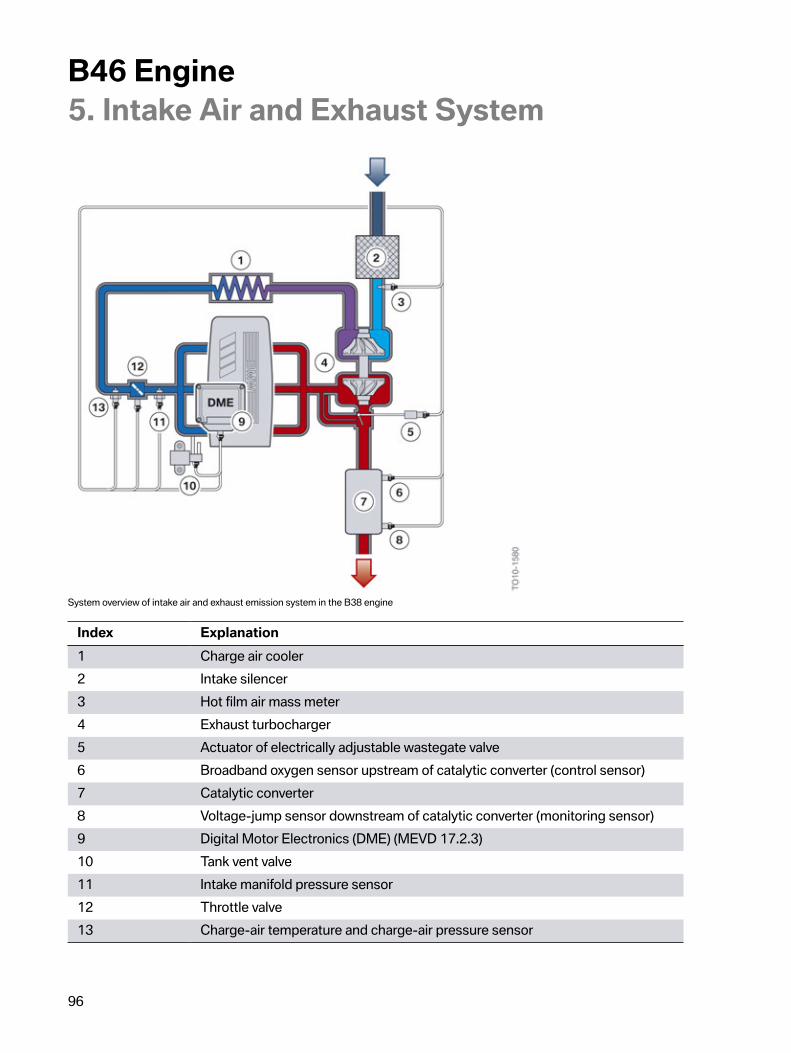
B46�Engine5.�Intake�Air�and�Exhaust�System
96
System�overview�of�intake�air�and�exhaust�emission�system�in�the�B38�engine
Index Explanation1 Charge�air�cooler2 Intake�silencer3 Hot�film�air�mass�meter4 Exhaust�turbocharger5 Actuator�of�electrically�adjustable�wastegate�valve6 Broadband�oxygen�sensor�upstream�of�catalytic�converter�(control�sensor)7 Catalytic�converter8 Voltage-jump�sensor�downstream�of�catalytic�converter�(monitoring�sensor)9 Digital�Motor�Electronics�(DME)�(MEVD�17.2.3)10 Tank�vent�valve11 Intake�manifold�pressure�sensor12 Throttle�valve13 Charge-air�temperature�and�charge-air�pressure�sensor
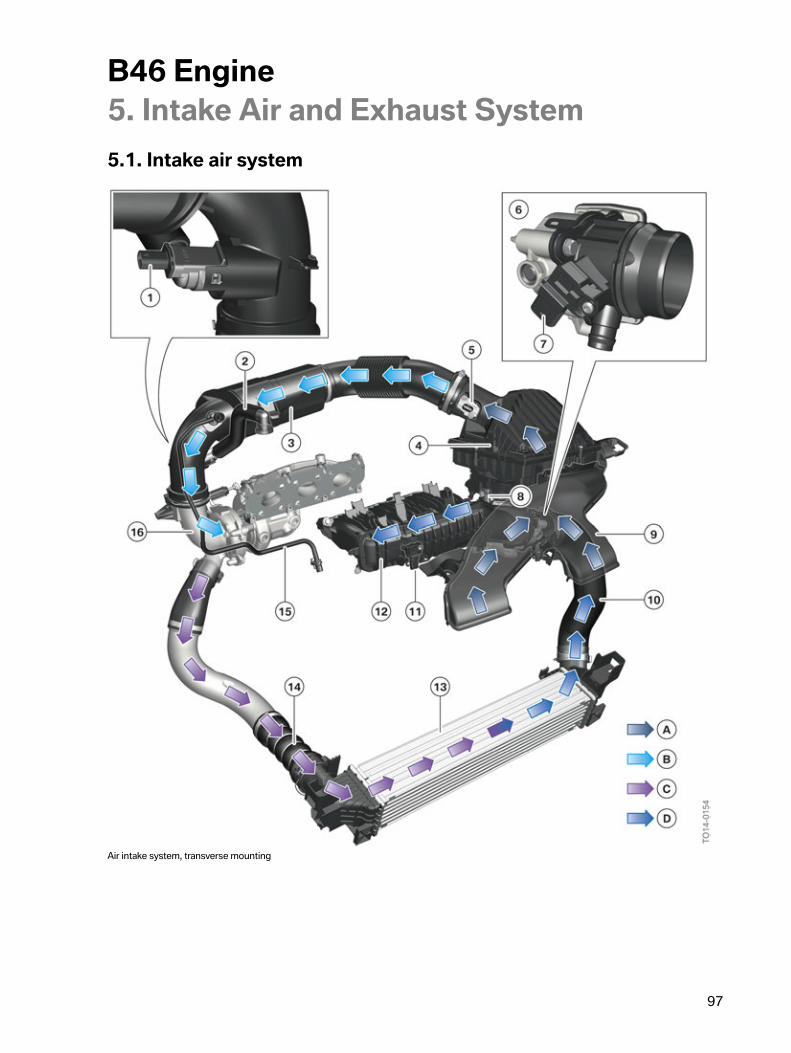
B46�Engine5.�Intake�Air�and�Exhaust�System
97
5.1.�Intake�air�system
Air�intake�system,�transverse�mounting
B46�Engine5.�Intake�Air�and�Exhaust�System
98
Index ExplanationA Fresh�airB Purified�airC Heated�charge�airD Cooled�charge�air1 Engine�ventilation�heating�(only�with�cold-climate�version)2 Blow-by�channel�into�clean�air�pipe�(turbocharged�operation)3 Clean�air�pipe�with�resonator4 Air�filter�housing5 Hot�film�air�mass�meter6 Throttle�valve�unit7 Charge�air�temperature�and�charging�pressure�sensor8 Connection�for�carbon�canister�regeneration�line9 Unfiltered-air�snorkel10 Charge�air�hose11 Intake�manifold�pressure�sensor12 Intake�manifold13 Charge�air�cooler14 Charge�air�hose15 Purge�air�line16 Exhaust�turbocharger�compressor,�inlet�side
The�air�duct�of�the�differentiated�air�intake�system�differs�depending�on�the�installation�position.This�documentation�only�deals�with�the�air�duct�in�the�transverse-mounted�Bx8�engine.
The�intake�unfiltered�air�reaches�the�intake�silencer�with�air�cleaner�via�the�unfiltered�air�line�with�intakeair�grille.�The�unfiltered�air�is�filtered�in�the�intake�silencer�with�air�cleaner�and�becomes�clean�air.�Thenthe�clean�air�is�directed�to�the�exhaust�turbocharger�via�the�hot�film�air�mass�meter�and�the�clean�airpipe�with�resonator.�The�blow-by�gases�from�the�crankcase�are�also�introduced,�depending�on�the�loadcondition,�into�the�clean�air�pipe�upstream�of�the�exhaust�turbocharger,�or�into�the�intake�ports�directly.
The�clean�air�is�compressed�and�heated�in�the�exhaust�turbocharger.�The�compressed,�warm�chargeair�is�further�directed�to�the�charge�air�cooler�in�the�charge�air�hose.�From�the�charge�air�cooler�the�nowcooled�charge�air�is�directed�to�the�throttle�valve�via�an�additional�charge�air�hose�and�the�adapter�pipewith�charge�air�temperature�and�charging�pressure�sensor.�The�cooled�charge�air�is�taken�to�the�intakeair�system�via�the�throttle�valve.
5.1.1.�Intake�silencerThe�intake�silencer�is�mounted�on�the�engine�and�contains�the�air�cleaner.�Air�which�has�been�inductedup�to�the�air�filter�is�referred�to�as�fresh�air.�After�leaving�the�air�filter�the�cleaned�air�is�referred�to�asclean�air.
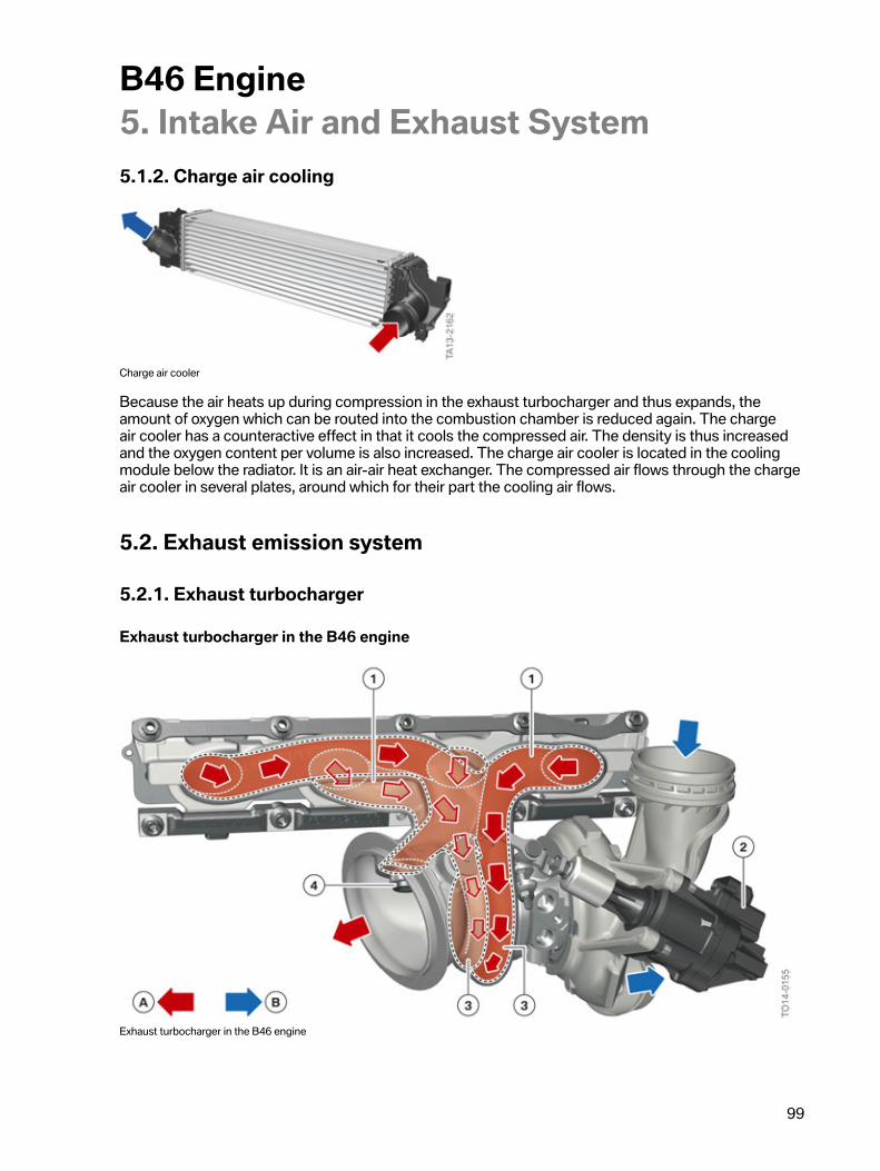
B46�Engine5.�Intake�Air�and�Exhaust�System
99
5.1.2.�Charge�air�cooling
Charge�air�cooler
Because�the�air�heats�up�during�compression�in�the�exhaust�turbocharger�and�thus�expands,�theamount�of�oxygen�which�can�be�routed�into�the�combustion�chamber�is�reduced�again.�The�chargeair�cooler�has�a�counteractive�effect�in�that�it�cools�the�compressed�air.�The�density�is�thus�increasedand�the�oxygen�content�per�volume�is�also�increased.�The�charge�air�cooler�is�located�in�the�coolingmodule�below�the�radiator.�It�is�an�air-air�heat�exchanger.�The�compressed�air�flows�through�the�chargeair�cooler�in�several�plates,�around�which�for�their�part�the�cooling�air�flows.
5.2.�Exhaust�emission�system
5.2.1.�Exhaust�turbocharger
Exhaust�turbocharger�in�the�B46�engine
Exhaust�turbocharger�in�the�B46�engine
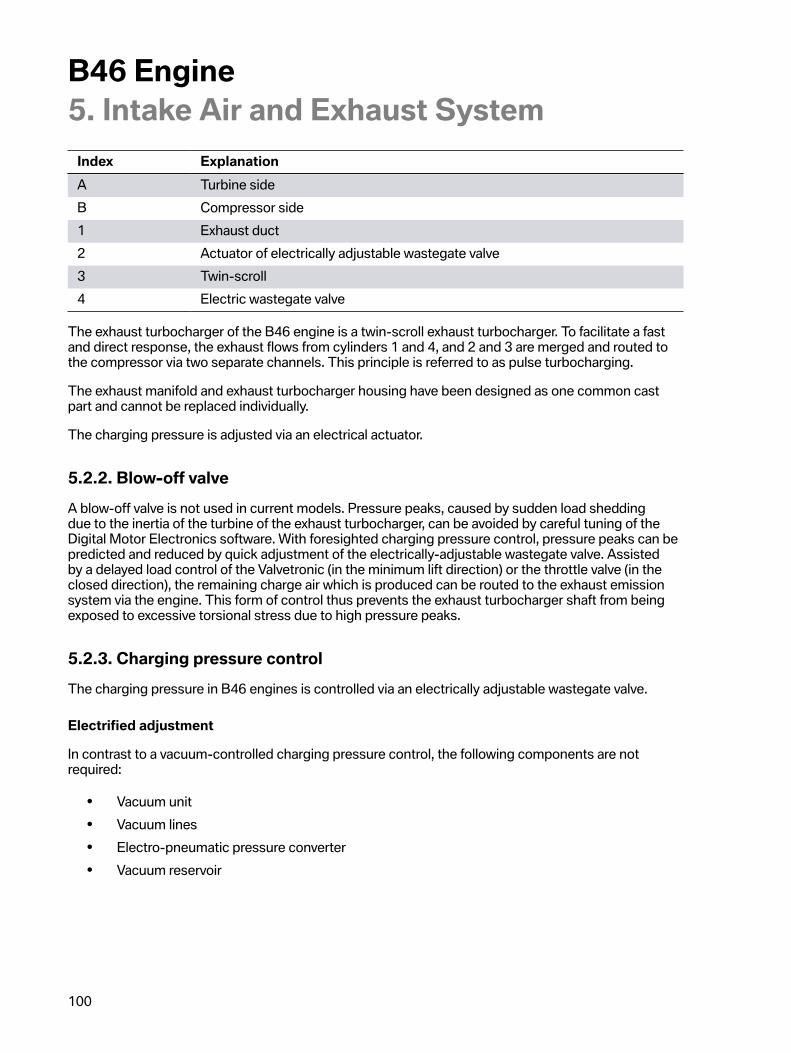
B46�Engine5.�Intake�Air�and�Exhaust�System
100
Index ExplanationA Turbine�sideB Compressor�side1 Exhaust�duct2 Actuator�of�electrically�adjustable�wastegate�valve3 Twin-scroll4 Electric�wastegate�valve
The�exhaust�turbocharger�of�the�B46�engine�is�a�twin-scroll�exhaust�turbocharger.�To�facilitate�a�fastand�direct�response,�the�exhaust�flows�from�cylinders�1�and�4,�and�2�and�3�are�merged�and�routed�tothe�compressor�via�two�separate�channels.�This�principle�is�referred�to�as�pulse�turbocharging.
The�exhaust�manifold�and�exhaust�turbocharger�housing�have�been�designed�as�one�common�castpart�and�cannot�be�replaced�individually.
The�charging�pressure�is�adjusted�via�an�electrical�actuator.
5.2.2.�Blow-off�valveA�blow-off�valve�is�not�used�in�current�models.�Pressure�peaks,�caused�by�sudden�load�sheddingdue�to�the�inertia�of�the�turbine�of�the�exhaust�turbocharger,�can�be�avoided�by�careful�tuning�of�theDigital�Motor�Electronics�software.�With�foresighted�charging�pressure�control,�pressure�peaks�can�bepredicted�and�reduced�by�quick�adjustment�of�the�electrically-adjustable�wastegate�valve.�Assistedby�a�delayed�load�control�of�the�Valvetronic�(in�the�minimum�lift�direction)�or�the�throttle�valve�(in�theclosed�direction),�the�remaining�charge�air�which�is�produced�can�be�routed�to�the�exhaust�emissionsystem�via�the�engine.�This�form�of�control�thus�prevents�the�exhaust�turbocharger�shaft�from�beingexposed�to�excessive�torsional�stress�due�to�high�pressure�peaks.
5.2.3.�Charging�pressure�controlThe�charging�pressure�in�B46�engines�is�controlled�via�an�electrically�adjustable�wastegate�valve.
Electrified�adjustment
In�contrast�to�a�vacuum-controlled�charging�pressure�control,�the�following�components�are�notrequired:
• Vacuum�unit• Vacuum�lines• Electro-pneumatic�pressure�converter• Vacuum�reservoir
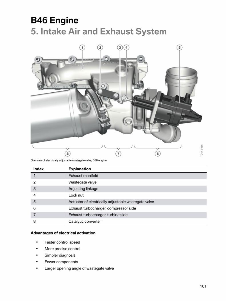
B46�Engine5.�Intake�Air�and�Exhaust�System
101
Overview�of�electrically�adjustable�wastegate�valve,�B38�engine
Index Explanation1 Exhaust�manifold2 Wastegate�valve3 Adjusting�linkage4 Lock�nut5 Actuator�of�electrically�adjustable�wastegate�valve6 Exhaust�turbocharger,�compressor�side7 Exhaust�turbocharger,�turbine�side8 Catalytic�converter
Advantages�of�electrical�activation
• Faster�control�speed• More�precise�control• Simpler�diagnosis• Fewer�components• Larger�opening�angle�of�wastegate�valve
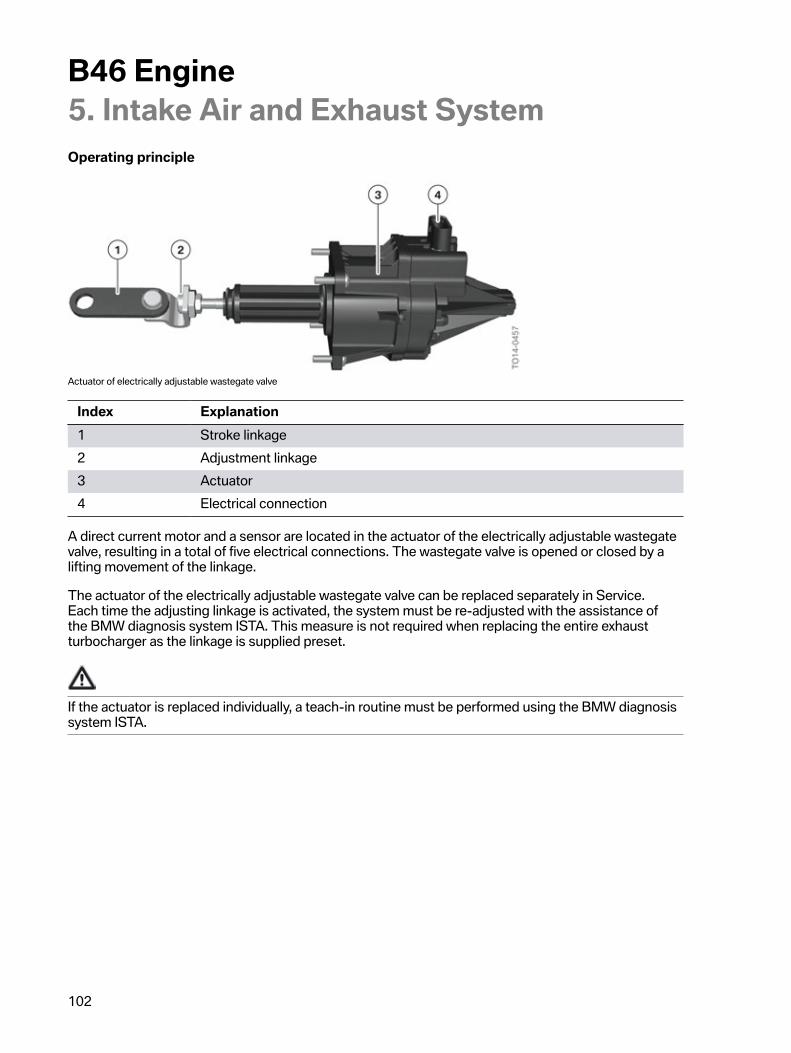
B46�Engine5.�Intake�Air�and�Exhaust�System
102
Operating�principle
Actuator�of�electrically�adjustable�wastegate�valve
Index Explanation1 Stroke�linkage2 Adjustment�linkage3 Actuator4 Electrical�connection
A�direct�current�motor�and�a�sensor�are�located�in�the�actuator�of�the�electrically�adjustable�wastegatevalve,�resulting�in�a�total�of�five�electrical�connections.�The�wastegate�valve�is�opened�or�closed�by�alifting�movement�of�the�linkage.
The�actuator�of�the�electrically�adjustable�wastegate�valve�can�be�replaced�separately�in�Service.Each�time�the�adjusting�linkage�is�activated,�the�system�must�be�re-adjusted�with�the�assistance�ofthe�BMW�diagnosis�system�ISTA.�This�measure�is�not�required�when�replacing�the�entire�exhaustturbocharger�as�the�linkage�is�supplied�preset.
If�the�actuator�is�replaced�individually,�a�teach-in�routine�must�be�performed�using�the�BMW�diagnosissystem�ISTA.
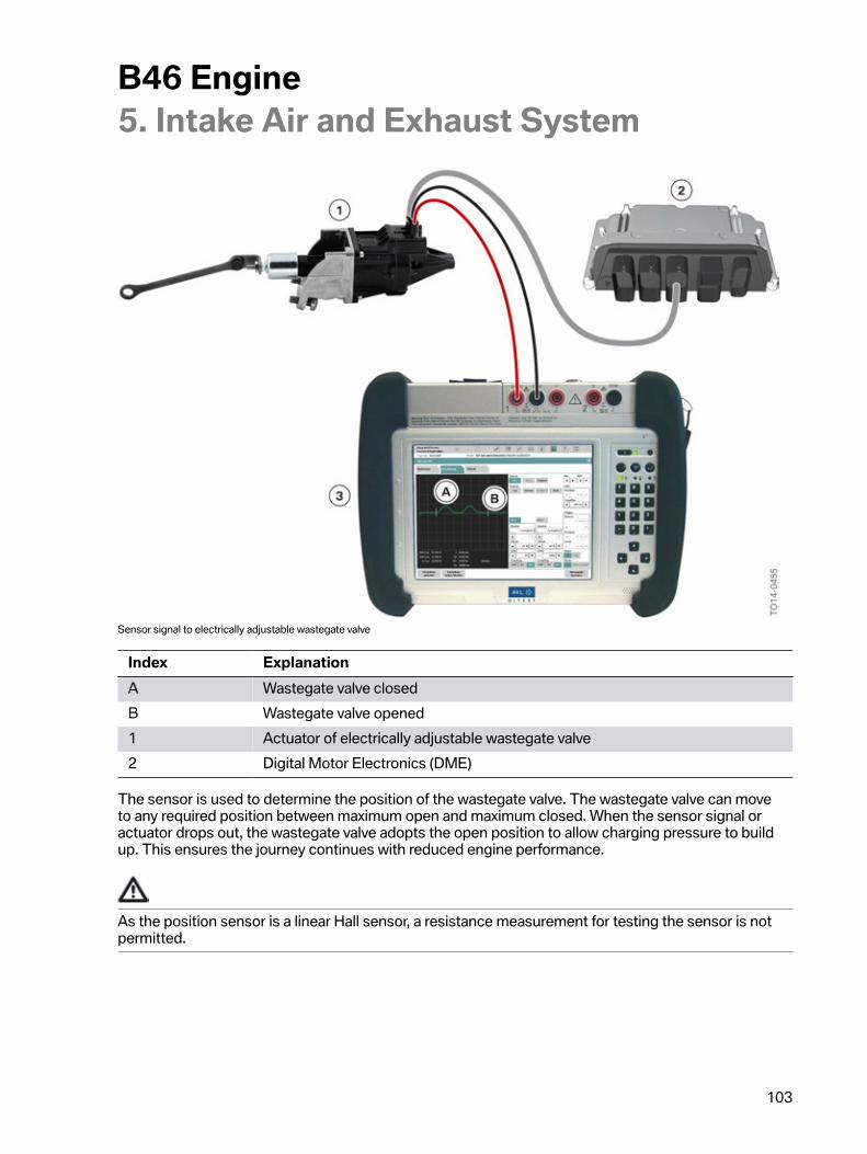
B46�Engine5.�Intake�Air�and�Exhaust�System
103
Sensor�signal�to�electrically�adjustable�wastegate�valve
Index ExplanationA Wastegate�valve�closedB Wastegate�valve�opened1 Actuator�of�electrically�adjustable�wastegate�valve2 Digital�Motor�Electronics�(DME)
The�sensor�is�used�to�determine�the�position�of�the�wastegate�valve.�The�wastegate�valve�can�moveto�any�required�position�between�maximum�open�and�maximum�closed.�When�the�sensor�signal�oractuator�drops�out,�the�wastegate�valve�adopts�the�open�position�to�allow�charging�pressure�to�buildup.�This�ensures�the�journey�continues�with�reduced�engine�performance.
As�the�position�sensor�is�a�linear�Hall�sensor,�a�resistance�measurement�for�testing�the�sensor�is�notpermitted.
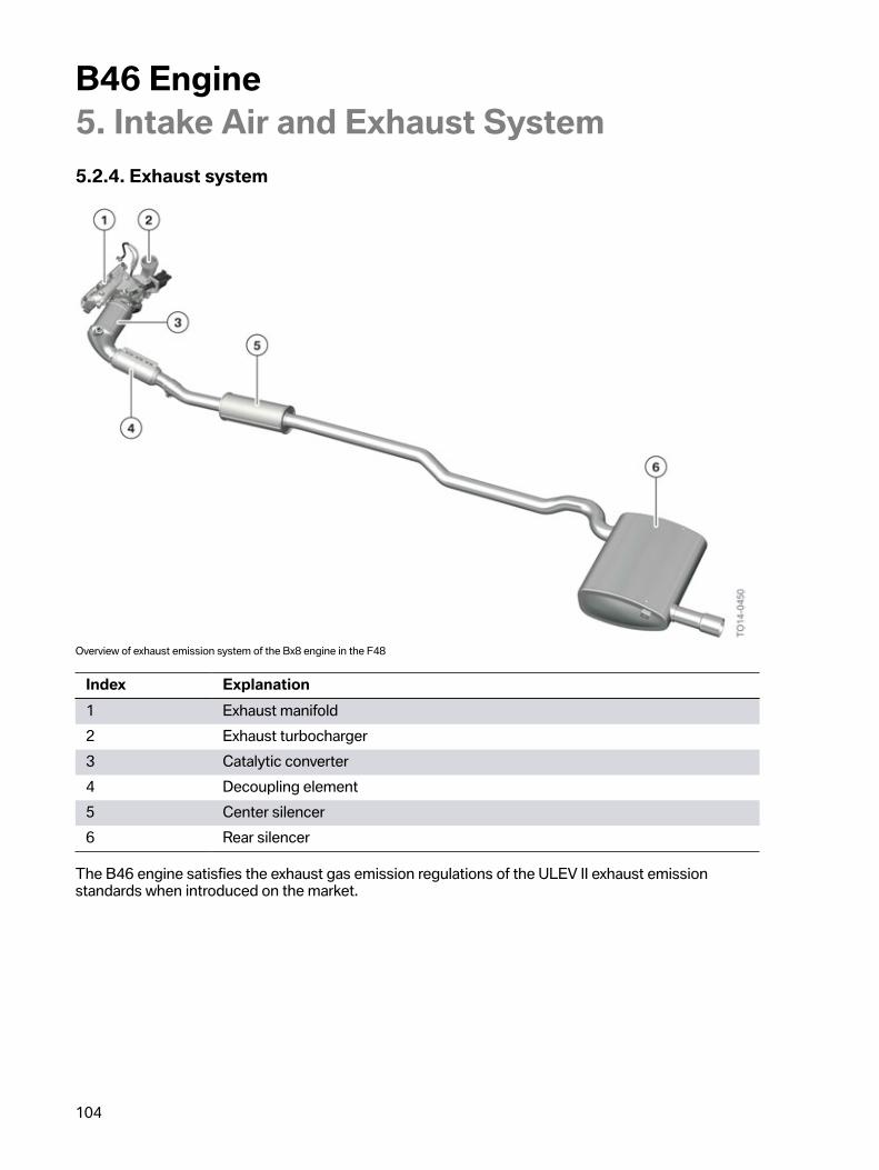
B46�Engine5.�Intake�Air�and�Exhaust�System
104
5.2.4.�Exhaust�system
Overview�of�exhaust�emission�system�of�the�Bx8�engine�in�the�F48
Index Explanation1 Exhaust�manifold2 Exhaust�turbocharger3 Catalytic�converter4 Decoupling�element5 Center�silencer6 Rear�silencer
The�B46�engine�satisfies�the�exhaust�gas�emission�regulations�of�the�ULEV�II�exhaust�emissionstandards�when�introduced�on�the�market.
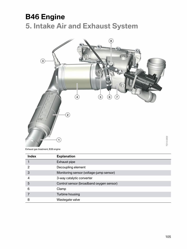
B46�Engine5.�Intake�Air�and�Exhaust�System
105
Exhaust�gas�treatment,�B38�engine
Index Explanation1 Exhaust�pipe2 Decoupling�element3 Monitoring�sensor�(voltage-jump�sensor)4 3-way�catalytic�converter5 Control�sensor�(broadband�oxygen�sensor)6 Clamp7 Turbine�housing8 Wastegate�valve
B46�Engine5.�Intake�Air�and�Exhaust�System
106
Measures�for�reduction�of�exhaust�gas�emissions
• Precise�and�fast�charging�pressure�control.• Catalytic�converter�heating�during�cold�start.• Positioning�of�catalytic�converter�near�engine.• New�LSF�Xfour�voltage-jump�sensor�by�Bosch.
Catalytic�converter�heating
When�starting�the�combustion�engine�from�cold,�the�wastegate�valve�is�opened�as�wide�as�possibleand�the�ignition�point�is�adjusted�to�retard.�The�retarded�ignition�point�delays�the�combustion�processwhich�in�turn�supports�the�heat�input�for�heating�of�the�catalytic�converter.�As�the�turbine�housing�isshort,�it�has�been�possible�to�position�the�catalytic�converter�very�close�to�the�wastegate�valve.�As�theexhaust�gas�flows�into�the�catalytic�converter�at�the�perfect�angle�and�because�of�its�position�closeto�the�engine,�the�catalytic�converter�reaches�its�operating�temperature�very�quickly.�If�the�wastegatevalve�is�opened�when�cold,�pulsation�of�the�exhaust�gas�may�cause�vibrations�in�the�wastegate�valve,which�are�perceived�as�noise.�This�is�not�due�to�a�defective�component,�and�is�normal�running�noise.This�noise�becomes�less�audible�as�the�temperature�of�the�component�increases.
Control�sensor
With�a�stoichiometric�air/fuel�ratio�(λ=1),�the�proportion�of�oxygen�in�the�exhaust�gas�is�ideal�forconversion�of�the�pollutants�in�the�3-way�catalytic�converter.�By�measuring�the�oxygen�content�in�theexhaust�gas,�the�oxygen�sensor�of�the�Digital�Motor�Electronics�delivers�important�information�formixture�preparation.
A�broadband�oxygen�sensor�with�the�designation�LSU�ADV�has�been�specially�developed�for�engineswith�exhaust�turbochargers�and�is�used�as�the�control�sensor.�One�of�the�major�characteristics�ofbroadband�oxygen�sensors�is�their�extensive�measuring�range.�The�measuring�range�of�the�LSU�ADVis�from�a�lambda�of�λ=0.65�to�λ=air.
The�broadband�oxygen�sensor�LSU�ADV�is�a�combination�of�a�measuring�cell�and�pump�cell.�There�isa�small�diffusion�gap�between�these�two�cells�which�serves�as�a�measuring�chamber�and�is�connectedto�the�exhaust�gas�duct.�The�measuring�cell�operates�according�to�the�principle�of�a�voltage-jumpsensor�and�measures�the�residual�oxygen�content�in�the�exhaust�gas.�If�the�fuel-air�mixture�is�too�lean(λ�>�1),�the�control�electronics�applies�voltage�to�the�pump�cell�so�that�oxygen�ions�are�pumped�outof�the�diffusion�gap.�If�the�mixture�is�too�rich�(λ�<�1),�oxygen�ions�are�pumped�into�the�diffusion�gapby�activating�the�pump�cell�accordingly.�The�pump�flow�required�to�control�the�pump�cell�is�directlyproportional�to�the�oxygen�concentration�and�therefore�serves�as�the�control�variable�for�the�air�ratio.
The�control�strategy�has�been�devised�so�that�the�oxygen�concentration�in�the�area�of�the�diffusiongap�corresponds�to�an�air�ratio�of�λ�=�1.�As�this�control�method�is�extremely�fast�and�incrediblyaccurate,�the�voltage�value�of�the�measuring�cell�always�remains�at�a�constant�level�(450�mV).
The�following�graphic�shows�the�two�voltage�curves�of�the�measuring�cell�and�the�pump�cell�when�theengine�is�in�operation:
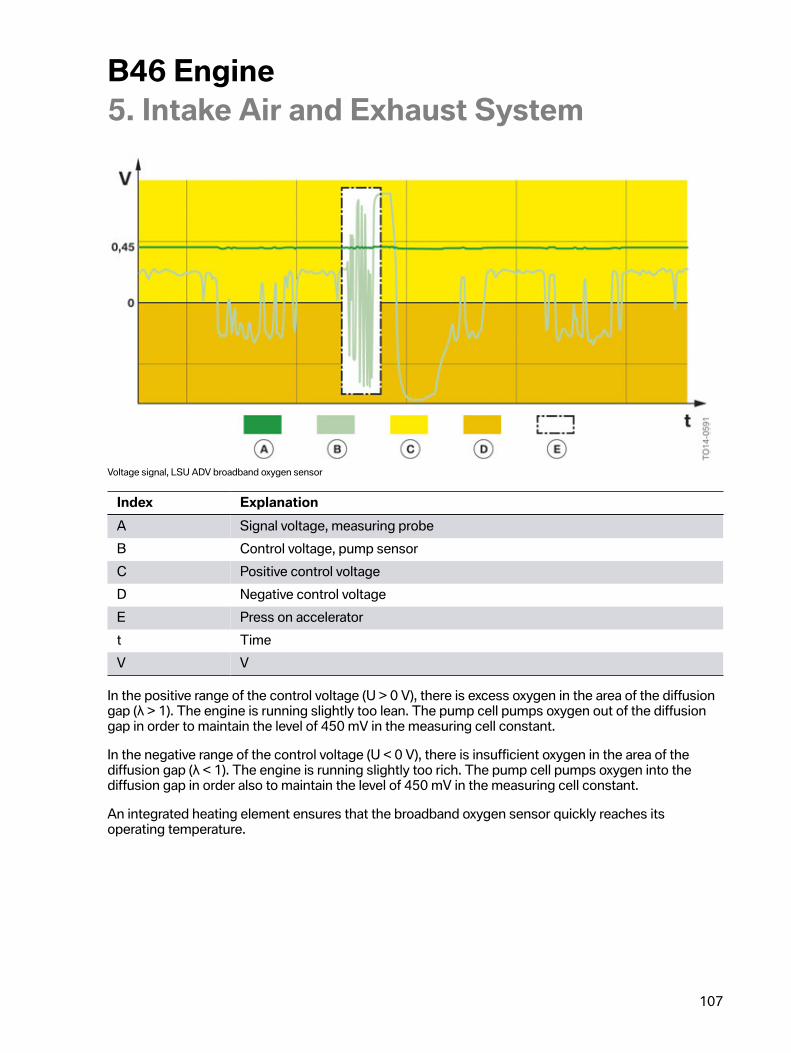
B46�Engine5.�Intake�Air�and�Exhaust�System
107
Voltage�signal,�LSU�ADV�broadband�oxygen�sensor
Index ExplanationA Signal�voltage,�measuring�probeB Control�voltage,�pump�sensorC Positive�control�voltageD Negative�control�voltageE Press�on�acceleratort TimeV V
In�the�positive�range�of�the�control�voltage�(U�>�0�V),�there�is�excess�oxygen�in�the�area�of�the�diffusiongap�(λ�>�1).�The�engine�is�running�slightly�too�lean.�The�pump�cell�pumps�oxygen�out�of�the�diffusiongap�in�order�to�maintain�the�level�of�450�mV�in�the�measuring�cell�constant.
In�the�negative�range�of�the�control�voltage�(U�<�0�V),�there�is�insufficient�oxygen�in�the�area�of�thediffusion�gap�(λ�<�1).�The�engine�is�running�slightly�too�rich.�The�pump�cell�pumps�oxygen�into�thediffusion�gap�in�order�also�to�maintain�the�level�of�450�mV�in�the�measuring�cell�constant.
An�integrated�heating�element�ensures�that�the�broadband�oxygen�sensor�quickly�reaches�itsoperating�temperature.
B46�Engine5.�Intake�Air�and�Exhaust�System
108
Connections,�broadband�oxygen�sensor
• Positive�terminal�of�pump�cell• Negative�terminal�of�pump�cell�and�measuring�cell• Heating�minus• Heating�plus• Positive�terminal�of�measuring�cell
Monitoring�sensor
A�new�voltage-jump�sensor�with�the�designation�LSF�Xfour�is�used�as�the�monitoring�sensor.�The�newoxygen�sensor�has�the�following�benefits:
• Sturdier�design• Small�installation�space• Higher�measuring�accuracy• Faster�control�readiness
The�oxygen�sensor�is�suitable�for�engine�start-stop�operation.�In�this�case,�the�sensor�must�be�heatedthroughout�the�entire�stop�phase.�The�voltage�required�during�the�heating�phase�is�7.5�volts�and�theheating�current�is�around�1�ampere.
Engine�operation Air�ratio Sensor�voltageRich�operating�phase λ=0.98 0.9 VLean�operating�phase λ=1.02 0.1 V
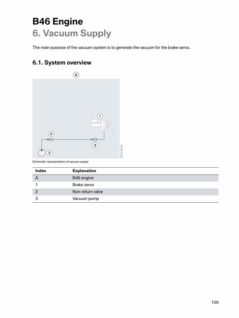
B46�Engine6.�Vacuum�Supply
109
The�main�purpose�of�the�vacuum�system�is�to�generate�the�vacuum�for�the�brake�servo.
6.1.�System�overview
Schematic�representation�of�vacuum�supply
Index ExplanationA B46�engine1 Brake�servo2 Non-return�valve3 Vacuum�pump
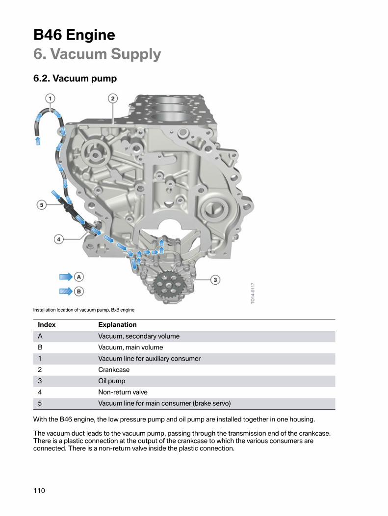
B46�Engine6.�Vacuum�Supply
110
6.2.�Vacuum�pump
Installation�location�of�vacuum�pump,�Bx8�engine
Index ExplanationA Vacuum,�secondary�volumeB Vacuum,�main�volume1 Vacuum�line�for�auxiliary�consumer2 Crankcase3 Oil�pump4 Non-return�valve5 Vacuum�line�for�main�consumer�(brake�servo)
With�the�B46�engine,�the�low�pressure�pump�and�oil�pump�are�installed�together�in�one�housing.
The�vacuum�duct�leads�to�the�vacuum�pump,�passing�through�the�transmission�end�of�the�crankcase.There�is�a�plastic�connection�at�the�output�of�the�crankcase�to�which�the�various�consumers�areconnected.�There�is�a�non-return�valve�inside�the�plastic�connection.
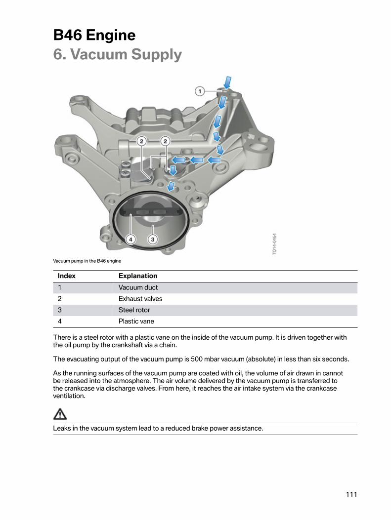
B46�Engine6.�Vacuum�Supply
111
Vacuum�pump�in�the�B46�engine
Index Explanation1 Vacuum�duct2 Exhaust�valves3 Steel�rotor4 Plastic�vane
There�is�a�steel�rotor�with�a�plastic�vane�on�the�inside�of�the�vacuum�pump.�It�is�driven�together�withthe�oil�pump�by�the�crankshaft�via�a�chain.
The�evacuating�output�of�the�vacuum�pump�is�500�mbar�vacuum�(absolute)�in�less�than�six�seconds.
As�the�running�surfaces�of�the�vacuum�pump�are�coated�with�oil,�the�volume�of�air�drawn�in�cannotbe�released�into�the�atmosphere.�The�air�volume�delivered�by�the�vacuum�pump�is�transferred�tothe�crankcase�via�discharge�valves.�From�here,�it�reaches�the�air�intake�system�via�the�crankcaseventilation.
Leaks�in�the�vacuum�system�lead�to�a�reduced�brake�power�assistance.
B46�Engine7.�Fuel�System
112
The�fuel�system�is�made�up�of�the�fuel�supply�and�fuel�preparation�systems.�The�fuel�supply�includesthe�fuel�tank�with�all�mounted�parts�and�the�fuel�lines�up�to�the�engine�compartment.
The�fuel�filter�lines�in�the�engine�compartment�and�all�the�fuel�system�parts�on�the�engine�belong�tothe�fuel�preparation�system.
The�fuel�supply�is�described�in�the�respective�product�information�bulletins�for�the�models.
Fuel�system,�Bx8�engine�in�the�F56
B46�Engine7.�Fuel�System
113
Index ExplanationA Fuel�preparationB Fuel�supply1 Digital�Motor�Electronics�(DME)2 Fuel�pump�control�module3 Electric�fuel�pump4 Fuel�filler�neck5 Emergency�release6 Dust�filter7 Fuel�tank�leak�diagnosis�system8 Fuel�tank9 High-pressure�pump10 Quantity�control�valve11 Rail�(high-pressure�accumulator)12 High-pressure�sensor13 Sensor�line,�rail�pressure�sensor14 Actuating�wire,�quantity�control�valve15 PWM�data�line16 Actuating�wire,�electric�fuel�pump�(three-phase�line�U,�V,�W)
7.1.�Fuel�pump�control�moduleIn�contrast�to�the�EKPS�control�unit�previously�used,�the�new�gas�engines�have�a�fuel�pump�controlmodule.�The�fuel�pump�control�module�is�not�shown�in�the�control�unit�overview.�The�fuel�pumpcontrol�module�is�responsible�for�processing�information�about�the�necessary�fuel�pressure�fromthe�Digital�Motor�Electronics�(DME)�and�for�activating�the�electric�fuel�pump�according�to�theserequirements�via�a�three-phase�AC�voltage.
7.2.�Electric�fuel�pumpThe�electric�fuel�pump�is�activated�as�required.�The�requirements�are�calculated�by�the�Digital�MotorElectronics�(DME).�The�request�regarding�the�extent�of�the�fuel�low�pressure�is�sent�to�the�fuel�pumpcontrol�module�with�the�assistance�of�a�pulse-width�modulated�signal�(PWM�signal).�The�fuel�pumpcontrol�module�processes�the�pulse-width�modulated�signal�and�with�help�of�an�inverter�generates�athree-phase�AC�voltage�U,�V,�W�to�activate�the�three-phase�motor�of�the�electric�fuel�pump�accordingto�requirements.
If�the�PWM�data�line�is�disconnected,�the�electric�fuel�pump�is�activated�with�the�maximum�systemperformance.�If�a�PWM�data�line�is�interrupted,�this�only�leads�to�a�fault�code�entry.�The�customer�isnot�informed�about�this�status,�by�the�illumination�of�a�warning�and�indicator�light,�for�example.�Theelectric�fuel�pump�is�designed�for�continuous�full�load�operation�and�is�also�not�damaged�if�the�PWMdata�line�is�interrupted�for�an�longer�period.
B46�Engine7.�Fuel�System
114
There�is�no�fuel�pressure�sensor�in�the�low-pressure�range�of�the�fuel�system.�The�fuel�low�pressure�iscalculated�in�the�Digital�Motor�Electronics�based�on�a�mathematical�model.�The�power�consumption�ofthe�electric�fuel�pump�also�provides�information�on�the�fuel�low�pressure.�If�the�power�consumption�ishigh,�this�means�that�a�high�fuel�-�low�pressure�exists�and�if�the�power�consumption�is�low,�this�meansthat�a�lower�fuel�-�low�pressure�prevails.
The�following�table�provides�information�on�the�technical�data�of�the�electric�fuel�pump.
Technical�dataEngine�speed�range 2600�–�6000�rpmPressure�area 2.0�-�6.5�barSupply�voltage 12�VDelivery�rate�at�3200�rpm�and�3.5�bar >�80�liters/60�minutesDelivery�rate�at�4250�rpm�and�6.3�bar >�105�liters/60�minutesDelivery�rate�at�5600�rpm�and�5.3�bar >�190�liters/60�minutes
The�electric�fuel�pump�becomes�impermissibly�hot�with�excessive�dry�running�>�1�minute.There�is�a�risk�of�a�component�fault�
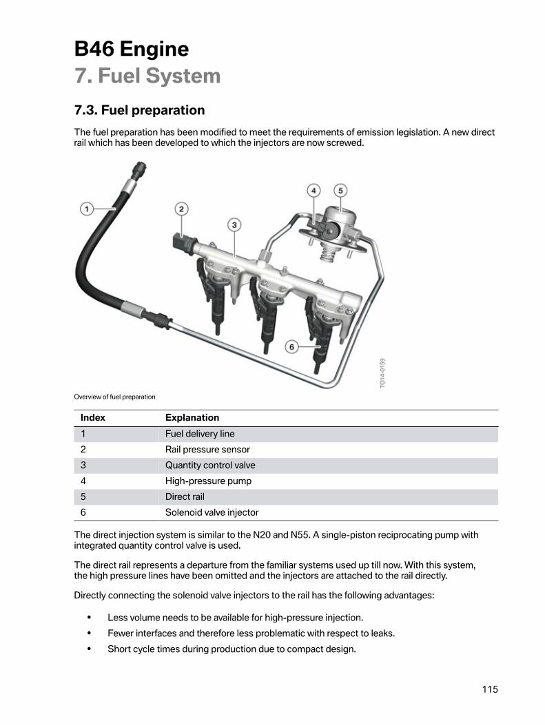
B46�Engine7.�Fuel�System
115
7.3.�Fuel�preparationThe�fuel�preparation�has�been�modified�to�meet�the�requirements�of�emission�legislation.�A�new�directrail�which�has�been�developed�to�which�the�injectors�are�now�screwed.
Overview�of�fuel�preparation
Index Explanation1 Fuel�delivery�line2 Rail�pressure�sensor3 Quantity�control�valve4 High-pressure�pump5 Direct�rail6 Solenoid�valve�injector
The�direct�injection�system�is�similar�to�the�N20�and�N55.�A�single-piston�reciprocating�pump�withintegrated�quantity�control�valve�is�used.
The�direct�rail�represents�a�departure�from�the�familiar�systems�used�up�till�now.�With�this�system,the�high�pressure�lines�have�been�omitted�and�the�injectors�are�attached�to�the�rail�directly.
Directly�connecting�the�solenoid�valve�injectors�to�the�rail�has�the�following�advantages:
• Less�volume�needs�to�be�available�for�high-pressure�injection.• Fewer�interfaces�and�therefore�less�problematic�with�respect�to�leaks.• Short�cycle�times�during�production�due�to�compact�design.
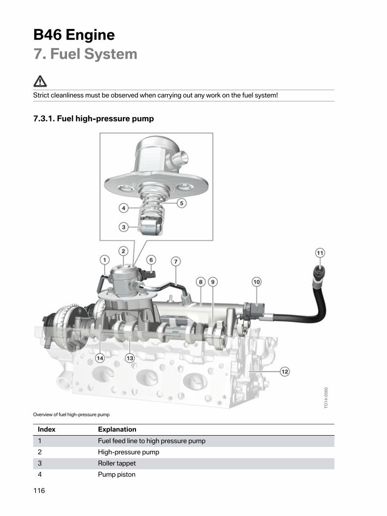
B46�Engine7.�Fuel�System
116
Strict�cleanliness�must�be�observed�when�carrying�out�any�work�on�the�fuel�system�
7.3.1.�Fuel�high-pressure�pump
Overview�of�fuel�high-pressure�pump
Index Explanation1 Fuel�feed�line�to�high�pressure�pump2 High-pressure�pump3 Roller�tappet4 Pump�piston
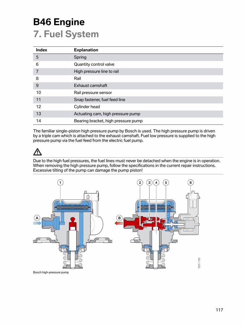
B46�Engine7.�Fuel�System
117
Index Explanation5 Spring6 Quantity�control�valve7 High�pressure�line�to�rail8 Rail9 Exhaust�camshaft10 Rail�pressure�sensor11 Snap�fastener,�fuel�feed�line12 Cylinder�head13 Actuating�cam,�high�pressure�pump14 Bearing�bracket,�high�pressure�pump
The�familiar�single-piston�high�pressure�pump�by�Bosch�is�used.�The�high�pressure�pump�is�drivenby�a�triple�cam�which�is�attached�to�the�exhaust�camshaft.�Fuel�low�pressure�is�supplied�to�the�highpressure�pump�via�the�fuel�feed�from�the�electric�fuel�pump.
Due�to�the�high�fuel�pressures,�the�fuel�lines�must�never�be�detached�when�the�engine�is�in�operation.When�removing�the�high�pressure�pump,�follow�the�specifications�in�the�current�repair�instructions.Excessive�tilting�of�the�pump�can�damage�the�pump�piston�
Bosch�high-pressure�pump
B46�Engine7.�Fuel�System
118
Index ExplanationA Low-pressure�connectionB High-pressure�connection1 Balancing�chamber2 High-pressure�non-return�valve3 Pressure-limiting�valve4 Pump�piston5 Quantity�control�valve6 Electrical�connection�of�quantity�control�valve
The�quantity�control�valve�at�the�high�pressure�pump�adjusts�the�fuel�pressure�in�the�rail.�Themaximum�pressure�in�the�rail�is�200�bar.�The�high�pressure�pump�contains�a�pressure�limiting�valvewhich�opens�at�a�pressure�of�245�bar.�The�quantity�control�valve�is�activated�via�a�pulse-width-modulated�(PWM)�signal�and�assumes�the�open�position�in�the�de-energized�state.�This�means�thepump�piston�of�the�high�pressure�pump�cannot�compress�the�fuel.
It�follows�that�the�high�pressure�pump�cannot�build�up�pressure�in�the�high-pressure�fuel�system�whenthe�quantity�control�valve�is�removed.�In�this�situation,�the�maximum�fuel�low�pressure�(6.5�bar)�wouldbe�present�in�the�rail�during�an�engine�start.�The�system�would�be�in�emergency�operation.�To�ensurethe�engine�remains�capable�of�running�in�this�state,�the�opening�period�of�the�solenoid�valve�injectorshas�been�extended�and�the�idle�speed�increased.�Although�the�vehicle�remains�drivable,�the�maximumengine�performance�is�not�available.
The�quantity�control�valve�is�not�resistant�to�continuous�current.�A�permanent�current�supply�with�12�Vdirect�current�voltage�would�render�the�component�defective.
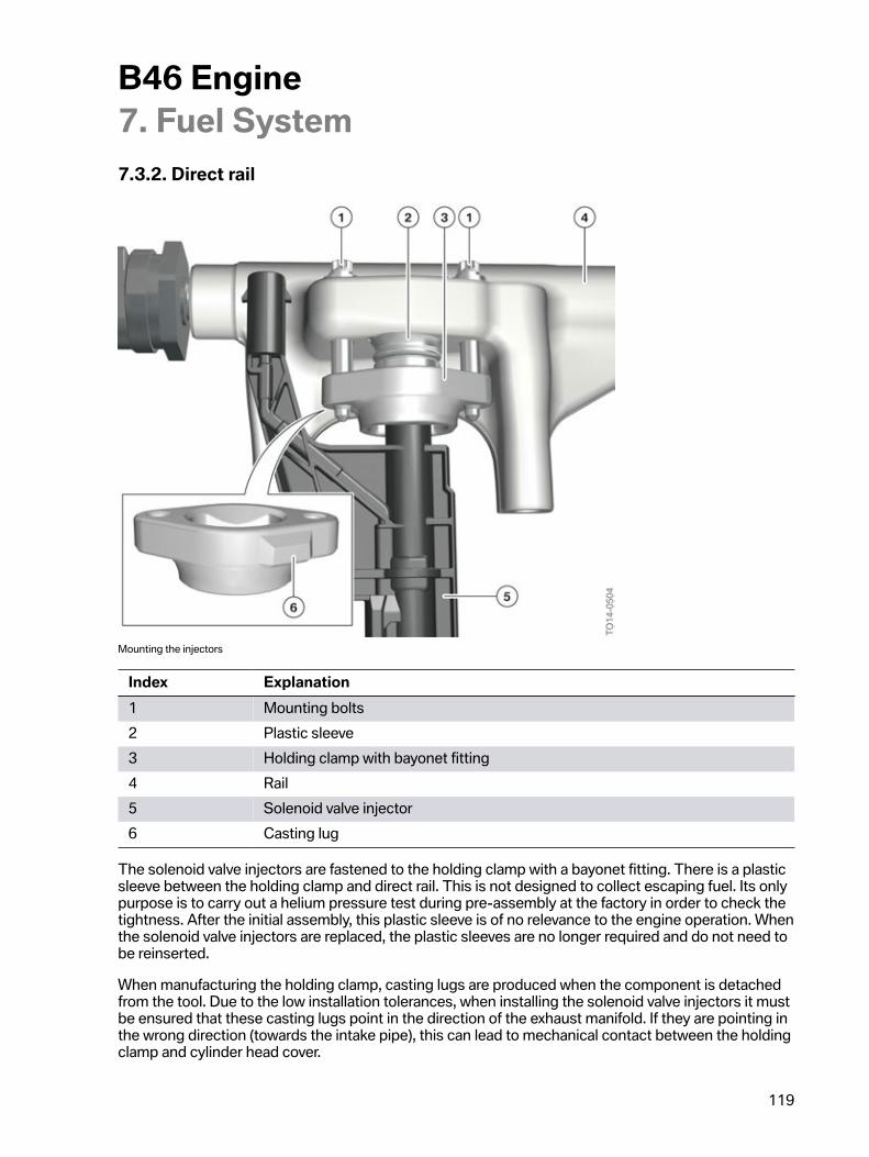
B46�Engine7.�Fuel�System
119
7.3.2.�Direct�rail
Mounting�the�injectors
Index Explanation1 Mounting�bolts2 Plastic�sleeve3 Holding�clamp�with�bayonet�fitting4 Rail5 Solenoid�valve�injector6 Casting�lug
The�solenoid�valve�injectors�are�fastened�to�the�holding�clamp�with�a�bayonet�fitting.�There�is�a�plasticsleeve�between�the�holding�clamp�and�direct�rail.�This�is�not�designed�to�collect�escaping�fuel.�Its�onlypurpose�is�to�carry�out�a�helium�pressure�test�during�pre-assembly�at�the�factory�in�order�to�check�thetightness.�After�the�initial�assembly,�this�plastic�sleeve�is�of�no�relevance�to�the�engine�operation.�Whenthe�solenoid�valve�injectors�are�replaced,�the�plastic�sleeves�are�no�longer�required�and�do�not�need�tobe�reinserted.
When�manufacturing�the�holding�clamp,�casting�lugs�are�produced�when�the�component�is�detachedfrom�the�tool.�Due�to�the�low�installation�tolerances,�when�installing�the�solenoid�valve�injectors�it�mustbe�ensured�that�these�casting�lugs�point�in�the�direction�of�the�exhaust�manifold.�If�they�are�pointing�inthe�wrong�direction�(towards�the�intake�pipe),�this�can�lead�to�mechanical�contact�between�the�holdingclamp�and�cylinder�head�cover.
B46�Engine7.�Fuel�System
120
The�mounting�bolts�of�the�holding�clamp�must�be�replaced�each�time�they�are�released.
The�shank�of�the�solenoid�valve�injectors�is�sensitive�to�high�tensile�forces�and�rotational�angles.When�removing�and�installing�the�solenoid�valve�injectors,�the�procedure�in�the�current�repairinstructions�must�be�followed��If�the�solenoid�valve�injectors�are�damaged,�fuel�may�be�discharged.
B46�Engine7.�Fuel�System
121
7.3.3.�Solenoid�valve�injector
Solenoid�valve�injector�HDEV�5.2
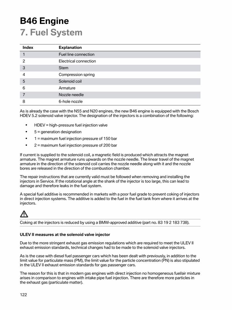
B46�Engine7.�Fuel�System
122
Index Explanation1 Fuel�line�connection2 Electrical�connection3 Stem4 Compression�spring5 Solenoid�coil6 Armature7 Nozzle�needle8 6-hole�nozzle
As�is�already�the�case�with�the�N55�and�N20�engines,�the�new�B46�engine�is�equipped�with�the�BoschHDEV�5.2�solenoid�valve�injector.�The�designation�of�the�injectors�is�a�combination�of�the�following:
• HDEV�=�high-pressure�fuel�injection�valve• 5�=�generation�designation• 1�=�maximum�fuel�injection�pressure�of�150�bar• 2�=�maximum�fuel�injection�pressure�of�200�bar
If�current�is�supplied�to�the�solenoid�coil,�a�magnetic�field�is�produced�which�attracts�the�magnetarmature.�The�magnet�armature�runs�upwards�on�the�nozzle�needle.�The�linear�travel�of�the�magnetarmature�in�the�direction�of�the�solenoid�coil�carries�the�nozzle�needle�along�with�it�and�the�nozzlebores�are�released�in�the�direction�of�the�combustion�chamber.
The�repair�instructions�that�are�currently�valid�must�be�followed�when�removing�and�installing�theinjectors�in�Service.�If�the�rotational�angle�at�the�shank�of�the�injector�is�too�large,�this�can�lead�todamage�and�therefore�leaks�in�the�fuel�system.
A�special�fuel�additive�is�recommended�in�markets�with�a�poor�fuel�grade�to�prevent�coking�of�injectorsin�direct�injection�systems.�The�additive�is�added�to�the�fuel�in�the�fuel�tank�from�where�it�arrives�at�theinjectors.
Coking�at�the�injectors�is�reduced�by�using�a�BMW-approved�additive�(part�no.�83�19�2�183�738).
ULEV�II�measures�at�the�solenoid�valve�injector
Due�to�the�more�stringent�exhaust�gas�emission�regulations�which�are�required�to�meet�the�ULEV�IIexhaust�emission�standards,�technical�changes�had�to�be�made�to�the�solenoid�valve�injectors.
As�is�the�case�with�diesel�fuel�passenger�cars�which�has�been�dealt�with�previously,�in�addition�to�thelimit�value�for�particulate�mass�(PM),�the�limit�value�for�the�particle�concentration�(PN)�is�also�stipulatedin�the�ULEV�II�exhaust�emission�standards�for�gas�passenger�cars.
The�reason�for�this�is�that�in�modern�gas�engines�with�direct�injection�no�homogeneous�fuel/air�mixturearises�in�comparison�to�engines�with�intake�pipe�fuel�injection.�There�are�therefore�more�particles�inthe�exhaust�gas�(particulate�matter).
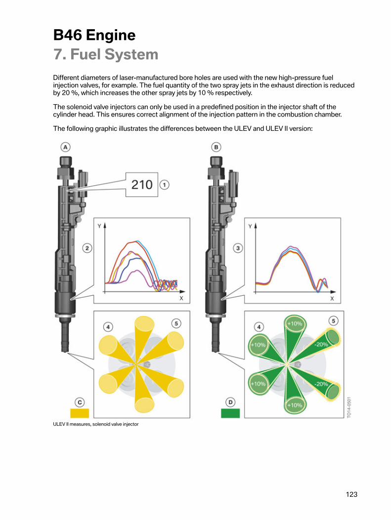
B46�Engine7.�Fuel�System
123
Different�diameters�of�laser-manufactured�bore�holes�are�used�with�the�new�high-pressure�fuelinjection�valves,�for�example.�The�fuel�quantity�of�the�two�spray�jets�in�the�exhaust�direction�is�reducedby�20 %,�which�increases�the�other�spray�jets�by�10 %�respectively.
The�solenoid�valve�injectors�can�only�be�used�in�a�predefined�position�in�the�injector�shaft�of�thecylinder�head.�This�ensures�correct�alignment�of�the�injection�pattern�in�the�combustion�chamber.
The�following�graphic�illustrates�the�differences�between�the�ULEV�and�ULEV�II�version:
ULEV�II�measures,�solenoid�valve�injector
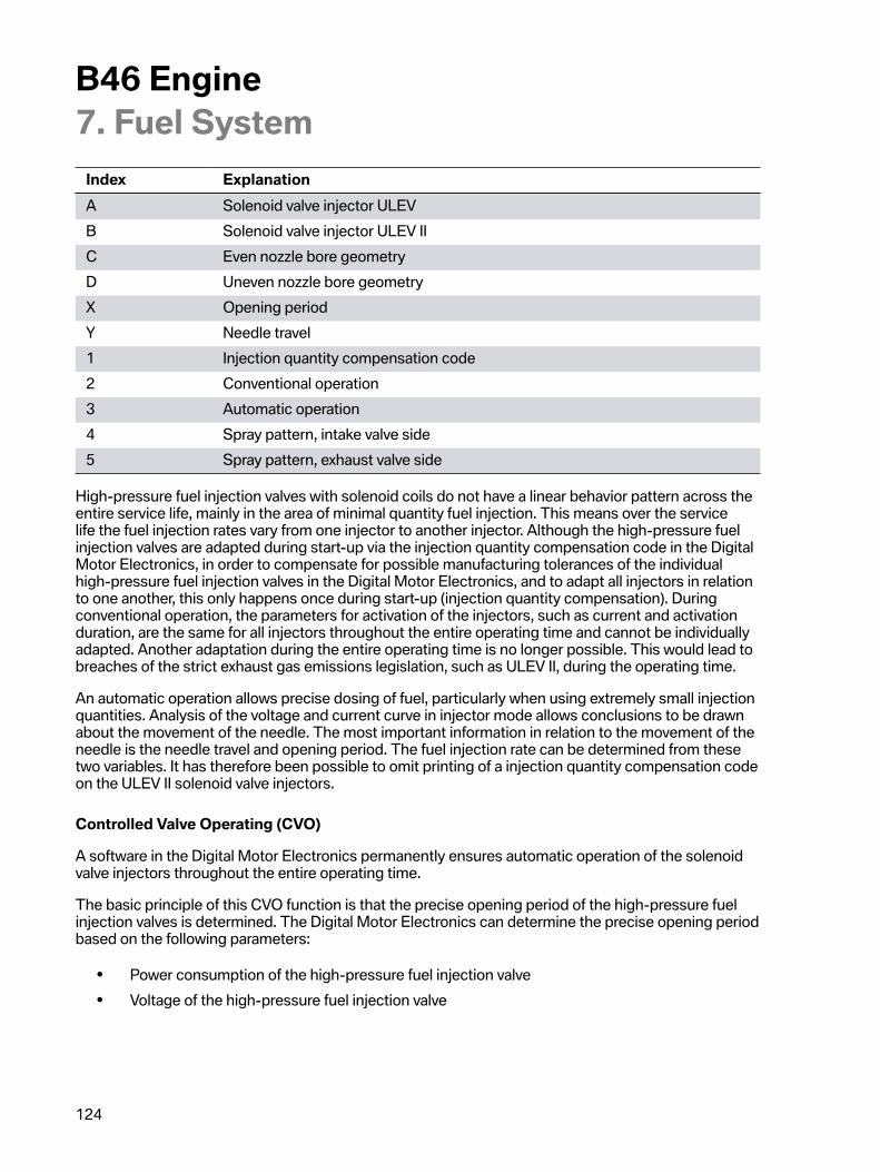
B46�Engine7.�Fuel�System
124
Index ExplanationA Solenoid�valve�injector�ULEVB Solenoid�valve�injector�ULEV�IIC Even�nozzle�bore�geometryD Uneven�nozzle�bore�geometryX Opening�periodY Needle�travel1 Injection�quantity�compensation�code2 Conventional�operation3 Automatic�operation4 Spray�pattern,�intake�valve�side5 Spray�pattern,�exhaust�valve�side
High-pressure�fuel�injection�valves�with�solenoid�coils�do�not�have�a�linear�behavior�pattern�across�theentire�service�life,�mainly�in�the�area�of�minimal�quantity�fuel�injection.�This�means�over�the�servicelife�the�fuel�injection�rates�vary�from�one�injector�to�another�injector.�Although�the�high-pressure�fuelinjection�valves�are�adapted�during�start-up�via�the�injection�quantity�compensation�code�in�the�DigitalMotor�Electronics,�in�order�to�compensate�for�possible�manufacturing�tolerances�of�the�individualhigh-pressure�fuel�injection�valves�in�the�Digital�Motor�Electronics,�and�to�adapt�all�injectors�in�relationto�one�another,�this�only�happens�once�during�start-up�(injection�quantity�compensation).�Duringconventional�operation,�the�parameters�for�activation�of�the�injectors,�such�as�current�and�activationduration,�are�the�same�for�all�injectors�throughout�the�entire�operating�time�and�cannot�be�individuallyadapted.�Another�adaptation�during�the�entire�operating�time�is�no�longer�possible.�This�would�lead�tobreaches�of�the�strict�exhaust�gas�emissions�legislation,�such�as�ULEV�II,�during�the�operating�time.
An�automatic�operation�allows�precise�dosing�of�fuel,�particularly�when�using�extremely�small�injectionquantities.�Analysis�of�the�voltage�and�current�curve�in�injector�mode�allows�conclusions�to�be�drawnabout�the�movement�of�the�needle.�The�most�important�information�in�relation�to�the�movement�of�theneedle�is�the�needle�travel�and�opening�period.�The�fuel�injection�rate�can�be�determined�from�thesetwo�variables.�It�has�therefore�been�possible�to�omit�printing�of�a�injection�quantity�compensation�codeon�the�ULEV�II�solenoid�valve�injectors.
Controlled�Valve�Operating�(CVO)
A�software�in�the�Digital�Motor�Electronics�permanently�ensures�automatic�operation�of�the�solenoidvalve�injectors�throughout�the�entire�operating�time.
The�basic�principle�of�this�CVO�function�is�that�the�precise�opening�period�of�the�high-pressure�fuelinjection�valves�is�determined.�The�Digital�Motor�Electronics�can�determine�the�precise�opening�periodbased�on�the�following�parameters:
• Power�consumption�of�the�high-pressure�fuel�injection�valve• Voltage�of�the�high-pressure�fuel�injection�valve
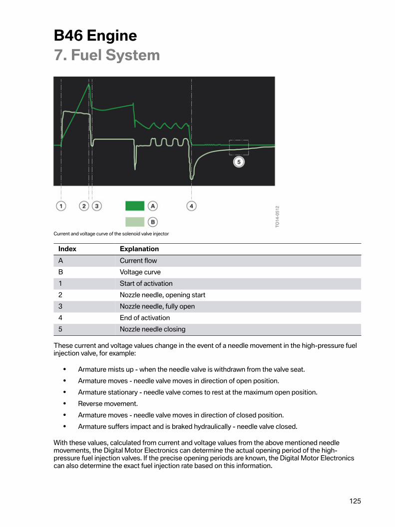
B46�Engine7.�Fuel�System
125
Current�and�voltage�curve�of�the�solenoid�valve�injector
Index ExplanationA Current�flowB Voltage�curve1 Start�of�activation2 Nozzle�needle,�opening�start3 Nozzle�needle,�fully�open4 End�of�activation5 Nozzle�needle�closing
These�current�and�voltage�values�change�in�the�event�of�a�needle�movement�in�the�high-pressure�fuelinjection�valve,�for�example:
• Armature�mists�up�-�when�the�needle�valve�is�withdrawn�from�the�valve�seat.• Armature�moves�-�needle�valve�moves�in�direction�of�open�position.• Armature�stationary�-�needle�valve�comes�to�rest�at�the�maximum�open�position.• Reverse�movement.• Armature�moves�-�needle�valve�moves�in�direction�of�closed�position.• Armature�suffers�impact�and�is�braked�hydraulically�-�needle�valve�closed.
With�these�values,�calculated�from�current�and�voltage�values�from�the�above�mentioned�needlemovements,�the�Digital�Motor�Electronics�can�determine�the�actual�opening�period�of�the�high-pressure�fuel�injection�valves.�If�the�precise�opening�periods�are�known,�the�Digital�Motor�Electronicscan�also�determine�the�exact�fuel�injection�rate�based�on�this�information.
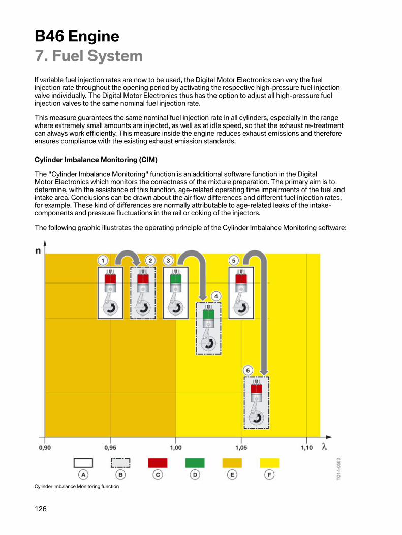
B46�Engine7.�Fuel�System
126
If�variable�fuel�injection�rates�are�now�to�be�used,�the�Digital�Motor�Electronics�can�vary�the�fuelinjection�rate�throughout�the�opening�period�by�activating�the�respective�high-pressure�fuel�injectionvalve�individually.�The�Digital�Motor�Electronics�thus�has�the�option�to�adjust�all�high-pressure�fuelinjection�valves�to�the�same�nominal�fuel�injection�rate.
This�measure�guarantees�the�same�nominal�fuel�injection�rate�in�all�cylinders,�especially�in�the�rangewhere�extremely�small�amounts�are�injected,�as�well�as�at�idle�speed,�so�that�the�exhaust�re-treatmentcan�always�work�efficiently.�This�measure�inside�the�engine�reduces�exhaust�emissions�and�thereforeensures�compliance�with�the�existing�exhaust�emission�standards.
Cylinder�Imbalance�Monitoring�(CIM)
The�"Cylinder�Imbalance�Monitoring"�function�is�an�additional�software�function�in�the�DigitalMotor�Electronics�which�monitors�the�correctness�of�the�mixture�preparation.�The�primary�aim�is�todetermine,�with�the�assistance�of�this�function,�age-related�operating�time�impairments�of�the�fuel�andintake�area.�Conclusions�can�be�drawn�about�the�air�flow�differences�and�different�fuel�injection�rates,for�example.�These�kind�of�differences�are�normally�attributable�to�age-related�leaks�of�the�intake-components�and�pressure�fluctuations�in�the�rail�or�coking�of�the�injectors.
The�following�graphic�illustrates�the�operating�principle�of�the�Cylinder�Imbalance�Monitoring�software:
Cylinder�Imbalance�Monitoring�function
B46�Engine7.�Fuel�System
127
Index ExplanationA Cylinder�in�normal�operationB Test�cylinder�with�higher�air/fuel�ratioC Cylinder�outside�the�toleranceD Cylinder�inside�the�toleranceE Rich�rangeF Lean�rangen Speed�of�crankshaftλ Air�ratio1 Cylinder�in�rich�range2 Test�cylinder�speed�constant3 Cylinder�in�ideal�range4 Test�cylinder�speed�slightly�slower5 Cylinder�in�lean�range6 Speed�of�test�cylinder�significantly�slower
The�function�is�cyclically�actuated�by�the�Digital�Motor�Electronics.�During�this�process,�the�air/fuelratio�is�increased�for�each�cylinder�in�succession�during�engine�operation.�At�the�same�time�as�the�air/fuel�ratio�in�the�test�cylinder�is�increased,�the�remaining�cylinders�are�enriched�in�order�to�maintainthe�overall�lambda�value�of�the�exhaust�gas�passage�within�the�range�λ=1.�This�ensures�perfectfunctionality�of�the�3-way�catalytic�converter.
If�a�test�cylinder�is�operated�when�the�air/fuel�ratio�is�too�low,�a�slight�increase�will�not�bring�about�achange�in�the�crankshaft�speed.
When�the�air/fuel�ratio�in�a�test�cylinder�is�increased�in�the�ideal�range,�this�brings�about�a�slight�changein�speed�at�the�crankshaft.
If�a�test�cylinder�is�operated�when�the�air/fuel�ratio�is�too�high,�the�speed�at�the�crankshaft�dropsrapidly.
The�engine�speed�variations�at�the�crankshaft�are�not�evaluated�directly,�but�rather�the�changes�insmooth�running�during�engine�operation.�Rough�running�of�the�cylinders�in�relation�to�one�another�isbalanced�out�by�a�so-called�'cylinder�balancing�control'.�The�test�cylinder�in�the�rich�range�thereforebrings�about�a�minor�change�in�rough�running�and�the�test�cylinder�in�the�lean�range�brings�about�amajor�change�in�rough�running.
Mixture�errors�determined�are�stored�as�a�fault�code�entry�in�the�Digital�Motor�Electronics.�The�faultcode�entry�provides�information�about�which�cylinder�is�affected�and�the�rich�or�lean�value�determined.The�driver�is�informed�about�the�error�via�a�malfunction�indicator�lamp.
B46�Engine7.�Fuel�System
128
Service�note
When�replacing�the�injector,�the�taught-in�values�of�the�CVO�function�and�CIM�function�must�bereset.�This�is�done�with�the�assistance�of�the�BMW�diagnosis�system�ISTA.�Adjustment�functions�areavailable�in�the�service�functions.�In�order�to�inform�the�Digital�Motor�Electronics�about�the�injectorreplacement,�every�ULEV�II�solenoid�valve�injector�with�the�same�dummy�value�(215)�is�taught�in.Once�the�teach-in�procedure�has�been�successfully�completed,�the�stored�adaptations�are�reset�andnew�adaptations�are�taught�in�via�the�CVO�and�CIM�function.
When�the�solenoid�valve�injectors�are�replaced,�they�must�be�started�up�with�the�assistance�of�theBMW�diagnosis�system�ISTA.
B46�Engine8.�Engine�Electrical�System
129
8.1.�Digital�Motor�Electronics�(DME)Different�variants�of�the�Digital�Motor�Electronics�MEVD�17.2.3�are�used,�depending�on�the�chargecycle�method.�The�hardware�of�the�throttle�valve-controlled�engine�control�units�is�therefore�not�thesame�as�the�hardware�of�the�Valvetronic-controlled�engine�control�units.
The�control�unit�number�is�made�up�of�the�following:
• M�=�engine�electronics• E�=�electrical�load�control�(without�cable)• V�=�Valvetronic�control• D�=�direct�fuel�injection• 17�=�control�unit�generation• 2�=�Bosch-internal�project�number�for�BMW• 3�=�control�unit�index
The�Digital�Motor�Electronics�is�the�computing�and�switching�center.�Sensors�on�the�engine�andthe�vehicle�deliver�the�input�signals�and�actuators�implement�the�commands.�The�Digital�MotorElectronics�calculates�the�corresponding�activation�signals�for�the�actuators�from�the�input�signals,and�also�the�computing�models�and�characteristic�maps�stored.
The�operating�voltage�range�of�the�Digital�Motor�Electronics�is�between�6�and�16 volts.
An�ambient�pressure�sensor�and�a�temperature�sensor�are�integrated�in�the�Digital�Motor�Electronics.
The�ambient�pressure�sensor�permits�precise�determination�of�the�density�of�the�ambient�air.�Thisinformation�is�required�for�various�diagnostic�functions.�In�addition,�in�the�event�of�a�failure�of�the�hotfilm�air�mass�meter,�a�precise�substitute�value�can�be�calculated�for�the�cylinder�filling�with�the�help�ofadditional�input�variables.
The�temperature�sensor�measures�the�temperature�inside�the�control�unit.�If�the�temperature�thererises�too�sharply,�multiple�fuel�injection�is�reduced�for�example,�in�order�to�cool�the�output�stagesslightly�and�to�keep�the�temperature�inside�the�control�unit�in�a�non-critical�range.
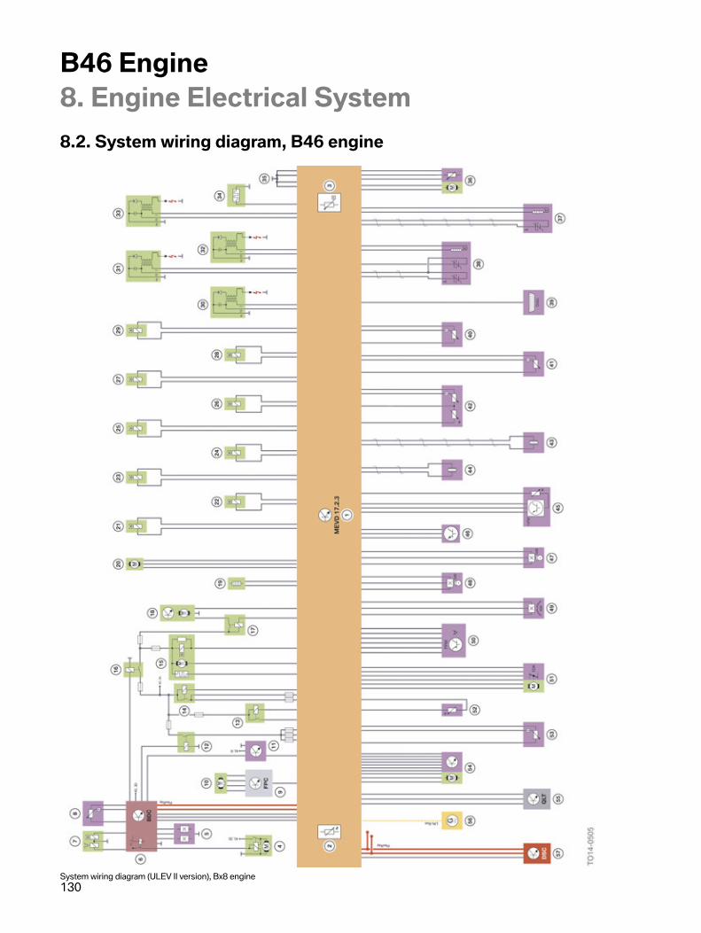
B46�Engine8.�Engine�Electrical�System
130
8.2.�System�wiring�diagram,�B46�engine
System�wiring�diagram�(ULEV�II�version),�Bx8�engine
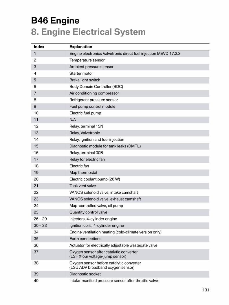
B46�Engine8.�Engine�Electrical�System
131
Index Explanation1 Engine�electronics�Valvetronic�direct�fuel�injection�MEVD�17.2.32 Temperature�sensor3 Ambient�pressure�sensor4 Starter�motor5 Brake�light�switch6 Body�Domain�Controller�(BDC)7 Air�conditioning�compressor8 Refrigerant�pressure�sensor9 Fuel�pump�control�module10 Electric�fuel�pump11 N/A12 Relay,�terminal�15N13 Relay,�Valvetronic14 Relay,�ignition�and�fuel�injection15 Diagnostic�module�for�tank�leaks�(DMTL)16 Relay,�terminal�30B17 Relay�for�electric�fan18 Electric�fan19 Map�thermostat20 Electric�coolant�pump�(20�W)21 Tank�vent�valve22 VANOS�solenoid�valve,�intake�camshaft23 VANOS�solenoid�valve,�exhaust�camshaft24 Map-controlled�valve,�oil�pump25 Quantity�control�valve26�–�29 Injectors,�4-cylinder�engine30�–�33 Ignition�coils,�4-cylinder�engine34 Engine�ventilation�heating�(cold-climate�version�only)35 Earth�connections36 Actuator�for�electrically�adjustable�wastegate�valve37 Oxygen�sensor�after�catalytic�converter
(LSF�Xfour�voltage-jump�sensor)38 Oxygen�sensor�before�catalytic�converter
(LSU�ADV�broadband�oxygen�sensor)39 Diagnostic�socket40 Intake-manifold�pressure�sensor�after�throttle�valve
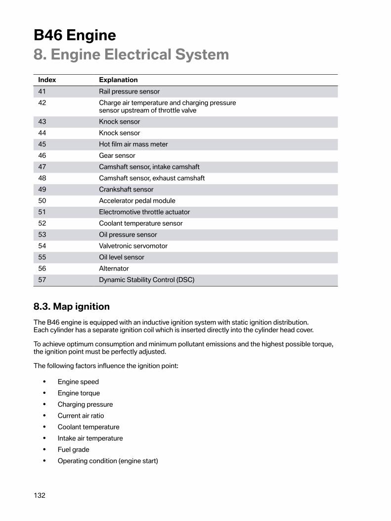
B46�Engine8.�Engine�Electrical�System
132
Index Explanation41 Rail�pressure�sensor42 Charge�air�temperature�and�charging�pressure
sensor�upstream�of�throttle�valve43 Knock�sensor44 Knock�sensor45 Hot�film�air�mass�meter46 Gear�sensor47 Camshaft�sensor,�intake�camshaft48 Camshaft�sensor,�exhaust�camshaft49 Crankshaft�sensor50 Accelerator�pedal�module51 Electromotive�throttle�actuator52 Coolant�temperature�sensor53 Oil�pressure�sensor54 Valvetronic�servomotor55 Oil�level�sensor56 Alternator57 Dynamic�Stability�Control�(DSC)
8.3.�Map�ignitionThe�B46�engine�is�equipped�with�an�inductive�ignition�system�with�static�ignition�distribution.Each�cylinder�has�a�separate�ignition�coil�which�is�inserted�directly�into�the�cylinder�head�cover.
To�achieve�optimum�consumption�and�minimum�pollutant�emissions�and�the�highest�possible�torque,the�ignition�point�must�be�perfectly�adjusted.
The�following�factors�influence�the�ignition�point:
• Engine�speed• Engine�torque• Charging�pressure• Current�air�ratio• Coolant�temperature• Intake�air�temperature• Fuel�grade• Operating�condition�(engine�start)
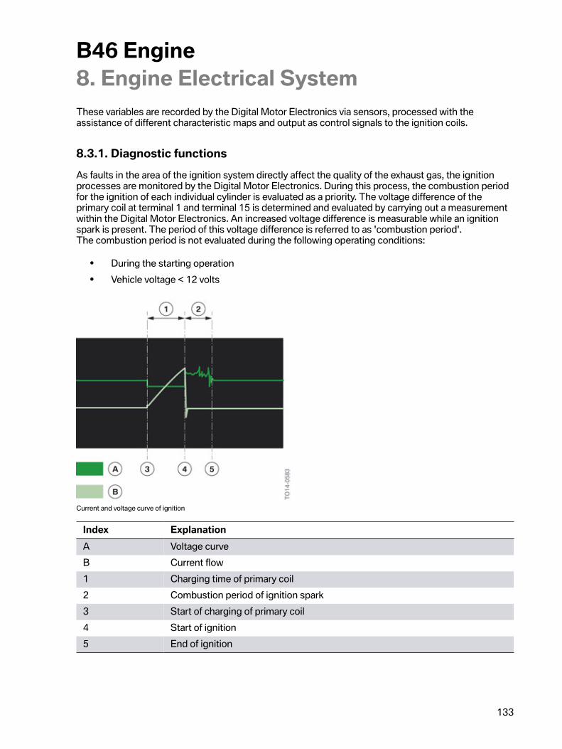
B46�Engine8.�Engine�Electrical�System
133
These�variables�are�recorded�by�the�Digital�Motor�Electronics�via�sensors,�processed�with�theassistance�of�different�characteristic�maps�and�output�as�control�signals�to�the�ignition�coils.
8.3.1.�Diagnostic�functionsAs�faults�in�the�area�of�the�ignition�system�directly�affect�the�quality�of�the�exhaust�gas,�the�ignitionprocesses�are�monitored�by�the�Digital�Motor�Electronics.�During�this�process,�the�combustion�periodfor�the�ignition�of�each�individual�cylinder�is�evaluated�as�a�priority.�The�voltage�difference�of�theprimary�coil�at�terminal�1�and�terminal�15�is�determined�and�evaluated�by�carrying�out�a�measurementwithin�the�Digital�Motor�Electronics.�An�increased�voltage�difference�is�measurable�while�an�ignitionspark�is�present.�The�period�of�this�voltage�difference�is�referred�to�as�'combustion�period'.The�combustion�period�is�not�evaluated�during�the�following�operating�conditions:
• During�the�starting�operation• Vehicle�voltage�<�12�volts
Current�and�voltage�curve�of�ignition
Index ExplanationA Voltage�curveB Current�flow1 Charging�time�of�primary�coil2 Combustion�period�of�ignition�spark3 Start�of�charging�of�primary�coil4 Start�of�ignition5 End�of�ignition
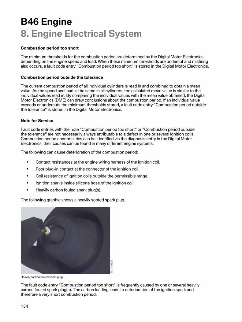
B46�Engine8.�Engine�Electrical�System
134
Combustion�period�too�short
The�minimum�thresholds�for�the�combustion�period�are�determined�by�the�Digital�Motor�Electronicsdepending�on�the�engine�speed�and�load.�When�these�minimum�thresholds�are�undercut�and�misfiringalso�occurs,�a�fault�code�entry�"Combustion�period�too�short"�is�stored�in�the�Digital�Motor�Electronics.
Combustion�period�outside�the�tolerance
The�current�combustion�period�of�all�individual�cylinders�is�read�in�and�combined�to�obtain�a�meanvalue.�As�the�speed�and�load�is�the�same�in�all�cylinders,�the�calculated�mean�value�is�similar�to�theindividual�values�read�in.�By�comparing�the�individual�values�with�the�mean�value�obtained,�the�DigitalMotor�Electronics�(DME)�can�draw�conclusions�about�the�combustion�period.�If�an�individual�valueexceeds�or�undercuts�the�minimum�thresholds�stored,�a�fault�code�entry�"Combustion�period�outsidethe�tolerance"�is�stored�in�the�Digital�Motor�Electronics.
Note�for�Service
Fault�code�entries�with�the�note�"Combustion�period�too�short"�or�"Combustion�period�outsidethe�tolerance"�are�not�necessarily�always�attributable�to�a�defect�in�one�or�several�ignition�coils.Combustion�period�abnormalities�can�be�identified�via�the�diagnosis�entry�in�the�Digital�MotorElectronics,�their�causes�can�be�found�in�many�different�engine�systems.
The�following�can�cause�deterioration�of�the�combustion�period:
• Contact�resistances�at�the�engine�wiring�harness�of�the�ignition�coil.• Poor�plug-in�contact�at�the�connector�of�the�ignition�coil.• Coil�resistance�of�ignition�coils�outside�the�permissible�range.• Ignition�sparks�inside�silicone�hose�of�the�ignition�coil.• Heavily�carbon�fouled�spark�plug(s).
The�following�graphic�shows�a�heavily�sooted�spark�plug.
Heavily�carbon�fouled�spark�plug
The�fault�code�entry�"Combustion�period�too�short"�is�frequently�caused�by�one�or�several�heavilycarbon�fouled�spark�plug(s).�The�carbon�loading�leads�to�deterioration�of�the�ignition�spark�andtherefore�a�very�short�combustion�period.
B46�Engine8.�Engine�Electrical�System
135
Increased�soot�loading�at�the�spark�plugs�accompanied�by�a�reduction�in�the�combustion�period�maybe�caused�by�the�following:
• Fault�in�the�mixture�preparation-�leaks�at�the�air�intake�system-�fault�at�the�injector-�fault�at�the�high�pressure�pump-�deposits�in�the�area�of�the�intake�valves
• Fault�in�the�engine�electrical�system-�fault�in�the�area�of�the�coolant�temperature�sensor-�fault�in�the�area�of�the�oxygen�sensor-�fault�in�the�area�of�the�hot�film�air�mass�meter
• Large�number�of�cold�starts-�frequent�catalytic�converter�heating�phases-�few�self-cleaning�phases�of�the�spark�plugs
With�the�fault�code�entry�"Combustion�period",�a�potential�component�fault�at�the�relevant�coil�can�beconfirmed�or�disproved�by�cross-swapping�the�ignition�coil.
If�misfiring�occurs�following�component�errors,�different�test�modules�in�the�workshop�and�diagnosissystem�ISTA�can�be�processed.�As�the�causes�of�faults�in�the�ignition�system�are�many�and�varied,�thevarious�test�and�diagnosis�instructions�in�the�test�module�must�be�followed.�If�a�faulty�component�isreplaced�without�eliminating�the�actual�cause,�this�will�only�remedy�the�problem�in�the�short�term.
8.3.2.�Ignition�coils
Overview�of�ignition�coils
The�following�graphic�provides�an�overview�of�the�different�ignition�coils�currently�used�with�thevarious�BMW�engines:
B46�Engine8.�Engine�Electrical�System
136
Overview�of�ignition�coils
Index ExplanationA Compact�ignition�coil�(manufacturer:�Eldor)B Rod�ignition�coil�(manufacturer:�Delphi)1 Electrical�plug-in�contact2 Silicone�hose3 Mounting�bolt4 Rear�closure�plate
The�table�below�provides�an�overview�of�the�engines�in�which�the�various�ignition�coils�are�used:
Engine Compact�ignition�coil Rod�ignition�coilB46 XN20 XN55 XN63�TU2 XN74�TU X
B46�Engine8.�Engine�Electrical�System
137
Compact�ignition�coil
Ignition�coil,�Bx8�engine
Index Explanation1 Manufactured�for�BMW2 BMW�part�number3 Supplier4 Supplier�code5 Production�date6 Terminal�157 Terminal�4a8 Silicone�hose9 Serial�number10 Terminal�111 Mounting�bolt
The�primary�and�secondary�coil�required�to�raise�the�ignition�voltage�can�be�found�in�the�area�of�theelectrical�plug-in�contact.�The�transfer�factor�achieved�by�both�coils�is�around�1:80.
B46�Engine8.�Engine�Electrical�System
138
When�servicing�the�ignition�coils,�observe�the�following:
• A�slight�rotational�movement�when�pulling�out�and�inserting�the�ignition�coils�makesdisassembly�and�installation�easier.
• There�must�be�no�sign�of�contamination�by�oil�or�other�fluids�in�the�area�of�theelectrical�plug-in�contact.
• The�pins�of�the�electrical�plug-in�contact�must�not�be�bent.• There�must�be�no�sign�of�cracking�on�the�silicone�hose.• The�spring�which�transmits�the�ignition�spark�must�be�positioned�at�the�center
of�the�silicone�hose.• The�silicone�hose�of�the�ignition�coils�must�not�come�into�contact�with�fuel�or�mineral�oils.• The�specified�torque�of�the�mounting�bolt�must�be�observed.• Prior�to�disassembly�of�the�ignition�coil,�remove�the�plug-in�contact�from�the�engine
wiring�harness,�as�the�ignition�coils�cannot�be�operated�without�spark�plugs.
The�ignition�coils�are�not�fuel-resistant.�All�ignition�coils�should�therefore�be�removed�before�openingthe�fuel�system.�Fuel�residues�must�be�removed�before�inserting�the�ignition�coils�in�the�spark�plugshaft.
8.3.3.�Spark�plugsThe�position�of�the�spark�plug�electrode�in�the�combustion�chamber�is�therefore�particularly�important.To�avoid�coating�the�spark�plug�electrode�with�fuel,�it�is�positioned�geometrically�between�the�fuel-injection�spray�of�the�injector.
A�change�interval�applies�for�spark�plugs�and�they�must�be�renewed�in�accordance�with�themanufacturer's�specifications.�To�avoid�damage�and�ensure�perfect�function�of�the�spark�plugs,the�prescribed�tightening�torques�must�be�observed.
8.4.�System�overview�for�engine�electrical�systemThe�sensors�and�actuators�are�already�known�from�other�engines�and�are�therefore�not�described�indetail�in�this�documentation.�The�following�graphics�provide�an�overview�of�the�different�installationpositions�of�the�sensors.
B46�Engine8.�Engine�Electrical�System
139
8.4.1.�Transmission�side
System�overview�for�electrical�system�in�the�B38�engine,�transmission�side
Index Explanation1 Rail�pressure�sensor2 Ignition�coil3 Quantity�control�valve4 High-pressure�pump5 Actuator�of�electrically�adjustable�wastegate�valve6 Broadband�oxygen�sensor�before�catalytic�converter7 VANOS�exhaust�camshaft8 Voltage�jump,�oxygen�sensor�after�catalytic�converter9 Pinion�starter10 Crankshaft�sensor,�crankshaft
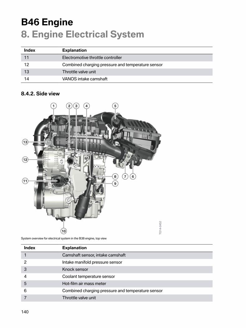
B46�Engine8.�Engine�Electrical�System
140
Index Explanation11 Electromotive�throttle�controller12 Combined�charging�pressure�and�temperature�sensor13 Throttle�valve�unit14 VANOS�intake�camshaft
8.4.2.�Side�view
System�overview�for�electrical�system�in�the�B38�engine,�top�view
Index Explanation1 Camshaft�sensor,�intake�camshaft2 Intake�manifold�pressure�sensor3 Knock�sensor4 Coolant�temperature�sensor5 Hot-film�air�mass�meter6 Combined�charging�pressure�and�temperature�sensor7 Throttle�valve�unit
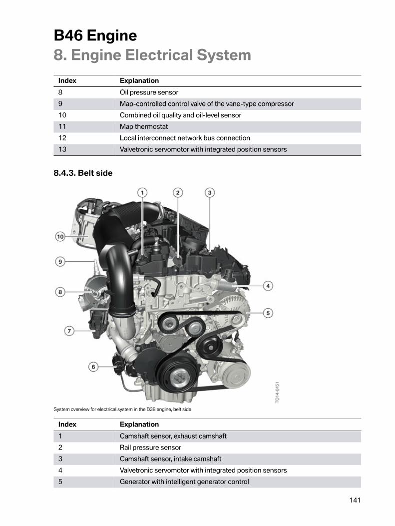
B46�Engine8.�Engine�Electrical�System
141
Index Explanation8 Oil�pressure�sensor9 Map-controlled�control�valve�of�the�vane-type�compressor10 Combined�oil�quality�and�oil-level�sensor11 Map�thermostat12 Local�interconnect�network�bus�connection13 Valvetronic�servomotor�with�integrated�position�sensors
8.4.3.�Belt�side
System�overview�for�electrical�system�in�the�B38�engine,�belt�side
Index Explanation1 Camshaft�sensor,�exhaust�camshaft2 Rail�pressure�sensor3 Camshaft�sensor,�intake�camshaft4 Valvetronic�servomotor�with�integrated�position�sensors5 Generator�with�intelligent�generator�control
B46�Engine8.�Engine�Electrical�System
142
Index Explanation6 Solenoid�switch,�pinion�starter7 Actuator�of�electrically�adjustable�wastegate�valve8 Broadband�oxygen�sensor�before�catalytic�converter9 Voltage�jump,�oxygen�sensor�after�catalytic�converter10 Digital�Motor�Electronics�(DME)


Bayerische�Motorenwerke�AktiengesellschaftQualifizierung�und�TrainingRöntgenstraße�785716�Unterschleißheim,�Germany